Cisco HyperFlex with Red Hat OCP and Kasten by Veeam for Hybrid Cloud
Available Languages
Bias-Free Language
The documentation set for this product strives to use bias-free language. For the purposes of this documentation set, bias-free is defined as language that does not imply discrimination based on age, disability, gender, racial identity, ethnic identity, sexual orientation, socioeconomic status, and intersectionality. Exceptions may be present in the documentation due to language that is hardcoded in the user interfaces of the product software, language used based on RFP documentation, or language that is used by a referenced third-party product. Learn more about how Cisco is using Inclusive Language.
- US/Canada 800-553-2447
- Worldwide Support Phone Numbers
- All Tools
 Feedback
 Feedback
In partnership with:

![]()

About the Cisco Validated Design Program
The Cisco Validated Design (CVD) program consists of systems and solutions designed, tested, and documented to facilitate faster, more reliable, and more predictable customer deployments. For more information, go to: http://www.cisco.com/go/designzone.
Hybrid cloud has become the de facto deployment and operating model in most Enterprises. In a study conducted by 451 Research across 2500 organizations from around the globe, 82% of the IT decision makers responded that they are already using a hybrid cloud model. Cloud computing from hyper-scalers such as Amazon Web Services (AWS), Microsoft Azure and Google Cloud offer limitless scale and flexibility, but it also comes with increasingly high costs, at times higher risk, leaving Enterprises with less control over their business-critical applications and data. As a result, Enterprises are adopting a hybrid cloud strategy that allows them to optimally use both on-prem and public cloud infrastructure to meet their computing needs.
Hybrid cloud model enables Enterprises to:
● Leverage public cloud for specific use cases, for example, to meet short-term spikes in demand or for disaster recovery (DR). Enterprises can reduce their CAPEX by not having to invest in under-utilized on-prem resources by leveraging public cloud resources. However, any DR strategy that requires data movement back to the Enterprise could get very costly as cloud providers charge considerably more for moving the data out of the cloud than for moving data into the cloud.
● Benefit from higher availability inherent in the hybrid cloud model. The Enterprise’s data center is now distributed across different infrastructures in different geographical locations, one managed by the Enterprise and the other by the cloud provider. As such, in most cases and if designed properly, a failure in one location should only impact that location.
● Accelerate innovation through increased agility as Enterprises can quickly spin up environments in the public cloud to start their development efforts and still have the option to deploy the application on-prem for testing or production where it might be easier to integrate into existing tools and processes. It also allows them to retain control of their data.
● Flexibility to select an optimal infrastructure and location that best meets their business needs. Each organization will have unique costs, compliance, security, performance, and other requirements and it helps to have more options.
Some of the common Enterprise use cases for hybrid cloud are:
● Enabling cloud-native environments anywhere, either on-prem or public cloud, with consistent life cycle management across a hybrid infrastructure environment. Enterprises need this to accelerate their application modernization efforts and for developing new applications. In production, the hybrid model enables them to deploy some applications in the cloud while keeping others on-prem, or host applications in both environments for redundancy, load-balancing and so on.
● Development and Test (Dev/Test) where multiple teams in an application’s build/release cycle need multiple infrastructure environments for development, testing, production and so on. For example, organizations may start their initial development in the public cloud where they can quickly spin up an environment, but then will deploy that application into production on-prem where they can easily access backend data, tooling, and other resources.
● Backup and recovery where the application resides either on-prem or distributed across both on-prem and cloud, but the data is backed up in the cloud, with a second backup on-prem. Recovery in this case can be to on-prem and/or cloud depending on the application. This can also be Backup and restore/recovery to the same location as opposed to a different environment from where the original backup was done.
● Cloud bursting or data center extension where an application scales into the cloud to meet peak demands or to enhance the on-prem application using Machine Learning or other data-intensive computations running in the cloud.
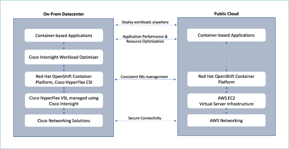
The solution presented in this document will address the first three of these use cases and deliver a foundational cloud-native hybrid-cloud infrastructure with operational simplicity, ease of use, and data management across a hybrid cloud deployment . It will enable developers and operators to quickly deploy cloud-native workloads anywhere with consistent operational experience across on-prem and public cloud environments. The solution is built using Cisco HyperFlex, Cisco Intersight, Amazon Web Services (AWS), and Red Hat OpenShift Container Platform (OCP). The solution also uses VMware vSphere Container Storage Interface (CSI) to dynamically provision persistent storage for stateful Kubernetes (K8S) workloads running on Cisco HyperFlex. Kasten K10 by Veeam is used to protect the application data by providing capabilities for Backup and Restore and Application Mobility from cloud to on-prem and vice-versa. Cisco Intersight Workload Optimizer (IWO) is leveraged to ensure application performance, optimize resource usage, and manage cloud costs in a hybrid cloud deployment. The on-prem infrastructure deployment is automated using Red Hat Ansible to provide Infrastructure as Code (IaC) that can be integrated into existing CI/CD pipelines or other automation to accelerate deployments.
This chapter contains the following:
● Audience
Hybrid architectures are complex and challenging, and ad-hoc deployments that often occur organically in many Enterprises, only add to that challenge, increasing the risk and cost for Enterprises. To address this, Enterprises need a hybrid cloud strategy and architecture that can deliver an agile, responsive infrastructure to its users to power new applications and innovations. The solution presented here can serve as a foundational hybrid-cloud reference architecture for Enterprises, with the simplicity, agility, and operational consistency that IT and Dev-Ops need.
The intended audience for this document includes, but is not limited to, sales engineers, field consultants, professional services, IT teams, partners, and customers who are working on or interested in designing and deploying Cisco’s Hybrid Cloud solutions.
This document is a Cisco Validated Design (CVD) for a Cisco hybrid cloud infrastructure solution for cloud-native workloads. The document provides the end-to-end design with detailed procedures for implementing the solution across a Cisco data center and public cloud. Information about the hardware and software components used to validate the solution in Cisco’s internal labs is also provided.
This is the second hybrid cloud solution from Cisco with Cisco HyperFlex and Red Hat OCP. At a high level, the solution delivers a simple, flexible, and scalable infrastructure for an Enterprise’s cloud-native efforts, enabling workloads to be deployed anywhere from on-prem to a public cloud. The solution supports the following hybrid cloud use cases:
● Enable cloud-native environments anywhere with consistent management
● Development and Test
● Backup and Restore to same location
● Application Mobility between on-prem and public cloud
Other capabilities in this release of the solution are:
● Support for Kasten K10 by Veeam (5.5.4)
● Support for VMware vSphere 2.4.1
● Support for Cisco HyperFlex release 5.0(2a)
● Support for Red Hat OpenShift Container Platform (OCP) 4.10
● Cisco Intersight for consistent, centralized operations across a hybrid environment
● Red Hat Hybrid Cloud Console and OpenShift cluster console for consistent, centralized K8S management across a hybrid environment
● Application performance monitoring with cloud cost management and resource optimization using Cisco Intersight Workload Optimizer (IWO) to ensure the performance of containerized applications in a hybrid deployment.
● IaC using Red Hat Ansible for the automated deployment of on-prem compute, storage, and networking
● Automated Install of Red Hat OCP on HyperFlex Virtual Server Infrastructure (VSI) and on AWS EC2 instances using Installer Provisioned Infrastructure (IPI) method
This solution provides a foundational reference architecture for a hybrid cloud infrastructure solution. The solution enables Enterprises to deploy and develop cloud-native applications anywhere, with consistent management and operational experience for both developers and IT Operations/Dev-Ops teams. The solution also supports two common hybrid cloud use cases, namely Backup and Restore and Dev/Test as outlined earlier.
A hybrid cloud, by definition, is a cloud-computing architecture consisting of at least one on-prem location, a public cloud, and a secure network that interconnects the two locations. This solution delivers a hybrid cloud using a combination of Cisco, Red Hat, and AWS products and technologies as outlined below.
● Cisco HyperFlex standard clusters provide Enterprise-class software-defined compute, storage, and server networking for the on-prem Enterprise data center. Cisco HyperFlex delivers operational simplicity and agility without compromising scale, performance, or flexibility.
● Cisco Intersight provides cloud-based infrastructure management with centralized visibility and operations for all HyperFlex, Cisco UCS, and supported third-party infrastructure that an Enterprise has located anywhere across the globe, from edge locations to Enterprise data centers. Intersight’s SaaS delivery model enables IT teams to benefit from the continuous delivery of innovations and features without having to life cycle manage the management platform. Integration of vCenter, AWS, and OCP nodes in Intersight enables full-stack visibility, monitoring, and resource optimization.
● Cisco Networking using on-prem CSR 1000v and AWS Transit Gateways provides secure hybrid cloud connectivity.
● Red Hat OpenShift Container Platform provides a highly secure, Enterprise-class Kubernetes orchestration platform with development and operational tools that simplify cloud-native efforts. OCP also delivers a consistent operational experience across both on-prem and public cloud.
● Red Hat Hybrid Cloud Console provides cloud-based centralized management of OCP clusters distributed across on-prem and public clouds in a hybrid deployment. The OCP clusters in the solution, hosted on HyperFlex VSI and AWS, are also deployed from the Red Hat Hybrid Cloud Console.
● VMware vSphere CSI enables dynamic provisioning of persistent storage for cloud-native workloads hosted on Cisco HyperFlex VSI and using Cisco HyperFlex as the underlying storage.
● VMware vSphere provides the virtualization on HyperFlex infrastructure. OCP clusters are deployed on VMs on HyperFlex and EC2 instances on AWS.
● Kasten K10 by Veeam is purpose built for Kubernetes and provides cloud-native data management and protection that is easy to use, secure and scalable. It enables critical data protection capabilities in the solution such as application backup/restore, application mobility, and disaster recovery for Kubernetes applications across hybrid cloud deployments.
● Cisco Intersight Workload Optimizer ensures application performance with real-time analytics and automated decision-making that can adapt to changes real-time through actions that move workloads, add compute and memory resources and so on. IWO continuously monitors components and resources to optimize resource usage and manage cloud-costs with full-stack visibility across a hybrid deployment.
● Infrastructure as Code using Red Hat Ansible automates the deployment of on-prem hyperconverged infrastructure, and networking to speed up deployment and for integration into existing Enterprise automation and/or CI/CD pipelines.
The end-to-end solution was validated in Cisco’s internal labs with Cisco and partner recommended best practices in place.
This chapter contains the following:
● Red Hat OpenShift Container Platform (OCP)
● Cisco Intersight Workload Optimizer (IWO)
Cisco HyperFlex is a highly flexible, resilient, and scalable hyper-converged virtual server infrastructure (VSI) platform capable of supporting an organization’s most mission critical and performance-intensive workloads, both traditional and cloud-native. Cisco HyperFlex systems with Intel Xeon Scalable processors are certified as an Intel Select Solution for Hybrid Cloud deployments. Cisco HyperFlex provides software-defined infrastructure with software-defined computing and storage enabled by Cisco Unified Computing System (Cisco UCS) servers and Cisco HyperFlex Data Platform (HXDP) software. HyperFlex systems can be deployed and managed from the cloud using Cisco Intersight to quickly deliver software-defined compute and storage to any location within the Enterprise. Cisco Intersight offers centralized management of all HyperFlex systems (and Cisco UCS) with a comprehensive set of features and capabilities to simplify and ease operations.
Cisco HyperFlex is engineered for data integrity, reliability, and availability to ensure business continuity and data protection. Cisco HyperFlex provides Enterprise-class shared storage with data services such as:
● Replication based on the replication factor configured, stripes and replicates data across nodes in the cluster to protect against single or multi-component failures.
● Native replication replicates data to other clusters for backup or disaster-recovery purposes. Each node participates in the data transfer, minimizing the performance impact.
● Synchronous replication in HyperFlex stretch clusters maintains data in two locations at the same time to enable failover from one location to the other with zero Recovery Point Objective (RPO) and very short Recovery Time Objective (RTO).
● Data deduplication is always on to reduce storage capacity which on virtualized clusters with virtual machines running multiple instances of an operating system, often the same, results in large amounts of replicated data.
● Data compression further reduces storage requirements, lowering costs. HyperFlex uses a log-structured file system that is designed to store variable-sized blocks, reducing internal fragmentation.
● Thin provisioning allows large data volumes to be created without requiring actual storage until it is needed so that storage capacity isn’t being reserved without being used.
● Fast, space-efficient clones rapidly replicate storage volumes so that virtual machines can be replicated simply through metadata operations, with actual data copied only for write operations.
● Data protection API enables enterprise backup tools to access data volumes for consistent per-VM backup operations.
Cisco HyperFlex Data Platform (HXDP)
The foundation for Cisco HyperFlex systems is the Cisco HyperFlex Data Platform software that runs on each node in a Cisco HyperFlex cluster. Cisco HyperFlex Data Platform is a purpose-built, high-performance, log-structured, scale-out file system with enterprise-class storage features. The HXDP software runs on Cisco HyperFlex (HX-series) nodes to create a highly available cluster. Each Cisco HyperFlex server/node includes a Cisco HyperFlex Data Platform controller or Storage Controller Virtual Machine (SCVM) that implements the scale-out and distributed file system using internal flash-based SSDs, NVMe storage, or a combination of NVMe, flash-based SSDs and high-capacity HDDs to store data. The distributed controller design prevents the controller from becoming a bottleneck, unlike many Enterprise storage systems. Each controller assumes direct control of all drives on a node via PCI passthrough and communicates with other controllers over 10 or 40 GbE to aggregate all available capacity across all nodes into a single pool of storage. As nodes are added, the cluster scales linearly to deliver computing, storage capacity, and I/O performance.
Each Cisco HyperFlex node also run IOvisor as a software VIB (SCVM client) inside the hypervisor to enable access to the datastores presented by the HyperFlex storage cluster. HyperFlex provides both high-performance and resiliency as the stored data is distributed across all nodes and all nodes participate in serving I/O.
Cisco HyperFlex provides several hardware configuration options. Enterprises can customize the Cisco HyperFlex server configuration as needed to meet business and workload requirements.
For more details on Cisco HyperFlex Data Platform software architecture and design, see: https://www.cisco.com/c/en/us/products/collateral/hyperconverged-infrastructure/hyperflex-hx-series/white-paper-c11-736814.html
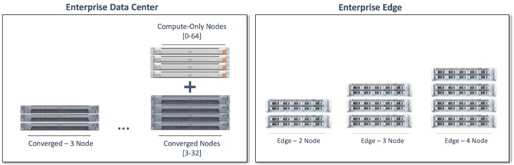
Cisco HyperFlex Design Options
Cisco HyperFlex offers enterprise-class features and performance with distributed, scale-out storage and operational simplicity for an Enterprise’s cloud-native efforts in a hybrid environment. Some additional factors that make HyperFlex particularly well-suited as a hybrid cloud platform are:
● Flexibility
Cisco HyperFlex supports modern and traditional business-critical Enterprise applications with GPU acceleration, flexible choice of processors (Intel, AMD), disk capacity and type, network bandwidth and interface type, form factor, and storage. Virtual Machines and containers running on Cisco HyperFlex can leverage HyperFlex storage using NFS and HX CSI, respectively. Cisco HyperFlex can also provide iSCSI storage to external iSCSI clients such as Windows servers, Linux servers, and so on. Cisco HyperFlex can integrate into existing environments; VMs running on Cisco HyperFlex can mount existing Enterprise storage using NFS, iSCSI, or FC. Cisco HyperFlex systems can also connect to existing Cisco UCS FIs with other Cisco UCS server platforms.
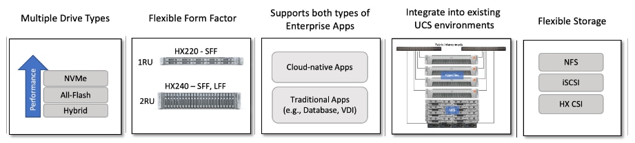
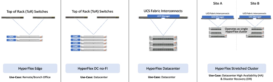
Cisco HyperFlex is also a very flexible, adaptable, and scalable platform that can be deployed anywhere from Enterprise data centers to edge locations with centralized deployment and management from Cisco Intersight. It is available in multiple configuration options such as HX edge and stretched cluster to support different Enterprise use cases.
Cisco HyperFlex with support for multiple drive (Hybrid, All-Flash, NVMe) and node types (HX220, H240) can independently scale compute and storage. The cluster can also be expanded incrementally, one node at a time, with linear performance.
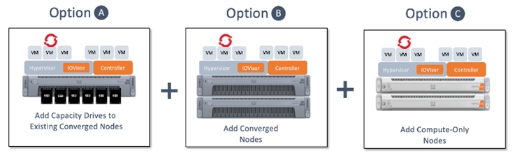
● Scalability
At the time of writing this document, a HyperFlex cluster can start with as few as 2-nodes in a Cisco HyperFlex edge cluster and expand up to 96 nodes in a single cluster using a combination of converged and compute-only nodes. The flexibility to independently scale compute and storage allows Enterprises to tune the cluster performance to meet workload requirements using a combination of CPU, memory, GPU acceleration, and storage. A 4-node, 2RU HyperFlex system with 15TB NVMe drives and 16 x 256GB DIMMs can provide over a petabyte of storage capacity and 4TB of memory, respectively.
The Cisco HyperFlex platforms also offer multiple network interface options with speeds of 1-, 10-, and 25-Gbps on the edge platforms and 10-, 25-, 40-, and 100-Gbps on core data center platforms.
● Security
Security is an integral part of Cisco HyperFlex and has several security features:
◦ Data-at-Rest-Encryption with self-encrypting drives (SED) with Enterprise key management software using local passphrase or remote key management.
◦ Native Software Encryption of filesystem built into Cisco HyperFlex with key management through Cisco Intersight
◦ Security Baseline System Checks is part of HyperFlex Health Check capabilities in Cisco Intersight
◦ Secure CLI/Shell reduces attack surface by limiting commands and access via SSH to ‘admin’ user only.
◦ Secure Boot verifies the trustworthiness of ESXi hypervisor by chaining each stage of boot with a hardware root of trust provided by the Cisco Trust Anchor Module
◦ Security Hardened APIs with support for Secure Technical Implementation Guides (STIGs) for all vSphere components
For more information, see: Cisco HyperFlex - Hyperconverged Infrastructure (HCI) on cisco.com
A standard Cisco HyperFlex cluster requires a minimum of three HX-Series converged nodes with compute and storage. Data is replicated across at least two of these nodes, and a third node is required for continuous operation in the event of a single-node failure. Each node that has disk storage is equipped with at least one high-performance SSD drive for data caching and rapid acknowledgment of write requests. Each node also is equipped with additional disks, up to the platform’s physical limit, for long term storage and capacity.
Cisco HyperFlex servers come in multiple form-factors (1RU, 2RU) with a range of Intel and AMD processor, memory, and drive options. For a complete list of server options and specifications, see: https://www.cisco.com/c/en/us/products/hyperconverged-infrastructure/hyperflex-hx-series/index.html#~models
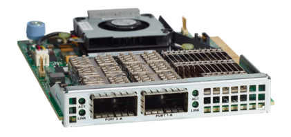
The servers in the solution are equipped with Cisco VIC 1387 mLOM Interface cards.
The mLOM slot is used to install a Cisco VIC without consuming a PCIe slot, which provides greater I/O expandability. It incorporates next-generation converged network adapter (CNA) technology from Cisco, providing investment protection for future feature releases. The card enables a policy-based, stateless, agile server infrastructure that can present up to 256 PCIe standards-compliant interfaces to the host, each dynamically configured as either a network interface card (NICs) or host bus adapter (HBA). The personality of the interfaces is set programmatically using the service profile associated with the server. The number, type (NIC or HBA), identity (MAC address and World Wide Name [WWN]), failover policy, adapter settings, bandwidth, and quality-of-service (QoS) policies of the PCIe interfaces are all specified using the service profile.
The Cisco UCS VIC 1387 Card is a dual-port Enhanced Quad Small Form-Factor Pluggable (QSFP+) 40-Gbps Ethernet, and Fibre Channel over Ethernet (FCoE)-capable PCI Express (PCIe) modular LAN-on-motherboard (mLOM) adapter installed in the Cisco UCS HX-Series Rack Servers. The Cisco UCS VIC 1387 is used in conjunction with the Cisco UCS 6332 or 6332-16UP model Fabric Interconnects.
Cisco UCS Fabric Interconnect
The Cisco UCS Fabric Interconnect (FI) is a core part of the Cisco Unified Computing System, providing both network connectivity and management capabilities for the system. Depending on the model chosen, the Cisco UCS Fabric Interconnect offers line-rate, low-latency, lossless 10 Gigabit, 25 Gigabit, 40 Gigabit, and 100 Gigabit Ethernet connectivity. Cisco UCS Fabric Interconnects provide the management and communication backbone for Cisco UCS and Cisco HyperFlex series Servers. All servers and chassis attached to the Cisco UCS Fabric Interconnects become part of a single, highly available management domain, and provides LAN connectivity to all servers within a Cisco UCS domain. The product family supports Cisco low-latency, lossless Ethernet unified network fabric capabilities, which increase the reliability, efficiency, and scalability of Ethernet networks. The Fabric Interconnect supports multiple traffic classes over the Ethernet fabric from the servers to the uplinks.
There are several models of Cisco UCS Fabric Interconnects. A pair of Cisco UCS 6332 Fabric Interconnects are used in this design.
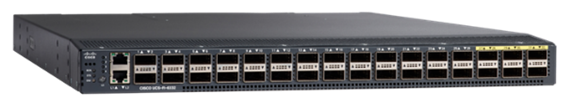
Cisco UCS 6332 Fabric Interconnect
The Cisco UCS 6332 Fabric Interconnect is a one-rack-unit (1RU) 40 Gigabit Ethernet and FCoE switch offering up to 2560 Gbps of throughput. The switch has 32 40-Gbps fixed Ethernet and FCoE ports. Up to 24 of the ports can be reconfigured as 4x10Gbps breakout ports, providing up to 96 10-Gbps ports. Cisco HyperFlex nodes use a 40GbE VIC adapter in order to connect to a Cisco UCS 6300 Series Fabric Interconnect.
Other models of Cisco UCS Fabric Interconnects include the Cisco UCS 6500 and 6400 series in addition to the Cisco UCS 6300 series. Table 1 lists some key differences between these three Cisco UCS FI series.
Table 1. Cisco UCS Fabric Interconnect Models
| Cisco UCS Fabric Interconnects |
UCS 6500 Series |
UCS 6400 Series |
UCS 6300 Series |
| Port Density |
36 |
54 or 108 |
32-40GbE -or- 24 x 40GbE and 16 x 1- and 10GbE |
| Port Speeds |
1/10/25/40/100-Gbps Ethernet or FCoE |
1/10/25/40/100-Gbps Ethernet or FCoE |
1/10/40-Gbps |
| Throughput |
Up to 7.42 Tbps |
- 6454: Up to 3.82 Tbps - 64108: Up to 7.42 Tbps |
Up to 2.56-Tbps |
VMware vSphere Container Storage Interface (CSI)
Container Storage Interface (CSI) framework enables Kubernetes clusters to consume storage from storage back ends that implement the CSI interface for persistent storage. To use CSI-compatible storage back end in OpenShift, Openshift deploys several control plane components in CSI architectural specification and the storage vendors provides the CSI drivers required to interface with the storage back end. A high-level overview of the CSI components running in an OCP cluster is shown in Figure 3.
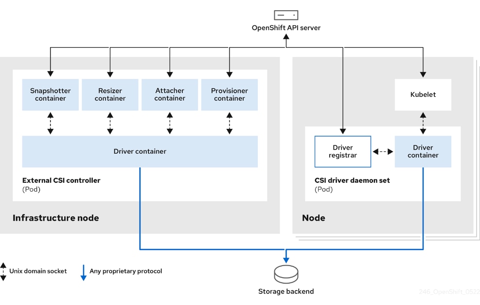
Multiple CSI drivers for different storage back ends can run simultaneously on an OpenShift cluster. However, each driver will need its own external controller, deployment, and daemon set.
Red Hat OCP installs certain CSI drivers by default, one of which is the VMware vSphere CSI used in this solution.
VMware vSphere CSI is an out-of-tree container-based Kubernetes storage plugin that enables stateful container workloads to dynamically request persistent storage through integration with VMware vCenter. vSphere CSI plugin is supported in Red Hat OpenShift as of OCP 4.9 using VM Hardware version 13 or later. The plugin runs in a native Kubernetes cluster deployed in vSphere and can provision persistent volumes using VMware vSphere CSI driver for Virtual Machine Disk (VMDK) volumes.
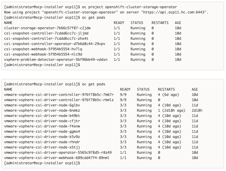
To create CSI-provisioned persistent volumes (PVs) that mount to vSphere storage assets, OpenShift Container Platform, after this feature is enabled, installs the vSphere CSI Driver Operator and the vSphere CSI driver by default in the openshift-cluster-csi-drivers namespace.
● vSphere CSI Driver Operator: After being enabled, the Operator provides a storage class, called thin-csi, that can be used to create persistent volumes claims (PVCs). The vSphere CSI Driver Operator supports dynamic volume provisioning by allowing storage volumes to be created on-demand, eliminating the need for cluster administrators to pre-provision storage.
● vSphere CSI driver: The driver enables you to create and mount vSphere PVs.
VMware vSphere CSI also supports volume snapshots to help protect against data loss on Red Hat OpenShift. Previous non-CSI versions of the vSphere driver did not support volume snapshots. Volume snapshots are also building blocks for enabling application-level storage backup solutions such as Kasten K10 by Veeam used in this solution. Red Hat OCP provides a snapshot controller in the control plane, with VMware providing the CSI snapshot sidecar as a helper container that is installed during the OCP install process. The snapshot controller is deployed by the CSI Snapshot Controller Operator that runs in the openshift-cluster-storage-operator namespace.
Kasten K10 is an enterprise-grade, secure data management platform that Enterprises can deploy to protect their Kubernetes workloads. Kasten K10 can be used for:
● Backup/restore to protect cloud native applications and business critical data.
● Disaster recovery to manage backups replicated off-site to meet business and regulatory requirements.
● Application mobility to move applications between clouds and on-premises for test/dev, load balancing and upgrades.
For cloud-native applications, Kubernetes provides resiliency and scale but protecting the data for stateful workloads (for example, database) requires functionality not available in Kubernetes itself. Cloud-native applications using microservices and containers are also fundamentally different from earlier architectures in that components are frequently added, rescheduled, or removed, resulting in a very dynamic environment and requires a data protection platform that natively understands this architecture to dynamically detect and protect applications and their data.
Kasten K10 is purpose-built for Kubernetes with a deep understanding of cloud-native application design and dependencies, enabling it to effectively co-ordinate backup operations in an application-aware fashion. Kasten K10 protects the complete application stack and provides a solution with unparalleled operational simplicity and ease that makes it easy for both developers and operations teams to deploy and use via a web-based management portal or through Kubernetes-native API/CLI. Kasten K10 also provides comprehensive end-to-end security with encryption and ransomware protection. Kasten K10 data management platform supports both relational and No-SQL databases (for example, Cassandra, MongoDB, Kafka) and seamlessly integrates with various Kubernetes distributions (for example, OpenShift, Rancher), storage vendors (for example, NetApp, Pure Storage), in both on-prem and public cloud (for example, AWS, Google, Azure) and security solutions that further harden the solution and protect the data.
In this CVD solution, Kasten K10 is used to protect the Enterprise applications in a hybrid cloud deployment, running on Red Hat OCP clusters and using Cisco HyperFlex VSI on-prem and AWS in the public cloud as the underlying infrastructure. Kasten K10 is also used in this solution to support application mobility for the Dev/Test use case where an application that is developed and tested in the public cloud is then moved on-prem for staging and production using the on-prem HyperFlex storage. Kasten K10 enables application migration from different public clouds to on-prem infrastructure with ease, simplicity and seamless data conversion between the infrastructure formats while ensuring data security by encrypting the migration data in transit and at rest.
For more information, see: https://www.kasten.io/product/.
As applications and data become more distributed from core data center and edge locations to public clouds, a centralized management platform is essential. IT agility will be a struggle without a consolidated view of the infrastructure resources and centralized operations. Cisco Intersight provides a cloud-hosted, management and analytics platform for all Cisco HyperFlex, Cisco UCS, and other supported third-party infrastructure deployed across the globe. It provides an efficient way of deploying, managing, and upgrading infrastructure in the data center, ROBO, edge, and co-location environments.
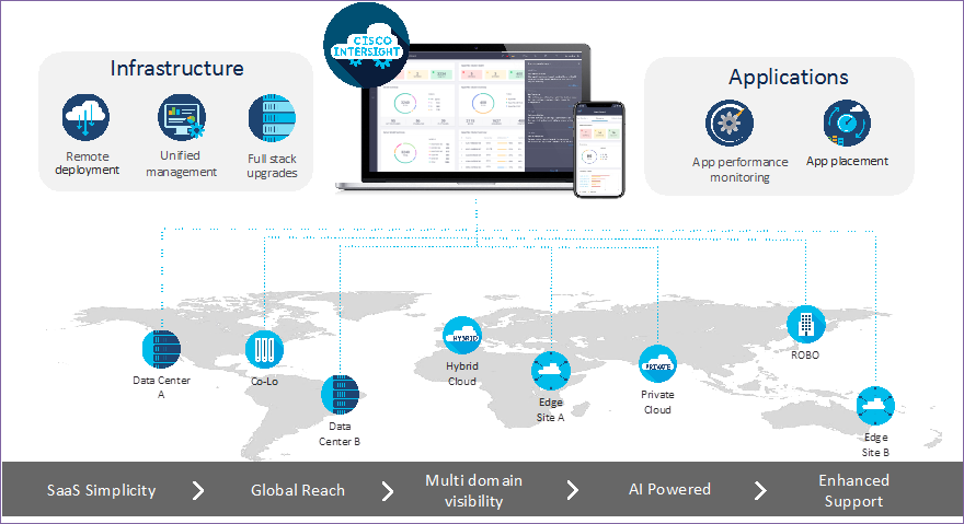
Cisco Intersight provides:
● No Impact Transition: Embedded connector (Cisco HyperFlex, Cisco UCS) will allow customers to start consuming benefits without forklift upgrade
● SaaS/Subscription Model: SaaS model provides for centralized, cloud-scale management and operations across hundreds of sites around the globe without the administrative overhead of managing the platform.
● Enhanced Support Experience: A hosted platform allows Cisco to address issues platform-wide with the experience extending into TAC supported platforms
● Unified Management: Single pane of glass, consistent operations model, and experience for managing all systems and solutions
● Programmability: End to end programmability with native API, SDK’s and popular DevOps toolsets will enable customers to deploy and manage the infrastructure quickly and easily.
● Single point of automation: Automation using Ansible, Terraform and other tools can be done through Intersight for all systems it manages.
● Recommendation Engine: Our approach of visibility, insight and action powered by machine intelligence and analytics provide real-time recommendations with agility and scale. Embedded recommendation platform with insights sourced from across Cisco install base and tailored to each customer
In this solution, Cisco Intersight unifies and simplifies the hybrid cloud operations of Cisco HyperFlex clusters wherever they are deployed. The life cycle management capabilities that Intersight offers specifically for Cisco HyperFlex systems are shown below.
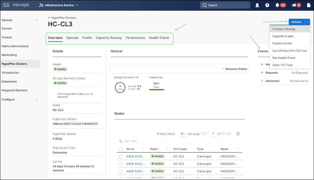
● Deploy Cisco HyperFlex standard/data center cluster including DC-no-FI configurations, and edge clusters.
● Full-stack upgrade of a Cisco HyperFlex cluster from Cisco HyperFlex/Cisco UCS server firmware, HXDP software to VMware vSphere.
● Monitor the status of all actions initiated via Cisco Intersight (for example, HyperFlex install).
● Get security alerts and software advisories with recommendations, alarms, and other notifications.
● Detailed hardware and software component inventory for each system, including hosts, virtual machines, data stores, disks, and encryption key management.
● Storage management through features such as create, delete, mount, and unmount data stores.
● Tools for Hardware Compatibility Checks, capacity planning, monitoring storage performance (IOPs, throughput latency), and health checks.
● Launch vKVM, Cisco UCS Manager, and HyperFlex Connect to access individual cluster management tools.
● Support cases that will be populated with serial numbers of servers in the clusters.
● Customizable dashboard with pre-configured widgets to view the information that is of interest to the administrator.
For more information, go to the Cisco Intersight product page on cisco.com.
Red Hat OpenShift Container Platform (OCP)
Enterprises are modernizing their applications using scalable, cloud-native architectures and technologies such as containers and micro-services that can run anywhere, from private to public to hybrid clouds. Kubernetes (K8s) is an open-source orchestration system that automates the deployment, scaling, and management of containerized applications. Kubernetes is a project within Cloud Native Computing Foundation (CNCF); it is the de facto industry standard for container orchestration. Kubernetes projects have over 3 million contributions from a large open-source community that includes companies such as Red Hat, Cisco and Kasten/Veeam.. Red Hat is also one of the top contributors to the Kubernetes project.
Red Hat OpenShift
Red Hat OpenShift is a commercially packaged product derived from upstream open-source Kubernetes. OpenShift goes beyond standard Kubernetes to provide a to provide a broader cloud-native ecosystem of tools and extensions that make it easier to design, develop, test, and operate a cloud-native environment. OpenShift provides extensions such as built-in security, a user-friendly dashboard, integrated image registries, an embedded operator hub, and integrated CI/CD pipelines. It is a secure Enterprise platform with certified third-party integrations, testing, and support from Red Hat.
Red Hat OpenShift is a suite of three products:
● OpenShift Kubernetes Engine (OKE)
● OpenShift Container Platform (OCP)
● OpenShift Container Platform Plus
Each product includes an Enterprise-class container orchestration system bundled with different value-added components as shown in Figure 4.
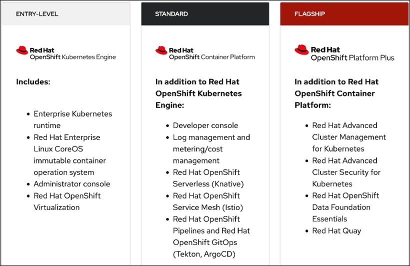
Note: This CVD uses Red Hat OpenShift Container Platform, but Enterprises can also Red Hat OpenShift Container Platform Plus to leverage advanced capabilities.
Red Hat OpenShift Container Platform
Red Hat OCP is a secure, enterprise-class, Kubernetes platform for building, deploying, and managing cloud-native environments and applications across a hybrid cloud. OCP provides enterprise-grade Kubernetes but with developer-focused (for example, a developer console, service mesh) and operational (for example, log and cost management, CI/CD pipelines, GitOps) capabilities and tools to support an Enterprise’s cloud-native efforts. Red Hat OCP uses Red Hat Enterprise Linux CoreOS (RHCOS) as a foundation for running and managing containers using container technologies such as CRI-O and runc. OCP is designed to provide consistent developer and operator experience across a hybrid environment.
Some of the capabilities in Red Hat OCP include:
● Automated deployment of OCP clusters on-prem (bare metal, VMware vSphere, Red Hat OpenStack Platform, Red Hat Virtualization) and in public clouds (Amazon Web Services, Google Cloud Platform, IBM Cloud, Microsoft Azure).
● Automated upgrades of OCP clusters with over-the-air upgrades using web console or OpenShift CLI (oc)
● Add services with push-button ease – Once a cluster is deployed, Red Hat OpenShift uses Kubernetes Operators to deploy additional capabilities and services on the cluster. Red Hat and community supported operators are available in the embedded Operator Hub and can be deployed with the click of a button.
● Multi-cluster management using Red Hat’s cloud-based Hybrid Cloud Console or enterprise-managed Advance Cluster Management (ACM) provides a consolidated view of all clusters, with the ability to easily access and use other K8s technologies and services. OCP clusters can also be individually managed using a web-based cluster console or APIs.
● Persistent storage support – OCP provides support for a broad range of eco-system storage partners including the Cisco HyperFlex storage used in this solution.
● Scalability – OCP can scale to thousands of instances across hundreds of nodes in seconds as needed.
● Automate container and application builds, deployments, scaling, cluster management, and more with ease.
● Self-service provisioning – Developers can quickly and easily create applications on demand with the tools they use most, while operations retain full control over the entire environment.
● Source-to-image deployment – OCP provides a toolkit and workflow for producing ready-to-run images by injecting source code into a container and letting the container prepare that source code for execution.
For more information, see: Red Hat OpenShift Container Platform product page on redhat.com.
Red Hat Hybrid Cloud Console
Red Hat Hybrid Cloud Console is a centralized, SaaS-based management console for managing multiple OCP clusters. It is used in this solution to provide consistent container management across a hybrid environment. The SaaS model enables Enterprises to develop, deploy, and innovate faster across multiple infrastructures and quickly take advantage of new capabilities without the overhead of managing the tool. The console gives Enterprises more control and visibility as environments grow and scale. The Hybrid Cloud Console also provides tools to proactively address issues, open and manage support cases, manage cloud costs, subscriptions, and so on.
For more information, see: Red Hat Hybrid Cloud Console product page on redhat.com
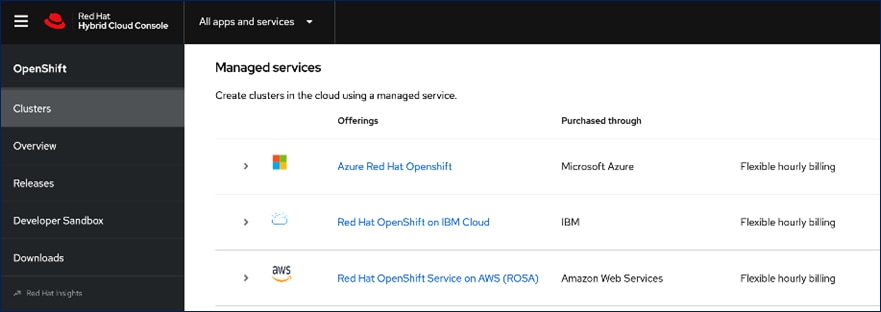
Consumption Models
Red Hat OpenShift is available as a managed service by Red Hat and cloud providers or as self-managed service where the Enterprise manages and maintains the OCP cluster. Unlike other managed Kubernetes services, including ones offered by the public cloud providers, Red Hat OCP managed and hosted on the same public provider environments provides support for the full-stack rather than just Kubernetes, with consistent experience across the hybrid cloud environment. Red Hat OpenShift is a complete, production-ready application platform with additional services such as CI/CD pipelines, monitoring, security, registry, service mesh, and more. included on top of upstream Kubernetes. The managed cloud-hosted services include Red Hat OpenShift Service on AWS, Microsoft Azure Red Hat OpenShift, Red Hat OpenShift Dedicated on Google Cloud or AWS, and Red Hat OpenShift on IBM Cloud.
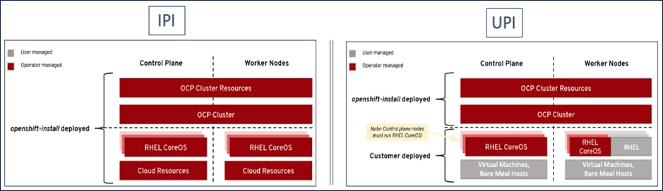
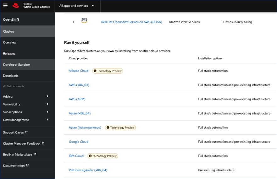
Installation Options
The Red Hat OpenShift Container Platform installer can install and deploy a cluster using either Installer-Provisioned infrastructure (IPI) or the User-Provisioned infrastructure (UPI) methods.
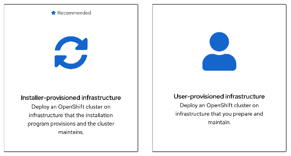
The IPI installation is a prescriptive approach, but it is the quickest way to deploy a cluster. The install implements best practices and is fully automated. The install takes approximately 45minutes and can be deployed with minimal understanding of the underlying infrastructure. In the UPI method, the administrator is responsible for loading the operating system (RHCOS, RHEL) and bringing up the different nodes (for example, bootstrap, master, worker) in an OCP cluster.
In on-prem environments, a third option, Assisted Installer, is also supported where the user provisions and maintains the infrastructure but with step-by-step guidance from the installer.
The installation mechanisms offer either the default install or customizations. For example, IPI Install on AWS can deploy a cluster in a restricted or private network, existing virtual private cloud (VPC), government, or top-secret region, with network customizations or a fully custom install where the installer still provisions the infrastructure.
The Red Hat OCP installer is flexible and provide several options for deploying a cluster in a variety of infrastructure environments. The Hybrid Cloud Console supported environments at the time of writing of this document are:
● On-prem (Bare Metal, Virtual, Private cloud)
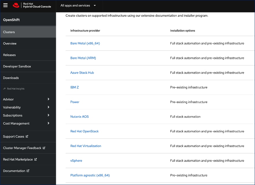
● Public Cloud – Managed service
● Public Cloud – Self-managed
Note: For a complete list of all environments supported using the IPI and UPI installation methods, please refer to the Red Hat OCP documentation for a given release.
Red Hat Enterprise Linux CoreOS (RHCOS)
RHCOS is a lightweight, container-specific operating system, specifically designed for running container workloads. It is based on the secure, enterprise-grade Red Hat Enterprise Linux (RHEL). RHCOS is the default operating system on all Red Hat OCP cluster nodes, and the only operating system supported on control/master nodes. The automated IPI installation method deploys RHCOS on all cluster machines, including compute/worker nodes though RHCOS and RHEL are supported. RHCOS is tightly controlled, allowing only a few system settings to be modified using the Ignition configuration files. RHCOS is designed to deploy an OCP cluster with minimal user configuration and once the cluster is deployed, the cluster will fully manage the RHCOS subsystem.
RHCOS includes:
● Ignition – for initial bootup configuration and disk related tasks on OCP cluster nodes
● CRI-O – Container Engine running on OCP cluster nodes
● Kubelet – Kubernetes service running on OCP cluster nodes
● Set of container tools
Ignition serves as a first boot system configuration utility for initially bringing up and configuring the nodes in the OCP cluster. It also creates and formats disk partitions, writes files, creates file systems and directories, configures users and so on. During a cluster install, the control/master nodes get their configuration file from the temporary bootstrap machine used during install, and the worker nodes get theirs from the control/master nodes. Ignition is designed to initialize systems and all subsequent configuration done using the Machine Config Operator in OCP.
CRI-O is a stable, standards-based, lightweight container engine for Kubernetes that runs and manages the containers. CRI-O implements the Kubernetes Container Runtime Interface (CRI) for running Open Container Initiative (OCI) compliant runtimes. OCP uses the default OCI runtime, runc as the container runtime. CRI-O has a small footprint and a smaller attack surface, making it more secure. OCP uses the default OCI runtime - runc. CRI-O, along with RHCOS provides capabilities such as starting, stopping, and restarting containers. CRI-O is an independent project in Cloud Native Computing Foundation (CNCF) that also supports and maintains Kubernetes.
Kubelet is a Kubernetes service running on every worker node in the cluster. It communicates with the control plane components and processes requests for running, stopping, and managing container workloads.
Container Tools: RHCOS also includes a set of container tools (for example, podman, skopeo, crictl) for managing containers and container images such as start, stop, run list, remove containers and copy, authentication, sign images. RHCOS uses the rpm-ostree system to pull, extract, and write container images to disk for cluster updates.
RHCOS is deployed using configurations in ignition files. The OCP installer creates the Ignition configuration files necessary to deploy the OCP cluster with RHCOS. The configuration is based on the user provided responses to the installer. These files and images are downloaded and installed on the underlying infrastructure by the installer when using the IPI method. However, when using the UPI method, the user must download the RHCOS images, generate the Ignition configuration files and use them to provision the cluster machines.
AWS provides a flexible application computing environment for deploying cloud-native applications. Red Hat OCP cluster on AWS can accelerate application development and delivery by providing a consistent experience for developers and operators across both on-prem and public cloud. AWS is globally available, enabling Enterprises to extend their enterprise deployments to a variety of AWS regions as needed. Red Hat OCP cluster nodes can also be distributed across multiple AWS Availability Zones (AZ) to ensure availability. OCP is also supported on other cloud providers such as Google Cloud Platform, Microsoft Azure, and IBM Cloud. OCP is available as a managed service on AWS, Red Hat OCP Service on AWS (ROSA) and as self-managed. This solution uses the self-managed service and the IPI installation method that was used on-prem. The automated IPI installation method uses several AWS services such as Route 53, DHCP, load balancers, Virtual Private Cloud (VPC) and EC2 instances that are deployed or used as a part of the installation process. Transit Gateways (TGW) attached to the VPC provide connectivity to on-prem resources and services, including K8s clusters and application workloads.
A VPC in AWS provides an isolated virtual networking environment on a shared infrastructure where users can deploy resources to support applications workloads. Enterprises can deploy VPCs in AWS cloud and connect them directly to the on-prem datacenter to enable connectivity between applications, services, and resources in each environment. One mechanism for enabling this connectivity is to use a Site-to-Site VPN to establish an IPsec VPN tunnel between the two locations.
Cisco Intersight Workload Optimizer (IWO)
Cisco IWO provides resource management for cloud-native workloads in a hybrid cloud deployment. It takes a top-down approach to monitoring all resources in a hybrid cloud deployment to ensure that applications are healthy, and the environment is operating in an optimal manner. IWO uses real-time AI-powered analytics to continuously monitor and analyze application workloads and their resource consumption. IWO uses the historical and real-time data to make actionable recommendations (for example, provision additional resources) that can be automatically implemented to ensure application performance before users and services are impacted. IWO provides a cost analysis with each recommendation so that administrators can make better decisions, one that minimizes cloud costs, prevents sprawl, and generally uses resources more efficiently. IWO recommendations can be implemented to consolidate workloads to minimize infrastructure needs. Cisco IWO for planning purposes, to model future workload growth scenarios and to estimate the additional infrastructure that your organization will need and when.
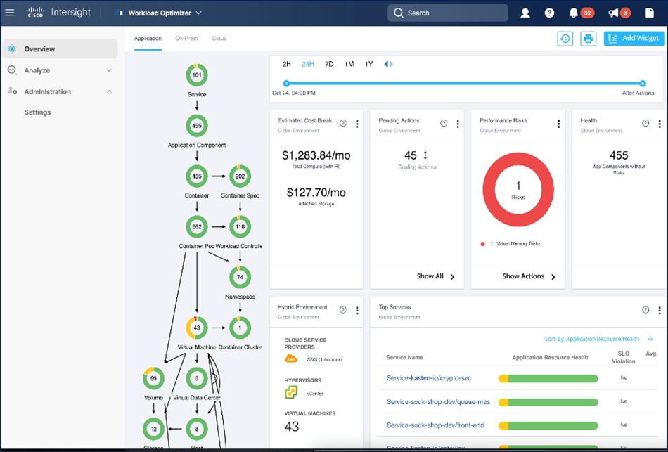
To perform application resource management, Cisco IWO discovers software and hardware components running in your environment and creates an inter-dependency map of all components from an application perspective. It then monitors and analyzes the resources to optimize resource usage while assuring application performance. The inter-dependency map includes all layers of the infrastructure, from the containers and VMs down to the underlying compute, storage, and network infrastructure.
To evaluate and monitor the resource usage of applications, Cisco IWO collects telemetry data from both on-prem and public cloud components. The starting point for this data collection are the targets claimed in Intersight. Intersight supports a broad-range of Cisco and third-party products to provide a holistic top-down view of all infrastructure entities or components for a given application or in each location (on-prem, public). For cloud-native environments, Cisco IWO discovers and monitors the following container specific entities: Service, Application Components, Container, Container Pod, Container Spec, Workload Controller, Container Cluster, Namespace, Virtual Machine, and Volume. Figure 5 shows the inter-dependency map based on the discovered entities from an application perspective, widgets that show the estimated cost breakdown, pending IWO recommendations and actions, performance risks, overall health of the application and the top application services.
You can also use IWO to run simulations for planning purposes and placement recommendations. You can then schedule and implement the changes at your convenience. Intersight Workload Optimizer supports the following action modes:
● Recommend — Recommend the action so a user can execute it from the domain manager rather than from IWO
● Manual — Recommend the action, and provide an option to execute that action through the IWO Web GUI interface
● Automatic — Execute the action automatically without user involvement. IWO waits five minutes between actions.
Action modes specify the degree of automation that should be used for implementing the actions. The action modes in a policy are used to set the business rule. Some of the action types and actions supported by IWO are:
● Types: Placement, Scaling, RI optimization, configuration, start/buy stop, delete
● Actions: Provision, Start, Resize, Buy YRI, reconfigure, move/suspend/delete
IWO also provides several pre-defined plans to analyze and optimize various aspects of the deployment. Some of the plans available are:
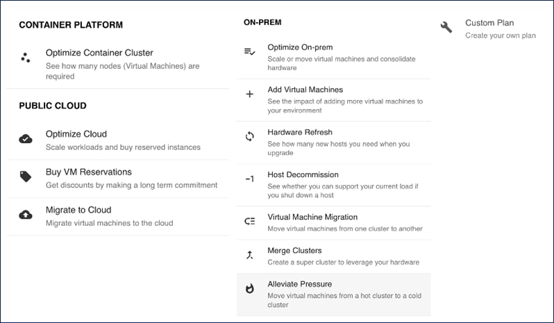
The figure below shows the results of a full container optimization plan that was executed and the actions that IWO recommended as a result.
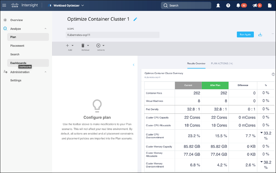
Some of the actions recommended by the execution of this plan are provided below as an example.
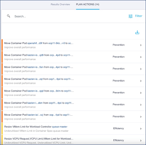
Note: The plan was executed on an under-utilized OCP cluster in Cisco’s internal labs so many of the recommendations are to reduce the vCPU or vMem that the containers can use.
Cisco IWO also provides these recommendations without running plan based on its ongoing monitoring and analysis. These can be viewed selecting and browsing to the entity directly from the inter-dependency map.
For more information, see: Cisco Intersight Workload Optimizer product page on cisco.com
Ansible is an open-source tool for Infrastructure as Code (IaC). Ansible is also used for configuration management and application software deployment. Ansible is designed to be agentless, secure, and simple. Ansible available in Red Hat’s Ansible Automation Platform is part of a suite of tools supported by Red Hat. Ansible manages endpoints and infrastructure components in an inventory file, formatted in YAML or INI. The inventory file can be a static file populated by an administrator or dynamically updated. Passwords and other sensitive data can be encrypted using Ansible Vault. Ansible uses playbooks to orchestrate the provisioning. Playbooks are written in human readable YAML format that is easy to understand. Ansible playbooks are executed against a subset of components in the inventory file. From a control machine, Ansible uses SSH or Windows Remote Management to remotely configure and provision target devices in the inventory based on the playbook tasks.
Ansible is used to provision Cisco HyperFlex VSI and Cisco ACI fabric infrastructure in the solution. Ansible also provides a robust container and Kubernetes management, including Red Hat OpenShift Container Platform that Enterprises can leverage for their automation efforts.
This chapter contains the following:
● Overview
At a high level, the hybrid cloud infrastructure design in this solution consists of an on-prem datacenter, public cloud infrastructure, and a secure network interconnecting the two environments, as shown below:
Virtual Server Infrastructure (VSI)
The on-prem Virtual Server Infrastructure in the solution consists of:
● Four (4) node HyperFlex standard (or Cisco HyperFlex Datacenter) cluster as an application cluster for running cloud-native workloads on a Red Hat OCP cluster. The cluster is deployed and managed from the cloud using Cisco Intersight.
● Four (4) node Cisco HyperFlex standard cluster as a management cluster for hosting services and management components to support the application cluster. The cluster is deployed and managed from the cloud using Cisco Intersight. The services deployed include VMware vCenter managing the application cluster, DNS, DHCP and OCP Installer workstation. The management cluster can also host a management OCP cluster to run services and other components. For example, Red Hat’s Advanced Cluster Manager requires a seed OCP cluster to run on before it can be used for multi-cluster management (see Red Hat OCP in Technology Review section)
The public Virtual Server Infrastructure in the solution consists of:
● Amazon Elastic Compute Cloud (Amazon EC2) instances in the Amazon Web Services (AWS) Cloud provide the virtual server infrastructure in the public cloud. Red Hat OCP clusters are deployed on EC2 instances in a Virtual Private Cloud (VPC). The OCP cluster in the VPC are distributed across 3 x Availability Zones (AZ) in the region for resiliency.
Network Connectivity
● Two redundant IPsec VPN connections provide secure connectivity between the cloud-native environments. The VPN connections are between 2 x CSR1000v routers on-prem and transit gateway routers in the public cloud.
Kubernetes Infrastructure
● Red Hat OCP cluster(s) provide a Kubernetes environment for cloud-native applications and use cases. The clusters are deployed from the cloud on Cisco HyperFlex VSI and on AWS EC2 instances using Red Hat Hybrid Cloud.
● VMware vSphere CSI provides persistent storage for stateful workloads hosted on Cisco HyperFlex VSI.
Application Performance
● Cisco Intersight Workload Optimizer ensure application performance. IWO also provides resource monitoring, optimization, and cost management across this environment.
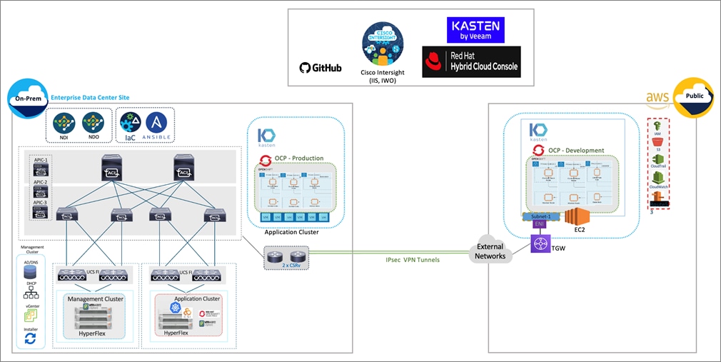
Figure 6 illustrates the end-to-end solution that was designed, built, and validated in Cisco internal labs.
Hybrid Cloud deployments give Enterprises complete flexibility in selecting an optimal location for their workloads based on performance, cost, compliance, and other factors. Some of the design requirements that this hybrid cloud solution addresses are as follows:
● Operational simplicity and agility with the flexibility to deploy and manage workloads anywhere. The on-prem infrastructure that the Enterprise manages, must be easy to deploy and manage without compromising functionality, scale, or performance.
● The infrastructure must also be available as code for integration into existing Enterprise automation or CI/CD pipelines.
● The solution must continuously monitor and optimize the hybrid environment to ensure application performance and manage cloud costs.
The overall solution also addresses the following high-level design goals:
● Resilient design across all layers of the infrastructure with no single point of failure.
● Scalable design with the ability to independently scale compute, storage, and networking as needed.
● Modular design with the ability to upgrade or replace components and sub-systems as needed.
● Flexible design across all layers of the solution that includes sub-system design, individual components used, and storage configuration and connectivity options.
● Operational agility and simplicity through best-of-breed products, SaaS operations, automation, and orchestration tools.
● Incorporates technology and product best practices for the different components in the solution.
The design also addresses two commonly seen use cases in hybrid cloud use deployments:
● Enable cloud-native deployments anywhere, from on-prem to public cloud, while maintaining a consistent management experience.
● Dev/Test for cloud-native workloads where organizations have multiple teams in a CI/CD pipeline that need separate environments, both on-prem and in the public cloud. Development teams may start the work in the cloud, but the application is staged and deployed into production on-prem.
The Cisco Validated Design (CVD) in this document provides a foundational infrastructure architecture for a secure, scalable, enterprise-class hybrid cloud solution to run cloud-native workloads. The main aspects of the design are:
● On-prem infrastructure (compute, storage, virtualization, and network) design
● Infrastructure as Code (IaC)
● Operational ease and consistency as the hybrid model expand to other Enterprise locations
● Secure hybrid cloud connectivity
● Cloud-native Infrastructure design (on-prem, public cloud)
● Persistent Storage for stateful, cloud-native workloads
● Operational ease with consistent cloud-native development and operational experience regardless of the environment
● Application resource monitoring, visibility, and cost management across on-prem and public cloud
● Ensuring application performance in any environment
Infrastructure Design
For cloud-native efforts, Enterprise IT teams need the ability to quickly deploy and manage the infrastructure in the Enterprise data center. The infra in the on-prem location, unlike the public cloud, is typically deployed and managed by the Enterprise. Because of this, IT and DevOps teams need infrastructure that is simple and easy to deploy and operate without compromising performance, scale, or functionality. The data center infrastructure design outlined in this section offers just that.
Figure 7 shows the on-prem infrastructure design in this solution.
Cisco HyperFlex
Cisco HyperFlex provides the on-prem virtual server infrastructure in the solution. Cisco HyperFlex delivers software-define compute, storage, and virtualization as a fully-integrated product, enabling IT teams to spend less time on infrastructure management and more time on other business initiatives. The design uses Cisco HyperFlex clusters, an application cluster for running application workloads, and a management cluster for hosting infrastructure management and other services. The management Cisco HyperFlex cluster is optional in the design as the services running on the management cluster can also be deployed on an Enterprise's existing infrastructure. Both are Cisco HyperFlex standard (data center) cluster with 4 nodes in each cluster.
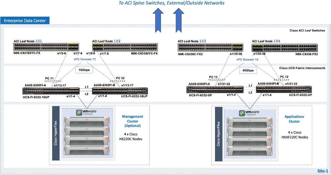
The nodes in the cluster connect to a Cisco UCS domain consisting of a pair of Cisco UCS 6300 Series Fabric Interconnects. The management and application clusters attach to different Cisco UCS domains in this solution, but they could also connect to the same UCS domain if needed. A single UCS domain consisting of a pair of Fabric Interconnects can support multiple Cisco HyperFlex clusters (and Cisco UCS systems). The exact number depends on the number of servers in a given cluster and the port density of the Fabric Interconnect model chosen.
The data center fabric in the solution is a Cisco ACI fabric. The Cisco HyperFlex clusters connect to the ACI fabric through the Cisco UCS 6300 Fabric Interconnects in their UCS domain. Some Cisco HyperFlex systems (for example, DC-no-FI, Edge) can also connect directly to the leaf switches in the ACI fabric. However, connecting to Cisco UCS Fabric Interconnects provides some benefits. It serves as an aggregation point for a group of servers with unified management. The two Cisco UCS Fabric Interconnects in a UCS domain form a highly available, unified, low-latency switching fabric capable of handling I/O traffic from hundreds of servers. It provides connectivity between the servers and systems that connect to it and connectivity to the upstream data center fabric to connect to other UCS domains and networks. Cisco UCS Manager (UCSM) provides unified management for all Cisco HyperFlex and Cisco UCS systems in that Cisco UCS domain. It runs as embedded software on the Fabric Interconnects. The design can use centralized (via Intersight) and local management (using Cisco UCSM), which can be helpful in troubleshooting situations. The unified fabric can also provide Quality-of-Service (QoS) for the different types of traffic traversing the fabric, including Cisco HyperFlex infrastructure (management, storage data, vMotion, replication) and application traffic.
The Cisco HyperFlex UCS domains connect to Nexus 9000 series leaf switches in the ACI fabric for northbound connectivity to other networks within and outside the Enterprise and intra-cluster connectivity when traffic needs to go from one Fabric Interconnect (FI-A) to the other (FI-B) within the same domain. In a Cisco HyperFlex cluster, this typically happens in failure situations. Each Fabric Interconnect connects to a pair of leaf switches for redundancy. For the application cluster, the uplink connections from the Cisco UCS 6300 Fabric Interconnects are:
● 2 x 40GbE links from FI-A, one to each switch in the leaf switch pair
● 2 x 40GbE links from FI-B, one to each switch in the leaf switch pair
The multiple uplinks provide higher bandwidth and resiliency. Cisco UCS FI and Nexus switches support 802.3ad standards for aggregating links into a port channel (PC) using Link Aggregation Protocol (LACP). The 40Gbps links on the FI side are bundled using a port channel, while the links on the Nexus 9000 leaf switch pair are bundled using a virtual port channel (vPC). The Fabric Interconnects use two port channels to connect to the ACI leaf switch pair - one from each FI. The 2 x 40GbE links on each FI connect to different Nexus switches in the leaf switch pair. In the reverse direction, the ACI leaf switches pair uses two vPCs to connect to the Fabric Interconnects - one to each FI. vPC enables links from two switches to be bundled such that it appears as a “single logical" port channel to a third device (in this case, FI). The vPC design provides higher aggregate bandwidth with both link and node-level redundancy. In this design, the total uplink bandwidth for the application UCS domain, is 160Gbps (40Gbps per link x 2 uplinks per FI x 2FI). You can also add more links to the PC/vPC bundle to increase the uplink bandwidth. The Fabric Interconnects can also use higher speed links to connect to the upstream Nexus switches. The Cisco UCS 6300 series Fabric Interconnects used in this solution support 10G and 40G, but other hardware models are available that support 25G and 100G connectivity. The Cisco HyperFlex management cluster is also connected similarly, using a PC/vPC design but uses 4 x 10GbE links for uplink connectivity. The FI uplinks to the ACI fabric operate as trunks, carrying traffic from multiple 802.1Q VLAN IDs to the ACI fabric. The uplinks trunk VLAN traffic for Cisco HyperFlex infrastructure (in-band management, vMotion, storage data) and application networks. The VLANs are also configured on the individual virtual NIC (vNIC) templates going to each server in the HX cluster.
The Cisco HyperFlex nodes in a cluster are dual-homed to the Fabric Interconnects in the UCS domain for high availability. Each server in the application cluster uses a VIC 1387 adapter with two 40Gbps uplink ports to connect to each FI, resulting in two redundant paths, one through each fabric (FI-A, FI-B). The two uplinks provide each server with 2x40Gbps of uplink bandwidth and redundancy in the event of a failure.
Cisco HyperFlex uses an automated installation process to deliver a production-ready Cisco HyperFlex VSI cluster in less than an hour. Either an Installer VM (OVF) or Cisco Intersight can be used to initiate the deployment. Intersight provides a simple workflow/wizard to gather input from the user, validate and begin the installation process. Cisco HyperFlex systems use a best-practice configuration combined with user-provided inputs to generate a cluster profile. The installer uses this profile to deploy and configure the cluster. The profile can also be cloned and re-used (with minimal changes) to deploy additional clusters as needed. Cisco HyperFlex systems typically undergo a factory install process that pre-installs some of the firmware and software required (for example, server firmware, VMware ESXi software), which makes the customer site installation and setup much quicker and easier.
The Cisco UCS Fabric Interconnects (when used) must be claimed as a target for Intersight to discover the servers in the cluster. Intersight and other components will also require connectivity to multiple networks to deploy the cluster. The Cisco ACI fabric provides this connectivity – see the Data Center Fabric – Cisco ACI section for additional details.
The two Cisco HyperFlex clusters in the solution are deployed and managed using Cisco Intersight. The installation results in a complete virtual server infrastructure that is ready for deploying a Red Hat OCP cluster and cloud-native workloads. The virtual server infrastructure is managed using VMware vCenter running on the management Cisco HyperFlex cluster.
Virtual Networking Design
The automated Cisco HyperFlex installation process deploys a VMware vSphere cluster with a pre-defined virtual networking design. The design is identical on all ESXi hosts in the cluster. The design uses four VMware virtual switches (vSwitch) for different types of traffic. The virtual switches deployed by the automated installation process are:
● vswitch-hx-inband-mgmt: This is the default ESXi vSwitch0 that is renamed by the ESXi kickstart file as part of the automated installation process. The switch has two uplinks, active on fabric A and standby on fabric B – by default, jumbo frames are not enabled on these uplinks. The installer deploys multiple port groups on this vSwitch for ESXi management, storage controller VM management and replication (if enabled). The management interfaces include ESXi management interface, SCVM management and replication interface, and a roaming management cluster IP (one per cluster).
● vswitch-hx-storage-data: This vSwitch has two uplinks, active on fabric B and standby on fabric A – by default, jumbo frames are enabled on these uplinks. The installer deploys multiple port groups on this vSwitch for ESXi and storage controller VM storage-data networks. The storage-data interfaces include ESXi host, SCVM storage interface, and a roaming storage cluster IP (one per cluster).
● vswitch-hx-vm-network: This vSwitch has two uplinks, active on both fabrics A and B – by default, jumbo frames are not enabled on these uplinks. However, in this design, it has been reconfigured for jumbo frames through Cisco UCS Manager. The VLANs associated with the above port-groups are all tagged VLANs (not native VLANs) in Cisco UCS vNIC templates. Therefore, these VLANs are also explicitly configured in ESXi/vSphere.
● vmotion: This vSwitch has two uplinks, active on fabric A and standby on fabric B – by default, jumbo frames are enabled on these uplinks. The IP addresses of the VMkernel ports (vmk2) are configured using a post-install script. The VLANs associated with the above port-groups are all tagged VLANs (not native VLANs) in Cisco UCS vNIC templates. Therefore, these VLANs are also explicitly configured in ESXi/vSphere.
Enterprises can migrate the VM network virtual switch to a VMware distributed virtual switch (vDS), but the management and storage-data should stay on the installer-deployed VMware vSwitches. The VMware vDS can be optionally deployed and managed by Cisco ACI using the Virtual Machine Manager (VMM) integration feature. With VMM integration, ACI can dynamically provision port-groups on the vDS when corresponding endpoint groups (or VLANs) are provisioned in the fabric.
The installer deploys four virtual switches on each ESXi host in the cluster, with two uplinks or VMware virtual NICs (vmnics) per vSwitch. The vmnics at the hypervisor level map to virtual NICs (vNICs) on the Cisco UCS VIC adapter deployed in each server. The Cisco HyperFlex installation process configures the service-profiles in Cisco UCS Manager to create the different vNICs and vmnics that are used by the virtual switches running on the ESXi hosts in the Cisco HyperFlex VSI cluster.
Figure 8 shows the default virtual networking deployed on the ESXi hosts in a cluster.
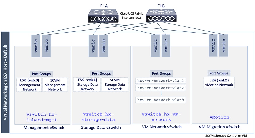
The port groups on each vSwitch correspond to tagged VLANs in the server’s vNIC template. The automated installation provisions the vNIC templates and VLANs on the server side and maps them to port groups on the VMware vSwitch. The vMotion vSwitch port groups and VLAN configuration is done post-deployment using a post-install script.
The virtual machine port groups and VLANs can be provisioned during the initial install or post-deployment using the post-install script. You can also ACI VMM integration to dynamically provision the ESXI networking as needed to roll out new applications and services. However, the ACI VMM integration will not provision the VLANs in the Cisco UCS Fabric Interconnect so this will have to be provisioned separately.
The Red Hat OCP clusters deployed in this solution uses the default VMware vSwitch for VM networks, on a VM network VLAN deployed by the installer.
Data Center Fabric – Cisco ACI
The data center fabric in the solution is a Cisco ACI fabric. ACI provides connectivity to the different components in the solution (Cisco HyperFlex server, Cisco UCS Fabric Interconnects, VMware vCenter, DNS, DHCP, NTP) and other networks, including external connectivity to Cisco Intersight and Red Hat Hybrid Cloud Console. The design separates all infrastructure connectivity necessary for deploying and maintaining the Cisco HyperFlex VSI cluster to a separate ACI tenant (HXV-Foundation). This tenant is responsible for providing the following Cisco HyperFlex infrastructure connectivity:
● Management: A Cisco HyperFlex cluster requires in-band management connectivity to ESXi hosts and storage controller virtual machines (SCVM) in the cluster. The roaming management cluster IP and other endpoints must be accessible to administrators, tools, and other entities outside the fabric. VMware vCenter managing the VSI cluster also needs access to the ESXi management interfaces.
● Storage-data: A Cisco HyperFlex cluster requires storage-data connectivity to ESXi hosts and storage controller virtual machines in the cluster. The roaming storage-data cluster IP and other endpoints must be accessible from the data center fabric.
● VMware vMotion: To enable vMotion of guest VMs running on the application Cisco HyperFlex cluster, the vMotion network must be reachable from VMware vCenter running on the management cluster.
Multiple Cisco HyperFlex clusters connected to the same ACI fabric can use the same management and vMotion infrastructure networks, but the storage-data traffic should be on a dedicated network, one for each cluster. The ACI fabric also provides the following infrastructure connectivity:
● Internet Access for reachability to Cisco Intersight. The UCS domain must be claimed as a target in Intersight before it can be used to deploy the Cisco HyperFlex VSI cluster.
● Reachability to networks and services within the Enterprise, both within and outside the ACI fabric.
For the on-prem Red Hat OCP cluster and application workloads running on the Cisco HyperFlex VSI, the design uses a dedicated Application Tenant (for example, HC-Tenant1) to provide connectivity for the following Cisco HyperFlex network:
● VM network(s): Applications networks deployed on the Cisco HyperFlex application cluster will need connectivity to various networks and services depending on the application requirements. In this solution, the Red Hat OCP is deployed on Guest VM networks and will require reachability to various internal and external entities required to install and operate the OCP cluster.
The ACI tenancy design will separate the infrastructure and application traffic. Multiple application tenants can be deployed as needed. For Red Hat OCP clusters and cloud native workloads, the ACI fabric also provides the following connectivity:
● Internet Access for deploying the Red Hat OCP cluster on Cisco HyperFlex VSI. Cloud-native applications running on the cluster will most likely need Internet access as well.
● Reachability to internal Enterprise networks and services, both within and outside the ACI fabric.
In the ACI architecture, ACI constructs (Tenants, Application profiles, Bridge domains, EPGs, and so on) define and enable the connectivity through the fabric. To meet the infrastructure connectivity requirements outlined above, EPGs and other ACI constructs are defined in the HXV-Foundation tenant to enable this connectivity. The infrastructure VLAN networks provisioned by the Cisco HyperFlex installer are then mapped to end-point groups in ACI to enable forwarding between endpoints in the same network and to other networks. The same is done for application connectivity, but within the application tenant (HC-Tenant1). The ACI constructs to enable this forwarding are provided in the Solution Deployment section (Table 5).
To enable connectivity through the fabric, the ACI fabric must also provide access layer connectivity to the UCS domains and Cisco HyperFlex servers. The access layer connectivity includes:
● Physical connectivity to the UCS domains that Cisco HyperFlex clusters connect to. The PC/vPC design and connectivity are described in the Detailed Design - Cisco HyperFlex section.
● Access Layer configuration to enable connectivity to/from the Fabric Interconnects and Cisco HyperFlex servers in the UCS domain. In ACI, fabric access policies represent the configuration for connecting to access layer devices. To enable this connectivity, policies are first created and then applied to the leaf switch interfaces that connect to the access layer devices.
The specific policies and configuration used to enable the access layer connectivity to the Cisco UCS Fabric Interconnects and Cisco HyperFlex servers for the application cluster in this solution are provided in the Solution Deployment section (Table 4). The policies and profiles will create virtual port channels on the ACI leaf switch pair and enable access layer connectivity to the Cisco UCS Fabric Interconnects in the UCS domain.
The Cisco ACI fabric, together with Cisco UCS FIs provide the connectivity necessary to bring a Cisco HyperFlex cluster online and maintain the cluster post-deployment for hosting application workloads. The on-prem virtual server infrastructure is now ready for deploying a cloud-native environment on-prem using Red Hat OpenShift Container platform.
Hybrid Cloud Connectivity
Cisco offers multiple options for hybrid cloud connectivity between an on-prem location and public cloud. Options include Cisco ACI or VXLAN EVPN fabrics with Nexus Dashboard Orchestrator and Cloud Controller to orchestrate and extend the on-prem networking into the public cloud, SD-WAN, IPsec VPN, and dedicated connections. The hybrid cloud connectivity in this solution is established over the Internet using IPsec VPN tunnels. The IPsec VPN tunnel enables applications, services, and other components to securely access networks and entities in the other location. IPsec VPN tunnels are also referred to as Site-to-Site VPNs. IPsec VPN establishes encrypted tunnels across the Internet to provide secure connectivity for Enterprise traffic in a hybrid deployment. The IPsec VPN tunnels are established between Transit Gateways (TGW) in AWS and a pair of Cisco Cloud Services 1000 series router (CSR1kv). TGWs in AWS serve as transit hubs that can be used to consolidate the hybrid cloud connectivity from multiple VPCs by adding an attachment in each. Alternatively, you can also Virtual Private Gateways (VGW) from each VPC to establish IPsec VPN tunnels to the Enterprise data center, but you can only attach one VPC to this connection. When interconnecting locations in this manner, there should not be any overlapping addressing otherwise you could have routing issues. Figure 9 shows the hybrid cloud connectivity used in this solution. The AWS transit gateway establishes two tunnels to each customer/enterprise gateway (CSR1kv) for redundancy. The design uses two CSRs for higher availability to provide a total for 4 IPsec VPN tunnels between locations. The 4 tunnels will require 4 public IPs to establish the tunnels across the Internet. Enterprise firewalls must be provisioned to allow IPsec protocols and traffic from the AWS side tunnel addresses. By default, AWS expect the enterprise gateway to initiate the Internet Key Exchange (IKE) negotiation process to bring up the tunnel by the by generating traffic. It is recommended that AWS is configured to initiate the IKE negotiation to prevent the tunnel from going down when there is a lull in the traffic flow.
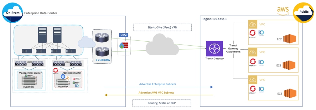
When using Transit Gateways, there are some service limits in terms of MTU, routes, routing protocols, bandwidth, and so on, that you should be aware of. Please review the AWS documentation for details on the VPN limits: https://docs.aws.amazon.com/vpn/latest/s2svpn/vpn-limits.html.
Kubernetes Infrastructure Design
Red Hat OCP provides secure, enterprise-class Kubernetes environment for developing, deploying, and managing cloud-native applications. The Red Hat Hybrid Cloud Console provides centralized, SaaS-based management of OCP clusters deployed anywhere, from on-prem to public cloud. Hybrid Cloud Console provides access to the latest installer package and other tools necessary for securely accessing and managing the cluster for each environment (for example, bare metal, VMware vSphere, AWS, Azure, GCP) and consumption (managed, unmanaged) model that OCP supports. In this solution, Hybrid Cloud Console is used to deploy OCP clusters in both on-prem and public using the Red Hat’s automated Installer Provisioned Installation (IPI) method. This method deploys the full infrastructure using an opinionated, prescriptive approach with best-practices implemented. This is the fastest way to deploy an OCP cluster and OCP continues to manage the infrastructure components post-deployment. The automated OCP installer for each infrastructure environment collects minimal information from the user (for example, on-prem datastore). It does offer some customizations (for example, on AWS - deploy in an existing VPC on AWS) but for more extensive infrastructure customizations, the User Provisioned Installation (UPI) method is available. However, UPI does increase the operational burden on the IT/DevOps teams unlike IPI where OCP manages the infrastructure components.
On-Prem – Red Hat OCP on Cisco HyperFlex VSI
The Red Hat OCP cluster in the solution is deployed on Cisco HyperFlex VSI in the Enterprise data center as shown in Figure 10.
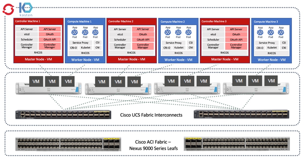
The nodes in the K8s cluster are VMs running on the Application HyperFlex VSI cluster, managed by VMware vCenter running on the management Cisco HyperFlex VSI cluster. The default IPI install deploys 3 x control/master and 3 x compute/worker nodes (VMs) – additional worker nodes can be added as needed. To isolate applications from infrastructure and management, OCP cluster and Cisco HyperFlex VSI are deployed on separate tenants in the Cisco ACI fabric. The same tenant can be used for additional OCP clusters or on new tenants can be added as needed. The OCP cluster is deployed on a VMware vSwitch VM network that was provisioned as a part of the Cisco HyperFlex VSI install. Post-install, the control/master and compute/worker nodes in the cluster are distributed across the ESXi hosts in the Cisco HyperFlex VSI cluster using VMware VM affinity rules. Each controller node runs on a separate physical ESXi host in the 4-node Cisco HyperFlex VSI cluster. Red Hat recommends three control nodes in all production deployments and therefore, a minimum of 3-node, but ideally a 4-node Cisco HyperFlex VSI cluster should be used for OCP deployments. VM affinity rules are also used to distribute the compute/worker nodes across the available ESXi hosts.
Public Cloud – Red Hat OCP on AWS
The Red Hat OCP cluster in AWS is deployed in us-east-1 region. The AWS OCP cluster is Enterprise-managed and deployed from the Hybrid Cloud Console using the same IPI method as on-prem. The deployment is automated by the OCP installer. The cluster design, deployed in us-east-1 region, is shown in Figure 11.
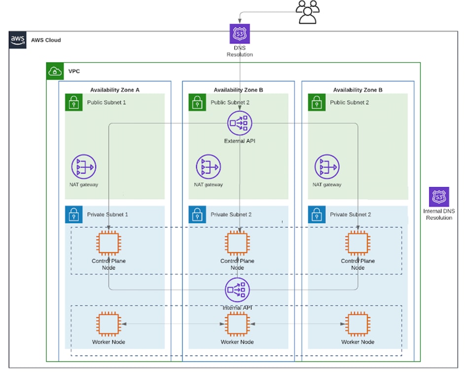
When using the default installation, the installer deploys the cluster in a new dedicated Virtual Private Cloud (VPC) with 6 EC2 instances - 3 x control/master and 3 x compute/worker nodes running on Elastic Block Store (EBS) volumes. The default configuration of the EC2 instances is provided in Table 2.
Table 2. Default Configuration – EC2 Instances
| Component |
EC2 Instance Type |
EBS Volume |
Snapshots |
Availability Zones |
| Master/Control Node-1 |
m6i.xlarge |
Type: gp3, Size: 120GiB, IOPS:3000, Throughout:125 |
Enabled |
us-east-1a |
| Master/Control Node-2 |
m6i.xlarge |
Type: gp3, Size: 120GiB, IOPS:3000, Throughout:125 |
Enabled |
us-east-1b |
| Master/Control Node-3 |
m6i.xlarge |
Type: gp3, Size: 120GiB, IOPS:3000, Throughout:125 |
Enabled |
us-east-1c |
| Worker/Compute Node-1 |
m6i.large |
Type: gp3, Size: 120GiB, IOPS:3000, Throughout:125 |
Enabled |
us-east-1a |
| Worker/Compute Node-2 |
m6i.large |
Type: gp3, Size: 120GiB, IOPS:3000, Throughout:125 |
Enabled |
us-east-1b |
| Worker/Compute Node-3 |
m6i.large |
Type: gp3, Size: 120GiB, IOPS:3000, Throughout:125 |
Enabled |
us-east-1c |
The cluster nodes are distributed across different availability zones (AZ) – the number of availability zones used depends on the number of AZs supported in each region. At the time of the writing of this document, the us-east-1 region supports 6 availability zones (us-east-1a through us-east-1f). The default installation in this region uses three AZs to distribute the control and worker nodes for high availability. The cluster is also deployed with 3 public subnets and 3 private subnets (with NAT gateways) to support cloud-native applications with front-end and back-end components and services.
In both environments, the automated installer and tools are downloaded to an installer workstation in each environment. The installation process is then initiated from this installer with access to the infrastructure environment where the cluster will be deployed (Cisco HyperFlex VSI – Application Tenant, AWS – Account/Tenant VPC). The installation wizard gathers cluster-specific information from the user for each environment. Post-deployment, the Hybrid Cloud Console is used to access the cluster console for post-install activities and management. The AWS IPI installer does allow some customizations, for example, deploying with network customizations or using an existing VPC.
The automated installer also deploys other AWS infrastructure resources and configurations (for example, security rules, networking, DNS) as needed. OCP uses AWS service, Route 53, for DNS resolution. Internal DNS resolution within the cluster and for external access to the cluster are both provided by Route 53. To deploy Red Hat OCP, a dedicated public hosted zone must be defined in Route 53. A hosted zone is a container for DNS records. Each record provides information about how to route traffic to the domain and the sub-domains under it. The hosted zone is also the base domain. The zone must be authoritative for that domain. Red Hat OCP also uses private hosted zones – the installer will provision these during installation for DNS resolution within the cluster.
All AWS resources deployed by the installer will be tagged using a unique key (for example, kubernetes.io/cluster/ocp11-qvb4h) for each cluster deployed which makes it easy to find and manage cluster resources.
OpenShift Networking
Networking is critical for a highly distributed application environment such as Red Hat OCP. Kubernetes and OCP must enable different types of communications, securely, both within a cluster and to entities outside the cluster. Within a cluster, containers within Kubernetes Pods need connectivity to other Pods and Services within a given K8s cluster. The cluster and the applications running on the cluster will also need to be accessible from outside the cluster. Similar to CSI for storage, Kubernetes uses Container Networking Interface (CNI) plugins to manage network and security within a cluster. The CNI plugins are available on Red Hat’s Operator hub from multiple vendors including one for Cisco ACI. Red Hat OCP, by default, uses OVN-Kubernetes which is based on Open Virtual Network (OVN) and Open vSwitch (OVS). OVN complements OVS to enable network overlays or logical networks on physical networks for Pod-to-Pod communication in Kubernetes. OCP takes a software-defined approach to enable Pod-to-Pod or intra-cluster networking using OVN and OVS. Enterprises can also choose to deploy other CNI solutions available on the Red Hat Operator Hub. This solution uses the native CNI provided in OCP, such as OVN-Kubernetes.
By default, Kubernetes (and OCP) allocates each pod an internal cluster-wide IP address that it can use for Pod-to-Pod communication. Within a Pod, all containers behave as if they’re on the same logical host and communicate with each other using local-host, using the ports assigned to the containers. All containers within a Pod can communicate with each other using the Pod network.
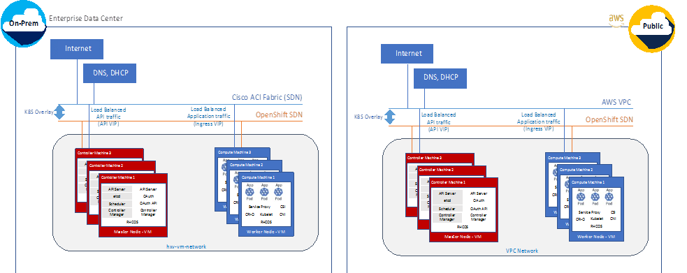
For communication outside the cluster, OCP provides services (node ports, load balancers) and API resources (Ingress, Route) to expose an application or a service outside cluster so that users can securely access the application or service running on the OCP cluster. API resources, Ingress and Routes are used in this solution to expose the application deployed in the OCP cluster.
VMware vSphere CSI
Storage vendors have traditionally provided storage drivers as part of Kubernetes. With the implementation of the Container Storage Interface (CSI), third-party providers can instead deliver storage plugins using a standard interface without ever having to change the core Kubernetes code.
CSI Operators give OpenShift Container Platform users storage options, such as volume snapshots, which are not possible with in-tree volume plugins.
The vSphere CSI Operator Driver storage class uses vSphere’s storage policy. OpenShift Container Platform automatically creates a storage policy to access datastores through the vSphere CSI. The datastores in this solution are provided by the underlying HyperFlex HXDP storage. The vSphere storage deployed automatically during the Red Hat OCP deployment is known thin-csi with the default configuration as shown below.
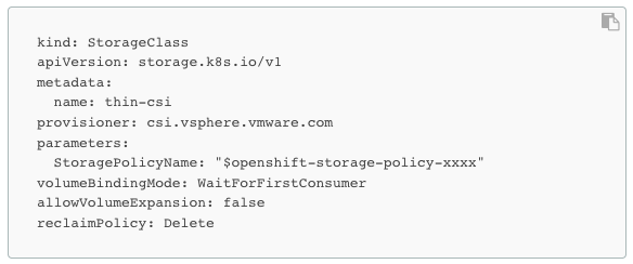
In the Red Hat OCP version used to validate this solution, the install process deploys both the vSphere in-tree (non-CSI) and out-of-tree CSI driver as shown in the figure below. The solution will use the CSI driver (thin-CSI) as Kubernetes community generally recommends CSI drivers and for storage, it provides capabilities such as volume snapshots that are critical for protecting application data.
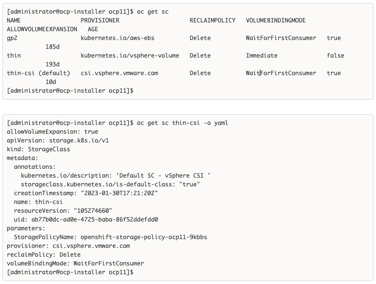
To enable volume snapshots, the K8S administrator will still need to define a volume snapshot class such as the one below.
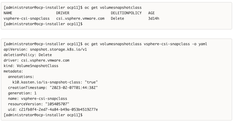
With the vSphere CSI driver deployed and volume snapshot class configured, any application workload deployed on the on-prem OCP cluster dynamically request and provision storage from the underlying Cisco HyperFlex storage through VMware vSphere CSI using native K8S objects such as Persistent Volume Claim and Persistent Volumes.
Kasten K10 by Veeam
Kasten K10 is a production-grade data management platform that is leveraged in this solution to support hybrid cloud use cases such as Backup/Restore and Application Mobility. Kasten K10 provides a common data management solution that spans both on-prem and public cloud, integrating seamlessly with several on-prem and public cloud infrastructure and storage options - including Red Hat OCP, Cisco HyperFlex, VMware vSphere, and AWS, as used in this hybrid cloud solution. Kasten K10 can be quickly deployed on an OpenShift cluster using a Helm chart or the Level 3 Certified Operator available from the Red Hat Marketplace directly accessible from the OCP cluster console.
Kasten K10 provides several capabilities that are integral for a production Kubernetes deployment. Some of the key features that Enterprises can leverage are:
● K10 Multi-Cluster Manager
The K10 multi-cluster manager simplifies K10 operations across multiple Kubernetes clusters. Administrators define primary-secondary relationships between their K10 instances. Primary K10 instances provide a single-entry point and dashboard for administrators to manage secondary instances. K10 resources, like Policies and Profiles, can be centrally defined distributed to secondary clusters. Secondary instances enact their policies and the secondaries' actions, and metrics are summarized in the primary instance.
● Authentication and RBAC
Kasten K10 supports multiple authentication mechanisms. Options include Direct Access, Basic Authentication, Token-based (AWS IAM, Red Hat OCP), OpenID Connect, OpenShift OAuth, and Active Directory. This solution will use OpenID Connect Authentication.
As a Kubernetes-native application, Kasten K10 leverages Kubernetes RBAC objects which can be used to create secure, multi-tenant access to a single cluster across multiple teams, roles, and applications.
See the Kasten documentation for additional information.
● Metadata Transform Engine
Kasten K10 provides a wide set of capabilities that can be used to add, remove, or alter application metadata during the restore process. Transforms are a necessity when restoring applications in a DR scenario, cloning application namespaces for use cases such as dev/test, or migrating applications between different clusters. For instance, a common transform would be to alter to StorageClass assigned to a PVC when restoring to a cluster using different storage infrastructure as your source. Other uses include altering numbers of replicas, adding annotations or labels, and updating Route or Ingress objects. Automating these metadata changes as part of the restore process provides a consistent restore experience and can significantly lower RTO during a disaster.
● Customized Application Backups using Blueprints
Kasten K10 defaults to volume snapshot operations when capturing data, but distributed, cloud native applications require more stringent and consistent logical or system data protection operations, which often rely on orchestration with application and infrastructure maintenance tools and APIs. Kasten K10 includes Kanister, an open source, extensible data management framework. Kanister provides Blueprints for several popular applications, including several database workflows. When configured, K10 will use Kanister Blueprints for operations.
Kanister Blueprints are YAML, simple to create, and existing Blueprints are easy to customize. Blueprints typically require no application modification because many are written to work with application Helm Charts and Operators. The [Kanister public Git repository](https://github.com/kanisterio/kanister/tree/master/examples) contains many community supported Blueprints.
● Application-Consistent Backups
For backups that require working with the data service, above the underlying infrastructure, Kanister provides blueprints for the following database applications running on OpenShift clusters:
◦ Logical MySQL Backup for OpenShift
◦ Logical MongoDB Backup on OpenShift clusters
◦ Logical PostgreSQL Backup on OpenShift Clusters
Backups can be also performed for managed services such as Amazon RDS using blueprints (for example: AWS RDS PostgreSQL Backup) using the snapshot APIs of the service or CLI tooling.
Further control can be taken with application-consistent backups which orchestrate operations, such as quiescing functions to flush memory to storage, before and after using data service and/or the volume snapshot process.
The following examples for application-consistent backups are available today:
◦ Application-Consistent MongoDB Backup
◦ Application Consistent PostgreSQL Backup
◦ Application Consistent PostgreSQL HA Backup and Restore
● System consistent backup orchestration across multiple applications and databases on the same cluster can be addressed, see Kasten and Kanister documentation for additional information.
● Backup and Restore of etcd
If a backup of all cluster state stored in etcd is required, the etcd cluster can be backed up and restored in case of catastrophic failure:
etcd Backup (Kubeadm)
etcd Backup (OpenShift Container Platform)
● Pre-Flight Checks
Kasten K10 provides a primer tool for doing a pre-flight check of the Kubernetes deployment before deploying Kasten K10. This tool runs in a Pod in the cluster and does the following:
◦ Validates if the Red Hat OCP cluster settings meets K10 requirements.
◦ Creates and then cleans up a ServiceAccount and ClusterRoleBinding to perform sanity checks on the OCP cluster
◦ Catalogs the available storage classes. When using a CSI as in this solution, it will also do a basic validation of the cluster's CSI capabilities and any relevant objects that may be required.
For a more complete CSI validation, the primer tool can be run with a specified storage class that will do the following:
◦ Creates a sample application with a persistent volume and writes some data to it
◦ Takes a snapshot of the persistent volume
◦ Creates a new volume from the persistent volume snapshot
◦ Validates the data in the new persistent volume
Table 3 lists the hardware components used for validating the solution.
Table 3. Solution Components - Hardware
| Component |
Hardware |
| Hyperconverged Servers |
4 x Cisco HXAF220C-M5SX for application workload cluster (additional 4 for an optional management cluster) |
| Fabric Interconnects |
Two (2) Cisco UCS 6332 Fabric Interconnects |
| Data Center Fabric |
Cisco ACI Fabric with 3 x APIC, 2 x Spine switches (N9k-C9332C), 2 x Leaf switches (N9K-C9336C-FX2), additional Leaf switches for optional management cluster. |
| External Gateways |
2 x CSR 1000vs for IPsec VPN to AWS |
Table 4 lists the software components and the versions used for validating the solution.
Table 4. Solution Components - Software
| Component |
Software |
| Cisco HyperFlex Data Platform Software |
5.0(2b) |
| Red Hat OpenShift Container Platform (OCP) |
4.10 |
| Kasten K10 |
5.5.4 |
| VMware vSphere |
7.0 Update 3i (Build: 20842708) |
| VMware vCenter |
7.0 Update 3i (Build: 20845200) |
| VMware vSphere CSI |
2.4.1 (depends on Red Hat OCP version) |
| Cisco UCS Firmware |
4.2(2d) |
| Cisco ACI Software |
5.2(4d) |
| SaaS - Cisco Intersight |
N/A |
| SaaS – Red Hat Hybrid Cloud Console |
N/A |
| SaaS – Cisco Intersight Workload Optimizer |
N/A (Cisco IWO Collector on OCP cluster: v1.20) |
| Public Cloud - AWS |
N/A |
This chapter contains the following:
● Deploy Cisco HyperFlex Virtual Server Infrastructure
● Deploy Red Hat OpenShift Container Platform (On-Prem)
● Deploy Red Hat OpenShift Container Platform (Public Cloud)
● Enable Secure Hybrid Cloud Connectivity
● Enable Volume Snapshots using Kasten and VMware vSphere CSI (On-Prem)
● Deploy Kasten K10 (Public Cloud)
● Verify Volume Snapshot Class Configuration (Public Cloud)
● Enable Volume Snapshots using Kasten and AWS CSI (Public Cloud)
● Enable Cisco Intersight Workload Optimizer (On-Prem)
● Enable Cisco Intersight Workload Optimizer (Public Cloud)
This chapter describes the solution deployment with step-by-step procedures for implementing and managing the solution.
At a high-level, the solution deployment can be split into the following areas:
● Deploy on-prem infrastructure
● Deploy public cloud infrastructure
● Enable secure interconnectivity between on-prem and public cloud infrastructure
On-Prem Infrastructure
In the on-prem data center, Enterprises typically manage their own compute, storage, and networking. To accelerate application efforts, we want to deploy this infrastructure as quickly as possible. In cloud-native environments, it is also critical to provide infrastructure as code for integration into CI/CD and other automation that an Enterprise has.
The deployment of the on-prem infrastructure consists of:
● Deploy networking to enable reachability for remaining components in the infrastructure stack. Red Hat Ansible provisions the network infrastructure as code.
● Deploy compute, storage, virtualization, and networking for server/virtual machines. The VSI cluster serves as an Applications cluster for hosting cloud-native workloads. Red Hat Ansible automates the hyperconverged infrastructure deployment using Cisco Intersight APIs to claim, provision and deploy a complete virtual server infrastructure platform.
● Deploy Red Hat OpenShift Container Platform to enable a cloud-native application development environment
● Deploy Cisco HyperFlex Container Storage Interface as persistent storage for cloud-native workloads
● Enable resource optimization of on-prem resources using Intersight Workload Manager to ensure application performance.
Public Cloud Infrastructure
Since the public cloud provider manages the compute, storage and networking infrastructure, the deployment of the public cloud infrastructure is limited to:
● Deploy Red Hat OpenShift Container Platform. The automated installer for Red Hat OCP will take care of deploying the infrastructure resources required to host the OCP cluster (for example, AWS VPC, EC2 instances).
● Enable resource optimization of public cloud resources using Intersight Workload Manager to ensure application performance and manage cloud costs.
Secure Hybrid Cloud Connectivity Infrastructure
To securely interconnect the two environments in the hybrid cloud deployment involves the following:
● Provision public cloud for secure connectivity to the on-prem location
● Provision on-prem infrastructure for secure connectivity to the public location
This section describes the deployment of the on-prem network infrastructure in this hybrid cloud solution. The on-prem network in this solution is a Cisco ACI fabric managed using Cisco APIC. The deployment is automated using Red Hat Ansible playbooks available in the Cisco UCS Solutions GitHub repository. The automation will focus on the day-2 networking required to support the infrastructure and workloads in the solution.
Assumptions
The deployment procedures outlined in this section makes the following assumptions:
● Enterprise has an existing Cisco ACI fabric - the on-prem hybrid cloud infrastructure in this solution will connect into this fabric.
● Day-0 and day-1 provisioning of the above ACI fabric is complete, with internal and external connectivity to services in place – for example, Internet access and services such as DNS, DHCP.
● Management infrastructure with the necessary connectivity is available for hosting an automation workstation. The workstation will need reachability to the Internet and Cisco APIC cluster managing the ACI fabric.
Prerequisites
The prerequisites for provisioning the network are:
● The Cisco ACI Fabric leaf switches that the application Cisco HyperFlex cluster and Cisco UCS Fabric Interconnects connect to should be deployed and provisioned to be part of the ACI fabric.
● Application Cisco HyperFlex cluster servers and the Cisco UCS Fabric Interconnects should ideally be physically cabled, powered, and connected to the ACI fabric so that connectivity can be verified when the network provisioning is complete.
● Ansible control node or workstation for executing the Ansible playbooks. The playbooks automate the day-2 provisioning of the networking required to bring the cloud-native infrastructure up.
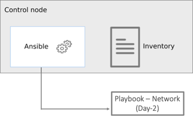
Setup Information
Table 5 lists the configuration parameters.
Table 5. Cisco ACI - Configuration Parameters
| Variable |
Variable Name |
Value |
Additional Info |
| Cisco APIC cluster |
- |
172.26.163.120 |
<Login Credentials> |
| Git Hub Repo |
- |
https://github.com/ucs-compute-solutions/Hybrid-Cloud/tree/main/CVD_HC-OCP-HXFI Ansible scripts for provisioning the ACI fabric is in the network directory. |
|
| Other |
|
All variables required to execute the Ansible scripts are defined in the file below, located in a separate directory called inventory in the above repo: inventory > group_vars > cisco_dc_fabric |
|
This section describes the procedures for configuring the day-2 networking required to connect and deploy the application Cisco HyperFlex VSI cluster. The application cluster connects to a pair of Cisco UCS Fabric Interconnects that is dual-homed to a pair of leaf switches in the data center fabric.
Procedure 1. Prerequisite – Setup an Ansible Control Node running MacOS
Note: The Ansible workstation is running MacOS in this setup.
To install on other operating systems: https://docs.ansible.com/ansible/latest/installation_guide/installation_distros.html
For additional information, see the Ansible Installation Guide: https://docs.ansible.com/ansible/latest/installation_guide/intro_installation.html#
Step 1. Ansible control node requires Python 3.8 or higher. Verify if it is already installed.
$ python3 -V
![]()
Step 2. If Python is not installed or needs to be upgrade, use the commands below to install it.
$ brew install python3
-OR-
$ brew upgrade python3
Step 3. Verify if you have the Python package manager (pip). The above python install should automatically install pip.
$ python3 -m pip -V
![]()
Step 4. If pip is not installed or needs to be upgraded, use the following commands
$ curl https://bootstrap.pypa.io/get-pip.py -o get-pip.py
$ python3 get-pip.py
-OR-
$ pip3 install --upgrade pip
Step 5. (Optional) Create Virtual Environment (venv) using Python and activate it for use.
$ python3 -m venv <venv_name>
$ python3 -m venv venv1
$ source ./venv1/bin/activate
To deactivate: deactivate
Create aliases (example): alias switchto_venv=‘source ./venv1/bin/activate’
Step 6. Install Ansible on workstation in virtual environment (optional); other useful commands also provided
(venv1)$ pip install ansible # not necessary to specify python version in venv
(venv1)$ which ansible
(venv1)$ ansible –-version
(venv1)$ ansible –h
(venv1)$ pip install –-upgrade ansible
Step 7. Verify the path and version of python is what you want Ansible to use
(venv1)$ ansible –-version
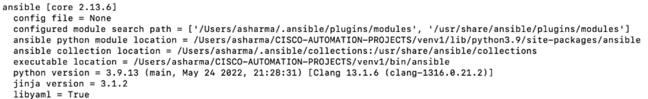
Step 8. Install GIT. It might already be installed on MacOS through other tools. Otherwise install git as follows:
(venv1) $ brew install git # not necessary to execute this in venv
Procedure 2. Clone Git Hub repository for network provisioning
To access the Ansible playbooks in the GitHub repository (repo), clone the Git Hub repo as outlined below. The cloning will create a completely new copy of the repo in the location specified on the Ansible workstation. The repo is located at: https://github.com/ucs-compute-solutions/Hybrid-Cloud directory.
Step 1. On the Ansible workstation, use a terminal console or command-line tool to create a directory for the project. The GitHub repo will be cloned to a sub-directory in this directory. For example, if the directory is CISCO-AUTOMATION-PROJECTS, the repo will be cloned within this directory under a sub-directory.
Step 2. Navigate to the newly created directory from the terminal window and execute the following command:
git clone https://github.com/ucs-compute-solutions/Hybrid-Cloud.git
Step 3. Navigate to the sub-directory (CVD_HC-OCP-HXFI), followed by the network directory below that (network).
Step 4. (Optional) Switch to the Python virtual environment using the command provided in the Setup Ansible Control Node deployment procedure earlier in the document.
Procedure 3. Review the Ansible files for provisioning the network
Ansible uses inventory files (inventory.ini, inventory.yml), variables files (group_vars, host_vars), and playbooks to automate the provisioning. The inventory files are the targets of the automation, in this case, the Cisco APICs managing the Cisco ACI Fabric. It will have information to connect to the target device. The variables files contain the configuration parameters. The inventory files and variable files will need to be modified for each environment.
Step 1. Review inventory, variables, and playbooks for provisioning the network. The Ansible playbooks for provisioning the network infrastructure and the associated inventory and variables are highlighted in the figure below.
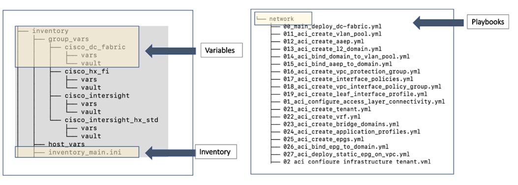
Note: The playbooks are in the ‘network’ sub-directory under ‘CVD_HC-OCP-HXFI.’ The variables and inventory are in the same ‘inventory’ sub-directory under ‘CVD_HC-OCP-HXFI,’ in ‘group_vars’ directory and ‘inventory_main.ini’ file, respectively.
Step 2. Review the main playbook file for network provisioning. Note that at a high-level, the main playbook consists of:
● Authenticating with Cisco APIC to provision the ACI fabric. Authentication information is encrypted using Ansible vault and referenced in the variable files and in the playbook as shown below.
● Configuring the access layer connectivity to Cisco UCS FI and Cisco HyperFlex servers to provision and bring up the VPC/PC configuration between Cisco UCS Fabric Interconnects and Nexus 9000 series leaf switches.
● Configuring the ACI Tenant constructs and policies (Tenant, VRFs, Bridge Domains, Application profiles, EPGs, Contracts) that enable connectivity through the ACI fabric for the application Cisco HyperFlex VSI cluster connected to it.
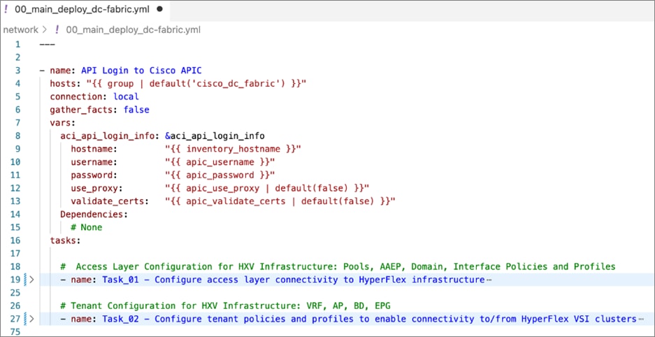
Note: The playbook tasks are named to reflect their hierarchy within the within the overall collection of playbooks. The main task is numbered as 00_ , with the two tasks below it as 01_ and 02_ . The sub-tasks within each of these are then numbered starting with 011_ and 021_ respectively.
Procedure 4. Modify the variables files for executing the Ansible playbooks
To execute the playbook file, the Ansible variables file is populated with the parameters that will be used to configure the network fabric. The configuration variable names, and the parameters used in this solution are provided in Table 6. You can use either a text editor or an IDE environment (for example, Microsoft Visual Studio Code) to edit the variables file.
Note: The variables and parameters in the table below, is not a comprehensive list – it shows the parameters that are environment specific that the Enterprise administrator must provide and few additional ones.
Table 6. Access Layer Configuration Parameters
| Variable |
Variable Name |
Value |
Additional Info |
| VLAN |
hxv-inband-mgmt |
1171 |
Cisco HyperFlex iband-management – SCVM, ESXi |
| VLAN |
hxv-cl3-storage-data |
1273 |
Cisco HyperFlex storage data – SCVM, ESXi |
| VLAN |
hxv-vmotion |
1371 |
Cisco HyperFlex vMotion |
| VLAN |
hxv-vm-network |
1521-1530 |
|
| VPC |
protection_group_id |
12 |
VPC ID |
| Leaf switch ID |
switch_1_id |
103 |
VPC Leaf switch pair |
| Leaf switch ID |
switch_2_id |
104 |
VPC Leaf switch pair |
| Interface Policies |
cdp_policy_name |
CDP_Enabled |
|
|
|
link_level_policy_name |
40Gbps-Link |
|
|
|
lldp_policy_name |
LLDP-Enabled |
|
|
|
port_channel_policy_name |
LACP-Active |
|
|
|
l2_interface_policy_name |
VLAN-Scope-Local |
|
|
|
stp_interface_policy_name |
BPDU-FG-Enabled |
|
| Leaf Selector |
HXV-UCS_FI-Leaf_103-104 |
103,104 |
switch_1_id, switch_2_id |
| Leaf Access Port Selectors |
HXV-FI_p1_1 |
1/1 |
|
|
|
HXV-FI_p1_1 |
1/2 |
|
Table 7 lists the ACI tenant networking constructs that enable forwarding through the fabric.
| Variable |
Variable Name |
Value |
Additional Info |
| Tenant Name |
Tenant |
HXV-Foundation |
|
| VRF Name |
VRF |
HXV-Foundation_VRF |
|
| Bridge Domain |
HXV-IB-MGMT_BD |
|
Cisco HyperFlex iband-management |
| Gateway IP address |
gateway |
10.1.171.254 |
|
| Gateway Netmask |
mask |
255.255.255.0 |
|
| Bridge Domain |
HXV-CL3-StorData_BD |
|
Cisco HyperFlex storage-data |
| Bridge Domain |
HXV-vMotion_BD |
|
Cisco HyperFlex vMotion |
| Application Profile |
HXV-IB-MGMT_AP |
|
Cisco HyperFlex iband-management |
|
|
HXV-CL3-StorData_AP |
|
Cisco HyperFlex storage-data |
|
|
HXV-vMotion_AP |
|
Cisco HyperFlex vMotion |
| EPG |
HXV-IB-MGMT_EPG |
|
Cisco HyperFlex iband-management |
|
|
HXV-CL3-StorData_EPG |
|
Cisco HyperFlex storage-data |
|
|
HXV-vMotion_EPG |
|
Cisco HyperFlex vMotion |
| Contracts |
Allow-Common-L3Out_Contract |
|
Existing contract – allows access to any network outside the ACI fabric – Internet, other Enterprise internal networks |
|
|
Allow-IB-MGMT_Contract |
|
Allows access to Cisco HyperFlex and ESXi hosts in the cluster |
|
|
Allow-INFRA-MGMT_Contract |
|
Allows access to VMware vCenter and other infrastructure management services running on the Management cluster |
Note: The above tables only show a subset of the configuration parameters required to enable forwarding of Cisco HyperFlex VSI traffic to other nodes in the cluster, to the Internet, to out-of-band networks and so on. For a complete list, see variables file in GitHub repository
Procedure 5. Execute the main playbook for provisioning the network infrastructure
Step 1. Identify the main playbook file in the network sub-directory. This main YAML file have a name that starts with ‘00_’.
Step 2. Identify the path to the inventory file relative to where you will run the playbook
Step 3. Run the main playbook to configure networking: ansible-playbook <playbook-name> -i <inventory_file_name>
(venv1)CVD_HC-OCP-HXFI $ ansible-playbook network/00_main_deploy_dc-fabric.yml -i inventory/inventory_main.ini
Procedure 6. Verify the deployed configuration
Step 1. Login to web GUI of the Cisco APIC cluster managing the ACI fabric.
Step 2. To verify the access layer setup to Cisco UCS Fabric Interconnects and Application Cisco HyperFlex cluster in the ACI Pod (in this case, Pod1) it connects to. Navigate to Fabric > Inventory > Pod 1 and select the leaf switch and interface for the connection. Verify that it is up and operational with correct LLDP/CDP neighbor. Ignore the VLAN info as they ACI internal VLANs. You can also view the EPGs deployed on the interface.
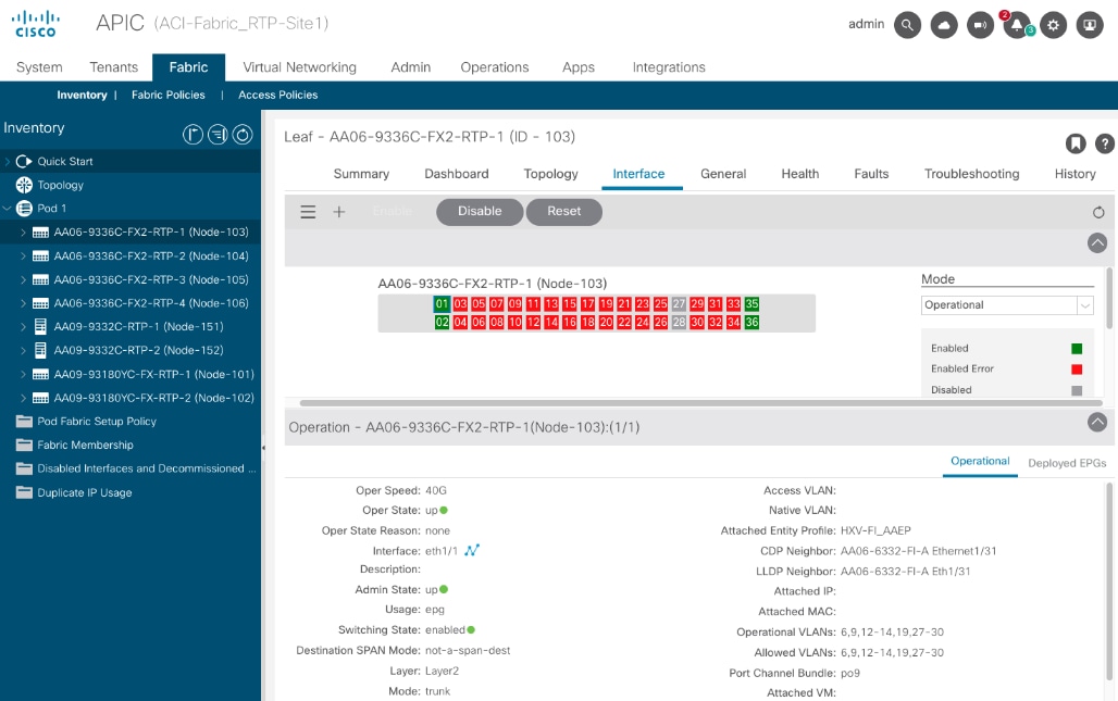
Step 3. Select the Deployed EPGs tab to see the EPGs deployed on the interface. Repeat for all interfaces on this leaf switch and the second switch in the pair.
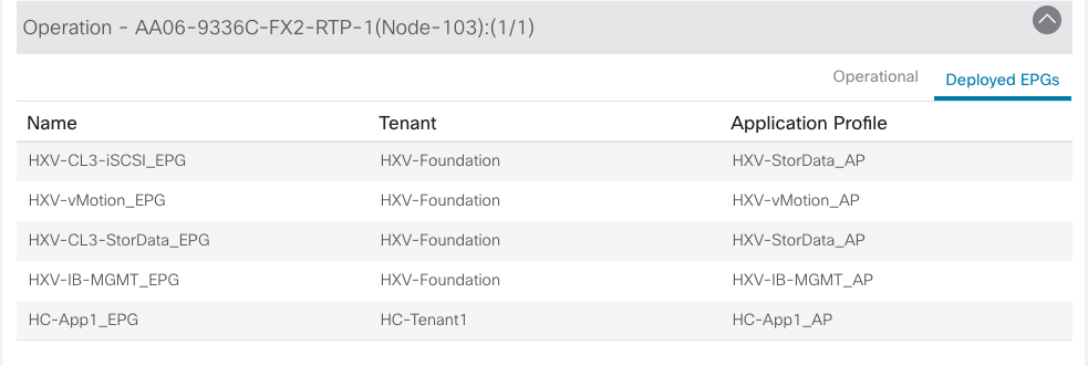
Step 4. You can also verify that there are no faults in the access layer policies by starting with the switch profile that includes all the policies associated with a subset of leaf interfaces on a specific leaf. Navigate to Fabric > Access Policies > Switches > Leaf Switches > Profiles and find the profile that defines the access layer configuration to the Cisco UCS FI and Cisco HyperFlex. Verify that there are no faults. Use this as a starting point to verify that there are no faults in all the policies and selector profiles that this profile uses. From the profile, you can click a policy to navigate to it.
Step 5. To verify the configuration and status of the ACI constructs that enable connectivity through the fabric (Tenant, VRF, Application Profile, BD, EPG, Contracts, and so on), navigate to Tenants > HXV-Foundation and verify that there are no faults or errors for each of the above constructs.
Step 6. Verify the contracts by testing reachability to the Internet, VMware vCenter managing the vSphere cluster and other Enterprise internal networks (for example, out-of-band management interface on Fabric Interconnects and KVM IP of servers)
The network is now ready for deploying the Cisco HyperFlex VSI infrastructure as outlined in the next section.
Deploy Cisco HyperFlex Virtual Server Infrastructure
This section describes the deployment of the on-prem virtual server infrastructure in this hybrid cloud solution. The on-prem infrastructure in this solution is a Cisco HyperFlex VSI running VMware vSphere, deployed, and managed using Cisco Intersight. The deployment is automated using Red Hat Ansible playbooks available in the GitHub repository for Cisco UCS Solutions. The automation will focus on day-0 and day-1 deployment of a new Cisco HyperFlex VSI cluster for hosting cloud-native applications.
Assumptions
The deployment outlined in this section assumes the following:
● Enterprise has an existing management Cisco HyperFlex cluster in place to host infrastructure and management components required in this solution.
● For purposes of this document, the management cluster is a Cisco HyperFlex VSI cluster. The deployment of this cluster will not be covered in this document. It is connected to the same Cisco ACI fabric through a different Cisco UCS domain. It will be in the same HXV-Foundation tenant and share the same in-band management and vMotion network as the application Cisco HyperFlex cluster discussed here.
● For accessing the infrastructure services hosted on the management cluster, ACI fabric exposes a contract (Allow-INFRA-MGMT_Contract) that is used by the application VSI cluster to enable reachability between the two. The contract enables VMware vCenter running on the management cluster to manage the application VSI cluster. It also hosts the DNS, DHCP, Red Hat OCP installer for deploying the Application OCP cluster.
The deployment procedures outlined in this section will therefore focus on deploying the Cisco HyperFlex “Application” or workload cluster for hosting cloud-native applications.
Prerequisites
The prerequisites for the Cisco HyperFlex VSI deployment are:
● Cisco data center fabric is provisioned to provide the infrastructure connectivity required to deploy a Cisco HyperFlex cluster.
● Network services (DNS, NTP) and VMware vCenter are available and reachable from the Application HyperFlex cluster and Cisco Intersight.
● Application HyperFlex server and Cisco UCS Fabric Interconnects are physically cabled, powered, and connected to the ACI fabric leaf switch pair.
● Ansible control node or workstation for executing the Ansible playbooks.
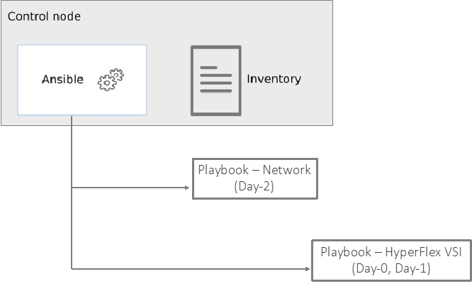
Setup Information
Table 8 lists the installation parameters.
Table 8. Cisco HyperFlex - Installation Parameters
| Variable |
Variable Name |
Value |
Additional Info |
| Cisco UCS Manager IP and Login Credentials |
- |
192.168.171.192 |
<Login Credentials> |
| Intersight Account & Login |
- |
<collect> |
|
| Cisco UCS Manager FI – Claim Code |
- |
<collect> |
|
| Cisco UCS Manager FI – Device ID |
- |
<collect> |
|
| Git Hub Repo |
- |
https://github.com/ucs-compute-solutions/Hybrid-Cloud/tree/main/CVD_HC-OCP-HXFI Ansible scripts for provisioning the Cisco HyperFlex VSI is in the compute directory. |
|
| Other |
|
All variables required to execute the Ansible scripts are defined in the files below, located in a separate directory called inventory in the above repo: inventory > group_vars > cisco_hx_fi inventory > group_vars > cisco_intersight inventory > group_vars > cisco_intersight_hx_std_servers |
|
Deployment Steps
This section describes the procedures for deploying an Application HyperFlex VSI cluster. The application cluster connects to a pair of Cisco UCS Fabric Interconnects that is dual-homed to a pair of leaf switches in the data center fabric. A built-in installer on Cisco Intersight will remotely deploy the cluster. The Ansible automation will provide the necessary configuration parameters and initiate the install of a Cisco HyperFlex VSI cluster using Cisco Intersight. The parameters provided are the same as the inputs to the installer wizard on Intersight GUI.
To deploy a Cisco HyperFlex cluster using Intersight, the Cisco UCS Fabric Interconnects that the Cisco HyperFlex servers connect to must be first claimed in Cisco Intersight. The Ansible script provided will use the Cisco UCS FI and Intersight information in the Ansible inventory file to:
● Connect to the out-of-band management interfaces on Cisco UCS FI
● Collect the Claim Code and Device ID
● Connect to Cisco Intersight
● Claim the Cisco UCS Fabric Interconnects as targets in Cisco Intersight
Once the FI is claimed, Intersight will discover the Cisco HyperFlex servers connected to it. The script will then use the server information to dynamically update the Ansible inventory file. A dummy inventory item must be provided as a placeholder in the inventory file to enable the dynamic inventory update. Ansible and Cisco Intersight will use the Cisco HyperFlex server information to deploy and provision the Cisco HyperFlex VSI cluster. The script also provides an option to (1) validate the provided configuration (without deploying) or (2) validate and deploy the configuration.
Once the install is kicked off, status of the install can be monitored directly from Intersight. The install itself will take some time (< 1 hour) to complete but most of it is unattended. If any failures occur, the install will stop, and you will have to address the issue and restart from Intersight. The script currently does not have the ability to restart a stalled install. If you have met all the pre-requisites outlined in the Cisco documentation and the pre-install validation checks were successful with no errors/warnings, then the install should complete successfully.
Note: The Cisco HyperFlex VSI install will implement best practices and deliver a fully-functional, hyper-converged virtual server infra platform that is ready for deploying applications, either traditional or cloud-native, making it simple and easy for IT and DevOps team to quickly spin up a new environment with compute and storage. The cluster can also be easily expanded, upgraded (full-stack) and generally managed post-deployment from Cisco Intersight.
Procedure 1. Prerequisite – Setup an Ansible Control Node running MacOS
The steps for configuring this and additional information is explained in the Solution Deployment > Provision Network Infrastructure > Deployment Steps section of this document.
Procedure 2. Clone Git Hub repository for Cisco HyperFlex VSI deployment
To access the Ansible playbooks in the GitHub repository (repo), clone the Git Hub repo as explained in the Solution Deployment > Provision Network Infrastructure > Deployment Steps section of this document. Skip this if you’ve already done this for accessing the Ansible network scripts.
The repo is located here: https://github.com/ucs-compute-solutions/Hybrid-Cloud/ in a sub-directory called CVD_HC-OCP-HXFI. The cloning will generate a local copy of the repo in GitHub. The Cisco HyperFlex VSI scripts will be in a sub-directory called ‘compute.’
Procedure 3. Create Intersight API Keys for API authentication
To use Ansible playbooks to deploy the cluster from Cisco Intersight, Ansible needs API access to Intersight. This access is enabled through Intersight API keys (API Key ID, Secret Key). The API Key ID is visible and available after the initial key creation. The secret key is an RSA Private Key, and it is only available at API Key creation so it should be saved in a secure location.
Step 1. Use a web browser and navigate to Intersight.com. Login using an admin account.
Step 2. Select System from the drop-down list in the top left-hand side of the Intersight GUI.
Step 3. Select and click API Keys in the left-hand navigation pane.
Step 4. Click Generate API Key button on the upper-right side of the window.
Step 5. In the Generate API Key pop-up window, enter a Description for the key, select the radio button for API key for OpenAPI schema version2 radio button, and click Generate.
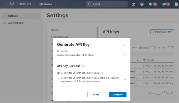
Step 6. Click the icon to copy the API Key ID and update the API Key ID variable int in the inventory/group_vars/cisco_intersight/vault file. The vault will be encrypted, and the Key ID will be referenced by a variable in the inventory/group_vars/cisco_intersight/vars file for use by the playbook tasks as shown below.
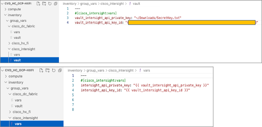
Step 7. Click the icon to save the Secret Key to text file. Rename and save the file in a secure location. Update the private key variable in inventory/group_vars/cisco_intersight/vault file. The secret key will be referenced by a variable in the inventory/group_vars/cisco_intersight/vars file for use by the playbook tasks.
Procedure 4. Review the Ansible files for Cisco HyperFlex VSI deployment
Ansible uses inventory files (inventory.ini, inventory.yml), variables files (group_vars, host_vars), and playbooks or scripts to deploy a Cisco HyperFlex VSI cluster using the inventory and input variables provided. The inventory files are the targets of the automation which in this case are Cisco UCS FI (for claiming the servers) and Intersight (t deploy and manage the cluster). Inventory will provide information to connect to the target device. The variables files contain the configuration parameters. The inventory files and variable files will need to be modified for each environment and deployment.
Step 1. Review inventory, variables, and playbooks for deploying a Cisco HyperFlex VSI cluster. The Ansible playbooks and the associated inventory and variables are highlighted in the figure below.
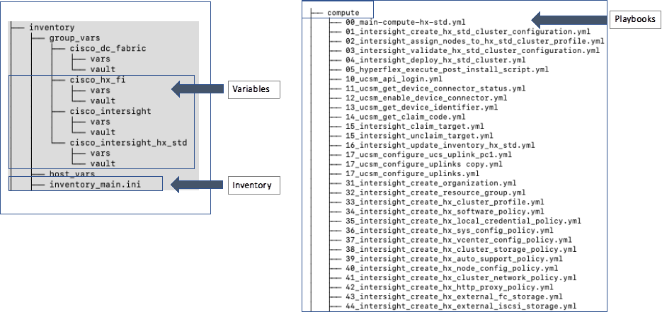
The playbooks are in the ‘compute’ sub-directory under ‘CVD_HC-OCP-HXFI.’ The variables and inventory are in the same ‘inventory’ sub-directory under ‘CVD_HC-OCP-HXFI,’ in ‘group_vars’ directory and ‘inventory_main.ini’ file, respectively.
Step 2. Review the main playbook file for deploying a Cisco HyperFlex VSI cluster. Note that at a high-level, the main playbook consists of:
● Authenticating with Cisco UCS Manager and Cisco Intersight. Authentication information is encrypted using Ansible vault and referenced in the variable files and in the playbook as shown below.
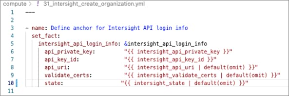
● Connect to Cisco UCS Manager and collect device claim info
● Connect to Cisco Intersight and claim device, update Ansible inventory with Cisco HyperFlex server info
● Validate and deploy Cisco HyperFlex VSI from Cisco Intersight
Step 3. The playbook tasks are named to reflect their hierarchy within the overall collection of playbooks. The main task is numbered as 00_ , with the first-level tasks below it as 01_ and 02_ . The sub-tasks or the second-level within each are then numbered starting with 011_ and 021_ and so on.
Procedure 5. Modify the variables files for executing the Ansible playbooks
To execute the playbook file, the Ansible variables file is populated with the parameters that will be used to deploy the Cisco HyperFlex VSI cluster within the overall collection of playbooks. The configuration variable names, and the parameters used in this solution are provided in Table 9. You can use either a text editor or an IDE environment (for example, Microsoft Visual Studio Code) to update the variables file.
Table 9. Cisco HyperFlex VSI Cluster Configuration
| Variable Type |
Variable |
Value |
Additional Info |
| VLAN |
hxv-inband-mgmt |
1171 |
Cisco HyperFlex iband-management – SCVM, ESXi |
| VLAN |
hxv-cl3-storage-data |
1273 |
Cisco HyperFlex storage data – SCVM, ESXi |
| VLAN |
hxv-vmotion |
1371 |
Cisco HyperFlex vMotion |
| VLAN |
hxv-vm-network |
1521-1530 |
|
| KVM |
Starting IP |
192.168.171.111 |
|
|
|
Ending IP |
192.168.171.114 |
|
|
|
Subnet Mask |
255.255.255.0 |
|
|
|
Gateway |
192.168.171.254 |
|
| Jumbo Frames |
N/A |
Yes |
|
| DNS, NTP and Timezone |
Timezone |
America/New_York |
|
|
|
DNS Suffix |
hc.com |
|
|
|
DNS Server (s) |
192.168.171.240 |
|
|
|
NTP Server(s) |
192.168.171.254 |
|
| Auto Support |
Auto-Support |
Yes |
|
|
|
Send Service Ticket Notification to |
hc-admin@xyz.corp |
|
| Node IP Ranges |
Management Network Starting IP |
10.1.171.111 |
|
|
|
Management Network Ending IP |
10.1.171.114 |
|
|
|
Management Network Subnet Mask |
255.255.255.0 |
|
|
|
Management Network Gateway |
10.1.171.254 |
|
|
|
SCVM Network Starting IP |
10.1.171.161 |
|
|
|
SCVM Network Ending IP |
10.1.171.164 |
|
| Storage Configuration |
VDI Optimization |
No |
|
|
|
Logical Availability Zones |
No |
|
| vCenter |
vCenter Server FQDN or IP |
vc1-1.hc.com |
|
|
|
vCenter Username |
administrator@vsphere.local |
|
|
|
vCenter Password |
•••••••••••••• |
|
|
|
vCenter Datacenter Name |
HC-App-Site1 |
|
| Security |
Hypervisor Admin |
root |
|
|
|
The hypervisor on this node uses the factory default password |
Yes |
|
|
|
Hypervisor Password |
•••••••••••••• |
|
|
|
Controller VM Admin Password |
•••••••••••••• |
|
| Cluster Profile |
Profile Name |
HC-CL3 |
|
|
|
Profile Description |
|
|
|
|
Cisco HyperFlex Management Platform |
FI |
|
|
|
Cisco HyperFlex Hypervisor Type |
ESXi |
|
|
|
Cisco HyperFlex Management IP |
10.1.171.110 |
|
|
|
Cisco HyperFlex MAC Prefix |
00:25:B5:03 |
|
|
|
Cisco HyperFlex WWXN Prefix |
20:00:00:25:B5:03 |
|
|
|
Cisco HyperFlex Replication Factor |
3 |
|
The deployment will result in the following policies and profiles in Cisco Intersight:
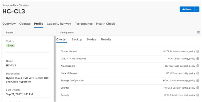
Procedure 6. Execute the main playbook to deploy the Cisco HyperFlex VSI cluster
Step 1. Identify the main playbook YAML file in the compute sub-directory. This main playbook will have ‘00_’ in the name.
Step 2. Identify the path to the inventory file relative to where you will run the playbook
Step 3. Run the main playbook to deploy Cisco HyperFlex VSI: ansible-playbook <playbook-name> -i <inventory_file_name>
(venv1)CVD_HC-OCP-HXFI $ ansible-playbook compute/00_main_deploy_hx-std.yml -i inventory/inventory_main.ini
Step 4. The high-level tasks in the main playbook for Cisco HyperFlex VSI is shown below:
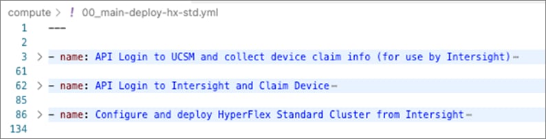
Step 5. At some point during the playbook execution, the script will prompt you for a deployment action i.e., [1] Validate Only (without deploying) or [2] Validate and Deploy.
Step 6. Choose Option [1] initially and monitor the validation from Cisco Intersight. Verify that there are no errors or warnings, otherwise address them before proceeding. Re-validate multiple times until you’re sure there are no errors. Instead of re-running the validation, you can also choose ‘Continue’ or ‘Retry’ in Intersight.
Step 7. When the validation is successful with no errors or warning, run the playbook again but using Option {2] this time.
Procedure 7. Monitor the validation and deployment from Cisco Intersight
Once the script kicks off the install with the configuration parameters provided, you should monitor the deployment from Cisco Intersight.
Step 1. From Intersight, select Infrastructure Service from the drop-down list near the top left side of the GUI
Step 2. Select Operate > HyperFlex Clusters and select the Application cluster (in this case, HC-CL3) from the list.
Step 3. Navigate to Overview > Events > Requests. You should see the install that was just kicked off. Select and click it to observe the validation and deployment process.
Step 4. The figure below shows the Intersight GUI during the install process. The Intersight GUI has since been refreshed so the UI will look different for your install, but the information provided during this process should be similar.
Procedure 8. Complete post-install tasks – run post-install script
When the installation is complete, a few post-install configuration and best-practices should be implemented using a post-install script. The script should be run before deploying any production workloads on the cluster. The script can:
● License the hosts in VMware vCenter
● Enable HA/DRS on the cluster in VMware vCenter
● Suppress SSH/Shell warnings in VMware vCenter
● Configure vMotion in VMware vCenter
● Configure additional guest VM networks and port-groups
● Perform HyperFlex Health check
Step 1. SSH into Cluster Management IP of the Cisco HyperFlex Cluster. Login using the ‘admin’ account and Storage Controller VM password provided during installation.
Step 2. Run the following command in the shell, and press enter: hx_post_install
Step 3. Select the first post_install workflow type – 1. New/Existing Cluster.
Step 4. Enter the HyperFlex Storage Controller VM root password for the cluster (the one entered during installation).
Step 5. Enter the vCenter server username and password.
Step 6. Enter ESXi host root password (the one entered during installation).
Step 7. You must license the vSphere hosts through the script or complete this task in vCenter before continuing. You will need a valid license or HA/DRS in the next step will result in an error. Enter “n” if you have already deployed a license in vCenter.
Step 8. Enter “y” to enable HA/DRS if you have the appropriate licensing to enable these features.
Step 9. Enter “y” to disable the ESXi hosts’ SSH warning.
Step 10. Add the vMotion VMkernel interfaces to each node by entering “y.” Input the netmask, the vMotion VLAN ID, plus a starting and ending vMotion IP address range to be used by the hosts. The script will assign the addresses in sequential order.
Step 11. You can add more VM network port groups for guest VM traffic via the script. Enter “n” to skip this step. If desired, enter “y” and enter the information for the additional port groups and VLAN IDs. The VM network port groups will be created and added to the vm-network vSwitch. This step will add identical network configuration to all nodes in the cluster.
Step 12. The script will run a health check on the cluster and display cluster summary – confirm the cluster is healthy.
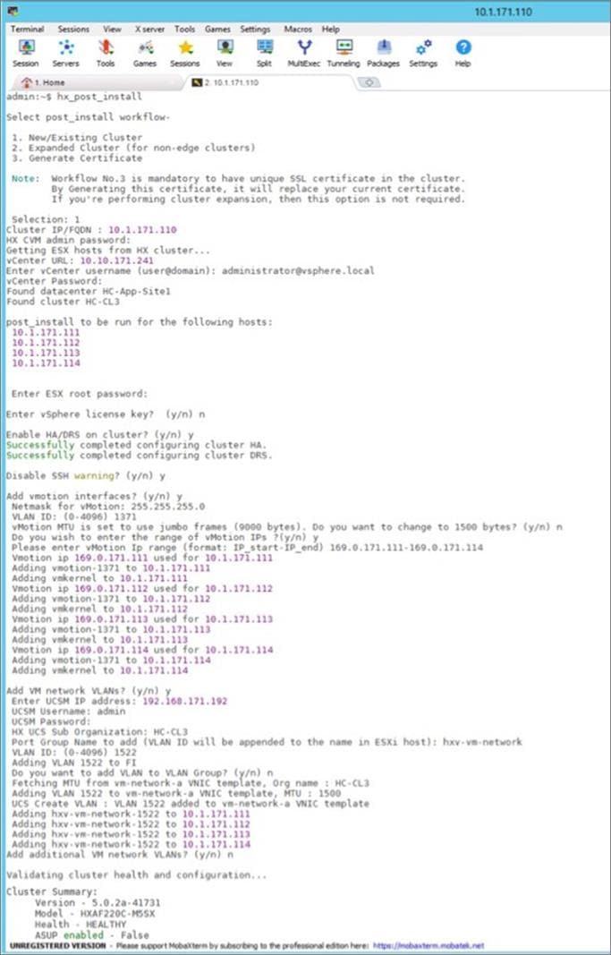
Procedure 9. Post-install tasks – Create datastores
To use the cluster, at least one datastore should be created before a Red Hat OCP cluster can be deployed on the Cisco HyperFlex VSI cluster. This task can be completed from Cisco Intersight.
Step 1. Use a web browser and navigate to Intersight.com and login using an admin account.
Step 2. Select Infrastructure Services from the drop-down list in the top left side of the Intersight GUI.
Step 3. Click HyperFlex Clusters in the left navigation bar
Step 4. Select the Application HyperFlex cluster (in this case, HC-CL3) from the list in the right window.
Step 5. Navigate to Operate > Datastores.
Step 6. Click Create Datastore from the right window.
Step 7. In the Create Datastore pop-up window, specify a Datastore Name and size (Capacity). For most applications, leave the Block Size at the default (8k). Only dedicated Virtual Desktop Infrastructure (VDI) environments should choose 4K Block Size.
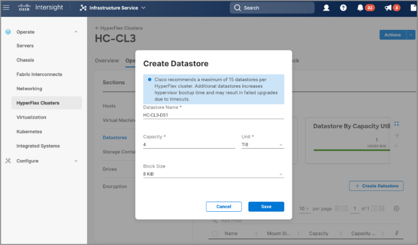
Step 8. Click Save.
The Cisco HyperFlex VSI is now ready for deploying the Red Hat OpenShift Container Platform as outlined in the next section.
Deploy Red Hat OpenShift Container Platform (On-Prem)
This section describes the deployment of the on-prem Kubernetes environment in this hybrid cloud solution. The Kubernetes environment deployed in the solution is Red Hat OpenShift Container Platform, deployed and managed from the cloud using Red Hat Hybrid Cloud Console. The cluster is deployed using the automated installer-provisioned infrastructure (IPI) method. The installer will prompt the user for minimal values to collect information that is environment and deployment specific. Red Hat does support customizations, but the IPI is the fastest way to deploy a production-ready OCP cluster. Other methods are outside the scope of this document
Prerequisites
The prerequisites for deploying Red Hat OCP are:
● Management infrastructure for deploying an installer workstation. The installer will need access to the Internet, Cisco HyperFlex VSI cluster, and VMware vCenter managing the vSphere cluster. Installer is supported on Linux and MacOS. Post-deployment, the installer will be used for SSH access and other management functions.
● Application Cisco HyperFlex VSI running VMware vSphere to host the Red Hat OCP cluster. The cluster should be fully licensed with vSphere HA/DRS enabled to ensure availability of the virtual machines that will serve as control and worker nodes in the Red Hat OCP cluster. Also, the cluster must be provisioned for at least one datastore for the VMs deployed by OCP.
● A valid Red Hat account to login to Red Hat Hybrid Cloud Console. Hybrid Cloud Console is used to centrally deploy and manage the on-prem and public cloud OCP clusters in the Enterprise.
● VLAN and IP subnet for the Red Hat OCP cluster. OCP cluster is deployed on a guest VM network on Cisco HyperFlex VSI. All nodes in an OCP cluster must be in the same VLAN. The VLAN must be provisioned in the ACI fabric, Cisco UCS Fabric Interconnects (port-channel uplinks), Cisco HyperFlex server (vNIC templates), and VMware ESXi hosts. A guest VM network deployed during Cisco HyperFlex VSI install will be used for the Red Hat OCP cluster. If the guest VLAN is provisioned using the Cisco HyperFlex installer or the post-install scripts, it will take care of configuring the VLAN across the different component, but the Cisco ACI fabric will still need to be provisioned.
● The ACI fabric will be the default gateway for the IP subnet allocated to the guest VM network and OCP cluster. The OCP clusters will use the ACI fabric for reachability to destinations outside the cluster based on established contracts. The ACI fabric will provide Internet access which will provide reachability Red Hat Hybrid Cloud Console, quay.io, Operator Hub and other services in the cloud. It will also enable the default Telemetry service running on the cluster to automatically register with the Hybrid Cloud Console. Telemetry service also provides remote health monitoring. The ACI fabric will also provide reachability to network services (DNS, DHCP, NTP), VMware vCenter, and Installer workstation hosted on a management cluster in the ACI fabric. Post-install, the installer will be used for SSH and debugging purposes and therefore will continue to need access to the OCP cluster.
● Installer requires two static IP addresses: [1] API address to access the cluster API and [2] Ingress address for cluster ingress traffic.
● DNS – The following DNS records for the two static IP addresses must be in place prior to install.
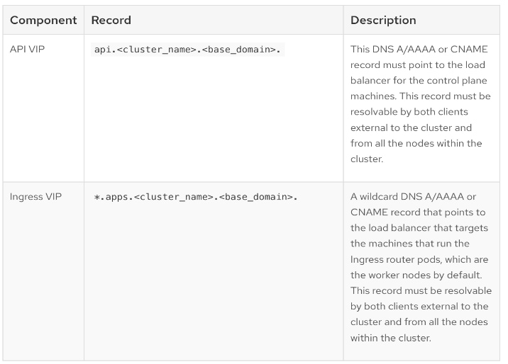
● DHCP is required to provide IP addresses to the cluster nodes (control/master, compute/worker). The DHCP server must be available and provisioned with a DHCP scope for the OCP subnet before the OCP cluster installation can begin.
● NTP – OCP cluster nodes should be configured for NTP, ideally during DHCP process.
● SSH Access – To debug the installation and for disaster recovery and other post-install activities, the SSH public keys must be provided to the OCP installer to authenticate the access. The key will be passed to the nodes through the initial configuration (ignition) files. The nodes will add the keys to the ~/.ssh/authorized_keys list for the core user to enable password-less authentication.
● VMware vCenter root CA certificates – To install the OCP cluster, the installer needs access to the VMware vCenter API. For this, the vCenter’s root CA certificates must be added to the system trust on the OCP installer workstation.
Setup Information
Table 10 lists the installation parameters for the on-prem deployment.
Table 10. Red Hat OCP - Installation Parameters for on-prem deployment
| Variable |
Variable Name |
Value |
Additional Info |
| DNS Server IP |
- |
10.10.171.240 |
|
| Base DNS Domain |
|
hc.com |
|
| Red Hat OCP Cluster Name |
- |
ocp11.hc.com |
|
| API VIP |
api.ocp11.hc.com |
10.171.11.252 |
|
| Ingress VIP |
*.apps.ocp11.hc.com |
10.171.11.253 |
|
| DHCP Server IP |
- |
10.10.171.240 |
|
| DHCP Scope |
- |
10.171.11.1 - 10.171.11.250 |
|
| NTP Server IP |
|
192.168.171.254 |
|
| Default Gateway IP |
- |
10.171.11.254 |
|
| VMware vCenter IP (& Login) |
vc1-1.hc.com |
10.10.171.241 |
Login Credentials |
| vCenter Datacenter Name |
- |
HC-App-Site1 |
For use by OCP Installer |
| vSphere Cluster Name |
- |
HC-CL3 |
For use by OCP Installer |
| vSphere Datastore Name |
- |
HC-CL3-DS1 |
For use by OCP Installer |
| vSphere Virtual Network |
hxv-vm-network-1521 |
VLAN 1521 |
For use by OCP Installer |
Deployment Steps
The section provides the procedures for deploying a Red Hat OCP cluster on a VMware vSphere HyperFlex cluster.
Procedure 1. Generate a key pair for SSH access to Red Hat OCP cluster
The commands you need are:
| Commands |
| ssh-keygen -t rsa -N '' -f <path>/<file_name> |
| eval "$(ssh-agent -s)" |
| ssh-add <path>/<file_name> |
Step 1. On the installer workstation running a Linux operating system, use the following command. You can generate the key using rsa or edcsa algorithm.
ssh-keygen -t rsa -N '' -f ~/.ssh/id_rsa
Step 1. Add the SSH private key identity to the SSH agent for your local user. If the ssh-agent process is not already running for your local user, start it as a background task:
eval "$(ssh-agent -s)"
Step 2. Add your SSH private key to the ssh-agent using the command:
ssh-add ~/.ssh/id_rsa
This key is provided as input to the installer. Installer will add it to the ignition files that are used to do the initial configuration of the OCP nodes. Once the OCP cluster is deployed, you will be able to access the cluster as user ‘core’ without the need for password.
Procedure 2. Download vCenter’s root CA Certificates to OCP installer’s system trust
Note: The installer needs API access to VMware vCenter to deploy the OCP cluster.
Step 1. Use a web browser to navigate to VMware vCenter. Login using an admin account.
Step 2. From the vCenter home page, select and click Download trusted root CA certificates from the bottom left side of the window. A download.zip file downloads.
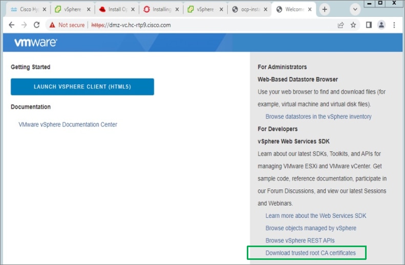
Step 3. Extract the vCenter root CA certificates from the downloaded file.
Step 4. Copy the certificates to the system trust for the operating system running on your workstation.
cp certs/lin/* /etc/pki/ca-trust/source/anchors
Step 5. Update the system trust on your workstation.
update-ca-trust extract
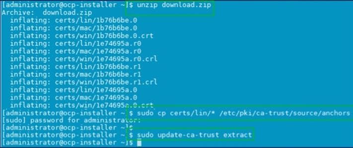
Procedure 3. Create DNS records for the Red Hat OCP cluster
Step 1. Create the API and Ingress DNS records required to deploy the OCP cluster. The records on a windows DNS server are shown below.
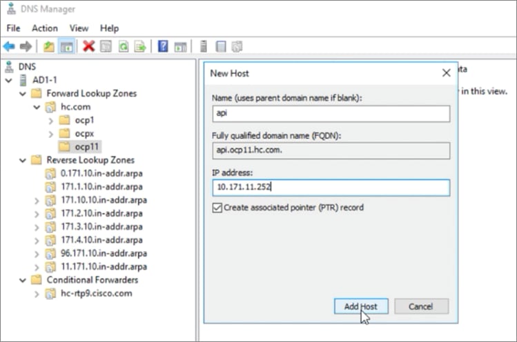
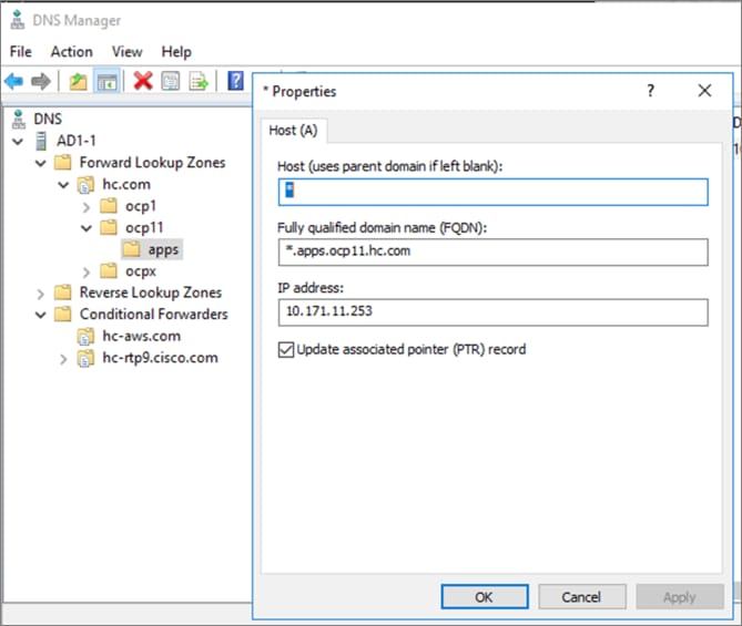
Procedure 4. Create a DHCP scope for the Red Hat OCP cluster
Step 1. Create a DHCP scope for the OCP cluster with scope options for Gateway, DNS server, base DNS domain and NTP. The DHCP configuration on a Windows DHCP server is shown below.
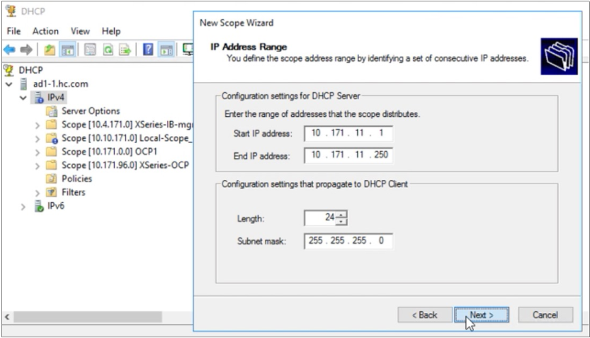
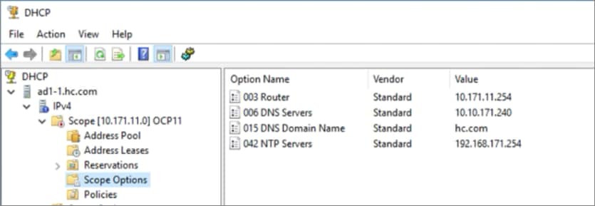
Procedure 5. Download the Red Hat OCP installer and other tools from Red Hat Hybrid Cloud Console
Step 1. Use a web browser and navigate to Red Hat Hybrid Cloud Console at console.redhat.com. Login to your Red hat account.
Step 2. From the left navigation pane, select and click OpenShift.
Step 3. Navigate to Clusters and click Create Cluster.
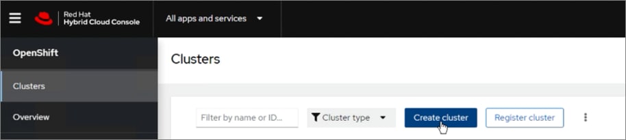
Step 4. Navigate to the Data Center tab.
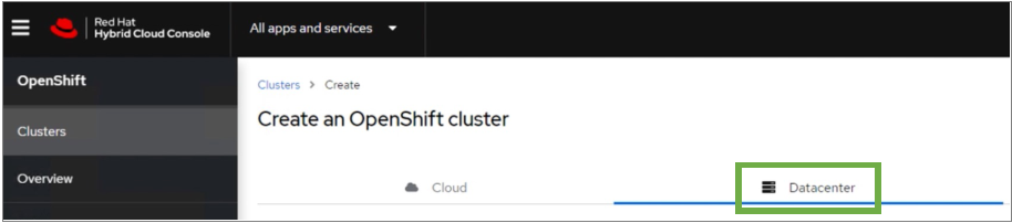
Step 5. Scroll down and click VMware vSphere for the infrastructure provider.
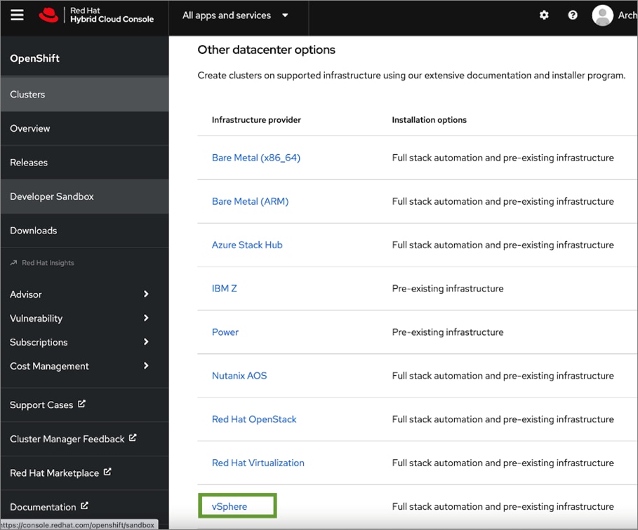
Step 6. Select the Automated, CLI-based Installer-Provisioned Infrastructure (IPI) method.
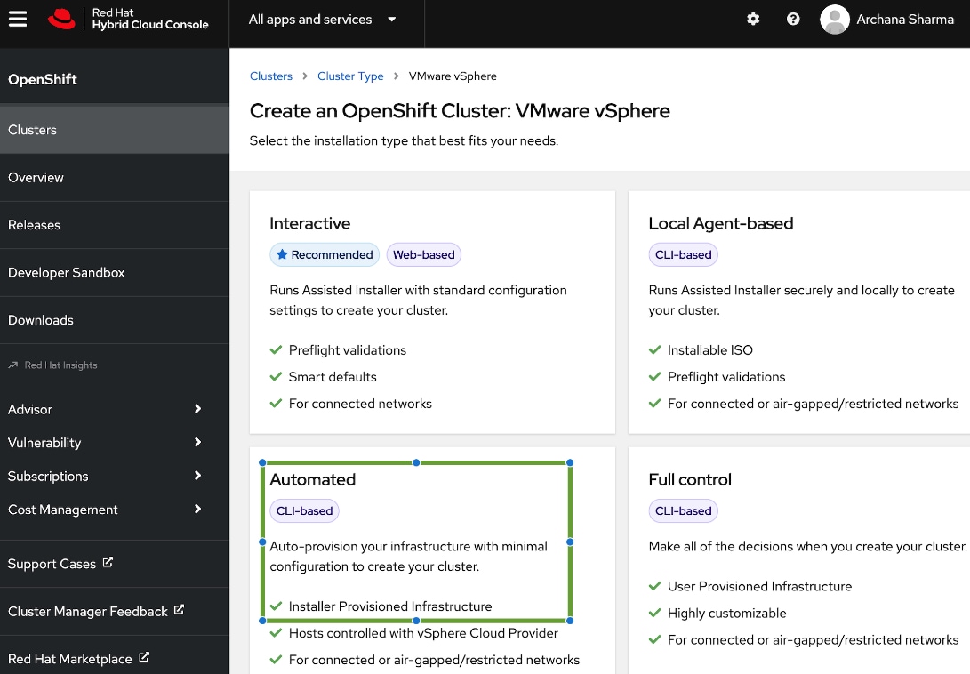
Step 7. From the Install OpenShift on vSphere with installer-provisioned infrastructure page, download the installation program for the operating system running on the installer workstation.
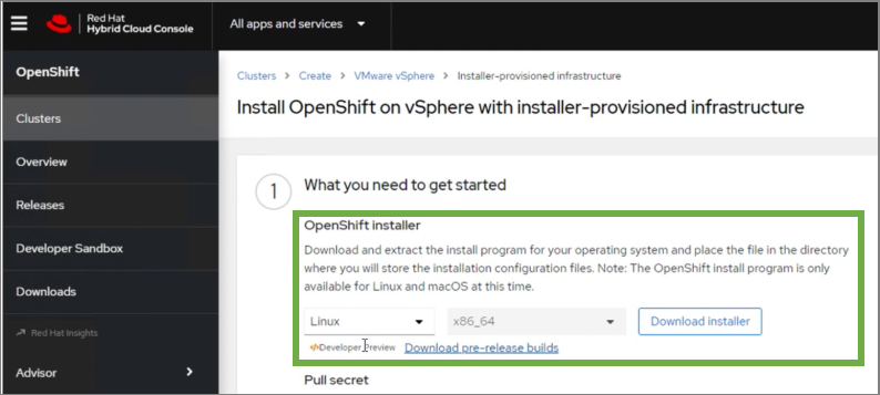
Step 8. On the installer workstation, create a directory for the cluster (in this case, ocp11) and move the installation package to this directory.
Step 9. Extract the installation package.

Step 10. Download the pull-secret and save it in a file in the same directory. This pull secret allows you to authenticate with the services that are provided by the included authorities, including Quay.io, which serves the container images for OpenShift Container Platform components.
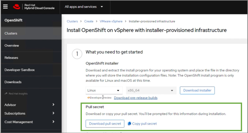
Step 11. Download the OpenShift CLI tools to the same directory.
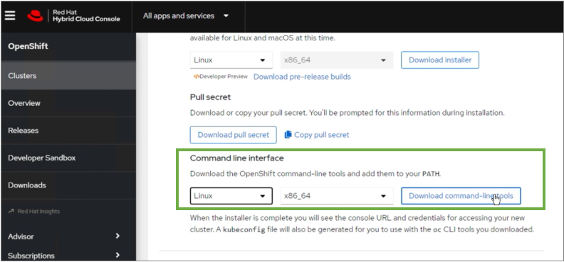
Procedure 6. Install Red Hat OpenShift Container Platform
Step 1. From step 2 in the Install OpenShift on vSphere with installer-provisioned infrastructure page, copy the command to run the installer that will create the cluster. You can specify additional options as shown below.
./openshift-install create cluster –dir=<installation_directory> --log-level=info
Step 2. Select the SSH public key to pass to the cluster nodes through the installation configuration (ignition) file.
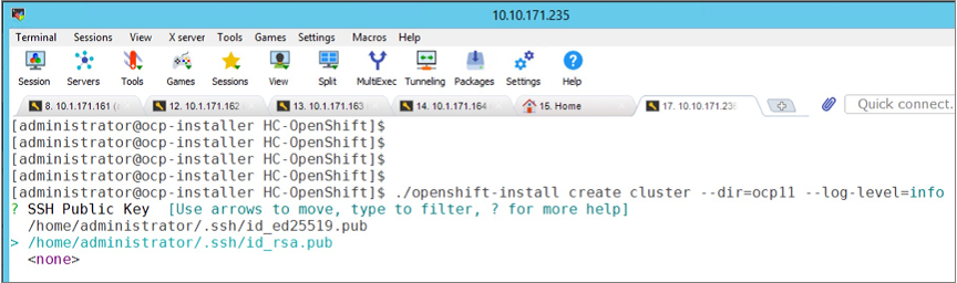
Step 3. Select infrastructure environment.
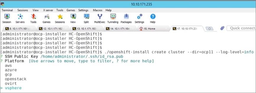
Step 4. Provide VMware vCenter information.
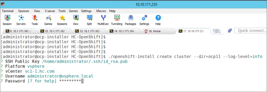
Step 5. Select a VMware vSphere cluster on which to deploy the OCP cluster.
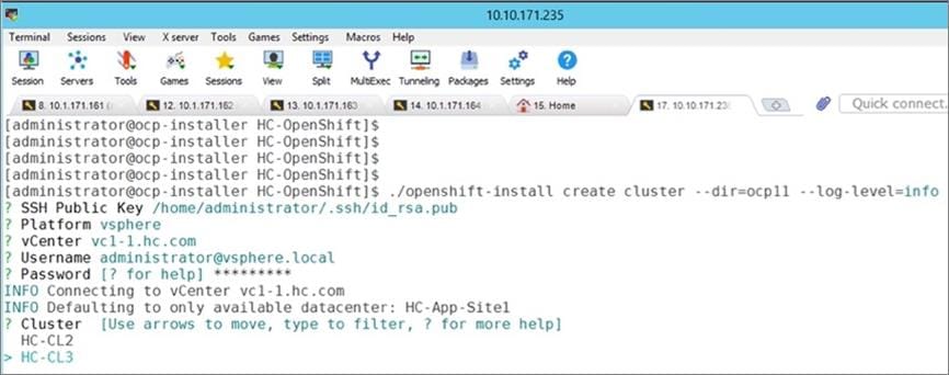
Step 6. Select a datastore to use.
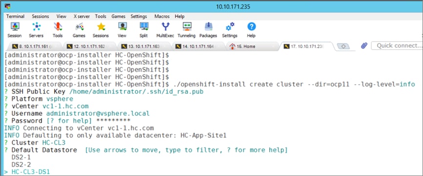
Step 7. Select a guest VM network for the OCP cluster.
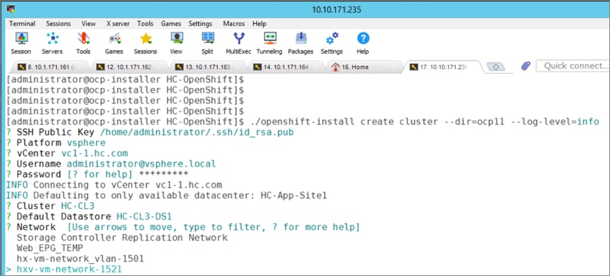
Step 8. Provide a Virtual IP (VIP) for API and Ingress.
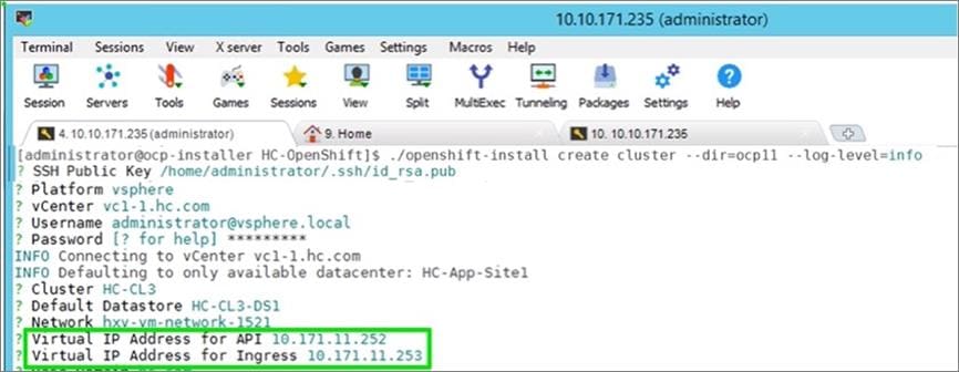
Step 9. Specify a base DNS domain and name for the OCP cluster.
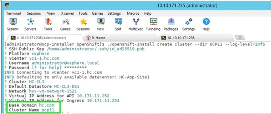
Step 10. Paste the pull secret copied from the Hybrid Cloud Console.
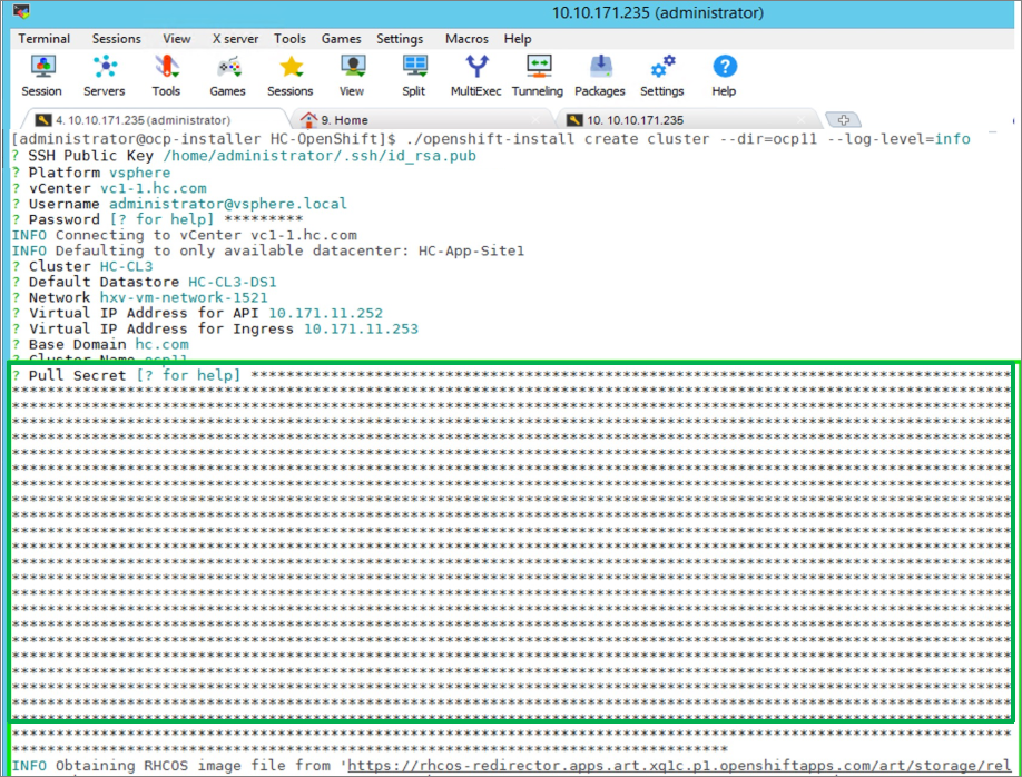
Note: Once the pull-secret is provided, the installer will start the OCP deployment. It will take around 45min. Once the OCP cluster is deployed, there are a few post-install tasks that must be completed.
Note: Do not remove the installer or the files created by the installer. These will be necessary to delete the cluster.
Procedure 7. Post-install task – Verify access to new cluster
Note: When the cluster installation finished, complete the following post-install tasks to verify that you can access the new cluster using command line tools and web console.
Step 1. To verify access via the command line, execute the following commands from the workstation:
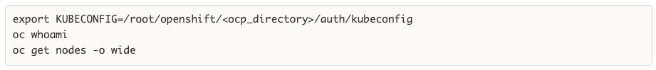
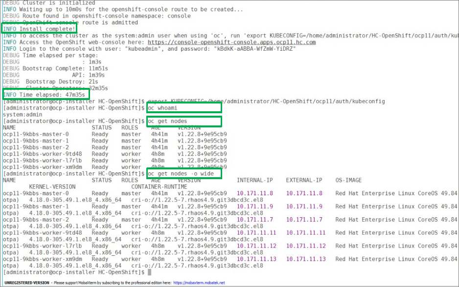
Step 2. To verify access via web console, open a web browser and navigate to the OpenShift Hybrid Cloud Console. Login using your Red Hat account. Navigate to Clusters and find the newly created OCP cluster. Select and click the cluster name.
Note: If your cluster has access to the Internet, the Telemetry service will automatically register with the Hybrid Cloud Console, and you will see it in the cluster list.
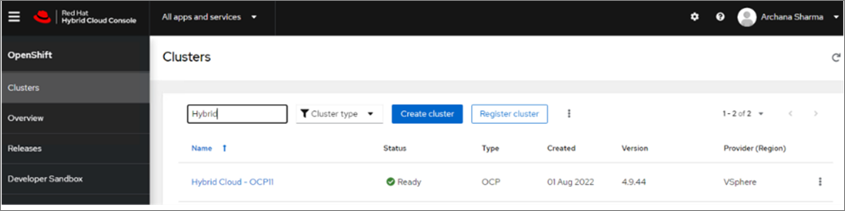
Step 3. Click Open console from the top-right corner and login to the cluster console as kubeadm user.
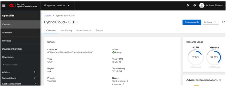
Step 4. Verify status and health of cluster from OCP cluster console.
Procedure 8. Post-install task – Provision anti-affinity rules on VMware vCenter
Note: Red Hat recommends VMware anti-affinity rules to improve the availability of OpenShift Container Platform during maintenance or hardware issues.
This procedure will enable VMware anti-affinity rules to distribute OCP cluster nodes across all HyperFlex ESXi hosts in the cluster.
Step 1. Open a web browser and navigate to VMware vCenter managing the Application HyperFlex VSI cluster. Login as administrator.
Step 2. From Hosts and Clusters view, navigate to the Application VMware vSphere cluster. Identify the OCP cluster nodes.
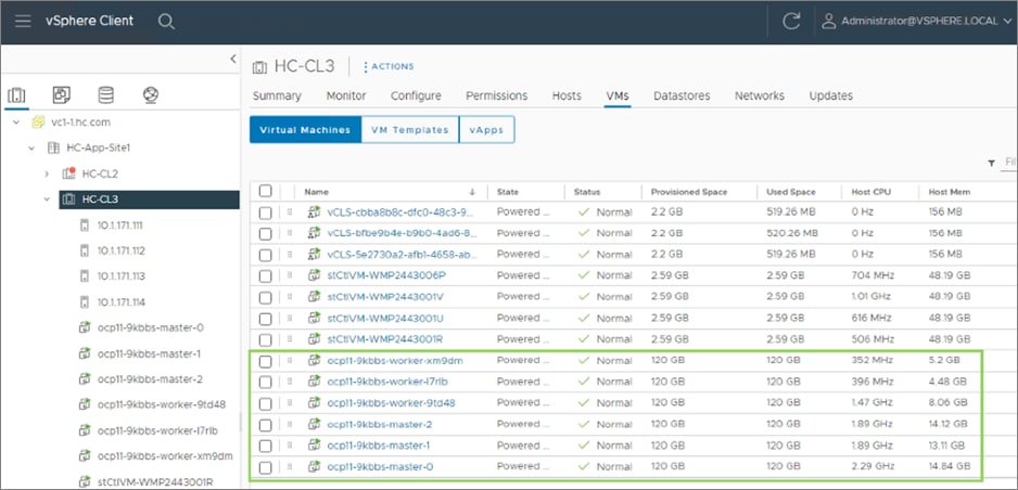
Step 3. Click the Configure tab and select VM/Host Rules from the left navigation pane. Click Add in the right window.
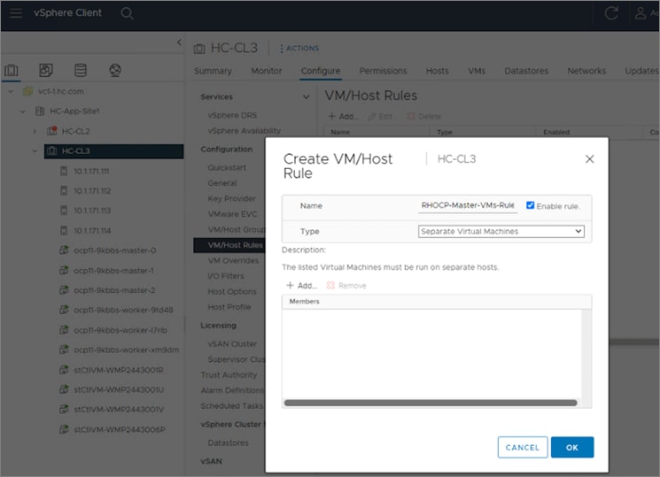
Step 4. In the Create VM/Host Rule pop-up window, specify a name for control/master nodes rule. Set the Type as Separate Virtual Machines, then click Add to add control nodes that the rule applies to.
Step 5. In the Add Virtual Machine pop-up window, select the three OCP Control VMs from the list, then click OK.
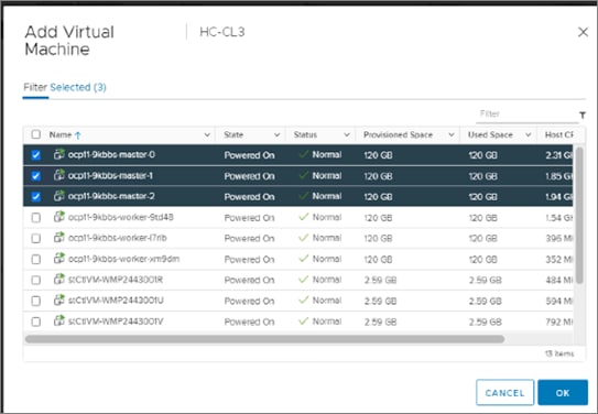
Step 6. Click OK to create the rule for OCP Control/Master VMs.
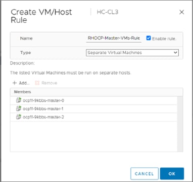
Step 7. Repeat steps 3-6 to distribute the worker VMs across all available Cisco HyperFlex nodes.
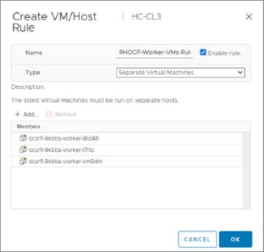
Deploy Red Hat OpenShift Container Platform (Public Cloud)
With the deployment of the on-prem cloud-native environment complete, the first deployment step in the public cloud is to deploy Red Hat OCP since there is no underlying infrastructure that needs to be setup in public cloud. The OCP cluster is deployed and managed from the cloud using the same Red hat Hybrid Cloud Console that was used on-prem. The cluster will also be deployed using the same IPI installation method as on-prem. This will provide Enterprises developers and operators with a consistent environment from on-prem to public cloud.
Note: Red Hat supports multiple customization options, both for deployment and post-deployment. Custom deployments are outside the scope of this document.
Prerequisites
The prerequisites for the Red Hat OCP deployment in AWS are:
● A valid AWS account to deploy resources in AWS.
● AWS Account – IAM User: Create or use an IAM user with administrative privileges (not the root user) to deploy the OCP cluster. The administrative privileges can be removed post-installation.
● AWS Account – Service Limits: You may need to increase the default service limits on the account to deploy an OCP cluster. For example, in the AWS us-east-1 region with six availability zones, the default installation requires 6 Elastic IPs when the default is 5, so you will need to increase this limit. Alternatively, you can modify the default installation configuration file or pick a region with fewer availability zones.
● Installer workstation. The installer will need access to the Internet and to the VPC environment in the AWS account where the cluster is being deployed. Post-deployment, the installer will be used for SSH access and other management functions. The installer will need to be reachable from the Enterprise. The installer is an AWS EC2 instance.
● A valid Red Hat account to login to Red Hat Hybrid Cloud Console. Hybrid Cloud Console is used to centrally deploy and manage the on-prem and public cloud OCP clusters in the Enterprise.
● Internet Access for the Red Hat OCP cluster for accessing the Hybrid Cloud Console to manage the cluster, including subscriptions and telemetry. A newly deployed will also automatically register with Hybrid Cloud Console if it has Internet access and telemetry service enabled (default). OCP cluster also needs access to Quay.io to access packages for initial deployment and for upgrades.
● DNS – A dedicated base DNS domain or public hosted zone must be defined in Route 53 for deploying Red Hat OCP in AWS. Route 53 service in AWS provides DNS resolution for the OCP cluster and for external connections to the cluster. The zone must be authoritative for the domain.
● SSH Access – To debug the installation and for disaster recovery and other post-install activities, the SSH public keys must be provided to the OCP installer to authenticate the access. The key will be passed to the nodes through the initial configuration (ignition) files. The nodes will add the keys to the ~/.ssh/authorized_keys list for the core user to enable password-less authentication.
Setup Information
Table 11 lists the installation parameters for AWS.
Table 11. Red Hat OCP - Installation Parameters for AWS
| Variable |
Variable Name |
Value |
Additional Info |
| Base DNS Domain |
Public Hosted Zone |
hc-aws.com |
|
| AWS Region |
- |
us-east-1 |
Region to deploy OCP cluster in |
| Red Hat OCP Cluster Name |
- |
ocp11.hc-aws.com |
|
Deployment Steps
This section describes the procedures for the deployment of a Red Hat OCP environment in AWS.
Procedure 1. Create an IAM user with administrator privileges
Note: Every AWS account has a root user account with all privileges, but it is a best-practice not to use this account other than for creating additional users or billing. For this reason, create a second IAM administrative user as outlined below.
Step 1. Use a web browser to navigate to console.aws.amazon.com. Login to your AWS account. Click IAM.
Step 2. From the left navigation pane, select Users.
Step 3. From the right-window pane, click Add Users. Specify a username (for example, ocp-admin). Select AWS Credential type as Access key – Programmatic access for OCP.
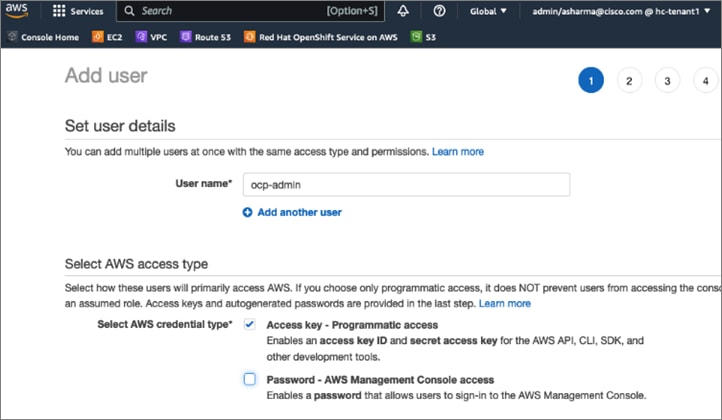
Step 4. Scroll down and click Next:Permissions. Select Attach existing policies directly and select the checkbox next to policy named: ‘AdministratorAccess.’
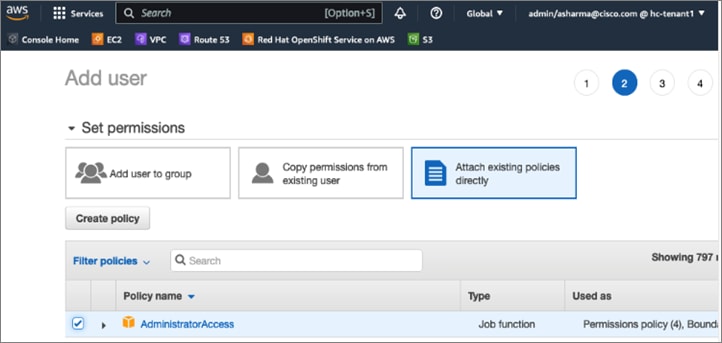
Step 5. Scroll down and click Next:Tags. Add optional tags. Click Next:Review and click Create user.
Step 6. Save the Access key id and Secret access key for use in a secure place.
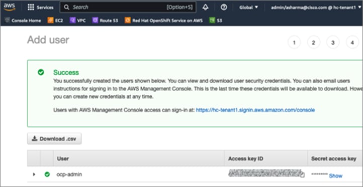
Procedure 2. Increase AWS Account Service Limits
The default limits for AWS services (for example, Instance limits, Elastic IPs) may need to be increased depending on where you're deploying the cluster. For example, in AWS region us-east-1, the Elastic IP limit will need to be increased from 5 to 6 for the default OCP installation to use the six availability zones in us-east-1.
You can follow a similar process to increase other service limits.
Step 1. Use a web browser to navigate to console.aws.amazon.com. Login using your AWS account.
Step 2. Right-click your account name in the top right-hand corner of the window and select Service Quotas from the drop-down list.
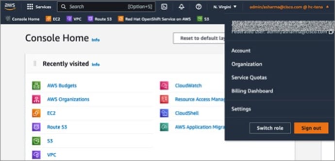
Step 3. Click Service Quotas and from the Dashboard in the left navigation pane, select the service category (for example, Amazon EC2).
Step 4. Click the specific service item (for example, EC2-VPC Elastic IPs)
Step 5. Click Request Quota Increase to provide the necessary information to generate the request.
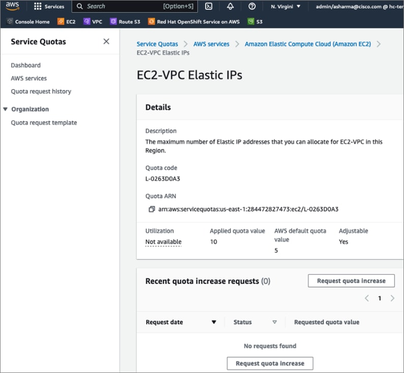
Note: You can also request service limits for Elastic IPs by navigating to EC2 > Limits from the console home.
Procedure 3. Provision a base DNS domain in AWS Route 53
Red Hat OCP in AWS requires a dedicated public hosted zone defined in Route 53 for use by the cluster and for name resolution when accessing the cluster from external locations.
Step 1. Use a web browser to navigate to console.aws.amazon.com. Login using your AWS account. Click Route 53.
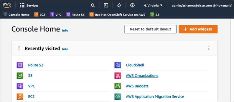
Step 2. From the navigation pane, select Hosted Zones > Create hosted zone.
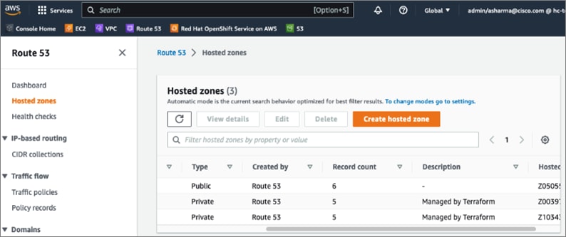
Step 3. In the Create Hosted Zone window, enter a domain name (for example, hc-aws.com) that you want to use. For Type, use Public Hosted Zone. OCP does use a private zone for the cluster, but it is deployed and configured by the installer.
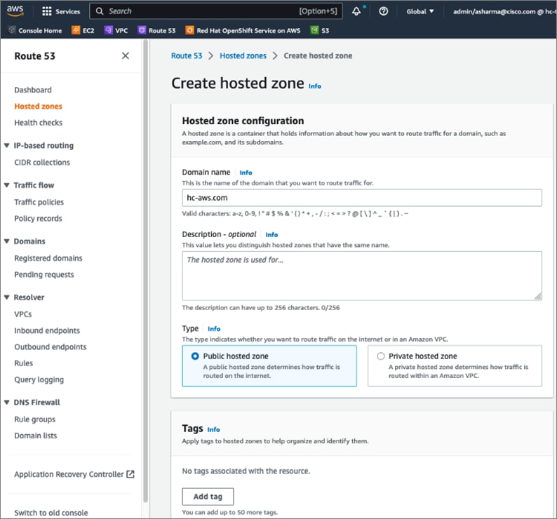
Step 4. Scroll down to the bottom and click Create hosted zone. A new hosted zone will now be created to enable traffic to be routed to your domain.
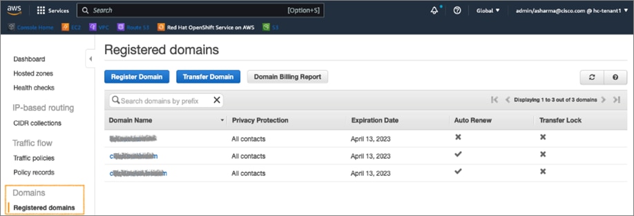
Step 5. From the navigation pane, under Domains, select Registered domains and click Register Domain.
Step 6. In the Domain Search window, choose a domain name (for example, hc-aws) and extension (.com) from the drop-down list. Click Check to verify it is available.
Step 7. If it is available, you can click Add to cart and click Continue to proceed further.
Step 8. In the Contact Details window, provide contact information for your domain. Click Continue.
Step 9. In the Verify and Purchase window, verify the information provided, agree to the terms and conditions, and click Complete Order to register the domain. You will receive notification from AWS when the domain is available – it may take a few minutes to complete.
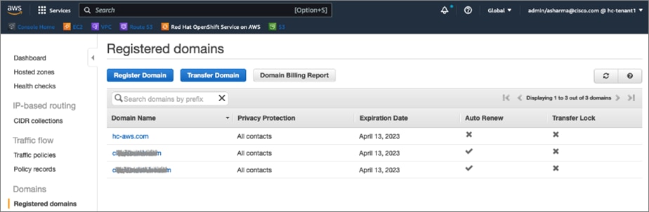
Step 10. You can view details of your domain by clicking on the newly created domain from the list of Registered domains.
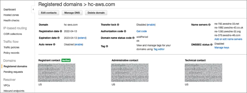
Step 11. Once the cluster is deployed, you can go back to Route 53 > Hosted zones to see the Red Hat OCP installer provisioned records in the public and private zones, and routing info for the DNS records.
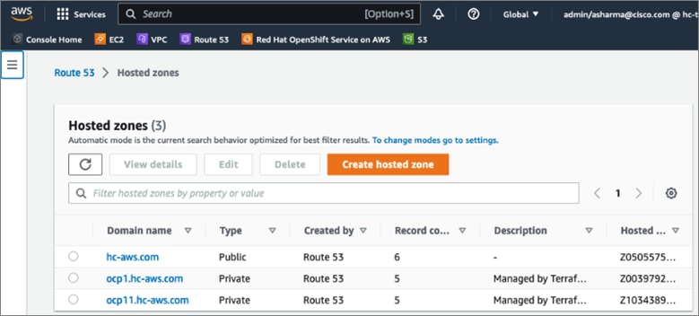
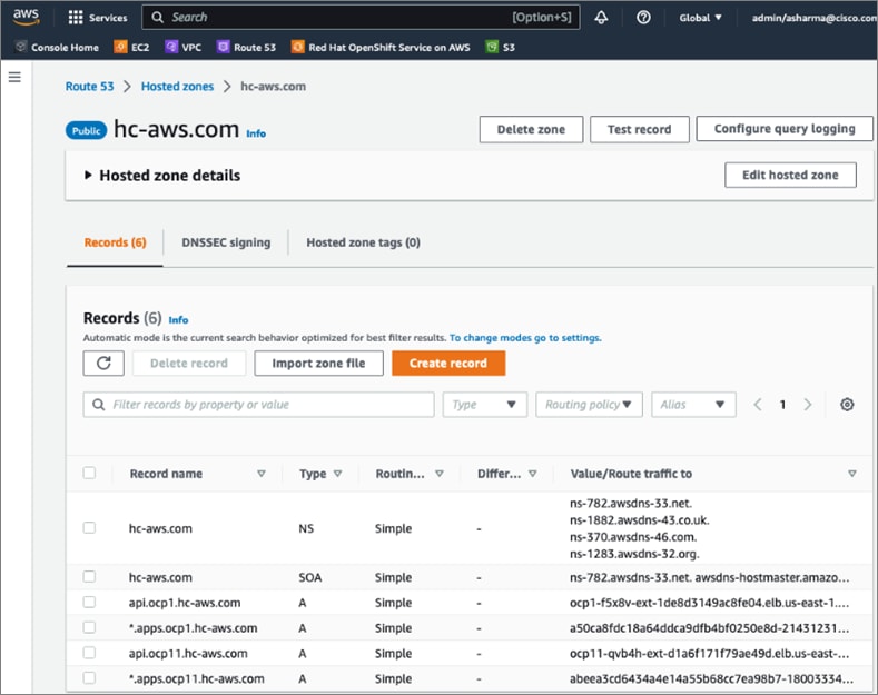
Procedure 4. Generate a key pair for SSH access to Red Hat OCP cluster
The commands you will need for this are:
| Commands |
| ssh-keygen -t rsa -N '' -f <path>/<file_name> |
| eval "$(ssh-agent -s)" |
| ssh-add <path>/<file_name> |
Step 1. On the installer workstation running a Linux operating system, use the following command. You can generate the key using rsa or edcsa algorithm.
ssh-keygen -t rsa -N '' -f ~/.ssh/id_rsa
Step 2. Add the SSH private key identity to the SSH agent for your local user. If the ssh-agent process is not already running for your local user, start it as a background task:
eval "$(ssh-agent -s)"
Step 3. Add your SSH private key to the ssh-agent using the command:
ssh-add ~/.ssh/id_rsa
The above key is provided as input to the installer. Installer will add it to the ignition files that are used to do the initial configuration of the OCP nodes. When the OCP cluster is deployed, you will be able to SSH into the cluster as user ‘core’ without the need for a password.
Procedure 5. Download the Red Hat OCP installer and other tools from Red Hat Hybrid Cloud Console
Step 1. Use a web browser to navigate to Red Hat Hybrid Cloud Console at console.redhat.com. Login to your Red Hat account.
Step 2. From the left navigation pane, select and click OpenShift.
Step 3. Navigate to Clusters and click Create Cluster.
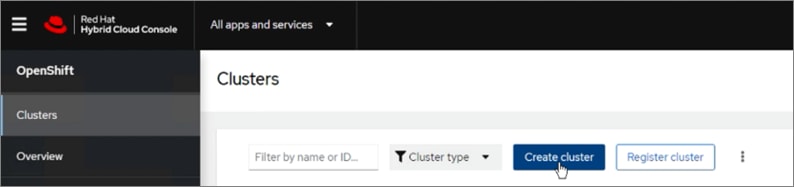
Step 4. Navigate to the Cloud tab
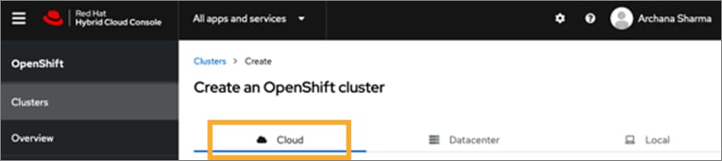
Step 5. Scroll down and click AWS for the infrastructure provider.
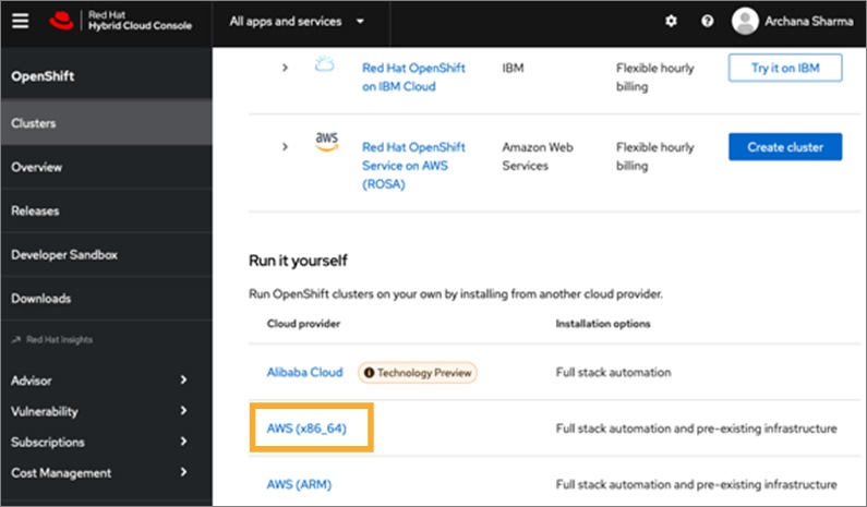
Step 6. Select the Installer-Provisioned Infrastructure (IPI) method.
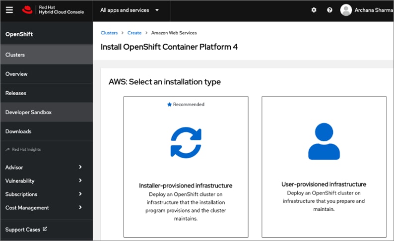
Step 7. From the AWS infrastructure page, download the installation program for the operating system running on the EC2 installer workstation.
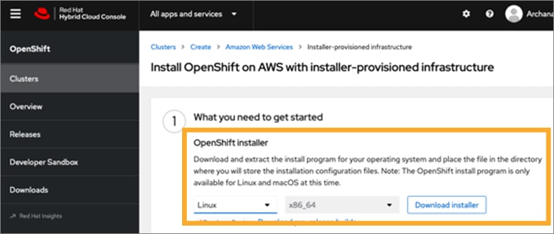
Step 8. On the installer workstation, create a directory for the cluster (in this case, ocp11) and move the installation package to this directory.
Step 9. Extract the installation package.

Step 10. Download the pull-secret and save it in a file in the same directory. This pull secret allows you to authenticate with the services that are provided by the included authorities, including Quay.io, which serves the container images for OpenShift Container Platform components. Also copy the pull secret.
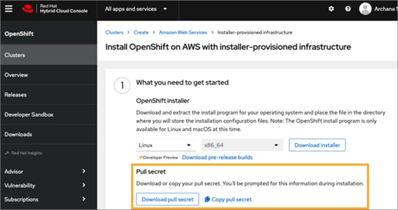
Step 11. Download the OpenShift CLI tools to the same directory.
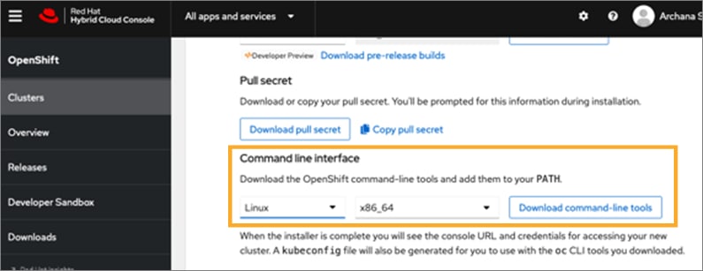
Procedure 6. Install Red Hat OpenShift Container Platform in AWS
Step 1. Execute the following command to run the installer:

Step 2. From the installer workstation, run the following command to start the installation process

Step 3. Select the SSH public key to pass to the cluster nodes through the installation configuration (ignition) file.
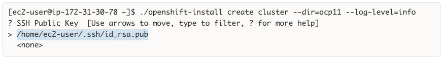
Step 4. Select infrastructure environment.
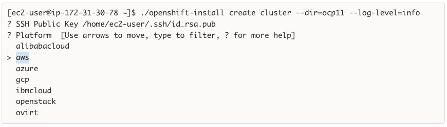
Step 5. Select the AWS region to deploy the cluster in.
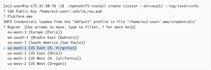
Step 6. Select the base domain or the Route 53 public hosted zone that was created for this cluster.
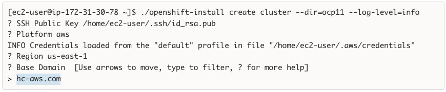
Step 7. Select a name for the OCP cluster.
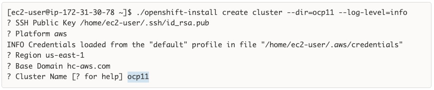
Step 8. Paste the pull secret copied/downloaded from the Hybrid Cloud Console.
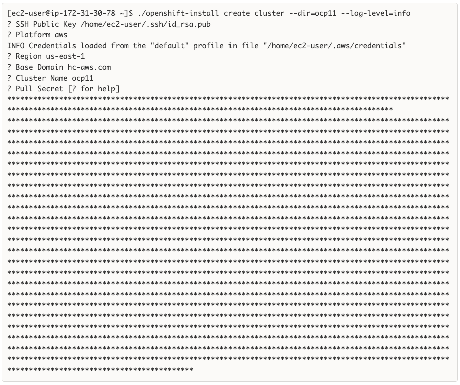
Step 9. Once the pull-secret is provided, the installer will start the OCP deployment. It will take around 45min. Once the OCP cluster is deployed, there are a few post-install tasks that must be completed.
Note: Do not remove the installer or the files created by the installer. These will be necessary to delete the cluster.
Procedure 7. Post-install task – Verify access to new cluster
When the cluster installation finished, complete the following post-install tasks to verify that you can access the new cluster using the command line tools and the web console.
Step 1. To verify access via the command line, execute the following commands from the workstation:
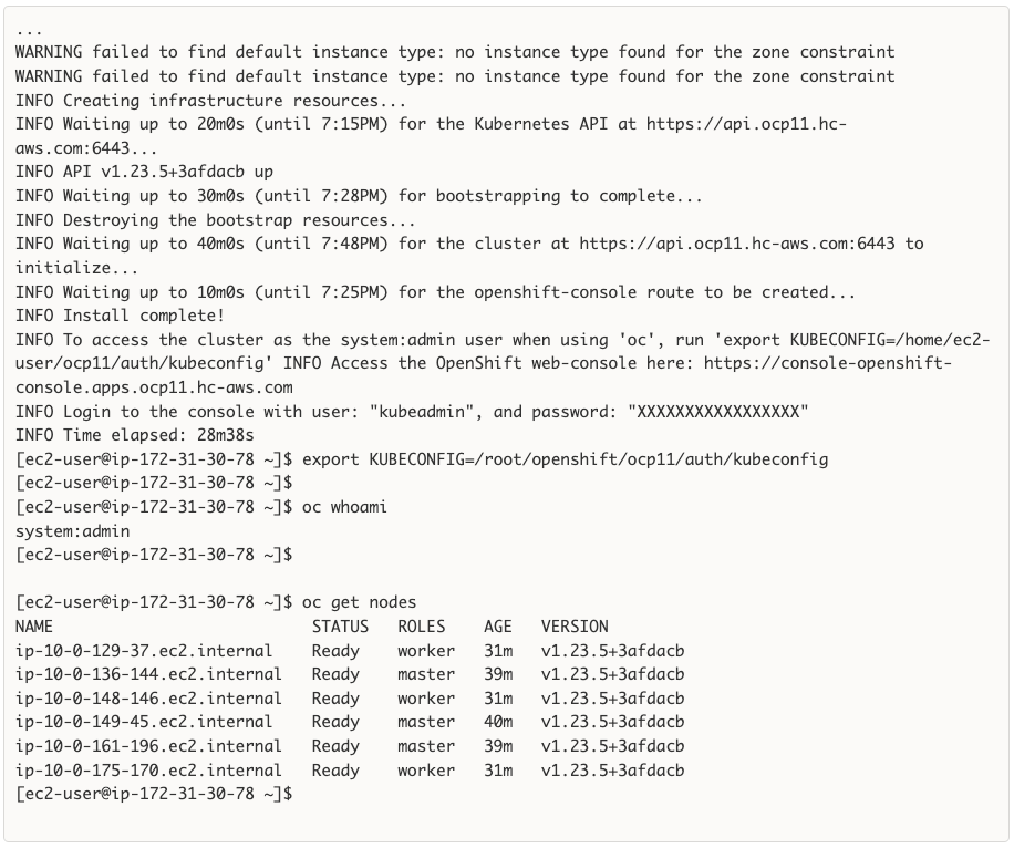
Step 2. To verify access via web console, open a web browser and navigate to the OpenShift Hybrid Cloud Console. Login to your Red Hat account. Navigate to OpenShift > Clusters and find the newly created OCP cluster. Select and click the cluster name.
Note: If your cluster has access to the Internet, the Telemetry service will automatically register with the Hybrid Cloud Console, and you will see it in the cluster list.
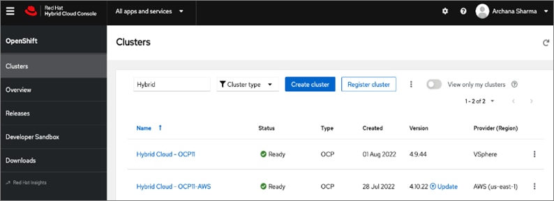
Step 3. Click Open console from the top-right corner and login to the cluster console as kubeadm user.
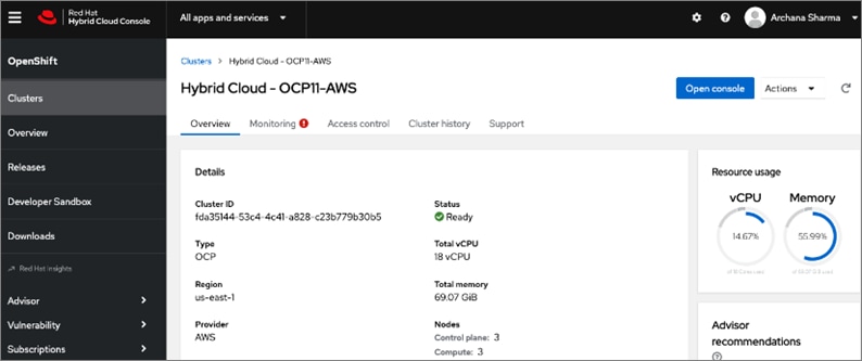
Step 4. Verify status and health of cluster from OCP cluster console.
Procedure 8. Post-install task: Set up a Bastion Node for SSH Access
The OCP cluster nodes on EC2 instances in AWS are deployed in a private subnet. To access these nodes using SSH would require a bastion node or jump box in the same VPC as the cluster nodes but with a public IP so that you can access it from outside AWS.
This procedure enables you to deploy an EC2 instance as a bastion node for SSH access.
Step 1. Use a web browser to navigate to console.aws.amazon.com. Login to your AWS account.
Step 2. Navigate to EC2 > Instances.
Step 3. Click Launch Instances. Provide a Name.
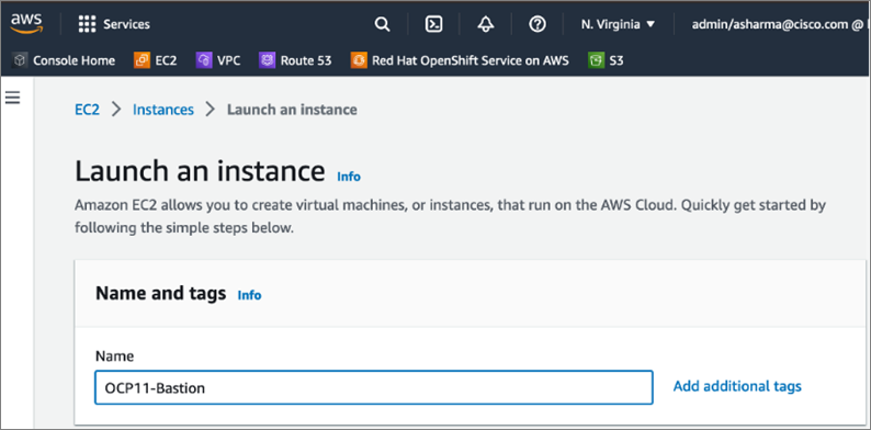
Step 4. Scroll down and select an OS image from the options.
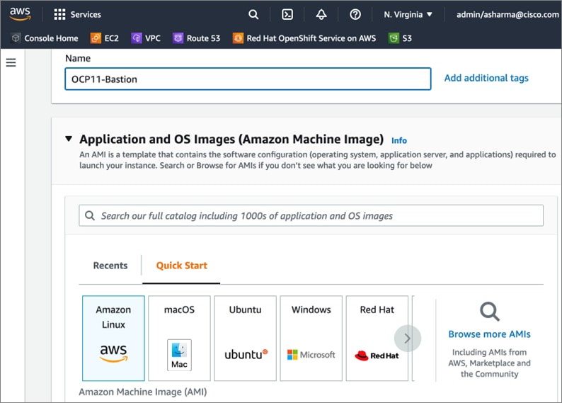
Step 5. Scroll down and select a Key pair from the drop-down list or create a new pair.
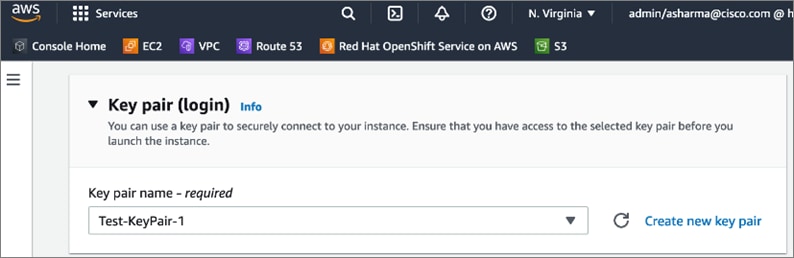
Step 6. Scroll down to Network settings. Click Edit.
Step 7. For the VPC, select the OCP cluster VPC from the drop-down list.
Step 8. For the Subnet, select a Public subnet in the deployed by the OCP installer.
Step 9. For the Auto-Assign public IP, select Enable from the drop-down list.
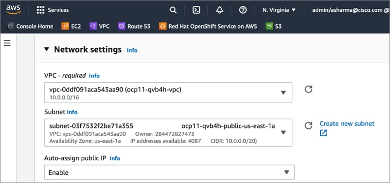
Step 10. Scroll down to Firewall (security groups). Specify a Security group name for the new security group. Update the description as needed.
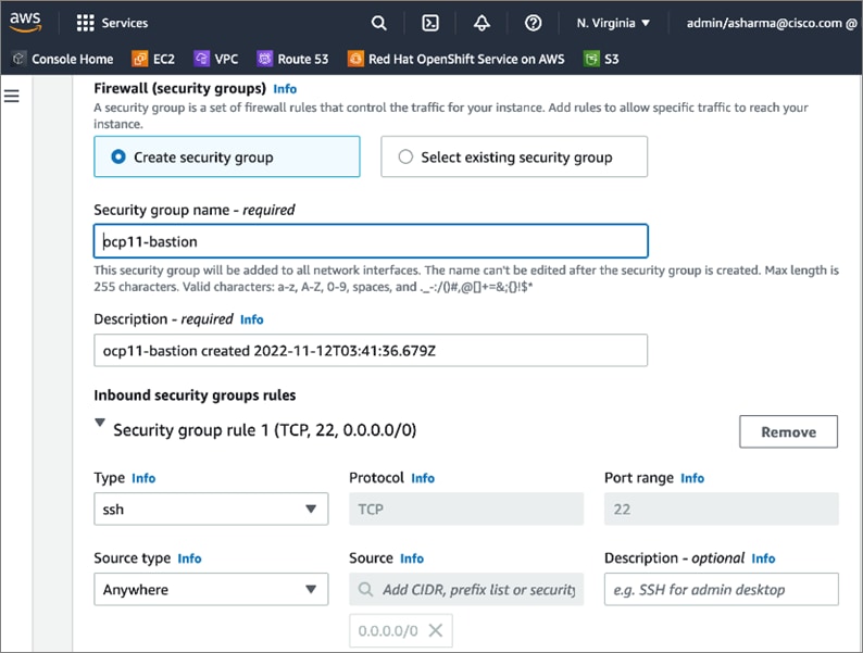
Step 11. Scroll down and click Launch Instance.
Step 12. If an inbound rule for SSH does not already exist on the master and worker nodes, add a new inbound rule. The rule would allow SSH access from the new bastion security group. From the AWS console, navigate to EC2 > Instances and select one of the master node instances in the cluster. In the bottom window, navigate to Security groups and click the name (terraform-xxx) to take you to the security group for master nodes.
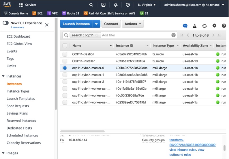
Step 13. Click Actions and select Edit inbound rules from the drop-down list.
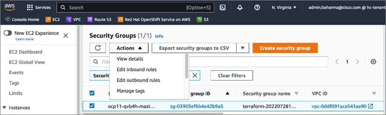
Step 14. In the Edit inbound rules window, scroll down to the bottom and click Add Rule. In the last row, edit the new rule Type and select SSH from the drop-down list. For the Source, select the security group rule created earlier for the bastion node.
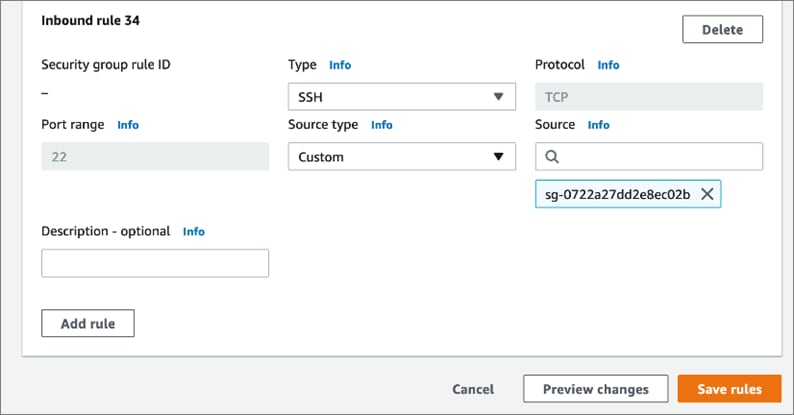
Step 15. Click Save Rules.
Step 16. Repeat steps 12-15 for a worker node.
Step 17. The next few steps are to copy the SSH private key to the bastion node. This is the key pair whose public key was provided to the OCP installer to install the cluster. The private key is in the OCP installer (~/.ssh/id_rsa – not id_rsa.pub). You can use SCP to copy the file the OCP installer to the public IP of the bastion node as outlined below.
Note: Secure the private keys. If your private key is compromised, your OCP cluster and applications running on it could be at risk.
Step 18. From the local workstation used to SSH into OCP installer, copy the PEM file for SSH access to Bastion node, to the OCP Installer.

Step 19. SSH into the OCP Installer.

Step 20. From OCP Installer, copy private key (not id_rsa.pub) to OCP Bastion workstation.

Step 21. From the OCP installer, note the private DNS hostname of the OCP cluster node. You cannot run the OCP cluster CLI tools from the Bastion node as you haven’t installed them on the Bastion node.
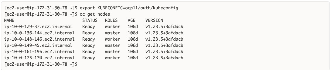
Step 22. SSH into Bastion workstation directly from OCP Installer.

Step 23. SSH from Bastion workstation to OCP cluster node.

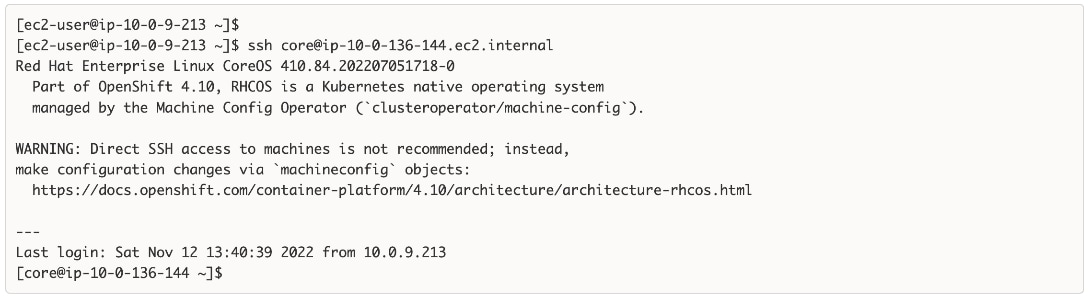
Now you have SSH access to Red Hat OCP cluster in an Amazon VPC.
Procedure 9. (Optional) Remove the Administrator Access policy for the IAM account
The IAM account that was created earlier with Administrator Access policy is only required for installation and can be disabled and changed to Read Only or some other lower-level access policy.
Enable Secure Hybrid Cloud Connectivity
This section describes the deployment of secure hybrid cloud connectivity between an on-prem data center and public cloud. The solution uses IPsec VPN connections established between CSR1000v routers in the Enterprise and Transit Gateway routers in AWS.
Prerequisites
The prerequisites for deploying IPsec VPN between on-prem and public cloud are:
● Enterprise Gateways (in this case, CSR1000v) deployed using stable, recommended version of software with configuration in place for out-of-band management, connectivity to the Enterprise data center network (Cisco ACI in this case), connectivity to the Internet.
● Public IPs allocated for the Enterprise gateways
● Enterprise Firewall provisioned to allows IPsec protocols and traffic to the public IP of the Enterprise gateways from AWS Transit Gateways (you will get this information when TGW is deployed).
● Determine the routing protocol to use (static or dynamic - BGP)
● If using dynamic, then Autonomous System Number (ASN) for BGP on Enterprise side. You can also specify the AWS side or use the default that AWS uses.
● Identify a summary route or routes that should be advertise to AWS VPCs. For static routing, static routes will be added to TGW.
● Identify VPC ID(s) if attaching multiple VPCs to TGW – an attachment per VPC (and VPN) will need to be created for the Transit Gateway.
Setup Information
Table 12 lists the configuration parameters for the site-to-site IPsec VPN.
Table 12. Site-to-Site IPsec VPN - Configuration Parameters
| Variable |
Variable Name |
Value |
Additional Info |
| Transit Gateway Name |
Name Tag |
HC-TGW-0 |
|
| AWS ASN (Optional) |
- |
65512 |
You can also AWS default. |
| Transit Gateway CIDR Block (Optional) |
CIDR |
99.0.0.0/24 |
You can also AWS default. Specifying for ease of troubleshooting. |
| VPC Attachment Name (s) |
- |
TGW-VPC-Attachment |
|
| Name for CSR1kv-1 |
Name Tag |
customer-gateway-1 |
|
| ASN for CSR1kv-1 |
|
65251 |
Not used but specifying it for future use. |
| Public IP for CSR1kv-1 |
|
<specify> |
|
| Name for CSR1kv-2 |
Name Tag |
customer-gateway-2 |
|
| ASN for CSR1kv-2 |
|
65251 |
Not used but specifying it for future use. |
| Public IP for CSR1kv-2 |
|
<specify> |
|
| Site-to-Site VPN Name (s) |
Name Tag |
VPN-181 VPN-182 |
|
| VPN Attachment Name (s) |
- |
TGW-VPN-Attachment1 TGW-VPN-Attachment2 |
|
Deployment Steps
The procedures in this section will enable hybrid cloud connectivity between on-prem and public cloud.
Procedure 1. Deploy Transit Gateway (TGW) in AWS
Step 1. Use a web browser to navigate to console.aws.amazon.com. Login to your AWS account.
Step 2. Navigate to VPC > Transit gateways from the left navigation pane.
Step 3. Click Create Transit Gateway.
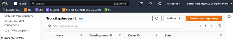
Step 4. In the Create Transit Gateway window, specify a Name tag, Description, ASN and accept the remaining defaults.
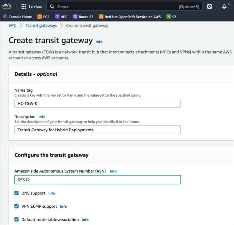
Step 5. Provide a CIDR subnet for TGW to use.
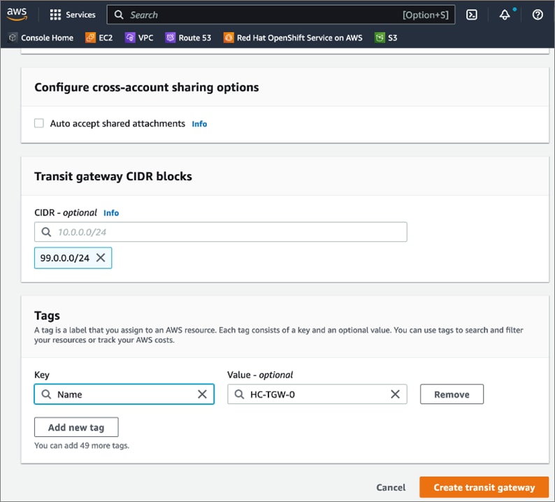
Step 6. Click Create transit gateway.
Procedure 2. Create TGW attachment to Red Hat OCP cluster in AWS VPC
Step 1. Use a web browser to navigate to console.aws.amazon.com. Login to your AWS account.
Step 2. Navigate to VPC > Transit gateways attachments from the left navigation pane.
Step 3. Click Create transit gateway attachment.

Step 4. In the Create transit gateway attachment window, specify a Name tag. For the Transit gateway id, select the newly created TGW from the drop-down list. For the Attachment type, select VPC.
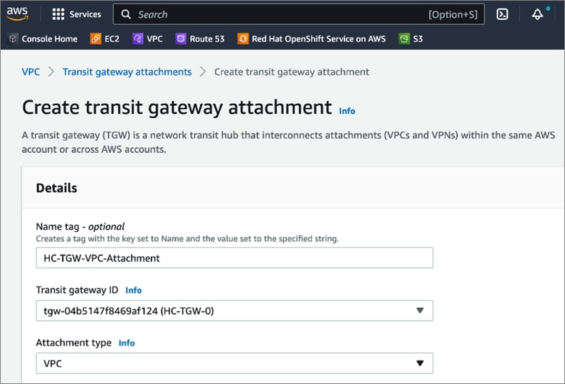
Step 5. In the VPC Attachment section, for the VPC ID, select the OCP cluster VPC from the drop-down list. For Subnet IDs, select the subnets to create an attachment for in each availability zone.
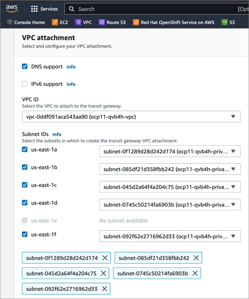
Step 6. Scroll down to the bottom and click Create transit gateway attachment.
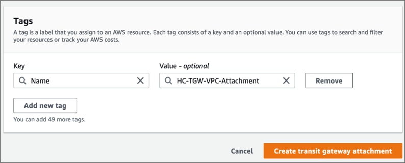
Step 7. Verify it is successfully created.
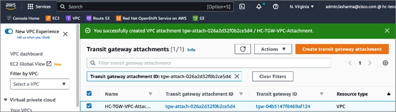
Procedure 3. Create Customer Gateways in AWS VPC
Customer gateways in AWS represent the on-prem gateways on the other end of the site-to-site VPN.
Step 1. Use a web browser to navigate to console.aws.amazon.com. Login to your AWS account.
Step 2. Navigate to VPC > Customer gateways from the left navigation pane.
Step 3. Click Create transit gateway attachment.
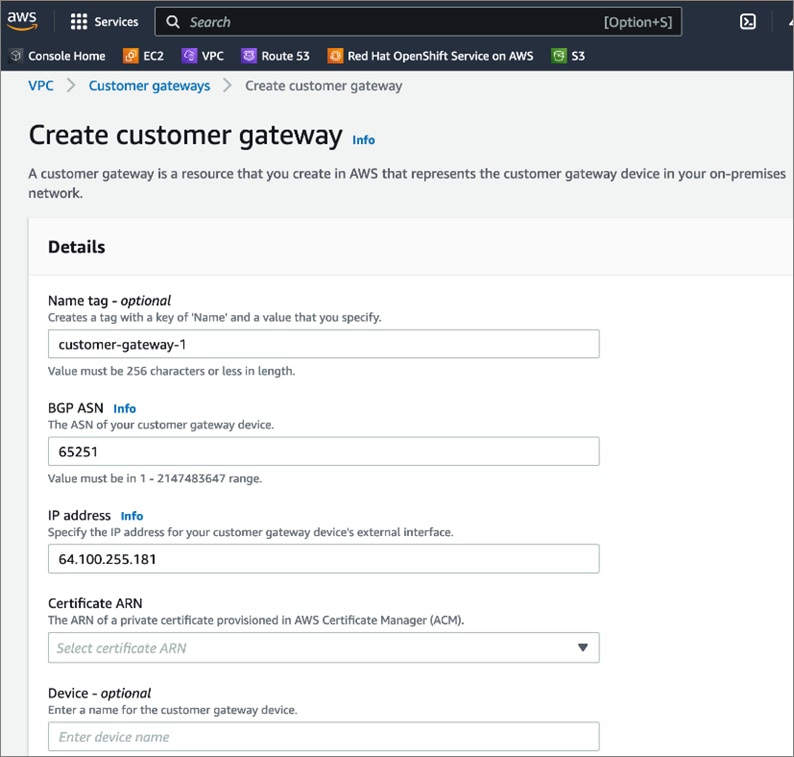
Step 4. Scroll down to the bottom and click Create customer gateway.
Step 5. Repeat steps 1-4 for the second on-prem gateway.
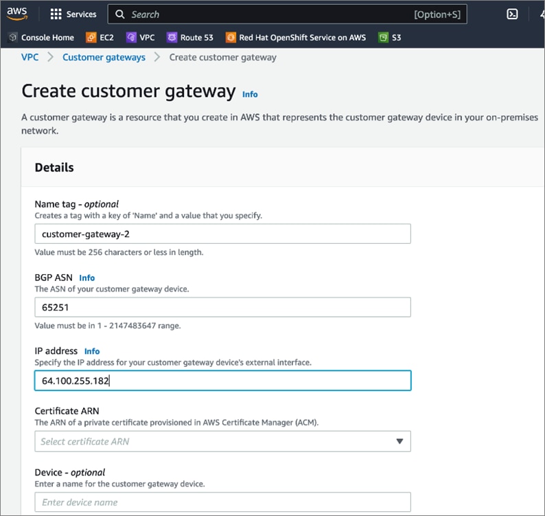
Procedure 4. Create TGW attachment to the Site-to-Site VPN
Step 1. Use a web browser to navigate to console.aws.amazon.com. Login to your AWS account.
Step 2. Navigate to VPC > Transit gateways attachments from the left navigation pane.
Step 3. Click Create transit gateway attachment.
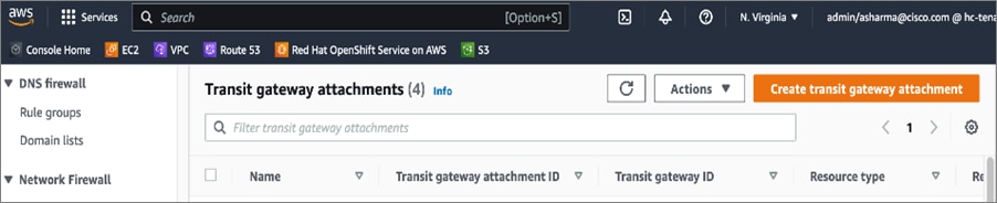
Step 4. In the Create transit gateway attachment window, specify a Name tag (for example, HC-TGW-VPN-Attachment). For the Transit gateway id, select the newly created TGW from the drop-down list. For the Attachment type, select VPN.
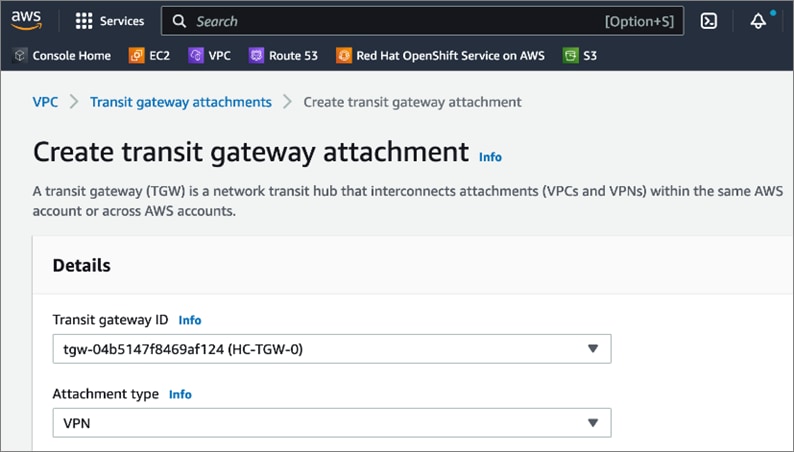
Step 5. In the VPN Attachment section, for Customer gateway, select the radio button for Existing. For Customer gateway ID, select the first customer gateway from the drop-down list. For Routing Options, select Static.
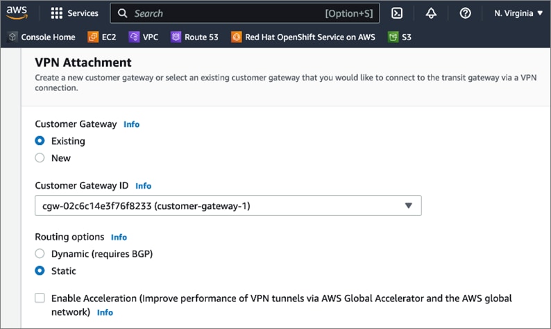
Step 6. Scroll down to the bottom and click Create transit gateway attachment.
Step 7. Repeat steps 1-6 to create a second TGW attachment to second customer gateway.
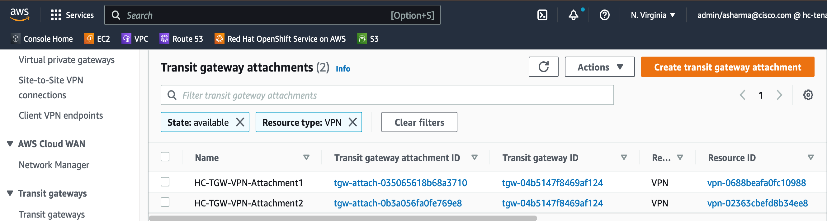
Procedure 5. Create Site-to-Site VPN to on-prem data center
Step 1. Use a web browser to navigate to console.aws.amazon.com. Login to your AWS account.
Step 2. Navigate to VPC > Site-to-Site VPN connections from the left navigation pane.
Step 3. Click Create VPN connection.
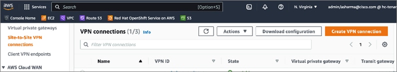
Step 4. In the Create VPN connection window, specify a name in Name tag, for the Target gateway type, select Transit gateway, and for the Transit Gateway, select the newly created Transit Gateway from the drop-down list.
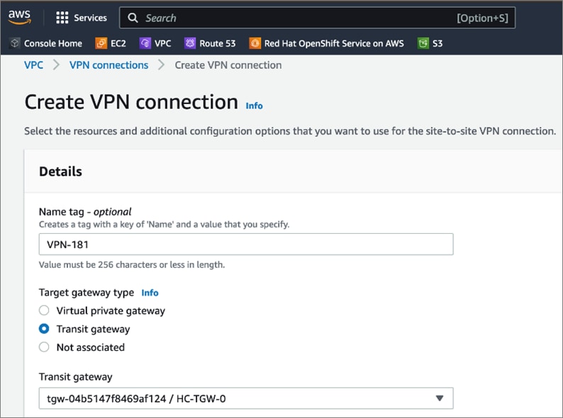
Step 5. For the Customer gateway, select Existing. For the Customer gateway ID, select the first gateway from the drop-down list. For the Routing options, select Static. For the Tunnel inside IP version, select IPv4.
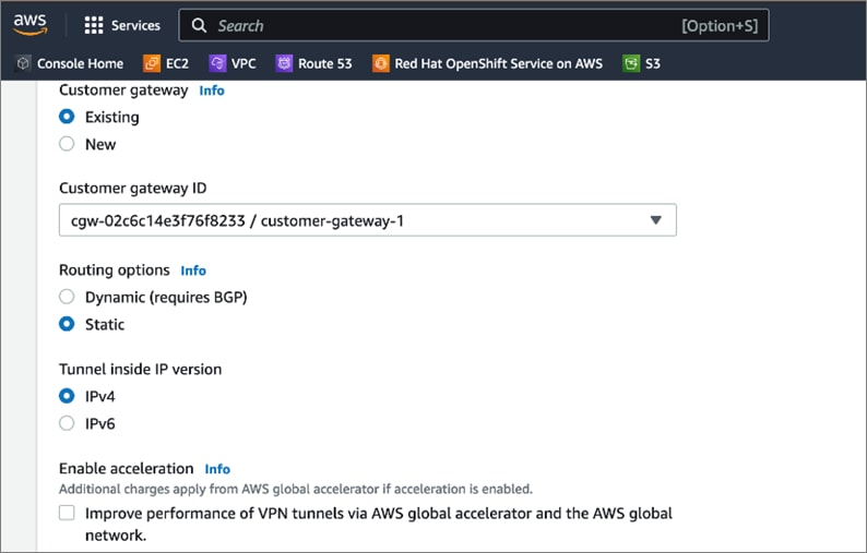
Step 6. Select default options for the IPs on either side allowed over the site-to-site VPN. Default allows all traffic. Restrict as needed for your environment.
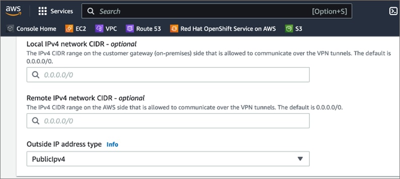
Step 7. Expand Tunnel 1 options and under Advanced options for tunnel 1, select Edit tunnel 1 options. This will enable several configuration options. For Phase 1 DH group numbers, delete 2 by clicking on the X next 2. Similarly, delete 2 from Phase 2 DH group numbers.
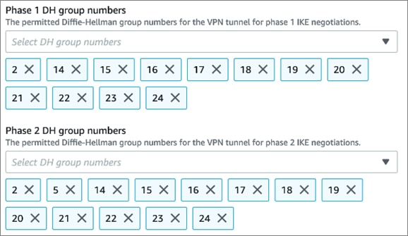
Step 8. For Startup action, select Start to specify the action to take for establishing a new (or modified) VPN tunnel. This is only supported for customer gateways with IP addresses.

Step 9. Under Tags, specify a name for connection using Key (Name) and Value.
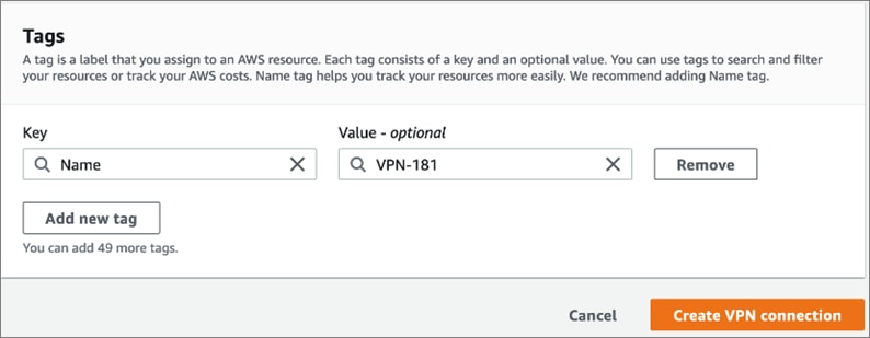
Step 10. Click Create VPN connection to create the VPN tunnel on the AWS side.
Step 11. Repeat Steps 1-10 for the second customer gateway.
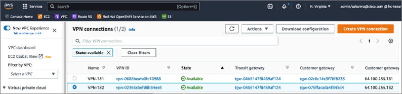
Procedure 6. Download site-to-site VPN configuration for on-prem device
Step 1. From VPC > Site-to-Site VPN, click the newly deployed VPN configuration for the first customer gateway.
Step 2. From the configuration for the VPN, click Download Configuration.
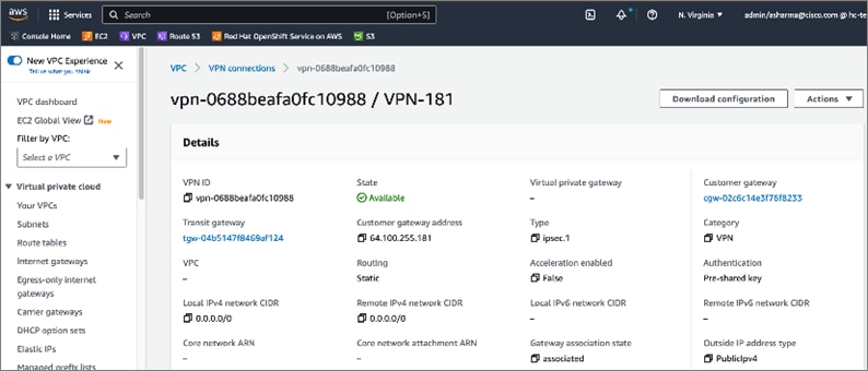
Step 3. In the Download configuration pop-up window, for Vendor, select Cisco Systems, Inc. For Platform, select CSRv AMI. For Software, select 12.4+. For IKE version, select ikev2.
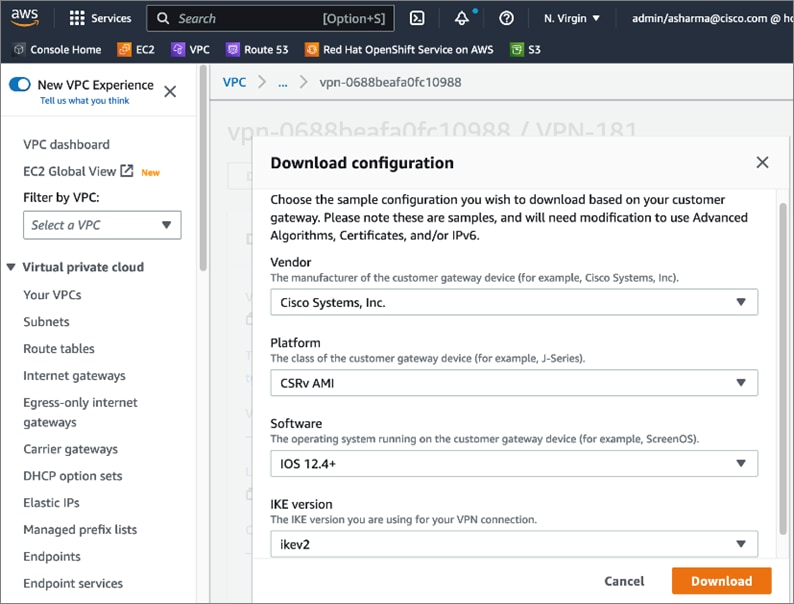
Step 4. Click Download.
Step 5. Repeat steps 1-4 for the VPN connection to the second customer gateway.
Step 6. Edit the downloaded configuration files and upload it to the on-prem VPN devices. The VPN devices are CSR1000V in this design. The edited configuration is provided in the Appendix section of this document.
Step 7. Enterprises must allow inbound reachability from the public IP of the AWS VPN tunnel to the public IP (if NAT is used, then to the private IP of the customer gateways. If NAT is used, then to the private IP of the customer gateways. This is the minimum configuration necessary to bring the IPsec VPN tunnel up. Verify that this connectivity is in place by initiating a ping from the customer gateways within the Enterprise to the public IP of the tunnel in AWS. Verify for both customer gateways – configuration and verification for customer gateway-1 is shown below.
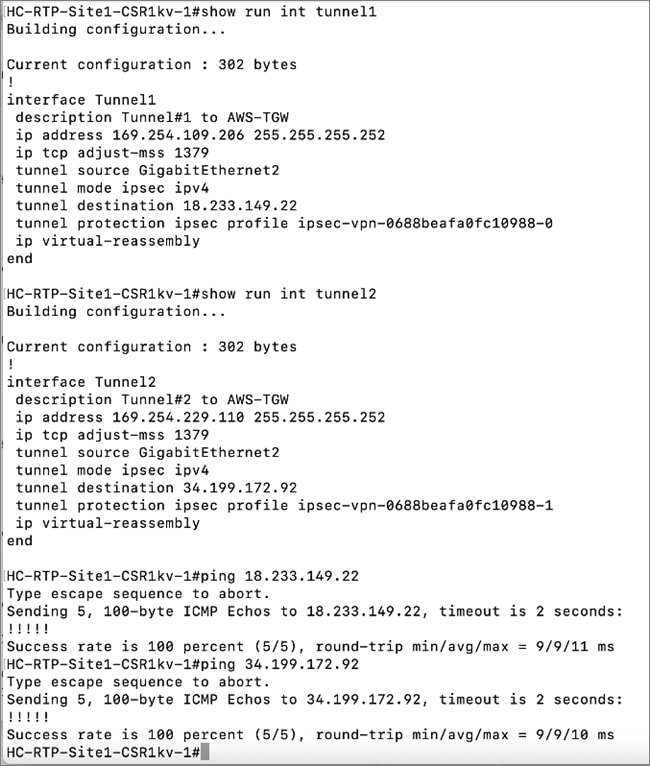
Step 8. Verify the site-to-site VPN tunnels are up on both locations as shown below.
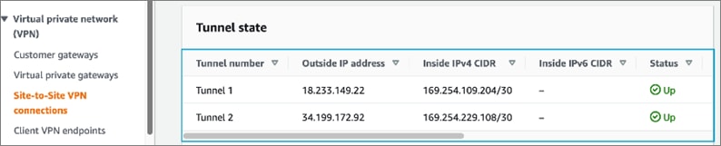
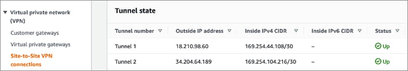
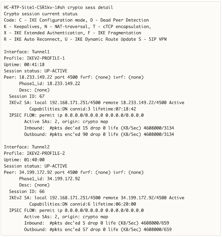
Note: Enterprise side Status of Site-to-Site VPN on VPN Gateway-2
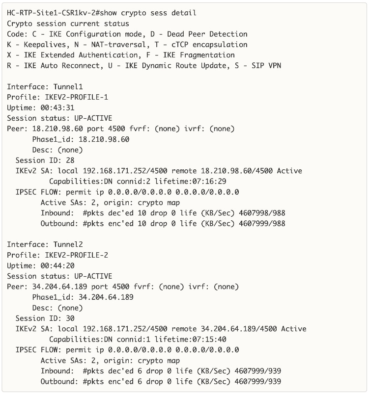
Step 9. Verify you have IP reachability between on-prem endpoints and AWS VPC endpoint. To verify this quickly, a temporary loopback IP and address is configured on the Enterprise gateways, and then a static route to the /32 IP of these loopbacks are added in the route table of the AWS Transit Gateway. Now you should be able to ping from the Loopback0 IP to any of the cluster nodes in AWS.
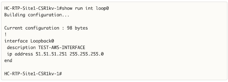
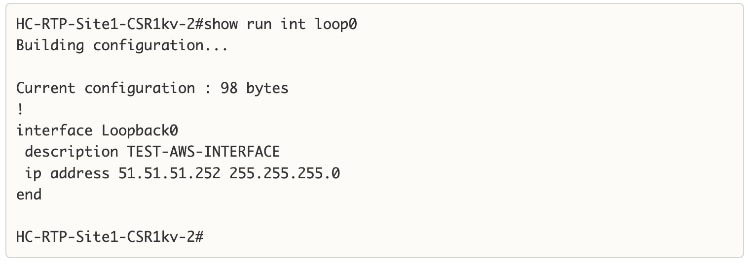
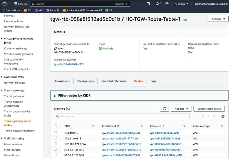
Note: You need to allow ICMP traffic from the Loopback IPs by adding a security group rule in the security group for master nodes/worker nodes or other endpoints that you want to allow ping access to as shown below.
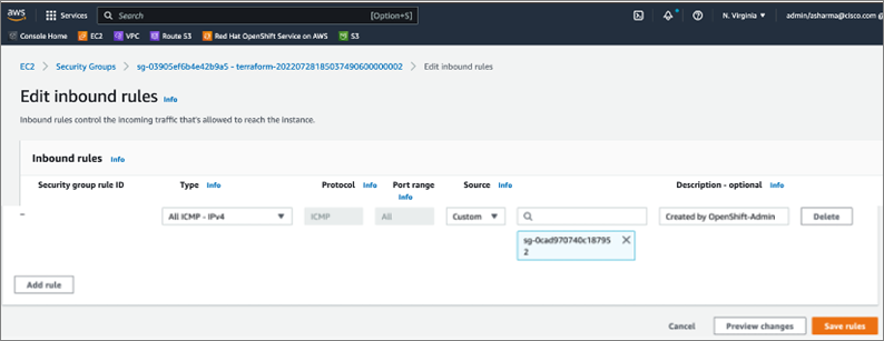
Step 10. You can now add additional routes as needed for reachability across this site-to-site VPN for applications, services, and other networks across this hybrid deployment.
This section describes the deployment of a Container Storage Interface (CSI) for the on-prem Kubernetes environment in the solution. This solution uses VMware vSphere CSI, which is one of the default CSIs deployed by Red Hat as a part of the OCP installation process. VMware vSphere CSI is deployed on the Red Hat OCP cluster running on the Application HyperFlex VSI cluster and will leverage HyperFlex as the physical storage for the backend VMDK volumes. The deployment steps provided here will focus on the additional configuration required to setup and use vSphere CSI to dynamically provision persistent storage for container workloads.
Prerequisites
The prerequisites for deploying VMware vSphere CSI on a Red Hat OCP cluster are:
● VMware vSphere version 6.7U3 or later
● Virtual machines of hardware version 15 or later
● No third-party vSphere CSI driver already installed in the cluster. Red Hat OCP includes a built-in version of the vSphere CSI in each OCP release. Red Hat only supports this CSI and does not support a vSphere CSI provided by the vendor or by the community.
● VMware vCenter and vSphere version should ideally be the same version or certain capabilities may not be available – see the VMware vSphere CSI documentation for additional details.
Setup Information
Table 13 lists the deployment parameters for VMware vSphere CSI.
Table 13. VMware vSphere CSI – Deployment Parameters
| Variable |
Variable Name |
Value |
Additional Info |
| Storage Class Name |
name |
thin-csi |
Provisioned during OCP install |
| Storage Policy Name |
StoragePolicyName |
openshift-storage-policy-ocp11-9kbbs |
Provisioned during OCP install – note that ocp11-9kbbs is the cluster name prefix |
| Storage Provisioner |
provisioner |
csi.vsphere.vmware.com |
|
| Storage Reclaim Policy |
reclaimPolicy |
Delete |
Default – but can be changed to ‘Reclaim’ as needed |
| Volume Binding Mode |
volumeBindingMode |
WaitForFirstConsumer |
Default – here the binding is not done until a Pod makes a Persistent Volume Claim |
| Allow Volume Expansion ??? Same as CSI resize ??? |
allowVolumeExpansion |
true |
Provisioned during OCP install |
Deployment Steps
The section provides the procedures for deploying and using VMware vSphere CSI on a Red Hat OCP cluster running on the Application HyperFlex VSI cluster.
Procedure 1. Verify built-in vSphere CSI deployment and configuration
This procedure verifies that the VMware vSphere CSI that was deployed as a part of the Red Hat OCP install. Red Hat OCP Installer deploys the vSphere CSI in the openshift-cluster-storage-operator and openshift-cluster-csi-drivers namespaces or projects. Verify the CSI pods are up and running with no errors. This can be verified from the command line or from Red Hat Hybrid Cloud Console.
Step 1. Navigate using a web browser to the OpenShift Hybrid Cloud Console. Login using your Red Hat account. Navigate to Clusters and find the newly created OCP cluster. Click the cluster name.
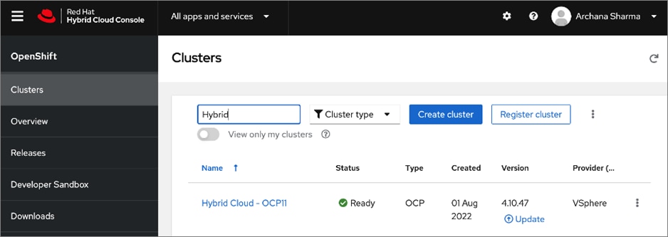
Step 2. Click on Open console from the top-right corner and login to the cluster console as kubeadm user.
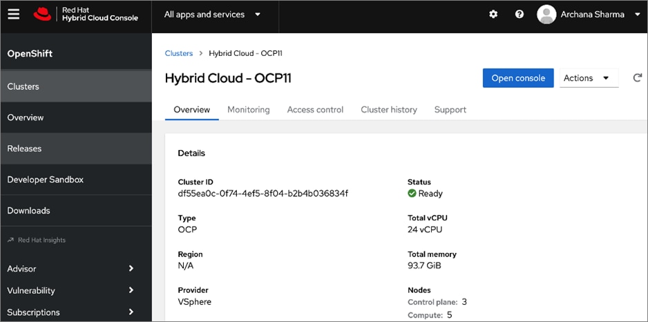
Step 3. From the Red Hat OCP console for the cluster, navigate to Home > Projects in the left navigation menu. Select and click openshift-cluster-storage-operator from the list.
Step 4. Review the inventory and verify that all Pods, containers, and services are running. Verify there are no CSI related errors in the Status window.
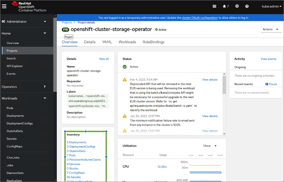
Step 5. Repeat step 2 for the second namespace/project: openshift-cluster-csi-drivers
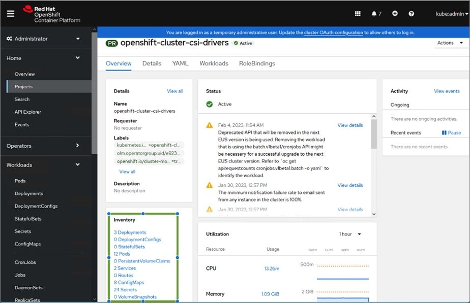
Note: You can also quickly verify the status of the pods from the command line as shown below:
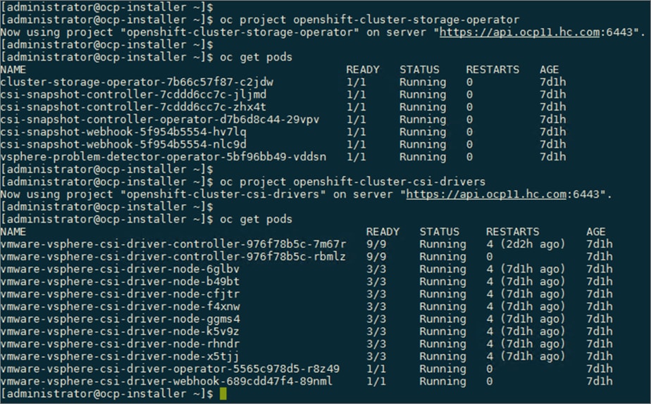
Procedure 2. Review the VMware vSphere CSI storage class deployed by the OCP installer
Step 1. From the Red Hat OCP console for the cluster, navigate to Storage > Storage Classes in the left navigation menu.
Step 2. Select and click thin-csi from the list. This is the VMware vSphere CSI driver plugin.
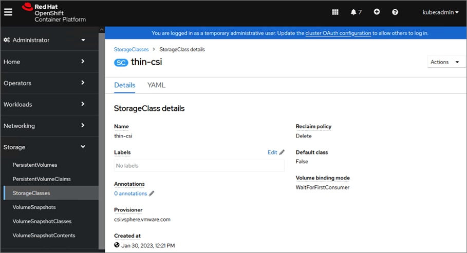
Step 3. Click the YAML tab in the right window to view the storage class configuration.
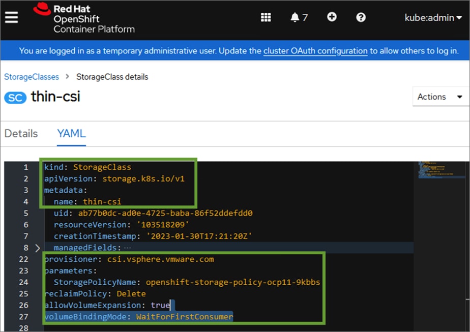
Step 4. Review and edit options as needed – for example, the storage reclaim policy.
Procedure 3. Make VMware vSphere CSI the default CSI for Pods
By default, the Red Hat OCP installation process deploys multiple storage drivers. Kubernetes pods can use the associated storage class to request persistent storage from the backend storage.
Step 1. From the Red Hat OCP console for the cluster, navigate to Storage > Storage Classes in the left navigation menu. The storage classes associated with the storage drivers deployed by the Red Hat OCP installation process is shown below.
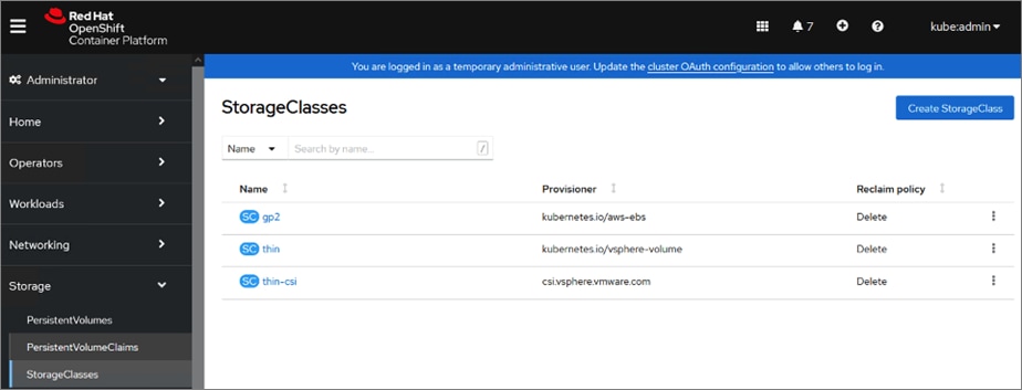
Step 2. Select and click thin-csi from the list. This is the VMware vSphere CSI driver plugin. The other vSphere storage class is for the earlier in-tree vSphere driver/plugin.
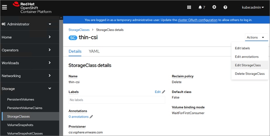
Step 3. Click Actions and select Edit StorageClass from the drop-down list.
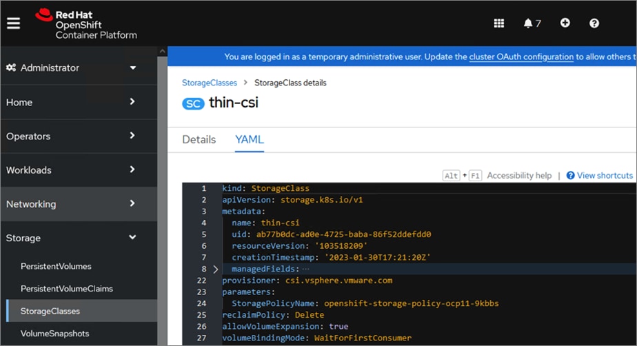
Step 4. Add the highlighted annotations to the metadata section of the storage class configuration. See next step.
apiVersion: storage.k8s.io/v1
kind: StorageClass
metadata:
annotations:
storageclass.kubernetes.io/is-default-class: "true"
kubernetes.io/description: 'Default SC - vSphere CSI'
Step 5. Click Actions and then select Edit annotations from the drop-down list. In the Edit annotations pop-up window, specify the above information as a Key, Value pair as shown below. Click Save to close the pop-up window
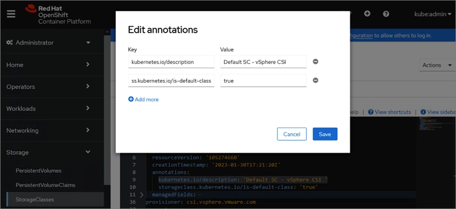
Step 6. From the YAML view, click Save and then Reload to apply the changes. The changes should now be applied and reflected in the configuration.
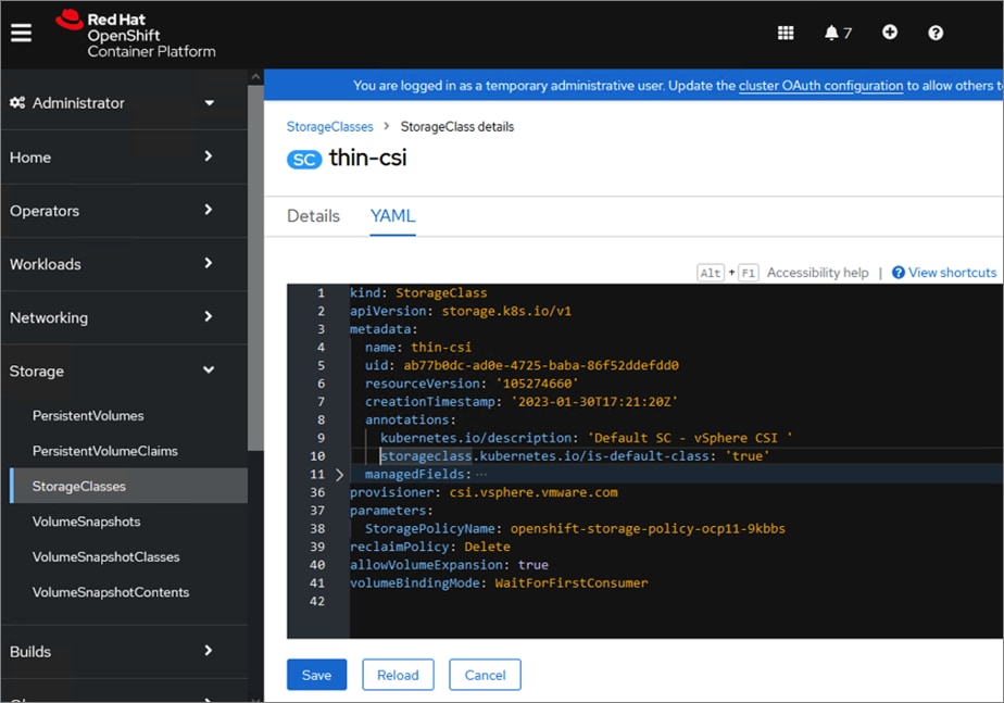
Step 7. The Storage > Storage Classes in the left navigation menu should now show (- Default) next to the vSphere CSI.
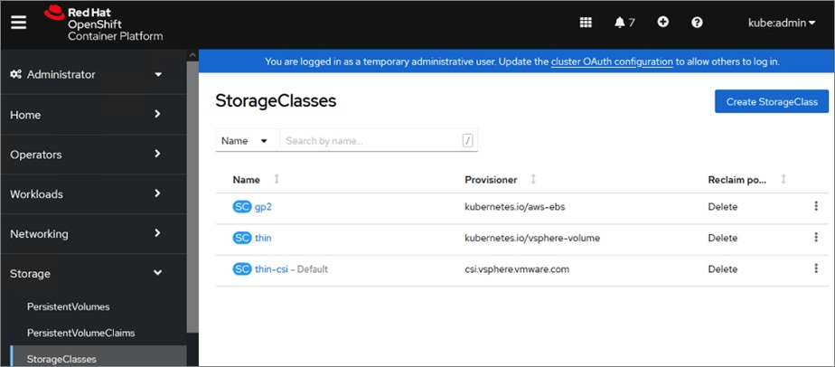
Procedure 4. Verify the CSI driver by deploying an application that requires persistent storage
The application we will use as an example (pacman) is deployed from the command line using Helm charts.
Step 1. From a workstation with access to the Red Hat OCP cluster and where the CLI tools are deployed as a part of the OCP installation, create a new Openshift project or namespace to deploy the sample application.
oc new-project app-pacman-staging
Step 2. Add the repo to access the helm charts for deploying the application.
helm repo add veducate https://saintdle.github.io/helm-charts/
Step 3. Deploy the application.
helm install pacman veducate/pacman -n app-pacman-staging --set scc.create=true
Step 4. The sample application is deployed as shown below.
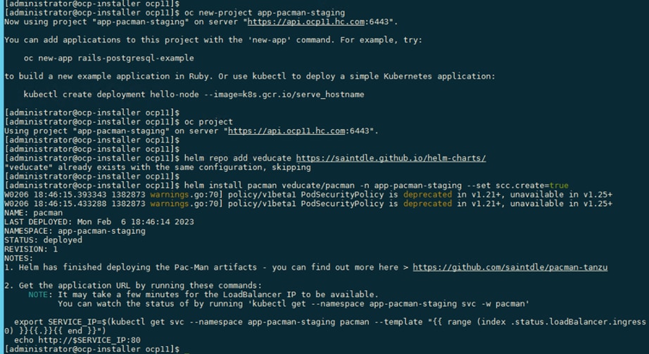
Step 5. Verify that the application pods and containers are up and running without any errors.
oc get all, oc get pods
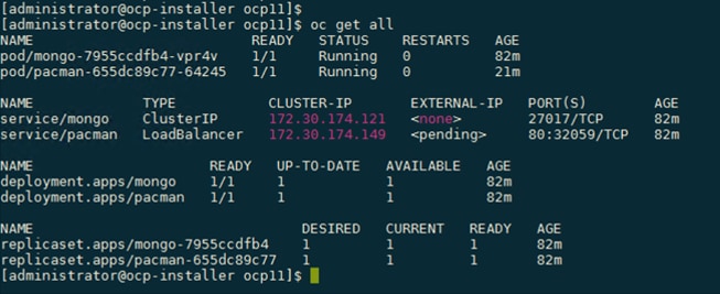
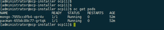
Step 6. Verify that the persistent volume claim (PVC) by the sample application is successful.
oc get pvc, oc describe pvc <pvc_name>
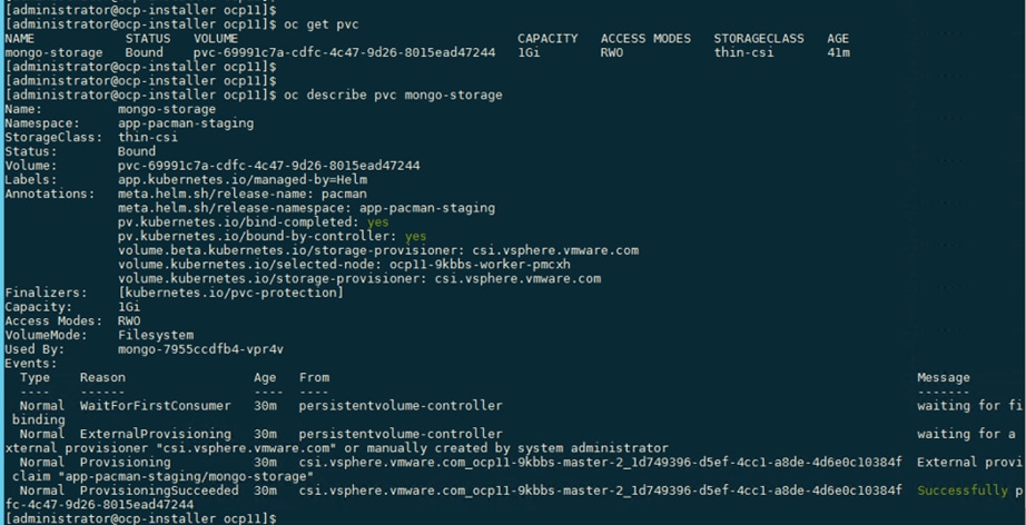
oc get pv | grep thin-csi, oc describe pv <pv_name>
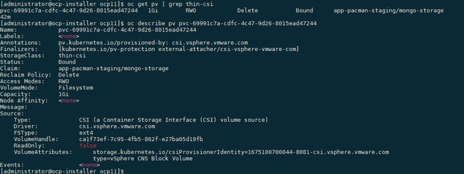
oc get volumeattachments, oc describe volumeattachments <volume_attachment_name>

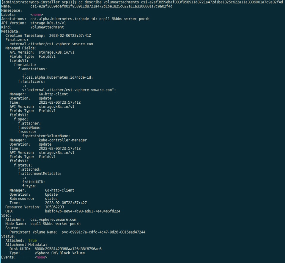
Procedure 5. Create Volume Snapshot Class using VMware vSphere CSI
Step 1. From the Red Hat OCP console for the cluster, navigate to Storage > VolumeSnapshotClasses in the left navigation menu.
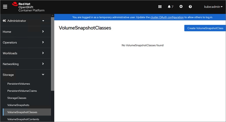
Step 2. Click Create VolumeSnapshotClass. In the right-hand side window, edit the YAML file with a name for the volume snapshot class (for example, vsphere-csi-snapshotclass) and name of the vSphere CSI drive (cs.vsphere.vmware.com). Click Create.
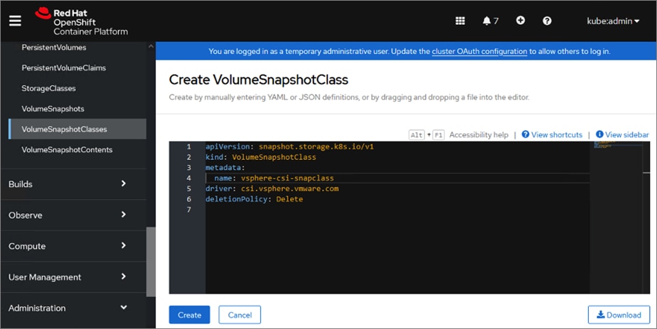
Step 3. For Kasten K10 that will be deployed later in the solution, add the following annotation to the metadata for the volume snapshot class. See next step for the procedure.
metadata:
annotations:
k10.kasten.io/is-snapshot-class: "true"
Step 4. Click Actions and select Edit annotations from the drop-down list.
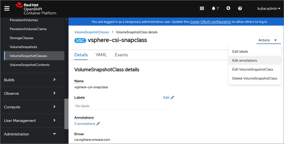
Step 5. Add the annotation as a key, value pair as shown. Click Save.
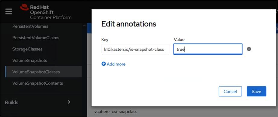
The resulting YAML configuration for the volume snapshot class is as shown below:
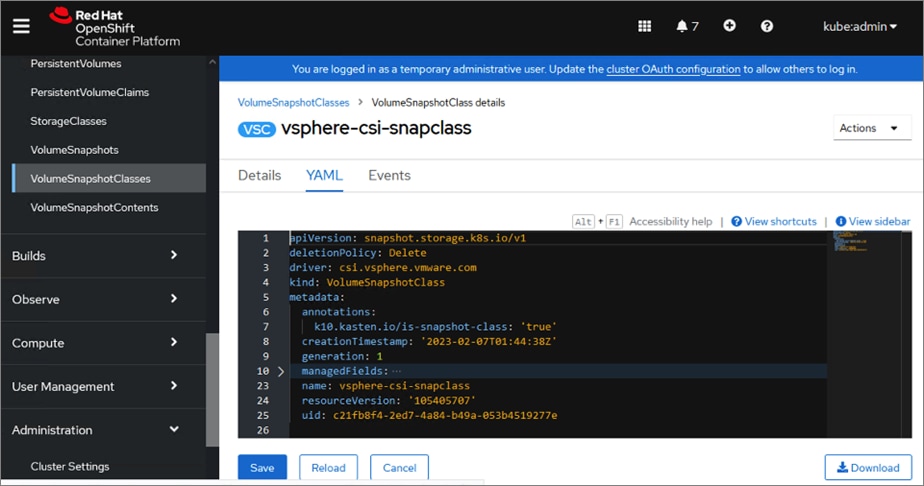
This section describes the deployment of Kasten K10 on a Red Hat OCP cluster running on a HyperFlex VSI in an Enterprise data center to support hybrid cloud use cases such as backup/restore of persistent volumes and application mobility from cloud to on-prem or vice-versa.
Prerequisites
The prerequisites for deploying Kasten K10 with vSphere CSI on a Red Hat OCP cluster are:
● VMware vSphere 7.0 U1 or higher
● Access to VMware vCenter from Kasten K10
● CSI supports Volume Snapshots
● Back-end storage is provisioned.
● StorageClass is defined and backed by high-performance storage. This can be the default StorageClass, or one can be specified during Kasten K10 deployment.
● Volume Snapshot Class provisioned with the following K10 annotation: k10.kasten.io/is-snapshot-class: "true"
● CSI Driver container: csi-snapshotter is version 1.2.2 or higher
Setup Information
Table 14 provides the setup information for deploying Kasten K10 on an on-prem OCP cluster running HyperFlex VSI.
Table 14. Deployment Parameters
| Variable |
Variable Name |
Value |
Additional Info |
| OCP Cluster |
APPS_BASE_DOMAIN |
apps.ocp11.hc.com |
|
| OCP Cluster |
API_BASE_DOMAIN |
api.ocp11.hc.com |
|
Deployment Steps
The section provides the procedures for deploying Kasten K10 on the on-prem Red Hat OCP cluster running on a HyperFlex VSI cluster and using VMware vSphere CSI to provision persistent storage and related functionality.
Procedure 1. Run Kasten Pre-flight checks using the K1 primer tool
This procedure runs the Kasten pre-flight checks to ensure the pre-requisites are setup correctly.
Step 1. Verify that your oc or kubectl context is pointing to the cluster where you will be deploying Kasten K10. Use the following command to verify.
oc get nodes
Step 2. Deploy the K10 primer tool to verify there are no errors. For air-gapped deployments, see Kasten documentation.
curl https://docs.kasten.io/tools/k10_primer.sh | bash
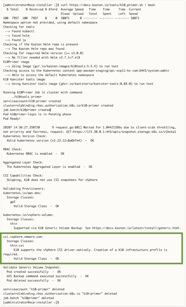
Step 3. For a more complete CSI validation (recommended), run the primer cool with a specific storage class (for example, thin-csi)
curl -s https://docs.kasten.io/tools/k10_primer.sh | bash /dev/stdin -s thin-csi
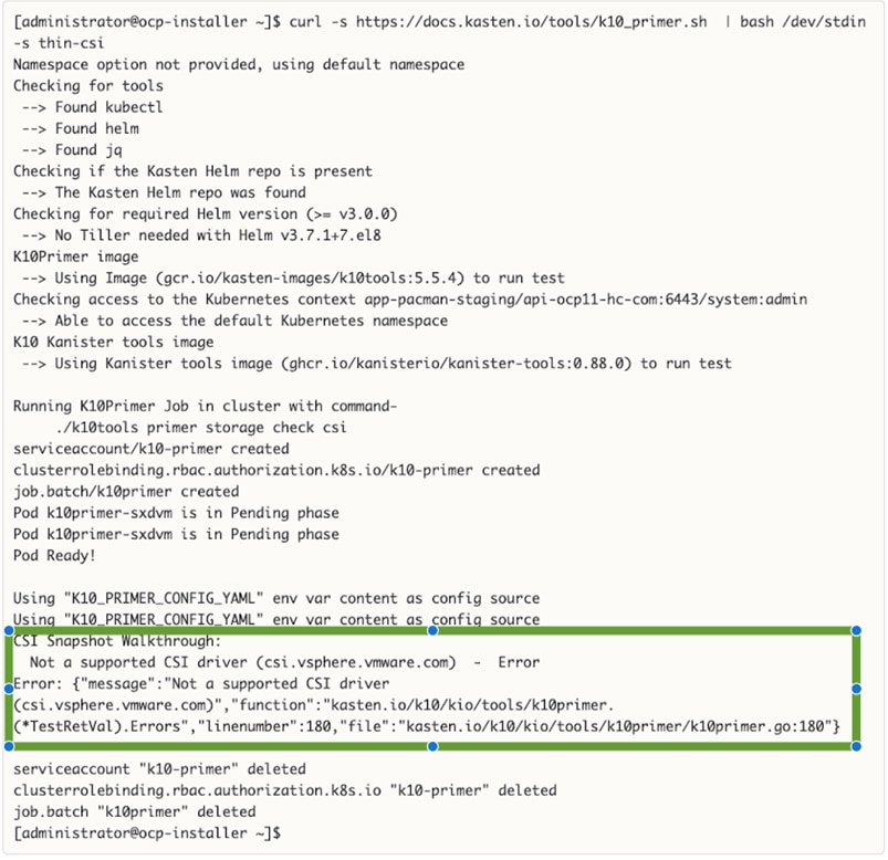
Note: The primer tool for a more complete CSI validation will fail for VMware vSphere CSI until Kasten is deployed and an Infrastructure profile is configured enabling Kasten to communicate directly with VMware vCenter due to the enhanced integration that Kasten K10 provides with VMware.
Procedure 2. Deploy Kasten K10 using a Helm chart
Step 1. Use the following command to add the repo for Kasten Helm charts:
helm repo add kasten https://charts.kasten.io/
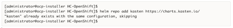
Step 2. Create a namespace or OCP project for deploying Kasten K10. Kasten documentation uses kasten-io for the namespace/project name. Create a project or a namespace using one of these commands:
oc new-project kasten-io
kubectl create namespace kasten-io
Step 3. Bypass Security Context Constraints - use with care and only if needed. For more information on SCC in Red Hat OCP, see: https://cloud.redhat.com/blog/managing-sccs-in-openshift
oc adm policy add-scc-to-group anyuid system:authenticated
Step 4. Configure the following variables based on the Red Hat OCP cluster settings.
APPS_BASE_DOMAIN=apps.ocp11.hc.com
API_BASE_DOMAIN=api.ocp11.hc.com

Step 5. Create a service account as follows. An OAuth client will now be registered with OpenShift:
cat > oauth-sa.yaml <<EOF
apiVersion: v1
kind: ServiceAccount
metadata:
name: k10-dex-sa
namespace: kasten-io
annotations:
serviceaccounts.openshift.io/oauth-redirecturi.dex: https://example.com/k10/dex/callback
EOF
oc create -f oauth-sa.yaml
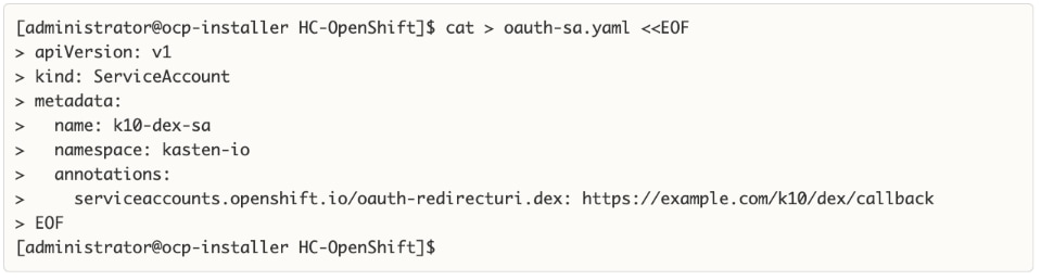
Step 6. Creation of the service account automatically results in two secrets being added. Collect the name of the secret containing the token.
oc get sa k10-dex-sa -n kasten-io -o yaml
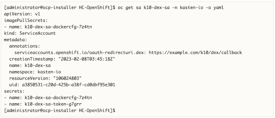
Step 7. If the secret containing the token is the first file in the output above, use index [0] to collect the token as shown in the first command below. If it is the second file, use index [1] or the second command below.
# token is first file
DEX_TOKEN=$(oc -n kasten-io get secret $(oc -n kasten-io get sa k10-dex-sa -o jsonpath='{.secrets[0].name}') -o jsonpath='{.data.token}' | base64 -d)
# token is second file
DEX_TOKEN=$(oc -n kasten-io get secret $(oc -n kasten-io get sa k10-dex-sa -o jsonpath='{.secrets[1].name}') -o jsonpath='{.data.token}' | base64 -d)
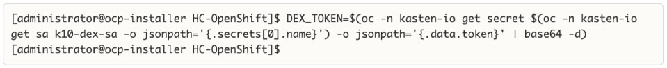
Step 8. Verify the token using the following command. Output below is truncated.
echo $DEX_TOKEN
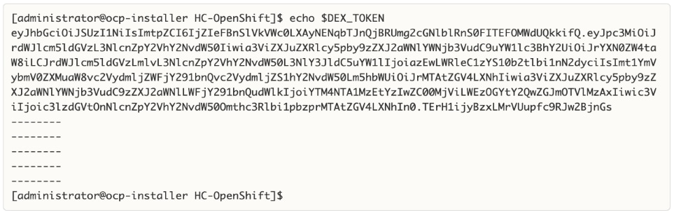
Step 9. If the Red Hat OCP installation does not have a valid certificate for the router, signed by a public Certificate Authority (for example, Verisign), execute the commands below to add the Certificate Authority that is used to the trust-store of the Kasten Pods. The first command will extract the certificate into a pem file (custom-ca-bundle.pem). The second command will create the config map and add the certificate.
oc get secret router-ca -n openshift-ingress-operator -o jsonpath='{.data.tls\.crt}' | base64 --decode > custom-ca-bundle.pem
oc --namespace kasten-io create configmap custom-ca-bundle-store --from-file=custom-ca-bundle.pem
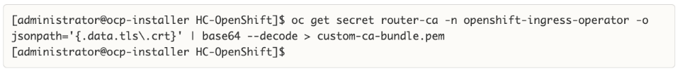
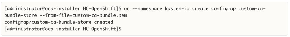
Step 10. Install Kasten K10 using the following Helm options:
helm install k10 kasten/k10 --namespace=kasten-io \
--set scc.create=true \
--set route.enabled=true \
--set route.tls.enabled=true \
--set auth.openshift.enabled=true \
--set auth.openshift.serviceAccount=k10-dex-sa \
--set auth.openshift.clientSecret=${DEX_TOKEN} \
--set auth.openshift.dashboardURL=https://k10-route-kasten-io.${APPS_BASE_DOMAIN}/k10/ \
--set auth.openshift.openshiftURL=https://${API_BASE_DOMAIN}:6443 \
--set auth.openshift.insecureCA=true \
--set cacertconfigmap.name=custom-ca-bundle-store
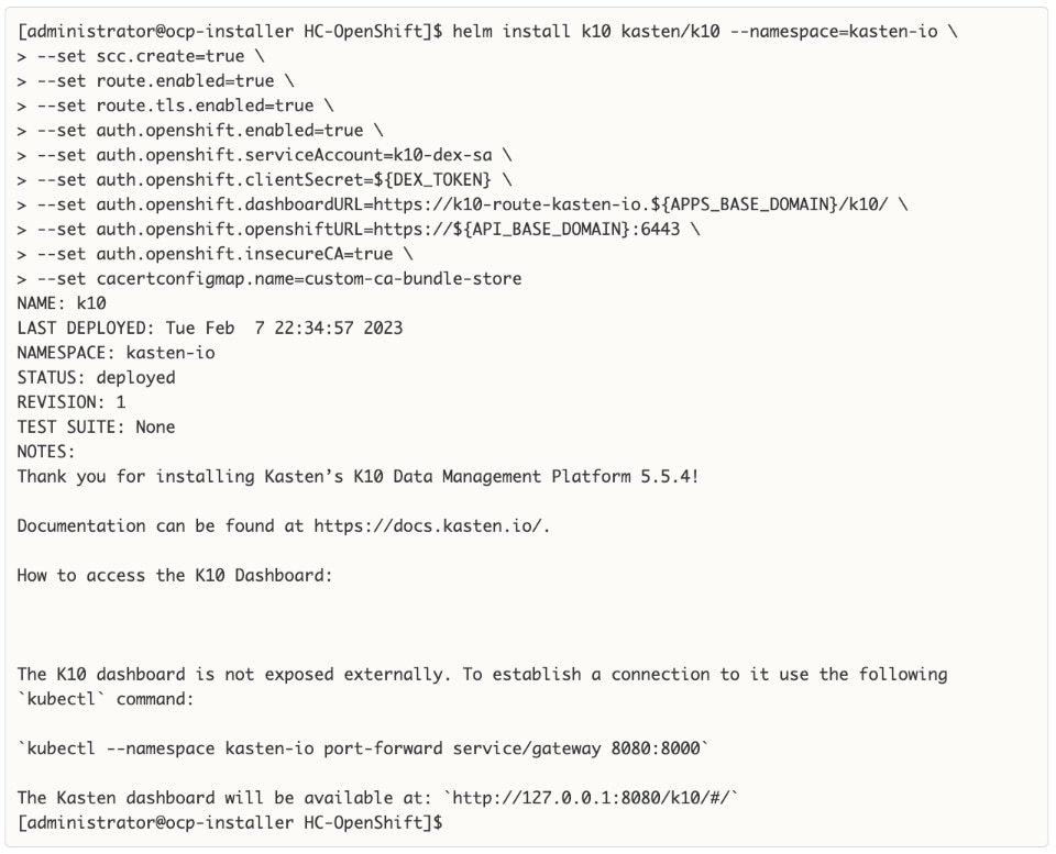
Step 11. Download and extract the k10tools available here to verify that the authentication service was setup correctly. This should be run from the directory where the custom-ca-bundle-store.pem is located.
./k10tools debug auth -d openshift
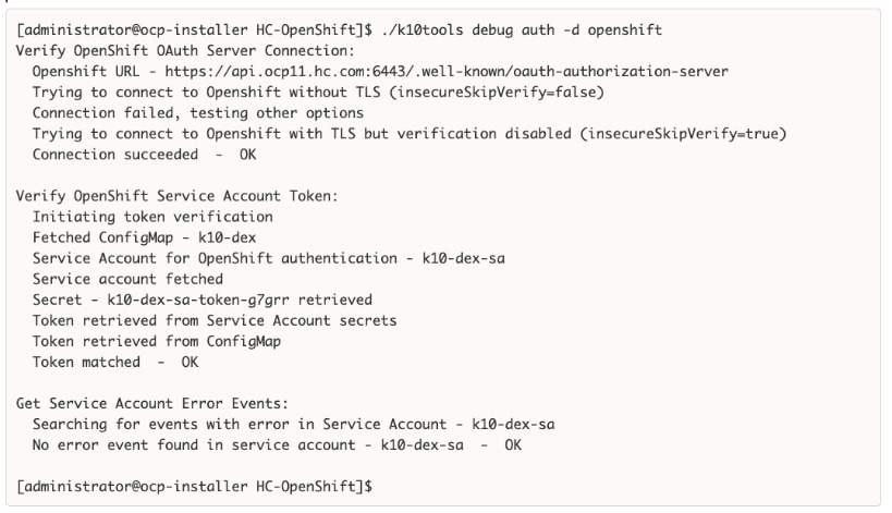
Step 12. Verify access to the Kasten dashboard using the first command. You will be redirected the second link .
https://k10-route-kasten-io.apps.ocp11.hc.com/k10/
https://k10-route-kasten-io.apps.ocp11.hc.com/k10/#/dashboard
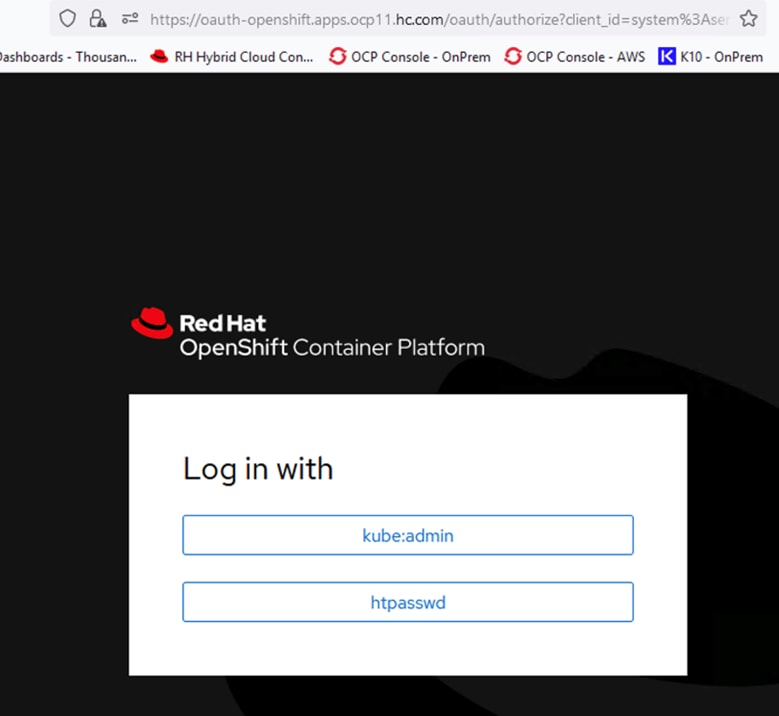
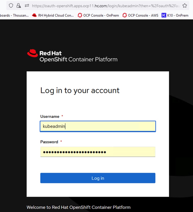
Step 13. Specify email address, company name, and accept terms.
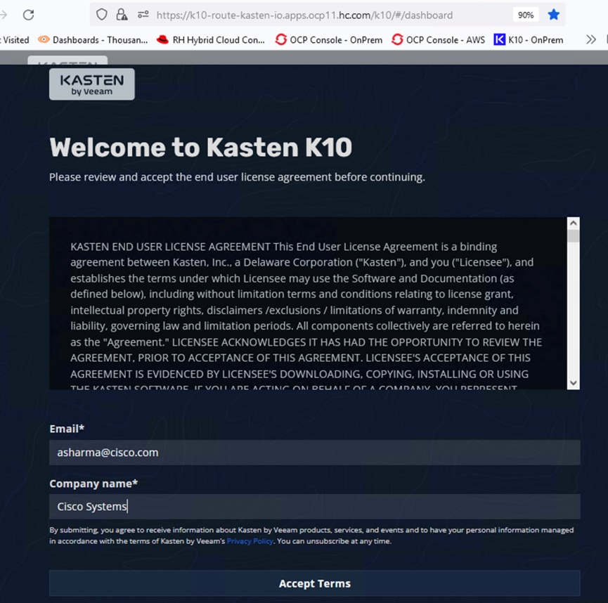
Step 14. Verify that Kasten was deployed successfully and there no errors accessing the dashboard.
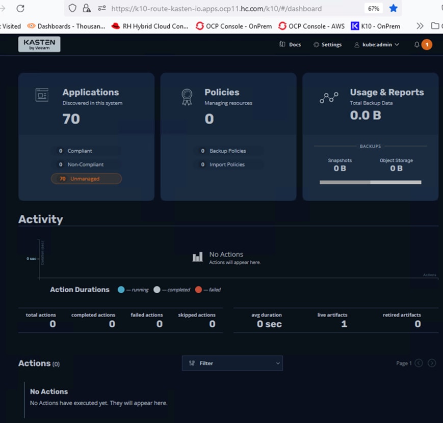
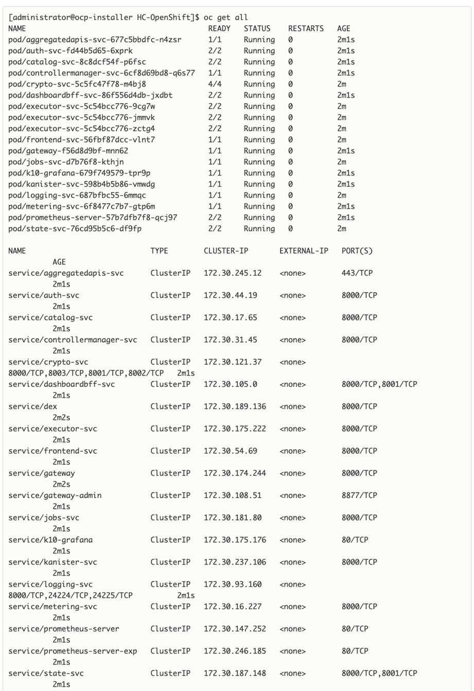
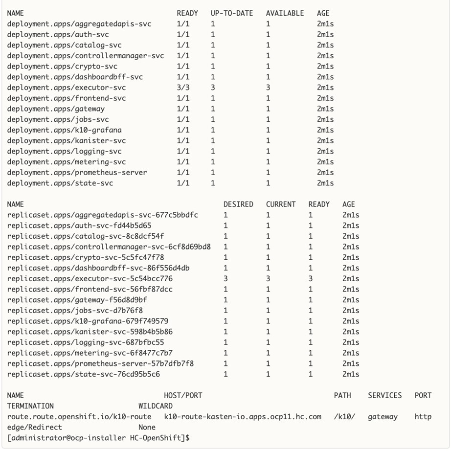
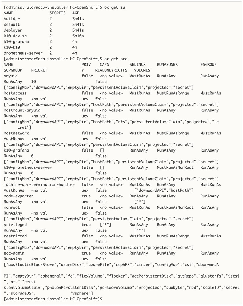
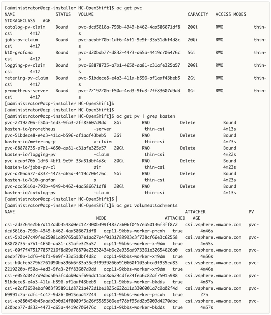
Step 15. If you need to repeat the above steps for any reason, use the following command to uninstall Kasten.
helm uninstall k10 --namespace=kasten-io
oc delete project kasten-io
Enable Volume Snapshots using Kasten and VMware vSphere CSI (On-Prem)
With Kasten K10 deployed, the next step is to enable volume snapshots to protect the persistent data. The snapshots can then be backed up using Kasten K10 to object storage, NFS, or Veeam repository. Using Kasten K10 to backup volume snapshots is useful even when the storage vendor provides durable snapshotting capabilities as it allows for higher resiliency by backing up the data in a different infrastructure (in this case to the public cloud). Application-level snapshots along with volume snapshots provide the highest resiliency and, using Kasten K10, both can be backed up to an object store in the public cloud.
Prerequisites
The prerequisites for the enabling volume snapshots using Kasten K10 and VMware vSphere CSI are:
● Red Hat OCP environment deployed and operational
● Persistent Storage using VMware vSphere CSI deployed and operational
● Kasten K10 deployed and operational
● AWS S3 Bucket has been provisioned for use as target for the on-prem backups.
Setup Information
Table 15 provides the setup information for enabling volume snapshots using vSphere CSI.
Table 15. Deployment Parameters
| Variable |
Variable Name |
Value |
Additional Info |
| VMware vCenter |
Hostname |
vc1-1.hc.com |
|
| VMware vCenter |
Username |
administrator@vsphere.local |
Account with Administrator Privileges |
| VMware vCenter |
Password |
<Specify password> |
|
| AWS |
Access Key |
<Specify> |
|
| AWS |
Secret |
<Specify> |
|
| AWS |
Region |
us-east-1 |
|
| AWS |
S3 Bucket Name |
ocp-kasten-backup |
|
| VMware vCenter |
Infrastructure Profile Name |
vmware-vc1-1-infra-profile |
This profile is created in Kasten |
| AWS 3 bucket |
Export Location Profile Name |
aws-export-profile |
Target for backups of volume and application snapshots and other data |
Deployment Steps
The section provides the procedures for enabling volume snapshots using Kasten K10 and VMware vSphere CSI.
Procedure 1. Create Infrastructure Profile for VMware vCenter
Step 1. From a web browser, navigate to the Kasten K10 dashboard.
Step 2. Go to Settings in the top right-corner of the window. Select and click Infrastructure from the menu on the left.
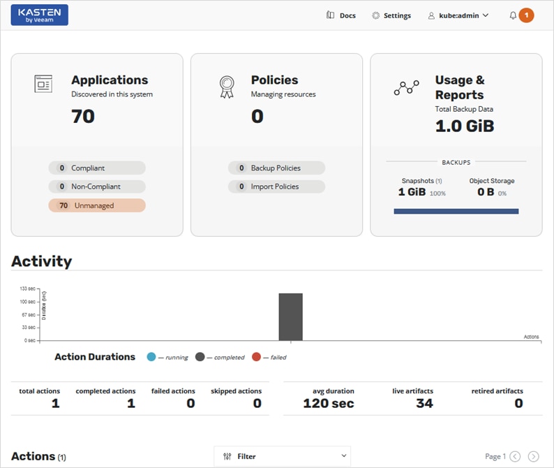
Step 3. Click New Profile to add a new Infrastructure Profile.
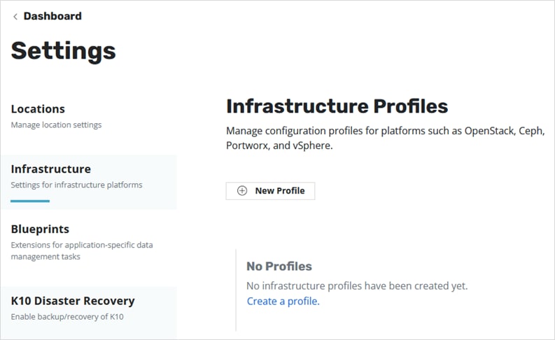
Step 4. Specify a Profile Name, select vSphere for the Infrastructure Type, specify the vCenter Server IP address or hostname, Enable Tagging (optional), and provide vSphere Username and Password.
Step 5. Click Save Profile.
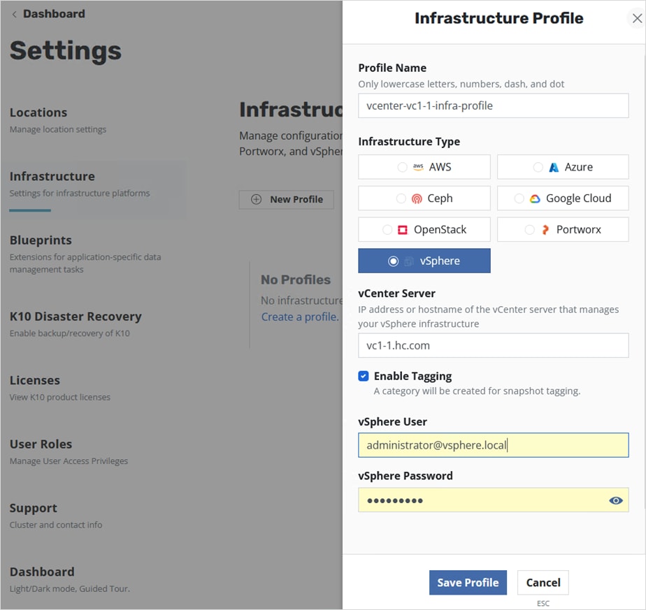
If the information provided is accurate and Kasten can access VMware vCenter, then the STATUS will show as Valid.
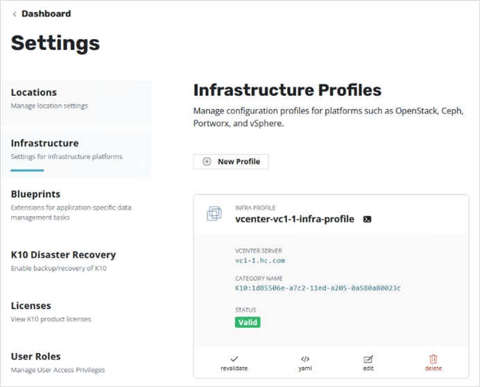
Step 6. Click Dashboard in the top left corner of the window to return to the main menu.
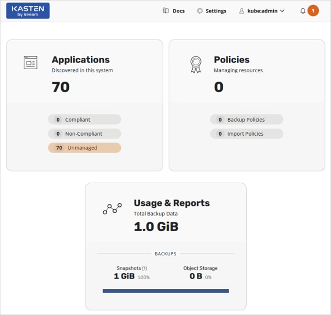
Step 7. Click anywhere in the Applications box.
Step 8. Click snapshot from the bottom menu of the application in the app-pacman-staging namespace.

Step 9. Click Snapshot Application on the bottom of the screen.
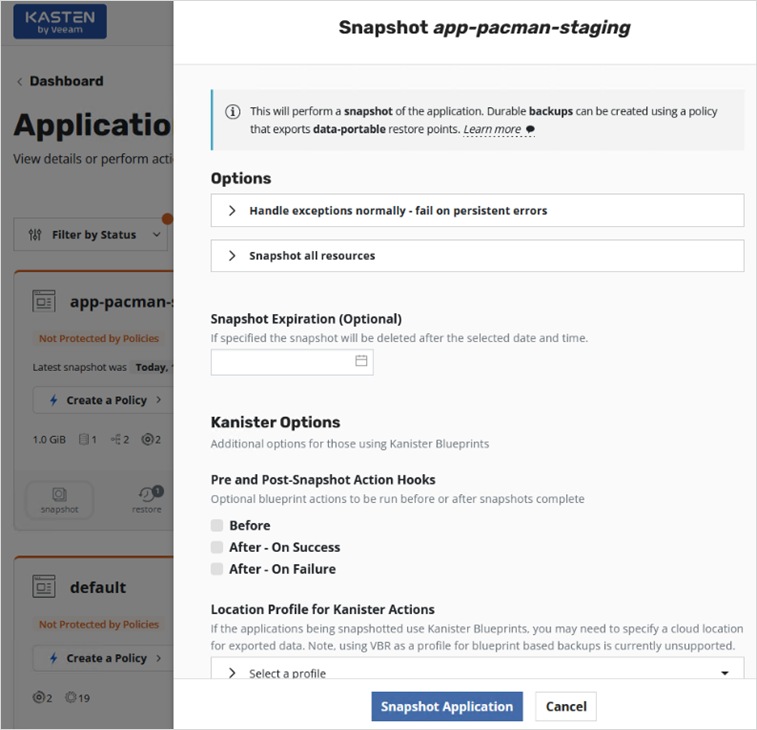
Step 10. Navigate to the main dashboard screen and scroll down to the bottom to the Actions section to view the progress of the snapshot.
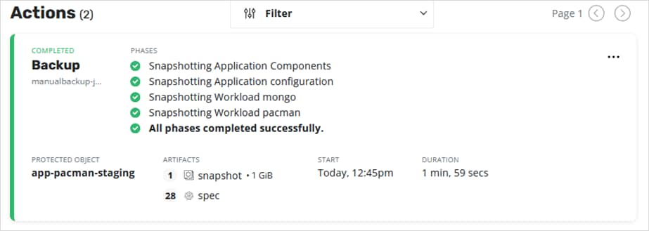
Step 11. The previous steps created a manual snapshot of a given application. See Backup and Restore in the Use Cases section of this document to configure a policy to automate the snapshot, backup, and export to an external object store or NFS file share.
Deploy Kasten K10 (Public Cloud)
This section describes the deployment of Kasten K10 on Red Hat OCP cluster in AWS to support hybrid cloud use cases such as backup/restore of persistent volumes and application mobility from cloud to on-prem or vice-versa.
Prerequisites
The prerequisites for deploying Kasten K10 on a Red Hat OCP cluster in AWS public cloud are:
● CSI supports Volume Snapshots
● Storage class is defined. This can be the default storage class, or one can be specified during K10 deployment.
● Persistent volume claim using the CSI is successful
● Volume Snapshot Class provisioned with the following K10 annotation: k10.kasten.io/is-snapshot-class: "true"
● AWS S3 bucket has been provisioned. This will serve as a backup target for the workloads running in the AWS public cloud
Setup Information
Table 16 provides the setup information for deploying Kasten on OCP cluster in AWS.
Table 16. Deployment Parameters
| Variable |
Variable Name |
Value |
Additional Info |
| AWS |
Access Key |
<Specify> |
|
| AWS |
Secret |
<Specify> |
|
| OCP Cluster |
APPS_BASE_DOMAIN |
apps.ocp11.hc-aws.com |
|
| OCP Cluster |
API_BASE_DOMAIN |
api.ocp11.hc-aws.com |
|
Deployment Steps
The section provides the procedures for deploying Kasten K10 on a Red Hat OCP cluster in the AWS public cloud and AWS CSI to provision persistent storage and related functionality.
Note: The deployment steps for Kasten on an OCP cluster in AWS is almost identical to that of on-prem covered in the Deploy Kasten K10 (On-Prem) section of this document. For this reason, this section will provide a summary of the steps and will not include outputs from executing the steps.
Procedure 1. Run Kasten Pre-flight checks using the K1 primer tool
This procedure runs the Kasten pre-flight checks to ensure the pre-requisites are setup correctly.
Step 1. Verify that your oc or kubectl context is pointing to the cluster where you will be deploying Kasten K10. Use the following command to verify.
oc get nodes
Step 2. Deploy the K10 primer tool to verify there are no errors. For air-gapped deployments, see Kasten documentation.
curl https://docs.kasten.io/tools/k10_primer.sh | bash
Step 3. For a more complete CSI validation (recommended), run the primer cool with a specific storage class (for example, gp2-csi)
curl -s https://docs.kasten.io/tools/k10_primer.sh | bash /dev/stdin -s gp2-csi -u 1000
Procedure 2. Deploy Kasten K10 using Helm charts
Step 1. Use the following command to add the repo for Kasten Helm charts:
helm repo add kasten https://charts.kasten.io/
Step 2. Create a namespace or OCP project for deploying Kasten. Kasten documentation uses kasten-io for the namespace/project name. Create project or namespace using one of the commands below.
oc new-project kasten-io
kubectl create namespace kasten-io
Step 3. Bypass Security Context Constraints - use with care and only if needed. For more information on SCC in Red Hat OCP, see: https://cloud.redhat.com/blog/managing-sccs-in-openshift
oc adm policy add-scc-to-group anyuid system:authenticated
Step 4. Configure the following variables based on the Red Hat OCP cluster settings.
APPS_BASE_DOMAIN=apps.ocp11.hc-aws.com
API_BASE_DOMAIN=api.ocp11.hc-aws.com
Step 5. Create a service account as follows. An OAuth client will now be registered with OpenShift
cat > oauth-sa.yaml <<EOF
apiVersion: v1
kind: ServiceAccount
metadata:
name: k10-dex-sa
namespace: kasten-io
annotations:
serviceaccounts.openshift.io/oauth-redirecturi.dex: https://example.com/k10/dex/callback
EOF
oc create -f oauth-sa.yaml
Step 6. Creation of the service account automatically results in two secrets being added. Collect the name of the secret containing the token.
oc get sa k10-dex-sa -n kasten-io -o yaml
Step 7. If the secret containing the token is the first file in the output above, use index [0] to collect the token as shown in the first command below. If it is the second file, use index [1] or the second command below.
# token is first file
DEX_TOKEN=$(oc -n kasten-io get secret $(oc -n kasten-io get sa k10-dex-sa -o jsonpath='{.secrets[0].name}') -o jsonpath='{.data.token}' | base64 -d)
# token is second file
DEX_TOKEN=$(oc -n kasten-io get secret $(oc -n kasten-io get sa k10-dex-sa -o jsonpath='{.secrets[1].name}') -o jsonpath='{.data.token}' | base64 -d)
Step 8. Verify the token using the following command. Output below is truncated.
echo $DEX_TOKEN
Step 9. If the Red Hat OCP installation does not have a valid certificate for the router, signed by a public Certificate Authority (for example, Verisign), execute the commands below to add the Certificate Authority that is used to the trust-store of the Kasten Pods. The first command will extract the certificate into a pem file (custom-ca-bundle.pem). The second command will create the config map and add the certificate.
oc get secret router-ca -n openshift-ingress-operator -o jsonpath='{.data.tls\.crt}' | base64 --decode > custom-ca-bundle.pem
oc --namespace kasten-io create configmap custom-ca-bundle-store --from-file=custom-ca-bundle.pem
Step 10. Install Kasten K10 using the following helm options:
helm install k10 kasten/k10 --namespace=kasten-io \
--set scc.create=true \
--set route.enabled=true \
--set route.tls.enabled=true \
--set auth.openshift.enabled=true \
--set auth.openshift.serviceAccount=k10-dex-sa \
--set auth.openshift.clientSecret=${DEX_TOKEN} \
--set auth.openshift.dashboardURL=https://k10-route-kasten-io.${APPS_BASE_DOMAIN}/k10/ \
--set auth.openshift.openshiftURL=https://${API_BASE_DOMAIN}:6443 \
--set auth.openshift.insecureCA=true \
--set cacertconfigmap.name=custom-ca-bundle-store \
--set secrets.awsAccessKeyId="${AWS_ACCESS_KEY_ID}" \
--set secrets.awsSecretAccessKey="${AWS_SECRET_ACCESS_KEY}"
If there is no default storage class specified, add the following flag to the above when installing Kasten.
--set global.persistence.storageClass=gp2-csi
Step 11. Download and extract the k10tools available here to verify that the authentication service was setup correctly. This should be run from the directory where the custom-ca-bundle-store.pem is located.
./k10tools debug auth -d openshift
Step 12. Verify access to the Kasten dashboard using the first command. You will be redirected the second link .
https://k10-route-kasten-io.apps.ocp11.hc-aws.com/k10/
https://k10-route-kasten-io.apps.ocp11.hc-aws.com/k10/#/dashboard
Step 13. Specify email address, company name, and accept terms.
Step 14. Verify that Kasten was deployed successfully and there no errors accessing the dashboard.
oc get all -n kasten-io
oc get pvc
oc get pv
oc get volumeattachments
oc get sa
oc get scc
Verify Volume Snapshot Class Configuration (Public Cloud)
Similar to on-prem deployment, a volume snapshot class must be defined in the AWS OCP cluster with appropriate annotation that Kasten K10 requires.
Procedure 1. Verify that a volume snapshot class using the correct CSI driver is provisioned.
Step 1. Use web browser and navigate to the OpenShift Hybrid Cloud Console. Login to your Red Hat account. Navigate to OpenShift > Clusters and find the AWS OCP cluster from the list. Select and click the cluster name.
Step 2. Click Open console from the top-right corner and login to the cluster console as kubeadm user.
Step 3. Use the menu on the left and navigate to Storage > VolumeSnapshotClasses.
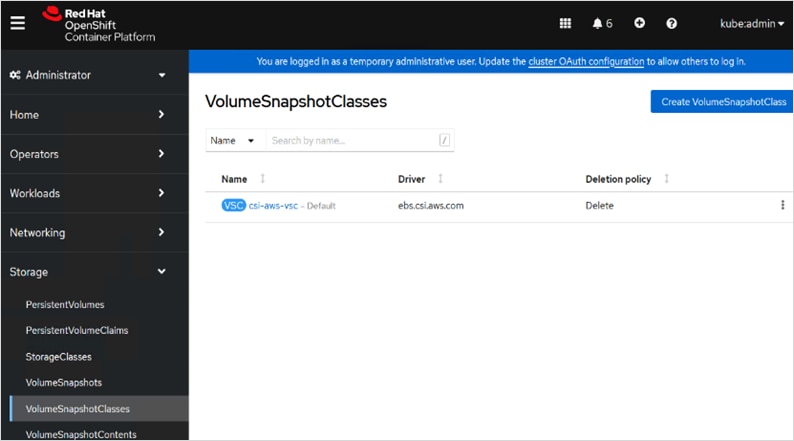
Step 4. Verify that there is a volume snapshot class defined. If not create one. The minimal configuration required is shown below. If there is one specified such as the case here, click the defined volume snapshot class and go to the YAML tab to verify that it has the same minimal information.
apiVersion: snapshot.storage.k8s.io/v1
deletionPolicy: Delete
driver: ebs.csi.aws.com
kind: VolumeSnapshotClass
metadata:
name: csi-aws-vsc
annotations:
k10.kasten.io/is-snapshot-class: 'true'
snapshot.storage.kubernetes.io/is-default-class: ‘true’
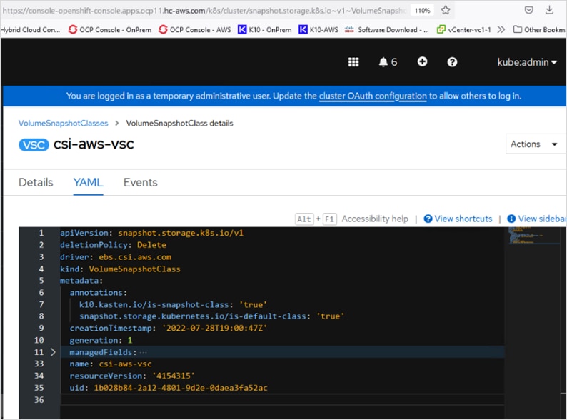
Enable Volume Snapshots using Kasten and AWS CSI (Public Cloud)
Use the steps outlined the Enable Volume Snapshots using Kasten and VMware vSphere CSI (On-Prem) section of this document to enable snapshots for the applications deployed on the OCP cluster in AWS.
Use Cases
This section will focus on two hybrid cloud use cases, namely Backup/Restore and Application Mobility from public cloud to on-prem.
Backup and Restore
Kasten K10 can be used in this solution to backup volume snapshots, application data, metadata, and other artifacts from both on-prem and public cloud locations in the hybrid deployment to an object store or NFS filesystem in a centralized location. The data can then be restored as needed based on the backup at each location, thereby providing resiliency and protection if the need occurs. The backup and restore is to the same location.
This section looks at how Kasten can be deployed to back up an application’s data and volume snapshots, and how it can be restored or recovered to the same location from a given restore point. To illustrate this use case, a sample application called pacman will be used. The application will be deployed in the app-pacman-staging namespace in the on-prem Red Hat OCP cluster running on HyperFlex VSI.
Procedure 1. Deploy sample application (pacman) on-prem
Step 1. Use the following commands to create the application on the on-prem OCP cluster.
oc new project app-pacman-staging
helm repo add veducate https://saintdle.github.io/helm-charts/
oc adm policy add-scc-to-user privileged -z default -n app-pacman-staging
helm install pacman veducate/pacman -n app-pacman-staging --set scc.create=true
kubectl expose deployment pacman --type=NodePort --name=pacman1
Step 2. Verify the application is up and running without any errors
oc get all <--- to verify that resources are up and running
oc get services <--- get Node Port info
oc get nodes <--- use the external IP of one of the nodes. This is any IP reachable from outside the cluster
curl http://<Node_IP>:<NodePort> <--- should return info with no errors
oc get pvc,pv,volumeattachments <--- additional verification of persistent volume claims to underlying storage
Step 3. Use a browser to navigate to http://<Node_IP>:<NodePort> and verify that pacman app is ready and running.
Procedure 2. Enable backup and export of application snapshots and data
Step 1. To automate the process of backing up application data at a regular interval, a policy must be defined. To create this policy, use a browser to navigate to the on-prem Kasten’s dashboard. Click anywhere within the Applications box. This will take you to a page with all the applications deployed on the cluster that you can now use to define policies and other actions per application.
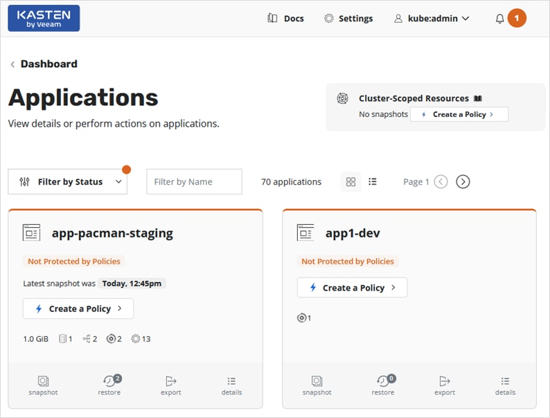
Step 2. Select the sample application pacman in the app-pacman-staging namespace. Click Create a Policy.
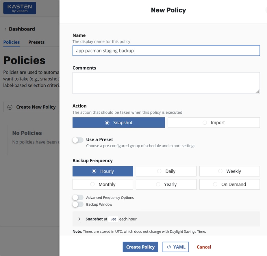
Step 3. In the New Policy window, scroll down and select Enable Backups via Snapshot Exports. Select an Export Frequency from the drop-down list and for the Export Location Profile, use the drop-down box to Create a new profile…
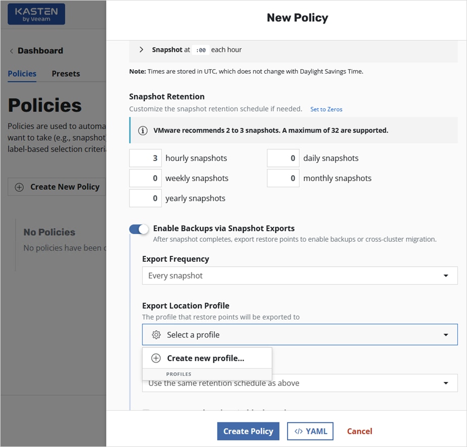
Step 4. In the New Profile pop-up window, specify a Profile Name. Select one of the public cloud options or a NFS FileStore or Veeam Repository to export the snapshot backups to. In this solution, Amazon S3 will be used. Specify AWS Access Key, Secret, Region, and Bucket name for the S3 bucket. Select other options as needed. Click Validate and Save button at the bottom of the window.
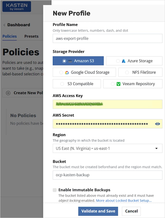
Step 5. If the information provided is correct, the profile will be created, and the newly created profile can be selected from the drop-down list as the Export Location Profile.
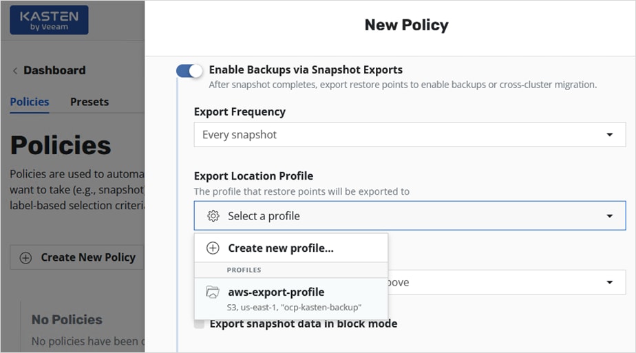
Step 6. Scroll down and enable Export snapshot data in block mode (supported with VMware vSphere CSI). For the Location Profile Supporting Block Mode, select the same profile as in the previous step from the drop-down menu.
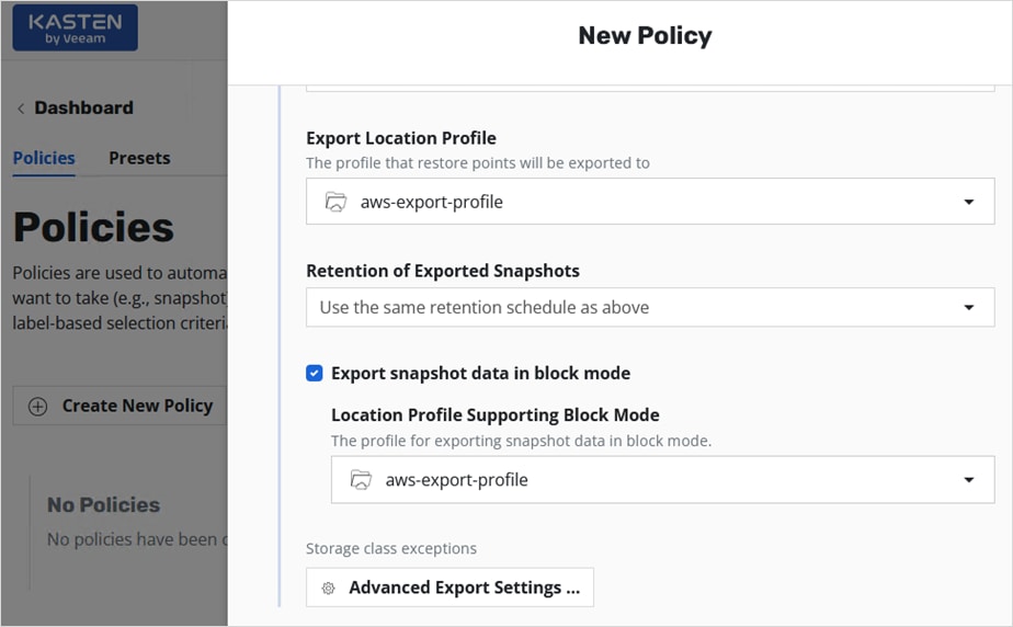
Step 7. Enable Snapshot Cluster-Scoped Resources. Leave everything else as default or adjust as needed. Click Create Policy button from the bottom of the window.
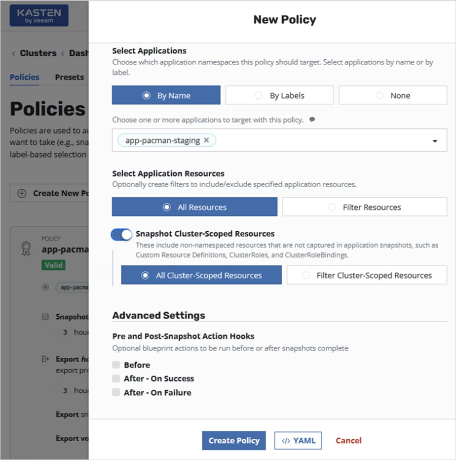
The policy should get created without errors with a Valid status if the information provided is accurate.
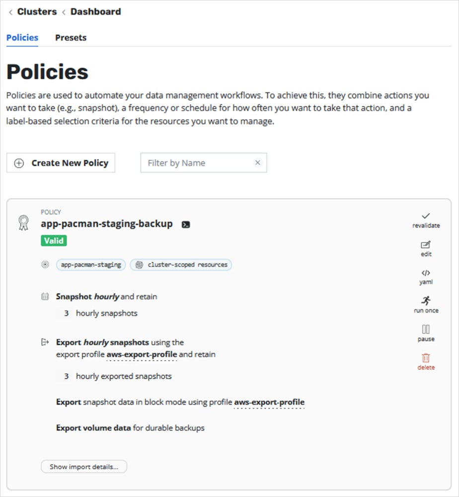
Step 8. To verify the policy, click run once from the right-side menu run the policy. Click Yes, Continue.
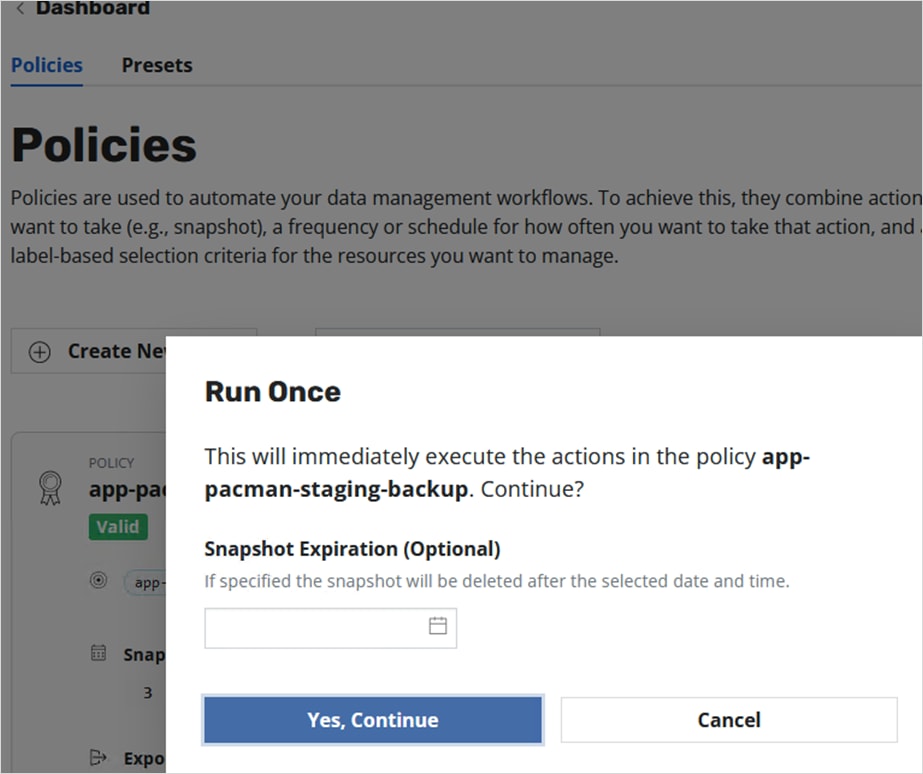
Step 9. Navigate back to the main Dashboard view and scroll down to the Actions section of the main dashboard to monitor the progress of backup policy.
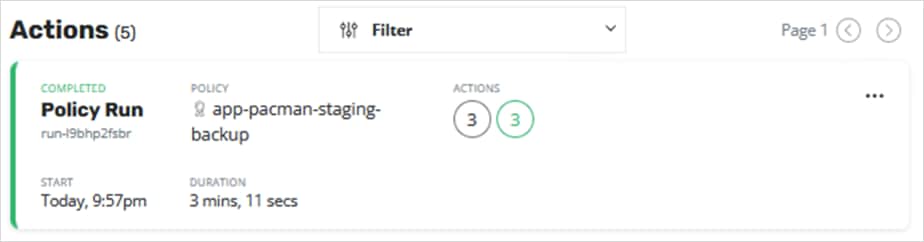
Step 10. Click the policy to get additional details and verify that the backup completed successfully.
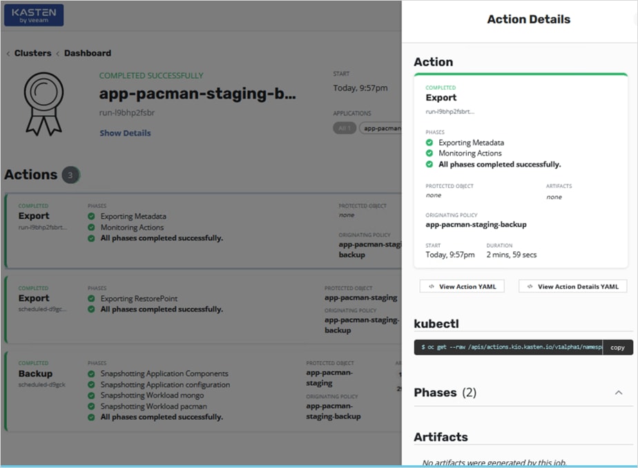
Procedure 1. Restore the application from the external export location to the on-prem cluster
Step 1. Navigate to on-prem Kasten’s dashboard. Click the Applications box and navigate to the app-pacman-staging namespace.
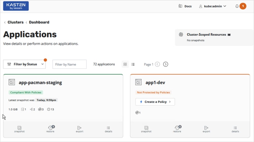
Step 2. Click Restore from the bottom menu in the app-pacman-staging box to view all the available restore points.
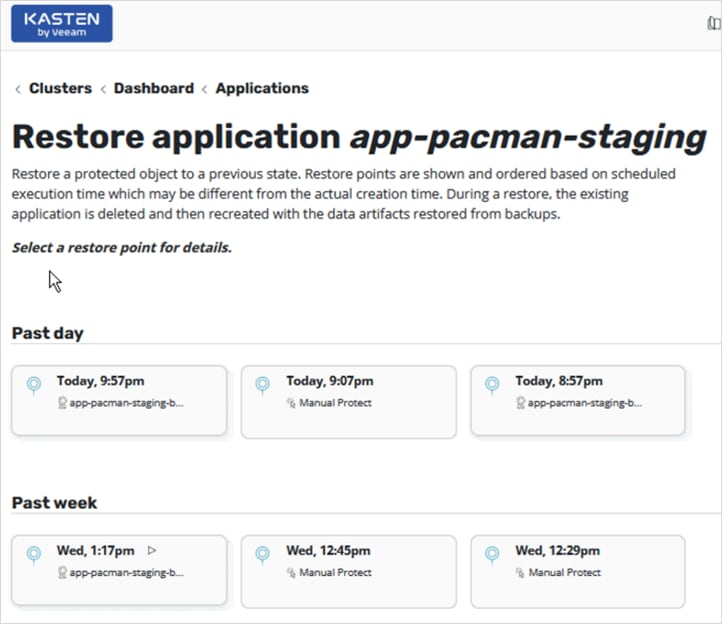
Step 3. Click one of the restore options to recover the application back to that restore point. Select either the local backup or the backup exported to the AWS S3 location.
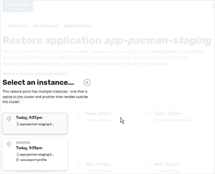
Step 4. Based on the selection, you can see additional details about the application and the restore point. You can restore to the same namespace or to a new one. By default, all artifacts are restored but you can choose to exclude some as needed. Click Restore.
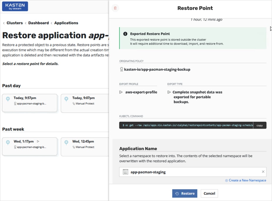
Step 5. Click Restore again in the Confirm Restore window.
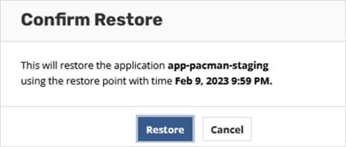
Step 6. Navigate back to the Actions section of the main dashboard to monitor the Restore and verify it completes successfully.
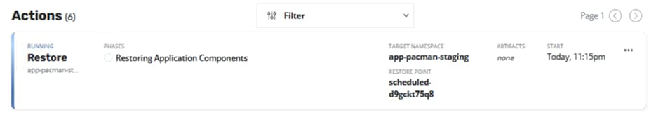
Dev/Test or Application Migration
As outlined previously in this document, Development/Test is a very common Hybrid Cloud use case where Enterprises may start their development and testing in the public cloud where they can quickly start the work without waiting for the infrastructure to be ready. However, once the development and testing is complete, they may need to bring the application workload back on-premise for staging and production. Kasten K10 provides an easy and convenient way to migrate an application developed in the public to be migrated back on-prem (or vice versa).
In this section, this use case uses a sample application (pacman) deployed in the app-pacman-dev namespace in the AWS OCP cloud and using AWS gp2 driver for persistent storage. Kasten K10 will then be used to migrate this application on-prem.
Procedure 1. Deploy sample application (pacman) in the Red Hat OCP cluster on AWS
Step 1. Use the following commands to create the application on the on-prem OCP cluster:
oc new project app-pacman-dev
helm repo add veducate https://saintdle.github.io/helm-charts/
oc adm policy add-scc-to-user privileged -z default -n app-pacman-dev
helm install pacman veducate/pacman -n app-pacman-dev --set scc.create=true
export SERVICE_IP=$(kubectl get svc --namespace app-pacman-dev pacman --template "{{ range (index .status.loadBalancer.ingress 0) }}{{.}}{{ end }}")
echo http://$SERVICE_IP:80
Step 2. Verify the application is up and running without any errors:
oc get all <--- to verify that resources are up and running
oc get services <--- get Node Port info
oc get nodes <--- use the external IP of one of the nodes. This is any IP reachable from outside the cluster
curl http://$SERVICE_IP:80 <--- should return info with no errors
oc get pvc,pv,volumeattachments <--- additional verification of persistent volume claims to underlying storage
Step 3. Use a browser to navigate to http://$SERVICE_IP:80 and verify that pacman app is ready and running.
Procedure 2. Enable backup and export of application snapshots and data
Step 1. Repeat the steps found here: Use Cases > Backup and Restore > Procedure 2 to setup a backup and export that backup to an external AWS S3 target.
Procedure 3. Migrate the application on-prem
Step 1. From the Kasten K10 dashboard running on the Red Hat OCP cluster in AWS, click the Applications box.
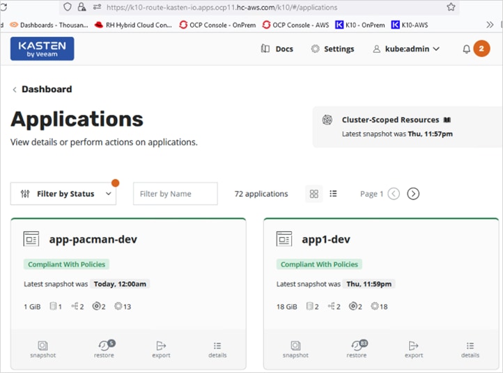
Step 2. Navigate to the sample application namespace (app-pacman-dev) box and click Export from the bottom menu.
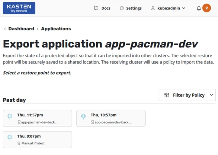
Step 3. Select a restore point to export. In the new Restore Point window, scroll down to Configure Export section and select a profile from the drop-down list. This will be the external location that the application and data is being backed up to.
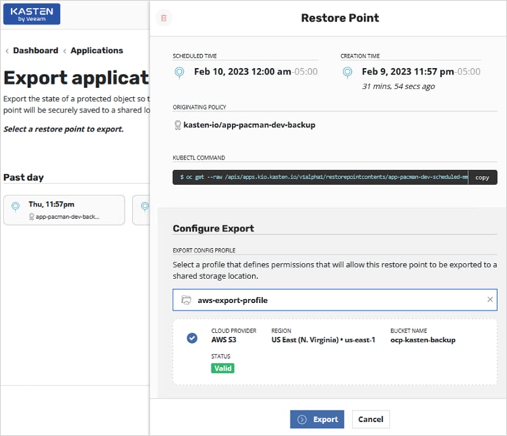
Step 4. Click Export button at the bottom of the window.
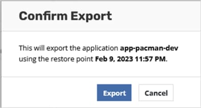
Step 5. Click Export again in the confirm Export pop-up window.
Step 6. In the Export Started Successfully pop-up window, click Copy to Clipboard to copy the encryption key that will be necessary to import this application onto the on-prem OCP cluster.
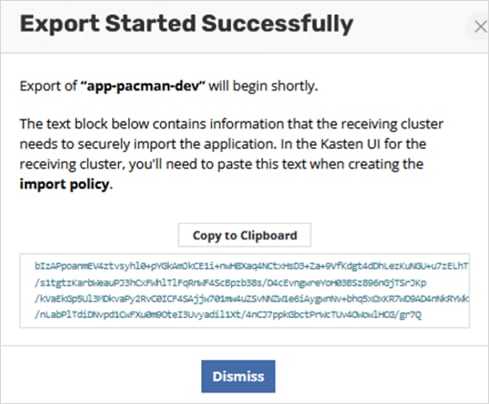
Step 7. Monitor the status of the export policy run in the Actions section of the Kasten dashboard.
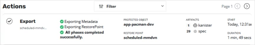
Step 8. Navigate to the on-prem Kasten dashboard to import the application to the one-prem OCP cluster.
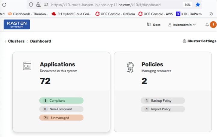
Step 9. Click the Policies box to create an import policy.
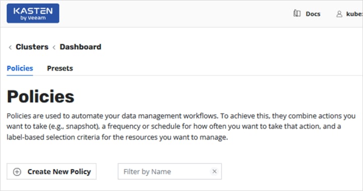
Step 10. Click the Create New Policy button. In the New Policy window, specify a Name for the import policy. Select the Import radio button. Select and enable Restore After Import.
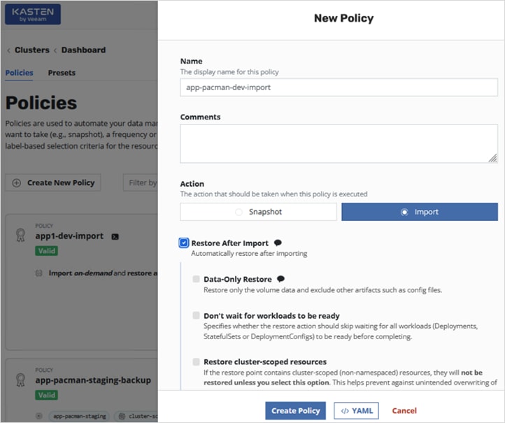
Step 11. Scroll down and select Apply transforms to restored resources to change the storage class to point to the vSphere CSI and HyperFlex storage.
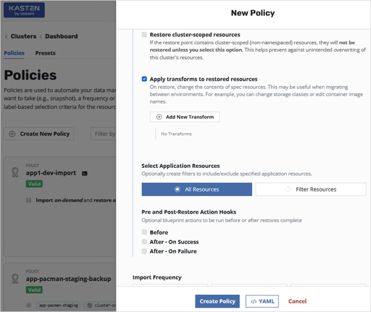
Step 12. Click Add New Transform. In the New Transform window, specify a Name. For the Resource, enter persistentvolumeclaim in the box.
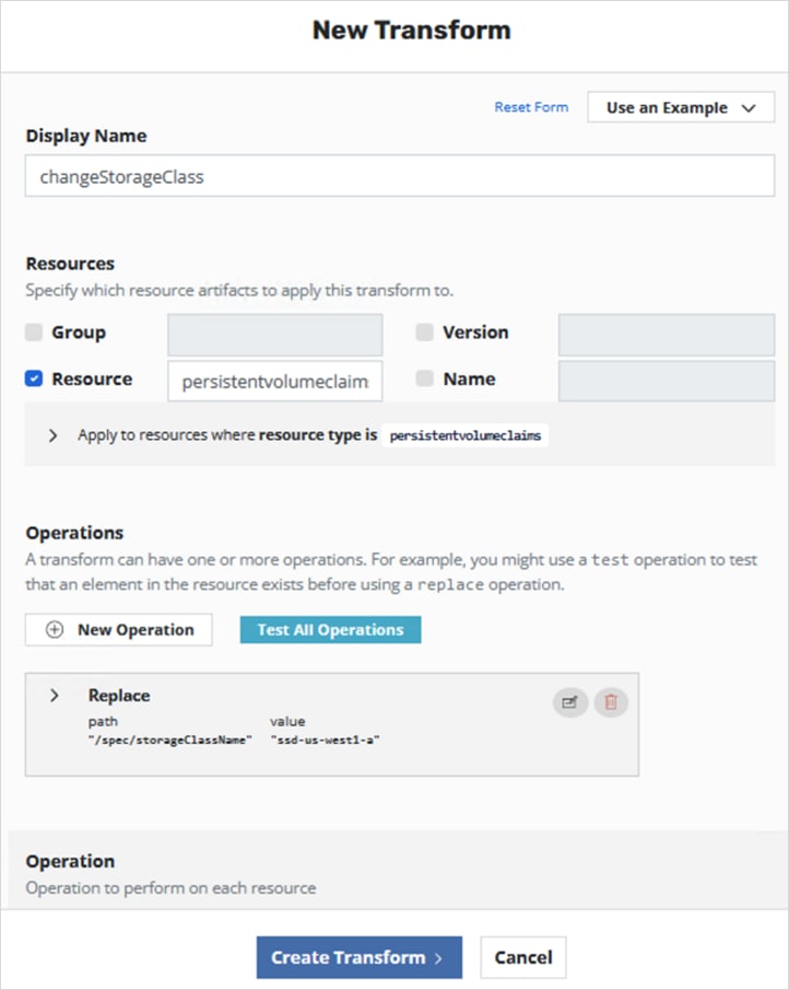
Step 13. Scroll down to the Operations section and click the Edit Operation icon in the Replace box.
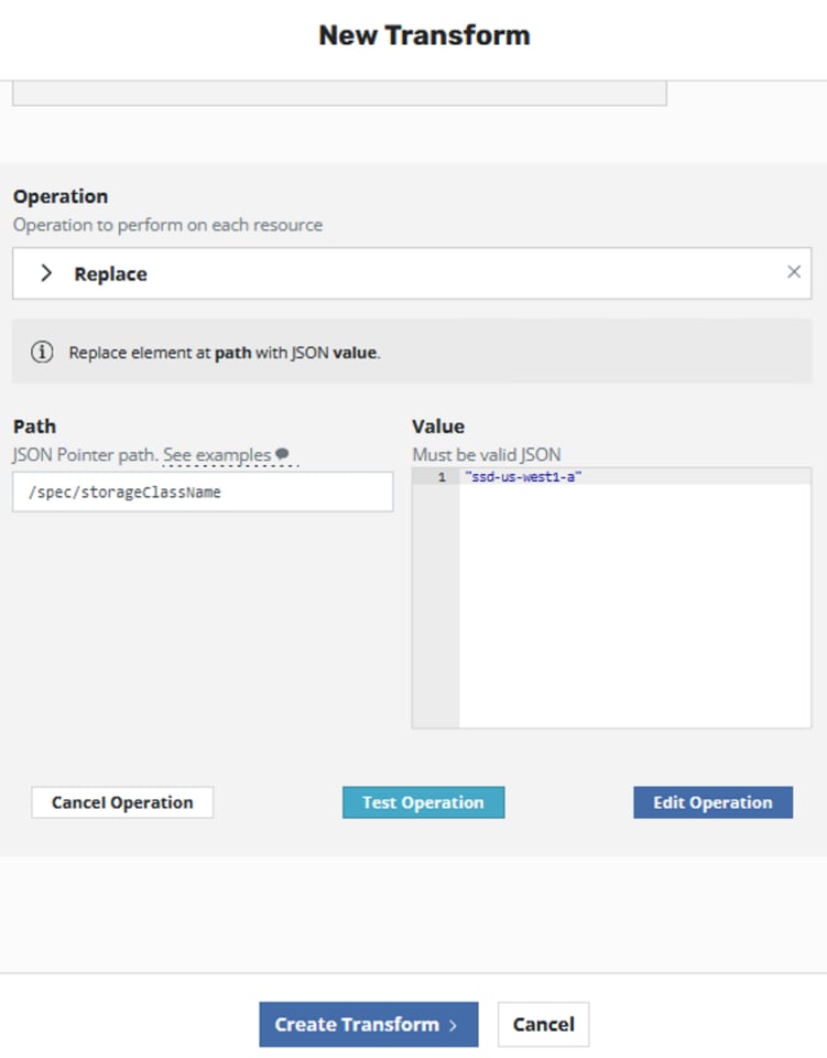
Step 14. Edit the Value box to reflect the storage class that should be used on-prem for this application.
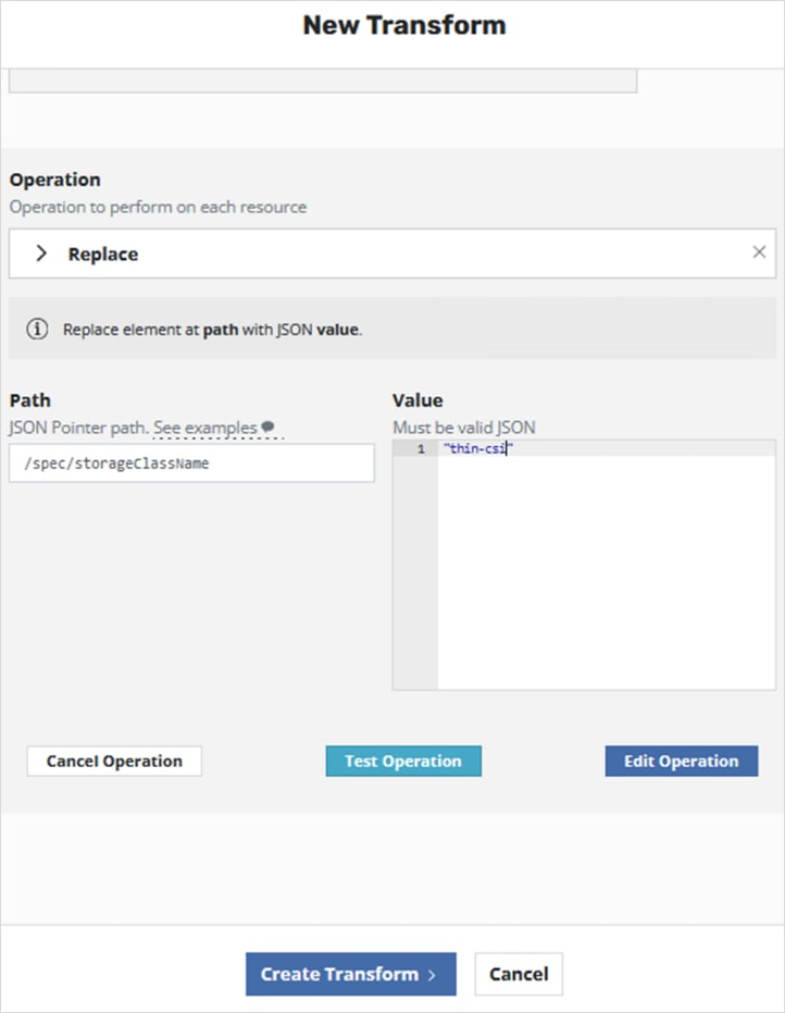
Step 15. Click Edit Operation.
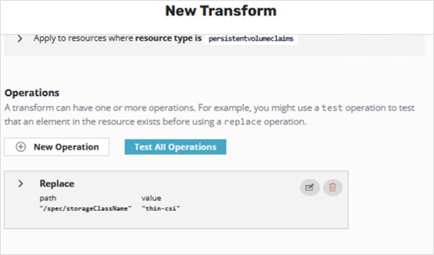
Step 16. Click Create Transform button to close the New Transform window with the transformation configuration complete.
Step 17. In the New Policy window, select the On Demand radio button.
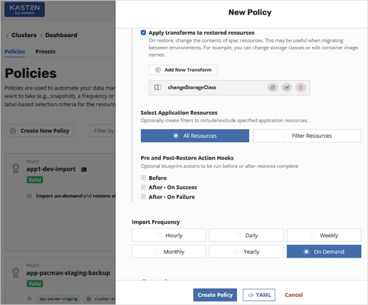
Step 18. Scroll down to the Config Data for Import section and paste the encryption key that was provided when the export policy was executed by Kasten to export the application from the AWS OCP cluster to on-prem. Select a Profile for Import from the drop-down list.
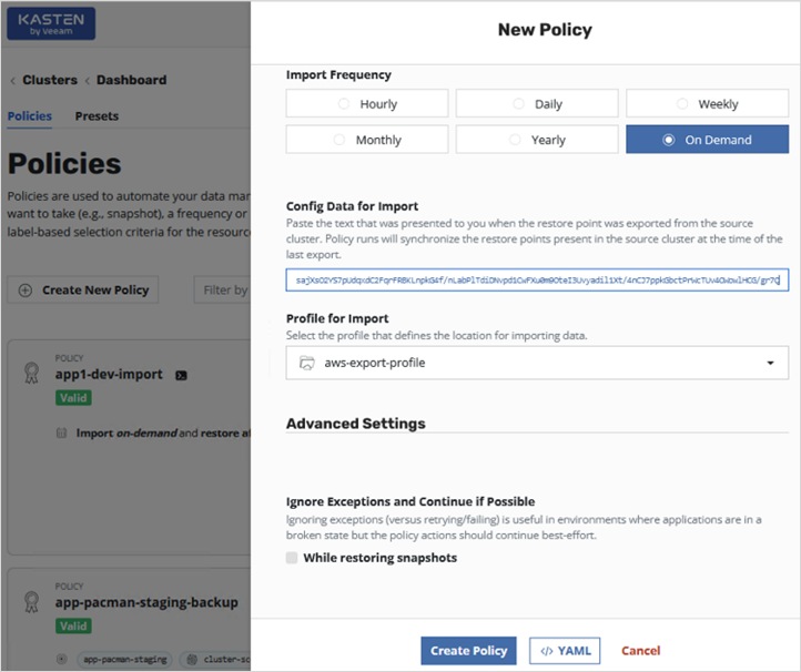
Step 19. Click Create Policy button at the bottom of the window to create a new import policy for migrating the application to on-prem OCP cluster.
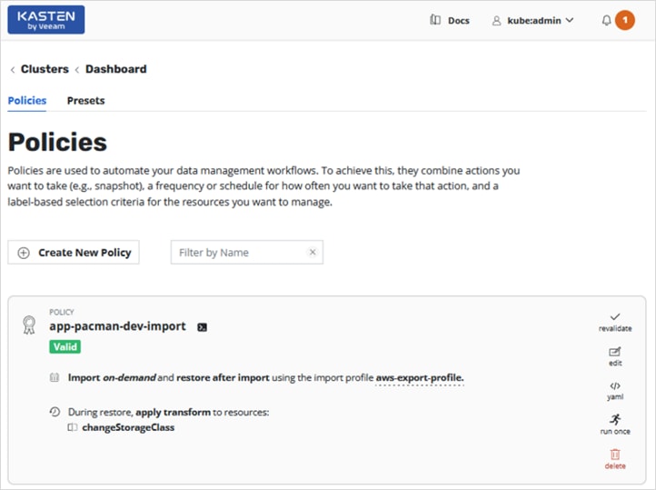
Step 20. Click run once icon in the policy to execute the policy and then monitor the execution from the Actions section of the on-prem Kasten dashboard.
Step 21. Verify that the import and restore completes successfully.
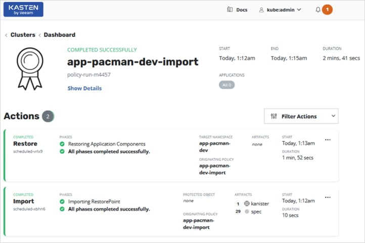
Step 22. The sample application (pacman) uses external Load balancer to access the application from outside the cluster. The on-prem cluster does not have a load balancer so NodePort will be used to expose the application outside the cluster. Execute the following commands against the on-prem OCP cluster to make the imported and restored pacman application accessible to users.
oc project app-pacman-dev
oc get all
kubectl expose deployment pacman --type=NodePort --name=pacman2
oc get all <-- get port info for NodePort
oc get nodes -o wide <-- select an external IP of one of the nodes
oc get nodes -o wide | awk -v OFS='\t\t' '{print $1, $6, $7}' <-- to get only the IPs
curl http://<Node_IP>:<NodePort>
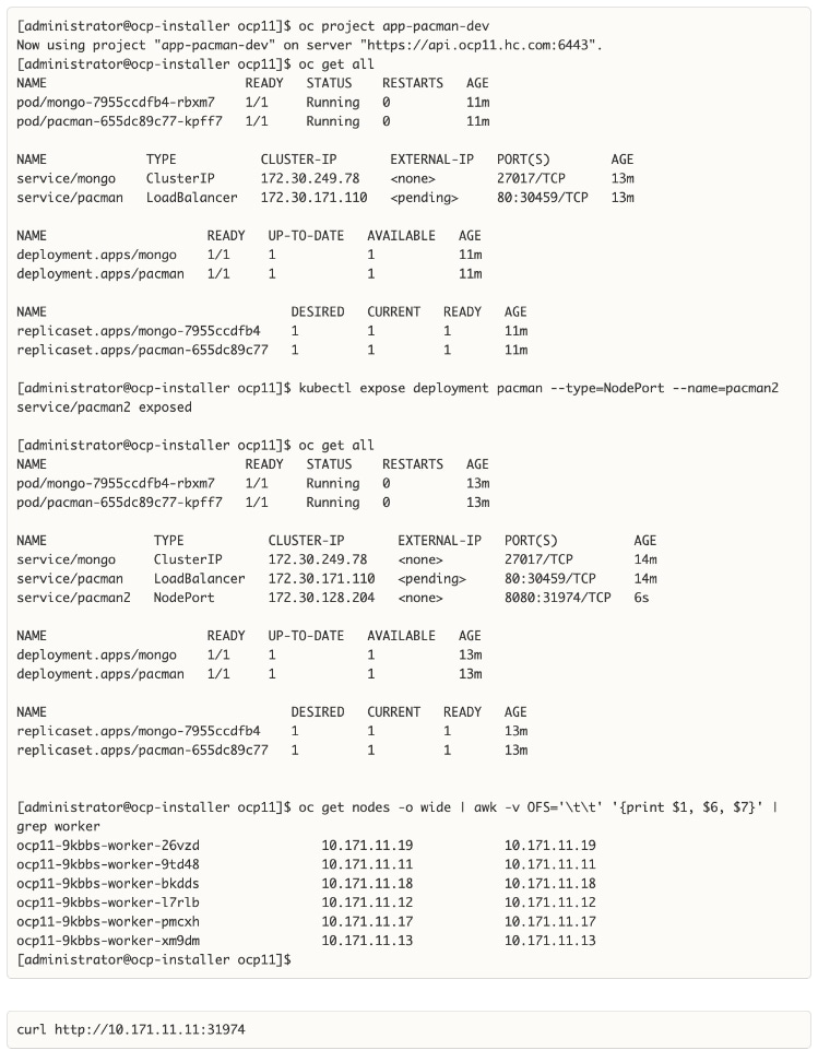
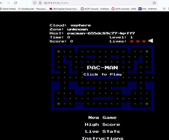
Step 23. Verify that the application is using on-prem storage class and storage that was specified in the transformation created in the policy.
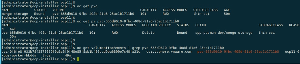
The original application running in the public cloud was successfully backed up and exported to external location, and then imported and restored on the on-prem OCP cluster running on HyperFlex VSI for compute and storage.
Enable Cisco Intersight Workload Optimizer (On-Prem)
This section describes the deployment of a resource optimization management tool for a cloud-native environment in an on-prem Enterprise data center. The solution uses Cisco Intersight Workload Optimizer (IWO), a service on Cisco Intersight, to ensure application performance and optimize resource usage.
The procedures outlined in this section will deploy Cisco IWO to monitor and optimize resource usage on a Red Hat OCP cluster running on an Application HyperFlex VSI cluster.
Prerequisites
● A valid cisco.com account to download IWO collector.
● OCP Installer or some other workstation to deploy the Cisco IWO collector. The workstation should be able to execute CLI commands on the Red Hat OCP cluster.
● Helm v2 (requires Tiller) or Helm v3 to install the collector in the OCP cluster.
● IWO collector Pods (two identical pods are deployed for high availability) require Kubelet access to every node in the cluster. Default: HTTPs + port=10250
● TCP port 80 and TCP/UDP port 443 must be open for collector to securely connect with Cisco Intersight
Setup Information
Table 17 lists the installation parameters for the IWO Collector.
Table 17. IWO Collector - Installation Parameters
| Variable |
Variable Name |
Value |
Additional Info |
| OCP Project or Namespace |
namespace |
iwo-collector |
|
| IWO Collector - name |
name |
iwo-collector-pod |
|
| IWO Collector Version |
iwoServerVersion |
8.5 |
|
| IWO Collector Image Tag |
collectoryImage.tag |
8.5.6 |
|
| IWO Name of Target cluster |
targetName |
ocp11-OnPrem.hc.com |
Doesn’t need to be same as OCP cluster name but it should be unique within IWO |
Deployment Steps
The procedures in this section will deploy Cisco IWO to monitor and optimize resource usage on a Red Hat OCP cluster running on an Application HyperFlex VSI cluster.
Procedure 1. Deploy Cisco IWO collector on the Red Hat OCP cluster
Step 1. Navigate using a web browser to Cisco Software Downloads page on cisco.com. Login using your Cisco account.
Step 2. In the Select a Product search area, enter Intersight.
Step 3. Select and click Intersight under Cloud and Systems Management.
Step 4. Select and click Intersight Kubernetes Collector.
Step 5. Download the latest Kubernetes Collector for Cisco Intersight Workload Optimizer to the on-prem OCP Installer (or any workstation that can execute CLI commands on the OCP cluster).
Step 6. From the OCP installer, verify you can access the cluster and create a separate Red Hat OCP project/namespace (iwo-collector) for IWO collector. Export kubeconfig if needed, for example: export KUBECONFIG=ocp11/auth/kubeconfig

Step 7. Extract the collector image downloaded from cisco.com. For example: tar -xvf iwo-k8s-collector-v1.2.0.tgz
Step 8. Do a dry-run of the collector install before deploying it. For Helm v3, execute the following command for a dry run:
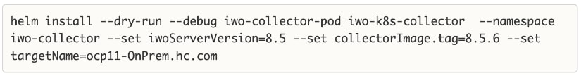
Step 9. Install the collector if the dry-run is successful. For Helm v3, execute the following command to install:
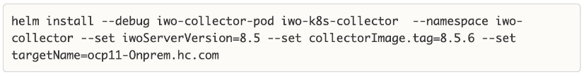
Step 10. Verify IWO collector Pods are up and running. Note one of the Pod names for use in the next step.
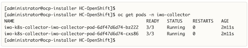
Step 11. Configure port forwarding as follows using one of the pods from the previous step.
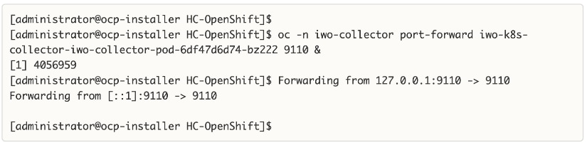
Step 12. Collect the Device ID using the following command: curl -s http://localhost:9110/DeviceIdentifiers
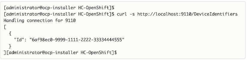
Step 13. Collect the Claim Code using the following command: curl -s http://localhost:9110/SecurityTokens
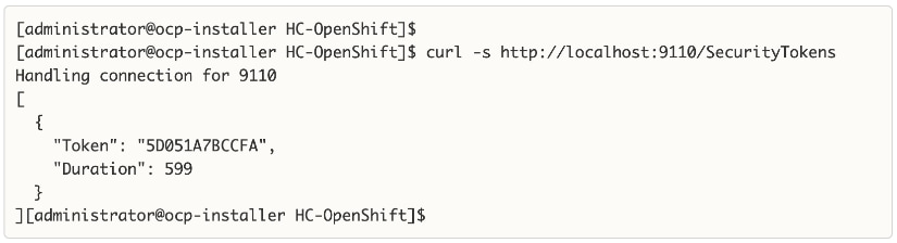
Procedure 2. Claim the on-prem IWO collector as a target in Cisco Intersight
Step 1. Navigate to intersight.com and login using your account.
Step 2. Select System from the drop-down list in the top left side of the window.
Step 3. Navigate to Targets and click Claim a New Target.
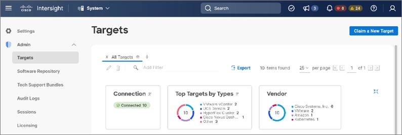
Step 4. In the Claim a New Target window, navigate to Filters and select Cloud Native. Select Kubernetes and click Start.
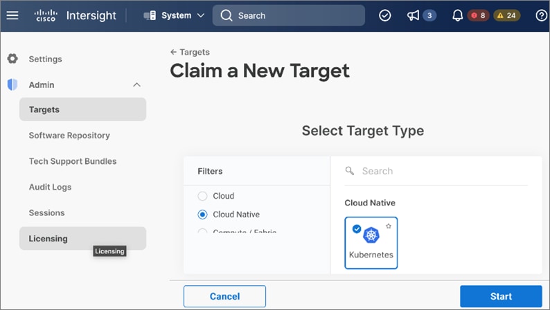
Step 5. Provide the Device ID and Claim Code collected from the IWO collector earlier.
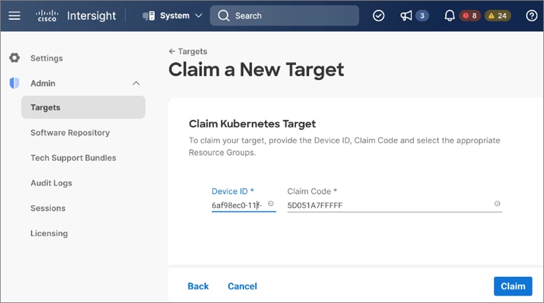
Step 6. Click Claim. Verify the on-prem collector for the OCP cluster is claimed in Cisco Intersight.
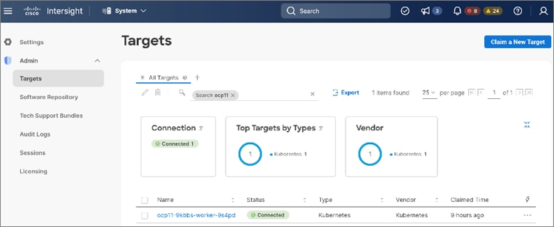
Procedure 3. Verify Cisco IWO is monitoring resources on the on-prem infrastructure
Step 1. From intersight.com, select Workload Optimizer from the drop-down list at the top left side of the window.
Step 2. Navigate to Overview and select the On-Prem tab from the right-side window.
Step 3. Verify that you are seeing everything from Container, Application and Service Components to underlying host, storage and other infrastructure in the dependency mapping created by IWO.
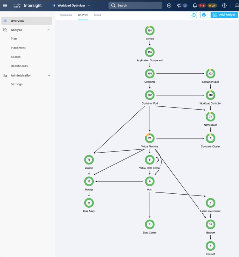
The Cisco IWO environment is now ready for use by the administrator to monitor and implement (manually or automated) policies to ensure application performance on the on-prem Red Hat OCP cluster.
Enable Cisco Intersight Workload Optimizer (Public Cloud)
This section describes the deployment of a resource optimization tool for managing cloud-native resources in AWS. The solution uses Cisco Intersight Workload Optimizer, a Cisco Intersight service, to ensure application performance and manage cloud costs.
The procedures outlined in this section will deploy Cisco Intersight Workload Optimizer on AWS EC2 instances hosting a Red Hat OCP cluster.
Prerequisites
● A valid cisco.com account to download IWO collector.
● OCP Installer in AWS or some other workstation to deploy the Cisco IWO collector. The workstation should be able to execute CLI commands on the Red Hat OCP cluster.
● Helm v2 (requires Tiller) or Helm v3 to install the collector in the OCP cluster.
● IWO collector Pods (two identical pods are deployed for high availability) require Kubelet access to every node in the OCP cluster. Default: HTTPs + port=10250
● Collector should be able to connect to Cisco Intersight through the Internet.
Setup Information
Table 18 lists the installation parameters for the IWO collector.
Table 18. IWO Collector - Installation Parameters
| Variable |
Variable Name |
Value |
Additional Info |
| OCP Project or Namespace |
namespace |
iwo-collector |
|
| IWO Collector - name |
name |
iwo-collector-pod |
|
| IWO Collector Version |
iwoServerVersion |
8.5 |
|
| IWO Collector Image Tag |
collectoryImage.tag |
8.5.6 |
|
| IWO Name of Target cluster |
targetName |
ocp11-AWS.hc.com |
Doesn’t need to be same as OCP cluster name but it should be unique within IWO |
Deployment Steps
The procedures in this section will deploy Cisco Intersight Workload Optimizer on AWS EC2 instances hosting a Red Hat OCP cluster.
Procedure 1. Deploy Cisco IWO collector on Red Hat OCP cluster
Step 1. Follow the procedure here, in the on-prem Cisco IWO Deployment section to deploy the collector in AWS OCP cluster using the AWS setup information provided earlier.
Procedure 2. Claim Cisco IWO collector as a target in Intersight
Step 1. Follow the procedure here, in the on-prem Cisco IWO Deployment section to claim the collector as a target in Cisco Intersight.
Procedure 3. Verify Cisco IWO is monitoring resources in AWS
Step 1. From intersight.com, select Workload Optimizer from the drop-down list at the top left side of the window.
Step 2. Navigate to Overview and select the Cloud tab from the right-side window.
Step 3. Verify that you are seeing the Container, Application and Service Components and the underlying AWS resources in the dependency mapping created by IWO.
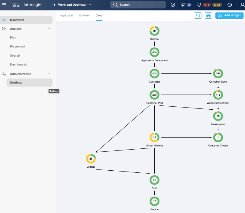
The Cisco IWO environment is now ready for use by the administrator to monitor and implement (manually or automated) policies to ensure application performance on the Red Hat OCP cluster in AWS.
Hybrid cloud is the de facto operating model in most Enterprises today. Cisco HyperFlex with Red Hat OCP solution provides a flexible foundational hybrid cloud architecture that Enterprises can adopt and standardize on from enterprise edge to core data centers. The solution offers an enterprise-grade Kubernetes environment for an Enterprise’s cloud native efforts platform with Enterprise-level support from Cisco and Red Hat. Cisco HyperFlex is an essential building block that provides the fastest path to hybrid cloud with enterprise-grade, software-defined compute, and storage infrastructure. Coupled with Cisco Intersight, HyperFlex can be deployed and managed with simplicity and ease across all Enterprise locations, around the globe. Cisco Intersight can deliver a production-ready Virtual Server Infrastructure (VSI) in less than an hour using a fully automated deployment process.
The SaaS model enables you to install, deploy, monitor, and maintain all of your clusters wherever they reside from a central portal. Intersight offers a comprehensive set of day-2 management capabilities that greatly simplifies and accelerates operations. It includes features such as cluster expansion, full-stack upgrades, day-2 storage management with performance monitoring, connected TAC support, hardware compatibility checks and tools for capacity planning and cluster health checks. Red Hat OpenShift Container Platform provides an enterprise-grade Kubernetes platform with consistent management and development experience across a hybrid environment for both operations and development teams. Cisco Intersight Workload Optimizer, a service in Cisco Intersight, can continuously monitor and optimizes resources across the stack to lower cloud costs and ensure application performance across hybrid cloud environment. While Kubernetes eliminates the pain of ensuring high availability and scalability of application services, these benefits do not extend to data. Kasten K10 is a Cloud Native data management platform that overcomes such Day 2 challenges by providing enterprise DevOps teams with backup/restore, disaster recovery and application mobility for Kubernetes applications.
Archana Sharma, Technical Leader, Cisco UCS Data Center Solutions, Cisco Systems Inc.
Archana Sharma is Technical Marketing Engineer with over 20 years of experience at Cisco on a range of technologies that span Data Center, Desktop Virtualization, Collaboration, and other Layer2 and Layer3 technologies. Archana is focused on systems and solutions for Enterprise and Provider deployments, including delivery of Cisco Validated designs for over 10 years. Archana is currently working on designing and integrating Cisco UCS-based Converged Infrastructure solutions. Archana holds a CCIE (#3080) in Routing and Switching and a bachelor’s degree in Electrical Engineering from North Carolina State University.
This appendix is organized into the following sections:
● Appendix A – On-Prem Site-to-Site VPN Configuration
● Appendix B – References Used in Guide
● Appendix E – Recommended for You
Appendix A – On-Prem Site-to-Site VPN Configuration
Customer Gateway – 1 (On-Prem)
HC-RTP-Site1-CSR1kv-1#show run
Building configuration...
Current configuration : 12630 bytes
!
! Last configuration change at 21:06:20 UTC Thu Jul 28 2022 by admin
!
version 17.3
service timestamps debug datetime msec
service timestamps log datetime msec
service call-home
platform qfp utilization monitor load 80
platform punt-keepalive disable-kernel-core
platform console virtual
platform hardware throughput level MB 5000
!
hostname HC-RTP-Site1-CSR1kv-1
!
boot-start-marker
boot-end-marker
!
enable secret 9 $9$85NtD8GXl77uIk$BNe35miWi7qFO72Nb0mknPjZBMJVng/h.jQlIt4ug6g
!
no aaa new-model
!
ip domain lookup source-interface GigabitEthernet1
ip domain name cspg.local
!
login on-success log
!
subscriber templating
!
multilink bundle-name authenticated
!
crypto pki trustpoint TP-self-signed-2015064199
enrollment selfsigned
subject-name cn=IOS-Self-Signed-Certificate-2015064199
revocation-check none
rsakeypair TP-self-signed-2015064199
!
crypto pki trustpoint SLA-TrustPoint
enrollment terminal
revocation-check crl
!
crypto pki certificate chain TP-self-signed-2015064199
certificate self-signed 01
<!! REMOVED !!>
quit
crypto pki certificate chain SLA-TrustPoint
certificate ca 01
<!! REMOVED !!>
quit
!
crypto pki certificate pool
cabundle nvram:ios_core.p7b
!
license udi pid CSR1000V sn 9CCCQFFFGV
license boot level ax
diagnostic bootup level minimal
memory free low-watermark processor 71489
!
spanning-tree extend system-id
!
username admin privilege 15 secret 9 $9$g8936Xyf7Fy64E$QdjuY/IIN6RXBRvc40NMLc6Bd5uXP36LhdalczF4Y4g
!
redundancy
!
crypto ikev2 proposal PROPOSAL1
encryption aes-cbc-128 aes-cbc-192 aes-cbc-256
integrity sha1 sha512 sha384 sha256
group 24 21 20 19 16 15 14 2
!
crypto ikev2 policy POLICY1
match address local 192.168.171.251
proposal PROPOSAL1
!
crypto ikev2 keyring KEYRING1
peer 18.233.149.22
address 18.233.149.22
pre-shared-key DPd4oIk8bflTRRqZXh6xjShL8.AyLfwr
!
!
crypto ikev2 keyring KEYRING2
peer 34.199.172.92
address 34.199.172.92
pre-shared-key T3XV4of7JGljGRmiCZMLdMyrq.uwNm8L
!
crypto ikev2 profile IKEV2-PROFILE-1
match address local 192.168.171.251
match identity remote address 18.233.149.22 255.255.255.255
identity local address 64.100.255.181
authentication remote pre-share
authentication local pre-share
keyring local KEYRING1
lifetime 28800
dpd 10 10 on-demand
!
crypto ikev2 profile IKEV2-PROFILE-2
match address local 192.168.171.251
match identity remote address 34.199.172.92 255.255.255.255
identity local address 64.100.255.181
authentication remote pre-share
authentication local pre-share
keyring local KEYRING2
lifetime 28800
dpd 10 10 on-demand
!
lldp run
cdp run
!
crypto isakmp keepalive 10 10
!
crypto ipsec security-association replay window-size 128
!
crypto ipsec transform-set ipsec-prop-vpn-0688beafa0fc10988-0 esp-aes esp-sha256-hmac
mode tunnel
crypto ipsec transform-set ipsec-prop-vpn-0688beafa0fc10988-1 esp-aes esp-sha256-hmac
mode tunnel
crypto ipsec df-bit clear
!
crypto ipsec profile ipsec-vpn-0688beafa0fc10988-0
set transform-set ipsec-prop-vpn-0688beafa0fc10988-0
set pfs group14
set ikev2-profile IKEV2-PROFILE-1
!
crypto ipsec profile ipsec-vpn-0688beafa0fc10988-1
set transform-set ipsec-prop-vpn-0688beafa0fc10988-1
set pfs group14
set ikev2-profile IKEV2-PROFILE-2
!
interface Loopback0
description TEST-AWS-INTERFACE
ip address 51.51.51.251 255.255.255.0
!
interface Tunnel1
description Tunnel#1 to AWS-TGW
ip address 169.254.109.206 255.255.255.252
ip tcp adjust-mss 1379
tunnel source GigabitEthernet2
tunnel mode ipsec ipv4
tunnel destination 18.233.149.22
tunnel protection ipsec profile ipsec-vpn-0688beafa0fc10988-0
ip virtual-reassembly
!
interface Tunnel2
description Tunnel#2 to AWS-TGW
ip address 169.254.229.110 255.255.255.252
ip tcp adjust-mss 1379
tunnel source GigabitEthernet2
tunnel mode ipsec ipv4
tunnel destination 34.199.172.92
tunnel protection ipsec profile ipsec-vpn-0688beafa0fc10988-1
ip virtual-reassembly
!
interface GigabitEthernet1
description OOB Mgmt
ip address 172.26.163.251 255.255.255.0
negotiation auto
no mop enabled
no mop sysid
!
interface GigabitEthernet2
description To On-Prem Networks and source IPsec interface to AWS
ip address 192.168.171.251 255.255.255.0
negotiation auto
no mop enabled
no mop sysid
!
ip forward-protocol nd
ip http server
ip http authentication local
ip http secure-server
ip http client source-interface GigabitEthernet1
!
ip route 0.0.0.0 0.0.0.0 172.26.163.254
ip route 10.0.0.0 255.255.0.0 Tunnel1
ip route 10.0.0.0 255.255.0.0 Tunnel2
ip route 18.233.149.22 255.255.255.255 GigabitEthernet2 192.168.171.254
ip route 34.199.172.92 255.255.255.255 GigabitEthernet2 192.168.171.254
ip route 64.100.255.189 255.255.255.255 GigabitEthernet2 192.168.171.254
ip route 172.26.163.0 255.255.255.0 GigabitEthernet1 172.26.163.254
ip route 172.31.0.0 255.255.0.0 Tunnel1
ip route 172.31.0.0 255.255.0.0 Tunnel2
ip ssh rsa keypair-name ssh-key
ip ssh version 2
ip scp server enable
!
control-plane
!
line con 0
exec-timeout 90 0
stopbits 1
line vty 0 4
exec-timeout 90 0
login local
transport input ssh
!
call-home
! If contact email address in call-home is configured as sch-smart-licensing@cisco.com
! the email address configured in Cisco Smart License Portal will be used as contact
! email address to send SCH notifications.
contact-email-addr sch-smart-licensing@cisco.com
profile "CiscoTAC-1"
active
destination transport-method http
!
end
HC-RTP-Site1-CSR1kv-1#
Customer Gateway – 2 (On-Prem)
HC-RTP-Site1-CSR1kv-2#show run
Building configuration...
Current configuration : 11938 bytes
!
! Last configuration change at 15:11:46 UTC Mon Jul 28 2022 by admin
!
version 17.3
service timestamps debug datetime msec
service timestamps log datetime msec
service call-home
platform qfp utilization monitor load 80
platform punt-keepalive disable-kernel-core
platform console virtual
platform hardware throughput level MB 5000
!
hostname HC-RTP-Site1-CSR1kv-2
!
boot-start-marker
boot-end-marker
!
enable secret 9 $9$Y8hVg5t/EgKMK.$NhS1soDgDKK4u5.ExrGUYI3hcPlceUYVBCoL7MYhCgM
!
no aaa new-model
!
ip domain lookup source-interface GigabitEthernet1
ip domain name cspg.local
!
login on-success log
!
subscriber templating
!
multilink bundle-name authenticated
!
crypto pki trustpoint TP-self-signed-1201348278
enrollment selfsigned
subject-name cn=IOS-Self-Signed-Certificate-1201348278
revocation-check none
rsakeypair TP-self-signed-1201348278
!
crypto pki trustpoint SLA-TrustPoint
enrollment terminal
revocation-check crl
!
crypto pki certificate chain TP-self-signed-1201348278
certificate self-signed 01
<!! REMOVED !!>
quit
crypto pki certificate chain SLA-TrustPoint
certificate ca 01
<!! REMOVED !!>
quit
!
crypto pki certificate pool
cabundle nvram:ios_core.p7b
!
license udi pid CSR1000V sn 9Q28ZTVBYYH
license boot level ax
diagnostic bootup level minimal
memory free low-watermark processor 71489
!
spanning-tree extend system-id
!
username admin privilege 15 secret 9 $9$5gt0bisfQriQVk$VDkvYrDTRJE2QkIJ0ci5vo5dfV2P561XjSI1wf4eX2A
!
redundancy
!
crypto ikev2 proposal PROPOSAL1
encryption aes-cbc-128 aes-cbc-192 aes-cbc-256
integrity sha1 sha512 sha384 sha256
group 24 21 20 19 16 15 14 2
crypto ikev2 proposal ikev2-proposal-default
encryption aes-cbc-256 aes-cbc-192 aes-cbc-128
integrity sha512 sha384 sha256 sha1
group 24 21 20 19 16 15 14 2
!
crypto ikev2 policy POLICY1
match address local 192.168.171.252
proposal PROPOSAL1
crypto ikev2 policy ikev2-policy-default
proposal ikev2-proposal-default
!
crypto ikev2 keyring KEYRING1
peer 18.210.98.60
address 18.210.98.60
pre-shared-key x_X0D_MOOrTSHQK.p84TNKmgQdv2PkxP
!
crypto ikev2 keyring KEYRING2
peer 34.204.64.189
address 34.204.64.189
pre-shared-key sCpDlVSrqWHqSnZHUENYL5JWapQS0sJd
!
crypto ikev2 profile IKEV2-PROFILE-1
match address local 192.168.171.252
match identity remote address 18.210.98.60 255.255.255.255
identity local address 64.100.255.182
authentication remote pre-share
authentication local pre-share
keyring local KEYRING1
lifetime 28800
dpd 10 10 on-demand
!
crypto ikev2 profile IKEV2-PROFILE-2
match address local 192.168.171.252
match identity remote address 34.204.64.189 255.255.255.255
identity local address 64.100.255.182
authentication remote pre-share
authentication local pre-share
keyring local KEYRING2
lifetime 28800
dpd 10 10 on-demand
!
lldp run
cdp run
!
crypto isakmp keepalive 10 10
!
crypto ipsec security-association replay window-size 128
!
crypto ipsec transform-set ipsec-prop-vpn-02363cbefd8b34ee8-0 esp-aes esp-sha256-hmac
mode tunnel
crypto ipsec transform-set ipsec-prop-vpn-02363cbefd8b34ee8-1 esp-aes esp-sha256-hmac
mode tunnel
crypto ipsec df-bit clear
!
crypto ipsec profile ipsec-vpn-02363cbefd8b34ee8-0
set transform-set ipsec-prop-vpn-02363cbefd8b34ee8-0
set pfs group14
set ikev2-profile IKEV2-PROFILE-1
!
crypto ipsec profile ipsec-vpn-02363cbefd8b34ee8-1
set transform-set ipsec-prop-vpn-02363cbefd8b34ee8-1
set pfs group14
set ikev2-profile IKEV2-PROFILE-2
!
interface Loopback0
description TEST-AWS-INTERFACE
ip address 51.51.51.251 255.255.255.0
!
interface Tunnel1
ip address 169.254.44.110 255.255.255.252
ip tcp adjust-mss 1379
tunnel source GigabitEthernet2
tunnel mode ipsec ipv4
tunnel destination 18.210.98.60
tunnel protection ipsec profile ipsec-vpn-02363cbefd8b34ee8-0
ip virtual-reassembly
!
interface Tunnel2
ip address 169.254.104.218 255.255.255.252
ip tcp adjust-mss 1379
tunnel source GigabitEthernet2
tunnel mode ipsec ipv4
tunnel destination 34.204.64.189
tunnel protection ipsec profile ipsec-vpn-02363cbefd8b34ee8-1
ip virtual-reassembly
!
interface GigabitEthernet1
description OOB Mgmt
ip address 172.26.163.252 255.255.255.0
negotiation auto
no mop enabled
no mop sysid
!
interface GigabitEthernet2
description To On-Prem Networks and source IPsec interface to AWS
ip address 192.168.171.252 255.255.255.0
negotiation auto
no mop enabled
no mop sysid
!
ip forward-protocol nd
ip http server
ip http authentication local
ip http secure-server
ip http client source-interface GigabitEthernet1
!
ip route 0.0.0.0 0.0.0.0 172.26.163.254
ip route 10.0.0.0 255.255.255.0 Tunnel1
ip route 10.0.0.0 255.255.255.0 Tunnel2
ip route 18.210.98.60 255.255.255.255 GigabitEthernet2 192.168.171.254
ip route 34.204.64.189 255.255.255.255 GigabitEthernet2 192.168.171.254
ip route 64.100.255.189 255.255.255.255 GigabitEthernet2 192.168.171.254
ip route 172.26.163.0 255.255.255.0 GigabitEthernet1 172.26.163.254
ip ssh rsa keypair-name ssh-key
ip ssh version 2
ip scp server enable
!
control-plane
!
line con 0
exec-timeout 90 0
stopbits 1
line vty 0 4
exec-timeout 90 0
login local
transport input ssh
!
call-home
! If contact email address in call-home is configured as sch-smart-licensing@cisco.com
! the email address configured in Cisco Smart License Portal will be used as contact email address to send SCH notifications.
contact-email-addr sch-smart-licensing@cisco.com
profile "CiscoTAC-1"
active
destination transport-method http
!
end
HC-RTP-Site1-CSR1kv-2#
Appendix B – References Used in Guide
26 Kubernetes Statistics to Reference:
https://www.containiq.com/post/kubernetes-statistics
Red Hat OpenShift vs. Kubernetes:
https://www.redhat.com/en/topics/containers/red-hat-openshift-kubernetes
Cisco HyperFlex Data Sheets:
https://www.cisco.com/c/en/us/products/hyperconverged-infrastructure/hyperflex-hx-series/datasheet-listing.html
Cisco Intersight:
https://www.cisco.com/c/en/us/products/servers-unified-computing/intersight/index.html
Cisco Unified Computing System:
http://www.cisco.com/en/US/products/ps10265/index.html
Cisco UCS Manager:
http://www.cisco.com/en/US/products/ps10281/index.html
Red Hat OpenShift:
https://www.openshift.com/
Red Hat Hybrid Cloud Console:
https://access.redhat.com/products/red-hat-hybrid-cloud-console
Red Hat Ansible:
https://www.ansible.com/resources/get-started
Cisco IWO User Guide: https://www.cisco.com/c/dam/en/us/td/docs/unified_computing/ucs/Intersight/Intersight_Workload_Optimizer/Cisco_Intersight_Workload_Optimizer_User_Guide.pdf
Cisco IWO Data Sheet:
https://www.cisco.com/c/en/us/products/collateral/cloud-systems-management/intersight-workload-optimizer/datasheet-c78-744509.html
Cisco IWO Documentation:
https://intersight.com/help/resources#cisco_intersight_workload_optimizer
VMware vSphere CSI Plug-in:
https://docs.vmware.com/en/VMware-vSphere-Container-Storage-Plug-in/index.html
VMware vSphere CSI Driver Operator – Red Hat
https://docs.openshift.com/container-platform/4.10/storage/container_storage_interface/persistent-storage-csi-vsphere.html
This glossary addresses some terms used in this document, for the purposes of aiding understanding. This is not a complete list of all multicloud terminology. Some Cisco product links are supplied here also, where considered useful for the purposes of clarity, but this is by no means intended to be a complete list of all applicable Cisco products.
| aaS/XaaS (IT capability provided as a Service) |
Some IT capability, X, provided as a service (XaaS). Some benefits are:
● The provider manages the design, implementation, deployment, upgrades, resiliency, scalability, and overall delivery of the service and the infrastructure that supports it.
● There are very low barriers to entry, so that services can be quickly adopted and dropped in response to business demand, without the penalty of inefficiently utilized CapEx.
● The service charge is an IT OpEx cost (pay-as-you-go), whereas the CapEx and the service infrastructure is the responsibility of the provider.
● Costs are commensurate to usage and hence more easily controlled with respect to business demand and outcomes.
Such services are typically implemented as “microservices,” which are accessed via REST APIs. This architectural style supports composition of service components into systems. Access to and management of aaS assets is via a web GUI and/or APIs, such that Infrastructure-as-code (IaC) techniques can be used for automation, for example, Ansible and Terraform. The provider can be any entity capable of implementing an aaS “cloud-native” architecture. The cloud-native architecture concept is well-documented and supported by open-source software and a rich ecosystem of services such as training and consultancy. The provider can be an internal IT department or any of many third-party companies using and supporting the same open-source platforms. Service access control, integrated with corporate IAM, can be mapped to specific users and business activities, enabling consistent policy controls across services, wherever they are delivered from. |
| Ansible |
An infrastructure automation tool, used to implement processes for instantiating and configuring IT service components, such as VMs on an IaaS platform. Supports the consistent execution of processes defined in YAML “playbooks” at scale, across multiple targets. Because the Ansible artefacts (playbooks) are text-based, they can be stored in a Source Code Management (SCM) system, such as GitHub. This allows for software development like processes to be applied to infrastructure automation, such as, Infrastructure-as-code (see IaC below). |
| AWS (Amazon Web Services) |
Provider of IaaS and PaaS. |
| Azure |
Microsoft IaaS and PaaS. |
| Co-located data center |
“A colocation center (CoLo)…is a type of data center where equipment, space, and bandwidth are available for rental to retail customers. Colocation facilities provide space, power, cooling, and physical security for the server, storage, and networking equipment of other firms and also connect them to a variety of telecommunications and network service providers with a minimum of cost and complexity.” |
| Containers (Docker) |
A (Docker) container is a means to create a package of code for an application and its dependencies, such that the application can run on different platforms which support the Docker environment. In the context of aaS, microservices are typically packaged within Linux containers orchestrated by Kubernetes (K8s). https://www.cisco.com/c/en/us/products/cloud-systems-management/containerplatform/index.html |
| DevOps |
The underlying principle of DevOps is that the application development and operations teams should work closely together, ideally within the context of a toolchain that automates the stages of development, test, deployment, monitoring, and issue handling. DevOps is closely aligned with IaC, continuous integration and deployment (CI/CD), and Agile software development practices. |
| Edge compute |
Edge compute is the idea that it can be more efficient to process data at the edge of a network, close to the endpoints that originate that data, or to provide virtualized access services, such as at the network edge. This could be for reasons related to low latency response, reduction of the amount of unprocessed data being transported, efficiency of resource utilization, and so on. The generic label for this is Multi-access Edge Computing (MEC), or Mobile Edge Computing for mobile networks specifically. From an application experience perspective, it is important to be able to utilize, at the edge, the same operations model, processes, and tools used for any other compute node in the system. |
| IaaS (Infrastructure as-a-Service) |
Infrastructure components provided aaS, located in data centers operated by a provider, typically accessed over the public Internet. IaaS provides a base platform for the deployment of workloads, typically with containers and Kubernetes (K8s). |
| IaC (Infrastructure as-Code) |
Given the ability to automate aaS via APIs, the implementation of the automation is typically via Python code, Ansible playbooks, and similar. These automation artefacts are programming code that define how the services are consumed. As such, they can be subject to the same code management and software development regimes as any other body of code. This means that infrastructure automation can be subject to all of the quality and consistency benefits, CI/CD, traceability, automated testing, compliance checking, and so on, that could be applied to any coding project. |
| IAM (Identity and Access Management) |
IAM is the means to control access to IT resources so that only those explicitly authorized to access given resources can do so. IAM is an essential foundation to a secure multicloud environment. |
| IBM (Cloud) |
IBM IaaS and PaaS. |
| Intersight |
Cisco Intersight™ is a Software-as-a-Service (SaaS) infrastructure lifecycle management platform that delivers simplified configuration, deployment, maintenance, and support. https://www.cisco.com/c/en/us/products/servers-unified-computing/intersight/index.html |
| GCP (Google Cloud Platform) |
Google IaaS and PaaS. |
| Kubernetes (K8s) |
Kubernetes is an open-source system for automating deployment, scaling, and management of containerized applications. |
| Microservices |
A microservices architecture is characterized by processes implementing fine-grained services, typically exposed via REST APIs and which can be composed into systems. The processes are often container-based, and the instantiation of the services often managed with Kubernetes. Microservices managed in this way are intrinsically well suited for deployment into IaaS environments, and as such, are the basis of a cloud native architecture. |
| PaaS (Platform-as-a-Service) |
PaaS is a layer of value-add services, typically for application development, deployment, monitoring, and general lifecycle management. The use of IaC with IaaS and PaaS is very closely associated with DevOps practices. |
| Private on-premises data center |
A data center infrastructure housed within an environment owned by a given enterprise is distinguished from other forms of data center, with the implication that the private data center is more secure, given that access is restricted to those authorized by the enterprise. Thus, circumstances can arise where very sensitive IT assets are only deployed in a private data center, in contrast to using public IaaS. For many intents and purposes, the underlying technology can be identical, allowing for hybrid deployments where some IT assets are privately deployed but also accessible to other assets in public IaaS. IAM, VPNs, firewalls, and similar are key technologies needed to underpin the security of such an arrangement. |
| REST API |
Representational State Transfer (REST) APIs is a generic term for APIs accessed over HTTP(S), typically transporting data encoded in JSON or XML. REST APIs have the advantage that they support distributed systems, communicating over HTTP, which is a well-understood protocol from a security management perspective. REST APIs are another element of a cloud-native applications architecture, alongside microservices. https://en.wikipedia.org/wiki/Representational_state_transfer |
| SaaS (Software-as-a-Service) |
End-user applications provided “aaS” over the public Internet, with the underlying software systems and infrastructure owned and managed by the provider. |
| SAML (Security Assertion Markup Language) |
Used in the context of Single-Sign-On (SSO) for exchanging authentication and authorization data between an identity provider, typically an IAM system, and a service provider (some form of SaaS). The SAML protocol exchanges XML documents that contain security assertions used by the aaS for access control decisions. https://en.wikipedia.org/wiki/Security_Assertion_Markup_Language |
| Terraform |
An open-source IaC software tool for cloud services, based on declarative configuration files. |
AAA—Authentication, Authorization, and Accounting
ACP—Access-Control Policy
ACI—Cisco Application Centric Infrastructure
ACK—Acknowledge or Acknowledgement
ACL—Access-Control List
AD—Microsoft Active Directory
AFI—Address Family Identifier
AMP—Cisco Advanced Malware Protection
AP—Access Point
API—Application Programming Interface
APIC— Cisco Application Policy Infrastructure Controller (ACI)
ASA—Cisco Adaptative Security Appliance
ASM—Any-Source Multicast (PIM)
ASR—Aggregation Services Router
Auto-RP—Cisco Automatic Rendezvous Point protocol (multicast)
AVC—Application Visibility and Control
BFD—Bidirectional Forwarding Detection
BGP—Border Gateway Protocol
BMS—Building Management System
BSR—Bootstrap Router (multicast)
BYOD—Bring Your Own Device
CAPWAP—Control and Provisioning of Wireless Access Points Protocol
CDP—Cisco Discovery Protocol
CEF—Cisco Express Forwarding
CMD—Cisco Meta Data
CPU—Central Processing Unit
CSR—Cloud Services Routers
CTA—Cognitive Threat Analytics
CUWN—Cisco Unified Wireless Network
CVD—Cisco Validated Design
CYOD—Choose Your Own Device
DC—Data Center
DHCP—Dynamic Host Configuration Protocol
DM—Dense-Mode (multicast)
DMVPN—Dynamic Multipoint Virtual Private Network
DMZ—Demilitarized Zone (firewall/networking construct)
DNA—Cisco Digital Network Architecture
DNS—Domain Name System
DORA—Discover, Offer, Request, ACK (DHCP Process)
DWDM—Dense Wavelength Division Multiplexing
ECMP—Equal Cost Multi Path
EID—Endpoint Identifier
EIGRP—Enhanced Interior Gateway Routing Protocol
EMI—Electromagnetic Interference
ETR—Egress Tunnel Router (LISP)
EVPN—Ethernet Virtual Private Network (BGP EVPN with VXLAN data plane)
FHR—First-Hop Router (multicast)
FHRP—First-Hop Redundancy Protocol
FMC—Cisco Firepower Management Center
FTD—Cisco Firepower Threat Defense
GBAC—Group-Based Access Control
GbE—Gigabit Ethernet
Gbit/s—Gigabits Per Second (interface/port speed reference)
GRE—Generic Routing Encapsulation
GRT—Global Routing Table
HA—High-Availability
HQ—Headquarters
HSRP—Cisco Hot-Standby Routing Protocol
HTDB—Host-tracking Database (SD-Access control plane node construct)
IBNS—Identity-Based Networking Services (IBNS 2.0 is the current version)
ICMP— Internet Control Message Protocol
IDF—Intermediate Distribution Frame; essentially a wiring closet.
IEEE—Institute of Electrical and Electronics Engineers
IETF—Internet Engineering Task Force
IGP—Interior Gateway Protocol
IID—Instance-ID (LISP)
IOE—Internet of Everything
IoT—Internet of Things
IP—Internet Protocol
IPAM—IP Address Management
IPS—Intrusion Prevention System
IPSec—Internet Protocol Security
ISE—Cisco Identity Services Engine
ISR—Integrated Services Router
IS-IS—Intermediate System to Intermediate System routing protocol
ITR—Ingress Tunnel Router (LISP)
LACP—Link Aggregation Control Protocol
LAG—Link Aggregation Group
LAN—Local Area Network
L2 VNI—Layer 2 Virtual Network Identifier; as used in SD-Access Fabric, a VLAN.
L3 VNI— Layer 3 Virtual Network Identifier; as used in SD-Access Fabric, a VRF.
LHR—Last-Hop Router (multicast)
LISP—Location Identifier Separation Protocol
MAC—Media Access Control Address (OSI Layer 2 Address)
MAN—Metro Area Network
MEC—Multichassis EtherChannel, sometimes referenced as MCEC
MDF—Main Distribution Frame; essentially the central wiring point of the network.
MnT—Monitoring and Troubleshooting Node (Cisco ISE persona)
MOH—Music on Hold
MPLS—Multiprotocol Label Switching
MR—Map-resolver (LISP)
MS—Map-server (LISP)
MSDP—Multicast Source Discovery Protocol (multicast)
MTU—Maximum Transmission Unit
NAC—Network Access Control
NAD—Network Access Device
NAT—Network Address Translation
NBAR—Cisco Network-Based Application Recognition (NBAR2 is the current version).
NFV—Network Functions Virtualization
NSF—Non-Stop Forwarding
OSI—Open Systems Interconnection model
OSPF—Open Shortest Path First routing protocol
OT—Operational Technology
PAgP—Port Aggregation Protocol
PAN—Primary Administration Node (Cisco ISE persona)
PCI DSS—Payment Card Industry Data Security Standard
PD—Powered Devices (PoE)
PETR—Proxy-Egress Tunnel Router (LISP)
PIM—Protocol-Independent Multicast
PITR—Proxy-Ingress Tunnel Router (LISP)
PnP—Plug-n-Play
PoE—Power over Ethernet (Generic term, may also refer to IEEE 802.3af, 15.4W at PSE)
PoE+—Power over Ethernet Plus (IEEE 802.3at, 30W at PSE)
PSE—Power Sourcing Equipment (PoE)
PSN—Policy Service Node (Cisco ISE persona)
pxGrid—Platform Exchange Grid (Cisco ISE persona and publisher/subscriber service)
PxTR—Proxy-Tunnel Router (LISP – device operating as both a PETR and PITR)
QoS—Quality of Service
RADIUS—Remote Authentication Dial-In User Service
REST—Representational State Transfer
RFC—Request for Comments Document (IETF)
RIB—Routing Information Base
RLOC—Routing Locator (LISP)
RP—Rendezvous Point (multicast)
RP—Redundancy Port (WLC)
RP—Route Processer
RPF—Reverse Path Forwarding
RR—Route Reflector (BGP)
RTT—Round-Trip Time
SA—Source Active (multicast)
SAFI—Subsequent Address Family Identifiers (BGP)
SD—Software-Defined
SDA—Cisco Software Defined-Access
SDN—Software-Defined Networking
SFP—Small Form-Factor Pluggable (1 GbE transceiver)
SFP+— Small Form-Factor Pluggable (10 GbE transceiver)
SGACL—Security-Group ACL
SGT—Scalable Group Tag, sometimes reference as Security Group Tag
SM—Spare-mode (multicast)
SNMP—Simple Network Management Protocol
SSID—Service Set Identifier (wireless)
SSM—Source-Specific Multicast (PIM)
SSO—Stateful Switchover
STP—Spanning-tree protocol
SVI—Switched Virtual Interface
SVL—Cisco StackWise Virtual
SWIM—Software Image Management
SXP—Scalable Group Tag Exchange Protocol
Syslog—System Logging Protocol
TACACS+—Terminal Access Controller Access-Control System Plus
TCP—Transmission Control Protocol (OSI Layer 4)
UCS— Cisco Unified Computing System
UDP—User Datagram Protocol (OSI Layer 4)
UPoE—Cisco Universal Power Over Ethernet (60W at PSE)
UPoE+— Cisco Universal Power Over Ethernet Plus (90W at PSE)
URL—Uniform Resource Locator
VLAN—Virtual Local Area Network
VM—Virtual Machine
VN—Virtual Network, analogous to a VRF in SD-Access
VNI—Virtual Network Identifier (VXLAN)
vPC—virtual Port Channel (Cisco Nexus)
VPLS—Virtual Private LAN Service
VPN—Virtual Private Network
VPNv4—BGP address family that consists of a Route-Distinguisher (RD) prepended to an IPv4 prefix
VPWS—Virtual Private Wire Service
VRF—Virtual Routing and Forwarding
VSL—Virtual Switch Link (Cisco VSS component)
VSS—Cisco Virtual Switching System
VXLAN—Virtual Extensible LAN
WAN—Wide-Area Network
WLAN—Wireless Local Area Network (generally synonymous with IEEE 802.11-based networks)
WoL—Wake-on-LAN
xTR—Tunnel Router (LISP – device operating as both an ETR and ITR)
Appendix E – Recommended for You
Cisco UCS Solutions GitHub Repo: https://github.com/ucs-compute-solutions
For comments and suggestions about this guide and related guides, join the discussion on Cisco Community at https://cs.co/en-cvds.
CVD Program
ALL DESIGNS, SPECIFICATIONS, STATEMENTS, INFORMATION, AND RECOMMENDATIONS (COLLECTIVELY, "DE-SIGNS") IN THIS MANUAL ARE PRESENTED "AS IS," WITH ALL FAULTS. CISCO AND ITS SUPPLIERS DISCLAIM ALL WAR-RANTIES, INCLUDING, WITHOUT LIMITATION, THE WARRANTY OF MERCHANTABILITY, FITNESS FOR A PARTICULAR PURPOSE AND NONINFRINGEMENT OR ARISING FROM A COURSE OF DEALING, USAGE, OR TRADE PRACTICE. IN NO EVENT SHALL CISCO OR ITS SUPPLIERS BE LIABLE FOR ANY INDIRECT, SPECIAL, CONSEQUENTIAL, OR INCIDENTAL DAMAGES, INCLUDING, WITHOUT LIMITATION, LOST PROFITS OR LOSS OR DAMAGE TO DATA ARISING OUT OF THE USE OR INABILITY TO USE THE DESIGNS, EVEN IF CISCO OR ITS SUPPLIERS HAVE BEEN ADVISED OF THE POSSIBILITY OF SUCH DAMAGES.
THE DESIGNS ARE SUBJECT TO CHANGE WITHOUT NOTICE. USERS ARE SOLELY RESPONSIBLE FOR THEIR APPLICA-TION OF THE DESIGNS. THE DESIGNS DO NOT CONSTITUTE THE TECHNICAL OR OTHER PROFESSIONAL ADVICE OF CISCO, ITS SUPPLIERS OR PARTNERS. USERS SHOULD CONSULT THEIR OWN TECHNICAL ADVISORS BEFORE IMPLE-MENTING THE DESIGNS. RESULTS MAY VARY DEPENDING ON FACTORS NOT TESTED BY CISCO.
CCDE, CCENT, Cisco Eos, Cisco Lumin, Cisco Nexus, Cisco StadiumVision, Cisco TelePresence, Cisco WebEx, the Cisco logo, DCE, and Welcome to the Human Network are trademarks; Changing the Way We Work, Live, Play, and Learn and Cisco Store are service marks; and Access Registrar, Aironet, AsyncOS, Bringing the Meeting To You, Catalyst, CCDA, CCDP, CCIE, CCIP, CCNA, CCNP, CCSP, CCVP, Cisco, the Cisco Certified Internetwork Expert logo, Cisco IOS, Cisco Press, Cisco Systems, Cisco Systems Capital, the Cisco Systems logo, Cisco Unified Computing System (Cisco UCS), Cisco UCS B-Series Blade Servers, Cisco UCS C-Series Rack Servers, Cisco UCS S-Series Storage Servers, Cisco UCS Manager, Cisco UCS Management Software, Cisco Unified Fabric, Cisco Application Centric Infrastructure, Cisco Nexus 9000 Series, Cisco Nexus 7000 Series. Cisco Prime Data Center Network Manager, Cisco NX-OS Software, Cis-co MDS Series, Cisco Unity, Collaboration Without Limitation, EtherFast, EtherSwitch, Event Center, Fast Step, Follow Me Browsing, FormShare, GigaDrive, HomeLink, Internet Quotient, IOS, iPhone, iQuick Study, LightStream, Linksys, MediaTone, MeetingPlace, MeetingPlace Chime Sound, MGX, Networkers, Networking Academy, Network Registrar, PCNow, PIX, PowerPanels, ProConnect, ScriptShare, SenderBase, SMARTnet, Spectrum Expert, StackWise, The Fastest Way to Increase Your Internet Quotient, TransPath, WebEx, and the WebEx logo are registered trade-marks of Cisco Systems, Inc. and/or its affiliates in the United States and certain other countries. (LDW_P2)
All other trademarks mentioned in this document or website are the property of their respective owners. The use of the word partner does not imply a partnership relationship between Cisco and any other company. (0809R)