Cisco HyperFlex 5.0 for Virtual Server Infrastructure with VMware ESXi
Available Languages
Bias-Free Language
The documentation set for this product strives to use bias-free language. For the purposes of this documentation set, bias-free is defined as language that does not imply discrimination based on age, disability, gender, racial identity, ethnic identity, sexual orientation, socioeconomic status, and intersectionality. Exceptions may be present in the documentation due to language that is hardcoded in the user interfaces of the product software, language used based on RFP documentation, or language that is used by a referenced third-party product. Learn more about how Cisco is using Inclusive Language.
- US/Canada 800-553-2447
- Worldwide Support Phone Numbers
- All Tools
 Feedback
 Feedback
About the Cisco Validated Design Program
The Cisco Validated Design (CVD) program consists of systems and solutions designed, tested, and documented to facilitate faster, more reliable, and more predictable customer deployments. For more information, go to: http://www.cisco.com/go/designzone.
Cisco HyperFlex systems have established themselves as a premier hyperconverged hardware platform for computing virtualization in companies of all sizes. Cisco HyperFlex systems are based on Cisco UCS hardware, combining Cisco HX-Series x86 rack-mount servers, along with industry leading virtualization hypervisor software from VMware, and next-generation software defined storage technology. The combination creates a complete virtualization platform, which provides the network connectivity for the guest virtual machine (VM) connections, and the distributed storage to house the VMs, spread across all of the Cisco UCS x86 servers, versus using specialized storage or networking components. The unique storage features of the HyperFlex log-based filesystem enable rapid cloning of VMs, snapshots without the traditional performance penalties, inline data deduplication and compression, plus VM protection via replication.
Cisco HyperFlex 5.0 adds significant new features and capabilities to the platform, including support for our latest M6 generation of HX-series rack mount servers, including models with Intel or AMD processors. Hardware support is also enabled for Intel Optane DC Persistent Memory (DCPMM) in memory mode, for systems that can take advantage of the larger memory space it offers, such as virtual desktops. Cisco HyperFlex supports the latest version of the VMware ESXi 7.0 hypervisor and has updated the snapshot processes for simplified operation. Software encryption enables data-at-rest to be encrypted without the need for an add-in card or self-encrypting drives. Lastly, Cisco HyperFlex offers a native Kubernetes CSI plugin, enabling container platforms deployed on Cisco HyperFlex to use the HyperFlex Data Platform (HXDP) for storage of persistent container data.
The configuration, deployment, management, and monitoring of the Cisco HyperFlex DC-No-FI solution can be done with standard tools for Cisco UCS and VMware vSphere, such as the cloud-based management platform Cisco Intersight, the integrated HTML management tool HyperFlex Connect, and traditional tools such as VMware vCenter. This powerful linking of advanced technology stacks into a single, simple, rapidly deployed solution makes Cisco HyperFlex a true second generation hyperconverged platform.
This chapter contains the following:
● Audience
The intended audience for this document includes, but is not limited to, sales engineers, field consultants, professional services, IT managers, partner engineering, and customers deploying the Cisco HyperFlex System. External references are provided wherever applicable, but readers are expected to be familiar with VMware specific technologies, Cisco ACI, infrastructure concepts, network switching and connectivity, and security policies of the customer installation.
This document describes the best practices and recommendations when deploying Cisco HyperFlex systems using the VMware ESXi hypervisor via the Cisco Intersight cloud-based management portal. The document is based on all known best practices using the software, hardware and firmware revisions specified in the document at the time of publication. As such, recommendations and best practices can be amended with later versions. This document describes the current product requirements and limitations, and relevant considerations when deploying a Cisco HyperFlex cluster using Cisco UCS Fabric Interconnects. Additional information and instructions are offered for enabling and configuring several product features beyond the basic installation of the platform. While readers of this document are expected to have sufficient knowledge to install and configure the products used, configuration details that are important to the deployment of this solution are provided in this paper.
The Cisco HyperFlex system has several new capabilities and enhancements in version 5.0(2b):
● Cisco HyperFlex is supported on Intel or AMD processor based HX220, HX225, HX240 and HX245 model M6 generation servers
● Intel Optane DC Persistent Memory (DCPMM) is supported for use in memory mode
● Support for VMware ESXi 7.0 update 3 as the hypervisor
● Software based encryption of data-at-rest when using the required licensing
● Native snapshots of iSCSI-based LUNs stored in the HXDP filesystem, including consistency groups
● Updated snapshot offload mechanism without the use of Sentinel snapshots
● Cisco HXCSI release 1.2(3a) supporting persistent container storage
The Cisco HyperFlex System provides an all-purpose virtualized server platform, with hypervisor hosts, networking connectivity, and virtual server storage across a set of Cisco UCS HX-Series x86 rack-mount servers. Data center architectures have evolved away from the traditional legacy platforms, which typically contained a disparate set of technologies, such as individual servers for applications or hosting virtual machines (VMs), network switches connecting endpoints and transferring Ethernet network traffic, and Fibre Channel (FC) storage arrays providing block-based storage via a dedicated storage area network (SAN). The rapid increase in processing power and storage resources available in modern servers has led to the rise of Software-Defined Storage (SDS), where distributed software replaces the functions of traditional storage controllers. Using a distributed SDS platform, a group of rack-mount servers can effectively be turned into a clustered storage system. If the servers that provided the SDS environment were in fact the same model of server that typically hosts guest VMs, could they simply do both things at once and collapse the two functions into one? This ultimate combination of resources becomes what the industry has given the moniker of a hyperconverged infrastructure. Hyperconverged infrastructures coalesce the computing, memory, hypervisor, and storage devices of servers into a single platform for virtual servers. There is no longer a separate storage system, as the servers running the hypervisors to host virtual machines, also provide the software defined storage resources to store the virtual servers, ultimately storing the virtual machines on themselves.
The Cisco HyperFlex system is a next-generation hyperconverged platform, which uniquely combines the convergence of computing and networking provided by Cisco UCS, along with advanced custom hyperconverged storage software, to provide the compute resources, network connectivity, distributed storage, and hypervisor platform to run an entire virtualized environment, all contained in a single uniform system. Some key advantages of hyperconverged infrastructures are the simplification of deployment and day to day management operations, as well as increased agility, thereby reducing the amount of ongoing operational costs. Since hyperconverged storage can be easily managed by an IT generalist, this can also reduce technical debt that is accrued from implementing complex systems, which often need dedicated management teams and skillsets. Cisco HyperFlex is available in four core configurations; a single site cluster managed by Cisco UCS Fabric Interconnects, which is the subject of this document, a split two-site cluster managed by two pairs of Cisco UCS Fabric Interconnects, a smaller scale single site deployment without the use of Fabric Interconnects, called HyperFlex Edge, and HyperFlex DC-No-FI, which is a larger scale solution also without the use of Fabric Interconnects.
Cisco HyperFlex systems can scale as high as 32 nodes, plus additional but optional compute-only nodes. Network options are available for 10Gb, 25Gb, 40Gb and 100Gb Ethernet connection speeds depending on the hardware chosen, connecting to a pair of Cisco UCS Fabric Interconnects. All current models of Intel or AMD processor based HX-series servers can be used in all configurations, including hybrid, all-flash drives, and all-NVMe drives. Cisco HyperFlex systems are deployed and managed via Cisco Intersight, the cloud-based management platform for Cisco UCS.
The following are the components of a Cisco HyperFlex system using the VMware ESXi Hypervisor:
● A pair of Cisco UCS model 6454 or 64108 Fabric Interconnects
● Three to thirty-two Cisco HyperFlex HX-Series Rack-Mount Servers, choose from models:
◦ Cisco HyperFlex HX220C-M6S Rack-Mount Servers
◦ Cisco HyperFlex HX225C-M6S Rack-Mount Servers
◦ Cisco HyperFlex HX240C-M6SX Rack-Mount Servers
◦ Cisco HyperFlex HX245C-M6SX Rack-Mount Servers
◦ Cisco HyperFlex HXAF220C-M6S All-Flash Rack-Mount Servers
◦ Cisco HyperFlex HXAF225C-M6S All-Flash Rack-Mount Servers
◦ Cisco HyperFlex HXAF240C-M6SX All-Flash Rack-Mount Servers
◦ Cisco HyperFlex HXAF220C-M6SN All-NVMe Rack-Mount Servers
◦ Cisco HyperFlex HXAF245C-M6SX All-Flash Rack-Mount Servers
◦ Cisco HyperFlex HXAF240C-M6SN All-NVMe Rack-Mount Servers
Or
● Three to sixteen Cisco HyperFlex HX-Series Rack-Mount Servers, choose from models:
◦ Cisco HyperFlex HX240C-M6L Rack-Mount Servers
● Cisco HyperFlex Data Platform Software
● VMware vSphere ESXi Hypervisor
● VMware vCenter Server (end-user supplied)
Optional components for additional compute-only resources are:
● Cisco UCS 5108 Chassis
● Cisco UCS 2204XP, 2208XP, 2304 or 2408 model Fabric Extenders
● Cisco UCS B200-M4, B200-M5, B200-M6, B260-M4, B420-M4, B460-M4 or B480-M5 blade servers
● Cisco UCS C220-M4, C220-M5, C220-M6, C240-M4, C240-M5, C240-M6, C460-M4, or C480-M5 rack-mount servers
| Tech tip |
| Cisco HX-series M4 and M5 generation rack mount servers are also supported in Cisco HyperFlex 5.0, however this document does not cover their hardware or software configurations. Please refer to the online compatibility documentation available here: https://www.cisco.com/c/en/us/td/docs/hyperconverged_systems/HyperFlex_HX_DataPlatformSoftware/release-guidelines-and-support-timeline/b-recommended-hx-data-platform-sw-releases/m-software-requirements-5-0.html |
This chapter contains the following:
● Cisco Unified Computing System
● Cisco HyperFlex HX Data Platform Software
● Cisco HyperFlex HX Data Platform Controller
● Data Operations and Distribution
● All-NVMe and All-Flash versus Hybrid Nodes
● Cisco HyperFlex Connect HTML 5 Management Webpage
Cisco Unified Computing System
Cisco Unified Computing System (Cisco UCS) is a next-generation data center platform that integrates computing, networking, storage access, and virtualization resources into a cohesive system designed to reduce total cost of ownership and increase business agility. The system integrates a low-latency, lossless 10-100 Gigabit Ethernet unified network fabric with enterprise-class, x86-architecture servers. The system is an integrated, scalable, multi-chassis platform with a unified management domain for managing all resources.
Cisco Unified Computing System consists of the following subsystems:
● Compute—The compute piece of the system incorporates servers based on the Intel Xeon Scalable processors. Servers are available in blade and rack form factor, managed by Cisco UCS Manager.
● Network—The integrated network fabric in the system provides a low-latency, lossless, 10/25/40/100 Gbps Ether-net fabric. Networks for LAN, SAN and management access are consolidated within the fabric. The unified fabric uses the innovative Single Connect technology to lowers costs by reducing the number of network adapters, switches, and cables. This in turn lowers the power and cooling needs of the system.
● Virtualization—The system unleashes the full potential of virtualization by enhancing the scalability, performance, and operational control of virtual environments. Cisco security, policy enforcement, and diagnostic features are now extended into virtual environments to support evolving business needs.
Cisco Unified Computing System is revolutionizing the way servers are managed in the datacenter. The following are the unique differentiators of Cisco Unified Computing System and Cisco UCS Manager:
● Embedded Management—In Cisco UCS, the servers are managed by the embedded firmware in the Fabric Inter-connects, eliminating the need for any external physical or virtual devices to manage the servers.
● Unified Fabric—In Cisco UCS, from blade server chassis or rack servers to FI, there is a single Ethernet cable used for LAN, SAN, and management traffic. This converged I/O results in reduced cables, SFPs and adapters – reducing capital and operational expenses of the overall solution.
● Auto Discovery—By simply inserting the blade server in the chassis or connecting the rack server to the fabric interconnect, discovery and inventory of compute resources occurs automatically without any management intervention. The combination of unified fabric and auto-discovery enables the wire-once architecture of Cisco UCS, where compute capability of Cisco UCS can be extended easily while keeping the existing external connectivity to LAN, SAN, and management networks.
Cisco UCS Manager (UCSM) provides unified, integrated management for all software and hardware components in Cisco UCS. Using Cisco Single Connect technology, it manages, controls, and administers multiple chassis for thousands of virtual machines. Administrators use the software to manage the entire Cisco Unified Computing System as a single logical entity through an intuitive graphical user interface (GUI), a command-line interface (CLI), or a through a robust application programming interface (API).
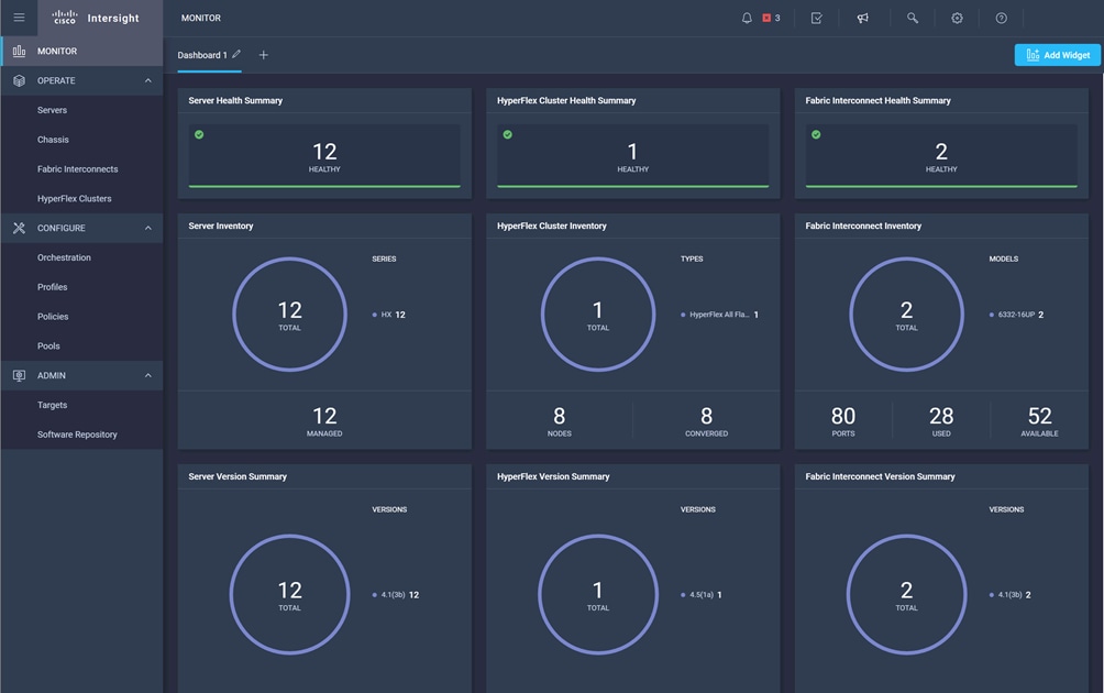
The Cisco Intersight platform (https://intersight.com) is Cisco’s latest visionary cloud-based management tool (Figure 2). It is designed to provide centralized off-site management, monitoring, and reporting capabilities for all your Cisco UCS solutions, and it can be used to deploy and manage Cisco HyperFlex clusters. The Cisco Intersight platform offers direct links to Cisco UCS Manager and Cisco HyperFlex Connect for the systems it is managing and monitoring. The Cisco Intersight website and framework is being constantly upgraded and extended with new and enhanced features independently of the products that are managed, meaning that many new features and capabilities can be added with no downtime or upgrades required by the end users. This unique combination of embedded and online technologies results in a complete cloud-based management solution that can care for your Cisco HyperFlex systems throughout the entire lifecycle, from deployment through retirement.
The Cisco UCS Fabric Interconnect (FI) is a core part of the Cisco Unified Computing System, providing both network connectivity and management capabilities for the system. Depending on the model chosen, the Cisco UCS Fabric Interconnect offers line-rate, low-latency, lossless 10 Gigabit, 25 Gigabit, 40 Gigabit, or 100 Gigabit Ethernet, Fibre Channel over Ethernet (FCoE) and Fibre Channel connectivity. Cisco UCS Fabric Interconnects provide the management and communication backbone for the Cisco UCS C-Series, S-Series and HX-Series Rack-Mount Servers, Cisco UCS B-Series Blade Servers, and Cisco UCS 5100 Series Blade Server Chassis. All servers and chassis, and therefore all blades, attached to the Cisco UCS Fabric Interconnects become part of a single, highly available management domain. In addition, by supporting unified fabrics, the Cisco UCS Fabric Interconnects provide both the LAN and SAN connectivity for all servers within its domain.
Cisco HyperFlex HX Data Platform Software
The Cisco HyperFlex HX Data Platform is a purpose-built, high-performance, distributed file system with a wide array of enterprise-class data management services. The data platform’s innovations redefine distributed storage technology, exceeding the boundaries of first-generation hyperconverged infrastructures. The data platform has all the features expected in an enterprise shared storage system, eliminating the need to configure and maintain complex Fibre Channel storage networks and devices. The platform simplifies operations and helps ensure data availability. Enterprise-class storage features include the following:
● Data protection creates multiple copies of the data across the cluster so that data availability is not affected if single or multiple components fail (depending on the replication factor configured).
● Deduplication is always on, helping reduce storage requirements in virtualization clusters in which multiple operating system instances in guest virtual machines result in large amounts of replicated data.
● Compression further reduces storage requirements, reducing costs, and the log-structured file system is designed to store variable-sized blocks, reducing internal fragmentation.
● Replication copies virtual machine–level snapshots from one Cisco HyperFlex cluster to another to facilitate recovery from a cluster or site failure through failover to the secondary site of all the virtual machines.
● Thin provisioning allows large volumes to be created without requiring storage to support them until the need arises, simplifying data volume growth and making storage a "pay as you grow" proposition.
● Fast, space-efficient clones rapidly duplicate virtual storage volumes so that virtual machines can be cloned simply through metadata operations, with actual data copied only for write operations.
● Snapshots help facilitate backup and remote-replication operations, which are needed in enterprises that require always-on data availability.
● Small Computer System Interface over IP (iSCSI) connectivity allows external systems to consume HX Data Platform storage by presenting volumes to be mounted by the external systems using the iSCSI protocol.
Cisco HyperFlex HX Data Platform Controller
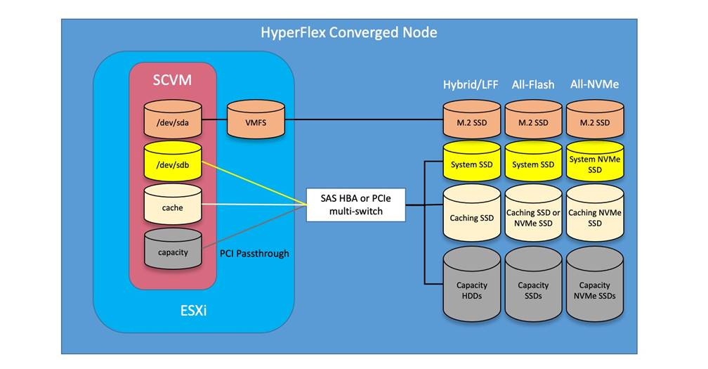
A Cisco HyperFlex HX Data Platform controller resides on each node and implements the distributed file system. The controller runs as software in user space within a virtual machine and intercepts and handles all I/O from the guest virtual machines. The storage controller virtual machine (SCVM) uses the VMDirectPath I/O feature to provide direct PCI passthrough control of the physical server’s SAS disk controller or direct control of the PCI-attached NVMe-based solid-state disks (SSDs). This method gives the controller virtual machine full control of the physical disk resources, using the SSD drives as a read-write caching layer and using the hard-disk drives (HDDs) or SSDs as a capacity layer for distributed storage.
The controller integrates the data platform into the VMware vSphere cluster through the use of three preinstalled VMware ESXi vSphere Installation Bundles (VIBs) on each node:
● scvmclient: This VIB, also called the Cisco HyperFlex IO Visor, provides a network file system (NFS) mount point so that the ESXi hypervisor can access the virtual disks that are attached to individual virtual machines. From the hypervisor’s perspective, it is simply attached to a network file system. The IO Visor intercepts guest virtual machine I/O traffic and intelligently redirects it to the Cisco HyperFlex SCVMs.
● STFSNasPlugin: The VMware API for Array Integration (VAAI) storage offload API allows vSphere to request advanced file system operations such as snapshots and cloning. The controller implements these operations through manipulation of the file system metadata rather than actual data copying, providing rapid response, and thus rapid deployment of new environments.
● stHypervisorSvc: This VIB adds enhancements and features needed for Cisco HyperFlex data protection and virtual machine replication.
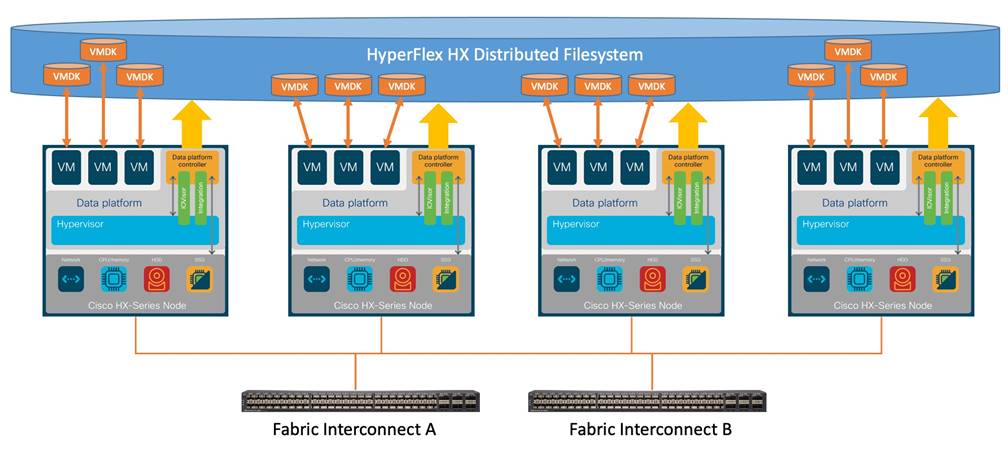
Data Operations and Distribution
The Cisco HyperFlex HX Data Platform controllers handle all read and write operation requests from the guest virtual machines to their virtual disks (VMDKs) stored in the distributed data stores in the cluster. The data platform distributes the data across multiple nodes of the cluster, and also across multiple capacity disks for each node, according to the replication-level policy selected during the cluster setup. This method avoids storage hotspots on specific nodes, and on specific disks of the nodes, and thereby also avoids networking hotspots, or congestion caused by accessing more data on some nodes than others.
The policy for the number of duplicate copies of each storage block is chosen during cluster setup and is referred to as the replication factor (RF).
● Replication factor 3: For every I/O write committed to the storage layer, two additional copies of the blocks written will be created and stored in separate locations, for a total of three copies of the blocks. Blocks are distributed in such a way as to ensure that multiple copies of the blocks are not stored on the same disks, nor on the same nodes of the cluster. This setting can tolerate simultaneous failures of two entire nodes in a cluster of five nodes or more without losing data or requiring restore-from-backup or other recovery processes. RF=3 is recommended for all production systems and is the default for all clusters of three nodes or more.
● Replication factor 2: For every I/O write committed to the storage layer, one additional copy of the blocks written will be created and stored in separate locations, for a total of two copies of the blocks. Blocks are distributed in such a way as to ensure that multiple copies of the blocks are not stored on the same disks, nor on the same nodes of the cluster. This setting can tolerate a failure of one entire node without losing data or requiring restore-from-backup or other recovery processes. RF=2 is suitable for nonproduction systems and for environments for which the extra data protection is not needed.
Data write, encryption and compression operations
Internally, the contents of each guest virtual machine's virtual disks are subdivided and spread across multiple servers by the HX Data Platform software. For each write operation, the data is intercepted by the IO Visor module on the node on which the virtual machine is running, a primary node is determined for that particular operation through a hashing algorithm, and then the data is sent to the primary node through the network. The primary node compresses the data in real time and writes the compressed data to the write log on its caching SSD. If the cluster is enabled for data-at-rest encryption, then the data is also encrypted by the primary node when writing it to the caching disk. Next, replica copies of that encrypted and/or compressed data are sent through the network and written to the write log on the caching SSD of the remote nodes in the cluster, according to the replication factor setting.
For example, at RF=3, a write operation will be written to the write log of the primary node for that virtual disk address, and two additional write operations will be committed in parallel on two other nodes. Because the virtual disk contents have been divided and spread out by the hashing algorithm for each unique operation, this method results in all write operations being spread across all nodes, avoiding problems with data locality and with "noisy" virtual machines consuming all the I/O capacity of a single node. The write operation will not be acknowledged until all three copies are written to the caching layer SSDs. Written data is also cached in a write log area resident in memory in the controller virtual machine, along with the write log on the caching SSDs. This process speeds up read requests when read operations are requested for data that has recently been written.
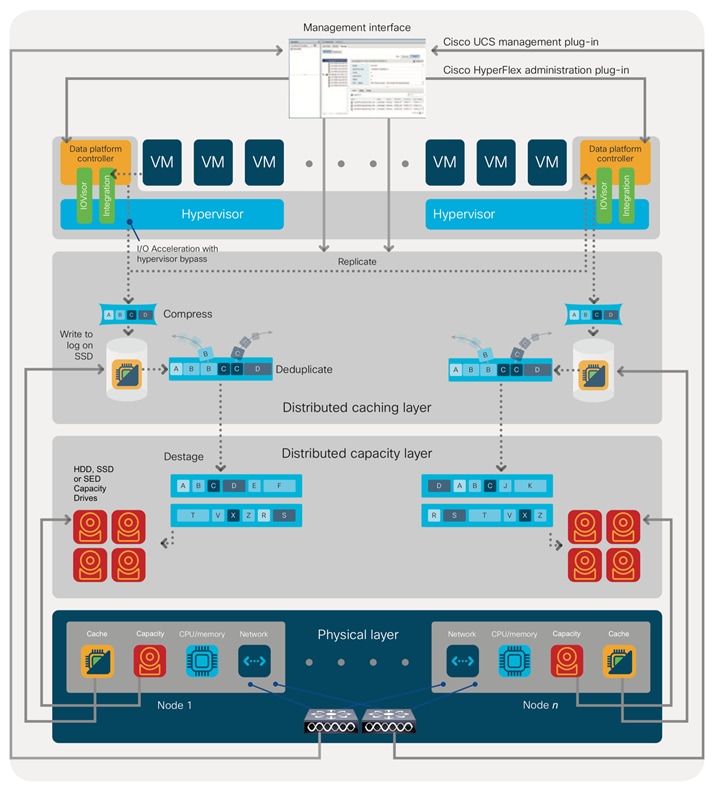
Data destaging and deduplication
The Cisco HyperFlex HX Data Platform constructs multiple write log caching segments on the caching SSDs of each node in the distributed cluster. As write cache segments become full and based on policies accounting for I/O load and access patterns, those write cache segments are locked, and new write operations roll over to a new write cache segment. The data in the now-locked cache segment is then deduplicated and destaged to the capacity layer of the nodes for long-term storage. On hybrid systems, the now-deduplicated and compressed data is also written to the dedicated read cache area of the caching SSD, which speeds up read requests for data that has recently been written. When the data is destaged to the capacity disks, it is written in a single sequential operation, avoiding disk-head seek thrashing on the spinning disks and accomplishing the task in the least amount of time. Because the data is already deduplicated and compressed before it is written, the platform avoids the additional I/O overhead often experienced on competing systems, which must then later perform a read, deduplication, compress, and write cycle.
Figure 3 shows this data movement.
For data read operations, data may be read from multiple locations. For data that was very recently written, the data is likely to still exist in the write log of the local platform controller memory or in the write log of the local caching layer disk. If local write logs do not contain the data, the distributed file system metadata will be queried to see if the data is cached elsewhere, either in write logs of remote nodes or in the dedicated read cache area of the local and remote caching SSDs of hybrid nodes. Finally, if the data has not been accessed in a significant amount of time, the file system will retrieve the requested data from the distributed capacity layer. As requests for read operations are made to the distributed file system and the data is retrieved from the capacity layer, the caching SSDs of hybrid nodes populate their dedicated read cache area to speed up subsequent requests for the same data. This multitiered distributed system with several layers of caching techniques helps ensure that data is served at the highest possible speed, using the caching SSDs of the nodes fully and equally. All-flash configurations do not employ a dedicated read cache; such caching would not provide any performance benefit because the persistent data copy already resides on high-performance SSDs.
In summary, the Cisco HyperFlex HX Data Platform implements a distributed, log-structured file system that performs data operations through two configurations:
● In a hybrid configuration, the data platform provides a caching layer using SSDs to accelerate read requests and write responses, and it implements a storage capacity layer using HDDs.
● In an all-flash or all-NVMe configuration, the data platform provides a dedicated caching layer using high-endurance SSDs to accelerate write responses, and it implements a storage capacity layer also using SSDs. Read requests are fulfilled directly from the capacity SSDs, because a dedicated read cache is not needed to accelerate read operations.
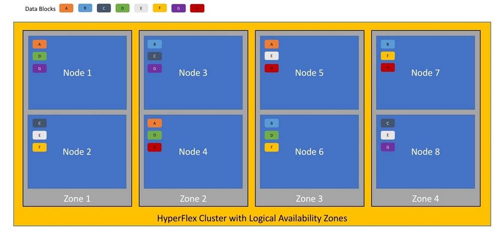
Larger scale HyperFlex clusters are subject to higher failure risks, simply due to the number of nodes in the cluster. While any individual node’s risk of failure is the same no matter how many nodes there are, with clusters up to 32 converged nodes in size, there is a logically higher probability that a single node could fail, when compared to a cluster with fewer nodes. To mitigate these risks in larger scale clusters, a HyperFlex cluster of eight nodes or more can be configured with a feature called Logical Availability Zones (LAZ). The Logical Availability Zones feature groups 2 or more HyperFlex nodes together into a logically defined zone, a minimum of 3 zones are created, and the data in the cluster is distributed in such a way that no blocks are written to the nodes within a single zone more than once. Due to this enhanced distribution pattern of data across zones, wherein each zone has multiple servers, clusters with LAZ enabled can typically withstand more failures than clusters which operate without it. The number of failures that can tolerated varies depending on the number of zones in the cluster, and the number of servers in each of the zones. Generally speaking, multiple node failures across one or two zones will be tolerated better, and with less risk than multiple nodes failing across three or more zones. Note that the failure tolerance shown in the HyperFlex Connect dashboard will always present a “worst case scenario” view, meaning that even though the dashboard may state that two failures can be tolerated, in fact two servers could fail and the cluster can remain online, and the failure tolerance may still remain at two.
Logical availability zones should not be confused with the concept of fault domains. An example of a fault domain would be a subset of the nodes in a single HyperFlex cluster being powered by one uninterruptable power supply (UPS) or connected to one power distribution unit (PDU), meanwhile the remaining nodes would be connected to another UPS or PDU. If one of the UPS’ or PDUs were to fail, then there would be a simultaneous failure of multiple nodes. While LAZ may actually prevent the cluster from failing in this scenario, to guarantee it would require that the zone membership be manually controlled, so that a failure of all of the servers protected by a single UPS or PDU, would be distributed in such a way that it would not cause an outage. The LAZ feature is not designed to be manually configured in this way, instead the zone membership is determined automatically by the system. If a HyperFlex cluster needs to be physically split in half due to a physical limitation, such as the UPS example above, or a distance requirement for fault tolerance, then the cluster should be built as a stretched cluster instead of using LAZ.
Figure 4 illustrates an example of the data distribution method for clusters with Logical Availability Zones enabled, set to replication factor 3, where each zone only contains one of the three copies of the data in the cluster. This cluster consists of eight nodes, which the system configures into four zones.
Logical availability zones are subject to the following requirements and limitations:
● Only HyperFlex clusters with 8 nodes or more can be configured with logical availability zones during the installation process.
● Logical Availability Zones can be enabled during the HyperFlex cluster installation, or it can be enabled via the command line at a later time. It is recommended to enable this feature during installation, in order to avoid a large migration and reorganization of data across the cluster, which would be necessary to comply with the data distribution rules if LAZ is turned on in a cluster already containing data.
● The number of zones can be manually specified as 3, 4, 5, or you can allow the installer to automatically choose, which is the recommended setting.
● The HyperFlex cluster determines which nodes participate in each zone, and this configuration cannot be modified.
● To maintain the most balanced consumption of space and data distribution, it is recommended that the number of nodes in a cluster are whole multiples of 3, 4, 5, or 7. For example, 8 nodes would evenly divide into 4 zones of 2 servers each, and 9 nodes would divide evenly into 3 zones of 3 servers each. Eleven nodes would create an unbalanced number of nodes across the zones, leading to unbalanced space consumption on the nodes.
● In addition to the previous point, expansion of a cluster should be done in multiples of the number of zones, when the cluster is operating with LAZ enabled. Expanding in such a way preserves a matched number of nodes in each zone and prevents any unbalance of space consumption. For example, a cluster with 3 zones should be expanded by adding 3 more nodes, because adding only 1 or 2 nodes would lead to an imbalance, as would adding 4 nodes.
All-NVMe and All-Flash versus Hybrid Nodes
Cisco HyperFlex systems can be divided logically into two families: a collection of hybrid nodes, and a collection of all-flash or all-NVMe nodes.
Hybrid nodes use a combination of SSDs for the short-term storage caching layer and HDDs for the long-term storage capacity layer. The hybrid Cisco HyperFlex system is an excellent choice for entry-level or midrange storage solutions, and hybrid solutions have been successfully deployed in many nonperformance-sensitive virtual environments.
However, the number highly performance-sensitive and mission-critical applications being deployed is increasing rapidly. The primary challenge to hybrid Cisco HyperFlex systems for these performance-sensitive applications is their increased sensitivity to storage latency. Due to the characteristics of the spinning hard disks, which results in higher latency, HDDs almost inevitably become a bottleneck in a hybrid system. Ideally, if all the storage operations occurred on the caching SSD layer, the hybrid system’s performance would be excellent. But in some scenarios, the amount of data being written and read exceeds the caching layer capacity, placing larger loads on the HDD capacity layer, and the subsequent increase in latency results in reduced performance.
Cisco HyperFlex all-flash and all-NVMe systems are an excellent option for customers with high-performance, latency-sensitive workloads. Because the capacity layer disks are also SSDs, the all-flash and all-NVMe systems avoid the increased latency seen in hybrid nodes when large amounts of data are written and read. With a purpose-built, flash-optimized, high-performance log-based file system, the Cisco HyperFlex all-flash and all-NVMe systems provide these features:
● Predictable high performance across all the virtual machines the cluster
● Highly consistent and low latency, which benefits data-intensive applications
● Architecture that can continue to meet your needs in the future; it is well suited for flash-memory configuration, reducing write amplification and flash cell wear
● Cloud-scale solution with easy scale-out and distributed infrastructure and the flexibility to scale out independent resources separately
Cisco HyperFlex support for hybrid, all-flash, and all-NVMe models allows customers to choose the right platform configuration based on their capacity, applications, performance, and budget requirements. All-flash configurations offer repeatable and sustainable high performance, especially for scenarios with a larger working set of data—that is, a large amount of data in motion. All-NVMe configurations elevate performance to an even higher level, with lower latencies for the most demanding applications. Hybrid configurations are a good option for customers who want the simplicity of the Cisco HyperFlex solution, but whose needs are focused on capacity-sensitive solutions, lower budgets, and few performance-sensitive applications.
Cisco HyperFlex Connect HTML 5 Management Webpage
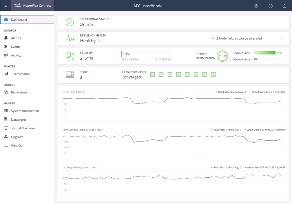
An HTML 5–based web user interface named Cisco HyperFlex Connect is available for use as the primary management tool for Cisco HyperFlex systems (Figure 4). Through this centralized point of control for the cluster, administrators can create data stores, monitor the data platform health and performance, manage resource use, and perform upgrades. Administrators can also use this management portal to predict when the cluster will need to be scaled, create virtual machine snapshot schedules, and configure native virtual machine replication. To use the Cisco HyperFlex Connect user interface, connect using a web browser to the Cisco HyperFlex cluster IP address: http://<hx controller cluster ip>.
This chapter contains the following:
This section is organized into the following subjects:
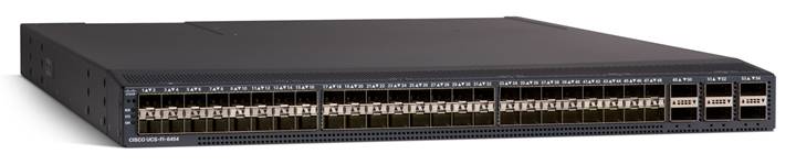
Cisco UCS 6454 Fabric Interconnect
The Cisco UCS 6454 Fabric Interconnect is a One-Rack-Unit (1RU) 10/25/40/100 Gigabit Ethernet, FCoE and Fibre Channel switch offering up to 3.82 Tbps throughput and up to 54 ports. The switch has 28 10/25-Gbps Ethernet ports, 4 1/10/25-Gbps Ethernet ports, 6 40/100-Gbps Ethernet uplink ports and 16 unified ports that can support 10/25-Gbps Ethernet ports or 8/16/32-Gbps Fibre Channel ports. All Ethernet ports are capable of supporting FCoE. Cisco HyperFlex nodes can connect at 10-Gbps or 25-Gbps speeds depending on the model of Cisco VIC card in the nodes and the SFP optics or cables chosen.
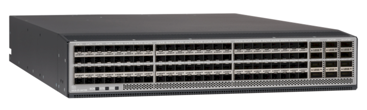
Cisco UCS 64108 Fabric Interconnect
The Cisco UCS 64108 Fabric Interconnect is a Two-Rack-Unit (2RU) 10/25/40/100 Gigabit Ethernet, FCoE and Fibre Channel switch offering up to 7.42 Tbps throughput and up to 108 ports. The switch has 72 10/25-Gbps Ethernet ports, 8 1/10/25-Gbps Ethernet ports, 12 40/100-Gbps Ethernet uplink ports and 16 unified ports that can support 10/25-Gbps Ethernet ports or 8/16/32-Gbps Fibre Channel ports. All Ethernet ports are capable of supporting FCoE. Cisco HyperFlex nodes can connect at 10-Gbps or 25-Gbps speeds depending on the model of Cisco VIC card in the nodes and the SFP optics or cables chosen.
Cisco HyperFlex HX220c-M6 converged nodes
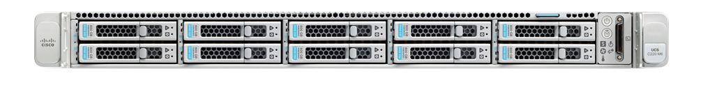
The Cisco HyperFlex HX220c-M6 converged node is a small footprint (1RU) Cisco HyperFlex model using third-generation Intel Xeon scalable processors and up to 4TB of RAM or DCPMM. It contains one or two 240 GB M.2 form factor solid-state disks (SSD) that acts as the boot drive. When two boot drives are ordered the optional HX-M2-HWRAID controller must be included to enable RAID 1 boot drive redundancy. Optionally, the Cisco HyperFlex Acceleration Engine card can be added to improve write performance and compression. Either Cisco VIC model 1467 quad-port 10/25 Gb, or model 1477 quad-port 40/100 Gb card may be selected.
Cisco HyperFlex HX220c-M6S model servers are hybrid nodes, using an SSD for both the system drive and the caching drive, and up to 8 traditional spinning hard disk drives (HDD) for the capacity disks. Cisco HyperFlex HXAF220c-M6S model servers are all-flash nodes and replace the capacity HDDs with SSDs for higher performance. Cisco HyperFlex HXAF220c-M6SN model servers are all-NVMe nodes, which replace all the system, caching, and capacity SSDs with NVMe based flash drives for the highest possible performance. A wide variety of drive models are available for use as the system, caching, and capacity drives, depending on the model of server. Please refer to the current online spec sheet for all of the available drive options: https://www.cisco.com/c/dam/en/us/products/collateral/hyperconverged-infrastructure/hyperflex-hx-series/hyperflex-hx220c-m6-nvme-spec-sheet.pdf
Cisco HyperFlex HX225c-M6 converged nodes
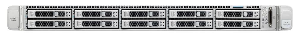
The HX225c-M6 converged node is a small footprint (1RU) Cisco HyperFlex model using AMD Rome, Milan, or Milan-X series processors and up to 4TB of RAM. It contains one or two 240 GB M.2 form factor solid-state disks (SSD) that acts as the boot drive. When two boot drives are ordered the optional HX-M2-HWRAID controller must be included to enable RAID 1 boot drive redundancy. Either Cisco VIC model 1467 quad-port 10/25 Gb, or model 1477 quad-port 40/100 Gb card may be selected.
Cisco HyperFlex HX225c-M6S model servers are hybrid nodes, using an SSD for both the system drive and the caching drive, and up to 8 traditional spinning hard disk drives (HDD) for the capacity disks. Cisco HyperFlex HXAF225c-M6S model servers are all-flash nodes and replace the capacity HDDs with SSDs for higher performance. A wide variety of drive models are available for use as the system, caching, and capacity drives, depending on the model of server. Please refer to the current online spec sheet for all of the available drive options: https://www.cisco.com/c/dam/en/us/products/collateral/hyperconverged-infrastructure/hyperflex-hx-series/hx225c-m6sx-specsheet.pdf
Cisco HyperFlex HX240c-M6 converged nodes
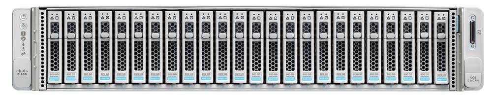
The HX240c-M6 converged node is a capacity optimized (2RU) Cisco HyperFlex model using third-generation Intel Xeon scalable processors and up to 8TB of RAM or DCPMM. It contains one or two 240 GB M.2 form factor solid-state disks (SSD) that acts as the boot drive. When two boot drives are ordered the optional HX-M2-HWRAID controller must be included to enable RAID 1 boot drive redundancy. Optionally, the Cisco HyperFlex Acceleration Engine card can be added to improve write performance and compression. Either Cisco VIC model 1467 quad-port 10/25 Gb, or model 1477 quad-port 40/100 Gb card may be selected.
Cisco HyperFlex HX240c-M6S model servers are hybrid nodes, using an SSD for both the system drive and the caching drive, and up to 24 traditional spinning hard disk drives (HDD) for the capacity disks. Cisco HyperFlex HX240c-M6L servers are hybrid models which utilize up to twelve 3.5” large form factor (LFF) HDDs for deployments with higher storage capacity requirements. Cisco HyperFlex HXAF240c-M6S model servers are all-flash nodes and replace the capacity HDDs with SSDs for higher performance. Cisco HyperFlex HXAF240c-M6SN model servers are all-NVMe nodes, which replace all the system, caching, and capacity SSDs with NVMe based flash drives for the highest possible performance. A wide variety of drive models are available for use as the system, caching, and capacity drives, depending on the model of server. Please refer to the current online spec sheet for all of the available drive options: https://www.cisco.com/c/dam/en/us/products/collateral/hyperconverged-infrastructure/hyperflex-hx-series/hyperflex-hx240c-m6-nvme-spec-sheet.pdf and https://www.cisco.com/c/dam/en/us/products/collateral/hyperconverged-infrastructure/hyperflex-hx-series/hyperflex-hx240c-m6-lff-spec-sheet.pdf
Cisco HyperFlex HX245c-M6 converged nodes
The HX245c-M6 converged node is a capacity optimized (2RU) Cisco HyperFlex model using AMD Rome, Milan, or Milan-X series processors and up to 8TB of RAM. It contains one or two 240 GB M.2 form factor solid-state disks (SSD) that acts as the boot drive. When two boot drives are ordered the optional HX-M2-HWRAID controller must be included to enable RAID 1 boot drive redundancy. Either Cisco VIC model 1467 quad-port 10/25 Gb, or model 1477 quad-port 40/100 Gb card may be selected.
Cisco HyperFlex HX245c-M6S model servers are hybrid nodes, using an SSD for both the system drive and the caching drive, and up to 24 traditional spinning hard disk drives (HDD) for the capacity disks. Cisco HyperFlex HXAF245c-M6S model servers are all-flash nodes and replace the capacity HDDs with SSDs for higher performance. A wide variety of drive models are available for use as the system, caching, and capacity drives, depending on the model of server. Please refer to the current online spec sheet for all of the available drive options: https://www.cisco.com/c/dam/en/us/products/collateral/hyperconverged-infrastructure/hyperflex-hx-series/hx245c-m6sx-specsheet.pdf
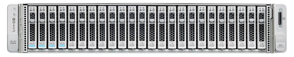 Table 1 lists the required physical components and hardware.
Table 1. Cisco HyperFlex System Components
| Component |
Hardware |
| Fabric Interconnects |
Two (2) Cisco UCS 6454 or 64108 Fabric Interconnects |
| Servers |
Minimum of (3) three and up to (32) thirty-two Cisco UCS HX-series servers. Choose from models:
● Cisco HyperFlex HX220c M6S
● Cisco HyperFlex HX225c M6S
● Cisco HyperFlex HX240c M6SX
● Cisco HyperFlex HX245c M6SX
● Cisco HyperFlex HXAF220c M6S
● Cisco HyperFlex HXAF225c M6S
● Cisco HyperFlex HXAF240c M6SX
● Cisco HyperFlex HXAF245c M6SX
● Cisco HyperFlex HXAF220c M6SN
● Cisco HyperFlex HXAF240c M6SN
Or Minimum of (3) three and up to (16) sixteen Cisco UCS HX-series servers. Choose from models:
● Cisco HyperFlex HX240c M6L
|
The software components of the Cisco HyperFlex system must meet minimum requirements for the Cisco UCS firmware, hypervisor version, and the Cisco HyperFlex Data Platform software in order to interoperate properly. For the full details of software and hardware version requirements and compatibility, visit this page: https://www.cisco.com/c/en/us/td/docs/hyperconverged_systems/HyperFlex_HX_DataPlatformSoftware/release-guidelines-and-support-timeline/b-recommended-hx-data-platform-sw-releases/m-software-requirements-5-0.html
Table 2 lists the software components and the versions required for a single cluster of the Cisco HyperFlex, as tested, and validated in this document.
Table 2. Software Components and Hardware
| Component |
Hardware |
| Hypervisor |
VMware ESXi 6.7 U3, 7.0 U2 or 7.0 U3 CISCO Custom Image for ESXi 7.0 Update 3 for HyperFlex: HX-ESXi-7.0U3-20842708-Cisco-Custom-7.3.0.11-install-only.iso |
| Management Server |
VMware vCenter 6.7 U3, 7.0 U2 or 7.0 U3 |
| Cisco UCS Firmware |
Cisco UCS Infrastructure software, B-Series and C-Series bundles, revision 4.2(2d) or later |
| Cisco HyperFlex |
Cisco HyperFlex 5.0(2b) |
Cisco HyperFlex systems must be properly licensed using Cisco Smart Licensing, which is a cloud-based software licensing management solution used to automate many manual, time-consuming, and error-prone licensing tasks. The Cisco HyperFlex system communicates with the Cisco Smart Software Manager (SSM) online service through a Cisco Smart Account to check out or assign available licenses from the account to the Cisco HyperFlex cluster resources. Communications can be direct through the internet. You can also configure communication using a proxy server, or through an internal Cisco SSM satellite server, which caches and periodically synchronizes licensing data.
In a small number of highly secure environments, systems can be provisioned with a permanent license reservation (PLR), which does not need to communicate with Cisco SSM. Contact your Cisco sales representative or partner to discuss whether your security requirements will necessitate use of these permanent licenses.
New Cisco HyperFlex cluster installations will operate for 90 days without licensing to provide an evaluation period. Thereafter, the system will generate alarms and operate in a noncompliant mode. Systems without compliant licensing will not be entitled to technical support.
For more information about the Cisco Smart Software Manager satellite server, visit this website: https://www.cisco.com/c/en/us/buy/smart-accounts/software-manager-satellite.html.
Licensing of the Cisco HyperFlex DC-No-FI system requires one license per node from one of two license editions: Cisco HyperFlex Datacenter Advantage or Datacenter Premier. The type of cluster being installed and the features you want to activate and use in the system determine the licenses you need to purchase and the appropriate licensing tier.
Additional features in the future will be added to the different licensing editions as they are released. The features listed in Table 3 are current as of the publication of this document.
Table 3. Cisco HyperFlex system license editions
| Cisco HyperFlex license edition |
Cisco HyperFlex Datacenter Advantage |
Cisco HyperFlex Datacenter Premier |
| Features |
● Cisco HyperFlex installation on all supported models other than all-NVMe nodes
● 1:1 ratio of compute-only nodes to converged nodes
● In-line compression and deduplication
● Self-encrypting drives
● Logical Availability Zones
● iSCSI storage
● Snapshots and replication
|
Everything in the Advantage license plus:
● Cisco HyperFlex installation on all-NVMe nodes
● 2:1 ratio of compute-only nodes to converged nodes
● Software encryption
● Cisco HyperFlex Acceleration Engine card
● Stretch clusters
|
| Tech tip |
| To enable software encryption, each server in the cluster will also require, at minimum, Intersight Essentials license Before enabling Software Encryption on a cluster, a customer also needs to purchase a special software PID (HXDP-SW-PKG-SE-K9=) |
For a comprehensive guide to licensing and all the features in each edition, consult the Cisco HyperFlex Licensing Guide here: https://www.cisco.com/c/en/us/td/docs/hyperconverged_systems/HyperFlex_HX_DataPlatformSoftware/HX-Ordering-and-Licensing-Guide/b_Cisco_HyperFlex_Systems_Ordering_and_Licensing_Guide.html.
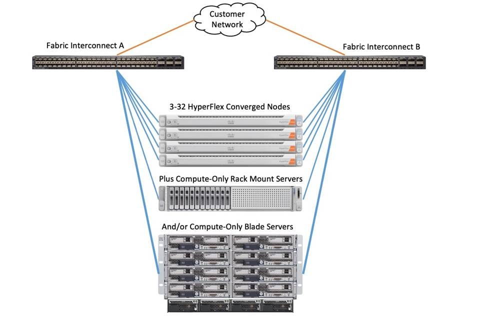
The Cisco HyperFlex system is composed of a pair of Cisco UCS Fabric Interconnects along with up to thirty-two HX-Series rack-mount servers per cluster. Up to thirty-two compute-only servers can also be added per HyperFlex cluster. Adding Cisco UCS rack-mount servers and/or Cisco UCS 5108 blade chassis, which house Cisco UCS blade servers, allows for additional compute resources in an extended cluster design. The two fabric interconnects both connect to every HX-Series rack-mount server, and both connect to every Cisco UCS 5108 blade chassis, and Cisco UCS rack-mount server. Upstream network connections, also referred to as “northbound” network connections are made from the Fabric Interconnects to the customer datacenter network at the time of installation.
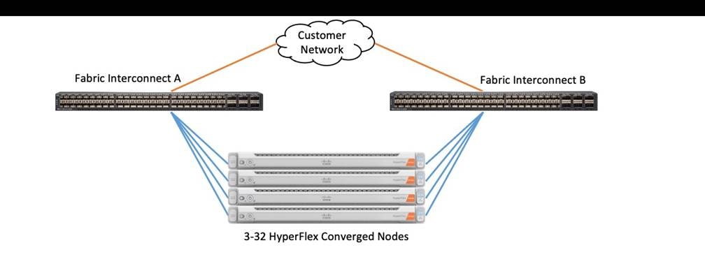
Cisco UCS network uplinks connect “northbound” from the pair of Cisco UCS Fabric Interconnects to the LAN in the customer datacenter. All Cisco UCS uplinks operate as trunks, carrying multiple 802.1Q VLAN IDs across the uplinks. The default Cisco UCS behavior is to assume that all VLAN IDs defined in the Cisco UCS configuration are eligible to be trunked across all available uplinks.
Cisco UCS Fabric Interconnects appear on the network as a collection of endpoints versus another network switch. Internally, the Fabric Interconnects do not participate in spanning-tree protocol (STP) domains, and the Fabric Interconnects cannot form a network loop, as they are not connected to each other with a layer 2 Ethernet link. All link up/down decisions via STP will be made by the upstream root bridges.
Uplinks need to be connected and active from both Fabric Interconnects. For redundancy, multiple uplinks can be used on each FI, either as 802.3ad Link Aggregation Control Protocol (LACP) port-channels or using individual links. For the best level of performance and redundancy, uplinks can be made as LACP port-channels to multiple upstream Cisco switches using the virtual port channel (vPC) feature. Using vPC uplinks allows all uplinks to be active passing data, plus protects against any individual link failure, and the failure of an upstream switch. Other uplink configurations can be redundant, however spanning-tree protocol loop avoidance may disable links if vPC is not available.
All uplink connectivity methods must allow for traffic to pass from one fabric interconnect to the other, or from fabric A to fabric B. There are scenarios where cable, port or link failures would require traffic that normally does not leave the Cisco UCS domain, to instead be directed over the Cisco UCS uplinks because that traffic must travel from fabric A to fabric B, or vice-versa. Additionally, this traffic flow pattern can be seen briefly during maintenance procedures, such as updating firmware on the fabric interconnects, which requires them to be rebooted. Cisco recommends that the uplink bandwidth configured is greater than or equal to double the bandwidth available to each HyperFlex converged node. For example, if the nodes are connected at 10 Gigabit speeds, then each fabric interconnect should have at least 20 Gigabit of uplink bandwidth available. The following sections and figures detail several uplink connectivity options.
Single Uplinks to Single Switch
This connection design is susceptible to failures at several points; single uplink failures on either fabric interconnect can lead to connectivity losses or functional failures, and the failure of the single uplink switch will cause a complete connectivity outage.
Port Channels to Single Switch
This connection design is now redundant against the loss of a single link but remains susceptible to the failure of the single switch.
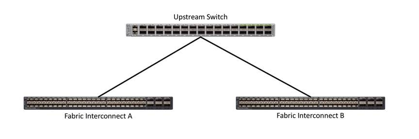
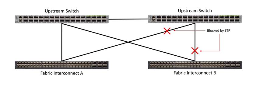
Single Uplinks or Port Channels to Multiple Switches
This connection design is redundant against the failure of an upstream switch, and redundant against a single link failure. In normal operation, STP is likely to block half of the links to avoid a loop across the two upstream switches. The side effect of this is to reduce bandwidth between the Cisco UCS domain and the LAN. If any of the active links were to fail, STP would bring the previously blocked link online to provide access to that fabric interconnect via the other switch. It is not recommended to connect both links from a single FI to a single switch, as that configuration is susceptible to a single switch failure breaking connectivity from fabric A to fabric B. For enhanced redundancy, the single links in the figure below could also be port-channels.
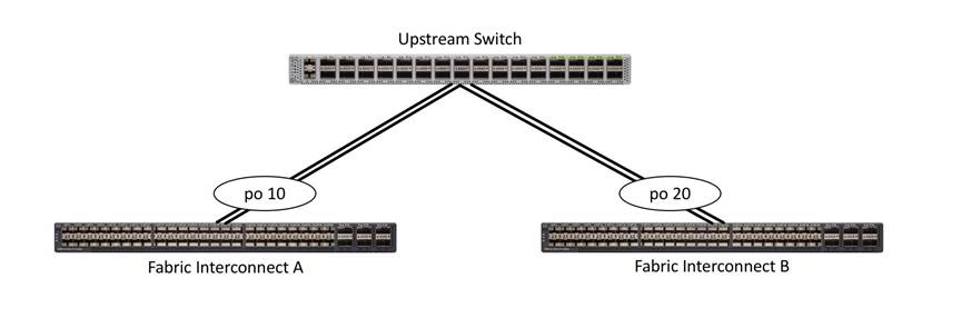
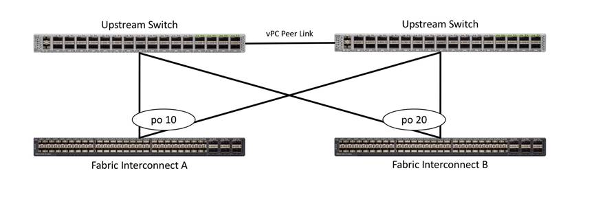
vPC to Multiple Switches
This recommended connection design relies on using Cisco switches that have the virtual port channel feature, such as Catalyst 6000 series switches running VSS, Cisco Nexus 5000 series, and Cisco Nexus 9000 series switches. Logically the two vPC enabled switches appear as one, and therefore spanning-tree protocol will not block any links. This configuration allows for all links to be active, achieving maximum bandwidth potential, and multiple redundancy at each level.
Fabric Interconnects (FI) are deployed in pairs, wherein the two units operate as a management cluster, while forming two separate network fabrics, referred to as the A side and B side fabrics. Therefore, many design elements will refer to FI A or FI B, alternatively called fabric A or fabric B. Both Fabric Interconnects are active at all times, passing data on both network fabrics for a redundant and highly available configuration. Management services, including Cisco UCS Manager, are also provided by the two FIs but in a clustered manner, where one FI is the primary, and one is secondary, with a roaming clustered IP address. This primary/secondary relationship is only for the management cluster and has no effect on data transmission.
Fabric interconnects have the following ports, which must be connected for proper management of the Cisco UCS domain:
● Mgmt: A 10/100/1000 Mbps port for managing the Fabric Interconnect and the Cisco UCS domain via GUI and CLI tools. This port is also used by remote KVM, IPMI and SoL sessions to the managed servers within the domain. This is typically connected to the customer management network.
● L1: A cross connect port for forming the Cisco UCS management cluster. This port is connected directly to the L1 port of the paired Fabric Interconnect using a standard CAT5 or CAT6 Ethernet cable with RJ45 plugs. It is not necessary to connect this to a switch or hub.
● L2: A cross connect port for forming the Cisco UCS management cluster. This port is connected directly to the L2 port of the paired Fabric Interconnect using a standard CAT5 or CAT6 Ethernet cable with RJ45 plugs. It is not necessary to connect this to a switch or hub.
● Console: An RJ45 serial port for direct console access to the fabric interconnect. This port is typically used during the initial FI setup process with the included serial to RJ45 adapter cable. This can also be plugged into a terminal aggregator or remote console server device.
HX-Series Server Connectivity
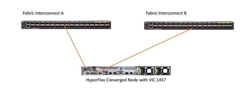
The HX-Series converged servers are connected directly to the Cisco UCS Fabric Interconnects in Direct Connect mode. This option enables Cisco Intersight and Cisco UCS Manager to manage the HX-Series Rack-Mount Servers using a single cable for both management traffic and data traffic. Cisco HyperFlex M6 generation servers can be configured with the Cisco VIC 1467 or VIC 1477 cards. For the Cisco VIC 1467 and VIC 1477 cards, the standard and redundant practice is to connect port 1 of the VIC card (the left-hand most port) to a port on FI A and connect port 3 (the right-center port) to a port on FI B (Figure 18). An optional configuration method for servers containing the Cisco VIC 1467 or VIC 1477 card is to cable the servers with 2 links to each FI, using ports 1 and 2 to FI A, and ports 3 and 4 to FI B. The HyperFlex installer checks for these configurations, and that all servers’ cabling matches. Failure to follow this cabling best practice can lead to errors, discovery failures, and loss of redundant connectivity.
All nodes within a Cisco HyperFlex cluster must be connected at the same communication speed, for example, mixing 10 Gb with 25 Gb interfaces is not allowed, and all of the nodes within a cluster must contain the same model of Cisco VIC cards. For servers with the Cisco UCS VIC 1467 installed, both 10 Gb and 25 Gb speeds are available when connected to a model 6454 or 64108 Fabric Interconnect. The speed of the links are dependent on the model of optics and cables used to connect the servers to the Fabric Interconnects. For servers with the Cisco UCS VIC 1477 installed, both 40 Gb and 100 Gb speeds are available.
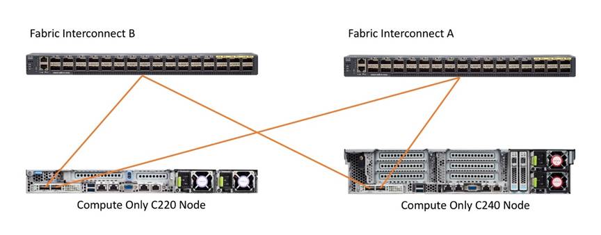
Cisco UCS B-Series Blade Servers
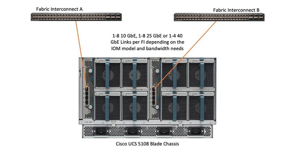
HyperFlex extended clusters can also incorporate 1-32 Cisco UCS blade servers for additional compute capacity. The blade chassis comes populated with 1-4 power supplies, and 8 modular cooling fans. In the rear of the chassis are two bays for installation of Cisco Fabric Extenders. The Fabric Extenders (also commonly called IO Modules, or IOMs) connect the chassis to the Fabric Interconnects. Internally, the Fabric Extenders connect to the Cisco VIC card installed in each blade server across the chassis backplane. The standard connection practice is to connect 1-8 10 GbE links, 1-8 25 GbE links, or 1-4 40 GbE links (depending on the IOMs and FIs purchased) from the left-side IOM, or IOM 1, to FI A, and to connect the same number of 10 GbE, 25 GbE or 40 GbE links from the right-side IOM, or IOM 2, to FI B (Figure 19). All other cabling configurations are invalid, and can lead to errors, discovery failures, and loss of redundant connectivity.
Cisco UCS C-Series Rack-Mount Servers
HyperFlex extended clusters can also incorporate 1-32 Cisco UCS Rack-Mount Servers for additional compute capacity. The Cisco UCS C-Series Rack-Mount Servers are connected directly to the Cisco UCS Fabric Interconnects in Direct Connect mode. The model of Cisco VIC card in the servers, the model of optics or physical transceivers, and the model of fabric interconnects must be compatible to establish links between the equipment. The standard and redundant connection practice for connecting standard Cisco UCS C-Series servers to the fabric interconnects is identical to the method described earlier for the HX-Series servers. Failure to follow this cabling practice can lead to errors, discovery failures, and loss of redundant connectivity.
Installing the HyperFlex system is done via the Cisco Intersight online management portal, or through a deployable HyperFlex installer virtual machine, available for download at cisco.com as an OVA file. The installer performs the configuration of Cisco UCS Manager, the physical servers, and also performs significant portions of the ESXi configuration. Finally, the installer will install the HyperFlex HX Data Platform software and create the HyperFlex cluster. The details of the logical network and ESXi host designs as installed by the HyperFlex installer follows below.
Cisco HyperFlex Logical Network Design
Cisco HyperFlex clusters can be installed with the choice between 10Gb, 25Gb and 40Gb Ethernet bandwidth, with two connections per server to the dual redundant upstream Fabric Interconnects.
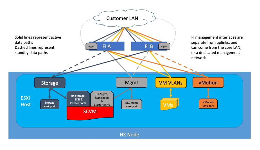
The Cisco HyperFlex system has communication pathways that fall into four defined zones (Figure 20):
● Management Zone: This zone comprises the connections needed to manage the physical hardware, the hypervisor hosts, and the storage platform controller virtual machines (SCVM).
● VM Zone: This zone comprises the connections needed to service network IO to the guest VMs that will run inside the HyperFlex hyperconverged system. This zone typically contains multiple routable VLANs, which are trunked to the Cisco UCS Fabric Interconnects via the network uplinks and tagged with 802.1Q VLAN IDs. For the Red Hat OpenShift Container Platform installation, the RHOCP master and worker VMs' networking endpoints would reside in this zone.
● Storage Zone: This zone comprises the connections used by the Cisco HX Data Platform software, ESXi hosts, and the storage controller VMs to service the HX Distributed Data Filesystem. The HX storage VLAN does not need to be routable to the rest of the LAN, however it must be able to traverse the switches upstream from the Fabric Interconnects. In addition, a VLAN for iSCSI-based traffic is created in this zone, which may or may not be routable according to the network design. Within this VLAN, the iSCSI storage IP addresses, one per node and one for the entire cluster, are created for presenting HXDP storage to external clients via the iSCSI protocol. These addresses are used in this design by the stateful containers which mount iSCSI-based volumes using the HX CSI plugin.
● VMotion Zone: This zone comprises the connections used by the ESXi hosts to enable vMotion of the guest VMs from host to host.
For the base HyperFlex system configuration, multiple VLANs need to be carried to the Cisco UCS domain from the upstream LAN, and these VLANs are also defined in the Cisco UCS configuration. The hx-storage-data VLAN must be a separate VLAN ID from the remaining VLANs. Table 4 lists the VLANs created by the HyperFlex installer in Cisco UCS, and their functions.
| VLAN Name |
VLAN ID |
Purpose |
| hx-inband-mgmt |
Customer supplied |
ESXi host management interfaces HX Storage Controller VM management interfaces HX Storage Cluster roaming management interface |
| hx-inband-repl |
Customer supplied |
HX Storage Controller VM Replication interfaces HX Storage Cluster roaming replication interface |
| hx-storage-data |
Customer supplied |
ESXi host storage VMkernel interfaces HX Storage Controller storage network interfaces HX Storage Cluster roaming storage interface |
| hx-inband-iscsi |
Customer supplied |
iSCSI external storage access |
| vm-network |
Customer supplied |
Guest VM network interfaces |
| hx-vmotion |
Customer supplied |
ESXi host vMotion VMkernel interfaces |
Note: A dedicated network or subnet for physical device management is often used in datacenters. In this scenario, the mgmt0 interfaces of the two Fabric Interconnects would be connected to that dedicated network or subnet. This is a valid configuration for HyperFlex installations with the following caveat; wherever the HyperFlex installer is deployed it must have IP connectivity to the subnet of the mgmt0 interfaces of the Fabric Interconnects, and also have IP connectivity to the subnets used by the hx-inband-mgmt VLANs listed above.
Jumbo Frames
All HyperFlex storage traffic traversing the hx-storage-data VLAN, and subnet is configured by default to use jumbo frames, or to be precise, all communication is configured to send IP packets with a Maximum Transmission Unit (MTU) size of 9000 bytes. The Cisco HyperFlex installer will configure jumbo frame support on the appropriate interfaces automatically. Jumbo frames could also significantly improve the performance of iSCSI traffic, which would also improve the performance of the Cisco HyperFlex CSI plugin for pods that require persistent storage. However, doing so can drastically increase the complexity of the configuration. Jumbo frame support requires that all interfaces, switches, initiators, and endpoints be configured properly to support the larger than standard MTU size. By default, the Red Hat OpenShift worker nodes would not be configured with a dedicated iSCSI interface with jumbo frame support enabled, and the Cisco HyperFlex CSI plugin would also not be configured to use jumbo frames. As such, although support for jumbo frames on the Cisco HyperFlex iSCSI network is possible, it is not recommended to attempt to use jumbo frames at this time.
ESXi Host Design
Building upon the Cisco UCS service profiles and policy designs, the following sections detail the design of the elements within the VMware ESXi hypervisors, system requirements, virtual networking, and the configuration of ESXi for the Cisco HyperFlex HX Distributed Data Platform.
The Cisco HyperFlex system has a pre-defined virtual network design at the ESXi hypervisor level. The ESXi host networking design is derived from the configuration of the nodes as set within Cisco UCS Manager, which is automatically configured via Cisco Intersight during the HyperFlex installation. Four different virtual switches are created by the HyperFlex installer, each using two uplinks, which are each serviced by a vNIC defined in the Cisco UCS service profile. The vSwitches created are:
● vswitch-hx-inband-mgmt: This is the default vSwitch0 which is renamed by the ESXi kickstart file as part of the automated installation. The switch has two uplinks, active on fabric A and standby on fabric B, without jumbo frames. The default VMkernel port, vmk0, is configured in the standard Management Network port group. A second port group is created for the Storage Platform Controller VMs to connect to with their individual management interfaces. A third port group is created for cluster-to-cluster VM snapshot replication traffic. The VLANs are not Native VLANs as assigned to the vNIC templates, and therefore they are defined in ESXi/vSphere.
● vswitch-hx-storage-data: This vSwitch is created as part of the automated installation. The switch has two uplinks, active on fabric B and standby on fabric A, with jumbo frames highly recommended. A VMkernel port, vmk1, is configured in the Storage Hypervisor Data Network port group, which is the interface used for connectivity to the HX Datastores via NFS. A second port group is created for the Storage Platform Controller VMs to connect to with their individual storage interfaces. A third and fourth port groups are created for external iSCSI traffic primary and secondary paths, although only the primary port group is used at this time and is assigned with the hx-inband-iscsi VLAN ID. The VLANs are not Native VLANs as assigned to the vNIC templates, and therefore they are defined in ESXi/vSphere.
● vswitch-hx-vm-network: This vSwitch is created as part of the automated installation. The switch has two uplinks, active on both fabrics A and B, and without jumbo frames. The VLANs are not Native VLANs as assigned to the vNIC templates, and therefore they are defined in ESXi/vSphere.
● vmotion: This vSwitch is created as part of the automated installation. The switch has two uplinks, active on fabric A and standby on fabric B, with jumbo frames highly recommended. The IP addresses of the VMkernel ports (vmk2) are configured during the post_install script execution. The VLAN is not a Native VLAN as assigned to the vNIC templates, and therefore they are defined in ESXi/vSphere.
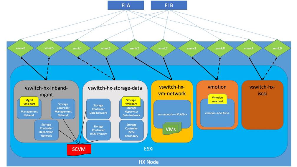
● vswitch-hx-iscsi: This additional standard vSwitch is only created when the optional additional pair of vNICs are created during installation for connectivity to external iSCSI storage systems. Port groups and VLAN ID assignment must be done manually as a post-installation activity.
Table 5 and Figure 22 provide more details about the ESXi virtual networking design as built by the HyperFlex installer by default.
Table 5. Default Virtual Switches
| Virtual Switch |
Port Groups |
Active vmnic(s) |
Passive vmnic(s) |
VLAN IDs |
Jumbo |
| vswitch-hx-inband-mgmt |
Management Network Storage Controller Management Network |
vmnic0 |
vmnic4 |
<<hx-inband-mgmt>> |
no |
| Storage Controller Replication Network |
vmnic0 |
vmnic4 |
<<hx-inband-repl>> |
no |
|
| vswitch-hx-storage-data |
Storage Controller Data Network Storage Hypervisor Data Network |
vmnic5 |
vmnic1 |
<<hx-storage-data>> |
yes |
| Storage Controller ISCSI Primary Storage Controller ISCSI Secondary |
vmnic5 |
vmnic1 |
<<hx-inband-iscsi>> |
yes |
|
| vswitch-hx-vm-network |
vm-network-<<VLAN ID>> |
vmnic2 vmnic6 |
<<vm-network>> |
no |
|
| vmotion |
vmotion-<<VLAN ID>> |
vmnic3 |
vmnic7 |
<<hx-vmotion>> |
yes |
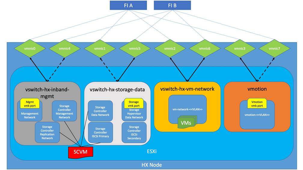
Table 6 and Figure 23 provide more details about the ESXi virtual networking design as built by the HyperFlex installer when the additional vNICs are configured during the installation.
Table 6. Optional Virtual Switches
| Virtual Switch |
Port Groups |
Active vmnic(s) |
Passive vmnic(s) |
VLAN IDs |
Jumbo |
| vswitch-hx-inband-mgmt
|
Management Network Storage Controller Management Network |
vmnic0 |
vmnic5 |
<<hx-inband-mgmt>> |
no |
| Storage Controller Replication Network |
vmnic0 |
vmnic5 |
<<hx-inband-repl>> |
no |
|
| vswitch-hx-storage-data
|
Storage Controller Data Network Storage Hypervisor Data Network |
vmnic6 |
vmnic1 |
<<hx-storage-data>> |
yes |
| Storage Controller ISCSI Primary Storage Controller ISCSI Secondary |
vmnic6 |
vmnic1 |
<<hx-inband-iscsi>> |
yes |
|
| vswitch-hx-vm-network |
vm-network-<<VLAN ID>> |
vmnic2 vmnic7 |
|
<<vm-network>> |
no |
| vmotion |
vmotion-<<VLAN ID>> |
vmnic3 |
vmnic8 |
<<hx-vmotion>> |
yes |
| vswitch-hx-iscsi |
User configured |
vmnic4 |
vmnic9 |
<<hx-ext-iscsi-a>> <<hx-ext-iscsi-b>> |
no |
Controller Virtual Machine Locations
The storage controller VM is operationally no different from any other typical virtual machine in an ESXi environment. The storage controller VM runs custom software and services which work cooperatively to form, manage, and maintain the Cisco HX Distributed Filesystem and service all the guest VM IO requests. The services and processes that run within the controller VMs are not exposed directly to the ESXi hosts, although the controller VMs are configured to automatically start and stop with the ESXi hosts and protected from accidental deletion. The deployment of the controller VMs and vCenter plugins are all done by the Cisco HyperFlex installer and requires no manual steps.
The VM must have a virtual disk with the bootable root filesystem available in a location separate from the SAS HBA that the VM is controlling via VMDirectPath I/O. The server boots the ESXi hypervisor from the internal M.2 form factor SSD(s). The boot disk is partitioned by the ESXi installer, and all remaining space is used as a VMFS datastore. The controller VM’s root filesystem is stored on a 2.5 GB virtual disk, /dev/sda, which is placed on this VMFS datastore. The controller VM has full control of all the front and rear facing SAS or NVMe based hot-swappable disks via PCI passthrough. The controller VM operating system mounts the system disk, also commonly called the “housekeeping” disk as /dev/sdb, and places HyperFlex binaries and logs on this disk. The remaining disks seen by the controller VM OS are used by the HX Distributed filesystem for caching and capacity layers.
The following figures detail the Storage Platform Controller VM placement on the ESXi hypervisor hosts.
Prior to the installation of the cluster, proper consideration must be given to the number of nodes required for the overall cluster scale, and the usable capacity that will result.
When using HX-series servers with Intel processors, Cisco HyperFlex standard clusters scale from a minimum of 3 to a maximum of 32 Cisco HX-series converged nodes with small form factor (SFF) disks per cluster. A converged node is a member of the cluster which provides storage resources to the HX Distributed Filesystem. For the compute intensive “extended” cluster design, a configuration with 3 to 32 Cisco HX-series converged nodes can be combined with up to 32 compute nodes. It is required that the number of compute-only nodes should always be less than or equal to number of converged nodes when using the HyperFlex Datacenter Advantage licenses. If using HyperFlex Datacenter Premier licenses, the number of compute-only nodes can grow to as much as twice the number of converged nodes. Regardless of the licensing used, the combined maximum size of any HyperFlex cluster cannot exceed 96 nodes. Once the maximum size of a single cluster has been reached, the environment can be “scaled out” by adding additional HX-series servers to the Cisco UCS domain, installing an additional HyperFlex cluster on those new servers, and managing them via the same vCenter server. There is no limit to the number of clusters that can be created in a single UCS domain, the practical limits will instead be reached due to the number of ports available on the Fabric Interconnects. Up to 100 HyperFlex clusters can be managed by a single vCenter server. Within Cisco Intersight, there are no practical limits to the number of Cisco HyperFlex clusters being managed.
Cisco HyperFlex HX240c-M6L model servers with large form factor (LFF) disks are limited to a maximum of sixteen nodes per cluster and cannot be mixed within the same cluster as models with small form factor (SFF) disks.
Table 7 lists the minimum and maximum scale for various installations of the Cisco HyperFlex system.
Table 7. HyperFlex Cluster Scale
| Cluster Type |
Minimum Converged Nodes Required |
Maximum Converged Nodes |
Maximum Compute-only Nodes Allowed |
Maximum Total Cluster Size |
| Intel and AMD based servers with SFF disks |
3 |
32 |
64 |
96 |
| Intel based servers with LFF disks |
3 |
16 |
32 |
48 |
Overall usable cluster capacity is based on a number of factors. The number of nodes in the cluster, the number and size of the capacity layer disks, and the replication factor of the HyperFlex HX Data Platform, all affect the cluster capacity. Caching disk sizes are not calculated as part of the cluster capacity.
Disk drive manufacturers have adopted a size reporting methodology using calculation by powers of 10, also known as decimal prefix. As an example, a 120 GB disk is listed with a minimum of 120 x 10^9 bytes of usable addressable capacity, or 120 billion bytes. However, many operating systems and filesystems report their space based on standard computer binary exponentiation, or calculation by powers of 2, also called binary prefix. Using this method, 2^10 or 1024 bytes make up a kilobyte, 2^10 kilobytes make up a megabyte, 2^10 megabytes make up a gigabyte, and 2^10 gigabytes make up a terabyte. As the sizes increase, the disparity between the two systems of measurement and notation gets worse, for example at the terabyte level, the deviation between a decimal prefix value and a binary prefix value is nearly 10 percent.
The International System of Units (SI) defines values and decimal prefix by powers of 10 as listed in Table 8.
Table 8. SI Unit Values (Decimal Prefix)
| Value |
Symbol |
Name |
| 1000 bytes |
kB |
Kilobyte |
| 1000 kB |
MB |
Megabyte |
| 1000 MB |
GB |
Gigabyte |
| 1000 GB |
TB |
Terabyte |
The International Organization for Standardization (ISO) and the International Electrotechnical Commission (IEC) defines values and binary prefix by powers of 2 in ISO/IEC 80000-13:2008 Clause 4 as listed in Table 9.
Table 9. IEC Unit Values (binary prefix)
| Value |
Symbol |
Name |
| 1024 bytes |
KiB |
Kibibyte |
| 1024 KiB |
MiB |
Mebibyte |
| 1024 MiB |
GiB |
Gibibyte |
| 1024 GiB |
TiB |
Tebibyte |
For the purpose of this document, the decimal prefix numbers are used only for raw disk capacity as listed by the respective manufacturers. For all calculations where raw or usable capacities are shown from the perspective of Cisco Intersight, Cisco HyperFlex software, filesystems or operating systems, the binary prefix numbers are used. This is done primarily to show a consistent set of values as seen by the end user from within Cisco Intersight or the HyperFlex Connect GUI when viewing cluster capacity, allocation, and consumption, and also within most operating systems.
Table 10 lists a set of HyperFlex HX Data Platform cluster usable capacity values, using binary prefix, for an array of cluster configurations. These values provide an example of the capacity calculations, for determining the appropriate size of HX cluster to initially purchase, and how much capacity can be gained by adding capacity disks. The calculations for these values are listed in Appendix A: Cluster Capacity Calculations. The HyperFlex tool to help with sizing is listed in Appendix B: HyperFlex Sizer.
Table 10. Example Cluster Usable Capacities
| HX-Series Server Model |
Node Quantity |
Capacity Disk Size (each) |
Capacity Disk Quantity (per node) |
Cluster Usable Capacity at RF=2 |
Cluster Usable Capacity at RF=3 |
| HXAF220c-M6S |
8 |
960 GB |
8 |
25.7 TiB |
17.1 TiB |
| 1.9 TB |
8 |
50.9 TiB |
33.9 TiB |
||
| HXAF240c-M6SX |
12 |
1.9 TB |
10 |
95.4 TiB |
63.6 TiB |
| 15 |
143.1 TiB |
95.4 TiB |
|||
| 23 |
219.4 TiB |
146.3 TiB |
|||
| 7.6 GB |
10 |
381.6 TiB |
254.4 TiB |
||
| 15 |
572.3 TiB |
381.6 TiB |
|||
| 23 |
877.6 TiB |
585.0 TiB |
|||
| HX240c-M6L |
16 |
6 TB |
6 |
241.0 TiB |
160.7 TiB |
| 16 |
642.6 TiB |
428.4 TiB |
|||
| 12 TB |
6 |
482.0 TiB |
321.3 TiB |
||
| 16 |
1285.2 TiB |
856.8 TiB |
Note: Capacity calculations methods for all servers are identical regardless of model. Calculations are based upon the number of nodes, the number of capacity disks per node, and the size of the capacity disks. Table 10 is not a comprehensive list of all capacities and models available.
Since the storage controller VMs provide critical functionality of the Cisco HX Distributed Data Platform, the HyperFlex installer will configure CPU resource reservations for the controller VMs. This reservation guarantees that the controller VMs will have CPU resources at a minimum level, in situations where the physical CPU resources of the ESXi hypervisor host are being heavily consumed by the guest VMs. This is a soft guarantee, meaning in most situations the SCVMs are not using all of the CPU resources reserved, therefore allowing the guest VMs to use them.
An optional configuration, referred to as HyperFlex Boost Mode, can be manually configured to give additional vCPU resources to the SCVMs. Boost mode can show performance increases for applications which are extremely sensitive to storage latency, meanwhile the physical servers have CPU resources to spare. Boost mode is only available on all-flash and all-NVMe systems, and the physical CPUs installed must have at least the requisite number of physical cores available. Table 11 lists the CPU resource reservation of the storage controller VMs.
Table 11. Controller VM CPU Reservations
| Server Models |
Number of vCPU |
Shares |
Reservation |
Limit |
| Hybrid and all-flash models |
8 |
Low |
10800 MHz |
unlimited |
| All-Flash Boost Mode |
12 |
Low |
10800 MHz |
unlimited |
| All-NVMe models |
12 |
Low |
10800 MHz |
unlimited |
| All-NVMe Boost Mode |
16 |
Low |
10800 MHz |
unlimited |
Memory Resource Reservations
Since the storage controller VMs provide critical functionality of the Cisco HX Distributed Data Platform, the HyperFlex installer will configure memory resource reservations for the controller VMs. This reservation guarantees that the controller VMs will have memory resources at a minimum level, in situations where the physical memory resources of the ESXi hypervisor host are being heavily consumed by the guest VMs. Table 12 lists the memory resource reservation of the storage controller VMs.
Table 12. Controller VM Memory Reservations
| Server Models |
Amount of Guest Memory |
Reserve All Guest Memory |
| Hybrid and all-flash 220 and 225 models |
48 GB 56 GB when using 7.6 TB disks |
Yes |
| Hybrid and all-flash 240 and 245 models |
72 GB 84 GB when using 7.6 TB disks |
Yes |
| All-NVMe models |
72 GB |
Yes |
| HX240c-M6L |
78 GB |
Yes |
vCenter Server
The following best practice guidance applies to installations of Cisco HyperFlex 5.0:
● Do not modify the default TCP port settings of the vCenter installation. Using non-standard ports can lead to failures during the installation.
● It is recommended to build the vCenter server on a physical server or in a virtual environment outside of the HyperFlex cluster. Building the vCenter server as a virtual machine inside the HyperFlex cluster environment is discouraged. There is a tech note for multiple methods of deployment if no external vCenter server is already available: http://www.cisco.com/c/en/us/td/docs/hyperconverged_systems/HyperFlex_HX_DataPlatformSoftware/TechNotes/Nested_vcenter_on_hyperflex.html
Note: This document does not explain the installation and configuration of VMware vCenter Server for Windows, or the vCenter Server Appliance.
This chapter contains the following:
● Cisco HyperFlex Installation
Cisco HyperFlex systems are ordered with a factory pre-installation process having been done prior to the hardware delivery. This factory integration work will deliver the HyperFlex servers with the proper firmware revisions pre-set, a copy of the VMware ESXi hypervisor software pre-installed, and some components of the Cisco HyperFlex software already installed. Once on site, the final steps to be performed are reduced and simplified due to the previous factory work. For the purpose of this document, the setup process is described presuming that this factory pre-installation work was done, thereby leveraging the tools and processes developed by Cisco to simplify the process and dramatically reduce the deployment time. The following sections will guide you through the prerequisites and manual steps needed prior to using the HyperFlex installer via Cisco Intersight, how to configure the HyperFlex profiles in Cisco Intersight and perform the installation, then finally how to perform the remaining post-installation tasks.
Prior to beginning the installation activities, complete the following necessary tasks and gather the following required information.
IP addresses for the Cisco HyperFlex system need to be allocated from the appropriate subnets and VLANs to be used. IP addresses that are used by the system fall into the following groups:
● Cisco UCS Manager: These addresses are used and assigned by Cisco UCS manager. Three IP addresses are used by Cisco UCS Manager; one address is assigned to each Cisco UCS Fabric Interconnect, and the third IP address is a roaming address for management of the Cisco UCS cluster. In addition, at least one IP address per Cisco UCS blade or HX-series rack-mount server is required for the hx-ext-mgmt IP address pool, which are assigned to the CIMC interface of the physical servers. Since these management addresses are assigned from a pool, they need to be provided in a contiguous block of addresses. These addresses must all be in the same subnet.
● HyperFlex and ESXi Management: These addresses are used to manage the ESXi hypervisor hosts, and the HyperFlex Storage Platform Controller VMs. Two IP addresses per node in the HyperFlex cluster are required from the same subnet, and a single additional IP address is needed as the roaming HyperFlex cluster management interface. These addresses can be assigned from the same subnet at the Cisco UCS Manager addresses, or they may be separate.
● HyperFlex Replication: These addresses are used by the HyperFlex Storage Platform Controller VMs for clusters that are configured to replicate VMs to one another. One IP address per HX node is required, plus one additional IP address as a roaming clustered replication interface. These addresses are assigned to a pool as part of a post-installation activity described later in this document and are not needed to complete the initial installation of a HyperFlex cluster. These addresses can be from the same subnet as the HyperFlex and ESXi management addresses, but it is recommended that the VLAN ID and subnet be unique.
HyperFlex Storage: These addresses are used by the HyperFlex Storage Platform Controller VMs, and as VMkernel interfaces on the ESXi hypervisor hosts, for sending and receiving data to/from the HX Distributed Data Platform Filesystem. These addresses are automatically provisioned to the nodes from the link-local IPv4 subnet of 169.254.0.0/16 and do not need to be manually assigned prior to installation. Two IP addresses per node in the HyperFlex cluster are assigned from the subnet, and a single additional IP address is assigned as the roaming HyperFlex cluster storage interface. The third octet of the IP addresses is derived from the MAC address pool prefix by converting that value to a decimal number, thereby creating a unique subnet for each cluster, as the subnet mask set on the hosts for these VMkernel ports is actually 255.255.255.0. The value for the fourth octet is sequentially set, starting with .1 for the overall cluster, then proceeding to .2 for the vmk1(Hypervisor) port of the first server, then .3 for the Storage Controller VM of the first server. The second server would be assigned .4 for its vmk1 port, and .5 for its Storage Controller VM, and this pattern continues for each subsequent server. It is recommended to provision a VLAN ID that is not used in the network for other purposes. Finally, if the Cisco UCS domain is going to contain multiple HyperFlex clusters, it is recommended to use a different VLAN ID for the HyperFlex storage traffic for each cluster, as this is a safer method, guaranteeing that storage traffic from multiple clusters cannot intermix.
HyperFlex inbound iSCSI addressing also exists in this group. A distinct VLAN is created for iSCSI traffic, and this VLAN can be standalone or be fully routed to allow connection from hosts in different VLANs. A single IP address is configured for the entire cluster, then a pool of addresses is defined for the individual hosts. The pool must contain at least one address per converged node, but it can also be made larger to accommodate future expansions of the cluster. The addressing is assigned as part of a configuration wizard to enable iSCSI support, via the HX Connect webpage after the cluster is installed.
● VMotion: These IP addresses are used by the ESXi hypervisor hosts as VMkernel interfaces to enable vMotion capabilities. One or more IP addresses per node in the HyperFlex cluster are required from the same subnet. Multiple addresses and VMkernel interfaces can be used if you wish to enable multi-NIC vMotion, although this configuration would require additional manual steps.
Using the following tables, gather the required IP addresses for the installation of an 8-node standard HyperFlex cluster, or a 4+4 extended cluster, by listing the addresses required, plus an example IP configuration.
Note: Table cells shaded in black do not require an IP address.
Table 13. HyperFlex Standard Cluster IP Addressing
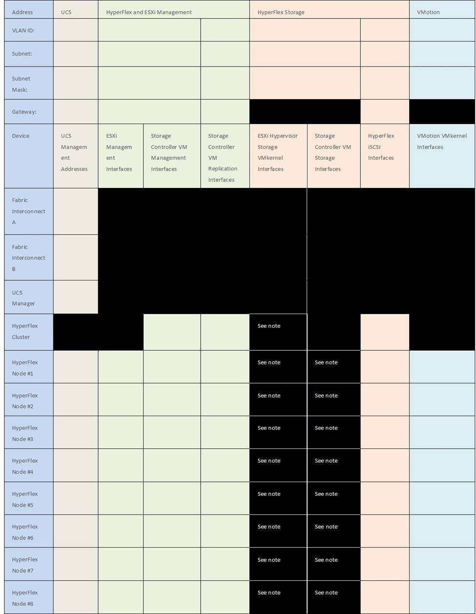
HyperFlex extended clusters are also addressed similarly to a standard cluster, they require additional IP addresses for Cisco UCS management, ESXi management, and Storage VMkernel interfaces for the additional compute-only nodes as shown below:
Table 14. HyperFlex Extended Cluster IP Addressing
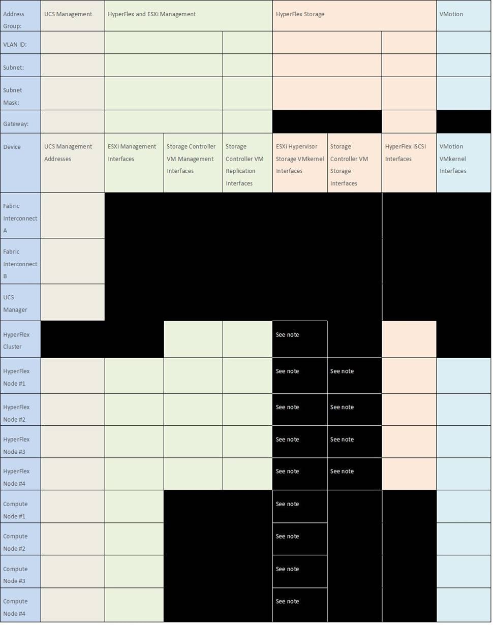
Table 15. HyperFlex Standard Cluster Example IP Addressing
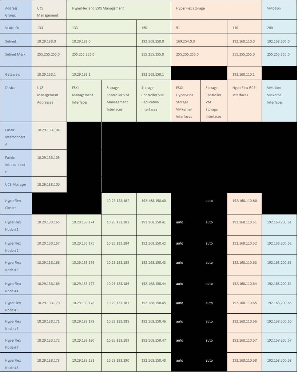
Note: IP addresses for Cisco UCS Management, plus HyperFlex and ESXi Management can come from the same subnet, or can be separate subnets, as long as the HyperFlex installer can reach them both.
By default, the HX installation will assign a static IP address to the management interface of the ESXi servers. Using Dynamic Host Configuration Protocol (DHCP) for automatic IP address assignment in not recommended.
DNS servers are highly recommended to be configured for querying Fully Qualified Domain Names (FQDN) in the HyperFlex and ESXi Management group. DNS records need to be created prior to beginning the installation. At a minimum, it is highly recommended to create A records and reverse PTR records for the ESXi hypervisor hosts’ management interfaces. Additional DNS A records can be created for the Storage Controller Management interfaces, ESXi Hypervisor Storage interfaces, and the Storage Controller Storage interfaces if desired.
Using the following tables, gather the required DNS information for the installation, by listing the information required, and an example configuration.
Table 16. DNS Server Information
| Item |
Value |
| DNS Server #1 |
|
| DNS Server #2 |
|
| DNS Domain |
|
| vCenter Server Name |
|
| SMTP Server Name |
|
| UCS Domain Name |
|
| HX Server #1 Name |
|
| HX Server #2 Name |
|
| HX Server #3 Name |
|
| HX Server #4 Name |
|
| HX Server #5 Name |
|
| HX Server #6 Name |
|
| HX Server #7 Name |
|
| HX Server #8 Name |
|
Table 17. DNS Server Example Information
| Item |
Value |
| DNS Server #1 |
10.29.133.110 |
| DNS Server #2 |
|
| DNS Domain |
hx.lab.cisco.com |
| vCenter Server Name |
vcenter.hx.lab.cisco.com |
| SMTP Server Name |
outbound.cisco.com |
| UCS Domain Name |
HX1-FI |
| HX Server #1 Name |
hxaf220m6n-01.hx.lab.cisco.com |
| HX Server #2 Name |
hxaf220m6n-02.hx.lab.cisco.com |
| HX Server #3 Name |
hxaf220m6n-03.hx.lab.cisco.com |
| HX Server #4 Name |
hxaf220m6n-04.hx.lab.cisco.com |
| HX Server #5 Name |
hxaf220m6n-05.hx.lab.cisco.com |
| HX Server #6 Name |
hxaf220m6n-06.hx.lab.cisco.com |
| HX Server #7 Name |
hxaf220m6n-07.hx.lab.cisco.com |
| HX Server #8 Name |
hxaf220m6n-08.hx.lab.cisco.com |
Consistent time clock synchronization is required across the components of the HyperFlex system, provided by reliable NTP servers, accessible for querying in the Cisco UCS Management network group, and the HyperFlex and ESXi Management group. NTP is used by Cisco UCS Manager, vCenter, the ESXi hypervisor hosts, and the HyperFlex Storage Platform Controller VMs. The use of public NTP servers is highly discouraged, instead a reliable internal NTP server should be used.
Using the following tables, gather the required NTP information for the installation by listing the information required, and an example configuration.
Table 18. NTP Server Information
| Item |
Value |
| NTP Server #1 |
|
| NTP Server #2 |
|
| Timezone |
|
Table 19. NTP Server Example Information
| Item |
Value |
| NTP Server #1 |
ntp1.hx.lab.cisco.com |
| NTP Server #2 |
ntp2.hx.lab.cisco.com |
| Timezone |
(UTC-8:00) Pacific Time |
Prior to the installation, the required VLAN IDs need to be documented, and created in the upstream network if necessary. At a minimum, there are 4 VLANs that need to be trunked to the Cisco UCS Fabric Interconnects that comprise the HyperFlex system; a VLAN for the HyperFlex and ESXi Management group, a VLAN for the HyperFlex Storage group, a VLAN for the VMotion group, and at least one VLAN for the guest VM traffic. If HyperFlex Replication is to be used, another VLAN must be created and trunked for the replication traffic. If inbound iSCSI storage presentation is going to be used, then another VLAN must be created for that traffic. Finally, if outbound iSCSI connections will be made to external storage via the optional additional pair of vNICs, those two VLAN must also be created. The VLAN names and IDs must be supplied during the HyperFlex installation wizard.
Using the following tables, gather the required VLAN information for the installation by listing the information required, and an example configuration.
| Name |
ID |
| <<hx-inband-mgmt>> |
|
| <<hx-inband-repl>> |
|
| <<hx-storage-data>> |
|
| <<hx-inband-iscsi>> |
|
| <<hx-ext-iscsi-a>> |
|
| <<hx-ext-iscsi-b>> |
|
| <<hx-vm-data>> |
|
| <<hx-vmotion>> |
|
Table 21. VLAN Example Information
| Name |
ID |
| hx-mgmt-133 |
133 |
| hx-repl-150 |
150 |
| hx-storage |
51 |
| hx-inband-iscsi |
110 |
| iscsi-120 |
120 |
| iscsi-121 |
121 |
| vm-network-100 |
100 |
| vmotion-200 |
200 |
The Cisco UCS uplink connectivity design needs to be finalized prior to beginning the installation. One of the early manual tasks to be completed is to configure the Cisco UCS network uplinks and verify their operation, prior to beginning the HyperFlex installation steps. Refer to the network uplink design possibilities in the Network Design section. Cisco recommends that the uplink bandwidth configured is greater than or equal to double the bandwidth available to each Hyperflex converged node. For example, if the nodes are connected at 10 Gigabit speeds, then each Fabric Interconnect should have at least 20 Gigabit of uplink bandwidth available.
Using the following tables, gather the required network uplink information for the installation by listing the information required, and an example configuration.
Table 22. Network Uplink Configuration
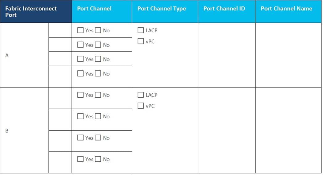
Table 23. Network Uplink Example Configuration

Several usernames and passwords need to be defined or known as part of the HyperFlex installation process. Using the following tables, gather the required username and password information by listing the information required and an example configuration.
Table 24. Example Usernames and Passwords
| Account |
Username |
Password |
| HX Installer Administrator |
root |
<<hx_install_root_pw>> |
| UCS Administrator |
admin |
<<ucs_admin_pw>> |
| ESXi Administrator |
root |
<<esxi_root_pw>> |
| HyperFlex Administrator |
admin |
<<hx_admin_pw>> |
| vCenter Administrator |
administrator@vsphere.local |
<<vcenter_admin_pw>> |
| Account |
Username |
Password |
| HX Installer Administrator |
root |
Cisco123 |
| UCS Administrator |
admin |
Cisco123 |
| ESXi Administrator |
root |
CIsco123!! |
| HyperFlex Administrator |
admin |
CIsco123!! |
| vCenter Administrator |
administrator@vsphere.local |
!Q2w3e4r |
Prior to the installation of Cisco HyperFlex, the Cisco UCS Fabric Interconnects and servers must be physically installed, cabled, and powered on. The Fabric Interconnects must receive their initial configuration before logging in to Cisco UCS Manager. In Cisco UCS Manager, the uplinks to the network are established, the servers are discovered, and finally the UCS domain is connected to the cloud-based Cisco Intersight management platform, or an on-premises Cisco Intersight appliance. Once the Cisco UCS domain is claimed by Cisco Intersight, the installation of Cisco HyperFlex can proceed.
Install the fabric interconnects, the HX-Series rack-mount servers, plus any additional standard C-series rack-mount servers, Cisco UCS 5108 chassis, Cisco UCS Fabric Extenders, and Cisco UCS blades according to their corresponding hardware installation guides listed below.
Cisco UCS 6400 Series Fabric Interconnect: https://www.cisco.com/c/en/us/td/docs/unified_computing/ucs/hw/6454-install-guide/6454.html
Cisco HX220c M6 Server: https://www.cisco.com/c/en/us/td/docs/hyperconverged_systems/HX_series/HX220c-M6/b-hx220c-m6.html
Cisco HX240c M6 Server: https://www.cisco.com/c/en/us/td/docs/hyperconverged_systems/HX_series/HX240c-M6/b-HX240c-M6.html
Cisco HX225c M6 Server: https://www.cisco.com/c/en/us/td/docs/hyperconverged_systems/HX_series/HX225c-M6/b-hx-c225-m6-node-installation-guide.html
Cisco HX245c M6 Server: https://www.cisco.com/c/en/us/td/docs/hyperconverged_systems/HX_series/HX245c-M6/b-HX245c-M6.html
Cisco UCS 5108 Chassis, Servers, and Fabric Extenders: http://www.cisco.com/c/en/us/td/docs/unified_computing/ucs/hw/chassis-install-guide/ucs5108_install.pdf
The physical layout of the Cisco HyperFlex system is described in the Physical Topology section. The fabric interconnects, HX-series rack-mount servers, Cisco UCS chassis and blades need to be cabled properly before beginning the installation activities.
Table 25 lists an example cabling map for installation of a Cisco HyperFlex system, with eight Cisco HyperFlex converged servers, and one Cisco UCS 5108 chassis.
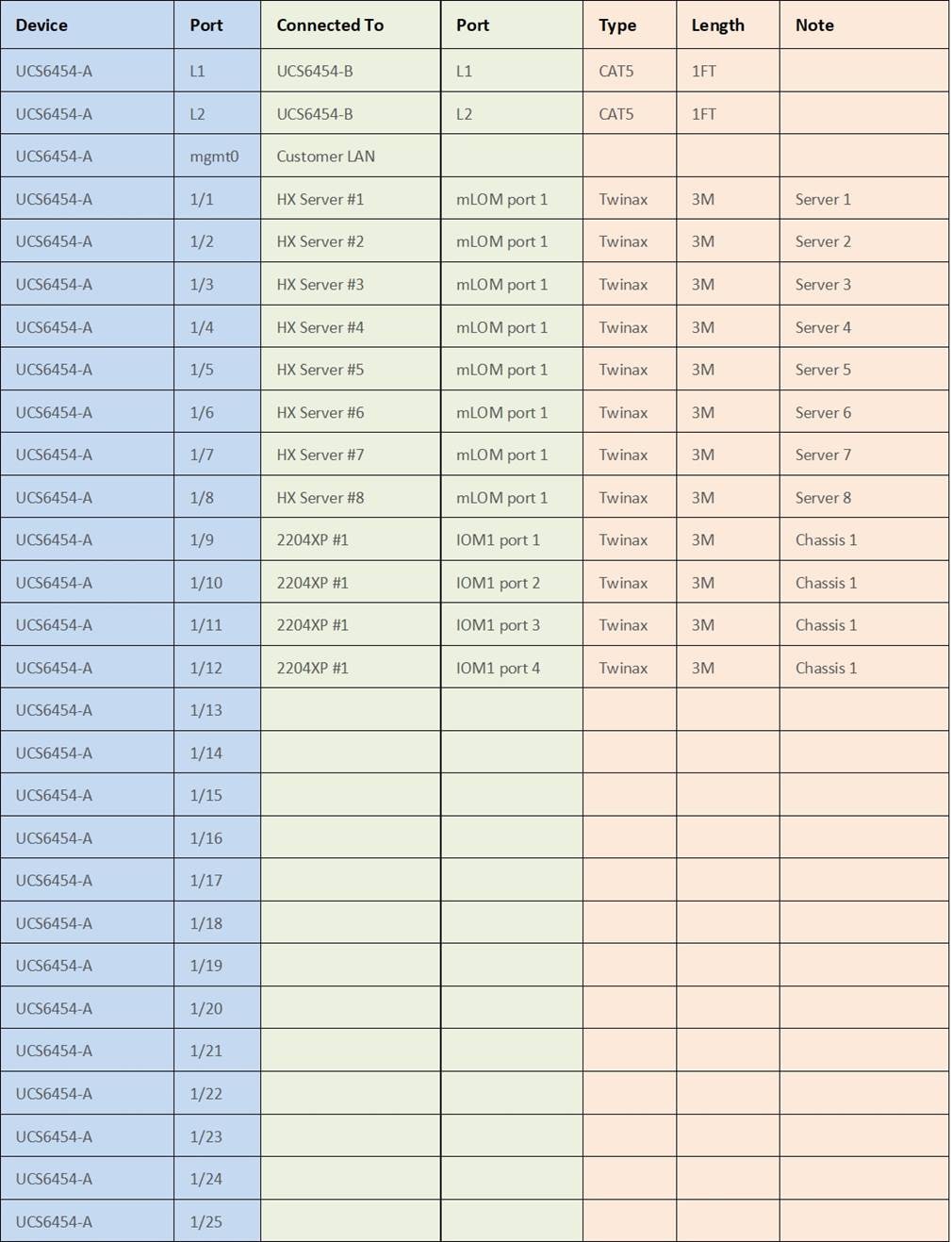
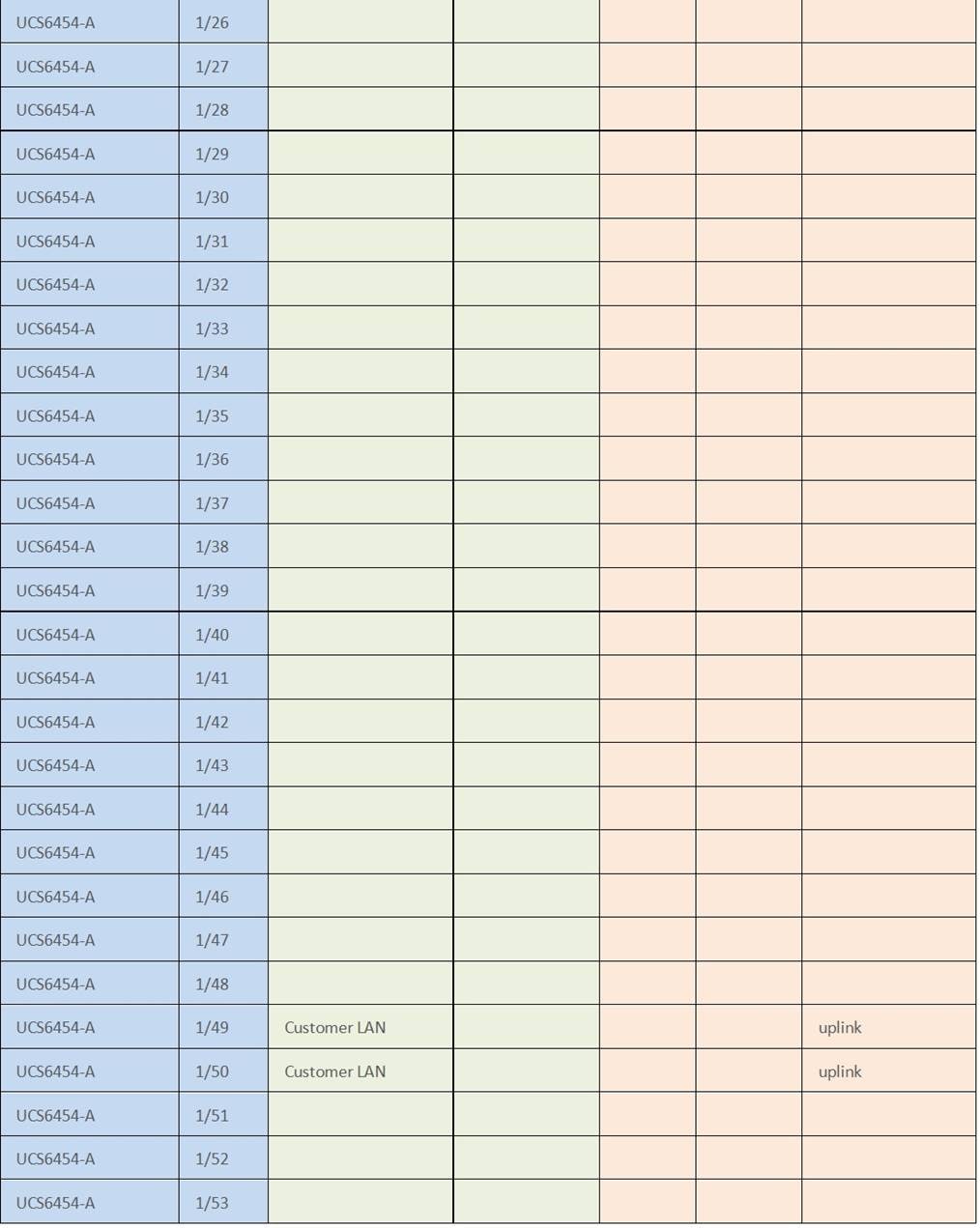
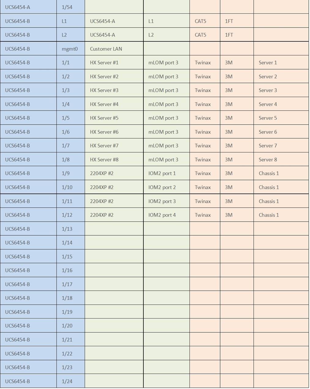
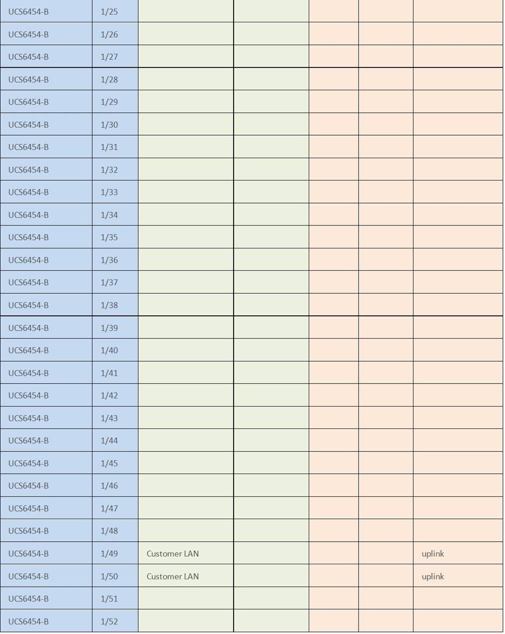

Cisco UCS Fabric Interconnect A
This section describes the steps to initialize and configure the Cisco UCS Fabric Interconnects, to prepare them for the Cisco HyperFlex installation. In the first procedure the first fabric interconnect is configured with its basic networking information.
Procedure 1. Configure Fabric Interconnect A
Step 1. Make sure the Fabric Interconnect cabling is properly connected, including the L1 and L2 cluster links, and power the Fabric Interconnects on by inserting the power cords.
Step 2. Connect to the console port on the first fabric interconnect, which will be designated as the A fabric device. Use the supplied Cisco console cable (CAB-CONSOLE-RJ45=), and connect it to a built-in DB9 serial port, or use a USB to DB9 serial port adapter.
Step 3. Start your terminal emulator software.
Step 4. Create a connection to the COM port of the computer’s DB9 port, or the USB to serial adapter. Set the terminal emulation to VT100, and the settings to 9600 baud, 8 data bits, no parity, and 1 stop bit.
Step 5. Open the connection just created. You may have to press ENTER to see the first prompt.
Step 6. Configure the first Fabric Interconnect, using the following example as a guideline:
---- Basic System Configuration Dialog ----
This setup utility will guide you through the basic configuration of
the system. Only minimal configuration including IP connectivity to
the Fabric interconnect and its clustering mode is performed through these steps.
Type Ctrl-C at any time to abort configuration and reboot system.
To back track or make modifications to already entered values,
complete input till end of section and answer no when prompted
to apply configuration.
Enter the configuration method. (console/gui) ? console
Enter the setup mode; setup newly or restore from backup. (setup/restore) ? setup
You have chosen to setup a new Fabric interconnect. Continue? (y/n): y
Enforce strong password? (y/n) [y]: y
Enter the password for "admin":
Confirm the password for "admin":
Is this Fabric interconnect part of a cluster(select 'no' for standalone)? (yes/no) [n]: yes
Enter the switch fabric (A/B) []: A
Enter the system name: HX1-FI
Physical Switch Mgmt0 IP address : 10.29.133.104
Physical Switch Mgmt0 IPv4 netmask : 255.255.255.0
IPv4 address of the default gateway : 10.29.133.1
Cluster IPv4 address : 10.29.133.106
Configure the DNS Server IP address? (yes/no) [n]: yes
DNS IP address : 10.29.133.110
Configure the default domain name? (yes/no) [n]: yes
Default domain name : hx.lab.cisco.com
Join centralized management environment (UCS Central)? (yes/no) [n]: no
Following configurations will be applied:
Switch Fabric=A
System Name=HX1-FI
Enforced Strong Password=no
Physical Switch Mgmt0 IP Address=10.29.133.104
Physical Switch Mgmt0 IP Netmask=255.255.255.0
Default Gateway=10.29.133.1
Ipv6 value=0
DNS Server=10.29.133.110
Domain Name=hx.lab.cisco.com
Cluster Enabled=yes
Cluster IP Address=10.29.133.106
NOTE: Cluster IP will be configured only after both Fabric Interconnects are initialized
Apply and save the configuration (select 'no' if you want to re-enter)? (yes/no): yes
Applying configuration. Please wait.
Configuration file - Ok
Cisco UCS Fabric Interconnect B
In this procedure, the second fabric interconnect is given its IP address and joined to the first Fabric Interconnect to form a UCS domain cluster.
Procedure 1. Configure Fabric Interconnect B
Step 1. Connect to the console port on the first fabric interconnect, which will be designated as the B fabric device. Use the supplied Cisco console cable (CAB-CONSOLE-RJ45=), and connect it to a built-in DB9 serial port, or use a USB to DB9 serial port adapter.
Step 2. Start your terminal emulator software.
Step 3. Create a connection to the COM port of the computer’s DB9 port, or the USB to serial adapter. Set the terminal emulation to VT100, and the settings to 9600 baud, 8 data bits, no parity, and 1 stop bit.
Step 4. Open the connection just created. You may have to press ENTER to see the first prompt.
Step 5. Configure the second Fabric Interconnect, using the following example as a guideline:
---- Basic System Configuration Dialog ----
This setup utility will guide you through the basic configuration of
the system. Only minimal configuration including IP connectivity to
the Fabric interconnect and its clustering mode is performed through these steps.
Type Ctrl-C at any time to abort configuration and reboot system.
To back track or make modifications to already entered values,
complete input till end of section and answer no when prompted
to apply configuration.
Enter the configuration method. (console/gui) ? console
Installer has detected the presence of a peer Fabric interconnect. This Fabric interconnect will be added to the cluster. Continue (y/n) ? y
Enter the admin password of the peer Fabric interconnect:
Connecting to peer Fabric interconnect... done
Retrieving config from peer Fabric interconnect... done
Peer Fabric interconnect Mgmt0 IPv4 Address: 10.29.133.104
Peer Fabric interconnect Mgmt0 IPv4 Netmask: 255.255.255.0
Cluster IPv4 address : 10.29.133.106
Peer FI is IPv4 Cluster enabled. Please Provide Local Fabric Interconnect Mgmt0 IPv4 Address
Physical Switch Mgmt0 IP address : 10.29.133.105
Apply and save the configuration (select 'no' if you want to re-enter)? (yes/no): yes
Applying configuration. Please wait.
Configuration file – Ok
After a few minutes, the Cisco UCS Manager web console will be available. Use Cisco UCS Manager to complete the following procedures.
Procedure 1. Log in to the Cisco UCS Manager environment
Step 1. Open a web browser and navigate to the Cisco UCS Manager Cluster IP address, for example https://10.29.133.106
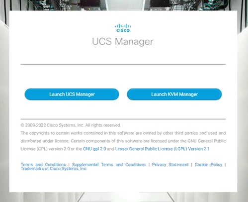
Step 2. Click the “Launch UCS Manager” HTML link to open the Cisco UCS Manager web client.
Step 3. At the login prompt, enter “admin” as the username, and enter the administrative password that was set during the initial console configuration.
Step 4. Click No when prompted to enable Cisco Smart Call Home, this feature can be enabled at a later time.
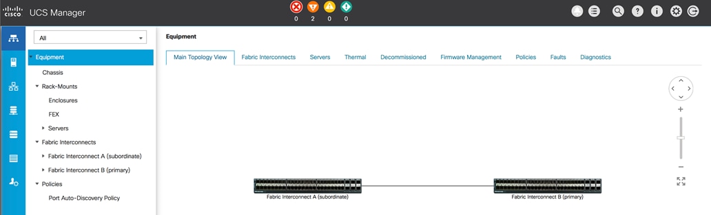
Configure the following ports, settings, and policies in the Cisco UCS Manager interface prior to beginning the Cisco HyperFlex installation.
Your Cisco UCS firmware version should be correct as shipped from the factory, as documented in the Software Components section. This document is based on Cisco UCS infrastructure, Cisco UCS B-series bundle, and Cisco UCS C-Series bundle software versions 4.2(2c). If the firmware version of the Fabric Interconnects is older than this version, the firmware must be upgraded to match the requirements prior to completing any further steps. To upgrade the Cisco UCS Manager version, the Fabric Interconnect firmware, and the server bundles, refer to these instructions: https://www.cisco.com/c/en/us/td/docs/unified_computing/ucs/ucs-manager/GUI-User-Guides/Firmware-Mgmt/4-2/b_UCSM_GUI_Firmware_Management_Guide_4-2.html
In this procedure, the Cisco UCS domain is configured to synchronize its time with an authoritative network time source.
Procedure 1. Synchronize the Cisco UCS environment time to the NTP server
Step 1. In Cisco UCS Manager, click the Admin button on the left-hand side.
Step 2. In the navigation pane, select All > Time Zone Management, and click the carat next to Time Zone Management to expand it.
Step 3. Click Timezone.
Step 4. In the Properties pane, select the appropriate time zone in the Time Zone menu.
Step 5. Click Add NTP Server.
Step 6. Enter the NTP server IP address and click OK.
Step 7. Click OK.
Step 8. Click Save Changes and then click OK.
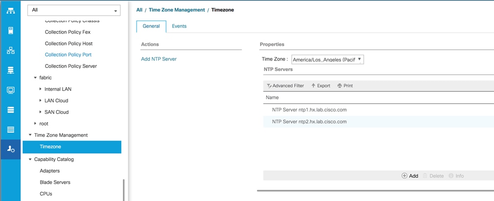
The Ethernet ports of a Cisco UCS Fabric Interconnect are all capable of performing several functions, such as network uplinks or server ports, and more. By default, all ports are unconfigured, and their function must be defined by the administrator. In this procedure the ports to be used as network uplinks are set with the appropriate role.
Procedure 1. Define the specified ports to be used as network uplinks
Step 1. In Cisco UCS Manager, click the Equipment button on the left-hand side.
Step 2. Select Fabric Interconnects > Fabric Interconnect A > Fixed Module or Expansion Module as appropriate > Ethernet Ports.
Step 3. Select the ports that are to be uplink ports, right click them, and click Configure as Uplink Port.
Step 4. Click Yes to confirm the configuration, then click OK.
Step 5. Select Fabric Interconnects > Fabric Interconnect B > Fixed Module or Expansion Module as appropriate > Ethernet Ports.
Step 6. Select the ports that are to be uplink ports, right-click them, and click Configure as Uplink Port.
Step 7. Click Yes to confirm the configuration and click OK.
Step 8. Verify all the necessary ports are now configured as uplink ports, where their role is listed as “Network.”
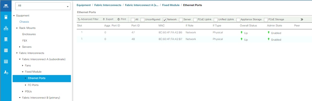
If the Cisco UCS uplinks from one Fabric Interconnect are to be combined into a port channel or vPC, you must separately configure the port channels, which will use the previously configured uplink ports. In this procedure, the network uplink ports of each Fabric Interconnect are grouped into port channels.
Procedure 1. Configure the necessary port channels in the Cisco UCS environment
Step 1. In Cisco UCS Manager, click the LAN button on the left-hand side.
Step 2. Under LAN > LAN Cloud, click the carat to expand the Fabric A tree.
Step 3. Right-click Port Channels underneath Fabric A, then click Create Port Channel.
Step 4. Enter the port channel ID number as the unique ID of the port channel (this does not have to match the port-channel ID on the upstream switch).
Step 5. Enter the name of the port channel.
Step 6. Click Next.
Step 7. Click each port from Fabric Interconnect A that will participate in the port channel, then click the >> button to add them to the port channel.
Step 8. Click Finish.
Step 9. Click OK.
Step 10. Under LAN > LAN Cloud, click the carat to expand the Fabric B tree.
Step 11. Right-click Port Channels underneath Fabric B, then click Create Port Channel.
Step 12. Enter the port channel ID number as the unique ID of the port channel (this does not have to match the port-channel ID on the upstream switch).
Step 13. Enter the name of the port channel.
Step 14. Click Next.
Step 15. Click each port from Fabric Interconnect B that will participate in the port channel, then click the >> button to add them to the port channel.
Step 16. Click Finish.
Step 17. Click OK.
Step 18. Verify the necessary port channels have been created. It can take a few minutes for the newly formed port channels to converge and come online.
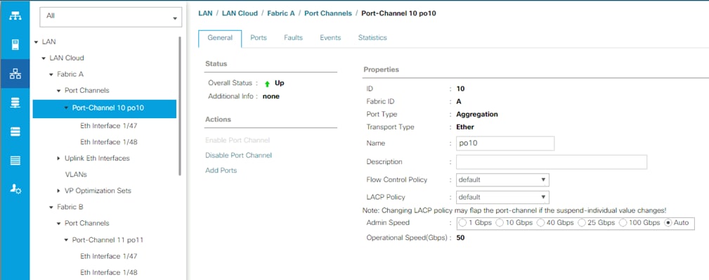
If the Cisco HyperFlex system will use blades as compute-only nodes in an extended cluster design, additional settings must be configured for connecting the Cisco UCS 5108 blade chassis. The Chassis Discovery policy defines the number of links between the Fabric Interconnect and the Cisco UCS Fabric Extenders which must be connected and active, before the chassis will be discovered. This also effectively defines how many of those connected links will be used for communication. The Link Grouping Preference setting specifies if the links will operate independently, or if Cisco UCS Manager will automatically combine them into port-channels. Cisco best practices recommends using link grouping, and the number of links per side is dependent on the hardware used in Cisco UCS 5108 chassis, and the model of Fabric Interconnects. For 10 GbE connections Cisco recommends 4 links per side, and for 40 GbE connections Cisco recommends 2 links per side.
Procedure 1. Configure the necessary policy and setting
Step 1. In Cisco UCS Manager, click the Equipment button on the left-hand side, and click Equipment in the top of the navigation tree on the left.
Step 2. In the properties pane, click the Policies tab.
Step 3. Under the Global Policies sub-tab, set the Chassis/FEX Discovery Policy to match the number of uplink ports that are cabled per side, between the chassis and the Fabric Interconnects.
Step 4. Set the Link Grouping Preference option to Port Channel.
Step 5. Set the backplane speed preference to 4x10 Gigabit or 40 Gigabit.
Step 6. Click Save Changes.
Step 7. Click OK.
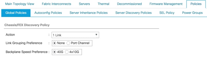
The Ethernet ports of a Cisco UCS Fabric Interconnect connected to the rack-mount servers, or to the blade chassis must be defined as server ports. When a server port is activated, the connected server or chassis will begin the discovery process shortly afterwards. Rack-mount servers and blade chassis are automatically numbered in Cisco UCS Manager in the order which they are first discovered. For this reason, it is important to configure the server ports sequentially in the order you wish the physical servers and/or chassis to appear within Cisco UCS Manager. For example, if you installed your servers in a cabinet or rack with server #1 on the bottom, counting up as you go higher in the cabinet or rack, then you need to enable the server ports to the bottom-most server first, and enable them one-by-one as you move upward. You must wait until the server appears in the Equipment tab of Cisco UCS Manager before configuring the ports for the next server. The same numbering procedure applies to blade server chassis, although chassis and rack-mount server numbers are separate from each other.
Auto Configuration
A new feature in Cisco UCS Manager 3.1(3a) and later is Server Port Auto-Discovery, which automates the configuration of ports on the Fabric Interconnects as server ports when a Cisco UCS rack-mount server or blade chassis is connected to them. The firmware on the rack-mount servers or blade chassis Fabric Extenders must already be at version 3.1(3a) or later in order for this feature to function properly. Enabling this policy eliminates the manual steps of configuring each server port, however it can configure the servers in a somewhat random order depending upon the circumstances. An example of how to use this feature in an orderly manner would be to have the policy already set, then to mount, cable and apply power to each new server one-by-one. In this scenario the servers should be automatically discovered in the order you racked them and applied power.
An example of how the policy can result in unexpected ordering would be when the policy has not been enabled, then all of the new servers are racked, cabled, and have power applied to them. If the policy is enabled afterwards, it will likely not discover the servers in a logical order. For example, the rack-mount server at the bottom of the stack, which you may refer to as server #1, and you may have plugged into port 1 of both Fabric Interconnects, could be discovered as server 2, or server 5, and so on. In order to have fine control of the rack-mount server or chassis numbering and order in this scenario, the manual configuration steps listed in the next section must be followed.
Procedure 1. Configure automatic server port definition and discovery
Step 1. In Cisco UCS Manager, click the Equipment button on the left-hand side.
Step 2. In the navigation tree, under Policies, click Port Auto-Discovery Policy.
Step 3. In the properties pane, set Auto Configure Server Port option to Enabled.
Step 4. Click Save Changes.
Step 5. Click OK.
Step 6. Wait for a brief period, until the rack-mount servers appear in the Equipment tab underneath Equipment > Rack Mounts > Servers, or the chassis appears underneath Equipment > Chassis.
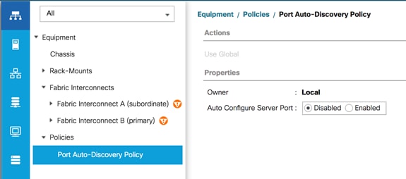
Manual Configuration
In this procedure, the ports to be used as server ports are manually defined, in order to have control over the numbering of the servers.
Procedure 1. Manually configure the server ports
Step 1. In Cisco UCS Manager, click the Equipment button on the left-hand side.
Step 2. Select Fabric Interconnects > Fabric Interconnect A > Fixed Module or Expansion Module as appropriate > Ethernet Ports.
Step 3. Select the first port that is to be a server port, right-click it, and click Configure as Server Port.
Step 4. Click Yes to confirm the configuration and click OK.
Step 5. Select Fabric Interconnects > Fabric Interconnect B > Fixed Module or Expansion Module as appropriate > Ethernet Ports.
Step 6. Select the matching port as chosen for Fabric Interconnect A that is to be a server port, right-click it, and click Configure as Server Port.
Step 7. Click Yes to confirm the configuration and click OK.
Step 8. Wait for a brief period, until the rack-mount server appears in the Equipment tab underneath Equipment > Rack Mounts > Servers, or the chassis appears underneath Equipment > Chassis.
Step 9. Repeat steps 1-8 for each pair of server ports, until all rack-mount servers and chassis appear in the order desired in the Equipment tab.
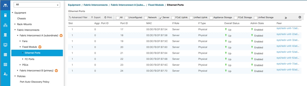
As previously described, when the server ports of the Fabric Interconnects are configured and active, the servers connected to those ports will begin a discovery process. During discovery, the servers’ internal hardware inventories are collected, along with their current firmware revisions. Before continuing with the Cisco HyperFlex installation, which will create the service profiles and associate them with the servers, wait for all of the servers to finish their discovery processes and to show as unassociated servers that are powered off, with no errors.
Procedure 1. View the servers’ discovery status
Step 1. In Cisco UCS Manager, click the Equipment button on the left-hand side, and click Equipment in the top of the navigation tree on the left.
Step 2. In the properties pane, click the Servers tab.
Step 3. Click the Blade Servers or Rack-Mount Servers sub-tab as appropriate, then view the servers’ status in the Overall Status column.
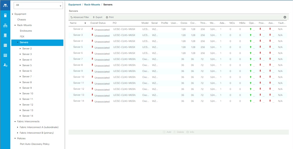
Cisco Intersight Account
A Cisco Intersight account is required for this solution. To create your Intersight account you must have a valid Cisco ID first. If you do not have a Cisco ID, this procedure will guide you through the creation of an account.
Procedure 1. Create a Cisco ID online
Step 1. Visit https://intersight.com from your workstation.
Step 2. Click “Sign In with Cisco ID.”
Step 3. On the Cisco Login page, you have the option to log into an Existing Account or click Sign Up to create a new account.
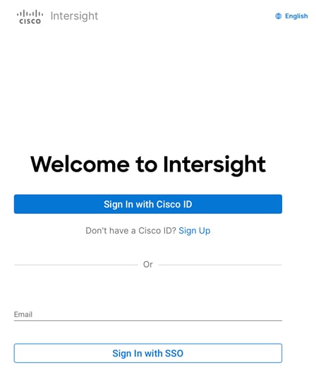
Step 4. Click Sign Up and provide the requested information to create a cisco.com account.
Step 5. Once a valid account is created, it can be used to log into Cisco Intersight.
Consider the following prerequisites pertaining to Cisco Intersight connectivity:
● Before installing the HX cluster on a set of HX servers, make sure that the device connector of the corresponding Cisco UCS domain is properly configured to connect to Cisco Intersight and claimed.
● All device connectors must properly resolve svc.intersight.com and allow outbound initiated HTTPS connections on port 443. The current version of the HX Installer supports the use of an HTTP proxy.
● All controller VM management interfaces must properly resolve svc.intersight.com and allow outbound initiated HTTPS connections on port 443. The current version of HX Installer supports the use of an HTTP proxy if direct Internet connectivity is unavailable.
● IP connectivity (L2 or L3) is required from the CIMC management IP on each server to all of the following: ESXi management interfaces, HyperFlex controller VM management interfaces, and vCenter server. Any firewalls in this path should be configured to allow the necessary ports as outlined in the Hyperflex Hardening Guide: https://www.cisco.com/c/dam/en/us/support/docs/hyperconverged-infrastructure/hyperflex-hx-data-platform/HX-Hardening_Guide.pdf
● When redeploying Cisco HyperFlex on the same servers, new controller VMs must be downloaded from Intersight into all ESXi hosts. This requires each ESXi host to be able to resolve svc.intersight.com and allow outbound initiated HTTPS connections on port 443. Use of a proxy server for controller VM downloads is supported and can be configured in the HyperFlex Cluster Profile if desired.
● Post-cluster deployment, the new HyperFlex cluster is automatically claimed in Cisco Intersight for ongoing management.
Claim Devices in Cisco Intersight
The Cisco UCS Manager device connector allows Cisco Intersight to manage the Cisco UCS domain and all of the connected HyperFlex servers and claim them for cloud management. This procedure describes how to claim a UCS domain in Cisco Intersight for management, monitoring, and for the later installation of Cisco HyperFlex.
Procedure 1. Claim devices in Cisco Intersight
Step 1. Log into the Cisco UCS Manager web interface of the Cisco Fabric Interconnects which are connected to the Cisco HX-series servers that will comprise the new Cisco HyperFlex cluster being installed.
Step 2. From the left-hand navigation pane click Admin, then click Device Connector.
Step 3. Note that the Cisco UCS domain shows a status of “Not Claimed.” Copy the Device ID and the Claim Code by clicking the small clipboard icons.
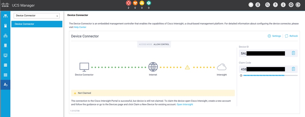
Step 4. Open a web browser and navigate to the Cisco Intersight Cloud Management platform https://intersight.com/.
Step 5. Login with your Cisco ID and password. If this is the first time using Intersight, it is recommended you take a site tour to be guided through some main features.
Step 6. To Claim a new device, from the services menu at the top of the screen, select System, then from the navigation menu on the left, expand Administration, then click Targets. In the Targets window, select Claim a New Target in the upper right corner.
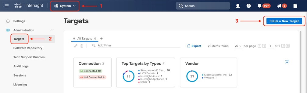
Step 7. Select the target type named Cisco UCS Domain (UCSM Managed), then click Start.
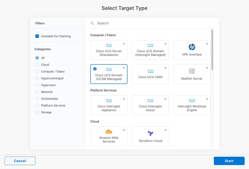
Step 8. Enter the Device ID and Claim Code obtained from Cisco UCS Manager GUI. Use copy and paste for accuracy. If necessary, select a resource Group to add this UCS domain to from the list, then click Claim.
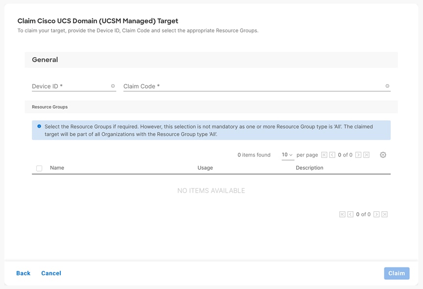
Step 9. In the Targets window, the Cisco UCS Fabric Interconnect domain should now show as claimed devices.
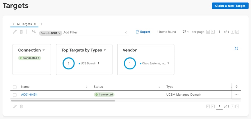
Step 10. Click the Refresh link in the Cisco UCS Manager Device Connector screen. The Device Connector now shows this device is claimed.
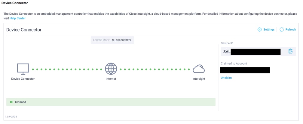
Cisco Intersight provides an installation wizard to install, configure, and deploy Cisco HyperFlex clusters. The wizard constructs a pre-configuration definition of a Cisco HyperFlex cluster called an HX Cluster Profile. The cluster profile is policy driven with administrator-defined sets of rules and operating characteristics such as the node identity, interfaces, and vCenter connectivity. Every active node in the Cisco HyperFlex cluster must be associated with an HX Cluster Profile. After the user inputs all configuration settings, the installation wizard will validate and deploy the HX Cluster Profile on the Cisco HX-series nodes. You can clone a successfully deployed HX Cluster Profile, and then use that copy as the basis to easily create many more new clusters.
Procedure 1. Install and configure a Cisco HyperFlex standard cluster with Cisco Intersight
Step 1. Login to Cisco Intersight Cloud Management platform https://intersight.com/ with your Cisco ID and password.
Step 2. From the services menu at the top of the screen, select Infrastructure Service, then from the navigation menu on the left, expand Configure, then click Profiles. In the Profiles window, select the HyperFlex Cluster Profiles tab, then select Create HyperFlex Cluster Profile in the upper right corner.
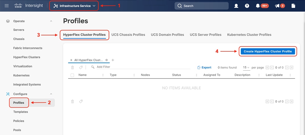
Step 3. The HyperFlex Cluster Profile installation wizard is displayed. On the first page you must choose between installing a datacenter or edge cluster, and whether to use Fabric Interconnects or not. For this standard datacenter cluster, select Data Center, leave the box for Use Fabric Interconnect checked, then click Start.
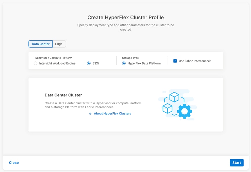
Step 4. On the General page, select the Intersight Organization as appropriate and enter a cluster name under Name. This cluster name must be unique and will be used as the HXDP cluster name, vCenter cluster name, Intersight cluster name, and the name of the Org created in Cisco UCS Manager (this Org in Cisco UCS Manager is not the same as the Intersight Organization). Select the appropriate HXDP version, then select the required Server Firmware Version. Afterwards, add any desired description or tags for this cluster for good reference, then click Next.
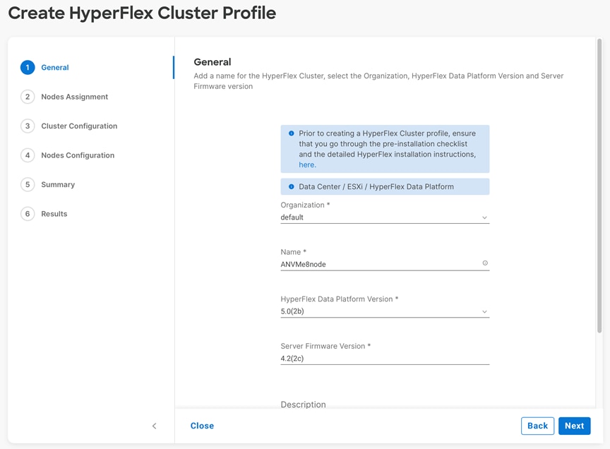
Step 5. The next section allows you to choose which servers in the UCS domain will be assigned to this cluster. Servers can be searched for or filtered by name, model number or serial number. If desired, the radio button for Assign Nodes Later can be clicked in order to complete this step at a later time. Check the box to the left of each server to assign to this cluster, then click Next.
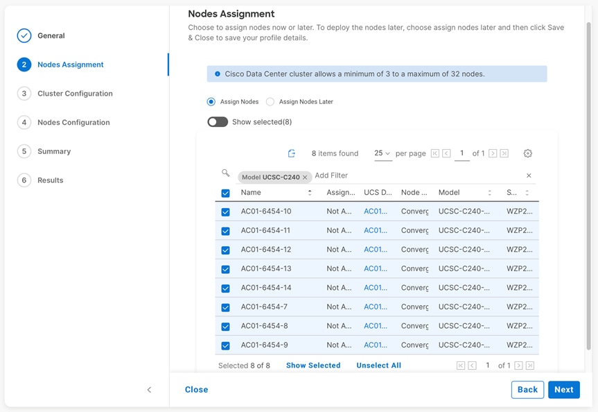
Step 6. In the next section the policies are created to be used as part of the HyperFlex Cluster Profile. At any time, it is possible to click Close to save this cluster profile configuration and then return to complete the work at a later time.
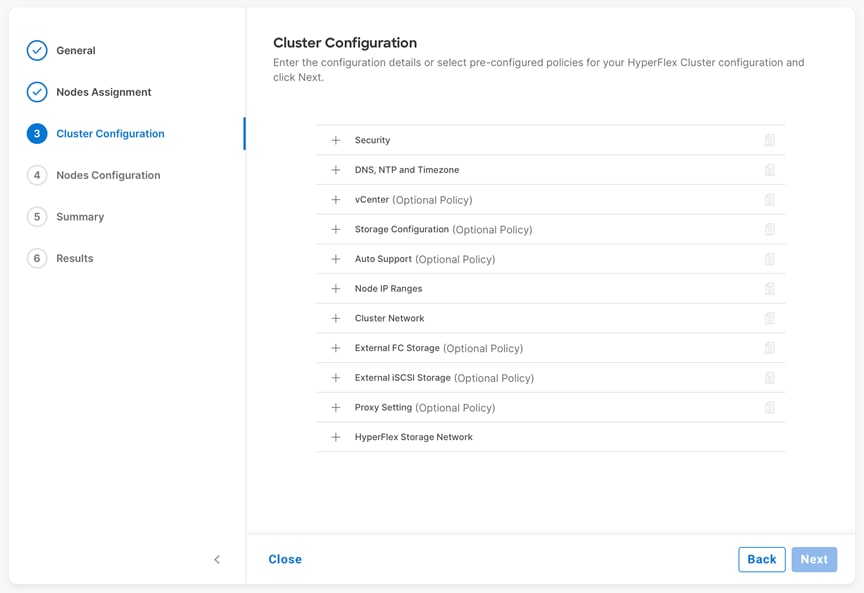
Step 7. Click + to expand Security configuration. Enter root as the Hypervisor administrative user. Click the check box if the hypervisor on this node uses the factory default password. Input a new user supplied password for the root account of the Hypervisor and a user supplied password for the HX controller VM. Once you close the security configuration by collapsing the section via clicking on the minus (“-“) symbol, or clicking on another section below, the settings are automatically saved to a policy named <HX-Cluster-Name>-local-credential-policy. This policy is reusable and can be selected for use when you create your next HX Cluster Profile.
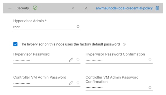
Step 8. (Optional) To choose an existing policy for one section of the cluster profile, at the policy line, click Select Policy icon, to choose the desired policy from the available policy list and click Select.

Step 9. Click + to expand DNS, NTP and Timezone configuration. Choose a time zone from the drop-down list, then enter the DNS server and NTP server information. Click + to add secondary DNS or NTP servers. Once you close the DNS, NTP, and Timezone configuration, the settings are automatically saved to a reusable policy named <HX-Cluster-Name>-sys-config-policy.
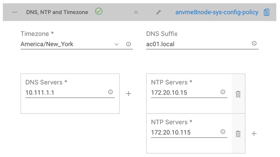
Step 10. Click + to expand vCenter configuration. Enter the vCenter server FQDN or IP address, and an administrative username and password. Enter the Datacenter name in vCenter hosting the HX Edge cluster. The Datacenter name can match an existing datacenter object in the vCenter environment, if it does not match an existing object a new Datacenter will be created with the name supplied. Once you close the vCenter configuration, the settings are automatically saved to a reusable policy named <HX-Cluster-Name>-vcenter-config-policy.
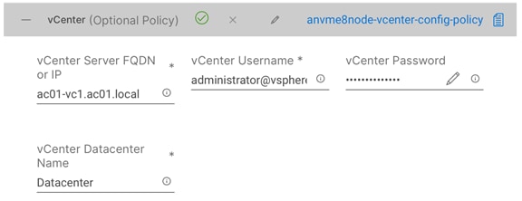
Step 11. Click + to expand Storage Configuration. If deploying a VDI environment on a hybrid HX cluster, check the box to enable filesystem optimizations. If deploying a cluster of 8 nodes or more, check the box to enable Logical Availability Zones if desired. Once you close the Storage configuration, the settings are automatically saved to a reusable policy named <HX-Cluster-Name>-cluster-storage-policy.
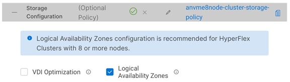
Step 12. Click + to expand Auto Support configuration. Check the box to enable Auto-Support. Enter your email address for the service ticket notifications. Once you close the Auto Support configuration, the settings are automatically saved to a reusable policy named <HX-Cluster-Name>-auto-support-policy.
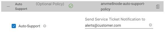
Step 13. Click + to expand Node IP Ranges. Enter a starting IP address, an ending IP address, the subnet mask, and gateway for the management IP pool. IPs from this range will be automatically assigned to the ESXi hosts’ management interfaces during the node configuration step.
Step 14. If only the management network IPs are entered, the same range will be used for both ESXi management and HX Controller VM management IPs. If you desire to use a second, non-contiguous range of IPs for the HX Controller VMs, you may optionally enter starting and ending IP addresses, subnet mask and gateway for the HX Controller VM management IP pool. Note these two IP ranges must fall within the same IP subnet and VLAN. Once you close the IP & Hostname configuration, the settings are automatically saved to a reusable named <HX-Cluster-Name>-node-config-policy.
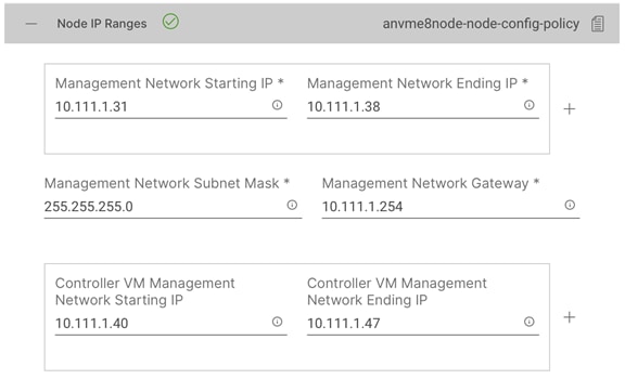
Step 15. Click + to expand Cluster Network. Enter a VLAN name and ID which will be used for management of the Cisco HyperFlex cluster, such as the ESXi hosts and the controller VMs. This name and ID will be created in UCS Manager by the installer.
Step 16. Enter the VLAN name and ID for the VM Migration VLAN which will be used for vMotion. This name and ID will be created in UCS Manager by the installer.
Step 17. Enter the VLAN name and ID which will be used for the guest VMs. Click the + button to add more guest VM VLANs if necessary. These names and IDs will be created in UCS Manager by the installer.
Step 18. Enter the starting and ending IP addresses for the UCS management IP pool to be assigned to the HX-series nodes, and the subnet mask and gateway. These IP addresses must be in the same VLAN as the management interfaces of the Fabric Interconnects.
Step 19. Lastly, check the box to enable Jumbo Frames. Cisco highly recommends using Jumbo frames in all standard HyperFlex environments, unless the upstream switches connected to the fabric interconnects cannot be configured to carry jumbo frames across the uplinks. Once you close the Network configuration, the settings are automatically saved to a reusable policy named <HX-Cluster-Name>-cluster-network-policy.
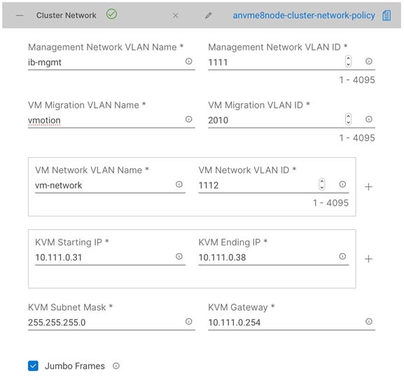
Step 20. (Optional) Click + to expand External FC Storage. Check the box to Enable FC storage, which will create a pair of vHBAs in the UCS Service Profiles for the HX nodes. Enter the VSAN names and IDs for the A and B sides of the fabric. Enter the 6th byte value for the starting and ending World-Wide Names that will be assigned to the nodes and ports in the FC fabric. Once you close the External FC Storage configuration, the settings are automatically saved to a reusable policy named <HX-Cluster-Name>-ext-fc-storage-policy.
Step 21. (Optional) Click + to expand External iSCSI Storage. Check the box to Enable iSCSI storage, which will create an additional pair of vNICs in the UCS Service Profiles for the HX nodes and configure them to carry the iSCSI VLANs you define in this section. Enter the iSCSI VLAN names and IDs for the A and B sides of the fabric. Once you close the External iSCSI Storage configuration, the settings are automatically saved to a reusable policy named <HX-Cluster-Name>-ext-iscsi-storage-policy.
Step 22. If necessary, click + to expand Proxy Setting. Enter the Proxy server hostname, port, username, and password.
Step 23. Click + to expand HyperFlex Storage Network configuration. Enter the VLAN name and ID for the HyperFlex data storage network. It is highly recommended to use a unique storage VLAN per cluster if multiple clusters are to be deployed within the same network. To avoid possible conflicts this policy is not saved for reuse.
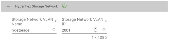
Step 24. Now that all the policies are configured, the saved or selected policies will be listed in this page. Click Next to proceed to the Nodes Configuration page.
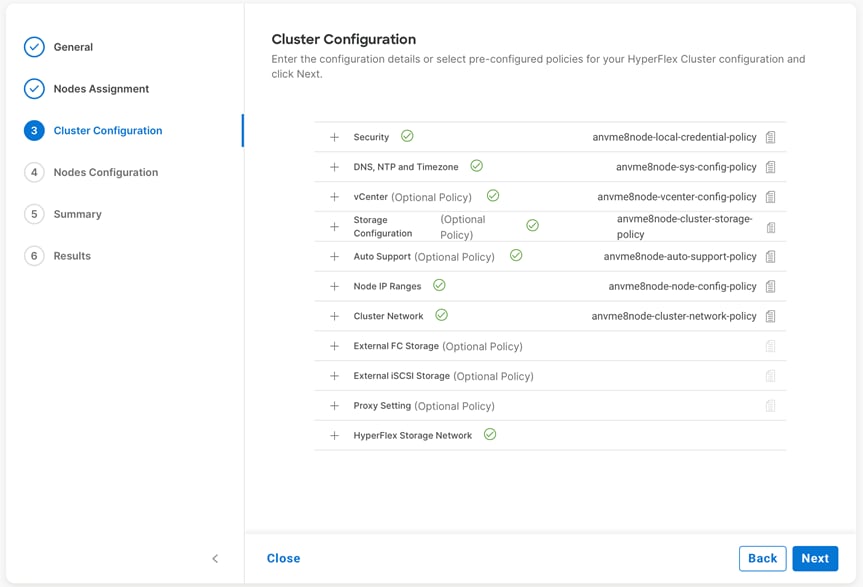
Step 25. Enter the desired HyperFlex cluster management IP address, which will be used for the HyperFlex Connect management webpage.
Step 26. Enter a value for the fourth byte of the MAC address pool which will be used to assign MAC addresses to the UCS vNICs, for example 00:25:B5:25. In most cases it is sufficient to enter the same value in the starting and ending field, and all generated MAC addresses will have the same first 4 byte values. It is important to note as detailed earlier that the Hyperflex storage network IP addresses will be derived in part from the MAC address pool prefix entered here. In order to prevent any IP address overlaps, it is important to use a unique MAC address pool prefix for each HyperFlex cluster.
Step 27. Select the desired Replication Factor.
Step 28. Click Expand All to view the node configuration for all of the HyperFlex cluster nodes. The hostnames will be automatically set, and IP address assignments will be drawn from the pool defined in the previous step which should match the ordering of the servers. The hostnames and IP addresses can be modified, if necessary. For example, if the automatic naming prefix does not result in the desired naming convention, to match the server numbering in UCS Manager or to match their physical cabling order. Modify the names and IP addresses as necessary, then click Next.
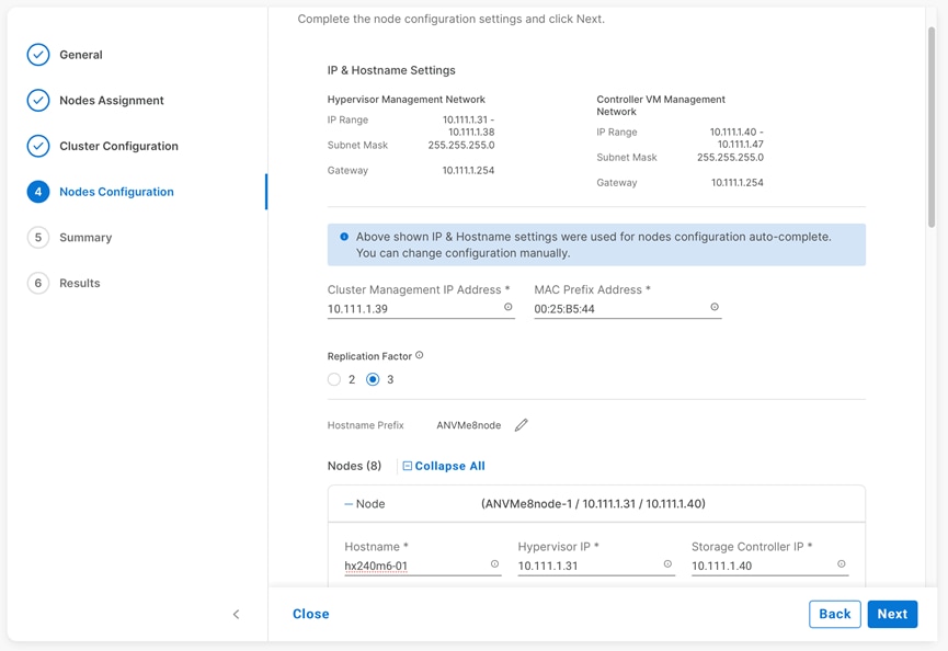
Step 29. On the Summary page, review the configuration and policies to check if there are any warnings or errors. Click Validate to validate the HyperFlex cluster configuration only without starting the deployment. This will start a series of hardware, software, and environmental checks that will take a few minutes to complete. Alternatively, click Validate & Deploy to complete validation and deployment together.
Note: This document follows the path of performing Validate & Deploy in a single step.
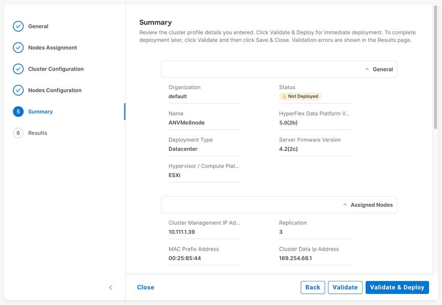
Step 30. (Optional) you can click Close to complete deployment later. Installation time will vary based on network bandwidth, but typically takes about 1-2 hours. You can remain on the results page to watch cluster deployment progress in real time. Alternatively, you may click Close to send the task into the background and navigate elsewhere within Intersight. To return to this results view, navigate back to the CONFIGURE > Policies > HyperFlex Cluster Profile list view and select the cluster name.
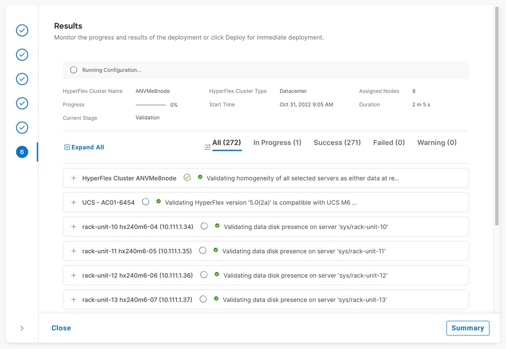
Step 31. If any validation warnings appear, review the alerts to determine if any changes need to be made to the cluster configuration or if any prerequisites have been missed. Some warnings are informational and can be ignored. If the warnings are not critical or important to your deployment, then click Continue.
Step 32. When deployment has completed successfully, click OK.
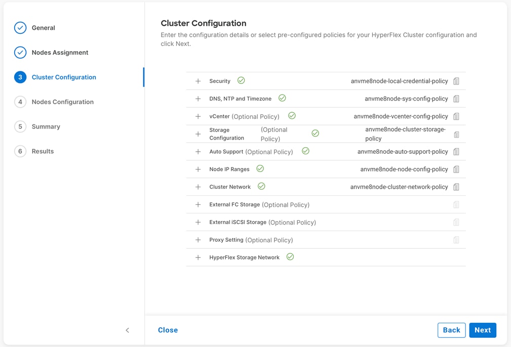
Step 33. Once back on the CONFIGURE > Profiles > HyperFlex Cluster Profile page, find the newly deployed HX cluster profile with a status of OK.
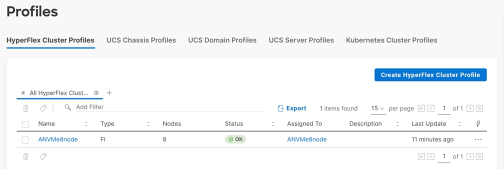
Post-install Script
Prior to putting a new HyperFlex cluster into production, a few post-install tasks must be completed. To automate the post installation procedures and verify the HyperFlex cluster configuration, a post_install script has been provided on the HyperFlex Controller VMs.
Procedure 1. Run the post installation script
Step 1. SSH to the cluster management IP address and login using “admin” as the username and the controller VM password provided during installation. Verify the cluster is online and healthy using “hxcli cluster info.”
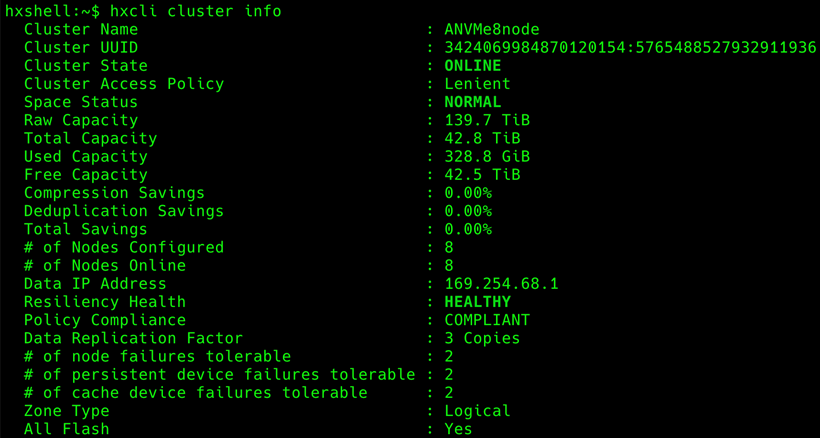
Step 2. Run the following command in the shell, and press enter:
hx_post_install
Step 3. Select the first post_install workflow type – New/Existing Cluster.
Step 4. Enter the HX Storage Controller VM root password for the HX cluster (use the one entered during the HX Cluster installation).
Step 5. Enter the vCenter server username and password.
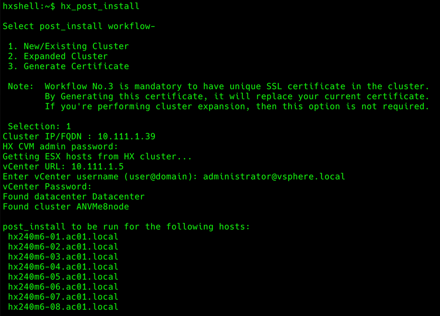
Step 6. Enter ESXi host root password (use the one entered during the HX Cluster installation).
Step 7. You must license the vSphere hosts through the script or complete this task in vCenter before continuing. Failure to apply a license will result in an error when enabling HA or DRS in subsequent steps. Enter “n” if you have already registered the license information in vCenter.
Step 8. Enter “y” to enable HA/DRS if you have the appropriate licensing to enable these features.
Step 9. Enter “y” to disable the ESXi hosts’ SSH warning.
Step 10. Add the vMotion VMkernel interfaces to each node by entering “y.” Input the netmask, the vMotion VLAN ID, plus a starting and ending vMotion IP address range to be used by the hosts. The script will assign the addresses in sequential order.
Step 11. You may add more VM network portgroups for guest VM traffic via the script. Enter “n” to skip this step. If desired, enter “y” and enter the information for the additional port groups and VLAN IDs. The VM network portgroups will be created and added to the vm-network vSwitch. This step will add identical network configuration to all nodes in the cluster.
Step 12. A health check will be run, and a summary of the cluster will be displayed upon completion of the script. Make sure the cluster is healthy.
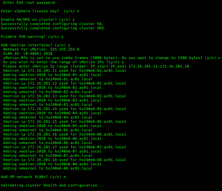
Cisco HyperFlex 2.5 and later utilizes Cisco Smart Licensing, which communicates with a Cisco Smart Account to validate and check out HyperFlex licenses to the nodes, from the pool of available licenses in the account. At the beginning, Smart Licensing is enabled but the HX storage cluster is unregistered and in a 90-day evaluation period or EVAL MODE. For the HX storage cluster to start reporting license consumption, it must be registered with the Cisco Smart Software Manager (SSM) through a valid Cisco Smart Account. Before beginning, verify that you have a Cisco Smart account, and valid Cisco HyperFlex licenses are available to be checked out by your HX cluster.
To create a Smart Account, go to Cisco Software Central > Request a Smart Account: https://webapps.cisco.com/software/company/smartaccounts/home?route=module/accountcreation .
Procedure 1. Activate and configure smart licensing
Step 1. Navigate to Cisco Software Central (https://software.cisco.com) and log in to your Smart Account.
Step 2. Click the Manage Licenses link to enter Cisco Smart Software Manager.
Step 3. Click Inventory, click General, and then click New Token.
Step 4. In the Create Registration Token dialog box, add a short Description for the token, enter the number of days you want the token to be active and available to use on other products, and check Allow export-controlled functionality on the products registered with this token.
Step 5. Click Create Token.
Step 6. From the New ID Token row, click the Actions drop-down list, and click Copy.
Step 7. From the HyperFlex Connect webpage, on the main Dashboard page, click the link at the top for “Cluster License not registered.”
Step 8. Enter or paste the Registration Token copied from Cisco Smart Software Manager, then click Register.
Step 9. Click System Information, at view the information at the top of the screen to confirm that your HX storage cluster is registered.
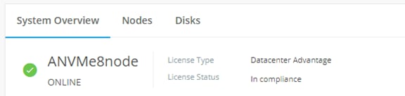
This chapter contains the following:
● Replication and Disaster Recovery
After the installation and basic configuration of the Cisco HyperFlex cluster, there are several additional features and capabilities which can be enabled and utilized. The following sections will guide you through the enablement of these features, along with any prerequisites and manual steps needed prior to using them.
Create a datastore for storing the virtual machines. This task can be completed via Cisco Intersight, or alternatively by using the HyperFlex Connect HTML management webpage.
Procedure 1. Configure a new datastore
Step 1. Log in to Cisco Intersight. From the services menu at the top of the screen, select Infrastructure Service, then from the navigation menu on the left, underneath Operate, select HyperFlex Clusters. Click on the cluster to be configured, then click on the Operate tab. Click on Datastores, then click Create Datastore.
Step 2. In the popup, enter the Datastore Name and size. For most applications, leave the Block Size at the default of 8K. Only dedicated Virtual Desktop Infrastructure (VDI) environments should choose the 4K Block Size option.
Step 3. Click Save.
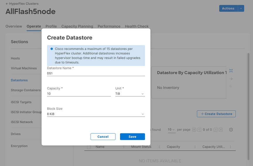
The newly created datastore will be visible as a storage location for virtual machines in the managing vCenter system. In order to perform initial testing and learn about the features in the HyperFlex cluster, create one or more test virtual machines stored on your new HX datastore to use to take snapshots, enable replication, and perform cloning operations.
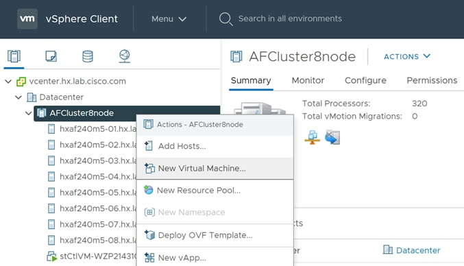
Cisco HyperFlex offers a plugin for VMware vCenter to extend the capabilities of the HTML based vSphere Client management portal with Cisco HyperFlex specific menus and tasks. The vCenter plugin allows administrators to see many of the details of the Cisco HyperFlex clusters managed by the vCenter server, as you would from either Cisco Intersight or HX Connect. In addition, contextual menus are added to the HTML UI to allow HyperFlex native instant snapshots, scheduled snapshots, and cloning of VMs directly from the vSphere Client webpage. This method may be preferred by many administrators, however the ability to perform these tasks also exists within HX Connect.
Procedure 1. Install the vCenter HTML plugin
Step 1. Download the vCenter HTML plugin zip file from the cisco.com software downloads site.
Step 2. Upload the zip file via SCP or SFTP to one of the storage controller VMs of a cluster managed by the vCenter server which requires the plugin. For example, upload the file HyperFlex-VC-HTML-Plugin-2.2.0.zip to an SCVM in the directory /home/admin.
Step 3. Log in as admin via SSH to the SCVM where the zip file was uploaded.
Step 4. Unzip the file using the command: unzip HyperFlex-VC-HTML-Plugin-2.2.0.zip
Step 5. Execute the install_vc_plugin command. Note: this is an embedded command in the HX admin console, do not attempt to execute the ./install_vc_plugin.py script that is included in the zip file.
Step 6. Enter the storage controller VM admin password, the vCenter account name and vCenter password when prompted.
Step 7. Log in to the vSphere Client and observe that Cisco HyperFlex is available in the navigation menu. In most cases, the first login will not populate the plugin with data.
Step 8. Log out of the vSphere Client, then log in again. Open the Cisco HyperFlex plugin menu and confirm that the Cisco HyperFlex clusters are listed, and the data is populated.
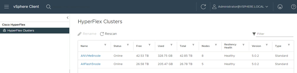
Cisco HyperFlex offers the ability to take native snapshots of virtual machines using the HXDP filesystem. These native snapshots are space efficient, have very low VM stun times, and offer high performance over long periods of use. Snapshots can be taken manually or set to a schedule and can also be used to make clones of existing virtual machines. Previous versions of the HXDP filesystem required the creation of a base or “SENTINEL” snapshot for each VM, which was a non-native snapshot created before all subsequent snapshots which would be HXDP native. Cisco HyperFlex 5.0 offloads snapshot creation to a new VAAI provider which no longer requires the creation of a base or “SENTINEL” snapshot.
Cisco strongly recommends utilizing the HyperFlex Connect UI, the HyperFlex REST API, the vSphere HyperFlex HTML client plugin, or stcli commands to create snapshots and schedules. Using the native vCenter Snapshot Manager bypasses several internal HXDP operations which would require the user to perform manual workarounds.
Procedure 1. Take an instant Cisco HyperFlex native snapshot of one or more VMs
Step 1. In the HyperFlex Connect webpage, click the Virtual Machines menu, click to check the box next to the name(s) of the VM(s) to snapshot, then click Snapshot Now.
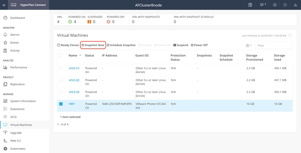
Step 2. Input the snapshot name, a description if desired, and choose whether to quiesce the VM, then click Snapshot Now.
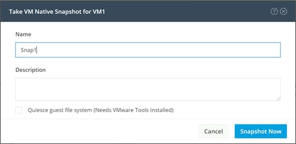
HyperFlex connect allows for the creation of scheduled snapshots of VMs at hourly, daily and/or weekly intervals. Scheduled snapshots also have a defined retention period so that older snaps will be automatically aged out of the system. In this way, scheduled snapshots can provide another layer of protection of your VMs by keeping a rolling number of hourly, daily, and weekly snapshots to revert back to in case of any data, application, or OS level problems.
Procedure 1. Schedule Cisco HyperFlex native snapshots of one or more VMs
Step 1. In the HyperFlex Connect webpage, click the Virtual Machines menu, click to check the box next to the name(s) of the VM(s) to snapshot, then click Schedule Snapshot.
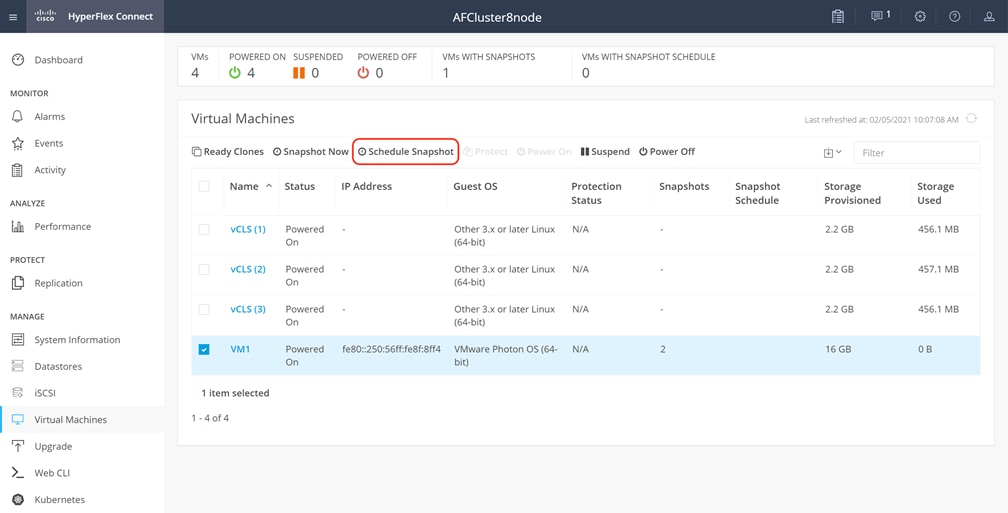
Step 2. Select the options desired for the snapshot schedule. Snapshots can be selected to occur automatically once per hour, once per day, and/or once per week. Select the times for the snapshots, the days of the week for them to be taken, along with the number of snapshots to retain. For example, this configuration would be useful for a high importance or business critical VM, because it is configured with hourly snapshots for 12 hours per day, plus daily snapshots retained for a week, then weekly snapshots retained for 4 weeks.
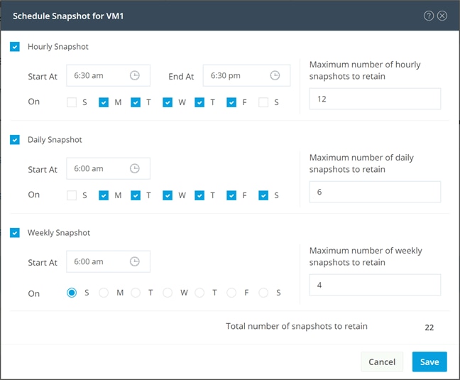
Cisco HyperFlex can create nearly instant clones of existing VMs directly via the HXDP filesystem. In the next test you will create a few clones of the test virtual machine.
Procedure 1. Create the Ready Clones
Step 1. In the Cisco HyperFlex Connect webpage, click the Virtual Machines menu, click the checkbox to select the VM to clone, then click Ready Clones.
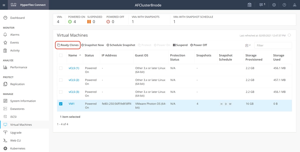
Step 2. Input the Number of clones to create, a customization specification if needed, a resource pool if needed, and a naming prefix, then click Clone to start the operation. The clones will be created in seconds.
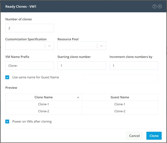
Replication and Disaster Recovery
Cisco HyperFlex native replication offers the ability to replicate virtual machines from one cluster to another for backup and disaster recovery protection. Virtual machines are replicated at designated intervals using Cisco HyperFlex native snapshots to copy the changes to the VMs over time, to a specific datastore in a paired cluster. Replication data is transferred via a dedicated virtual switch which is created by default during the installation, but not used until the replication networking configuration is set. The replication network must be unique and have its own VLAN ID assigned, bandwidth limitations can be set so as not to overwhelm the physical links with backup traffic, and a unique maximum transmission unit (MTU) can be set if needed. Cisco HyperFlex 5.0(2b) and later offers the ability to pair multiple source clusters to a single target for an N:1 backup arrangement, versus only allowing 1:1 pairing relationships. This allows a single larger centralized cluster with higher storage capacity to receive replication backups from multiple source clusters. Additionally, replicated VMs can now be restored to any location, not just their original cluster or the backup target, and VMs can be restored to a specific timed snapshot versus only the latest snapshot taken.
Replication Network Configuration
The replication network configuration for the source and target clusters must be completed using Cisco UCS Manager. This step adds the designated VLAN to be used for replication to the configuration of the management vNICs.
Procedure 1. Configure the replication network
Step 1. Using a supported web browser, log in to Cisco UCS Manager for the domain that manages the FI-based target HyperFlex cluster.
Step 2. Click LAN from the navigation menu.
Step 3. Under LAN Cloud, click VLANs.
Step 4. Click Add, enter the VLAN name and VLAN ID for the replication VLAN.
Step 5. Click OK.
Step 6. In the navigation tree, click Policies > root > Sub-Organization > YOUR ORG NAME > vNIC Template > hx- mgmt-a.
Step 7. Click Modify VLANs, click to check the replication VLAN which was just created, then click OK.
Step 8. Repeat steps 1-7 in Cisco UCS Manager for the source HyperFlex cluster(s).
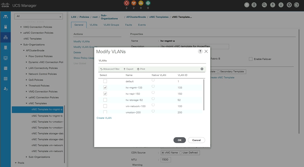
Target Cluster Configuration
After the replication VLAN is configured in Cisco UCS Manager, the target cluster can be configured. The N:1 target cluster must be previously installed, either using Cisco Intersight, or using the on-premises installer and subsequently imported into Cisco Intersight.
Procedure 1. Configure the target cluster
Step 1. Log in to Cisco Intersight. From the services menu at the top of the screen, select Infrastructure Service, then from the navigation menu on the left, underneath Operate, select HyperFlex Clusters.
Step 2. From the list of clusters, click the ellipsis (...) at the end of the row for the target cluster, then click Configure Backup.
Step 3. Expand the Replication Network Configuration section. Enter the replication VLAN ID, a bandwidth limit in Mbps, the replication network MTU, plus the starting and ending IP addresses for the replication network, the subnet mask, and the replication network gateway.
Step 4. Click Next.
Step 5. Click Validate & Deploy to begin the replication network configuration job. A list of configuration jobs will be shown with the newly submitted job at the top. Observe the status of the job, or alternatively click the job to view the details as it executes. Detailed information about the job status can also be seen in the HyperFlex Connect Activity screen.
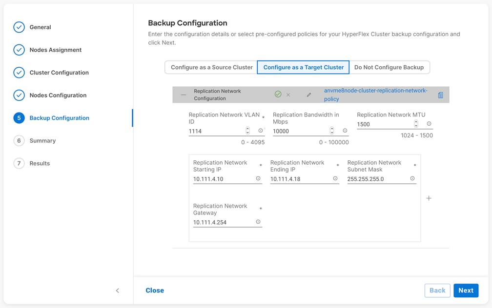
Source Cluster Configuration
Once a target cluster is configured, the source cluster(s) can be configured with their replication network settings and backup policies.
Procedure 1. Configure the source cluster(s)
Step 1. Log in to Cisco Intersight. From the services menu at the top of the screen, select Infrastructure Service, then from the navigation menu on the left, underneath Operate, select HyperFlex Clusters.
Step 2. From the list of clusters, click the ellipsis (...) at the end of the row for the source cluster, then click Configure Backup.
Step 3. Expand the Replication Network Configuration section. Enter the replication VLAN ID, a bandwidth limit in Mbps, the replication network MTU, plus the starting and ending IP addresses for the replication network, the subnet mask, and the replication network gateway.
Step 4. Expand the Virtual Machine Backup Configuration section. Check the Enabled box, then enter the replication time in minutes, and the number of local and remote snapshots to retain for the VMs.
Step 5. Select the target cluster to replicate the snapshots to and select if encryption is enabled for the target cluster, then click Next.
Step 6. Click Validate & Deploy to begin the replication network configuration job. A list of configuration jobs will be shown with the newly submitted job at the top. Observe the status of the job, or alternatively click the job to view the details as it runs. Detailed information about the job status can also be seen in the HyperFlex Connect Activity screen.
Step 7. Repeat steps 3-7 for each additional source cluster which requires protection and replication of the VMs.
Protect VMs
VMs will be automatically protected if they reside in the newly created datastore in the source cluster(s). The protected datastores have a prefix of "backup-source-ds_" followed by the last 8 digits of the cluster UUID. Creating or moving a VM in this datastore will enable automatic protection according to the policy settings set when replication was enabled. VMs that are moved out of the protected datastores will lose protection. If a VM resides in multiple datastores then they will not be protected. A similar datastore is created on the target cluster which is automatically managed and requires no end-user interaction.
Restore VMs
Protected VMs can be restored via Cisco Intersight, either in the original cluster or in a different cluster. When restoring to the original cluster, the restored VM can use the original name, or it can be restored with a new name. If the original VM still exists, it will be powered off and rolled back to the specified snapshot, then powered back on. If the original VM has been deleted, then it will be recreated. Restorations to a different cluster must use a new specified name. Recovered VMs in the original cluster will be placed into the protected datastore, so the restored VM will be automatically protected just as the original VM was.
Procedure 2. Restore a VM
Step 1. Using a supported web browser, log in to Cisco Intersight: https://www.intersight.com.
Step 2. On the left-hand side menu, click OPERATE > HyperFlex Clusters, then click the Backups tab at the top.
Step 3. Click Protected VMs, then from the list of protected VMs, click the ellipsis (...) at the end of the row for the VM to restore, and click Restore from Backup.
Step 4. Select the snapshot to restore, then click Next.
Step 5. Select the cluster to restore the VM to, then click Next.
Step 6. Enter the desired name of the restored VM and the desired power state, then click Next.
Step 7. Review the choices in the Summary screen, then click Restore.
Step 8. Observe the status of the restore job on the Restore Activity screen until the job is completed.
Remove Protected VMs
Moving a VM from a protected datastore or deleting a VM can leave behind the snapshot data in the source and target clusters, plus information retained in Cisco Intersight. To remove the snapshot data from the source and target clusters, and from Cisco Intersight after a protected VM has been moved or deleted, a CLI command must be run.
Procedure 1. Remove the snapshot data
Step 1. Log in via SSH to the management IP address of the source HyperFlex Edge cluster, as user "admin" with the appropriate password.
Step 2. From the command line, enter the command: stcli dp vm list --brief
admin:~$ stcli dp vm list --brief
vmInfo:
----------------------------------------
uuid: 420f940b-66b5-70bc-a02d-0fc9ca3b8429
name: Replica1
----------------------------------------
uuid: 420f1a91-6b8c-f316-5f4a-c2b5ec520f7f
name: Replica2
----------------------------------------
Step 3. Identify the VM which no longer requires snapshot data to be preserved, then enter the command: stcli dp vm delete --vmid <VM UUID>
admin:~$ stcli dp vm delete --vmid 420f1a91-6b8c-f316-5f4a-c2b5ec520f7f
Cisco HyperFlex offers several features to enhance the overall security of the system and the data stored in the HXDP filesystem. Data-at-rest encryption secures the data stored on the system from unauthorized removal or theft by encrypting all incoming data before it is written to any disk, both in cache and long-term storage. Secure boot ensures that malicious code is not injected or executed on the system, which could possibly compromise data integrity or unauthorized access by attackers. A key component of any secure system is logging of events and access; therefore Cisco HyperFlex offers audit logging to allow for event and security log storage outside of the system for later review and analysis if needed.
Data-at-rest Software Encryption
Cisco HyperFlex has offered the ability to encrypt the data stored in the filesystem via the use of self-encrypting drives (SEDs). While effective, this method requires the system to be purchased with SEDs, which precludes the ability to encrypt the data at a later time if the system was initially purchased with standard disks. A new feature in Cisco HyperFlex enables pure software-based data encryption of all data in the filesystem without the requirement to purchase SEDs. The data encryption method is high performance, with minimal impact to storage bandwidth or latency, offering enhanced data security with no downside. Cisco Intersight manages the keys natively with Intersight Key Manager, which simplifies deployment by eliminating the overhead of key management. HyperFlex Software Encryption is FIPS 140-2 compliant and supports 256-bit AES-GCM inline encryption. HyperFlex Software Encryption has the following requirements and guidelines:
● HyperFlex Software Encryption requires HXDP Release 5.0(1b) and later. HyperFlex stretched clusters can be enabled for Software Encryption when running Release 5.0(2a) and later.
● Cisco HyperFlex Data Platform Datacenter Premier licenses are required.
● Each converged node in the HyperFlex cluster must be claimed in Cisco Intersight and configured with Intersight Essentials or above licenses.
● An encryption passphrase must be supplied. This passphrase must be stored securely and cannot be recovered if lost or forgotten.
● SED HyperFlex configurations are not supported with HyperFlex Software Encryption.
● HyperFlex Software Encryption is supported only with VMware ESXi hypervisors.
● HyperFlex Software Encryption cannot be enabled on existing Datastores, it can only be enabled for a new encrypted Datastore.
● Once HyperFlex Software Encryption is enabled for a cluster/datastore, it cannot be disabled for the cluster or datastore.
● Once HyperFlex Software Encryption is enabled for a cluster, administrators can create either encrypted or non-encrypted datastores.
Configuration of Cisco HyperFlex Software Encryption requires the purchase of a specific software PID (HXDP-SW-PKG-SE-K9=) in addition to the standard Cisco HyperFlex HXDP software. This zero-cost license entitles you to download a software encryption package which must be installed on the cluster before encryption is enables via Cisco Intersight. The encryption software package is available for download from the My Cisco Entitlements (MCE) located within Cisco Software Central here: https://software.cisco.com/software/csws/ws/platform/home?locale=en_US&locale=en_US#
For ordering information, view the Cisco HyperFlex Ordering and Licensing guide located here: https://www.cisco.com/c/en/us/support/hyperconverged-systems/hyperflex-hx-data-platform-software/products-release-notes-list.html
Procedure 1. Enable Software Encryption
Step 1. Download the Cisco HyperFlex Software Encryption package from the My Cisco Entitlements (MCE) website.
Step 2. For clusters of 3-12 nodes, upload the encryption package using SFTP or SCP to the cluster management IP address using the admin account. The package should be located in the /home/admin directory.
Step 3. For clusters of 13 nodes or more, upload the encryption package using SFTP or SCP to each node using the admin account. The package should be located in the /home/admin directory on all of the nodes.
Step 4. For clusters of 3-12 nodes, log in to the cluster management IP address using the admin account and install the software package using the command below:
priv install-package --cluster --path /home/admin/storfs-se-core_<version>_x86_64.deb
Step 5. For clusters of 13 nodes or more, log in to each node using the admin account and install the software package using the command below:
priv install-package --local --path /home/admin/storfs-se-core_<version>_x86_64.deb
Step 6. Log in to Cisco Intersight. From the services menu at the top of the screen, select Infrastructure Service, then from the navigation menu on the left, underneath Operate, select HyperFlex Clusters. Note that the column named Software Encryption for the cluster now shows a status of “Not Configured” instead of “Not Capable.”
Step 7. Click the ellipses (…) to the right of the cluster and select Configure Encryption.
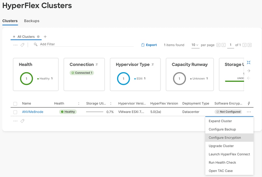
Step 8. Select to either supply your own passphrase or use an auto generated passphrase. Ensure that you have stored a copy of the passphrase on your own, or copied the auto generated passphrase by clicking the Copy Passphrase button. Check the box for “I have stored the passphrase for future use.,” then click Configure.
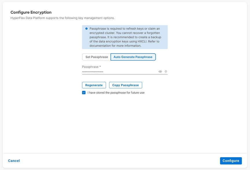
Step 9. Observe the status of the job which enables Software Encryption on the cluster until it completes.
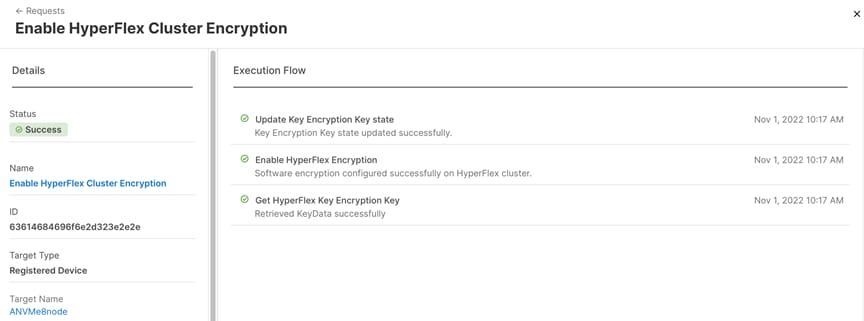
Step 10. Note that the column named Software Encryption for the cluster now shows a status of “Enabled.”
Step 11. Create a new Datastore, noting that the checkbox for “Encrypt Datastore” now exists.
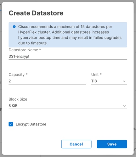
Key Backup
The data encryption key (DEK) is stored in multiple locations throughout the cluster to prevent data loss. However, to safeguard against a catastrophic failure, it is highly recommended to make a manual backup of the DEK after encryption is enabled, or any time a rekey operation is performed.
Procedure 1. Manually backup the DEK
Step 1. Log in to the Cisco HyperFlex cluster management IP address via SSH, using the admin account.
Step 2. Enter the following command to create a key backup file:
hxcli encryption backup-keys -f /home/admin/<filename>
Step 3. Enter a password to secure the DEK backup file.
Step 4. Copy the key backup file to a secure location outside of the cluster using SFTP or SCP.
Secure Erase
If a predictive failure of a drive were to occur, data security or compliance requirements may mandate that drives be securely wiped or erased before their removal. Drives can be manually erased in Cisco HyperFlex via the command line. Any drive which is erased cannot be reintroduced to the same cluster again.
Procedure 1. Securely erase a drive
Step 1. Log in to the Cisco HyperFlex cluster management IP address via SSH, using the admin account.
Step 2. Enter the following command to securely erase a disk, choosing mode 0 for a basic erase, or mode 1 or 2 for a more thorough overwrite:
secure_disk_erase -d <disk> -m <mode>
For example: secure_disk_erase -d /dev/sdh -m 1
Step 3. Observe the status of the drive erasure with the following command:
secure_disk_erase -d /dev/sdh --progress
Step 4. When the drive erasure is completed, remove the drive from the system.
Encryption Re-key
Clusters with encryption enabled can have their keys replaced with new ones at any time, either in response to a suspected attack or intrusion, as part of a scheduled security sweep, or by company policy. Performing a Rekey operation is non-intrusive and requires that the existing encryption passphrase is known.
Procedure 1. Perform a Re-key operation
Step 1. Log in to Cisco Intersight. From the services menu at the top of the screen, select Infrastructure Service, then from the navigation menu on the left, underneath Operate, select HyperFlex Clusters. Click on the cluster to be re-keyed, then click on the Operate tab. Click on Encryption, then click the Re-key button.
Step 2. Select either the manual or automatic passphrase button, then enter the existing encryption passphrase for the cluster. Click the button to copy the auto generated passphrase if necessary and check the box for “I have stored the passphrase for future use.”
Step 3. Click Re-key.
Step 4. Monitor the status of the job until it has completed successfully.
Secure Boot
Cisco HyperFlex version 5.0(2a) and later clusters are enabled for Secure Boot Mode during the initial installation. This configuration requires that all drivers and modules loaded by the node during boot are digitally signed and marked as safe, preventing malicious code execution from happening during the system startup process. For clusters that have been upgraded from an earlier version, Secure Boot Mode must be manually enabled. All nodes in a cluster must be configured to use Secure Boot Mode together, and the setting must be enabled using the HyperFlex Connect management page as an upgrade task. Attempting to manually configure secure boot via Cisco UCS Manager can cause unexpected behavior and failures. The upgrade job will enable Secure Boot Mode on each server one-by-one and reboot them each in turn. Because of this behavior, the vCenter cluster must have DRS and vMotion enabled to automatically evacuate the VMs from each host as they are rebooted. Each node takes roughly 15 minutes to evacuate, reboot and for the cluster to return to a healthy state before the next reboot will proceed.
Procedure 1. Enable Secure Boot
Step 1. From the HyperFlex Connect webpage, click Upgrade.
Step 2. Click Check Upgrade Eligibility.
Step 3. Click the option for Secure Boot Mode, then enter the UCS Manager IP address, username, and password, plus the vCenter username and password, then click Validate.
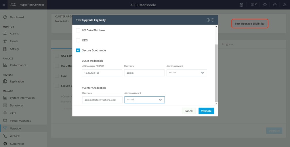
Step 4. The test will take a few minutes to finish. After it is complete, view the results of the eligibility test at the top of the page.

Step 5. If the test successfully confirms the eligibility of the cluster to use Secure Boot Mode, then continue by checking the box for Secure Boot Mode, then enter the UCS Manager IP address, username, and password, plus the vCenter username and password, then click Upgrade.
Step 6. Observe the status of the upgrade job as the nodes are reconfigured and rebooted.
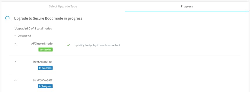
Step 7. After the upgrade job completes, the Secure Boot Mode status can be confirmed in the System Information page. Click on System Information, then from the Actions menu click Check Secure Boot Status.
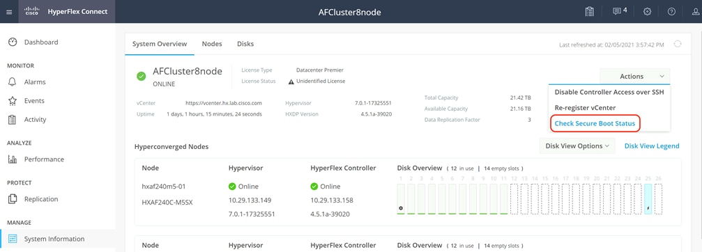
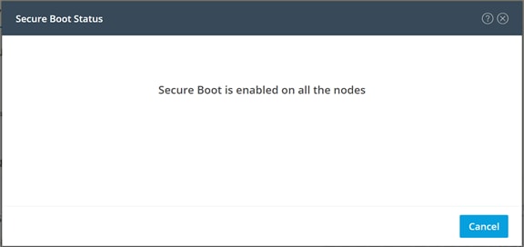
Audit Logging
By default, the HyperFlex controller VMs store logs locally for many functions, including the filesystem logs, security auditing, CLI commands and shell access, single sign-on logs, and more. These logs are rotated periodically and could be lost if there were a total failure of a controller VM. In order to store these logs externally from the HyperFlex cluster, audit logging can be enabled in HX Connect to send copies of these logs to an external syslog server. From this external location, logs can be monitored, generate alerts, and stored long term. HX Connect will not monitor the available disk space on the syslog destination, nor will it generate an alarm if the destination server is full.
Procedure 1. Enable audit logging
Step 1. Use a web browser to open the HX cluster IP management URL.
Step 2. From the HyperFlex Connect webpage, click the gear shaped icon in the upper right-hand corner, and click Audit Log Export Settings.
Step 3. Click to check the box to Enable audit log export to an external syslog server.
Step 4. Enter the syslog server IP address and TCP port.
Step 5. Choose TCP or TLS as the connection type. If using TLS, client certificate and private key pair files must be provided. Alternatively, a self-signed certificate can be used. Click browse to select the appropriate files.
Step 6. Click OK.
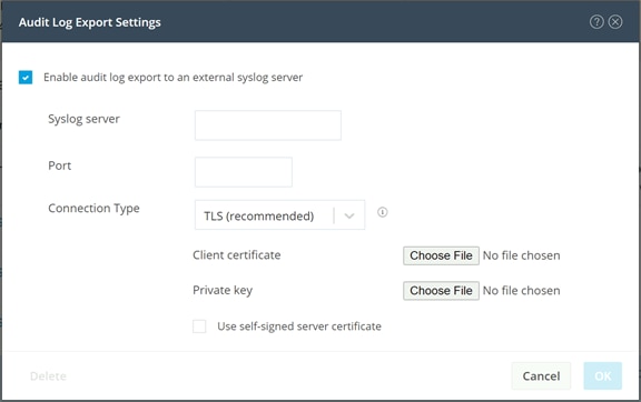
Note: Audit log exports can be temporarily disabled or completely deleted at a later time from the same location.
To store ESXi diagnostic logs in a central location if they are needed to help diagnose a host failure, it is recommended to enable a syslog destination for permanent storage of the ESXi host logs for all Cisco HyperFlex hosts. It is possible to use the vCenter server as the log destination in this case, or another syslog receiver of your choice. Syslog settings can be changed via the vSphere HTML5 client webpage by editing the advanced system setting named “Syslog.global.LogHost”. Alternatively, a faster method can be done via the CLI of the individual ESXi hosts as shown below.
Procedure 2. Configure syslog for ESXi
Step 1. Log on to the ESXi host via SSH as the root user.
Step 2. Enter the following commands, replacing the IP address in the first command with the IP address of the vCenter server that will receive the syslog logs:
[root@hx220-01:~] esxcli system syslog config set --loghost='udp://10.29.133.120'
[root@hx220-01:~] esxcli system syslog reload
[root@hx220-01:~] esxcli network firewall ruleset set -r syslog -e true
[root@hx220-01:~] esxcli network firewall refresh
Step 3. Repeat for each ESXi host.
Cisco HyperFlex offers the ability to present internal storage capacity from the Hyperflex distributed filesystem to external servers or VMs via the Internet Small Computer Systems Interface (iSCSI) protocol. Presenting storage via iSCSI differs from the standard storage presentation in HyperFlex, in that HXDP normally stores virtual disk files for VMs on its internal distributed NFS-based filesystem, whereas iSCSI presents raw block-based storage devices to external clients via an IP network. These external clients can be configured with hardware or software-based iSCSI initiators, each with a unique iSCSI Qualified Name (IQN). The external clients communicate with the HyperFlex cluster via their initiators over an IP network to mount the presented storage devices, which appear to the clients as a standard raw block-based disk. In truth, the mounted storage devices are virtualized, drawn from the overall HXDP filesystem via software and the data is distributed across the entire HyperFlex cluster. The external clients can truly be external servers or VMs running in other systems but could also be VMs running within the Cisco HyperFlex cluster itself. Common uses for iSCSI mounted storage include database systems, email systems and other clustered solutions, which commonly need simultaneous shared access to raw disk devices for shared data, logs, or quorum devices. Additionally, iSCSI storage can be used when external clients simply need additional storage space but adding more physical storage to the systems themselves is not practical or possible. The iSCSI storage feature is also utilized for Kubernetes persistent volumes via our Cisco HyperFlex CSI plugin, which is documented in other Cisco Validated Design papers.
From the Hyperflex Connect management webpage, the HyperFlex cluster can be configured with additional IP addresses within a dedicated VLAN for connectivity; one for the cluster and one more for each of the individual nodes. These addresses become the endpoints for connections from the external clients to send iSCSI based I/O traffic from their iSCSI initiators. Within HyperFlex, iSCSI Targets are created, and within each target one or more Logical Unit Numbers (LUNs) are created, essentially a numbered device which appear to the external clients as raw block storage devices. To control access to the LUNs, Initiator Groups are created which list the unique IQNs of one or more client initiators which need to access a LUN. Initiator Groups and Targets are then linked to each other, acting as a form of security masking to define which initiators can access the presented LUNs. In addition, authentication using Challenge-Handshake Authentication Protocol (CHAP) can be configured to require password-based authentication to the devices. Lastly, iSCSI LUNs can have snapshots taken via the Cisco HyperFlex API, and can be cloned within the HyperFlex system as a crash-consistent copy, or an application consistent clone can be created for clients running Microsoft Windows Server which are also running the HX Windows Agent for VSS.
Figure 25 details the logical design for iSCSI storage presentation from a Cisco HyperFlex cluster.
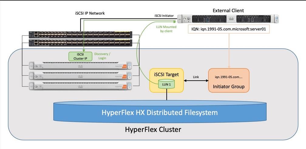
Connectivity to iSCSI storage is supported for Microsoft Windows Server 2016, Windows Server 2019, Ubuntu Linux 18.04 and 20.04, Oracle Linux 7, Red Hat Enterprise Linux 7, and Red Hat Enterprise Linux 8. Multipath I/O (MPIO) can be enabled in the guest OS if desired. When configuring multiple paths to the iSCSI devices, it is recommended to configure each initiator to use the HyperFlex cluster’s iSCSI clustered IP address as the target. This method will see the cluster sending a “TargetMoved” response to the initiators, redirecting them to the best node for load balancing and high availability (HA). Alternatively, each initiator can be configured with a specific node’s IP address to achieve load balancing and HA, although this configuration requires the MPIO software to properly handle link down events due to node reboots, because direct connections to the nodes do not benefit from the automatic cluster failover capability.
The first step to enable external iSCSI storage presentation is to configure the iSCSI network where the devices will be accessed. The traffic will ingress/egress via the port groups named “Storage Controller ISCSI Primary” and “Storage Controller ISCSI Secondary,” which are part of the virtual switch named “vswitch-hx-storage-data.” Although there are two port groups, only the primary port group is used at this time. A clustered IP address is set, and a pool of addresses is created to assign to the individual nodes. The pool can be made larger than the number of nodes in order to accommodate future growth. A VLAN ID is assigned to the port groups for the iSCSI traffic, and it is required to use a VLAN ID other than the one used for HyperFlex management or storage traffic. In general, a dedicated VLAN used only for iSCSI traffic is recommended. If the VLAN does not exist in the Cisco UCS configuration it will be created, and the VLAN ID will be assigned to the “storage-data” vNIC templates. These addresses and settings were previously defined in the IP Addressing section as the HyperFlex iSCSI interfaces.
Procedure 1. Configure the iSCSI networking settings
Step 1. Log in to Cisco Intersight. From the services menu at the top of the screen, select Infrastructure Service, then from the navigation menu on the left, underneath Operate, select HyperFlex Clusters. Click on the cluster to be configured, then click on the Operate tab. Click iSCSI Network, then click the link for Configure Network.
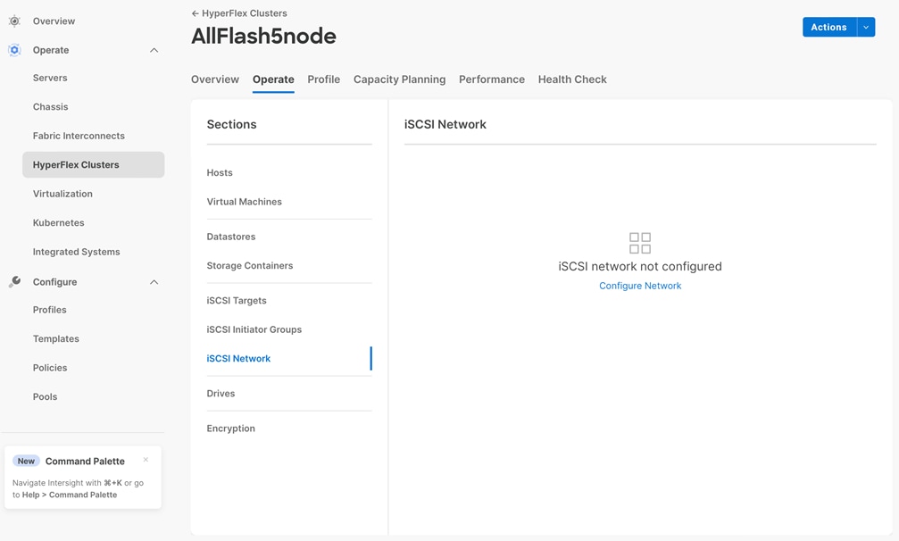
Step 2. Enter the subnet used for iSCSI traffic in CIDR notation. If the subnet is routable enter the default gateway IP address.
Step 3. Enter the starting and ending addresses for the IP address range that will be assigned to the nodes.
Step 4. Enter the iSCSI Storage IP which will be assigned to the cluster.
Step 5. If required, check the box to allow jumbo frames on the iSCSI network.
Step 6. Enter the VLAN ID for the subnet that will carry the iSCSI traffic.
Step 7. Click Configure Network.
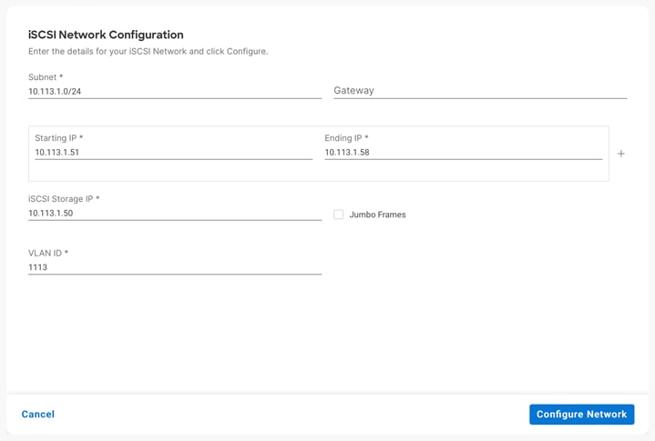
Step 8. A job will be started to configure the iSCSI networking settings. Monitor the status of the job until it completes.
Note: If initiators will be connecting from a subnet outside of the one configured for iSCSI on the HyperFlex cluster, for example if the iSCSI subnet is routable and a client connects from a different subnet, then an entry must be made into the iscsi allow list before connections will succeed. To add an entry, from the HyperFlex admin CLI, enter: hxcli iscsi allowlist add –-ips 192.168.100.10
Initiator Groups contain lists of the IQNs of the iSCSI initiators of one or more external clients. A common practice which mimics zoning in Fibre Channel storage systems, is to create a single group per unique client, and list only the initiators used by that client if there are more than one (for example, it is possible to configure unique IQNs per interface in Linux). This allows for granular additions or removals of hosts from accessing targets and LUNs one by one and simplifies diagnosis and troubleshooting. The process for finding the IQN of each client machine or initiator is unique to each operating system and is not covered in this document.
Procedure 1. Create an iSCSI Initiator Group
Step 1. Log in to Cisco Intersight. From the services menu at the top of the screen, select Infrastructure Service, then from the navigation menu on the left, underneath Operate, select HyperFlex Clusters. Click on the cluster to be configured, then click on the Operate tab. Click on iSCSI Initiator Groups, then click the button for Create iSCSI Initiator Group.
Step 2. Enter the name if the group, then enter the IQN and optionally their IP address(es).
Step 3. Add any additional IQNs as needed by clicking the + icon on the right, then click Create.
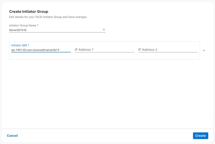
Note: Do not use the underscore character “_” in the name of Initiator Groups, iSCSI targets or LUNs. Doing so can cause discovery failures.
ISCSI Targets act as storage resource containers that are contacted by the clients and scanned during discovery. The target contains the LUNs which are created for the client(s) to access and are then linked with one or more Initiator Groups. This link acts as a form of masking, defining which initiators can communicate with which targets, and hence which LUNs can be discovered and accessed by whom. LUNs can only be created in a single target; therefore, the common best practice is to create all of the LUNs needed by one or more hosts into a single target, then link the appropriate Initiator Groups with the target. For example, two clustered database servers may need access to a data disk, a log disk, and a witness or quorum disk. Creating one target with the three LUNs, then linking the target with two Initiator Groups, one per DB host, is a common approach.
Procedure 1. Create an iSCSI Target
Step 1. Log in to Cisco Intersight. From the services menu at the top of the screen, select Infrastructure Service, then from the navigation menu on the left, underneath Operate, select HyperFlex Clusters. Click on the cluster to be configured, then click on the Operate tab. Click on iSCSI Targets, then click the Create button.
Step 2. Enter the name for the Target.
Step 3. Check the box to enable CHAP authentication if desired, then enter the username and password.
Step 4. From within the iSCSI Targets screen, a new LUN can be created if desired by clicking the radio button next to LUNs to Enable. Click the Create LUN button to enter the details of the new LUN, then click Create LUN.
Step 5. From within the iSCSI Targets screen, the target can be linked with an existing iSCSI Initiator Group if desired, by clicking the radio button next to Link Initiator Groups to Enable. Click the Link Initiator Group button, select the group to be linked from the list, then click Link.
Step 6. Click Create.
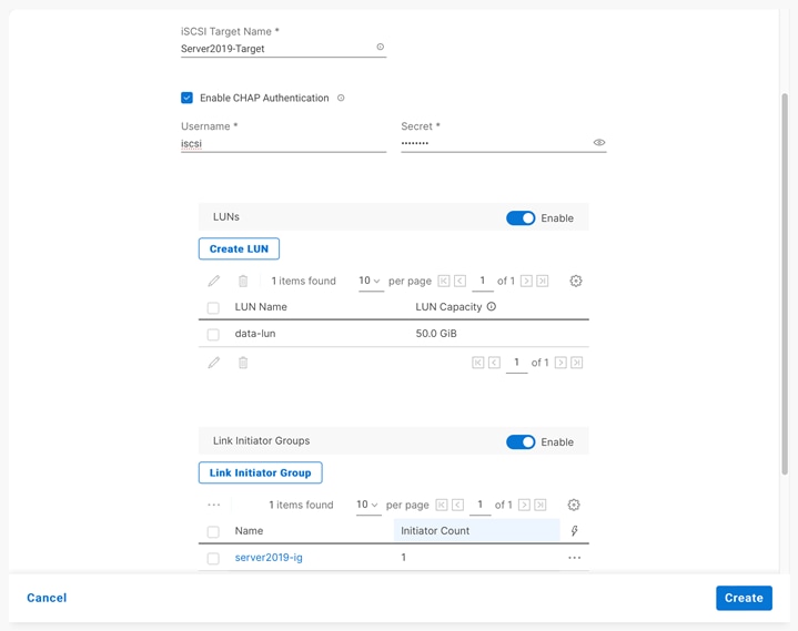
Within an iSCSI Target, the one or more LUNs needed by the iSCSI client machines can be created if not created as part of the iSCSI Target creation.
Procedure 1. Create an iSCSI LUN
Step 1. Log in to Cisco Intersight. From the services menu at the top of the screen, select Infrastructure Service, then from the navigation menu on the left, underneath Operate, select HyperFlex Clusters. Click on the cluster to be configured, then click on the Operate tab. Click on iSCSI Targets.
Step 2. Select the iSCSI target where the new LUN will be created.
Step 3. Click the tab for LUNs, then click Create.
Step 4. Enter the name for the LUN and the desired size, then click Create LUN.
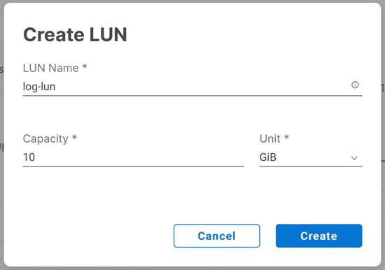
Note: Do not use the underscore character “_” in the name of Initiator Groups, iSCSI targets or LUNs. Doing so can cause discovery failures.
Link Targets and Initiator Groups
The final step to configure iSCSI storage presentation is to link the iSCSI Target with one or more Initiator Groups if not done as part of the iSCSI Target creation. All of the initiators in the linked Initiator Groups will immediately gain access to the LUNs in the Target once this step is completed.
Procedure 1. Link an iSCSI Target with an Initiator Group
Step 1. Log in to Cisco Intersight. From the services menu at the top of the screen, select Infrastructure Service, then from the navigation menu on the left, underneath Operate, select HyperFlex Clusters. Click on the cluster to be configured, then click on the Operate tab. Click on iSCSI Targets.
Step 2. Select the iSCSI target which needs to be linked to an initiator group.
Step 3. Click the tab for Linked Initiator Groups, then click Link.
Step 4. Check the box next to the group(s) that you wish to link, then click Link.
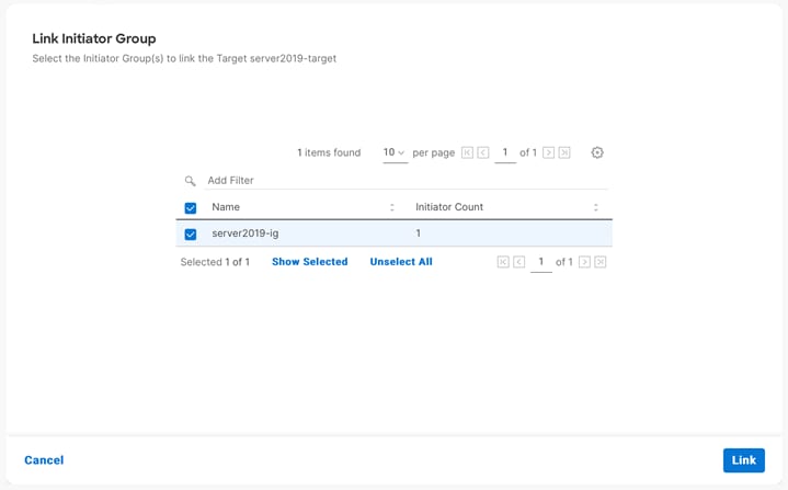
When the preceding steps are finished, the process to discover and mount the LUNs is done from the client’s operating system. The processes for different operating systems are unique to each other and are not covered as part of this document. In general, it should be sufficient to configure the client machine’s iSCSI initiator(s) to discover available storage using the HyperFlex cluster’s iSCSI clustered IP address as the target. Configure the target to use CHAP authentication if configured, and the connection should succeed, showing the LUNs available in the iSCSI Target within the HyperFlex cluster. The client can then be configured to automatically mount the LUNs for use after each reboot.
There are many circumstances where an exact duplicate of an existing LUN may need to be created. Clones of iSCSI LUNs can be made within Cisco HyperFlex, either as crash-consistent or application-consistent copies. A crash consistent clone is a copy where the operating system or application using the newly cloned LUN can safely and reliably perform a recovery against the cloned data and return to normal service. An application-consistent clone is one where such recovery steps could be time consuming, risky, or any possible data loss is deemed unacceptable. To perform an application-consistent clone operation, the OS and applications using the original LUN to be cloned must be paused and quiesced, so that no active or pending I/O is happening against the LUN. This requires an operating system or application-level agent software package to run in order to coordinate this pausing and quiescing activity with the HyperFlex cluster. An agent for Microsoft Windows Server 2016 or later is available for this purpose and must be installed prior to attempting to take an application-consistent clone of a LUN. The cloned LUN is created in its own new iSCSI Target, and after the cloning is completed, the new Target must be linked with an Initiator Group in order for a client to gain access to the newly cloned LUN.
Procedure 1. Clone an iSCSI LUN
Step 1. Log in to Cisco Intersight. From the services menu at the top of the screen, select Infrastructure Service, then from the navigation menu on the left, underneath Operate, select HyperFlex Clusters. Click on the cluster to be configured, then click on the Operate tab. Click on iSCSI Targets.
Step 2. Select the target which contains the LUN to be cloned.
Step 3. Click the tab for LUNs, then click on the ellipses (…) to the right of the LUN you wish to clone, then click Clone.
Step 4. Enter the new destination iSCSI Target name.
Step 5. Click the button for Application consistency if desired, then enter a valid username and password for the host system accessing the original LUN, which is also running the HyperFlex agent software.
Step 6. Click the button to enable CHAP authentication if desired and enter the appropriate username and password.
Step 7. Click Next
Step 8. Enter the name of the new destination LUN, then click Clone.
iSCSI Snapshots
ISCSI LUNs can have snapshots taken via the Cisco HyperFlex API. One or more LUNs can be placed into a consistency group to keep the snapshots of all the LUNs in that group taken simultaneously so they remain aligned. A use case for this alignment would be a database application which needs their data and log volumes snapshotted at the same time, so they do not have inconsistent data to be replayed. Please refer to the Cisco HyperFlex API documentation for details on how to use this feature.
Auto-Support should be enabled for all clusters during the initial HyperFlex installation. Auto-Support enables Call Home to automatically send support information to Cisco TAC, and notifications of tickets to the email address specified. If the settings need to be modified, they can be changed in the HyperFlex Connect HTML management webpage.
A list of events that will automatically open a support ticket with Cisco TAC is as follows:
● Cluster Capacity Changed
● Cluster Unhealthy
● Cluster Health Critical
● Cluster Read Only
● Cluster Shutdown
● Space Warning
● Space Alert
● Space Critical
● Disk Blacklisted
● Infrastructure Component Critical
● Storage Timeout
Procedure 1. Change Auto-Support settings
Step 1. From the HyperFlex Connect webpage, click the gear shaped icon in the upper right-hand corner, and click Auto-Support Settings.
Step 2. Enable or disable Auto-Support as needed.
Step 3. Enter the email address to receive alerts when Auto-Support events are generated.
Step 4. Enter in the information for a web proxy if needed.
Step 5. Click to accept the terms and conditions, which can be reviewed as needed.
Step 6. Click OK.
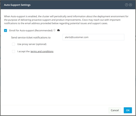
Note: Alarms generated on the HyperFlex cluster can also be configured to create emails sent directly to a desired recipient.
Procedure 2. Enable direct email notifications
Step 1. From the HyperFlex Connect webpage, click the gear shaped icon in the upper right-hand corner, and click Notifications Settings.
Step 2. Enter the DNS name or IP address of the outgoing email server or relay, the email address the notifications will come from, and the recipients.
Step 3. Click OK.
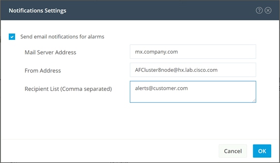
Cisco HyperFlex Expansion
Cisco HyperFlex clusters can be expanded with additional converged nodes, or by adding compute-only nodes. When the cluster needs additional storage space or higher storage performance, adding converged nodes is the appropriate path and will also provide more computing power and memory space for additional VMs. When storage space and performance is adequate, but additional processing power and memory space is needed to run more VMs, adding compute-only nodes is the appropriate solution. Additionally, because compute-only nodes do not participate in the HXDP filesystem, they do not have storage controller VMs, therefore all of the CPU and memory capacity of a compute-only node is available to the guest VMs, making compute-only nodes a good choice for VMs with very high CPU and memory requirements.
Expanding a Cisco HyperFlex cluster is done using Cisco Intersight; therefore the additional nodes must be already claimed in Intersight with no configuration applied to them. A new converged node would arrive with the factory pre-build process completed; therefore no manual steps would be required to expand an existing cluster with a newly purchased converged node. All compute-only nodes will require manual steps to install the required Cisco HyperFlex customized ESXi hypervisor to the node, either before the expansion process is begun, or as a step during the expansion process. The following technical guidelines must be followed when adding compute-only nodes to a Cisco HyperFlex cluster:
● The number of compute-only nodes cannot exceed the number of HyperFlex converged nodes within a single HyperFlex cluster unless the appropriate HyperFlex Enterprise licenses have been purchased, allowing up to a 2:1 ratio of compute-only nodes to converged nodes.
● The Cisco UCS infrastructure firmware revision, which provides the firmware for Cisco UCS Manager and the Fabric Interconnects, must be maintained at the minimum version required for the HyperFlex converged nodes, or higher, at all times.
● The version of VMware ESXi installed on the compute-only nodes must be compatible with the Cisco HyperFlex version in use, and it must match the version installed on the HyperFlex converged nodes.
● While the CPU models and memory capacities between the compute-only nodes and the HyperFlex converged nodes do not have to match, configuring the nodes to have similar capacities is recommended.
● Mixing different models of compute-only nodes is allowed within the same cluster. Example: using Cisco UCS C220 M6 and C240 M6 servers as compute-only nodes is allowed.
● Mixing CPU generations will require configuring VMware Enhanced vMotion Compatibility (EVC) in order to allow vMotion to work between the compute-only nodes and the converged nodes. Enabling EVC typically requires all VMs to be powered off including the HyperFlex Storage Controller VMs, therefore the HyperFlex cluster must be shut down for an outage. If it is known ahead of time that EVC will be needed, then it is easier to create the vCenter cluster object and enable EVC prior to installing HyperFlex.
● Connectivity between compute-only nodes and the HyperFlex cluster must be within the same Cisco UCS domain, and networking speeds of the additional compute-only nodes should match the speeds of the existing converged nodes. Connecting compute-only nodes from a different Cisco UCS domain is not allowed, nor is connecting standalone rack-mount servers from outside of the Cisco UCS domain allowed.
● Blade servers installed in the Cisco UCS 5108 Blade Chassis can connect through 10 GbE, 25GbE or 40 GbE chassis links. The Fabric Extenders, also called I/O Modules (IOMs), are typically installed in pairs, and connect the 5108 chassis to the Fabric Interconnects, which provide all the networking and management for the blades. Care must be taken not to oversubscribe and saturate the chassis links.
● Compute-only nodes can be configured to boot from SAN, local disks, or internal SD cards. No other internal storage should be present in a compute-only node. Manual configuration of the appropriate boot policy will be necessary if booting from any device other than SD cards.
● Compute-only nodes can be configured with additional vNICs or vHBAs in order to connect to supported external storage arrays via NFS, iSCSI or Fibre Channel, in the same way as HyperFlex converged nodes are allowed to do.
● Care must be taken that the addition of the compute-only nodes will not significantly impact the HyperFlex cluster by creating additional load, or by consuming too much space. Pay close attention to the space consumption and performance requirements of any net-new VMs that will run on the additional compute-only nodes, and also note the current cluster performance and space utilization. If no new VMs will be created, then the current cluster performance will not be impacted.
Procedure 1. Expand a Cisco HyperFlex cluster
Step 1. Log in to Cisco Intersight. From the services menu at the top of the screen, select Infrastructure Service, then from the navigation menu on the left, underneath Operate, select HyperFlex Clusters.
Step 2. Click on the ellipses (…) to the right of the cluster to be expanded, then click Expand Cluster.
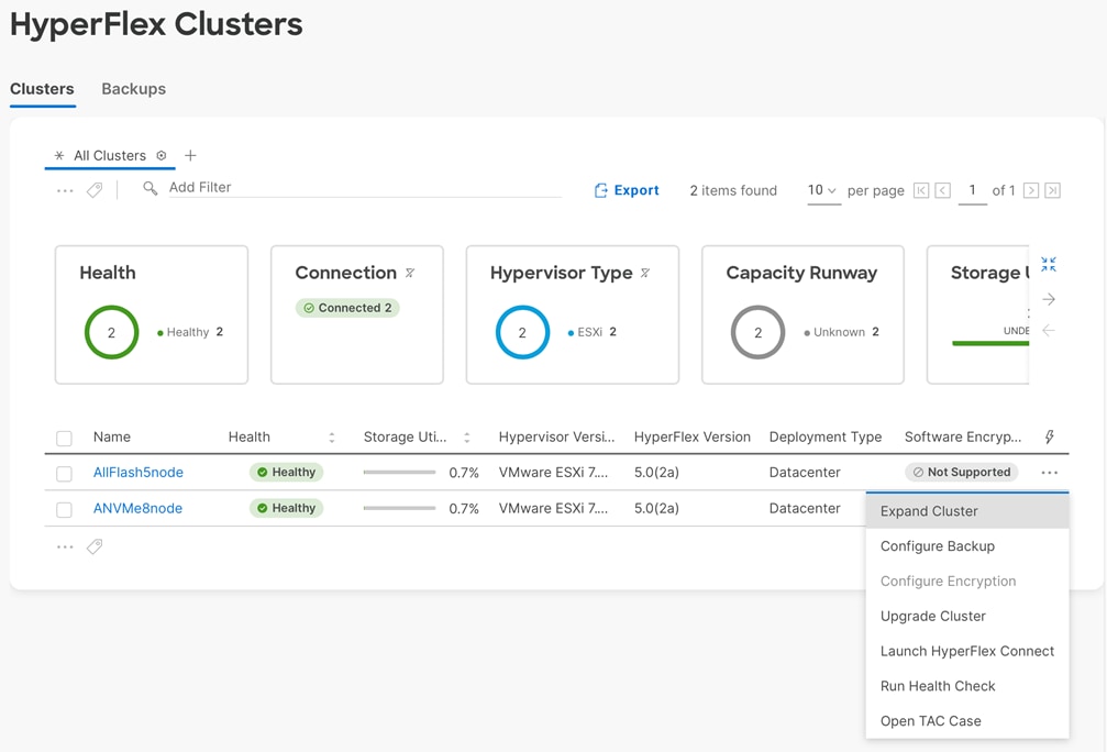
Step 3. From the list of available servers, select the server to add to the cluster, then click Next. It may be necessary to de-select the “Show Supported Nodes Only” button to see all available servers.
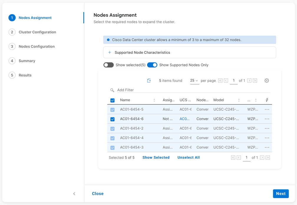
Step 4. IP addresses must be provided for the added nodes. If the IP ranges for the original cluster deployment had extra addresses in them then no changes need to be made on this screen. However, if the ranges only had enough IP addresses for the original number of servers, then additional ranges must be added. Three ranges are required; one for the ESXi hypervisor management interface(s), one for the HyperFlex controller VM(s), and one for the new nodes’ out-of-band KVM management address(es). Expand the section for Node IP Ranges. Click the + next to the existing Management Network range, then enter a starting and ending IP address for the new range to encompass the added nodes.
Step 5. Click the + next to the existing Controller VM Management Network range, then enter a starting and ending IP address for the new range to encompass the added nodes.
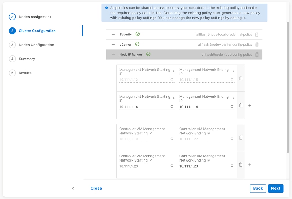
Step 6. Expand the section for Cluster Network. Click the + next to the existing KVM range, then enter a starting and ending IP address for the new range to encompass the added nodes, then click Next.
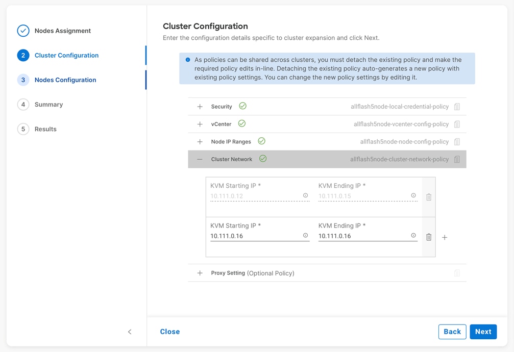
Step 7. In the Node Configuration screen, expand the additional nodes, and modify their hostnames and assigned IP addresses as needed, then click Next.
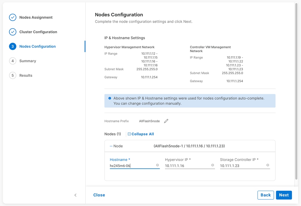
Step 8. In the Summary screen, review the changes being made, then click Validate and Deploy.
Step 9. Observe the validation and installation process. Review any warnings that are presented and click Continue.
Step 10. For converged servers delivered from the factory with the ESXi hypervisor pre-installed, the installation process should complete without any manual intervention.
Step 11. For compute-only nodes, assuming the ESXi hypervisor was not manually pre-installed, once the deployment process has associated the service profile(s) in Cisco UCS Manager, the installation will fail to find the hypervisor. Once the service profile is associated you can use the remote KVM and virtual media in Cisco UCS Manager to deploy ESXi using the Cisco HyperFlex customized ESXi ISO. If you are monitoring the deployment process, it is possible to deploy the ESXi hypervisor before the deployment job fails, otherwise the ESXi ISO can be installed and then the deployment job can be retried. To deploy the ESXi hypervisor, open Cisco UCS Manager, locate the server to be installed and click the link to open the KVM Console.
Step 12. Click Virtual Media on the left, then select vKVM-Mapped vDVD.
Step 13. Click Browse and locate the ESXi ISO installation file, such as: HX-ESXi-7.0U3-19482537-Cisco-Custom-7.3.0.6-install-only.iso, then click Map Drive.
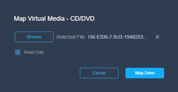
Step 14. From the Power menu on the left, select Reset System, then click confirm.
Step 15. Monitor the boot process of the server until the initial POST is completed, then press F6 to force the server into the boot device selection menu.
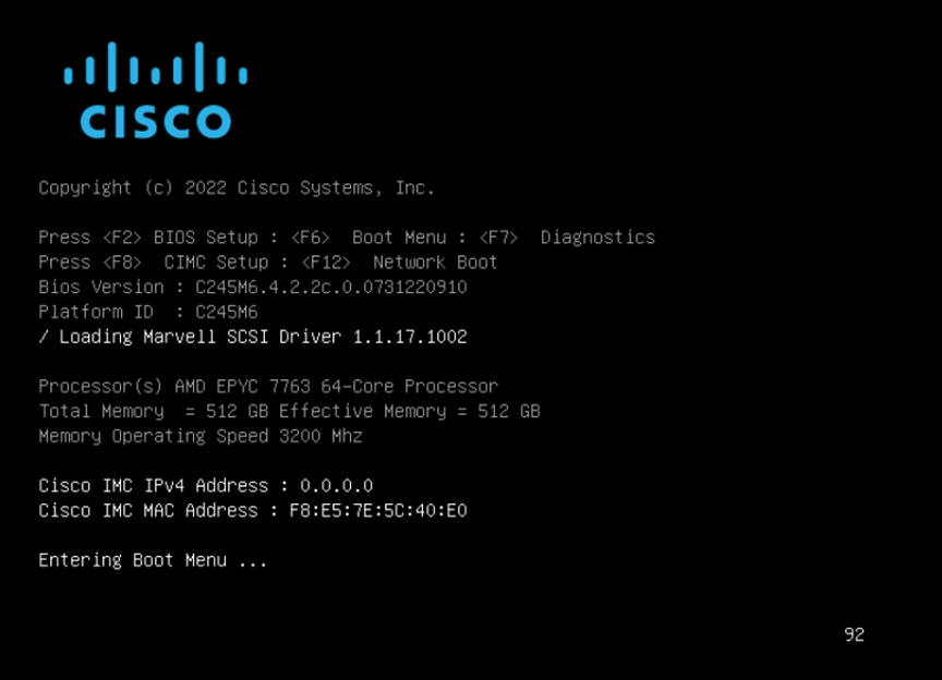
Step 16. Select UEFI: Cisco vKVM-Mapped vDVD 2.00 from the list then press Enter.
Step 17. Review the warning page contents and select “I have read the above notice and wish to continue,” then press Enter.
Step 18. Select the installation option which best matches the type of server and boot location being used for this compute-only node, then press Enter.
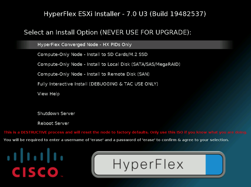
Step 19. At the prompt, enter a username of “erase” and a password of “erase,” then press Enter. The remainder of the installation of ESXi will be automated.
Step 20. After the ESXi installation is completed, if the Cisco HyperFlex expansion job has yet to time out, the job will continue with applying the hostname and networking configuration to the new node and expand the cluster. If the Cisco HyperFlex job has time out, the job can be retried by clicking on the Cisco HyperFlex cluster in Cisco Intersight. The previous failed expansion job status should be shown, and from there click Retry.
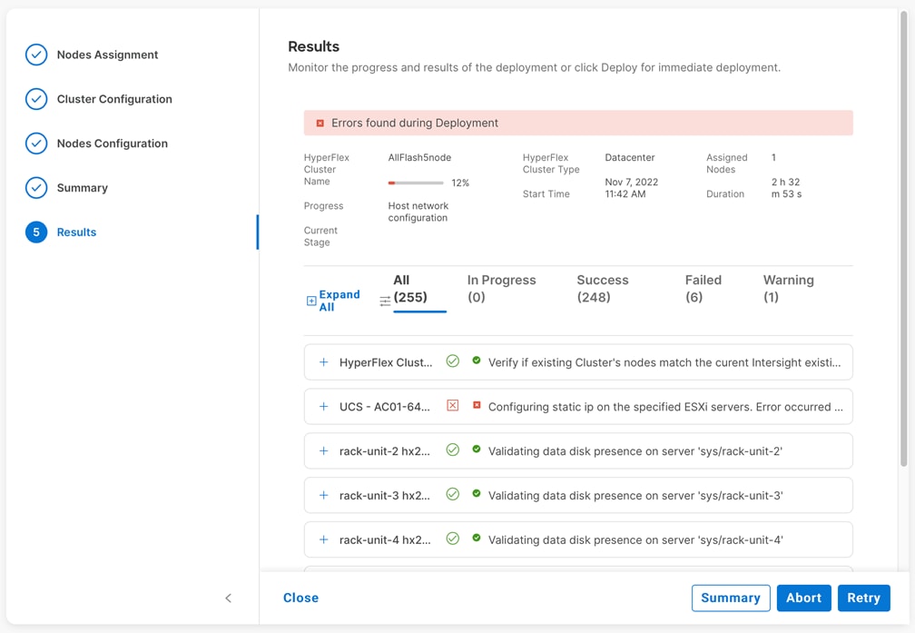
Step 21. Observe the expansion job process until it completes, then click OK.
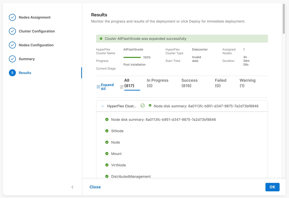
Brian Everitt, Technical Marketing Engineer, Computing Systems Product Group, Cisco Systems, Inc.
Brian is an IT industry veteran with over 24 years of experience deploying server, network, and storage infrastructures for companies around the world. During his tenure at Cisco, he has been a lead Advanced Services Solutions Architect for Microsoft solutions, virtualization, and SAP Hana on Cisco UCS. Currently his role covers solutions development for Cisco’s HyperFlex Hyperconverged Infrastructure product line, focusing on performance evaluation and product quality. Brian has earned multiple certifications from Microsoft, Cisco, and VMware.
This appendix contains the following:
● Appendix A - Cluster Capacity Calculation
● Appendix B – Cisco HyperFlex Sizer
● Appendix C - Cisco HyperFlex Profiler
● Appendix D - Cisco HyperFlex Bench
Appendix A – Cluster Capacity Calculations
A HyperFlex HX Data Platform cluster capacity is calculated as follows:
(((<capacity disk size in GB> X 10^9) / 1024^3) X <number of capacity disks per node> X <number of HyperFlex nodes> X 0.92) / replication factor
Divide the result by 1024 to get a value in TiB
The replication factor value is 3 if the HX cluster is set to RF=3, and the value is 2 if the HX cluster is set to RF=2.
The 0.92 multiplier accounts for an 8% reservation set aside on each disk by the HX Data Platform software for various internal filesystem functions.
Calculation example:
<capacity disk size in GB> = 1200 for 1.2 TB disks
<number of capacity disks per node> = 15 for an HX240c-M4SX model server
<number of HyperFlex nodes> = 8
replication factor = 3
Result: (((1200*10^9)/1024^3)*15*8*0.92)/3 = 41127.2049
41127.2049 / 1024 = 40.16 TiB
A stretched cluster maintains data identically across both halves of the cluster; therefore, it effectively doubles the replication factor. For example, the only allowed replication factor for a stretched cluster is RF2, meaning it will store 2 copies of the data on the nodes in site 1, and also store 2 copies of the data on the nodes in site 2. Because of this, the capacity of a stretched cluster is effectively reduced by 50 percent compared to RF2. The calculation above can use a value of 4 for the replication factor to determine the capacity of a stretched cluster.
Appendix B – Cisco HyperFlex Sizer
HyperFlex sizer is a cloud-based tool that can help customers and partners determine how many Cisco HyperFlex nodes are needed, and how the nodes should be configured to meet their needs for the compute resources, storage capacity and performance requirements in the datacenter. The sizing guidance for the proposed Cisco HyperFlex system is calculated according to the anticipated workload information entered by the user. The Cisco HyperFlex sizer tool is regularly updated with new features to support the currently available hardware and deployment options available in Cisco HyperFlex, and to more accurately model different workloads. This cloud application can be accessed from anywhere at the following website (CCO login required): https://hyperflexsizer.cloudapps.cisco.com
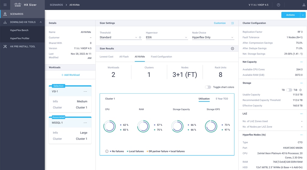
Note: The Cisco HyperFlex Sizer tool is designed to provide general guidance in evaluating the optimum solution for using selected Cisco products. The tool is not intended as a substitute for your own judgment or for that of your professional advisors.
Appendix C – Cisco HyperFlex Profiler
Also available at the https://hyperflexsizer.cloudapps.cisco.com website is an updated Cisco HyperFlex Workload Profiler. The Cisco HyperFlex Workload Profiler tool is used to capture storage usage and performance statistics from an existing VMware ESX cluster, Kubernetes cluster, or Nutanix cluster, enabling you to use that data to assist with sizing a HyperFlex cluster which would assume that workload. The workload profiler is distributed as an OVA file, which can be deployed using static or DHCP assigned addressing, on an existing VMware ESXi host. Once deployed, the profiler tool connects to an existing VMware vCenter server to gather storage statistics for the selected ESXi hosts.
Procedure 1. Capture performance data using the HyperFlex Workload Profiler
Step 1. Deploy the HyperFlex Workload Profiler VM by using the Deploy OVF Template wizard, on the chosen existing ESXi host. Assign a static IP address or use DHCP addressing as part of the deployment wizard and set the default password.
Step 2. Using a web browser, navigate to the IP address assigned or leased by the Workload Profiler VM.
Step 3. Enter the username and password, the default username is "monitoring", and use the password previously entered, then click Login.
Step 4. On first login, a wizard to add a system to be monitored will run. Enter the vCenter server name or IP, a username with administrative rights, and the password, then click Connect.
Step 5. When the vCenter server is connected, click Next to select the hosts to monitor.
Step 6. Check the box or boxes next to the hosts to poll for data, then click Next.
Step 7. Choose to generate a Quick Profile, which will not generate detailed performance data, or a Detailed Profile, then click Save.
Step 8. In the main screen, the vCenter server being polled will be listed. Click Start Profiling.
Step 9. Choose a time interval to collect data on the system, then click OK. A 30-day collection is recommended for accurate sizing activities.
Step 10. At any time during the collection polling, the data can be viewed by clicking View Collection. The data for CPU and memory utilization, and storage statistics can be viewed, as an aggregate of all hosts, one host at a time, or from a per VM perspective.
Step 11. When the collection is complete, the complete dataset can be exported as a comma-separated file, and the data can be automatically imported into the HyperFlex sizer tool to help with computing and storage sizing efforts, or otherwise analyzed to help with sizing decisions.
Appendix D – Cisco HyperFlex Bench
Also available at the https://hyperflexsizer.cloudapps.cisco.com website is the Cisco HyperFlex Bench tool. HyperFlex Bench is a tool used to perform benchmarking tests of a HyperFlex system, which utilizes the freely available Vdbench tool, in an easy-to-use web interface. Installation is done by downloading and deploying the HyperFlex Bench manager VM to the HyperFlex cluster using an OVA file. Afterwards, benchmark testing is done by connecting to the management webpage, configuring VM groups and a test profile, then executing a benchmark test. HyperFlex Bench deploys the defined load generating VMs onto the HyperFlex clustered system under test (SUT) then uses them to generate the load defined in the test profile, collecting the data via the network. HyperFlex Bench requires two networks; one publicly available network for the configuration and management of the tool, and a second private network which the load generating VMs use for their configuration and data reporting. The public network is where the HyperFlex Bench webpage is accessed, and the network where it will communicate with the managing vCenter Server of the HyperFlex system under test. The private network can be a VLAN/subnet, which is accessible via a port group for guest VMs available across the HyperFlex cluster being benchmarked. For example, the public network can use the "Storage Controller Management Network" port group, and the private network can use the "vm-network-100" port group.
Procedure 1. Run a benchmark performance test using the HyperFlex Bench
Step 1. Deploy the HyperFlex Bench VM by using the Deploy OVF Template wizard, on the chosen existing ESXi host. Assign a static IP address or use DHCP addressing as part of the deployment wizard and set the default password. Assign the public and private networks as appropriate.
Step 2. Using a web browser, navigate to the IP address assigned or leased by the HyperFlex Bench VM. Log in with the username "appadmin" and the password set during the OVA deployment. Upon the first login, a wizard will ask you to upload a copy of the Vdbench application executables and connect to the managing vCenter server.
Step 3. Upload a copy of the Vdbench application .zip file, as downloaded from Oracle. A valid login is required to download the file from the Oracle website.
Step 4. Enter the URL or IP address and the credentials to connect to the vCenter server managing this HyperFlex Bench VM and the HyperFlex cluster to be tested.
Step 5. Create a VM Group to define the VMs which will generate the load. Click VM Groups, then click Create VM Group. Enter the desired values for the HyperFlex cluster, the HX datastore, the guest VM network, the disk size, and the total number of VMs to deploy, then click Save.
Step 6. Monitor the progress of the VM Group deployment. After it is complete, the group is marked as Ready for Use, then you may continue with creating a test profile and starting a benchmark job.
Step 7. Create a custom test profile, if desired, by clicking Test Profiles, then click Create Test Profile. Enter the values for the test workload, making sure to keep the dataset size per VM under the size of the disk created per VM in the previous step, then click Save. Optionally, you can choose to upload a Vdbench configuration file for more advanced options and settings if you have one.
Step 8. Click Bench Tests, then click Create Test to create a test using either one of the included profiles, or the custom profile of your own design, then click Next.
Step 9. Select the existing VM Group you created, or optionally create a new group. Choose to include or skip disk priming, and when to start the benchmark run, then click Next. For the most accurate real-world representative results, you should always choose to prime the disks for each test.
Step 10. Review the benchmark job configuration and finally, click Start Test.
Step 11. Observe the job as it begins to ensure it properly primes the disks and the benchmark test runs.
Step 12. After the benchmark run completes, view the results of the test, and optionally view the job logs or download a report in PDF or CSV format.
For comments and suggestions about this guide and related guides, join the discussion on Cisco Community at https://cs.co/en-cvds.
CVD Program
ALL DESIGNS, SPECIFICATIONS, STATEMENTS, INFORMATION, AND RECOMMENDATIONS (COLLECTIVELY, "DE-SIGNS") IN THIS MANUAL ARE PRESENTED "AS IS," WITH ALL FAULTS. CISCO AND ITS SUPPLIERS DISCLAIM ALL WAR-RANTIES, INCLUDING, WITHOUT LIMITATION, THE WARRANTY OF MERCHANTABILITY, FITNESS FOR A PARTICULAR PURPOSE AND NONINFRINGEMENT OR ARISING FROM A COURSE OF DEALING, USAGE, OR TRADE PRACTICE. IN NO EVENT SHALL CISCO OR ITS SUPPLIERS BE LIABLE FOR ANY INDIRECT, SPECIAL, CONSEQUENTIAL, OR INCIDENTAL DAMAGES, INCLUDING, WITHOUT LIMITATION, LOST PROFITS OR LOSS OR DAMAGE TO DATA ARISING OUT OF THE USE OR INABILITY TO USE THE DESIGNS, EVEN IF CISCO OR ITS SUPPLIERS HAVE BEEN ADVISED OF THE POSSIBILITY OF SUCH DAMAGES.
THE DESIGNS ARE SUBJECT TO CHANGE WITHOUT NOTICE. USERS ARE SOLELY RESPONSIBLE FOR THEIR APPLICA-TION OF THE DESIGNS. THE DESIGNS DO NOT CONSTITUTE THE TECHNICAL OR OTHER PROFESSIONAL ADVICE OF CISCO, ITS SUPPLIERS OR PARTNERS. USERS SHOULD CONSULT THEIR OWN TECHNICAL ADVISORS BEFORE IMPLE-MENTING THE DESIGNS. RESULTS MAY VARY DEPENDING ON FACTORS NOT TESTED BY CISCO.
CCDE, CCENT, Cisco Eos, Cisco Lumin, Cisco Nexus, Cisco StadiumVision, Cisco TelePresence, Cisco WebEx, the Cisco logo, DCE, and Welcome to the Human Network are trademarks; Changing the Way We Work, Live, Play, and Learn and Cisco Store are service marks; and Access Registrar, Aironet, AsyncOS, Bringing the Meeting To You, Catalyst, CCDA, CCDP, CCIE, CCIP, CCNA, CCNP, CCSP, CCVP, Cisco, the Cisco Certified Internetwork Expert logo, Cisco IOS, Cisco Press, Cisco Systems, Cisco Systems Capital, the Cisco Systems logo, Cisco Unified Computing System (Cisco UCS), Cisco UCS B-Series Blade Servers, Cisco UCS C-Series Rack Servers, Cisco UCS S-Series Storage Servers, Cisco UCS Manager, Cisco UCS Management Software, Cisco Unified Fabric, Cisco Application Centric Infrastructure, Cisco Nexus 9000 Series, Cisco Nexus 7000 Series. Cisco Prime Data Center Network Manager, Cisco NX-OS Software, Cis-co MDS Series, Cisco Unity, Collaboration Without Limitation, EtherFast, EtherSwitch, Event Center, Fast Step, Follow Me Browsing, FormShare, GigaDrive, HomeLink, Internet Quotient, IOS, iPhone, iQuick Study, LightStream, Linksys, MediaTone, MeetingPlace, MeetingPlace Chime Sound, MGX, Networkers, Networking Academy, Network Registrar, PCNow, PIX, PowerPanels, ProConnect, ScriptShare, SenderBase, SMARTnet, Spectrum Expert, StackWise, The Fastest Way to Increase Your Internet Quotient, TransPath, WebEx, and the WebEx logo are registered trade-marks of Cisco Systems, Inc. and/or its affiliates in the United States and certain other countries. (LDW_P4)
All other trademarks mentioned in this document or website are the property of their respective owners. The use of the word partner does not imply a partnership relationship between Cisco and any other company. (0809R)