FlexPod Datacenter with Cisco UCS X-Series for SAP HANA TDI Design Guide
Available Languages
Bias-Free Language
The documentation set for this product strives to use bias-free language. For the purposes of this documentation set, bias-free is defined as language that does not imply discrimination based on age, disability, gender, racial identity, ethnic identity, sexual orientation, socioeconomic status, and intersectionality. Exceptions may be present in the documentation due to language that is hardcoded in the user interfaces of the product software, language used based on RFP documentation, or language that is used by a referenced third-party product. Learn more about how Cisco is using Inclusive Language.
- US/Canada 800-553-2447
- Worldwide Support Phone Numbers
- All Tools
 Feedback
 Feedback
In partnership with:

About the Cisco Validated Design Program
The Cisco Validated Design (CVD) program consists of systems and solutions designed, tested, and documented to facilitate faster, more reliable, and more predictable customer deployments. For more information, go to: http://www.cisco.com/go/designzone.
The FlexPod Datacenter solution is a validated approach for deploying Cisco and NetApp technologies and products to build shared private and public cloud infrastructure. Cisco and NetApp have partnered to deliver a series of FlexPod solutions that enable strategic data-center platforms. The success of the FlexPod solution is driven through its ability to evolve and incorporate both technology and product innovations in the areas of management, compute, storage, and networking.
This document explains the design details of incorporating the Cisco X-Series modular platform into the FlexPod Datacenter for SAP HANA Tailored Datacenter Integration (TDI) implementations and its ability to manage and orchestrate FlexPod components from the cloud using Cisco Intersight. Some of the key advantages of integrating Cisco UCS X-Series into the FlexPod infrastructure are:
The key benefits of this solution are:
● Simpler and programmable infrastructure: infrastructure as a code delivered through a single partner integrable open API
● Power and cooling innovations: higher power headroom and lower energy loss due to a 54V DC power delivery to the chassis
● Better airflow: midplane-free design with fewer barriers, therefore lower impedance
● Fabric innovations: PCIe/Compute Express Link (CXL) topology for heterogeneous compute and memory composability
● Innovative cloud operations: continuous feature delivery and no need for maintaining on-premise virtual machines supporting management functions
● Built for investment protections: design ready for future technologies such as liquid cooling and high-Wattage CPUs; CXL-ready
In addition to the compute-specific hardware and software innovations, the integration of the Cisco Intersight cloud platform with VMware vCenter and NetApp Active IQ Unified Manager delivers monitoring, orchestration, and workload optimization capabilities for different layers (virtualization and storage) of the FlexPod infrastructure.
If you’re interested in understanding the FlexPod design and deployment details, including the configuration of various elements of design and associated best practices, refer to Cisco Validated Designs for FlexPod, here: https://www.cisco.com/c/en/us/solutions/design-zone/data-center-design-guides/flexpod-design-guides.html.
This chapter contains the following:
● Audience
The Cisco Unified Computing System (Cisco UCS) X-Series is a brand-new modular compute system, configured and managed from the cloud. It is designed to meet the needs of modern applications and to improve operational efficiency, agility, and scale through an adaptable, future-ready, modular design. The Cisco Intersight platform is a Software-as-a-Service (SaaS) infrastructure lifecycle management platform that delivers simplified configuration, deployment, maintenance, and support.
SAP HANA in-memory database handles transactional and analytical workloads with any data type – on a single data copy. It breaks down the transactional and analytical silos in organizations, for quick decision-making, on premise and in the cloud. SAP HANA offers a multi-engine, query-processing environment that supports relational data (with both row- and column-oriented physical representations in a hybrid engine) as well as graph and text processing for semi-structured and unstructured data management within the same system. The SAP HANA TDI offers a more open and flexible way for the integration of SAP HANA into the data center with benefits like the virtualization of the SAP HANA platform or a flexible combination of multiple SAP HANA systems on the fully certified, converged infrastructure.
Powered by the Cisco Intersight cloud-operations platform, the Cisco UCS X-Series enables the next-generation cloud-operated FlexPod infrastructure that not only simplifies data-center management but also allows the infrastructure to adapt to the unpredictable needs of modern applications as well as traditional workloads. With the Cisco Intersight platform, you get all the benefits of SaaS delivery and the full lifecycle management of Intersight-connected distributed servers and integrated NetApp storage systems across data centers, remote sites, branch offices, and edge environments.
The intended audience of this document includes but is not limited to IT architects, sales engineers, field consultants, professional services, IT managers, partner engineering, and customers who are interested in learning about and deploying the FlexPod Datacenter for SAP and SAP HANA use cases, such as Scale-up system, SAP HANA scale out system with NFS or mixed protocol configurations with Linux bare metal as well as VMware ESXi installations.
This document compliments the FlexPod Datacenter with Cisco UCS X-Series, VMware 7.0 U2, and NetApp ONTAP 9.9 Design Guide: https://www.cisco.com/c/en/us/td/docs/unified_computing/ucs/UCS_CVDs/flexpod_xseries_esxi7u2_design.html and explains the design considerations and requirements for SAP HANA TDI deployments, both in virtualized as well as bare-metal scenarios.
The following design elements distinguish this version of FlexPod from previous models:
● Integration of Cisco UCS X-Series into FlexPod Datacenter for SAP HANA TDI
● Deploying and managing Cisco UCS X-Series from the cloud using Cisco Intersight
● Integration of Cisco Intersight with NetApp Active IQ Unified Manager for storage monitoring and orchestration
● Integration of Cisco Intersight with VMware vCenter for interacting with, monitoring, and orchestrating the virtualized SAP HANA environment
The FlexPod Datacenter solution with Cisco UCS X-Series and NetApp ONTAP 9.9.1 offers the following key benefits:
● Simplified cloud-based management of the solution components
● Hybrid-cloud-ready, policy-driven modular design
● Highly available and scalable platform with flexible architecture that supports various deployment models
● Easy to deploy, consume, and manage architecture, which saves time and resources required to research, procure, and integrate off-the-shelf components
● Support for component monitoring, solution automation and orchestration, and workload optimization
● Stateless architecture, providing the capability to expand and adapt to new business requirements
● Robust components capable of supporting high-performance and high bandwidth for virtualized and non-virtualized applications
● Risk reduction at each level of the design with resiliency built into each touch point
Like other FlexPod solution designs, FlexPod Datacenter with Cisco UCS X-Series, and Intersight for SAP HANA TDI is configurable according to demand and usage. You can purchase the exact infrastructure you need for your current application requirements and can then scale-up by adding more resources to the FlexPod system or scale-out by adding more FlexPod instances. By moving the management from the fabric interconnects into the cloud, the solution can respond to the speed and scale of your deployments with a constant stream of new capabilities delivered from Intersight software-as-a-service model at cloud-scale.
This chapter contains the following:
● Cisco Unified Computing System X-Series
● Cisco Nexus Switching Fabric
● Cisco MDS 9132T 32G Multilayer Fabric Switch
● Cisco Nexus Dashboard Fabric Controller
● Red Hat Ansible Automation Platform
● Red Hat Enterprise Linux for SAP Solutions
● SUSE Linux Enterprise Server for SAP Applications
● SAP Application Monitoring with AppDynamics
FlexPod Datacenter architecture is built using the following infrastructure components for compute, network, and storage:
● Cisco Unified Computing System (Cisco UCS)
● Cisco Nexus and Cisco MDS switches
● NetApp All Flash FAS (AFF), FAS and ALL SAN Array (ASA) storage systems
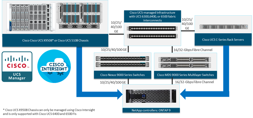
All the FlexPod components have been integrated so that you can deploy the solution quickly and economically while eliminating many of the risks associated with researching, designing, building, and deploying similar solutions from the foundation. One of the main benefits of FlexPod is its ability to maintain consistency at scale. Each of the component families shown in Figure 1 (Cisco UCS, Cisco Nexus, Cisco MDS, and NetApp controllers) offers platform and resource options to scale up or scale out the infrastructure while supporting the same features.
The FlexPod Datacenter solution with Cisco UCS X-Series in this validated design is built using following hardware components:
● Cisco UCS X9508 Chassis with up to eight Cisco UCS X210c M6 Compute Nodes
● Fourth-generation Cisco UCS 6454 Fabric Interconnects to support 10GbE, 25GbE, and 100GbE connectivity from various components
● High-speed Cisco NX-OS-based Nexus 93180YC-FX3 switching design to support up to 100GE connectivity
● Cisco MDS 9132T SAN switch to support consistent 32Gbps Fibre Channel port performance
● NetApp AFF A400 end-to-end NVMe storage with high-speed Ethernet and Fibre Channel connectivity
The software components of the solution consist of:
● Cisco Intersight platform to deploy, maintain and support the FlexPod components
● Cisco Intersight Assist Virtual Appliance to help connect NetApp ONTAP and VMware vCenter with Cisco Intersight
● NetApp ONTAP 9.12 and NetApp Active IQ Unified Manager to monitor and manage the storage for NetApp ONTAP integration with Cisco Intersight
● VMware vCenter to set up and manage the virtual infrastructure as well as Cisco Intersight integration
● VMware vSphere 7.0 U3c and later
● VMware vCenter 7.0 and later to set up and manage the virtual infrastructure and integration into Cisco Intersight
● Red Hat Enterprise Linux (RHEL) for SAP Solutions 8.2 and later
● SUSE Linux Enterprise System (SLES) for SAP Applications 15 SP2 and later
● SAP HANA 1.0 SPS 12 Revision 122.19; SAP HANA 2.0 recommended
| Tech tip |
| The solution consists of VMware certified systems as listed on the VMware hardware compatibility list (HCL) and SAP HANA supported server and storage systems, as listed on the certified and supported SAP HANA hardware directory. |
These key product highlights and features are described in the following sections.
Cisco Unified Computing System X-Series
The Cisco UCS X-Series Modular System is designed to take the current generation of the Cisco UCS platform to the next level with its future-ready design and cloud-based management. Decoupling and moving the platform management to the cloud allows Cisco UCS to respond to your feature and scalability requirements in a much faster and efficient manner. Cisco UCS X-Series state of the art hardware simplifies the data-center design by providing flexible server options. A single server type, supporting a broader range of workloads, results in fewer different data-center products to manage and maintain. The Cisco Intersight cloud-management platform manages Cisco UCS X-Series as well as integrating with third-party devices, including VMware vCenter and NetApp storage, to provide visibility, optimization, and orchestration from a single platform, thereby driving agility and deployment consistency.
The various components of the Cisco UCS X-Series are described in the following sections.
Cisco UCS X9508 Chassis
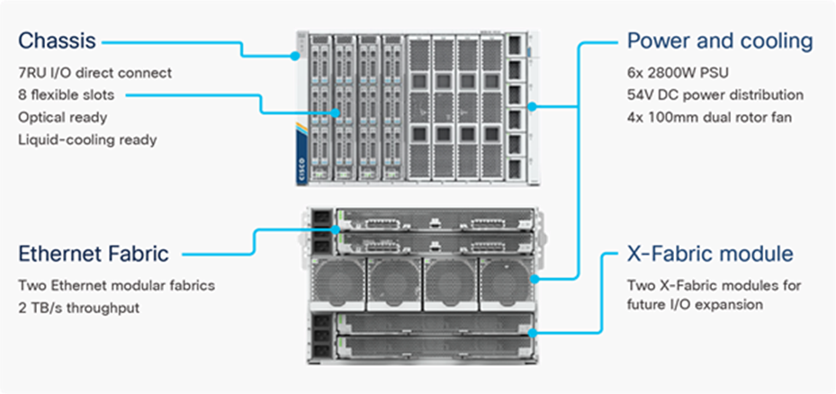
The Cisco UCS X-Series chassis is engineered to be adaptable and flexible. As seen in Figure 3, Cisco UCS X9508 chassis has only a power-distribution midplane. This midplane-free design provides fewer obstructions for better airflow. For I/O connectivity, vertically oriented compute nodes intersect with horizontally oriented fabric modules, allowing the chassis to support future fabric innovations. Cisco UCS X9508 Chassis’ superior packaging enables larger compute nodes, thereby providing more space for actual compute components, such as memory, GPU, drives, and accelerators. Improved airflow through the chassis enables support for higher power components, and more space allows for future thermal solutions (such as liquid cooling) without limitations.
The Cisco UCS X9508 7-Rack-Unit (7RU) chassis has eight flexible slots. These slots can house a combination of compute nodes and a pool of future I/O resources that may include GPU accelerators, disk storage, and nonvolatile memory. At the top rear of the chassis are two Intelligent Fabric Modules (IFMs) that connect the chassis to upstream Cisco UCS 6400 Series Fabric Interconnects. At the bottom rear of the chassis are slots ready to house future X-Fabric modules that can flexibly connect the compute nodes with I/O devices. Six 2800W Power Supply Units (PSUs) provide 54V power to the chassis with N, N+1, and N+N redundancy. A higher voltage allows efficient power delivery with less copper and reduced power loss. Efficient, 100mm, dual counter-rotating fans deliver industry-leading airflow and power efficiency, and optimized thermal algorithms enable different cooling modes to best support your environment.
Cisco UCS 9108 25G Intelligent Fabric Modules
For the Cisco UCS X9508 Chassis, the network connectivity is provided by a pair of Cisco UCS 9108 25G Intelligent Fabric Modules (IFMs). Like the fabric extenders used in the Cisco UCS 5108 Blade Server Chassis, these modules carry all network traffic to a pair of Cisco UCS 6400 Series Fabric Interconnects (FIs). IFMs also host the Chassis Management Controller (CMC) for chassis management. In contrast to systems with fixed networking components, Cisco UCS X9508’s midplane-free design enables easy upgrades to new networking technologies as they emerge making it straightforward to accommodate new network speeds or technologies in the future.

Each IFM supports eight 25Gb uplink ports for connecting the Cisco UCS X9508 Chassis to the FIs and 32 25Gb server ports for the eight compute nodes. IFM server ports can provide up to 200 Gbps of unified fabric connectivity per compute node across the two IFMs. The uplink ports connect the chassis to the UCS FIs, providing up to 400Gbps connectivity across the two IFMs. The unified fabric carries management, VM, and Fibre Channel over Ethernet (FCoE) traffic to the FIs, where management traffic is routed to the Cisco Intersight cloud operations platform, FCoE traffic is forwarded to the native Fibre Channel interfaces through unified ports on the FI (to Cisco MDS switches), and data Ethernet traffic is forwarded upstream to the data center network (via Cisco Nexus switches).
Cisco UCS 9108 100G Intelligent Fabric Modules
In the end-to-end 100Gbps Ethernet design, for the Cisco UCS X9508 Chassis, the network connectivity is provided by a pair of Cisco UCS 9108 100G Intelligent Fabric Modules (IFMs). Like the fabric extenders used in the Cisco UCS 5108 Blade Server Chassis, these modules carry all network traffic to a pair of Cisco UCS 6536 Fabric Interconnects (FIs). IFMs also host the Chassis Management Controller (CMC) for chassis management. In contrast to systems with fixed networking components, Cisco UCS X9508’s midplane-free design enables easy upgrades to new networking technologies as they emerge making it straightforward to accommodate new network speeds or technologies in the future.
Each IFM supports eight 100Gb uplink ports for connecting the Cisco UCS X9508 Chassis to the FIs and 8 100Gb server ports for the eight compute nodes. IFM server ports can provide up to 200 Gbps of unified fabric connectivity per compute node across the two IFMs. The uplink ports connect the chassis to the UCS FIs, providing up to 1600Gbps connectivity across the two IFMs. The unified fabric carries management, VM, and Fibre Channel over Ethernet (FCoE) traffic to the FIs, where management traffic is routed to the Cisco Intersight cloud operations platform, FCoE traffic is forwarded to either native Fibre Channel interfaces through unified ports on the FI (to Cisco MDS switches) or to FCoE uplinks (to Cisco Nexus switches supporting SAN switching), and data Ethernet traffic is forwarded upstream to the data center network (using Cisco Nexus switches).
Cisco UCS X210c M6 Compute Node
The Cisco UCS X9508 Chassis is designed to host up to 8 Cisco UCS X210c M6 Compute Nodes. The hardware details of the Cisco UCS X210c M6 Compute Nodes are shown in Figure 6:
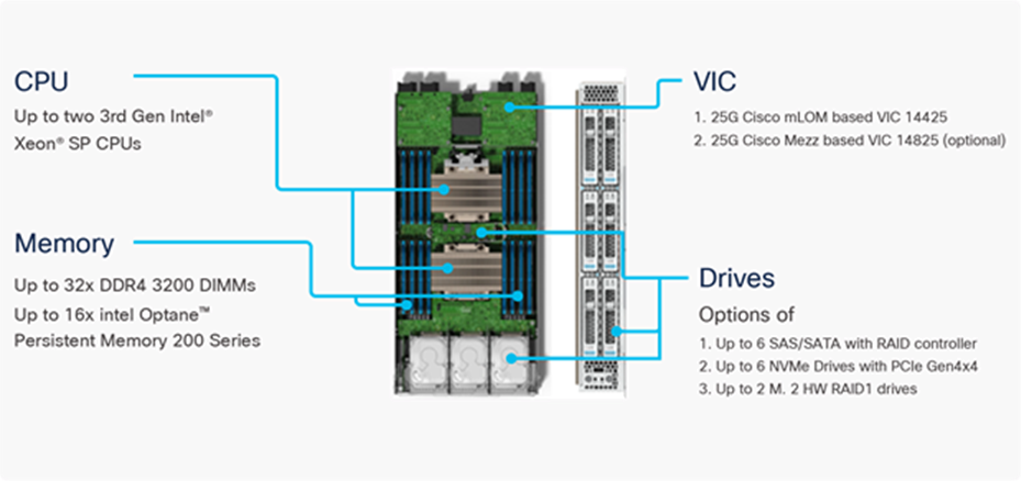
The Cisco UCS X210c M6 features:
● CPU: Up to 2x 3rd Gen Intel Xeon Scalable Processors with up to 40 cores per processor and 1.5 MB Level 3 cache per core.
● Memory: Up to 32 x 256 GB DDR4-3200 DIMMs for a maximum of 8 TB of main memory. The Compute Node can also be configured for up to 16 x 512-GB Intel Optane persistent memory DIMMs for a maximum of 12 TB of memory.
● Disk storage: Up to 6 SAS or SATA drives can be configured with an internal RAID controller, or you can configure up to 6 NVMe drives. 2 M.2 memory cards can be added to the Compute Node with RAID 1 mirroring.
● Virtual Interface Card (VIC): Up to 2 VICs including an mLOM Cisco VIC 14425 and a mezzanine Cisco VIC card 14825 can be installed in a Compute Node.
● Security: The server supports an optional Trusted Platform Module (TPM). Additional security features include a secure boot FPGA and ACT2 anticounterfeit provisions.
● For SAP HANA production system, the maximum allowed memory configuration is 2 TB of main memory for SAP BW/4HANA or BW on HANA and 4 TB of main memory for SAP S/4HANA or Suite on HANA. As of SAP HANA 2.0 SPS 04 the memory limit can be extended in combination with Intel Optane persistent memory DIMMs operated in AppDirect mode.
Cisco UCS Virtual Interface Cards (VICs)
Cisco UCS X210c M6 Compute Nodes support the following Cisco fourth-generation VIC cards:
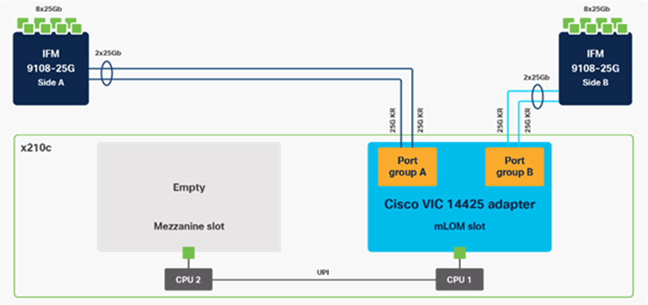
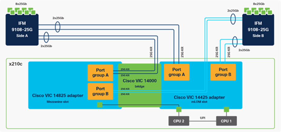
● Cisco UCS VIC 14425
Cisco UCS VIC 14425 fits the mLOM slot in the Cisco UCS X210c Compute Node and enables up to 50 Gbps of unified fabric connectivity to each of the chassis IFMs for a total of 100 Gbps of connectivity per server. Cisco UCS VIC 14425 connectivity to the IFM and up to the fabric interconnects is delivered through 4x 25-Gbps connections, which are configured automatically as 2x 50-Gbps port channels. Cisco UCS VIC 14425 supports 256 virtual interfaces (both Fibre Channel and Ethernet).
● Cisco UCS VIC 14825
The optional Cisco UCS VIC 14825 fits the mezzanine slot on the server. A bridge card (UCSX-V4-BRIDGE) extends this VIC’s 2x 50 Gbps of network connections up to the mLOM slot and out through the mLOM’s IFM connectors, bringing the total bandwidth to 100 Gbps per fabric for a total bandwidth of 200 Gbps per server.
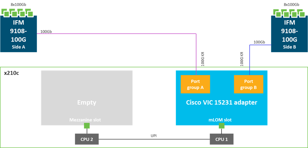
● Cisco UCS VIC 15231
Cisco UCS VIC 15231 fits the mLOM slot in the Cisco UCS X210c Compute Node and enables up to 100 Gbps of unified fabric connectivity to each of the chassis IFMs for a total of 200 Gbps of connectivity per server. Cisco USC VIC 15231 connectivity to the IFM and up to the fabric interconnects is delivered through 100Gbps. Cisco UCS VIC 15231 supports 512 virtual interfaces (both FCoE and Ethernet).
Cisco UCS Fabric Interconnects
The Cisco UCS Fabric Interconnects (FIs) provide a single point for connectivity and management for the entire Cisco UCS system. Typically deployed as an active/active pair, the system’s FIs integrate all components into a single, highly available management domain controlled by the Cisco UCS Manager or Cisco Intersight. Cisco UCS FIs provide a single unified fabric for the system, with low-latency, lossless, cut-through switching that supports LAN, SAN, and management traffic using a single set of cables.
![]()
Cisco UCS 6454 FIs utilized in the current design is a 54-port Fabric Interconnect. This single RU device includes 28 10/25 Gbps Ethernet ports, 4 1/10/25-Gbps Ethernet ports, 6 40/100-Gbps Ethernet uplink ports, and 16 unified ports that can support 10/25 Gigabit Ethernet or 8/16/32-Gbps Fibre Channel, depending on the SFP.
Note: For supporting the Cisco UCS X-Series, the fabric interconnects must be configured in Intersight Managed Mode (IMM). This option replaces the local management with Cisco Intersight cloud- or appliance-based management.
Cisco UCS 6536 Fabric Interconnects
The Cisco UCS Fabric Interconnects (FIs) provide a single point for connectivity and management for the entire Cisco Unified Computing System. Typically deployed as an active/active pair, the system’s FIs integrate all components into a single, highly available management domain controlled by Cisco Intersight. Cisco UCS FIs provide a single unified fabric for the system, with low-latency, lossless, cut-through switching that supports LAN, SAN, and management traffic using a single set of cables.
Note: Currently, the Cisco UCS 6536 does not support Cisco UCS Manager.
![]()
This single RU device includes up to 36 10/25/40/100 Gbps Ethernet ports, 16 8/16/32-Gbps Fibre Channel ports via 4 128 Gbps to 4x32 Gbps breakouts on ports 33-36. All 36 ports support breakout cables or QSA interfaces.
Note: The Cisco UCS 6536 FI currently only supports Intersight Managed Mode (IMM). This option replaces the local UCS management with Cisco Intersight cloud- or appliance-based management supporting the Cisco UCS X-Series.
The Cisco Intersight platform is a Software-as-a-Service (SaaS) infrastructure lifecycle management platform that delivers simplified configuration, deployment, maintenance, and support. The Cisco Intersight platform is designed to be modular, so you can adopt services based on your individual requirements. The platform significantly simplifies IT operations by bridging applications with infrastructure, providing visibility and management from bare-metal servers and hypervisors to serverless applications, thereby reducing costs and mitigating risk. This unified SaaS platform uses a unified Open API design that natively integrates with third-party platforms and tools.
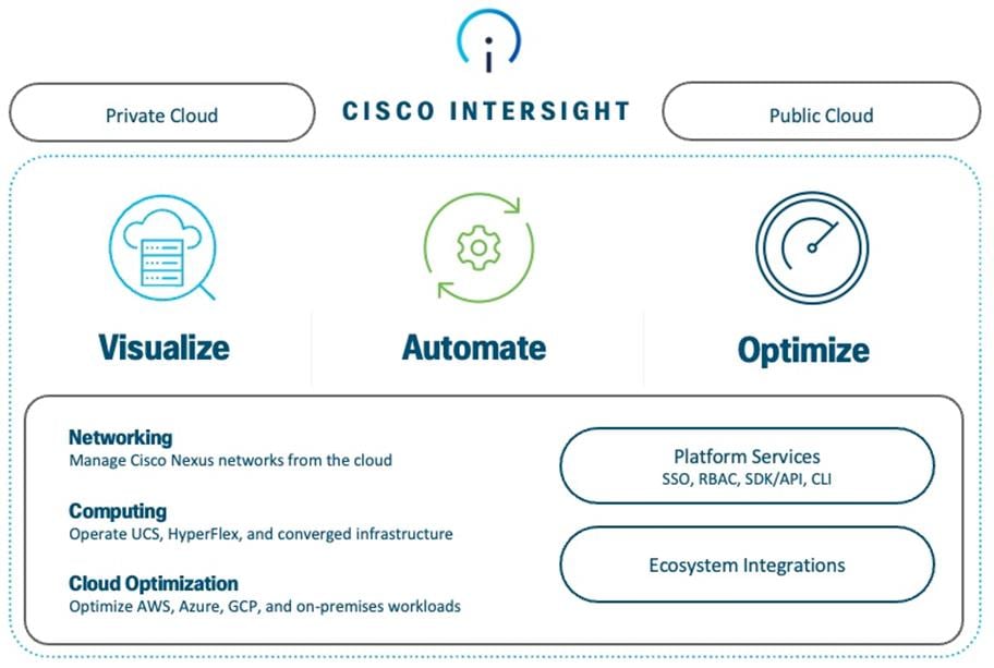
The main benefits of Cisco Intersight infrastructure services are as follows:
● Simplify daily operations by automating many daily manual tasks
● Combine the convenience of a SaaS platform with the capability to connect from anywhere and manage infrastructure through a browser or mobile app
● Stay ahead of problems and accelerate trouble resolution through advanced support capabilities
● Gain global visibility of infrastructure health and status along with advanced management and support capabilities
Cisco Intersight Virtual Appliance and Private Virtual Appliance
In addition to the SaaS deployment model running on Intersight.com, on-premises options can be purchased separately. The Cisco Intersight Virtual Appliance and Cisco Intersight Private Virtual Appliance are available for organizations that have additional data locality or security requirements for managing systems. The Cisco Intersight Virtual Appliance delivers the management features of the Cisco Intersight platform in an easy-to-deploy VMware Open Virtualization Appliance (OVA) or Microsoft Hyper-V Server virtual machine that allows you to control the system details that leave your premises. The Cisco Intersight Private Virtual Appliance is provided in a form factor specifically designed for those who operate in disconnected (air gap) environments. The Private Virtual Appliance requires no connection to public networks or back to Cisco to operate.
Cisco Intersight Assist
Cisco Intersight Assist helps you add endpoint devices to Cisco Intersight. A data center could have multiple devices that do not connect directly with Cisco Intersight. Any device that is supported by Cisco Intersight, but does not connect directly with it, will need a connection mechanism. Cisco Intersight Assist provides that connection mechanism. In FlexPod, VMware vCenter and NetApp Active IQ Unified Manager connect to Intersight with the help of Intersight Assist VM.
Cisco Intersight Assist is available within the Cisco Intersight Virtual Appliance, which is distributed as a deployable virtual machine contained within an Open Virtual Appliance (OVA) file format. More details about the Cisco Intersight Assist VM deployment configuration is covered in later sections.
Licensing Requirements
The Cisco Intersight platform uses a subscription-based license with multiple tiers. You can purchase a subscription duration of one, three, or five years and choose the required Cisco UCS server volume tier for the selected subscription duration. Each Cisco endpoint automatically includes a Cisco Intersight Base license at no additional cost when you access the Cisco Intersight portal and claim a device. You can purchase any of the following higher-tier Cisco Intersight licenses using the Cisco ordering tool:
● Intersight Infrastructure Services - Essentials: Essentials includes Intersight functionality available in UCS and HyperFlex servers along with additional features such as policy-based configuration with Server Profiles, firmware management, and evaluation of compatibility with the Hardware Compatibility List (HCL).
● Intersight Infrastructure Services – Advantage: Advantage includes all features of the Essentials tier.
● Intersight Infrastructure Services - Premier: In addition to the functionality provided in the Advantage tier, the Premier tier includes full subscription entitlement for Cisco UCS Director at no additional cost.
Servers in the Cisco Intersight managed mode require at least the Essentials license. For more information about the features provided in the various licensing tiers, see https://intersight.com/help/saas/getting_started/licensing_requirements
The Cisco Nexus 9000 Series Switches offer both modular and fixed 1/10/25/40/100 Gigabit Ethernet switch configurations with scalability up to 60 Tbps of nonblocking performance with less than five-microsecond latency, wire speed VXLAN gateway, bridging, and routing support.
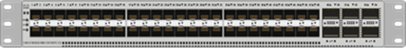
The Cisco Nexus 9000 Series Switch featured in this design is the Cisco Nexus 93180YC-FX3 configured in NX-OS standalone mode. NX-OS is a purpose-built data-center operating system designed for performance, resiliency, scalability, manageability, and programmability at its foundation. It provides a robust and comprehensive feature set that meets the demanding requirements of virtualization and automation.
The Cisco Nexus 93180YC-FX3 Switch is a 1RU switch that supports 3.6 Tbps of bandwidth and 1.2 bpps. The 48 downlink ports on the 93180YC-FX3 can support 1-, 10-, or 25-Gbps Ethernet, offering deployment flexibility and investment protection. The six uplink ports can be configured as 40- or 100-Gbps Ethernet, offering flexible migration options.
Cisco MDS 9132T 32G Multilayer Fabric Switch
The Cisco MDS 9132T 32G Multilayer Fabric Switch is the next generation of the highly reliable, flexible, and low-cost Cisco MDS 9100 Series switches. It combines high performance with exceptional flexibility and cost effectiveness. This powerful, compact one Rack-Unit (1RU) switch scales from 8 to 32 line-rate 32 Gbps Fibre Channel ports.
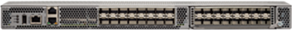
The Cisco MDS 9132T delivers advanced storage networking features and functions with ease of management and compatibility with the entire Cisco MDS 9000 family portfolio for reliable end-to-end connectivity. This switch also offers state-of-the-art SAN analytics and telemetry capabilities that have been built into this next-generation hardware platform. This new state-of-the-art technology couples the next-generation port ASIC with a fully dedicated network processing unit designed to complete analytics calculations in real time. The telemetry data extracted from the inspection of the frame headers are calculated on board (within the switch) and, using an industry-leading open format, can be streamed to any analytics-visualization platform. This switch also includes a dedicated 10/100/1000BASE-T telemetry port to maximize data delivery to any telemetry receiver, including Cisco Data Center Network Manager.
Cisco Nexus Dashboard Fabric Controller
The Cisco Nexus Dashboard Fabric Controller (NDFC), which is the evolution of Data Center Network Manager (DCNM), makes fabric management simple and reliable. It is the comprehensive management solution for all Cisco NX-OS network deployments spanning SAN fabrics, LAN fabrics, and IP fabric for media (IPFM) networking in the data center. Cisco NDFC provides management, control, automation, monitoring, visualization, and troubleshooting across Cisco Multilayer Switching (MDS) and Cisco Nexus solutions, reducing the complexities and costs of operating Cisco Nexus and storage network deployments while connecting and managing your cloud environments. Cisco NDFC is available through Cisco Data Center Networking (DCN) or NX-OS Essentials, Advantage, or Premier license and runs exclusively as a service on Cisco Nexus Dashboard.
Cisco Nexus Dashboard is managed through a web browser with various deployment options either as physical appliance or as virtual appliance like with VMware in a cluster setup with three VMware ESX virtual machines.
With the additional capability to discover and report about disk arrays in the fabric and the use of virtual machine managers, Cisco NDFC can effectively provide an end-to-end view of all communication within the data center. If you’re adopting a combination of bare-metal and virtualized servers, the capability of Cisco NDFC to provide visibility into the network, servers, and storage resources makes this tool in high demand, helping provide full control of application Service-Level Agreements (SLAs) and metrics beyond simple host and virtual machine monitoring.
Cisco Intersight Nexus Dashboard Base
The Cisco Nexus Dashboard (ND) Base provides Cisco Technical Assistance Center (TAC) Assist functions that are useful when working with the dashboard. It provides a way for you to collect technical support information across multiple devices and upload those tech supports to Cisco Cloud. The Cisco ND Base offers basic data center network assets, inventory, and status information in Cisco Intersight.
The Cisco ND Base application is connected to Cisco Intersight through a device connector that is embedded in the management controller of the Cisco NDFC platform. The device connector provides a secure way for connected Cisco NDFC to send and receive information from Cisco Intersight by using a secure Internet connection.
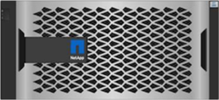
The NetApp AFF A400 offers full end-to-end NVMe support. The frontend NVMe/FC connectivity makes it possible to achieve optimal performance from an all-flash array for workloads that include artificial intelligence, machine learning, and real-time analytics as well as business-critical databases. On the back end, the A400 supports both serial-attached SCSI (SAS) and NVMe-attached SSDs, offering the versatility for you to move up from your legacy A-Series systems and satisfying the increasing interest in NVMe-based storage.
The NetApp AFF A400 offers greater port availability, network connectivity, and expandability. The NetApp AFF A400 has 10 PCIe Gen3 slots per high availability pair. The NetApp AFF A400 offers 25GbE or 100GbE, as well as 32Gb/FC and NVMe/FC network connectivity. This model was created to keep up with changing business needs and performance and workload requirements by merging the latest technology for data acceleration and ultra-low latency in an end-to-end NVMe storage system.
Note: Cisco UCS X-Series is supported with all NetApp AFF systems running NetApp ONTAP 9 release.
Build your hybrid cloud with ease
Your data fabric built by NetApp helps you simplify and integrate data management across cloud and on-premises environments to meet business demands and gain a competitive edge. With NetApp AFF A-Series, you can connect to more clouds for more data services, data tiering, caching, and disaster recovery. You can also:
● Maximize performance and reduce overall storage costs by automatically tiering cold data to the cloud with FabricPool.
● Instantly deliver data to support efficient collaboration across your hybrid cloud
● Protect your data by taking advantage of Amazon Simple Storage Service (Amazon S3) cloud resources—on premises and in the public cloud.
● Accelerate read performance for data that is shared widely throughout your organization and across hybrid cloud deployments.
● Keep data available, protected, and secure
As organizations become more data driven, the business impact of data loss can be increasingly dramatic—and costly. IT must protect data from both internal and external threats, ensure data availability, eliminate maintenance disruptions, and quickly recover from failures.
With NetApp, you can get disaster recovery and backup in the cloud while protecting data against site failure and freeing up valuable data center resources. In addition, Amazon FSx for NetApp ONTAP is now a production-certified, fully managed file service for SAP HANA. With FlexPod Hybrid cloud integration, you can automate tasks, simplify deployments, and run SAP HANA in-memory database with the flexibility of AWS-certified cloud infrastructure. For more information, refer to https://www.netapp.com/blog/new-fsx-for-ontap-features/
NetApp BlueXP
BlueXP is a unified control plane that enables you to manage your entire data landscape through one single, SaaS-delivered, point of control. Gone are the days of deploying, managing, and optimizing every environment in its own management framework and toolset, requiring specific competencies. Helps you deploy, discover, manage, and optimize data and infrastructure with the simplicity of SaaS. It combines visibility and manageability of storage instances, with data services like data protection, governance and compliance, mobility, and resource monitoring and optimization and enables multicloud operations via a unified control plane to eliminate fragmented and redundant toolsets, frameworks, lexicons, and competencies.
NetApp ONTAP 9.12.1
NetApp storage systems harness the power of ONTAP to simplify the data infrastructure from edge, core, and cloud with a common set of data services and 99.9999 percent availability. NetApp ONTAP 9 data management software from NetApp enables you to modernize your infrastructure and transition to a cloud-ready data center. ONTAP 9 has a host of features to simplify deployment and data management, accelerate and protect critical data, and make infrastructure future-ready across hybrid-cloud architectures.
NetApp ONTAP 9 is the data management software that is used with the NetApp AFF A400 all-flash storage system in this solution design. ONTAP software offers secure unified storage for applications that read and write data over block- or file-access protocol storage configurations. These storage configurations range from high-speed flash to lower-priced spinning media or cloud-based object storage. ONTAP implementations can run on NetApp engineered FAS or AFF series arrays and in private, public, or hybrid clouds (NetApp Private Storage and NetApp Cloud Volumes ONTAP). Specialized implementations offer best-in-class converged infrastructure, featured here as part of the FlexPod Datacenter solution or with access to third-party storage arrays (NetApp FlexArray virtualization). Together these implementations form the basic framework of the NetApp Data Fabric, with a common software-defined approach to data management, and fast efficient replication across systems. FlexPod and ONTAP architectures can serve as the foundation for both hybrid cloud and private cloud designs.
The following sections provide an overview of how ONTAP 9 is an industry-leading data management software architected on the principles of software defined storage.
Read more about all the capabilities of ONTAP data management software here: https://www.netapp.com/us/products/data-management-software/ontap.aspx.
For more information on new features and functionality in latest ONTAP software, refer to the ONTAP release notes: ONTAP 9 Release Notes (netapp.com)
NetApp Storage Virtual Machine
A NetApp ONTAP cluster serves data through at least one, and possibly multiple, storage virtual machines (SVMs). An SVM is a logical abstraction that represents the set of physical resources of the cluster. Data volumes and network LIFs are created and assigned to an SVM and can reside on any node in the cluster to which that SVM has access. An SVM can own resources on multiple nodes concurrently, and those resources can be moved non-disruptively from one node in the storage cluster to another. For example, a NetApp FlexVol flexible volume can be non-disruptively moved to a new node and aggregate, or a data LIF can be transparently reassigned to a different physical network port. The SVM abstracts the cluster hardware, and therefore it is not tied to any specific physical hardware.
An SVM can support multiple data protocols concurrently. Volumes within the SVM can be joined to form a single NAS namespace. The namespace makes all of the SVM's data available through a single share or mount point to NFS and CIFS clients. SVMs also support block-based protocols, and LUNs can be created and exported by using iSCSI, FC, and FCoE. Any or all of these data protocols can be used within a given SVM. Storage administrators and management roles can be associated with an SVM, offering higher security and access control. This security is important in environments that have more than one SVM and when the storage is configured to provide services to different groups or sets of workloads. In addition, you can configure external key management for a named SVM in the cluster. This is a best practice for multitenant environments in which each tenant uses a different SVM (or set of SVMs) to serve data.
Storage Efficiencies
Storage efficiency is a primary architectural design point of ONTAP data management software. A wide array of features enables you to store more data that uses less space. In addition to deduplication and compression, you can store your data more efficiently by using features such as unified storage, multitenancy, thin provisioning, and by using NetApp Snapshot technology.
Starting with ONTAP 9, NetApp guarantees that the use of NetApp storage efficiency technologies on AFF systems reduces the total logical capacity used to store your data up to a data reduction ratio of 7:1, based on the workload. This space reduction is enabled by a combination of several different technologies, including deduplication, compression, and compaction.
Compaction, which was introduced in ONTAP 9, is the latest patented storage efficiency technology released by NetApp. In the NetApp WAFL file system, all I/O takes up 4KB of space, even if it does not actually require 4KB of data. Compaction combines multiple blocks that are not using their full 4KB of space together into one block. This single block can be more efficiently stored on the disk to save space. These storage efficiencies improve the ability of ONTAP to store more data in less space, reducing storage costs and maximizing the effective capacity of your storage system.
NetApp Volume Encryption(NVE) and NetApp Aggregate Encryption (NAE)
NetApp Volume Encryption is a software-based, data-at-rest encryption solution that is FIPS 140-2 compliant. NVE allows ONTAP to encrypt data for each volume for granularity. NAE, is an outgrowth of NVE; it allows ONTAP to encrypt data for each volume, and the volumes can share keys across the aggregate. NVE and NAE enable you to use storage efficiency features that would be lost with encryption at the application layer. For greater storage efficiency, you can use aggregate deduplication with NAE.
Here’s how the process works: The data leaves the disk encrypted, is sent to RAID, is decrypted by the CryptoMod, and is then sent up the rest of the stack. This process is illustrated in Figure 17.
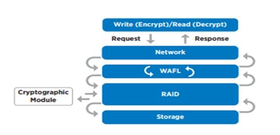
To view the latest security features for ONTAP 9, go to: Security Features in ONTAP 9 | NetApp.
ONTAP Rest API
ONTAP Rest API enables you to automate the deployment and administration of your ONTAP storage systems using one of several available options. The ONTAP REST API provides the foundation for all the various ONTAP automation technologies.
Beginning with ONTAP 9.6, ONTAP includes an expansive workflow-driven REST API that you can use to automate deployment and management of your storage. In addition, NetApp provides a Python client library, which makes it easier to write robust code, as well as support for ONTAP automation based on Ansible.
FlexClone
NetApp FlexClone technology enables instantaneous point-in-time copies of a FlexVol volume without consuming any additional storage until the cloned data changes from the original. FlexClone volumes add extra agility and efficiency to storage operations. They take only a few seconds to create and do not interrupt access to the parent FlexVol volume. FlexClone volumes use space efficiently, applying the ONTAP architecture to store only data that changes between the parent and clone. FlexClone volumes are suitable for testing or development environments, or any environment where progress is made by locking-in incremental improvements. FlexClone volumes also benefit any business process where you must distribute data in a changeable form without endangering the integrity of the original.
SnapMirror (Data Replication)
NetApp SnapMirror is an asynchronous replication technology for data replication across different sites, within the same data center, on-premises datacenter to cloud, or cloud to on-premises datacenter. SnapMirror Synchronous (SM-S) offers volume granular, zero data loss protection. It extends traditional SnapMirror volume replication to synchronous mode meeting zero recovery point objective (RPO) disaster recovery and compliance objectives. ONTAP 9.7 extends support for SnapMirror Synchronous to application policy-based replication providing a simple and familiar configuration interface that is managed with the same tools as traditional SnapMirror. This includes ONTAP CLI, NetApp ONTAP System Manager, NetApp Active IQ Unified Manager, and NetApp Manageability SDK.
NetApp’s Solutions to Ransomware
It is important for ransomware detection to occur as early as possible so that you can prevent its spread and avoid costly downtime. NetApp offers a layered defense approach with ONTAP software and its native detection and recovery tools. This section summarizes various features and tools that NetApp offers to detect, alert, and recover from ransomware attacks.
● NetApp Active IQ (AIQ) checks NetApp ONTAP systems for adherence to NetApp configuration best practices such as enabling FPolicy.
● NetApp Active IQ Unified Manager (AIQUM) generates alerts for abnormal growth of NetApp Snapshot copies or storage efficiency loss, which can indicate potential ransomware attacks.
● ONTAP System Manager enables to look at Snapshot percent change or storage efficiency savings in real time.
● Autonomous Ransome ware Protection. NetApp ONTAP 9.10.1 and later comes with anti-ransomware feature that leverages built-in on-box machine learning (ML) that looks at volume workload activity and data entropy to automatically detect ransomware. In ONTAP 9.11.1, this feature has been enhanced with an enhanced analytics engine that catches newer variations of ransomware that manipulates data entropy and file extensions. This feature can be integrated with Cloud Secure to track the status of on-box protection in Cloud Insight dashboard. This feature is supported on FSx and CVO as well. In ONTAP 9.12.1, ARP screening profile is transferred as part of the NetApp SnapMirror replication, resulting in ransomware protection on secondary storage.
● NetApp Native FPolicy is a file-access notification framework that is used to monitor and to manage file access over the NFS or SMB/CIFS protocol. This Zero trust engine is built around the concept of "not to trust and always verify". FPolicy helps you block unwanted files from being stored on the NetApp storage device. This feature can be leveraged to block known ransomware file extensions. With ONTAP 9.12.1, FPolicy can now be activated with a simple one-click in System Manager or NetApp BlueXP. This feature protects against thousands of known, common ransomware extensions that are used for typical ransomware attacks.
● FPolicy external mode in ONTAP uses UBA (sometimes referred to as User and Entity Behavior Analytics, or UEBA) as the key to stopping a zero-day ransomware attack. UBA tracks user's and group's data access patterns and report any deviation in pattern. UBA can also deny access to files when users do something outside their usual pattern. UBA requires an external mode FPolicy server.
Note: Cloud Insights with Cloud Secure is NetApp's own external mode FPolicy server.
● NetApp SnapShot copies. Snapshot is a read-only image of a volume that captures the state of a file system at a point in time. These copies help protect data with no effect on system performance and, at the same time, do not occupy a lot of storage space. Scheduled Snapshots taken would come in handy when you need to restore the data after an attack.
● NetApp SnapLock is a key component for enterprise data protection and data resiliency against ransomware. It provides a special immutable volume in which the data can be stored and committed to a non-erasable, non-rewritable state for a specific retention period. User’s production data residing in FlexGroups can also be created as SnapLock volumes, enabling higher performance and massive scale for indelible worm-protected data.
NetApp Cloud Secure
NetApp Cloud Secure is a feature of NetApp Cloud Insights, an offering from NetApp Blue-XP. It provides centralized visibility and control of all corporate data access across on-premises and cloud environments to ensure security and compliance goals are met. It reports access activity from insiders, outsiders, ransomware attacks, and rogue users. It profiles users and groups for normal data access patterns and if a risky behavior is detected, it alerts you and automatically takes a Snapshot copy which can be used to recover quickly.
Unlike perimeter security tools, which assume that insiders are trusted, NetApp Cloud Secure assumes zero trust for everyone. All activities on the supervised shares are monitored in real time and the data is used to automatically identify the working communities of all users.
Along with the ability to audit all document access, NetApp Cloud Secure helps you to ensure compliance with regulatory requirements.
NetApp Cloud Secure performs four major functions:
● Monitor user activity
● Detect anomalies and identify potential attacks
● Automated response policies
● Forensics and user audit reporting
It provides a graphical interface to slice and dice activity data to perform data breach investigations and generate user data access audit reports. It allows multiple views of file data activities by user, time, activity type, and file attributes.
For more information about NetApp ransomware protection refer to https://bluexp.netapp.com/ransomware-protection.
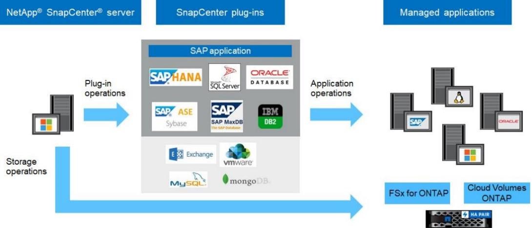
NetApp SnapCenter is a NetApp next-generation data protection software for tier 1 enterprise applications. SnapCenter Software is a simple, centralized, scalable platform that provides application-consistent data protection for applications, databases, host file systems, and virtual machines (VMs) running on ONTAP systems anywhere in the Hybrid Cloud.
SnapCenter leverages NetApp Snapshot, SnapRestore, FlexClone, SnapMirror, and SnapVault technologies to provide the following:
● Fast, space-efficient, application-consistent, disk-based backups
● Rapid, granular restore and application-consistent recovery
● Quick, space-efficient cloning
SnapCenter enables seamless integration with Oracle, Microsoft, SAP, MongoDB and VMware across FC, iSCSI, and NAS protocols. This integration enables IT organizations to scale their storage infrastructure, meet increasingly stringent SLA commitments, and improve the productivity of administrators across the enterprise.
Starting with SnapCenter 4.3, SnapCenter Server has been decoupled from the SnapCenter plugin for VMware vSphere and is no longer required to backup the VM’s and datastores. VM and datastore backup functions have been moved exclusively to the SnapCenter plugin for VMware vSphere which was deployed as part of this design. SnapCenter server is still required for application-level VM backups such as for Microsoft SQL Server, Oracle, and SAP HANA.
The SnapCenter platform is based on a multitiered architecture that includes a centralized management server (SnapCenter Server) and a SnapCenter plug-in host.
Figure 18 illustrates the high-level architecture of the NetApp SnapCenter Server.
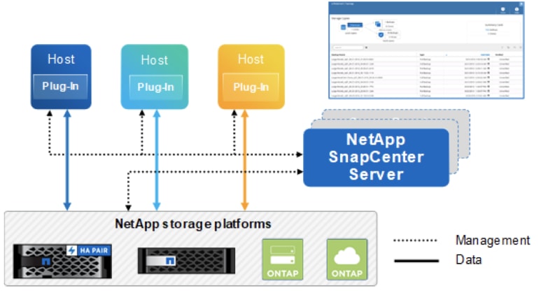
The SnapCenter Server includes a web server, a centralized HTML5-based user interface, PowerShell cmdlets, REST APIs, and the SnapCenter repository.
SnapCenter enables load balancing, high availability, and horizontal scaling across multiple SnapCenter Servers within a single user interface. You can accomplish high availability by using Network Load Balancing (NLB) and Application Request Routing (ARR) with SnapCenter. For larger environments with thousands of hosts, adding multiple SnapCenter Servers can help balance the load.
The SnapCenter Server can push out plug-ins to remote hosts. These plug-ins are used to interact with an application, a database, or a file system. The SnapCenter Server and plug-ins communicate with the host agent using HTTPS. Usually, the plug-ins must be present on the remote host so that application-level or database-level commands can be issued from the same host where the application or database is running.
To manage the plug-ins and the interaction between the SnapCenter Server and the plug-in host, SnapCenter uses SM Service. SM service is a NetApp SnapManager web service running on top of Windows Server internet information services (IIS) on the SnapCenter Server. SM Service takes all client requests such as backup, restore, and clone.
The SnapCenter Server communicates those requests to SMCore, which is a service that runs co-located within the SnapCenter Server and remote servers. SMCore plays a significant role in coordinating with the SnapCenter plug-ins package for Windows.
SnapCenter Features
SnapCenter enables you to create application-consistent Snapshot copies and to complete data protection operations, including Snapshot copy-based backup, clone, restore, and backup-verification operations. SnapCenter provides a centralized management environment, and it uses role-based access control (RBAC) to delegate data protection and management functions to individual application users across the SnapCenter Server and Windows hosts.
SnapCenter includes the following key features:
● A unified and scalable platform across applications and database environments with virtual and nonvirtual storage powered by the SnapCenter Server
● Consistency of features and procedures across plug-ins and environments supported by the SnapCenter GUI
● RBAC for security and centralized role delegation
● Application-consistent Snapshot copy management, restore, clone, and backup verification support from both primary and secondary destinations (NetApp SnapMirror and NetApp SnapVault technology)
● Remote package installation from the SnapCenter GUI
● Nondisruptive, remote upgrades
● A dedicated SnapCenter repository for faster data retrieval
● Load balancing that is implemented by using Microsoft Windows network load balancing (NLB) and application request routing (ARR) with support for horizontal scaling
● Centralized scheduling and policy management to support backup and clone operations
● Centralized reporting, monitoring, and dashboard views
● SnapCenter 4.7 support for data protection for VMware VMs, SQL Server databases, Oracle databases, MySQL, SAP HANA, MongoDB, and Microsoft Exchange
SAP HANA Data Protection with SnapCenter
The FlexPod solution can be extended with additional software and hardware components to cover data protection, backup and recovery, and disaster recovery operations. The following chapter provides a high-level overview of how to enhance SAP HANA backup and disaster recovery using the NetApp SnapCenter plug-In for SAP HANA.
More details on the setup and configuration of SnapCenter for backup and recovery or disaster recovery operations can be found in the following technical reports:
● SAP HANA Backup and Recovery with SnapCenter
● SAP HANA Disaster Recovery with Asynchronous Storage Replication
Storage-based Snapshot backups are a fully supported and integrated backup method available for SAP HANA.
Storage-based Snapshot backups are implemented with the NetApp SnapCenter plug-in for SAP HANA, which creates consistent Snapshot backups by using the interfaces provided by the SAP HANA database. SnapCenter registers the Snapshot backups in the SAP HANA backup catalog so that they are visible within the SAP HANA studio or cockpit and can be selected for restore and recovery operations.
Snapshot copies created within primary storage can be replicated to the secondary backup storage by using NetApp SnapMirror technology controlled by SnapCenter. Different backup retention policies can be defined for backups held on the primary storage and to those backups held on the secondary storage. The SnapCenter Plug-In for SAP HANA manages the retention of Snapshot copy-based data backups and log backups, including housekeeping of the backup catalog. The SnapCenter plug-in for SAP HANA also allows the execution of a block integrity check of the SAP HANA database by executing a file-based backup.
Storage-based Snapshot backups provide significant advantages when compared to file-based backups. Advantages include the following:
● Rapid backup (less than a minute)
● Faster restore on the storage layer (less than a minute)
● No performance effect on the SAP HANA database host, network, or storage during backup
● Space-efficient and bandwidth-efficient replication to secondary storage based on block changes
SAP HANA Disaster Recovery with Asynchronous Storage Replication
SAP HANA disaster recovery can be performed either on the database layer by using SAP system replication or on the storage layer by using storage replication technologies. This section provides an overview of disaster recovery solutions based on asynchronous storage replication.
The same SnapCenter plug-in that is described in section SAP HANA Backup, and is also used for the asynchronous mirroring solution. A consistent Snapshot image of the database at the primary site is asynchronously replicated to the disaster recovery site with SnapMirror.
High-level Architecture Description
Figure 19 shows a high-level overview of the data protection architecture.
For an offsite backup and disaster recovery solution, the following additional hardware and software components are required:
● A Windows host to run SnapCenter server software
● Offsite backup storage to replicate backups from primary storage to a secondary storage system
● Disaster recovery storage to replicate backups from primary storage to a disaster recovery site
● AWS FSx for NetApp ONTAP and Cloud Volumes ONTAP at different Cloud provides can be used as backup targets and as disaster recovery site as well
The SnapCenter Server must be able to communicate with the SVMs that are used at the primary (within the FlexPod instance), the offsite backup location, and the disaster recovery storage.
The primary storage must have a network connection to the offsite storage and the disaster recovery storage. A storage cluster peering must be established between the primary storage, the offsite storage, and the disaster recovery storage.
The SnapCenter Server must have a network connection to the SAP HANA database hosts to deploy the HANA plug-in and to communicate with the plug-in after deployment. As an alternative, the HANA plug-in can also be deployed at the FlexPod management server. See SAP HANA Backup and Recovery with SnapCenter for more details on the deployment options for the HANA plug-in.
SAP HANA System Replication - Backup and Recovery with SnapCenter
SAP HANA System Replication is often used as a high availability or disaster recovery solution for SAP HANA databases. SAP HANA System Replication offers different modes of operation that you can use depending on your use case or availability requirements. The single node SAP HANA system hosted on a Cisco X-series node can have the replication configured with a dedicated secondary SAP HANA host for high availability purpose within the same site or for disaster recovery over long distances. In either case, the backups must be able to be taken regardless of which SAP HANA host is primary or secondary. For more details on SnapCenter configuration options for system replication, go to: https://docs.netapp.com/de-de/netapp-solutions-sap/backup/saphana-sr-scs-sap-hana-system-replication-overview.html.
NetApp ONTAP Tools for VMware vSphere
NetApp ONTAP tools for VMware vSphere is a unified appliance that includes vSphere Storage Console (VSC),VASA Provider and SRA Provider. This vCenter web client plug-in that provides Context sensitive menu to provision traditional datastores and Virtual Volume (vVol) datastore.
NetApp ONTAP tools provides visibility into the NetApp storage environment from within the VMware vSphere web client. VMware administrators can easily perform tasks that improve both server and storage efficiency while still using role-based access control to define the operations that administrators can perform. It includes enhanced REST APIs that provide vVols metrics for SAN storage systems using NetApp ONTAP 9.7 and later. NetApp OnCommand API Services is no longer required to get metrics for NetApp ONTAP systems 9.7 and later.
To download ontap tools for VMware vSphere, go to: https://mysupport.netapp.com/site/products/all/details/otv/downloads-tab.
NetApp NFS Plug-in for VMware VAAI
The NetApp NFS Plug-in for VMware vStorage APIs - Array Integration (VAAI) is a software library that integrates the VMware Virtual Disk Libraries that are installed on the ESXi host. The VMware VAAI package enables the offloading of certain tasks from the physical hosts to the storage array. Performing those tasks at the array level can reduce the workload on the ESXi hosts.
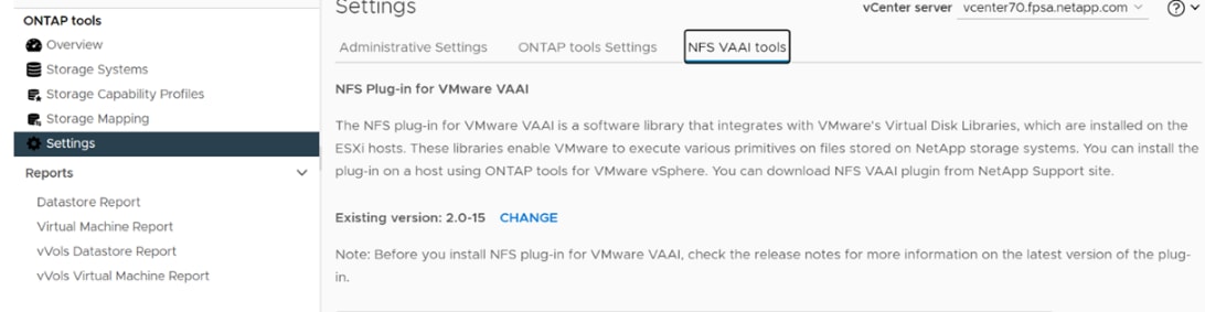
The copy offload feature and space reservation feature improve the performance of VSC operations. The NetApp NFS Plug-in for VAAI is not shipped with VSC, but you can install it by using VSC. You can download the plug-in installation package and obtain the instructions for installing the plug-in from the NetApp Support site.
For more information about the NetApp VSC for VMware vSphere, see the NetApp Virtual Infrastructure Management Product Page.
Note: While vVol datastores with FCP are supported with virtualized SAP HANA, the preferred option to connect storage to virtual machines is with NFS directly out of the guest operating system. For more information, go to: https://docs.netapp.com/us-en/netapp-solutions-sap/bp/saphana_aff_fc_sap_hana_using_vmware_vsphere.html.
NetApp SnapCenter Plug-In for VMware vSphere
NetApp SnapCenter Plug-in for VMware vSphere enables VM-consistent and crash-consistent backup and restore operations for VMs and datastores from the vCenter server. The NetApp SnapCenter plug-in is deployed as a virtual appliance, and it integrates with the vCenter server web client GUI.
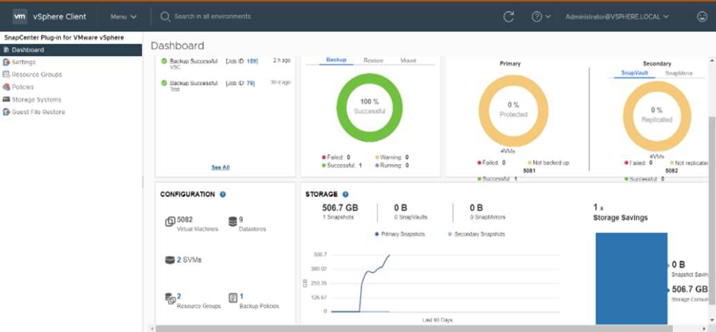
Here are some of the functionalities provided by the SnapCenter plug-in to help protect your VMs and datastores:
● Backup VMs, virtual machine disks (VMDKs), and datastores
◦ You can back up VMs, underlying VMDKs, and datastores. When you back up a datastore, you back up all the VMs in that datastore.
◦ You can create mirror copies of backups on another volume that has a SnapMirror relationship to the primary backup or perform a disk-to-disk backup replication on another volume that has a NetApp SnapVault relationship to the primary backup volume.
◦ Backup operations are performed on all the resources defined in a resource group. If a resource group has a policy attached and a schedule configured, then backups occur automatically according to the schedule.
● Restore VMs and VMDKs from backups
◦ You can restore VMs from either a primary or secondary backup to the same ESXi server. When you restore a VM, you overwrite the existing content with the backup copy that you select.
◦ You can restore one or more VMDKs on a VM to the same datastore. You can restore existing
● VMDKs, or deleted or detached VMDKs from either a primary or a secondary backup
● You can attach one or more VMDKs from a primary or secondary backup to the parent VM (the same VM that the VMDK was originally associated with) or an alternate VM. You can detach the VMDK after you have restored the files you need.
● You can restore a deleted VM from a datastore primary or secondary backup to an ESXi host that you select.
Note: For application-consistent backup and restore operations, the NetApp SnapCenter Server software is required.
Note: For additional information, requirements, licensing, and limitations of the NetApp SnapCenter Plug-In for VMware vSphere, see the NetApp Product Documentation.
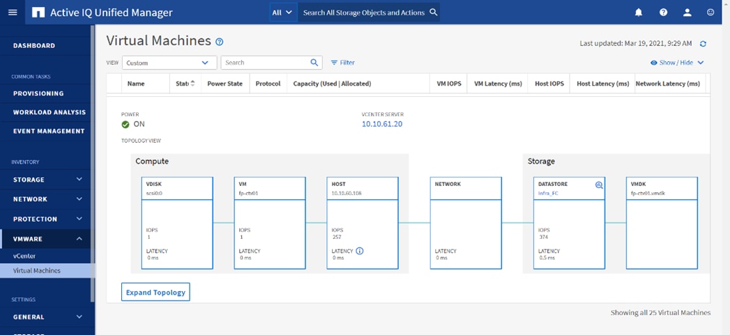
NetApp Active IQ Unified Manager
NetApp Active IQ Unified Manager (Unified Manager) is a comprehensive monitoring and proactive management tool for NetApp ONTAP systems to help manage the availability, capacity, protection, and performance risks of your storage systems and virtual infrastructure. You can deploy NetApp Active IQ Unified Manager on a Linux server, on a Windows server, or as a virtual appliance on a VMware host.
Active IQ Unified Manager enables monitoring your NetApp ONTAP storage clusters, VMware vCenter server and VMs from a single redesigned, intuitive interface that delivers intelligence from community wisdom and AI analytics. It provides comprehensive operational, performance, and proactive insights into the storage environment and the VMs running on it. When an issue occurs on the storage or virtual infrastructure, NetApp Active IQ Unified Manager can notify you about the details of the issue to help with identifying the root cause.
NetApp Active IQ Unified Manager enables to manage storage objects in your environment by associating them with annotations. You can create custom annotations and dynamically associate clusters, SVMs, and volumes with the annotations through rules.
The VM dashboard gives you a view into the performance statistics for the VM so that you can investigate the entire I/O path from the vSphere host down through the network and finally to the storage. Some events also provide remedial actions that can be taken to rectify the issue. You can also configure custom alerts for events so that when issues occur, you are notified through email and SNMP traps.
VMware vSphere is a virtualization platform for holistically managing large collections of infrastructures (resources including CPUs, storage, and networking) as a seamless, versatile, and dynamic operating environment. Unlike traditional operating systems that manage an individual machine, VMware vSphere aggregates the infrastructure of an entire data center to create a single powerhouse with resources that can be allocated quickly and dynamically to any application in need.
Running SAP HANA TDI virtualized on vSphere delivers a software-defined deployment architecture to SAP HANA customers, which will allow easy transition between private, hybrid or public cloud environments.
Using the SAP HANA platform with VMware vSphere virtualization infrastructure provides an optimal environment for achieving a unique, secure, and cost-effective solution and provides benefits physical deployments of SAP HANA cannot provide, such as:
● Higher service-level agreements (SLAs) by leveraging vSphere vMotion to live migrate running SAP HANA instances to other vSphere host systems before hardware maintenance or host resource constraints.
● Standardized high availability solution based on vSphere High Availability.
● Built-in multitenancy support via SAP HANA system encapsulation in a virtual machine (VM).
● Easier hardware upgrades or migrations due to abstraction of the hardware layer.
● Higher hardware utilization rates.
● Automation, standardization and streamlining of IT operation, processes, and tasks.
● Cloud readiness due to software-defined data center (SDDC) SAP HANA deployments.
These features available exclusively with virtualization, lower the total cost of ownership and ensure the best operational performance and availability. FlexPod for SAP HANA TDI fully supports SAP HANA and related software in production environments, as well as SAP HANA features such as SAP HANA multitenant database containers (MDC) or SAP HANA system replication (HSR).
For more information about SAP HANA on VMware vSphere, see: https://launchpad.support.sap.com/#/notes/2937606
VMware vSphere vCenter
VMware vCenter Server provides unified management of all hosts and VMs from a single console and aggregates performance monitoring of clusters, hosts, and VMs. VMware vCenter Server gives administrators a deep insight into the status and configuration of compute clusters, hosts, VMs, storage, the guest OS, and other critical components of a virtual infrastructure. VMware vCenter manages the rich set of features available in a VMware vSphere environment.
Cisco Intersight uses the device connector running within the Cisco Intersight Assist virtual appliance to communicate with the VMware vCenter, NetApp storage, and Cisco Nexus switches.
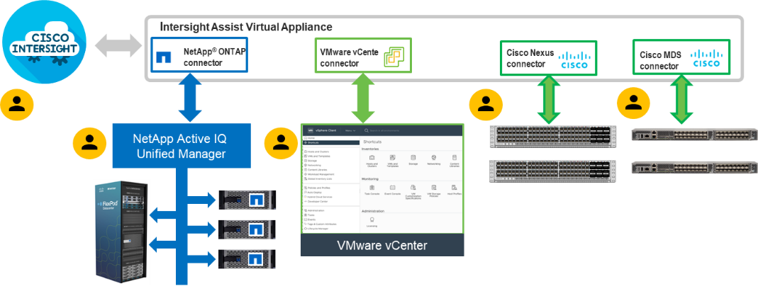
The device connector provides a secure way for connected targets to send information and receive control instructions from the Cisco Intersight portal using a secure internet connection. The integration brings the full value and simplicity of Cisco Intersight infrastructure management service to VMware hypervisor and NetApp ONTAP data storage environments.
Enterprise SAN and NAS workloads can benefit equally from the integrated management solution. The integration architecture enables you to use new management capabilities with no compromise in your existing VMware, NetApp ONTAP, or switch operations. IT users will be able to manage heterogeneous infrastructure from a centralized Cisco Intersight portal. At the same time, the IT staff can continue to use VMware vCenter, NetApp Active IQ Unified Manager, and Cisco Switch Interfaces for comprehensive analysis, diagnostics, and reporting of virtual, storage, and switching environments. The functionality provided through this integration is explained in the upcoming solution design section.
Red Hat Ansible Automation Platform
Red Hat Ansible Automation Platform provides an enterprise framework for building and operating IT automation across an organization. It is simple and powerful, allowing users to easily manage various physical devices within FlexPod including the provisioning of Cisco UCS bare metal servers, Cisco Nexus and MDS switches, NetApp A400 AFF storage array and VMware vSphere. Using Ansible’s Playbook-based automation provides a more secure and stable foundation for deploying end-to-end infrastructure automation.
This solution offers Ansible Playbooks that are made available from a GitHub repository that you can access to automate the FlexPod deployment.
Red Hat Enterprise Linux for SAP Solutions
Red Hat Enterprise Linux for SAP Solutions is an SAP specific offering, tailored to the needs of SAP workloads such as S/4HANA and SAP HANA platform. Furthermore, standardizing your SAP environment on Red Hat Enterprise Linux for SAP Solutions helps streamline operations and reduce costs by providing integrated smart management and high availability solutions as part of the offering.
Built on Red Hat Enterprise Linux (RHEL), the RHEL for SAP Solutions subscription offers the following additional components:
● SAP-specific technical components to support SAP S/4HANA, SAP HANA, and SAP Business Applications.
● High Availability solutions for SAP S/4HANA, SAP HANA, and SAP Business Applications.
● RHEL System Roles for SAP, which can be used to automate the configuration of a RHEL system to run SAP workloads.
● Smart Management and Red Hat Insights for lifecycle management and proactive optimization.
● Update Services and Extended Update Support.
SUSE Linux Enterprise Server for SAP Applications
SUSE Linux Enterprise Server (SLES) for SAP Applications is the leading Linux platform for SAP HANA, SAP NetWeaver, and SAP S/4HANA solutions providing optimized performance and reduced downtime as well as faster SAP landscape deployments.
The key features of SLES for SAP Applications are:
● Deploy SAP services faster with automation. Automate the installation of the complete SAP stack including the operating system (OS), SAP workloads, high availability (HA), and monitoring. Avoid delays with the saptune configuration of the OS and HA configuration, optimized for specific SAP applications.
● Reduce downtime and increase security. Reduce outages with HA configurations designed for SAP HANA, and SAP applications. Eliminate downtime for Linux security updates with live kernel patching.
● Avoid errors with advanced monitoring. Monitor key metrics with Prometheus exporters for server and cloud instances, SAP HANA, SAP applications, and high availability cluster operations for visualization with SUSE Manager or other graphical display tools.
● Safeguard SAP Systems to prevent errors. Automatically discover and enable full observability of servers, SAP HANA databases, SAP S/4HANA and NetWeaver applications, and clusters with Trento in SAP domain language. Continuously check HA configurations, visualize potential problems, and apply recommended fixes.
SAP Application Monitoring with AppDynamics
AppDynamics is an Application Performance Monitoring (APM) Platform that helps you to understand and optimize the performance of your business, from its software to infrastructure to business journeys.
The AppDynamics APM Platform enables you to monitor and manage your entire application-delivery ecosystem, from the mobile app or browser client request through your network, backend databases and application servers and more. AppDynamics APM gives you a single view across your application landscape, letting you quickly navigate from the global perspective of your distributed application right down to the call graphs or exception reports generated on individual hosts.
AppDynamics has an agent-based architecture. Once the agents are installed you receive a dynamic flow map or topography of your application. It uses the concept of traffic lights to indicate the health of your application (green is good, yellow is slow, and red indicates potential issues) with dynamics baselining. AppDynamics measures application performance based on business transactions which essentially are the key functionality of the application. When the application deviates from the baseline AppDynamics captures and provides deeper diagnostic information to help be more proactive in troubleshooting and reduce the MTTR (Mean Time To Repair).
For more information about SAP monitoring using AppDynamics, see: https://docs.appdynamics.com/display/SAP/SAP+Monitoring+Using+AppDynamics.
This chapter contains the following:
● SAP HANA System Implementation Options
● Interoperability and Feature Compatibility
● Network and SAN Design Considerations
● Cisco Nexus Ethernet Connectivity
● Cisco MDS SAN Connectivity – Fibre Channel Only Design
● NetApp AFF A400 – Storage Virtual Machine (SVM) Design
● VMware vSphere – ESXi Design
● Cisco Intersight Integration with VMware vCenter and NetApp Storage
The FlexPod Datacenter with Cisco UCS X-Series and Intersight solution delivers a cloud-managed infrastructure solution on the latest Cisco UCS hardware for both bare-metal as well as virtualized implementations of SAP HANA. For the virtualized deployments, VMware vSphere 7.0 U3i hypervisor is installed on the Cisco UCS X210c M6 Compute Nodes configured for stateless compute design using boot from SAN. NetApp AFF A400 provides the required storage infrastructure. The Cisco Intersight cloud-management platform is utilized to configure and manage the infrastructure. The solution requirements and design details are covered in this section.
The section explains the SAP HANA system requirements defined by SAP followed by the reference architecture of FlexPod Datacenter Solution providing the platform for SAP and SAP HANA.
The FlexPod Datacenter with Cisco UCS X-Series for SAP HANA TDI design meets the following general design requirements:
● Resilient design across all layers of the infrastructure with no single point of failure.
● Scalable design with the flexibility to add compute capacity, storage, or network bandwidth as needed.
● Modular design that can be replicated to expand and grow as the needs of the business grow.
● Simplified design with ability to integrate and automate with external automation tools.
● Cloud-enabled design which can be configured, managed, and orchestrated from the cloud using GUI or APIs.
● The FlexPod solution is SAP HANA TDI certified to provide organizations with the flexibility to choose the best, cost-effective, and appropriate solution that meets their needs.
SAP HANA System Implementation Options
This section defines the basic requirements for available implementation options with Cisco X210C M6 based FlexPod DC.
Single SAP HANA System on a Single Node: Scale-Up (Bare Metal or Virtualized)
A scale-up TDI solution is the simplest of the installation types. All data and processes are located on the same server in this single-node solution. SAP HANA scale-up TDI solutions are based on X-series compute node and use the intended external storage.
The network requirements for this option depend on the client and application server connectivity, backup/storage connectivity, and optional system replication services access needs. At a minimum application server access network and bandwidth factored for the data, log and shared filesystem access storage networks are required to run SAP HANA in a scale-up configuration.
Co-existing SAP HANA and SAP Application Workloads
Scenarios where SAP HANA database bare metal installation along with virtualized SAP application workloads are common in the datacenter. With SAP HANA TDI it is possible to run SAP HANA on shared infrastructure that also hosts non-HANA workloads like standard SAP applications. It is important to ensure appropriate storage IO and network bandwidth segregation so that HANA systems get their due to comfortably satisfy the storage and network KPIs for production support.
Interoperability and Feature Compatibility
The different hardware and software compatibility tools are available at the following links:
● Cisco UCS Hardware and Software Interoperability Matrix
● Cisco MDS and Nexus Interoperability Matrix
● NetApp Interoperability Matrix Tool
In addition to the hardware components the software product features need to fully integrate with SAP solutions which is confirmed with SAP certifications and SAP notes accordingly:
● Certified and supported SAP HANA hardware
● SAP note 2235581 – SAP HANA: Supported Operating Systems
● SAP note 2937606 – SAP HANA on VMware vSphere 7.0 in production
To achieve the performance and reliability requirements for SAP HANA it is vital to select the correct components and configuration for the SAP landscape.
Bare-metal Installation
The existing core-to-memory ratios for SAP HANA bare-metal environments are dependent on the Intel CPU architecture and the type of SAP data processing: online analytical processing (OLAP), online transaction processing (OLTP), or a mixed data processing system like with SAP Suite on/for HANA (SoH/S4H).
With these dependencies the 2-socket, Intel Ice Lake CPU architecture-based Cisco UCS X210c M6 compute node can scale up to 2 TB DDR main memory for SAP Business Warehouse (BW) systems or 4 TB DDR main memory for SAP Suite systems.
With SAP expert sizing mixed memory configurations of DDR memory and Intel Persistent Memory (PMem) using the AppDirect mode of the Intel PMem modules can increase the amount of available memory for the SAP HANA in-memory database further.
Virtualized installation
Since SAP HANA TDI Phase 5, it is possible to perform a workload-based sizing (SAP note 2779240) which can deviate from the existing core-to-memory ratio if the following conditions are met:
● Certified SAP HANA hardware
● Validated hypervisor
● Deviations are within the upper and lower limits of the hypervisor
VMware vSphere and Intel Ice Lake CPUs are validated for SAP HANA starting with VMware vSphere 7.0 U3c. Sizing of the virtualized SAP HANA machines (vHANA) depends on the CPU model, number of cores and number of CPU sockets.
The minimum requirement is a 2-CPU socket node, 0.5-CPU socket reserved with 8vCPUs based on 8 physical cores and 128 GB main memory. The upper limits dependent on the number of sockets, CPU models and cores, and VMware vSphere versions:
● Cisco UCS M6 X-Series (Ice Lake)
● Cisco UCS X210c M6: 160 vCPUs and 2-CPU socket wide VMs
The recommended approach to configure vHANA machines is to match the actual hardware configuration in regards of the number of cores per socket and available total amount of memory. For example, a 0.5-CPU socket configuration for the Intel Xeon Platinum 8380 processor with 40 cores per socket, configure 20 physical cores and ¼ of the available main memory. If SAP HANA requires more memory double the physical cores and memory. Odd VM configurations like 1.5 or 2.5-CPU sockets are not allowed. It is possible to run up to 4 individual vHANA production machines on a single Cisco UCS X210c M6 compute node.
Note: SAP HANA VMs can get co-deployed on a ESXi host server with SAP non-production HANA VMs or other workload VMs. SAP HANA production VMs must run on dedicated CPUs (NUMA nodes). Half-Socket SAP HANA VMs can share the CPU socket with other SAP HANA half-socket VMs but sharing the CPU socket with non-SAP HANA VMs is not supported for SAP HANA production VMs.
For each SAP HANA node in a virtual machine, a data volume; a log volume; and a volume for executable files, configurations, and application logs are configured. The persistence volumes for the SAP HANA system are carved out of the dedicated Virtual Machine File System (VMFS) datastore for FC protocol-based implementation. The SAP HANA binary file system is mounted directly inside the provisioned SAP HANA virtual machine and for IP protocol based implementations, the NFS based data and log filesystems are also direct mounted into the node virtual machine.
The storage configuration and sizing for a virtualized SAP HANA system is identical to the one for bare-metal servers. The existing SAP HANA storage requirements for the partitioning, configuration, and sizing of data, log, and binary volumes remain valid for virtualization scenarios.
Network and SAN Design Considerations
Management Network Design Considerations
Out-of-band Management Network
The management interface of every physical device in FlexPod is connected to a dedicated out-of-band management switch which can be part of the existing management infrastructure in your environment. The out-of-band management network provides management access to all the devices in the FlexPod environment for initial and on-going configuration changes. The routing and switching configuration for this network is independent of FlexPod deployment and therefore changes in FlexPod configurations do not impact management access to the devices.
In-band Management Network
The in-band management VLAN configuration is part of FlexPod design. The in-band VLAN is configured on Nexus switches and Cisco UCS within the FlexPod solution to provide management connectivity for vCenter, ESXi and other management components. The changes to FlexPod configuration can impact the in-band management network and misconfigurations can cause loss of access to the management components hosted by FlexPod.
vCenter Deployment Consideration
While hosting the vCenter on the same ESXi hosts that the vCenter is managing is supported, it is a best practice to deploy the vCenter on a separate management infrastructure. Similarly, the ESXi hosts in this new FlexPod with Cisco UCS X-Series environment can also be added to an existing customer vCenter. The in-band management VLAN will provide connectivity between the vCenter and the ESXi hosts deployed in the new FlexPod environment.
An MTU of 9216 is configured at all network levels to allow jumbo frames as needed by the guest OS and application layer.
Boot From SAN
When utilizing Cisco UCS Server technology with shared storage, it is recommended to configure boot from SAN and store the boot partitions on remote storage. This enables architects and administrators to take full advantage of the stateless nature of Cisco UCS Service Profiles for hardware flexibility across the server hardware and overall portability of server identity. Boot from SAN also removes the need to populate local server storage thereby reducing cost and administrative overhead.
UEFI Secure Boot
This validation of FlexPod uses Unified Extensible Firmware Interface (UEFI) Secure Boot. UEFI is a specification that defines a software interface between an operating system and platform firmware. With UEFI secure boot enabled, all executables, such as boot loaders and adapter drivers, are authenticated by the BIOS before they can be loaded. Additionally, in this Trusted Platform Module (TPM) is also installed in the Cisco UCS X210C M6 compute nodes. VMware ESXi 7.0 U3i supports UEFI Secure Boot and VMware vCenter 7.0 U3h supports UEFI Secure Boot Attestation between the TPM module and ESXi, validating that UEFI Secure Boot has properly taken place.
Solution Automation
In addition to command line interface (CLI) and graphical user interface (GUI) configurations, explained in the deployment guide, all FlexPod components support configurations through Ansible. The FlexPod solution validation team will share automation modules to configure Cisco Nexus, Cisco UCS, Cisco MDS, NetApp ONTAP, NetApp ONTAP Tools for VMware, Active IQ Unified Manager, VMware ESXi, and VMware vCenter. This community-supported GitHub repository is meant to expedite your adoption of automation by providing you sample configuration playbooks that can be easily developed or integrated into existing customer automation frameworks. Another key benefit of the automation package is the reusability of the code and roles to help you execute repeatable tasks within your environment.
FlexPod Datacenter with Cisco UCS X-Series supports both IP and Fibre Channel (FC)—based storage access design. For the IP-based solution, iSCSI configuration on Cisco UCS and NetApp AFF A400 is utilized to set up boot from SAN for the Compute Node. For the FC designs, NetApp AFF A400 and Cisco UCS X-Series are connected through Cisco MDS 9132T Fibre Channel Switches and boot from SAN uses the FC network. In both these designs, VMware ESXi hosts access the VM datastore volumes on NetApp using NFS. The physical connectivity details for both IP and FC designs are covered below.
IP-based Storage Access: iSCSI and NFS
The physical topology for the IP-based FlexPod Datacenter is shown in Figure 24.
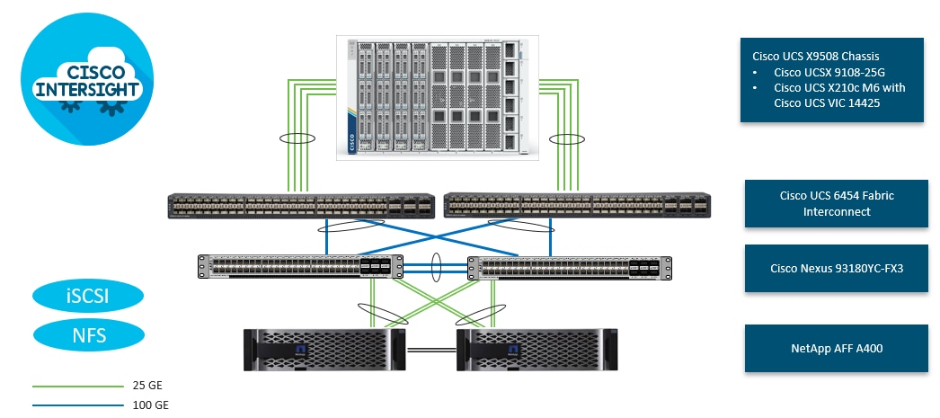
To validate the IP-based storage access in a FlexPod configuration, the components are set up as follows:
● Cisco UCS 6454 Fabric Interconnects provide the chassis and network connectivity.
● The Cisco UCS X9508 Chassis connects to fabric interconnects using Cisco UCS 9108 25G intelligent fabric modules (IFMs), where four 25 Gigabit Ethernet ports are used on each IFM to connect to the appropriate FI. If additional bandwidth is required, all eight 25G ports can be utilized.
● Cisco UCSX-210c M6 Compute Nodes contain fourth-generation Cisco 14425 virtual interface cards.
● Cisco Nexus 93180YC-FX3 Switches in Cisco NX-OS mode provide the switching fabric.
● Cisco UCS 6454 Fabric Interconnect 100-Gigabit Ethernet uplink ports connect to Cisco Nexus 93180YC-FX3 Switches in a Virtual Port Channel (vPC) configuration.
● The NetApp AFF A400 controller connects to the Cisco Nexus 93180YC-FX3 Switches using four 25 GE ports from each controller configured as a vPC.
● VMware 7.0 U3i ESXi software is installed on Cisco UCSX-210c M6 Compute Nodes to validate the infrastructure. For bare-metal scenarios SLES for SAP 15 SP4 and RHEL 8.6 for SAP are installed.
Note: With SAP HANA, iSCSI connection option is only allowed for boot disk/LUN. In this IP based storage access configuration, HANA data, log and shared filesystems leverage NFS.
FC-based Storage Access: FC and NFS
The physical topology for the FC and NFS-based FlexPod Datacenter is shown in Figure 25.
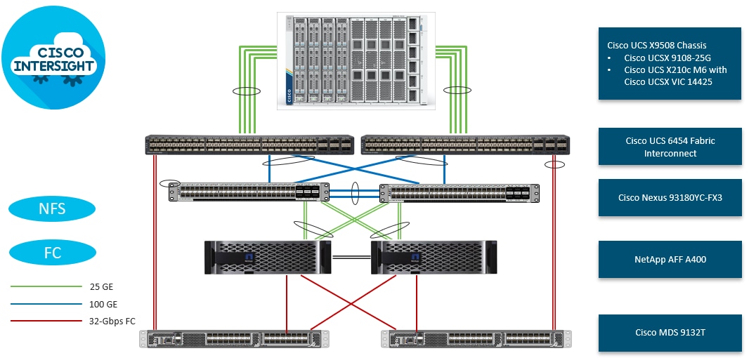
To validate the FC-based storage access in a FlexPod configuration, the components are set up as follows:
● Cisco UCS 6454 Fabric Interconnects provide the chassis and network connectivity.
● The Cisco UCS X9508 Chassis connects to fabric interconnects using Cisco UCS 9108 25G Intelligent Fabric Modules (IFMs), where four 25 Gigabit Ethernet ports are used on each IFM to connect to the appropriate FI.
● Cisco UCS X210c M6 Compute Nodes contain fourth-generation Cisco 14425 virtual interface cards.
● Cisco Nexus 93180YC-FX3 Switches in Cisco NX-OS mode provide the switching fabric.
● Cisco UCS 6454 Fabric Interconnect 100 Gigabit Ethernet uplink ports connect to Cisco Nexus 93180YC-FX3 Switches in a vPC configuration.
● The NetApp AFF A400 controller connects to the Cisco Nexus 93180YC-FX3 Switches using four 25 GE ports from each controller configured as a vPC for NFS traffic.
● Cisco UCS 6454 Fabric Interconnects are connected to the Cisco MDS 9132T switches using 32-Gbps Fibre Channel connections configured as a single port channel for SAN connectivity.
● The NetApp AFF controller connects to the Cisco MDS 9132T switches using 32-Gbps Fibre Channel connections for SAN connectivity.
● VMware 7.0 U3i ESXi software is installed on Cisco UCS X210c M6 Compute Nodes to validate the infrastructure. For bare-metal scenarios SLES for SAP 15 SP4 and RHEL 8.6 for SAP are installed.
VLAN Configuration
Table 1 lists VLANs configured for setting up the FlexPod environment along with their usage.
| VLAN ID |
Name |
Usage |
| 2 |
Native-VLAN |
Use VLAN 2 as native VLAN instead of default VLAN (1). |
| 1070 |
OOB-MGMT |
Out-of-band management VLAN to connect management ports for various devices. |
| 1071 |
IB-MGMT |
In-band management VLAN utilized for all in-band management connectivity - for example, Admin network for ESXi hosts, VM management, and so on. |
| 1072 |
vMotion *** |
VMware vMotion traffic. |
| 1073 |
HANA-Replication |
HANA system replication network |
| 1074 |
HANA-Data |
SAP HANA Data NFS filesystem network for IP/NFS only solution** |
| 1075 |
Infra-NFS *** |
NFS VLAN for mounting datastores in ESXi servers for VM boot disks** |
| 1076 |
HANA-Log |
SAP HANA Log NFS filesystem network for IP/NFS only solution** |
| 1077 |
HANA-Shared |
SAP HANA shared filesystem network** |
| 1078* |
iSCSI-A |
iSCSI-A path for storage traffic including boot-from-san traffic** |
| 1079* |
iSCSI-B |
iSCSI-B path for storage traffic including boot-from-san traffic** |
| 75 |
Infra-Backup |
Backup server network ** |
| 76 |
HANA-Appserver |
SAP Application server network |
* iSCSI VLANs are not required if using FC storage access.
** IP gateway is not needed since no routing is required for these subnets
***only needed for Virtualized SAP HANA use-cases.
Some of the key highlights of VLAN usage are as follows:
● VLAN 1070 allows you to manage and access out-of-band management interfaces of various devices.
● VLAN 1071 is used for in-band management of VMs, ESXi hosts, admin network in case of bare-metal system and other infrastructure services.
● VLAN 1072 is used for VM vMotion.
● VLANs 1073, 76 are used for SAP HANA system traffic – for example, system replication and SAP Application server network.
● VLAN 1074 and 1076 are used for SAP HANA Data and Log NFS networks – only needed in IP only solution and virtualized SAP HANA system for SAP HANA data and log filesystem mounts.
● VLAN 1075 provides ESXi SAP HANA hosts access to the NFS datastores hosted on the NetApp Controllers for deploying VMs.
● VLAN 1077 provides SAP HANA nodes access to HANA shared filesystem and additionally HANA shared persistence volumes in case of virtualized SAP HANA.
● A pair of iSCSI VLANs (1078 and 1079) is configured to provide access to boot LUNs for ESXi hosts or bare-metal SAP HANA nodes. These VLANs are not needed if you are using FC-only connectivity.
● VLAN 75 is the datacenter backup network.
VSAN Configuration
Table 2 lists the VSANs configured for setting up the FlexPod environment along with their usage.
| VSAN ID |
Name |
Usage |
| 101 |
FlexPod-Fabric-A |
VSAN ID of MDS-A switch for boot-from-SAN and SAP HANA storage access |
| 102 |
FlexPod-Fabric-B |
VSAN ID of MDS-B switch for boot-from-SAN and SAP HANA storage access |
A pair of VSAN IDs (101 and 102) are configured to provide block storage access for the ESXi or Linux hosts and the SAP HANA database’s data, log, and shared mounts .
In FlexPod Datacenter deployments, each Cisco UCS server equipped with a Cisco Virtual Interface Card (VIC) is configured for multiple virtual Network Interfaces (vNICs), which appear as standards-compliant PCIe endpoints to the OS. The end-to-end logical connectivity including VLAN/VSAN usage between the server profile for an ESXi host and the storage configuration on NetApp AFF A400 controllers is captured in the following subsections.
Logical Topology for IP-based Storage Access
Figure 26 illustrates the end-to-end connectivity design for IP-based storage access.
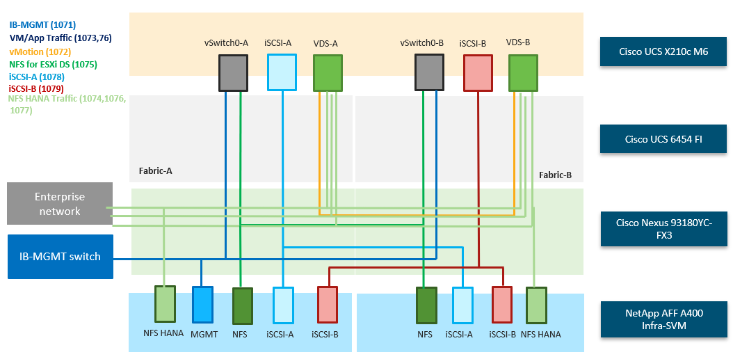
Each ESXi server profile supports:
● Managing the ESXi hosts using a common management segment.
● Diskless SAN boot using iSCSI with persistent operating system installation for true stateless computing.
● Six vNICs where:
◦ Two redundant vNICs (vSwitch0-A and vSwitch0-B) carry management and infrastructure NFS traffic. The MTU value for these vNICs is set as a Jumbo MTU (9000).
◦ Two redundant vNICs (VDS-A and VDS-B) are used by the vSphere Distributed switch and carry VMware vMotion traffic and SAP HANA networks traffic*. The MTU for the vNICs is set to Jumbo MTU (9000).
◦ One iSCSI-A vNIC used by iSCSI-A vSwitch to provide access to iSCSI-A path. The MTU value for the vNIC is set to Jumbo MTU (9000).
◦ One iSCSI-B vNIC used by iSCSI-B vSwitch to provide access to iSCSI-B path. The MTU value for this vNIC is set to Jumbo MTU (9000).
● Each ESXi host (compute node) mounts VM datastores from NetApp AFF A400 controllers for deploying virtual machines. Node VMs can also leverage direct mounted SAP HANA persistence filesystems.
Note: For bare-metal installations, apart from those for iSCSI and in-band management, create individual vNICs corresponding to the required SAP HANA networks.
Logical Topology for FC-based Storage Access
Figure 27 illustrates the end-to-end connectivity design for FC-based storage access.
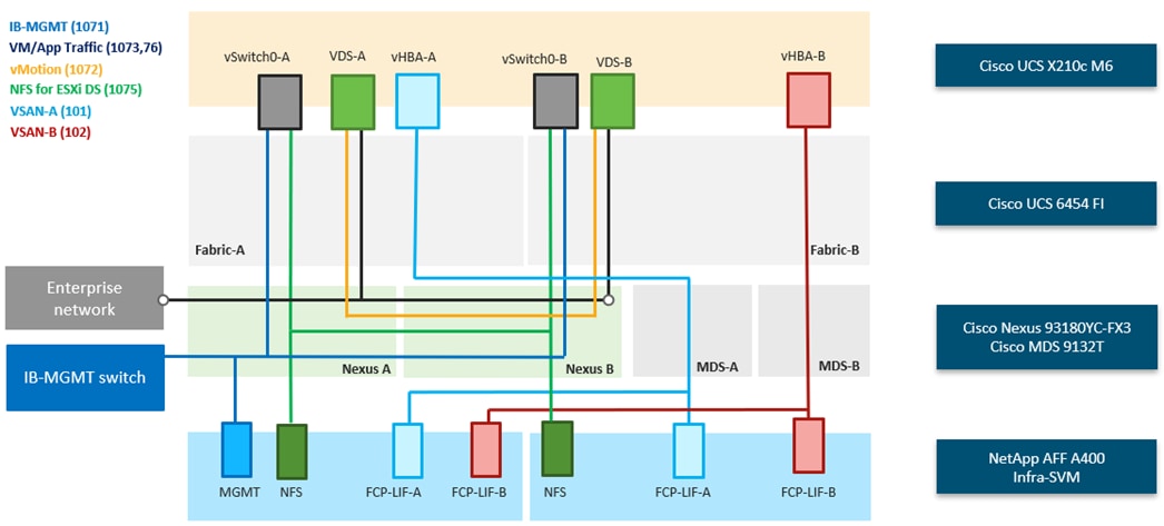
Each ESXi server profile supports:
● Managing the ESXi hosts using a common management segment.
● Diskless SAN boot using FC with persistent operating system installation for true stateless computing.
● Four vNICs where:
◦ Two redundant vNICs (vSwitch0-A and vSwitch0-B) carry in-band management, and Infrastructure NFS VLANs. The MTU value for these vNICs is set as a Jumbo MTU (9000).
◦ Two redundant vNICs (VDS-A and VDS-B) are used by the vSphere Distributed switch and carry VMware vMotion traffic and SAP HANA networks traffic*. The MTU for the vNICs is set to Jumbo MTU (9000).
◦ One vHBA defined on Fabric A to provide access to SAN-A path.
◦ One vHBA defined on Fabric B to provide access to SAN-B path.
● Each ESXi host (compute node) mounts VM datastores from NetApp AFF A400 controllers for deploying virtual machines. Node VMs can also leverage direct mounted SAP HANA persistence filesystems.
Note: For bare-metal installations, apart from in-band management, create individual vNICs corresponding to the required SAP HANA networks.
Note: *Scale-up system requiring SAP Application server connect, backup network and HANA system replication network access is assumed for the example and hence 220-222 VLANs are suggested. Optionally, additional NFS network can be defined to facilitate direct mounts of SAP HANA persistence filesystems – 1077. For more information, go to: SAP HANA TDI network requirements for more details about the networks you may want to define for your SAP HANA system.
The Cisco UCS X9508 Chassis is equipped with the Cisco UCSX 9108-25G intelligent fabric modules (IFMs). The Cisco UCS X9508 Chassis connects to each Cisco UCS 6454 FI using four 25GE ports, as shown in Figure 28. If you require more bandwidth, all eight ports on the IFMs can be connected to each FI.
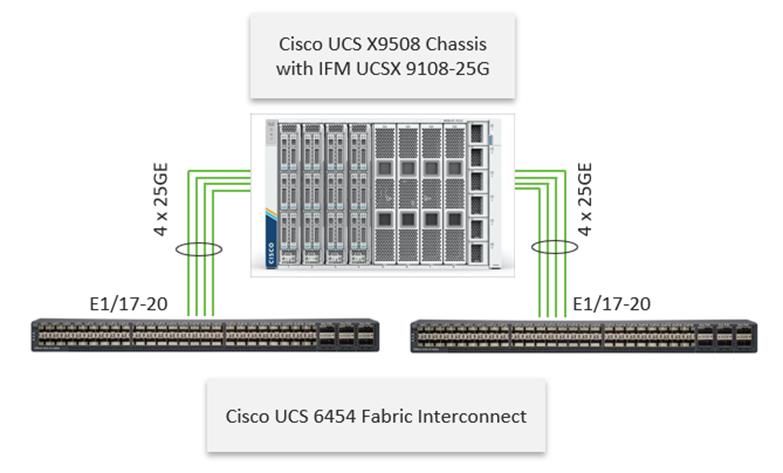
Cisco Nexus Ethernet Connectivity
The Cisco Nexus 93180YC-FX3 device configuration explains the core networking requirements for Layer 2 and Layer 3 communication. Some of the key NX-OS features implemented within the design are:
● Feature interface-vans – Allows for VLAN IP interfaces to be configured within the switch as gateways.
● Feature HSRP – Allows for Hot Standby Routing Protocol configuration for high availability.
● Feature LACP – Allows for the utilization of Link Aggregation Control Protocol (802.3ad) by the port channels configured on the switch.
● Feature VPC – Virtual Port-Channel (vPC) presents the two Nexus switches as a single “logical” port channel to the connecting upstream or downstream device.
● Feature LLDP - Link Layer Discovery Protocol (LLDP), a vendor-neutral device discovery protocol, allows the discovery of both Cisco devices and devices from other sources.
● Feature NX-API – NX-API improves the accessibility of CLI by making it available outside of the switch by using HTTP/HTTPS. This feature helps with configuring the Cisco Nexus switch remotely using the automation framework.
● Feature UDLD – Enables unidirectional link detection for various interfaces.
Cisco UCS Fabric Interconnect 6454 Ethernet Connectivity
Cisco UCS 6454 FIs are connected to Cisco Nexus 93180YC-FX3 switches using 100GE connections configured as virtual port channels. Each FI is connected to both Cisco Nexus switches using a 100G connection; additional links can easily be added to the port channel to increase the bandwidth as needed. Figure 29 illustrates the physical connectivity details.
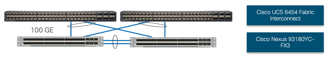
NetApp AFF A400 Ethernet Connectivity
NetApp AFF A400 controllers are connected to Cisco Nexus 93180YC-FX3 switches using 25GE connections configured as virtual port channels. The storage controllers are deployed in a switchless cluster configuration and are connected to each other using the 100GE ports e3a and e3b. Figure 30 illustrates the physical connectivity details.
In Figure 30, the two storage controllers in the high-availability pair are drawn separately for clarity. Physically, the two controllers exist within a single chassis.
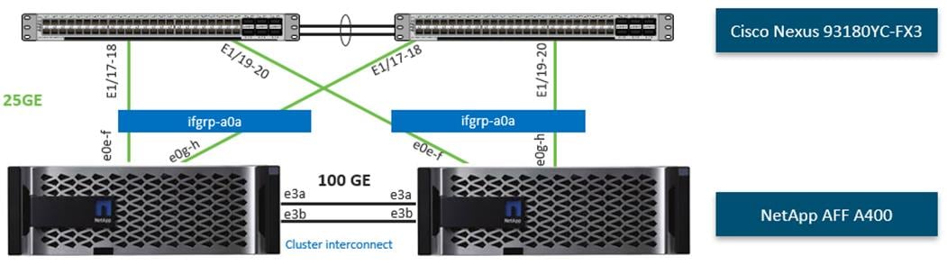
Cisco MDS SAN Connectivity – Fibre Channel Only Design
The Cisco MDS 9132T is the key design component bringing together the 32Gbps Fibre Channel (FC) capabilities to the FlexPod design. A redundant 32 Gbps Fibre Channel SAN configuration is deployed utilizing two Cisco MDS 9132Ts switches. Some of the key MDS features implemented within the design are:
● Feature NPIV – N port identifier virtualization (NPIV) provides a means to assign multiple FC IDs to a single N port.
● Feature fport-channel-trunk – F-port-channel-trunks allow for the fabric logins from the NPV switch to be virtualized over the port channel. This provides nondisruptive redundancy should individual member links fail.
● Smart-Zoning – a feature that reduces the number of TCAM entries by identifying the initiators and targets in the environment.
Cisco UCS Fabric Interconnect 6454 SAN Connectivity
For SAN connectivity, each Cisco UCS 6454 Fabric Interconnect is connected to a Cisco MDS 9132T SAN switch using 2 x 32G Fibre Channel port-channel connection, as shown in Figure 31:
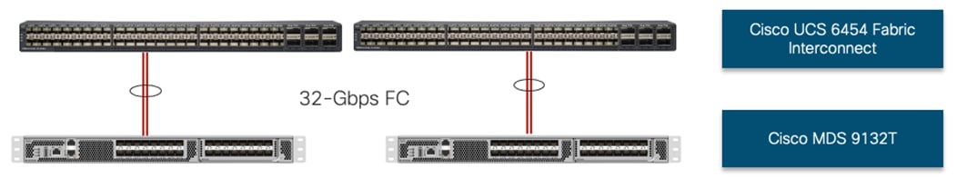
NetApp AFF A400 SAN Connectivity
For SAN connectivity, each NetApp AFF A400 controller is connected to both of Cisco MDS 9132T SAN switches using 32G Fibre Channel connections, as shown in Figure 32:
In Figure 32, the two storage controllers in the high-availability pair are drawn separately for clarity. Physically, the two controllers exist within a single chassis.
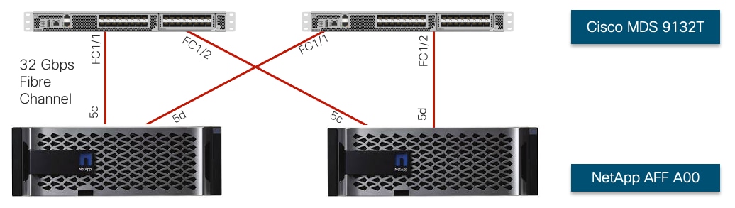
Cisco UCS X-Series Configuration - Cisco Intersight Managed Mode
Cisco Intersight Managed Mode standardizes policy and operation management for Cisco UCS X-Series. The compute nodes in Cisco UCS X-Series are configured using server profiles defined in Cisco Intersight. These server profiles derive all the server characteristics from various policies and templates. At a high level, configuring Cisco UCS using Intersight Managed Mode consists of the steps shown in Figure 33.

Set up Cisco UCS Fabric Interconnect for Cisco Intersight Managed Mode
During the initial configuration, for the management mode the configuration wizard enables you to choose whether to manage the fabric interconnect through Cisco UCS Manager or the Cisco Intersight platform. You can switch the management mode for the fabric interconnects between Cisco Intersight and Cisco UCS Manager at any time; however, Cisco UCS FIs must be set up in Intersight Managed Mode (IMM) for configuring the Cisco UCS X-Series system. Figure 34 shows the dialog during initial configuration of Cisco UCS FIs for setting up IMM.
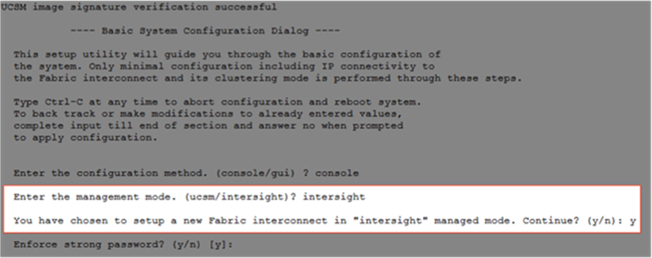
Claim a Cisco UCS Fabric Interconnect in the Cisco Intersight Platform
After setting up the Cisco UCS fabric interconnect for Cisco Intersight Managed Mode, FIs can be claimed to a new or an existing Cisco Intersight account. When a Cisco UCS fabric interconnect is successfully added to the Cisco Intersight platform, all future configuration steps are completed in the Cisco Intersight portal.
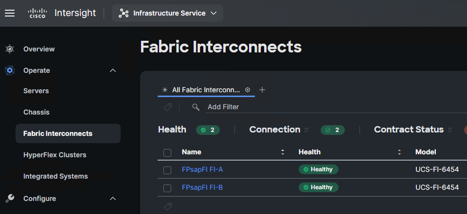
You can verify whether a Cisco UCS fabric interconnect is in Cisco UCS Manager managed mode or Cisco Intersight Managed Mode by clicking on the fabric interconnect name and looking at the detailed information screen for the FI, as shown in Figure 36.
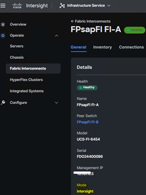
Cisco UCS Chassis Profile
A Cisco UCS Chassis profile configures and associate chassis policy to an IMM claimed chassis. The chassis profile feature is available in Intersight only if you have installed the Intersight Essentials License. The chassis-related policies can be attached to the profile either at the time of creation or later.
The chassis profile in a FlexPod is used to set the power policy for the chassis. By default, Cisco UCSX power supplies are configured in GRID mode, but the power policy can be utilized to set the power supplies in non-redundant or N+1/N+2 redundant modes.
Cisco UCS Domain Profile
A Cisco UCS domain profile configures a fabric interconnect pair through reusable policies, allows configuration of the ports and port channels, and configures the VLANs and VSANs to be used in the network. It defines the characteristics of and configures the ports on the fabric interconnects. One Cisco UCS domain profile can be assigned to one fabric interconnect domain, and the Cisco Intersight platform supports the attachment of one port policy per Cisco UCS domain profile.
Some of the characteristics of the Cisco UCS domain profile in the FlexPod environment are:
● A single domain profile is created for the pair of Cisco UCS fabric interconnects.
● Unique port policies are defined for the two fabric interconnects.
● The VLAN configuration policy is common to the fabric interconnect pair because both fabric interconnects are configured for same set of VLANs.
● The VSAN configuration policies (FC connectivity option) are unique for the two fabric interconnects because the VSANs are unique.
● The Network Time Protocol (NTP), network connectivity, and system Quality-of-Service (QoS) policies are common to the fabric interconnect pair.
After the Cisco UCS domain profile has been successfully created and deployed, the policies including the port policies are pushed to Cisco UCS fabric interconnects. Cisco UCS domain profile can easily be cloned to install additional Cisco UCS systems. When cloning the UCS domain profile, the new UCS domains utilize the existing policies for consistent deployment of additional Cisco UCS systems at scale.
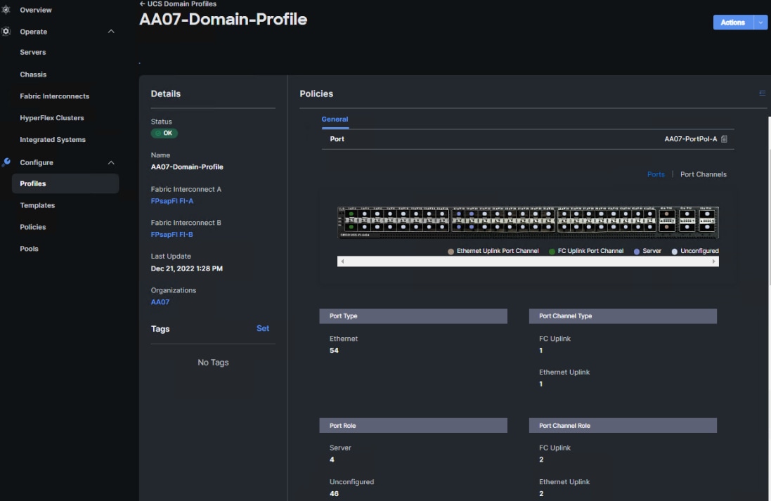
The Cisco UCS X9508 Chassis and Cisco UCS X210c M6 Compute Nodes are automatically discovered when the ports are successfully configured using the domain profile as shown in Figure 38, Figure 39, and Figure 40.
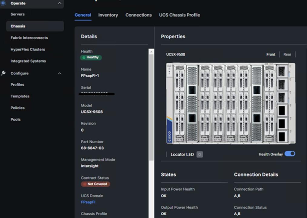
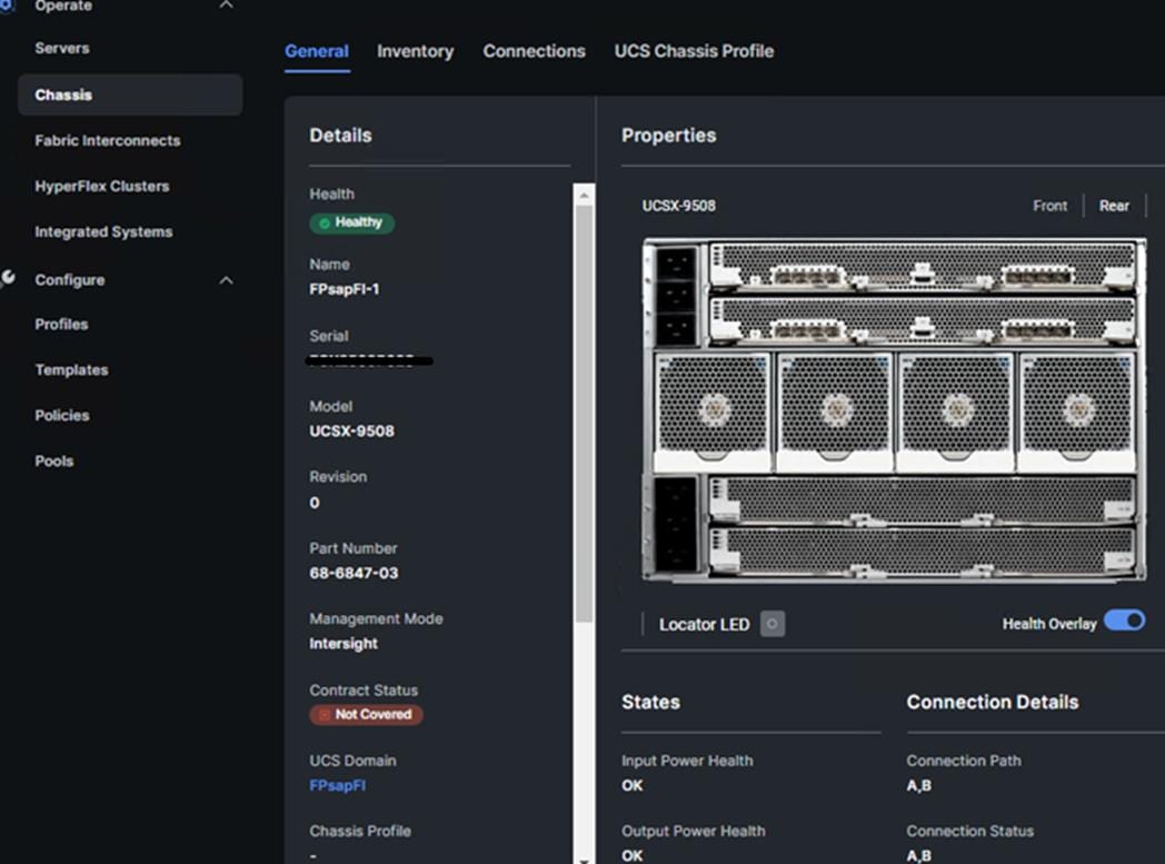
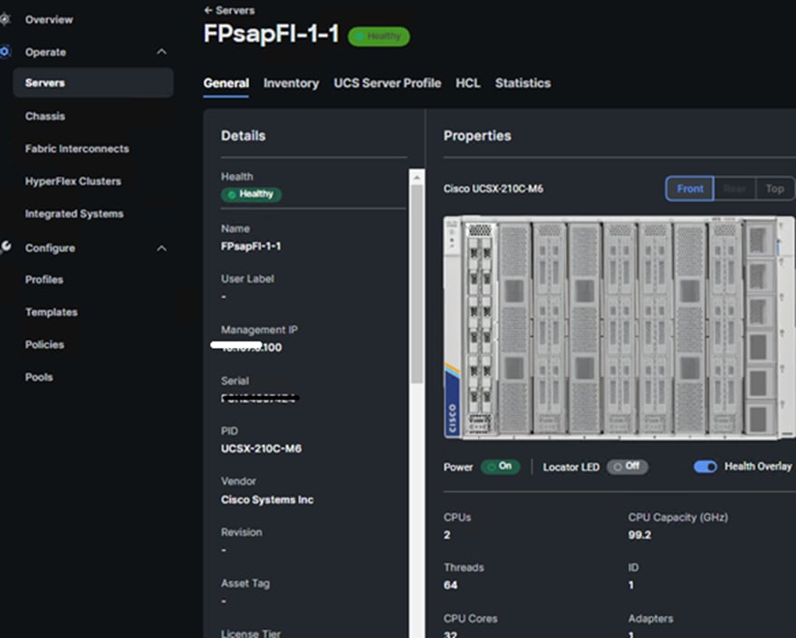
Server Profile Template
A server profile template enables resource management by simplifying policy alignment and server configuration. A server profile template is created using the server profile template wizard. The server profile template wizard groups the server policies into the following four categories to provide a quick summary view of the policies that are attached to a profile:
● Compute policies: BIOS, boot order, and virtual media policies.
● Network policies: adapter configuration, LAN connectivity, and SAN connectivity policies.
● The LAN connectivity policy requires you to create Ethernet network policy, Ethernet adapter policy, and Ethernet QoS policy.
● The SAN connectivity policy requires you to create Fibre Channel (FC) network policy, Fibre Channel adapter policy, and Fibre Channel QoS policy. SAN connectivity policy is only required for the FC connectivity option.
● Storage policies: not used in FlexPod.
● Management policies: device connector, Intelligent Platform Management Interface (IPMI) over LAN, Lightweight Directory Access Protocol (LDAP), local user, network connectivity, Simple Mail Transfer Protocol (SMTP), Simple Network Management Protocol (SNMP), Secure Shell (SSH), Serial over LAN (SOL), syslog, and virtual Keyboard, Video, and Mouse (KVM) policies.
Some characteristics of the server profile template for FlexPod are as follows:
● BIOS policy is created to specify various server parameters in accordance with FlexPod best practices.
● Boot order policy defines virtual media (KVM mapper DVD), all SAN paths for NetApp iSCSI or Fibre Channel logical interfaces (LIFs), and UEFI Shell.
● IMC access policy defines the management IP address pool for KVM access.
● Local user policy is used to enable KVM-based user access.
● For the iSCSI boot from SAN configuration, LAN connectivity policy is used to create six virtual network interface cards (vNICs) — two for management virtual switch (vSwitch0), two for application Virtual Distributed Switch (VDS), and one each for iSCSI A/B vSwitches. Various policies and pools are also created for the vNIC configuration.
● For the FC boot from SAN configuration, LAN connectivity policy is used to create four virtual network interface cards (vNICs) — two for management virtual switches (vSwitch0) and two for application Virtual Distributed Switch (VDS) — along with various policies and pools.
● For the FC connectivity option, SAN connectivity policy is used to create two virtual host bus adapters (vHBAs) — one for SAN A and one for SAN B — along with various policies and pools. The SAN connectivity policy is not required for iSCSI setup.
Figure 41 shows various policies associated with the server profile template.
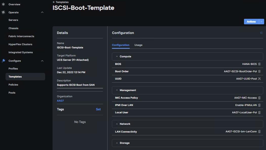
Derive and Deploy Server Profiles from the Cisco Intersight Server Profile Template
The Cisco Intersight server profile allows server configurations to be deployed directly on the compute nodes based on polices defined in the server profile template. After a server profile template has been successfully created, server profiles can be derived from the template and associated with the Cisco UCS X210c M6 Compute Nodes, as shown in Figure 42.
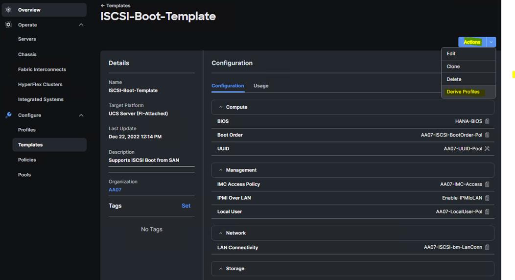
On successful deployment of the server profile, the Cisco UCS X210c M6 Compute Nodes are configured with parameters defined in the server profile and can boot from the storage LUN hosted on NetApp AFF A400.
NetApp AFF A400 – Storage Virtual Machine (SVM) Design
To provide the necessary data segregation and management, a dedicated SVM, Infra-SVM, is created for hosting the VMware environment. The SVM contains the following volumes and logical interfaces (LIFs):
● Volumes
◦ ESXi boot LUNs used to enable ESXi host boot from SAN functionality using iSCSI or FC
◦ Infrastructure datastores used by the vSphere environment to store the VMs OS and swap files
◦ SAP HANA datastores providing the persistence partitions – data, log, and shared filesystems
● Logical interfaces (LIFs)
◦ NFS LIFs to mount NFS datastores in the vSphere environment
◦ iSCSI A/B LIFs for iSCSI traffic
or
● FC LIFs for supporting FC SAN traffic
Details on volumes, VLANs, and logical interfaces (LIFs) are shown in Figure 43 and Figure 44 , for iSCSI and FC connectivity, respectively.
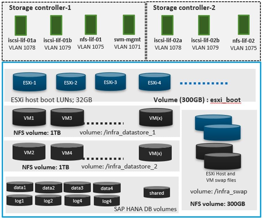
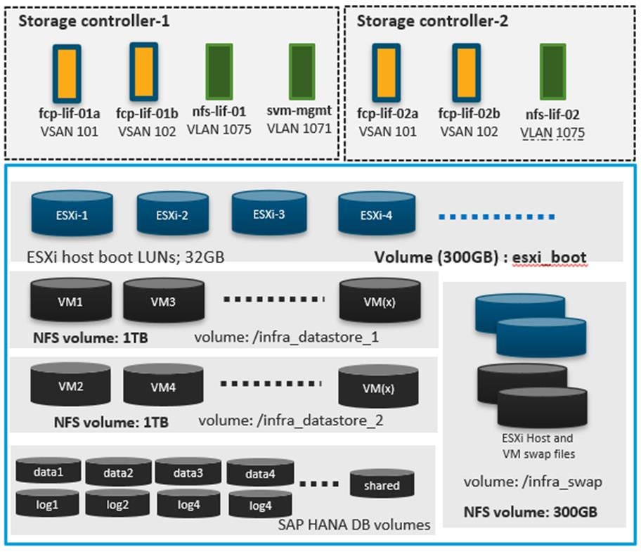
Note: For bare-metal installations, you need to configure boot LUNs for HANA nodes and HANA data and log LUNs. With Scale-up systems, the HANA shared could be carved out of a FC LUN or an NFS volume.
Multiple vNICs (and vHBAs) are created for the ESXi hosts using the Cisco Intersight server profile and are then assigned to specific virtual and distributed switches. The vNIC and (optional) vHBA distribution for the ESXi hosts is as follows:
● Two vNICs (one on each fabric) for vSwitch0 to support core services such as management and NFS traffic.
● Two vNICs (one on each fabric) for vSphere Virtual Distributed Switch (VDS) to support SAP HANA networks traffic and vMotion traffic.
● One vNIC each for Fabric-A and Fabric-B for iSCSI stateless boot. These vNICs are only required when iSCSI boot from SAN configuration is desired.
● One vHBA each for Fabric-A and Fabric-B for FC stateless boot. These vHBAs are only required when FC connectivity is desired.
Note: Typically, you will either have iSCSI vNICs or the FC vHBAs configured for stateless boot from SAN of the ESXi servers.
Figure 45 and Figure 46 show the ESXi vNIC configurations in detail.
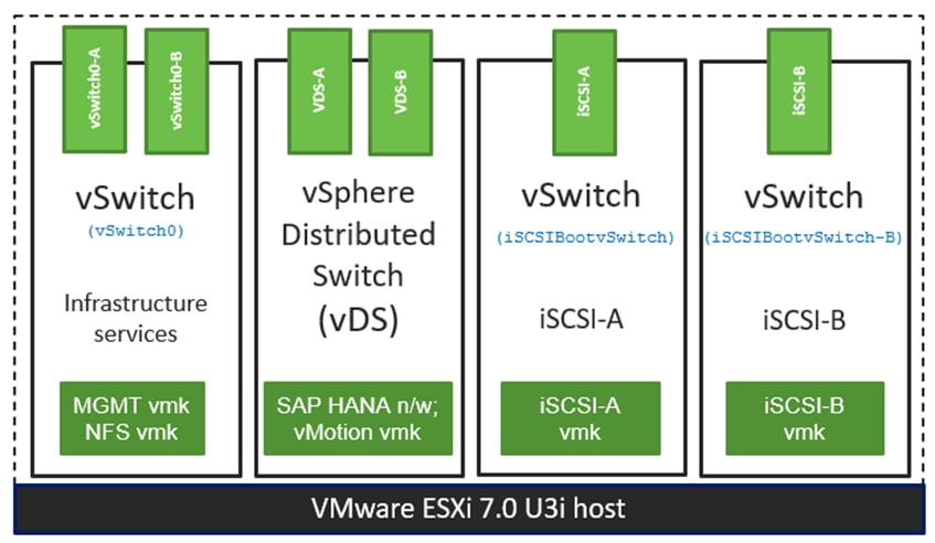
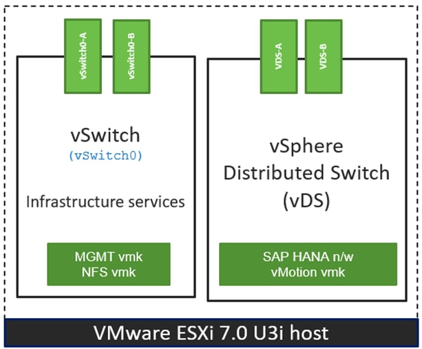
Cisco Intersight Integration with VMware vCenter and NetApp Storage
Cisco Intersight works with NetApp’s ONTAP storage and VMware vCenter using third-party device connectors. Since third-party infrastructure does not contain any built-in Intersight device connector, Cisco Intersight Assist virtual appliance enables Cisco Intersight to communicate with non-Cisco devices.
Note: A single Cisco Intersight Assist virtual appliance can support both NetApp ONTAP storage and VMware vCenter.
Cisco Intersight integration with VMware vCenter and NetApp ONTAP enables you to perform the following tasks from the Cisco Intersight dashboard:
● Monitor the virtualization and storage environment.
● Add various dashboard widgets to obtain useful at-a-glance information.
● Perform common Virtual Machine tasks such as power on/off, remote console and so on.
● Orchestrate virtual and storage environment to perform common configuration tasks.
● Orchestrate NetApp ONTAP storage tasks to setup a Storage Virtual Machine and provide NAS and SAN services.
The following sections explain the details of these operations. Since Cisco Intersight is a SaaS platform, the monitoring and orchestration capabilities are constantly being added and delivered seamlessly from the cloud.
Note: The monitoring capabilities and orchestration tasks and workflows listed below provide an in-time snapshot for your reference. For the current list of capabilities and features, you should use the help and search capabilities in Cisco Intersight.
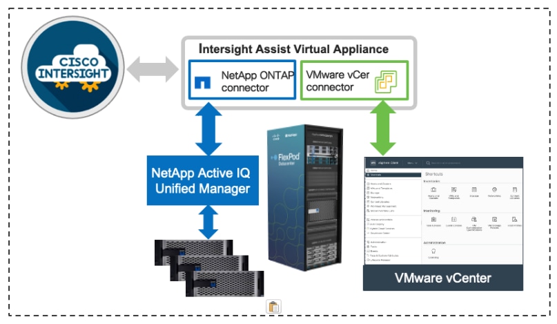
Licensing Requirement
To integrate and view various NetApp storage and VMware vCenter parameters from Cisco Intersight, a Cisco Intersight Advantage license is required. To use Cisco Intersight orchestration and workflows to provision the storage and virtual environments, an Intersight Premier license is required.
Integrate Cisco Intersight with NetApp ONTAP Storage
To integrate NetApp AFF A400 with Cisco Intersight, you need to deploy:
● Cisco Intersight Assist virtual appliance
● NetApp Active IQ Unified Manager virtual appliance
Using Cisco Intersight Assist, NetApp Active IQ Unified Manager is claimed as a target in Cisco Intersight, as shown in Figure 48.
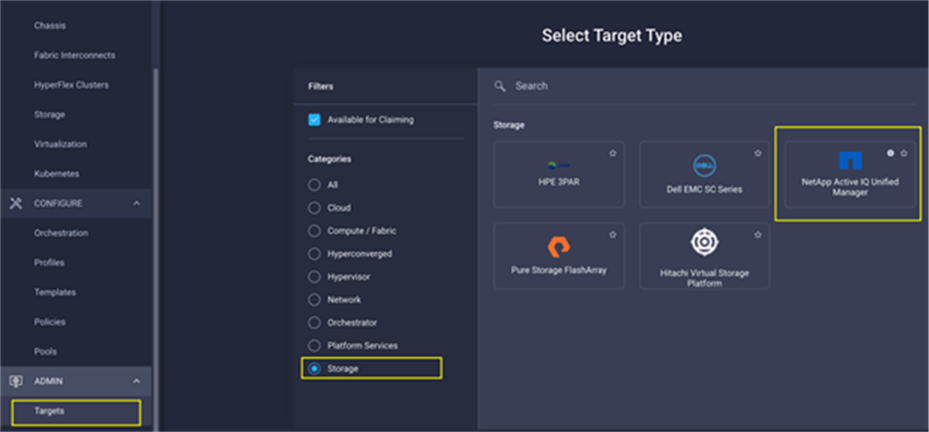
Obtain Storage-level Information
After successfully claiming the NetApp Active IQ Unified Manager as a target, you can view storage-level information in Cisco Intersight if you have already added NetApp AFF A400 to the NetApp Active IQ Unified Manager.
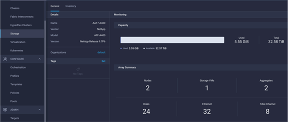
Table 3 lists some of the core NetApp AFF A400 information presented through Cisco Intersight.
Table 3. NetApp Storage Information in Cisco Intersight
| Category |
Name |
Details |
| General |
Name |
Name of the controller |
| Vendor |
NetApp |
|
| Model |
NetApp AFF model information (for example, AFF-A400) |
|
| Version |
Software version |
|
| Monitoring |
Capacity |
Total, used, and available system capacity. |
| Summary of Nodes, Storage VMs, Aggregates, disks and so on, in the system. |
||
| Inventory |
Volumes |
Volumes defined in the system and their status, size, usage, and configured export policies. |
| LUNs |
LUNs defined in the system and their status, size, usage, and mapped iGroups. |
|
| Aggregates |
Configured aggregates and their status, size, usage, and space savings. |
|
| Storage VMs |
Storage VM (SVM) information, state, allowed protocols, and logical ethernet and fibre channel interface details. |
|
| Export policies |
Export policies defined in the system and the associated SVMs. |
|
| SAN initiator groups |
SAN initiator groups, their type, protocol, initiator information, and associated SVMs. |
|
| Licenses |
Licenses installed on the system. |
|
| Nodes |
Controller information, such as model, OS, serial number, and so on. |
|
| Disks |
Disk information, including type, model, size, node information, status of the disks, and aggregate details. |
|
| Ports |
Ethernet and FC ports configured on the system. |
Storage Widget in the Dashboard
You can also add the storage dashboard widgets to Cisco Intersight for viewing NetApp AFF A400 at a glance information on the Cisco Intersight dashboard, as shown in Figure 50.
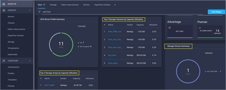
These storage widgets provide useful information, such as:
● Storage arrays and capacity utilization
● Top-five storage volumes by capacity utilization
● Storage versions summary, providing information about the software version and the number of storage systems running that version
Cisco Intersight Orchestrator – NetApp ONTAP Storage
Cisco Intersight Orchestrator provides various workflows that can be used to automate storage provisioning. Some of the sample storage workflows available for NetApp ONTAP storage are listed in Table 4.
Table 4. NetApp ONTAP Storage Workflows in Cisco Intersight Orchestrator
| Name |
Details |
| New NAS datastore |
Create a NFS storage volume and build NAS datastore on the volume. |
| New storage export policy |
Create a storage export policy and add the created policy to a NFS volume. |
| New storage host |
Create a new storage host or iGroup to enable SAN mapping. |
| New storage interface |
Create a storage IP or FC interface. |
| New storage virtual machine |
Create a storage virtual machine. |
| New VMFS datastore |
Create a storage volume and build a Virtual Machine File System (VMFS) datastore on the volume. |
| Remove NAS datastore |
Remove the NAS datastore and the underlying NFS storage volume. |
| Remove storage export policy |
Remove the NFS volume and the export policy attached to the volume. |
| Remove storage host |
Remove a storage host. If a host group name is provided as input, the workflow will also remove the host from the host group. |
| Remove VMFS datastore |
Remove a VMFS data store and remove the backing volume from the storage device. |
| Update NAS datastore |
Update NAS datastore by expanding capacity of the underlying NFS volume. |
| Update storage host |
Update the storage host details. If the inputs for a task are provided, then the task is run; otherwise, it is skipped. |
| Update VMFS datastore |
Expand a datastore on the hypervisor manager by extending the backing storage volume to specified capacity, and then expand the data store to use the additional capacity. |
In addition to these workflows, Cisco Intersight Orchestrator also provides many storage and virtualization tasks for you to create custom workflow based on their specific needs. A sample subset of these tasks is highlighted in Figure 51.
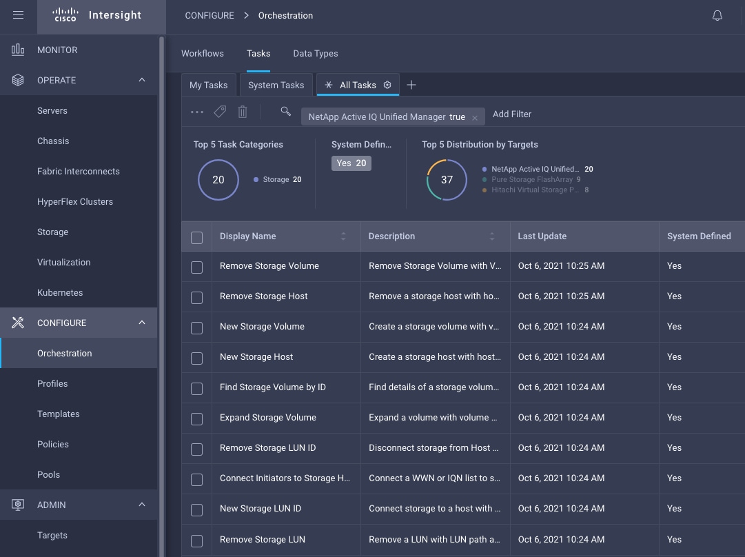
Integrate Cisco Intersight with VMware vCenter
To integrate VMware vCenter with Cisco Intersight, VMware vCenter can be claimed as a target using Cisco Intersight Assist Virtual Appliance, as shown in Figure 52.
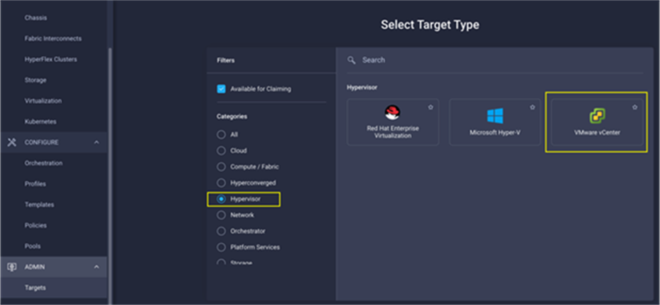
Obtain Hypervisor-level Information
After successfully claiming the VMware vCenter as a target, you can view hypervisor-level information in Cisco Intersight including hosts, VMs, clusters, datastores, and so on.
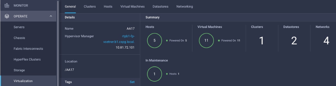
Table 5 lists some of the main virtualization properties presented in Cisco Intersight.
Table 5. Virtualization (VMware vCenter) Information in Cisco Intersight
| Category |
Name |
Details |
| General |
Name |
Name of the data center |
| Hypervisor manager |
Host name or IP address of the vCenter |
|
| Clusters |
Name |
Name of the cluster |
| Data center |
Name of the data center |
|
| Hypervisor type |
ESXi |
|
| Hypervisor manager |
vCenter IP address or the host name |
|
| CPU capacity |
CPU capacity in the cluster (GHz) |
|
| CPU consumed |
CPU cycles consumed by workloads (percentage and GHz) |
|
| Memory capacity |
Total memory in the cluster (GB) |
|
| Memory consumed |
Memory consumed by workloads (percentage and GB) |
|
| Total cores |
All the CPU cores across the CPUs in the cluster |
|
| VMware cluster information allows you to access additional details about hosts and virtual machines associated with the cluster. |
||
| Hosts |
Name |
Host name or IP address |
| Server |
Server profile associated with the ESXi host |
|
| Cluster |
Cluster information if the host is part of a cluster |
|
| Data center |
VMware data center |
|
| Hypervisor type |
ESXi |
|
| Hypervisor manager |
vCenter IP address of host name |
|
| Uptime |
Host uptime |
|
| Virtual Machines |
Number and state of VMs running on a host |
|
| CPU Information |
CPU cores, sockets, vendor, speed, capacity, consumption, and other CPU related information |
|
| Memory Information |
Memory capacity and consumption information |
|
| Hardware Information |
Compute node hardware information such as serial number, model and so on. |
|
| Host information allows you to access additional details about clusters, VMs, datastores, and networking related to the current ESXi host. |
||
| Virtual Machines |
Name |
Name of the VM |
| Guest OS |
Operating system, for example, RHEL, CentOS, and so on. |
|
| Hypervisor type |
ESXi |
|
| Host |
ESXi host information for the VM |
|
| Cluster |
VMware cluster name |
|
| Data center |
VMware data center name |
|
| IP address |
IP address(s) assigned to the VM |
|
| Hypervisor manager |
IP address of host name of the vCenter |
|
| Resource Information |
CPU, memory, disk, and network information |
|
| Guest Information |
Hostname, IP address and operating system information |
|
| VM information allows you to access additional details about clusters, hosts, datastores, networking, and virtual disks related to the current VM. |
||
| Datastores |
Name |
Name of the datastore in VMware vCenter |
| Type |
NFS or VMFS and so on. |
|
| Accessible |
Yes, if datastore is accessible; No, if datastore is inaccessible |
|
| Thin provisioning |
Yes, if thin provisioning is allowed; No, if thin provisioning is not allowed |
|
| Multiple host access |
Yes, if multiple hosts can mount the datastore; No, if the datastore only allows a single host |
|
| Storage capacity |
Space in GB or TB |
|
| Storage consumes |
Percentage and GB |
|
| Data center |
Name of VMware vCenter data center |
|
| Hypervisor manager |
vCenter hostname or IP address |
|
| Datastore Cluster |
Datastore cluster information if datastore cluster is configured |
|
| Hosts and Virtual Machines |
Number if hosts connected to a datastore and number of VM hosted on the datastore |
|
| Datastore information allows you to access additional details about hosts and VMs associated with the datastore. |
||
Interact with Virtual Machines
VMware vCenter integration with Cisco Intersight allows you to directly interact with the virtual machines (VMs) from the Cisco Intersight dashboard. In addition to obtaining in-depth information about a VM, including the operating system, CPU, memory, host name, and IP addresses assigned to the virtual machines, you can use Intersight to perform following actions on the virtual machines (Figure 54):
● Launch VM console
● Power off
● Reset
● Shutdown guest OS
● Restart guest OS
● Suspend
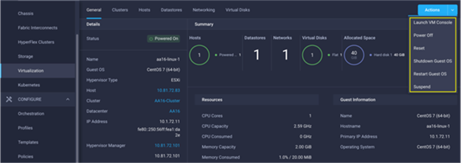
Cisco Intersight Orchestrator – VMware vCenter
Cisco Intersight Orchestrator provides various workflows that can be used for the VM and hypervisor provisioning. Some of the sample workflows available for VMware vCenter are listed in Table 6.
Table 6. VMware vCenter Workflows in Cisco Intersight Orchestrator
| Name |
Details |
| New NAS Datastore |
Create a NFS storage volume and build NAS datastore on the volume. |
| New VMFS Datastore |
Create a storage volume and build VMFS datastore on the volume. |
| New Virtual Machine |
Create a new virtual machine on the hypervisor from an OVA or OVF file. Datastore, Host/Cluster, and Image URL fields are mandatory. All other inputs are optional. |
| Remove NAS Datastore |
Remove the NAS datastore and the underlying NFS storage volume. |
| Remove VMFS Datastore |
Remove VMFS datastore and remove the backing volume from the storage device. |
| Update NAS Datastore |
Update NAS datastore by expanding capacity of the underlying NFS volume. |
| Update VMFS Datastore |
Expand a datastore on hypervisor manager by extending the backing storage volume to specified capacity, and then grow the datastore to utilize the additional capacity. |
In addition to the above workflows, Cisco Intersight Orchestrator provides many tasks for you to create custom workflows depending on their specific requirements. A sample subset of these tasks is highlighted in Figure 55.
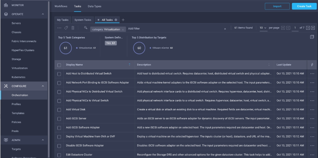
Deployment Hardware and Software
Table 7 lists the hardware and software versions used during solution validation. It is important to note that the validated FlexPod solution explained in this document adheres to Cisco, NetApp, and VMware interoperability matrix to determine support for various software and driver versions. You can use the same interoperability matrix to determine support for components that are different from the current validated design.
Click the following links for more information:
● NetApp Interoperability Matrix Tool: http://support.netapp.com/matrix/
● Cisco UCS Hardware and Software Interoperability Tool: http://www.cisco.com/web/techdoc/ucs/interoperability/matrix/matrix.html
● VMware Compatibility Guide: http://www.vmware.com/resources/compatibility/search.php
| Layer |
Device |
Image Bundle |
Comments |
| Compute |
Cisco UCS |
4.2(3d) |
Cisco UCS GA release for infrastructure including FIs and IOM/IFM. |
| Network |
Cisco Nexus 93180YC-FX3 NX-OS |
9.3(7) |
|
| Cisco MDS 9132T |
9.3(2) |
Requires SMART Licensing |
|
| Storage |
NetApp AFF A400 |
NetApp ONTAP 9.12.1P2 |
|
| Software |
Cisco UCS X210c M6 |
5.0(4b) |
Cisco UCS X-series GA release for compute nodes |
| Cisco Intersight Assist Appliance |
1.0.9-589 |
1.0.9-538 initially installed and then automatically upgraded |
|
| VMware vCenter |
7.0 Update 3l |
Build 21477706 |
|
| VMware ESXi |
7.0 Update 3i |
Build 20842708 included in Cisco Custom ISO |
|
| VMware ESXi nfnic FC Driver |
5.0.0.37 |
|
|
| VMware ESXi nenic Ethernet Driver |
1.0.45.0 |
|
|
| NetApp ONTAP Tools for VMware vSphere |
9.12 |
Formerly Virtual Storage Console (VSC) |
|
| NetApp NFS Plug-in for VMware VAAI |
2.0.1 |
|
|
| NetApp SnapCenter for vSphere |
4.9 |
Includes the vSphere plug-in for SnapCenter |
|
| NetApp Active IQ Unified Manager |
9.12 |
|
This chapter provides a high-level overview of the FlexPod design validation. Solution validation explains various aspects of the converged infrastructure including compute, virtualization, network, and storage. The test scenarios are divided into the following broad categories:
● Functional validation – physical and logical setup validation.
● Feature verification – feature verification withing FlexPod design.
● Availability testing – link and device redundancy and high availability testing. Failure and recovery of storage access paths across AFF nodes, MDS and Nexus switches, and fabric interconnects.
● SAP HANA installation and validation – verify key performance indicator (KPI) metrics with the SAP HANA hardware and cloud measurement tool (HCMT).
● Infrastructure as a code validation – verify automation and orchestration of solution components.
The goal of solution validation is to test functional aspects of the design as well as that KPI metrics per SAP prescribed HCMT tests are met. Some of the examples of the types of tests executed include:
● Verification of features configured on various FlexPod components.
● Powering off and rebooting redundant devices and removing redundant links to verify high availability.
● Failure and recovery of vCenter and ESXi hosts in a cluster.
● Failure and recovery of storage access paths across NetApp controllers, MDS and Nexus switches, and fabric interconnects.
● Server Profile migration between compute nodes.
● HCMT tests for SAP HANA scale-up system both in the bare-metal as well as virtualized configurations.
As part of the validation effort, the solution validation team identifies the problems, works with the appropriate development teams to fix the problem, and provides work arounds, as necessary.
The FlexPod Datacenter solution is a validated approach for deploying Cisco and NetApp technologies and products for building shared private and public cloud infrastructure. The best-in-class storage, server and networking components serve as the foundation for a variety of workloads not limited to SAP HANA TDI. With the introduction of Cisco X-Series modular platform to FlexPod Datacenter, you can now manage and orchestrate the next-generation Cisco UCS platform from the cloud using Cisco Intersight. Some of the key advantages of integrating Cisco UCS X-Series and Cisco Intersight into the FlexPod infrastructure are:
● A single platform built from unified compute, fabric, and storage technologies, allowing you to scale to support variety of bare-metal or virtualized enterprise workloads like SAP HANA without architectural changes.
● Simpler and programmable infrastructure.
● Centralized, simplified management of all infrastructure resources, including the NetApp AFF array and VMware vCenter by Cisco Intersight.
● Power and cooling innovations with Cisco UCS X-Series and better airflow.
● Fabric innovations for heterogeneous compute and memory composability.
● Innovative cloud operations providing continuous feature delivery.
● Future-ready design built for investment protection.
● Smart Zoning reduces the need to implement and maintain large zone databases and eases management and implementation tasks.
● Organizations can interact with a single vendor when troubleshooting problems across computing, storage, and networking environments.
In addition to the Cisco UCS X-Series hardware and software innovations, integration of the Cisco Intersight cloud platform with VMware vCenter and NetApp Active IQ Unified Manager delivers monitoring, orchestration, and workload optimization capabilities for the different layers (including virtualization and storage) of the FlexPod infrastructure. The modular nature of the Cisco Intersight platform also provides an easy upgrade path to additional services, such as workload optimization and Kubernetes.
This appendix includes links to various product pages.
● Cisco Intersight: https://www.intersight.com
● Cisco Intersight Managed Mode: https://www.cisco.com/c/en/us/td/docs/unified_computing/Intersight/b_Intersight_Managed_Mode_Configuration_Guide.html
● Cisco UCS X-Series Modular System: https://www.cisco.com/site/us/en/products/computing/servers-unified-computing-systems/ucs-x-series-modular-systems/index.html
● Cisco Unified Computing System: http://www.cisco.com/en/US/products/ps10265/index.html
● Cisco UCS 6400 Series Fabric Interconnects: https://www.cisco.com/c/en/us/products/collateral/servers-unified-computing/datasheet-c78-741116.html
● Cisco Nexus 9000 Series Switches: http://www.cisco.com/c/en/us/products/switches/nexus-9000-series-switches/index.html
● Cisco MDS 9132T Switches: https://www.cisco.com/c/en/us/products/collateral/storage-networking/mds-9100-series-multilayer-fabric-switches/datasheet-c78-739613.html
● NetApp ONTAP: https://docs.netapp.com/ontap-9/index.jsp
● NetApp Active IQ Unified Manager: https://docs.netapp.com/ocum-98/index.jsp?topic=%2Fcom.netapp.doc.onc-um-isg-lin%2FGUID-FA7D1835-F32A-4A84-BD5A-993F7EE6BBAE.html
● ONTAP Storage Connector for Cisco Intersight: https://www.netapp.com/pdf.html?item=/media/25001-tr-4883.pdf
● NetApp SAP solutions: https://docs.netapp.com/us-en/netapp-solutions-sap/index.html
● VMware vCenter Server: http://www.vmware.com/products/vcenter-server/overview.html
● VMware vSphere: https://www.vmware.com/products/vsphere
● SAP HANA on VMware vSphere Best Practices and Reference Architecture Guide: https://core.vmware.com/resource/sap-hana-vmware-vsphere-best-practices-and-reference-architecture-guide#abstract
● SAP HANA on VMware vSphere: https://wiki.scn.sap.com/wiki/plugins/servlet/mobile?contentId=449288968#content/view/449288968
SAP
Note: Requires an SAP Universal Login.
● SAP Note 2161991 – VMware vSphere configuration guidelines: https://launchpad.support.sap.com/#/notes/2161991
● SAP Note 2235581 – SAP HANA: Supported Operating Systems: https://launchpad.support.sap.com/#/notes/2235581
● SAP Note 2937606 – SAP HANA on VMware vSphere 7.0 in production: https://launchpad.support.sap.com/#/notes/2937606
Interoperability Matrix
● Cisco UCS Hardware Compatibility Matrix: https://ucshcltool.cloudapps.cisco.com/public/
● Interoperability Matrix for Cisco Nexus and MDS 9000 products: https://www.cisco.com/c/en/us/td/docs/switches/datacenter/mds9000/interoperability/matrix/intmatrx.html
● VMware and Cisco Unified Computing System: : https://www.vmware.com/resources/compatibility/search.php?deviceCategory=server&details=1&partner=146&releases=578&cpuSeries=128,147,129,146,130,148&page=1&display_interval=10&sortColumn=Partner&sortOrder=Asc
● NetApp Interoperability Matrix Tool: http://support.netapp.com/matrix/
● SAP HANA supported server and storage systems: https://www.sap.com/dmc/exp/2014-09-02-hana-hardware/enEN/#/solutions?filters=ve:1;ve:13
Pramod Ramamurthy, Technical Marketing Engineer, Cloud and Compute Group, Cisco Systems GmbH.
Pramod has over nine years of experience at Cisco with data center technologies and enterprise solution architectures. He has over 10 years of SAP Basis experience from previous roles helping customers with their SAP landscapes design, build, management, and support. As a Technical Marketing Engineer with Computing Systems Product Group’s UCS and SAP solutions team, Pramod focuses on Converged Infrastructure Solutions design, validation and associated collaterals build for SAP HANA.
Marco Schoen, Technical Marketing Engineer, NetApp, Inc.
Marco is a Technical Marketing Engineer with NetApp and has over 20 years of experience in the IT industry focusing on SAP technologies. His specialization areas include SAP NetWeaver Basis technology and SAP HANA. He is currently focusing on the SAP HANA infrastructure design, validation and certification on NetApp Storage solutions and products including various server technologies.
Acknowledgements
For their support and contribution to the design, validation, and creation of this Cisco Validated Design, the authors would like to thank:
● John George, Technical Marketing Engineer, Cisco Systems, Inc.
● Haseeb Niazi, Principal Technical Marketing Engineer, Cisco Systems, Inc.
● Joerg Wolters, Technical Marketing Engineer, Cisco Systems, Inc.
For comments and suggestions about this guide and related guides, join the discussion on Cisco Community at https://cs.co/en-cvds.
CVD Program
ALL DESIGNS, SPECIFICATIONS, STATEMENTS, INFORMATION, AND RECOMMENDATIONS (COLLECTIVELY, "DESIGNS") IN THIS MANUAL ARE PRESENTED "AS IS," WITH ALL FAULTS. CISCO AND ITS SUPPLIERS DISCLAIM ALL WARRANTIES, INCLUDING, WITHOUT LIMITATION, THE WARRANTY OF MERCHANTABILITY, FITNESS FOR A PARTICULAR PURPOSE AND NONINFRINGEMENT OR ARISING FROM A COURSE OF DEALING, USAGE, OR TRADE PRACTICE. IN NO EVENT SHALL CISCO OR ITS SUPPLIERS BE LIABLE FOR ANY INDIRECT, SPECIAL, CONSEQUENTIAL, OR INCIDENTAL DAMAGES, INCLUDING, WITHOUT LIMITATION, LOST PROFITS OR LOSS OR DAMAGE TO DATA ARISING OUT OF THE USE OR INABILITY TO USE THE DESIGNS, EVEN IF CISCO OR ITS SUPPLIERS HAVE BEEN ADVISED OF THE POSSIBILITY OF SUCH DAMAGES.
THE DESIGNS ARE SUBJECT TO CHANGE WITHOUT NOTICE. USERS ARE SOLELY RESPONSIBLE FOR THEIR APPLICATION OF THE DESIGNS. THE DESIGNS DO NOT CONSTITUTE THE TECHNICAL OR OTHER PROFESSIONAL ADVICE OF CISCO, ITS SUPPLIERS OR PARTNERS. USERS SHOULD CONSULT THEIR OWN TECHNICAL ADVISORS BEFORE IMPLE-MENTING THE DESIGNS. RESULTS MAY VARY DEPENDING ON FACTORS NOT TESTED BY CISCO.
CCDE, CCENT, Cisco Eos, Cisco Lumin, Cisco Nexus, Cisco StadiumVision, Cisco TelePresence, Cisco WebEx, the Cisco logo, DCE, and Welcome to the Human Network are trademarks; Changing the Way We Work, Live, Play, and Learn and Cisco Store are service marks; and Access Registrar, Aironet, AsyncOS, Bringing the Meeting To You, Catalyst, CCDA, CCDP, CCIE, CCIP, CCNA, CCNP, CCSP, CCVP, Cisco, the Cisco Certified Internetwork Expert logo, Cisco IOS, Cisco Press, Cisco Systems, Cisco Systems Capital, the Cisco Systems logo, Cisco Unified Computing System (Cisco UCS), Cisco UCS B-Series Blade Servers, Cisco UCS C-Series Rack Servers, Cisco UCS S-Series Storage Servers, Cisco UCS Manager, Cisco UCS Management Software, Cisco Unified Fabric, Cisco Application Centric Infrastructure, Cisco Nexus 9000 Series, Cisco Nexus 7000 Series. Cisco Prime Data Center Network Manager, Cisco NX-OS Software, Cisco MDS Series, Cisco Unity, Collaboration Without Limitation, EtherFast, EtherSwitch, Event Center, Fast Step, Follow Me Browsing, FormShare, GigaDrive, HomeLink, Internet Quotient, IOS, iPhone, iQuick Study, LightStream, Linksys, MediaTone, MeetingPlace, MeetingPlace Chime Sound, MGX, Networkers, Networking Academy, Network Registrar, PCNow, PIX, PowerPanels, ProConnect, ScriptShare, SenderBase, SMARTnet, Spectrum Expert, StackWise, The Fastest Way to Increase Your Internet Quotient, TransPath, WebEx, and the WebEx logo are registered trade-marks of Cisco Systems, Inc. and/or its affiliates in the United States and certain other countries. (LDW_P3)
All other trademarks mentioned in this document or website are the property of their respective owners. The use of the word partner does not imply a partnership relationship between Cisco and any other company. (0809R)