FlexPod Datacenter with SUSE Rancher for AI Workloads Design Guide
Available Languages
Bias-Free Language
The documentation set for this product strives to use bias-free language. For the purposes of this documentation set, bias-free is defined as language that does not imply discrimination based on age, disability, gender, racial identity, ethnic identity, sexual orientation, socioeconomic status, and intersectionality. Exceptions may be present in the documentation due to language that is hardcoded in the user interfaces of the product software, language used based on RFP documentation, or language that is used by a referenced third-party product. Learn more about how Cisco is using Inclusive Language.
- US/Canada 800-553-2447
- Worldwide Support Phone Numbers
- All Tools
 Feedback
 Feedback
Published Date: December 2023
![]()
In partnership with:


About the Cisco Validated Design Program
The Cisco Validated Design (CVD) program consists of systems and solutions designed, tested, and documented to facilitate faster, more reliable, and more predictable customer deployments. For more information, go to: http://www.cisco.com/go/designzone.
The FlexPod Datacenter solution is a validated approach for deploying Cisco and NetApp technologies and products to build shared private and public cloud infrastructure. Cisco and NetApp have partnered to deliver a series of FlexPod solutions that enable strategic data center platforms. The success of the FlexPod solution is driven by its ability to evolve and incorporate both technology and product innovations in the areas of management, computing, storage, and networking. To help organizations with their digital transformation, application modernization, and artificial intelligence and machine learning (AI/ML) practices, Cisco and NetApp have partnered to produce this Cisco Validated Design (CVD) for the FlexPod Datacenter for SUSE Rancher solution. As the hybrid-cloud operation is the new de-facto default for many companies, the network connection to the public cloud, the Kubernetes cluster management, and the workload management across on-premises and public clouds are covered as part of this solution design.
FlexPod delivers an integrated architecture that incorporates compute, storage, and network design best practices, thereby minimizing IT risks by validating the integrated architecture to ensure compatibility between various components. The solution also addresses IT pain points by providing documented design guidance, deployment guidance, and support that can be used in various stages (planning, designing, and implementation) of a deployment. FlexPod delivered as IaC further eliminates error-prone manual tasks, allowing quicker and more consistent solution deployments.
SUSE Rancher Enterprise Container Management (ECM) is an enterprise-ready Kubernetes container platform with full-stack automated operations to deploy, import and manage across edge, on-premises, hybrid cloud, and multi-cloud deployments. SUSE Rancher ECM is optimized to improve developer productivity and promote innovation. SUSE Rancher gives developers a self-service platform on which to build and run containerized applications. With SUSE Rancher ECM, you can quickly start creating new cloud-native applications or cloud-enabling existing applications and spawning an environment for a new microservice in minutes.
Combining SUSE Rancher ECM with the FlexPod solution can simplify the deployment and management of the container infrastructure. The Ansible integration with the FlexPod solution automates the deployment of the FlexPod infrastructure along with SUSE Rancher installation, enabling customers to take advantage of programming and automating the infrastructure at scale with agility, extending the benefits of automation to the entire stack.
Some of the key advantages of integrating FlexPod Datacenter with SUSE Rancher ECM are:
· Simpler and programmable infrastructure: FlexPod infrastructure delivered as infrastructure-as-code through a single partner integrable open API.
· Latest hardware and software compute innovations: policy-based configurations, delivered using Cisco Intersight, to deploy and manage the latest processor, memory, network, and power/cooling improvements.
· Storage Modernization: deliver high-speed, consistent, low latency, multi-tenant storage using a range of NetApp all-flash arrays.
· Innovative cloud operations: continuous feature delivery and no need for maintaining on-premises physical or virtual machines supporting management functions.
· Built for investment protections: design ready for future technologies such as liquid cooling and high-Wattage CPUs; CXL-ready.
The FlexPod solution includes integration of the Cisco Intersight with NetApp Active IQ Unified Manager and, if required, VMware vCenter to deliver monitoring, orchestration, and workload optimization capabilities for different layers (virtualization and storage) of the FlexPod infrastructure. The modular nature of the Cisco Intersight platform also provides an easy upgrade path to additional services, such as Intersight Workload Optimization and Intersight Cloud Orchestrator.
If you’re interested in understanding the FlexPod design and deployment details, including the configuration of various elements of design and associated best practices, see the Cisco Validated Designs for FlexPod, here: https://www.cisco.com/c/en/us/solutions/design-zone/data-center-design-guides/flexpod-design-guides.html.
Solution Overview – FlexPod Datacenter with SUSE Rancher Enterprise Container Management
This chapter contains the following:
· Audience
The featured FlexPod Datacenter for SUSE Rancher Enterprise Container Management platform solution is a pre-designed, integrated, and validated architecture for the data center that combines Cisco UCS servers, the Cisco Nexus/MDS family of switches, and NetApp AFF storage into a single, flexible architecture. FlexPod is designed for high availability (HA), with no single point of failure, while maintaining cost-effectiveness and flexibility in the design to support a wide variety of workloads. The SUSE Rancher ECM software enables and simplifies multi-cluster Kubernetes management everywhere, supporting any certified Kubernetes distribution, unifies security, policy, and user management, plus drives adoption with shared tools and services. The FlexPod solution with SUSE Rancher ECM was tested, validated with different options, and captured in the related CVD deployment guides and white papers. A list of deployment documents is available in a later section of this design document.
Integration between the Rancher ECM Platform and the storage and data management services occurs at several levels, all captured in this document. The main storage integration is based on Container Storage Interface (CSI) Astra Trident for Kubernetes Driver for NetApp storage systems, which enables container orchestrators such as Kubernetes to manage the life cycle of persistent storage.
The main focus of the FlexPod Datacenter with SUSE Rancher Enterprise Container Management solution is on a bare metal cluster with the nodes running SUSE Linux Enterprise (SLE) Micro on Cisco UCS servers. To better support smaller deployments and Test/Dev installations, the deployment of virtualized RKE2 cluster and single node deployments is also validated.
The following design and deployment aspects of the FlexPod with SUSE Rancher ECM solution are explained in this document:
· FlexPod converged infrastructure
· SUSE Rancher ECM
° SUSE Rancher Kubernetes Engine Government (RKE2)
° SUSE Linux Enterprise Micro 5.x
· NetApp Astra Trident Container Storage Interface
· NetApp Astra Control Center
This document also explains key design aspects based on the validated environment and best practices.
The intended audience of this document includes but is not limited to IT architects, sales engineers, field consultants, professional services, IT managers, partner engineering, and customers who want to take advantage of an infrastructure built to deliver IT efficiency and enable IT innovation.
This document provides design guidance around incorporating the Cisco Intersight—managed Cisco UCS platform within FlexPod Datacenter infrastructure to run SUSE Rancher Enterprise Container Management (ECM) and AI/ML workloads. The document introduces various design elements and explains various considerations and best practices for a successful deployment. This document also highlights the design and product requirements for integrating virtualization and storage systems to Cisco Intersight to deliver a true cloud-based integrated approach to infrastructure management.
These components are integrated and validated, and – where possible - the entire stack is automated so that customers can deploy the solution quickly and economically while eliminating many of the risks associated with researching, designing, building, and deploying similar solutions from the ground up.
The FlexPod Datacenter for SUSE Rancher Enterprise Container Management solution offers the following key customer benefits:
· Integrated solution that supports the entire SUSE software-defined Linux and Kubernetes stack for containerized and AI/ML workloads
· Standardized architecture for quick, repeatable, error-free deployments of FlexPod-based workload domains
· Automated life cycle management to keep all the system components up to date
· Simplified cloud-based management of various FlexPod components
· Hybrid-cloud-ready, policy-driven modular design
· Highly available, flexible, and scalable FlexPod architecture
· Cooperative support model and Cisco Solution Support
· Easy to deploy, consume, and manage design that aligns with Cisco, NetApp, and SUSE best practices and compatibility requirements
· Support for component monitoring, solution automation and orchestration, and workload optimization
Figure 1. FlexPod Datacenter for SUSE Rancher Enterprise Container Management Solution Stack
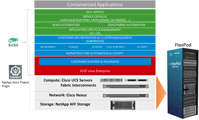
Similar to other FlexPod solution designs, FlexPod Datacenter for SUSE Rancher Enterprise Container Management is configurable according to demand and usage. You can purchase exactly the infrastructure you need for your current application requirements. You can scale up by adding more resources to the FlexPod system or scale out by adding more FlexPod instances. The FlexPod solution can also be deployed as a multi-site solution (stretched cluster or metro cluster) to address extended high-availability options and connected to the public cloud using NetApp Cloud Storage options for simplified data management across multiple locations.
This chapter contains the following:
· Cisco Unified Computing System
· Cisco Unified Computing System X-Series
· Cisco UCS C-Series Rack Servers
· Cisco UCS Scalability in FlexPod
· Cisco Nexus Switching Fabric
· Cisco MDS 9132T 32G Multilayer Fabric Switch
· SUSE Rancher Enterprise Container Management
· Infrastructure as Code with Ansible
FlexPod Datacenter architecture is built using the following infrastructure components for compute, network, and storage:
· Cisco Unified Computing System (Cisco UCS)
· Cisco Nexus and Cisco MDS switches
· NetApp All Flash FAS (AFF) storage systems
Figure 2. FlexPod Datacenter Components
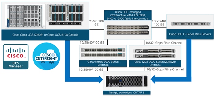
These components are connected and configured according to the best practices of both Cisco and NetApp to provide an ideal platform for running a variety of enterprise workloads with confidence. FlexPod can scale up for greater performance and capacity (adding compute, network, or storage resources individually as needed), or it can scale out for environments that require multiple consistent deployments (such as rolling out of additional FlexPod stacks).
One of the key benefits of FlexPod is its ability to maintain consistency during scale. Each of the component families shown (Cisco UCS, Cisco Nexus, Cisco MDS, and NetApp AFF) offers platform and resource options to scale the infrastructure up or down while supporting the same features and functionality that are required under the configuration and connectivity best practices of FlexPod. The key features and highlights of the FlexPod components are explained below.
Cisco Unified Computing System
Cisco Unified Computing System (Cisco UCS) is an integrated computing infrastructure with intent-based management to automate and accelerate deployment of all your applications, including virtualization and cloud computing, scale-out and bare-metal workloads, and in-memory analytics, as well as edge computing that supports remote and branch locations and massive amounts of data from the Internet of Things (IoT). The system is an integrated, scalable, multi-chassis platform in which all resources participate in a unified management domain.
While Cisco UCS is a stateless, programmable infrastructure, the Cisco UCS unified API is how management tools program it. This enables the tools to help guarantee consistent, error-free, policy-based alignment of server personalities with workloads. Through automation, transforming the server and networking components of your infrastructure into a complete solution is fast and error-free because programmability eliminates the error-prone manual configuration of servers and integration into solutions. Server, network, and storage administrators are now free to focus on strategic initiatives rather than spending their time performing tedious tasks.
With Cisco Unified Computing System, Cisco introduced the Cisco UCS Manager to manage the system. Over the last few years, the way companies run and operate their data center and operate it has changed and so has the management option for Cisco UCS. The next-generation Cisco UCS management is called Cisco Intersight and is available in an as-a-Service model.
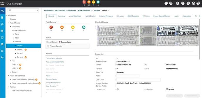
Cisco UCS Manager (UCSM) provides a unified, integrated management for all software and hardware components in Cisco UCS and manages a single domain through an intuitive HTML 5-based GUI. The Cisco UCS Manager software is embedded in each fabric interconnect. Running in a redundant, high-availability configuration, it creates a single, self-aware, self-integrating unified system that recognizes and integrates components as they are added to the system. It quickly and accurately configures computing, network, storage, and storage-access resources to reduce the chance of errors that can cause downtime. Its role and policy-based approach help organizations more easily align policies and configurations with workloads. While Cisco UCS Manager requires an “always on” connection, our other tools are evolving to manage systems to which they are not continuously connected.
For more information about the Cisco UCS Manager, see https://www.cisco.com/c/en/us/products/collateral/servers-unified-computing/ucs-b-series-blade-servers/data_sheet_c78-520522.html.
Figure 3. Cisco UCS System Manager – Server Overview
The Cisco Intersight platform is a Software-as-a-Service (SaaS) infrastructure lifecycle management platform that delivers simplified configuration, deployment, maintenance, and support. The Cisco Intersight platform is designed to be modular, so you can adopt services based on their individual requirements. The platform significantly simplifies IT operations by bridging applications with infrastructure, providing visibility and management from bare-metal servers and hypervisors to serverless applications, thereby reducing costs and mitigating risk. This unified SaaS platform uses an Open API design that natively integrates with third-party platforms and tools.
Figure 4. Cisco Intersight Overview
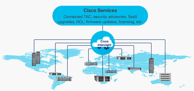
The main benefits of the Cisco Intersight infrastructure services are as follows:
· Simplify daily operations by automating many daily manual tasks
· Combine the convenience of a SaaS platform with the capability to connect from anywhere and manage infrastructure through a browser or mobile app
· Stay ahead of problems and accelerate trouble resolution through advanced support capabilities
· Gain global visibility of infrastructure health and status along with advanced management and support capabilities
· Upgrade to add workload optimization and Kubernetes services when needed
Cisco Intersight Virtual Appliance and Private Virtual Appliance
In addition to the SaaS deployment model running on Intersight.com, on-premises options can be purchased separately. The Cisco Intersight Virtual Appliance and Cisco Intersight Private Virtual Appliance are available for organizations that have additional data locality or security requirements for managing systems. The Cisco Intersight Virtual Appliance delivers the management features of the Cisco Intersight platform in an easy-to-deploy VMware Open Virtualization Appliance (OVA) or Microsoft Hyper-V Server virtual machine that allows customers to control the system details that leave their premises. The Cisco Intersight Private Virtual Appliance is provided in a form factor specifically designed for users who operate in disconnected (air gap) environments. The Private Virtual Appliance requires no connection to public networks or back to Cisco to operate.
Cisco Intersight Assist helps you add endpoint devices to Cisco Intersight. A data center could have multiple devices that do not connect directly with Cisco Intersight. Any device that is supported by Cisco Intersight, but does not connect directly with it, will need a connection mechanism. Cisco Intersight Assist provides that connection mechanism. In FlexPod, VMware vCenter and NetApp Active IQ Unified Manager, Cisco Nexus and Cisco MDS switches connect to Intersight with the help of Intersight Assist VM.
Cisco Intersight Assist is available within the Cisco Intersight Virtual Appliance, which is distributed as a deployable virtual machine contained within an Open Virtual Appliance (OVA) file format. More information about the Cisco Intersight Assist VM deployment are explained in later sections.
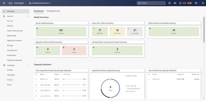
The Cisco Intersight platform uses a subscription-based license with multiple tiers. You can purchase a subscription duration of one, three, or five years and choose the required Cisco UCS server volume tier for the selected subscription duration. Each Cisco endpoint automatically includes a Cisco Intersight Base license at no additional cost when customers access the Cisco Intersight portal and claim a device. You can purchase any of the following higher-tier Cisco Intersight licenses using the Cisco ordering tool:
· Cisco Intersight Infrastructure Services Essentials: The Essentials license tier offers server management with global health monitoring, inventory, proactive support through Cisco TAC integration, multi-factor authentication, along with SDK and API access.
· Cisco Intersight Infrastructure Services Advantage: The Advantage license tier offers advanced server management with extended visibility, ecosystem integration, and automation of Cisco and third-party hardware and software, along with multi-domain solutions.
Servers in the Cisco Intersight managed mode require at least the Essentials license. For detailed information about the features provided in the various licensing tiers, see https://intersight.com/help/getting_started#licensing_requirements.
Figure 5. Cisco Intersight Dashboard
Cisco Intersight Integration with NetApp ONTAP Storage
Using NetApp Active IQ Unified Manager (AIQUM) and Cisco Intersight Assist, NetApp ONTAP storage controllers can now be shown in Cisco Intersight with general and inventory information. NetApp AQIUM is an OVA based VMware virtual machine that can monitor multiple NetApp ONTAP storage clusters and also provides an API gateway to those storage clusters where the individual storage cluster credentials are managed by AIQUM, and all authentications can be handled with just AIQUM’s credentials. When AIQUM is claimed by Cisco Intersight through the Intersight Assist appliance, all NetApp ONTAP storage clusters configured in AIQUM are pulled into Intersight. If you have installed the Intersight Advantage or Premier license, you can view this general and target inventory information, such as nodes, storage virtual machines, aggregates, disks, volumes, LUNs, initiator groups, network ports and network interfaces. With Premier License you can also execute NetApp ONTAP Storage tasks as workflows. The Virtualization and NetApp Storage tasks can be combined and executed as a single workflow.
DevOps and Tool Support
The Cisco UCS unified API is of great benefit to developers and administrators who want to treat physical infrastructure the way they treat other application services, using processes that automatically provision or change IT resources. Similarly, your IT staff needs to provision, configure, and monitor physical and virtual resources; automate routine activities; and rapidly isolate and resolve problems. The Cisco UCS unified API integrates with DevOps management tools and processes and enables you to easily adopt DevOps methodologies.
Cisco UCS Fabric Interconnects
The Cisco UCS Fabric Interconnects (FIs) provide a single point for connectivity and management for the entire Cisco UCS system. Typically deployed as an active-active pair, the system’s FIs integrate all components into a single, highly available management domain controlled by the Cisco UCS Manager. Cisco UCS FIs provide a single unified fabric for the system, with low-latency, lossless, cut-through switching that supports LAN, SAN and management traffic using a single set of cables.
The Cisco UCS Fabric Interconnects provides the management and communication backbone for the Cisco UCS B-Series Blade Servers in the Cisco UCS 5108 B-Series Server Chassis, the Cisco UCS X-Series Blade Servers in the Cisco UCS 9508 X-Series Server Chassis, and Cisco UCS Managed C-Series Rack Servers. All servers attached to the Cisco UCS Fabric Interconnect become part of a single, highly available management domain. In addition, by supporting a unified fabric the Cisco UCS Fabric Interconnect provides both LAN and SAN connectivity for all servers within its domain.
Cisco UCS 6400 series Fabric Interconnects
The Cisco UCS Fabric Interconnects (FIs) provide a single point for connectivity and management for the entire Cisco UCS system. Typically deployed as an active/active pair, the system’s FIs integrate all components into a single, highly available management domain controlled by the Cisco UCS Manager or Cisco Intersight. Cisco UCS FIs provide a single unified fabric for the system, with low-latency, lossless, cut-through switching that supports LAN, SAN, and management traffic using a single set of cables.
Figure 6. Cisco UCS 6454 Fabric Interconnect
![]()
Cisco UCS 6454 utilized in the current design is a 54-port Fabric Interconnect. This single RU device includes 28 10/25 Gbps Ethernet ports, 4 1/10/25-Gbps Ethernet ports, 6 40/100-Gbps Ethernet uplink ports, and 16 unified ports that can support 10/25 Gigabit Ethernet or 8/16/32-Gbps Fibre Channel, depending on the SFP.
To support the Cisco UCS X-Series, the fabric interconnects must be configured in Intersight Managed Mode (IMM). This option replaces the local management with Cisco Intersight cloud- or appliance-based management.
For more information about the Cisco UCS 6400 series Fabric Interconnect see: https://www.cisco.com/c/en/us/products/collateral/servers-unified-computing/datasheet-c78-741116.html.
Cisco UCS 6500 series Fabric Interconnects
The Cisco UCS fifth generation FI 6536 is a 36-port Fabric Interconnect. This single RU device includes up to 36 10/25/40/100 Gbps Ethernet ports and 32-Gbps Fibre Channel ports using 4 128 Gbps to 4x32 Gbps breakouts on ports 33-36. All 36 ports support ethernet breakout cables or QSA interfaces.
Figure 7. Cisco UCS 6536 Fabric Interconnect
![]()
For more information about the Cisco UCS 6500 series Fabric Interconnect see: https://www.cisco.com/c/en/us/products/collateral/servers-unified-computing/ucs6536-fabric-interconnect-ds.html.
Cisco UCS Virtual Interface Cards (VICs)
The Cisco UCS Virtual Interface Card (VIC) extends the network fabric directly to both servers and virtual machines so that a single connectivity mechanism can be used to connect both physical and virtual servers with the same level of visibility and control. Cisco VICs provide complete programmability of the Cisco UCS I/O infrastructure, with the number and type of I/O interfaces configurable on demand with a zero-touch model.
Cisco VICs support Cisco SingleConnect technology, which provides an easy, intelligent, and efficient way to connect and manage computing in your data center. Cisco SingleConnect unifies LAN, SAN, and systems management into one simplified link for rack servers and blade servers. This technology reduces the number of network adapters, cables, and switches needed and radically simplifies the network, reducing complexity.
Cisco UCS 1400/14000 Series Virtual Interface Cards (VICs)
The Cisco UCS VIC 1400/14000 series is designed for Cisco UCS B-Series and Cisco UCS X-Series M5 and M6 Blade Servers, Cisco UCS C-Series M5 and M6 Rack Servers, and Cisco UCS S-Series M5 Storage Servers. The adapters are capable of supporting 10/25/40/100-Gigabit Ethernet and Fibre Channel over Ethernet (FCoE). It incorporates Cisco’s next-generation Converged Network Adapter (CNA) technology and offers a comprehensive feature set, providing investment protection for future feature software releases. In addition, the VIC supports Cisco’s Data Center Virtual Machine Fabric Extender (VM-FEX) technology. This technology extends the Cisco UCS fabric interconnect ports to virtual machines, simplifying server virtualization deployment.
Cisco UCS VIC1400/14000 can support 256 Express (PCIe) virtual devices, either virtual Network Interface Cards (vNICs) or virtual Host Bus Adapters (vHBAs), with a high rate of I/O Operations Per Second (IOPS), support for lossless Ethernet, and 10/25/40/100-Gbps connection to servers. The PCIe Generation 3 x16 interface helps ensure optimal bandwidth to the host for network-intensive applications, with a redundant path to the fabric interconnects. Cisco UCS VICs support NIC teaming with fabric failover for increased reliability and availability. In addition, it provides a policy-based, stateless, agile server infrastructure for your data center.
Cisco UCS VIC 1480
The Cisco UCS VIC 1480 is a single-port 40-Gbps or 4x10-Gbps Ethernet/FCoE capable mezzanine card (Mezz) designed exclusively for the M5/M6 generation of Cisco UCS B-Series Blade Servers. The card enables a policy-based, stateless, agile server infrastructure that can present PCIe standards-compliant interfaces to the host that can be dynamically configured as either NICs or HBAs.
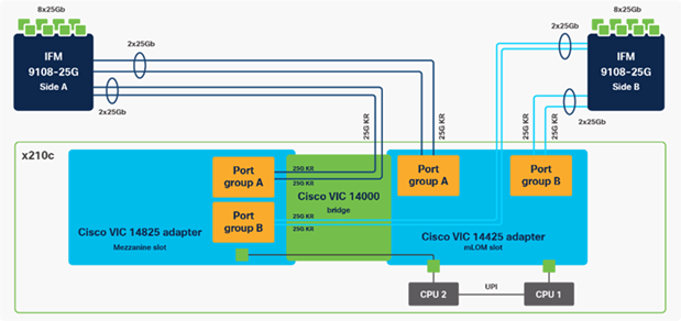
Cisco UCS VIC 14425
The Cisco UCS VIC 14425 is a 4x25-Gbps Ethernet/FCoE capable modular L AN On Motherboard (mLOM) designed exclusively for Cisco UCS X210 Compute Node. The Cisco UCS VIC 14425 enables a policy-based, stateless, agile server infrastructure that can present to the host PCIe standards-compliant interfaces that can be dynamically configured as either NICs or HBAs.
Figure 8. Cisco UCS VIC High-Level Configuration option with Cisco UCS VIC14225 or Cisco UCS VIC14825
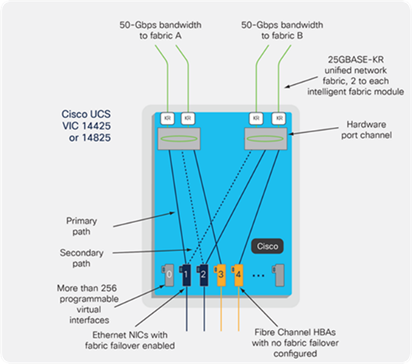
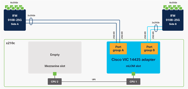
Figure 9. Single Cisco UCS VIC 14425 in Cisco UCS X210c M6
Cisco UCS VIC 14825
The optional Cisco UCS VIC 14825 fits the mezzanine slot on the server. A bridge card (UCSX-V4-BRIDGE) extends this VIC’s 2x 50 Gbps of network connections up to the mLOM slot and out through the mLOM’s IFM connectors, bringing the total bandwidth to 100 Gbps per fabric for a total bandwidth of 200 Gbps per server.
Figure 10. Cisco VIC 14425 and 14825 in Cisco UCS X210c M6
Cisco UCS VIC 1467
The Cisco UCS VIC 1467 is a quad-port Small Form-Factor Pluggable (SFP28) mLOM card designed for the M6 generation of Cisco UCS C-Series Rack Servers. The card supports 10/25-Gbps Ethernet or FCoE. The card can present PCIe standards-compliant interfaces to the host, and these can be dynamically configured as either NICs or HBA
Cisco UCS VIC 1477
The Cisco UCS VIC 1477 is a dual-port Quad Small Form-Factor (QSFP28) mLOM card designed for the M6 generation of Cisco UCS C-Series Rack Servers. The card supports 40/100-Gbps Ethernet or FCoE. The card can present PCIe standards-compliant interfaces to the host, and these can be dynamically configured as NICs or HBAs.
Cisco UCS 15000 Series Virtual Interface Cards (VICs)
The Cisco UCS VIC 15000 series is designed for Cisco UCS X-Series M6 and M7 Compute Nodes Cisco UCS C-Series M6 and M7 Rack Servers. The adapters are capable of supporting 10/25/50/100/200-Gigabit Ethernet and Fibre Channel over Ethernet (FCoE). They incorporate Cisco’s next-generation Converged Network Adapter (CNA) technology and offer a comprehensive feature set, providing investment protection for future feature software releases.
The Cisco UCS VIC 15000 series can support 512 PCI Express (PCIe) virtual devices, either virtual network interface cards (vNICs) or virtual Host Bus Adapters (vHBAs), with a high rate of I/O operations per second (IOPS), support for lossless Ethernet, and 10/25/50/100/200-Gbps connection to servers. The PCIe Generation 4 x16 interface helps ensure optimal bandwidth to the host for network-intensive applications, with a redundant path to the fabric interconnects. Cisco UCS VICs support NIC teaming with fabric failover for increased reliability and availability. In addition, it provides a policy-based, stateless, agile server infrastructure for your data center.
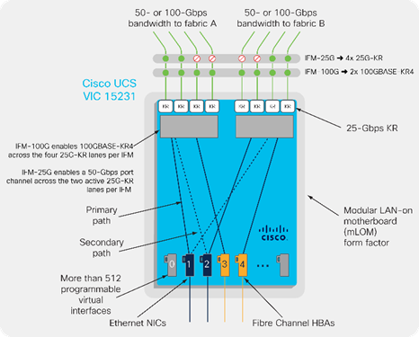
Cisco UCS VIC 15231
The Cisco UCS VIC 15231 is a 2x100-Gbps Ethernet/FCoE capable modular LAN on motherboard (mLOM) designed exclusively for the Cisco UCS X210 Compute Node. The Cisco UCS VIC 15231 enables a policy-based, stateless, agile server infrastructure that can present to the host PCIe standards-compliant interfaces that can be dynamically configured as either NICs or HBAs.
Figure 11. Single Cisco UCS VIC 15231 in Cisco UCS X210c
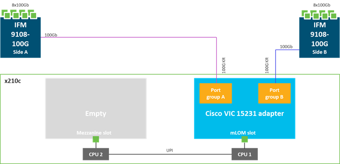
The Cisco UCS VIC 15000 series is capable to work with 25Gbps and 100Gbps Intelligent Fabric Modules as shown in Figure 12.
Figure 12. Cisco UCS VIC Configuration option with VIC15231
Cisco UCS VIC 15428
The Cisco UCS VIC 15428 is a quad-port Small Form-Factor Pluggable (SFP+/SFP28/SFP56) mLOM card designed for the M6 generation of Cisco UCS C-series rack servers. The card supports 10/25/50-Gbps Ethernet or FCoE. The card can present PCIe standards-compliant interfaces to the host, and these can be dynamically configured as either NICs or HBAs.
Cisco Unified Computing System X-Series
The Cisco UCS X-Series Modular System is designed to take the current generation of the Cisco UCS platform to the next level with its future-ready design and cloud-based management. Decoupling and moving the platform management to the cloud allows Cisco UCS to respond to customer feature and scalability requirements in a much faster and efficient manner. Cisco UCS X-Series state of the art hardware simplifies the data center design by providing flexible server options. A single server type, supporting a broader range of workloads, results in fewer different data-center products to manage and maintain.
Figure 13. Cisco UCS X9508 Chassis
Cisco UCS X9508 Chassis
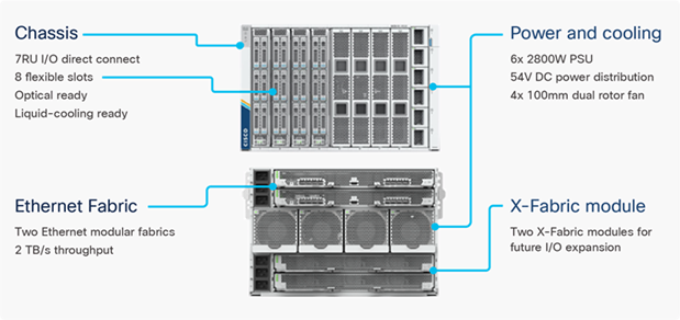
The Cisco UCS X-Series chassis is engineered to be adaptable and flexible. As seen in Figure 14 Cisco UCS X9508 chassis has only a power-distribution midplane. This innovative design provides fewer obstructions for better airflow. For I/O connectivity, vertically oriented compute nodes intersect with horizontally oriented fabric modules, allowing the chassis to support future fabric innovations. Cisco UCS X9508 Chassis’ superior packaging enables larger compute nodes, thereby providing more space for actual compute components, such as memory, GPU, drives, and accelerators. Improved airflow through the chassis enables support for higher power components, and more space allows for future thermal solutions (such as liquid cooling) without limitations.
Figure 14. Cisco UCS X9508 Chassis – Innovative Design
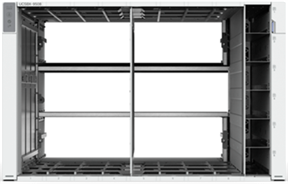
The Cisco UCS X9508 7-Rack-Unit (7RU) chassis has eight flexible slots. These slots can house a combination of compute nodes, GPU accelerators and a pool of future I/O resources that may include disk storage, and memory. At the top rear of the chassis are two Intelligent Fabric Modules (IFMs) that connect the chassis to upstream Cisco UCS 6400 or 6500 Series Fabric Interconnects. At the bottom rear of the chassis are slots ready to house future X-Fabric modules that can flexibly connect the compute nodes with I/O devices. Six 2800W Power Supply Units (PSUs) provide 54V power to the chassis with N, N+1, and N+N redundancy. A higher voltage allows efficient power delivery with less copper and reduced power loss. Efficient, 100mm, dual counter-rotating fans deliver industry-leading airflow and power efficiency, and optimized thermal algorithms enable different cooling modes to best support the customer’s environment.
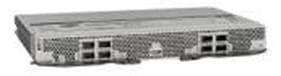
Cisco UCSX 9108-25G Intelligent Fabric Modules
For the Cisco UCS X9508 Chassis, network connectivity is provided by a pair of Cisco UCSX 9108-25G Intelligent Fabric Modules (IFMs). Like the fabric extenders used in the Cisco UCS 5108 Blade Server Chassis, these modules carry all network traffic to a pair of Cisco UCS 6400 Series Fabric Interconnects (FIs). IFMs also host the Chassis Management Controller (CMC) for chassis management. In contrast to systems with fixed networking components, Cisco UCS X9508’s midplane-free design enables easy upgrades to new networking technologies as they emerge making it straightforward to accommodate new network speeds or technologies in the future.
Figure 15. Cisco UCSX 9108-25G Intelligent Fabric Module
![]()
Each IFM supports eight 25Gb uplink ports for connecting the Cisco UCS X9508 Chassis to the FIs and 32 25Gb server ports for the eight compute nodes. IFM server ports can provide up to 200 Gbps of unified fabric connectivity per compute node across the two IFMs. The uplink ports connect the chassis to the UCS FIs, providing up to 400Gbps connectivity across the two IFMs. The unified fabric carries management, VM, and Fibre Channel over Ethernet (FCoE) traffic to the FIs, where management traffic is routed to the Cisco Intersight platform, FCoE traffic is forwarded to the native Fibre Channel interfaces through unified ports on the FI (to Cisco MDS switches), and data Ethernet traffic is forwarded upstream to the data center network (using Cisco Nexus switches).
Note: The current design was validated with Cisco UCSX 9108-25G IFMs.
Cisco UCS 9108-100G Intelligent Fabric Modules (for 100Gbps connectivity support)
In the end-to-end 100Gbps Ethernet design, for the Cisco UCS X9508 Chassis, the network connectivity is provided by a pair of Cisco UCS 9108-100G Intelligent Fabric Modules (IFMs). Like the fabric extenders used in the Cisco UCS 5108 Blade Server Chassis, these modules carry all network traffic to a pair of Cisco UCS 6536 Fabric Interconnects (FIs). IFMs also host the Chassis Management Controller (CMC) for chassis management.
Figure 16. Cisco UCS 9108-100G Intelligent Fabric Module
Each IFM supports eight 100Gb uplink ports for connecting the Cisco UCS X9508 Chassis to the Cisco UCS fifth generation 6556 FIs and 8 100Gb server ports for the eight compute nodes. IFM server ports can provide up to 200 Gbps of unified fabric connectivity per compute node across the two IFMs. The uplink ports connect the chassis to the UCS FIs, providing up to 1600Gbps connectivity across the two IFMs.
Cisco UCS X210c Compute Node
The Cisco UCS X9508 Chassis is designed to host up to 8 Cisco UCS X210c Compute Nodes. The hardware details of the Cisco UCS X210c M6 Compute Nodes are shown in Figure 17:
Figure 17. Cisco UCS X210c M6 Compute Node
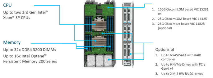
The Cisco UCS X210c M6 features:
· CPU: Up to 2x 3rd Gen Intel Xeon Scalable Processors with up to 40 cores per processor and 1.5 MB Level 3 cache per core.
· Memory: Up to 32 x 256 GB DDR4-3200 DIMMs for a maximum of 8 TB of main memory. The Compute Node can also be configured for up to 16 x 512-GB Intel Optane persistent memory DIMMs for a maximum of 12 TB of memory.
· Disk storage: Up to 6 SAS or SATA drives can be configured with an internal RAID controller, or customers can configure up to 6 NVMe drives. 2 M.2 memory cards can be added to the Compute Node with RAID 1 mirroring.
· Virtual Interface Card (VIC): Up to 2 VICs including an mLOM Cisco VIC 15231 or an mLOM Cisco VIC 14425 and a mezzanine Cisco VIC card 14825 can be installed in a Compute Node.
· Security: The server supports an optional Trusted Platform Module (TPM). Additional security features include a secure boot FPGA and ACT2 anticounterfeit provisions.
Cisco UCS C-Series Rack Servers
Cisco UCS C-Series Rack Servers deliver unified computing in an industry-standard form factor to reduce TCO and increase agility. Each server addresses varying workload challenges through a balance of processing, memory, I/O, and internal storage resources.
Cisco UCS C220 M6 Rack Servers
The Cisco UCS C220 M6 Rack Server shown in Figure 18, is a high-density 2-socket rack server that is an upgrade from the Cisco UCS C220 M5.
Figure 18. Cisco UCS C220 M6 Rack Server
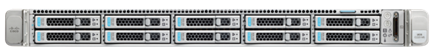
It features the following:
· 3rd Gen Intel Xeon Scalable and Intel Xeon Scalable processors, 2-socket.
· Up to 32 DDR4 DIMMs for improved performance with up to 16 DIMM slots ready for Intel Optane DC Persistent Memory.
· Up to 10 Small-Form-Factor (SFF) 2.5-inch drives or 4 Large-Form-Factor (LFF) 3.5-inch drives.
· Support for 12-Gbps SAS modular RAID controller in a dedicated slot, leaving the remaining PCIe Generation 4.0 slots available for other expansion cards.
· Modular LAN-On-Motherboard (mLOM) slot that can be used to install a Cisco UCS Virtual Interface Card (VIC) without consuming a PCIe slot.
· Dual embedded Intel x550 10GBASE-T LAN-On-Motherboard (LOM) ports.
· Up to 200 Gbps of I/O throughput with Cisco UCS 6454 FI.
For more information about the Cisco UCS C220 M6 Blade Servers see: https://www.cisco.com/c/en/us/products/servers-unified-computing/ucs-c-series-rack-servers/ucs-c220-m6-rack-server-ds.html.
Cisco UCS C240 M6 Rack Servers
The Cisco UCS C220 M6 rack server shown in Figure 19, is a high-density 2-socket rack server that is an upgrade from the Cisco UCS C220 M5.
Figure 19. Cisco UCS C240 M6 Rack Server
It features the following:
· 3rd Gen Intel Xeon Scalable and Intel Xeon Scalable processors, 2-socket.
· Up to 32 DDR4 DIMMs for improved performance with up to 16 DIMM slots ready for Intel Optane DC Persistent Memory.
· Up to 28 Small-Form-Factor (SFF) 2.5-inch drives or 16 Large-Form-Factor (LFF) 3.5-inch drives.
· Support for 12-Gbps SAS modular RAID controller in a dedicated slot, leaving the remaining PCIe Generation 4.0 slots available for other expansion cards.
· Modular LAN-On-Motherboard (mLOM) slot that can be used to install a Cisco UCS Virtual Interface Card (VIC) without consuming a PCIe slot.
· Dual embedded Intel x550 10GBASE-T LAN-On-Motherboard (LOM) ports.
· Up to 100 Gbps of I/O throughput with Cisco UCS 6454 FI.
For more information about the Cisco UCS C240 M6 Blade Servers see: https://www.cisco.com/c/en/us/products/collateral/servers-unified-computing/ucs-c-series-rack-servers/ucs-c240-m6-rack-server-ds.html.
Cisco UCS Scalability in FlexPod
The scale of Cisco UCS in the context of FlexPod is possible in scale-up and scale-out, based on performance, high availability, and locality requirements. A single UCS Domain can scale up to 160 server nodes with any mixture of blade and rack server options. The key KPI limiting the scale-up option is the required network bandwidth from/to the servers in the UCS domain. The more ports are used to connect servers, the fewer ports are available to connect the Cisco UCS Fabric Interconnects to the next-hop network switches. The use of multiple UCS Domains within one FlexPod is not only limited to bandwidth requirements if multiple rooms in the data center are used to deploy FlexPod, such as to provide better high availability or limited impact to the FlexPod in case of environmental issues.
In addition to local scale options, FlexPod is also supported as dual-site and multi-site deployments with multiple NetApp storages and Cisco UCS Domains. Some of the deployment options will be shown in the Deployment Option Chapter in this document.
Graphics Processing Units or GPUs are specialized processors designed to render images, animation and video for computer displays. They perform these tasks by running many operations simultaneously. While the number and kinds of operations they can do are limited, GPUs can run many thousand operations in parallel making this massive parallelism extremely useful for deep learning applications. Deep learning relies on GPU acceleration for both training and inference and GPU accelerated datacenters deliver breakthrough performance with fewer servers at a lower cost.
NVIDIA A100 Tensor Core GPU
The NVIDIA A100 Tensor Core GPU is based on the NVIDIA Ampere GPU architecture and delivers unprecedented acceleration at every scale for AI, data analytics, and HPC. The A100 supports PCIe Express Gen 4, which doubles the bandwidth of PCIe 3.0/ 3.1 by providing 31.5 GBps versus 15.75 GBps for x16 connections. This increase in speed is beneficial for A100 GPUs connecting to PCIe 4.0-capable CPUs and to support fast network interfaces. The Multi-Instance GPU (MIG) feature expands the performance and value of each A100 GPU. It can securely partition the A100 GPU into as many as seven separate GPU Instances, each fully isolated with its own high-bandwidth memory, cache, and compute cores for CUDA applications, providing multiple users with separate GPU resources to accelerate their applications and development projects. This feature enables multiple networks to operate concurrently on a single A100 GPU for optimal utilization of compute resources. Each of the seven instance’s streaming multiprocessors has separate and isolated paths through the entire memory system. This ensures that an individual’s workload can run with predictable throughput and latency even if other tasks are saturating their limits. MIG provides the flexibility to choose from many different instance sizes for each workload. This promotes optimal utilization of the GPU and maximizes ROI. You can use the GPU Instances on a single GPU for different purposes, such as training, inference, and high-performance computing (HPC) all at the same time, with guaranteed quality of service (QoS) around latency and throughput.
For more information, see the NVIDIA A100 product page.
NVIDIA H100 Tensor Core GPU
The NVIDIAH100 Tensor Core GPU delivers unprecedented acceleration to power the world’s highest-performing elastic data centers for AI, data analytics, and high-performance computing (HPC) applications. NVIDIA H100 Tensor Core technology supports a broad range of math precisions, providing a single accelerator for every compute workload. The NVIDIA H100 PCIe supports double precision (FP64), single-precision (FP32), half precision (FP16), and integer (INT8) compute tasks. NVIDIA H100 Tensor Core graphics processing units (GPUs) for mainstream servers comes with an NVIDIA AI Enterprise five-year software subscription and includes enterprise support, simplifying AI adoption with the highest performance. This ensures organizations have access to the AI frameworks and tools needed to build H100 accelerated AI workflows such as conversational AI, recommendation engines, vision AI, and more. Activate NVIDIA AI Enterprise license for H100 here: https://www.nvidia.com/activate-h100/
Figure 20. NVIDIA H100 GPU-PCIe
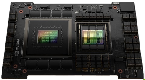
The NVIDIA H100 card is a dual-slot 10.5 inch PCI Express Gen5 card based on the NVIDIA Hopper architecture. It uses a passive heat sink for cooling, which requires system airflow to operate the card properly within its thermal limits. The NVIDIA H100 PCIe operates unconstrained up to its maximum thermal design power (TDP) level of 350 W to accelerate applications that require the fastest computational speed and highest data throughput. The NVIDIA H100 PCIe debuts the world’s highest PCIe card memory bandwidth greater than 2,000 gigabytes per second (Gbps). This speeds time to find solution for the largest models and most massive data sets. The NVIDIA H100 PCIe card features Multi-Instance GPU (MIG) capability. This can be used to partition the GPU into as many as seven hardware-isolated GPU instances, providing a unified platform that enables elastic data centers to adjust dynamically to shifting workload demands. As well as one can allocate the right size of resources from the smallest to biggest multi-GPU jobs. NVIDIA H100 versatility means that IT managers can maximize the utility of every GPU in their data center.
NVIDIA L4 GPU
The NVIDIA Ada Lovelace L4 Tensor Core GPU delivers universal acceleration and energy efficiency for video, AI, virtualized desktop, and graphics applications in the enterprise, in the cloud, and at the edge. With NVIDIA’s AI platform and full-stack approach, L4 is optimized for inference at scale for a broad range of AI applications, including recommendations, voice-based AI avatar assistants, generative AI, visual search, and contact center automation to deliver the best personalized experiences.
It is a half-height (low profile), half-length, single slot card featuring 24 GB of GDDR6 memory, x16 PCIe Gen4 connectivity at a 72 W maximum power envelope. It is a passively cooled card with a superior thermal design-requiring system airflow to operate and handles challenging ambient environments with ease (NEBS-3 capable).
For more information, see the NVIDIA L4 product page.
NVIDIA L40S GPU
The NVIDIA L40S GPU is the most powerful universal GPU for the data center, delivering end-to-end acceleration for the next generation of AI-enabled applications—from generative AI and model training and inference to 3D graphics, rendering, and video applications. The L40S GPU is optimized for 24/7 enterprise data center operations and designed, built, tested, and supported by NVIDIA to ensure maximum performance, durability, and uptime. The L40S GPU meets the latest data center standards, is Network Equipment-Building System (NEBS) Level 3 ready, and features secure boot with root of trust technology, providing an additional layer of security for data centers.
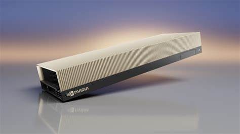
The NVIDIA L40S card is a dual-slot 10.5 inch PCI Express Gen4 card based on the NVIDIA Ada Lovelace architecture. It uses a passive heat sink for cooling, which requires system airflow to operate the card properly within its thermal limits. The NVIDIA L40S PCIe operates unconstrained up to its maximum thermal design power (TDP) level of 350 W to accelerate applications that require fast computational speed and high data throughput.
NVIDIA AI Enterprise is an end-to-end, secure AI software platform that accelerates the data science pipeline and streamlines the development and deployment of production AI. The software layer of the NVIDIA AI platform, NVIDIA AI Enterprise, accelerates the data science pipeline and streamlines the development and deployment of production AI including generative AI, computer vision, speech AI and more. With over 50 frameworks, pre-trained models, and development tools, NVIDIA AI Enterprise is designed to accelerate enterprises to the leading edge of AI while simplifying AI to make it accessible to every enterprise.
Cisco Nexus series switches provide an Ethernet switching fabric for communications between the Cisco UCS, NetApp storage controllers, and the rest of a customer’s network. There are many factors to consider when choosing the main data switch in this type of architecture to support both the scale and the protocols required for the resulting applications. All Cisco Nexus switch models of the Cisco Nexus 9000 series are supported in the FlexPod design. However, be aware that there may be slight differences in setup and configuration based on the switch used. The validation for this deployment leverages the Cisco Nexus 9000 series fixed switch configuration, which deliver high-performance 10/25/40/50/100/400GbE ports, density, low latency, and exceptional power efficiency in a broad range of compact form factors.
Many of the most recent FlexPod designs also use this switch due to the advanced feature set and the ability to support Application Centric Infrastructure (ACI) mode. When leveraging ACI fabric mode, the Cisco Nexus 9000 series switches are deployed in a spine-leaf architecture. Although the reference architecture covered in this design does not leverage ACI, it lays the foundation for customer migration to ACI in the future and fully supports ACI today if required.
For more information, go to: http://www.cisco.com/c/en/us/products/switches/nexus-9000-series-switches/index.html.
This FlexPod design deploys a single pair of Cisco Nexus 9000 series switches like the Cisco Nexus 93240YC-FX2 top-of-rack switch (Figure 22) within each placement, using the traditional standalone mode running NX-OS.
Figure 22. Cisco Nexus 93240YC-FX2
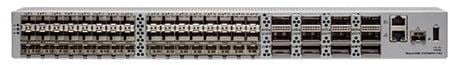
For larger-scale deployment with a single pair of Cisco Nexus 9000 switches, the Cisco Nexus 93360YC-FX2 provides more ports and throughput.
Figure 23. Cisco Nexus 933360YC-FX2 Switch
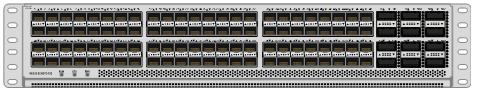
The Cisco Nexus 93360YC-FX2 Switch is a 2RU switch that supports 7.2 Tbps of bandwidth and 2.4 bpps. The 96 downlink ports on the 93360YC-FX2 can support 1-, 10-, or 25-Gbps Ethernet or 16- or 32-Gbps Fibre Channel ports, offering deployment flexibility and investment protection. The 12 uplink ports can be configured as 40- or 100-Gbps Ethernet, offering flexible migration options. This switch was chosen for this solution because of the extra flexibility and scaling the 12 40- or 100-Gbps uplink ports offer.
The Cisco Nexus 93180YC-FX, 93360YC-FX2, and 9336C-FX2-E switches now support SAN switching, allowing both Ethernet and Fibre Channel SAN switching in a single switch. In addition to 16- or 32-Gbps Fibre Channel, these switches also support 100-Gbps FCoE, allowing port-channeled 100-Gbps FCoE uplinks from the Cisco UCS Fabric Interconnects to Cisco Nexus switches in SAN switching mode.
Cisco Nexus Dashboard Fabric Controller (NDFC) is an application deployed on top of a Cisco Nexus Dashboard installation and can monitor, configure, and analyze Cisco Nexus 9000 switching fabrics. Cisco Nexus Dashboard is deployed as a virtual appliance from an OVA, as a physical appliance, or on top of a Linux operating system, and is managed through a web browser. Once the Cisco Nexus switches are added with the appropriate credentials and licensing, monitoring the Ethernet fabric can begin. The NDFC application introduces the Spine-Leaf based Easy Fabric which configures a VXLAN/BGP EVPN network fabric and supports the connection to remote sites and public cloud providers through Cisco Nexus Dashboard Orchestrator.
Cisco Nexus Dashboard Orchestrator (NDO) is an application deployed on top of Cisco Nexus Dashboard. It configures multi-fabric, multi-site, and hybrid-cloud connections for Cisco Nexus Dashboard and ACI based networks.
Cisco Nexus Dashboard Insights (NDI) is an application deployed on top of Cisco Nexus Dashboard.
Cisco Nexus Dashboard integration with Cisco Intersight
The Cisco Network Dashboard Insights (NDI) application provides several TAC assist functionalities that are useful when working with Cisco TAC. The Cisco NDI app collects the CPU, device name, device product id, serial number, version, memory, device type, and disk usage information for the nodes in the fabric. The Cisco NDI application is connected to the Cisco Intersight cloud portal through a device connector which is embedded in the management controller of the Cisco Nexus Dashboard platform. The device connector provides a secure way for the connected Cisco Nexus Dashboard to send and receive information from the Cisco Intersight portal, using a secure Internet connection.
Cisco MDS 9132T 32G Multilayer Fabric Switch
The Cisco MDS 9132T 32G Multilayer Fabric Switch is the next generation of the highly reliable, flexible, and low-cost Cisco MDS 9100 Series switches. It combines high performance with exceptional flexibility and cost effectiveness. This powerful, compact one Rack-Unit (1RU) switch scales from 8 to 32 line-rate 32 Gbps Fibre Channel ports.
Figure 24. Cisco MDS 9132T 32G Multilayer Fabric Switch
![]()
The Cisco MDS 9132T delivers advanced storage networking features and functions with ease of management and compatibility with the entire Cisco MDS 9000 family portfolio for reliable end-to-end connectivity. This switch also offers state-of-the-art SAN analytics and telemetry capabilities that have been built into this next-generation hardware platform. This new state-of-the-art technology couples the next-generation port ASIC with a fully dedicated network processing unit designed to complete analytics calculations in real time. The telemetry data extracted from the inspection of the frame headers are calculated on board (within the switch) and, using an industry-leading open format, can be streamed to any analytics-visualization platform. This switch also includes a dedicated 10/100/1000BASE-T telemetry port to maximize data delivery to any telemetry receiver, including Cisco Data Center Network Manager.
Cisco NDFC-SAN can be used to monitor, configure, and analyze Cisco 32Gbps Fibre Channel fabrics and show information about the Cisco Nexus switching fabric. Cisco NDFC-SAN is deployed as a virtual appliance from an OVA and is managed through a web browser. Once the Cisco MDS and Cisco Nexus switches are added with the appropriate credentials and licensing, monitoring of the SAN and Ethernet fabrics can begin. Additionally, VSANs, device aliases, zones, and zone sets can be added, modified, and deleted using the NDFC point-and-click interface. Device Manager can also be used to configure the Cisco MDS switches. SAN Analytics can be added to Cisco MDS switches to provide insights into the fabric by allowing customers to monitor, analyze, identify, and troubleshoot performance issues.
Cisco NDFC-SAN integration with Cisco Intersight
The Cisco Network Insights Base (Cisco NI Base) application provides several TAC assist functionalities which are useful when working with Cisco TAC. The Cisco NI Base app collects the CPU, device name, device product id, serial number, version, memory, device type, and disk usage information for the nodes in the fabric. Cisco NI Base application is connected to the Cisco Intersight cloud portal through a device connector which is embedded in the management controller of the Cisco NDFC platform. The device connector provides a secure way for connected Cisco NDFC-SAN to send and receive information from the Cisco Intersight portal, using a secure Internet connection.
NetApp AFF A-Series controller lineup provides industry leading performance while continuing to provide a full suite of enterprise-grade data services for a shared environment across on-premises data centers and the cloud. Powered by NetApp ONTAP data management software, NetApp AFF A-Series systems deliver the industry’s highest performance, superior flexibility, and best-in-class data services and cloud integration to help customers accelerate, manage, and protect business-critical data on-prem and across hybrid clouds. As the first enterprise-grade storage systems to support both NVMe over Fibre Channel (FC-NVMe) and NVMe over TCP (NVMe-TCP), AFF A-Series systems boost performance with modern network connectivity. These systems deliver the industry’s lowest latency for an enterprise all-flash array, making them a superior choice for running the most demanding workloads and applications. With a simple software upgrade to the modern FC-NVMe or NVMe-TCP SAN infrastructure, customers can run more workloads, with faster response times, and without disruption or data migration.
NetApp offers a wide range of AFF-A series controllers to meet varying demands of the field. This solution design covers midrange, most versatile NetApp AFF A400 system featuring hardware acceleration technology that significantly enhances performance and storage efficiency.
For more information about the NetApp AFF A-series controllers, see the AFF product page: https://www.netapp.com/us/products/storage-systems/all-flash-array/aff-a-series.aspx.
Download technical specifications of the AFF A-series controllers here: https://www.netapp.com/us/media/ds-3582.pdf
NetApp AFF A800 and A400 have been chosen for solution validation although any other AFF series could be used instead.
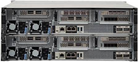
NetApp AFF A400
The NetApp AFF A400 offers full end-to-end NVMe support. The frontend FC-NVMe connectivity makes it possible to achieve optimal performance from an all-flash array for workloads that include artificial intelligence, machine learning, and real-time analytics as well as business-critical databases. On the back end, the A400 supports both serial-attached SCSI (SAS) and NVMe-attached SSDs, offering the versatility for current customers to move up from their legacy A-Series systems and satisfying the increasing interest that all customers have in NVMe-based storage.
The NetApp AFF A400 offers greater port availability, network connectivity, and expandability. The NetApp AFF A400 has 10 PCIe Gen3 slots per high availability pair. The NetApp AFF A400 offers 25GbE or 100GbE, as well as 32Gb/FC and FC-NVMe network connectivity. This model was created to keep up with changing business needs and performance and workload requirements by merging the latest technology for data acceleration and ultra-low latency in an end-to-end NVMe storage system.
Note: Cisco UCS X-Series, like Cisco UCS 5108, is supported with all NetApp AFF systems running NetApp ONTAP 9 release.
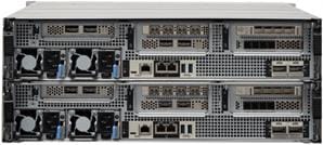
Figure 25. NetApp AFF A400 Front View
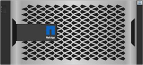
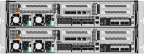
Figure 26. NetApp AFF A400 Rear View
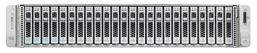
NetApp AFF A800
The NetApp AFF A800 is a higher end model that offers superior performance and higher port count (both 32G FC and 100G Ethernet) than AFF A400. AFF A800 single chassis HA Pair supports 48 internal SSD drives and up to 8 external NS224 shelves allowing up to 240 NVMe SSD drives. It offers ultra-low latency of 100us and up to 300 GB/s throughput enabling it to be an ultimate choice to power data hungry applications such as artificial intelligence, deep learning, and big data analytics.
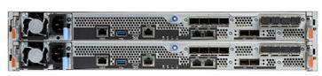
Figure 27. NetApp AFF A800 Front View
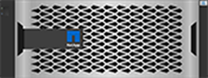
Figure 28. NetApp AFF A800 Rear View
For more information about the NetApp AFF A-series controllers, see the AFF product page: https://www.netapp.com/us/products/storage-systems/all-flash-array/aff-a-series.aspx.
You can view or download more technical specifications of the AFF A-series controllers here: https://www.netapp.com/us/media/ds-3582.pdf
Note: Cisco UCS X-Series is supported with all NetApp AFF systems running NetApp ONTAP 9 release.
NetApp AFF C-Series Storage systems help move more data to flash with the latest high-density NVMe QLC capacity flash technology. These systems are suited for large-capacity deployment with a small footprint as an affordable way to modernize data center to all flash and also connect to the cloud. Powered by NetApp ONTAP data management software, NetApp AFF C-Series systems deliver industry-leading efficiency, superior flexibility, and best-in-class data services and cloud integration to help scale IT infrastructure, simplify data management, reduce storage cost, rack space usage, power consumption, and improve sustainability significantly.
NetApp offers several AFF-C series controllers to meet varying demands of the field. The high-end NetApp AFF C800 systems offer superior performance. The midrange NetApp AFF C400 delivers high performance and good expansion capability. The entry-level NetApp AFF C250 system balanced performance, connectivity, and expansion options for a small footprint deployment.
NetApp AFF C250
The NetApp AFF C250 is an entry-level small form-factor capacity flash model. The 2U dual-controller system supports 24 internal drives for space efficient deployment. The NetApp AFF C250 offers scale-out performance, storage expansion, flexibility in network connectivity, and a rich set of data management and data protection capabilities powered by NetApp ONTAP software.
The NetApp AFF C250 offers both 25 GbE and 100 GbE Ethernet connectivity as well as 32Gb FC connectivity for deploying reliable Ethernet and FC solutions. By adding external NVMe expansion shelves for additional NVMe QLC SSD, the platform is capable of meeting the substantial capacity needs of the data centers.
Figure 29. NetApp AFF C250 Front View

Figure 30. NetApp AFF C250 Rear View
NetApp AFF C400
The NetApp AFF C400 is a midrange model which offers full end-to-end NVMe support. The frontend FC-NVMe and NVMe-TCP connectivity enables you to take advantage of NVMe technology over existing FC and Ethernet infrastructure for faster host connectivity. On the back end, the NetApp AFF C400 supports both serial-attached SCSI (SAS) and NVMe-attached SSDs, offering the versatility for you to move up from your existing systems and adopt NVMe-based storage.
Compared to the entry-level NetApp AFF C250 model, the NetApp AFF C400 offers greater port availability, network connectivity, and expandability. The NetApp AFF C400 has 10 PCIe Gen3 slots per high availability pair. The NetApp AFF C400 offers 10GbE, 25GbE and 100GbE ports for IP based transport, and 16/32Gb ports for FC and FC-NVMe traffic.
Figure 31. NetApp AFF C400 Front View
Figure 32. NetApp AFF C400 Rear View
NetApp AFF C800
The NetApp AFF C800 is a higher end model that offers superior performance and higher port count (both 32G FC and 100G Ethernet) than NetApp AFF C400. The NetApp AFF C800 single chassis HA Pair supports 48 internal SSD drives and up to 8 external NS224 shelves allowing up to 240 NVMe SSD drives. It is an ultimate choice to power data hungry applications such as artificial intelligence, deep learning, and big data analytics.
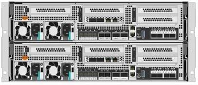
Figure 33. NetApp AFF C800 Front View
Figure 34. NetApp AFF C800 Rear View
For more information about the NetApp AFF C-series controllers, see the NetApp AFF C-Series product page: https://www.netapp.com/data-storage/aff-c-series/
You can view or download more technical specifications of the NetApp AFF C-Series controllers here: https://www.netapp.com/media/81583-da-4240-aff-c-series.pdf
NetApp ASA- ALL SAN ARRAY systems deliver a simplified and dedicated SAN experience for mission-critical databases and other SAN workloads. Built on an end-to-end NVMe architecture, the NetApp ASA systems deliver industry-leading availability, superior performance, and simplified data management across your hybrid cloud. Driven by the combination of high throughput and low latency, the family of NetApp ASA arrays are primed to take on any SAN workloads. Multi-tasking is not a problem. These systems stay sharp even while encrypting, compressing, deduplicating, and protecting your data.
A trusted SAN environment with the powerful ASA systems can:
· Support both FC-NVMe and NVMe-TCP, providing consistent low latency and millions of IOPS in a cluster
· Accelerate your Oracle, SAP, Microsoft SQL Server, and VMware applications to improve customer experience and reduce time to results.
· Meet the performance objectives for all your applications even while encrypting, replicating, and storing the data efficiently. Deliver as low as 100 microsecond response times to your applications with NVMe/FC.
For more information about NetApp ASA, see the NetApp ASA product page: https://www.netapp.com/data-storage/all-flash-san-storage-array/
You can find the detailed NetApp storage product configurations and limits here: https://hwu.netapp.com/
Note: FlexPod CVD provides reference configurations and there are many more supported IMT configurations that can be used for FlexPod deployments, including NetApp hybrid storage arrays.
NetApp ONTAP 9.13.1
NetApp storage systems harness the power of ONTAP to simplify the data infrastructure from edge, core, and cloud with a common set of data services and 99.9999 percent availability. NetApp ONTAP 9 data management software from NetApp enables customers to modernize their infrastructure and transition to a cloud-ready data center. ONTAP 9 has a host of features to simplify deployment and data management, accelerate and protect critical data, and make infrastructure future-ready across hybrid-cloud architectures.
NetApp ONTAP 9 is the data management software that is used with the NetApp AFF A400 all-flash storage system in this solution design. ONTAP software offers secure unified storage for applications that read and write data over block- or file-access protocol storage configurations. These storage configurations range from high-speed flash to lower-priced spinning media or cloud-based object storage. ONTAP implementations can run on NetApp engineered FAS or AFF series arrays and in private, public, or hybrid clouds (NetApp Private Storage and NetApp Cloud Volumes ONTAP). Specialized implementations offer best-in-class converged infrastructure, featured here as part of the FlexPod Datacenter solution or with access to third-party storage arrays (NetApp FlexArray virtualization). Together these implementations form the basic framework of the NetApp Data Fabric, with a common software-defined approach to data management, and fast efficient replication across systems. FlexPod and ONTAP architectures can serve as the foundation for both hybrid cloud and private cloud designs.
Simplify Data Management
Data management is crucial to enterprise IT operations so that appropriate resources are used for applications and for datasets. ONTAP includes the following features to streamline and simplify operations and reduce the total cost of operation:
· Inline data compaction, compression, and deduplication. Compression delivers the primary benefit for alpha-numeric data often used in ML/DL workloads. Data compaction reduces wasted space inside storage blocks, and deduplication significantly increases effective capacity.
· Minimum, maximum, and adaptive quality of service (QoS). Granular QoS controls help maintain performance levels for critical applications in highly shared environments and allows production and development to share infrastructure with guaranteed allocation of resources.
Read more about all the capabilities of ONTAP data management software here: https://www.netapp.com/us/products/data-management-software/ontap.aspx.
See the ONTAP 9 release notes for more information about specific features and what’s new, here: ONTAP 9 Release Notes (netapp.com)
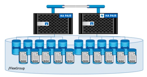
NetApp FlexGroup Volumes
A FlexGroup volume provides a massive single namespace that operates best for workloads that contain numerous small files or metadata operations. An AI training or learning dataset is typically a vast collection of files (sometimes billions) that can include structured data, unstructured data, or a combination of both. The GPUs across multiple servers process this data in parallel, which requires data to be served from a storage system that can allow parallel processing.
FlexGroup volumes provide parallelized operations in a scale-out NAS environment across CPUs, controller nodes, aggregates, and the constituent member NetApp FlexVol volumes. Additionally, FlexGroup volumes provide Automatic Load Balancing (ALB) by using all the resources available in the storage cluster and can scale to multiple petabytes of capacity, offering optimal performance.
NetApp Active IQ Unified Manager
NetApp Active IQ Unified Manager is a comprehensive monitoring and proactive management tool for NetApp ONTAP systems to help manage the availability, capacity, protection, and performance risks of the storage systems and virtual infrastructure. The NetApp Active IQ Unified Manager can be deployed on a Linux server, a Windows server, or as a virtual appliance on a VMware host.
NetApp Active IQ Unified Manager enables monitoring ONTAP storage clusters from a single redesigned, intuitive interface that delivers intelligence from community wisdom and AI analytics. It provides comprehensive operational, performance, and proactive insights into the storage environment and the virtual machines running on it. When an issue occurs on the storage infrastructure, Unified Manager can notify storage admins about the details of the issue to help identify the root cause. The virtual machine dashboard provides performance statistics for the VM so that users can investigate the entire I/O path from the vSphere host down through the network and finally to the storage. Some events also provide remedial actions that can be taken to rectify the issue. Custom alerts can be configured for events so that when issues occur, notifications are sent using email or using SNMP Traps. Active IQ Unified Manager enables planning for the storage requirements by forecasting capacity and usage trends to proactively act before issues arise.
For more information on NetApp Active IQ Unified Manager, go to: https://docs.netapp.com/us-en/active-iq-unified-manager/
Astra Trident with Astra Control Provisioner
Astra Trident is an open-source, fully supported storage orchestrator for containers created by NetApp. It has been designed from the ground up to help you meet your containerized applications’ persistence demands using industry-standard interfaces, such as the Container Storage Interface (CSI). With Astra Trident, microservices and containerized applications can take advantage of enterprise-class storage services provided by the full NetApp portfolio of storage systems. In a FlexPod environment, Astra Trident is utilized to allow end users to dynamically provision and manage persistent volumes for containers backed by FlexVols and LUNs hosted on ONTAP-based products such as NetApp AFF and FAS systems.
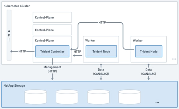
Astra Trident runs as a single Controller Pod plus a Node Pod on each worker node in the cluster. The node pod must be running on any host where you want to potentially mount an Astra Trident volume. Astra Trident deploys as a single Trident Controller Pod and one or more Trident Node Pods on the Kubernetes cluster and uses standard Kubernetes CSI Sidecar Containers to simplify the deployment of CSI plugins. Kubernetes CSI Sidecar Containers are maintained by the Kubernetes Storage community.
Kubernetes node selectors and tolerations and taints are used to constrain a pod to run on a specific or preferred node. You can configure node selectors and tolerations for controller and node pods during Astra Trident installation.
· The controller plugin handles volume provisioning and management, such as snapshots and resizing.
· The node plugin handles attaching the storage to the node.
Figure 36. Astra Trident deployed on the Kubernetes cluster
Astra Trident versions 23.10 and later include the option to use Astra Control Provisioner, which enables licensed Astra Control users to access advanced storage provisioning functionality. Astra Control Provisioner provides this extended functionality in addition to standard Astra Trident CSI-based functionality.
NetApp Astra Control Center offers a rich set of storage and application-aware data management services for stateful Kubernetes workloads deployed in an on-premises environment and hybrid cloud environment powered by NetApp data protection technology.
Astra Control offers critical capabilities for Kubernetes application data lifecycle management:
· Automatically manage persistent storage
· Create application-aware, on-demand snapshots and backups
· Automate policy-driven snapshot and backup operations
· Replicate application to a remote system using NetApp SnapMirror technology
· Migrate applications and data from one Kubernetes cluster to another
· Easily clone an application from production to staging
· Visualize application health and protection status
· Work with a web UI or an API to implement your backup and migration workflows
Figure 37. Astra Control Center Overview
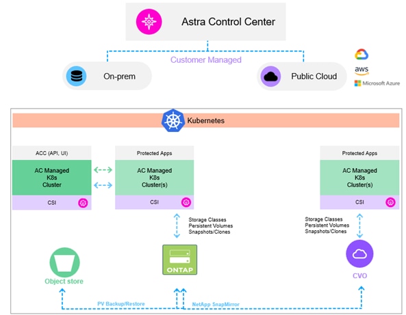
Note: With the 23.10 release, Astra Control introduces a new software component called Astra Control Provisioner that will be available to all licensed Astra Control users
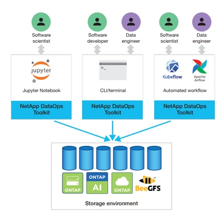
The NetApp DataOps Toolkit is a Python library that makes it easy for developers, data scientists, and data engineers to perform numerous data management tasks. These tasks include provisioning a new data volume or development workspace, cloning a data volume or development workspace almost instantaneously, and creating a NetApp Snapshot copy of a data volume or development workspace for traceability and baselining. This Python library can function as either a command-line utility or a library of functions that can be imported into any Python program or Jupyter Notebook.
The DataOps Toolkit supports Linux and macOS hosts. The toolkit must be used in conjunction with a NetApp data storage system or service. It simplifies various data management tasks that are executed by the data storage system or service. To facilitate this simplification, the toolkit communicates with the data storage system or service through an API.
The NetApp DataOps Toolkit for Kubernetes abstracts storage resources and Kubernetes workloads up to the data-science workspace level. These capabilities are packaged in a simple, easy-to-use interface that is designed for data scientists and data engineers. Using the familiar form of a Python program, the Toolkit enables data scientists and engineers to provision and destroy JupyterLab workspaces in just seconds. These workspaces can contain terabytes, or even petabytes, of storage capacity, enabling data scientists to store all their training datasets directly in their project workspaces. Gone are the days of separately managing workspaces and data volumes.
Figure 38. NetApp Data Science Toolkit
 .
.
SUSE Rancher Enterprise Container Management
The SUSE Rancher Enterprise Container Management (ECM) helps enterprises accelerate their digital transformation using the industry’s most innovative cloud-native technologies to build, scale, secure, and manage your enterprise-grade applications faster from core to cloud to edge. While entirely based upon open source, leveraging Rancher Prime Subscription for enterprise support provides comprehensive value, ensuring your workload, extracting more value, and strengthening your container strategy with exclusive access to professional services and our rich knowledge base, plus:
· Multi-cluster Kubernetes everywhere
· Maintain your cluster’s operational reliability everywhere across any certified Kubernetes distribution and ensure Day 2 cluster operations with certified support and value-adding services
· Security, policy management and compliance
· Implement a security-first container strategy, deploying from a trusted private registry and minimizing misconfigurations across your clusters with access to pre-written Kubewarden policies
· Clone of extensible platform with shared tools and services
Enrich your organization’s Kubernetes through the catalog of integrations and new UI extensions framework by deploying tools from the app catalog or implement custom, peer-developed or built-in certified & supported extensions.
A Kubernetes cluster consists of one or more masters and a set of worker nodes. This solution design includes HA functionality at the hardware as well as the software stack. A Kubernetes cluster is designed to run in HA mode with 3 master nodes, which includes control plane and etcd services, and a minimum of 2 or more worker nodes to help ensure that the cluster has no single point of failure. Rancher Kubernetes Engine Government (RKE2) is the next generation Rancher Kubernetes Engine specifically engineered by the Rancher Government Solutions (RGS) team to meet the needs of our federal customers and anyone desired a fully secured Kubernetes environment. RKE2 leverages the best of previous RKE distribution and edge-focused K3s, to provide a complete DISA STIG certified Kubernetes distribution. RKE2 is easy to install and secure by default, RKE2 is built to run on mission critical infrastructure on prem, in the cloud or at the edge.
SUSE Linux Enterprise Server
SUSE Linux Enterprise Server (SLES) is a secure, adaptable and easy-to-manage Linux server platform that allows developers and administrators to deploy business-critical workloads on-premises, in the cloud and at the edge. When it comes to relying on a single Linux OS to run all your application workloads, SUSE Linux Enterprise Server adapts to any operating environment while satisfying your requirements for performance, security, and reliability – purpose-built for your needs.
The modern and modular OS helps simplify your IT environment, modernize your IT infrastructure, and accelerate innovation. Many organizations use traditional infrastructure, software defined infrastructure, or a mix of traditional and software defined. This leads to a hybrid IT scenario, where different types of IT infrastructure have different technologies, processes, and business drivers. SUSE Linux Enterprise server, with its multimodal design, helps organizations transform their IT landscape by bridging traditional and software defined infrastructure.
· Simplify your IT environment.
The SUSE Linux Enterprise “common code base” platform helps break the silos of IT systems while bridging traditional and software-defined infrastructure. This enables easy migration of application workloads, improves systems management, protects your investments in traditional infrastructure, and eases adoption of containers.
· Modernize your IT infrastructure.
Improve efficiency and innovate without disrupting the traditional IT infrastructure pillars - stability, security, and proven standards. Architecturally, everything is a module. So, you can get product updates and patches more frequently. The modular architecture helps an IT administrator reduce risk by simplifying planning and decision making. Starting with one installation image, you can add SUSE Linux Enterprise Server products or add modules with ease as your business needs grow. With the cloud-agnostic design of SUSE Linux Enterprise and Bring-Your-Own Subscription, you can easily transition to or leverage public cloud - Alibaba, Azure, AWS, Google, IBM, Oracle.
· Accelerate innovation.
Make it easy for your DevOps teams to adopt opensource software with support for automation, project builds and message-oriented middleware. Accelerate your innovation by connecting with the developer community at SUSE Package Hub. Once you are ready to move to from development sandbox to production you can seamlessly transition from our community Linux distribution - openSUSE Leap - to SUSE Linux Enterprise. Meet the needs of the modern developer and DevOps teams with management and monitoring features such as RabbitMQ, Prometheus and Maven.
SUSE Linux Enterprise Micro
SUSE Linux Enterprise (SLE) Micro is a lightweight and secure operating system. It merges the enterprise-hardened components of SUSE Linux Enterprise with the features that developers want in a modern, immutable operating system. As a result, you get a reliable infrastructure platform with best-in-class compliance that is also simple to use. Its flexible subscription model makes SUSE Linux Enterprise Micro well-suited for any edge, embedded, or Internet of Things deployment and does not create vendor lock-in. Using SUSE Linux Enterprise Micro, you can build and scale systems across a wide range of industries including aerospace, telecom, automotive, defense, healthcare, and manufacturing. SLE Micro includes the following:
· A read-only root file system: This means that after the deployment is complete, you are not able to perform direct modifications to the root file system. Instead, SLE Micro introduces the concept of transactional updates, with snapshots, which enables you to modify your system and keep it up to date. When a snapshot is created, both the snapshot and the original subvolume point to the same blocks in the file system. So, initially, a snapshot does not occupy additional disk space. If data in the original file system is modified, changed data blocks are copied while the old data blocks are kept for the snapshot. Booting from snapshots and thus allows you to use any older functional snapshot in case the new snapshot does not work correctly.
· Multiple kinds of workloads: use of rpm-based packages plus downloading, creating, running and containers and virtual machines
· Security: leveraging SELinux, remote attestation using Keylime, and compliance with FIPS
Ansible Automation
Ansible Automation helps SUSE Rancher ECM users create and run reusable infrastructure code and automate provisioning tasks for infrastructure components.
Ansible is simple and powerful, allowing users to easily manage various physical devices within FlexPod, including the provisioning of Cisco UCS bare metal servers, Cisco Nexus switches, and NetApp AFF storage. Using Ansible’s Playbook-based automation is easy and integrates into your current provisioning infrastructure.
Finally, Ansible also provides robust container and native Kubernetes management, expanding to SUSE Rancher ECM and other container technologies.
VMware vSphere is a virtualization platform for holistically managing large collections of infrastructures (resources including CPUs, storage, and networking) as a seamless, versatile, and dynamic operating environment. Unlike traditional operating systems that manage an individual machine, VMware vSphere aggregates the infrastructure of an entire data center to create a single powerhouse with resources that can be allocated quickly and dynamically to any application in need.
For more information about VMware vSphere and its components, see: https://www.vmware.com/products/vsphere.html.
VMware vSphere vCenter
VMware vCenter Server provides unified management of all hosts and VMs from a single console and aggregates performance monitoring of clusters, hosts, and VMs. VMware vCenter Server gives administrators a deep insight into the status and configuration of compute clusters, hosts, VMs, storage, the guest OS, and other critical components of a virtual infrastructure. VMware vCenter manages the rich set of features available in a VMware vSphere environment.
Cisco Intersight integrates with VMware vCenter, NetApp Storage, Cisco Nexus and MDS switches, as follows:
· Cisco Intersight uses the device connector running within Cisco Intersight Assist virtual appliance to communicate with the VMware vCenter.
· Cisco Intersight uses the device connector running within a Cisco Intersight Assist virtual appliance to integrate with NetApp Active IQ Unified Manager. The NetApp AFF A400 should be added to NetApp Active IQ Unified Manager.
· Cisco Intersight uses the device connector running within the Cisco Intersight Assist virtual appliance to communicate with Cisco Nexus 9000 switches.
Figure 39. Cisco Intersight and vCenter/NetApp Integration
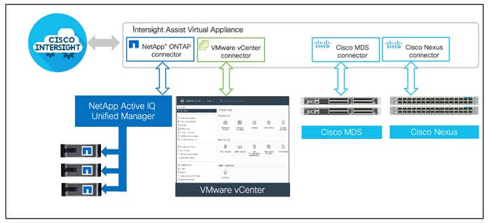
The device connector provides a secure way for connected targets to send information and receive control instructions from the Cisco Intersight portal using a secure internet connection. The integration brings the full value and simplicity of Cisco Intersight infrastructure management service to VMware hypervisor and ONTAP data storage environments.
Enterprise SAN and NAS workloads can benefit equally from the integrated management solution. The integration architecture enables FlexPod customers to use new management capabilities with no compromise in their existing Cisco switching, VMware or ONTAP operations. IT users will be able to manage heterogeneous infrastructure from a centralized Cisco Intersight portal. At the same time, the IT staff can continue to use VMware vCenter, NetApp Active IQ Unified Manager, and Cisco NX-OS command line interface (CLI) for comprehensive analysis, diagnostics, and reporting of virtual and storage environments. The functionality provided through this integration is covered in the upcoming solution design section.
FlexPod
FlexPod is available as Cisco Intersight Integrated System that groups the FlexPod components (Cisco UCS, NetApp ONTAP storage, Cisco switches, and VMware vCenter) into an Integrated System. This grouping enhances full-stack visibility and provides FlexPod-level dashboards and widgets within the stack. For current information on FlexPod, see: https://www.cisco.com/c/en/us/products/collateral/servers-unified-computing/ucs-x-series-modular-system/flexpod-xcs-solution-with-intersight-wp.html.
Figure 40. FlexPod in Cisco Intersight
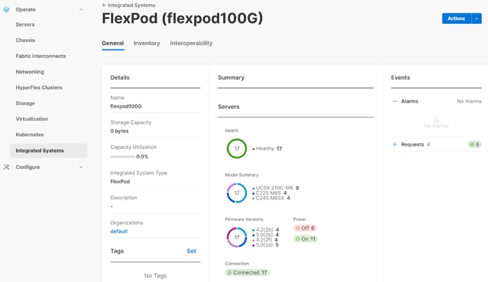
Infrastructure as Code with Ansible
This FlexPod solution provides a fully automated solution deployment that covers all sections of the infrastructure and application layer. The configuration of the NetApp ONTAP Storage, Cisco Network and Compute, and VMware layers are automated by leveraging Ansible playbooks that have been developed to setup the components as per the solution best practices that were identified during the testing and validation.
The automated deployment using Ansible provides a well-defined sequence of execution across the different constituents of this solution. Certain phases of the deployment also involve the exchange of parameters or attributes between compute, network, storage, and virtualization and also involve some manual intervention. All phases have been clearly demarcated and the implementation with automation is split into equivalent phases via Ansible playbooks with a ‘tag’ based execution of a specific section of the component’s configuration.
Figure 41. Infrastructure as Code with Ansible
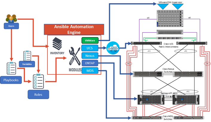
As illustrated in Figure 41 the Ansible playbooks to configure the different sections of the solution invoke a set of Roles and consume the associated variables that are required to setup the solution. The variables needed for this solution can be split into two categories – user input and defaults/ best practices. Based on the installation environment customers can choose to modify the variables to suit their requirements and proceed with the automated installation.
Note: The automation for ONTAP is scalable in nature that can configure anywhere from a single HA pair to a fully scaled 24 node ONTAP cluster.
DataOps for Data Scientist
With the NetApp DataOps Toolkit, a data scientist can almost instantaneously create a space-efficient data volume that’s an exact copy of an existing volume regardless of the size of the dataset. Data scientists can quickly create clones of datasets that they can reformat, normalize, and manipulate, while preserving the original “gold-source” dataset. Under the hood, these operations use highly efficient and battle-tested NetApp FlexClone feature, but they can be performed by a data scientist without storage expertise. What used to take days or weeks (and the assistance of a storage administrator) now takes seconds.
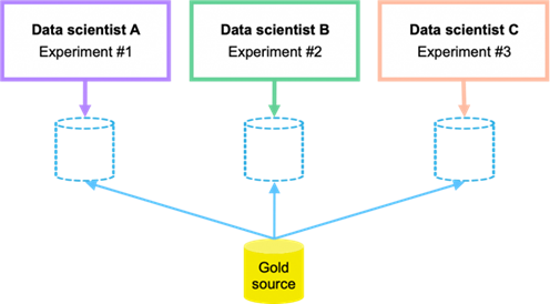
Data scientists can also save a space-efficient, read-only copy of an existing data volume. Based on the famed NetApp Snapshot technology, this functionality can be used to version datasets and implement dataset-to-model traceability. In regulated industries, traceability is a baseline requirement, and implementing it is extremely complicated with most other tools. With the NetApp DataOps Toolkit, it’s quick and easy.
More operations and capabilities are available and documented here: https://github.com/NetApp/netapp-data-science-toolkit
Natural Language Processing and Computer Vision for Next Generation AI
A simplified AI data management infrastructure is imperative for faster natural language processing (NLP). For real-time natural language processing, data must be able to flow quickly and freely throughout each step of your data pipeline. With FlexPod AI powered by NVIDIA and NetApp All flash storage systems massive, state-of-the-art language models can be trained and optimized to perform inference rapidly.
Organizations across a wide range of industries are using computer vision and machine learning to gain valuable insights from the massive amounts of data they generate. Computer vision programs are trained on thousands, millions, or billions of images. Computer vision requires real-time response in milliseconds to tackle high-pressure, real-life scenarios.
The validated architecture from FlexPod is capable of running any AI workload ranging from Healthcare, Retail, Fintech, Automotive, Education etc. addressing any analytics and trending needs companies are looking for. The solution from FlexPod is designed to scale to any dataset size meeting the dynamic needs of business.
This chapter contains the following:
· FlexPod Network Connectivity and Design
· Cisco MDS SAN Connectivity - Fibre Channel Design Only
· FlexPod Compute Connectivity
· Fabric Failover for Ethernet: Architecture for High Availability
· FlexPod Storage Design for RKE2
· Kubernetes Virtual Switching Architecture
· Bare Metal Compute Options and Sizing
· Secure Multi-Tenancy / Multi-Tenancy
· Management Design Considerations
The FlexPod Datacenter for SUSE Rancher Enterprise Container Management provides an end-to-end architecture with Cisco and NetApp technologies that demonstrate support for K8s workloads with high availability and server redundancy. The architecture supports the deployment of SUSE Rancher Kubernetes Engine Government (RKE2) as bare metal cluster or virtualized on top of supported virtual machine monitors like VMware vSphere or KVM on Cisco UCS servers within FlexPod infrastructure, with the Cisco UCS servers and NetApp storage attached to the Cisco Nexus switches in NXOS mode.
Figure 43 illustrates a sample design with the required management components, like Intersight Assist or Active IQ Unified Manager (AIQUM), installed on the FlexPod stack as virtual machines. Each of the components can be scaled easily to support specific business requirements. For example, additional RKE2 nodes can be deployed to scale the RKE2 environment to increase compute capacity, additional storage controllers or disk shelves can be deployed to improve I/O capability and throughput.
Figure 43. FlexPod Datacenter with SUSE Rancher ECM Architecture View
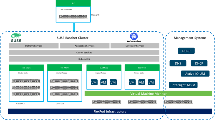
Kubernetes (K8s) Virtualization is an add-on to SUSE RKE2 that allows you to run and manage virtual machine workloads alongside container workloads. The K8s Virtualization feature has been validated within this solution to deploy traditional VMs into SUSE Rancher where they run side by side with containers on the same RKE2 cluster deployed on the FlexPod infrastructure.
Figure 44 illustrates a high-level overview of the FlexPod for RKE2 cluster architecture.
Figure 44. Kubernetes Virtualization
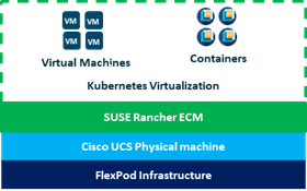
This section explains the key design requirement and various prerequisites for delivering this new solution.
The FlexPod Datacenter with SUSE Rancher ECM solution closely aligns with all FlexPod CVDs and meets the following general design requirements:
· Resilient design across all layers of the infrastructure with no single point of failure.
· Scalable design with the flexibility to add compute capacity, storage, or network bandwidth as needed.
· Modular design that can be replicated to expand and grow as the needs of the business grow.
· Flexible design that can support components beyond what is validated and documented in this guide.
· Simplified design with ability to automate and integrate with external automation and orchestration tools.
For SUSE Rancher ECM integration into a traditional FlexPod solution, the following specific design considerations are also observed:
· Deployment option for one or three master nodes, where the option with one master is only recommended for non-productive installations.
· A minimum of 2 worker nodes with the ability to increase the nodes as the load requirements increase.
· Automating the FlexPod infrastructure deployment and RKE2 installation by utilizing Ansible Playbooks to simplify the installation and reduce the deployment time.
· Present persistent storage (volumes) to the containerized applications by utilizing the NetApp Astra Trident CSI framework.
· Dedicated Cisco UCS vNICs for different traffic needs with UCS Fabric Failover for high availability.
This FlexPod design utilizes Cisco UCS servers connected and managed through Cisco UCS Fabric Interconnects and the Intersight Managed Mode (IMM) to manage the servers. These high-performance servers are configured as compute nodes where SUSE Linux Enterprise (SLE) is loaded using SAN boot leveraging FC or iSCSI LUNs from the NetApp AFF storage, optional the use of local disk for boot is documented. The persistent storage volumes for containers are provisioned on the NetApp AFF A400 using NFS NAS storage and iSCSI storage.
IP-based Storage Access: iSCSI and NFS
Figure 45 illustrates a typical topology for the iSCSI FlexPod Datacenter.
Figure 45. FlexPod Physical Topology
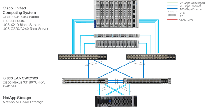
To build an IP-only storage access in a FlexPod configuration, the component set up is as follows:
· Cisco UCS Fabric Interconnects provide the chassis and network connectivity.
· The Cisco UCS X9508 Chassis connects to fabric interconnects using Cisco UCS X9108 Intelligent Fabric Module, where four 25 Gigabit Ethernet ports are used on each IFM to connect to the appropriate Fabric Interconnect. If additional bandwidth is required, all eight 25G ports can be utilized.
· Cisco UCSX-210 M6 Compute Nodes contain fourth-generation Cisco UCS VIC 14425 (VIC).
· Cisco UCS C220 or C240 Servers with fourth-generation Cisco UCS 1457 VICs. VICs connect to the fabric interconnects with 25GE.
· Cisco Nexus 93180YC-FX Switches in Cisco NX-OS mode provide the switching fabric.
· Cisco UCS 6454 Fabric Interconnect 25-Gigabit Ethernet uplink ports connect to Cisco Nexus 93180YC-FX Switches in a Virtual Port Channel (vPC) configuration.
· The NetApp AFF A400 controllers connect to the Cisco Nexus 93180YC-FX Switches using four 25 GE ports from each controller configured as a vPC.
· SUSE ECM and RKE2 software can be installed on Cisco UCS Compute Nodes with local disks or iSCSI LUN from NetApp storage.
FC-based Storage Access: FC, FC-NVMe, and NFS
A typical topology for the FC-booted FlexPod Datacenter is shown in Figure 46.
Figure 46. FlexPod Datacenter Physical Topology for FC, FC-NVMe, and NFS
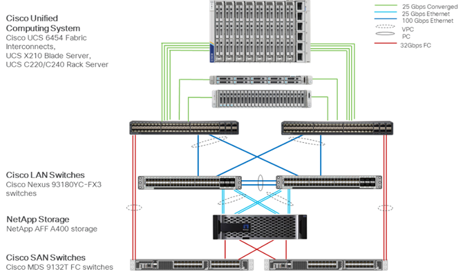
To build an FC-based storage access in a FlexPod configuration, the component set up is as follows:
· Cisco UCS 6454 Fabric Interconnects provide the chassis and network connectivity.
· The Cisco UCS X9508 Chassis connects to fabric interconnects using Cisco UCS X9108 Intelligent Fabric Module, where four 25 Gigabit Ethernet ports are used on each IFM to connect to the appropriate Fabric Interconnect. If additional bandwidth is required, all eight 25G ports can be utilized.
· Cisco UCSX-210 M6 Compute Nodes contain fourth-generation Cisco UCS VIC 14425 (VICs).
· Cisco UCS C22x or C24x Servers with either fourth-generation VICs or fifth-generation Cisco UCS 15428 VICs connect to the fabric interconnects 25GE.
· Cisco Nexus 93180YC-FX3 Switches in Cisco NX-OS mode provide the switching fabric.
· Cisco UCS 6454 Fabric Interconnect 25-Gigabit Ethernet uplink ports connect to Cisco Nexus 93240YC-FX2 Switches in a Virtual Port Channel (vPC) configuration.
· The NetApp AFF A400 controllers connect to the Cisco Nexus 93240YC-FX2 Switches using four 25 GE ports from each controller configured as a vPC for NFS storage access.
· Cisco UCS 6454 Fabric Interconnects are connected to the Cisco MDS 9132T switches using multiple 32-Gbps Fibre Channel connections configured as a single port channel for SAN connectivity.
· The NetApp AFF controllers connect to the Cisco MDS 9132T switches using 32-Gbps Fibre Channel connections for SAN connectivity.
· SUSE Rancher ECM and RKE2 software is installed on Cisco UCS Compute Nodes with FC LUN
· Persistent Storage for containerized applications is provided by NetApp Trident CSI via NFS protocol.
FC-based Storage Access: FC, FC-NVMe, and NFS Utilizing Cisco Nexus SAN Switching
The typical topology for the FC-boot FlexPod Datacenter with Cisco Nexus SAN Switching is shown in Figure 47.
Figure 47. FlexPod Datacenter Physical Topology for FC, FC-NVMe, and NFS
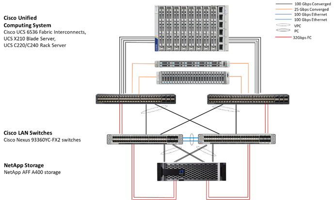
To build a FC-based storage access in a FlexPod configuration with Cisco Nexus SAN switching, the component set up is as follows:
· Cisco UCS 6536 Fabric Interconnects provide the chassis and network connectivity.
· The Cisco UCS X9508 Chassis connects to fabric interconnects using Cisco UCS X9108 Intelligent Fabric Module, where four 25 Gigabit Ethernet ports are used on each IFM to connect to the appropriate Fabric Interconnect. If additional bandwidth is required, all eight 25G ports can be utilized.
· Cisco UCSX-210 M6 Compute Nodes contain fourth-generation Cisco UCS 14425 virtual interface cards (VICs).
· Cisco UCS C22x or C24x Servers with either fourth-generation VICs or fifth-generation Cisco UCS 15428 VICs connect to the fabric interconnects 25GE.
· Cisco Nexus 93360YC-FX2 Switches in Cisco NX-OS mode provide the switching fabric.
· Cisco UCS 6536 Fabric Interconnect 100-Gigabit Ethernet uplink ports connect to Cisco Nexus 93360YC-FX3 Switches in a Virtual Port Channel (vPC) configuration.
· The NetApp AFF A400 controllers connect to the Cisco Nexus 93360YC-FX3 Switches using two 100 GE ports from each controller configured as a vPC for NFS storage access.
· Cisco UCS 6536 Fabric Interconnects are connected to the Cisco Nexus 93360YC-FX3 switches using multiple 32-Gbps Fibre Channel connections configured as a single port channel for SAN connectivity.
· The NetApp AFF controllers connect to the Cisco Nexus 93360YC-FX3 switches using 32-Gbps Fibre Channel connections for SAN connectivity.
· SUSE Rancher ECM and RKE2 software is installed on Cisco UCS Compute Nodes with FC LUN
· Persistent Storage for containerized applications is provided by NetApp Trident CSI via NFS protocol.
VLAN Configuration
Table 1 lists the VLANs configured for setting up the FlexPod environment along with their usage.
| VLAN ID |
Name |
Usage |
| 2 |
Native-VLAN |
Use VLAN 2 as native VLAN instead of default VLAN (1) |
| 1020 |
OOB-MGMT-VLAN |
Out-of-band management VLAN to connect management ports for various devices |
| 1021 |
IB-MGMT-VLAN |
In-band management VLAN utilized for all in-band management connectivity - for example, ESXi hosts, VM management, and so on. |
| RKE2-Traffic1 |
Data traffic VLAN from/to RKE2 cluster 1 |
|
| 1024 |
RKE2-VM1 |
Data traffic VLAN from/to RKE2 Virtual Machines |
| 1027 |
RKE2-NFS1 |
NFS storage traffic VLAN for RKE2 cluster 1 |
| 3050 |
NFS-VLAN |
NFS VLAN for Infrastructure components |
| 2023 |
RKE2-Traffic2 |
Data traffic VLAN from/to RKE2 cluster 2 |
| 2024 |
RKE2-VM2 |
Data traffic VLAN from/to RKE2 Virtual Machines 2 |
| 2027 |
RKE2-NFS2 |
NFS storage traffic VLAN for RKE2 cluster 2 |
| 3010* |
iSCSI-A |
iSCSI-A path for boot-from-san traffic |
| 3020* |
iSCSI-B |
iSCSI-B path for boot-from-san traffic |
| 3030* |
NVMe-TCP-A |
NVMe-TCP-A path for NVMe datastores |
| 3040* |
NVMe-TCP-B |
NVMe-TCP-B path for NVMe datastores |
| 3000 |
vMotion |
VMware vMotion traffic |
* iSCSI, NVMe-TCP, and vMotion VLANs are optional only.
Some of the key highlights of VLAN usage are as follows:
· VLAN 1020 allows you to manage and access out-of-band management interfaces of various devices and is brought into the infrastructure to allow CIMC access to the UCS servers and is also available to infrastructure virtual machines (VMs). Interfaces in this VLAN are configured with MTU 1500.
· VLAN 1021 is used for in-band management of VMs, hosts, and other infrastructure services. Interfaces in this VLAN are configured with MTU 1500.
· VLAN 3050 provides management systems and other infrastructure services access to the NFS storage hosted on the NetApp Controllers. Interfaces in this VLAN are configured with MTU 9000.
· A pair of iSCSI VLANs (3010 and 3020) is configured to provide access to boot LUNs for hosts and iSCSI datastores. These VLANs are not needed when configuring Fibre Channel connectivity. Interfaces in these VLANs are configured with MTU 9000.
· A pair of NVMe-TCP VLANs (3030 and 3040) are configured to provide access to NVMe datastores. These VLANs are not needed when configuring Fibre Channel connectivity. Interfaces in these VLANs are configured with MTU 9000.
· VLAN 1023 is used as access network for RKE2 cluster 1 to access all RKE2 hosts, and services deployed on top. Interfaces in this VLAN are configured with MTU 1500.
· VLAN 1024 is used as an access network for K8s Virtual machines and services deployed on top. Interfaces in this VLAN are configured with MTU 1500.
· VLAN 1027 provides services deployed on top of RKE2 cluster 1access to the NFS storage hosted on the NetApp Controllers managed by NetApp Astra Trident CSI. Interfaces in this VLAN are configured with MTU 9000.
Physical Components
Table 2 lists the required hardware components used to build the validated solution. Customers are encouraged to review their requirements and adjust the size or quantity of various components as needed.
Table 2. FlexPod Datacenter with SUSE Rancher hardware components
| Component |
Hardware |
Comments |
| Cisco Nexus Switches |
Two Cisco Nexus 93000 series switches, such as Cisco Nexus 93240YC -FX |
The switch model is dependent on the number of ports and the port speed required for the planned installation. |
| Cisco MDS Switches |
Two Cisco MDS 9100 series switches, i.e. MDS 9132T |
The supported port speed of the selected MDS switch must match the port speed of the Fabric Interconnect and the NetApp storage. |
| NetApp AFF Storage |
A NetApp AFF series storage with appropriate capacity and network connectivity, i.e. NetApp AFF A400 |
Customer requirements will determine the amount of storage. The NetApp AFF storage should support both 25Gbps or 100 Gbps ethernet and 32Gbps or 16 Gbps FC connectivity |
| Fabric Interconnects |
Two Cisco UCS Fabric Interconnects, such as Cisco UCS 6454 FI |
|
| Management Cluster Compute |
||
| Cisco UCS Servers |
A minimum of two Cisco UCS servers to host management components like Intersight Assist and NetApp Active IQ Unified Manager systems. |
To reduce the number of physical servers the use of a supported virtualization software like VMware ESXi is recommended. |
| SUSE Rancher ECM Compute |
||
| Cisco UCS Chassis |
A minimum of one UCS X9508 chassis. |
Single chassis can host up to 8 Cisco UCS X210c compute nodes |
| Cisco UCS Compute Nodes |
A minimum of three Cisco UCS X210c compute nodes |
Six compute nodes are recommended to build an RKE2 cluster with three control and two worker nodes, but three compute nodes will work to build a three node cluster with combined control and worker function. |
Table 3 lists various software releases used in the solution. The minimum versions of the components listed in Table 3 and additional drivers and software tools (for example, various NetApp software tools, Cisco Intersight Assist and so on) versions will be explained in the deployment guide.
Table 3. Software components and versions
| Component |
Version |
| Cisco Nexus 93240YC-FX |
9.3(10) |
| Cisco MDS 9132T |
8.4(2d) |
| Cisco UCS Fabric Interconnects |
4.2(2a) |
| Cisco UCS X-Series blade server |
5.0(2b) |
| Cisco UCS C-Series rack server |
4.2.2(a) |
| NetApp A400 - ONTAP |
9.13.1 |
| NetApp Astra Trident CSI |
23.10.0 |
| NetApp Astra Control |
23.10.0 |
| NetApp DataOps Toolkit K8s |
2.4.0 |
| SUSE Rancher ECM and RKE2 |
|
| Rancher ECM |
2.7.6 |
| SUSE RKE2 |
v1.26.9+rke2r1 |
| SUSE Linux Enterprise Micro |
5.4 |
Logical Design
The SUSE Rancher deployment is fully automated. Before starting the deployment process, Cisco UCS compute nodes need to be configured with appropriate compute policies (BIOS, for example), Network Interface Card (NIC) and VLAN configuration. All Cisco UCS servers are equipped with a Cisco Virtual Interface Card (VIC) configured for multiple virtual Network Interfaces (vNICs). The server design as well as connectivity including VLAN/VSAN usage between the server profile for an SLE/RKE2 host and the storage configuration on NetApp AFF A400 controllers is captured in the following subsections.
Figure 48 illustrates the FlexPod Datacenter with SUSE Rancher logical topology with RKE2 components utilizing compute, network, and storage resources on FlexPod. The storage and network connectivity to SUSE RKE2 Cluster nodes running on Cisco UCS servers is enabled by the Cisco Nexus 9000 series switches within FlexPod.
Persistent storage is a critical part of running stateful containers, and SUSE Rancher with Kubernetes simplifies storage management by abstracting details of how storage is provisioned and how it is consumed. Persistent volumes for containers can be static or dynamically provisioned, in this case it is dynamic with FlexPod and is enabled by the NetApp Astra Trident CSI Driver. Dynamic volume provisioning allows storage volumes to be created on-demand, NetApp Astra Trident CSI eliminates the need to pre-provision storage for containers and allows persistent storage provisioning during the container deployment. This solution used NFS and iSCSI storage for dynamic storage provisioning.
SUSE Rancher uses a software-defined networking (SDN) approach to provide a unified cluster network that enables communication between pods across the SUSE RKE2 cluster. This pod network is established and maintained by the SUSE RKE2 SDN, which configures an overlay network using Open vSwitch (OVS). The default RKE2 SDN solution is built on top of Open vSwitch (OVS). With RKE2, the cluster admin can choose to deploy with one of the RKE2 native SDN plug-ins or they can opt to deploy the cluster using a third-party SDN from the supported ecosystem such as Cisco ACI. For this solution, we used the RKE2 native SDN plug-in (OVN-Kubernetes).
Figure 48. FlexPod Datacenter for SUSE Rancher Bare Metal Logical Topology
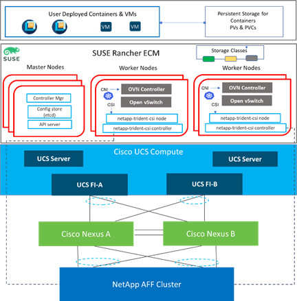
FlexPod Network Connectivity and Design
The Layer 2 network connection to each Fabric Interconnect is implemented as Virtual Port Channels (vPC) from the upstream Cisco Nexus Switches as shown in Figure 49. In the switching environment, the vPC provides the following benefits:
· Allows a single device to use a Port Channel across two upstream devices
· Eliminates Spanning Tree Protocol blocked ports and use all available uplink bandwidth
· Provides a loop-free topology
· Provides fast convergence if either one of the physical links or a device fails
· Helps ensure high availability of the network
The upstream network switches can connect to the Cisco UCS Fabric Interconnects using 10G, 25G, 40G, or 100G port speeds. Virtual port channels were also configured between the Cisco Nexus switches and NetApp AFF storage to also transport the storage traffic between the Cisco UCS servers and the NetApp AFF storage.
Figure 49. Network Connectivity – vPC Enabled Connections
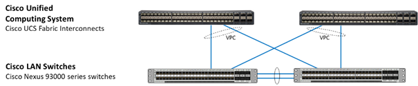
NetApp AFF Storage Ethernet Connectivity
NetApp AFF storage controllers are connected with port channels (NetApp Interface Groups) to Cisco Nexus 93000 series switches using 25GE or 100GE connections configured as virtual port channels. The storage controllers are deployed in a switchless cluster interconnect configuration and are connected to each other using the 100GE ports e0a and e1a. Figure 50 illustrates the physical connectivity details.
In Figure 50, the two storage controllers in the high-availability pair are drawn separately for clarity. Physically, the two controllers exist within a single chassis.
Figure 50. NetApp AFF A800 Ethernet Connectivity
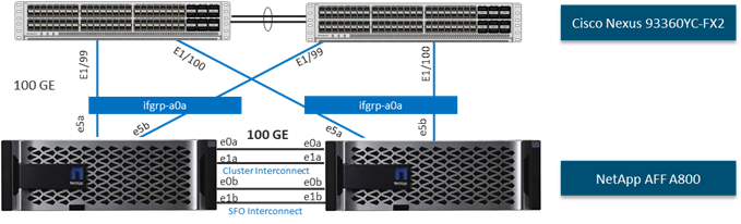
Cisco MDS SAN Connectivity - Fibre Channel Design Only
The Cisco MDS 9132T is the key design component bringing together the 32Gbps Fibre Channel (FC) capabilities to the FlexPod design. A redundant 32 Gbps Fibre Channel SAN configuration is deployed utilizing two MDS 9132Ts switches. Some of the key MDS features implemented within the design are:
· Feature NPIV—N port identifier virtualization (NPIV) provides a means to assign multiple FC IDs to a single N port.
· Feature fport-channel-trunk—F-port-channel-trunks allow for the fabric logins from the NPV switch to be virtualized over the port channel. This provides nondisruptive redundancy should individual member links fail.
· Enhanced Device Alias – a feature that allows device aliases (a name for a WWPN) to be used in zones instead of WWPNs, making zones more readable. Also, if a WWPN for a vHBA or NetApp FC LIF changes, the device alias can be changed, and this change will carry over into all zones that use the device alias instead of changing WWPNs in all zones.
· Smart-Zoning—a feature that reduces the number of TCAM entries and administrative overhead by identifying the initiators and targets in the environment.
Cisco UCS Fabric Interconnect 6536 SAN Connectivity
For SAN connectivity, each Cisco UCS 6536 Fabric Interconnect is connected to a Cisco MDS 9132T SAN switch using a breakout on ports 33-36 to a 4 x 32G Fibre Channel port-channel connection, as shown in Figure 51.
Figure 51. Cisco UCS 6536 FI SAN Connectivity
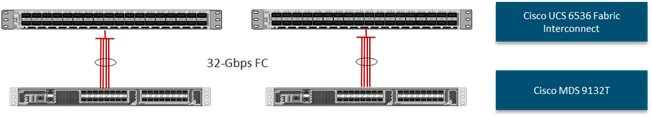
NetApp AFF SAN Connectivity
For SAN connectivity, each NetApp AFF storage controller is connected to both of Cisco MDS 9132T SAN switches using 32G Fibre Channel connections, as shown in Figure 52. FC-NVMe LIFs can be put on the same FC ports on the NetApp storage controllers as FC LIFs.
In Figure 52, the two storage controllers in the high-availability pair are drawn separately for clarity. Physically, the two controllers exist within a single chassis.
Figure 52. NetApp AFF A800 SAN Connectivity
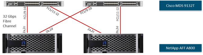
The FlexPod compute design supports Cisco UCS X-Series, B-Series, and C-Series. Cisco UCS supports the SUSE Rancher environment by providing robust, highly available, and integrated compute resources centrally managed from Cisco UCS Manager in the Enterprise or from Cisco Intersight Software as a Service (SaaS) in the cloud. In this validation effort, the Cisco UCS servers are booted from local SSDs, these drives are configured in Raid 1 using a Cisco Raid Controller. Or the Cisco UCS servers are booted from a LUN provided from the NetApp AFF storage over FC or iSCSI. The servers have access to NFS and iSCSI storage for persistent storage volumes presented from the NetApp AFF storage cluster.
Figure 53. Compute Connectivity
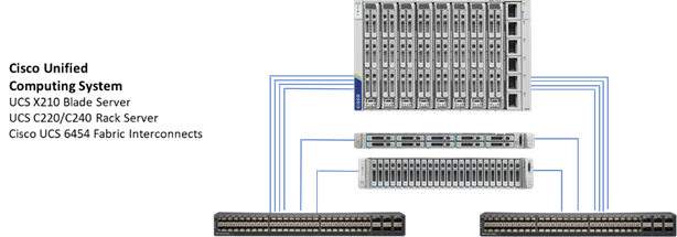
The Cisco UCS chassis in the design are populated with Cisco UCS X210 M7 blade servers and each of these blade servers contain one physical network adapter (VIC) that passes converged fibre channel over Ethernet (FCoE) and Ethernet traffic to the X9108-25 IFM. The IFMs are redundantly connected to the fabric interconnects using 4X25Gbps ports per IFM to deliver an aggregate bandwidth of 200Gbps to the chassis. Full population of each X9108-25 IFM can support 8x25Gbps ports, providing an aggregate bandwidth of 400Gbps to the chassis. The connections from the Cisco UCS Fabric Interconnects to the IFMs are automatically configured as port channels.
The Cisco UCS C-Series nodes are equipped with Cisco UCS VIC 1457 or Cisco UCS PCIe VIC 1455. Cisco UCS VIC 1455/1457 has four 25GbE ports which are connected to the Cisco UCS Fabric Interconnect in pairs such that ports 1 and 2 are connected to the Cisco UCS FI-A and the ports 3 and 4 are connected to the FI-B as shown in Figure 53. Optionally, only ports 1 and 3 from each Cisco UCS VIC 1455/57 and be connected with network bandwidth reduced from 50 Gbps to 25 Gbps to each FI.
Fabric Failover for Ethernet—Architecture for High Availability
Cisco UCS is designed for high availability, with no single point of failure in its network infrastructure. Each adapter in Cisco UCS connects to both fabrics (A and B) and the fabric interconnects are designed to work in an active-active model, with automated failover of network in the event of a failure. The system is designed so that if either fabric A or fabric B fails, the remaining fabric can take on the traffic from the failed fabric. Cisco UCS VICs support fabric failover by moving traffic from one fabric to the other according to failover policies established on a per-vNIC basis. This eliminates complicated operating system NIC teaming configurations. Fabric failover makes the failure of a fabric transparent to the operating system.
Figure 54 illustrates the Cisco UCS Fabric failover mechanism, in this example one vNIC connects to fabric A but fails over to fabric B in the event of a fabric failover.
Cisco UCS Fabric Failover is an important feature because it reduces the complexity of defining NIC teaming software for failover on the host. It does this transparently in the fabric based on the network property that is defined in the server profile. With Cisco UCS fabric failover, NIC teaming is not necessary on the SLE/RKE2 nodes, and the high availability is managed at the UCS level more efficiently.
Figure 54. Cisco UCS Fabric Failover
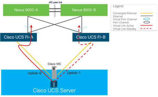
NIC Bonding versus Cisco UCS Fabric Failover
SUSE Rancher network requirements in this design are standard Ethernet only, while RKE2 deployment can work with two network interfaces in bonded mode for each traffic type (bare metal public VLAN and VM network VLAN), it is recommended to use a single network interface for each traffic type and enable Cisco UCS Fabric Failover for resiliency versus NIC bonding in the operating system. With Cisco UCS Fabric Failover the management and operation of failover and link aggregation is handled in the networking fabric. The Fabric Failover is enabled in the vNIC policy within the LAN Connectivity Policy which makes it easy to implement NIC resiliency across any number of servers managed by Cisco UCS, this eliminates the need to configure every server individually.
NIC teaming is often implemented to aggregate lower-speed NICs in order to gain throughput. Since RKE2 design with Cisco UCS leverages 25/100GbE connections, aggregation is generally not required.
Intersight Server Profile for RKE2 Hosts
In FlexPod deployments, each Cisco UCS server (X-Series, B-Series, or C-Series), equipped with a Cisco Virtual Interface Card (VIC), is configured for multiple virtual interfaces (vNICs) which appear as standards-compliant PCIe devices to the OS. The server profile configuration for an RKE2 host is shown in Table 4 and Figure 55 for RKE2 Worker and Master nodes, respectively.
Each RKE2 host server profile supports:
· Managing the RKE2 hosts using a common management segment
· OS local boot using the mirrored onboard disk drives on the Cisco UCS servers or boot from FC LUN
· Five vNICs were used in the following specified order:
° One vNIC for RKE2 Public Bare Metal Network traffic. The bare metal network is a routable network.
° One vNIC for K8s Virtualization VM Network traffic.
° One NFS vNIC for NFS storage traffic. The MTU value for this interface is set as a Jumbo MTU (9000).
° One iSCSI-A vNIC utilizes iSCSI-A VLAN (defined only on Fabric A) to provide access to iSCSI-A path. The MTU value for this interface is set as a Jumbo MTU (9000).
° One iSCSI-B vNIC utilizes iSCSI-B VLAN (defined only on Fabric B) to provide access to iSCSI-B path. The MTU value for this interface is set as a Jumbo MTU (9000).
Table 4. SUSE RKE2 Host Service Profile
| Machine |
BareMetal Public Traffic |
Kubernetes Virtualization |
NFS |
iSCSI-A |
iSCSI-B |
| Master Node |
vNIC2 Fabric-B failover to Fabric-A |
vNIC3 Fabric-A failover to Fabric-B |
vNIC4 Fabric-B failover to Fabric-A |
vNIC0 Fabric-A only |
vNIC1 Fabric-B only |
| Worker Node |
vNIC2 Fabric-B failover to Fabric-A |
vNIC3 Fabric-A failover to Fabric-B |
vNIC4 Fabric-B failover to Fabric-A |
vNIC0 Fabric-A only |
vNIC1 Fabric-B only |
Figure 55. Cisco UCS – Network Interface Design for K8s nodes
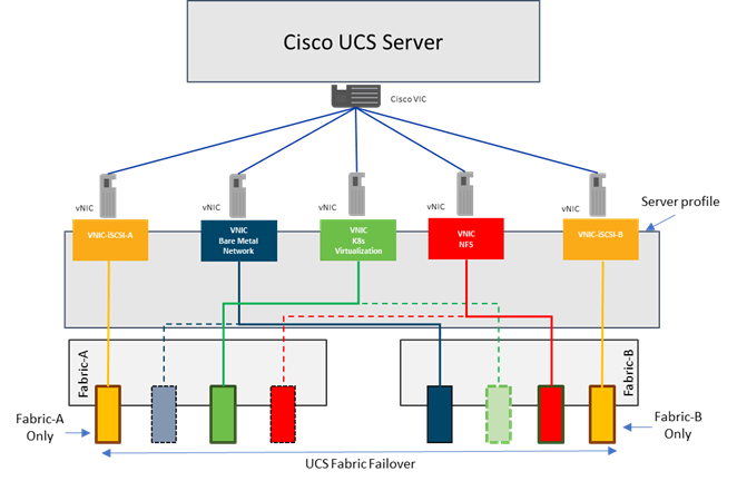
FlexPod Storage Design for RKE2
The FlexPod Datacenter for SUSE Rancher uses the NetApp Astra Trident CSI driver that is an add-on component that needs to be installed on the SUSE RKE2 cluster. Astra Trident enables the integration between the storage and RKE2 cluster.
The NetApp AFF series storage array supports both NFS and iSCSI protocols. For the purpose of this validated design, both NFS and iSCSI were used for dynamic persistent storage for Containers and VMs.
Note: RKE2 provides dynamic provisioning of storage for applications by utilizing the StorageClass resource. Using dynamic storage, you can select different types of back-end storage. The back-end storage is segregated into different tiers depending on the needs of your application. When requesting storage, you can specify a PersistentVolumeClaim with an annotation that specifies the value of the StorageClass they prefer.
To order the storage, you must create a PVC. The PVC determines the specification for the storage that you want to provision. After the PVC is created, the storage device and the PV are automatically created for you.
Figure 56 illustrates how block storage is dynamically provisioned in a cluster. This sample flow works similarly with other storage types, such as file storage.
Figure 56. Dynamic Storage Provisioning Workflow
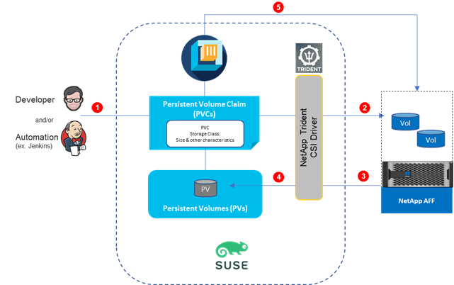
Developer/Automation submits storage requirements in the form of standard Persistent Volume Claims that specifies the storage type, storage class, size, and so on.
NetApp Astra Trident CSI Plugin listens to, and intercepts Persistent Volume Claims based on Storage Class. Creating a PVC in a cluster automatically triggers the storage plug-in for the requested type of storage to provision storage with the given specification.
A storage provisioning API call sent to NetApp AFF, and storage is provisioned.
The storage plug-in automatically creates a persistent volume (PV) in the cluster, a virtual storage device that points to the actual storage device on your NetApp AFF.
The PVC and PV are automatically connected to each other. The status of the PVC and the PV changes to Bound and the PVC is used to mount persistent storage to your app. If you delete the PVC, the PV and related storage instance are also deleted.
With ONTAP, FlexPod you can create a separate storage virtual machine (SVM) for their AI workloads. Aggregates can be assigned to this SVM, from which you can provision FlexGroup volumes to host the dataset. You can create a dedicated set of LIFs for data traffic and map them to data VLAN interfaces reserved for AI operations.
RKE2 Virtual Switching Architecture
The SUSE RKE2 cluster uses a virtualized network for pod and service networks. The Kubernetes Container Network Interface (CNI) plug-in is a network provider for the default cluster network. A cluster that uses the Kubernetes network provider also runs Open vSwitch (OVS) on each node. OVN configures OVS on each node to implement the declared network configuration.
The OVN-Kubernetes default Container Network Interface (CNI) network provider implements the following features:
· Uses OVN (Open Virtual Network) to manage network traffic flows. OVN is a community developed, vendor agnostic network virtualization solution.
· Implements Kubernetes network policy support, including ingress and egress rules.
· Uses the Geneve (Generic Network Virtualization Encapsulation) protocol rather than VXLAN to create an overlay network between nodes.
Figure 57 shows the distribution of network interfaces on each RKE2 worker node with one Open vSwitch bridge, for Pod-to-Pod communication and the other dedicated Linux bridge created for VM external network when VMs are deployed leveraging the K8s Virtualization feature. Each bridge has one NIC within the OS providing access to external networks. The other four network interfaces on the RKE2 nodes are used for communication via the provisioning network and access to NFS, iSCSI-A, and iSCSI-B traffic via dedicated interfaces. Appropriate VLANs are enabled at the UCS level to support different traffic types.
Figure 57. Virtual Switching and Connectivity Diagram for a Cisco UCS K8s Host
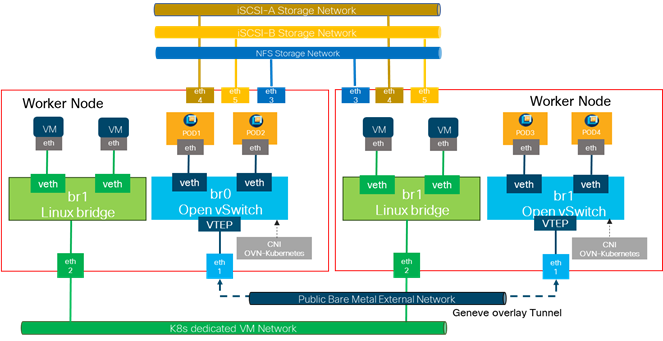
With Kubernetes Virtualization, each VM deployed is controlled via a virt-launcher pod that is created with each VM. The default networking type for Kubernetes Virtualization VMs is Masquerade. The VM will be assigned a non-routable IP, and you can access the VM using the IP of the virt-launcher pod that was deployed alongside it. This makes the VM accessible in the same way that containers are accessed.
Alternatively, you can connect the VM to the host network by creating a bridge interface on the RKE2 nodes using Nmstate. The Nmstate operator is installed with Kubernetes Virtualization and provides you with the Node Network Configuration Policy (NNCP) object to update the host network settings. Figure 57 has a sample config bridge called br1 created from an interface called eth2 (the interface name differs based on how the host views it) on the RKE2 nodes.
Bare Metal Compute Options and Sizing
The validation of FlexPod Datacenter with SUSE Rancher was done with various UCS server models and is not limited to a specific set of server types. It is important to check if the used operating system release is supported on the server and firmware version available in the Cisco UCS Hardware Compatibility List (HCL), and if one of the boot options (local disk or FC LUN) are possible.
Table 5 lists some Cisco UCS compute options that are tested for SUSE Rancher installation.
Table 5. Cisco UCS Server Node Configuration Options
| Server Node |
CPU |
Boot storage |
| Cisco UCS B200 M6 |
2x 3rd Gen Intel Xeon Scalable |
RAID1 on local SSD, FC LUN |
| Cisco UCS C220 M6 |
2x 3rd Gen Intel Xeon Scalable |
RAID1 on local SSD, FC LUN |
| Cisco UCS C225 M6 |
2x 3rd Gen AMD EPYC |
RAID1 on local SSD, FC LUN |
| Cisco UCS X210 M6 |
2x 3rd Gen Intel Xeon Scalable |
RAID1 on local SSD, FC LUN |
| Cisco UCS X210 M7 |
2x 4th Gen Intel Xeon Scalable |
RAID1 on local SSD, FC LUN |
This is a general recommendation and not specific to a customer environment. It is important to properly size the solution with all of its components by a qualified Engineer or Architect per the specific requirements of the customer. There is no one size fits all approach, hence specific sizing and performance testing were excluded from the validation process.
For example, at the Cisco UCS level, customers have the option to include servers with different processors and core counts, and with the combination of the right amount of memory the servers can be optimized for the right cost-performance configuration. The same strategy is applicable across all the layers of FlexPod including network and storage.
It is important to size the servers to meet the minimal requirements of the SUSE Rancher platform, to account for failures of servers and by that to make sure that RKE2 HA related rules can be followed upon server failure with enough resources available for RKE2 to redistribute the workloads from the failing host or when performing upgrades and other maintenance tasks.
Example Sizing Guidelines (Worker Nodes)
Determine how many nodes and pods are required for your RKE2 cluster. Cluster scalability correlates to the number of pods in a cluster environment. That number influences the other numbers in your setup. See Cluster Limits for the latest limits for objects in SUSE Rancher ECM.
Environmental sizing can be done according to tested cluster maximums or according to your application requirements. While planning your environment, determine how many pods are expected to fit per node:
Required Pods per Cluster / Pods per Node = Total Number of Nodes Needed
If you want to scope your cluster at 3000 pods, assuming the 500 maximum pods per node, you will need at least ten nodes:
3000 / 500 = 6
If you increase the number of nodes to 8, the pods per node distribution changes to 375 pods per node.
The current maximum number of pods per node is 500. However, the number of pods that fit on a node is dependent on the application itself. Consider the application’s memory, CPU, and storage requirements.
Table 6 lists components you might consider for a sample application environment.
Table 6. Environment Components
| Pod type |
Pod quantity |
Max memory |
CPU cores |
Persistent storage |
| apache |
100 |
500 MB |
0.5 |
1 GB |
| node.js |
200 |
1 GB |
1 |
1 GB |
| postgresql |
100 |
1 GB |
2 |
10 GB |
The overall resource requirements for this application are: 450 CPU cores, 350GB RAM, and 1.3TB storage plus overhead required for RKE2 operations.
Secure Multi-Tenancy / Multi-Tenancy
Secure Multi-Tenancy defines the deployment option to share the infrastructure resource across multiple tenants/customer/user and separate them so that tenant 1 does have no access to any resources of tenant 2. Such as, tenant 1 is unable to access any storage resources or files of any other tenant stored on the same physical storage. The FlexPod architecture provides all required functions to enable network and storage separation on a logical level.
In the example shown in Figure 58, each RKE2 cluster does have dedicated networks – meaning VLAN IDs and IP ranges, and a dedicated virtual storage server (vserver). All storge networks (iSCSI and NFS) are not routed, meaning not accessible from outside of the configured VLAN ID. The external network and VM network are either routed and controlled by access control lists or firewall rules or mapped to transfer network to the public cloud or remote sites to enable hybrid-cloud operations. To allow central management of all components the RKE2 nodes and storage are connected to the IB-Management network. In case of management dedication – each tenant is maintaining the RKE2 nodes – the IB-Management network can be replaced by dedicated tenant management networks.
Figure 58. Secure Multi-Tenancy Option – Multiple SUSE Rancher RKE2 clusters
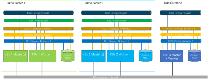
Another option to provide multi-tenancy is combining network and storage separation with SUSE RKE2 configurations as shown in Figure 59. This option can use a single set of RKE2 Master nodes to control multiple sets of worker nodes and manage the separation by labels and tags.
Note: Since there is only one set of RKE2 master nodes, all set of worker nodes must match the RKE2 version requirements of this master.
Figure 59. Secure Mutli-Tenancy Option – Single SUSE RKE2 Cluster with Worker Node Sets
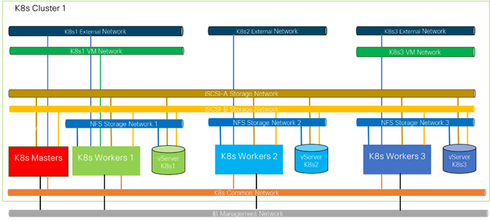
The terminology hybrid cloud can be used for more than one type of solution. One of them is managing hardware deployed on-premises together with resources from the public cloud from a single as a Service “aaS” solution. Or managing workloads deployed at on-premises stack and in the public cloud like production system in the local data center and test or development systems in the public cloud. The FlexPod Datacenter with SUSE Rancher Enterprise Container Management solution works with both options. Cisco Intersight can manage the FlexPod hardware in local data centers and remote locations together with resources from the public cloud like AWS EC2 instances and SUSE Rancher is the single place to manage RKE2 deployments on bare metal infrastructure, virtualized or in the public cloud.
The key aspect of managing distributed workloads or multiple application instances across on-premises and public clouds is the network in between. Deploying and managing the virtual private network (VPN) connection between the locations and control access is an important aspect of every hybrid cloud deployment. This FlexPod Datacenter with SUSE Rancher ECM solution is tested with two key networking solutions from Cisco. The first is Cisco Application Centric Infrastructure (ACI) combined with Cisco Cloud APIC – shown in Figure 60, and the second is Cisco Nexus Dashboard Fabric Controller (NDFC) together with Cisco Nexus Dashboard Orchestrator (NDO) and the Cisco Cloud APIC to deploy and manage workload dependent network connections. With those two options a End-2-end tested, and documented solution is available. There are other networking options available which will work but they will not be tested and documented as part of this solution.
Figure 60. Sample Hybrid Cloud setup – ACI Managed Network Connections
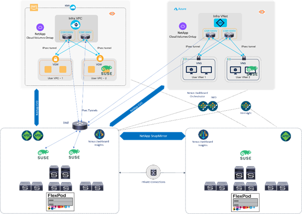
Management Design Considerations
Out-of-band Management Network
The management interface of every physical device in FlexPod is connected to a dedicated out-of-band management switch which can be part of the existing management infrastructure in a customer’s environment. The out-of-band management network provides management access to all the devices in the FlexPod environment for initial and on-going configuration changes. The routing and switching configuration for this network is independent of FlexPod deployment and therefore changes in FlexPod configurations do not impact management access to the devices. In this design, the out-of-band management network is connected to the Cisco Nexus uplinks to allow Cisco UCS CIMC connectivity and to provide the out-of-band management network to management virtual machines (Cisco DCNM) when necessary.
In-band Management Network
The in-band management VLAN configuration is part of FlexPod design. The in-band VLAN is configured on Cisco Nexus switches and Cisco UCS within the FlexPod solution to provide management connectivity for management components deployed on this solution or on a dedicated management system. The changes to FlexPod configuration can impact the in-band management network and misconfigurations can cause loss of access to the management components hosted by FlexPod. It is also required that the out-of-band management network have Layer 3 access to the in-band management network so that management machines with only in-band management interfaces can manage FlexPod hardware devices.
Jumbo Frames
An MTU of 9216 is configured at all network levels to allow jumbo frames as needed by the guest OS and application layer. This allows the network at every point to negotiate an MTU up to 9000 with the end point. For VLANs that leave the FlexPod via the Cisco Nexus switch uplinks (OOB-MGMT, IB-MGMT, K8s-VM), all endpoints should have MTU 1500. For Storage and replication VLANs that stay within the FlexPod, MTU 9000 should be used on all endpoints for higher performance. It is important that all endpoints within a VLAN have the same MTU setting. It is important to remember that most virtual machine network interfaces have MTU 1500 set by default and that it may be difficult to change this setting to 9000, especially on a large number of virtual machines. This difficulty should be considered when implementing storage protocols such as NFS or SMB. Note that a VLAN tagged trunk can contain both VLANs with MTU 1500 and VLANs with MTU 9000 interfaces.
NTP
For many reasons, including authentication and log correlation, it is critical within a FlexPod environment that all components are properly synchronized to a time-of-day clock. In order to support this synchronization, all components of FlexPod support network time protocol (NTP). In the FlexPod setup, the two Cisco Nexus switches are synchronized via NTP to at least two external NTP sources. Cisco Nexus NTP distribution is then set up and all the other components of the FlexPod can use the IP of any of the switches’ L3 interfaces, including mgmt0 as an NTP source. If a customer already has NTP distribution in place, that can be used instead of Cisco Nexus switch NTP distribution.
Boot From SAN
When utilizing Cisco UCS Server technology with shared storage, it is recommended to configure boot from SAN and store the boot partitions on remote storage. This enables architects and administrators to take full advantage of the stateless nature of Cisco UCS Server Profiles for hardware flexibility across the server hardware and overall portability of server identity. Boot from SAN also removes the need to populate local server storage thereby reducing cost and administrative overhead.
UEFI Secure Boot
This validation of FlexPod uses Unified Extensible Firmware Interface (UEFI) Secure Boot. UEFI is a specification that defines a software interface between an operating system and platform firmware. With UEFI secure boot enabled, all executables, such as boot loaders and adapter drivers, are authenticated as properly signed by the BIOS before they can be loaded. Additionally, a Trusted Platform Module (TPM) is also installed in the Cisco UCS compute nodes. SUSE Linux Enterprise supports UEFI Secure Boot and UEFI Secure Boot Attestation between the TPM module and the OS, validating that UEFI Secure Boot has properly taken place.
NetApp Astra Trident
Astra Trident is an open-source and fully supported storage orchestrator for containers and Kubernetes distributions, including SUSE Rancher. Trident works with the entire NetApp storage portfolio, including the NetApp ONTAP storage systems, and it also supports NFS and iSCSI connections. Trident accelerates the DevOps workflow by allowing end users to provision and manage storage from their NetApp storage systems without requiring intervention from a storage administrator.
An administrator can configure a number of storage backends based on project needs and storage system models that enable advanced storage features, including compression, specific disk types, or QoS levels that guarantee a certain level of performance. After they are defined, these backends can be used by developers in their projects to create persistent volume claims (PVCs) and to attach persistent storage to their containers on demand.
Upcoming Publications
FlexPod Datacenter for SUSE Rancher Enterprise Container Management with NetApp Astra
Ulrich Kleidon, Principal Engineer, UCS Solutions, Cisco Systems
Ulrich Kleidon is a Principal Engineer for Cisco's Unified Computing System (Cisco UCS) solutions team and a lead architect for solutions around converged infrastructure stacks, enterprise applications, data protection, software-defined storage, and Hybrid-Cloud. He has over 25 years of experience designing, implementing, and operating solutions in the data center.
Abhinav Singh, Sr. Technical Marketing Engineer, Hybrid Cloud Infra & OEM Solutions, NetApp
Abhinav Singh is Senior Technical Marketing Engineer for FlexPod solutions team and has more than 13 years of experience in Data Center infrastructure solutions which includes On-prem and Hybrid cloud space. He focuses on the designing, validating, implementing, and supporting converged infrastructure and hybrid cloud infrastructure solutions. Abhinav holds a bachelor's degree in electrical and electronics.
Acknowledgements
For their support and contribution to the design, validation, and creation of this Cisco Validated Design, the authors would like to thank:
· Chris O’Brien, Sr. Manager, UCS Solutions, Cisco Systems
· Bryan Gartner, Sr. Technology Strategist, SUSE
· Bobby Oommen, Sr. Manager FlexPod Solutions, NetApp
· Juergen Hamm, Solutions Architect, NetApp
This appendix contains the following:
· Compute
· Network
· Storage
Cisco Intersight: https://www.intersight.com
Cisco Intersight Managed Mode: https://www.cisco.com/c/en/us/td/docs/unified_computing/Intersight/b_Intersight_Managed_Mode_Configuration_Guide.html
Cisco Unified Computing System: http://www.cisco.com/en/US/products/ps10265/index.html
Cisco UCS 6536 Fabric Interconnects: https://www.cisco.com/c/en/us/products/collateral/servers-unified-computing/ucs6536-fabric-interconnect-ds.html
NVIDIA H100 GPU: https://resources.nvidia.com/en-us-tensor-core/nvidia-tensor-core-gpu-datasheet
NVIDIA A100 GPU: https://www.nvidia.com/content/dam/en-zz/Solutions/Data-Center/a100/pdf/nvidia-a100-datasheet-nvidia-us-2188504-web.pdf
NVAIE: https://www.nvidia.com/en-in/data-center/products/ai-enterprise/
NVAIE Product Support Matrix: https://docs.nvidia.com/ai-enterprise/latest/product-support-matrix/index.html#support-matrix__suse-linux-enterprise-server
Cisco Nexus 9000 Series Switches: http://www.cisco.com/c/en/us/products/switches/nexus-9000-series-switches/index.html
Cisco MDS 9132T Switches: https://www.cisco.com/c/en/us/products/collateral/storage-networking/mds-9100-series-multilayer-fabric-switches/datasheet-c78-739613.html
NetApp ONTAP: https://docs.netapp.com/ontap-9/index.jsp
NetApp AFF A series: https://www.netapp.com/data-storage/aff-a-series/ss
NetApp Astra Trident: https://docs.netapp.com/us-en/trident/
NetApp Astra Control Center: https://docs.netapp.com/us-en/astra-control-center/index.html
NetApp Active IQ Unified Manager: https://docs.netapp.com/us-en/active-iq-unified-manager/
ONTAP Storage Connector for Cisco Intersight: https://www.netapp.com/pdf.html?item=/media/25001-tr-4883.pdf
NetApp DataOps Toolkit: https://github.com/NetApp/netapp-dataops-toolkit/tree/main/netapp_dataops_k8s
SUSE Rancher Enterprise Container Management: https://www.suse.com/solutions/enterprise-container-management/#rancher-product
SUSE Linux Enterprise Server OS: https://www.suse.com/products/server/
SUSE Linux Enterprise Micro OS: https://www.suse.com/products/micro/
Cisco UCS Hardware Compatibility Matrix: https://ucshcltool.cloudapps.cisco.com/public/
NetApp Interoperability Matrix Tool: http://support.netapp.com/matrix/
For comments and suggestions about this guide and related guides, join the discussion on Cisco Community at https://cs.co/en-cvds.
ALL DESIGNS, SPECIFICATIONS, STATEMENTS, INFORMATION, AND RECOMMENDATIONS (COLLECTIVELY, "DESIGNS") IN THIS MANUAL ARE PRESENTED "AS IS," WITH ALL FAULTS. CISCO AND ITS SUPPLIERS DISCLAIM ALL WARRANTIES, INCLUDING, WITHOUT LIMITATION, THE WARRANTY OF MERCHANTABILITY, FITNESS FOR A PARTICULAR PURPOSE AND NONINFRINGEMENT OR ARISING FROM A COURSE OF DEALING, USAGE, OR TRADE PRACTICE. IN NO EVENT SHALL CISCO OR ITS SUPPLIERS BE LIABLE FOR ANY INDIRECT, SPECIAL, CONSEQUENTIAL, OR INCIDENTAL DAMAGES, INCLUDING, WITHOUT LIMITATION, LOST PROFITS OR LOSS OR DAMAGE TO DATA ARISING OUT OF THE USE OR INABILITY TO USE THE DESIGNS, EVEN IF CISCO OR ITS SUPPLIERS HAVE BEEN ADVISED OF THE POSSIBILITY OF SUCH DAMAGES.
THE DESIGNS ARE SUBJECT TO CHANGE WITHOUT NOTICE. USERS ARE SOLELY RESPONSIBLE FOR THEIR APPLICATION OF THE DESIGNS. THE DESIGNS DO NOT CONSTITUTE THE TECHNICAL OR OTHER PROFESSIONAL ADVICE OF CISCO, ITS SUPPLIERS OR PARTNERS. USERS SHOULD CONSULT THEIR OWN TECHNICAL ADVISORS BEFORE IMPLE-MENTING THE DESIGNS. RESULTS MAY VARY DEPENDING ON FACTORS NOT TESTED BY CISCO.
CCDE, CCENT, Cisco Eos, Cisco Lumin, Cisco Nexus, Cisco StadiumVision, Cisco TelePresence, Cisco WebEx, the Cisco logo, DCE, and Welcome to the Human Network are trademarks; Changing the Way We Work, Live, Play, and Learn and Cisco Store are service marks; and Access Registrar, Aironet, AsyncOS, Bringing the Meeting To You, Catalyst, CCDA, CCDP, CCIE, CCIP, CCNA, CCNP, CCSP, CCVP, Cisco, the Cisco Certified Internetwork Expert logo, Cisco IOS, Cisco Press, Cisco Systems, Cisco Systems Capital, the Cisco Systems logo, Cisco Unified Computing System (Cisco UCS), Cisco UCS B-Series Blade Servers, Cisco UCS C-Series Rack Servers, Cisco UCS S-Series Storage Servers, Cisco UCS X-Series, Cisco UCS Manager, Cisco UCS Management Software, Cisco Unified Fabric, Cisco Application Centric Infrastructure, Cisco Nexus 9000 Series, Cisco Nexus 7000 Series. Cisco Prime Data Center Network Manager, Cisco NX-OS Software, Cisco MDS Series, Cisco Unity, Collaboration Without Limitation, EtherFast, EtherSwitch, Event Center, Fast Step, Follow Me Browsing, FormShare, GigaDrive, HomeLink, Internet Quotient, IOS, iPhone, iQuick Study, LightStream, Linksys, MediaTone, MeetingPlace, MeetingPlace Chime Sound, MGX, Networkers, Networking Academy, Network Registrar, PCNow, PIX, PowerPanels, ProConnect, ScriptShare, SenderBase, SMARTnet, Spectrum Expert, StackWise, The Fastest Way to Increase Your Internet Quotient, TransPath, WebEx, and the WebEx logo are registered trade-marks of Cisco Systems, Inc. and/or its affiliates in the United States and certain other countries. (LDW_P2)
 All other trademarks mentioned in this document or website are the property of their respective owners. The use of the word partner does not imply a partnership relationship between Cisco and any other company. (0809R)