FlexPod Datacenter for SAP HANA Tailored Datacenter Integration
Available Languages
Bias-Free Language
The documentation set for this product strives to use bias-free language. For the purposes of this documentation set, bias-free is defined as language that does not imply discrimination based on age, disability, gender, racial identity, ethnic identity, sexual orientation, socioeconomic status, and intersectionality. Exceptions may be present in the documentation due to language that is hardcoded in the user interfaces of the product software, language used based on RFP documentation, or language that is used by a referenced third-party product. Learn more about how Cisco is using Inclusive Language.
- US/Canada 800-553-2447
- Worldwide Support Phone Numbers
- All Tools
 Feedback
 Feedback

![]()
In partnership with:

About the Cisco Validated Design Program
The Cisco Validated Design (CVD) program consists of systems and solutions designed, tested, and documented to facilitate faster, more reliable, and more predictable customer deployments. For more information, go to: http://www.cisco.com/go/designzone.
Solution Overview
This chapter contains the following:
● Audience
The FlexPod Datacenter for SAP HANA Tailored Datacenter Integration (TDI) represents a cohesive and flexible infrastructure solution that combines computing hardware, networking, and storage resources into a single, integrated architecture. Designed as a collaborative effort between Cisco and NetApp, this converged infrastructure platform is engineered to deliver high levels of efficiency, scalability, and performance, suitable for a multitude of datacenter workloads. By standardizing on a validated design, organizations can accelerate deployment, reduce operational complexities, and confidently scale their IT operations to meet evolving business demands. The FlexPod architecture leverages Cisco's Unified Computing System (UCS) servers, Cisco Nexus networking, and NetApp's innovative storage systems, providing a robust foundation for both virtualized and non-virtualized environments.
The intended audience of this document includes but is not limited to IT architects, sales engineers, field consultants, professional services, IT managers, partner engineering, and customers who want to take advantage of an infrastructure built to deliver IT efficiency and enable IT innovation.
This document provides deployment guidance around bringing up the FlexPod Datacenter to support various SAP HANA TDI deployment scenarios. This configuration is built as a tenant on top of FlexPod Base and assumes FlexPod Base has already been configured. This document introduces various design elements and explains various considerations and best practices for successful deployment.
The following design elements distinguish this version of FlexPod from previous models:
● IaC configuration to support SAP HANA TDI implementations as a tenant in addition to FlexPod Base.
Deployment Hardware and Software
This chapter contains the following:
● SAP HANA TDI – Virtualized and Bare Metal Server Configuration
The FlexPod Datacenter with Cisco UCS and Cisco Intersight meets the following general design requirements:
● Resilient design across all layers of the infrastructure with no single point of failure.
● Scalable design with the flexibility to add compute capacity, storage, or network bandwidth as needed.
● Modular design that can be replicated to expand and grow as the needs of the business grow.
● Flexible design that can support different models of various components with ease.
● Simplified design with the ability to integrate and automate with external automation tools.
● Cloud-enabled design which can be configured, managed, and orchestrated from the cloud using GUI or APIs.
To deliver a solution that meets all design requirements, various solution components are connected and configured as explained in the following sections.
The FlexPod Datacenter for SAP HANA TDI configuration is built using the following hardware components:
● Cisco UCS X9508 Chassis with two Cisco UCS X210C M7 and three Cisco UCS X410c M7 Compute Nodes.
● Cisco UCS 6536 Fabric Interconnects to support 100GbE and 32 GB FC connectivity to various components.
● Cisco NX-OS-based Nexus 93600CD-GX switching design to support 100GE connectivity.
● Cisco MDS 9124V switches to support 32 Gbps FC and 64 Gbps FC connectivity.
● NetApp AFF A90 end-to-end NVMe storage with 100G Ethernet and 64Gbps Fibre Channel connectivity.
The software components of this solution consist of:
● Cisco Intersight to deploy, maintain, and support the Cisco UCS server components.
● Cisco Intersight SaaS platform to maintain and support the FlexPod components.
● Cisco Intersight Assist Virtual Appliance to help connect NetApp ONTAP with Cisco Intersight.
● NetApp Active IQ Unified Manager to monitor and manage the storage and for NetApp ONTAP integration with Cisco Intersight.
● VMware ESXi 8.0 provides the platform in case of Virtualized SAP HANA.
● SLES for SAP Applications or RHEL for SAP HANA provide the OS both in virtualized and bare metal scenarios.
● SAP HANA 2.0 SPS08 system in single-host and multi-host installations.
FlexPod Datacenter for SAP HANA TDI with Cisco UCS X-Series Topology
Figure 1 shows the various hardware components and the network connections for this FC-based FlexPod design.
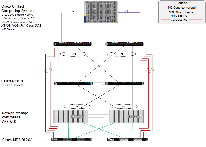
The reference hardware configuration includes:
● Cisco UCS 6536 Fabric Interconnects provides the chassis and network connectivity.
● The Cisco UCS X9508 Chassis connects to fabric interconnects using Cisco UCSX 9108-100G IFMs, where four 100 Gigabit Ethernet ports are used on each IFM to connect to the appropriate FI. If additional bandwidth is required, all eight 100G ports can be utilized. The Cisco UCSX 9108-25G IFMs can also be used with 4x25G breakout cables used to connect the chassis to the fabric interconnects.
● Cisco UCS X-series M7 Compute Nodes contain fifth-generation Cisco UCS 15231 virtual interface cards (VICs) which can be used with either IFM. Cisco UCS 15420 and 15422 VICs can also be used with either IFM.
● Cisco Nexus 93600CD-GX Switches in Cisco NX-OS mode provide the switching fabric.
● Cisco UCS 6536 Fabric Interconnect 100 Gigabit Ethernet uplink ports connect to Cisco Nexus 93600CD-GX Switches in a vPC configuration.
● The NetApp AFF A90 controllers connect to the Cisco Nexus 93600CD-GX Switches using two 100 GE ports from each controller configured as a vPC for NFS traffic.
● Cisco UCS 6536 Fabric Interconnects are connected to the Cisco MDS 9124V switches using multiple 32-Gbps Fibre Channel connections (utilizing breakouts) configured as a single port channel for SAN connectivity.
● The NetApp AFF A90 controllers connect to the Cisco MDS 9124V switches using 64-Gbps Fibre Channel connections for SAN connectivity.
● VMware 8.0 ESXi software is installed on Cisco UCS X-Series M7 Compute Nodes and servers to validate the infrastructure. For bare-metal scenarios SLES for SAP 15 SP6 and RHEL 9.4 for SAP are installed.
Note: In this FC-based storage access configuration, HANA data and log LUNs are served using FC and HANA shared LUNs with NFS.
SAP HANA TDI – Virtualized and Bare Metal Server Configuration
In this lab validation utilizing two Cisco UCS X210c M7 nodes and three Cisco UCS X410c M7 nodes, former was used for single-host configuration validation each in virtualized and bare metal scenario and latter, in a 2+1 multi-host bare metal configuration scenario validation.
The two socket X210c M7 compute nodes boot via iSCSI emulating the IP-only based setup and the four socket X410c M7 compute nodes boot from SAN via FC. From a networking perspective, 2-socket nodes used for virtualized and bare metal single-host system will have vNICs configured to be able to direct mount the HANA persistence data, log and shared volumes inside the HANA VM or bare metal node alike. The four socket nodes access HANA persistence data and log LUNs via FC and have vNIC configured to access/mount the HANA shared filesystem. Additionally, each node of the multi-host system will have a vNIC for internode communication.
VLAN Configuration
Table 1 lists VLANs configured for setting up the FlexPod environment along with their usage.
| ID |
Name |
Usage |
IP Subnet used in this deployment |
| 2*** |
Native-VLAN |
Use VLAN 2 as native VLAN instead of default VLAN (1). |
|
| 101 |
fcoe_vlan_a |
FCoE VLAN for MDS switch A Fibre Channel traffic |
|
| 102 |
fcoe_vlan_b |
FCoE VLAN for MDS switch B Fibre Channel traffic |
|
| 1130*** |
OOB-MGMT |
Out-of-band management VLAN to connect management ports for various devices. |
10.113.0.0/24; GW: 10.113.0.254 |
| 1131 |
IB-MGMT |
In-band management VLAN utilized for all in-band management connectivity - for example, Admin network for ESXi hosts, VM management, and so on. |
10.113.1.0/24; GW: 10.113.1254 |
| 1132 |
vMotion ** |
VMware vMotion traffic. |
10.113.2.0/24; GW: 10.113.2.254 |
| 1133 |
HANA-Appserver |
SAP Application server network. |
10.113.3.0/24 |
| 1134 |
HANA-Data |
SAP HANA Data NFS filesystem network for IP/NFS only solution. |
10.113.4.0/24 |
| 1135 |
Infra-NFS ** |
NFS VLAN for mounting datastores in ESXi servers for VM boot disks. |
10.113.5.0/24 |
| 1136 |
HANA-Log |
SAP HANA Log NFS filesystem network for IP/NFS only solution. |
10.113.6.0/24 |
| 1137 |
HANA-Shared |
SAP HANA shared filesystem network. |
10.113.7.0/24 |
| 1138* |
iSCSI-A |
iSCSI-A path for storage traffic including boot-from-san traffic. |
10.113.8.0/24 |
| 1139* |
iSCSI-B |
iSCSI-B path for storage traffic including boot-from-san traffic. |
10.113.9.0/24 |
| 76 |
HANA-Internode |
Node-to-Node communication in multi-host systems only. |
192.168.76.0/24 |
| 77 |
HANA-Backup |
SAP HANA node backup network |
192.168.77.0/24 |
* iSCSI VLANs are not required if using FC storage access.
**Only needed for Virtualized SAP HANA use cases.
***VLANs configured in FlexPod Base.
Table 2 lists the software revisions for various components of the solution.
| Component |
Software |
|
| Network |
Cisco Nexus 93600CD-GX |
10.4(5)M |
| Cisco MDS 9124V |
9.4(3a) |
|
| Compute |
Cisco UCS Fabric Interconnect 6536 and Cisco UCS 9108-100G IFM |
4.3(4.250004) |
| Cisco UCS X210C M7 / X410c M7 |
5.3(0.250001) |
|
| Storage |
NetApp AFF A90 |
ONTAP 9.16.1 |
| Software |
VMware ESXi |
8.0.3-24022510 |
| VMware vCenter Appliance |
8.0.3-24022515 |
|
| Cisco Intersight Assist Virtual Appliance |
1.0.11-202 |
|
| VMware ESXi nfnic FC Driver |
5.0.0.45 |
|
| VMware ESXi nenic Ethernet Driver |
2.0.15.0 |
|
| SLES for SAP |
15 SP6 |
|
| RHEL for SAP HANA |
9.4 |
|
| NetApp ONTAP tools for VMware vSphere |
10.3 |
|
| NetApp Active IQ Unified Manager |
9.16 |
|
| NetApp SnapCenter Plug-in for VMware vSphere |
6.1 |
|
| ONTAP Linux Host Utilities |
7.1 |
|
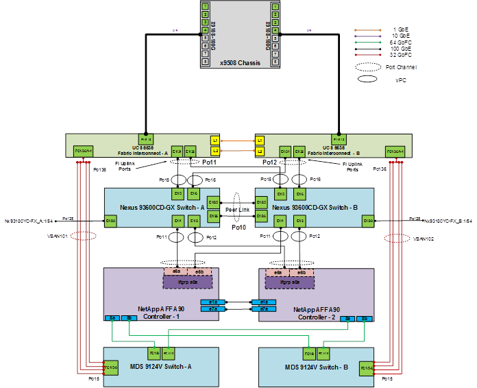
The information in this section is provided as a reference for cabling the physical equipment in a FlexPod environment. To simplify cabling requirements, a cabling diagram was used.
The cabling diagram in this section contains the details for the prescribed and supported configuration of the NetApp AFF A90 running NetApp ONTAP 9.16.1.
Note: For any modifications of this prescribed architecture, consult the NetApp Interoperability Matrix Tool (IMT).
Note: This document assumes that out-of-band management ports are plugged into an existing management infrastructure at the deployment site. These interfaces will be used in various configuration steps.
Note: Be sure to use the cabling directions in this section as a guide.
The NetApp storage controller and disk shelves should be connected according to best practices for the specific storage controller and disk shelves. For disk shelf cabling, refer to NetApp Support.
Figure 2 details the cable connections used in the validation lab for the FlexPod topology based on the Cisco UCS 6536 fabric interconnect. Two 100Gb links connect each Cisco UCS Fabric Interconnect to the Cisco Nexus Switches. Each NetApp AFF controller connects to the Cisco Nexus Switches for IP/NFS access and to Cisco MDS switches for FC based access to storage. Additional 1Gb management connections will be needed for one or more out-of-band network switches that sit apart from the FlexPod infrastructure. Each Cisco UCS fabric interconnect and Cisco Nexus switch is connected to the out-of-band network switches, and each AFF controller has a connection to the out-of-band network switches. Layer 3 network connectivity is required between the Out-of-Band (OOB) and In-Band (IB) Management Subnets.
FlexPod Base Configuration
The SAP HANA Tenant is intended to be built on top of FlexPod Base and can coexist with other tenants. If FlexPod Base has not been installed on FlexPod, see FlexPod Datacenter Base Configuration using IaC with Cisco IMM and NetApp ONTAP to install FlexPod Base. Note that the SAP HANA Tenant is primarily an FC based solution, but also utilizing NFS. When FlexPod Base is installed, use it to configure all the available FlexPod components.
One part of the FlexPod Base installation is installing an Ansible VM or machine that is used to run the Ansible playbooks. For FlexPod Base, in the ansible.cfg file in the user directory, “jinja2_native=True” was set. To run the FlexPod SAP HANA Tenant scripts, this parameter needs to be commented out as shown below:
cat ~/.ansible.cfg
[defaults]
interpreter_python=/usr/bin/python3.11
#jinja2_native=True
Clone the GitHub Repository
You need to use a GitHub repository from one public location; the first step in the process is to clone the GitHub collection named FlexPod-M7-SAPHANA (https://github.com/ucs-compute-solutions/FlexPod-M7-SAPHANA.git) to a new empty folder on the Ansible workstation. Cloning the repository creates a local copy, which is then used to run the playbooks that have been created for this solution.
1. From the Ansible workstation, change directories to the folder where the Ansible collections are located – something like /home/admin/ansible.
2. Clone the GitHub collection using the following command:
git clone https://github.com/ucs-compute-solutions/FlexPod-M7-SAPHANA.git
3. Change directories to the new folder named FlexPod-M7-SAPHANA.
Network Switch Configuration
This chapter contains the following:
● Cisco Nexus Switch Ansible Configuration
This chapter provides a detailed procedure for using an Ansible playbook to configure the Cisco Nexus 93600CD-GX switches for use in a FlexPod Datacenter for SAP HANA TDI environment.
The following procedures describe how to configure the Cisco Nexus switches for use in the SAP HANA TDI FlexPod environment.
The following procedure includes:
● Setup of NTP distribution on the IB-MGMT VLAN. The interface-vlan feature and ntp commands are used to set this up.
● Adding the tenant VLANs to the appropriate port-channels.
Cisco Nexus Switch Ansible Configuration
Procedure 1. Configure the Cisco Nexus switches from the Ansible workstation
Step 1. Add Nexus switch ssh keys to /home/admin/.ssh/known_hosts. Adjust known_hosts as necessary if errors occur:
ssh admin@<nexus-A-mgmt0-ip>
exit
ssh admin@<nexus-B-mgmt0-ip>
exit
Step 2. Edit the following variable files to ensure the proper Cisco Nexus variables are entered:
● FlexPod-M7-SAPHANA/group_vars/all.yml
● FlexPod-M7-SAPHANA /group_vars/secrets.yml
● FlexPod-M7-SAPHANA /group_vars/nexus.yml
● FlexPod-M7-SAPHANA /inventory
● FlexPod-M7-SAPHANA /host_vars/n9kA.yml
● FlexPod-M7-SAPHANA /host_vars/n9kB.yml
Note: Port-channel numbers in FlexPod-M7-SAPHANA/group_vars/nexus.yml should be the same as setup in FlexPod Base.
Step 3. From FlexPod-M7-SAPHANA, run the Setup_Nexus.yml Ansible playbook:
ansible-playbook ./Setup_Nexus.yml -i inventory
Step 4. Run the following commands to see the switch configuration and status:
show run
show vpc
show vlan
show port-channel summary
show ntp peer-status
show cdp neighbors
show lldp neighbors
show run int
show int
show udld neighbors
show int status
NetApp ONTAP Storage Configuration
This chapter contains the following:
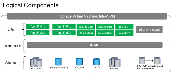
● NetApp ONTAP Storage Ansible Configuration – Infra-SVM Tenant: Part 1
This chapter provides a detailed procedure for using an Ansible playbook to configure the NetApp AFF A90 storage for use in a FlexPod with SAP HANA TDI environment.
Note: The following procedures describe how to configure the NetApp ONTAP storage for use in the SAP HANA TDI FlexPod environment. This procedure assumes the use of NetApp AFF A90 running ONTAP 9.16.1 software version.
The following procedure includes the following tasks:
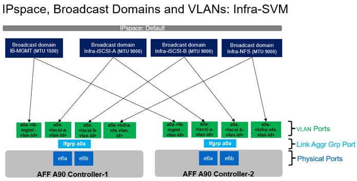
● Creation of dedicated IPspace for Infra tenant, followed by relevant broadcast-domains, VLANs, adding VLANs to corresponding broadcast-domains.
● Creating an SVM for Infra tenant and enabling the required services (FC, NFS and iSCSI) on the SVM.
● Creation of logical interfaces (LIFs) for storage access, required volumes and export policy for server boot infra setup.
NetApp ONTAP Storage Ansible Configuration – Infra-SVM Tenant: Part 1
Procedure 1. Configure the NetApp ONTAP Storage for the Infra Tenant
Step 1. Edit the following variable files to ensure the proper NetApp ONTAP storage variables are entered:
● FlexPod-M7-SAPHANA/group_vars/all.yml
● FlexPod-M7-SAPHANA /group_vars/secrets.yml
● FlexPod-M7-SAPHANA /group_vars/ontap
● FlexPod-M7-SAPHANA /inventory
● FlexPod-M7-SAPHANA /vars/ontap_main.yml
Step 2. From FlexPod-M7-SAPHANA, run the Setup_ONTAP.yml Ansible playbook with the associated tag for this section:
ansible-playbook ./Setup_ONTAP.yml -i inventory -t ontap_config_part1
Procedure 2. Update var files
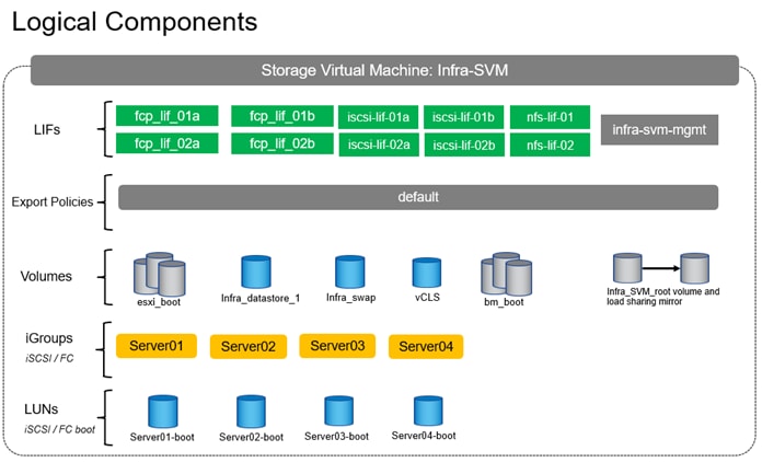
Step 1. Update the FlexPod-M7-SAPHANA/group_vars/all.yml file with iSCSI target IQN information from the array. The iSCSI target node part of the Infra-SVM could be checked on the ONTAP System Manager GUI by accessing the path: Storage > Storage VMs > Infra-SVM > Settings > Protocols > iSCSI. Alternatively, the same can be checked using ONTAP CLI “iscsi show -vserver Infra-SVM” command.
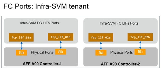
Step 2. Update the FlexPod-M7-SAPHANA/group_vars/all.yml file with FC LIFs target WWPN information from the array. Check the target WWPN of the FC LIFs part of the Infra-SVM on the ONTAP System Manager GUI by accessing the path: Storage > Storage VMs > Infra-SVM > Settings > Protocols > FC. Alternatively, the same can be checked using ONTAP CLI “fcp portname show -vserver Infra-SVM” command.
Cisco Intersight Managed Mode Configuration
This chapter contains the following:
● Set up Cisco Intersight Resource Group
● Set up Cisco Intersight Organization
● Add Intersight IMM Pools and SAP HANA specific VLANs
● Add Intersight IMM Server Policies
● Add Intersight IMM Server Profile Templates
● Add Intersight IMM Server Policies - Bare Metal specific
● Add Intersight IMM Server Profile Templates – Bare Metal specific
The Cisco Intersight platform is a management solution delivered as a service with embedded analytics for Cisco and third-party IT infrastructures. The Cisco Intersight Managed Mode (also referred to as Cisco IMM or Intersight Managed Mode) is an architecture that manages Cisco Unified Computing System (Cisco UCS) fabric interconnect–attached systems through a Redfish-based standard model. Cisco Intersight Managed Mode standardizes both policy and operation management for Cisco UCS X-Series M7 compute nodes used in this deployment guide.
Procedure 1. Set up Cisco Intersight Resource Group
Optionally, a Cisco Intersight resource group for the SAP HANA tenant can be created where resources will be logically grouped. In FlexPod Base, a Resource Group for the entire FlexPod was set up. In our lab example, we used the Default resource group available, but you can choose to create multiple resource groups for granular control of the resources.
To create a resource group for SAP HANA tenant:
Step 1. Log into Cisco Intersight.
Step 2. Select System.
Step 3. Click Resource Groups on the left.
Step 4. Click + Create Resource Group in the top-right corner.
Step 5. Provide a name for the Resource Group (for example, AC03-HANA-rg).
Step 6. Under Resources, select Custom.
Step 7. Select all resources that are connected to this SAP HANA FlexPod tenant.
Step 8. Click Create.
Procedure 2. Set up Cisco Intersight Organization
In this procedure, an Intersight organization for the SAP HANA tenant is created where all Cisco Intersight Managed Mode configurations including policies are defined. In FlexPod Base, we created an organization ‘AC03’.
Step 1. Log into the Cisco Intersight portal.
Step 2. Select System.
Step 3. Click Organizations on the left.
Step 4. Click + Create Organization in the top-right corner.
Step 5. Provide a name for the organization (for example, AC03-HANA). Optionally, select Share Resources with Other Organizations and click Next.
Step 6. Select the Resource Group created in the previous step (for example, AC03-HANA-rg) and click Next.
Step 7. Click Create.
Procedure 3. Add Intersight IMM Pools and SAP HANA specific VLANs
This procedure adds the necessary Intersight IMM Pools. It continues the UCS base configuration by adding SAP HANA specific VLANs to the Fabric Interconnects.
Step 1. Edit the following variable files to ensure proper Cisco Intersight IMM variables are entered:
● FlexPod-M7-SAPHANA/group_vars/all.yml
● FlexPod-M7-SAPHANA/group_vars/secrets.yml
● FlexPod-M7-SAPHANA/group_vars/ucs.yml
● FlexPod-M7-SAPHANA/SecretKey.txt
● FlexPod-M7-SAPHANA/roles/UCS-IMM/create_pools/defaults/main.yml
Step 2. From FlexPod-M7-SAPHANA, run the Setup_IMM_Pools.yml Ansible playbook:
ansible-playbook ./Setup_IMM_Pools.yml
Procedure 4. Add Intersight IMM Server Policies - virtualized host specific
Note: This procedure is valid for virtualized SAP HANA node preparation. For bare metal SAP HANA installations go to Procedure 6.
The Setup_IMM_Server_Policies.yml playbook is designed to run specifically for Intel CPU types and M7 server generations. It is important to run the Setup_IMM_Server_Policies.yml playbook and the Setup_IMM_Server_Profile_Templates.yml playbooks in succession.
Note: Importantly, the BIOS policy, boot policies based on iSCSI and FC and their associated network, QoS, adapter policies, LAN, and SAN connectivity policies specific to virtualized SAP HANA installation are defined in this procedure.
Step 1. Edit the following variable files to ensure the proper Cisco Intersight IMM variables are entered:
● FlexPod-M7-SAPHANA /group_vars/all.yml
● FlexPod-M7-SAPHANA /group_vars/secrets.yml
● FlexPod-M7-SAPHANA /group_vars/ucs.yml
● FlexPod-M7-SAPHANA /SecretKey.txt
● FlexPod-M7-SAPHANA /roles/UCS-IMM/create_server_policies/defaults/main.yml
Step 2. From FlexPod-M7-SAPHANA, run the Setup_IMM_Server_Policies.yml Ansible playbook:
ansible-playbook ./Setup_IMM_Server_Policies.yml
Procedure 5. Add Intersight IMM Server Profile Templates – virtualized host specific
Note: This follow-up procedure is valid for virtualized SAP HANA node preparation. For bare metal SAP HANA installations go to Procedure 6.
The Setup_IMM_Server_Profile_Templates.yml playbook is designed to be run immediately after the Setup_IMM_Server_Policies.yml playbook is run to create Server Profile Templates specific to iSCSI and/or FC booting virtualized SAP HANA nodes.
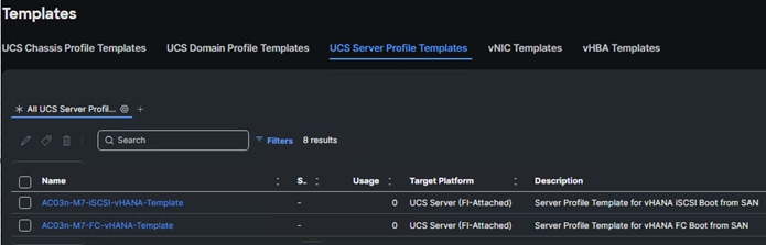
Note: Prefix AC03n was used in the validation setup.
Step 1. Edit the following variable files to ensure proper Cisco Intersight IMM variables are entered:
● FlexPod-M7-SAPHANA/group_vars/all.yml
● FlexPod-M7-SAPHANA/group_vars/secrets.yml
● FlexPod-M7-SAPHANA/group_vars/ucs.yml
● FlexPod-M7-SAPHANA/SecretKey.txt
● FlexPod-M7-SAPHANA/roles/UCS-IMM/create_server_profile_template/defaults/main.yml
Step 2. From FlexPod-M7-SAPHANA, run the Setup_IMM_Server_Profile_Templates.yml Ansible playbook:
ansible-playbook ./Setup_IMM_Server_Profile_Templates.yml
Note: The server profile templates created above assume that each HANA node does boot locally using iSCSI or FC from SAN (NetApp Array).
Procedure 6. Add Intersight IMM Server Policies - Bare Metal specific
Note: This procedure is valid for bare metal based SAP HANA node preparation. Skip this step if implementing virtualized SAP HANA.
The Setup_IMM_Server_Policies_Baremetal.yml playbook is designed to address bare metal SAP HANA installations.
BIOS policy, LAN connectivity policies addressing both single-host and multi-host implementations with their associated adapter policies, network group policies, QoS policy, vNIC templates specific to bare metal scenario are created in this step.
Note: It is important to run the Setup_IMM_Server_Policies_Baremetal.yml playbook and the Setup_IMM_Server_Profile_Templates_Baremetal.yml playbooks in succession.
Step 1. Edit the following variable files to ensure the proper Cisco Intersight IMM variables are entered:
● FlexPod-M7-SAPHANA/group_vars/all.yml
● FlexPod-M7-SAPHANA/group_vars/secrets.yml
● FlexPod-M7-SAPHANA/group_vars/ucs.yml
● FlexPod-M7-SAPHANA/SecretKey.txt
● FlexPod-IMM- SAPHANA/roles/UCS-IMM/create_baremetal_server_policies/defaults/main.yml
Step 2. From FlexPod-M7-SAPHANA, run the Setup_IMM_Server_Policies_Baremetal.yml Ansible playbook:
ansible-playbook ./Setup_IMM_Server_Policies_Baremetal.yml
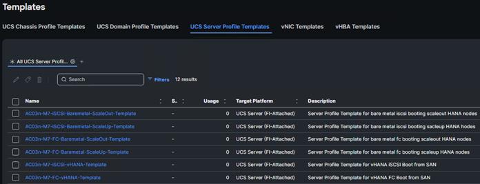
Procedure 7. Add Intersight IMM Server Profile Templates - Bare Metal specific
Note: This follow-up procedure is valid for bare metal based SAP HANA node preparation. Skip this step if implementing virtualized SAP HANA.
The Setup_IMM_Server_Profile_Templates_Baremetal.yml playbook is designed to be run immediately after the Setup_IMM_Server_Policies_Baremetal.yml playbook is run to create Server Profile Templates addressing bare metal installation of either iSCSI or FC booting, single-host, or multi-host type HANA nodes.
Step 1. Edit the following variable files to ensure the proper Cisco Intersight IMM variables are entered:
● FlexPod-M7-SAPHANA/group_vars/all.yml
● FlexPod-M7-SAPHANA/group_vars/secrets.yml
● FlexPod-M7-SAPHANA/group_vars/ucs.yml
● FlexPod-M7-SAPHANA/SecretKey.txt
● FlexPod-M7-SAPHANA/roles/UCS-IMM/create_baremetal_server_profile_template/defaults/main.yml
Step 2. From FlexPod-M7-SAPHANA, run the Setup_IMM_Server_Profile_Templates_Baremetal.yml Ansible playbook:
ansible-playbook ./Setup_IMM_Server_Profile_Templates_Baremetal.yml
Note: The server profile templates created above assume that each HANA node does boot locally using iSCSI or FC from SAN (NetApp Array).
Procedure 8. Derive Server Profiles
While the created service profile templates address all the possible combinations of booting type (iSCSI or FC) with scaling mode of HANA system [single-host or multi-host], two prominent use cases – FC booting bare metal SAP HANA system and iSCSI booting scale-up virtual HANA system are detailed in this document.
The validation setup has Cisco UCS 9508 chassis populated with 3 x UCS X410c M7 and 2 x UCS X210 M7 compute nodes. A FC booting bare-metal multi-host 2+1 SAP HANA system with 3 UCS X410c M7 nodes and an iSCSI booting single-host (VM) virtualized SAP HANA system with a UCS X210c M7 preparation will be detailed here.
Step 1. Go to the Configure > Templates page, to the right of the AC03n-M7-baremetal-FC-scaleout-SPT, click … and select Derive Profiles.
Step 2. Under the Server Assignment, select Assign Now and select the three Cisco UCS X410c M7 servers that will be for the 2+1 scale-out SAP HANA system.
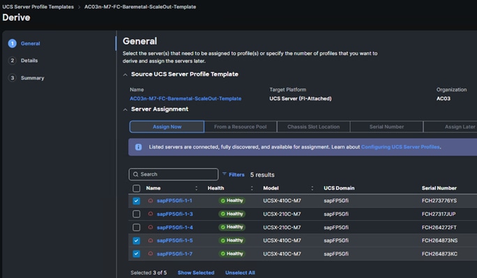
Step 3. Click Next.
The three server names correspond to the SAP HANA multi-host node hostnames as shown below:
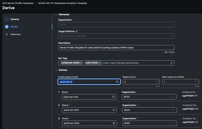
Step 4. Click Next.
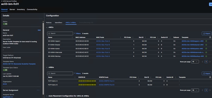
Step 5. Click Derive to derive the SAP HANA Scale-out Node Server Profiles.
Step 6. Select Profiles on the left and then select the UCS Server Profiles tab. Take note of the host WWPN assigned to each of the nodes of the SAP HANA Scale-out system.
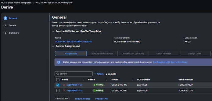
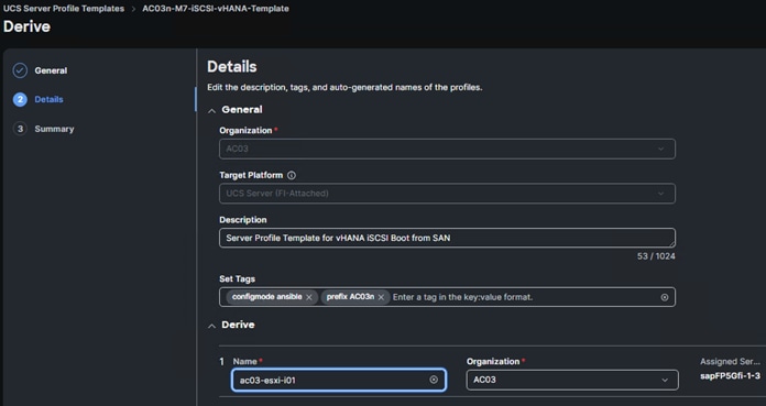
Step 7. Repeat this process to create an iSCSI boot virtualized SAP HANA Profile using the AC03n-M7-iSCSI-vHANA-Template.
Step 8. Select the iSCSI boot virtualized SAP HANA Node profile and then click the … at the top or bottom of the list and select Deploy.
Step 9. Select Reboot Immediately to Activate and click Deploy.
Note: Post deployment takes note of the host IQN information.
When the server profiles are assigned to the nodes, do the following:
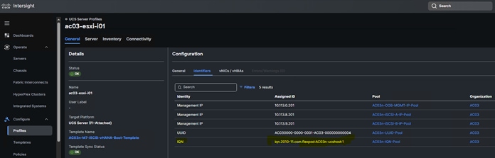
Step 1. Update the FlexPod-M7-SAPHANA/group_vars/all.yml file with iSCSI initiator IQN information from the Intersight > Profile > <server-profile> General > Configuration > Identifiers tab.
Step 2. Update the FlexPod-M7-SAPHANA/group_vars/all.yml file with FC hosts initiator WWPN information from the server profiles: Intersight > Profile > <server-profile> General > Configuration > vNICs/vHBAs tab.
SAN Switch Configuration
This chapter contains the following:
● FlexPod Cisco MDS Switch Ansible Config - Infra Tenant
This chapter explains how to configure the Cisco MDS 9000s to support the Infra tenant. The configuration covered in this section is only needed when configuring Fibre Channel storage access.
This chapter addresses the following tasks:
● Enables and verifies features, DNS and NTP configs, interface-port channel, and trunk settings.
● Configures VSAN, device-aliases, zones, and activates the zoneset.
FlexPod Cisco MDS Switch Ansible Config - Infra Tenant
The following procedure describes how to configure the Cisco MDS switches for use in an SAP HANA TDI based FlexPod environment.
Procedure 1. FlexPod Cisco MDS Switch Ansible Configuration
Step 1. Add MDS switch ssh keys to /home/admin/.ssh/known_hosts. Adjust known_hosts as necessary if errors occur:
ssh admin@<mds-A-mgmt0-ip>
exit
ssh admin@<mds-B-mgmt0-ip>
exit
Step 2. Edit the following variable files to ensure proper MDS variables are entered:
FlexPod-M7-SAPHANA/group_vars/secrets.yml
FlexPod-M7-SAPHANA/inventory
FlexPod-M7-SAPHANA/group_vars/all.yml
FlexPod-M7-SAPHANA/host_vars/mdsA.yml
FlexPod-M7-SAPHANA/host_vars/mdsB.yml
FlexPod-M7-SAPHANA/roles/MDSconfig/defaults/main.yml
Note: The WWPN information of FC LIFs should have already been entered into the all.yml file so that the UCS IMM Boot Order Policies could be built. The Cisco UCS server initiator WWPNs for FC should also be entered into all.yml. To query these WWPNs, log into Cisco Intersight and select each of the FC boot based Server Profiles by accessing: Intersight - > Profile -> <server-profile> General -> Configuration -> vNICs/vHBAs tab.
Step 3. From FlexPod-M7-SAPHANA, run the Setup_MDS.yml Ansible playbook:
ansible-playbook ./Setup_MDS.yml -i inventory
Note: Smart licensing should be set up in the MDS switches. For more information see: Cisco MDS 9000 Series Licensing Guide, Release 9.x.
Step 4. Run the following commands to see the switch configuration and status:
show interface brief
show port-channel summary
show vsan membership
sh device-alias database
show zone
sh zoneset active
Storage Configuration – ONTAP Boot Storage Setup
This chapter contains the following:
● Ansible ONTAP Storage Configuration – Infra-SVM Tenant: Part 2
This configuration requires information from the Cisco UCS server profiles and NetApp storage system. The procedures in this section address: creating the boot LUNs, initiator groups, and appropriate mappings between the two. With appropriate zoning config in place, Cisco UCS server profiles will be able to see the boot disks hosted on NetApp storage controllers.
Ansible ONTAP Storage Configuration – Infra-SVM Tenant: Part 2
Procedure 1. Obtain the WWPNs for UCS Server Profiles (required only for FC configuration)
Note: This procedure was completed here: Procedure 9: Update var files.
Procedure 2. Obtain the IQNs for UCS Server Profiles (required only for iSCSI configuration)
Step 1. From the UCS Intersight account page, go to Infrastructure Service > Configure > Profiles > UCS Server Profiles > Profile > General > Configuration > Identifiers. The required IQN can be found to the right of IQN.
Note: This step is also explained here: Procedure 9: Update var files.
Procedure 3. Configure ONTAP Boot Storage using Ansible
Step 1. Edit the following variable files to ensure the proper ONTAP Boot Storage variables are entered:
● FlexPod-M7-SAPHANA/group_vars/all.yml
● FlexPod-M7-SAPHANA/vars/ontap_main.yml
Step 2. Update the boot_luns_iscsi and boot_luns_fcp variables under the vars/ontap_main.yml file for iSCSI and FCP boot storage configuration of virtualized/ESXi nodes and the boot_luns_iscsi_bm and boot_luns_fcp_bm variables for iSCSI and FCP boot storage configuration of bare metal nodes. Update the initiator IQNs and WWPNs related variables in group_vars/all.yml file. Initiator IQNs and WWPNs are needed for iSCSI and FCP igroups configurations, respectively.
Step 3. From FlexPod-M7-SAPHANA, invoke the ansible scripts for this section using the following command:
ansible-playbook -i inventory Setup_ONTAP.yml -t ontap_config_part_2
Storage Configuration – Finalize ONTAP Storage
This chapter contains the following:
● Ansible ONTAP Storage Configuration – Infra-SVM Tenant: Part 3
Ansible ONTAP Storage Configuration – Infra-SVM Tenant: Part 3
Procedure 1. Finalize ONTAP storage using Ansible
Step 1. Edit the following variable files to ensure the proper variables are entered:
● FlexPod-M7-SAPHANA/group_vars/all.yml
● FlexPod-M7-SAPHANA/vars/ontap_main.yml
Step 2. From FlexPod-M7-SAPHANA, invoke the ansible scripts for this section using the following command:
ansible-playbook -i inventory Setup_ONTAP.yml -t ontap_config_part_3
Prepare VMware ESXi host for SAP HANA
This chapter contains the following:
● Download ESXi 8.0U3 from VMware
● Cisco Intersight-based VMware ESXi 8.0U3 Install: Method 1
● Cisco Intersight KVM Manual Installation: Method 2
● Cisco Intersight Hardware Compatibility List (HCL) Status
● FlexPod VMware ESXi Ansible Configuration
● vCenter and ESXi Ansible Setup
● Configure vSphere Cluster Services
● vSphere Clustering Service Deployment Guidelines for SAP HANA Landscapes
● Enable EVC on the VMware Cluster
This chapter is for the virtualized SAP HANA use case. For Bare Metal implementation, go to Prepare Bare Metal Host for SAP HANA.
This section provides detailed instructions for installing VMware ESXi 8.0U3 in case of virtualized SAP HANA implementation. On successful completion of these procedures, multiple ESXi hosts will be provisioned and ready to be added to VMware vCenter.
Several methods exist for installing ESXi in a VMware environment. These procedures focus on how to use the built-in keyboard, video, mouse (KVM) console and virtual media features in Cisco Intersight to map remote installation media to individual servers.
Download ESXi 8.0U3 from VMware
Procedure 1. Download VMware ESXi ISO
Step 1. Click the following link: Cisco Custom Image for ESXi 8.0U3 Install CD.
Note: You will need a VMware user id and password on vmware.com to download this software.
Step 2. Download the .iso file.
Cisco Intersight-based VMware ESXi 8.0U3 Install: Method 1
VMware ESXi 8.0U3 can be installed and initially configured using Cisco Intersight. This feature requires the Intersight Advantage license to be installed and in use. The Intersight-based OS install makes use of the latest release of the Cisco UCS Server Configuration Utility (SCU).
Procedure 1. Download Cisco UCS SCU and prepare software repository
Step 1. Click the following link: Cisco UCS SCU 7.1.
Note: You will need a Cisco id and password to download this software.
Step 2. Download the .iso file.
Step 3. Place both the downloaded SCU ISO and the downloaded Cisco Custom Image for ESXi 8.0U3 ISO previously downloaded on an https server.
Note: It is critical that these files are placed on an https (not http) server for the OS installation to complete. These files can also be placed on a CIFS or NFS server if that is more convenient. This procedure assumes use of https, but CIFS or NFS are supported and can also be used.
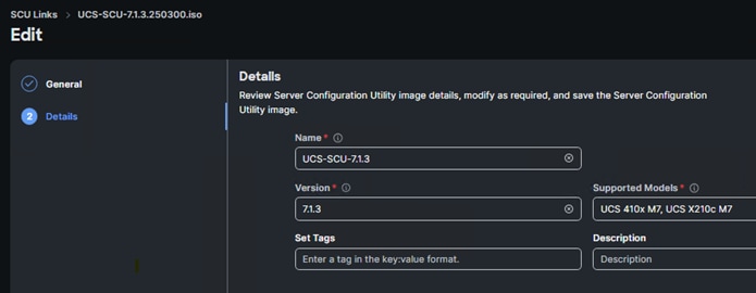
Step 4. In Cisco Intersight, go to System > Software Repository > SCU Links and click Add SCU Link.
Step 5. Select the correct Organization (for example, AC03) and HTTP/S. Input the File Location URL using https://. Click Next.
Step 6. Provide a Name for the SCU link (for example, UCS-SCU-7.1.3), a Version (for example,7.1.3, and Supported Models (for example, ALL). Click Add.
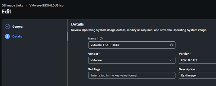
Step 7. In Cisco Intersight, go to System > Software Repository > OS Image Links and click Add OS Image Link.
Step 8. Select the correct Organization (for example, AC03) and HTTP/S. Input the File Location URL using https://. Click Next.
Step 9. Provide a Name for the OS Image link (for example, ESXi 8.0U3 Cisco Custom), a Vendor (for example, VMware), and a Version (for example, ESXi 8.0U3). Click Add.
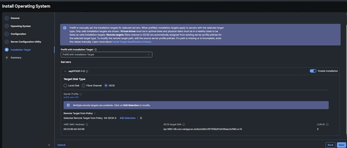
Procedure 2. Install Operating System – VMWare ESXi 8.0 U3
Step 1. In Cisco Intersight, go to Operate > Servers. Check the box next to each server that will have VMware ESXi 8.0U3 installed. Click … and select Install Operating System.
Step 2. Under General, the servers should already be selected. Check the boxes to install ESXi 8.0U3 on other servers. Click Next.
Step 3. Select the radio button for the ESXi 8.0U3 Cisco Custom OS Image Link previously added. Click Next.
Step 4. Leave Cisco selected as the Configuration Source. For each server, fill in all required fields. Click Next.
Note: Since the IB-MGMT VLAN was configured as the native VLAN for the vSwitch0 vNICs, it is not necessary to fill in a VLAN ID.
Step 5. Click Continue on the warning about Secure Boot.
Step 6. Select the radio button for the SCU Link previously added. Click Next.
Step 7. For each server, select the boot protocol (Fibre Channel or iSCSI), then fill in the appropriate information, including LUN ID 0. Click Next.
Note: For Fibre Channel boot, the Initiator WWPN can be obtained by opening a duplicate tab of the web browser window for Intersight and selecting Servers. Click the Server Name link. Click Inventory > Network Adapters > <Adapter> > Interfaces > vHBA Interfaces. Copy the WWPN to the right of FCP-Fabric-A. The Target WWPN can be obtained by connecting to the storage cluster with ssh and typing network interface show -vserver <Infra-SVM name>. Copy the WWPN for LIF fcp-lif-01a.
Note: For iSCSI boot, the VNIC MAC address can be obtained by opening a duplicate tab of the web browser window for Intersight and selecting Servers. Click the Server Name link. Click Inventory > Network Adapters > <Adapter> > Interfaces > NIC Interfaces. Copy the MAC Address to the right of 04-iSCSI-A. The iSCSI Target IQN can be obtained by connecting to the storage cluster with ssh and typing “iscsi show -vserver <Infra-SVM name>.
Step 8. Review all of the relevant information and click Install then click Install again to begin the OS Installation. The installation can take up to 45 minutes. The installation can be monitored using the Requests pane.
Cisco Intersight KVM Manual Installation: Method 2
If Intersight Managed OS installation is not used, the Cisco Intersight vKVM enables the administrators to begin the installation of the operating system (OS) through a vMedia connection to the Cisco Custom ISO.
Procedure 1. Log into Intersight and Launch KVM
In this procedure, the KVM-mapped Cisco Custom ISO can be used to mount the Cisco Custom ISO and install VMware ESXi.
Step 1. Log into Cisco Intersight.
Step 2. Go to Infrastructure Service > Servers > <Server>.
Step 3. Click the … to the right of the server and select Launch vKVM. Click Load KVM Certificate. Navigate the security prompts to launch the console.
Step 4. Launch vKVM consoles for all servers being provisioned.
Step 5. In each vKVM console, select Virtual Media > vKVM-Mapped DVD. Click Browse and browse to the downloaded VMware ESXi 8.0U3 Cisco Custom ISO. Click Open. Click Map Drive.
Step 6. In each vKVM console, go to Power > Reset System and click Confirm.
Procedure 2. Prepare the Server for the OS Installation
Note: Follow this step on each ESXi host.
Step 1. Monitor the server boot process in the vKVM. The server should find the boot LUNs and begin to load the ESXi installer.
Step 2. If the ESXi installer fails to load because the software certificates cannot be validated, reset the server, and when prompted, press F2 to go into BIOS and set the system time and date to current. The ESXi installer should load properly.
Procedure 3. Install VMware ESXi onto the bootable LUN of the UCS Servers
Note: Follow these steps on each host.
Step 1. After the ESXi installer is finished loading (from the last step), press Enter to continue with the installation.
Step 2. Read and accept the end-user license agreement (EULA). Press F11 to accept and continue.
Step 3. It may be necessary to map function keys as User Defined Macros under the Macros menu in the KVM console.
Step 4. Select the NetApp boot LUN that was previously set up as the installation disk for ESXi and press Enter to continue with the installation.
Step 5. Select the appropriate keyboard layout and press Enter.
Step 6. Enter and confirm the root password and press Enter.
Step 7. The installer issues a warning that the selected disk will be repartitioned. Press F11 to continue with the installation.
Step 8. After the installation is complete, press Enter to reboot the server.
Procedure 4. Add the Management Network for each VMware Host
Note: This is required for managing the host. To configure ESXi host with access to the management network, follow these steps on each ESXi host.
Step 1. After the server has finished rebooting, in the UCS KVM console, press F2 to customize VMware ESXi.
Step 2. Log in as root, enter the password set during installation, and press Enter to log in.
Step 3. Use the down arrow key to select Troubleshooting Options and press Enter.
Step 4. Select Enable ESXi Shell and press Enter.
Step 5. Select Enable SSH and press Enter.
Step 6. Press Esc to exit the Troubleshooting Options menu.
Step 7. Select the Configure Management Network option and press Enter.
Step 8. Select Network Adapters and press Enter. Ensure the vmnic numbers align with the numbers under the Hardware Label (for example, vmnic0 and 00-vSwitch0-A). If these numbers do not align, note which vmnics are assigned to which vNICs (indicated under Hardware Label).
Note: It is important not to select vmnic1 at this stage. If using the Ansible configuration and vmnic1 is selected here [for redundancy’s sake], the Ansible playbook will fail.
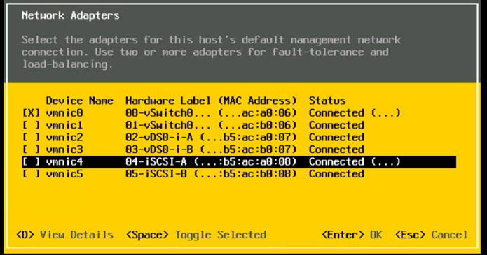
Step 9. Press Enter.
Note: In the UCS Configuration portion of this document, the IB-MGMT VLAN was set as the native VLAN on the 00-vSwitch0-A and 01-vSwitch0-B vNICs. Because of this, the IB-MGMT VLAN should not be set here and should remain Not set.
Step 10. Select IPv4 Configuration and press Enter.
Note: When using DHCP to set the ESXi host networking configuration, setting up a manual IP address is not required.
Step 11. Select the Set static IPv4 address and network configuration option by using the arrow keys and space bar.
Step 12. Under IPv4 Address, enter the IP address for managing the ESXi host.
Step 13. Under Subnet Mask, enter the subnet mask.
Step 14. Under Default Gateway, enter the default gateway.
Step 15. Press Enter to accept the changes to the IP configuration.
Note: Ansible scripts will disable IPv6.
Step 16. Select the DNS Configuration option and press Enter.
Note: If the IP address is configured manually, the DNS information must be provided.
Step 17. Using the spacebar, select the following DNS server addresses and hostname.
a. Under Primary DNS Server, enter the IP address of the primary DNS server.
b. Optional: Under Alternate DNS Server, enter the IP address of the secondary DNS server.
c. Under Hostname, enter the fully qualified domain name (FQDN) for the ESXi host.
Step 18. Press Enter to accept the changes to the DNS configuration.
Step 19. Press Esc to exit the Configure Management Network submenu.
Step 20. Press Y to confirm the changes and restart the management network.
Step 21. Back in the System Customization menu, use the arrow keys to select Test Management Network and press Enter.
Step 22. Press Enter to run the test.
Step 23. It is normal the first time the test is run for the first ping to fail. The test can be run again to see all fields pass, or if the remaining fields pass, press Enter.
Step 24. Press Esc to exit the System Customization menu.
Step 25. Repeat this procedure for all installed ESXi hosts.
Cisco Intersight Hardware Compatibility List (HCL) Status
Cisco Intersight evaluates the compatibility of your UCS system to check if the hardware and software have been tested and validated by Cisco or Cisco partners. Intersight reports validation issues after checking the compatibility of the server model, processor, firmware, adapters, operating system, and drivers, and displays the compliance status with the Hardware Compatibility List (HCL).
To determine HCL compatibility for VMware ESXi, Cisco Intersight uses Cisco UCS Tools. The Cisco UCS Tools is part of VMware ESXi Cisco custom ISO, and no additional configuration is required.
For more details on Cisco UCS Tools manual deployment and troubleshooting, go to: https://intersight.com/help/saas/resources/cisco_ucs_tools#about_cisco_ucs_tools
Procedure 1. View Compute Node Hardware Compatibility
Step 1. To find detailed information about the hardware compatibility of a Compute node, in Cisco Intersight, click Infrastructure Service > Operate > Servers and click a server and select HCL.
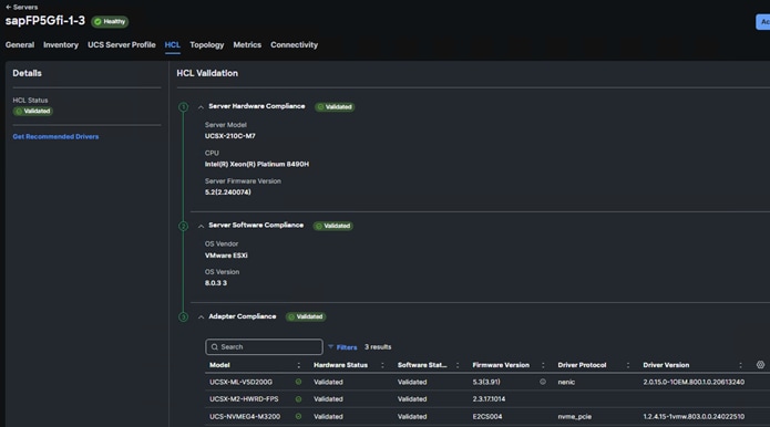
Note: If any of the drivers do not show Validated under Software Status, use this information to properly fill in the FlexPod-M7-SAPHANA/roles/VMware/ESXIhosts/defaults/main.yml file.
FlexPod VMware ESXi Ansible Configuration
Procedure 1. Use Ansible to Configure All VMware ESXi Hosts from the Management Workstation
In this procedure, the installed ESXI nodes are configured for NTP and DNS, IPv6 is disabled, vSwitch0 is modified by adding a redundant NIC followed by MTU setting to 9000, add application (SAP HANA specific) port group configurations, NFS VMK adapter, connecting to Infra-NFS datastore to enable carving VM boot volumes at a later stage.
Regarding the iSCSI booting ESXi nodes, additional steps to create the iSCSI port group configurations and adding all iSCSI targets to enable multipath are executed.
Step 1. Edit the following variable files to ensure proper VMware variables are entered:
● FlexPod-M7-SAPHANA/group_vars/secrets.yml
● FlexPod-M7-SAPHANA/inventory
● FlexPod-M7-SAPHANA/group_vars/all.yml
● FlexPod-M7-SAPHANA/roles/VMware/ESXIhosts/defaults/main.yml
● FlexPod-M7-SAPHANA/roles/VMware/ESXIiscsi/defaults/main.yml (If using iSCSI boot)
Step 2. From FlexPod-M7-SAPHANA, run the Setup_ESXi.yml Ansible playbook:
ansible-playbook ./Setup_ESXi.yml -i inventory
The procedures in the following sections provide detailed instructions for installing the VMware vCenter 8.0U3 Server Appliance in a FlexPod environment.
Procedure 1. Download vCenter 8.0U3 from VMware
Step 1. Click this link: VMware vCenter Server Appliance 8.0U3 and download the VMware-VCSA-all-8.0.3-24022515.iso.
Procedure 2. Install the VMware vCenter Server Appliance
The VCSA deployment consists of 2 stages: installation and configuration.
Step 1. Locate and copy the VMware-VCSA-all-8.0.3-24022515.iso file to the desktop of the management workstation. This ISO is for the VMware vSphere 8.0U3 vCenter Server Appliance.
Step 2. Mount the ISO image as a disk on the management workstation. For example, with the Mount command in Windows Server 2012 and above.
Step 3. In the mounted disk directory, go to the vcsa-ui-installer > win32 directory and double-click installer.exe. The vCenter Server Appliance Installer wizard appears.
Step 4. Click Install to start the vCenter Server Appliance deployment wizard.
Step 5. Click NEXT in the Introduction section.
Step 6. Read and accept the license agreement and click NEXT.
Step 7. In the vCenter Server Deployment Target window, enter the FQDN or IP address of the destination host, Username (root) and Password. Click NEXT.
Note: Installation of vCenter on a separate existing management infrastructure vCenter is recommended. If a separate management infrastructure is not available, customers can choose the recently configured first ESXi host as an installation target. The recently configured ESXi host is used in this deployment.
Step 8. Click YES to accept the certificate.
Step 9. Enter the Appliance VM name and password details shown in the Set up vCenter Server VM section. Click NEXT.
Step 10. In the Select Deployment Size section, select the Deployment size and Storage size. For example, select “Tiny” and “Default.” Click NEXT.
Step 11. Select the datastore (for example, infra_datastore) for storage. Click NEXT.
Step 12. In the Network Settings section, configure the following settings:
a. Select a Network: (for example, IB-MGMT Network)
Note: When the vCenter is running on the FlexPod, it is important that the vCenter VM stays on the IB-MGMT Network on vSwitch0 and is not moved to a vDS. If vCenter is moved to a vDS and the virtual environment is completely shut down and then brought back up, trying to bring up vCenter on a different host than the one it was running on before the shutdown will cause problems with the network connectivity. With the vDS, for a virtual machine to move from one host to another, vCenter must be up and running to coordinate the move of the virtual ports on the vDS. If vCenter is down, the port move on the vDS cannot occur correctly. Moving vCenter to a different host on vSwitch0 does not require vCenter to already be up and running. If this vCenter is running in a different management environment, it is fine to have its’ networking on a vDS.
b. IP version: IPV4
c. IP assignment: static
d. FQDN: <vcenter-fqdn>
e. IP address: <vcenter-ip>
f. Subnet mask or prefix length: <vcenter-subnet-mask>
g. Default gateway: <vcenter-gateway>
h. DNS Servers: <dns-server1>,<dns-server2>
Step 13. Click NEXT.
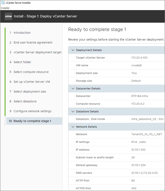
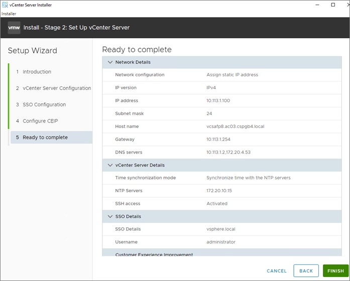
Step 14. Review all values and click FINISH to complete the installation.
Note: The vCenter Server appliance installation will take a few minutes to complete.
Step 15. When Stage 1, Deploy vCenter Server, is complete, click CONTINUE to proceed with stage 2.
Step 16. Click NEXT.
Step 17. In the vCenter Server Configuration window, configure these settings:
a. Time Synchronization Mode: Synchronize time with NTP servers.
b. NTP Servers: NTP server IP addresses from IB-MGMT VLAN
c. SSH access: Activated.
Step 18. Click NEXT.
Step 19. Complete the SSO configuration as shown below (or according to your organization’s security policies):
Step 20. Click NEXT.
Step 21. Decide whether to join VMware’s Customer Experience Improvement Program (CEIP).
Step 22. Click NEXT.
Step 23. Review the configuration and click FINISH.
Step 24. Click OK.
Note: vCenter Server setup will take a few minutes to complete and Install – Stage 2 with show Complete.
Step 25. Click CLOSE. Eject or unmount the VCSA installer ISO.
Procedure 3. Verify vCenter CPU Settings
Note: If a vCenter deployment size of Small or larger was selected in the vCenter setup, it is possible that the VCSA’s CPU setup does not match the Cisco UCS server CPU hardware configuration.
Step 1. Open a web browser on the management workstation and navigate to the vCenter or ESXi server where the vCenter appliance was deployed and login.
Step 2. Click the vCenter VM, right-click and select Edit settings.
Step 3. In the Edit settings window, expand CPU and check the value of Sockets.
Step 4. If the number of Sockets matches the server configuration, click Cancel.
Step 5. If the number of Sockets does not match the server configuration, it will need to be adjusted:
a. Right-click the vCenter VM and click Guest OS > Shut down. Click Yes on the confirmation.
b. When vCenter is shut down, right-click the vCenter VM and click Edit settings.
c. In the Edit settings window, expand CPU and change the Cores per Socket value to make the Sockets value equal to the server configuration.
Step 6. Click SAVE.
Step 7. Right-click the vCenter VM and click Power > Power on. Wait approximately 10 minutes for vCenter to come up.
Procedure 4. Setup VMware vCenter Server
Step 1. Using a web browser, go to https://<vcenter-ip-address>:5480. Navigate the security screens.
Step 2. Log into the VMware vCenter Server Management interface as root with the root password set in the vCenter installation.
Step 3. In the menu on the left, click Time.
Step 4. Click EDIT to the right of Time zone.
Step 5. Select the appropriate Time zone and click SAVE.
Step 6. In the menu on the left select Administration.
Step 7. According to your Security Policy, adjust the settings for the root user and password.
Step 8. In the menu on the left click Update.
Step 9. Follow the prompts to stage and install any available vCenter 8.0U3 updates.
Step 10. In the upper right-hand corner of the screen, click root > Logout to logout of the Appliance Management interface.
Step 11. Using a web browser, go to https://<vcenter-fqdn> and navigate through security screens.
Note: With VMware vCenter 7.0 and above, you must use the vCenter FQDN.
Step 12. Select LAUNCH VSPHERE CLIENT.
Step 13. Log in using the Single Sign-On username (administrator@vsphere.local) and password created during the vCenter installation. Dismiss the Licensing warning.
vCenter and ESXi Ansible Setup
Procedure 1. Configure the VMware vCenter and add ESXi hosts to be managed
In this procedure, the base installation is extended with creating a Datacenter object, followed by cluster for provisioned hosts and enabling HA/DRS. Distributed switch is created and need infra/application specific port groups are created.
Step 1. Edit the following variable files to ensure the proper VMware variables are entered:
● FlexPod-M7-SAPHANA/group_vars/secrets.yml
● FlexPod-M7-SAPHANA/inventory
● FlexPod-M7-SAPHANA/group_vars/all.yml
● FlexPod-M7-SAPHANA/roles/VMware/ESXIpostvC/defaults/main.yml
● FlexPod-M7-SAPHANA/roles/VMware/ESXIpostvCiscsi/defaults/main.yml
Step 2. From FlexPod-M7-SAPHANA, run the Setup_vCenter.yml Ansible playbook:
ansible-playbook ./Setup_vCenter.yml -i inventory
After the playbook run is complete, complete the following manual steps to complete vCenter setup.
Step 3. Right-click the Cluster that was created and select Settings.
Step 4. In the list in the center pane under Configuration, select General.
Step 5. On the right, to the right of General, select EDIT.
Step 6. Select Datastore specified by host and click OK.
Step 7. In the list on the left, select the first ESXi host. In the center pane, select the Configure tab.
Step 8. In the center pane list under Virtual Machines, click Swap File location.
Step 9. On the right, click EDIT.
Step 10. Select infra_swap and click OK.
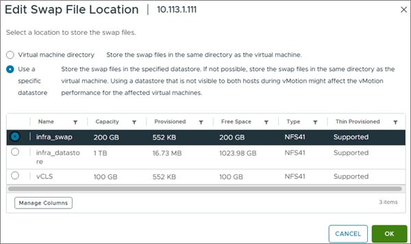
Step 11. Repeat steps 7-10 to set the swap file location for each ESXi host.
Step 12. Select each ESXi host and from the Summary tab, clear any alerts or alarms associated with the host.
Configure vSphere Cluster Services
The vSphere Cluster Services (vCLS) is a new feature introduced with vSphere 7 U1. It ensures cluster services such as vSphere DRS and vSphere HA are available to maintain the resources and health of the workloads like SAP HANA running in the cluster independent of the vCenter Server instance availability.
The vSphere Clustering service uses agent VMs to maintain cluster services health and up to three VMs are created when adding hosts to the cluster.
vSphere Clustering Service Deployment Guidelines for SAP HANA Landscapes
As of SAP Note 3372365 and subsequent guidelines per SAP HANA on vSphere 7 Update 1 – vSphere Cluster Service (vCLS), SAP HANA production VMs should not get co-deployed with any other workload VMs on the same vSphere ESXi host and NUMA node sharing between SAP HANA and non-HANA is not allowed. Because of these guidelines and due to the mandatory and automated installation process of vSphere Clustering Service, it is required to ensure vCLS VMs will get migrated to hosts that do not run SAP HANA production-level VMs.
This can be achieved by configuring a vSphere Clustering Service VM anti-affinity policy. This policy describes a relationship between VMs that have been assigned a special anti-affinity tag (for example a tag named SAP HANA) and vSphere Clustering service system VMs.
If this tag is assigned to SAP HANA VMs, the policy discourages placement of vSphere Clustering Service VMs and SAP HANA VMs on the same host. This ensures that vSphere Clustering Service VMs and SAP HANA VMs do not get co-deployed.
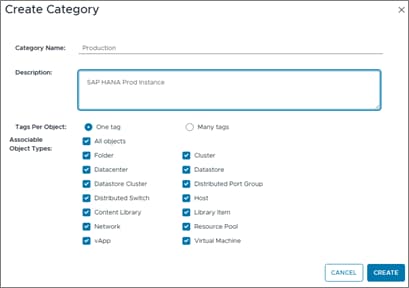
Procedure 1. Create Category and Tag
Step 1. In the vSphere client menu go to Tags & Custom Attributes > Assign Tag.
Step 2. In Assign Tag, click Add Tag.
Step 3. Create a new category (PRODUCTION) and enter a category description. Click Create.
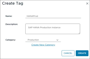
Step 4. Select the category. Enter a tag name (SAP HANA) and a description. Click Create.
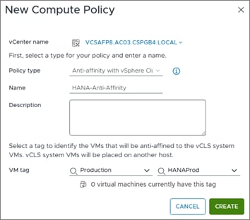
Procedure 2. Create Anti-Affinity policy for vCLS
Step 1. In the vSphere client menu select Policies and Profiles.
Step 2. Select Compute Policies and click Add.
Step 3. From the Policy type drop-down list, select Anti-affinity with vSphere Cluster Service.
Step 4. Enter a policy Name and policy Description.
Step 5. From the drop-down lists, select the category Production and tag HANAProd previously created, then click Create.
Enable EVC on the VMware Cluster
In cluster environments with mixed compute nodes and CPU architectures it is required to ensure CPU compatibility when planning to move VMs between hosts of different architectures. In addition, special attention requires the number of sockets, cores and main memory which must be adapted manually if required. Other cluster features such as vSphere DRS and vSphere HA are fully compatible with Enhanced vMotion Compatibility (EVC) .
Procedure 1. Enable EVC for Intel Hosts
Step 1. Go to Inventory > Hosts and Clusters and select the cluster object (AC03).
Step 2. Click the Configure tab, select Configuration - VMware EVC. Click Edit.
Step 3. Select Enable EVC for Intel Hosts.
Step 4. Select CPU mode Intel Sapphire Rapids (or suitable) generation.
Step 5. Make sure the Compatibility box displays Validation succeeded. Click OK.
Procedure 2. VMware ESXi 8.0 U3 TPM Attestation
Note: If your Cisco UCS servers have Trusted Platform Module (TPM) 2.0 modules installed, the TPM can provide assurance that ESXi has booted with UEFI Secure Boot enabled and using only digitally signed code. The UEFI secure boot was enabled in the boot order policy. A server can boot with UEFI Secure Boot with or without a TPM 2.0 module. If it has a TPM, VMware vCenter can attest that the server booted with UEFI Secure Boot. To verify the VMware ESXi 8.0 U3 TPM Attestation, follow these steps:
For Cisco UCS servers that have TPM 2.0 modules installed, TPM Attestation can be verified in the vSphere HTML5 Client.
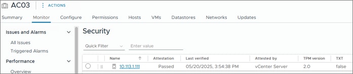
Step 1. In the vCenter HTML5 Interface, under Hosts and Clusters select the cluster.
Step 2. Click the Monitor tab.
Step 3. Click Monitor > Security from the menu. The Attestation status will show the status of the TPM. If no TPM module is installed, the status will display N/A:
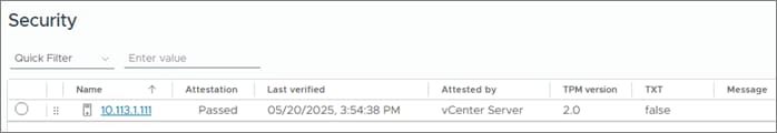
Note: It may be necessary to disconnect and reconnect or reboot a host from vCenter to get it to pass the attestation the first time.
Prepare the VM Host for SAP HANA
This chapter contains the following:
● Overview
● Deployment Options with VMware Virtualization
● SAP HANA on VMware vSphere Configuration and Sizing Guidelines
● SAP HANA Virtual Machine Configuration
The VMware vSphere 8.0U3 virtual machine or the bare metal node must be prepared to host the SAP HANA installation.
SAP HANA on Cisco UCS M7 2-socket nodes, either virtual or bare metal can be deployed as single-host system and while 4-socket node supports both single and multi-host systems.
Deployment Options with VMware Virtualization
The supported SAP HANA start release is SAP HANA 1.0 SPS 12 Revision 122.19; SAP HANA 2.0 is recommended. Make sure to review SAP Note 3372365 - SAP HANA on VMware vSphere 8.0 in production for the most current updates.
Besides SAP HANA, most SAP applications and databases can get virtualized and are fully supported for production workloads either on dedicated vSphere hosts or running consolidated side-by-side.
Table 3. Overview of SAP HANA on vSphere Deployment Options
| Host Socket Size |
Certified Configuration |
Virtual SAP HANA VM Sizes |
| 2-socket |
Cisco UCS X-Series M7 Intel Emerald Rapids <= 2 TiB per socket, max. 128 vCPUs per socket Intel Sapphire Rapids <= 2 TiB per socket (Class-M), max. 120 vCPUs per socket |
Scale-Up: 0.5 [Only with EMR, 1 and 2-socket wide VMs Scale-Out: N/A Min: 8 vCPUs and 128 GiB vRAM Up to 4 VMs per 2-socket host |
| 4-socket |
Cisco UCS X-Series M7 Intel Sapphire Rapids <= 2 TiB per socket, max. 120 vCPUs per socket |
Scale-Up: 0.5, 1 and 2-socket wide VMs Scale-Out: 0.5,1,2,4 socket wide VMs. Up to 6 TiB of RAM per Scale-Out node (VM) Min: 8 vCPUs and 128 GiB vRAM |
SAP HANA on VMware vSphere Configuration and Sizing Guidelines
SAP HANA must be sized according to the existing SAP HANA sizing guidelines and VMware recommendations. The sizing report provides information about the required CPU size (SAP Application Performance Standard (SAPS)), memory and storage resources.
The general sizing recommendation is to scale-up first; for production environments CPU and memory over-commitment must be avoided. Depending on workload-based sizing results (SAP Note 2779240 - Workload-based sizing for virtualized environments) a deviation from the existing core-to-memory ratio might be possible for virtualized HANA.
VMware vSphere uses datastores to store virtual disks. Datastores provide an abstraction of the storage layer that hides the physical attributes of the storage devices from the virtual machines. The datastores types applicable for FlexPod, such as VMFS, NFS or vSphere virtual volumes (vVols) are fully supported with SAP HANA deployments.
All SAP HANA instances do have an operating system, local SAP, database log, database data, and shared SAP volume. The storage sizing calculation of these volumes is based on the overall amount of memory the node is configured with.
The storage layout and sizing follow the guidelines per SAP Note 1900823. While the OS disk/partition is carved out from an already presented NFS datastore [infra_datastore], it is recommended to directly mount the NFS volumes for /usr/sap partition, /hana/data, /hana/log and /hana/shared filesystems inside the host VM.
SAP HANA Virtual Machine Configuration
With the virtualized SAP HANA system example requirements of full-socket CPU 512GiB RAM, the deployment procedure of a single SAP HANA instance can be executed as follows on a Cisco UCS X120C M7 compute node.
Procedure 1. Create an SAP HANA virtual machine
The new vHANA instance will use the available NFS datastore created earlier, which will keep the VMDKs of the OS.
Step 1. Go to Inventory > Hosts and Clusters.
Step 2. Right-click the cluster object (AC03) and select New Virtual Machine.
Step 3. Select the creation type Create a new virtual machine and click Next.
Step 4. Enter a virtual machine name (for example, vhanar94 or vhanasle156, depending on the OS) and click Next.
Step 5. Select the Compute resource to run the VM. Expand the cluster object and select the ESXi host. Click Next.
Step 6. Select the datastore (infra_datastore) and click Next.
Step 7. Keep the ESXi 8.0 U2 and later compatibility and click Next.
Step 8. Select Linux as Guest OS Family and either the Guest OS version Red Hat Enterprise Linux 9 or SUSE Linux Enterprise 15. based on the desired OS. Click Next.
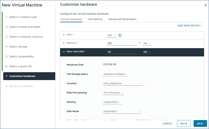
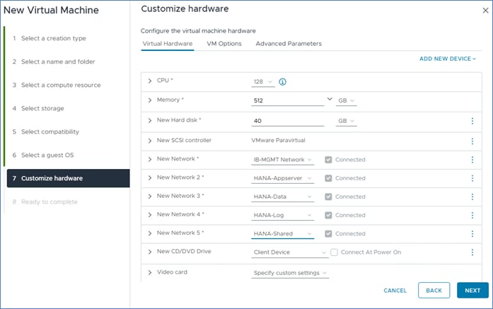
Step 9. From the drop-down list, enter 128 vCPUs.
Step 10. Expand the CPU entry and select 128.
Step 11. Enter the necessary memory (for example, 512GB). Expand the field and check the box for Reserve all guest memory (all locked).
Step 12. In the new hard disk field, enter 40 GB. Expand the field and change disk provisioning to thin provision.
Step 13. From the Location drop-down list, select Browse to change the location to infra_datastore.
Step 14. For the New Network first select the IB_MGMT network.
Step 15. Click Add New Device and from the drop-down list select Network - Network Adapter.
Step 16. From the New Network drop-down list, select Browse and select HANA-AppServer.
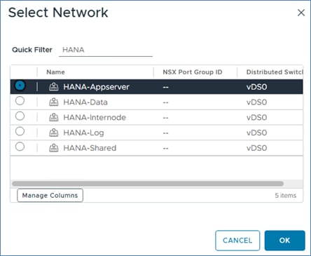
Step 17. Repeat steps 15 and 16 to add all required SAP HANA related networks.
Step 18. Change the New CD/DVD drive to Datastore ISO File and select your OS installation image.
Step 19. Select the checkmark field Connect then click Next.
Step 20. Review the configuration details and click Finish.
Procedure 2. vSphere Clustering Service deployment
Note: According to the SAP requirements, non-SAP HANA VMs should not run on the same NUMA (Non-Uniform Memory Access) node where a productive SAP HANA VM is already running. Additionally, no NUMA node sharing is allowed between SAP HANA and non-HANA virtual machines.
Step 1. Go to Inventory > Hosts and Clusters.
Step 2. Expand the cluster object (AC03) and select the virtual machine.
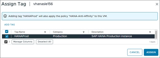
Step 3. In the Summary - Tags field select Assign Tag.
Step 4. Select the SAP HANA tag and click Assign.
Procedure 3. Operating System Installation
The Linux operating system installations follow the Red Hat or SLES specific SAP Notes:
● SAP Note 3108316 - RHEL 9.x: Installation and Configuration
● SAP Note 2578899 - SUSE Linux Enterprise Server 15: Installation Note
Step 1. Click Power On to start the virtual machine.
Step 2. Launch the web console.
Step 3. Follow the installation wizard. Detailed information on the installation process is available in the installation guides.
Step 4. Confirm the network adapter MAC address from the virtual machine Summary tab in the VM Hardware - Network Adapter status page to ensure to configure the correct network adapter.
Step 5. When the installation finishes, reboot the machine.
Step 6. From the virtual machine overview in the vSphere client, select Install VMware Tools.
Step 7. Click Actions > Guest OS - Install VMware Tools.
As soon as the vhanasle156 virtual machine is up, vSphere will check the VM is compliant with the Anti-Affinity policy previously created and move the vCLS virtual machine away from the host.
Step 8. Review the status in Virtual Machine Summary tab.
Procedure 4. Operating System Configuration
This procedure manually defines the file systems before the operating system configuration and SAP HANA installation.
Step 1. SSH into the virtual machine as root.
Step 2. Make sure to configure the recommended operating system settings according to the SAP notes and apply the latest security patches to the new system before installing SAP HANA.
● SAP Note 3108302 - SAP HANA DB: Recommended OS Settings for RHEL 9
● SAP Note 2684254 - SAP HANA DB: Recommended OS settings for SLES 15 / SLES for SAP Applications 15
Prepare Bare Metal Host for SAP HANA
This chapter contains the following:
● Access Cisco Intersight and Launch KVM with vMedia
● Linux OS Installation and Configuration
This chapter details the preparation of bare metal host for SAP HANA based on SLES for SAP Applications 15 SP6 and RHEL for SAP 9.4. It provides the Linux Operating System installation procedure including OS optimization to fulfill all SAP HANA requirements.
Access Cisco Intersight and Launch KVM with vMedia
The Cisco Intersight KVM enables the administrators to begin the installation of the operating system (OS) through remote media. It is necessary to log into the Cisco Intersight to access KVM.
Procedure 1. Log into Cisco Intersight and Access KVM
Step 1. Log into Cisco Intersight.
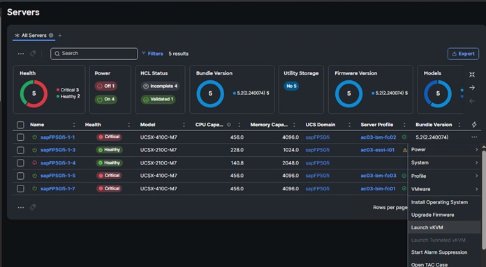
Step 2. From the main menu, go to Infrastructure Service > Servers.
Step 3. Find the Server with the desired Server Profile assigned and click … for more options.
Step 4. Click Launch vKVM.
Note: Since the Linux ISO image will be mapped to the vKVM, it is important to use the standard vKVM that the Cisco Intersight interface is being run from a subnet that has direct access to the subnet that the CIMC IPs (10.1113.0.121 in this example) are provisioned on.
Step 5. Follow the prompts and ignore certificate workings (if any) and launch the HTML5 KVM console.
Step 6. Repeat steps 1 - 5 to launch the HTML5 KVM console for all the needed compute nodes.
Linux OS Installation and Configuration
This section provides the procedure to install and configure the Linux OS.
Procedure 1. Prepare the Server for the OS Installation
Note: Follow these steps on each bare metal node.
Step 1. In the KVM window, click Virtual Media > vKVM-Mapped vDVD.
Step 2. Browse and select the RHEL or SLES ISO image file staged locally.
Step 3. Click Map Drive.
Step 4. Click Power > Reset System and Confirm to reboot the server if the server displays the shell prompt. If the server is shutdown, click Power > Power On System.
Step 5. Monitor the server boot process in the KVM. The server should find the boot LUNs and begin to load the OS installer.
Procedure 2. Install the Operating System
The Linux operating system installations follow the Red Hat or SLES specific SAP Notes:
● SAP Note 3108316 - RHEL 9.x: Installation and Configuration
● SAP Note 2578899 - SUSE Linux Enterprise Server 15: Installation Note
Procedure 3. Configure the Operating System
After the installation completes:
Step 1. SSH into the virtual machine as root.
Step 2. Make sure to configure the recommended operating system settings according to the SAP notes and apply the latest security patches to the new system before installing SAP HANA:
● SAP Note 3108302 - SAP HANA DB: Recommended OS Settings for RHEL 9
● SAP Note 2684254 - SAP HANA DB: Recommended OS settings for SLES 15 / SLES for SAP Applications 15
Storage Configuration – NetApp ONTAP SAP HANA Persistence Storage Setup
This chapter contains the following:
● Ansible ONTAP Storage Configuration – HANA SVM
In this chapter, the storage is configured to provide SAP HANA Persistence, primarily SAP HANA Data, Log, and Shared filesystems. This involves creating a separate SVM configuration for the tenant SAP HANA database.
Note: For bare metal installations, the recommendation is to leverage FC protocol for SAP HANA Data and Log mounts and NFS v3/4.1 for SAP HANA Shared filesystem. For virtualized SAP HANA, NFS v3/4.1 filesystems for SAP HANA Data, Log and Shared are directly mounted inside the VM host.
This configuration requires information from both the server profiles and NetApp storage system.
Ansible ONTAP Storage Configuration – HANA SVM
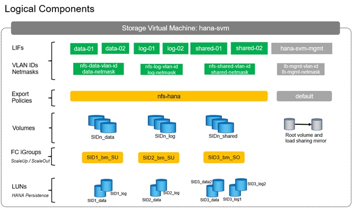
The following procedure includes the following tasks:
● Creating a dedicated IPspace for HANA tenant, then creating relevant broadcast-domains, application specific VLANs, adding VLANs to corresponding broadcast-domains.
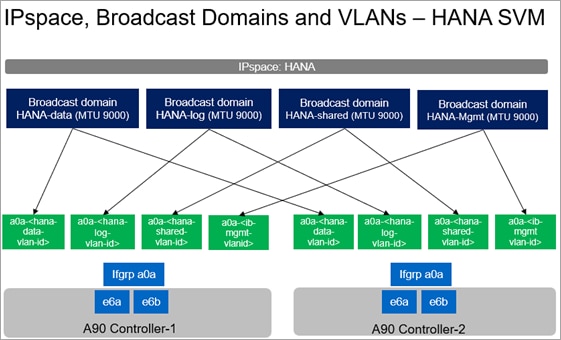
● Creating an SVM for HANA tenant and enabling the required protocols and services (FC and NFS) on the SVM.
● Creating logical interfaces (LIFs) for storage access, required volumes, and export policy for SAP HANA system persistence partitions.
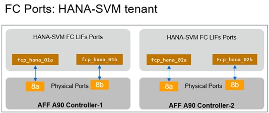
● Creating LUNs and SAP HANA database specific igroups to ensure access to respective HANA nodes.
Procedure 1. Configure ONTAP Storage for HANA SVM using Ansible
Step 1. Edit the following variable files to ensure the proper ONTAP tenant HANA specific storage variables are entered:
● FlexPod-M7-SAPHANA/group_vars_tenant/all.yml
● FlexPod-M7-SAPHANA/group_vars_tenant/secrets.yml
● FlexPod-M7-SAPHANA/vars_tenant/ontap_main.yml
Step 2. From FlexPod-M7-SAPHANA, invoke the ansible scripts for this section using the following command:
ansible-playbook -i inventory_tenant Setup_ONTAP_HANAtenant.yml
SAN Switch Configuration – Part 2 – Enable HANA Persistence Presentation to FC SAN Booting Bare-Metal Nodes
This chapter contains the following:
● FlexPod Cisco MDS Ansible Config – SAP HANA Specific Zoning
The following procedure configure the Cisco MDS switches with SAP HANA specific zoning. The configuration explained in this section is valid when configuring fibre channel storage access to SAP HANA Persistence LUNs. This is for FC booted bare-metal nodes being prepared for SAP HANA installation which would be presented with LUNs for /hana/data and /hana/log.
Note: For virtualized SAP HANA, database filesystems such as /hana/data, /hana/log and /hana/shared are NFS mounted directly inside the HANA VMs.
FlexPod Cisco MDS Ansible Config – SAP HANA Specific Zoning
The procedures accomplish the following configuration tasks:
● Create HANA-SVM Specific Device Alias for HANA Persistence LUNs Presentation
● Create HANA-SVM Specific zone and zonesets for HANA Persistence LUNs Presentation
Procedure 1. FlexPod Cisco MDS Switch Ansible Configuration – SAP HANA Specific Zoning
Step 1. Edit the following variable files to ensure the proper MDS variables are entered:
● FlexPod-M7-SAPHANA/group_vars_tenant/secrets.yml
● FlexPod-M7-SAPHANA/inventory_tenant
● FlexPod-M7-SAPHANA/group_vars_tenant/all.yml
● FlexPod-M7-SAPHANA/host_vars/mdsAtenant.yml
● FlexPod-M7-SAPHANA/host_vars/mdsBtenant.yml
● FlexPod-M7-SAPHANA/roles/MDSSAPHANA/defaults/main.yml
Note: The WWPN information of FC LIFs of HANA-SVM tenant should have been entered into the all.yml file. The Cisco UCS server initiator WWPNs for FC should also be entered into all.yml. To query these WWPNs, log into Cisco Intersight and select each of the FC boot based Server Profiles by accessing: Intersight > Profile > <server-profile> General > Configuration > vNICs/vHBAs tab.
Step 2. From FlexPod-M7-SAPHANA, run the Setup_MDS_HANAtenant.yml Ansible playbook:
ansible-playbook ./Setup_MDS_HANAtenant.yml -i inventory_tenant
Note: Smart licensing should be set up in the MDS switches. For more information see: Cisco MDS 9000 Series Licensing Guide, Release 9.x.
Step 3. Use the following commands to see the switch configuration and status:
show interface brief
show port-channel summary
show vsan membership
sh device-alias database
show zone
sh zoneset active
Node Preparation to Mount SAP HANA Persistence
This chapter contains the following:
● iSCSI Booting Virtualized SAP HANA Single-host Example (IP / NFS only setup)
● FC Booting Bare Metal SAP HANA Multi-host Example (FC and NFS setup)
Post OS installation and configuration, node is ready to host the SAP HANA persistence partitions either via FC or NFS depending on whether it is a NFS only or FC w/ NFS setup.
iSCSI booting virtualized SAP HANA single-host example (IP / NFS only setup)
Required NFS volumes for the single-host system were created in the previous section.
Procedure 1. Host preparation - Create Mount Points
Step 1. Create the required mount-point directories by running one of the following:
mkdir -p /hana/data/VSU/mnt00001
mkdir -p /hana/log/VSU/mnt00001
mkdir -p /hana/shared
mkdir -p /usr/sap/VSU
chmod 777 -R /hana/log/VSU
chmod 777 -R /hana/data/VSU
chmod 777 -R /hana/shared
chmod 777 -R /usr/sap/VSU
Procedure 2. Verify Domain Information Synchronization
To be able to mount the volumes inside the HANA nodes, the v4-id-domain information of NFS enabled HANA-SVM providing the database persistence access should match the domain information in /etc/idmapd.conf of the HANA nodes.
Step 1. Configure the desired v4 domain information for the storage system:
AC03-A90::> vserver nfs modify -vserver HANA-SVM -v4-id-domain nfsv4domain.flexpod.com
Step 2. Compare the value on NetApp and /etc/idmapd.conf file of the HANA node to verify they are synchronized:
AC03-A90::> nfs show -vserver HANA-SVM -fields v4-id-domain
vserver v4-id-domain
------------- ---------------------
AA07-HANA-SVM nfsv4domain.flexpod.com
[root@vhanasle156~]# vi /etc/idmapd.conf
[General]
#Verbosity = 0
# The following should be set to the local NFSv4 domain name
# The default is the host's DNS domain name.
Domain = nfsv4domain.flexpod.com
The mount options are identical for all file systems that are mounted to the host:
● /hana/data/VSU/mnt00001
● /hana/log/VSU/mnt00001
● /hana/shared
● /usr/sap/VSU
Table 4 lists the required mount options.
This example uses NFSv4.1 to connect to the storage. However, NFSv3 is also supported for SAP HANA systems.
For NFSv3, NFS locking must be switched off to avoid NFS lock cleanup operations in case of software or server failure.
With NetApp ONTAP 9, the NFS transfer size can be configured up to 1MB. Specifically, with connections to the storage system over 10GBE, you must set the transfer size to 1MB to achieve the expected throughput values.
| Common Parameter |
NFSv4.1 |
NFS Transfer Size with ONTAP 9 |
| rw, bg, hard, timeo=600, intr, noatime |
vers=4, minorversion=1, lock |
rsize=1048576, wsize=1048576 |
Procedure 1. Mount the File Systems during System Boot using the /etc/fstab Configuration File
Note: The following examples show an SAP HANA database with SID=VSU using NFSv4.1 and an NFS transfer size of 1MB.
Step 1. Add the file systems to the /etc/fstab configuration file:
cat /etc/fstab
<node01-data_lif01-ip>:/VSU_data_mnt00001 /hana/data/VSU/mnt00001 nfs rw,bg,vers=4,minorversion=1,hard,timeo=600,rsize=1048576,wsize=1048576,intr,noatime,lock 0 0
<node02-log_lif02-ip>:/VSU_log_mnt00001 /hana/log/VSU/mnt00001 nfs rw,bg,vers=4,minorversion=1,hard,timeo=600,rsize=1048576,wsize=1048576,intr,noatime,lock 0 0
<node01-shared_lif01-ip>:/VSU_shared/usr-sap /usr/sap/VSU nfs rw,bg,vers=4,minorversion=1,hard,timeo=600,rsize=1048576,wsize=1048576,intr,noatime,lock 0 0
<node02-shared_lif02-ip>:/VSU_shared/shared /hana/shared nfs rw,bg,vers=4,minorversion=1,hard,timeo=600,rsize=1048576,wsize=1048576,intr,noatime,lock 0 0
Step 2. Run mount –a to mount the file systems on the host.
Step 3. Ensure the mounts have the ownership root:root and 777 for permissions, previously set:
[root@vhanar86 ~]# df -h
Filesystem Size Used Avail Use% Mounted on
devtmpfs 126G 0 126G 0% /dev
tmpfs 126G 0 126G 0% /dev/shm
tmpfs 126G 17M 126G 1% /run
tmpfs 126G 0 126G 0% /sys/fs/cgroup
/dev/mapper/rhel-root 45G 3.5G 41G 8% /
/dev/sda2 1014M 223M 792M 22% /boot
/dev/sda1 599M 5.8M 594M 1% /boot/efi
xx.xxx.4.1:/VSU_data_mnt00001 768G 3.0G 752G 1% /hana/data/VSU/mnt00001
xx.xxx.6.2:/VSU_log_mnt00001 256G 5.9G 242G 3% /hana/log/VSU/mnt00001
xx.xxx.7.1:/VSU_shared/usr-sap 512G 4G 511G 5% /usr/sap/VSU
xx.xxx.7.2:/VSU_shared/shared 512G 4G 511G 5% /hana/shared
tmpfs 26G 0 26G 0% /run/user/1000
tmpfs 26G 0 26G 0% /run/user/0
Note: It is very important to ensure the ownership of mount points, and their recursive directories are set to root:root and permissions to 777 before processing with SAP HANA installation.
FC Booting Bare Metal SAP HANA Multi-host Example (FC and NFS setup)
Before setting up the host, NetApp SAN host utilities must be downloaded from the NetApp Support site and installed on the HANA servers. The host utility documentation includes information about additional software that must be installed depending on the FCP HBA used.
The documentation also contains information on multipath configurations that are specific to the Linux version used. This document explains the required configuration steps for SLES 15 series and RHEL 9 series, as described in the Linux Host Utilities 7.1 Installation and Setup Guide.
Procedure 1. Configure Multipathing
Step 1. Run the rescan-scsi-bus.sh -a command on each server to discover new LUNs.
Step 2. Run the sanlun lun show command and verify that all required LUNs are visible. The following example shows the sanlun lun show command output from one of 2+1 multi-host HANA system nodes with two data LUNs, two LOG LUNs, and a LUN for /hana/shared. The output shows the LUNs and the corresponding device files, such as LUN FCS_data_mnt00001 and the device file /dev/sd*. Each LUN has four FC paths from the host to the storage controllers:
[root@fcbmso-hana03 ~]# sanlun lun show
controller(7mode/E-Series)/ device host lun
vserver(cDOT/FlashRay) lun-pathname filename adapter protocol size product
-------------------------------------------------------------------------------------------------------------------------
HANA-SVM /vol/HSO_log_mnt00002/HSO_log_mnt00002 /dev/sdw host4 FCP 512g cDOT
HANA-SVM /vol/HSO_data_mnt00002/HSO_data_mnt00002 /dev/sdv host4 FCP 6t cDOT
HANA-SVM /vol/HSO_data_mnt00001/HSO_data_mnt00001 /dev/sdt host4 FCP 6t cDOT
HANA-SVM /vol/HSO_log_mnt00001/HSO_log_mnt00001 /dev/sdu host4 FCP 512g cDOT
Infra-SVM /vol/bm_boot/ac03-bm-fc03-FCP /dev/sds host4 FCP 90g cDOT
HANA-SVM /vol/HSO_log_mnt00002/HSO_log_mnt00002 /dev/sdq host4 FCP 512g cDOT
HANA-SVM /vol/HSO_data_mnt00002/HSO_data_mnt00002 /dev/sdp host4 FCP 6t cDOT
HANA-SVM /vol/HSO_log_mnt00001/HSO_log_mnt00001 /dev/sdo host4 FCP 512g cDOT
HANA-SVM /vol/HSO_data_mnt00001/HSO_data_mnt00001 /dev/sdn host4 FCP 6t cDOT
HANA-SVM /vol/HSO_data_mnt00002/HSO_data_mnt00002 /dev/sdk host5 FCP 6t cDOT
HANA-SVM /vol/HSO_log_mnt00002/HSO_log_mnt00002 /dev/sdl host5 FCP 512g cDOT
HANA-SVM /vol/HSO_log_mnt00001/HSO_log_mnt00001 /dev/sdj host5 FCP 512g cDOT
HANA-SVM /vol/HSO_data_mnt00001/HSO_data_mnt00001 /dev/sdi host5 FCP 6t cDOT
Infra-SVM /vol/bm_boot/ac03-bm-fc03-FCP /dev/sdh host5 FCP 90g cDOT
HANA-SVM /vol/HSO_log_mnt00002/HSO_log_mnt00002 /dev/sdf host5 FCP 512g cDOT
HANA-SVM /vol/HSO_data_mnt00002/HSO_data_mnt00002 /dev/sde host5 FCP 6t cDOT
HANA-SVM /vol/HSO_log_mnt00001/HSO_log_mnt00001 /dev/sdd host5 FCP 512g cDOT
HANA-SVM /vol/HSO_data_mnt00001/HSO_data_mnt00001 /dev/sdc host5 FCP
Step 3. Run the multipath -ll command to get the worldwide identifiers (WWIDs) for the device file names:
Note: In this example, there are four LUNs.
[root@fcbmso-hana03 ~]# multipath -ll
3600a098038314f6c4c5d59382d594d7a dm-1 NETAPP,LUN C-Mode
size=512G features='3 queue_if_no_path pg_init_retries 50' hwhandler='1 alua' wp=rw
|-+- policy='service-time 0' prio=50 status=active
| |- 4:0:0:1 sdo 8:224 active ready running
| `- 5:0:2:1 sdj 8:144 active ready running
`-+- policy='service-time 0' prio=10 status=enabled
|- 4:0:2:1 sdu 65:64 active ready running
`- 5:0:0:1 sdd 8:48 active ready running
3600a098038314f6c4c5d59382d594e30 dm-3 NETAPP,LUN C-Mode
size=512G features='3 queue_if_no_path pg_init_retries 50' hwhandler='1 alua' wp=rw
|-+- policy='service-time 0' prio=50 status=active
| |- 4:0:0:3 sdq 65:0 active ready running
| `- 5:0:2:3 sdl 8:176 active ready running
`-+- policy='service-time 0' prio=10 status=enabled
|- 4:0:2:3 sdw 65:96 active ready running
`- 5:0:0:3 sdf 8:80 active ready running
3600a098038314f6c663f586c45597851 dm-5 NETAPP,LUN C-Mode
size=90G features='3 queue_if_no_path pg_init_retries 50' hwhandler='1 alua' wp=rw
|-+- policy='service-time 0' prio=50 status=active
| `- 4:0:1:0 sds 65:32 active ready running
`-+- policy='service-time 0' prio=10 status=enabled
`- 5:0:1:0 sdh 8:112 active ready running
3600a098038314f6c663f586c45597856 dm-0 NETAPP,LUN C-Mode
size=6.0T features='3 queue_if_no_path pg_init_retries 50' hwhandler='1 alua' wp=rw
|-+- policy='service-time 0' prio=50 status=active
| |- 4:0:2:0 sdt 65:48 active ready running
| `- 5:0:0:0 sdc 8:32 active ready running
`-+- policy='service-time 0' prio=10 status=enabled
|- 4:0:0:0 sdn 8:208 active ready running
`- 5:0:2:0 sdi 8:128 active ready running
3600a098038314f6c663f586c45597857 dm-2 NETAPP,LUN C-Mode
size=6.0T features='3 queue_if_no_path pg_init_retries 50' hwhandler='1 alua' wp=rw
|-+- policy='service-time 0' prio=50 status=active
| |- 4:0:2:2 sdv 65:80 active ready running
| `- 5:0:0:2 sde 8:64 active ready running
`-+- policy='service-time 0' prio=10 status=enabled
|- 4:0:0:2 sdp 8:240 active ready running
`- 5:0:2:2 sdk 8:160 active ready running
Step 4. Edit the /etc/multipath.conf file and add the WWIDs and alias names:
Note: If there is no multipath.conf file available, you can create one by running the following command: multipath -T > /etc/multipath.conf.
[root@fcbmso-hana03 ~] # cat /etc/multipath.conf
multipaths {
multipath {
wwid 3600a098038314f6c663f586c45597856
alias hana-svm-FCS_data_mnt00001
}
multipath {
wwid 3600a098038314f6c4c5d59382d594d7a
alias hana-svm-HSO_log_mnt00001
}
multipath {
wwid 3600a098038314f6c663f586c45597857
alias hana-svm-FCS_data_mnt00002
}
multipath {
wwid 3600a098038314f6c4c5d59382d594e30
alias hana-svm-HSO_log_mnt00002
}
}
Step 5. Run the multipath -r command to reload the device map.
Step 6. Verify the configuration by running the multipath -ll command to list all the LUNs, alias names, and active and standby paths.
Note: The multipath device dm-0 is the boot LUN from the Infra-SVM.
[root@fcbmso-hana03 ~]# multipath -ll
3600a098038314f6c663f586c45597851 dm-5 NETAPP,LUN C-Mode
size=90G features='3 queue_if_no_path pg_init_retries 50' hwhandler='1 alua' wp=rw
|-+- policy='service-time 0' prio=50 status=active
| `- 4:0:1:0 sds 65:32 active ready running
`-+- policy='service-time 0' prio=10 status=enabled
`- 5:0:1:0 sdh 8:112 active ready running
hana-svm-HSO_data_mnt00001 (3600a098038314f6c663f586c45597856) dm-0 NETAPP,LUN C-Mode
size=6.0T features='3 queue_if_no_path pg_init_retries 50' hwhandler='1 alua' wp=rw
|-+- policy='service-time 0' prio=50 status=active
| |- 4:0:2:0 sdt 65:48 active ready running
| `- 5:0:0:0 sdc 8:32 active ready running
`-+- policy='service-time 0' prio=10 status=enabled
|- 4:0:0:0 sdn 8:208 active ready running
`- 5:0:2:0 sdi 8:128 active ready running
hana-svm-HSO_data_mnt00002 (3600a098038314f6c663f586c45597857) dm-2 NETAPP,LUN C-Mode
size=6.0T features='3 queue_if_no_path pg_init_retries 50' hwhandler='1 alua' wp=rw
|-+- policy='service-time 0' prio=50 status=active
| |- 4:0:2:2 sdv 65:80 active ready running
| `- 5:0:0:2 sde 8:64 active ready running
`-+- policy='service-time 0' prio=10 status=enabled
|- 4:0:0:2 sdp 8:240 active ready running
`- 5:0:2:2 sdk 8:160 active ready running
hana-svm-HSO_log_mnt00001 (3600a098038314f6c4c5d59382d594d7a) dm-1 NETAPP,LUN C-Mode
size=512G features='3 queue_if_no_path pg_init_retries 50' hwhandler='1 alua' wp=rw
|-+- policy='service-time 0' prio=50 status=active
| |- 4:0:0:1 sdo 8:224 active ready running
| `- 5:0:2:1 sdj 8:144 active ready running
`-+- policy='service-time 0' prio=10 status=enabled
|- 4:0:2:1 sdu 65:64 active ready running
`- 5:0:0:1 sdd 8:48 active ready running
hana-svm-HSO_log_mnt00002 (3600a098038314f6c4c5d59382d594e30) dm-3 NETAPP,LUN C-Mode
size=512G features='3 queue_if_no_path pg_init_retries 50' hwhandler='1 alua' wp=rw
|-+- policy='service-time 0' prio=50 status=active
| |- 4:0:0:3 sdq 65:0 active ready running
| `- 5:0:2:3 sdl 8:176 active ready running
`-+- policy='service-time 0' prio=10 status=enabled
|- 4:0:2:3 sdw 65:96 active ready running
`- 5:0:0:3 sdf 8:80 active ready running
Procedure 2. Create File Systems
Step 1. Create the XFS file system on each LUN belonging to the HANA system, by running the following commands:
[root@fcbmso-hana03 ~]# mkfs.xfs -f /dev/mapper/hana-svm-HSO_data_mnt00001
[root@fcbmso-hana03 ~]# mkfs.xfs -f /dev/mapper/hana-svm-HSO_log_mnt00001
[root@fcbmso-hana03 ~]# mkfs.xfs -f /dev/mapper/hana-svm-HSO_data_mnt00002
[root@fcbmso-hana03 ~]# mkfs.xfs -f /dev/mapper/hana-svm-HSO_log_mnt00002
Procedure 3. Create Mount Points
Step 1. Create the required mount-point directories by running the following commands:
mkdir -p /hana/data/HSO/mnt00001
mkdir -p /hana/log/HSO/mnt00001
mkdir -p /hana/data/HSO/mnt00002
mkdir -p /hana/log/HSO/mnt00002
mkdir -p /hana/shared
mkdir -p /usr/sap/HSO
chmod 777 -R /hana/log/HSO
chmod 777 -R /hana/data/HSO
chmod 777 -R /hana/shared
chmod 777 -R /usr/sap/HSO
Procedure 4. Mount File Systems during System Boot using /etc/fstab Configuration File
Step 1. Add the required file systems to the /etc/fstab configuration file.
Note: The XFS file systems for the data and log LUNs must be mounted with the relatime and inode64 mount options.
[root@fcbmso-hana03 ~]# cat /etc/fstab
/dev/mapper/hana-svm-HSO_log_mnt00001 /hana/log/HSO/mnt00001 xfs relatime,inode64 0 0
/dev/mapper/hana-svm-HSO_data_mnt00001 /hana/data/HSO/mnt00001 xfs relatime,inode64 0 0
/dev/mapper/hana-svm-HSO_log_mnt00002 /hana/log/HSO/mnt00002 xfs relatime,inode64 0 0
/dev/mapper/hana-svm-HSO_data_mnt00002 /hana/data/HSO/mnt00002 xfs relatime,inode64 0 0
xx.xxx.7.10:/HSO_shared /hana/shared nfs rw,bg,vers=4,minorversion=1,hard,timeo=600,rsize=1048576,wsize=1048576,intr,noatime,lock 0 0
Step 2. Run mount –a to mount the file systems on the host.
Step 3. Ensure the mounts have the ownership root:root and 777 for permissions, as previously set:
[[root@fcbmso-hana03 ~]# df -h
Filesystem Size Used Avail Use% Mounted on
devtmpfs 4.0M 0 4.0M 0% /dev
tmpfs 2.0T 0 2.0T 0% /dev/shm
tmpfs 807G 15M 807G 1% /run
/dev/mapper/system-rootlv 80G 3.1G 77G 4% /
/dev/mapper/hana-svm-HSO_data_mnt00001 6.0T 43G 6.0T 1% /hana/data/HSO/mnt00001
/dev/mapper/hana-svm-HSO_data_mnt00002 6.0T 43G 6.0T 1% /hana/data/HSO/mnt00002
/dev/mapper/hana-svm-HSO_log_mnt00001 512G 3.6G 509G 1% /hana/log/HSO/mnt00001
/dev/mapper/3600a098038314f6c663f586c45597851p2 960M 227M 734M 24% /boot
/dev/mapper/hana-svm-HSO_log_mnt00002 512G 3.6G 509G 1% /hana/log/HSO/mnt00002
/dev/mapper/3600a098038314f6c663f586c45597851p1 599M 7.1M 592M 2% /boot/efi
tmpfs 404G 4.0K 404G 1% /run/user/0
xx.xxx.7.10:/HSO_shared 1.5T 0 1.5T 0% /hana/shared
Note: It is very important to ensure the ownership of mount points, and their recursive directories are set to root:root and permissions to 777 before processing with SAP HANA installation.
SAP HANA Installation
Please refer to the official SAP documentation, SAP HANA Server Installation and Update Guide, which describes the SAP HANA installation process with and without the SAP unified installer.
Afterwards, prepare the additional virtual machines to install SAP S/4HANA or SAP BW/4HANA and follow the SAP master and installation guides.
About the Authors
Pramod Ramamurthy, Technical Marketing Engineer, Cloud and Compute Group, Cisco Systems GmbH.
Pramod has over eleven years of experience at Cisco Systems with data center technologies and enterprise solution architecture. He has over ten years of SAP Basis experience from previous roles helping customers with their SAP landscapes design, build, management, and support. As a Technical Marketing Engineer with the Computing Systems Product Group’s UCS and SAP solutions team, Pramod focuses on Converged Infrastructure Solutions design, validation and associated collaterals build for SAP and SAP HANA.
Kamini Singh, Technical Marketing Engineer, Hybrid Cloud Infra & OEM Solutions, NetApp, Inc.
Kamini Singh is a Technical Marketing engineer at NetApp. She has six years of experience in data center infrastructure solutions. She focuses on FlexPod hybrid cloud infrastructure solution design, implementation, validation, automation, and sales enablement. Kamini holds a bachelor’s degree in Electronics and Communication and a master’s degree in Communication Systems.
Acknowledgements
For their support and contribution to the design, validation, and creation of this Cisco Validated Design, the authors would like to thank:
● John George, Technical Marketing Engineer, Cisco Systems, Inc.
● Joerg Wolters, Technical Marketing Engineer, Cisco Systems, Inc.
● Bobby Oommen, Sr. Manager FlexPod Solutions, NetApp, Inc.
● Marco Schoen, Senior Technical Marketing Engineer, NetApp, Inc.
Feedback
For comments and suggestions about this guide and related guides, join the discussion on Cisco Community here: https://cs.co/en-cvds.
CVD Program
"DESIGNS") IN THIS MANUAL ARE PRESENTED "AS IS," WITH ALL FAULTS. CISCO AND ITS SUPPLIERS DISCLAIM ALL WARRANTIES, INCLUDING, WITHOUT LIMITATION, THE WARRANTY OF MERCHANTABILITY, FITNESS FOR A PARTICULAR PURPOSE AND NONINFRINGEMENT OR ARISING FROM A COURSE OF DEALING, USAGE, OR TRADE PRACTICE. IN NO EVENT SHALL CISCO OR ITS SUPPLIERS BE LIABLE FOR ANY INDIRECT, SPECIAL, CONSEQUENTIAL, OR INCIDENTAL DAMAGES, INCLUDING, WITHOUT LIMITATION, LOST PROFITS OR LOSS OR DAMAGE TO DATA ARISING OUT OF THE USE OR INABILITY TO USE THE DESIGNS, EVEN IF CISCO OR ITS SUPPLIERS HAVE BEEN ADVISED OF THE POSSIBILITY OF SUCH DAMAGES.
THE DESIGNS ARE SUBJECT TO CHANGE WITHOUT NOTICE. USERS ARE SOLELY RESPONSIBLE FOR THEIR APPLICATION OF THE DESIGNS. THE DESIGNS DO NOT CONSTITUTE THE TECHNICAL OR OTHER PROFESSIONAL ADVICE OF CISCO, ITS SUPPLIERS OR PARTNERS. USERS SHOULD CONSULT THEIR OWN TECHNICAL ADVISORS BEFORE IMPLEMENTING THE DESIGNS. RESULTS MAY VARY DEPENDING ON FACTORS NOT TESTED BY CISCO.
CCDE, CCENT, Cisco Eos, Cisco Lumin, Cisco Nexus, Cisco StadiumVision, Cisco TelePresence, Cisco WebEx, the Cisco logo, DCE, and Welcome to the Human Network are trademarks; Changing the Way We Work, Live, Play, and Learn and Cisco Store are service marks; and Access Registrar, Aironet, AsyncOS, Bringing the Meeting To You, Catalyst, CCDA, CCDP, CCIE, CCIP, CCNA, CCNP, CCSP, CCVP, Cisco, the Cisco Certified Internetwork Expert logo, Cisco IOS, Cisco Press, Cisco Systems, Cisco Systems Capital, the Cisco Systems logo, Cisco Unified Computing System (Cisco UCS), Cisco UCS B-Series Blade Servers, Cisco UCS C-Series Rack Servers, Cisco UCS S-Series Storage Servers, Cisco UCS X-Series, Cisco UCS Manager, Cisco UCS Management Software, Cisco Unified Fabric, Cisco Application Centric Infrastructure, Cisco Nexus 9000 Series, Cisco Nexus 7000 Series. Cisco Prime Data Center Network Manager, Cisco NX-OS Software, Cisco MDS Series, Cisco Unity, Collaboration Without Limitation, EtherFast, EtherSwitch, Event Center, Fast Step, Follow Me Browsing, FormShare, GigaDrive, HomeLink, Internet Quotient, IOS, iPhone, iQuick Study, LightStream, Linksys, MediaTone, MeetingPlace, MeetingPlace Chime Sound, MGX, Networkers, Networking Academy, Network Registrar, PCNow, PIX, PowerPanels, ProConnect, ScriptShare, SenderBase, SMARTnet, Spectrum Expert, StackWise, The Fastest Way to Increase Your Internet Quotient, TransPath, WebEx, and the WebEx logo are registered trade-marks of Cisco Systems, Inc. and/or its affiliates in the United States and certain other countries. (LDW_P1)
All other trademarks mentioned in this document or website are the property of their respective owners. The use of the word partner does not imply a partnership relationship between Cisco and any other company. (0809R)

