FlexPod Datacenter with VMware vSphere 7.0, Cisco VXLAN Single-Site Fabric, and NetApp ONTAP 9.7
Available Languages
Bias-Free Language
The documentation set for this product strives to use bias-free language. For the purposes of this documentation set, bias-free is defined as language that does not imply discrimination based on age, disability, gender, racial identity, ethnic identity, sexual orientation, socioeconomic status, and intersectionality. Exceptions may be present in the documentation due to language that is hardcoded in the user interfaces of the product software, language used based on RFP documentation, or language that is used by a referenced third-party product. Learn more about how Cisco is using Inclusive Language.
- US/Canada 800-553-2447
- Worldwide Support Phone Numbers
- All Tools
 Feedback
 Feedback

FlexPod Datacenter with VMware vSphere 7.0, Cisco VXLAN Single-Site Fabric, and NetApp ONTAP 9.7
Deployment Guide for FlexPod Datacenter with VMware vSphere 7.0, Cisco VXLAN BGP EVPN Single-Site Fabric, and NetApp ONTAP 9.7
Published: November 2020

In partnership with:
![]()
About the Cisco Validated Design Program
The Cisco Validated Design (CVD) program consists of systems and solutions designed, tested, and documented to facilitate faster, more reliable, and more predictable customer deployments. For more information, go to:
http://www.cisco.com/go/designzone.
ALL DESIGNS, SPECIFICATIONS, STATEMENTS, INFORMATION, AND RECOMMENDATIONS (COLLECTIVELY, "DESIGNS") IN THIS MANUAL ARE PRESENTED "AS-IS," WITH ALL FAULTS. CISCO AND ITS SUPPLIERS DISCLAIM ALL WARRANTIES, INCLUDING, WITHOUT LIMITATION, THE WARRANTY OF MERCHANTABILITY, FITNESS FOR A PARTICULAR PURPOSE AND NONINFRINGEMENT OR ARISING FROM A COURSE OF DEALING, USAGE, OR TRADE PRACTICE. IN NO EVENT SHALL CISCO OR ITS SUPPLIERS BE LIABLE FOR ANY INDIRECT, SPECIAL, CONSEQUENTIAL, OR INCIDENTAL DAMAGES, INCLUDING, WITHOUT LIMITATION, LOST PROFITS OR LOSS OR DAMAGE TO DATA ARISING OUT OF THE USE OR INABILITY TO USE THE DESIGNS, EVEN IF CISCO OR ITS SUPPLIERS HAVE BEEN ADVISED OF THE POSSIBILITY OF SUCH DAMAGES.
THE DESIGNS ARE SUBJECT TO CHANGE WITHOUT NOTICE. USERS ARE SOLELY RESPONSIBLE FOR THEIR APPLICATION OF THE DESIGNS. THE DESIGNS DO NOT CONSTITUTE THE TECHNICAL OR OTHER PROFESSIONAL ADVICE OF CISCO, ITS SUPPLIERS OR PARTNERS. USERS SHOULD CONSULT THEIR OWN TECHNICAL ADVISORS BEFORE IMPLEMENTING THE DESIGNS. RESULTS MAY VARY DEPENDING ON FACTORS NOT TESTED BY CISCO.
CCDE, CCENT, Cisco Eos, Cisco Lumin, Cisco Nexus, Cisco StadiumVision, Cisco TelePresence, Cisco WebEx, the Cisco logo, DCE, and Welcome to the Human Network are trademarks; Changing the Way We Work, Live, Play, and Learn and Cisco Store are service marks; and Access Registrar, Aironet, AsyncOS, Bringing the Meeting To You, Catalyst, CCDA, CCDP, CCIE, CCIP, CCNA, CCNP, CCSP, CCVP, Cisco, the Cisco Certified Internetwork Expert logo, Cisco IOS, Cisco Press, Cisco Systems, Cisco Systems Capital, the Cisco Systems logo, Cisco Unified Computing System (Cisco UCS), Cisco UCS B-Series Blade Servers, Cisco UCS C-Series Rack Servers, Cisco UCS S-Series Storage Servers, Cisco UCS Manager, Cisco UCS Management Software, Cisco Unified Fabric, Cisco Application Centric Infrastructure, Cisco Nexus 9000 Series, Cisco Nexus 7000 Series. Cisco Prime Data Center Network Manager, Cisco NX-OS Software, Cisco MDS Series, Cisco Unity, Collaboration Without Limitation, EtherFast, EtherSwitch, Event Center, Fast Step, Follow Me Browsing, FormShare, GigaDrive, HomeLink, Internet Quotient, IOS, iPhone, iQuick Study, LightStream, Linksys, MediaTone, MeetingPlace, MeetingPlace Chime Sound, MGX, Networkers, Networking Academy, Network Registrar, PCNow, PIX, PowerPanels, ProConnect, ScriptShare, SenderBase, SMARTnet, Spectrum Expert, StackWise, The Fastest Way to Increase Your Internet Quotient, TransPath, WebEx, and the WebEx logo are registered trademarks of Cisco Systems, Inc. and/or its affiliates in the United States and certain other countries.
All other trademarks mentioned in this document or website are the property of their respective owners. The use of the word partner does not imply a partnership relationship between Cisco and any other company. (0809R)
© 2020 Cisco Systems, Inc. All rights reserved.
Contents
Solution Deployment - Network Fabric
Storage Configuration - Boot LUNs and Igroups
Solution Deployment - VMware vSphere
Solution Deployment - Management Tools
Solution Deployment - Sample Tenant Provisioning
Cisco Validated Designs (CVDs) include systems and solutions that are designed, tested, and documented to facilitate and improve customer deployments. These designs incorporate a wide range of technologies and products into a portfolio of solutions that have been developed to address the business needs of customers. Cisco and NetApp have partnered to deliver FlexPod, which serves as the foundation for a variety of workloads and deliver architectural designs that are robust, efficient, and scalable to address customer requirements. A FlexPod solution is a validated approach for deploying Cisco and NetApp technologies and products for building shared private and public cloud infrastructure.
FlexPod is a widely deployed architecture in today’s on-premise, private cloud infrastructure and though cloud adoption is growing, businesses still have a need for private cloud infrastructure. To support the on-premise infrastructure, Enterprises also require a scalable data center network that is easy-to-manage. This FlexPod solution expands the existing portfolio of FlexPod solutions by enabling customers to deploy a standards-based, datacenter fabric that can be used in a heterogenous environment. The FlexPod infrastructure in this CVD incorporates a Cisco VXLAN BGP EVPN (Virtual Extensible LAN - Border Gateway Protocol - Ethernet VPN) network architecture to allow for greatly expanded network scale, with the potential to extend that network between locations as a contiguous fabric. This expanded FlexPod solution also includes the AI powered analytics of both Cisco Intersight and NetApp Active IQ from the base FlexPod design for infrastructure management and operational intelligence.
This document describes the deployment of the Cisco and NetApp® FlexPod Datacenter with NetApp ONTAP 9.7 on NetApp AFF A300 storage, Cisco UCS Manager unified software release 4.1(2) with 2nd Generation Intel Xeon Scalable Processors, VMware vSphere 7.0, and Cisco DCNM 11.4(1) managed Cisco VXLAN BGP EVPN design implemented on Cisco Nexus switches running NX-OS 9.3(5). Cisco UCS Manager (UCSM) 4.1(2) provides consolidated support of all current Cisco UCS Fabric Interconnect models (6200, 6300, 6324 (Cisco UCS Mini)), 6400, 2200/2300/2400 series IOM, Cisco UCS B-Series, and Cisco UCS C-Series. Cisco DCNM 11 provides multi-tenant, multi-fabric (LAN, SAN) infrastructure management and automation that is optimized for large deployments though it can support smaller and more traditional network architectures as well. Also included are Cisco Intersight and NetApp Active IQ SaaS management platforms.
The industry trend in today’s data center design is to move away from application silos and towards a shared infrastructure by using virtualization and pre-validated IT platforms to quickly deploy resources, thereby increasing agility, and reducing costs. Cisco and NetApp have partnered to deliver FlexPod, which uses best of breed storage, server, and network components to serve as the foundation for a variety of workloads, enabling efficient architectural designs that can be quickly and confidently deployed. This FlexPod Datacenter solution with NetApp ONTAP 9.7, Cisco UCS unified software release 4.1(2), and VMware vSphere 7.0 is a predesigned, best-practice datacenter architecture built on the Cisco Unified Computing System (Cisco UCS), the Cisco Nexus® 9000 family of switches, and NetApp AFF A-Series storage arrays running ONTAP® 9.7.
The audience for this document includes, but is not limited to; sales engineers, field consultants, professional services, IT managers, partner engineers, and customers who want to take advantage of an infrastructure built to deliver IT efficiency and enable IT innovation.
This document provides a step-by-step configuration and implementation guide for the FlexPod Datacenter with Cisco UCS Fabric Interconnects, NetApp AFF storage, and a Cisco DCNM managed VXLAN BGP EVPN network fabric built using Cisco Nexus 9000 series switches.
The following design elements distinguish this version of FlexPod from previous FlexPod models:
● A highly scalable, standards based VXLAN BGP EVPN data center fabric built using Cisco Nexus 9000 series switches
● Datacenter network deployed a managed as a single fabric using Cisco Data Center Network Manager (Cisco DCNM)-LAN Fabric Version 11.4(1)
This design also parallels the FlexPod Datacenter with VMware vSphere 7.0 CVD in highlighting the following recent features:
● Support for the Cisco UCS 4.1(2) unified software release, Cisco UCS B200-M5 and C220-M5 servers with 2nd Generation Intel Xeon Scalable Processors, and Cisco 1400 Series Virtual Interface Cards (VICs)
● Support for the latest Cisco UCS 6454 and 64108 (supported but not validated) Fabric Interconnects
● Support for the latest Cisco UCS 2408 Fabric Extender
● Addition of Cisco Intersight Software as a Service (SaaS) Management
● Support for the NetApp AFF A300 Storage Controller
● Support for the latest release of NetApp ONTAP® 9.7
● Support for NetApp Virtual Storage Console (VSC) 9.7
● Support for NetApp SnapCenter® and NetApp SnapCenter Plug-in for VMware vSphere 4.3.1
● Support for NetApp Active IQ Unified Manager 9.7
● iSCSI and NFS storage design
● Validation of VMware vSphere 7.0
● Unified Extensible Firmware Interface (UEFI) Secure Boot of VMware ESXi 7.0
VXLAN Single-Site FlexPod includes NetApp All Flash FAS storage, Cisco Nexus® networking, the Cisco Unified Computing System (Cisco UCS®), and VMware vSphere software in a single package.
![]() Fibre Channel connectivity is not implemented within this architecture, but is not in conflict with the design, and can be considered a valid option to exist within a parallel SAN network as opposed to using iSCSI.
Fibre Channel connectivity is not implemented within this architecture, but is not in conflict with the design, and can be considered a valid option to exist within a parallel SAN network as opposed to using iSCSI.
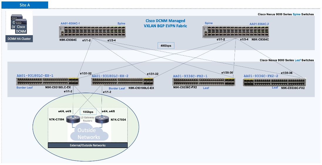
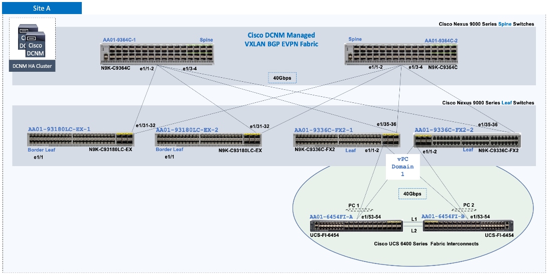
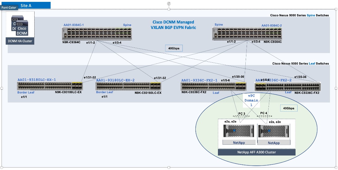
Figure 1 shows the FlexPod VXLAN Single-Site solution components and network connections for a configuration with the Cisco UCS 6454 Fabric Interconnects. This design has port-channeled 25 Gb Ethernet connections between the Cisco UCS 5108 Blade Chassis and the Cisco UCS Fabric Interconnects via the Cisco UCS 2408 Fabric Extenders, port-channeled 25 Gb Ethernet connections between the Cisco UCS C-Series rackmounts and the Cisco UCS Fabric Interconnects, and 100 Gb Ethernet connections between the Cisco UCS Fabric Interconnect and Cisco Nexus 9000 series leaf and spine switches in the fabric, with 40 Gb Ethernet used between the Cisco Nexus 9000 and NetApp AFF A300 storage array. The reference architecture reinforces the "wire-once" strategy, because as additional storage is added to the architecture, no re-cabling is required from the hosts to the Cisco UCS fabric interconnect.
Figure 1. FlexPod with Cisco UCS 6454 Fabric Interconnects and NetApp AFF A300 Series
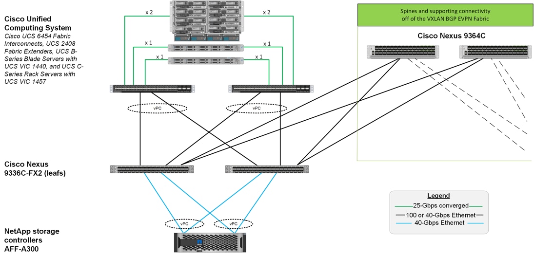
The reference hardware configuration includes:
● Two Cisco Nexus 9336C-FX2 leaf switches
● Two Cisco Nexus 9364C spine switches
● Two Cisco UCS 6454 fabric interconnects
● One NetApp AFF A300 (HA pair) running ONTAP 9.7
Deployment Hardware and Software
Table 1 lists the hardware components and software revisions used for validating this solution.
| Layer |
Device |
Image |
Comments |
| Compute |
Cisco UCS Fabric Interconnects 6454 |
4.1(2a) |
Includes the Cisco UCS Manager and Cisco UCS VIC 1455 |
| Network Fabric |
Cisco Nexus 9364C NX-OS |
9.3(5) |
Spine switches |
|
|
Cisco Nexus 9336C-FX2 NX-OS |
9.3(5) |
Leaf switches |
| Storage |
NetApp AFF A300 |
ONTAP 9.7 |
|
| Software |
Cisco UCS Manager |
4.1(2) |
|
|
|
VMware vSphere |
7.0 |
|
|
|
VMware ESXi nenic Ethernet Driver |
1.0.33.0 |
|
|
|
NetApp Virtual Storage Console (VSC) / VASA Provider Appliance |
9.7.1 |
|
|
|
NetApp SnapCenter for vSphere |
4.3.1 |
Includes SnapCenter Plug-in for VMware vSphere |
|
|
NetApp NFS Plug-in for VMware VAAI |
1.1.2-3 |
|
|
|
NetApp Active IQ Unified Manager |
9.7P1 |
|
| Management |
Cisco Intersight |
N/A |
|
|
|
Cisco Data Center Network Manager (LAN Fabric) |
11.4(1) |
|
|
|
NetApp Active IQ |
N/A |
|
This document explains how to configure a fully redundant, highly available configuration for a FlexPod unit with ONTAP storage. Therefore, reference is made to which component is being configured with each step, either 01 or 02 or A and B. For example, node01 and node02 are used to identify the two NetApp storage controllers that are provisioned with this document, and Cisco Nexus A or Cisco Nexus B identifies the pair of Cisco Nexus switches that are configured. The Cisco UCS Fabric Interconnects are similarly configured. Additionally, this document details the steps for provisioning multiple Cisco UCS hosts, and these examples are identified as: VM-Host-Infra-01, VM-Host-Infra-02 to represent infrastructure hosts deployed to each of the fabric interconnects in this document. Finally, to indicate that you should include information pertinent to your environment in a given step, <text> appears as part of the command structure. See the following example for the network port vlan create command:
Usage:
network port vlan create ?
[-node] <nodename> Node
{ [-vlan-name] {<netport>|<ifgrp>} VLAN Name
| -port {<netport>|<ifgrp>} Associated Network Port
[-vlan-id] <integer> } Network Switch VLAN Identifier
Example:
network port vlan create -node <node01> -vlan-name a0a-<vlan id>
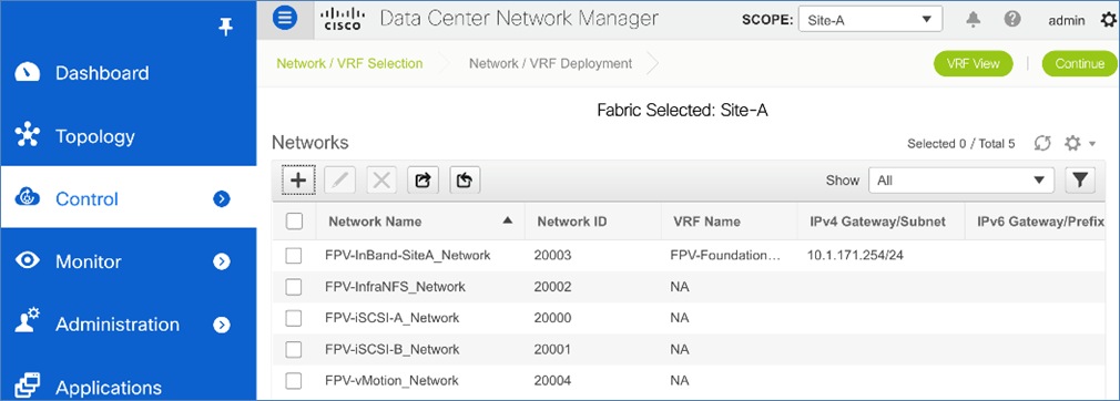
This document is intended to enable you to fully configure the customer environment. In this process, various steps require you to insert customer-specific naming conventions, IP addresses, and VLAN schemes, as well as to record appropriate MAC addresses. Table 2 lists the VLANs necessary for deployment as outlined in this guide.
| VLAN Name |
VLAN Purpose |
ID used in Validating this Document |
| Out-of-Band Mgmt |
Out-of-band management interfaces |
163 |
| Site1-IB |
In-band management interfaces |
122 |
| Common-Services |
Example network for shared resources, used by vCenter and AD in this design |
322 |
| Native |
untagged frames are assigned |
2 |
| iSCSI-A |
iSCSI A traffic |
3010 |
| iSCSI-B |
iSCSI B traffic |
3020 |
| Infra-NFS |
Infrastructure NFS traffic |
3050 |
| vMotion |
VMware vMotion |
3000 |
| VM-Traffic-1 |
Production VM Interfaces |
1001 |
| VM-Traffic-2 |
Production VM Interfaces |
1002 |
| VM-Traffic-3 |
Production VM Interfaces |
1003 |
The information in this section is provided as a reference for cabling the physical equipment in a FlexPod environment. To simplify cabling requirements, a cabling diagram was used.
The cabling diagram in this section contains details for the prescribed and supported configuration of the NetApp AFF 300 running NetApp ONTAP® 9.7.
![]() For any modifications of this prescribed architecture, consult the NetApp Interoperability Matrix Tool (IMT).
For any modifications of this prescribed architecture, consult the NetApp Interoperability Matrix Tool (IMT).
This document assumes that out-of-band management ports are plugged into an existing management infrastructure at the deployment site. These interfaces will be used in various configuration steps.
![]() Be sure to use the cabling directions in this section as a guide.
Be sure to use the cabling directions in this section as a guide.
The NetApp storage controller and disk shelves should be connected according to best practices for the specific storage controller and disk shelves. For disk shelf cabling, refer to NetApp Support.
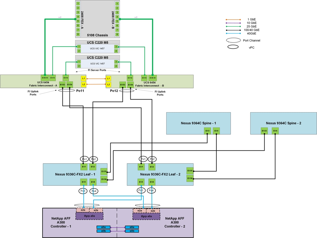
Figure 2 details the cable connections used in the validation lab for the FlexPod topology based on the Cisco UCS 6454 fabric interconnect. 40/100Gb links connect the Cisco UCS Fabric Interconnects to and within the VXLAN fabric of the Cisco Nexus Switches, and 40Gb links connect the NetApp AFF controllers to the Cisco Nexus Switches. Additional 1Gb management connections will be needed for an out-of-band network switch that sits apart from the FlexPod infrastructure. Each Cisco UCS fabric interconnect and Cisco Nexus switch is connected to the out-of-band network switch, and each AFF controller has a connection to the out-of-band network switch. Layer 3 network connectivity is required between the Out-of-Band (OOB) and In-Band (Site1-IB) Management Subnets.
Figure 2. FlexPod Cabling with Cisco UCS 6454 Fabric Interconnect
Solution Deployment - Network Fabric
This section provides a detailed step-by-step procedure for deploying a Cisco VXLAN BGP EVPN fabric to enable network connectivity between FlexPod storage, compute, and other components in the solution. The VXLAN fabric in this solution will deployed and managed by a Cisco Data Center Network Manager (Cisco DCNM). The network fabric will consist of single data center site with different models of Cisco Nexus spine and leaf switches. The network fabric used in this solution consists of a one pair of spine switches and two pairs of leaf switches. The Cisco UCS domains and NetApp storage arrays will connect to same leaf switch pair in this design. The other leaf switch pair in the design serve as Border leaf switch for connectivity outside the fabric. The separate leaf switch pairs for each role (access/TOR vs. border) ensures a scalable VXLAN fabric.
![]() This design assumes a greenfield deployment of the VXLAN BGP EVPN fabric. Customers with an existing VXLAN fabric can use portions of the deployment discussed in this section to add new switches or align with this FlexPod design.
This design assumes a greenfield deployment of the VXLAN BGP EVPN fabric. Customers with an existing VXLAN fabric can use portions of the deployment discussed in this section to add new switches or align with this FlexPod design.
Deployment Overview
A high-level overview of the steps involved in deploying a single-site network fabric is provided below.
● Physical Connectivity: Complete the physical connectivity as outlined in the FlexPod Cabling section.
● Cisco Nexus Switches - Base Setup and Configuration: Bring-up Cisco Nexus switches with a minimal version of software that supports Cisco DCNM and VXLAN EVPN fabric and perform minimal setup and configuration so that they can be imported into the fabric by Cisco DCNM. The minimal configuration includes setting the Hostname, OOB Management IP and Gateway, Admin account and password, and setting boot variable for booting a valid image. The base setup and configuration is outside the scope of this document - please see relevant Nexus product documentation for how this can be done.
● Out-of-Band (OOB) Management Connectivity: Complete all the out-of-band management connectivity for the spine and leaf switches in the network fabric. Enabling OOB connectivity is outside the scope of this document - see relevant Nexus product documentation for setting this up.
● Deploy Cisco DCNM: Deploy Cisco DCNM LAN Fabric and enable OOB management connectivity to the spine and leaf switches in the fabric. Cisco DCNM will discover the switches, deploy the VXLAN BGP EVPN fabric and provide a centralized management portal for day-2 operation and management of the fabric. Deployment of Cisco DCNM is also outside the scope of this document – see Cisco DCNM 11.4(1) documentation on cisco.com for additional details.
● Licensing: Procure necessary licensing for Cisco DCNM and Nexus switches and configure the licenses before the available grace-period expires to fully utilize all services provided by this Cisco environment.
● Deploy VXLAN BGP EVPN Fabric using Cisco DCNM: Cisco DCNM’s Fabric Builder is used to configure and deploy the VXLAN BGP EVPN fabric in Site-A. To deploy the fabric configuration to the switches, the spine and leaf switches must be first discovered and added to Cisco DCNM. Cisco DCNM can will then deploy the IP underlay and VXLAN overlay across all the switches that make up the data center fabric in Site-A.
● External or Outside Connectivity: Enable connectivity from VXLAN fabric in Site-A to outside networks. In this design, these are any networks that are outside the VXLAN fabric in Site-A – they can be either internal or external to the Enterprise. In this design, this connectivity enabled reachability to key services hosted outside the fabric such as Microsoft Active Directory, DNS within the Enterprise, and services outside the Enterprise such as Cisco Intersight and Cisco Umbrella in the public cloud.
● Access Layer Connectivity to NetApp Storage Cluster: Enable access-layer connectivity from the VXLAN fabric in Site-A to the NetApp Storage infrastructure in the solution. The NetApp storage infrastructure in this solution consists of an AFF A300 storage array.
● Access Layer Connectivity to Cisco UCS Domain: Enable access-layer connectivity from the VXLAN fabric in Site-A to the Cisco UCS infrastructure in the solution. The Cisco UCS infrastructure in this solution consists of a pair of Cisco UCS Fabric Interconnects that connect to Cisco UCS B-series and C-series servers.
● FlexPod Infrastructure Connectivity: A dedicated tenant is defined in this design to enable the infrastructure connectivity in the FlexPod VSI solution. A FlexPod Foundation Tenant is configured to enable connectivity for FlexPod Compute and Storage infrastructure. In this design, the Foundation tenant will provide infrastructure connectivity to enable the FlexPod Virtual Server Infrastructure (VSI). This tenant is not used for applications workloads hosted on the FlexPod VSI, though it is used by management components such as VMware vCenter, NetApp VSC and so on. that is used to manage and operate the FlexPod VSI.
● On-board multi-tier applications: A separate application tenant is defined in the VXLAN fabric to meet the connectivity needs of the applications hosted on the FlexPod VSI. Expanded tenant separation is possible within Cisco UCS and NetApp storage, but is not discussed in depth within this design.
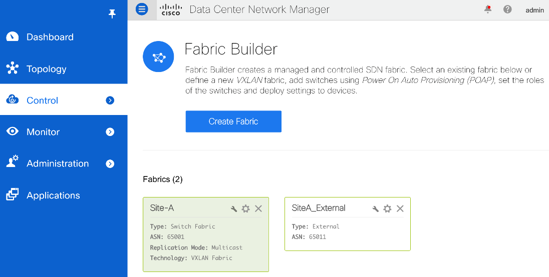
Deploy VXLAN BGP EVPN Fabric using Cisco DCNM
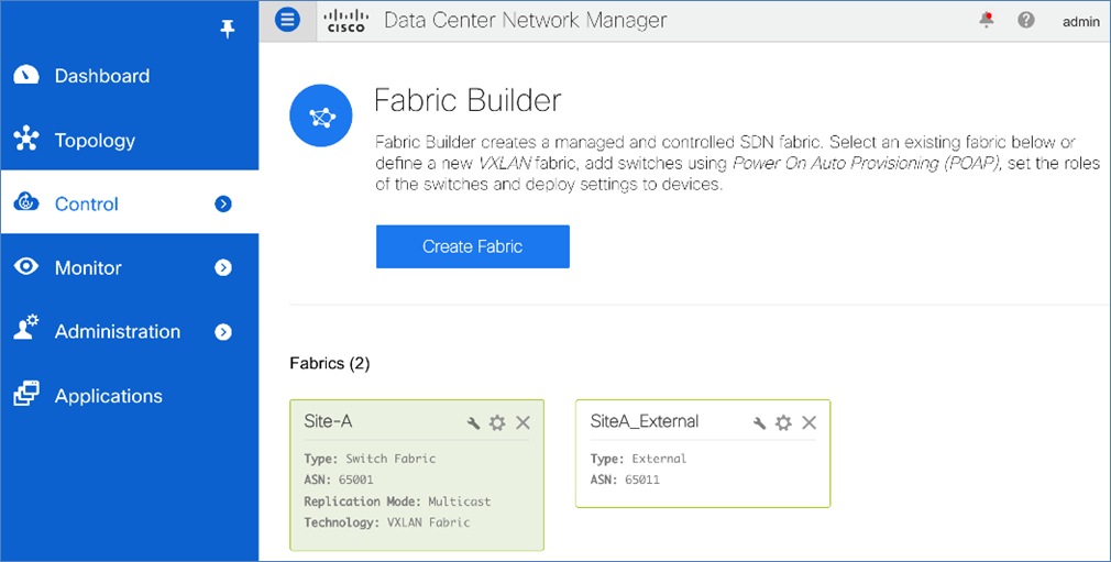
This section uses Cisco DCNM’s LAN Fabric Builder to configure and deploy a VXLAN BGP EVPN fabric in Site-A (or Site-1). The LAN Fabric Builder in Cisco DCNM creates and manages a software-defined (SDN) fabric by selecting an existing fabric or by defining a new VXLAN fabric. The switches can be discovered and added to the fabric using Power On Auto Provisioning (POAP), or by directly importing switches (with a base configuration). You can then set the roles of the switches, pre-select the fabric settings, and then use one-click Save & Deploy to deploy the configuration and bring up a fully functional VXLAN BGP EVPN fabric that spans any number of spine and leaf switches.
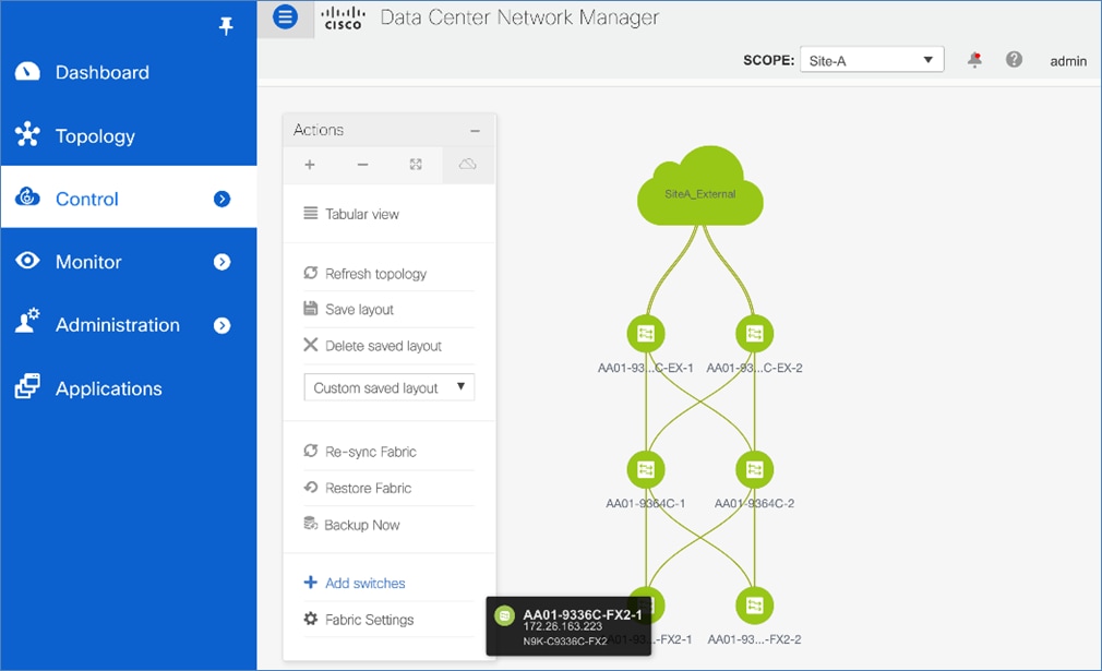
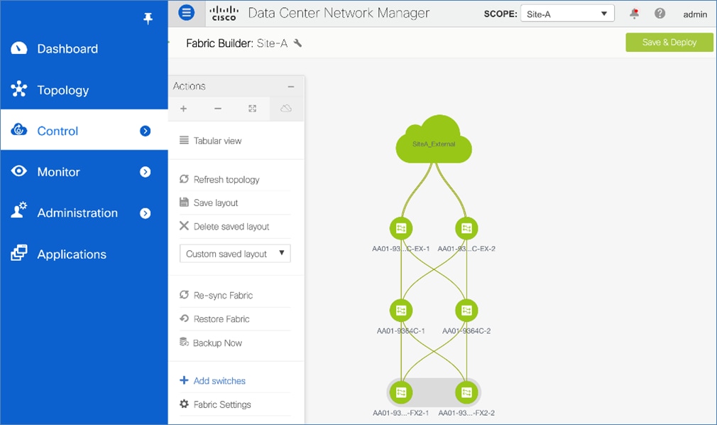
Topology
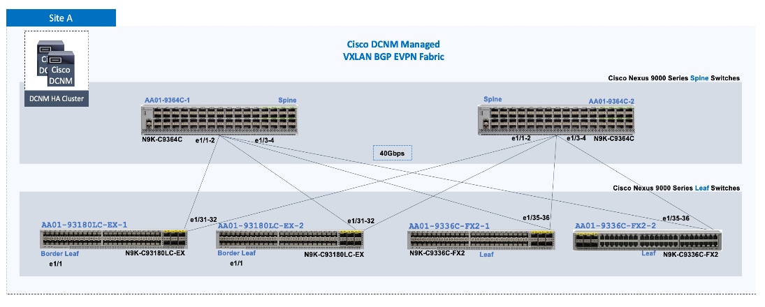
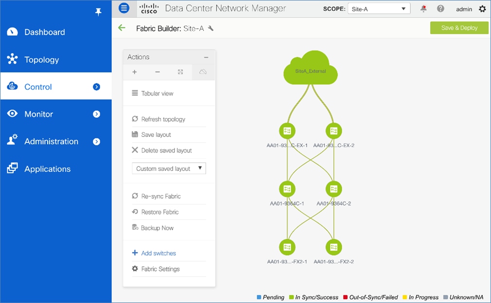
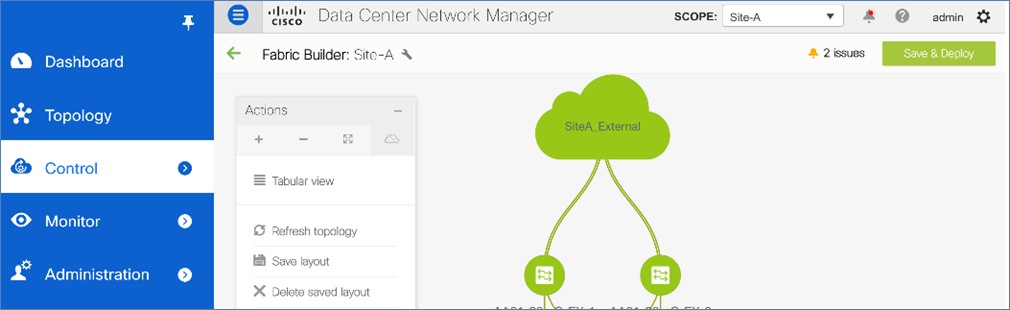
Topology figure above shows the connectivity of the Cisco Nexus 9364C Spines and Cisco Nexus 9336C-FX2 Leafs in the validation. Also pictured is the connection to a pair of Cisco Nexus 93180LC-EX Leafs that are used as border leaf switches for connectivity outside of the fabric.
The VXLAN BGP EVPN fabric configuration settings used for deploying the Site-A data center fabric is provided in the table below.
Table 3. Fabric Configuration Information – Site-A
| Data Center |
Parameters |
Default Parameters |
Notes |
| Fabric Name |
Site-A |
_ |
|
| Fabric Template |
Easy_Fabric_11_1 |
_ |
|
| General Tab |
|||
| BGP ASN |
65001 |
_ |
|
| NX-OS Software Image |
9.3(5) |
_ |
Optional (If Set, Image Version Check Enforced On All Switches. Images can be uploaded by going to Control > Image Upload) |
| Protocols Tab |
|||
| Underlay Routing Protocol Tag |
Site-A_UNDERLAY |
UNDERLAY |
|
| Resources Tab |
|||
| Underlay Routing Loopback IP |
10.11.0.0/24 |
10.2.0.0/22 |
Optional (Default Values can be used as-is) |
| Underlay VTEP Loopback IP Range |
10.11.1.0/24 |
10.3.0.0/22 |
Optional (Default Values can be used as-is) |
| Underlay RP Loopback IP Range |
10.11.254.0/24 |
10.254.254.0/24 |
Optional (Default Values can be used as-is) |
| Underlay Subnet IP Range |
10.11.3.0/22 |
10.4.0.0/16 |
Optional (Default Values can be used as-is) |
| Layer 2 VXLAN VNI Range |
20000-24999 |
30000-49000 |
Optional (Default Values can be used as-is) |
| Layer 3 VXLAN VNI Range |
30000-34999 |
50000-59000 |
Optional (Default Values can be used as-is) |
| Network VLAN Range |
3000-3499 |
2300-2999 |
Optional (Default Values can be used as-is) |
| VRF VLAN Range |
3500-3967 |
2000-2299 |
Optional (Default Values can be used as-is) |
| VRF Lite Deployment |
ToExternalOnly |
Manual |
Optional (Default Values can be used as-is) |
| Auto Deploy Both |
|
|
Optional (Default Values can be used as-is) |
| VRF Lite Subnet IP Range |
10.11.99.0/24 |
10.33.0.0/16 |
Optional (Default Values can be used as-is) |
| VRF Lite Subnet Mask |
30 |
30 |
Optional (Default Values can be used as-is) |
| Service Network VLAN Range |
1500-1599 |
3000-3199 |
Optional (Default Values can be used as-is) |
| Manageability Tab |
|||
| NTP Server IPs |
172.26.163.254 |
_ |
Optional |
| NTP Server VRFs |
management |
_ |
Optional |
| Configuration Backup Tab |
|||
| Hourly Fabric Backup |
|
|
Optional |
The setup information for discovering the spine and leaf switches in the Site-A datacenter fabric is provided in the table below. Cisco DCNM also supports discovery and importing of fabric switches through Power-on-Auto-Provisioning(POAP) – however, POAP was not utilized in this CVD.
Table 4. Discovery Information – Site-A
| Hostname |
Switch Role |
IP Address (OOB) |
Notes |
| AA01-9364C-1 |
Spine |
172.26.163.231/24 |
|
| AA01-9364C-2 |
Spine |
172.26.163.232/24 |
|
| AA01-9336C-FX2-1 |
Leaf |
172.26.163.223/24 |
Top-of-Rack (TOR) switch for access layer connectivity to Cisco UCS compute and NetApp storage |
| AA01-9336C-FX2-2 |
Leaf |
172.26.163.224/24 |
Top-of-Rack (TOR) switch for access layer connectivity to Cisco UCS compute and NetApp storage |
| AA01-93180LC-EX-1-1 |
Border Leaf |
172.26.163.221/24 |
|
| AA01-93180LC-EX-1-2 |
Border Leaf |
172.26.163.222/24 |
|
![]() The devices used in this design were pre-configured with a Hostname, Management IP address, username, password, and boot variable.
The devices used in this design were pre-configured with a Hostname, Management IP address, username, password, and boot variable.
Create VXLAN Data Center Fabric in Site-A
To create the VXLAN BGP EVPN datacenter fabric in Site-A, go to the Setup Information section to follow these steps:
1. Use a browser to navigate to Cisco DCNM’s GUI. Log in using an administrator account with full access to the data center.
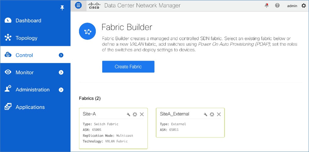
2. From the right window pane, select and click the Fabric Builder icon.
3. From the right window pane, click the Create Fabric icon.
4. In the Add Fabric pop-up window, specify a Fabric Name and select the Fabric Template specified in Table 3 above from the drop-down list.
5. The pop-up window will now expand to include multiple tabs for configuring the fabric. In the General tab, specify the BGP ASN information for Site-A and NX-OS Software Image Version (Optional) from the drop-down list.
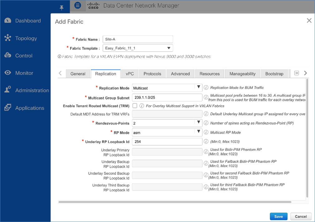
6. In the Replication tab, leave everything as-is. Alternatively, you can customize the default options selected by Cisco DCNM for Replication Mode, Multicast Group Subnet, Rendezvous-Points (RP), RP mode and other settings as needed.
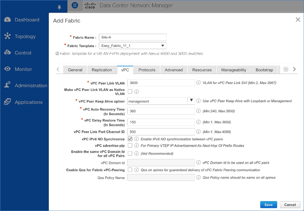
7. In the vPC tab, leave everything as-is. Alternatively, you can customize the selected default options and other settings as needed.
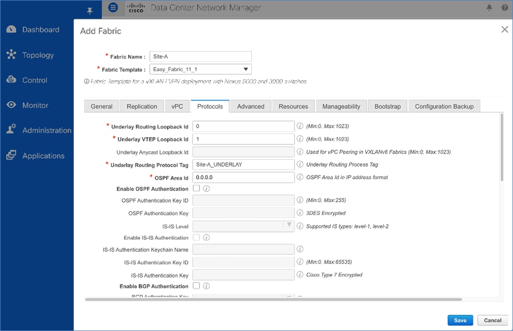
8. In the Protocols tab, specify the Underlay Routing Protocol Tag for Site-A. Leave everything else as-is. Alternatively, you can enable OSPF, ISIS and/or BGP authentication for additional security, enable Bi-directional Forward Detection (BFD) for quicker notification of failures to upper layer protocols such as BGP, OSPF, PIM and so on. You can also add additional customization for the iBGP configuration using the free-form templates provided at the bottom.
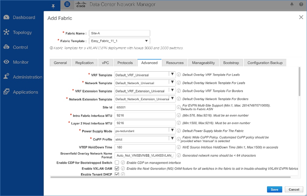
9. In the Advanced tab, leave everything as-is. Alternatively, you can customize the selected default options and other settings as needed. Note that the Site Id matches the BGP ASN specified in the General tab. Also, the Interface MTU is pre-configured to use a jumbo MTU of 9216 across all fabric links and on interfaces connecting to endpoints.
10. (Optional) In this deployment, the Greenfield Cleanup Option is changed from the default of Disable to Enable in order to speed up deployment in the Cisco lab – however, Cisco recommends that customers use the default option that will reload the switches during clean up in Greenfield deployments.
11. (Optional) Customers can also enable PTP and Queueing on core facing interfaces as needed. Note this was not setup in this CVD. PTP is necessary when using Nexus operational tools such as Network Insights – Resources for a more precise and accurate timing of flows in the range of microseconds or nanoseconds.

12. (Optional) Cisco DCNM also allows for Freeform configurations that customers can use for additional configuration parameters as shown below.
13. (Optional) In the Resources tab, you can specify the underlay loopbacks and subnets for various protocols. Cisco DCNM provides default values for these that can be used as-is. However, in this CVD, the parameters specified in the Setup Information section is used. Skip this step if using the default values. Otherwise, configure the Underlay Routing Loopback IP Range, Underlay VTEP Loopback IP Range, Underlay RP Loopback IP Range and Underlay Subnet IP Range for Site-A using the setup information.
14. (Optional) In the Resources tab, you can specify the VXLAN Network IDs (VNID) and VLAN ranges for the access layer networks. Cisco DCNM provides default values for these that can be used as-is. However, in this CVD, the parameters specified in the Setup Information section is used. Skip this step if using the default values. Otherwise, configure the Layer 2 VXLAN VNI Range, Layer 3 VXLAN VNI Range, Network VLAN Range, VRF VLAN Range and Service Network VLAN Range for Site-A using the setup information.
![]() The other parameters, namely VRF Lite Deployment, Auto Deploy Both, VRF Lite Subnet IP Range, and VRF Lite Subnet Mask can be specified now or can be updated in the External or Outside Connectivity section where they are used.
The other parameters, namely VRF Lite Deployment, Auto Deploy Both, VRF Lite Subnet IP Range, and VRF Lite Subnet Mask can be specified now or can be updated in the External or Outside Connectivity section where they are used.
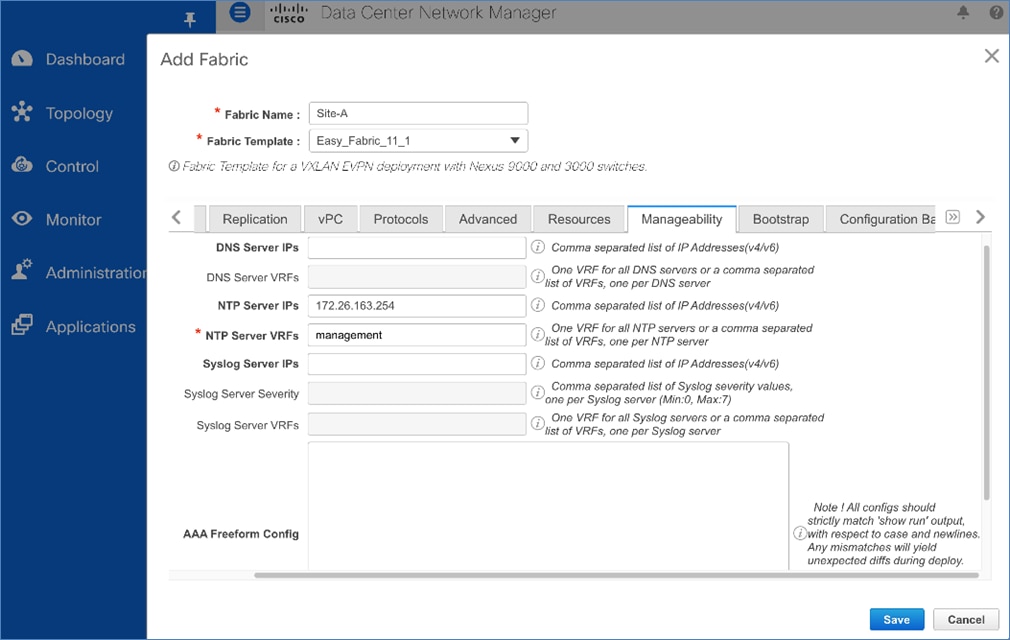
15. (Optional) In the Manageability tab, specify the NTP server and VRF for accessing the NTP servers. Other network infrastructure services such as DNS and Syslog servers can also be specified here.
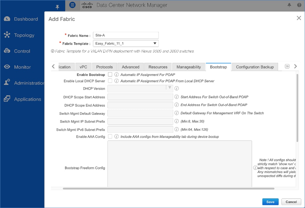
16. (Optional) In the Bootstrap tab, customers can specify bootstrap information if POAP is used to discover and import the switches into the fabric. This was not used in this CVD – proceed to the next tab.
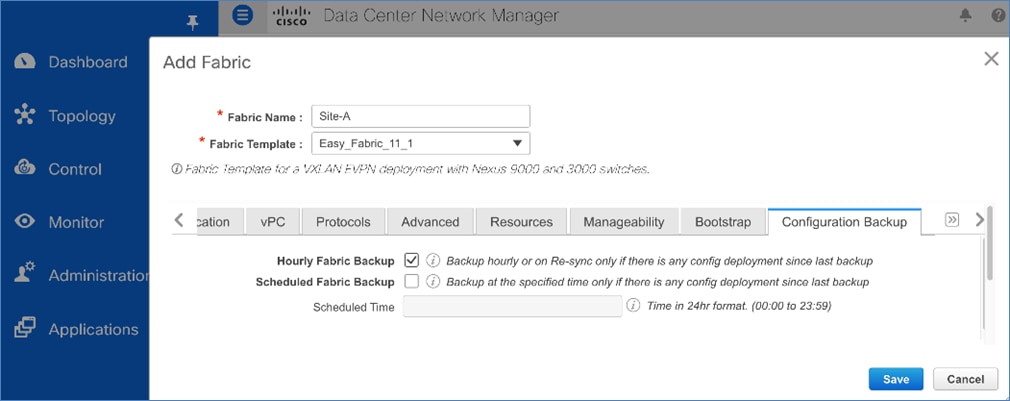
17. (Optional) In the Configuration Backup tab, specify a backup schedule for the fabric as shown below.
18. Click Save to save the fabric settings for the VXLAN Fabric in Site-A. You will get a pop-up on the right-bottom corner saying the Fabric was deployed successfully if the settings were saved. The saved settings are merely the configuration intent at this stage – they will need to be deployed on the switches for it to take effect.
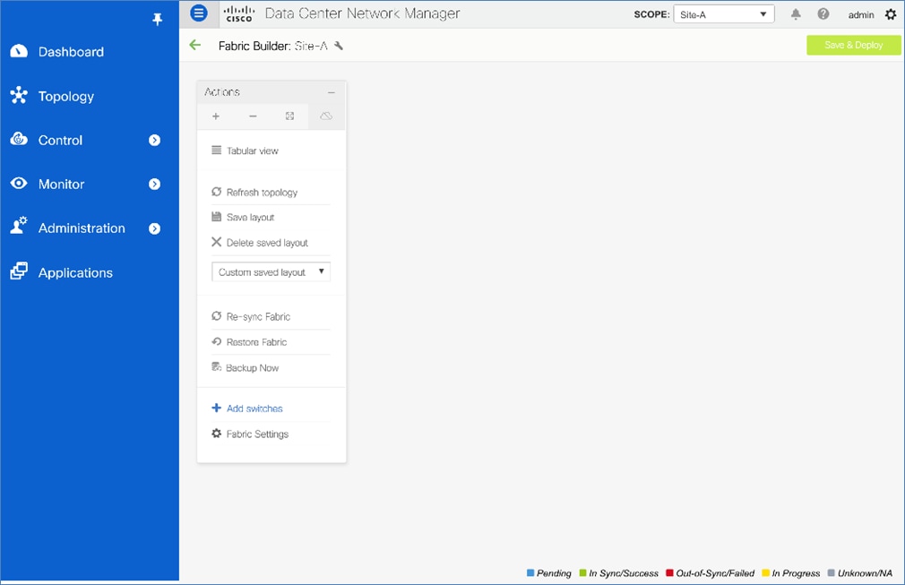
19. At this point, you can start adding switches to the VXLAN fabric. Note that you can use ![]() Fabric Settings in the Actions menu at any time to modify the parameters – however, once switches have been added to the fabric, you will need to do a Save & Deploy (top-right corner) in order to save the settings and then to apply them to the switches in the fabric.
Fabric Settings in the Actions menu at any time to modify the parameters – however, once switches have been added to the fabric, you will need to do a Save & Deploy (top-right corner) in order to save the settings and then to apply them to the switches in the fabric.
20. Proceed to the next section to discover and add switches to the Site-A datacenter fabric.
![]() Always verify scope (for example, SCOPE: Site-A ) in the top-right corner of the window when making changes or viewing the status to ensure that you are in the corrects datacenter or view.
Always verify scope (for example, SCOPE: Site-A ) in the top-right corner of the window when making changes or viewing the status to ensure that you are in the corrects datacenter or view.
Add Spine and Leaf switches to the VXLAN Fabric
As stated earlier, this design assumes a greenfield deployment where the fabric is built from the ground-up. Therefore, this section walks through the discovery, addition, and initial configuration of all switches to the Site-A fabric. For existing fabrics, customers can use relevant portions of this section to add switches to their fabric.
To add spine and leaf switches to the VXLAN fabric, follow these steps:
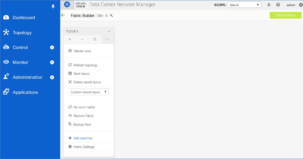
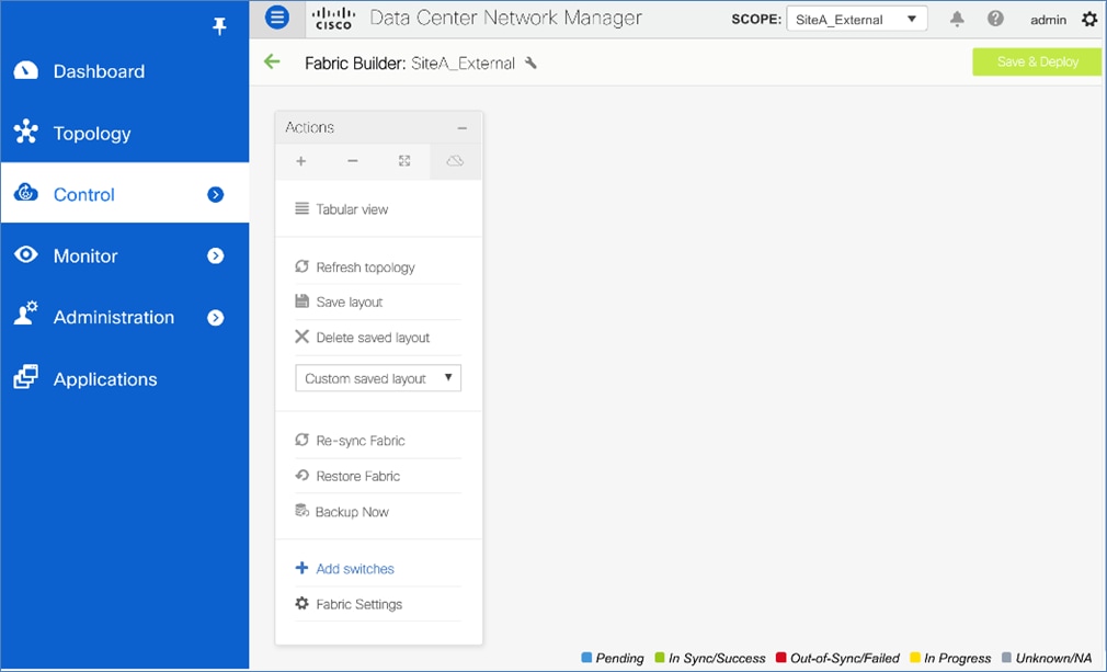
1. In the right-window pane, verify that the SCOPE: is Site-A in the drop-down list near the top-right corner. From the Actions menu, select and click Add Switches.
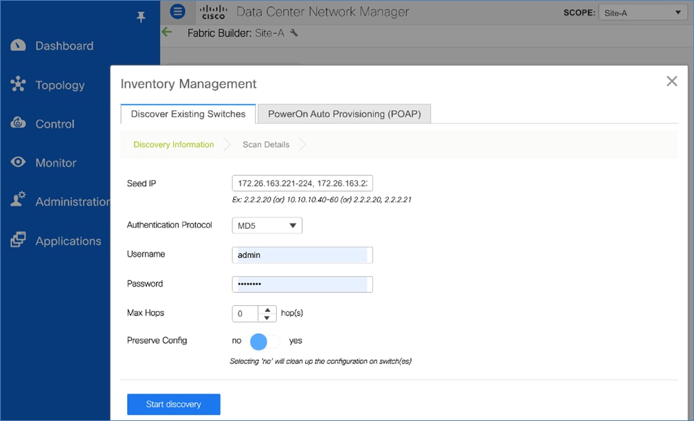
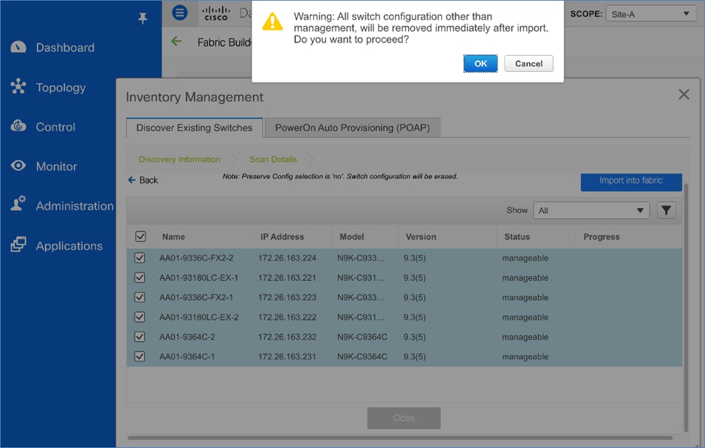
2. In the Inventory Management pop-up window, select the Discover Existing Switches tab. Note that you can also POAP on Cisco DCNM to discover and add switches to the VXLAN fabric. For the Seed IP, specify the IP address range of all switches that need to be discovered. For the Username and Password, specify the administrator username and password for the switches that you can use to log-on to the switches. For the Max Hops, specify ‘0’ otherwise the discovery may take a long time to complete. For Preserve Config, select ‘no’ to clean up the configuration on the switches before adding them to the fabric.
![]() The configuration on the switches are cleaned up before adding the switches as this CVD assumes a greenfield deployment. Cleaning up ensures there are no conflicts between the configuration deployed by Cisco DCNM and what is actually configured on the switch.
The configuration on the switches are cleaned up before adding the switches as this CVD assumes a greenfield deployment. Cleaning up ensures there are no conflicts between the configuration deployed by Cisco DCNM and what is actually configured on the switch.
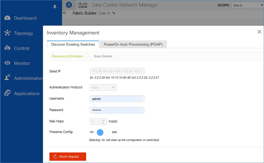
3. Click the Start discovery button at the bottom to start the discovery process. You should see a spinning wheel in the red Abort Request button at the bottom as Cisco DCNM attempts to discover and find these switches.
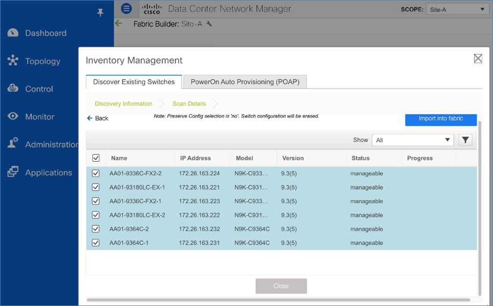
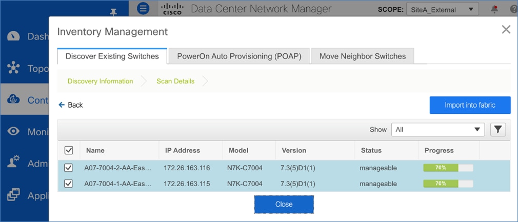
4. Once the discovery completes, you will be provided with a list of switches that can be imported into the fabric. Use the checkboxes to the left of the switches to select the relevant switches. In this case, all switches in the list are selected using the checkbox to the left of the Name column. Click Import into fabric.
5. Click OK in the Warning message that pops-up to confirm removal and cleanup of all configuration on the switches except for management connectivity.
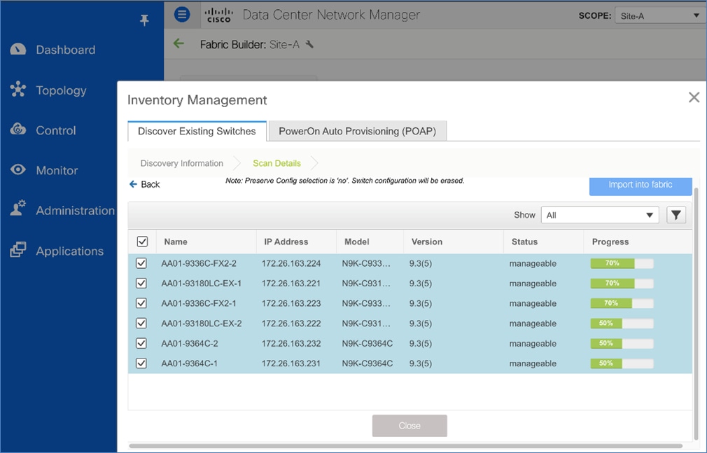
6. You can view the progress of the import in the Progress column for each switch being imported.
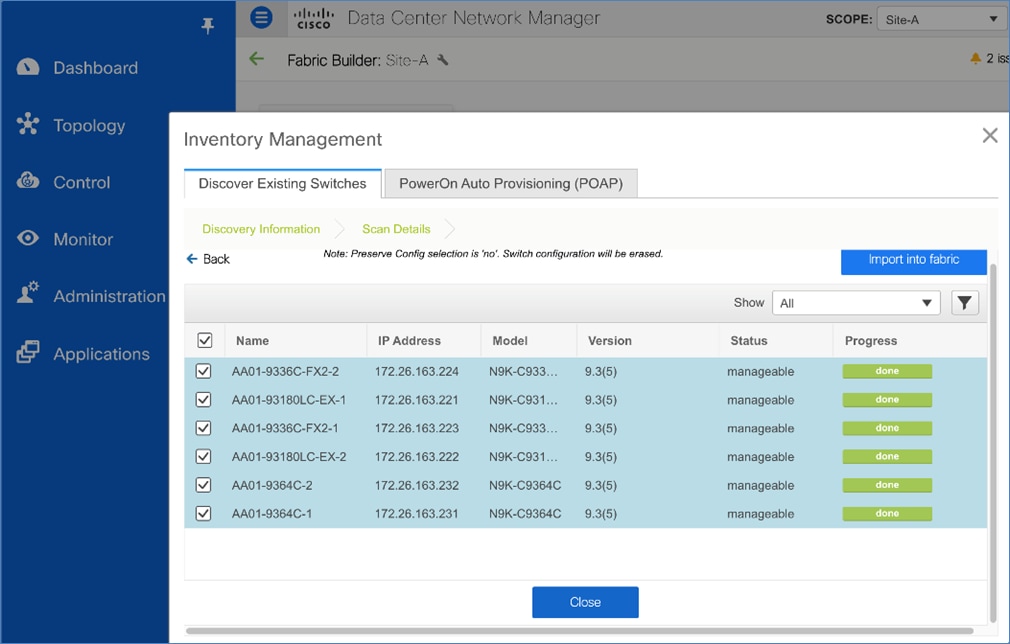
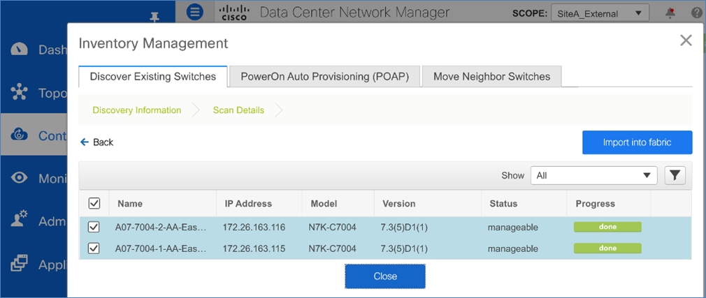
7. Once imported is complete, the Progress column will show done. Click Close
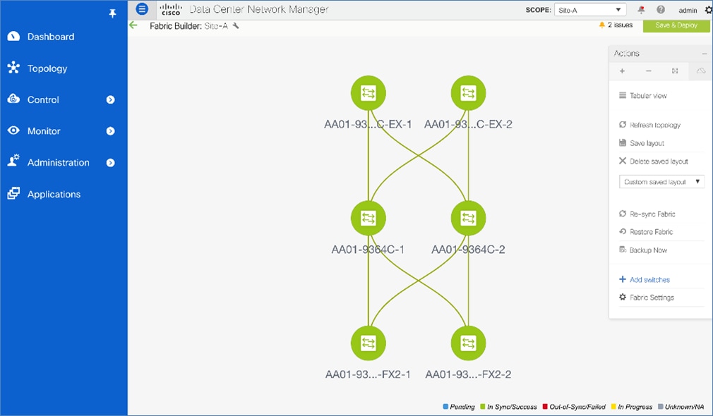
8. You should now see the topology as shown below. Move the Actions menu/window to right-side for a better view of the topology.
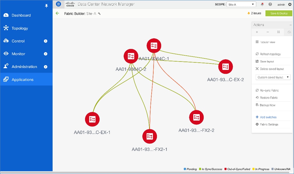
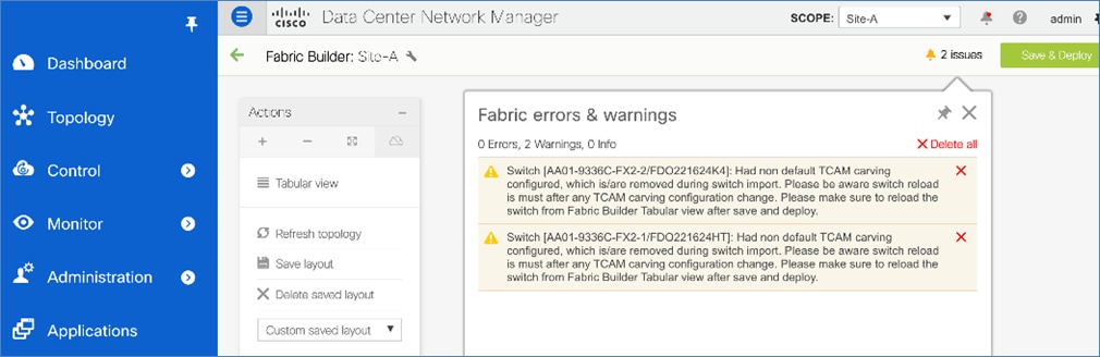
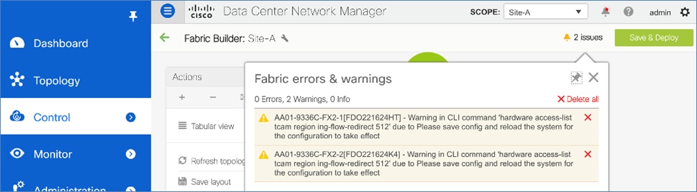
9. At this stage, all switches in the topology should be red to indicate they are in Out-of-Sync/Failed state. This is to be expected as the configuration on the switches (which have been wiped clean) do not match the Fabric Settings or the fabric configuration on Cisco DCNM. Also note that there may warnings or errors that show up, if any exist, it will show up to the left of the Save & Deploy button. Review the issues so they can be resolved. In this case, there are 2 issues Warnings. The Fabric errors are warnings and indicate that a reload of two of the switches should be done after a Save & Deploy. We will therefore wait on resolving these until after a Save & Deploy is done.
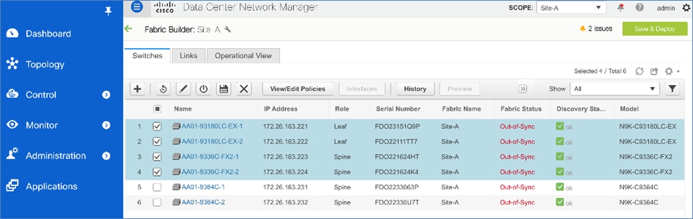
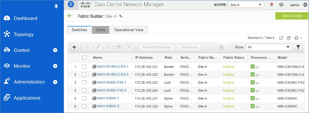
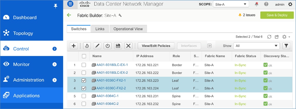
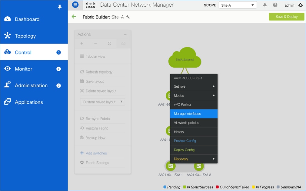
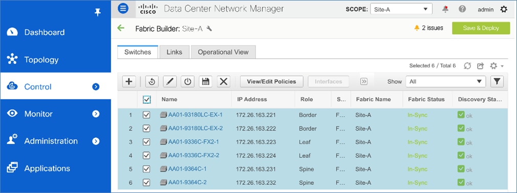
10. From the Actions menu/window, select Tabular view. Verify that the Discovery Status is ok. For each switch, verify that Role is correct. Modify the role as needed. The role of 4 switches selected below needs to be changed. To change the role, go back to the topology view by clicking on the green left arrow in the top left corner of the right window pane.
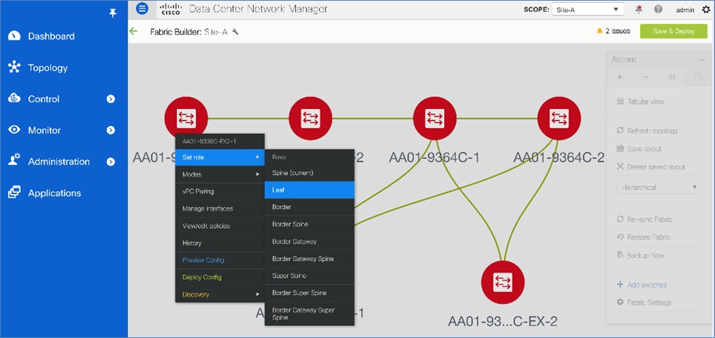
11. In the topology view, from the Actions menu/window, select Hierarchical from the drop-down list. To change the role, select the switch and right-click to select Set role and then select the correct role for the switch from the list. A small window on the bottom right will pop-up to indicate with role change was successful.
12. Repeat the previous step for all switches whose role needs to be changed.
13. Verify the roles have been changed, go back Tabular view from the Actions menu/window, and verify the Role column for each switch.
14. Go back to Topology view, from the Actions menu/window, select Hierarchical from the drop-down list. The topology view should now change based on the role of the devices. Select Save layout from the Actions menu.
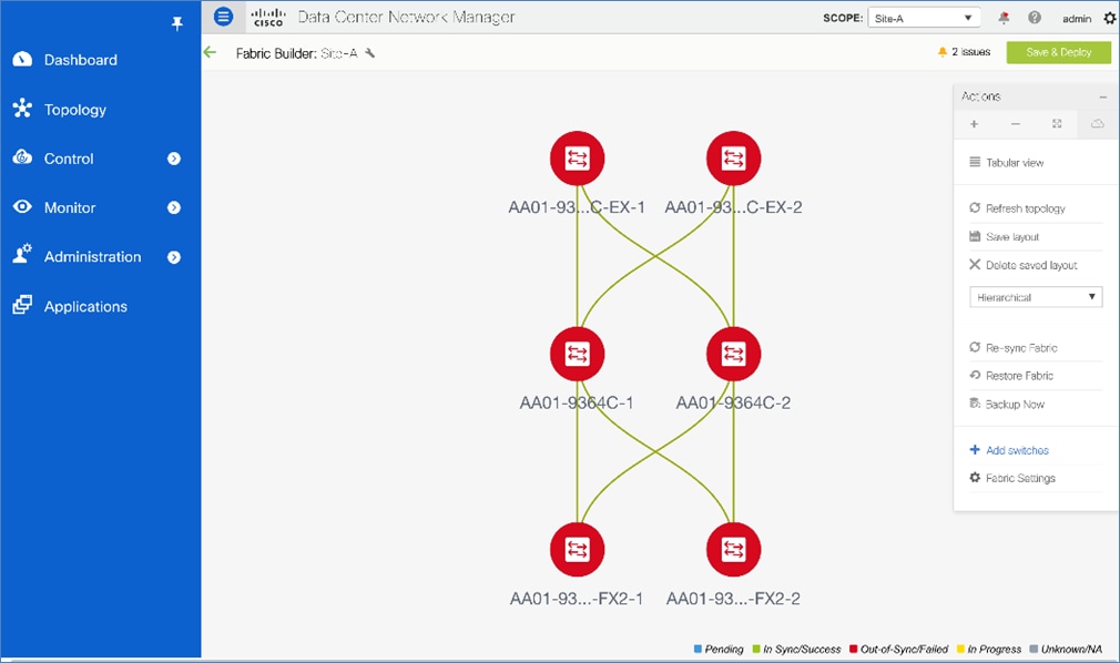
15. You are now ready to deploy the configuration to the switches in the fabric. Click Save & Deploy.
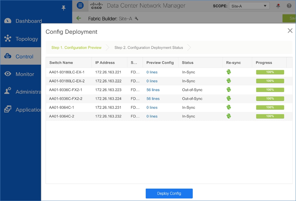
16. In the Config Deployment window, you can see the number of lines of configuration that will be deployed on each switch. The configuration deployed will vary depending on the role of the switch.
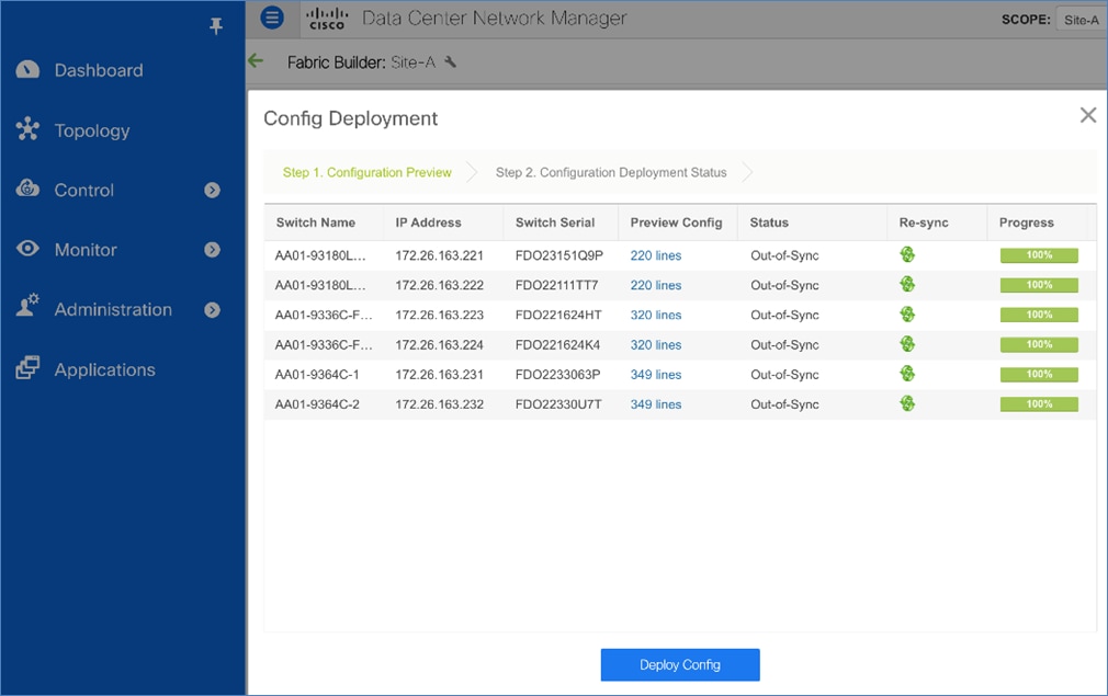
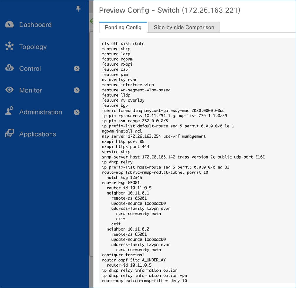
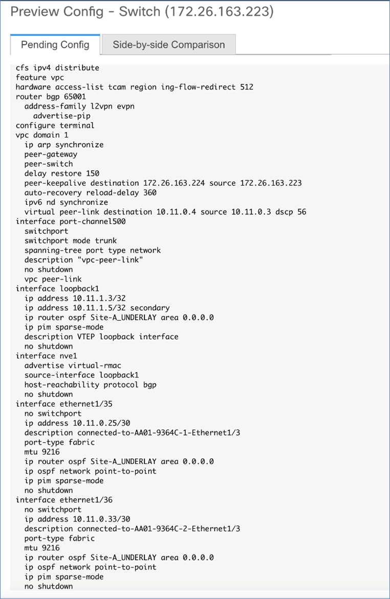
17. You can preview the configuration on each switch by clicking on the number of lines as shown below. In the Preview Config – Switch (IP) pop-up window, you can see the configuration that will be pushed to the switch in question. A partial view of the configuration is shown below.
18. Exit the Preview Config pop-up window and click the Deploy Config button in the Config Deployment window.
19. In the Config Deployment window, you can view the deployment progress as shown below.
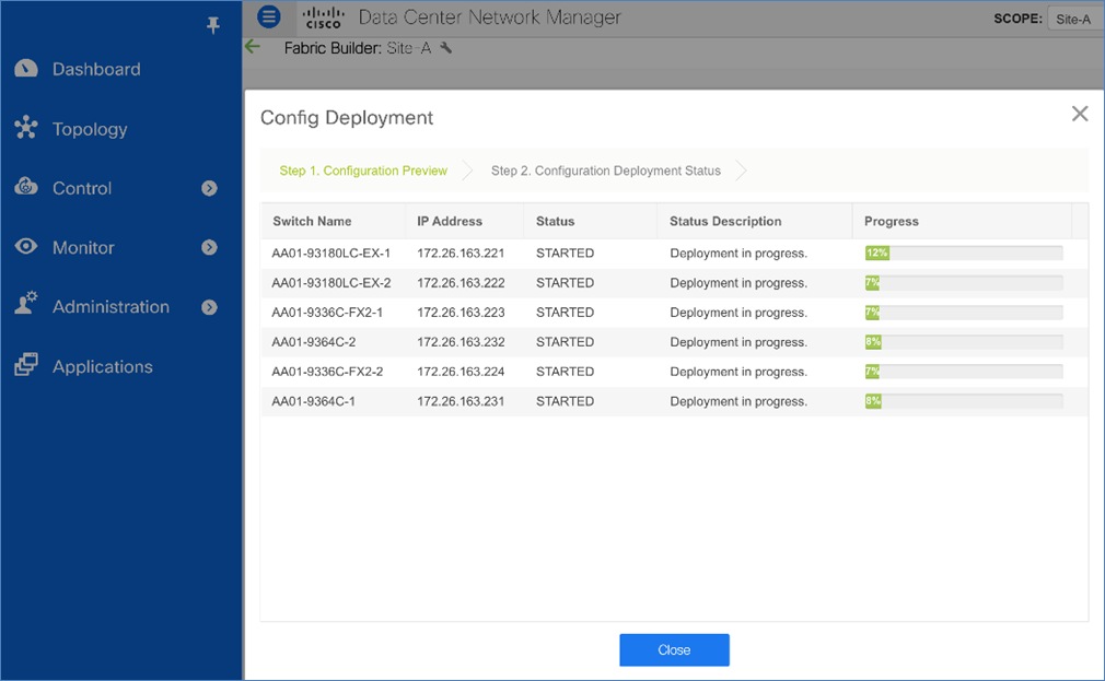
20. The status will show Deployed successfully when complete. Click Close.
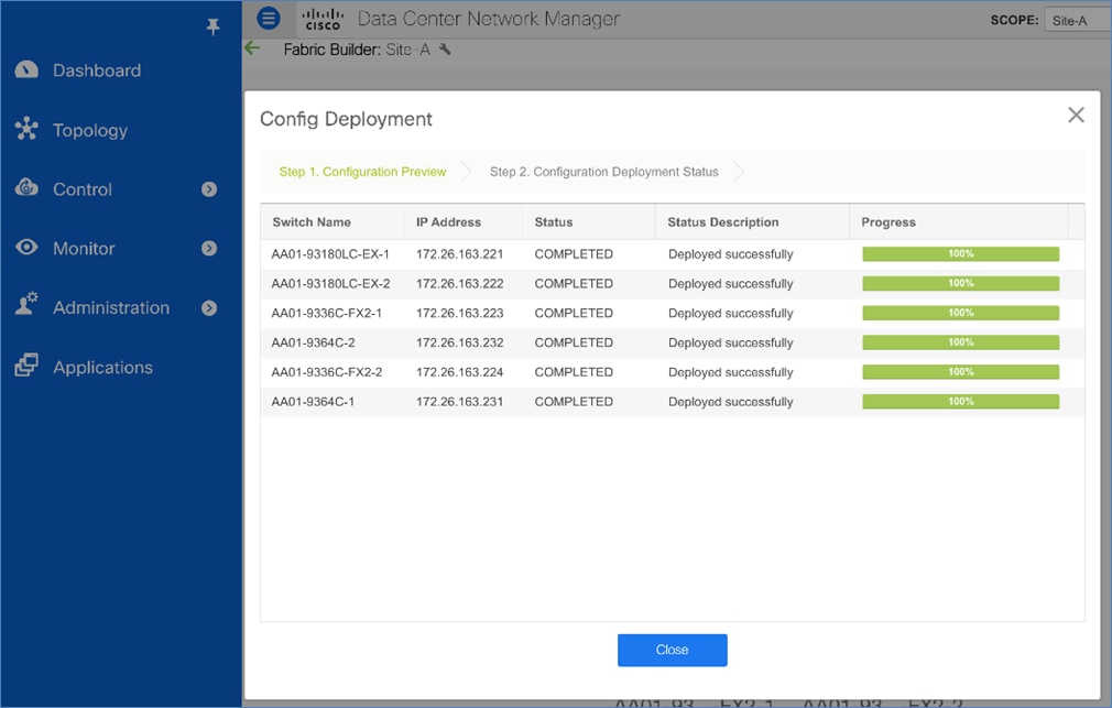
21. The topology view should now show all switches in the green state indicating that the configurations between DCNM and the switches are in sync.
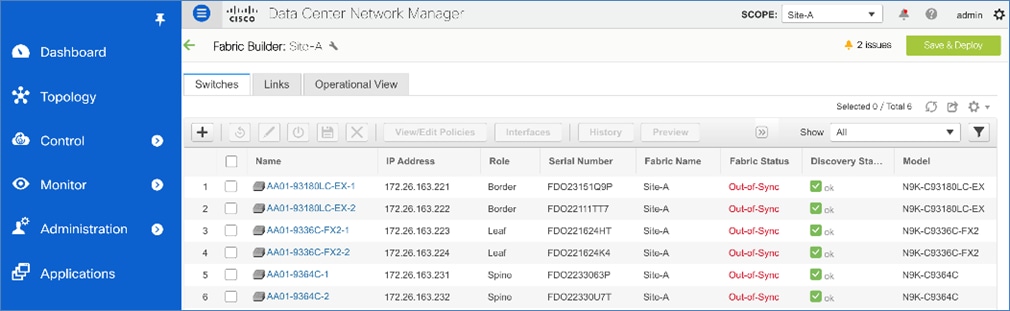
22. From the Actions menu/window, select Tabular view and for each switch, verify the Role and that the Fabric Status is In-Sync.
![]() It is generally a good practice to use
It is generally a good practice to use ![]() Refresh Topology from the Actions menu/window in Topology view to verify the current state of the switches in the fabric especially when making change.
Refresh Topology from the Actions menu/window in Topology view to verify the current state of the switches in the fabric especially when making change.
External or Outside Connectivity
In this design, connectivity outside or external to the VXLAN BGP EVPN fabric is necessary to access critical services in existing infrastructure that are outside the fabric and also to access cloud-based services. In this section, the external connectivity deployed will enable north-south traffic for access services such as Microsoft Active Directory and Domain Name System (DNS)
Topology
![]() The Cisco Nexus 93180LC-EX border leaf switches for external access are positioned as a best practice being apart from the production FlexPod leaf switches in the infrastructure. If port availability and expansion needs are met with just the production leaf switches, this functionality could be combined.
The Cisco Nexus 93180LC-EX border leaf switches for external access are positioned as a best practice being apart from the production FlexPod leaf switches in the infrastructure. If port availability and expansion needs are met with just the production leaf switches, this functionality could be combined.
Setup Information
The configuration parameters required for enabling external or outside connectivity from the Site-A datacenter fabric is provided in the table below.
Table 5. External or Outside Connectivity Parameters – Site-A
| Data Center |
Parameters |
Default Parameters |
Notes |
| Fabric Name |
SiteA_External |
_ |
|
| Fabric Template |
External_Fabric_11_1 |
_ |
|
| General Tab |
|||
| BGP AS# |
65011 |
_ |
|
| Fabric Monitor Mode |
|
|
Optional (If default is used, Cisco DCNM will not configure the external gateways) |
| Advanced Tab |
|||
| Enable AAA IP Authorization |
|
|
Future DCNM releases will use this. |
| Resources Tab |
|||
| Sub-interface Dot1q Range |
1101-1104 |
2-511 |
Optional (Default Values can be used as-is) |
| Underlay Routing Loopback IP |
11.11.11.0/24 |
10.1.0.0/22 |
Optional (Default Values can be used as-is) |
| Configuration Backup Tab |
|||
| Hourly Fabric Backup |
|
|
Optional |
The setup information for discovering the external gateway switches in the outside/external fabric managed by Cisco DCNM is provided in the table below. Cisco DCNM also supports discovery and importing of external switches through Power-on-Auto-Provisioning(POAP) – however, POAP was not utilized in this CVD.
Table 6. Discovery Information – SiteA_External
| Hostname |
Switch Role |
IP Address (OOB) |
Notes |
| A07-7004-1-AA-East-Enterprise-1 |
External Gateway |
172.26.163.115/24 |
|
| A07-7004-1-AA-East-Enterprise-2 |
External Gateway |
172.26.163.116/24 |
|
![]() Switches used in this design were already configured with a Hostname, Management IP address, username, password, and boot variable.
Switches used in this design were already configured with a Hostname, Management IP address, username, password, and boot variable.
The setup information for creating Inter-Fabric (IFC) links between the external fabric and Site-A datacenter fabric is provided in the table below.
Table 7. Inter-Fabric Link (IFC) Links between External Fabric and Site-A
| Variable |
Parameters |
Notes |
| Link Sub-Type |
VRF-Lite |
|
| Link Template |
ext_fabric_setup_11_1 |
|
| General |
||
| Source IP Address/Mask |
IFC#1: 10.11.99.5/30 |
4 IFC Links (Auto-Deployed) |
| IFC#2: 10.11.99.1/30 |
||
| IFC#3: 10.11.99.13/30 |
||
| IFC#4: 10.11.99.9/30 |
||
| Destination IP |
IFC#1: 10.11.99.6 |
4 IFC Links (Auto-Deployed) |
| IFC#2: 10.11.99.2 |
||
| IFC#3: 10.11.99.14 |
||
| IFC#4: 10.11.99.10 |
||
| Auto Deploy Flag |
|
|
| Advanced |
||
| Source Interface Description |
IFC#1 à To AA-East-Enterprise-1: e4/4 |
4 IFC Links |
| IFC#2 à To AA-East-Enterprise-2: e4/4 |
||
| IFC#3 à To AA-East-Enterprise-1: e4/8 |
||
| IFC#4 à To AA-East-Enterprise-2: e4/8 |
||
| Destination Interface Description |
IFC#1 à To AA01-93180LC-EX-1: e1/1 |
4 IFC Links |
| IFC#2 à To AA01-93180LC-EX-1: e1/2 |
||
| IFC#3 à To AA01-93180LC-EX-2: e1/1 |
||
| IFC#4 à To AA01-93180LC-EX-2: e1/2 |
||
Create External Fabric in Cisco DCNM
In this design, a pair of Cisco Nexus 7000 series switches serve as gateways to networks outside or external to the VXLAN fabric. To achieve this connectivity, the Cisco Nexus 7000 series switches are imported into the fabric as Managed devices so that connectivity can be automatically provisioned for each tenant or VRF that is deployed within the fabric. Alternatively, Cisco Nexus 7000 series could be imported in ‘Monitored’ mode – in this case, the configuration on the Cisco Nexus 7000 series interfaces connecting to the VXLAN fabric would need to be done individually and manually by the network administrator.
To create the external fabric in Cisco DCNM, use the Setup Information provided above to follow these steps:
1. Use a browser to navigate to Cisco DCNM’s GUI. Log in using an administrator account.
2. From the left navigation bar, select Control > Fabrics > Fabric Builder.
3. From the right window pane, click the Create Fabric icon. In the Add Fabric pop-up window, specify a Fabric Name and select a Fabric Template from the drop-down list.
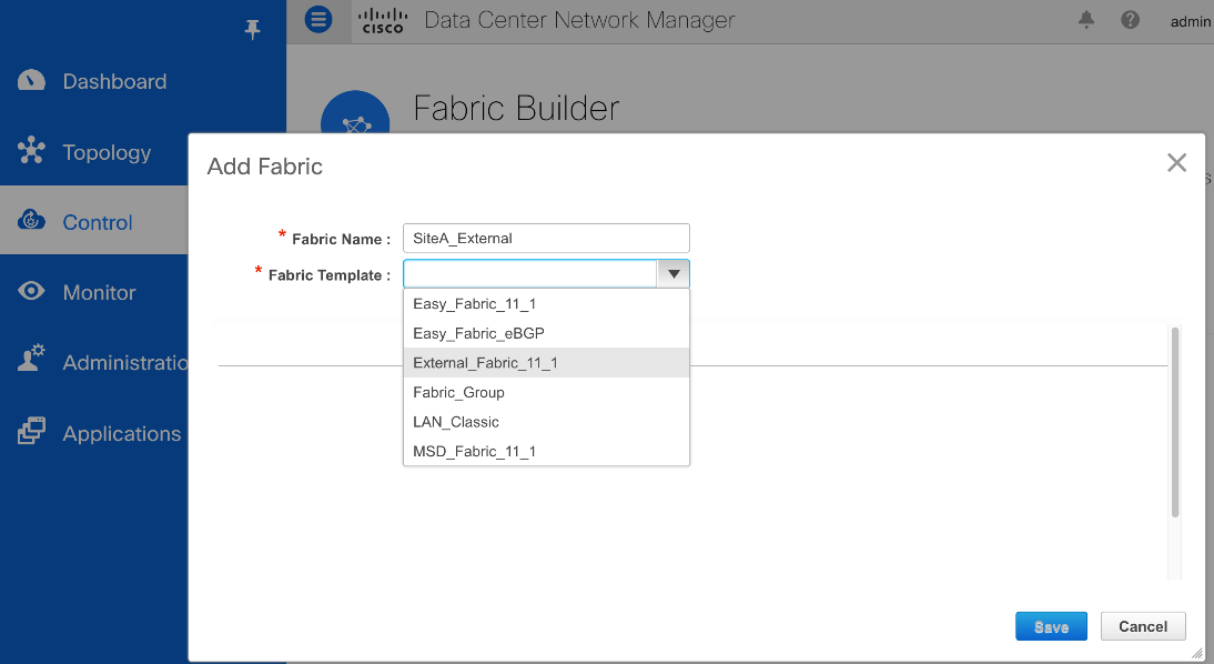
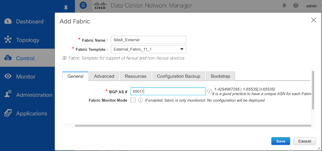
4. The pop-up window will now expand to include multiple tabs for configuring the external fabric. In the General tab, specify the BGP AS# information for the external fabric and deselect Fabric Monitor Mode so that the external fabric can be managed from Cisco DCNM.
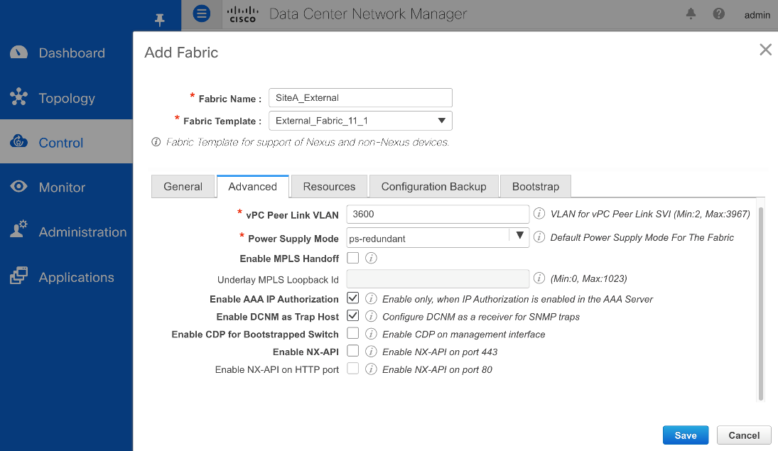
5. In the Advanced tab, select Enable AAA IP Authorization checkbox and leave everything else as-is.
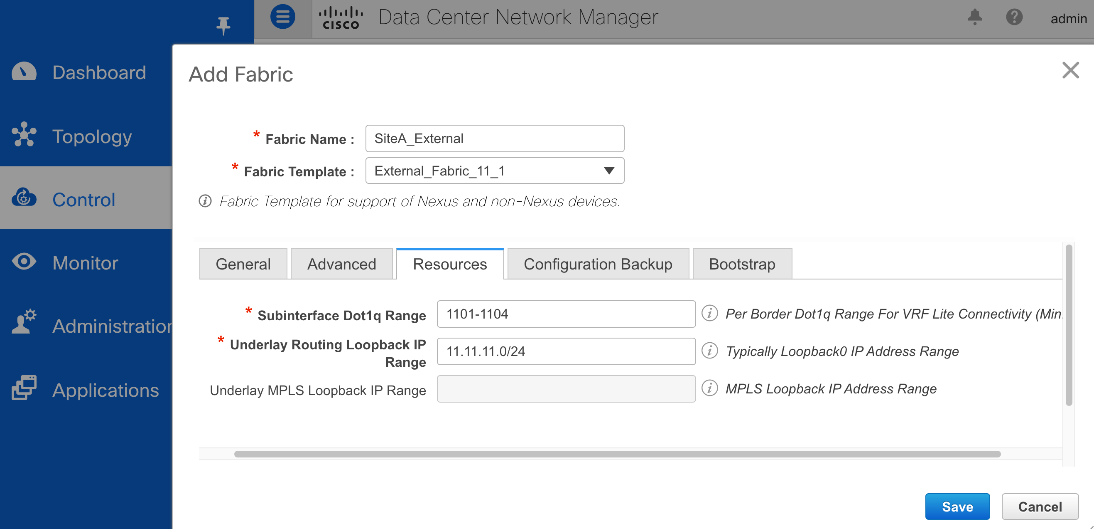
6. (Optional) In the Resources tab, specify the Subinterface Dot1q Range and Underlay Routing Loopback IP
Range.
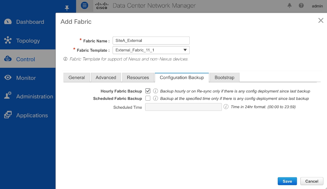
7. (Optional) In the Configuration Backup tab, specify a backup schedule for the fabric as shown below.
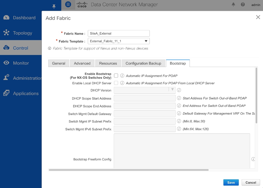
8. (Optional) In the Bootstrap tab, customers can specify bootstrap information if POAP is used to discover and import the switches into the fabric. This was not used in this CVD.
9. Click Save to save the fabric settings for the External Fabric in Site-A. You will get a pop-up on the right-bottom corner saying the Fabric was deployed successfully if the settings were saved. The saved settings are merely the configuration intent at this stage – they will need to be deployed on the switches for it to take effect.
10. At this point, you can start adding switches to the External fabric. Note that you can also use ![]() Fabric Settings in the Actions menu at any time to modify the parameters – however, once switches have been added to the fabric, you will need to do a Save & Deploy (top-right corner) in order to save the settings and then to apply them to the switches in the fabric.
Fabric Settings in the Actions menu at any time to modify the parameters – however, once switches have been added to the fabric, you will need to do a Save & Deploy (top-right corner) in order to save the settings and then to apply them to the switches in the fabric.
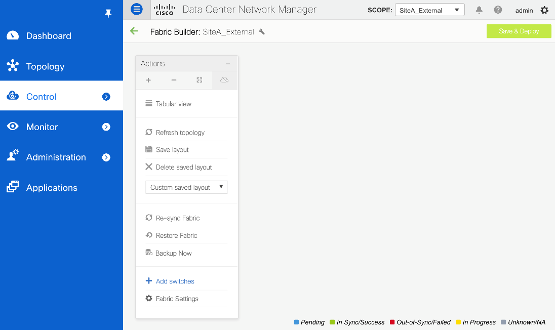
11. Proceed to the next section to discover and add switches to the external fabric to connect to the Site-A data center fabric.
Add Gateway Switches to the External Fabric
As stated earlier, this design assumes a greenfield deployment where the fabric is built from the ground-up. Therefore, this section walks through the discovery, addition, and initial configuration of gateway switches to the external fabric to connect to Site-A data center fabric.
To add gateway switches to the external fabric, follow these steps:
1. In the right-window pane, verify that the SCOPE: is SiteA_External in the drop-down list near the top-right corner. From the Actions menu, select and click Add Switches.
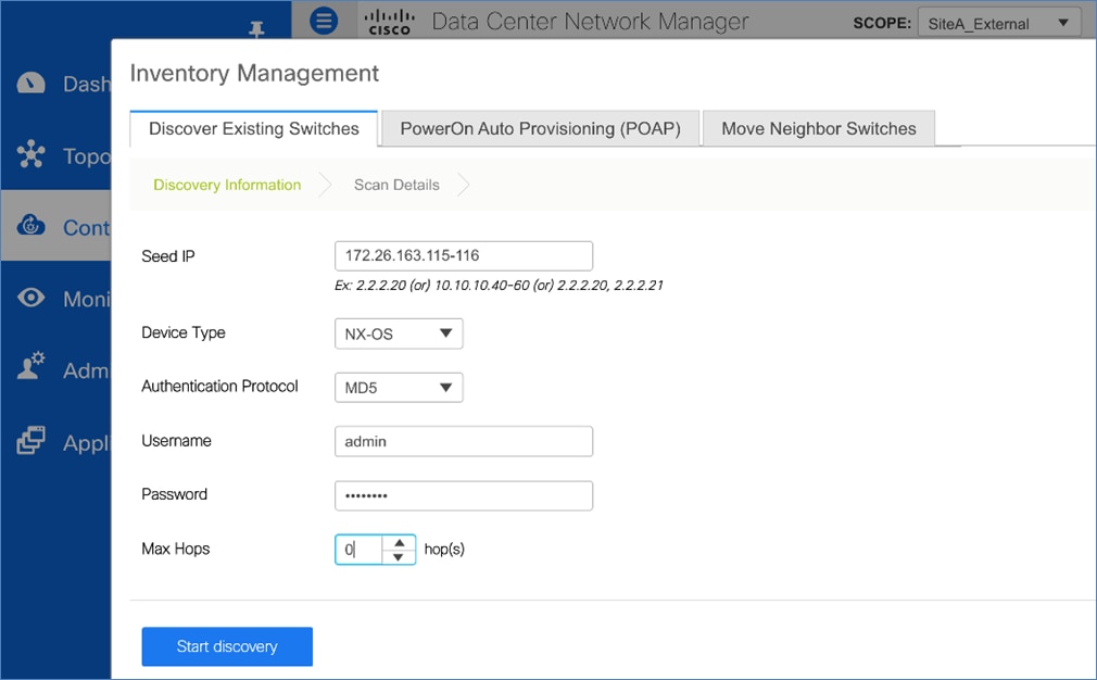
2. In the Inventory Management pop-up window, select the Discover Existing Switches tab. Note that you can also POAP on Cisco DCNM to discover and add switches to the VXLAN fabric. For the Seed IP, specify the IP address range of the switches that need to be discovered. For the Username and Password, specify the administrator username and password for the switches that you can use to log-on to the switches. For the Max Hops, specify ‘0’ to minimize the discovery time.
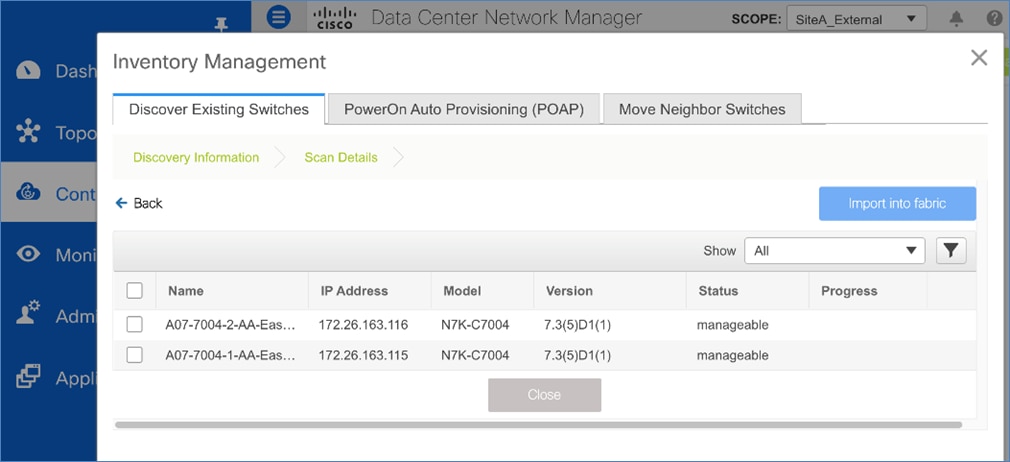
3. Click Start discovery to start the discovery process. You should see a spinning wheel in the red Abort Request button at the bottom as Cisco DCNM attempts to discover and find these switches. Once the discovery completes, you will be provided with a list of switches that can be imported into the fabric.
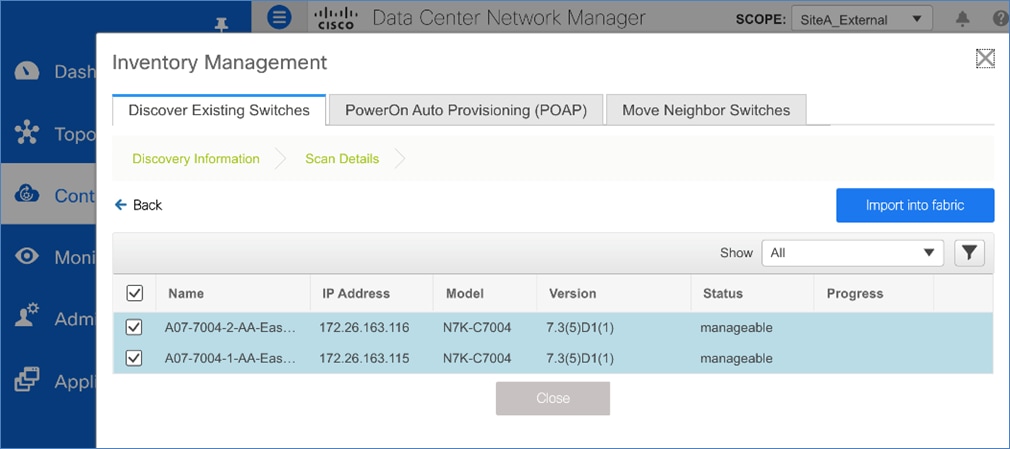
4. Use checkboxes to the left of the switches to select the switches that should be imported into this fabric. In this case, all switches in the list are selected. Click Import into fabric.
5. You can see the progress of the import in the Progress column for each switch being imported.
6. Once imported is complete, the Progress column will show done. Click Close.
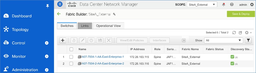
7. For each switch, verify that the Discovery Status is ok. Also, verify the Role of each switch and modify as needed. To change the role, go back to the topology view by clicking on the green left arrow in the top left corner of the right window pane.
8. From the Topology view, change the role of the external gateway switches to Edge Router role. Select the first switch from the topology and right-click. From the menu, select Set role and then Edge Router from the roles list. A small window will pop-up on the bottom right to confirm that the role change was successful.
![]() Cisco recommends the Edge Router role to set up a VRF-lite Inter-Fabric Connection (IFC) from a Border device to an Edge device, which is what this design uses.
Cisco recommends the Edge Router role to set up a VRF-lite Inter-Fabric Connection (IFC) from a Border device to an Edge device, which is what this design uses.
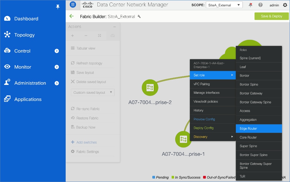
9. Repeat step 18 for the second switch.
10. Verify the roles have changed. From the Actions menu/window, click Tabular view. For each switch, verify that the Role change is correct. You are now ready to save and apply the configuration changes to the switches. Click the Save & Deploy button to apply the changes to both switches in the list.
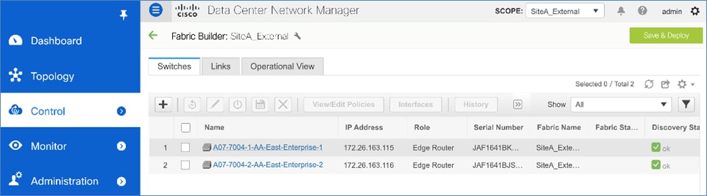
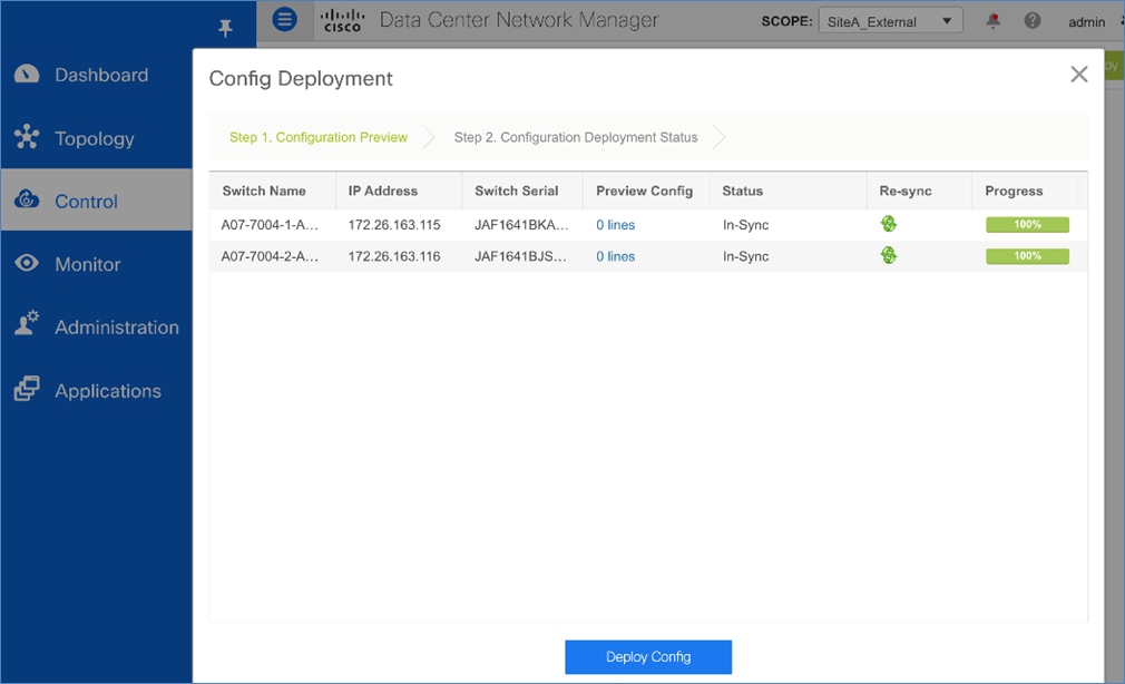
11. In the Config Deployment pop-up window, you can typically see the number of lines of configuration that will be deployed on each switch. The configuration deployed will vary depending on the role of the switch. In this case, zero lines of configuration is deployed. However, the configuration will occur once the inter-fabric links are deployed between External Fabric and Site-A in a later step. Click the Deploy Config button.
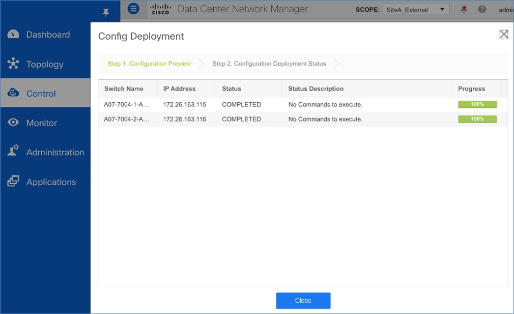
12. In the Config Deployment window, the deployment should complete and go to a COMPLETED status. Click Close.
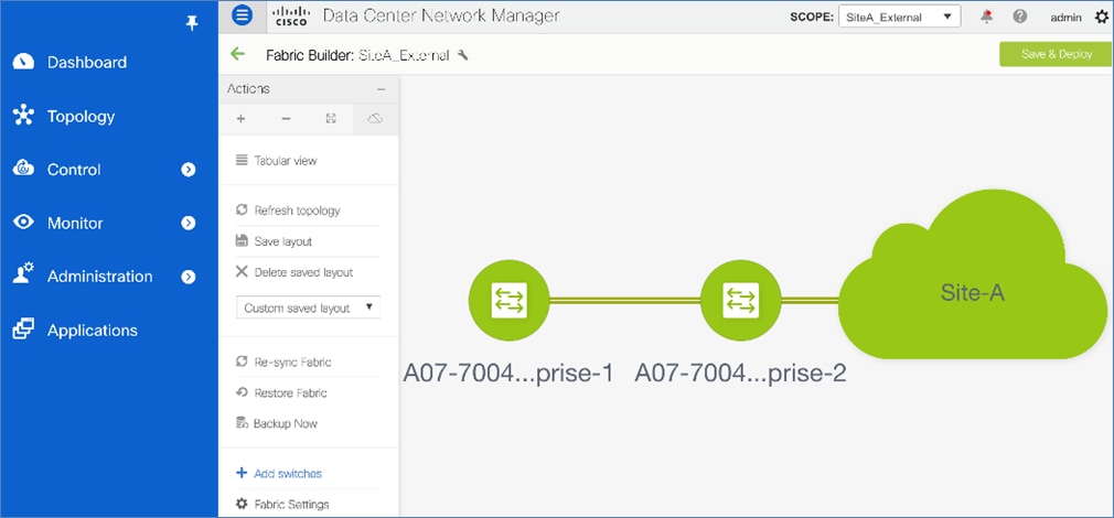
13. Go to Topology view. From the Actions menu/window, select Hierarchical from the drop-down list. The topology view should now change based on the role of the devices. Select Save layout from the Actions menu.
14. The next step is to deploy the Inter-Fabric Connections (IFC) between the external fabric and Site-A.
Deploy Inter-Fabric Connections between External Fabric and Site-A
In this design, the Inter-Fabric Connections (IFCs) are auto-deployed and configured. From the external fabric, you can view and delete IFCs, but you cannot create/edit/deploy them – you must do this from Site-A. To verify that IFCs are discovered and deployed between the External fabric and Site-A data center fabric, follow these steps:
1. From the left navigation menu, select Control > Fabric Builder. Select and click Site-A fabric from the two fabrics listed.
2. From the Site-A topology view, in the Actions menu/window, select Hierarchical from the drop-down list. The topology view should now change based on the role of the devices. Select Save layout from the Actions menu.
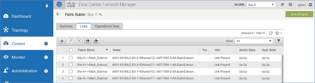
3. From the Actions menu/window, select Tabular view. Select the Links tab. Click Fabric Name to sort and find the 4 IFC links used in this design – they are automatically deployed by Cisco DCNM. The Fabric Name will have both fabrics in the name as shown below. Verify that each IFC link has a status of Link Present, Admin State of Up:Up and Oper State of Up:Up.
4. Select one of the IFC links by selecting the checkbox to the left of the link.
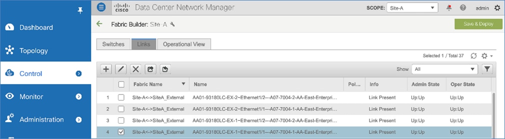
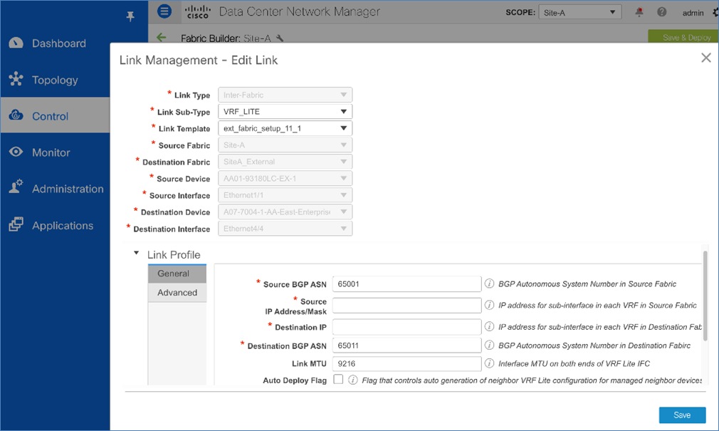
5. Click the ![]() to edit the IFC link. In the Link Management – Edit Link pop-up window, under the Link Profile > General section, note that the Source IP Address/Mask and Destination IP are not configured. Also, the Auto Deploy Flag is disabled. All other fields are populated as shown below. Click X to close this window.
to edit the IFC link. In the Link Management – Edit Link pop-up window, under the Link Profile > General section, note that the Source IP Address/Mask and Destination IP are not configured. Also, the Auto Deploy Flag is disabled. All other fields are populated as shown below. Click X to close this window.
6. From the Links tab view, click the Save & Deploy button.
7. From the Config Deployment pop-up window, click the Deploy Config button.
8. When the deployment completes and the status is COMPLETED, click the Close button to close this window.
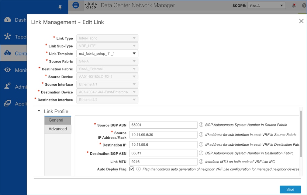
9. From the Links tab view, select the same IFC link as in step 5 above and click the ![]() to edit the IFC link. In the Link Management – Edit Link pop-up window, under the Link Profile > General section, note that the Source IP Address/Mask and Destination IP are now configured. Also, the Auto Deploy Flag is now enabled. The Save & Deploy from Step 6 applied the Fabric Settings for VRF-Lite and auto-deployed the necessary configuration. Click X to close the window.
to edit the IFC link. In the Link Management – Edit Link pop-up window, under the Link Profile > General section, note that the Source IP Address/Mask and Destination IP are now configured. Also, the Auto Deploy Flag is now enabled. The Save & Deploy from Step 6 applied the Fabric Settings for VRF-Lite and auto-deployed the necessary configuration. Click X to close the window.
10. You can verify the remaining three IFC links - they should all be configured also after the Save & Deploy.
11. For each IFC link, in the Link Profile > Advanced section, configure the Source Interface Description and the Destination Interface Description as shown below.
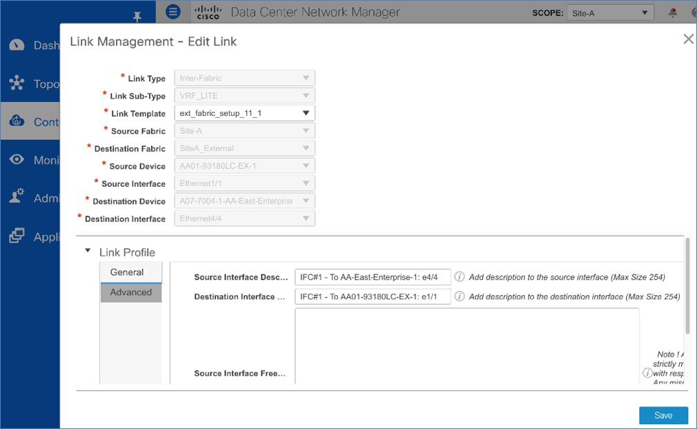
12. Click Save to save the settings for the first IFC link.
13. Repeat steps 11 and 12 for the remaining 3 IFC links.
14. Go to Switch tab. The Border Leaf switches should be in Pending state. Click on the Save & Deploy button.
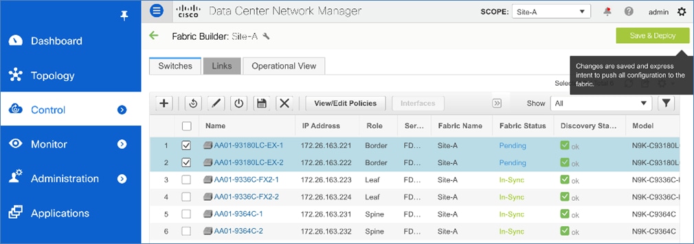
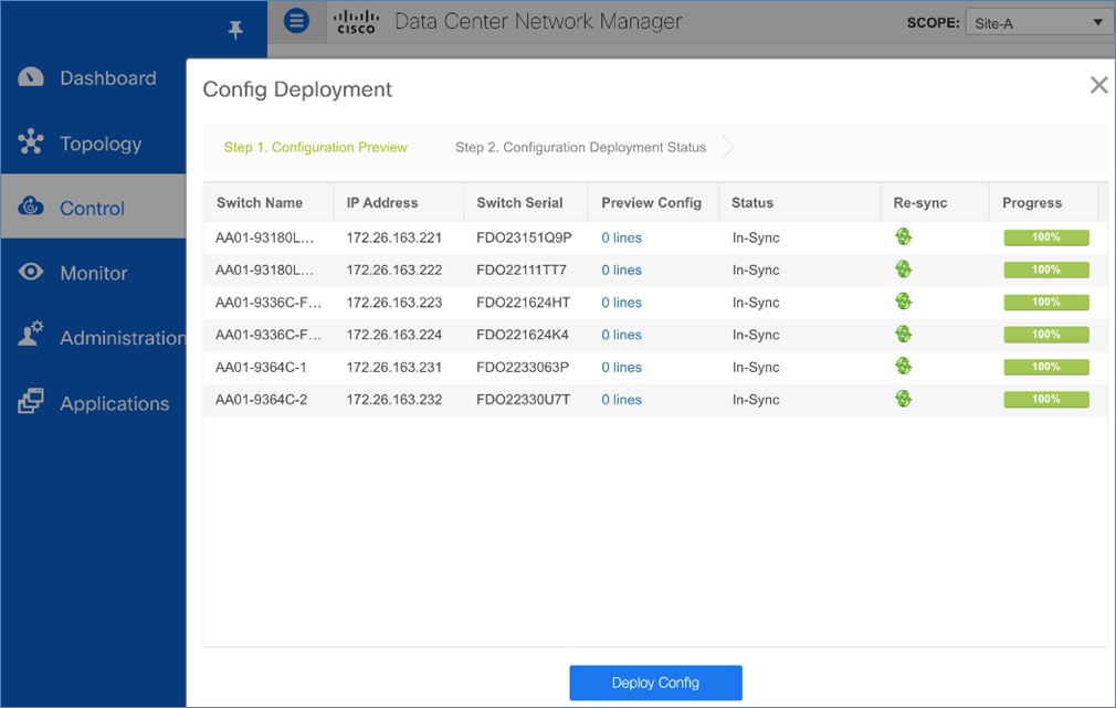
15. In the Config Deployment pop-up window, the Border switches should be Out-of-Sync, with about 11 lines of configuration change. Click on the ‘11 lines’ to view the exact changes that will be deployed. Click the Deploy Config button.
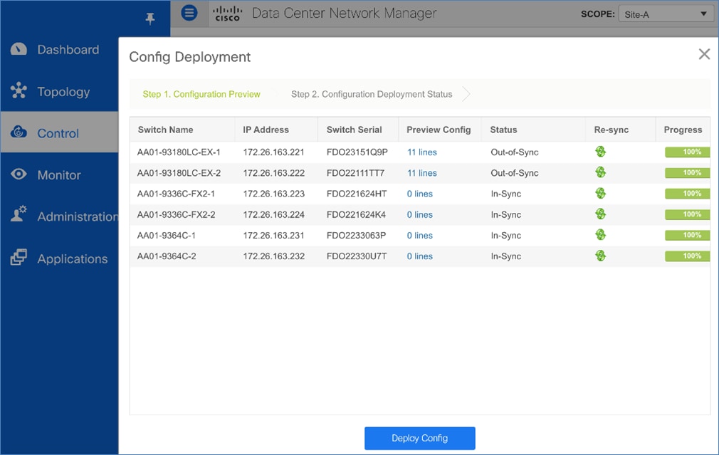
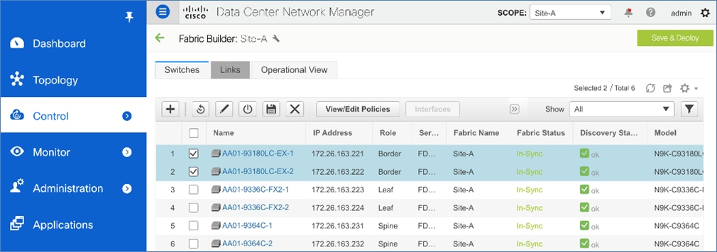
16. When the deployment completes, click the Close button to close the window. The switches should now be in an In-Sync state.
17. From the top-right corner of the window, for Scope: , select SiteA_External from the drop-down list.
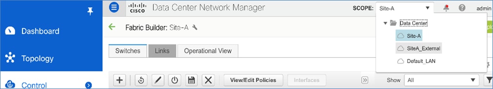
18. Note that the external gateways are in a Pending state. Click the Save & Deploy button.
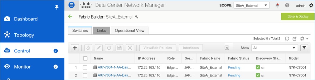
19. In the Config Deployment pop-up window, the External Gateway switches should be Out-of-Sync, with about 11 lines of configuration change. Click on the ‘11 lines’ to view the exact changes that will be deployed. Click the Deploy Config button.
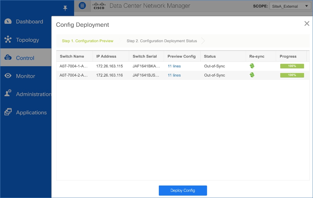
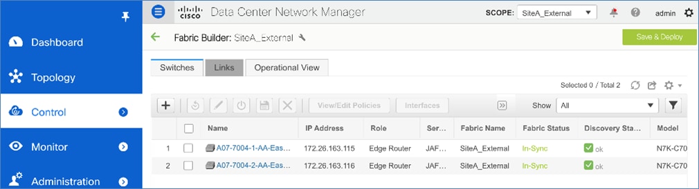
20. When the deployment completes, click the Close button to close the window. The switches should now be in an In-Sync state.
You are now ready to deploy the infrastructure networks that FlexPod requires.
Enable Access Layer Connectivity to Cisco UCS Domain
In this section, access-layer connectivity is enabled from the VXLAN fabric in Site-A to the Cisco UCS infrastructure used in the FlexPod solution. The Cisco UCS infrastructure consists of a pair of Cisco UCS Fabric Interconnects that connects to Cisco UCS B-series and C-series servers.
Topology
Setup Information
The configuration parameters for enabling access-layer connectivity to Cisco UCS Domain in Site-A data center fabric is provided below.
Table 8. Access Layer Switches – To Cisco UCS Domain
| Hostname |
Switch Role |
IP Address (OOB) |
Notes |
| AA01-9336C-FX2-1 |
Leaf |
172.26.163.223/24 |
|
| AA01-9336C-FX2-2 |
Leaf |
172.26.163.224/24 |
|
Table 9. Access Layer Connectivity – To Cisco UCS Domain
| Access Layer Connection |
Parameters |
Notes |
| Type |
Virtual Port-Channel (vPC) |
Using Virtual Peer-Links (requires hardware support) |
| vPC Pair |
AA01-9336C-FX2-1---AA01-9336C-FX2-2 |
|
| vPC to Cisco UCS FI-A |
||
| Peer-1 Member Interfaces |
Ethernet 1/1 |
|
| Peer-2 Member Interfaces |
Ethernet 1/1 |
|
| Peer-1 PO Description |
To FXV-AA01-UCS6454FI-A: e1/53 |
|
| Peer-2 PO Description |
To FXV-AA01-UCS6454FI-A: e1/54 |
|
| vPC to Cisco UCS FI-B |
||
| Peer-1 Member Interfaces |
Ethernet 1/2 |
|
| Peer-2 Member Interfaces |
Ethernet 1/2 |
|
| Peer-1 PO Description |
To FXV-AA01-UCS6454FI-B: e1/53 |
|
| Peer-2 PO Description |
To FXV-AA01-UCS6454FI-B: e1/54 |
|
Deployment Steps
To enable access-layer connectivity from Site-A data center fabric to the Cisco UCS domain, follow these steps using the Setup Information provided above:
1. Use a browser to navigate to Cisco DCNM’s GUI. Log in using an administrator account.
2. From the left navigation bar, select Control > Fabrics > Fabric Builder. Click on the Site-A fabric.
3. From the right window pane, select one of the Leaf switches that connect to the Cisco UCS domain.
4. Right-click and select vPC Pairing from the list.
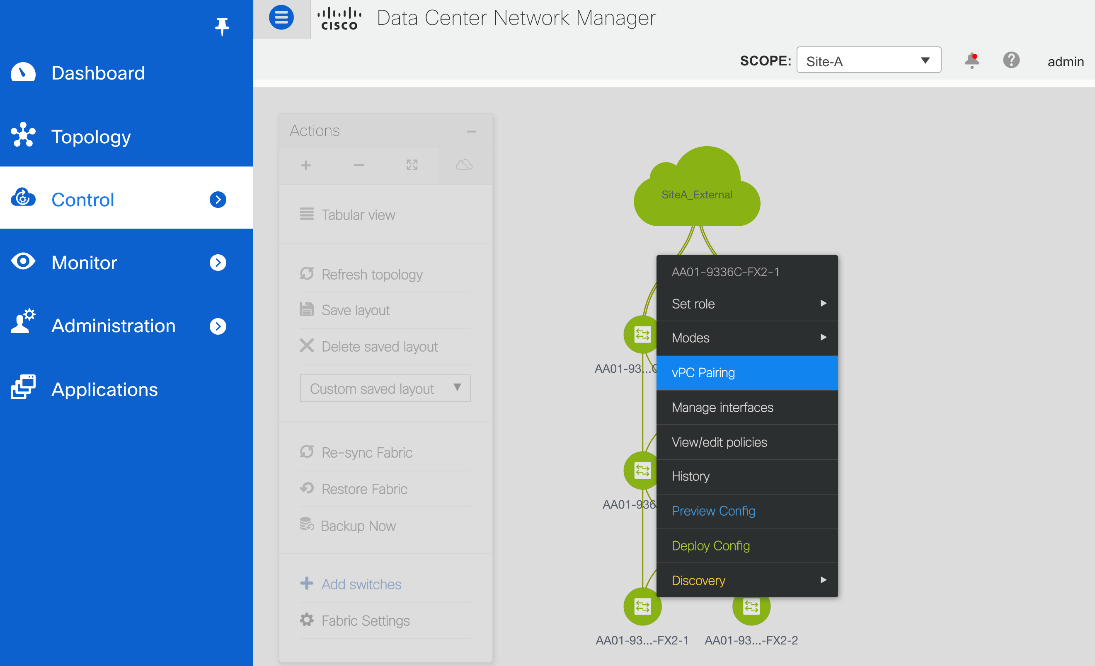
5. In the vPC peer for Leaf switch pop-up window, enable the checkbox next to Use Virtual Peer link and select the radio button for peer Leaf switch that will be part of the vPC pair for the vPC going to the Cisco UCS Fabric Interconnects in the UCS domain.
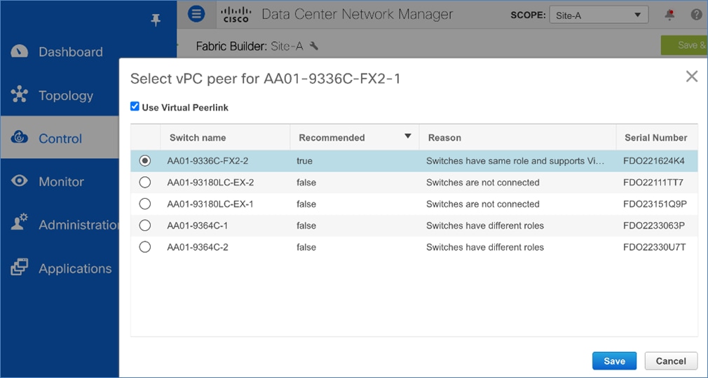
6. Click Save. A small pop-up window will show up on the right-bottom corner of the window to indicate whether the vPC pairing is successful. Note that the two leaf switches in the vPC pair are now grouped together in the topology view. Click the Save & Deploy button to deploy the vPC pairing.
7. In the Config Deployment pop-up window, note that the leaf switches are Out-of-Sync, with 56 lines of configuration to be deployed.
8. Click on the 56 lines for one of the switches to preview the pending configuration on that switch.
9. Click the X to close the preview window. Click on Deploy Config button to deploy the configuration.
10. When the deployment completes successfully with a COMPLETED status, click on the Close button to close the window. Now you can start configuring access layer connectivity to Cisco UCS domain.
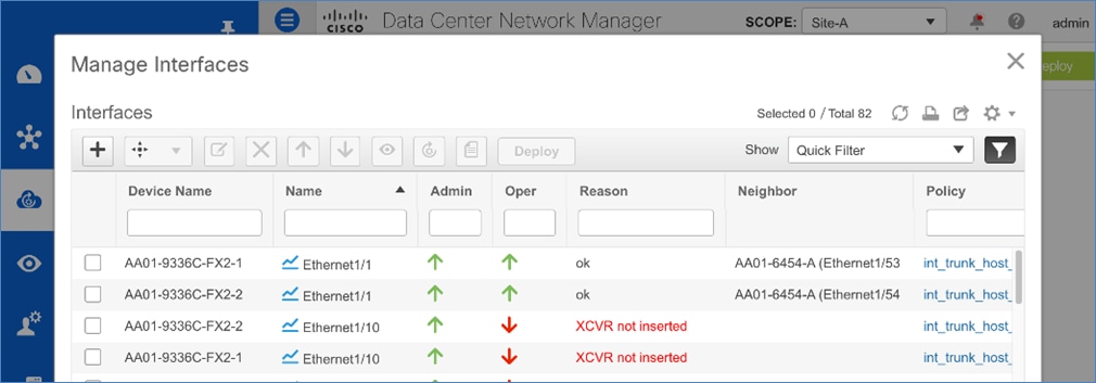
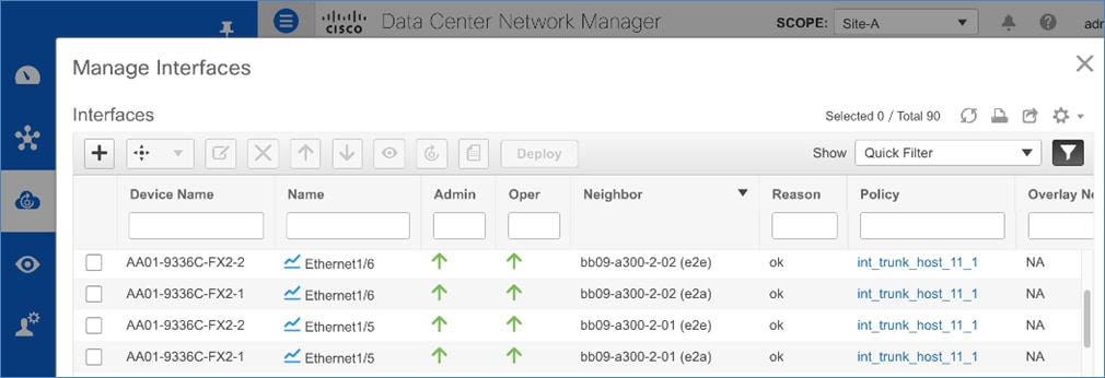
11. Select one of the Leaf switches that connect to the Cisco UCS domain. Right-click and select Manage Interfaces from the list. In the Manage Interfaces pop-up window, bring the Neighbors column into view by dragging it from the far-right end and move it next to the Reason column. Note the interfaces on the leaf switches in the vPC pair that connect to the first UCS FI and the port numbers they connect to.
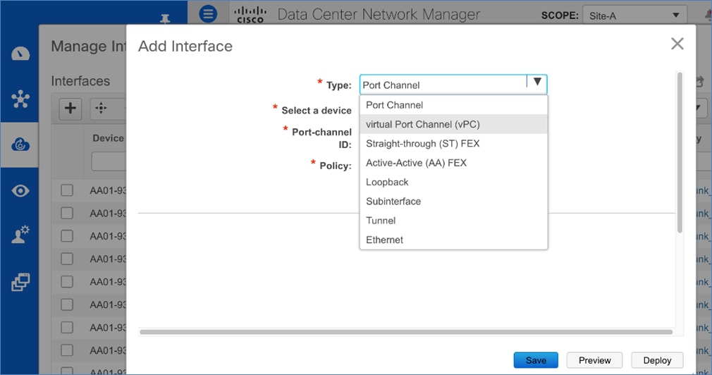
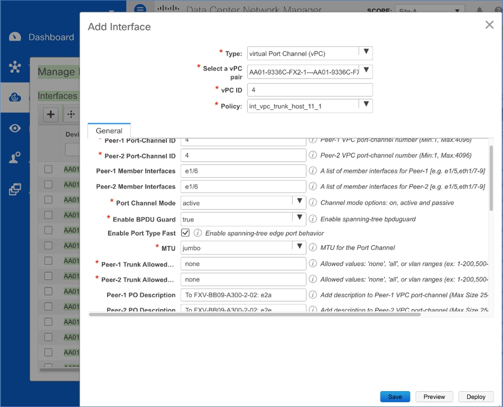
12. Click the [+] button from the menu above. In the Add Interface pop-up window, specify the Type from the drop-down list.

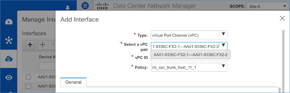
13. The menu changes to the reflect the options for the Interface Type selected. Select a vPC pair from the drop-down list.
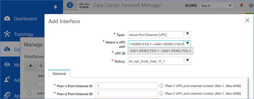
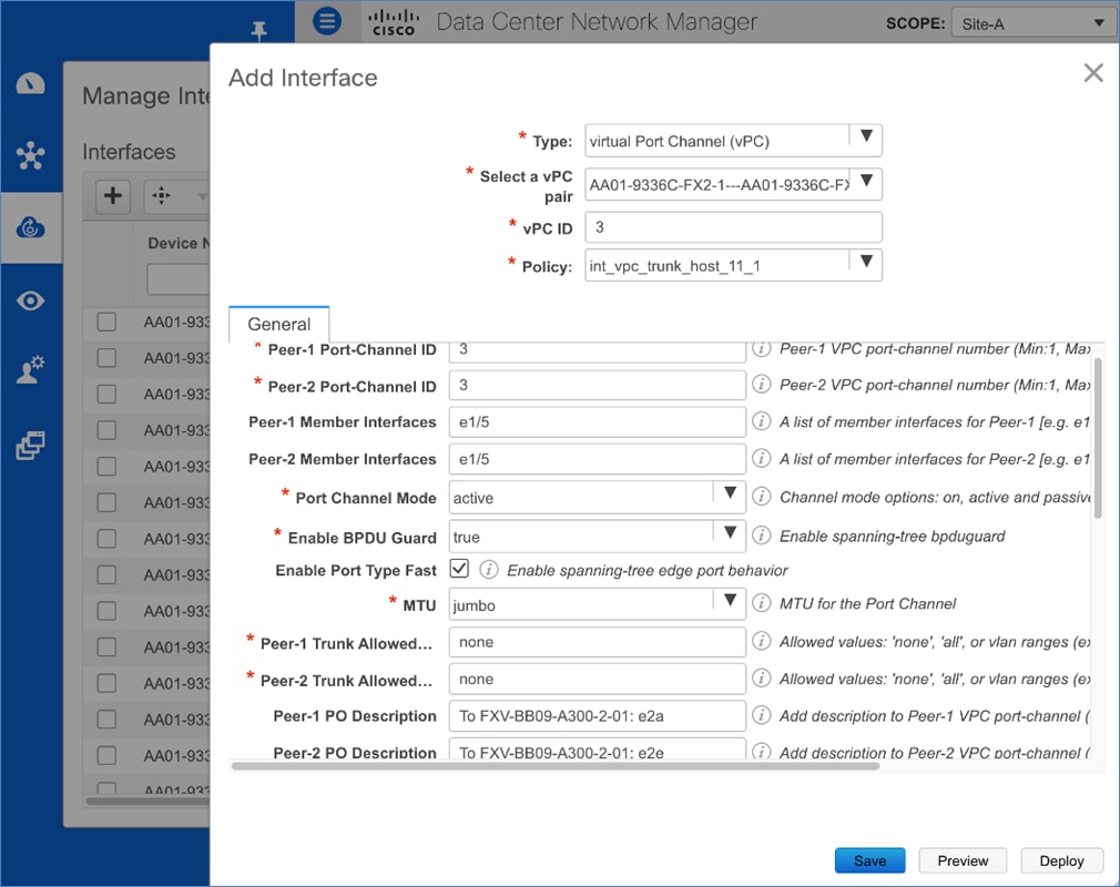
14. Specify the Peer-1 Member Interfaces, Peer-2 Member Interfaces, Peer-1 PO Description, and Peer-2 PO Description. Leave all other fields as-is.
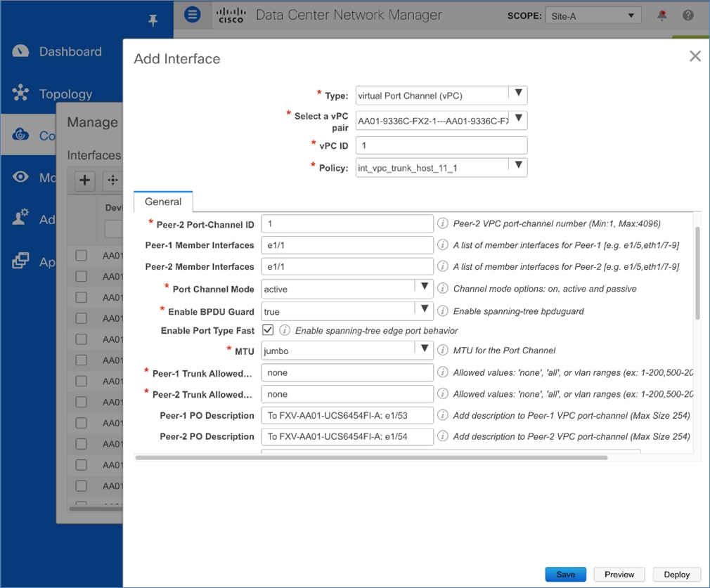
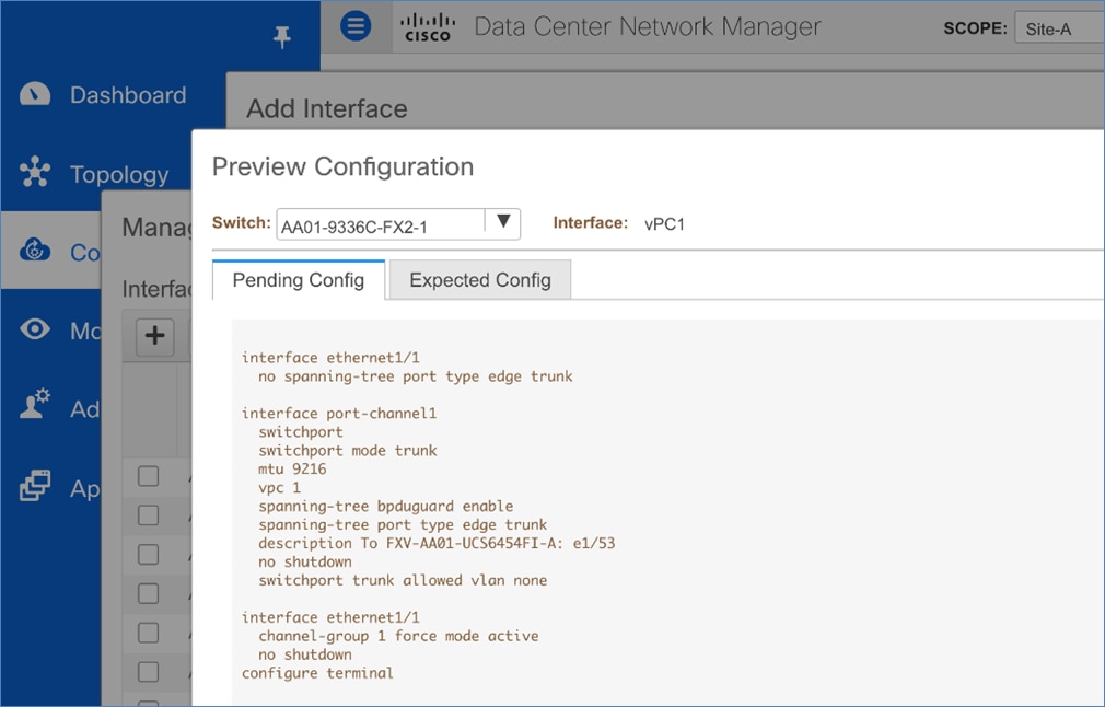
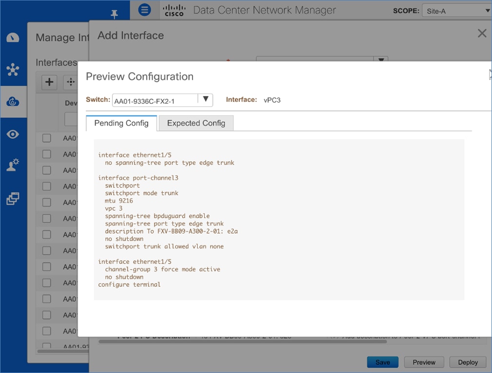
15. Click Save. You can also Preview configuration for the vPC to Cisco UCS FI-A using the Preview button. The preview will display the pending configuration for each switch in the vPC pair – use the drop-down list to select the second switch.
16. Click Deploy to deploy the vPC configuration from the Leaf switch pair in the VXLAN fabric to the first Cisco UCS Fabric Interconnect (FI-A). Click OK in the pop-up window.
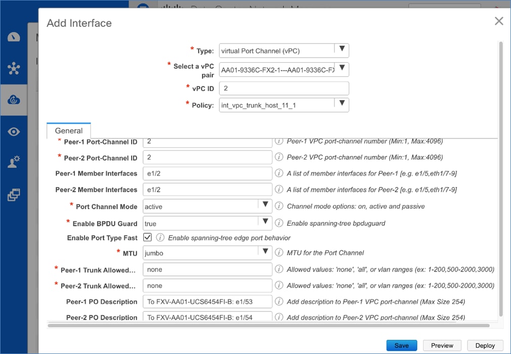
17. Repeat steps 1-16 to create, preview, and deploy the vPC to Cisco UCS FI-B.
18. Click Save. Click on Preview and Deploy to preview and deploy the configuration for the vPC from the leaf switches in the VXLAN fabric to the second Cisco UCS Fabric Interconnect (FI-B). Click OK in the pop-up window. Click the X to close the Manage Interfaces window.
19. From the left navigation bar, select Control > Fabric > Fabric Builder. Select Site-A fabric. In the Topology view, address any issues that are highlighted next to the Save & Deploy button.
20. There are 2 issues in this deployment. Click on the issues to get more information.
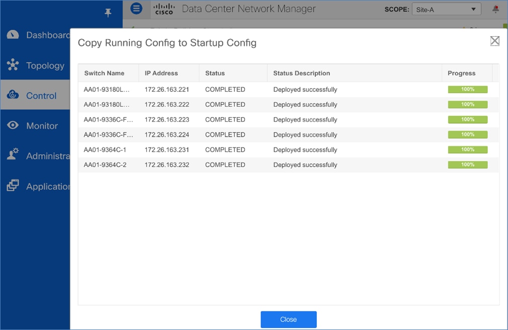
21. To address the warnings, from the Action menu/window, click on Tabular view. Select all switches and click on the floppy drive icon to save the configuration on all switches.

22. Click Close when the save completes successfully.

23. Deselect all the switches and select only the switches that need to be reloaded per the Warning. Click on the Power icon to reboot the switches. Click OK in the pop-up window. Monitor the Discovery Status column for a status as the switch reboots or access the console of the switch in question directly.
24. When the reboot completes after a few minutes, verify that the vPC is in a consistent state and the port-channel is up and operational.
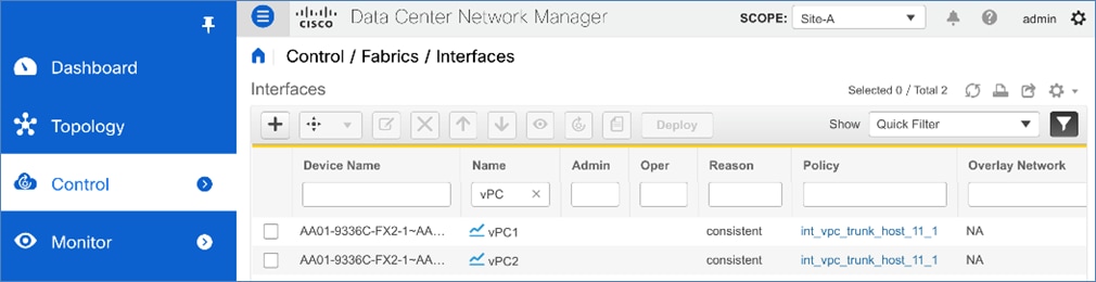
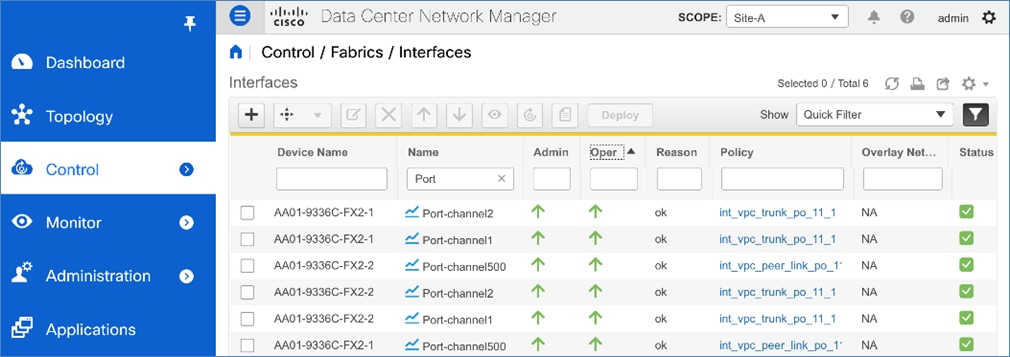
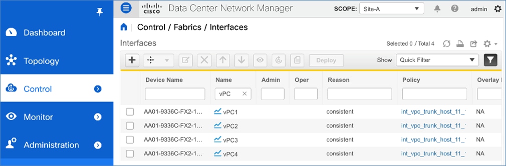
25. From the left navigation bar, select Control > Fabric > Interfaces. Filter on the Name to view the vPCs deployed. Select the Quick Filter from the drop-down list next to Show to see the boxes for filtering under each column. Confirm that the vPC are in a Consistent state – see Reason column.
26. Filter on the Name to view the Port-Channels in the above vPCs. Note that the Admin and Oper status are up. Scroll to the right to see additional columns. Verify that the status is Green.
27. From the left navigation bar, select Control > Fabric > Fabric Builder. Select Site-A fabric. From the Actions menu/window, select Backup Now to back up the Site-A fabric. Repeat the same for the SiteA_External fabric by changing the Scope: to SiteA_External from the drop-down list.
Enable Access Layer Connectivity to NetApp Storage Cluster
In this section, access-layer connectivity is enabled from the VXLAN fabric in Site-A to the NetApp Storage infrastructure in the solution. The NetApp storage infrastructure in this solution consists of an AFF A300 storage array.
Topology
Setup Information
The configuration parameters for enabling access-layer connectivity to NetApp storage cluster in Site-A data center fabric is provided below.
Table 10. Access Layer Switches – To NetApp Storage Cluster
| Hostname |
Switch Role |
IP Address (OOB) |
Notes |
| AA01-9336C-FX2-1 |
Leaf |
172.26.163.223/24 |
|
| AA01-9336C-FX2-2 |
Leaf |
172.26.163.224/24 |
|
Table 11. Access Layer Connectivity – To NetApp Storage Cluster
| Access Layer Connection |
Parameters |
Notes |
| Type |
Virtual Port-Channel (vPC) |
Using Virtual Peer-Links (requires hardware support) |
| vPC Pair |
AA01-9336C-FX2-1---AA01-9336C-FX2-2 |
|
| vPC to NetApp Controller-A |
||
| Peer-1 Member Interfaces |
Ethernet 1/5 |
|
| Peer-2 Member Interfaces |
Ethernet 1/5 |
|
| Peer-1 PO Description |
To FXV-BB09-A300-2-01: e2a |
|
| Peer-2 PO Description |
To FXV-BB09-A300-2-01: e2e |
|
| vPC to NetApp Controller-B |
||
| Peer-1 Member Interfaces |
Ethernet 1/6 |
|
| Peer-2 Member Interfaces |
Ethernet 1/6 |
|
| Peer-1 PO Description |
To FXV-BB09-A300-2-02: e2a |
|
| Peer-2 PO Description |
To FXV-BB09-A300-2-02: e2e |
|
Deployment Steps
To enable access-layer connectivity from Site-A data center fabric to the NetApp Storage Cluster, follow these steps using the Setup Information provided above:
1. Use a browser to navigate to Cisco DCNM’s GUI. Log in using an administrator account.
2. From the left navigation bar, select Control > Fabrics > Fabric Builder. Click on the Site-A fabric.
3. From the right window pane, select one of the Leaf switches in the vPC pair that connect to the NetApp Storage Cluster. Right-click and select Manage Interfaces from the list.
4. In the Manage Interface pop-up window, bring the Neighbors column into view by dragging it from the far-right end and move it next to the Reason column. Sort the interfaces based on the Neighbor column. Note the interfaces on the leaf switches in the vPC pair that connect to the first NetApp controller and the port numbers they connect to.
5. Click the [+] button from the menu above. In the Add Interface pop-up window, specify the Type from the drop-down list.
6. The menu changes to the reflect the options for the Interface Type selected. Select a vPC pair from the drop-down list.
7. Specify the Peer-1 Member Interfaces, Peer-2 Member Interfaces, Peer-1 PO Description, and Peer-2 PO Description. Leave all other fields as-is.
8. Click Save. You can also Preview configuration for the vPC to the first NetApp controller using the Preview button. The preview will display the pending configuration for each switch in the vPC pair – use the drop-down list to select the second switch.
9. Click X to close the window. Click Deploy to deploy the vPC configuration from the Leaf switch pair in the VXLAN fabric to the first NetApp controller. Click OK in the pop-up window.
10. Repeat steps 1-9 to create, preview, and deploy the vPC to the second NetApp controller.
11. Click Save. Click on Preview and Deploy to preview and deploy the configuration for the vPC from the leaf switches in the VXLAN fabric to the second Cisco UCS Fabric Interconnect (FI-B). Click OK in the pop-up window. Click X to close the Manage Interfaces window.
12. From the left navigation bar, select Control > Fabric > Fabric Builder. Select Site-A fabric. In the Topology view, see if any issues that are highlighted next to the Save & Deploy button.
13. From the Actions menu/window, click on Tabular view. Select all switches and click on the floppy drive icon to save the configuration on all switches.
14. Click Close when the save completes successfully.
15. Verify that the vPC is in a consistent state and the port-channel is up and operational.
16. From the left navigation bar, select Control > Fabric > Interfaces. Filter on the Name to view the vPCs deployed. Select the Quick Filter from the drop-down list next to Show to see the boxes for filtering under each column. Confirm that the vPC are in a Consistent state – see Reason column.
17. Filter on the Name to view the Port-Channels in the above vPCs. Note that the Admin and Oper status are up. Scroll to the right to see additional columns. Verify that the status is Green.
18. From the left navigation bar, select Control > Fabric > Fabric Builder. Select Site-A fabric. From the Actions menu/window, select Backup Now to back up the Site-A fabric.
Enable Network Connectivity for FlexPod Infrastructure
To enable access to FlexPod infrastructure resources, namely compute and storage, the corresponding infrastructure networks must be first deployed in the VXLAN fabric in order to bring up the compute and storage infrastructure. The FlexPod infrastructure is isolated using a dedicated tenant/VRF (FPV-Foundation_VRF). Connectivity to external networks is also enabled directly from within FPV-Foundation_VRF. This tenant is not used for applications workloads hosted on the FlexPod Virtual Server Infrastructure (VSI) though it is used by management components such as VMware vCenter, NetApp VSC and so on. that is used to manage and operate the FlexPod VSI.
Setup Information
The configuration parameters for deploying the FlexPod infrastructure networks in Site-A data center fabric are provided below.
Table 12. Data Center Information
| Scope |
Site-A |
Table 13. Infrastructure Tenant/VRF
| VRF Name |
VRF VLAN Name |
VRF Interface Description |
VRF Description |
| FPV-Foundation_VRF |
FPV_Foundation_VRF_VLAN |
FPV_Foundation_VRF_Interface |
FPV_Foundation_VRF |
Table 14. Infrastructure Networks - FPV-Foundation_VRF
| Network Name |
VLAN |
VLAN Name |
Forwarding |
IP Subnet /Gateway* |
VXLAN Network ID (VNID) |
Notes |
| FPV-iSCSI-A_Network |
3010 |
FPV-iSCSI-A_VLAN |
Layer 2 Only |
192.168.10.0/24 |
20000 |
ARP Suppression – N/A in L2-only mode |
| FPV-iSCSI-B_Network |
3020 |
FPV-iSCSI-B_VLAN |
Layer 2 Only |
192.168.20.0/24 |
20001 |
“ |
| FPV-InfraNFS_Network |
3050 |
FPV-InfraNFS_VLAN |
Layer 2 Only |
192.168.50.0/24 |
20002 |
“ |
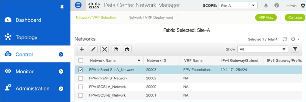
| FPV-InBand-SiteA_Network |
122 |
FPV-InBand-SiteA_VLAN FPV-InBand-SiteA_Interface |
Layer 3 |
10.1.171.254/24* |
20003 |
In-Band Management Network (e.g. ESXi hosts) |
| FPV-vMotion_Network |
3000 |
FPV-vMotion_VLAN |
Layer 2 Only |
192.168.10.0/24 |
20004 |
“ |
| FPV-CommonServices_Network |
322 |
FPV-CommonServices_VLAN |
Layer 3 |
10.3.171.254/24* |
20005 |
Hosts VMware vCenter and NetApp VSC |
* Gateway IP is configured only for L3 Forwarding and the default gateway is in the VXLAN Fabric
Deploy FlexPod Infrastructure Tenant in Cisco DCNM
To create the FlexPod Infrastructure Tenant in Cisco DCNM, use the Setup Information provided above to follow these steps:
1. Use a browser to navigate to Cisco DCNM’s GUI. Log in using an administrator account.
2. From the left navigation bar, select Control > Fabrics > VRFs. Click OK in the pop-window that complains about an Unsupported Fabric Data Center selected. Use Scope: to change the scope to Site-A.
3. Click on the [+] icon to deploy a new Tenant VRF for the FlexPod infrastructure traffic. Specify a VRF VLAN Name, VRF Interface Description and VRF Description. Click the Create VRF button.
4. A small pop-up box will appear in the bottom-right corner to confirm that the VRF was created successfully. Click the Continue button.
5. Click the Detailed View button.

6. Select the checkbox for all Leaf and Border switches in the list. Click the Quick Attach button.
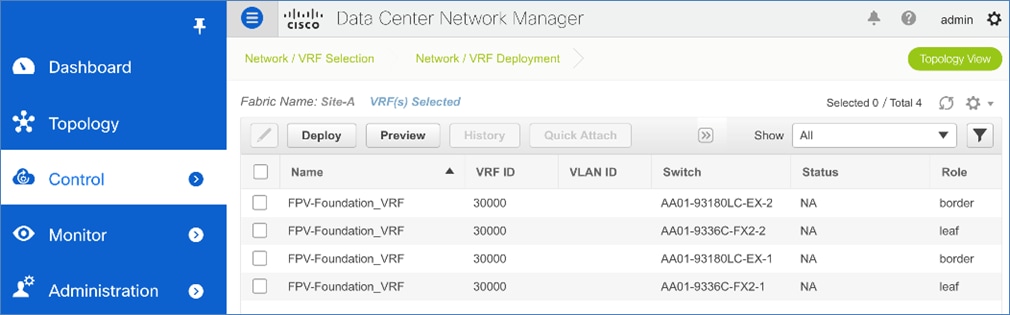
7. Click OK.

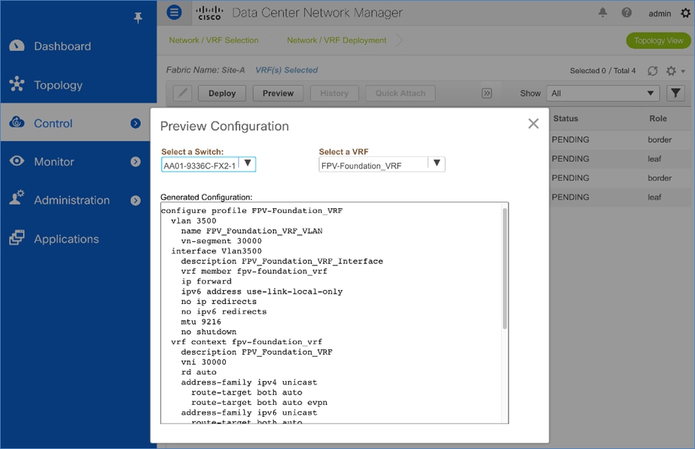
8. Click the Preview button to preview the pending configuration on all the Leaf and Border switches. Click X to close the Preview Configuration window.
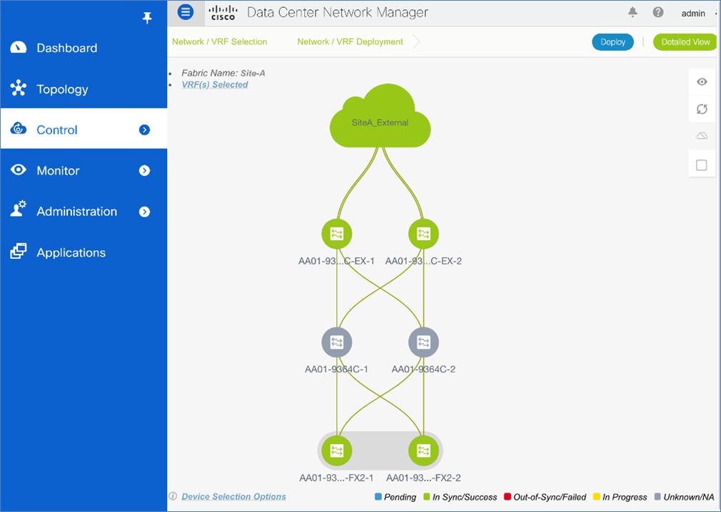
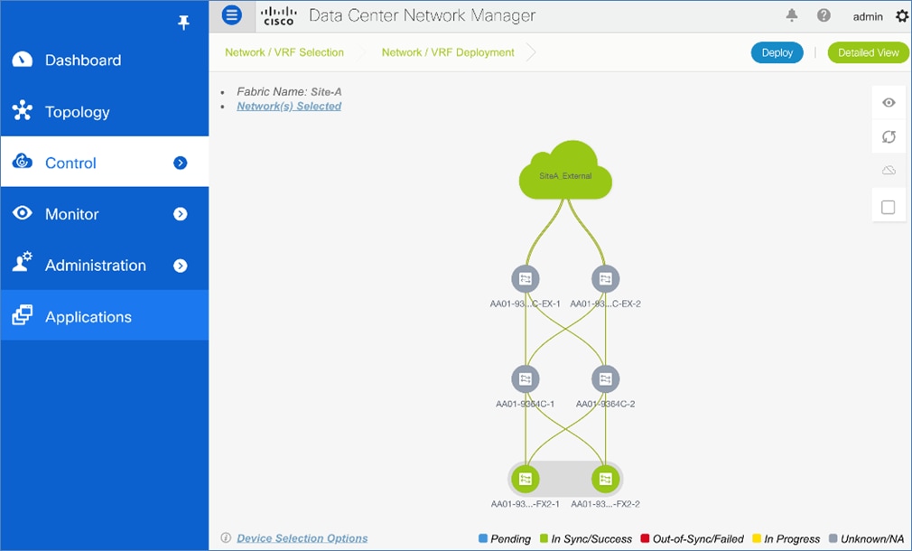
9. Click the Deploy button. Once the configuration is deployed, the Status go from PENDING to IN PROGRESS to DEPLOYED. Click the Topology View button.

10. In the Topology View to see the where the selected VRF is deployed in the Site-A topology.
Deploy FlexPod Infrastructure Networks
To create the FlexPod Infrastructure Tenant networks in Cisco DCNM, use the Setup Information provided above to complete the steps in the upcoming sections.
Deploy FlexPod Storage Networks
The FlexPod storage networks, namely iSCSI-A, iSCSI-B and NFS networks are deployed in this design in Layer 2 Only mode with no gateway defined in the VXLAN fabric. To deploy the FlexPod Storage Networks, follow these steps:
1. Use a browser to navigate to Cisco DCNM’s GUI. Log in using an administrator account.
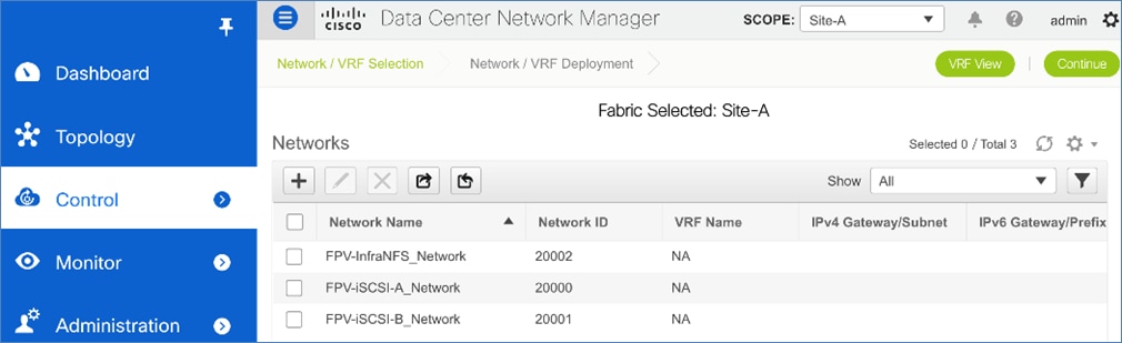
2. From the left navigation bar, select Control > Fabrics > Networks.
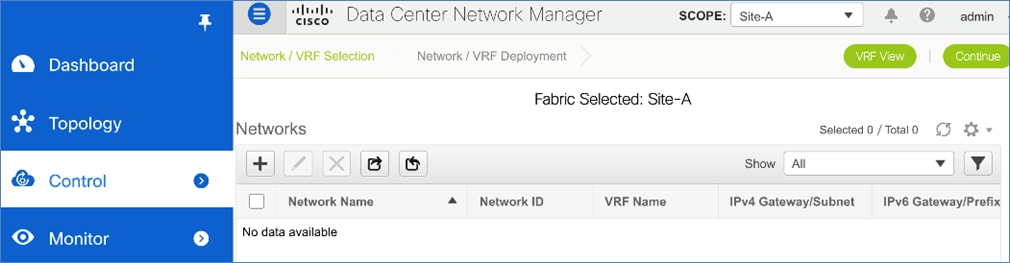
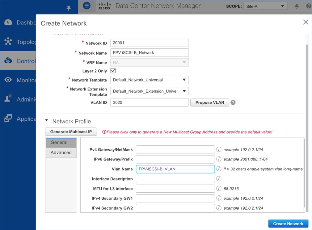
3. Click on the [+] icon to deploy a new Tenant network for the FlexPod infrastructure traffic. Specify a Network Name. Select the checkbox for Layer 2 Only mode. Specify a VLAN ID. In the Network Profile > General section, specify a VLAN name. Leave everything else as-is.
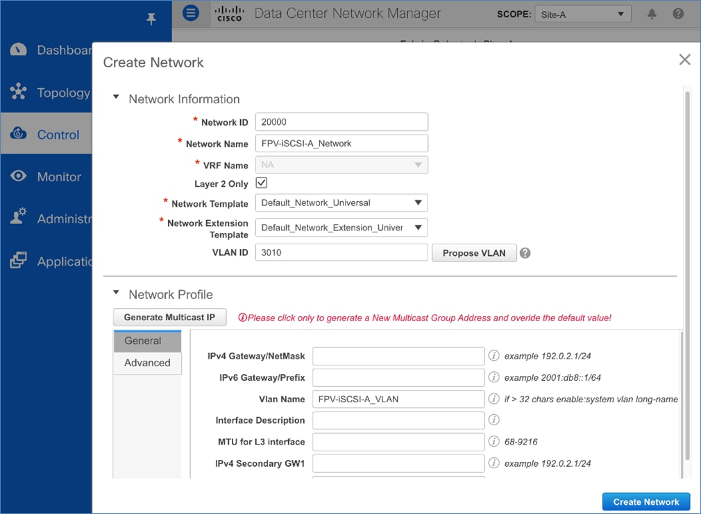
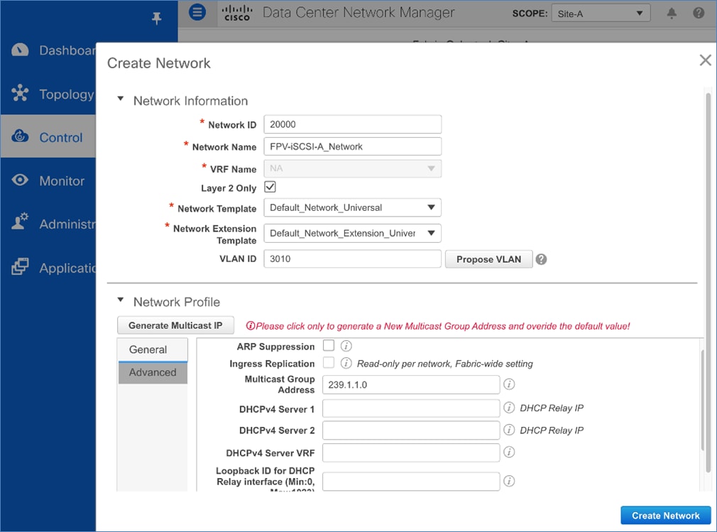
4. In the Network Profile > Advanced section, leave everything as-is.
5. Click the Create Network button.
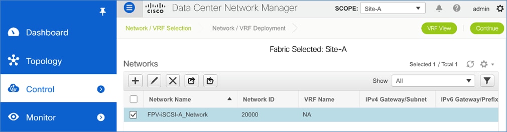
6. Click the Continue button.
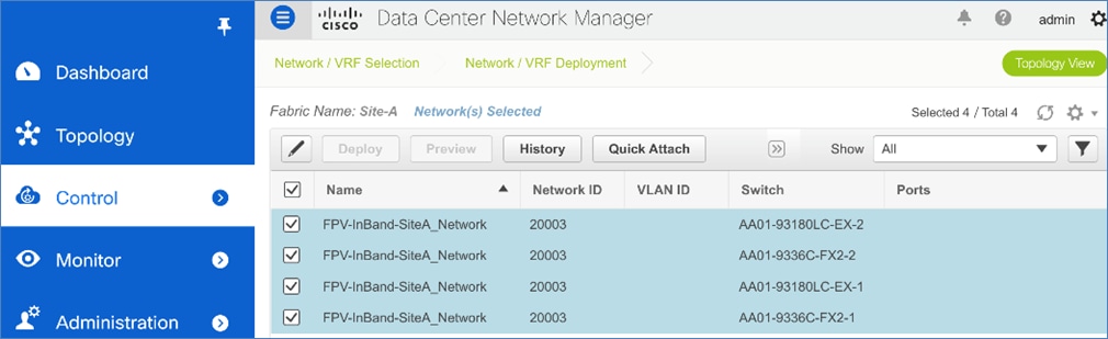
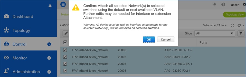
7. Click the Detailed View button. Select the Leaf switches where these networks need to be deployed. Click the Quick Attach button. Click OK.
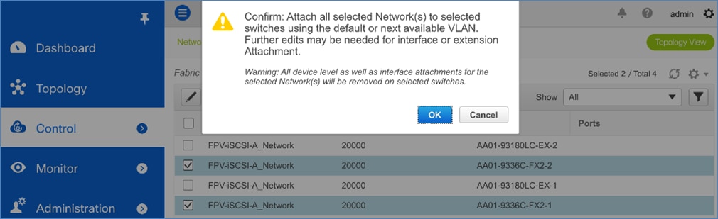
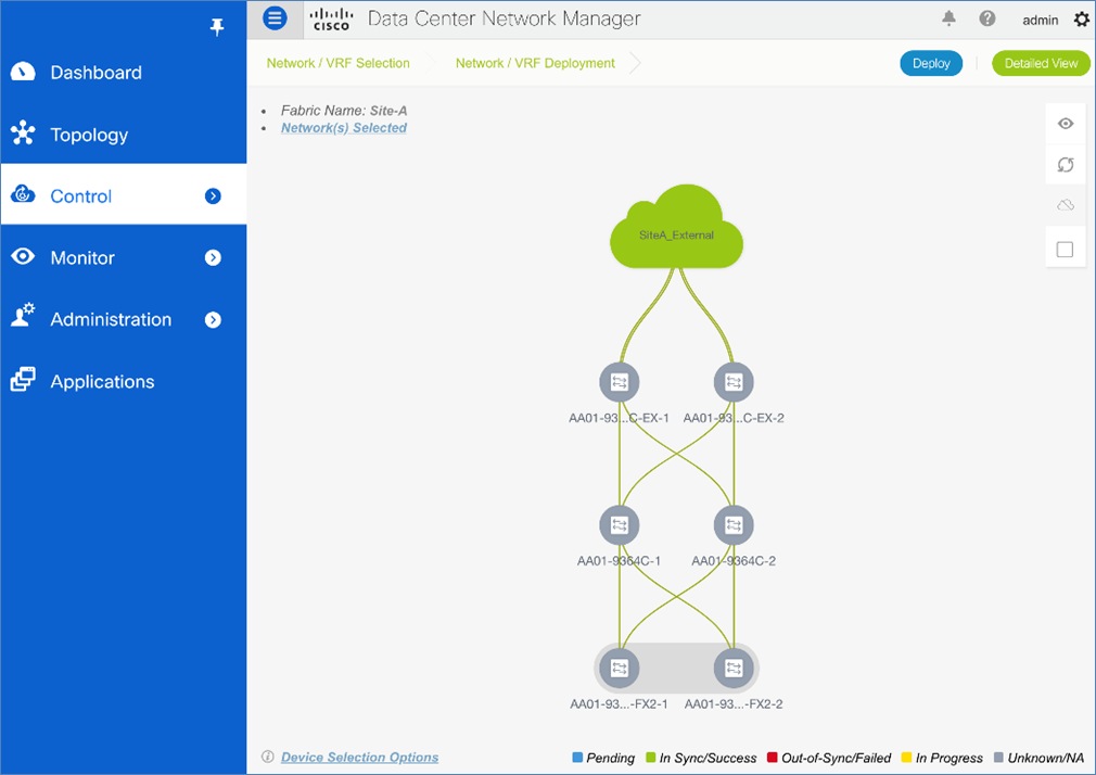
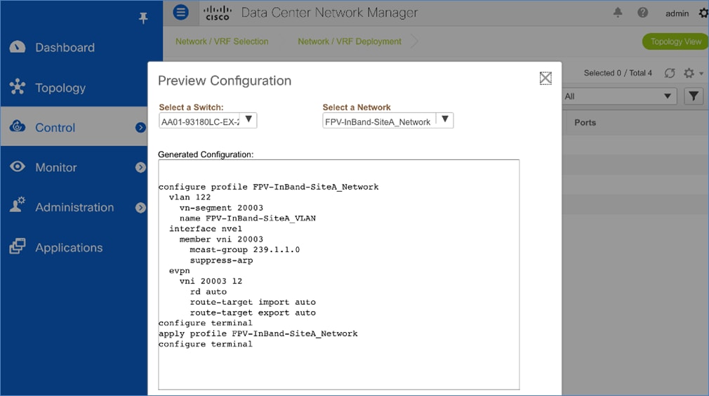
8. Click Preview to view pending changes. Click the X to close the window.
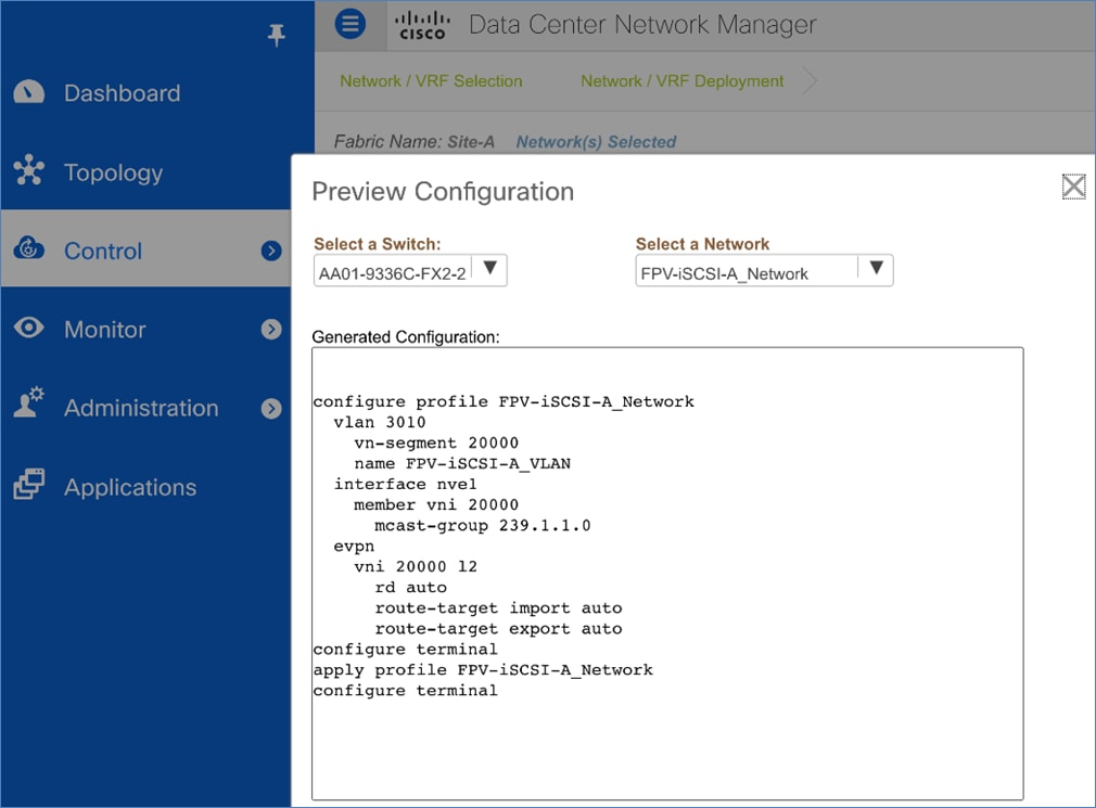
9. Click the Deploy button. The status should go from PENDING to DEPLOYED in the Status column for the two Leaf switches. Scroll to the right as needed to see all columns in this view.

10. Repeat steps 1-9 to deploy the second iSCSI network.
11. Click Deploy to deploy the configuration. The status should go from PENDING to IN PROGRESS to DEPLOYED in the Status column for the two Leaf switches.

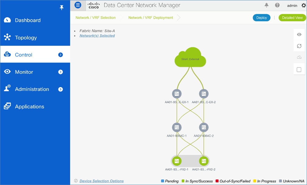
12. In the Topology View to see the where the selected network is deployed in the Site-A topology.
13. Repeat steps 1-12 to deploy the NFS network.
Deploy FlexPod In-Band Management Network
The FlexPod In-Band Management network is deployed in this design in Layer 3 mode where the traffic is Layer 3 forwarded by the fabric and the gateway is a distributed anycast gateway in the VXLAN fabric. This is unlike the previous storage networks that are deployed in Layer 2 Only mode with no gateway defined in the fabric.
1. Use a browser to navigate to Cisco DCNM’s GUI. Log in using an administrator account.
2. From the left navigation bar, select Control > Fabrics > Networks.
3. Click on the [+] icon to deploy a new Tenant network for the FlexPod infrastructure traffic. Specify a Network Name, VRF Name. In this deployment, we are specifying the VLAN ID we specifically want to use but you can optionally let DCNM pick up one from the defined pool in Fabric Settings. Specify a VLAN ID. In the Network Profile > General section of the window, specify a IPv4 Gateway/Network, VLAN Name, Interface Description and MTU. Leave everything else as-is.
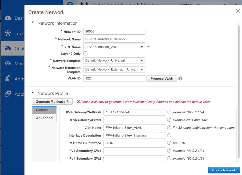
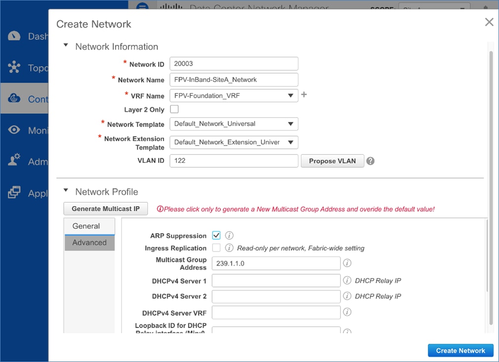
4. In the Network Profile > Advanced section of the window, enable ARP Suppression. Leave everything as-is.
5. Click the Create Network button.
6. Click the Continue button. Click the Detailed View button.

7. Select the Leaf switches where these networks need to be deployed. Click the Quick Attach button.
8. Click OK.
9. Click the Preview button to view pending changes. Click the X to close the window.
10. Click the Deploy button.

11. Click the Topology View button to view where the selected network is deployed in the fabric topology.
Deploy FlexPod vMotion Network
The FlexPod vMotion network is deployed in this design in Layer 2 Only mode with no gateway defined in the VXLAN fabric.
1. Use a browser to navigate to Cisco DCNM’s GUI. Log in using an administrator account.
2. From the left navigation bar, select Control > Fabrics > Networks.
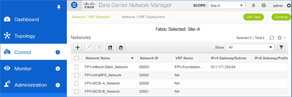
3. Click on the [+] icon to deploy a new Tenant network for the FlexPod infrastructure traffic. Specify a Network Name. Select the checkbox for Layer 2 Only mode. Specify a VLAN ID. In the Network Profile > General section, specify a VLAN name. Leave everything else as-is.
4. In the Network Profile > Advanced section, leave everything as-is.
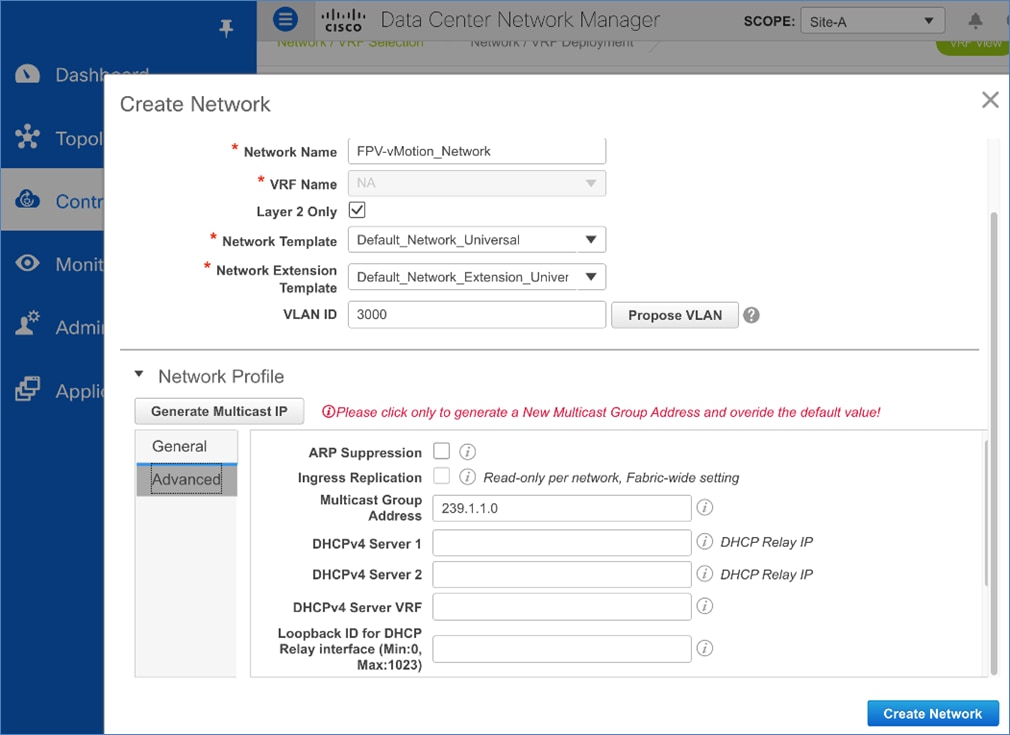
5. Click the Create Network button.
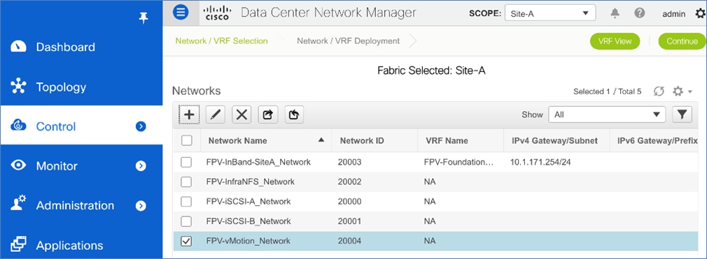
6. Click the Continue button.
7. Click the Detailed View button. Select the Leaf switches where these networks need to be deployed. Click the Quick Attach button.
8. Click OK.
9. Click the Preview button to view pending changes. Click the X to close the window.
10. Click the Deploy button. The status should go from PENDING to IN PROGRESS to DEPLOYED in the Status column for the two Leaf switches. Scroll to the right as needed to see all columns in this view. Click the Topology View button.

11. In the Topology View to see the where the selected network is deployed in the Site-A topology.
Deploy FlexPod Infrastructure Network for Common Services
The FlexPod Common Services network is deployed in this design in Layer 3 mode where the traffic is Layer 3 forwarded by the fabric and the gateway is a distributed anycast gateway in the VXLAN fabric. This network is used to host common infrastructure services such as VMware vCenter.
To deploy the FlexPod infrastructure network for Common Services, follow these steps:
1. Use a browser to navigate to Cisco DCNM’s GUI. Log in using an administrator account.
2. From the left navigation bar, select Control > Fabrics > Networks.
3. Click on the [+] icon to deploy a new Tenant network for the FlexPod infrastructure traffic. Specify a Network Name, VRF Name. In this deployment, we are specifying the VLAN ID we specifically want to use but you can optionally let DCNM pick up one from the defined pool in Fabric Settings. Specify a VLAN ID. In the Network Profile > General section of the window, specify a IPv4 Gateway/Network, VLAN Name, Interface Description and MTU. Leave everything else as-is.
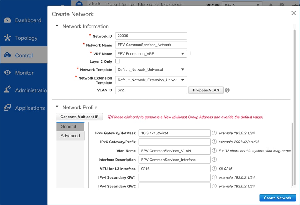
4. In the Network Profile > Advanced section of the window, enable ARP Suppression. Leave everything as-is.
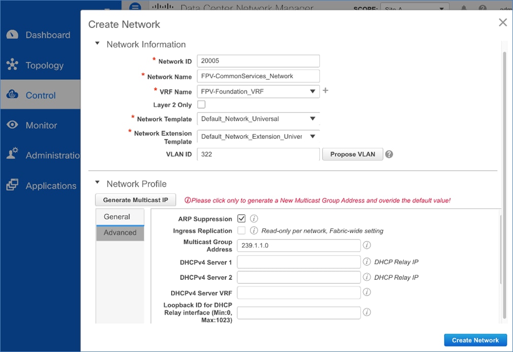
5. Click the Create Network button. Click the Continue button.
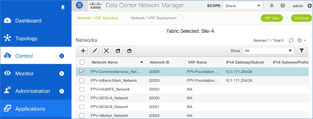
6. Click the Detailed View button.
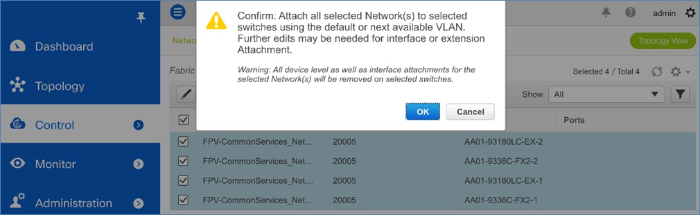
7. Select the Leaf switches where these networks need to be deployed. Click the Quick Attach button.
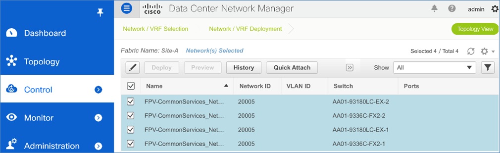
8. Click OK.
9. Click the Preview button to view pending changes. Click the X to close the window.
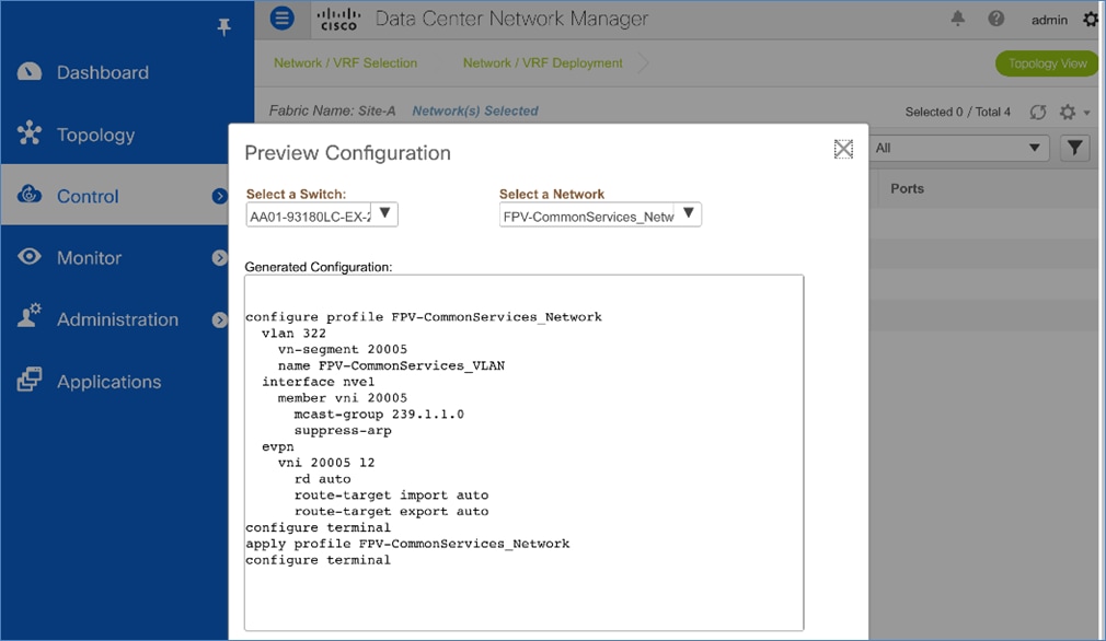
10. Click the Deploy button. Verify the status is DEPLOYED. Scroll to the right as needed to see all columns in this view.

11. Click the Topology View button to view where the selected network is deployed in the fabric topology.
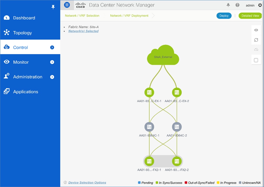
Enable Access-Layer Connectivity to FlexPod Infrastructure Networks
To enable FlexPod infrastructure networks on access-layer connections to Cisco UCS domain and NetApp storage cluster, complete the steps outlined in the upcoming sections.
Enable Infrastructure Networks on Access-Layer Connections to Cisco UCS Domain
To enable infrastructure networks on the access-layer connections to Cisco UCS domain, follow these steps:
1. Use a browser to navigate to Cisco DCNM’s GUI. Log in using an administrator account.
2. From the left navigation bar, select Control > Fabrics > Networks. Click OK to exit any pop-ups that come up. Select the correct scope in the drop-down list next to Scope: in the top-right corner of the window.
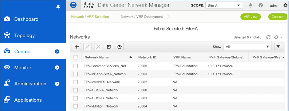
3. Select the networks that need to be enabled on the access-layer connection to Cisco UCS Domain. All networks are selected in this case. Click the Continue button.
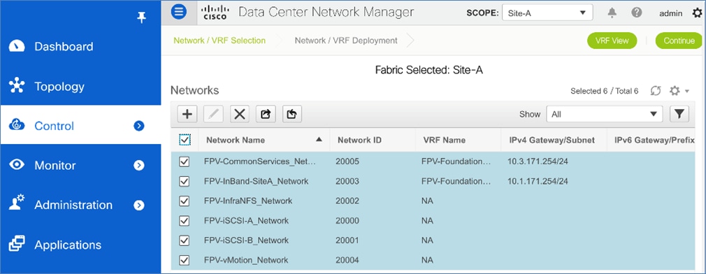
4. Click the Detailed View button.
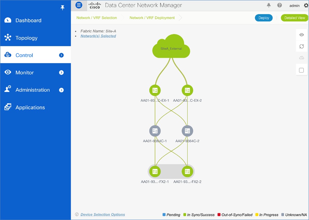
5. Select Quick Filter from the drop-down list next to Show from the top menu. This will expose the filter box above every column.
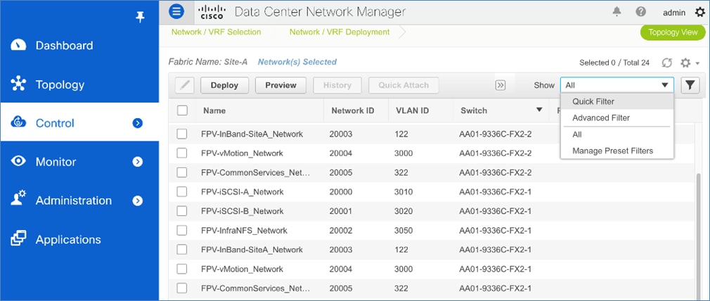
6. Filter based on the access-layer leaf switch that connects to the Cisco UCS Domain. Select the first switch in the vPC pair to the Cisco UCS domain. Select all networks that need to be deployed. Click on the pencil icon to edit the previously deployed networks on the first leaf switch in the vPC pair.
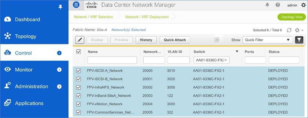
7. You should see a network tab for each network and both leaf switches listed though only one switch was selected in the previous. This is because the switches are part of a vPC pair – a configuration that gets applied to one will get applied to both. Note the box ![]() in the Interfaces column.
in the Interfaces column.
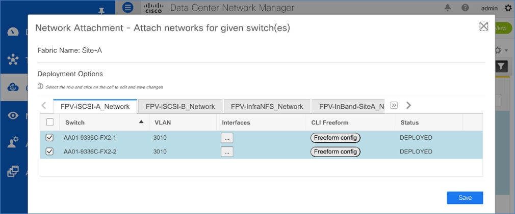
8. For the first network, click the box ![]() in the Interfaces column next to the first switch listed in the leaf switch pair.
in the Interfaces column next to the first switch listed in the leaf switch pair.
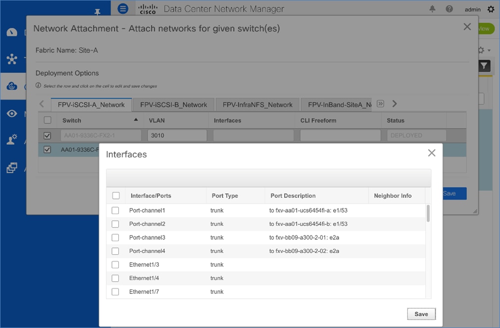
9. In the Interfaces pop-up window, select both port-channels that go to both Cisco UCS Fabric Interconnects in the Cisco UCS Domain.
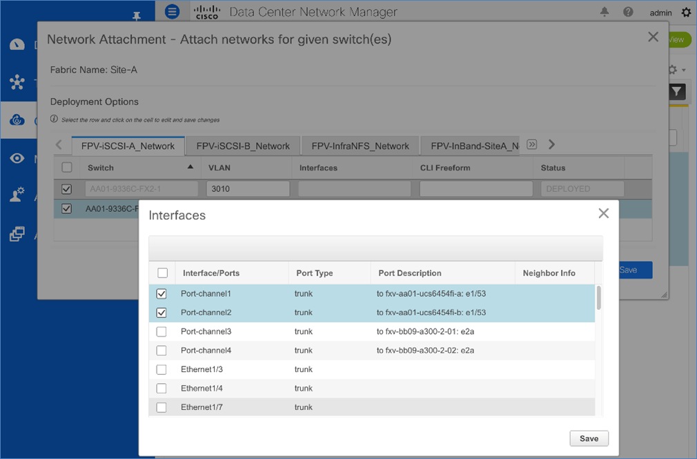
10. Click Save. Note that the interfaces are now populated for the first switch. Click Save again.

11. The first network for the first switch now lists the Ports and the Status is now PENDING. Click the pencil icon again.

12. You will now see that the port/interface information is now populated for both leaf switches though the configuration was only done for one switch. Cisco DCNM automatically configures both leaf switches in the same leaf switch vPC pair.
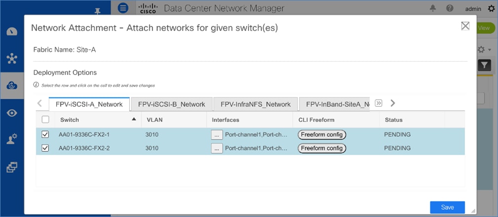
13. For each network tab, repeat steps 7-9 to enable these networks on the access-layer connections to Cisco UCS Domain. Click Save. All switches are now in PENDING state. If you click on the pencil icon again, you will see that the ports or interfaces for the peer leaf switches are now configured as well.

14. Deselect the checkbox next to all switches. Click the Preview button. Note that all networks/VLANs are being enabled on the access layer connections to Cisco UCS domain. Click the X to close the Preview window.
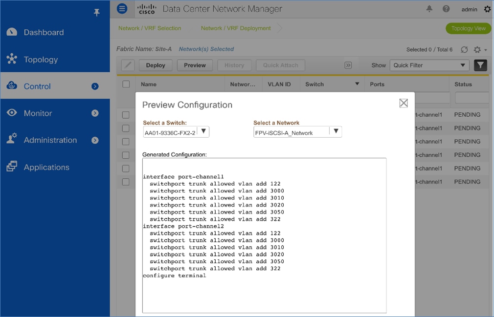
15. Click the Deploy button. The status should change from PENDING to IN PROGRESS to DEPLOYED.
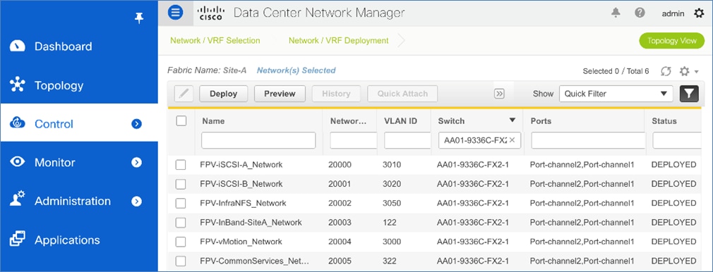
Enable Infrastructure Networks on Access-Layer Connections to NetApp Storage Cluster
To enable infrastructure networks on the access-layer connections to the NetApp storage cluster, follow these steps:
1. Repeat steps 1-5 from the previous section. However, select the following infrastructure networks from the list below that needs to be enabled on the access-layer connection to the NetApp storage cluster.
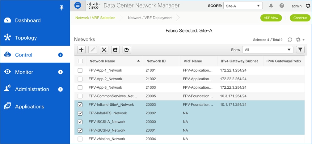
2. Filter on the first leaf switch in the vPC pair to the NetApp Storage cluster.
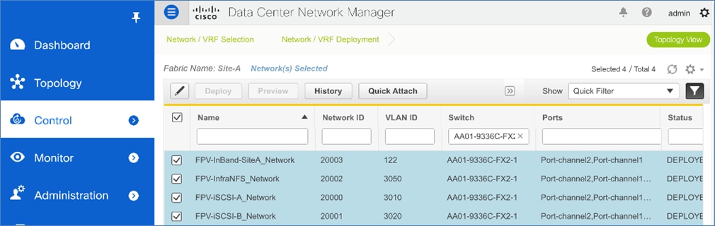
3. Click on the pencil icon from the menu.
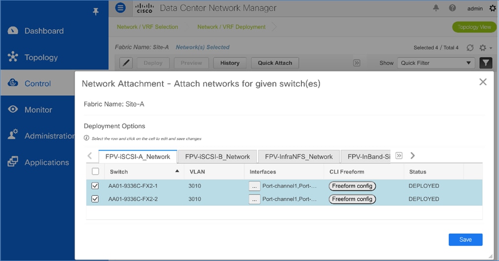
4. For the first network, click the box ![]() in the Interfaces column next to the first switch listed in the leaf switch pair. Select the Interfaces/Ports that connect to the NetApp Storage cluster. In this case, two port-channels going to Cisco UCS domain were already configured for these networks – however, two additional port-channels going to NetApp had to be selected in this step.
in the Interfaces column next to the first switch listed in the leaf switch pair. Select the Interfaces/Ports that connect to the NetApp Storage cluster. In this case, two port-channels going to Cisco UCS domain were already configured for these networks – however, two additional port-channels going to NetApp had to be selected in this step.
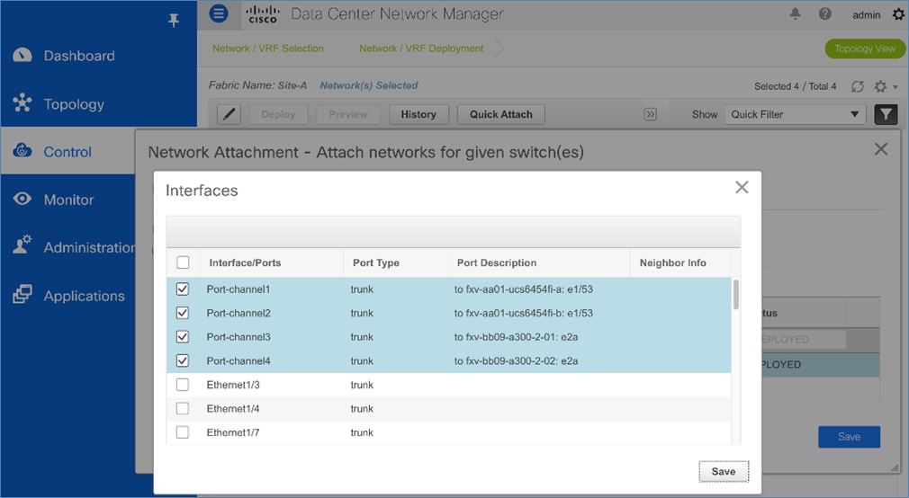
5. Click Save.
6. Repeat steps 4-5 for each network tab. Click Save. Note that the status of these networks are in PENDING state at this stage. Scroll to the right as needed to see all columns available in this view.
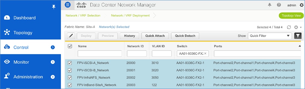
7. Deselect all networks. Click the Preview button to see the pending changes. Click the X to close the window.
8. Click the Deploy button. The status should go from PENDING to IN PROGRESS to DEPLOYED. Scroll to the right as needed to see all columns available in this view.
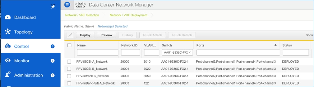
Enable External Connectivity for FlexPod Infrastructure Networks
To enable access to external/outside networks from the FlexPod infrastructure tenant, follow these steps:
1. Use a browser to navigate to Cisco DCNM’s GUI. Log in using an administrator account.
2. From the left navigation bar, select Control > Fabrics > VRFs. Click OK to exit any pop-ups that come up. Select the correct scope in the drop-down list next to Scope: in the top-right corner of the window. Select the Tenants that need access to external or outside networks. Click the Continue button.
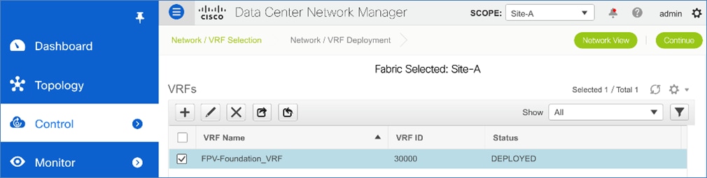
3. Click the Detailed View button.
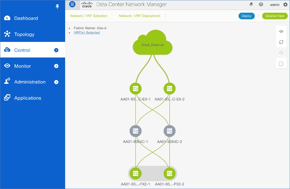
4. Select and click the arrow on the Switch column to sort based on hostname. Select the two border switches that provide connectivity to external/outside networks. Click on the pencil icon to edit the Tenant VRF.
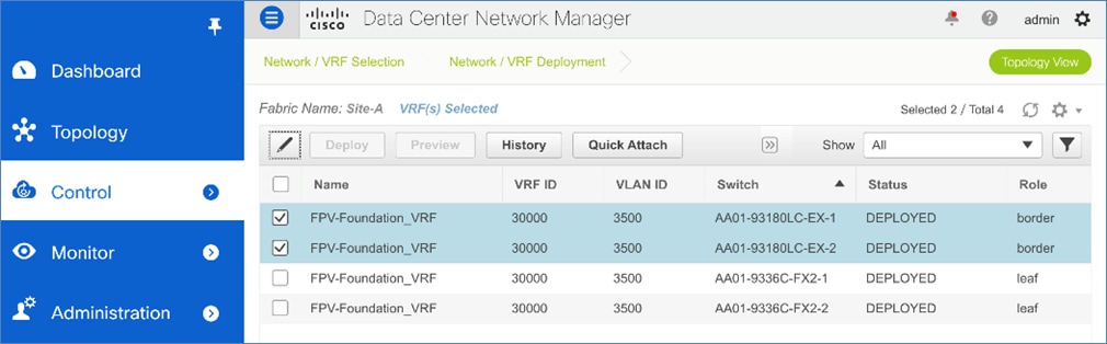
5. In the VRF Extension Attachment – Attach extensions pop-up window, click on the icon in the Extend column for the first Border switch. Scroll to the right as needed to see all columns available in this view.
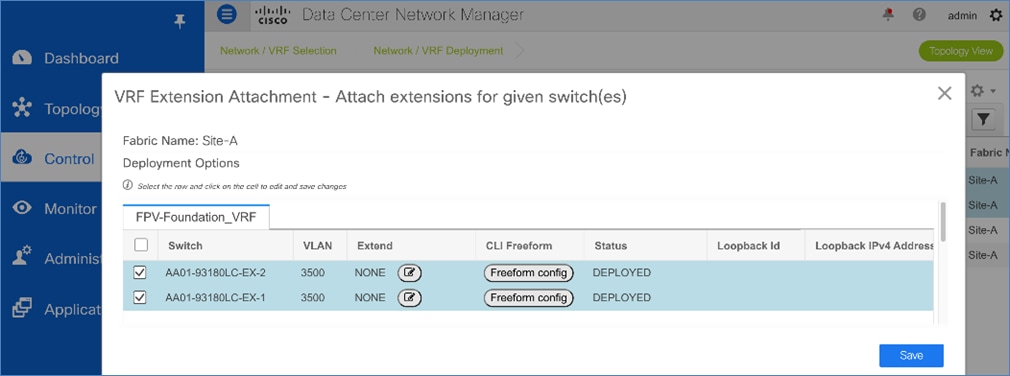
6. From the Extend column, select VRF-Lite from the drop-down list.
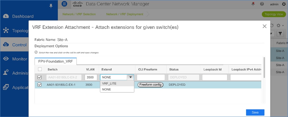
7. The window will now expand to include the interfaces that can be used to extend the VRF using VRF-Lite to the External Gateway. In the Extension Details section, select all relevant switches and interfaces where the VRF should be extended. Scroll to the right as needed to see all columns available in this view.
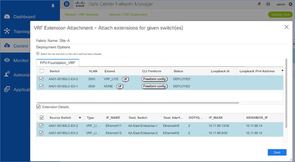
8. From the PEER_VRF_NAME column, specify the name that should be used for the VRF in the External Gateway switch that connects to this Border switch. Repeat this step for each Border switch in the list.
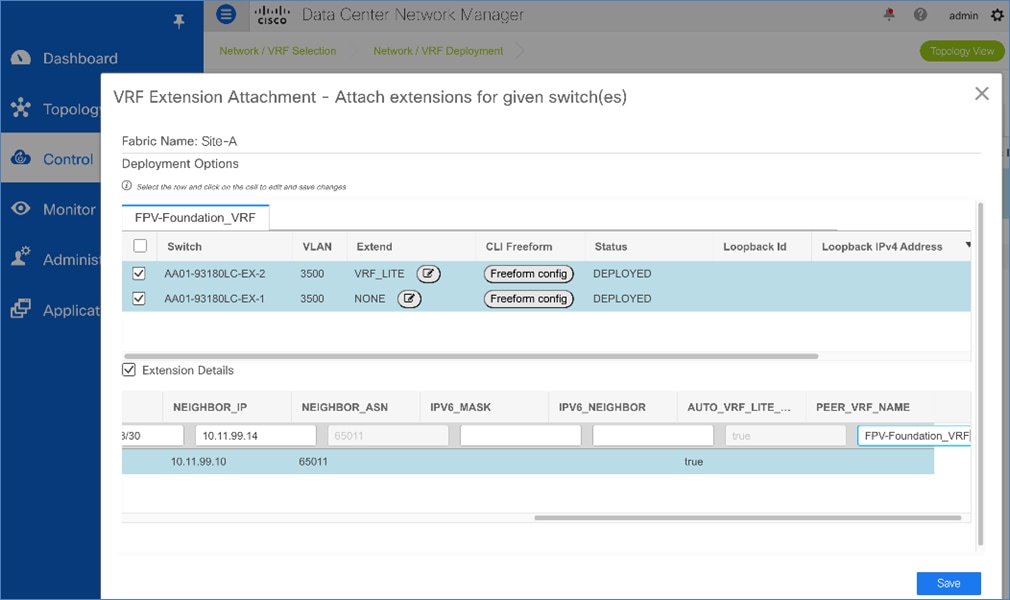
9. Repeat steps 5-8 for the second Border switch in the list.
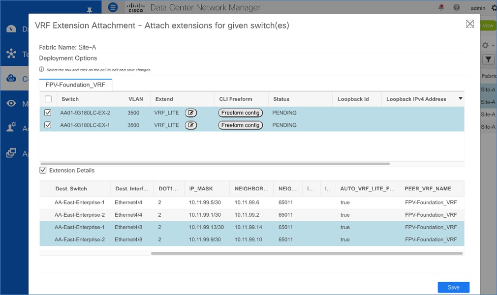
10. Click Save. The VRF configuration on the Border switches are now in a PENDING state.
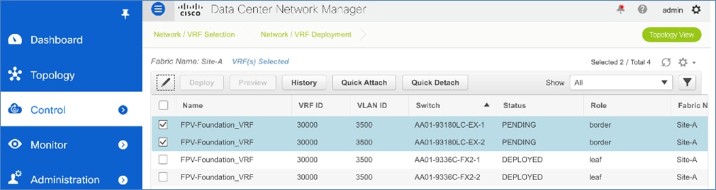
11. Deselect both Border switches. Click the Preview button to view the pending configuration changes.
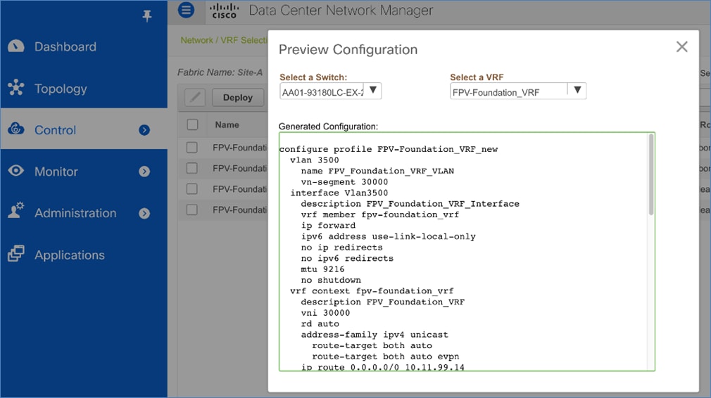
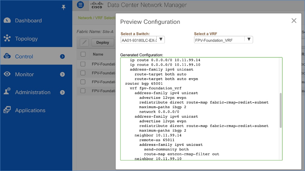
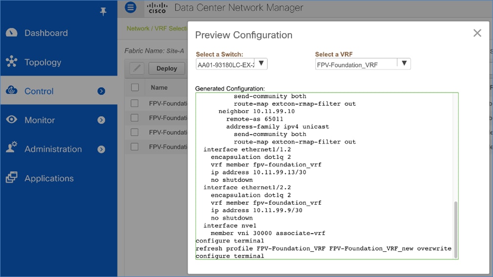
12. Click the X to close the Preview window. Click the Deploy button. The Status column should go from PENDING to IN PROGRESS to DEPLOYED.
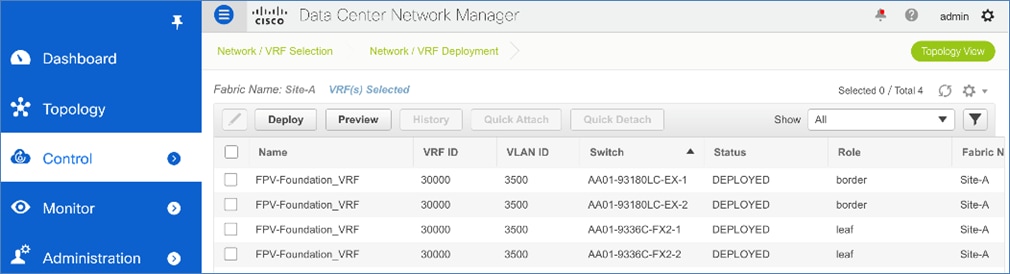
13. From the left navigation bar, select Control > Fabrics > Fabric Builder.
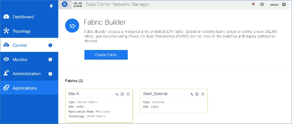
14. Select the external fabric from the list. Note that the external gateways are Out-of-Sync/Failed state.
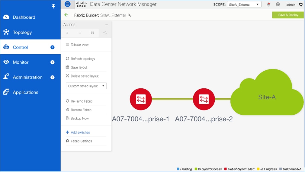
15. Click the Save & Deploy button. Note that there are ’30 lines’ of changes.
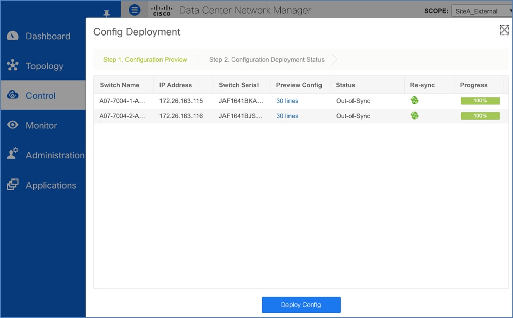
16. Click on the ’30 lines’ to preview the pending changes.
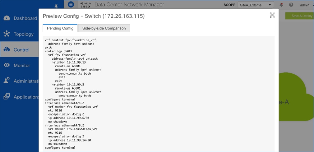
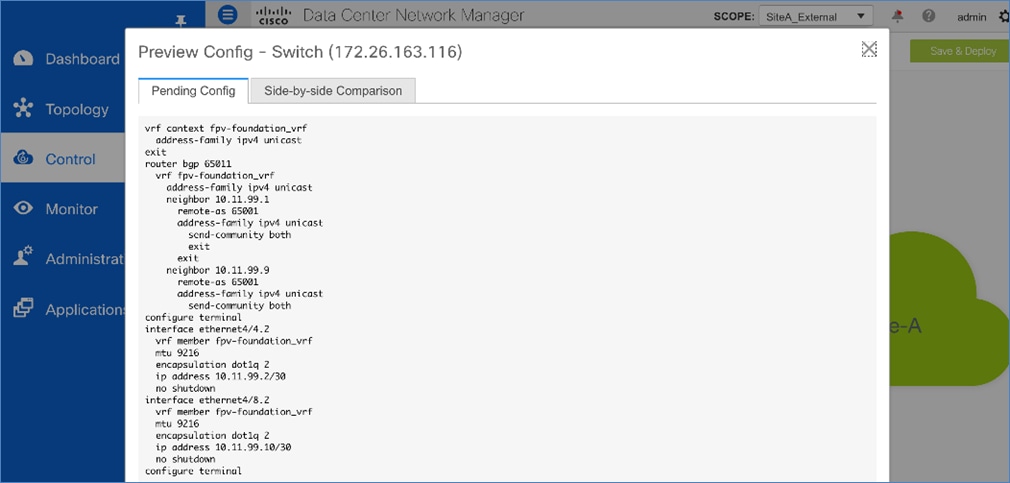
17. Click the X to close the Preview window. Click the Deploy Config button.
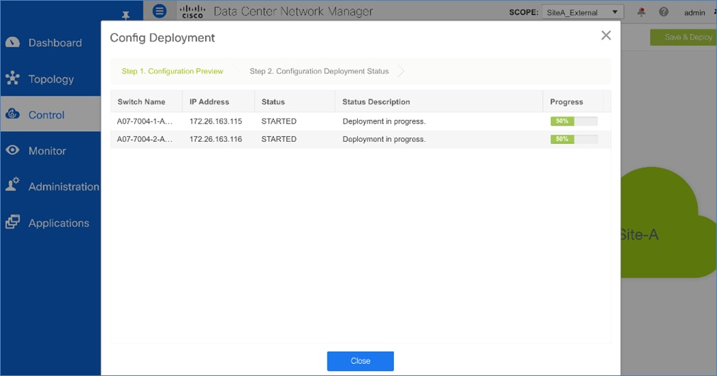
18. When the deployment completes and the Status is COMPLETED, click the Close button to close the Config Deployment pop-up window.
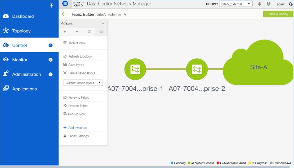
19. The external fabric switches are back to an In Sync/Success state.
Enable Network Connectivity for FlexPod Applications
In this design, Applications are deployed in a dedicated Tenant, separate from the FlexPod infrastructure Tenant. To enable access to FlexPod Application Tenant VMs hosted on the FlexPod infrastructure, the Application Tenant and networks must be first deployed in the VXLAN fabric. In this design, the FlexPod Application traffic is part a separate tenant/VRF (FPV-Application_VRF), dedicated to Application traffic. This tenant is used by the applications workloads hosted on the FlexPod Virtual Server Infrastructure (VSI).
Setup Information
The configuration parameters for deploying the FlexPod infrastructure networks in Site-A datacenter fabric are provided below.
Table 15. Data Center Information
| Scope |
Site-A |
Table 16. Application Tenant/VRF
| VRF Name |
VRF VLAN Name |
VRF Interface Description |
VRF Description |
| FPV-Application_VRF |
FPV_Application_VRF_VLAN |
FPV_Application_VRF_Interface |
FPV_Application_VRF |
Table 17. Application Networks (FPV-Application_VRF)
| VLAN Name |
VLAN |
VLAN Name |
Forwarding |
IP Subnet/Gateway* |
VXLAN Network ID (VNID) |
Notes |
| FPV-App-1_Network |
1001 |
FPV-App-1_VLAN FPV-App-1_Interface |
Layer 3 |
172.22.1.254/24 |
21001 |
MTU = 9216 |
| FPV-App-2_Network |
1002 |
FPV-App-2_VLAN FPV-App-2_Interface |
Layer 3 |
172.22.2.254/24 |
21002 |
MTU = 9216 |
| FPV-App-3_Network |
1003 |
FPV-App-3_VLAN FPV-App-3_Interface |
Layer 3 |
172.22.3.254/24 |
21003 |
MTU = 9216 |
* Gateway IP is specified only for L3 Forwarding and when the default gateway is in the VXLAN Fabric
Table 18. Application Storage Networks (FPV-Application_VRF)
| Network Name |
VLAN |
VLAN Name |
Forwarding |
IP Subnet /Gateway* |
VXLAN Network ID (VNID) |
Notes |
| FPV-App1-NFS_Network |
3051 |
FPV-App1-NFS_VLAN |
Layer 2 Only |
192.168.51.0/24 |
21004 |
App-1 NFS |
| FPV-App2-iSCSI-A_Network |
3012 |
FPV-App2-iSCSI-A_VLAN |
Layer 2 Only |
192.168.12.0/24 |
21005 |
App-2 iSCSI |
| FPV-App2-iSCSI-B_Network |
3022 |
FPV-App2-iSCSI-B_VLAN |
Layer 2 Only |
192.168.22.0/24 |
21006 |
App-2 iSCSI |
| FPV-App3-NFS_Network |
3053 |
FPV-App3-NFS_VLAN |
Layer 2 Only |
192.168.53.0/24 |
21007 |
App-3 NFS |
| FPV-App3-iSCSI-A_Network |
3013 |
FPV-App3-iSCSI-A_VLAN |
Layer 2 Only |
192.168.13.0/24 |
21008 |
App-3 iSCSI |
| FPV-App3-iSCSI-B_Network |
3023 |
FPV-App3-iSCSI-B_VLAN |
Layer 2 Only |
192.168.23.0/24 |
21009 |
App-3 iSCSI |
* Gateway IP is specified only for L3 Forwarding and when the default gateway is in the VXLAN Fabric
Deploy FlexPod Application Tenant in Cisco DCNM
To create the FlexPod Application Tenant in Cisco DCNM, use the Setup Information provided above to follow these steps:
1. Use a browser to navigate to Cisco DCNM’s GUI. Log in using an administrator account.
2. From the left navigation bar, select Control > Fabrics > VRFs. Click OK in the pop-window that complains about an Unsupported Fabric Data Center selected. Use Scope: to change the scope to Site-A.
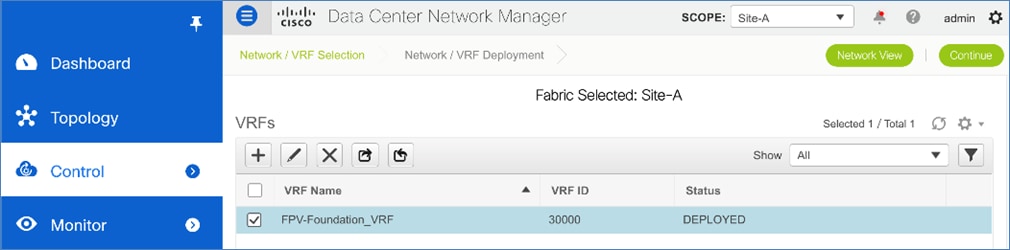
3. Click on the [+] icon to deploy a new Tenant VRF for the FlexPod infrastructure traffic. Specify a VRF VLAN Name, VRF Interface Description and VRF Description. Leave everything else as-is.
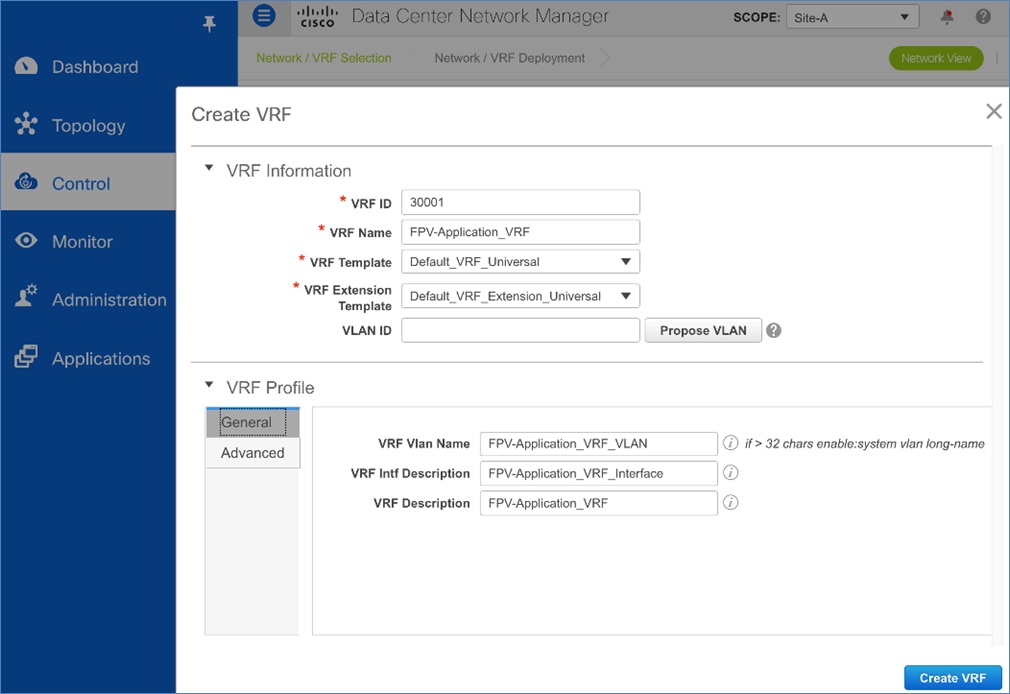
4. Click the Create VRF button. A small pop-up box will appear in the bottom-right corner to confirm that the VRF was created successfully.
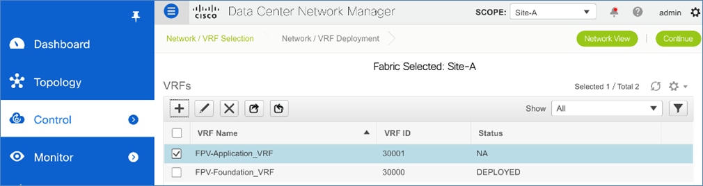
5. Click the Continue button.

6. Click the Detailed View button.
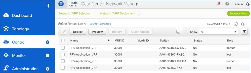
7. Select the checkbox for all Leaf and Border switches in the list. Click the Quick Attach button.
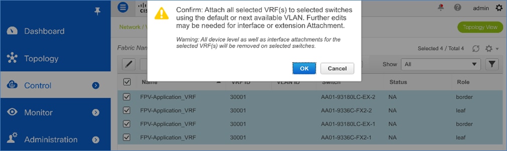
8. Click OK.
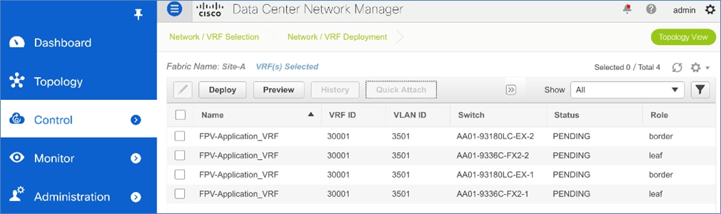
9. Click the Preview button to preview the pending configuration on all the Leaf and Border switches.
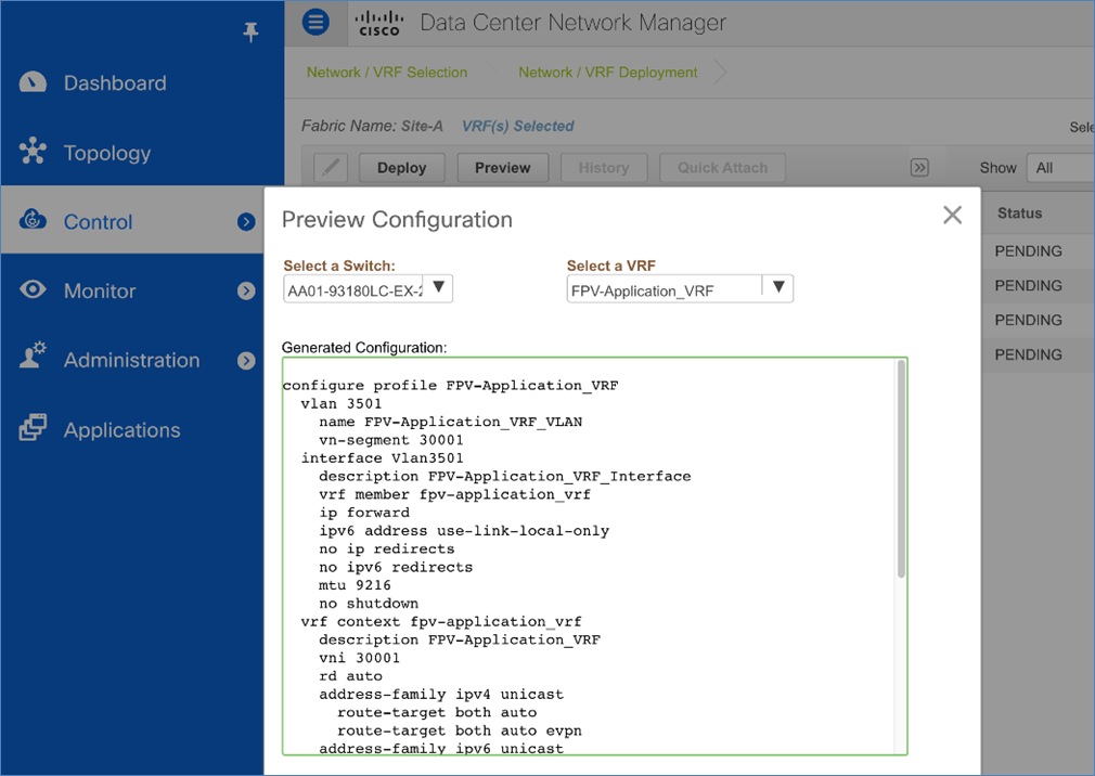
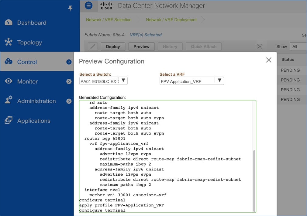
10. Click the X to close the Preview Configuration window. Click the Deploy button. Once the configuration is deployed, the Status go from PENDING to IN PROGRESS to DEPLOYED. Click the Topology View button.

11. In the Topology View to see the where the selected VRF is deployed in the Site-A topology.

Deploy FlexPod Application Networks
The Applications networks are deployed in this design in Layer 3 mode where the traffic is Layer 3 forwarded by the fabric and the gateway is a distributed anycast gateway in the VXLAN fabric.
To create the FlexPod Application Tenant networks in Cisco DCNM, use the Setup Information provided above and follow these steps:
1. Use a browser to navigate to Cisco DCNM’s GUI. Log in using an administrator account.
2. From the left navigation bar, select Control > Fabrics > Networks.
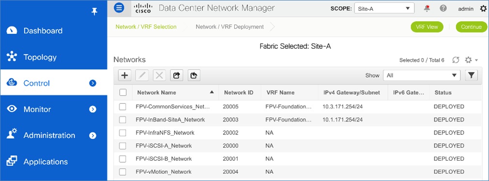
3. Click on the [+] icon to deploy a new Tenant network for the FlexPod infrastructure traffic. Specify a Network Name, VRF Name. In this deployment, we are specifying the VLAN ID we specifically want to use but you can optionally let DCNM pick up one from the defined pool in Fabric Settings. Specify a VLAN ID. In the Network Profile > General section of the window, specify a IPv4 Gateway/Network, VLAN Name, Interface Description and MTU. Leave everything else as-is.
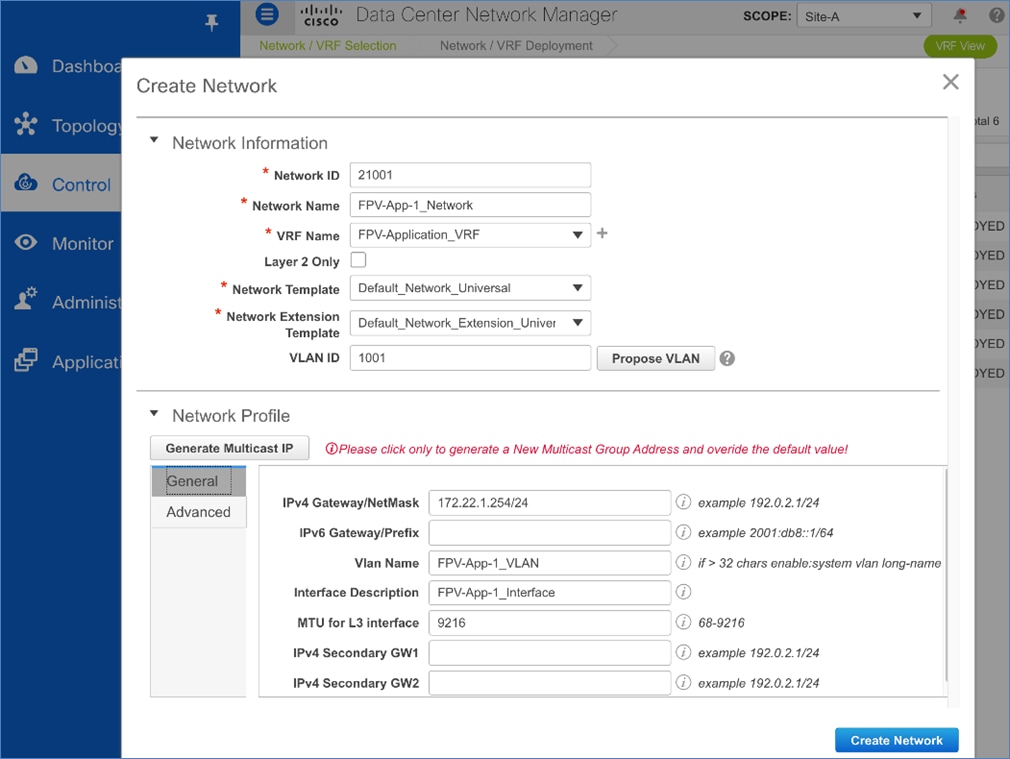
4. In the Network Profile > Advanced section of the window, enable ARP Suppression. Leave everything as-is.
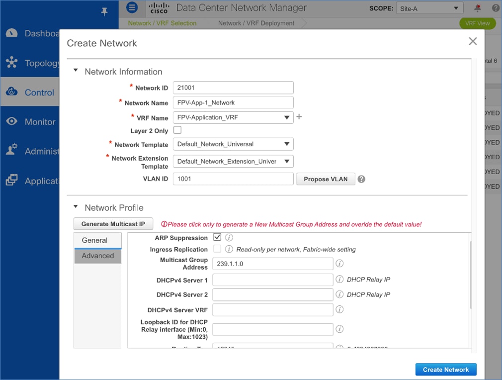
5. Click the Create Network button.
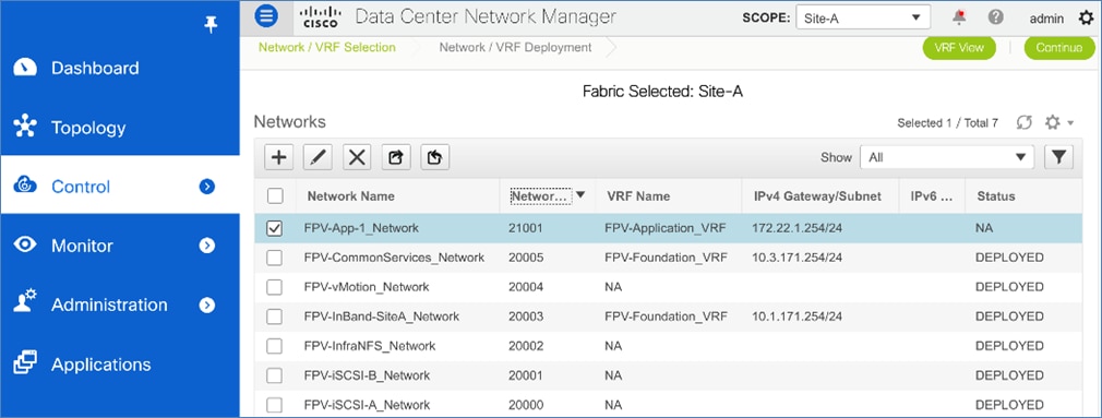
6. Click the Continue button.
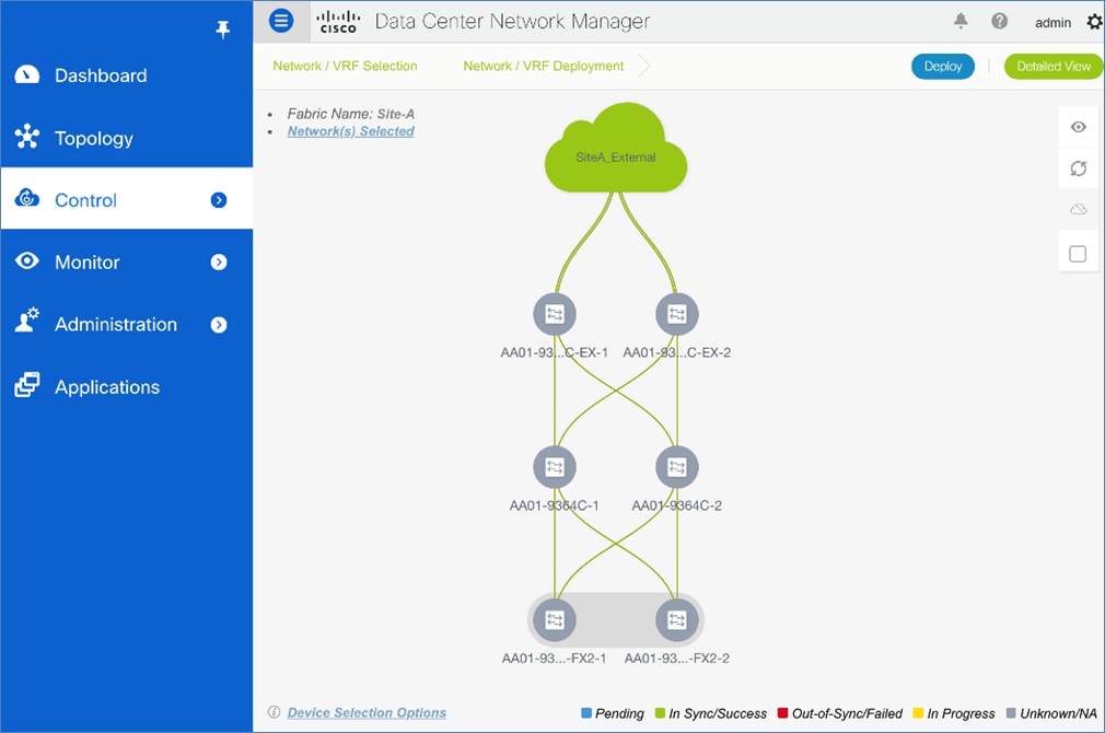
7. Click the Detailed View button. Select the Leaf switches where these networks need to be deployed. Click the Quick Attach button. You can decide which switches to deploy this network on.
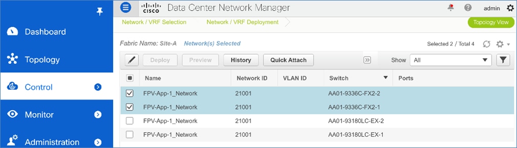
8. Click OK.
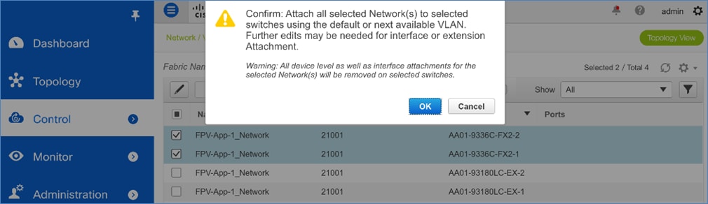
9. Click the Preview button to view pending changes.
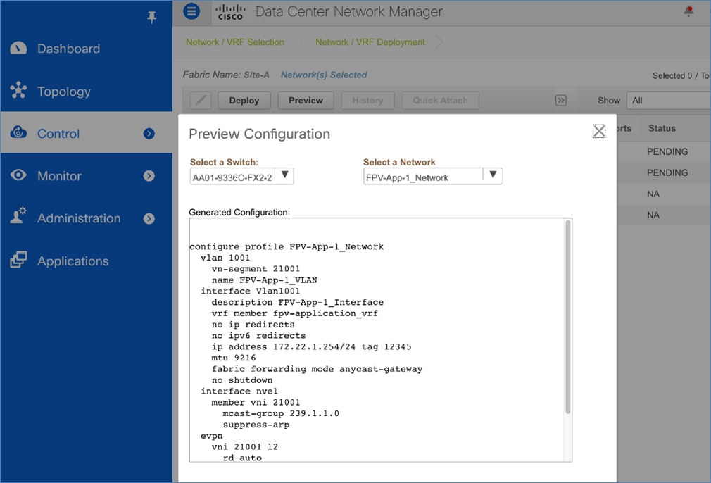
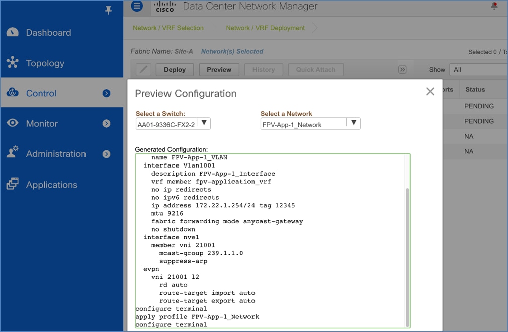
10. Click X to close the Preview window. Click the Deploy button.
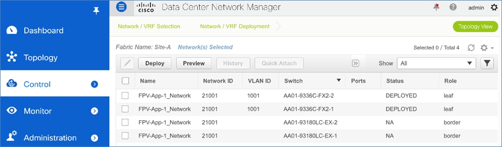
11. Click the Topology View button to view where the selected network is deployed in the fabric topology.
12. Repeat steps 1-11 to deploy remaining Application networks.
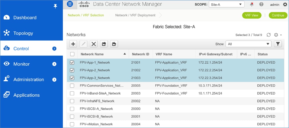
Enable Access-Layer Connectivity to FlexPod Application Networks
To enable FlexPod Application networks on access-layer connections to Cisco UCS domain and NetApp storage cluster, complete the steps outlined in the upcoming sections.
Enable Application Networks on Access-Layer Connections to Cisco UCS Domain
To enable FlexPod Applications networks on the access-layer connections to Cisco UCS domain, follow these steps:
1. Use a browser to navigate to Cisco DCNM’s GUI. Log in using an administrator account.
2. From the left navigation bar, select Control > Fabrics > Networks. Click OK to exit any pop-ups that come up. Select the correct scope in the drop-down list next to Scope: in the top-right corner of the window. Select the networks that need to be enabled on the access-layer connection to the Cisco UCS Domain.

3. Click the Continue button. Click the Detailed View button.
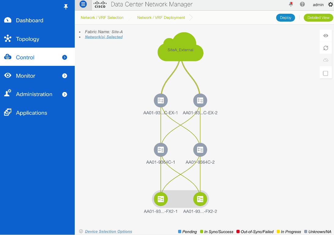
4. Select Quick Filter from the drop-down list next to Show from the top menu. This will expose the filter box above every column. Filter based on the access-layer leaf switch that connects to the Cisco UCS Domain. Select the first switch in the vPC pair to the Cisco UCS domain. Select all networks that need to be deployed. Click on the pencil icon to edit the previously deployed networks on the first leaf switch in the vPC pair.

5. You should see a network tab for each network and both leaf switches listed though only one switch was selected in the previous. This is because the switches are part of a vPC pair – a configuration that gets applied to one will get applied to both. Note the box ![]() in the Interfaces column.
in the Interfaces column.
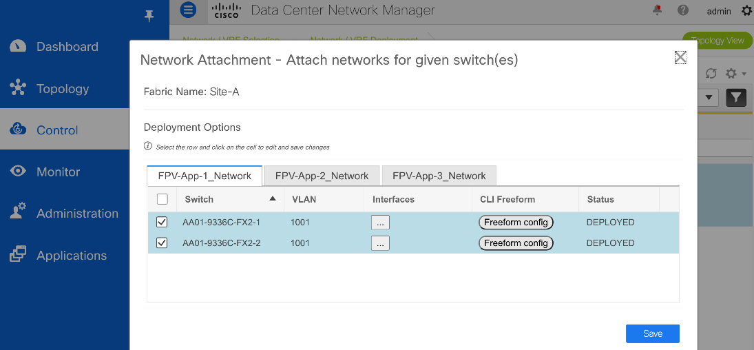
6. In the first network tab, click the box ![]() in the Interfaces column next to the first switch listed. In the Interfaces pop-up window, select both port-channels that go to both Cisco UCS Fabric Interconnects in the Cisco UCS Domain.
in the Interfaces column next to the first switch listed. In the Interfaces pop-up window, select both port-channels that go to both Cisco UCS Fabric Interconnects in the Cisco UCS Domain.
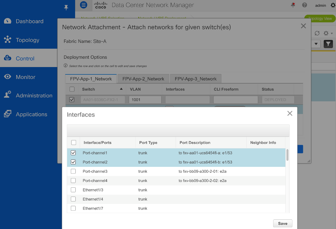
7. Click Save. Note that the interfaces are now populated for the first switch. Click Save again. The first network for the first switch now lists the Ports and the Status is now PENDING.
8. Click the pencil icon again.
9. You will now see that the port/interface information is now populated for both leaf switches though the configuration was only done for one switch. Cisco DCNM automatically configures both leaf switches in the same leaf switch vPC pair.
10. For each network tab, repeat steps 7-9 to enable these networks on the access-layer connections to Cisco UCS Domain. Click Save. All switches are now in PENDING state. If you click on the pencil icon again, you will see that the ports or interfaces for the peer leaf switches are also configured now.
11. Deselect the checkbox next to all switches. Click the Preview button. Note that all networks/VLANs are being enabled on the access layer connections to Cisco UCS domain. Click the X to close the Preview window.
12. Click the Deploy button. The status should change from PENDING to IN PROGRESS to DEPLOYED.
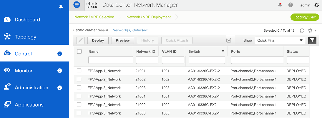
Enable Applications Networks on Access-Layer Connections to NetApp Storage Cluster
To enable FlexPod Applications networks on the access-layer connections to the NetApp storage cluster, follow these steps:
1. Repeat steps 1-5 from the previous section.
2. Filter on the first leaf switch in the vPC pair to the NetApp Storage cluster.
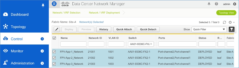
3. Click on the pencil icon from the menu.
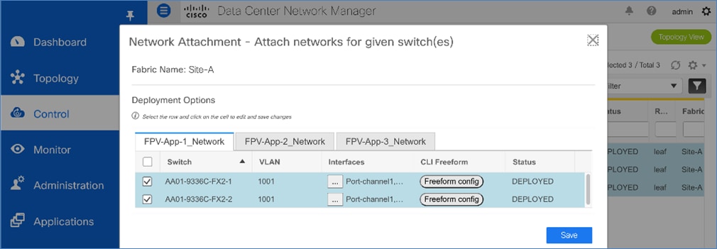
4. For the first network, click the box ![]() in the Interfaces column next to the first switch listed in the leaf switch pair. Select the Interfaces/Ports that connect to the NetApp Storage cluster. In this case, two port-channels going to Cisco UCS domain were already configured for these networks – however, two additional port-channels going to NetApp had to be selected in this step.
in the Interfaces column next to the first switch listed in the leaf switch pair. Select the Interfaces/Ports that connect to the NetApp Storage cluster. In this case, two port-channels going to Cisco UCS domain were already configured for these networks – however, two additional port-channels going to NetApp had to be selected in this step.
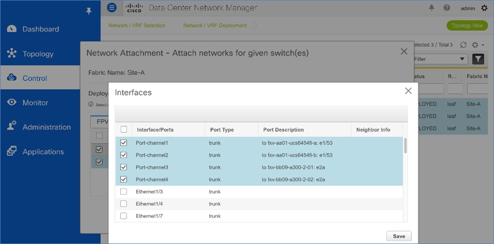
5. Click Save.
6. Repeat steps 4-5 for each network tab. Click Save. Note that the status of these networks are in PENDING state at this stage. Scroll to the right as needed to see all columns available in this view.
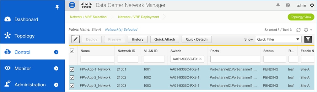
7. Deselect all networks. Click the Preview button to see the pending changes. Click the X to close the window.
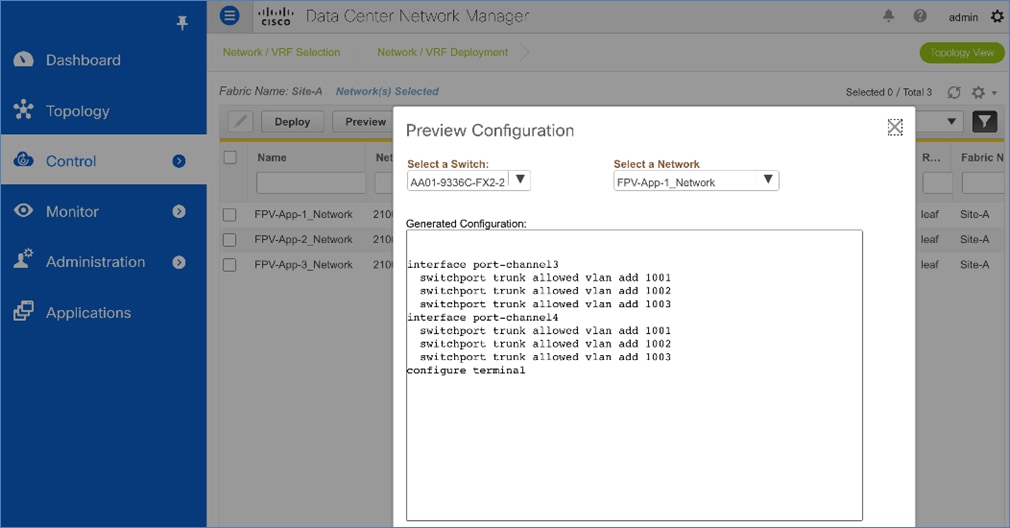
8. Click the Deploy button. The status should go from PENDING to IN PROGRESS to DEPLOYED. Scroll to the right as needed to see all columns available in this view.
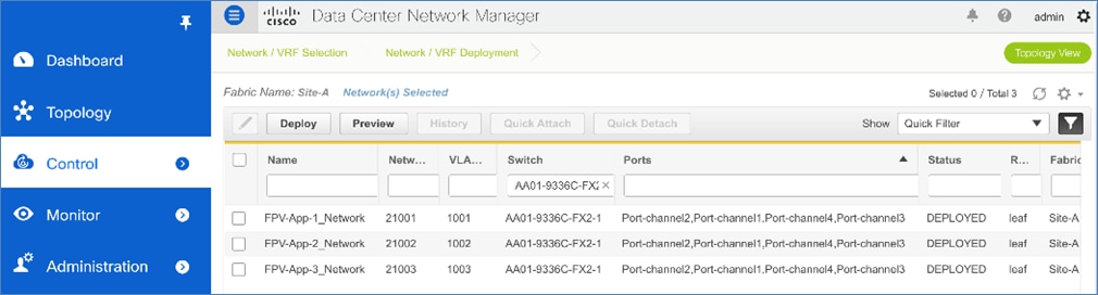
Deploy FlexPod Application Storage Networks
The FlexPod Applications deployed in the Application Tenant (FPV-Application-Tenant) may require storage access to iSCSI or NFS volumes hosted on the NetApp cluster. In this deployment, the storage networks shown in Table 18 are deployed.
To deploy storage access for the Applications hosted on the FlexPod infrastructure, follow these steps:
1. Deploy Application storage networks from Cisco DCNM using the setup information in Table 18 – use the procedures outlined here.
2. Enable Application storage networks on the access-layer connection to Cisco UCS Domain - use the procedures outlined here.
3. Enable Application storage networks on the access-layer connection to NetApp Storage - use the procedures outlined here.
NetApp All Flash FAS A300 Controllers
See the following section (NetApp Hardware Universe) for planning the physical location of the storage systems:
● Site Preparation
● System Connectivity Requirements
● Circuit Breaker, Power Outlet Balancing, System Cabinet Power Cord Plugs, and Console Pinout Requirements
● AFF Series Systems
To confirm that the hardware and software components that you would like to use are supported with the version of ONTAP that you plan to install, follow these steps found at the NetApp Support site.
To configure the HWU, follow these steps:
1. Access the HWU application to view the System Configuration guides. Click the Platforms menu to view the compatibility between different version of the ONTAP software and the NetApp storage appliances with your desired specifications.
2. Alternatively, to compare components by storage appliance, click Compare Storage Systems.
Follow the physical installation procedures for the controllers found in the AFF A300 Series product documentation found at the NetApp Support site.
NetApp storage systems support a wide variety of disk shelves and disk drives. The complete list of disk shelves that are supported by the AFF A300 is available found at the NetApp Support site.
When using SAS disk shelves with NetApp storage controllers, refer to the SAS cabling rules section in the AFF and FAS System Documentation Center for proper cabling guidelines.
Complete Configuration Worksheet
Before running the setup script, complete the Cluster setup worksheet in the ONTAP 9 Documentation Center. You must have access to the NetApp Support site to open the cluster setup worksheet.
Before running the setup script, review the configuration worksheets in the Software setup section of the ONTAP 9 Documentation Center to learn about configuring ONTAP. Table 18 lists the information needed to configure two ONTAP nodes. Customize the cluster-detail values with the information applicable to your deployment.
Table 19. ONTAP Software Installation Prerequisites
| Cluster Detail |
Cluster Detail Value |
| Cluster node 01 IP address |
<node01-mgmt-ip> |
| Cluster node 01 netmask |
<node01-mgmt-mask> |
| Cluster node 01 gateway |
<node01-mgmt-gateway> |
| Cluster node 02 IP address |
<node02-mgmt-ip> |
| Cluster node 02 netmask |
<node02-mgmt-mask> |
| Cluster node 02 gateway |
<node02-mgmt-gateway> |
| ONTAP 9.7 URL |
<url-boot-software> |
Configure Node 01
To configure node 01, follow these steps:
1. Connect to the storage system console port. You should see a Loader-A prompt. However, if the storage system is in a reboot loop, press Ctrl-C to exit the autoboot loop when the following message displays:
Starting AUTOBOOT press Ctrl-C to abort…
2. Allow the system to boot up.
autoboot
3. Press Ctrl-C when prompted.
![]() If ONTAP 9.7 is not the version of software being booted, continue with the following steps to install new software. If ONTAP 9.7 is the version being booted, select option 8 and y to reboot the node. Then continue with step 14.
If ONTAP 9.7 is not the version of software being booted, continue with the following steps to install new software. If ONTAP 9.7 is the version being booted, select option 8 and y to reboot the node. Then continue with step 14.
4. To install new software, select option 7.
5. Enter y to continue the installation.
6. Select e0M for the network port you want to use for the download.
7. Enter n to skip the reboot
8. Choose option 7 from the menu: Install new software first
9. Enter y to continue the installation
10. Enter the IP address, netmask, and default gateway for e0M.
Enter the IP address for port e0M: <node01-mgmt-ip>
Enter the netmask for port e0M: <node01-mgmt-mask>
Enter the IP address of the default gateway: <node01-mgmt-gateway>
11. Enter the URL where the software can be found.
![]() This web server must be pingable from node 01
This web server must be pingable from node 01
<url-boot-software>
12. Press Enter for the user name, indicating no user name.
13. Enter y to set the newly installed software as the default to be used for subsequent reboots.
14. Enter yes to reboot the node.
![]() When installing new software, the system might perform firmware upgrades to the BIOS and adapter cards, causing reboots and possible stops at the Loader-A prompt. If these actions occur, the system might deviate from this procedure.
When installing new software, the system might perform firmware upgrades to the BIOS and adapter cards, causing reboots and possible stops at the Loader-A prompt. If these actions occur, the system might deviate from this procedure.
![]() During the ONTAP installation a prompt to reboot the node requests a Y/N response. The prompt requires the entire Yes or No response to reboot the node and continue the installation.
During the ONTAP installation a prompt to reboot the node requests a Y/N response. The prompt requires the entire Yes or No response to reboot the node and continue the installation.
15. Press Ctrl-C when the following message displays:
Press Ctrl-C for Boot Menu
16. Select option 4 for Clean Configuration and Initialize All Disks.
17. Enter y to zero disks, reset config, and install a new file system.
18. Enter yes to erase all the data on the disks.
![]() The initialization and creation of the root aggregate can take 90 minutes or more to complete, depending on the number and type of disks attached. When initialization is complete, the storage system reboots. Note that SSDs take considerably less time to initialize. You can continue with the node 02 configuration while the disks for node 01 are zeroing.
The initialization and creation of the root aggregate can take 90 minutes or more to complete, depending on the number and type of disks attached. When initialization is complete, the storage system reboots. Note that SSDs take considerably less time to initialize. You can continue with the node 02 configuration while the disks for node 01 are zeroing.
Configure Node 02
To configure node 02, follow these steps:
1. Connect to the storage system console port. You should see a Loader-A prompt. However, if the storage system is in a reboot loop, press Ctrl-C to exit the autoboot loop when the following message displays:
Starting AUTOBOOT press Ctrl-C to abort…
2. Allow the system to boot up.
autoboot
3. Press Ctrl-C when prompted.
![]() If ONTAP 9.7 is not the version of software being booted, continue with the following steps to install new software. If ONTAP 9.7 is the version being booted, select option 8 and y to reboot the node. Then continue with step 14.
If ONTAP 9.7 is not the version of software being booted, continue with the following steps to install new software. If ONTAP 9.7 is the version being booted, select option 8 and y to reboot the node. Then continue with step 14.
4. To install new software, select option 7.
5. Enter y to continue the installation..
6. Select e0M for the network port you want to use for the download.
7. Enter n to skip the reboot
8. Choose option 7 from the menu: Install new software first
9. Enter y to continue the installation.
10. Enter the IP address, netmask, and default gateway for e0M.
Enter the IP address for port e0M: <node02-mgmt-ip>
Enter the netmask for port e0M: <node02-mgmt-mask>
Enter the IP address of the default gateway: <node02-mgmt-gateway>
11. Enter the URL where the software can be found.
![]() This web server must be pingable from node 2
This web server must be pingable from node 2
<url-boot-software>
12. Press Enter for the user name, indicating no user name.
13. Enter y to set the newly installed software as the default to be used for subsequent reboots.
14. Enter y to reboot the node.
![]() When installing new software, the system might perform firmware upgrades to the BIOS and adapter cards, causing reboots and possible stops at the Loader-A prompt. If these actions occur, the system might deviate from this procedure.
When installing new software, the system might perform firmware upgrades to the BIOS and adapter cards, causing reboots and possible stops at the Loader-A prompt. If these actions occur, the system might deviate from this procedure.
![]() During the ONTAP installation a prompt to reboot the node requests a Y/N response. The prompt requires the entire Yes or No response to reboot the node and continue the installation.
During the ONTAP installation a prompt to reboot the node requests a Y/N response. The prompt requires the entire Yes or No response to reboot the node and continue the installation.
15. Press Ctrl-C when you see this message:
Press Ctrl-C for Boot Menu
16. Select option 4 for Clean Configuration and Initialize All Disks.
17. Enter y to zero disks, reset config, and install a new file system.
18. Enter yes to erase all the data on the disks.
![]() The initialization and creation of the root aggregate can take 90 minutes or more to complete, depending on the number and type of disks attached. When initialization is complete, the storage system reboots. Note that SSDs take considerably less time to initialize.
The initialization and creation of the root aggregate can take 90 minutes or more to complete, depending on the number and type of disks attached. When initialization is complete, the storage system reboots. Note that SSDs take considerably less time to initialize.
From a console port program attached to the storage controller A (node 01) console port, run the node setup script. This script appears when ONTAP 9.7 boots on the node for the first time.
To set up a node, follow these steps:
1. Follow the prompts to set up node 01.
Welcome to node setup.
You can enter the following commands at any time:
"help" or "?" - if you want to have a question clarified,
"back" - if you want to change previously answered questions, and
"exit" or "quit" - if you want to quit the setup wizard.
Any changes you made before quitting will be saved.
You can return to cluster setup at any time by typing “cluster setup”.
To accept a default or omit a question, do not enter a value.
This system will send event messages and weekly reports to NetApp Technical Support.
To disable this feature, enter "autosupport modify -support disable" within 24 hours.
Enabling AutoSupport can significantly speed problem determination and resolution should a problem occur on your system.
For further information on AutoSupport, see:
http://support.netapp.com/autosupport/
Type yes to confirm and continue {yes}: yes
Enter the node management interface port [e0M]: Enter
Enter the node management interface IP address: <node01-mgmt-ip>
Enter the node management interface netmask: <node01-mgmt-mask>
Enter the node management interface default gateway: <node01-mgmt-gateway>
A node management interface on port e0M with IP address <node01-mgmt-ip> has been created
Use your web browser to complete cluster setup by accesing https://<node01-mgmt-ip>
Otherwise press Enter to complete cluster setup using the command line interface:
2. To complete cluster setup, open a web browser and navigate to https://<node01-mgmt-ip>.
Table 20. Cluster Create in ONTAP Prerequisites
| Cluster Detail |
Cluster Detail Value |
| Cluster name |
<clustername> |
| ONTAP base license |
<cluster-base-license-key> |
| Cluster management IP address |
<clustermgmt-ip> |
| Cluster management netmask |
<clustermgmt-mask> |
| Cluster management gateway |
<clustermgmt-gateway> |
| Cluster node 01 IP address |
<node01-mgmt-ip> |
| Cluster node 01 netmask |
<node01-mgmt-mask> |
| Cluster node 01 gateway |
<node01-mgmt-gateway> |
| Cluster node 02 IP address |
<node02-mgmt-ip> |
| Cluster node 02 netmask |
<node02-mgmt-mask> |
| Cluster node 02 gateway |
<node02-mgmt-gateway> |
| Node 01 service processor IP address |
<node01-sp-ip> |
| Node 01 service processor network mask |
<node01-sp-mask> |
| Node 01 service processor gateway |
<node01-sp-gateway> |
| Node 02 service processor IP address |
<node02-sp-ip> |
| Node 02 service processor network mask |
<node02-sp-mask> |
| Node 02 service processor gateway |
<node02-sp-gateway> |
| Node 01 node name |
<st-node01> |
| Node 02 node name |
<st-node02> |
| DNS domain name |
<dns-domain-name> |
| DNS server IP address |
<dns-ip> |
| NTP server A IP address |
<switch-a-ntp-ip> |
| NTP server B IP address |
<switch-b-ntp-ip> |
| SNMPv3 User |
<snmp-v3-usr> |
| SNMPv3 Authentication Protocol |
<snmp-v3-auth-proto> |
| SNMPv3 Privacy Protocol |
<snmpv3-priv-proto> |
![]() Cluster setup can also be performed using the CLI. This document describes the cluster setup using NetApp System Manager guided setup.
Cluster setup can also be performed using the CLI. This document describes the cluster setup using NetApp System Manager guided setup.
3. In the Initialize Storage System screen, follow these steps:
a. Enter the cluster name and administrator password.
b. Under Networking section enter Cluster IP, subnet mask and gateway address followed by node1 and node2 IP address.
c. Enter the DNS domain names and name server address.
d. Enter the primary and alternate NTP server.
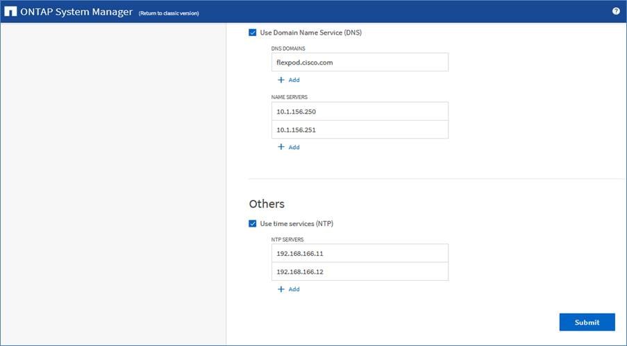
4. Click Submit.
![]() The nodes should be discovered automatically; if they are not, click the Refresh link. By default, the cluster interfaces are created on all the new factory shipping storage controllers.
The nodes should be discovered automatically; if they are not, click the Refresh link. By default, the cluster interfaces are created on all the new factory shipping storage controllers.
![]() If all the nodes are not discovered, then configure the cluster using the command line.
If all the nodes are not discovered, then configure the cluster using the command line.
![]() Cluster license and feature licenses can also be installed after completing cluster creation.
Cluster license and feature licenses can also be installed after completing cluster creation.
The cluster setup is triggered now.
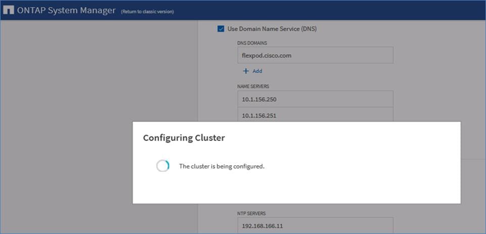
5. Cluster setup complete message will pop up and the page will be redirected to System Manager.
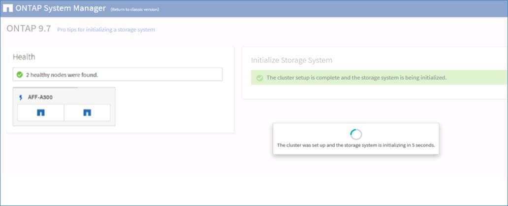
6. Login to System Manager and Under Cluster click Overview to see the Node details.
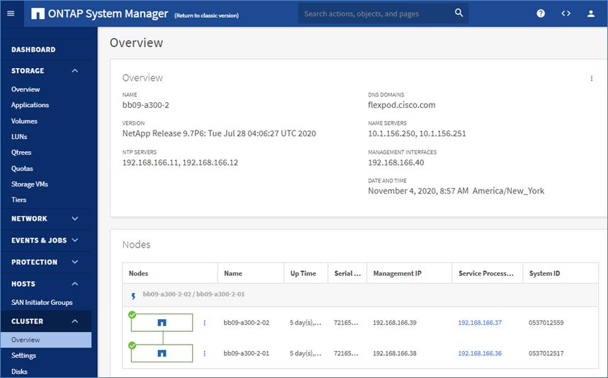
7. To enable and configure AutoSupport, expand Cluster and click on Settings and click More options.
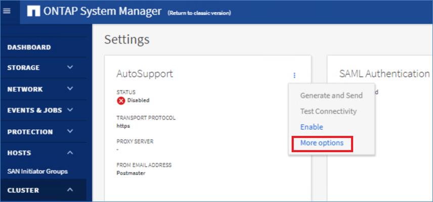
8. Click Edit to change the transport protocol and provide the details.
9. Click Save.
10. In the EMAIL section provide the FROM and RECEPIENTS address and click Save.
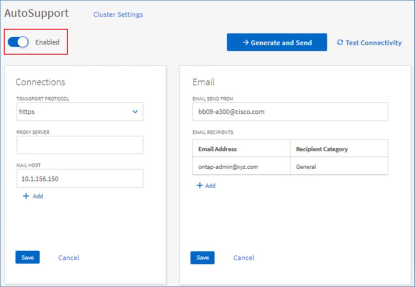
11. Click on Cluster Settings near AutoSupport
12. Click on the right arrow in the License section.
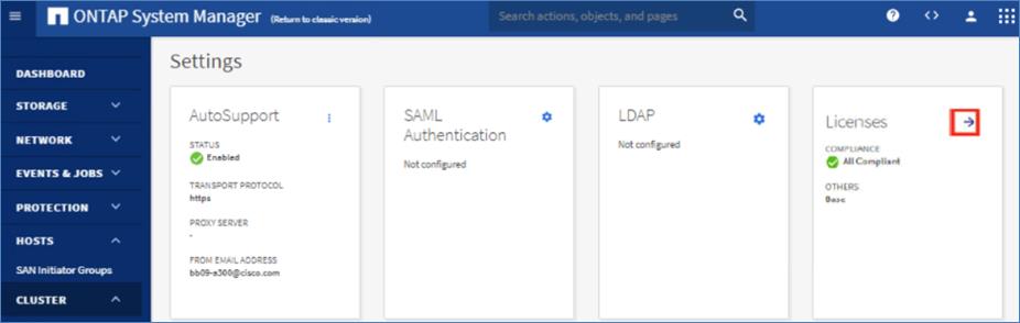
13. Click Add to add the required License to the cluster and enter the license keys in a comma separated list.
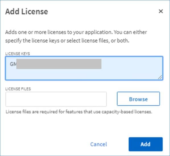
14. Click Storage and then click Tiers to configure the storage aggregates.
15. Click Add Local Tier and allow ONTAP System Manager to recommend a storage aggregate configuration.
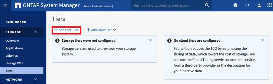
16. Expand the recommendation details and click Save.
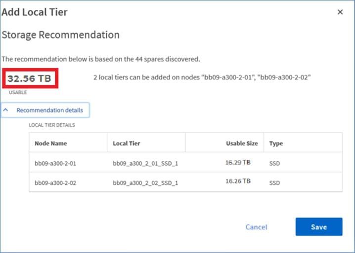
To log into the cluster, follow these steps:
1. Open an SSH connection to either the cluster IP or the host name.
2. Log in to the admin user with the password you provided earlier.
To confirm that storage failover is enabled, run the following commands for a failover pair:
1. Verify the status of the storage failover.
storage failover show
![]() Both <st-node01> and <st-node02> must be capable of performing a takeover. Continue with step 2 if the nodes are capable of performing a takeover.
Both <st-node01> and <st-node02> must be capable of performing a takeover. Continue with step 2 if the nodes are capable of performing a takeover.
2. Enable failover on one of the two nodes if it was not completed during the installation.
storage failover modify -node <st-node01> -enabled true
![]() Enabling failover on one node enables it for both nodes.
Enabling failover on one node enables it for both nodes.
3. Verify the HA status for a two-node cluster.
![]() This step is not applicable for clusters with more than two nodes.
This step is not applicable for clusters with more than two nodes.
cluster ha show
4. Continue with step 5 if high availability is not configured.
5. Only enable HA mode for two-node clusters. Do not run this command for clusters with more than two nodes because it causes problems with failover.
cluster ha modify -configured true
Do you want to continue? {y|n}: y
6. Verify that hardware assist is correctly configured.
Set Auto-Revert on Cluster Management
To set the auto-revert parameter on the cluster management interface, follow this step:
![]() A storage virtual machine (SVM) is referred to as a Vserver or vserver in the GUI and CLI.
A storage virtual machine (SVM) is referred to as a Vserver or vserver in the GUI and CLI.
Run the following command:
Zero All Spare Disks
To zero all spare disks in the cluster, run the following command:
disk zerospares
![]() Advanced Data Partitioning creates a root partition and two data partitions on each SSD drive in an AFF configuration. Disk autoassign should have assigned one data partition to each node in an HA pair. If a different disk assignment is required, disk autoassignment must be disabled on both nodes in the HA pair by running the disk option modify command. Spare partitions can then be moved from one node to another by running the disk removeowner and disk assign commands.
Advanced Data Partitioning creates a root partition and two data partitions on each SSD drive in an AFF configuration. Disk autoassign should have assigned one data partition to each node in an HA pair. If a different disk assignment is required, disk autoassignment must be disabled on both nodes in the HA pair by running the disk option modify command. Spare partitions can then be moved from one node to another by running the disk removeowner and disk assign commands.
Set Up Service Processor Network Interface
To assign a static IPv4 address to the service processor on each node, run the following commands:
system service-processor network modify –node <st-node01> -address-family IPv4 –enable true –dhcp none –ip-address <node01-sp-ip> -netmask <node01-sp-mask> -gateway <node01-sp-gateway>
system service-processor network modify –node <st-node02> -address-family IPv4 –enable true –dhcp none –ip-address <node02-sp-ip> -netmask <node02-sp-mask> -gateway <node02-sp-gateway>
![]() The service processor IP addresses should be in the same subnet as the node management IP addresses.
The service processor IP addresses should be in the same subnet as the node management IP addresses.
Create Auto-provisioned Aggregates
It is a best practice to allow ONTAP to create auto provisioned aggregates. The auto provisioning tool will create a storage layout including the appropriate number of spare disks according to ONTAP best practices. To create new storage aggregates with the auto provisioning tool, run the following commands, or skip to the manual aggregate creation steps below.
bb09-a300-2::*> storage aggregate auto-provision -verbose
Per node summary of new aggregates to create, discovered spares, and also
remaining spare disks and partitions after aggregate creation:
New Total New -Discovered Spare- -Remaining Spare-
Node Aggrs Usable Size Disks Partitions Disks Partitions
------------------ ----- ------------ ------ ----------- ------ ----------
bb09-a300-2-01 1 16.29TB 0 24 0 1
bb09-a300-2-02 1 16.26TB 0 24 0 1
------------------ ----- ------------ ------ ----------- ------ ----------
Total: 2 32.56TB 0 48 0 2
New data aggregates to create with counts of
disks and partitions to be used:
-Devices To Use-
Node New Data Aggregate Usable Size Disks Partitions
------------------ ---------------------------- ------------ ----- ----------
bb09-a300-2-01 bb09_a300_2_01_SSD_1 16.29TB 0 23
bb09-a300-2-02 bb09_a300_2_02_SSD_1 16.26TB 0 23
RAID group layout showing how spare disks and partitions will be used
in new data aggregates to be created:
RAID Group In New Disk Usable Disk Or ---Count---
Data Aggregate To Be Created Type Size Partition Data Parity
-------------------------------------- ------ ---------- --------- ---- ------
/bb09_a300_2_01_SSD_1/plex0/rg0 SSD 894.3GB partition 21 2
/bb09_a300_2_02_SSD_1/plex0/rg1 SSD 894.3GB partition 21 2
Details about spare disks and partitions remaining after aggregate creation:
Disk Device Disk Or Remaining
Node Type Usable Size Partition Spares
------------------ ------ ------------ --------- ---------
bb09-a300-2-01 SSD 894.3GB partition 1
bb09-a300-2-02 SSD 894.3GB partition 1
Do you want to create recommended aggregates? {y|n}: y
Info: Aggregate auto provision has started. Use the "storage aggregate
show-auto-provision-progress" command to track the progress.
Create Aggregates Manually (Optional)
An aggregate containing the root volume is created during the ONTAP setup process. To create additional aggregates, determine the aggregate name, the node on which to create it, and the number of disks it should contain.
To create new aggregates, run the following commands:
storage aggregate create -aggregate aggr1_node01 -node <st-node01> -diskcount <num-disks>
storage aggregate create -aggregate aggr1_node02 -node <st-node02> -diskcount <num-disks>
![]() You should have the minimum number of hot spare disks for hot spare disk partitions recommended for your aggregate.
You should have the minimum number of hot spare disks for hot spare disk partitions recommended for your aggregate.
![]() For all-flash aggregates, you should have a minimum of one hot spare disk or disk partition. For non-flash homogenous aggregates, you should have a minimum of two hot spare disks or disk partitions. For Flash Pool aggregates, you should have a minimum of two hot spare disks or disk partitions for each disk type.
For all-flash aggregates, you should have a minimum of one hot spare disk or disk partition. For non-flash homogenous aggregates, you should have a minimum of two hot spare disks or disk partitions. For Flash Pool aggregates, you should have a minimum of two hot spare disks or disk partitions for each disk type.
![]() Start with five disks initially; you can add disks to an aggregate when additional storage is required. In an AFF configuration with a small number of SSDs, you might want to create an aggregate with all but one remaining disk (spare) assigned to the controller.
Start with five disks initially; you can add disks to an aggregate when additional storage is required. In an AFF configuration with a small number of SSDs, you might want to create an aggregate with all but one remaining disk (spare) assigned to the controller.
![]() The aggregate cannot be created until disk zeroing completes. Run the storage aggregate show command to display the aggregate creation status. Do not proceed until both aggr1_node1 and aggr1_node2 are online.
The aggregate cannot be created until disk zeroing completes. Run the storage aggregate show command to display the aggregate creation status. Do not proceed until both aggr1_node1 and aggr1_node2 are online.
Remove Ports from Default Broadcast Domain
By default, all network ports are included in the default broadcast domain. Network ports used for data services (for example, e2a, e2e, and so on) should be removed from the default broadcast domain, leaving just the management network port (e0M). To perform this task, run the following commands:
net port broadcast-domain remove-ports -broadcast-domain Default -ports <st-node01>:e2a,<st-node01>:e2b,<st-node02>:e2a,<st-node02>:e2b
network port broadcast-domain show
Disable Flow Control on 10GbE and 40GbE Ports
NetApp recommends disabling flow control on all the 10/40/100GbE and UTA2 ports that are connected to external devices. To disable flow control, follow these steps:
1. Run the following commands to configure node 01:
network port modify -node <st-node01> -port e2a,e2e -flowcontrol-admin none
Warning: Changing the network port settings will cause a several second interruption in carrier.
Do you want to continue? {y|n}: y
2. Run the following commands to configure node 02:
network port modify -node <st-node02> -port e2a,e2e -flowcontrol-admin none
Warning: Changing the network port settings will cause a several second interruption in carrier.
Do you want to continue? {y|n}: y
Enable Cisco Discovery Protocol
To enable the Cisco Discovery Protocol (CDP) on the NetApp storage controllers, run the following command to enable CDP on ONTAP:
node run -node * options cdpd.enable on
![]() To be effective, CDP must also be enabled on directly connected networking equipment such as switches and routers.
To be effective, CDP must also be enabled on directly connected networking equipment such as switches and routers.
Enable Link-layer Discovery Protocol on all Ethernet Ports
Enable the exchange of Link-layer Discovery Protocol (LLDP) neighbor information between the storage and network switches with the following step:
1. Enable LLDP on all ports of all nodes in the cluster.
node run * options lldp.enable on
Create Management Broadcast Domain
If the management interfaces are required to be on a separate VLAN, create a new broadcast domain for those interfaces by running the following command:
network port broadcast-domain create -broadcast-domain IB-MGMT -mtu 1500
network port broadcast-domain show
To create an NFS data broadcast domain with an MTU of 9000, run the following commands to create a broadcast domain for NFS in ONTAP:
network port broadcast-domain create -broadcast-domain Infra_NFS -mtu 9000
network port broadcast-domain show
To create an iSCSI data broadcast domain with an MTU of 9000, run the following commands to create a broadcast domain for iSCSI in ONTAP:
network port broadcast-domain create -broadcast-domain Infra-iSCSI-A -mtu 9000
network port broadcast-domain create -broadcast-domain Infra-iSCSI-B -mtu 9000
Create Interface Groups
To create the LACP interface groups for the 40GbE data interfaces, run the following commands:
network port ifgrp create -node <st-node01> -ifgrp a0a -distr-func port -mode multimode_lacp
network port ifgrp add-port -node <st-node01> -ifgrp a0a -port e2a
network port ifgrp add-port -node <st-node01> -ifgrp a0a -port e2e
network port ifgrp create -node <st-node02> -ifgrp a0a -distr-func port -mode multimode_lacp
network port ifgrp add-port -node <st-node02> -ifgrp a0a -port e2a
network port ifgrp add-port -node <st-node02> -ifgrp a0a -port e2e
network port ifgrp show
To create VLANs, follow these steps:
1. Create the management VLAN ports and add them to the management broadcast domain.
network port vlan create –node <st-node01> -vlan-name a0a-<ib-mgmt-vlan-id>
network port vlan create –node <st-node02> -vlan-name a0a-<ib-mgmt-vlan-id>
network port broadcast-domain add-ports -broadcast-domain IB-MGMGT -ports <st-node01>:a0a-<ib-mgmt-vlan-id>,<st-node02>:a0a-<ib-mgmt-vlan-id>
network port vlan show
2. Create the NFS VLAN ports and add them to the Infra_NFS broadcast domain.
network port vlan create –node <st-node01> -vlan-name a0a-<infra-nfs-vlan-id>
network port vlan create –node <st-node02> -vlan-name a0a-<infra-nfs-vlan-id>
network port broadcast-domain add-ports -broadcast-domain Infra_NFS -ports <st-node01>:a0a-<infra-nfs-vlan-id>,<st-node02>:a0a-<infra-nfs-vlan-id>
3. Create the iSCSI VLAN ports for the iSCSI LIFs on each storage controller
network port vlan create –node <st-node01> -vlan-name a0a-<infra-iscsi-a-vlan-id>
network port vlan create –node <st-node02> -vlan-name a0a-<infra-iscsi-a-vlan-id>
network port vlan create –node <st-node01> -vlan-name a0a-<infra-iscsi-b-vlan-id>
network port vlan create –node <st-node02> -vlan-name a0a-<infra-iscsi-b-vlan-id>
4. To add each of the iSCSI VLAN ports to the corresponding broadcast domain, run the following commands:
network port broadcast-domain add-ports -broadcast-domain Infra-iSCSI-A -ports <st-node01>:a0a-<infra-iscsi-a-vlan-id>
network port broadcast-domain add-ports -broadcast-domain Infra-iSCSI-B -ports <st-node01>:a0a-<infra-iscsi-b-vlan-id>
network port broadcast-domain add-ports -broadcast-domain Infra-iSCSI-A -ports <st-node02>:a0a-<infra-iscsi-a-vlan-id>
network port broadcast-domain add-ports -broadcast-domain Infra-iSCSI-B -ports <st-node02>:a0a-<infra-iscsi-b-vlan-id>
network port broadcast-domain show
Configure Network Time Protocol
To configure time synchronization on the cluster, follow these steps:
1. Set the time zone for the cluster.
timezone <timezone>
![]() For example, in the eastern United States, the time zone is America/New_York.
For example, in the eastern United States, the time zone is America/New_York.
2. Set the date for the cluster.
date <ccyymmddhhmm.ss>
![]() The format for the date is <[Century][Year][Month][Day][Hour][Minute].[Second]> (for example, 202009271549.30).
The format for the date is <[Century][Year][Month][Day][Hour][Minute].[Second]> (for example, 202009271549.30).
3. Configure the Network Time Protocol (NTP) servers for the cluster.
cluster time-service ntp server create -server <nexus-A-mgmt0-ip>
cluster time-service ntp server create -server <nexus-B-mgmt0-ip>
Configure Simple Network Management Protocol
To configure the Simple Network Management Protocol (SNMP), follow these steps:
1. Configure basic SNMP information, such as the location and contact. When polled, this information is visible as the sysLocation and sysContact variables in SNMP.
snmp contact <snmp-contact>
snmp location “<snmp-location>”
snmp init 1
options snmp.enable on
2. Configure SNMP traps to send to remote hosts, such as a DFM server or another fault management system.
snmp traphost add <oncommand-um-server-fqdn>
SNMPv3 offers advanced security by using encryption and passphrases. The SNMPv3 user can run SNMP utilities from the traphost using the authentication and privacy settings that you specify. To configure SNMPv3 access, run the following commands:
security login create -user-or-group-name <<snmp-v3-usr>> -application snmp -authentication-method usm
Enter the authoritative entity's EngineID [local EngineID]:
Which authentication protocol do you want to choose (none, md5, sha, sha2-256) [none]: <<snmp-v3-auth-proto>>
Enter the authentication protocol password (minimum 8 characters long):
Enter the authentication protocol password again:
Which privacy protocol do you want to hoose (none, des, aes128) [none]: <<snmpv3-priv-proto>>
Enter privacy protocol password (minimum 8 characters long):
Enter privacy protocol password again:
![]() For additional detail refer to the SNMP Configuration Express Guide
For additional detail refer to the SNMP Configuration Express Guide
Create SVM
To create an infrastructure SVM, follow these steps:
1. Run the vserver create command.
vserver create –vserver Infra-SVM –rootvolume infra_svm_root –aggregate aggr1_node01 –rootvolume-security-style unix
2. Remove the unused data protocols from the SVM: CIFS, iSCSI, and NVMe.
vserver remove-protocols –vserver Infra-SVM -protocols cifs
3. Add the two data aggregates to the Infra-SVM aggregate list for the NetApp VSC.
vserver modify –vserver Infra-SVM –aggr-list aggr1_node01,aggr1_node02
4. Enable and run the NFS protocol in the Infra-SVM.
vserver nfs create -vserver Infra-SVM -udp disabled
![]() If the NFS license was not installed during the cluster configuration, make sure to install the license before starting the NFS service.
If the NFS license was not installed during the cluster configuration, make sure to install the license before starting the NFS service.
5. Turn on the SVM vstorage parameter for the NetApp NFS VAAI plug-in.
vserver nfs modify –vserver Infra-SVM –vstorage enabled
vserver nfs show -fields vstorage
Create Load-Sharing Mirrors of SVM Root Volume
To create a load-sharing mirror of an SVM root volume, follow these steps:
1. Create a volume to be the load-sharing mirror of the infrastructure SVM root volume on each node.
volume create –vserver Infra-SVM –volume infra_svm_root_m01 –aggregate aggr1_node01 –size 1GB –type DP
volume create –vserver Infra-SVM –volume infra_svm_root_m02 –aggregate aggr1_node02 –size 1GB –type DP
2. Create a job schedule to update the root volume mirror relationships every 15 minutes.
job schedule interval create -name 15min -minutes 15
3. Create the mirroring relationships.
snapmirror create –source-path Infra-SVM:infra_svm_root -destination-path Infra-SVM:infra_svm_root_m01 –type LS -schedule 15min
snapmirror create –source-path Infra-SVM:infra_svm_root –destination-path Infra-SVM:infra_svm_root_m02 –type LS -schedule 15min
4. Initialize the mirroring relationship.
snapmirror initialize-ls-set –source-path Infra-SVM:infra_svm_root
snapmirror show -type ls
Create Block Protocol (iSCSI) Service
Run the following command to create the iSCSI service on each SVM. This command also starts the iSCSI service and sets the iSCSI Qualified Name (IQN) for the SVM.
iscsi create -vserver Infra-SVM
iscsi show
Configure HTTPS Access
To configure secure access to the storage controller, follow these steps:
1. Increase the privilege level to access the certificate commands.
set -privilege diag
Do you want to continue? {y|n}: y
2. Generally, a self-signed certificate is already in place. Verify the certificate and obtain parameters (for example, the <serial-number>) by running the following command:
security certificate show
3. For each SVM shown, the certificate common name should match the DNS FQDN of the SVM. Delete the two default certificates and replace them with either self-signed certificates or certificates from a certificate authority (CA). To delete the default certificates, run the following commands:
security certificate delete -vserver Infra-SVM -common-name Infra-SVM -ca Infra-SVM -type server -serial <serial-number>
![]() Deleting expired certificates before creating new certificates is a best practice. Run the security certificate delete command to delete the expired certificates. In the following command, use TAB completion to select and delete each default certificate.
Deleting expired certificates before creating new certificates is a best practice. Run the security certificate delete command to delete the expired certificates. In the following command, use TAB completion to select and delete each default certificate.
4. To generate and install self-signed certificates, run the following commands as one-time commands. Generate a server certificate for the Infra-SVM and the cluster SVM. Use TAB completion to aid in the completion of these commands.
security certificate create -common-name <cert-common-name> -type server -size 2048 -country <cert-country> -state <cert-state> -locality <cert-locality> -organization <cert-org> -unit <cert-unit> -email-addr <cert-email> -expire-days <cert-days> -protocol SSL -hash-function SHA256 -vserver Infra-SVM
5. To obtain the values for the parameters required in step 5 (<cert-ca> and <cert-serial>), run the
security certificate show
6. Enable each certificate that was just created by using the –server-enabled true and –client-enabled false parameters. Use TAB completion to aid in the completion of these commands.
security ssl modify -vserver <clustername> -server-enabled true -client-enabled false -ca <cert-ca> -serial <cert-serial> -common-name <cert-common-name>
7. Disable HTTP cluster management access.
system services firewall policy delete -policy mgmt -service http –vserver <clustername>
![]() It is normal for some of these commands to return an error message stating that the entry does not exist.
It is normal for some of these commands to return an error message stating that the entry does not exist.
8. Change back to the normal admin privilege level and verify that the system logs are available in a web browser.
set –privilege admin
https://<node01-mgmt-ip>/spi
https://<node02-mgmt-ip>/spi
To configure NFSv3 on the SVM, follow these steps:
1. Create a new rule for the infrastructure NFS subnet in the default export policy.
vserver export-policy rule create –vserver Infra-SVM -policyname default –ruleindex 1 –protocol nfs -clientmatch <infra-nfs-subnet-cidr> -rorule sys –rwrule sys -superuser sys –allow-suid true
2. Assign the FlexPod export policy to the infrastructure SVM root volume.
volume modify –vserver Infra-SVM –volume infra_svm_root –policy default
The following information is required to create a NetApp FlexVol® volume:
● The volume name
● The volume size
● The aggregate on which the volume exists
To create a FlexVol volume, run the following commands:
volume create -vserver Infra-SVM -volume infra_datastore_1 -aggregate aggr1_node01 -size 1TB -state online -policy default -junction-path /infra_datastore_1 -space-guarantee none -percent-snapshot-space 0
volume create -vserver Infra-SVM -volume infra_datastore_2 -aggregate aggr1_node02 -size 1TB -state online -policy default -junction-path /infra_datastore_2 -space-guarantee none -percent-snapshot-space 0
volume create -vserver Infra-SVM -volume infra_swap -aggregate aggr1_node01 -size 100GB -state online -policy default -junction-path /infra_swap -space-guarantee none -percent-snapshot-space 0 -snapshot-policy none
volume create -vserver Infra-SVM -volume esxi_boot -aggregate aggr1_node01 -size 200GB -state online -policy default -space-guarantee none -percent-snapshot-space 0
snapmirror update-ls-set -source-path Infra-SVM:infra_svm_root
![]() If SnapCenter will be used to back up the infra datastores volume, add “-snapshot-policy none” to the end of the volume create command for the infra datastores volume.
If SnapCenter will be used to back up the infra datastores volume, add “-snapshot-policy none” to the end of the volume create command for the infra datastores volume.
Create Boot LUNs
To create boot LUNs, run the following commands:
lun create -vserver Infra-SVM -path /vol/esxi_boot/VM-Host-Infra-01 -size 32GB -ostype vmware -space-reserve disabled
lun create -vserver Infra-SVM -path /vol/esxi_boot/VM-Host-Infra-02 -size 32GB -ostype vmware -space-reserve disabled
lun create -vserver Infra-SVM -path /vol/esxi_boot/VM-Host-Infra-03 -size 32GB -ostype vmware -space-reserve disabled
lun create -vserver Infra-SVM -path /vol/esxi_boot/VM-Host-Infra-04 -size 32GB -ostype vmware -space-reserve disabled
lun create -vserver Infra-SVM -path /vol/esxi_boot/VM-Host-Infra-05 -size 32GB -ostype vmware -space-reserve disabled
On NetApp All Flash FAS systems, deduplication is enabled by default. To disable the efficiency policy on the infra_swap volume, run the following command:
To create NFS LIFs, run the following commands:
network interface create -vserver Infra-SVM -lif nfs-lif01 -role data -data-protocol nfs -home-node <st-node01> -home-port a0a-<infra-nfs-vlan-id> –address <node01-nfs_lif01-ip> -netmask <node01-nfs_lif01-mask> -status-admin up –failover-policy broadcast-domain-wide –firewall-policy data –auto-revert true
network interface create -vserver Infra-SVM -lif nfs-lif02 -role data -data-protocol nfs -home-node <st-node02> -home-port a0a-<infra-nfs-vlan-id> –address <node02-nfs_lif02-ip> -netmask <node02-nfs_lif02-mask>> -status-admin up –failover-policy broadcast-domain-wide –firewall-policy data –auto-revert true
network interface show
Run the following commands to create four iSCSI LIFs (two on each node):
network interface create -vserver Infra-SVM -lif iscsi-lif-1a -role data -data-protocol iscsi -home-node <st-node01> -home-port a0a-<infra-iscsi-a-vlan-id> -address <st-node01-infra-iscsi-a–ip> -netmask <infra-iscsi-a-mask> -status-admin up
network interface create -vserver Infra-SVM -lif iscsi-lif-1b -role data -data-protocol iscsi -home-node <st-node01> -home-port a0a-<infra-iscsi-b-vlan-id> -address <st-node01-infra-iscsi-b–ip> -netmask <infra-iscsi-b-mask> –status-admin up
network interface create -vserver Infra-SVM -lif iscsi-lif-2a -role data -data-protocol iscsi -home-node <st-node02> -home-port a0a-<infra-iscsi-a-vlan-id> -address <st-node02-infra-iscsi-a–ip> -netmask <infra-iscsi-a-mask> –status-admin up
network interface create -vserver Infra-SVM -lif iscsi-lif-2b -role data -data-protocol iscsi -home-node <st-node02> -home-port a0a-<infra-iscsi-b-vlan-id> -address <st-node02-infra-iscsi-b–ip> -netmask <infra-iscsi-b-mask> –status-admin up
network interface show
Add Infrastructure SVM Administrator
To add the infrastructure SVM administrator and SVM administration LIF in the in-band management network, follow these steps:
1. Run the following commands:
network interface create –vserver Infra-SVM –lif svm-mgmt –role data –data-protocol none –home-node <st-node02> -home-port a0a-<ib-mgmt-vlan-id> –address <svm-mgmt-ip> -netmask <svm-mgmt-mask> -status-admin up –failover-policy broadcast-domain-wide –firewall-policy mgmt –auto-revert true
2. Create a default route that enables the SVM management interface to reach the outside world.
network route create –vserver Infra-SVM -destination 0.0.0.0/0 –gateway <svm-mgmt-gateway>
network route show
3. Set a password for the SVM vsadmin user and unlock the user.
security login password –username vsadmin –vserver Infra-SVM
Enter a new password: <password>
Enter it again: <password>
security login unlock –username vsadmin –vserver Infra-SVM
![]() A cluster serves data through at least one and possibly several SVMs. We have just gone through creating a single SVM. If you would like to configure your environment with multiple SVMs, this is a good time to create them.
A cluster serves data through at least one and possibly several SVMs. We have just gone through creating a single SVM. If you would like to configure your environment with multiple SVMs, this is a good time to create them.
Configure and Test AutoSupport
NetApp AutoSupport® sends support summary information to NetApp through HTTPS. To configure AutoSupport, run the following command:
system node autosupport modify -node * -state enable –mail-hosts <mailhost> -transport https -support enable -noteto <storage-admin-email>
Test the AutoSupport configuration by sending a message from all nodes of the cluster:
autosupport invoke -node * -type all -message “FlexPod storage configuration completed”
Cisco UCS Base Configuration
This FlexPod deployment explains the configuration steps for the Cisco UCS 6454 Fabric Interconnects (FI) in a design that will support iSCSI boot.
Perform Initial Setup of Cisco UCS 6454 Fabric Interconnects for FlexPod Environments
This section provides the detailed procedures for configuring the Cisco Unified Computing System (Cisco UCS) for use in a FlexPod environment. The steps are necessary to provision the Cisco UCS B-Series and C-Series servers and should be followed precisely to avoid improper configuration.
Cisco UCS Fabric Interconnect A
To configure the Cisco UCS for use in a FlexPod environment, follow these steps:
1. Connect to the console port on the first Cisco UCS fabric interconnect.
Enter the configuration method. (console/gui) ? console
Enter the management mode. (ucsm/intersight)? ucsm
Enter the setup mode; setup newly or restore from backup. (setup/restore) ? setup
You have chosen to setup a new Fabric interconnect. Continue? (y/n): y
Enforce strong password? (y/n) [y]: Enter
Enter the password for "admin": <password>
Confirm the password for "admin": <password>
Is this Fabric interconnect part of a cluster(select 'no' for standalone)? (yes/no) [n]: y
Enter the switch fabric (A/B) []: A
Enter the system name: <ucs-cluster-name>
Physical Switch Mgmt0 IP address : <ucsa-mgmt-ip>
Physical Switch Mgmt0 IPv4 netmask : <ucsa-mgmt-mask>
IPv4 address of the default gateway : <ucsa-mgmt-gateway>
Cluster IPv4 address : <ucs-cluster-ip>
Configure the DNS Server IP address? (yes/no) [n]: y
DNS IP address : <dns-server-1-ip>
Configure the default domain name? (yes/no) [n]: y
Default domain name : <ad-dns-domain-name>
Join centralized management environment (UCS Central)? (yes/no) [n]: Enter
Apply and save the configuration (select 'no' if you want to re-enter)? (yes/no): yes
2. Wait for the login prompt for UCS Fabric Interconnect A before proceeding to the next section.
Cisco UCS Fabric Interconnect B
To configure the Cisco UCS for use in a FlexPod environment, follow these steps:
1. Connect to the console port on the second Cisco UCS fabric interconnect.
Enter the configuration method. (console/gui) ? console
Installer has detected the presence of a peer Fabric interconnect. This Fabric interconnect will be added to the cluster. Continue (y/n) ? y
Enter the admin password of the peer Fabric interconnect: <password>
Connecting to peer Fabric interconnect... done
Retrieving config from peer Fabric interconnect... done
Peer Fabric interconnect Mgmt0 IPv4 Address: <ucsa-mgmt-ip>
Peer Fabric interconnect Mgmt0 IPv4 Netmask: <ucsa-mgmt-mask>
Cluster IPv4 address : <ucs-cluster-ip>
Peer FI is IPv4 Cluster enabled. Please Provide Local Fabric Interconnect Mgmt0 IPv4 Address
Physical Switch Mgmt0 IP address : <ucsb-mgmt-ip>
Local fabric interconnect model(UCS-FI-6454)
Peer fabric interconnect is compatible with the local fabric interconnect. Continuing with the installer...
Apply and save the configuration (select 'no' if you want to re-enter)? (yes/no): yes
2. Wait for the login prompt for UCS Fabric Interconnect B before proceeding to the next section.
Cisco UCS Setup
To log into the Cisco Unified Computing System (Cisco UCS) environment, follow these steps:
1. Open a web browser and navigate to the Cisco UCS fabric interconnect cluster address.
![]() You may need to wait at least 5 minutes after configuring the second fabric interconnect for Cisco UCS Manager to open.
You may need to wait at least 5 minutes after configuring the second fabric interconnect for Cisco UCS Manager to open.
2. Click the Launch UCS Manager link to launch Cisco UCS Manager.
3. If prompted to accept security certificates, accept as necessary.
4. When prompted, enter admin as the user name and enter the administrative password.
5. Click Login to log into Cisco UCS Manager.
To enable anonymous reporting, follow this step:
1. In the Anonymous Reporting window, choose whether to send anonymous data to Cisco for improving future products. If you choose Yes, enter the IP address of your SMTP Server. Click OK.
Upgrade Cisco UCS Manager Software to Version 4.1(2a)
This document assumes the use of Cisco UCS 4.1(2a). To upgrade the Cisco UCS Manager software and the Cisco UCS Fabric Interconnect software to version 4.1(2a), refer to Cisco UCS Manager Install and Upgrade Guides.
Cisco Intersight can also be used to upgrade the Cisco UCS Infrastructure (Cisco UCS Manager, Cisco UCS Fabric Interconnects, and Cisco UCS Fabric Extenders) to version 4.1(2a). Before the upgrade can be done from Cisco Intersight, the UCS cluster will need to be claimed into Intersight. Please see the Cisco Intersight section in the FlexPod Management Tools section of this document. For the Cisco Intersight-based upgrade procedure, please see https://intersight.com/help/features#firmware_upgrade. This upgrade does require interacting with Cisco UCS Manager to reboot the Primary Fabric Interconnect when upgrading. Because the Cisco UCS servers are not yet connected to the Cisco UCS Infrastructure, the servers will not be upgraded using Cisco Intersight. However, the Cisco UCS B and C-Series 4.1(2a) bundles need to be manually downloaded to the Cisco UCS system.
It is highly recommended by Cisco to configure Call Home in Cisco UCS Manager. Configuring Call Home will accelerate resolution of support cases. To configure Call Home, follow these steps:
1. In Cisco UCS Manager, click Admin.
2. Choose All > Communication Management > Call Home.
3. Change the State to On.
4. Fill in all the fields according to your Management preferences and click Save Changes and OK to complete configuring Call Home.
To synchronize the Cisco UCS environment to the NTP servers in the Cisco Nexus switches, follow these steps:
1. In Cisco UCS Manager, click Admin.
2. Expand All > Time Zone Management.
3. Choose Timezone.
4. In the Properties pane, choose the appropriate time zone in the Timezone menu.
5. Click Save Changes and then click OK.
6. Click Add NTP Server.
7. Enter <ntp-server> and click OK. Click OK on the confirmation.
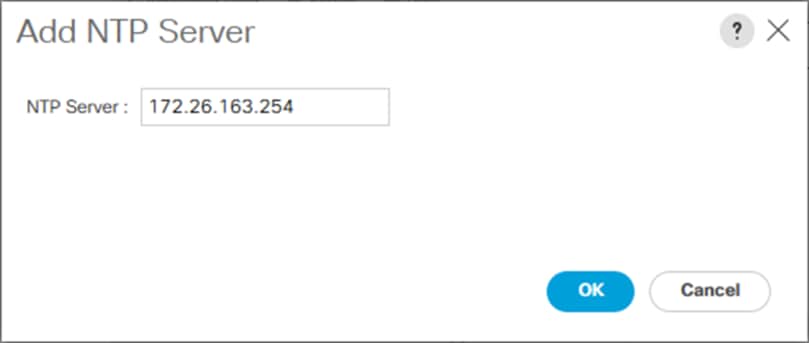
8. Click OK to close the window.
To add one or more additional DNS servers to the UCS environment, follow these steps:
1. In Cisco UCS Manager, click Admin.
2. Expand All > Communications Management.
3. Choose DNS Management.
4. In the Properties pane, choose Specify DNS Server.
5. Enter the IP address of the additional DNS server.

6. Click OK and then click OK again. Repeat this process for any additional DNS servers.
Add an Additional Administrative User
To add an additional locally authenticated Administrative user (flexadmin) to the Cisco UCS environment in case issues arise with the admin user, follow these steps:
1. In Cisco UCS Manager, click Admin.
2. Expand User Management > User Services > Locally Authenticated Users.
3. Right-click Locally Authenticated Users and choose Create User.
4. In the Create User fields it is only necessary to fill in the Login ID, Password, and Confirm Password fields. Fill in the Create User fields according to your local security policy.
5. Leave the Account Status field set to Active.
6. Set Account Expires according to your local security policy.
7. Under Roles, choose admin.
8. Leave Password Required selected for the SSH Type field.
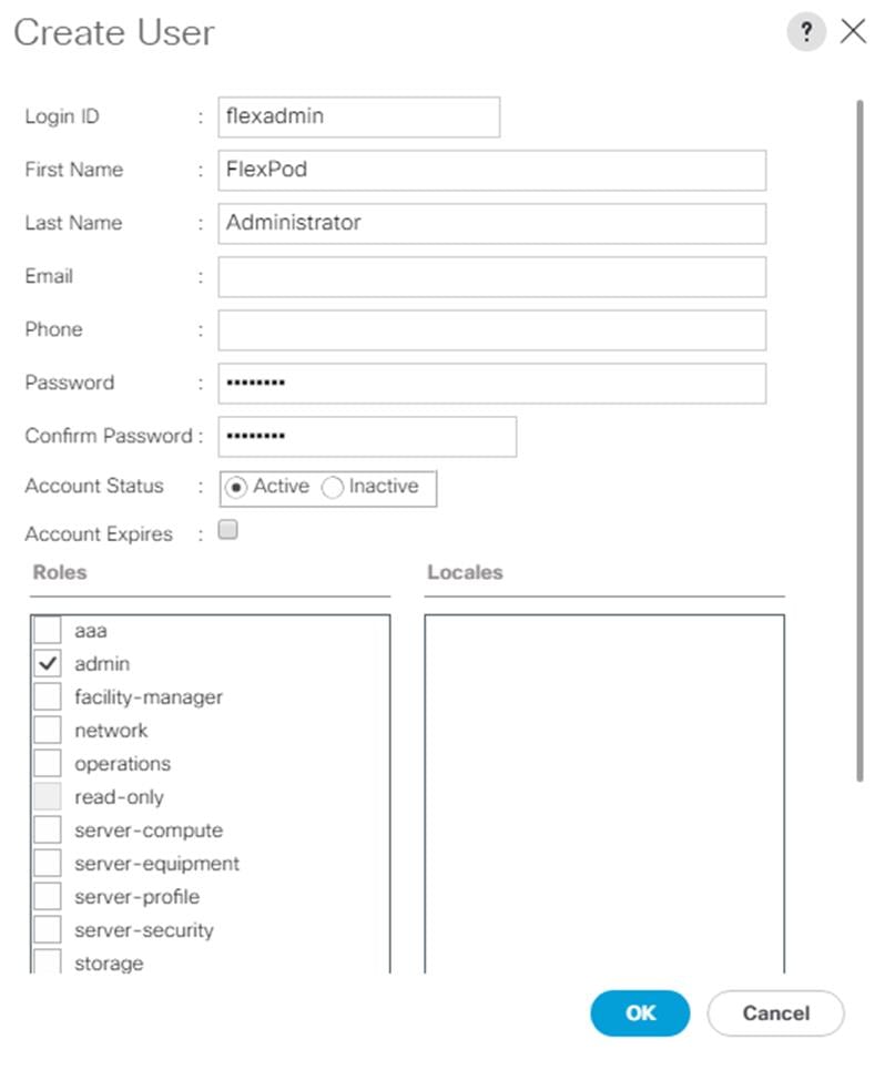
9. Click OK and then click OK again to complete adding the user.
Setting the discovery policy simplifies the addition of Cisco UCS B-Series chassis and of additional fabric extenders for further Cisco UCS C-Series connectivity. Enabling the info policy enables Fabric Interconnect neighbor information to be displayed. To modify these policies, follow these steps:
1. In Cisco UCS Manager, click Equipment and choose the Policies tab, and select the Global Policies sub-tab.
2. Set the Chassis/FEX Discovery Policy to match the minimum number of ports that are cabled between the chassis or fabric extenders (FEXes) and the fabric interconnects.
![]() If varying numbers of links between chassis and the Fabric Interconnects will be used, set Action to 2 Link, the minimum recommended number of links for a FlexPod.
If varying numbers of links between chassis and the Fabric Interconnects will be used, set Action to 2 Link, the minimum recommended number of links for a FlexPod.
![]() On the 6454 Fabric Interconnects, the Link Grouping Preference is automatically set to Port Channel and is greyed out. On a 6300 Series or 6200 Series Fabric Interconnect, set the Link Grouping Preference to Port Channel. If Backplane Speed Preference appears, leave it set at 40G.
On the 6454 Fabric Interconnects, the Link Grouping Preference is automatically set to Port Channel and is greyed out. On a 6300 Series or 6200 Series Fabric Interconnect, set the Link Grouping Preference to Port Channel. If Backplane Speed Preference appears, leave it set at 40G.
3. Scroll down to Info Policy and choose Enabled for Action.
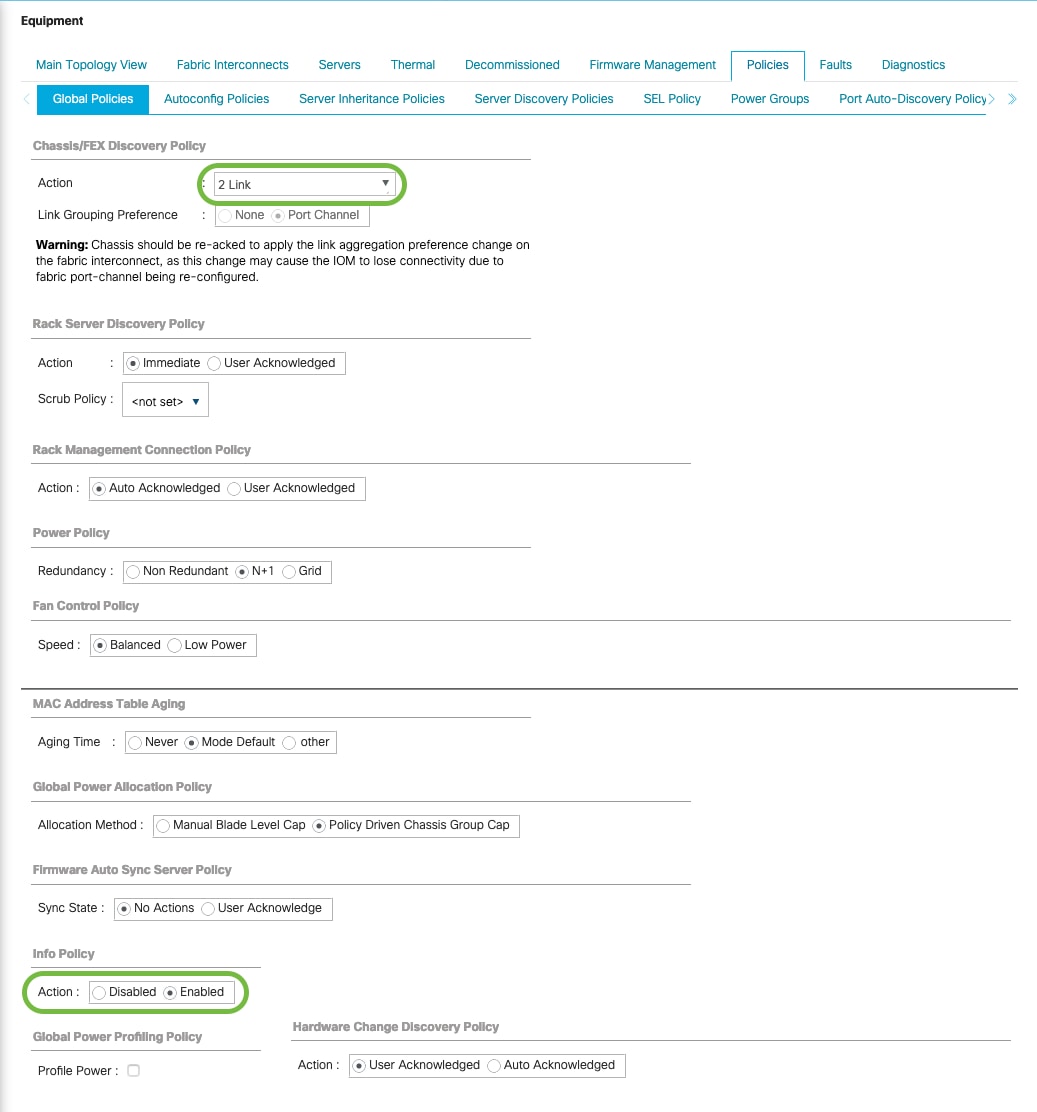
4. Click Save Changes and then click OK.
Enable Port Auto-Discovery Policy
Setting the port auto-discovery policy enables automatic discovery of Cisco UCS B-Series chassis server ports. To modify the port auto-discovery policy, follow these steps:
1. In Cisco UCS Manager, click Equipment, choose All > Equipment in the Navigation Pane, and choose the Policies tab.
2. Under Port Auto-Discovery Policy, set Auto Configure Server Port to Enabled.
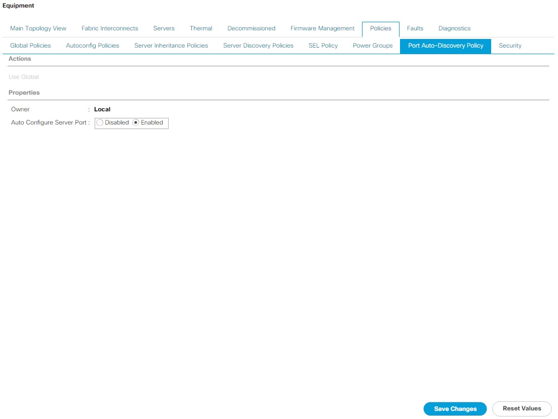
3. Click Save Changes and then click OK.
Enable Server and Uplink Ports
To enable and verify server and uplink ports, follow these steps:
1. In Cisco UCS Manager, click Equipment.
2. Expand Equipment > Fabric Interconnects > Fabric Interconnect A (primary) > Fixed Module.
3. Expand and choose Ethernet Ports.
4. Verify that all ports connected to UCS chassis and rack mounts are configured as Server ports and have a status of Up.
5. If any rack mount ports are missing, choose the ports that are connected to Cisco FEXes and direct connect Cisco UCS C-Series servers, right-click them, and choose Configure as Server Port.
6. Click Yes to confirm server ports and click OK.
7. Verify that the ports connected to the chassis, C-series servers and Cisco FEX are now configured as server ports.
8. Choose the ports that are connected to the Cisco Nexus switches, right-click them, and choose Configure as Uplink Port.
9. Click Yes to confirm uplink ports and click OK.
10. Choose Equipment > Fabric Interconnects > Fabric Interconnect B (subordinate) > Fixed Module.
11. Expand and choose Ethernet Ports.
12. Verify that all ports connected to UCS chassis and rack mounts are configured as Server ports and have a status of Up.
13. If any rack mount ports are missing, choose the ports that are connected to Cisco FEXes and direct connect C-series servers, right-click them, and choose Configure as Server Port.
14. Click Yes to confirm server ports and click OK.
15. Verify that the ports connected to the chassis, C-series servers and Cisco FEX are now configured as server ports.
16. Choose the ports that are connected to the Cisco Nexus switches, right-click them, and choose Configure as Uplink Port.
17. Click Yes to confirm the uplink ports and click OK.
Acknowledge Cisco UCS Chassis and FEX
To acknowledge all Cisco UCS chassis and any external FEX modules, follow these steps:
1. In Cisco UCS Manager, click Equipment.
2. Expand Chassis and choose each chassis that is listed.
3. Right-click each chassis and choose Acknowledge Chassis.
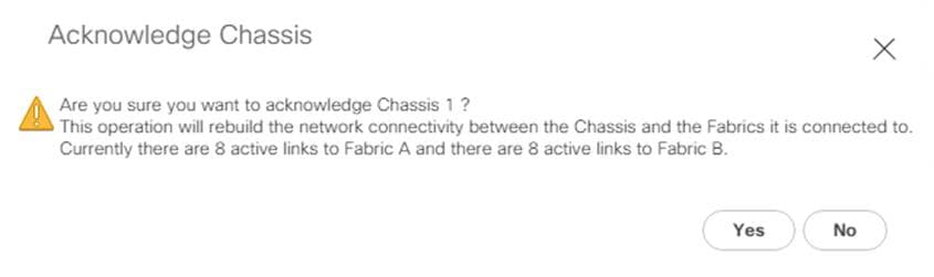
4. Click Yes and then click OK to complete acknowledging the chassis.
5. If Nexus FEXes are part of the configuration, expand Rack Mounts and FEX.
6. Right-click each FEX that is listed and choose Acknowledge FEX.
7. Click Yes and then click OK to complete acknowledging the FEX.
To this point in the UCS deployment, all items have been deployed at the root level in Cisco UCS Manager. To allow this UCS to be shared among different projects, UCS Organizations can be created. In this validation, the organization for this FlexPod deployment is FlexPod. To create an organization for this FlexPod deployment, follow these steps:
1. In Cisco UCS Manager, click Servers.
2. In the Navigation Pane, expand Servers > Service Profiles.
3. Right-click root under Service Profiles and choose Create Organization.
4. Provide a name for the Organization to indicate this FlexPod deployment and optionally provide a Description.
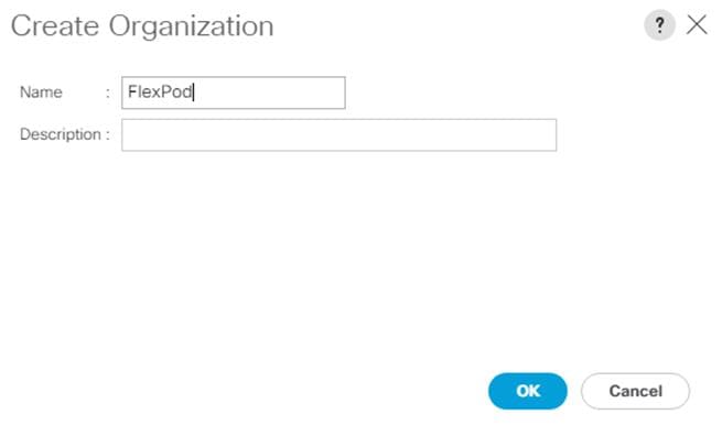
5. Click OK then click OK again to complete creating the organization.
Add Block of IP Addresses for KVM Access
To create a block of IP addresses for in band server Keyboard, Video, Mouse (KVM) access in the Cisco UCS environment, follow these steps:
1. In Cisco UCS Manager, click LAN.
2. Expand Pools > root > IP Pools.
3. Right-click IP Pool ext-mgmt and choose Create Block of IPv4 Addresses.
4. Enter the starting IP address of the block, number of IP addresses required, and the subnet mask and gateway information. Optionally, enter the Primary and Secondary DNS server addresses.
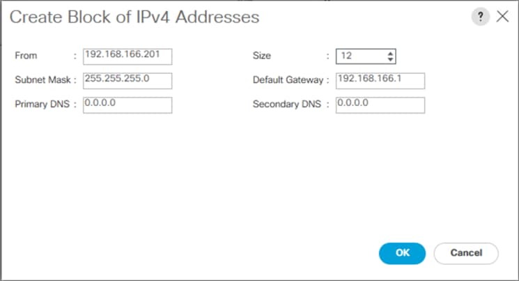
5. Click OK to create the block.
6. Click OK in the confirmation message.
Create IP Pools for iSCSI Boot
To configure the necessary IP pools for iSCSI boot for the Cisco UCS environment, follow these steps:
![]() The IP Pools for iSCSI Boot are created here in the root organization, assuming that all UCS servers will be booted from the NetApp Infrastructure SVM. If servers will be booted from tenant SVMs with UCS tenant organizations, consider creating the IP Pools for iSCSI Boot in the tenant organization.
The IP Pools for iSCSI Boot are created here in the root organization, assuming that all UCS servers will be booted from the NetApp Infrastructure SVM. If servers will be booted from tenant SVMs with UCS tenant organizations, consider creating the IP Pools for iSCSI Boot in the tenant organization.
1. In Cisco UCS Manager, click LAN.
2. Expand Pools > root.
3. Right-click IP Pools.
4. Choose Create IP Pool.
5. Enter iSCSI-IP-Pool-A as the name of IP pool.
6. Optional: Enter a description for the IP pool.
7. Choose Sequential for the assignment order.
8. Click Next.
9. Click Add to add a block of IP addresses.
10. In the From field, enter the beginning of the range to assign as-iSCSi boot IP addresses on Fabric A.
11. Set the size to enough addresses to accommodate the servers.
12. Enter the appropriate Subnet Mask.
13. Click OK.
14. Click Next.
15. Click Finish and OK to complete creating the Fabric A iSCSI IP Pool.
16. Right-click IP Pools.
17. Choose Create IP Pool.
18. Enter iSCSI-IP-Pool-B as the name of IP pool.
19. Optional: Enter a description for the IP pool.
20. Choose Sequential for the assignment order.
21. Click Next.
22. Click Add to add a block of IP addresses.
23. In the From field, enter the beginning of the range to assign as-iSCSi IP addresses on Fabric B.
24. Set the size to enough addresses to accommodate the servers.
25. Enter the appropriate Subnet Mask.
26. Click OK.
27. Click Next.
28. Click Finish and OK to complete creating the Fabric B iSCSI IP Pool.
Create Uplink Port Channels to Cisco Nexus Switches
To configure the necessary port channels out of the Cisco UCS environment, follow these steps:
1. In Cisco UCS Manager, click LAN.
![]() In this procedure, two port channels are created: one from fabric A to both Cisco Nexus switches and one from fabric B to both Cisco Nexus switches.
In this procedure, two port channels are created: one from fabric A to both Cisco Nexus switches and one from fabric B to both Cisco Nexus switches.
2. Under LAN > LAN Cloud, expand the Fabric A tree.
3. Right-click Port Channels under Fabric A.
4. Choose Create Port Channel.
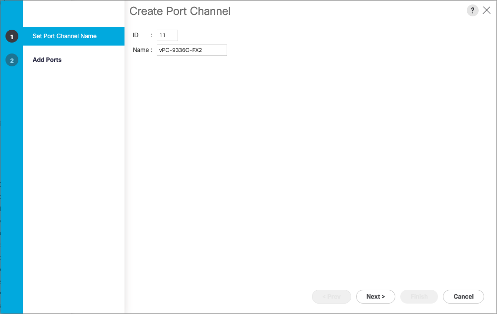
5. Enter 11 as the unique ID of the port channel.
![]() The Port Channel IDs in this example correspond to the first ports of upstream interface members of the Nexus leafs implementing the vPC, where 11 represents 1/1 on the switch. This is optional but can be helpful in correlating the Port Channel to the vPC.
The Port Channel IDs in this example correspond to the first ports of upstream interface members of the Nexus leafs implementing the vPC, where 11 represents 1/1 on the switch. This is optional but can be helpful in correlating the Port Channel to the vPC.
6. Enter vPC-9336C-FX2 as the name of the port channel.
7. Click Next.
8. Choose the uplink ports connected to the Nexus switches to be added to the port channel.
9. Click >> to add the ports to the port channel.
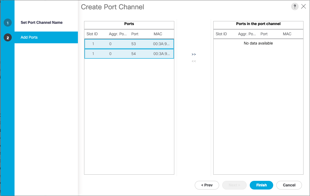
10. Click Finish to create the port channel.
11. Click OK.
12. In the navigation pane, under LAN > LAN Cloud > Fabric A > Port Channels, choose Port-Channel 11. Ensure Auto is selected for the Admin Speed. After a few minutes, verify that the Overall Status is Up, and the Operational Speed is correct.
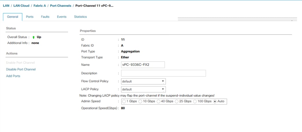
13. In the navigation pane, under LAN > LAN Cloud, expand the Fabric B tree.
14. Right-click Port Channels under Fabric B.
15. Choose Create Port Channel.
16. Enter 12 as the unique ID of the port channel.
17. Enter vPC-9336C-FX2 as the name of the port channel.
18. Click Next.
19. Choose the ports connected to the Nexus switches to be added to the port channel:
20. Click >> to add the ports to the port channel.
21. Click Finish to create the port channel.
22. Click OK.
23. In the navigation pane, under LAN > LAN Cloud > Fabric B > Port Channels, choose Port-Channel 12. Ensure Auto is selected for the Admin Speed. After a few minutes, verify that the Overall Status is Up, and the Operational Speed is correct.
Add UDLD to Uplink Port Channels
To configure the unidirectional link detection (UDLD) on the Uplink Port Channels to the Cisco Nexus switches for fibre optic connections, follow these steps:
1. In Cisco UCS Manager, click LAN.
2. Expand Policies > LAN Cloud > UDLD Link Policy.
3. Right-click UDLD Link Policy and choose Create UDLD Link Policy.
4. Name the Policy UDLD-Normal and choose Enabled for the Admin State and Normal for the Mode.
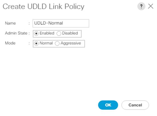
5. Click OK, then click OK again to complete creating the policy.
6. Expand Policies > LAN Cloud > Link Profile.
7. Right-click Link Profile and choose Create Link Profile.
8. Name the Profile UDLD-Normal and choose the UDLD-Normal Link Policy created above.
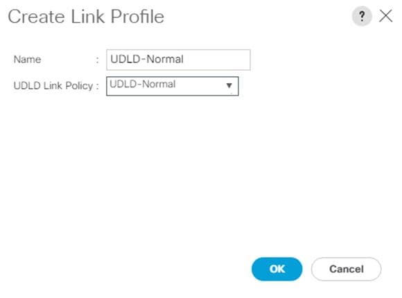
9. Click OK, then click OK again to complete creating the profile.
10. In the navigation pane, under LAN > LAN Cloud > Fabric A > Port Channels, expand Port-Channel 11. Choose the first Eth Interface under Port-Channel 11. From the drop-down list, choose the UDLD-Normal Link Profile created above, click Save Changes and OK. Repeat this process for each Eth Interface under Port-Channel 11 and for each Eth Interface under Port-Channel 12 on Fabric B.
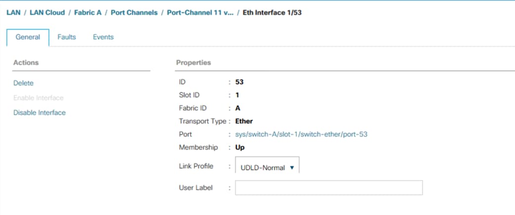
Set Jumbo Frames in Cisco UCS Fabric
Jumbo Frames are used in FlexPod for the NFS and iSCSI storage protocols. The typical best practice in FlexPod has been to set the MTU of the Best Effort QoS System Class in Cisco UCS Manager to 9216 for Jumbo Frames. In the Cisco UCS 6454 Fabric Interconnect with Cisco UCS Manager version 4.0 software the MTU for the Best Effort QoS System Class is fixed at normal and cannot be changed. With this setting of normal in the 6454, Jumbo Frames can pass through the Cisco UCS fabric without being dropped. In Cisco UCS Manager version 4.1, the MTU for the Best Effort QoS System Class is again settable. To configure jumbo frames in the Cisco UCS fabric, follow these steps:
1. In Cisco UCS Manager, click LAN.
2. Expand LAN > LAN Cloud > QoS System Class.
3. In the right pane, click the General tab.
4. On the Best Effort row, enter 9216 in the box under the MTU column.
5. Click Save Changes.
6. Click OK.
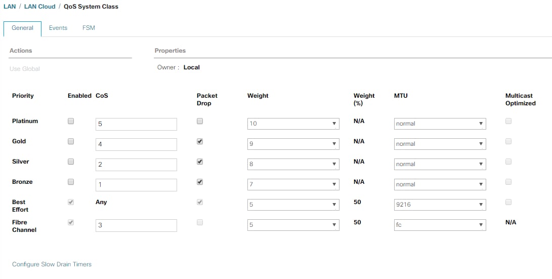
![]() Only the Fibre Channel and Best Effort QoS System Classes are enabled in this FlexPod implementation. The Cisco UCS and Cisco Nexus switches are intentionally configured this way so that all IP traffic within the FlexPod will be treated as Best Effort. Enabling the other QoS System Classes without having a comprehensive, end-to-end QoS setup in place can cause difficult to troubleshoot issues. For example, NetApp storage controllers by default mark IP-based, VLAN-tagged packets with a CoS value of 4. With the default configuration on the Cisco Nexus switches in this implementation, storage packets will pass through the switches and into the Cisco UCS Fabric Interconnects with CoS 4 set in the packet header. If the Gold QoS System Class in the Cisco UCS is enabled and the corresponding CoS value left at 4, these storage packets will be treated according to that class and if Jumbo Frames is being used for the storage protocols, but the MTU of the Gold QoS System Class is not set to Jumbo (9216), packet drops will occur. Note also that if the Platinum class is enabled, the MTU must be set to 9216 to use Jumbo Frames in that class.
Only the Fibre Channel and Best Effort QoS System Classes are enabled in this FlexPod implementation. The Cisco UCS and Cisco Nexus switches are intentionally configured this way so that all IP traffic within the FlexPod will be treated as Best Effort. Enabling the other QoS System Classes without having a comprehensive, end-to-end QoS setup in place can cause difficult to troubleshoot issues. For example, NetApp storage controllers by default mark IP-based, VLAN-tagged packets with a CoS value of 4. With the default configuration on the Cisco Nexus switches in this implementation, storage packets will pass through the switches and into the Cisco UCS Fabric Interconnects with CoS 4 set in the packet header. If the Gold QoS System Class in the Cisco UCS is enabled and the corresponding CoS value left at 4, these storage packets will be treated according to that class and if Jumbo Frames is being used for the storage protocols, but the MTU of the Gold QoS System Class is not set to Jumbo (9216), packet drops will occur. Note also that if the Platinum class is enabled, the MTU must be set to 9216 to use Jumbo Frames in that class.
Create VLANs
To configure the necessary virtual local area networks (VLANs) for the Cisco UCS environment, follow these steps:
1. In Cisco UCS Manager, click LAN.
![]() In this procedure, five unique VLANs are created. See Table2.
In this procedure, five unique VLANs are created. See Table2.
2. Expand LAN > LAN Cloud.
3. Right-click VLANs.
4. Choose Create VLANs.
5. Enter Native-VLAN as the name of the VLAN to be used as the native VLAN.
6. Keep the Common/Global option selected for the scope of the VLAN.
7. Enter the native VLAN ID.
8. Keep the Sharing Type as None.
9. Click OK and then click OK again.
10. Expand the list of VLANs in the navigation pane, right-click the newly created Native-VLAN and choose Set as Native VLAN.
11. Click Yes and then click OK.
12. Right-click VLANs.
13. Choose Create VLANs
14. Enter Site1-IB as the name of the VLAN to be used for management traffic (ESXi Hosts, site specific infrastructure).
![]() Modify these VLAN names as necessary for your environment.
Modify these VLAN names as necessary for your environment.
15. Keep the Common/Global option selected for the scope of the VLAN.
16. Enter the In-Band management VLAN ID.
17. Keep the Sharing Type as None.
18. Click OK, and then click OK again.
19. Right-click VLANs.
20. Choose Create VLANs.
21. Enter Common-IB as the name of the VLAN to be used for Common internal infrastructure (that may be relevant to application networks or differing locations)
22. Keep the Common/Global option selected for the scope of the VLAN.
23. Enter the Common Infrastructure VLAN ID.
24. Keep the Sharing Type as None.
25. Click OK, and then click OK again.
26. Right-click VLANs.
27. Choose Create VLANs.
28. Enter iSCSI-A as the name of the VLAN to be used for iSCSI-A traffic.
29. Keep the Common/Global option selected for the scope of the VLAN.
30. Enter the Infrastructure iSCSI-A VLAN ID.
31. Keep the Sharing Type as None.
32. Click OK, and then click OK again.
33. Right-click VLANs.
34. Choose Create VLANs.
35. Enter iSCSI-B as the name of the VLAN to be used for iSCSI-B traffic.
36. Keep the Common/Global option selected for the scope of the VLAN.
37. Enter the Infrastructure iSCSI-B VLAN ID.
38. Keep the Sharing Type as None.
39. Click OK, and then click OK again.
40. Right-click VLANs.
41. Choose Create VLANs.
42. Enter Infra-NFS as the name of the VLAN to be used for NFS.
43. Keep the Common/Global option selected for the scope of the VLAN.
44. Enter the Infrastructure NFS VLAN ID.
45. Keep the Sharing Type as None.
46. Click OK, and then click OK again.
47. Right-click VLANs.
48. Choose Create VLANs.
49. Enter vMotion as the name of the VLAN to be used for vMotion.
50. Keep the Common/Global option selected for the scope of the VLAN.
51. Enter the vMotion VLAN ID.
52. Keep the Sharing Type as None.
53. Click OK and then click OK again.
54. Choose Create VLANs.
55. Enter VM-Traffic as the name of the VLAN to be used for VM Traffic, or optionally add a “-“ to use as a prefix for multiple VLANs created.
56. Keep the Common/Global option selected for the scope of the VLAN.
57. Enter the VM-Traffic VLAN ID, or a range to use if creating multiple VLANs.
58. Keep the Sharing Type as None.
59. Click OK and then click OK again.
In this FlexPod implementation, MAC address pools are created at the root organization level to avoid MAC address pool overlaps. If your deployment plan calls for different MAC address ranges in different UCS organizations, place the MAC pools at the organizational level. To configure the necessary MAC address pools for the Cisco UCS environment, follow these steps:
1. In Cisco UCS Manager, click LAN.
2. Expand Pools > root.
![]() In this procedure, two MAC address pools are created, one for each switching fabric.
In this procedure, two MAC address pools are created, one for each switching fabric.
3. Right-click MAC Pools under the root organization.
4. Choose Create MAC Pool to create the MAC address pool.
5. Enter MAC-Pool-A as the name of the MAC pool.
6. Optional: Enter a description for the MAC pool.
7. Choose Sequential as the option for Assignment Order.
8. Click Next.
9. Click Add.
10. Specify a starting MAC address.
![]() For the FlexPod solution, the recommendation is to place A in the next-to-last octet of the starting MAC address to identify all of the MAC addresses as fabric A addresses. In our example, we have carried forward the example of also embedding the cabinet number information giving us 00:25:B5:A0:1A:00 as our first MAC address.
For the FlexPod solution, the recommendation is to place A in the next-to-last octet of the starting MAC address to identify all of the MAC addresses as fabric A addresses. In our example, we have carried forward the example of also embedding the cabinet number information giving us 00:25:B5:A0:1A:00 as our first MAC address.
11. Specify a size for the MAC address pool that is sufficient to support the available blade or server resources remembering that a server may contain multiple vNICs and that multiple unassociated Service Profiles can be created. In this example, with the MAC block modification, a maximum of 256 addresses are available.
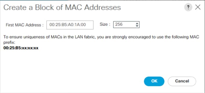
12. Click OK.
13. Click Finish.
14. In the confirmation message, click OK.
15. Right-click MAC Pools under the root organization.
16. Choose Create MAC Pool to create the MAC address pool.
17. Enter MAC-Pool-B as the name of the MAC pool.
18. Optional: Enter a description for the MAC pool.
19. Choose Sequential as the option for Assignment Order.
20. Click Next.
21. Click Add.
22. Specify a starting MAC address.
![]() For the FlexPod solution, it is recommended to place B in the next to last octet of the starting MAC address to identify all the MAC addresses in this pool as fabric B addresses. Once again, we have carried forward our example of also embedding the cabinet number information giving us 00:25:B5:A0:1B:00 as our first MAC address.
For the FlexPod solution, it is recommended to place B in the next to last octet of the starting MAC address to identify all the MAC addresses in this pool as fabric B addresses. Once again, we have carried forward our example of also embedding the cabinet number information giving us 00:25:B5:A0:1B:00 as our first MAC address.
23. Specify a size for the MAC address pool that is sufficient to support the available blade or server resources remembering that a server may contain multiple vNICs and that multiple unassociated Service Profiles can be created. In this example, with the MAC block modification, a maximum of 256 addresses are available.
24. Click OK.
25. Click Finish.
26. In the confirmation message, click OK.
Create Network Control Policy for Cisco Discovery Protocol (CDP) and Link Layer Discovery Protocol (LLDP)
To create a network control policy that enables CDP and LLDP on server virtual network controller (vNIC) ports, follow these steps:
1. In Cisco UCS Manager, click LAN.
2. Expand Policies > root.
3. Right-click Network Control Policies.
4. Choose Create Network Control Policy.
5. Enter Enable-CDP-LLDP as the policy name.
6. For CDP, choose the Enabled option.
7. For LLDP, scroll down and choose Enabled for both Transmit and Receive.
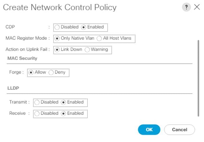
8. Click OK to create the network control policy.
9. Click OK.
To create multiple virtual network interface card (vNIC) templates within the FlexPod organization, follow these steps. A total of 6 vNIC Templates will be created. Two of the vNIC templates (vSwitch0-A and vSwitch0-B) will be created for vNICs to connect to VMware ESXi vSwitch0. vSwitch0 will have port groups for the IB-MGMT, Infra-NFS, vMotion, and VM-Traffic VLANs. The third and fourth vNIC templates (vDS0-A and vDS0-B) will be created for vNICs to connect to the VMware Virtual Distributed Switch (vDS0). The fifth and sixth vNIC templates will be used for the iSCSI A and iSCSI B.
The vDS will have port groups for the vMotion and VM-Traffic VLANs. Having the vMotion VMkernel on the vDS will allow the QoS marking of vMotion packets to occur within the vDS if QoS policies need to be applied to vMotion in the future. Any tenant or application VLANs can be placed on the vDS in the future.
![]() If QoS policy application to the vMotion packets will not be considered at some point, the vMotion VLAN can instead be placed on the vSwitch0-A and vSwitch0-B vNIC templates and handled as standard port groups in vSwitch0 alongside the rest of the infrastructure traffic.
If QoS policy application to the vMotion packets will not be considered at some point, the vMotion VLAN can instead be placed on the vSwitch0-A and vSwitch0-B vNIC templates and handled as standard port groups in vSwitch0 alongside the rest of the infrastructure traffic.
To create the infrastructure vNIC templates, follow these steps:
1. In Cisco UCS Manager, click LAN.
2. Expand Policies > root > Sub-Organizations > FlexPod.
3. Under the FlexPod Organization, right-click vNIC Templates.
4. Choose Create vNIC Template.
5. Enter vSwitch0-A as the vNIC template name.
6. Keep Fabric A selected.
7. Do not select the Enable Failover checkbox.
8. Choose Primary Template for Redundancy Type.
9. Leave the Peer Redundancy Template set to <not set>.
10. Under Target, make sure that only the Adapter checkbox is selected.
11. Choose Updating Template as the Template Type.
12. Under VLANs, choose the checkboxes for Common-IB, Site1-IB, Infra-NFS, and Native-VLAN VLANs.
13. Set Native-VLAN as the native VLAN.
14. Leave vNIC Name selected for the CDN Source.
15. For MTU, enter 9000.
16. In the MAC Pool list, choose MAC-Pool-A.
17. In the Network Control Policy list, choose CDP-LLDP.
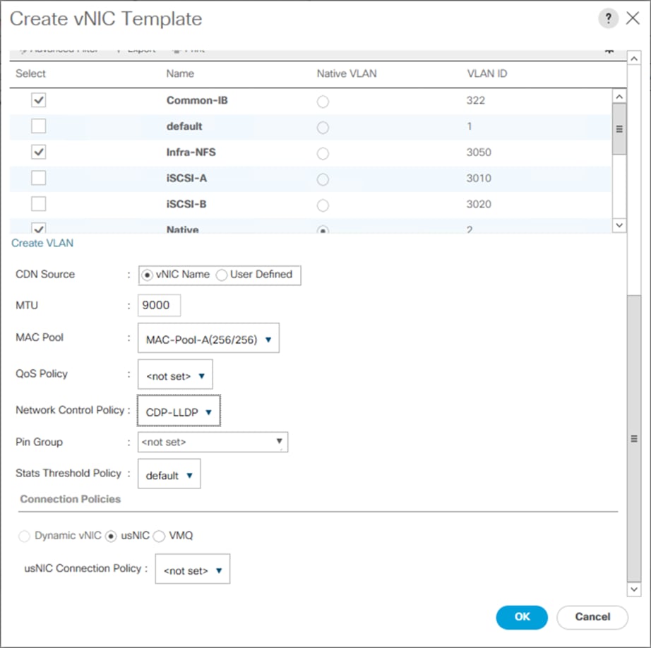
18. Click OK to create the vNIC template.
19. Click OK.
20. Under the FlexPod organization, right-click vNIC Templates.
21. Choose Create vNIC Template.
22. Enter vSwitch0-B as the vNIC template name.
23. Choose Fabric B.
24. Do not select the Enable Failover checkbox.
25. Set Redundancy Type to Secondary Template.
26. Choose vSwitch0-A for the Peer Redundancy Template.
27. In the MAC Pool list, choose MAC-Pool-B.
![]() The MAC Pool is all that needs to be selected for the Secondary Template, all other values will either be propagated from the Primary Template or set at default values.
The MAC Pool is all that needs to be selected for the Secondary Template, all other values will either be propagated from the Primary Template or set at default values.
28. Click OK to create the vNIC template.
29. Click OK.
30. Under the FlexPod Organization, right-click vNIC Templates.
31. Choose Create vNIC Template.
32. Enter vDS0-A as the vNIC template name.
33. Keep Fabric A selected.
34. Do not select the Enable Failover checkbox.
35. Choose Primary Template for Redundancy Type.
36. Leave the Peer Redundancy Template set to <not set>.
37. Under Target, make sure that only the Adapter checkbox is selected.
38. Choose Updating Template as the Template Type.
39. Under VLANs, choose the checkboxes for vMotion, any configured VM-Traffic VLANs, and the Native VLAN.
40. Set Native-VLAN as the native VLAN.
41. Leave vNIC Name selected for the CDN Source.
42. For MTU, enter 9000.
43. In the MAC Pool list, choose MAC-Pool-A.
44. In the Network Control Policy list, choose CDP-LLDP.
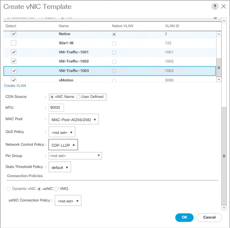
45. Click OK to create the vNIC template.
46. Click OK.
47. Under the FlexPod organization, right-click vNIC Templates.
48. Choose Create vNIC Template
49. Enter vDS0-B as the vNIC template name.
50. Choose Fabric B.
51. Do not select the Enable Failover checkbox.
52. Set Redundancy Type to Secondary Template.
53. Choose vDS0-A for the Peer Redundancy Template.
54. In the MAC Pool list, choose MAC-Pool-B.
![]() The MAC Pool is all that needs to be selected for the Secondary Template, all other values will either be propagated from the Primary Template or set at default values.
The MAC Pool is all that needs to be selected for the Secondary Template, all other values will either be propagated from the Primary Template or set at default values.
55. Click OK to create the vNIC template.
56. Click OK.
57. Under the FlexPod organization, right-click vNIC Templates.
58. Choose Create vNIC Template
59. Enter iSCSI-A as the vNIC template name.
60. Choose Fabric A. Do not choose the Enable Failover checkbox.
61. Leave Redundancy Type set at No Redundancy.
62. Under Target, make sure that only the Adapter checkbox is selected.
63. Choose Updating Template for Template Type.
64. Under VLANs, choose only iSCSI-A.
65. Choose iSCSI-A as the native VLAN.
66. Leave vNIC Name set for the CDN Source.
67. Under MTU, enter 9000.
68. From the MAC Pool list, choose MAC-Pool-A.
69. From the Network Control Policy list, choose CDP-LLDP.
70. Click OK to complete creating the vNIC template.
71. Click OK.
72. Right-click vNIC Templates.
73. Choose Create vNIC Template.
74. Enter iSCSI-B as the vNIC template name.
75. Choose Fabric B. Do not choose the Enable Failover checkbox.
76. Leave Redundancy Type set at No Redundancy.
77. Under Target, make sure that only the Adapter checkbox is selected.
78. Choose Updating Template for Template Type.
79. Under VLANs, choose only iSCSI-B.
80. Choose Infra-iSCSI-B as the native VLAN.
81. Leave vNIC Name set for the CDN Source.
82. Under MTU, enter 9000.
83. From the MAC Pool list, choose MAC-Pool-B.
84. From the Network Control Policy list, choose CDP-LLDP.
85. Click OK to complete creating the vNIC template.
86. Click OK.
Create High Traffic VMware Adapter Policy
To create the optional VMware-High-Traffic Ethernet Adapter policy to provide higher vNIC performance, follow these steps:
![]() This Ethernet Adapter policy can be attached to vNICs when creating the LAN Connectivity policy for vNICs that have large amounts of traffic on multiple flows or TCP sessions. This policy provides more hardware transmit and receive queues handled by multiple CPUs to the vNIC.
This Ethernet Adapter policy can be attached to vNICs when creating the LAN Connectivity policy for vNICs that have large amounts of traffic on multiple flows or TCP sessions. This policy provides more hardware transmit and receive queues handled by multiple CPUs to the vNIC.
1. In Cisco UCS Manager, click Servers.
2. Expand Policies > root.
3. Right-click Adapter Policies and choose Create Ethernet Adapter Policy.
4. Name the policy VMware-HighTrf.
5. Expand Resources and set the values as shown below.
![]() In this policy, Receive Queues can be set to 1-16. Completion Queues = Transmit Queues + Receive Queues. Interrupts = Completion Queues + 2. For more information, see Cisco UCS Manager Network Management Guide, Release 4.1, Network-Related Policies.
In this policy, Receive Queues can be set to 1-16. Completion Queues = Transmit Queues + Receive Queues. Interrupts = Completion Queues + 2. For more information, see Cisco UCS Manager Network Management Guide, Release 4.1, Network-Related Policies.
![]() Although previous versions of this document set the Ring Sizes for the Transmit and Receive Queues to 4096, Tuning Guidelines for Cisco UCS Virtual Interface Cards states that the sizes should be increased only if packet drops are observed on the vNIC interfaces.
Although previous versions of this document set the Ring Sizes for the Transmit and Receive Queues to 4096, Tuning Guidelines for Cisco UCS Virtual Interface Cards states that the sizes should be increased only if packet drops are observed on the vNIC interfaces.
6. Expand Options and choose Enabled for Receive Side Scaling (RSS).
7. Click OK, then click OK again to complete creating the Ethernet Adapter Policy.
Create LAN Connectivity Policy for iSCSI Boot
To configure the necessary Infrastructure LAN Connectivity Policy within the FlexPod Organization, follow these steps:
1. In Cisco UCS Manager, click LAN.
2. Expand LAN > Policies > root > Sub-Organizations > FlexPod Organization.
3. Right-click LAN Connectivity Policies under the FlexPod Organization.
4. Choose Create LAN Connectivity Policy.
5. Enter iSCSI-Boot as the name of the policy.
6. Click OK then OK again to create the policy.
7. On the left under LAN > Policies > root > Sub-Organizations > FlexPod Organization > LAN Connectivity Policies, choose iSCSI-Boot.
8. Click the Add button to add a vNIC.
9. In the Create vNIC dialog box, enter 00-vSwitch0-A as the name of the vNIC.
10. Choose the Use vNIC Template checkbox.
11. In the vNIC Template list, choose vSwitch0-A.
12. In the Adapter Policy list, choose VMWare.
13. Click OK to add this vNIC to the policy.
14. Click Save Changes and OK.
15. Click the Add button to add another vNIC to the policy.
16. In the Create vNIC box, enter 01-vSwitch0-B as the name of the vNIC.
17. Choose the Use vNIC Template checkbox.
18. In the vNIC Template list, choose vSwitch0-B.
19. In the Adapter Policy list, choose VMWare.
20. Click OK to add the vNIC to the policy.
21. Click Save Changes and OK.
22. Click the Add button to add a vNIC.
23. In the Create vNIC dialog box, enter 02-vDS0-A as the name of the vNIC.
24. Choose the Use vNIC Template checkbox.
25. In the vNIC Template list, choose vDS0-A.
26. In the Adapter Policy list, choose VMWare-HighTrf.
27. Click OK to add this vNIC to the policy.
28. Click Save Changes and OK.
29. Click the Add button to add another vNIC to the policy.
30. In the Create vNIC box, enter 03-vDS0-B as the name of the vNIC.
31. Choose the Use vNIC Template checkbox.
32. In the vNIC Template list, choose vDS0-B.
33. In the Adapter Policy list, choose VMWare-HighTrf.
34. Click OK to add the vNIC to the policy.
35. Click Save Changes and OK.
36. Click the Add button to add a vNIC.
37. In the Create vNIC dialog box, enter 04-iSCSI-A as the name of the vNIC.
38. Choose the Use vNIC Template checkbox.
39. In the vNIC Template list, choose iSCSI-A.
40. In the Adapter Policy list, choose VMWare.
41. Click OK to add this vNIC to the policy.
42. Click Save Changes and OK.
43. Click Add to add a vNIC to the policy.
44. In the Create vNIC dialog box, enter 05-iSCSI-B as the name of the vNIC.
45. Choose the Use vNIC Template checkbox.
46. In the vNIC Template list, choose iSCSI-B.
47. In the Adapter Policy list, choose VMWare.
48. Click OK to add this vNIC to the policy.
49. Click Save Changes and OK.
50. Expand Add iSCSI vNICs.
51. Choose Add in the Add iSCSI vNICs section.
52. Set the name to iSCSI-Boot-A.
53. Choose 04-iSCSI-A as the Overlay vNIC.
54. Set the iSCSI Adapter Policy to default.
55. Leave the VLAN set to Infra-iSCSI-A (native).
56. Leave the MAC Address set to None.
57. Click OK.
58. Click Save Changes and OK.
59. Choose Add in the Add iSCSI vNICs section.
60. Set the name to iSCSI-Boot-B.
61. Choose 05-iSCSI-B as the Overlay vNIC.
62. Set the iSCSI Adapter Policy to default.
63. Leave the VLAN set to Infra-iSCSI-B (native).
64. Leave the MAC Address set to None.
65. Click OK then click OK again.
Create IQN Pools for iSCSI Boot
To configure the necessary IQN pools for the Cisco UCS environment, follow these steps:
1. In Cisco UCS Manager, click SAN.
2. Expand Pools > root.
3. Right-click IQN Pools.
4. Choose Create IQN Suffix Pool to create the IQN pool.
5. Enter IQN-Pool for the name of the IQN pool.
6. Optional: Enter a description for the IQN pool.
7. Enter iqn.2010-11.com.flexpod as the prefix.
8. Choose Sequential for Assignment Order.
9. Click Next.
10. Click Add.
11. Enter ucs-host as the suffix.
![]() If multiple Cisco UCS domains are being used, a more specific IQN suffix may need to be used.
If multiple Cisco UCS domains are being used, a more specific IQN suffix may need to be used.
12. Enter 1 in the From field.
13. Specify the size of the IQN block sufficient to support the available server resources.
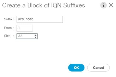
14. Click OK.
15. Click Finish and then click OK to complete creating the IQN pool.
To configure the necessary server pool for the Cisco UCS environment in the FlexPod Organization, follow these steps:
![]() Consider creating unique server pools to achieve the granularity that is required in your environment.
Consider creating unique server pools to achieve the granularity that is required in your environment.
1. In Cisco UCS Manager, click Servers.
2. Expand Pools > root > Sub-Organizations > FlexPod.
3. Right-click Server Pools under the FlexPod Organization.
4. Choose Create Server Pool.
5. Enter Infra-Pool as the name of the server pool.
6. Optional: Enter a description for the server pool.
7. Click Next.
8. Choose three (or more) servers to be used for the VMware management cluster and click >> to add them to the Infra-Pool server pool.
![]() Although the VMware minimum host cluster size is two, in most use cases three servers are recommended.
Although the VMware minimum host cluster size is two, in most use cases three servers are recommended.
9. Click Finish.
To configure the necessary universally unique identifier (UUID) suffix pool for the Cisco UCS environment, follow these steps:
1. In Cisco UCS Manager, click Servers.
2. Expand Pools > root.
3. Right-click UUID Suffix Pools.
4. Choose Create UUID Suffix Pool.
5. Enter UUID-Pool as the name of the UUID suffix pool.
6. Optional: Enter a description for the UUID suffix pool.
7. Keep the prefix at the derived option.
8. Choose Sequential for the Assignment Order.
9. Click Next.
10. Click Add to add a block of UUIDs.
11. Keep the From field at the default setting.
12. Specify a size for the UUID block that is sufficient to support the available blade or server resources and the number of Service Profiles that will be created.
13. Click OK.
14. Click Finish.
15. Click OK.
Modify Default Host Firmware Package
Firmware management policies allow the administrator to choose the corresponding packages for a given server configuration. These policies often include packages for adapter, BIOS, board controller, FC adapters, host bus adapter (HBA) option ROM, and storage controller properties.
To modify the default firmware management policy in the Cisco UCS environment, follow these steps:
1. In Cisco UCS Manager, click Servers.
2. Expand Policies > root.
3. Expand Host Firmware Packages.
4. Choose default.
5. In the Actions pane, choose Modify Package Versions.
6. Choose version 4.1(2a) for both the Blade and Rack Packages.
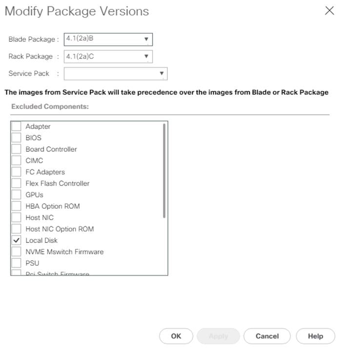
7. Click OK, then click OK again to modify the host firmware package.
Create Local Disk Configuration Policy (Optional)
A local disk configuration specifying no local disks for the Cisco UCS environment can be used to ensure that servers with no local disks are used for SAN Boot.
![]() This policy should not be used on servers that contain local disks.
This policy should not be used on servers that contain local disks.
To create a local disk configuration policy, follow these steps:
1. In Cisco UCS Manager, click Servers.
2. Expand Policies > root.
3. Right-click Local Disk Config Policies.
4. Choose Create Local Disk Configuration Policy.
5. Enter SAN-Boot as the local disk configuration policy name.
6. Change the mode to No Local Storage.
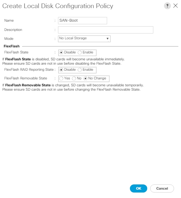
7. Click OK to create the local disk configuration policy.
8. Click OK.
To create a power control policy for the Cisco UCS environment, follow these steps:
1. In Cisco UCS Manager, click Servers.
2. Expand Policies > root.
3. Right-click Power Control Policies.
4. Choose Create Power Control Policy.
5. Enter No-Power-Cap as the power control policy name.
6. Change the power capping setting to No Cap.
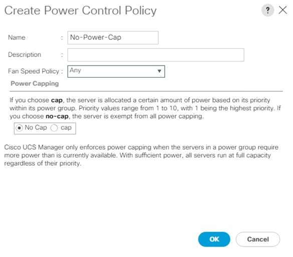
7. Click OK to create the power control policy.
8. Click OK.
Create Server Pool Qualification Policy (Optional)
To create an optional server pool qualification policy for the Cisco UCS environment, follow these steps:
![]() This example creates a policy for Cisco UCS B200 M5 servers for a server pool.
This example creates a policy for Cisco UCS B200 M5 servers for a server pool.
1. In Cisco UCS Manager, click Servers.
2. Expand Policies > root.
3. Right-click Server Pool Policy Qualifications.
4. Choose Create Server Pool Policy Qualification.
5. Name the policy UCS-B200-M5.
6. Choose Create Server PID Qualifications.
7. Choose UCSB-B200-M5 from the PID drop-down list.
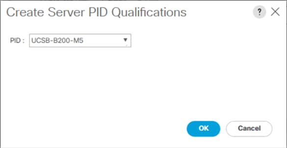
8. Click OK
9. Optionally choose additional qualifications to refine server selection parameters for the server pool.
10. Click OK to create the policy then OK for the confirmation.
Update the Default Maintenance Policy
To update the default Maintenance Policy to either require user acknowledgement before server boot when service profiles change or to make the changes on the next server reboot, follow these steps:
1. In Cisco UCS Manager, click Servers.
2. Expand Policies > root.
3. Choose Maintenance Policies > default.
4. Change the Reboot Policy to User Ack.
5. Choose “On Next Boot” to delegate maintenance windows to server administrators.
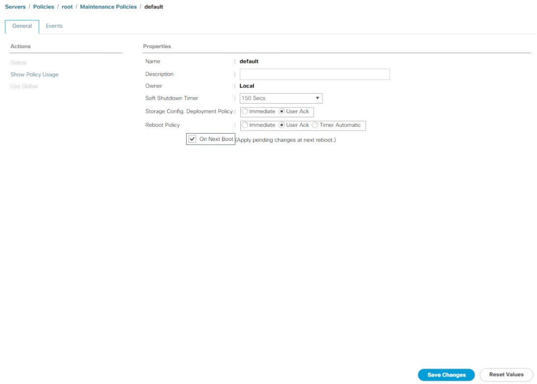
6. Click Save Changes.
7. Click OK to accept the changes.
Create vMedia Policy for VMware ESXi 7.0 ISO Install Boot
In the NetApp ONTAP setup steps, an HTTP web server is required, which is used for hosting ONTAP as well as VMware software. The vMedia Policy created will map the Cisco Custom ISO for UCS 4.1.2a to the Cisco UCS server in order to boot the ESXi installation. To create this policy, follow these steps:
1. In Cisco UCS Manager, choose Servers.
2. Expand Policies > root.
3. Right-click vMedia Policies.
4. Choose Create vMedia Policy.
5. Name the policy ESXi-7.0-HTTP.
6. Enter “Mounts Cisco Custom ISO ESXi7 for UCS 4.1(2a)” in the Description field.
7. Click Add to add a vMedia Mount.
8. Name the mount ESXi-7.0-HTTP.
9. Choose the CDD Device Type.
10. Choose the HTTP Protocol.
11. Enter the IP Address of the web server.
![]() To avoid any DNS lookup issues, enter the IP of the web server instead of the hostname.
To avoid any DNS lookup issues, enter the IP of the web server instead of the hostname.
12. Enter VMware-ESXi-7.0.0-16324942-Custom-Cisco-4.1.2a.iso as the Remote File name.
![]() This VMware ESXi 7.0 Cisco Custom ISO can be downloaded from VMware Downloads.
This VMware ESXi 7.0 Cisco Custom ISO can be downloaded from VMware Downloads.
13. Enter the web server path to the ISO file in the Remote Path field.
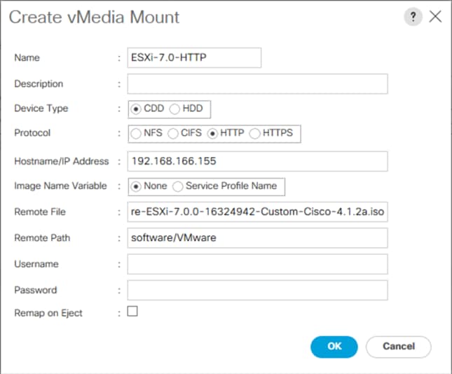
14. Click OK to create the vMedia Mount.
15. Click OK then click OK again to complete creating the vMedia Policy.
![]() For any new servers added to the Cisco UCS environment the vMedia service profile template can be used to install the ESXi host. On first boot the host will boot into the ESXi installer since the iSCSI mounted disk is empty. After ESXi is installed, the vMedia will not be referenced as long as the boot disk is accessible.
For any new servers added to the Cisco UCS environment the vMedia service profile template can be used to install the ESXi host. On first boot the host will boot into the ESXi installer since the iSCSI mounted disk is empty. After ESXi is installed, the vMedia will not be referenced as long as the boot disk is accessible.
To create a server BIOS policy for VMware ESXi hosts within the FlexPod organization, follow these steps:
1. In Cisco UCS Manager, click Servers.
2. Expand Policies > root > Sub-Organizations > FlexPod.
3. Right-click BIOS Policies under FlexPod Organization.
4. Choose Create BIOS Policy.
5. Enter Intel-VM-Host as the BIOS policy name.
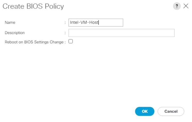
6. Click OK, then click OK again to create the BIOS Policy.
7. Under the FlexPod Organization, expand BIOS Policies and choose the newly created BIOS Policy. Set the following within the Main tab of the Policy:
a. CDN Control -> Enabled
b. Quiet Boot -> Disabled
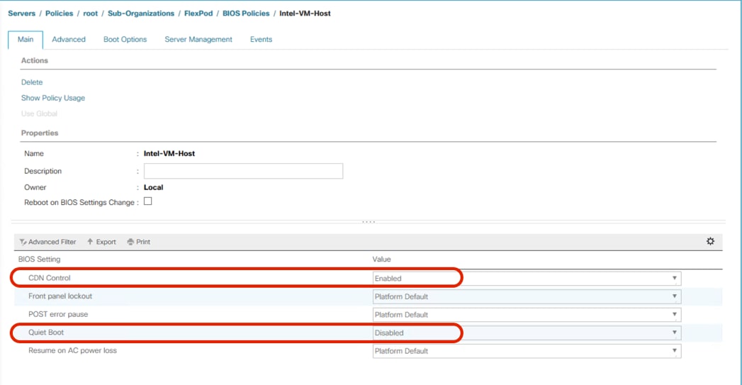
8. Click the Advanced tab, leaving the Processor tab selected within the Advanced tab. Set the following within the Processor tab:
a. Processor C State -> Disabled
b. Processor C1E -> Disabled
c. Processor C3 Report -> Disabled
d. Processor C6 Report -> Disabled
e. Processor C7 Report -> Disabled
f. Power Technology -> Custom
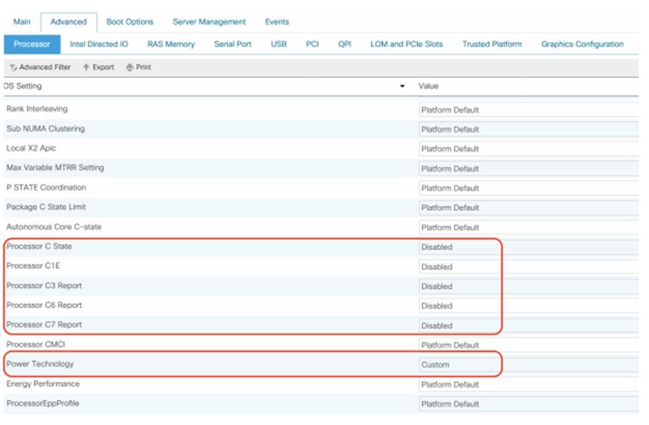
9. Click the RAS Memory tab, and choose:
a. NVM Performance Setting -> Balanced Profile
b. Memory RAS configuration -> Maximum Performance
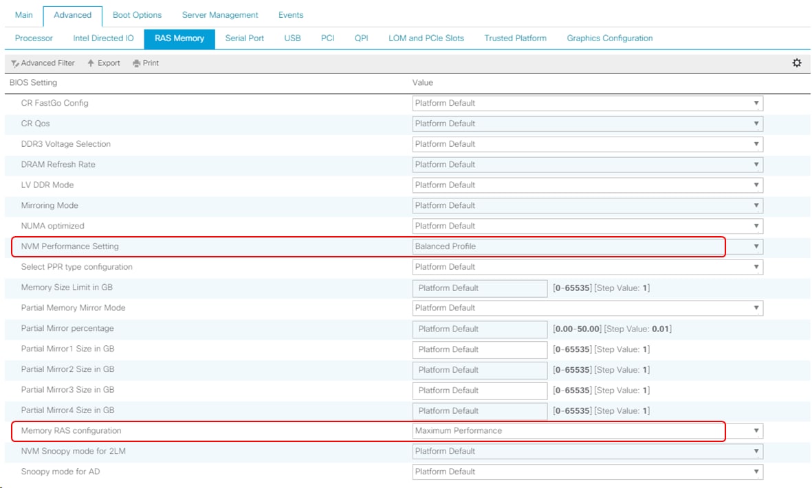
10. Click Save Changes.
11. Click OK.
Create iSCSI Boot Policy
This procedure applies to a Cisco UCS environment in which two iSCSI logical interfaces (LIFs) are on cluster node 1 (iscsi-lif01a and iscsi-lif01b) and two iSCSI LIFs are on cluster node 2 (iscsi-lif02a and iscsi-lif02b). Also, it is assumed that the A LIFs are connected to Fabric A (Cisco UCS Fabric Interconnect A) and the B LIFs are connected to Fabric B (Cisco UCS Fabric Interconnect B).
![]() One boot policy is configured in this procedure. The policy configures the primary target to be iscsi-lif01a.
One boot policy is configured in this procedure. The policy configures the primary target to be iscsi-lif01a.
To create a boot policy for the Cisco UCS environment within the FlexPod Organization, follow these steps:
1. In Cisco UCS Manager, click Servers.
2. Expand Policies > root > Sub-Organizations > FlexPod Organization.
3. Right-click Boot Policies under the FlexPod Organization.
4. Choose Create Boot Policy.
5. Enter Boot-iSCSI-A as the name of the boot policy.
6. Optional: Enter a description for the boot policy.
7. Do not choose the Reboot on Boot Order Change checkbox.
8. Choose the Uefi Boot Mode.
9. Check the checkbox for Boot Security.
10. Expand the Local Devices drop-down list and click Add Remote CD/DVD.
11. Expand the iSCSI vNICs drop-down list and click Add iSCSI Boot.
12. In the Add iSCSI Boot dialog box, enter iSCSI-Boot-A.
13. Click OK.
14. Choose Add iSCSI Boot.
15. In the Add iSCSI Boot dialog box, enter iSCSI-Boot-B.
16. Click OK.
17. Expand CIMC Mounted Media and select Add CIMC Mounted CD/DVD.
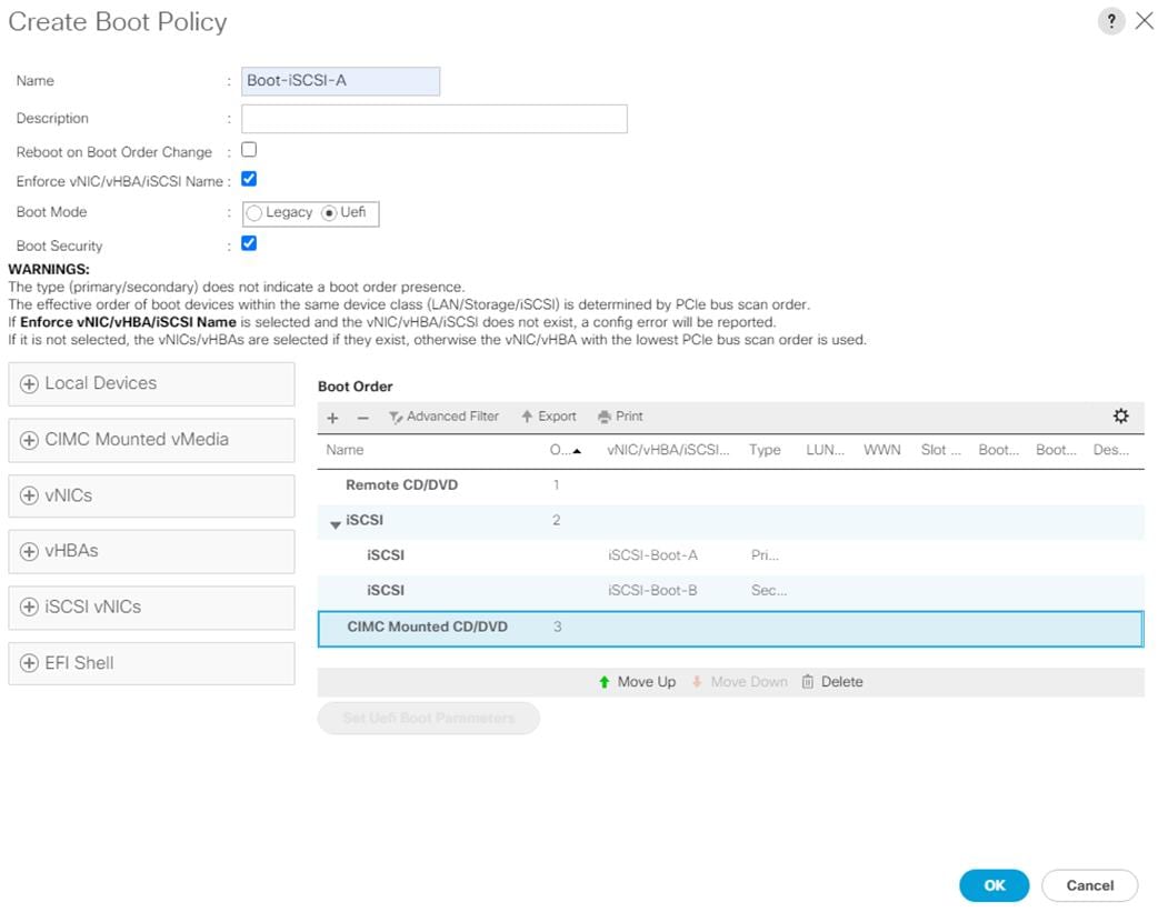
18. Expand iSCSI and select iSCSI Target Primary. Select Set Uefi Boot Parameters.
![]() For Cisco UCS B200 M5 and Cisco UCS C220 M5 servers it is not necessary to set the Uefi Boot Parameters. These servers will boot properly with or without these parameters set. However, for M4 and earlier servers, VMware ESXi 7.0 will not boot with Uefi Secure Boot unless these parameters are set exactly as shown.
For Cisco UCS B200 M5 and Cisco UCS C220 M5 servers it is not necessary to set the Uefi Boot Parameters. These servers will boot properly with or without these parameters set. However, for M4 and earlier servers, VMware ESXi 7.0 will not boot with Uefi Secure Boot unless these parameters are set exactly as shown.
19. Fill-in the Set Uefi Boot Parameters exactly as shown in the following screenshot:
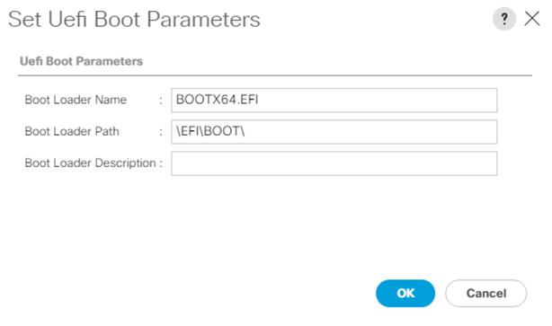
20. Click OK to complete setting the Uefi Boot Parameters for the SAN Boot Target and click OK for the confirmation.
21. Repeat this process to set Uefi Boot Parameters for the Secondary iSCSI Boot Targets.
22. Click OK then click OK again to create the policy.
Create iSCSI Boot Service Profile Template
In this procedure, one service profile template for Infrastructure ESXi hosts within the FlexPod Organization is created for Fabric A boot.
To create the service profile template, follow these steps:
1. In Cisco UCS Manager, click Servers.
2. Expand Service Profile Templates > root > Sub-Organizations > FlexPod Organization.
3. Right-click the FlexPod Organization.
4. Choose Create Service Profile Template to open the Create Service Profile Template wizard.
5. Enter Intel-VM-Host-Infra-iSCSI-A as the name of the service profile template. This service profile template is configured to boot from storage node 1 on fabric A.
6. Choose the Updating Template option.
7. Under UUID Assignment, choose UUID-Pool.
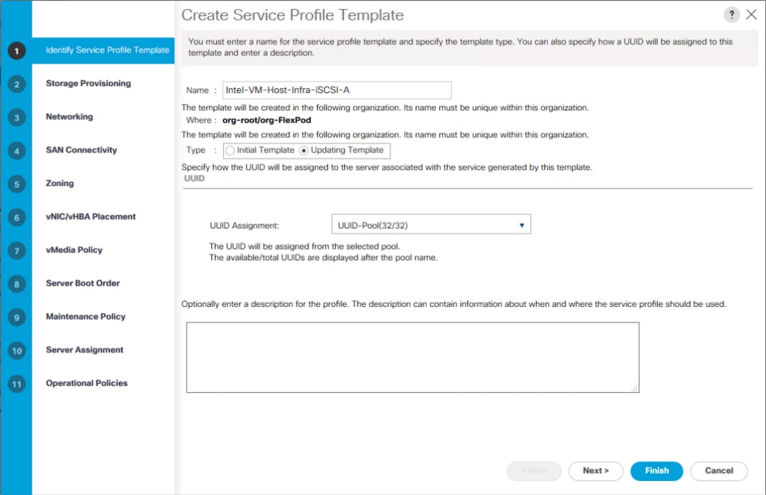
8. Click Next.
Configure Storage Provisioning
To configure the storage provisioning, follow these steps:
1. If you have servers with no physical disks, click on the Local Disk Configuration Policy tab and choose the SAN-Boot Local Storage Policy. Otherwise, choose the default Local Storage Policy.
2. Click Next.
Configure Networking Options
To configure the network options, follow these steps:
1. Choose the “Use Connectivity Policy” option to configure the LAN connectivity.
2. Choose iSCSI-Boot from the LAN Connectivity Policy drop-down list.
3. Choose IQN_Pool in Initiator Name Assignment.
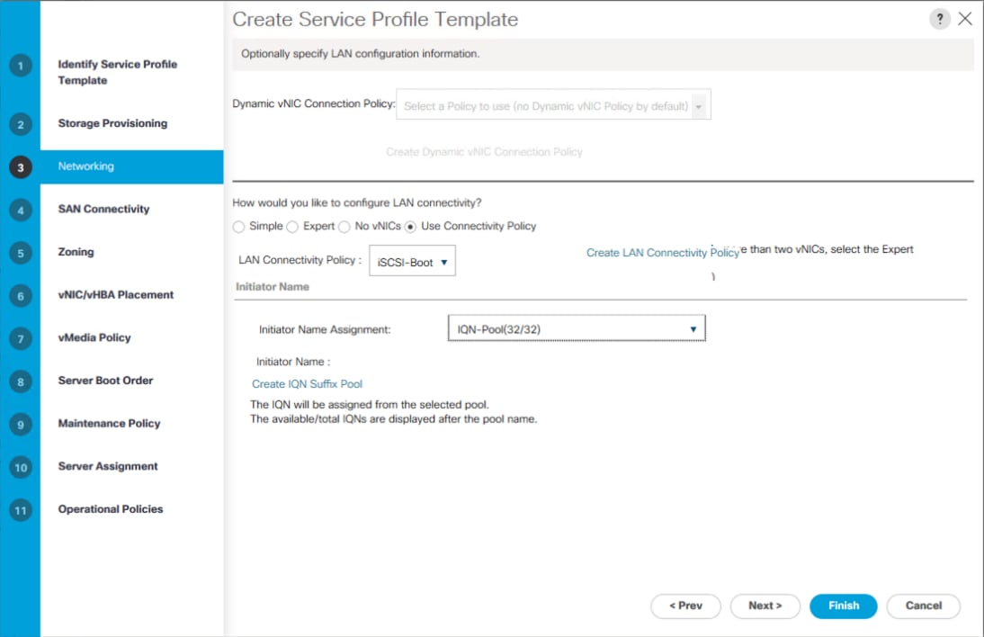
4. Click Next.
Configure Storage Options
To configure the storage options, follow these steps:
1. Choose No vHBAs for the “How would you like to configure SAN connectivity?” field.
2. Click Next.
Configure Zoning Options
To configure the zoning options, follow this step:
1. Make no changes and click Next.
Configure vNIC/HBA Placement
To configure the vNIC/HBA placement, follow these steps:
1. In the “Select Placement” list, leave the placement policy as “Let System Perform Placement”.
2. Click Next.
Configure vMedia Policy
To configure the vMedia policy, follow these steps:
1. Do not select a vMedia Policy.
2. Click Next.
Configure Server Boot Order
To configure the server boot orders, follow these steps:
1. Choose Boot-iSCSI-A for Boot Policy.
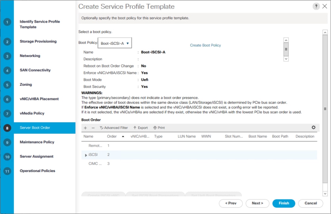
2. In the Boot order, expand iSCSI and choose iSCSI-Boot-A.
3. Click Set iSCSI Boot Parameters.
4. In the Set iSCSI Boot Parameters pop-up, leave Authentication Profile to <not set> unless you have in-dependently created one appropriate to your environment.
5. Leave the “Initiator Name Assignment” dialog box <not set> to use the single Service Profile Initiator Name defined in the previous steps.
6. Set iSCSI-IP-Pool-A as the “Initiator IP address Policy.”
7. Choose iSCSI Static Target Interface option.
8. Click Add.
9. Enter the iSCSI Target Name. To get the iSCSI target name of Infra-SVM, log into the storage cluster management interface and run the “iscsi show” command”.
10. Enter the IP address of iscsi-lif-1a for the IPv4 Address field.
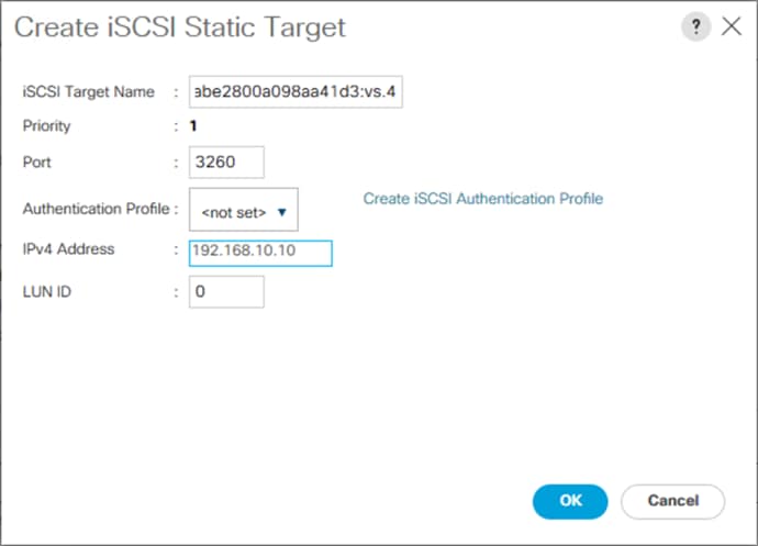
11. Click OK to add the iSCSI static target.
12. Click Add.
13. Enter the iSCSI Target Name.
14. Enter the IP address of iscsi-lif-2a for the IPv4 Address field.
15. Click OK to add the iSCSI static target.
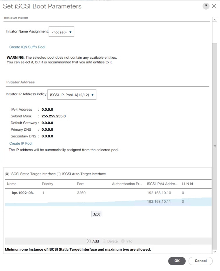
16. Click OK to complete setting the iSCSI Boot Parameters.
17. In the Boot order, choose iSCSI-Boot-B.
18. Click Set iSCSI Boot Parameters.
19. In the Set iSCSI Boot Parameters pop-up, leave Authentication Profile to <not set> unless you have in-dependently created one appropriate to your environment.
20. Leave the “Initiator Name Assignment” dialog box <not set> to use the single Service Profile Initiator Name defined in the previous steps.
21. Set iSCSI-IP-Pool-B as the “Initiator IP address Policy”.
22. Choose the iSCSI Static Target Interface option.
23. Click Add.
24. Enter the iSCSI Target Name. To get the iSCSI target name of Infra-SVM, login into storage cluster management interface and run “iscsi show” command”.
25. Enter the IP address of iscsi-lif-01b for the IPv4 Address field.
26. Click OK to add the iSCSI static target.
27. Click Add.
28. Enter the iSCSI Target Name.
29. Enter the IP address of iscsi-lif-02b for the IPv4 Address field.
30. Click OK to add the iSCSI static target.
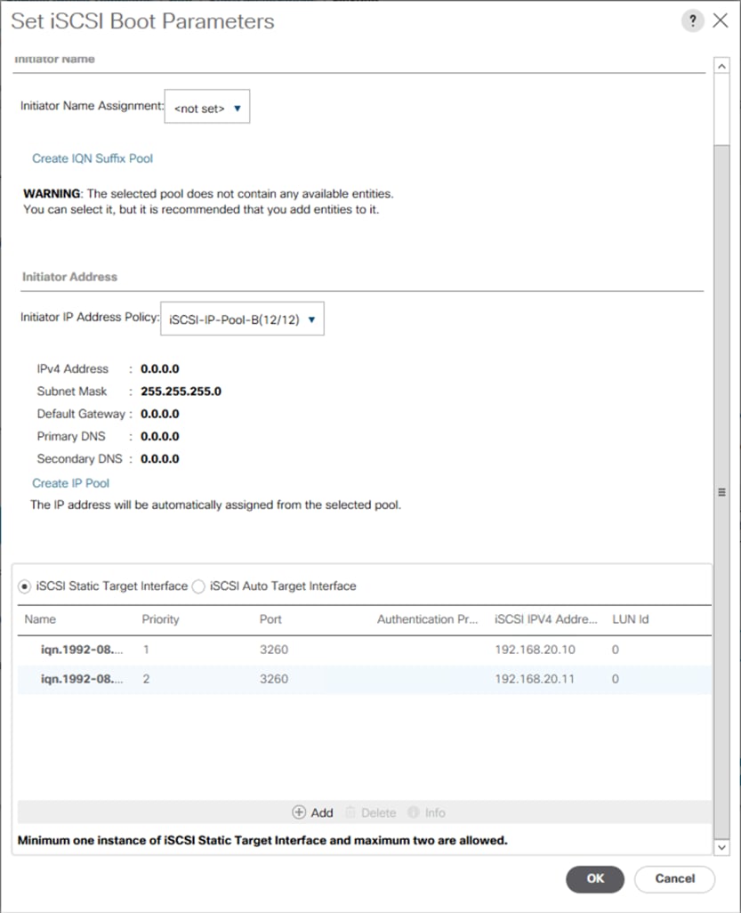
31. Click OK to complete setting the iSCSI Boot Parameters.
32. Click Next.
Configure Maintenance Policy
To configure the maintenance policy, follow these steps:
1. Change the Maintenance Policy to default.
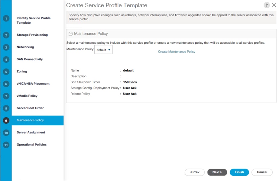
2. Click Next.
Configure Server Assignment
To configure server assignment, follow these steps:
1. In the Pool Assignment list, choose Infra-Pool.
2. Choose Down as the power state to be applied when the profile is associated with the server.
3. Optional: choose “UCS-B200M5” for the Server Pool Qualification to select only UCS B200M5 servers in the pool.
4. Expand Firmware Management at the bottom of the page and choose the default policy.
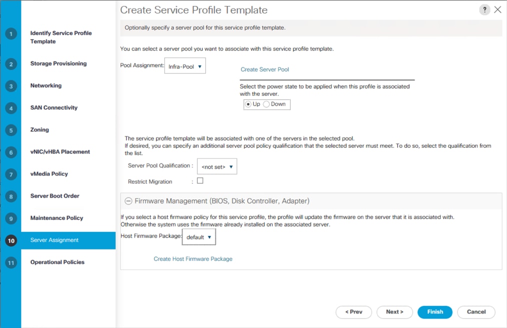
5. Click Next.
Configure Operational Policies
To configure the operational policies, follow these steps:
1. In the BIOS Policy list, choose Intel-VM-Host.
2. Expand Power Control Policy Configuration and choose No-Power-Cap in the Power Control Policy list.
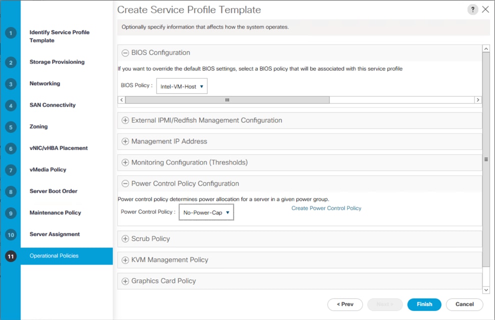
3. Click Finish to create the service profile template.
4. Click OK in the confirmation message.
Create vMedia-Enabled Service Profile Template
To create a service profile template with vMedia enabled, follow these steps:
1. Connect to Cisco UCS Manager and click Servers.
2. Choose Service Profile Templates > root > Sub-Organizations > FlexPod Organization > Service Template Intel-VM-Host-Infra-iSCSI-A.
3. Right-click Intel-VM-Host-Infra-iSCSI-A and click Create a Clone.
4. Name the clone Intel-VM-Host-Infra-iSCSI-A-vM and click OK then click OK again to create the clone.
5. Choose the newly created Intel-VM-Host-Infra-iSCSI-A-vM and choose the vMedia Policy tab.
6. Click Modify vMedia Policy.
7. Choose the ESXi-7.0-HTTP vMedia Policy and click OK.
8. Click OK to confirm.
Create Service Profiles
To create service profiles from the service profile template, follow these steps:
1. Connect to Cisco UCS Manager and click Servers.
2. Expand Service Profile Templates > root > Sub-Organizations > FlexPod Organization.
3. Right-click the appropriate vMedia-enabled template and choose Create Service Profiles from Template.
4. For Naming Prefix, enter VM-Host-Infra-0.
5. For Name Suffix Starting Number, enter 1.
6. For Number of Instances, enter 5.
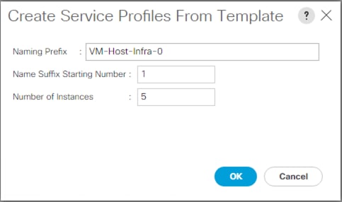
![]() Previously created server pool was for the 3 Cisco UCS B200s, the generated Service Profiles for the remaining Cisco UCS C220s were manually associated. Server pool qualifications and server associations should be created to address what is appropriate to the customers environment.
Previously created server pool was for the 3 Cisco UCS B200s, the generated Service Profiles for the remaining Cisco UCS C220s were manually associated. Server pool qualifications and server associations should be created to address what is appropriate to the customers environment.
7. Click OK to create the service profiles.
8. Click OK in the confirmation message.
9. When VMware ESXi 7.0 has been installed on the hosts, the host Service Profiles can be bound to the corresponding non-vMedia-enabled Service Profile Template to remove the vMedia Mapping from the host.
Storage Configuration - Boot LUNs and Igroups
Gather Required Information
| SVM Name |
SVM Target IQN |
| Infra-SVM |
|
![]() To obtain the iSCSI IQN, run iscsi show command on the storage cluster management interface.
To obtain the iSCSI IQN, run iscsi show command on the storage cluster management interface.
| Cisco UCS Service Profile Name |
iSCSI IQN |
Variable |
| VM-Host-Infra-01 |
|
<vm-host-infra-01-iqn> |
| VM-Host-Infra-02 |
|
<vm-host-infra-02-iqn> |
| VM-Host-Infra-03 |
|
<vm-host-infra-03-iqn> |
| VM-Host-Infra-04 |
|
<vm-host-infra-04-iqn> |
| VM-Host-Infra-05 |
|
<vm-host-infra-05-iqn> |
![]() To obtain the iSCSI vNIC IQN information in Cisco UCS Manager GUI, go to Servers > Service Profiles > root. Click each service profile and then click the “iSCSI vNICs” tab on the top right. The “Initiator Name” is displayed at the top of the page under the “Service Profile Initiator Name.”
To obtain the iSCSI vNIC IQN information in Cisco UCS Manager GUI, go to Servers > Service Profiles > root. Click each service profile and then click the “iSCSI vNICs” tab on the top right. The “Initiator Name” is displayed at the top of the page under the “Service Profile Initiator Name.”
Create igroups
Create igroups by entering the following commands from the storage cluster management LIF SSH connection:
lun igroup create –vserver Infra-SVM –igroup vm-host-infra-01 –protocol iscsi –ostype vmware –initiator <vm-host-infra-01-iqn>
lun igroup create –vserver Infra-SVM –igroup vm-host-infra-02 –protocol iscsi –ostype vmware –initiator <vm-host-infra-02-iqn>
lun igroup create –vserver Infra-SVM –igroup vm-host-infra-03 –protocol iscsi –ostype vmware –initiator <vm-host-infra-03-iqn>
lun igroup create –vserver Infra-SVM –igroup vm-host-infra-04 –protocol iscsi –ostype vmware –initiator <vm-host-infra-04-iqn>
lun igroup create –vserver Infra-SVM –igroup vm-host-infra-05 –protocol iscsi –ostype vmware –initiator <vm-host-infra-05-iqn>
lun igroup show -protocol iscsi
Map Boot LUNs to igroups
To map the boot LUNs to igroups use the following commands:
lun mapping create –vserver Infra-SVM –path /vol/esxi_boot/VM-Host-Infra-01 –igroup vm-host-infra-01 –lun-id 0
lun mapping create –vserver Infra-SVM –path /vol/esxi_boot/ VM-Host-Infra-02 –igroup vm-host-infra-02 –lun-id 0
lun mapping create –vserver Infra-SVM –path /vol/esxi_boot/ VM-Host-Infra-03 –igroup vm-host-infra-03 –lun-id
lun mapping create –vserver Infra-SVM –path /vol/esxi_boot/ VM-Host-Infra-04 –igroup vm-host-infra-04 –lun-id
lun mapping create –vserver Infra-SVM –path /vol/esxi_boot/ VM-Host-Infra-05 –igroup vm-host-infra-05 –lun-id 0
Solution Deployment - VMware vSphere
VMware ESXi 7.0
This section provides detailed instructions for installing VMware ESXi 7.0 in a FlexPod environment. After the procedures are completed, three booted ESXi hosts will be provisioned.
Several methods exist for installing ESXi in a VMware environment. These procedures focus on how to use the built-in keyboard, video, mouse (KVM) console and virtual media features in Cisco UCS Manager to map remote installation media to individual servers and connect to their boot logical unit numbers (LUNs).
If the VMware ESXi ISO has not already been downloaded, follow these steps:
1. Click the following link: Cisco Custom ISO for UCS 4.1.2a.
2. You will need a user id and password on vmware.com to download this software.
3. Download the .iso file.
Log into Cisco UCS 6454 Fabric Interconnect
Cisco UCS Manager
The Cisco UCS IP KVM enables the administrator to begin the installation of the operating system (OS) through remote media. It is necessary to log in to the Cisco UCS environment to run the IP KVM.
To log into the Cisco UCS environment, follow these steps:
1. Open a web browser and enter the IP address for the Cisco UCS cluster address. This step launches the Cisco UCS Manager application.
2. Click the Launch UCS Manager link to launch the HTML 5 UCS Manager GUI.
3. If prompted to accept security certificates, accept as necessary.
4. When prompted, enter admin as the user name and enter the administrative password.
5. To log in to Cisco UCS Manager, click Login.
6. From the main menu, click Servers.
8. In the Actions pane, click KVM Console.
9. Follow the prompts to launch the HTML5 KVM console.
10. Choose Servers > Service Profiles > root > Sub-Organizations > FlexPod Organization > VM-Host-Infra-02.
11. In the Actions pane, click KVM Console.
12. Follow the prompts to launch the HTML5 KVM console.
13. Choose Servers > Service Profiles > root > Sub-Organizations > FlexPod Organization > VM-Host-Infra-03.
14. In the Actions pane, click KVM Console.
15. Follow the prompts to launch the HTML5 KVM console.
Set Up VMware ESXi Installation
All ESXi Hosts
![]() Skip this section if you’re using vMedia policies; the ISO file will already be connected to KVM.
Skip this section if you’re using vMedia policies; the ISO file will already be connected to KVM.
To prepare the server for the OS installation, follow these steps on each ESXi host:
1. In the KVM window, click Virtual Media.
2. Choose Activate Virtual Devices.
3. If prompted to accept an Unencrypted KVM session, accept as necessary.
4. Click Virtual Media and choose Map CD/DVD.
5. Browse to the ESXi installer ISO image file and click Open.
6. Click Map Device.
7. Click the KVM Console tab to monitor the server boot.
All ESXi Hosts
To install VMware ESXi to the bootable LUN of the hosts, follow these steps on each host:
1. Boot the server by selecting Boot Server in the KVM and click OK, then click OK again.
2. On boot, the machine detects the presence of the ESXi installation media and loads the ESXi installer.
![]() If the ESXi installer fails to load because the software certificates cannot be validated, reset the server, and when prompted, press F2 to go into BIOS and set the system time and date to current. Then the ESXi installer should load properly.
If the ESXi installer fails to load because the software certificates cannot be validated, reset the server, and when prompted, press F2 to go into BIOS and set the system time and date to current. Then the ESXi installer should load properly.
3. After the installer is finished loading, press Enter to continue with the installation.
4. Read and accept the end-user license agreement (EULA). Press F11 to accept and continue.
![]() It may be necessary to map function keys as User Defined Macros under the Macros menu in the UCS KVM console.
It may be necessary to map function keys as User Defined Macros under the Macros menu in the UCS KVM console.
5. Choose the LUN that was previously set up as the installation disk for ESXi and press Enter to continue with the installation.
6. Choose the appropriate keyboard layout and press Enter.
7. Enter and confirm the root password and press Enter.
8. The installer issues a warning that the selected disk will be repartitioned. Press F11 to continue with the installation.
9. After the installation is complete, press Enter to reboot the server.
![]() The ESXi installation image will be automatically unmapped in the KVM when Enter is pressed.
The ESXi installation image will be automatically unmapped in the KVM when Enter is pressed.
10. In Cisco UCS Manager, bind the current service profile to the non-vMedia service profile template to prevent mounting the ESXi installation iso over HTTP.
Set Up Management Networking for ESXi Hosts
Adding a management network for each VMware host is necessary for managing the host. To add a management network for the VMware hosts, follow these steps on each ESXi host:
All ESXi Hosts
To configure each ESXi host with access to the management network, follow these steps:
1. After the server has finished rebooting, in the UCS KVM console, press F2 to customize VMware ESXi.
2. Log in as root, enter the corresponding password, and press Enter to log in.
3. Use the down arrow key to choose Troubleshooting Options and press Enter.
4. Choose Enable ESXi Shell and press Enter.
5. Choose Enable SSH and press Enter.
6. Press Esc to exit the Troubleshooting Options menu.
7. Choose the Configure Management Network option and press Enter.
8. Choose Network Adapters and press Enter.
9. Verify that the numbers in the Hardware Label field match the numbers in the Device Name field. If the numbers do not match, note the mapping of vmnic ports to vNIC ports for later use.
10. Using the spacebar, choose vmnic1.
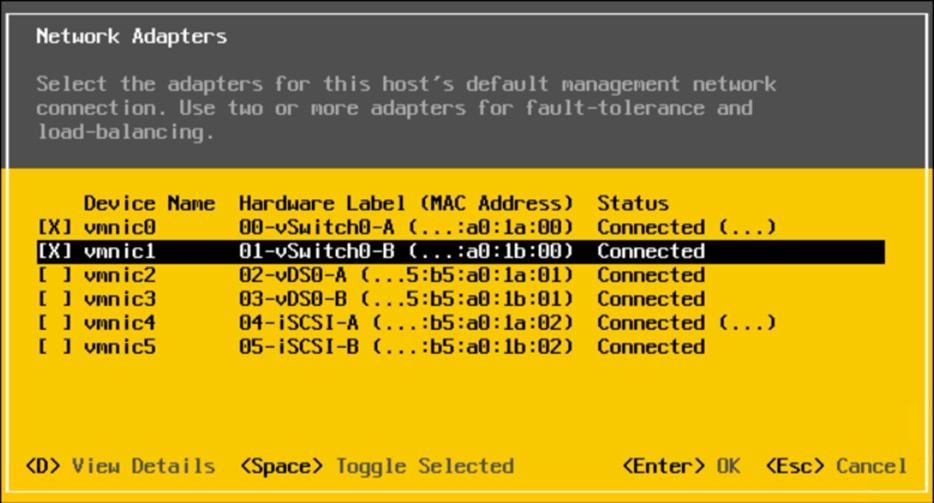
![]() In lab testing, examples have been seen where the vmnic and device ordering do not match. If this is the case, use the Consistent Device Naming (CDN) to note which vmnics are mapped to which vNICs and adjust the upcoming procedure accordingly.
In lab testing, examples have been seen where the vmnic and device ordering do not match. If this is the case, use the Consistent Device Naming (CDN) to note which vmnics are mapped to which vNICs and adjust the upcoming procedure accordingly.
11. Press Enter.
12. Choose the VLAN (Optional) option and press Enter.
13. Enter the <ib-mgmt-vlan-id> and press Enter.
14. Choose IPv4 Configuration and press Enter.
15. Choose the “Set static IPv4 address and network configuration” option by using the arrow keys and space bar.
16. Move to the IPv4 Address field and enter the IP address for managing the ESXi host.
17. Move to the Subnet Mask field and enter the subnet mask for the ESXi host.
18. Move to the Default Gateway field and enter the default gateway for the ESXi host.
19. Press Enter to accept the changes to the IP configuration.
20. Choose the IPv6 Configuration option and press Enter.
21. Using the spacebar, choose Disable IPv6 (restart required) and press Enter.
22. Choose the DNS Configuration option and press Enter.
![]() Because the IP address is assigned manually, the DNS information must also be entered manually.
Because the IP address is assigned manually, the DNS information must also be entered manually.
23. Using the spacebar, choose “Use the following DNS server addresses and hostname:”
24. Move to the Primary DNS Server field and enter the IP address of the primary DNS server.
25. Optional: Move to the Alternate DNS Server field and enter the IP address of the secondary DNS server.
26. Move to the Hostname field and enter the fully qualified domain name (FQDN) for the ESXi host.
27. Press Enter to accept the changes to the DNS configuration.
28. Press Esc to exit the Configure Management Network submenu.
29. Press Y to confirm the changes and reboot the ESXi host.
Reset VMware ESXi Host VMkernel Port vmk0 MAC Address (Optional)
All ESXi Hosts
By default, the MAC address of the management VMkernel port vmk0 is the same as the MAC address of the Ethernet port it is placed on. If the ESXi host’s boot LUN is remapped to a different server with different MAC addresses, a MAC address conflict will exist because vmk0 will retain the assigned MAC address unless the ESXi System Configuration is reset. To reset the MAC address of vmk0 to a random VMware-assigned MAC address, follow these steps:
1. From the ESXi console menu main screen, type Ctrl-Alt-F1 to access the VMware console command line interface. In the UCSM KVM, Ctrl-Alt-F1 appears in the list of Static Macros.
2. Log in as root.
3. Type esxcfg-vmknic –l to get a detailed listing of interface vmk0. vmk0 should be a part of the “Management Network” port group. Note the IP address and netmask of vmk0.
4. To remove vmk0, type esxcfg-vmknic –d “Management Network”.
5. To re-add vmk0 with a random MAC address, type esxcfg-vmknic –a –i <vmk0-ip> -n <vmk0-netmask> “Management Network”.
6. Verify vmk0 has been re-added with a random MAC address by typing esxcfg-vmknic –l.
7. Tag vmk0 as the management interface by typing esxcli network ip interface tag add -i vmk0 -t Management.
8. When vmk0 was re-added, if a message popped up saying vmk1 was marked as the management interface, type esxcli network ip interface tag remove -i vmk1 -t Management.
9. Type exit to log out of the command line interface.
10. Type Ctrl-Alt-F2 to return to the ESXi console menu interface.
Install VMware and Cisco VIC Drivers for the ESXi Host
Download the offline bundle for the UCS Tools Component and the NetApp NFS Plug-in for VMware VAAI to the Management workstation:
UCS Tools Component for ESXi 7.0 1.1.5 (ucs-tool-esxi_1.1.5-1OEM.zip)
NetApp NFS Plug-in 1.1.2-3 for VMware VAAI (ucs-tool-esxi_1.1.2-1OEM.zip)
All ESXi Hosts
To install VMware VIC Drivers and the NetApp NFS Plug-in for VMware VAAI on the ESXi host VM-Host-Infra-01 and VM-Host-Infra-02, follow these steps:
1. Using an SCP program such as WinSCP, copy the two offline bundles referenced above to the /tmp directory on each ESXi host.
2. Using a SSH tool such as PuTTY, ssh to each VMware ESXi host. Log in as root with the root password.
3. Type cd /tmp.
4. Run the following commands on each host:
esxcli software component apply -d /tmp/ucs-tool-esxi_1.1.5-1OEM.zip
esxcli software vib install -d /tmp/NetAppNasPlugin.v23.zip
reboot
esxcli software component list | grep ucs
esxcli software vib list | grep NetApp
Log into the First VMware ESXi Host by Using VMware Host Client
The process for the first VMware host will be setup directly using the ESXi vSphere Web Client for that host. Subsequent hosts will be added to vCenter and configured with slightly differing steps through the vCenter client.
ESXi Host VM-Host-Infra-01
To log into the VM-Host-Infra-01 ESXi host by using the VMware Host Client, follow these steps:
1. Open a web browser on the management workstation and navigate to the VM-Host-Infra-01 management IP address.
2. Enter root for the User name.
3. Enter the root password.
4. Click Login to connect.
5. Decide whether to join the VMware Customer Experience Improvement Program and click OK.
Set Up VMkernel Ports and Virtual Switch
ESXi Host VM-Host-Infra-01
To set up the VMkernel ports and the virtual switches on the first ESXi host, follow these steps:
![]() In this procedure, you’re only setting up the first ESXi host. The second and third hosts will be added to vCenter and setup from the vCenter HTML5 Interface.
In this procedure, you’re only setting up the first ESXi host. The second and third hosts will be added to vCenter and setup from the vCenter HTML5 Interface.
![]() In these steps, the vMotion VMkernel will not be created as it will later be setup on the vDS after vCenter is in place. If vMotion is not going to be handled within the vDS and has been set to be in vSwitch0 by the vNIC templates created during the UCS setup, the required portgroup and VMkernel should be created in this section.
In these steps, the vMotion VMkernel will not be created as it will later be setup on the vDS after vCenter is in place. If vMotion is not going to be handled within the vDS and has been set to be in vSwitch0 by the vNIC templates created during the UCS setup, the required portgroup and VMkernel should be created in this section.
1. From the Host Client Navigator, choose Networking.
2. In the center pane, choose the Virtual switches tab.
3. Highlight the vSwitch0 line.
4. Choose Edit settings.
5. Change the MTU to 9000.
6. Expand NIC teaming.
7. In the Failover order section, choose vmnic1 and click Mark active.
8. Verify that vmnic1 now has a status of Active.
9. Click Save.
10. Choose Networking, then choose the Port groups tab.
11. In the center pane, right-click VM Network and choose Edit settings.
12. Name the port group Site1-IB Network and enter <site1-ib-vlan-id> in the VLAN ID field.
13. Click Save to finalize the edits for the Site1-IB Network.
14. Still within the Port groups tab select the Add port group option to create a Common-Services port group that will be used for vCenter and other virtual infrastructure components.
15. Specify the name and VLAN ID.
16. Click Add to create the port group.
17. At the top, choose the VMkernel NICs tab.
18. Click Add VMkernel NIC.
19. For New port group, enter VMkernel-Infra-NFS.
20. For Virtual switch, choose vSwitch0.
21. Enter <infra-nfs-vlan-id> for the VLAN ID.
22. Change the MTU to 9000.
23. Choose Static IPv4 settings and expand IPv4 settings.
24. Enter the ESXi host Infrastructure NFS IP address and netmask.
25. Leave TCP/IP stack set at Default TCP/IP stack and do not choose any of the Services.
26. Click Create.
27. Choose the Virtual Switches tab, then vSwitch0. The properties for vSwitch0 VMkernel NICs should be similar to the following example:
28. In the center pane, choose the Virtual switches tab.
29. Highlight the iScsiBootvSwitch line.
30. Choose Edit settings.
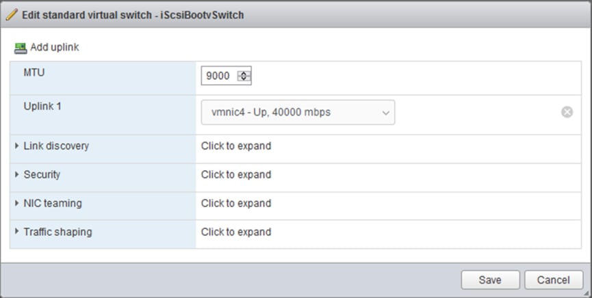
32. Click Save to save the changes to iScsiBootvSwitch.
33. Choose Add standard virtual switch.
34. Name the switch vSwitch1.
35. Change the MTU to 9000.
36. From the drop-down list select vmnic5 for Uplink 1.
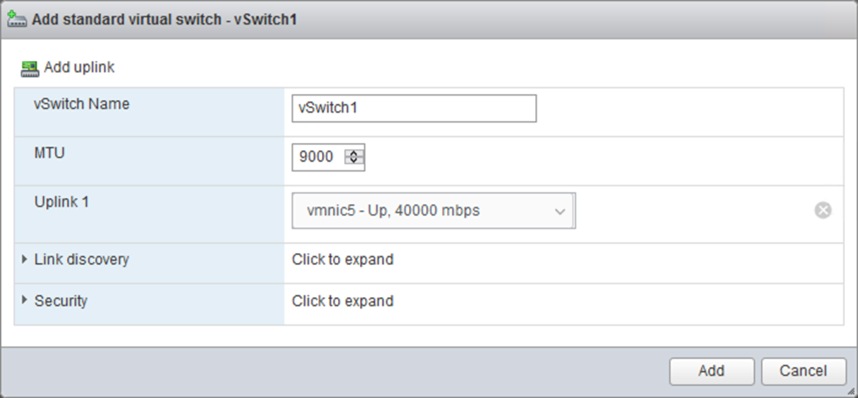
37. Choose Add to add vSwitch1.
38. In the center pane, choose the VMkernel NICs tab.
39. Highlight the iScsiBootPG line.
40. Choose Edit settings.
41. Change the MTU to 9000.
42. Expand IPv4 Settings and enter a unique IP address in the Infra-iSCSI-A subnet but outside of the Cisco UCS iSCSI-IP-Pool-A.
![]() It is recommended to enter a unique IP address for this VMkernel port to avoid any issues related to IP Pool reassignments in Cisco UCS.
It is recommended to enter a unique IP address for this VMkernel port to avoid any issues related to IP Pool reassignments in Cisco UCS.
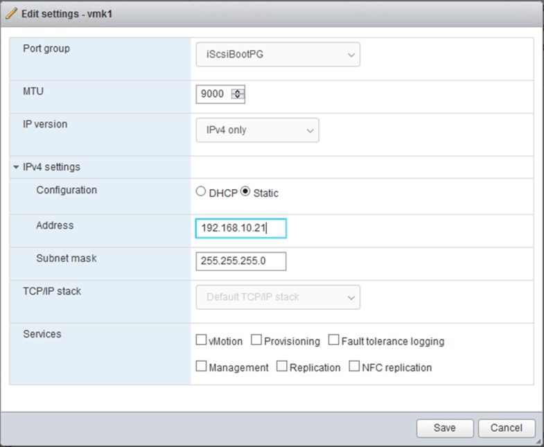
43. Click Save to save the changes to iScsiBootPG VMkernel NIC.
44. Choose Add VMkernel NIC.
45. For New port group, enter iScsiBootPG-B.
46. For Virtual switch, use the pull-down to choose vSwitch1.
47. Change the MTU to 9000.
48. For IPv4 settings, choose Static.
49. Expand IPv4 Settings and enter a unique IP address in the Infra-iSCSI-B subnet but outside of the Cisco UCS iSCSI-IP-Pool-B.
50. Click Create to complete creating the VMkernel NIC.
51. In the center pane, choose the Port groups tab.
52. Highlight the iScsiBootPG line.
53. Choose Edit settings.
54. Change the Name to iScsiBootPG-A.
55. Click Save to complete editing the port group name.
56. Choose Networking and the VMkernel NICs tab to confirm configured virtual adapters. The adapters listed should be similar to the following example:
ESXi Host VM-Host-Infra-01
To mount the required datastores, follow these steps on the first ESXi host:
1. From the Host Client, choose Storage.
2. In the center pane, choose the Datastores tab.
3. In the center pane, choose New Datastore to add a new datastore.
4. In the New datastore popup, choose Mount NFS datastore and click Next.
5. Input infra_datastore_1 for the datastore name. Input the IP address for the nfs-lif-01 LIF for the NFS server. Input /infra_datastore_1 for the NFS share. Leave the NFS version set at NFS 3. Click Next.
6. Click Finish. The datastore should now appear in the datastore list.
7. In the center pane, choose New Datastore to add a new datastore.
8. In the New datastore popup, choose Mount NFS datastore and click Next.
9. Input infra_swap for the datastore name. Input the IP address for the nfs-lif-01 LIF for the NFS server. Input /infra_swap for the NFS share. Leave the NFS version set at NFS 3. Click Next.
10. Click Finish. The datastore should now appear in the datastore list.
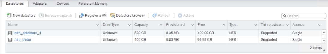
Configure NTP on First ESXi Host
ESXi Host VM-Host-Infra-01
To configure Network Time Protocol (NTP) on the first ESXi host, follow these steps:
1. From the Host Client, choose Manage.
2. In the center pane, choose System > Time & Date.
3. Click Edit NTP settings.
4. Make sure “Manually configure the date and time on this host and enter the approximate date and time.
5. Select Use Network Time Protocol (enable NTP client).
6. Use the drop-down list to choose Start and stop with host.
7. Enter the two Nexus switch NTP addresses in the NTP server(s) box separated by a comma.
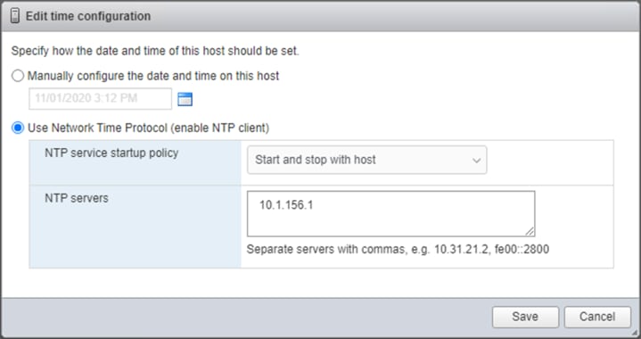
8. Click Save to save the configuration changes.
![]() It currently is not possible to start NTP from the ESXi Host Client. NTP will be started from vCenter. The NTP server time may vary slightly from the host time.
It currently is not possible to start NTP from the ESXi Host Client. NTP will be started from vCenter. The NTP server time may vary slightly from the host time.
ESXi Host VM-Host-Infra-01
To configure host swap on the first ESXi host, follow these steps on the host:
1. From the Host Client, choose Manage.
2. In the center pane, choose System > Swap.
3. Click Edit settings.
4. Use the drop-down list to choose infra_swap. Leave all other settings unchanged.
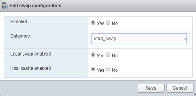
5. Click Save to save the configuration changes.
Configure Host Power Policy
ESXi Host VM-Host-Infra-01
To configure the host power policy on the first ESXi host, follow these steps on the host:
1. From the Host Client, choose Manage.
2. In the center pane, choose Hardware > Power Management.
3. Choose Change policy.
4. Choose High performance and click OK.
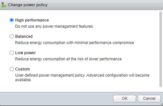
VMware vCenter 7.0d
The procedures in the following subsections provide detailed instructions for installing the VMware vCenter 7.0d Server Appliance in a FlexPod environment. After the procedures are completed, a VMware vCenter Server will be configured.
Build the VMware vCenter Server Appliance
The VCSA deployment consists of 2 stages: install and configuration. To build the VMware vCenter virtual machine, follow these steps:
1. Locate and copy the VMware-VCSA-all-7.0.0-16749653.iso file to the desktop of the management workstation. This ISO is for the VMware vSphere 7.0 vCenter Server Appliance.
![]() It is important to use at minimum VMware vCenter release 7.0b to ensure access to all needed features.
It is important to use at minimum VMware vCenter release 7.0b to ensure access to all needed features.
2. Using ISO mounting software, mount the ISO image as a disk on the management workstation. (For example, with the Mount command in Windows Server 2012 and above).
3. In the mounted disk directory, navigate to the vcsa-ui-installer > win32 directory and double-click installer.exe. The vCenter Server Appliance Installer wizard appears.
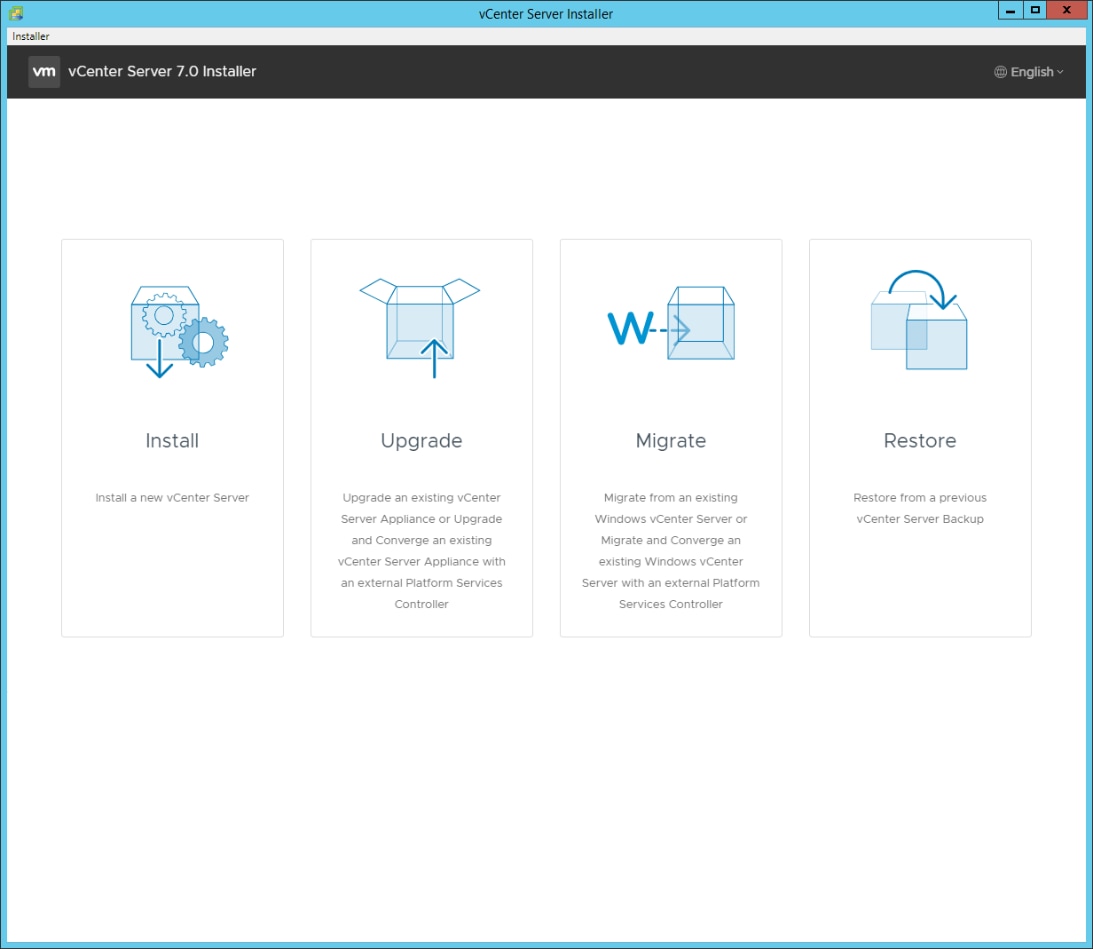
4. Click Install to start the vCenter Server Appliance deployment wizard.
5. Click NEXT in the Introduction section.
6. Read and accept the license agreement and click NEXT.
7. In the “vCenter Server deployment target” window, enter the host name or IP address of the first ESXi host, User name (root) and Password. Click NEXT.
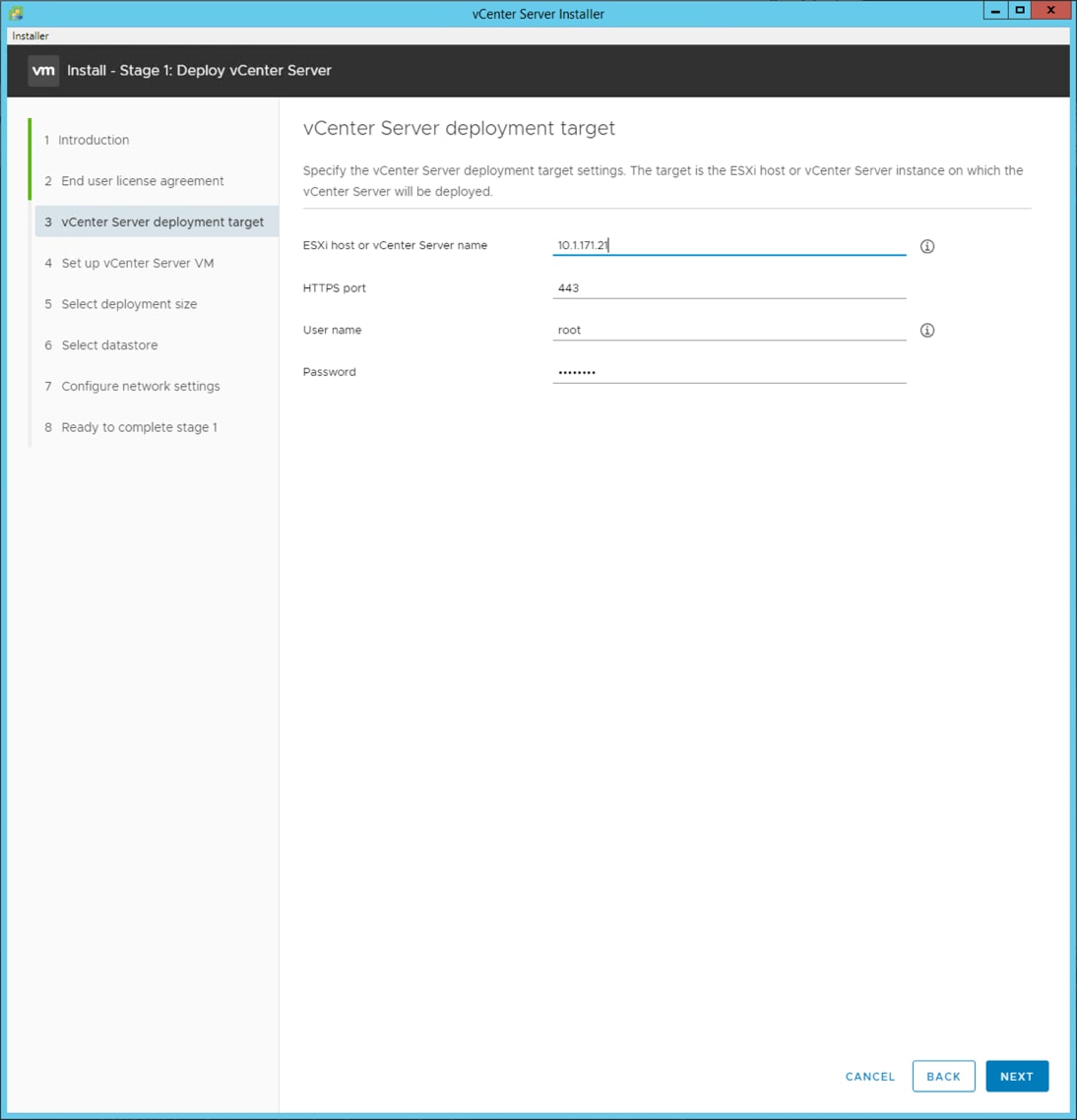
8. Click YES to accept the certificate.
9. Enter the Appliance VM name and password details in the “Set up vCenter Server VM” section. Click NEXT.
10. In the “Select deployment size” section, choose the Deployment size and Storage size. For example, choose “Small” and “Default”. Click NEXT.
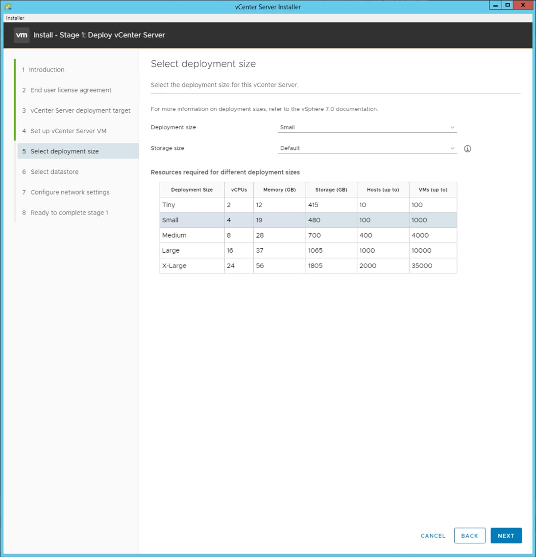
11. Choose infra_datastore_1 for storage. Click NEXT.
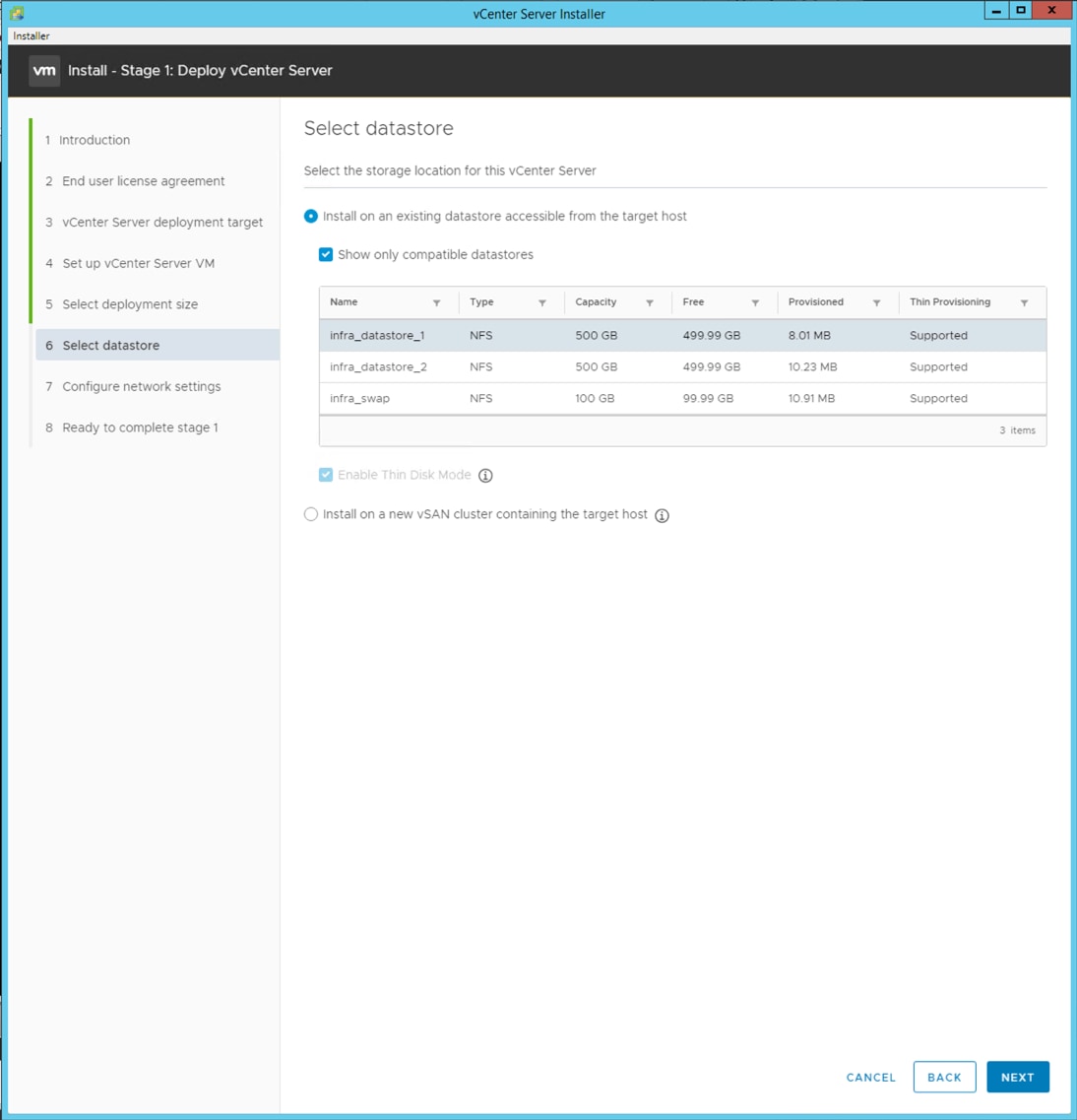
12. In the “Network Settings” section, configure the below settings:
a. Choose a Network: Common-Services Network.
![]() It is important that the vCenter VM stay on the Common-Services Network on vSwitch0 and that it not get moved to a vDS. If vCenter is moved to a vDS and the virtual environment is completely shut down and then brought back up, and it is attempted to bring up vCenter on a different host than the one it was running on before the shutdown, vCenter will not have a functional network connection. With the vDS, for a virtual machine to move from one host to another, vCenter must be up and running to coordinate the move of the virtual ports on the vDS. If vCenter is down, the port move on the vDS cannot occur correctly. Moving vCenter to a different host on vSwitch0 to be brought up always occurs correctly without requiring vCenter to already be up and running.
It is important that the vCenter VM stay on the Common-Services Network on vSwitch0 and that it not get moved to a vDS. If vCenter is moved to a vDS and the virtual environment is completely shut down and then brought back up, and it is attempted to bring up vCenter on a different host than the one it was running on before the shutdown, vCenter will not have a functional network connection. With the vDS, for a virtual machine to move from one host to another, vCenter must be up and running to coordinate the move of the virtual ports on the vDS. If vCenter is down, the port move on the vDS cannot occur correctly. Moving vCenter to a different host on vSwitch0 to be brought up always occurs correctly without requiring vCenter to already be up and running.
b. IP version: IPV4
c. IP assignment: static
d. FQDN: <vcenter-fqdn>
e. IP address: <vcenter-ip>
f. Subnet mask or prefix length: <vcenter-subnet-mask>
g. Default gateway: <vcenter-gateway>
h. DNS Servers: <dns-server>
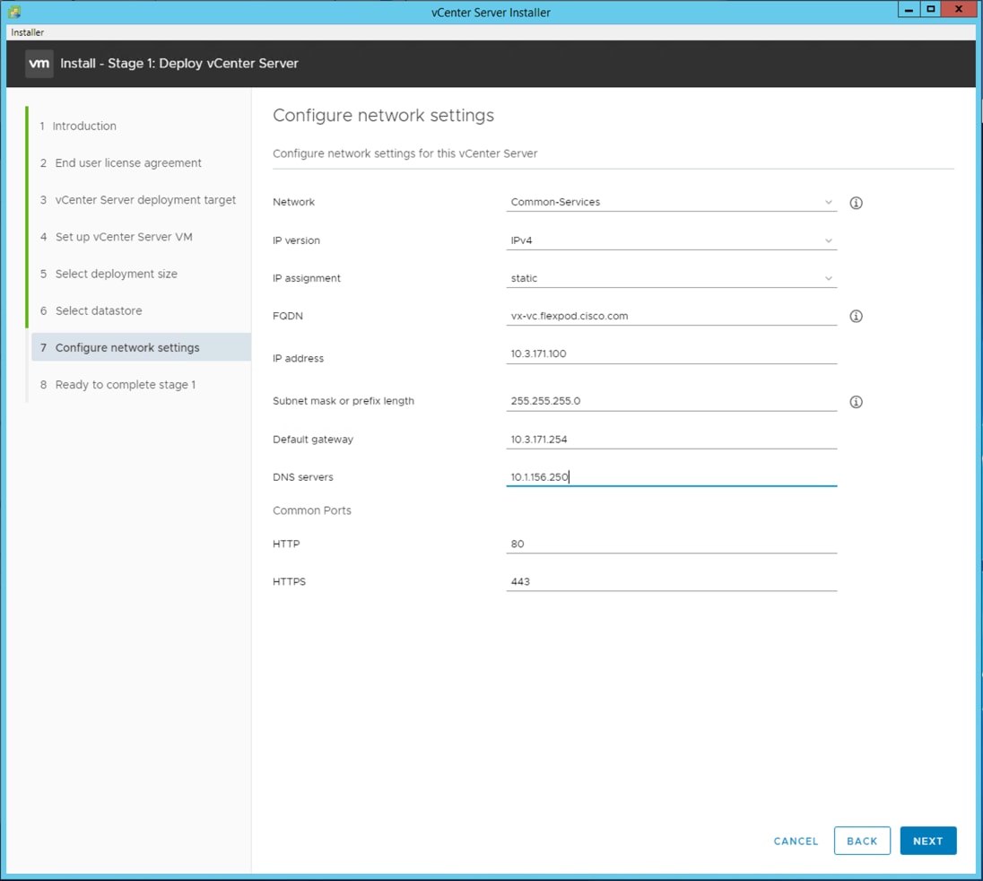
13. Click NEXT.
14. Review all values and click FINISH to complete the installation.
![]() The vCenter Server appliance installation will take a few minutes to complete.
The vCenter Server appliance installation will take a few minutes to complete.
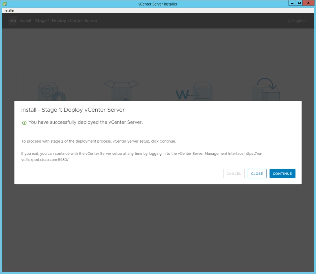
15. Click CONTINUE to proceed with stage 2 configuration.
16. Click NEXT.
17. In the vCenter Server configuration window, configure these settings:
a. Time Synchronization Mode: Synchronize time with NTP servers.
b. NTP Servers: <ntp-server>
c. SSH access: Enabled.
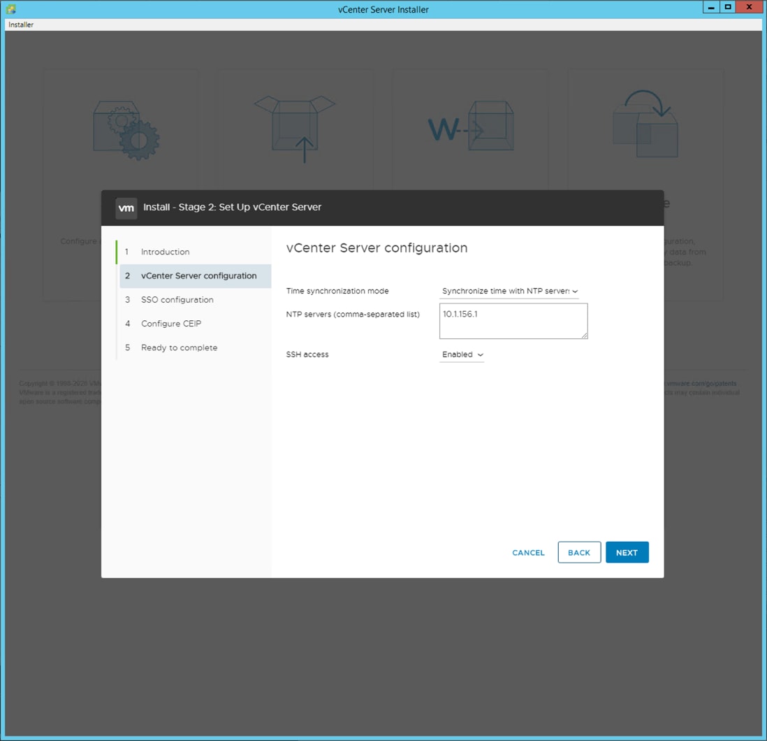
18. Click NEXT.
19. Complete the SSO configuration as shown below, or according to your organization’s security policies:
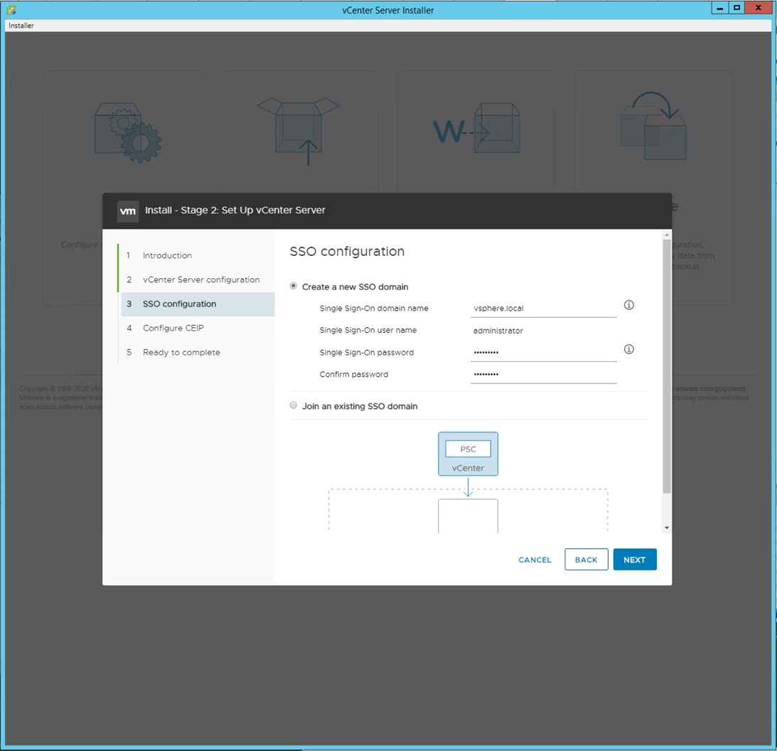
20. Click NEXT.
21. Decide whether to join VMware’s Customer Experience Improvement Program (CEIP).
22. Click NEXT.
23. Review the configuration and click FINISH.
24. Click OK.
![]() vCenter Server setup will take a few minutes to complete.
vCenter Server setup will take a few minutes to complete.
25. Click CLOSE. Eject or unmount the VCSA installer ISO.
If a vCenter deployment size of Small or larger was selected in the vCenter setup, it is possible that the VCSA’s CPU setup does not match the Cisco UCS server CPU hardware configuration. Cisco UCS B and C-Series servers are normally 2-socket servers. In this validation, the Small deployment size was selected and vCenter was setup for a 4-socket server. This setup will cause issues in the VMware ESXi cluster Admission Control. To resolve the Admission Control issue, follow these steps:
1. Open a web browser on the management workstation and navigate to the VM-Host-Infra-01 management IP address.
2. Enter root for the user name.
3. Enter the root password.
4. Click Login to connect.
5. On the left, choose Virtual Machines.
6. In the center pane, right-click the vCenter VM and choose Edit.
7. In the Edit settings window, expand CPU and check the value of Sockets.
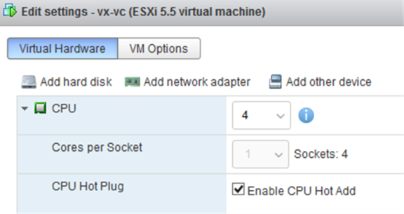
8. If the number of Sockets does not match your server configuration, it will need to be adjusted. Click Cancel.
9. If the number of Sockets needs to be adjusted:
a. Right-click the vCenter VM and choose Guest OS > Shut down. Click Yes on the confirmation.
b. Once vCenter is shut down, right-click the vCenter VM and choose Edit settings.
c. In the Edit settings window, expand CPU and change the Cores per Socket value to make the Sockets value equal to your server configuration (usually 2).
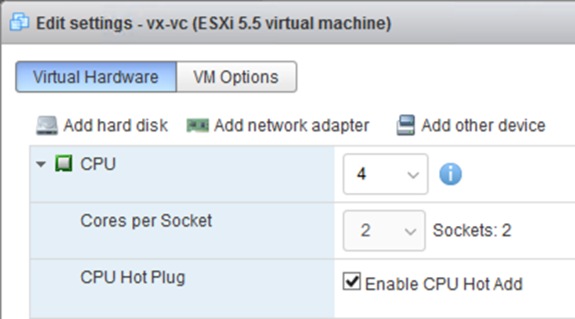
d. Click Save.
e. Right-click the vCenter VM and choose Power > Power on. Wait approximately 10 minutes for vCenter to come up.
To setup the VMware vCenter Server, follow these steps:
1. Using a web browser, navigate to https://<vcenter-ip-address>:5480. You will need to navigate security screens.
2. Log into the VMware vCenter Server Management interface as root with the root password set in the vCenter installation.
3. In the menu on the left, choose Time.
4. Choose EDIT to the right of Time zone.
5. Choose the appropriate Time zone and click SAVE.
6. In the menu on the left choose Administration.
7. According to your Security Policy, adjust the settings for the root user and password.
8. In the menu on the left choose Update.
9. Follow the prompts to STAGE AND INSTALL any available vCenter updates. In this validation, vCenter version 7.0.0.10700 was installed and did not require any updates at the time of installation.
10. In the upper right-hand corner of the screen, choose root > Logout to logout of the Appliance Management interface.
11. Using a web browser, navigate to https://<vcenter-fqdn>. You will need to navigate security screens.
![]() With VMware vCenter 7.0, the use of the vCenter FQDN is required.
With VMware vCenter 7.0, the use of the vCenter FQDN is required.
12. Choose LAUNCH VSPHERE CLIENT (HTML5).
![]() Although the previous versions of this document used the FLEX vSphere Web Client, the VMware vSphere HTML5 Client is the only option in vSphere 7 and will be used going forward.
Although the previous versions of this document used the FLEX vSphere Web Client, the VMware vSphere HTML5 Client is the only option in vSphere 7 and will be used going forward.
13. Log in using the Single Sign-On username (administrator@vsphere.local) and password created during the vCenter installation. Dismiss the Licensing warning at this time.
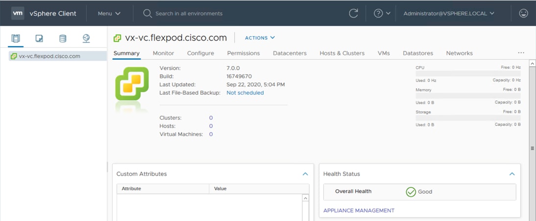
14. In the center pane, choose ACTIONS > New Datacenter.
15. Type “FlexPod-DC” in the Datacenter name field.
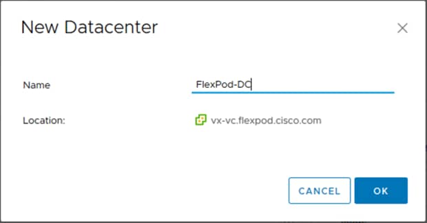
16. Click OK.
17. Expand the vCenter on the left.
18. Right-click the datacenter FlexPod-DC in the list in the left pane. Choose New Cluster.
19. Name the cluster FlexPod-Management.
20. Turn on DRS and vSphere HA. Do not turn on vSAN.
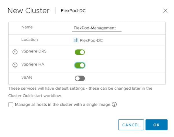
21. Click OK to create the new cluster.
22. Right-click “FlexPod-Management” and choose Settings.
23. Choose Configuration > General in the list located on the left and choose EDIT located on the right of General.
24. Choose Datastore specified by host and click OK.
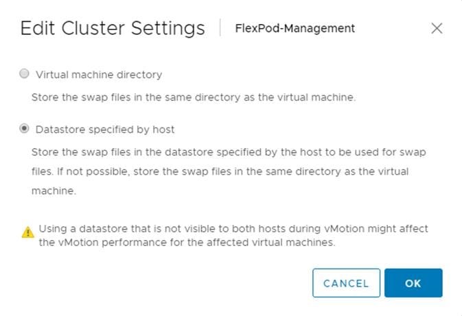
25. Right-click “FlexPod-Management” and click Add Hosts.
26. In the IP address or FQDN field, enter either the IP address or the FQDN of the first VMware ESXi host. Enter root as the Username and the root password. Click NEXT.
27. In the Security Alert window, choose the host and click OK.
28. Verify the Host summary information and click NEXT.
29. Ignore warnings about the host being moved to Maintenance Mode if they appear and click FINISH to complete adding the host to the cluster.
30. The added ESXi host will have Warnings that the ESXi Shell and SSH have been enabled. These warnings can be suppressed.
31. In the list, right-click the added ESXi host and choose Settings.
32. In the left pane of the host under Virtual Machines, choose Swap File location.
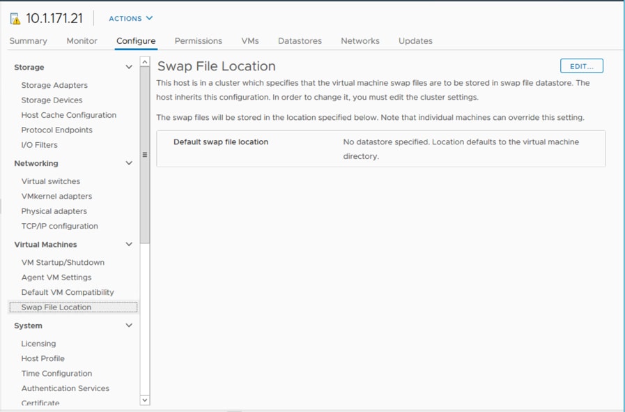
33. Click EDIT.
34. Choose the infra_swap datastore and click OK.
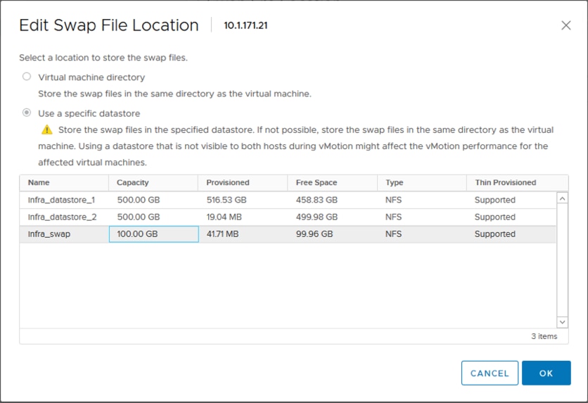
35. In the list under System, choose Time Configuration.
36. Click EDIT to the right of Manual Time Configuration. Set the time and date to the correct local time and click OK.
37. Click EDIT to the right of Network Time Protocol.
38. In the Edit Network Time Protocol window, select Enable and then select Start NTP Service. Ensure the other fields are filled in correctly and click OK.
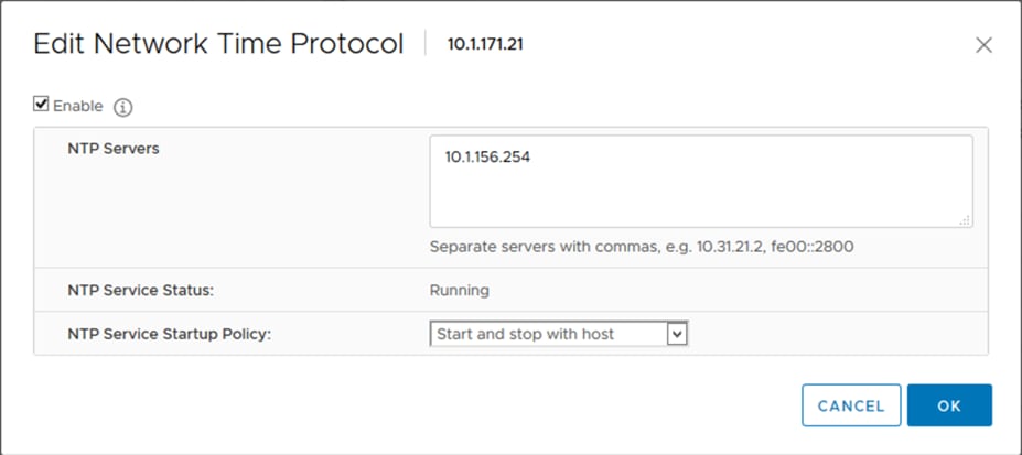
39. In the list under Hardware, choose Overview. Scroll to the bottom and ensure the Power Management Active policy is High Performance. If the Power Management Active policy is not High Performance, to the right of Power Management, choose EDIT POWER POLICY. Choose High performance and click OK.
40. In the list under Storage, choose Storage Devices. Make sure the NETAPP Fibre Channel Disk LUN 0 or NETAPP iSCSI Disk LUN 0 is selected.
41. Choose the Paths tab.
42. Ensure that 4 paths appear, two of which should have the status Active (I/O).
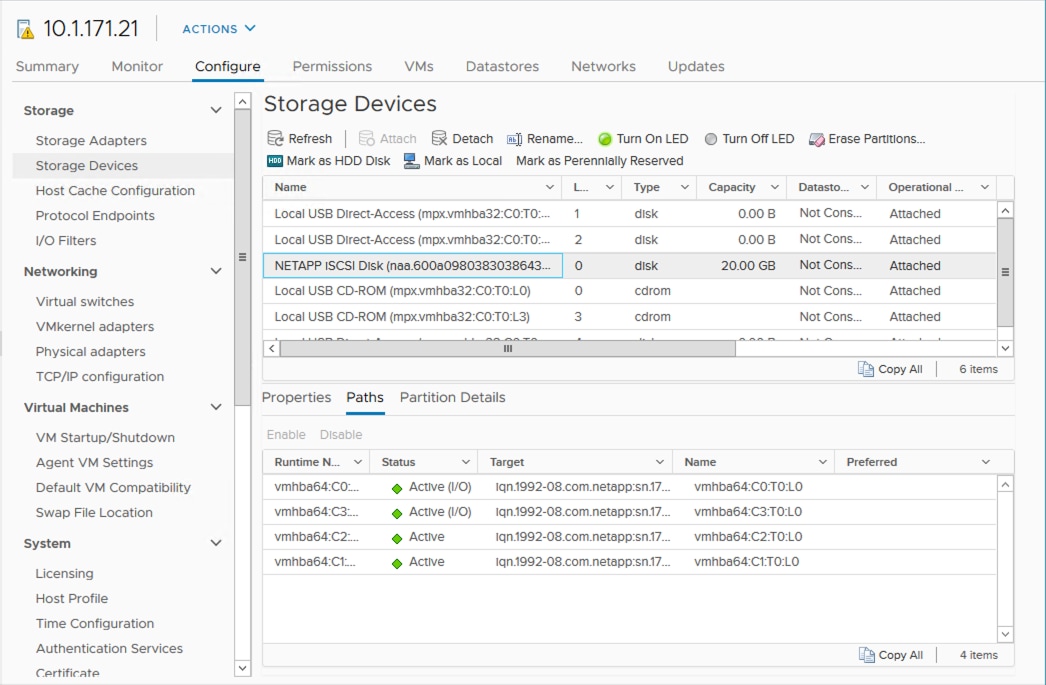
Add AD User Authentication to vCenter (Optional)
If an AD Infrastructure is set up in this FlexPod environment, you can setup in AD and authenticate from vCenter.
To add an AD user authentication to the vCenter, follow these steps:
1. In the AD Infrastructure, using the Active Directory Users and Computers tool, setup a Domain Administrator user with a user name such as flexadmin (FlexPod Admin).
2. Connect to https://<vcenter-ip> and choose LAUNCH VSPHERE CLIENT (HTML5).
3. Log in as Administrator@vsphere.local (or the SSO user set up in vCenter installation) with the corresponding password.
4. Under Menu, choose Administration. In the list on the left, under Single Sign On, choose Configuration.
5. In the center pane, under Configuration, choose the Identity Provider tab.
6. In the list under Type, select Active Directory Domain.
7. Choose JOIN AD.
8. Fill in the AD domain name, the Administrator user, and the domain Administrator password. Do not fill in an Organizational unit. Click JOIN.
9. Click Acknowledge.
10. In the list on the left under Deployment, choose System Configuration. Choose the radio button to choose the vCenter, then choose REBOOT NODE.
11. Input a reboot reason and click OK. The reboot will take approximately 10 minutes for full vCenter initialization.
12. Log back into the vCenter vSphere HTML5 Client as Administrator@vsphere.local.
13. Under Menu, choose Administration. In the list on the left, under Single Sign On, choose Configuration.
14. In the center pane, under Configuration, choose the Identity Provider tab. Under Type, select Identity Sources. Click ADD.
15. Make sure your Active Directory (Integrated Windows Authentication) is selected, your Windows Domain name is listed, and Use machine account is selected. Click ADD.
16. In the list select the Active Directory (Integrated Windows Authentication) Identity source type. If desired, select SET AS DEFAULT and click OK.
17. On the left under Access Control, choose Global Permissions.
18. In the center pane, click the + sign to add a Global Permission.
19. In the Add Permission window, choose your AD domain for the Domain.
20. On the User/Group line, enter either the FlexPod Admin username or the Domain Admins group. Leave the Role set to Administrator. Choose the Propagate to children checkbox.
![]() The FlexPod Admin user was created in the Domain Admins group. The selection here depends on whether the FlexPod Admin user will be the only user used in this FlexPod or you would like to add other users later. By selecting the Domain Admins group, any user placed in that group in the AD domain will be able to login to vCenter as an Administrator.
The FlexPod Admin user was created in the Domain Admins group. The selection here depends on whether the FlexPod Admin user will be the only user used in this FlexPod or you would like to add other users later. By selecting the Domain Admins group, any user placed in that group in the AD domain will be able to login to vCenter as an Administrator.
21. Click OK to add the selected User or Group. The user or group should now appear in the Global Permissions list with the Administrator role.
22. Log out and log back into the vCenter HTML5 Client as the FlexPod Admin user. You will need to add the domain name to the user, for example, flexadmin@domain.
FlexPod VMware vSphere Distributed Switch (vDS)
This section provides detailed procedures for installing the VMware vDS in vCenter and on the first FlexPod ESXi Management Host.
In section Cisco UCS Setup, two sets of vNICs were configured. The vmnic ports associated with the vDS0-A and B vNICs will be placed on the VMware vDS in this procedure. The vMotion VMkernel port(s) will be placed on the vDS.
A vMotion, and a VM-Traffic port group will be added to the vDS. Any additional VLAN-based port groups added to the vDS would need to have the corresponding VLANs added to the Cisco UCS LAN cloud, to the Cisco UCS vDS0-A and B vNIC templates, and to the Cisco Nexus 9K switches and vPC peer-link interfaces on the switches.
In this document, the infrastructure ESXi management VMkernel ports, the In-Band management interfaces including the vCenter management interface, and the infrastructure NFS VMkernel ports are left on vSwitch0 to facilitate bringing the virtual environment back up in the event it needs to be completely shut down. When the vMotion port group is created, it is pinned to Cisco UCS fabric B to reduce the need for vMotion traffic leaving the fabric interconnect. Pinning should be done in a vDS to ensure consistency across all ESXi hosts.
Configure the VMware vDS in vCenter
VMware vSphere Web Client
To configure the vDS, follow these steps:
1. After logging into the VMware vSphere HTML5 Client, choose Networking under Menu.
2. Right-click the FlexPod-DC datacenter and choose Distributed Switch > New Distributed Switch.
3. Give the Distributed Switch a descriptive name (vDS0) and click NEXT.
4. Make sure version 7.0.0 – ESXi 7.0 and later is selected and click NEXT.
5. Change the Number of uplinks to 2. If VMware Network I/O Control is to be used for Quality of Service, leave Network I/O Control Enabled. Otherwise, Disable Network I/O Control. Enter VM-Traffic-1 for the Port group name. Click NEXT.
6. Review the information and click FINISH to complete creating the vDS.
7. Expand the FlexPod-DC datacenter and the newly created vDS. Choose the newly created vDS.
8. Right-click the VM-Traffic-1 port group and choose Edit Settings.
9. Choose VLAN on the left.
10. Choose VLAN for VLAN type and enter the VM-Traffic-1 VLAN ID. Click OK.
11. Right-click the vDS and choose Settings > Edit Settings.
12. In the Edit Settings window, choose Advanced on the left.
13. Change the MTU to 9000. The Discovery Protocol can optionally be changed to Link Layer Discovery Protocol and the Operation to Both. Click OK.
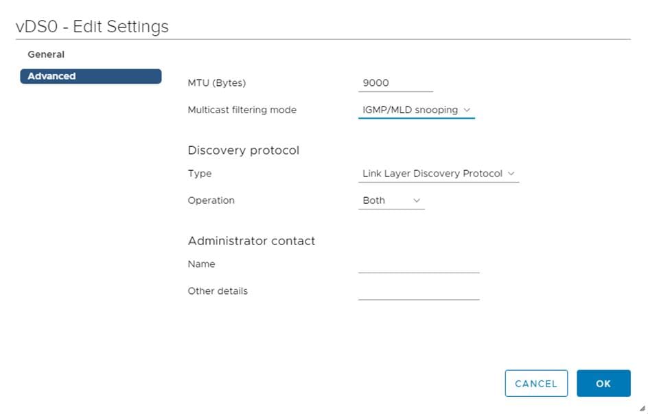
14. For the vMotion port group, right-click the vDS, choose Distributed Port Group, and choose New Distributed Port Group.
15. Enter vMotion as the name and click NEXT.
16. Set the VLAN type to VLAN, enter the VLAN ID used for vMotion, click the Customize default policies configuration check box, and click NEXT.
17. Leave the Security options set to Reject and click NEXT.
18. Leave the Ingress and Egress traffic shaping options as Disabled and click NEXT.
19. Choose Uplink 1 from the list of Active uplinks and click the down arrow icon twice to place Uplink 1 in the list of Standby uplinks. This will pin all vMotion traffic to Cisco UCS Fabric Interconnect B except when a failure occurs.
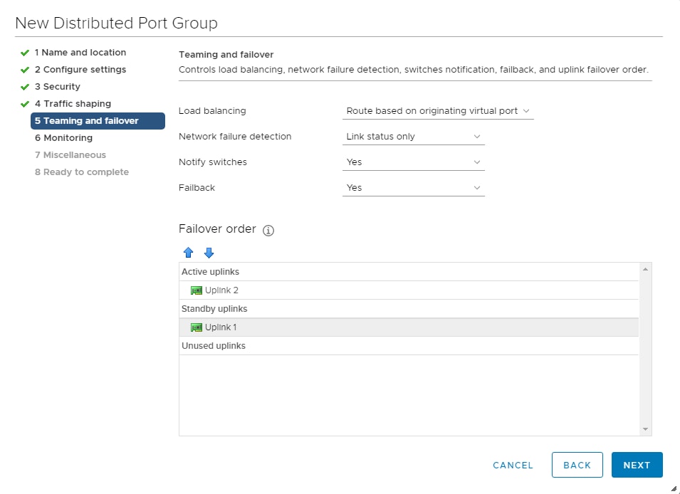
20. Click NEXT.
21. Leave NetFlow disabled and click NEXT.
22. Leave Block all ports set as No and click NEXT.
23. Confirm the options and click FINISH to create the port group.
24. Repeat the addition of new distributed port groups for any additional application port groups, setting the active links as appropriate.
25. Right-click the vDS and choose Add and Manage Hosts.
26. Make sure Add hosts is selected and click NEXT.
27. Click the green + sign to add New hosts. Choose the one configured FlexPod Management host and click OK. Click NEXT.
28. Choose vmnic2 and click Assign uplink. Choose Uplink 1 and click OK. Choose vmnic3 and click Assign uplink. Choose Uplink 2 and click OK.
![]() It is important to assign the uplinks as shown below. This allows the port groups to be pinned to the appropriate Cisco UCS fabric.
It is important to assign the uplinks as shown below. This allows the port groups to be pinned to the appropriate Cisco UCS fabric.
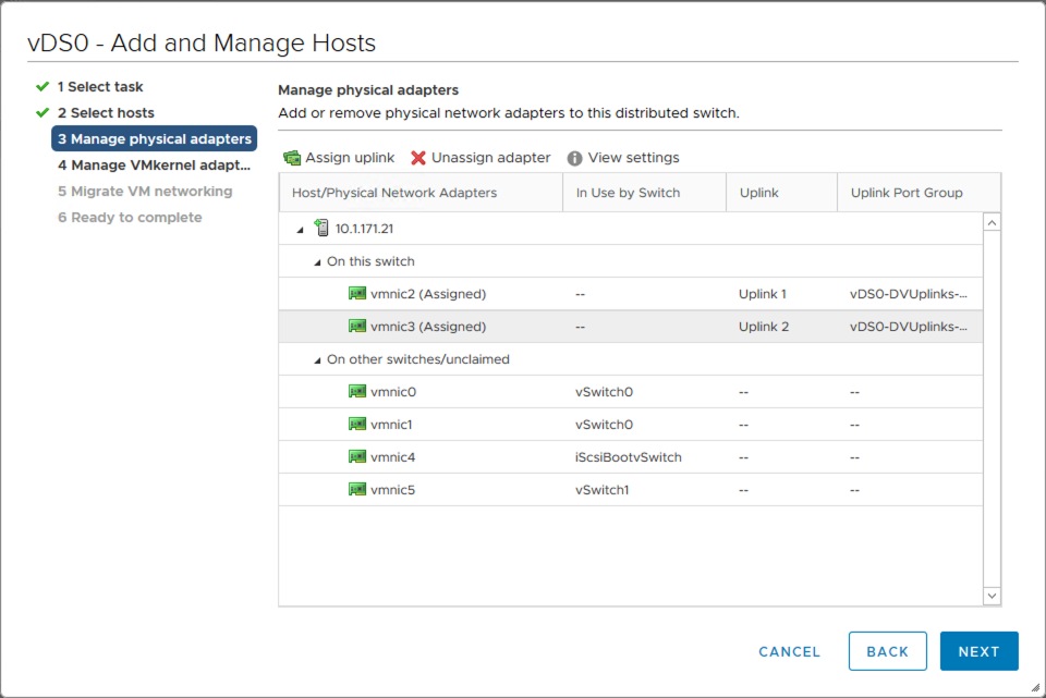
29. Click NEXT.
30. Do not migrate any VMkernel ports and click NEXT.
31. Do not migrate any virtual machine networking ports. Click NEXT.
32. Click FINISH to complete adding the ESXi host to the vDS.
Add and Configure a VMware ESXi Host in vCenter
This section details the steps to add and configure an ESXi host in vCenter. This section assumes the host has had VMware ESXi 7.0b installed, the management IP address set, and the Cisco UCS Tool and NetApp NFS Plug-in for VMware VAAI installed. This procedure is initially being run on the second and third ESXi management hosts but can be run on any added ESXi host.
ESXi Hosts created other than VM-Host-Infra-01
To add the ESXi host(s) to vCenter, follow these steps:
1. From the Home screen in the VMware vCenter HTML5 Interface, choose Menu > Hosts and Clusters.
2. Right-click the “FlexPod-Management” cluster and click Add Hosts.
3. In the IP address or FQDN field, enter either the IP address or the FQDN name of the configured VMware ESXi host. Also enter the user id (root) and associated password. If more than one host is being added, add the corresponding host information, optionally selecting “Use the same credentials for all hosts”. Click NEXT.
4. Choose all hosts being added and click OK to accept the certificate(s).
5. Review the host details and click NEXT to continue.
6. Review the configuration parameters and click FINISH to add the host(s).
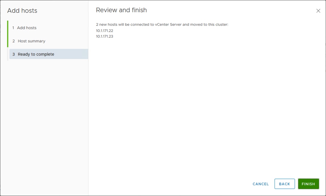
7. The added ESXi host(s) will have Warnings that the ESXi Shell and SSH have been enabled. These warnings can be suppressed.
Set Up VMkernel Ports and Virtual Switch
ESXi Host VM-Host-Infra-02 and VM-Host-Infra-03
To set up the VMkernel ports and the virtual switches on the ESXi host, follow these steps:
1. In the vCenter HTML5 Interface, under Hosts and Clusters choose the ESXi host.
2. In the center pane, choose the Configure tab.
3. In the list, choose Virtual switches under Networking.
4. Expand Standard Switch: vSwitch0.
5. Choose EDIT to Edit settings.
6. Change the MTU to 9000.
7. Choose Teaming and failover located on the left.
8. In the Failover order section, use the arrow icons to move the vmnics until both are Active adapters.
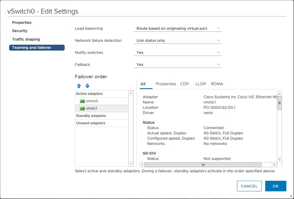
![]() Speeds will appear as 20 Gbit/s for UCS blades not equipped with a port expander.
Speeds will appear as 20 Gbit/s for UCS blades not equipped with a port expander.
9. Click OK.
10. In the center pane, to the right of VM Network click … > Edit Settings to edit settings.
11. Rename the port group to Site1-IB and enter <site1-ib-vlan-id> in the VLAN ID field.
12. Click OK to finalize the edits for the Site1-IB port group.
13. Still within the center pane, click Add Networking to create the Common-Services port group.
14. Select Virtual Machine Port Group for a Standard Switch and click NEXT.
15. Leave Select an existing standard switch selected with the default of vSwitch0 and click NEXT.
16. Provide the name Common-Services for the Network label and specify the <common-services-vlan-id> in the VLAN ID field and click NEXT.
17. Click FINISH to create the port group.
18. Located on the left under Networking, choose VMkernel adapters.
19. In the center pane, click Add Networking.
20. Make sure VMkernel Network Adapter is selected and click NEXT.
21. Choose an existing standard switch and click BROWSE. Choose vSwitch0 and click OK. Click NEXT.
22. For Network label, enter VMkernel-Infra-NFS.
23. Enter <infra-nfs-vlan-id> for the VLAN ID.
24. Choose Custom for MTU and make sure 9000 is entered.
25. Leave the Default TCP/IP stack selected and do not choose any of the Enabled services. Click NEXT.
26. Choose Use static IPv4 settings and enter the IPv4 address and subnet mask for the Infra-NFS VMkernel port for this ESXi host.
27. Click NEXT.
28. Review the settings and click FINISH to create the VMkernel port.
29. On the left under Networking, choose Virtual switches. Then expand vSwitch0. The properties for vSwitch0 should be similar to the following example:
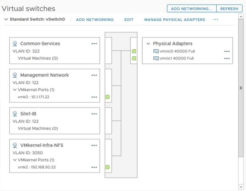
30. Repeat this procedure for all hosts being added.
ESXi Hosts created other than VM-Host-Infra-01
To mount the required datastores, follow these steps on the ESXi host(s):
1. From the vCenter Home screen, choose Menu > Storage.
2. Located on the left, expand FlexPod-DC.
3. Located on the left, right-click infra_datastore_1 and choose Mount Datastore to Additional Hosts.
4. Choose the ESXi host(s) and click OK.
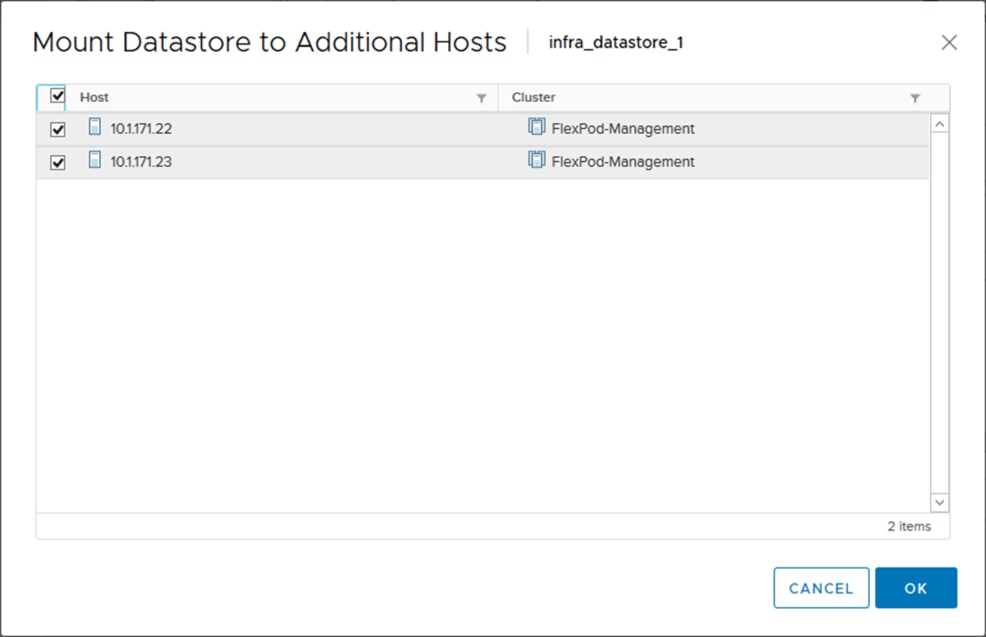
5. Repeat steps 1-4 to mount the infra_swap and any additional datastores created to the ESXi host(s).
6. Choose infra_datastore. In the center pane, choose Hosts. Verify the ESXi host(s) now has the datastore mounted. Repeat this process to also verify that infra_swap is also mounted.
ESXi Hosts created other than VM-Host-Infra-01
To configure Network Time Protocol (NTP) on the ESXi host(s), follow these steps:
1. In the vCenter HTML5 Interface, under Hosts and Clusters choose the ESXi host.
2. In the center pane, choose the Configure tab.
3. In the list under System, choose Time Configuration.
4. To the right of Manual Time Configuration, click EDIT.
5. Set the correct local time and click OK.
6. To the right of Network Time Protocol, click EDIT.
7. Choose the Enable checkbox.
8. Enter the two Nexus switch NTP IP addresses in the NTP servers box separated by a comma.
9. Click the Start NTP Service checkbox.
10. Use the drop-down list to choose Start and stop with host.
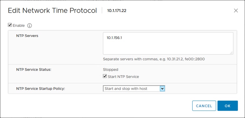
11. Click OK to save the configuration changes.
12. Verify that NTP service is now enabled and running and the clock is now set to approximately the correct time.
ESXi Hosts created other than VM-Host-Infra-01
To configure host swap on the ESXi host(s), follow these steps on the host:
1. In the vCenter HTML5 Interface, under Hosts and Clusters choose the ESXi host.
2. In the center pane, choose the Configure tab.
3. In the list under System, choose System Swap.
4. Located on the right, click EDIT.
5. Choose Can use datastore and use the drop-down list to choose infra_swap. Leave all other settings unchanged.
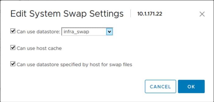
6. Click OK to save the configuration changes.
7. In the list under Virtual Machines, choose Swap File Location.
8. Located on the right, click EDIT.
9. Choose infra_swap and click OK.
Change ESXi Power Management Policy
ESXi Hosts created other than VM-Host-Infra-01
To change the ESXi power management policy, follow these steps:
1. In the list under Hardware, choose Overview. Scroll to the bottom and to the right of Power Management, choose EDIT POWER POLICY.
2. Choose High performance and click OK.
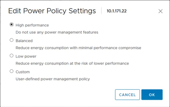
All ESXi Hosts
To add the iSCSI configuration to the ESXi hosts, follow these steps:
1. In the vSphere HTML5 Client, under Hosts and Clusters, choose the ESXi host.
2. In the center pane, click Configure. In the list under Networking, select Virtual switches.
3. In the center pane, expand iScsiBootvSwitch. Click EDIT to edit settings for the vSwitch.
4. Change the MTU to 9000 and click OK.
5. Choose … > Edit Settings to the right of iScsiBootPG. Change the Network label to iScsiBootPG-A and click OK.
6. Choose … > Edit Settings to the right of the VMkernel Port IP address. Change the MTU to 9000.
7. Click IPv4 settings on the left. Change the IP address to a unique IP address in the Infra-iSCSI-A subnet but outside of the Cisco UCS iSCSI-IP-Pool-A.
![]() It is recommended to enter a unique IP address for this VMkernel port to avoid any issues related to IP Pool reassignments.
It is recommended to enter a unique IP address for this VMkernel port to avoid any issues related to IP Pool reassignments.
8. Click OK.
9. In the upper right-hand corner, choose ADD NETWORKING to add another vSwitch.
10. Make sure VMkernel Network Adapter is selected and click NEXT.
11. Choose New standard switch and change the MTU to 9000. Click NEXT.
12. Choose ![]() to add an adapter. Make sure vmnic5 is highlighted and click OK. vmnic5 should now be under Active adapters. Click NEXT.
to add an adapter. Make sure vmnic5 is highlighted and click OK. vmnic5 should now be under Active adapters. Click NEXT.
13. Enter iScsiBootPG-B for the Network label, leave VLAN ID set to None (0), choose Custom – 9000 for MTU, and click NEXT.
14. Choose Use static IPv4 settings. Enter a unique IP address and netmask in the Infra-iSCSI-B subnet but outside of the Cisco UCS iSCSI-IP-Pool-B. Click NEXT.
15. Click FINISH to complete creating the vSwitch and the VMkernel port.
16. In the list under Storage, choose Storage Adapters.
17. Choose the iSCSI Software Adapter and below, choose the Dynamic Discovery tab.
18. Click Add.
19. Enter the IP address of the storage controller’s Infra-SVM LIF iscsi-lif-01a and click OK.
20. Repeat this process to add the IPs for iscsi-lif-02a, iscsi-lif-01b, and iscsi-lif-02b.
21. Under Storage Adapters, click Rescan Adapter to rescan the iSCSI Software Adapter.
22. Under Static Discovery, four static targets should now be listed.
23. Under Paths, four paths should now be listed with two of the paths having the “Active (I/O)” Status.
Add the ESXi Host(s) to the VMware Virtual Distributed Switch
ESXi Hosts created other than VM-Host-Infra-01
To add the ESXi host(s) to the VMware vDS, follow these steps on the host:
1. After logging into the VMware vSphere HTML5 Client, choose Networking under Menu.
2. Right-click the vDS (vDS0) and click Add and Manage Hosts.
3. Make sure Add hosts is selected and click NEXT.
4. Click the green + sign to add New hosts. Choose the configured FlexPod Management host(s) and click OK. Click NEXT.
5. Choose vmnic2 on each host and click Assign uplink. Choose Uplink 1 and click OK. Choose vmnic3 on each host and click Assign uplink. Choose Uplink 2 and click OK. If more than one host is being connected to the vDS, use the Apply this uplink assignment to the rest of the hosts checkbox.
![]() It is important to assign the uplinks as shown below. This allows the port groups to be pinned to the appropriate Cisco UCS fabric.
It is important to assign the uplinks as shown below. This allows the port groups to be pinned to the appropriate Cisco UCS fabric.
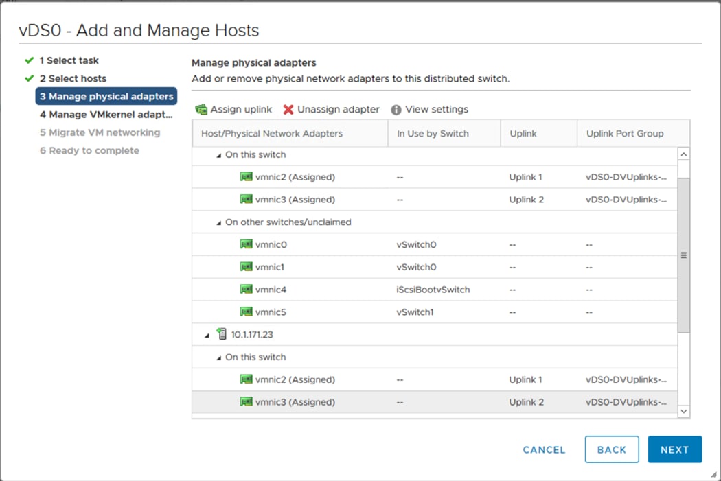
6. Click NEXT.
7. Do not migrate any VMkernel ports and click NEXT.
8. Do not migrate any VM ports and click NEXT.
9. Click FINISH to complete adding the ESXi host(s) to the vDS.
Add the vMotion VMkernel Port(s) to the ESXi Host
All ESXi Hosts
To add the vMotion VMkernel Port to the ESXi host(s) on the VMware vDS, follow these steps on the host:
1. In the vCenter HTML5 Interface, under Hosts and Clusters choose the ESXi host.
2. In the center pane, click the Configure tab.
3. In the list under Networking, choose VMkernel adapters.
4. Choose Add Networking to Add host networking.
5. Make sure VMkernel Network Adapter is selected and click NEXT.
6. Choose BROWSE to the right of Select an existing network.
7. Choose vMotion on the vDS and click OK.
8. Click NEXT.
9. Make sure the Network label is vMotion with the vDS in parenthesis. From the drop-down list, select Custom for MTU and make sure the MTU is set to 9000. Choose the vMotion TCP/IP stack and click NEXT.
10. Choose Use static IPv4 settings and input the host’s vMotion IPv4 address and Subnet mask.
11. Click NEXT.
12. Review the parameters and click FINISH to add the vMotion VMkernel port.
13. Optionally, repeat this process to add two more vMotion VMkernel ports.
Solution Deployment - Management Tools
NetApp Virtual Storage Console 9.7.1 Deployment Procedure
This section describes the deployment procedures for the NetApp Virtual Storage Console (VSC).
Virtual Storage Console 9.7.1 Pre-installation Considerations
The following licenses are required for VSC on storage systems that run ONTAP 9.7.1 or above:
● Protocol licenses (NFS, iSCSI)
● NetApp FlexClone® (for provisioning and cloning and vVol)
● NetApp SnapRestore® (for backup and recovery)
● The NetApp SnapManager® Suite
● NetApp SnapMirror® or NetApp SnapVault®
![]() The Backup and Recovery capability has been integrated with SnapCenter and requires additional licenses for SnapCenter to perform backup and recovery of virtual machines and applications.
The Backup and Recovery capability has been integrated with SnapCenter and requires additional licenses for SnapCenter to perform backup and recovery of virtual machines and applications.
Table 23. Port Requirements for VSC
| Port |
Requirement |
| 443 (HTTPS) |
Secure communications between VMware vCenter Server and the storage systems |
| 8143 (HTTPS) |
VSC listens for secure communications |
| 9083 (HTTPS) |
VASA Provider uses this port to communicate with the vCenter Server and obtain TCP/IP settings |
Install Virtual Storage Console 9.7.1
To install the VSC 9.7.1 software by using an Open Virtualization Format (OVF) deployment, follow these steps:
1. Login to vCenter and navigate to Hosts and Clusters.
2. Select ACTIONS for the FlexPod-DC datacenter and choose Deploy OVF Template.
3. Browse to the VSC OVA file downloaded from the NetApp Support site.
4. Enter the VM name and choose a datacenter or folder in which to deploy and click NEXT.
5. Choose a host cluster resource in which to deploy OVA and click NEXT.
6. Review the details and accept the license agreement.
7. Choose the infra_datastore_1 volume and choose the Thin Provision option for the virtual disk format.
8. From Select Networks, choose a destination network (Site1-IB) and click NEXT.
9. From Customize Template, enter the VSC administrator password, vCenter name or IP address and other configuration details and click NEXT.
10. Review the configuration details entered and click FINISH to complete the deployment of NetApp-VSC VM.
11. Power on the NetApp-VSC VM and open the VM console.
12. Verify that VSC, VASA Provider, and SRA services are running after the deployment is completed.
13. Networking configuration and vCenter registration information was provided during the OVF template customization, therefore after the VM is running, VSC and vSphere API for Storage Awareness (VASA) is registered with vCenter.
14. Refresh the Home Screen and confirm that the NetApp VSC is installed.
![]() If the virtual appliance for VSC, VASA Provider, and SRA is not registered with any vCenter Server, use https://appliance_ip:8143/Register.html to register the VSC instance.
If the virtual appliance for VSC, VASA Provider, and SRA is not registered with any vCenter Server, use https://appliance_ip:8143/Register.html to register the VSC instance.
Download the NetApp NFS Plug-in for VAAI
To download the NetApp NFS Plug-in for VAAI, follow this step:
1. Download the NetApp NFS Plug-in 1.1.2 for VMware .vib file from the NFS Plugin Download page and save it to your local machine or admin host.
Install the NetApp NFS Plug-in for VAAI
![]() The NFS Plug-in for VAAI was already installed on the ESXi hosts along with the Cisco UCS VIC drivers. It is not necessary to re-install it here.
The NFS Plug-in for VAAI was already installed on the ESXi hosts along with the Cisco UCS VIC drivers. It is not necessary to re-install it here.
To install the NetApp NFS Plug-in for VAAI, follow these steps:
1. Rename the .vib file that you downloaded from the NetApp Support Site to NetAppNasPlugin.vib to match the predefined name that VSC uses.
2. Click Settings in the VSC Getting Started page.
3. Click NFS VAAI Tools tab.
4. Click Change in the Existing version section.
5. Browse and choose the renamed .vib file, and then click Upload to upload the file to the virtual appliance.
6. In the Install on ESXi Hosts section, choose the ESXi host on which you want to install the NFS Plug-in for VAAI, and then click Install.
7. Reboot the ESXi host after the installation finishes.
The VASA provider for ONTAP is enabled by default during the installation of the NetApp Virtual Storage Console (VSC) 9.7.1. To verify the VASA provider was enabled, follow these steps:
1. From the vSphere Client, click Menu > Virtual Storage Console. Click Settings.
2. Click Manage Capabilities in the Administrative Settings tab.
3. In the Manage Capabilities dialog box if not enabled, click Enable VASA Provider slider.
4. Enter the IP address of the virtual appliance for VSC, VASA Provider, and VMware Storage Replication Adapter (SRA) and the administrator password, and then click Apply.
Discover and Add Storage Resources
To Add storage resources for the Monitoring and Host Configuration capability and the Provisioning and Cloning capability, follow these steps:
1. Using the vSphere Web Client, log in to the vCenter Server as the FlexPod admin user. If the vSphere Web Client was previously opened, close the tab, and then reopen it.
2. In the Home screen, click the Home tab and click Virtual Storage Console.
![]() When using the cluster admin account, add storage from the cluster level.
When using the cluster admin account, add storage from the cluster level.
![]() You can modify the storage credentials with the vsadmin account or another SVM level account with role-based access control (RBAC) privileges. Refer to the ONTAP 9 Administrator Authentication and RBAC Power Guide for additional information.
You can modify the storage credentials with the vsadmin account or another SVM level account with role-based access control (RBAC) privileges. Refer to the ONTAP 9 Administrator Authentication and RBAC Power Guide for additional information.
3. Choose Storage Systems > Add.
4. Click Overview > Getting Started, and then click ADD button under Add Storage System.
5. Specify the vCenter Server instance where the storage will be located.
6. In the IP Address/Hostname field, enter the storage cluster management IP.
7. Confirm Port 443 to Connect to this storage system.
8. Enter admin for the user name and the admin password for the cluster.
9. Click Save to add the storage configuration to VSC.
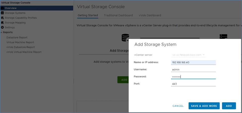
10. Wait for the Storage Systems to update. You might need to click Refresh to complete this update.
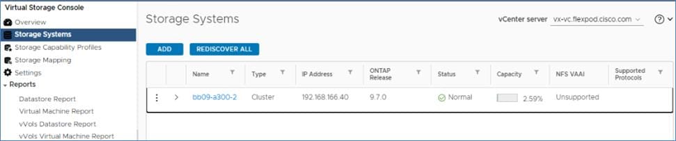
Discover the Cluster and SVMs
To Discover the cluster and SVMs with the cluster admin account, follow these steps:
1. From the vSphere Client Home page, click Hosts and Clusters.
2. Right-click the FlexPod-DC datacenter then click NetApp VSC > Update Host and Storage Data and click Yes.
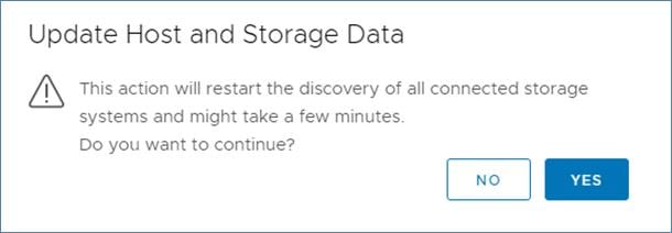
3. Click OK.
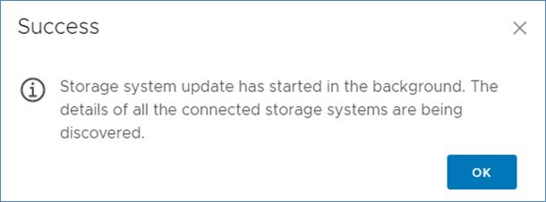
Optimal Storage Settings for ESXi Hosts
VSC enables the automated configuration of storage-related settings for all ESXi hosts that are connected to NetApp storage controllers. To use these settings, follow these steps:
1. From the VMware vSphere Web Client Home page, click vCenter > Hosts.
2. Choose a host and then click Actions > NetApp VSC > Set Recommended Values.
3. In the NetApp Recommended Settings dialog box, choose all the values for your system.
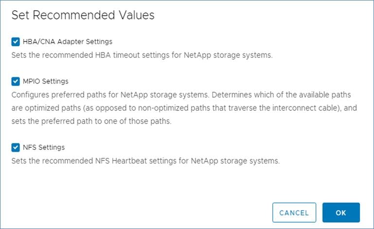
![]() This functionality sets values for HBAs and converged network adapters (CNAs), sets appropriate paths and path-selection plug-ins, and verifies appropriate settings for software-based I/O (NFS). A vSphere host reboot may be required after applying the settings.
This functionality sets values for HBAs and converged network adapters (CNAs), sets appropriate paths and path-selection plug-ins, and verifies appropriate settings for software-based I/O (NFS). A vSphere host reboot may be required after applying the settings.
4. Click OK.
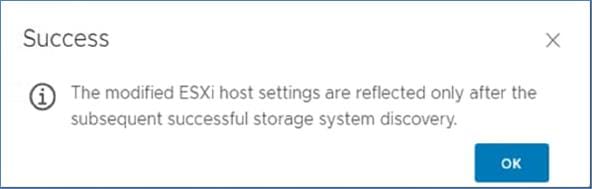
Virtual Storage Console 9.7.1 Provisioning Datastores
Using VSC, the administrator can provision an NFS, FC or iSCSI datastore and attach it to a single host or multiple hosts in the cluster. The following steps describe provisioning a datastore and attaching it to the cluster.
![]() It is a NetApp best practice to use Virtual Storage Console (VSC) to provision datastores for the FlexPod infrastructure. When using VSC to create vSphere datastores, all NetApp storage best practices are implemented during volume creation and no additional configuration is needed to optimize performance of the datastore volumes.
It is a NetApp best practice to use Virtual Storage Console (VSC) to provision datastores for the FlexPod infrastructure. When using VSC to create vSphere datastores, all NetApp storage best practices are implemented during volume creation and no additional configuration is needed to optimize performance of the datastore volumes.
Storage Capabilities
A storage capability is a set of storage system attributes that identifies a specific level of storage performance (storage service level), storage efficiency, and other capabilities such as encryption for the storage object that is associated with the storage capability.
Create the Storage Capability Profile
To leverage the automation features of VASA two primary components must first be configured. The Storage Capability Profile (SCP) and the VM Storage Policy. The Storage Capability Profile expresses a specific set of storage characteristics into one or more profiles used to when provisioning a Virtual Machine. The SCP is specified as part of VM Storage Policy which is specified when you deploy a virtual machine. NetApp Virtual Storage Console comes with two pre-configured Storage Capability Profiles- Platinum and Bronze.
![]() Adaptive QoS policies are not currently supported with VSC 9.7.1. Storage Capability Profiles (SCP) can still be created with Max IOPS and Min IOPS defined.
Adaptive QoS policies are not currently supported with VSC 9.7.1. Storage Capability Profiles (SCP) can still be created with Max IOPS and Min IOPS defined.
To review or edit one of the built-in profiles pre-configured with VSC 9.7.1 follow these steps:
1. In the NetApp Virtual Storage Console click Storage Capability Profiles.
2. Choose the Platinum Storage Capability Profile and choose Clone from the toolbar.
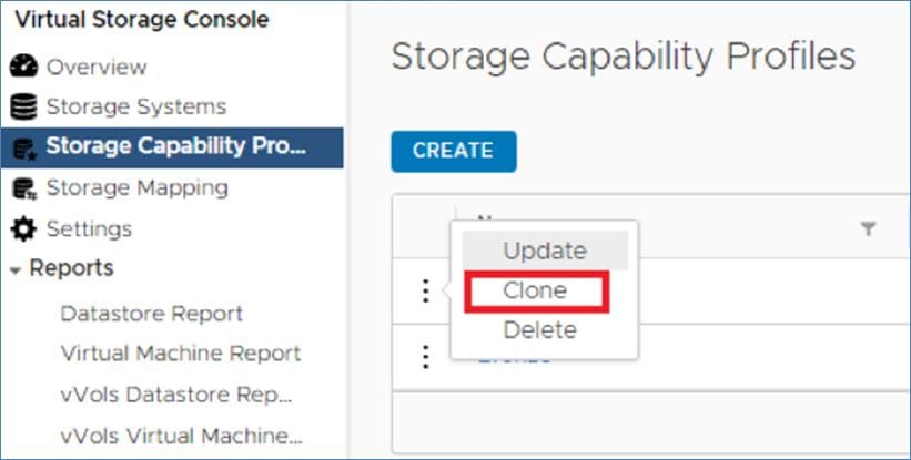
3. Enter a name for the cloned SCP and add a description if desired.
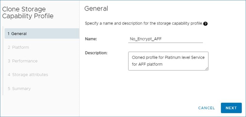
4. Choose ALL Flash FAS(AFF) for the storage platform. Click Next.
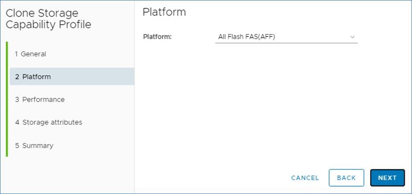
5. Choose None to allow unlimited performance or set a the desired minimum and maximum IOPS for the QoS policy group.
6. On the Storage attributes page, Change the Encryption and Tiering policy to the desired settings and click NEXT.
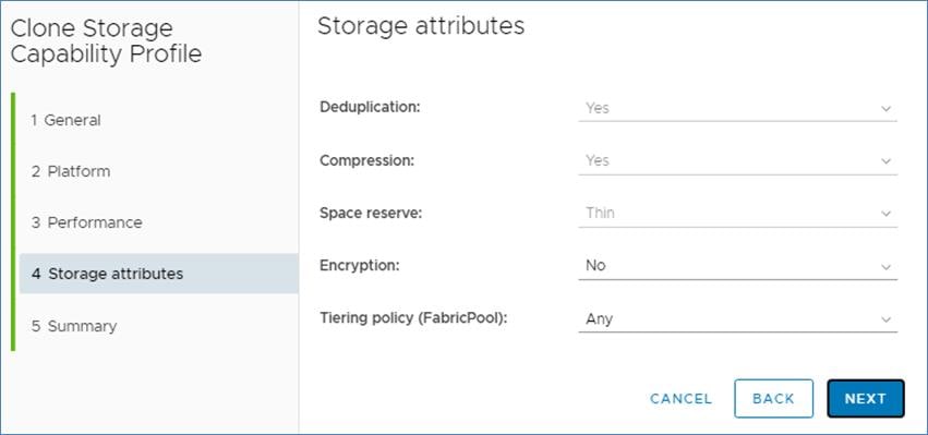
7. Review the summary page and click FINISH to create the storage capability profile.
![]() As a best practice it is always recommended to create clone and edit the Capability profile rather than changing the Default one.
As a best practice it is always recommended to create clone and edit the Capability profile rather than changing the Default one.
Create a VM storage policy and associate a storage capability profile (SCP) to the datastore that meets the requirements defined in the SCP. To create a new VM Storage policy, follow these steps:
1. Navigate to Policies and Profiles from the vSphere Client menu.
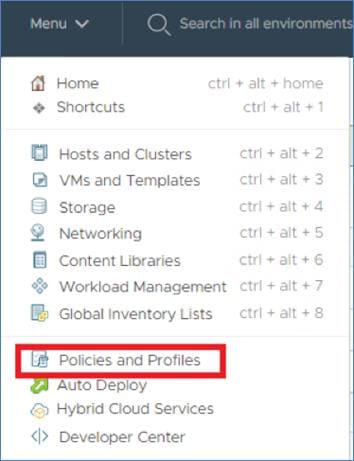
2. Navigate to Policies and Profiles from the vSphere Client menu.
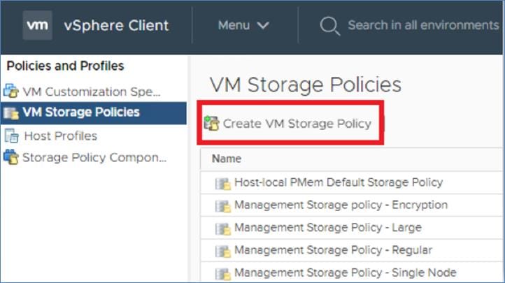
3. Create a name for the VM storage policy and enter a description and click NEXT.
4. Choose Enable rules for NetApp.clustered.Data.ONTAP.VP.VASA10 storage located under the Datastore specific rules section and click NEXT.
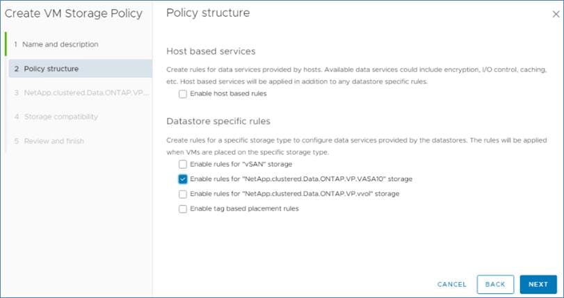
5. On the Placement tab select the SCP created in the previous step and click NEXT.
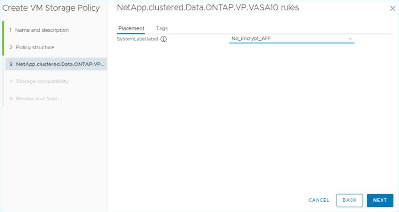
6. The datastores with matching capabilities are displayed, click NEXT.
7. Review the policy summary and click FINISH.
Provision NFS Datastore
To provision the NFS datastore, follow these steps:
1. From the Virtual Storage Console Home page, click Overview.
2. In the Getting Started tab, click Provision.
3. Click Browse to choose the destination to provision the datastore as per the next step.
4. Choose the type as NFS and Enter the datastore name.
5. Provide the size of the datastore and the NFS Protocol.
6. Check the storage capability profile and click NEXT.
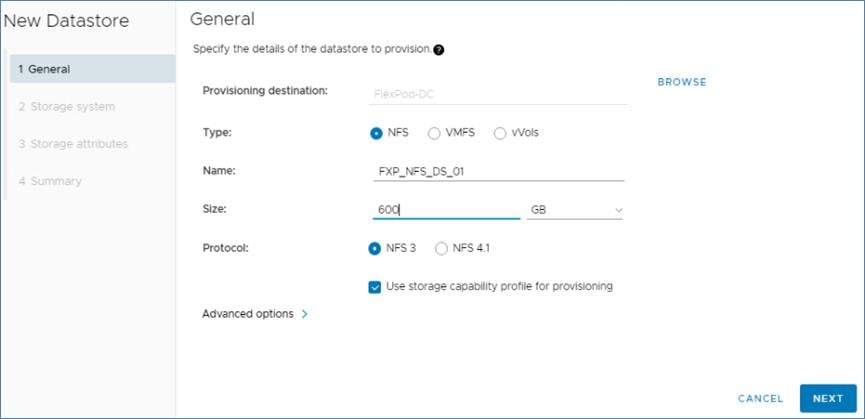
7. Choose the desired Storage Capability Profile, cluster name, and the desired SVM to create the datastore. In this example, the Infra-SVM is selected.
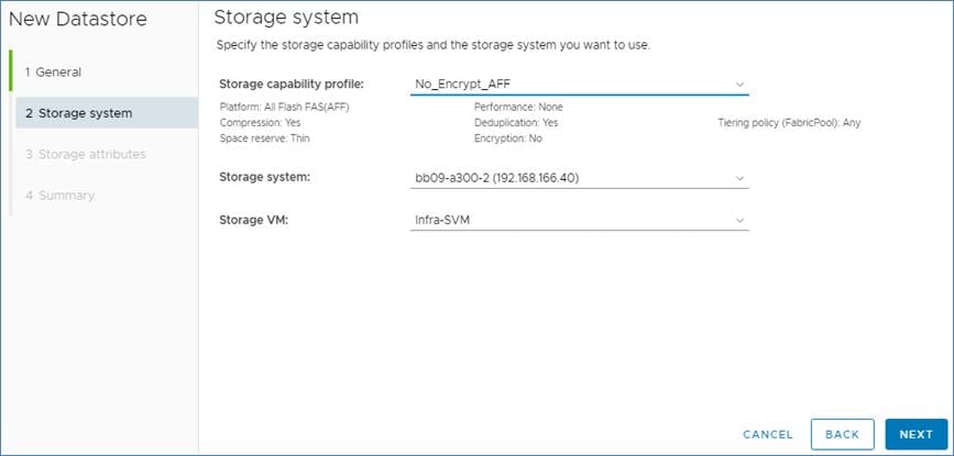
8. Click NEXT.
9. Choose the aggregate name and click NEXT.
10. Review the Summary and click FINISH.
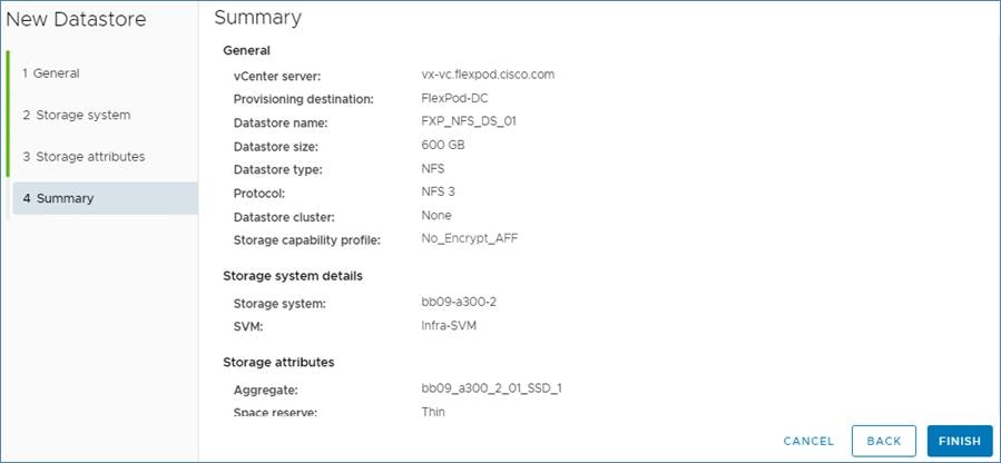
![]() The datastore is created and mounted on the hosts in the cluster. Click Refresh from the vSphere Web Client to see the newly created datastore or it is also listed in the VSC home page > Traditional Dashboard > Datastores view. Also, VSC Home page > Reports > Datastore Report should be listing the newly created datastore.
The datastore is created and mounted on the hosts in the cluster. Click Refresh from the vSphere Web Client to see the newly created datastore or it is also listed in the VSC home page > Traditional Dashboard > Datastores view. Also, VSC Home page > Reports > Datastore Report should be listing the newly created datastore.
NetApp VASA Provider enables you to create and manage VMware virtual volumes (vVols). A vVols datastore consists of one or more FlexVol volumes within a storage container (also called "backing storage"). A virtual machine can be spread across one vVols datastore or multiple vVols datastores. All FlexVol volumes within the storage container must use the same protocol (NFS, iSCSI) and the same SVMs.
![]() Lab testing has shown that if a virtual machine (VM) has one or more disks in vVol datastores and the VM is migrated to another host, just at the end of the migration the VM can be stunned or frozen for 45 or more seconds. Total observed vMotion time noted as approximately 80 seconds.
Lab testing has shown that if a virtual machine (VM) has one or more disks in vVol datastores and the VM is migrated to another host, just at the end of the migration the VM can be stunned or frozen for 45 or more seconds. Total observed vMotion time noted as approximately 80 seconds.
Verify NDMP Vserver Scope Mode
To verify the NDMP Vserver scope mode, follow these steps:
1. View NDMP scope mode with the following command:
system services ndmp node-scope-mode status
NDMP node-scope-mode is enabled.
2. Disable NDMP node-scoped mode.
system services ndmp node-scope-mode off
NDMP node-scope-mode is disabled.
3. Enable NDMP services on the vserver.
vserver services ndmp on -vserver Infra-SVM
Create the Storage Capability Profile
You can select one or more VASA Provider storage capability profiles for a vVols datastore. You can also specify a default storage capability profile for any vVols datastores that are automatically created in that storage container.
To create storage capability profile for the vVol datastore, follow these steps:
1. In the NetApp Virtual Storage Console click Storage Capability Profiles.
2. Choose the Platinum Storage Capability Profile and choose Clone from the toolbar.

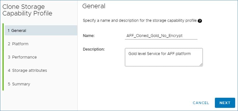
3. Choose All Flash FAS(AFF) for the storage platform and click Next.
4. Choose None to allow unlimited performance or set a the desired minimum and maximum IOPS for the QoS policy group. You can set the value for Max IOPS, which enables you to use the QoS functionality.
![]() When applied for a virtual datastore, a QoS policy with "MAX IOPS" value is created for each data vVols.
When applied for a virtual datastore, a QoS policy with "MAX IOPS" value is created for each data vVols.
![]() When you select ONTAP Service Level, then the existing adaptive QoS policies of ONTAP are applied to a data vVols. You can select one of three service levels: Extreme, Performance, or Value. The ONTAP service level is applicable only to vVols datastores.
When you select ONTAP Service Level, then the existing adaptive QoS policies of ONTAP are applied to a data vVols. You can select one of three service levels: Extreme, Performance, or Value. The ONTAP service level is applicable only to vVols datastores.
5. On the Storage attributes page, change the Encryption and Tiering policy to the desired settings and click NEXT.
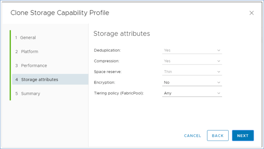
6. Review the summary page and choose FINISH to create the storage capability profile.
Create a VM storage policy and associate a storage capability profile (SCP) to the datastore that meets the requirements defined in the SCP. To create a new VM Storage policy, follow these steps:
1. Navigate to Policies and Profiles from the vSphere Client menu.
2. Click Create VM Storage Policy.
3. Create a new name for the VM storage Policy and enter a description and click NEXT.
4. Choose Enable rules for NetApp.clustered.Data.ONTAP.VP.VASA.10 storage and NetApp.clustered.Data.ONTAP.VP.vvol storage, located under the Datastore specific rules section and click NEXT.
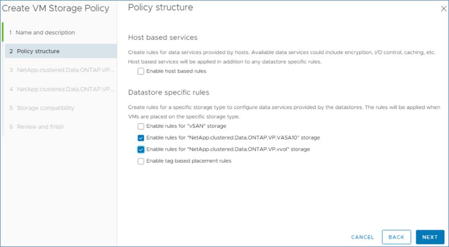
5. On the Placement tab for VP.VASA and VP.vvol storage rules select the SCP created in the previous step.
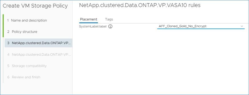
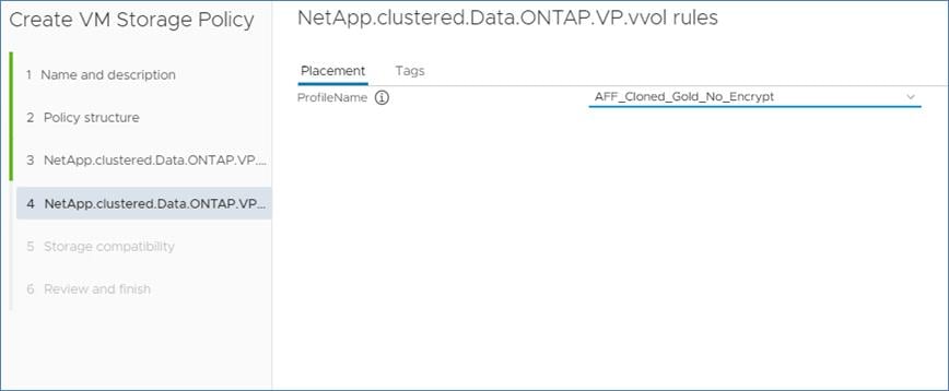
6. The datastores with matching capabilities are displayed, click NEXT.
7. Review the Policy Summary and click Finish.
To provision the vVols datastore over NFS protocol, follow these steps:
1. From the Virtual Storage Console Home page, click Overview.
2. In the Getting Started tab, click Provision.
3. Click Browse to choose the destination to provision the datastore as per the next step.
4. Choose the type as vVols and Enter the datastore name.
5. Select NFS for protocol and click Next.
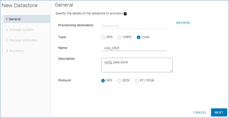
6. Select the Storage capability profile created earlier for vVols.
7. Select the NFS storage server and the NetApp Storage SVM where the vVols needs to be created and click Next.
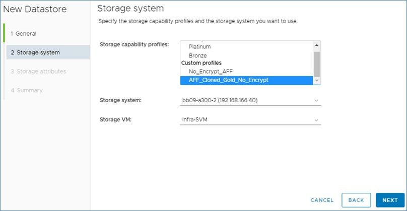
8. Create new vVols or select existing vVols.
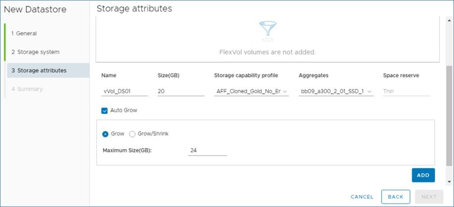
9. Check the storage capability profile and click ADD. The default storage profile should be added automatically.
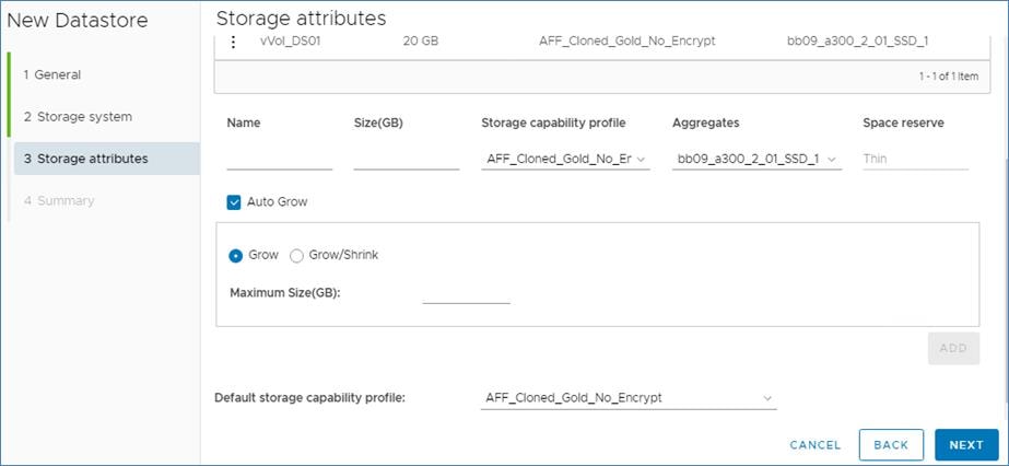
![]() You can create multiple vVols for a datastore.
You can create multiple vVols for a datastore.
10. Check the storage capability profile and click NEXT.
11. Review all the fields on the summary page and click Finish.
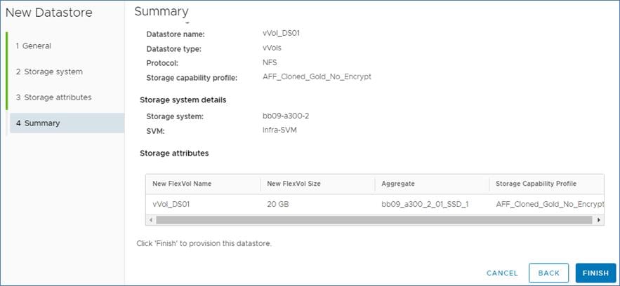
12. Verify in the vVols Datastore report the vVols is mounted correctly, go to VSC->Reports-> vVols Datastore Report.
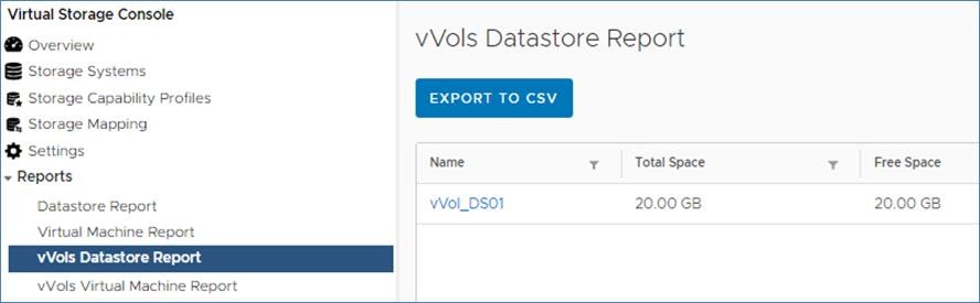
![]() To provision vVols for FC or ISCSI protocol, select it in the General tab and provide protocol-specific storage attributes in the Storage Attributes Inputs to create vVols successfully.
To provision vVols for FC or ISCSI protocol, select it in the General tab and provide protocol-specific storage attributes in the Storage Attributes Inputs to create vVols successfully.
SnapCenter Software is a simple, centralized, scalable platform that provides application-consistent data protection for applications, databases, host file systems, and VMs running on ONTAP systems anywhere in the Hybrid Cloud.
NetApp SnapCenter Architecture
The SnapCenter platform is based on a multitier architecture that includes a centralized management server (SnapCenter Server) and a SnapCenter host agent. The host agent that performs virtual machine and datastore backups for VMware vSphere is the SnapCenter Plug-in for VMware vSphere. It is packaged as a Linux appliance (Debian-based Open Virtual Appliance format) and is no longer part of the SnapCenter Plug-ins Package for Windows. Additional information on deploying SnapCenter server for application backups can be found in the documentation listed below.
This guide focuses on deploying and configuring the SnapCenter plug-in for VMware vSphere to protect virtual machines and VM datastores.
You must install SnapCenter Server and the necessary plug-ins to support application-consistent backups for Microsoft SQL, Microsoft Exchange, Oracle databases and SAP HANA. Application level protection is beyond the scope of this deployment guide. Refer to the SnapCenter documentation for more information or the application specific CVD’s and technical reports for detailed information on how to deploy SnapCenter for a specific application configuration.
● SnapCenter 4.3 Documentation Center
● SAP HANA Backup and Recovery with SnapCenter
● FlexPod Datacenter with Microsoft SQL Server 2017 on Linux VM Running on VMware and Hyper-V
● SnapCenter Plug-in for VMware vSphere Documentation
Install SnapCenter Plug-In for VMware vSphere 4.3.1
NetApp SnapCenter Plug-in for VMware vSphere is a Linux-based virtual appliance which enables the SnapCenter Plug-in for VMware vSphere to protect virtual machines and VMware datastores.
Host and Privilege Requirements for the SnapCenter Plug-In for VMware vSphere
Review the following requirements before you install the SnapCenter Plug-in for VMware vSphere virtual appliance:
● You must deploy the SnapCenter Plug-in for VMware vSphere virtual appliance as a Linux VM.
● You should deploy the virtual appliance on the vCenter Server.
● You must not deploy the virtual appliance in a folder that has a name with special characters.
● You must deploy and register a separate, unique instance of the virtual appliance for each vCenter Server.
Table 24. Port Requirements
| Port |
Requirement |
| 8080(HTTPS) bidirectional |
This port is used to manage the virtual appliance |
| 8144(HTTPs) bidirectional |
Communication between SnapCenter Plug-in for VMware vSphere and vCenter |
| 443 (HTTPS) |
Communication between SnapCenter Plug-in for VMware vSphere and vCenter |
License Requirements for SnapCenter Plug-In for VMware vSphere
The following licenses are required to be installed on the ONTAP storage system to backup and restore VM’s in the virtual infrastructure:
Table 25. SnapCenter Plug-in for VMware vSphere License Requirements
| Product |
License Requirement |
| ONTAP |
SnapManager Suite: Used for backup operations One of these: SnapMirror or SnapVault (for secondary data protection regardless of the type of relationship) |
| ONTAP Primary Destinations |
To perform protection of VMware VMs and datastores the following licenses should be installed: SnapRestore: used for restore operations FlexClone: used for mount and attach operations |
| ONTAP Secondary Destinations |
To perform protection of VMware VMs and datastores only: FlexClone: used for mount and attach operations |
| VMware |
vSphere Standard, Enterprise, or Enterprise Plus A vSphere license is required to perform restore operations, which use Storage vMotion. vSphere Essentials or Essentials Plus licenses do not include Storage vMotion.
|
![]() It is recommended but not required, that you add SnapCenter Standard licenses to secondary destinations. If SnapCenter Standard licenses are not enabled on secondary systems, you cannot use SnapCenter after performing a failover operation. A FlexClone license on secondary storage is required to perform mount and attach operations. A SnapRestore license is required to perform restore operations.
It is recommended but not required, that you add SnapCenter Standard licenses to secondary destinations. If SnapCenter Standard licenses are not enabled on secondary systems, you cannot use SnapCenter after performing a failover operation. A FlexClone license on secondary storage is required to perform mount and attach operations. A SnapRestore license is required to perform restore operations.
Download and Deploy the SnapCenter Plug-In for VMware vSphere 4.3.1
To download and deploy the SnapCenter Plug-in for VMware vSphere appliance, follow these steps:
1. Download SnapCenter Plug-in for VMware vSphere OVA file from NetApp support site (https://mysupport.netapp.com).
2. From VMware vCenter, navigate to the VMs and Templates tab, right-click FlexPod-DC and choose Deploy OVF Template.
3. Specify the location of the OVF Template and click NEXT.
4. On the Select a name and folder page, enter a unique name and location for the VM and click NEXT to continue.
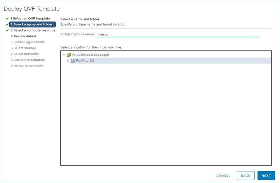
5. On the Select a compute resource page, choose a resource where you want to run the deployed VM template, and click NEXT.
6. On the Review details page, verify the OVA template details and click NEXT.
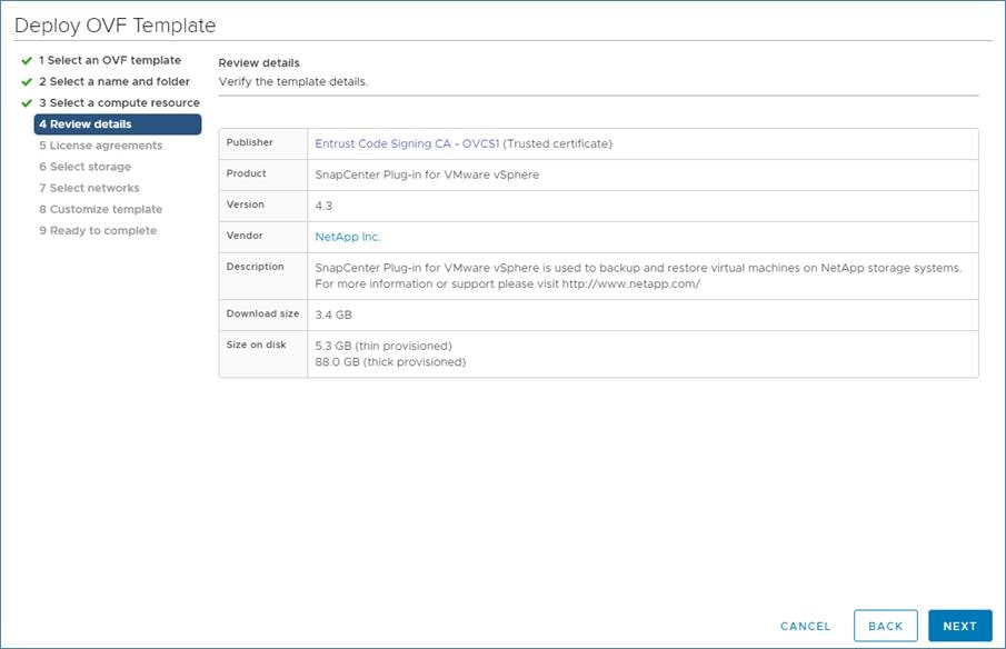
7. On the License agreements page, check the box I accept all license agreements.
8. On the Select storage page, change the datastore virtual disk format to Thin Provision and click NEXT.
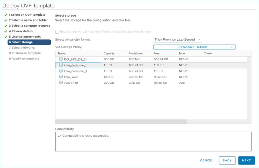
9. On the Select networks page, choose a source network, and map it to a destination network, and then click NEXT.
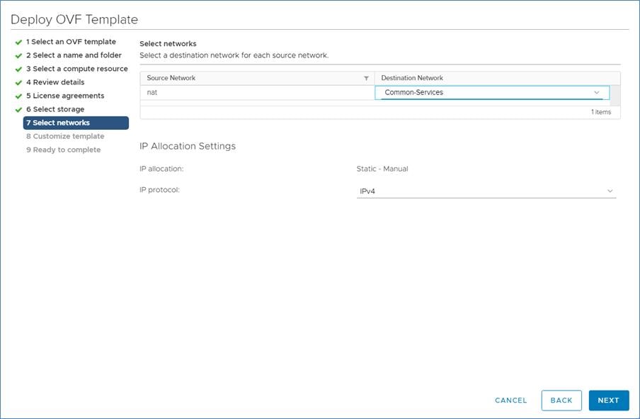
10. On the Customize template page, do the following:
a. In Register to existing vCenter, enter the vCenter credentials.
b. In Create SnapCenter Plug-in for VMware vSphere credentials, enter the SnapCenter Plug-in for VMware vSphere credentials.
c. In Create SCV credentials, create a username and password for the SCV maintenance user.
d. In Setup Network Properties, enter the network information.
e. In Setup Date and Time, choose the time zone where the vCenter is located.
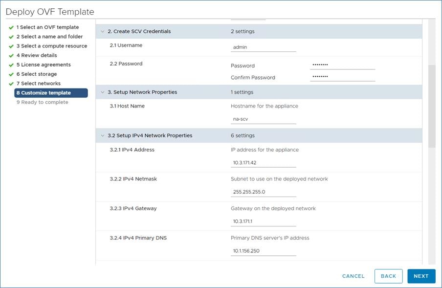
11. On the Ready to complete page, review the page and click FINISH.
12. Navigate to the VM where the virtual appliance was deployed, then click the Summary tab, and then click the Power On box to start the virtual appliance.
13. While the virtual appliance is powering on, click Install VMware tools in the Yellow banner displayed in the summary tab of the appliance.
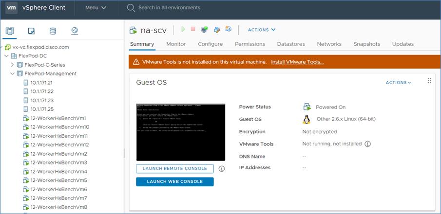
14. Log into SnapCenter Plug-in for VMware vSphere using the IP address displayed on the appliance console screen with the credentials that you provided in the deployment wizard. Verify on the Dashboard that the virtual appliance is successfully connected to vCenter and the SnapCenter Plug-in for VMware vSphere is successfully enabled and connected.
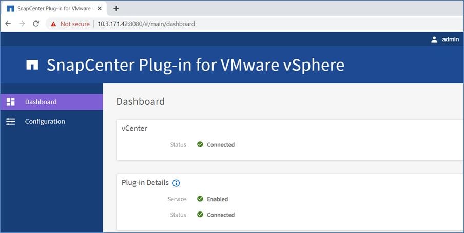
SnapCenter Plug-In for VMware vSphere in vCenter Server
After you have successfully installed the Plug-in for VMware vSphere, to configure SnapCenter and make it ready to backup virtual machines, follow these steps:
1. In your browser, navigate to VMware vSphere Web Client URL https://<vCenter Server>/ui.
2. After logging on to the vSphere Web Client you will see a blue banner indicating the SnapCenter plug-in was successfully deployed. Click the refresh button to activate the plug-in.
3. On the VMware vSphere Web Client page, click the menu and click SnapCenter Plug-in for VMware vSphere to launch the SnapCenter Plug-in for VMware GUI.
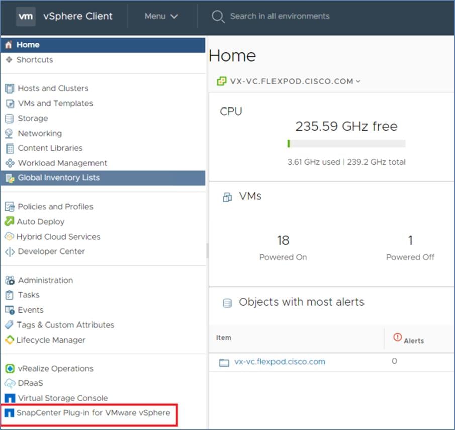
To add storage systems, follow these steps:
1. Go to the Storage Systems tab.
2. Click Add Storage System to add a cluster or SVM.
3. Enter vCenter, Storage System, user credentials, and other required information.
![]() Check the box for Log SnapCenter server events to syslog and Send AutoSupport Notification for failed operation to storage system.
Check the box for Log SnapCenter server events to syslog and Send AutoSupport Notification for failed operation to storage system.
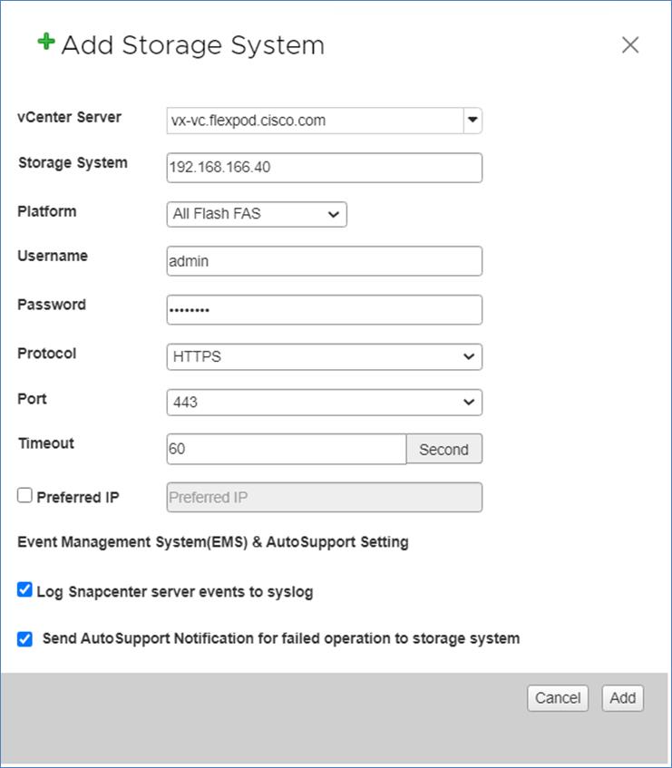
Create Backup Policies for Virtual Machines and Datastores
To create backup policies for VMs and datastores, follow these steps:
1. In the left Navigator pane of the VMware vSphere Web Client, click Policies.
2. On the Policies page, click New Policy in the toolbar.
3. On the New Backup Policy page, follow these steps:
a. Enter the policy name and a description.
b. Enter the backups to keep.
c. From the Frequency drop-down list, choose the backup frequency (hourly, daily, weekly, monthly, and on-demand only).
d. Expand the Advanced options and select VM Consistency and Include datastore with independent disks. Click Add.
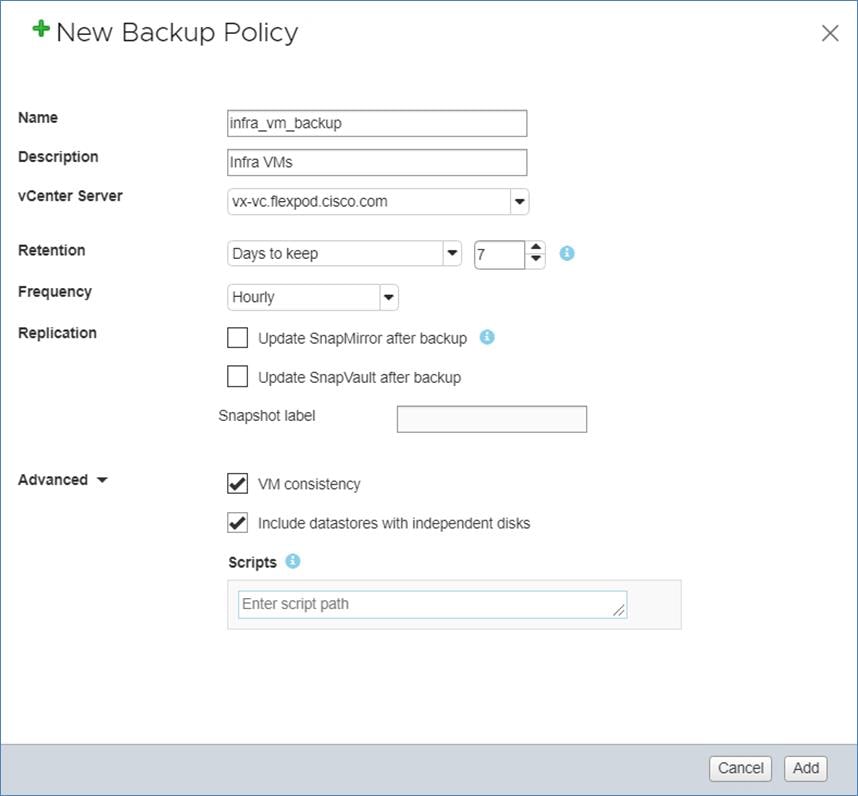
4. Create multiple policies as required for different sets of VMs or datastores.
Resource groups are groups of virtual machines or datastores that are backed up together. A backup policy is associated with the resource group to back up the virtual machines and retain a certain number of backups as defined in the policy.
To create resource groups, follow these steps:
1. In the left Navigator pane of the SnapCenter Plug-in for VMware vSphere, click Resource Groups and then click Create Resource Group. This is the easiest way to create a resource group. However, you can also create a resource group with one resource by performing one of the following steps:
2. To create a resource group for one virtual machine, click VMs and Templates, right-click a virtual machine, choose NetApp SnapCenter from the drop-down list, and then choose Create Resource Group from the secondary drop-down list.
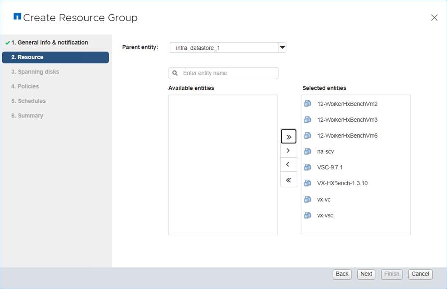
a. To create a resource group for one datastore, click Storage, right-click a datastore, choose NetApp SnapCenter from the drop-down list, and then choose Create Resource Group from the secondary drop-down list.
3. In the General Info & Notification page, enter the resource group name and complete the notification settings. Click Next.
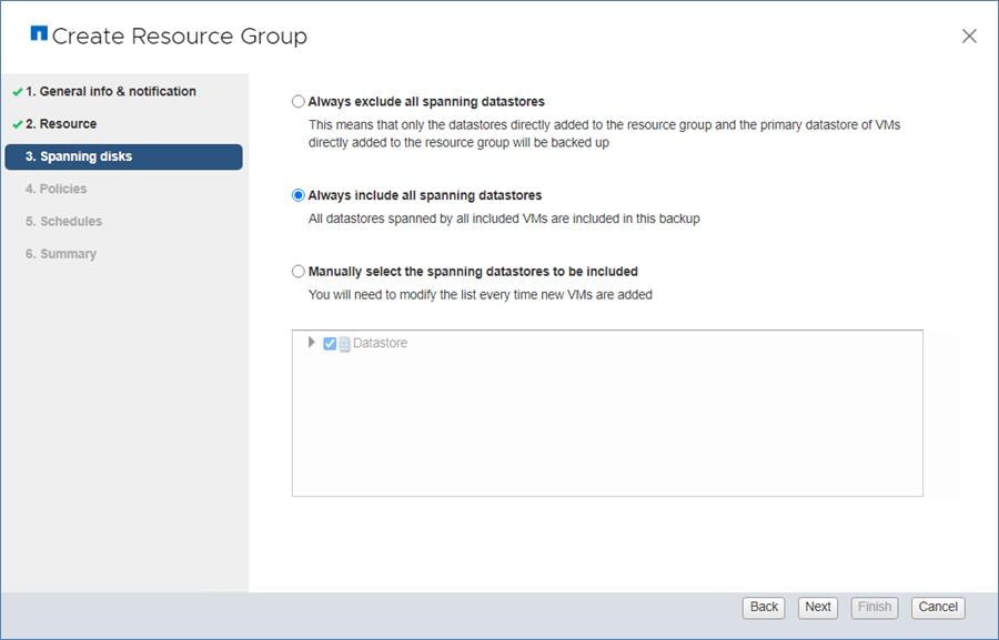
![]() Simplify the task of locating virtual machine and datastore snapshots by selecting the Custom snapshot format option and choose the desired label such as $ResourceGroup to have the resource group name appended to the snapshot name during snapshot operation.
Simplify the task of locating virtual machine and datastore snapshots by selecting the Custom snapshot format option and choose the desired label such as $ResourceGroup to have the resource group name appended to the snapshot name during snapshot operation.
4. Choose a datastore as the parent entity to create a resource group of virtual machines, and then choose the virtual machines from the available list. Click Next.

![]() All datastores can be backed up by selecting FlexPod-DC in the parent entity list box and selecting the datastore.
All datastores can be backed up by selecting FlexPod-DC in the parent entity list box and selecting the datastore.
5. From the Spanning Disks options, choose the Always include all spanning datastores option.

6. From the Policies tab, choose one of the previously created policies that you want to associate with the resource group and click Next.
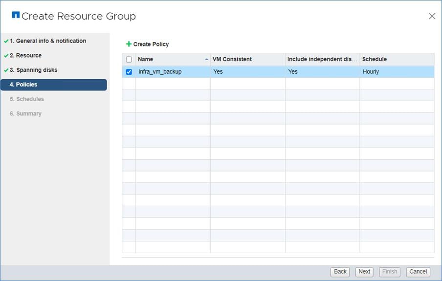
7. From the Schedules option, choose the schedule for each selected policy and click Next.
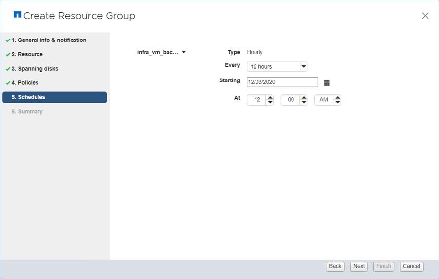
8. Review the summary and click Finish to complete the creation of the resource group.
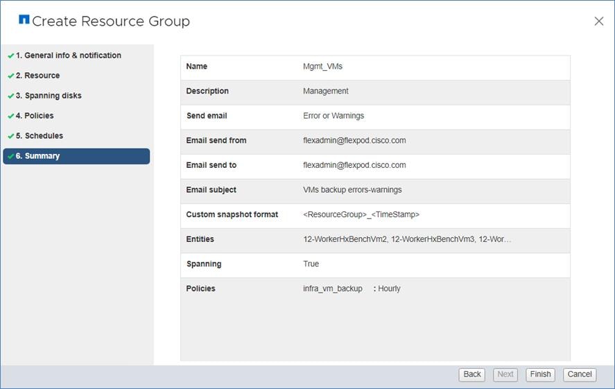
View Virtual Machine Backups from vCenter by Using SnapCenter Plug-In
Backups of the virtual machines included in the resource group occurs according to the schedule of the policies associated with the resource group. To view the backups associated with each schedule, follow these steps:
1. Navigate to the VMs and Templates tab.
2. Go to any virtual machine that is a member of a Resource Group and click the More Objects tab. Choose the Backups tab to view all the backups available for the virtual machine.
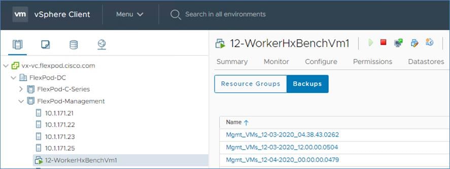
3. Navigate to the SnapCenter Plug-in for VMware vSphere and choose the Dashboard tab to view recent job activity, backup jobs and configuration details.
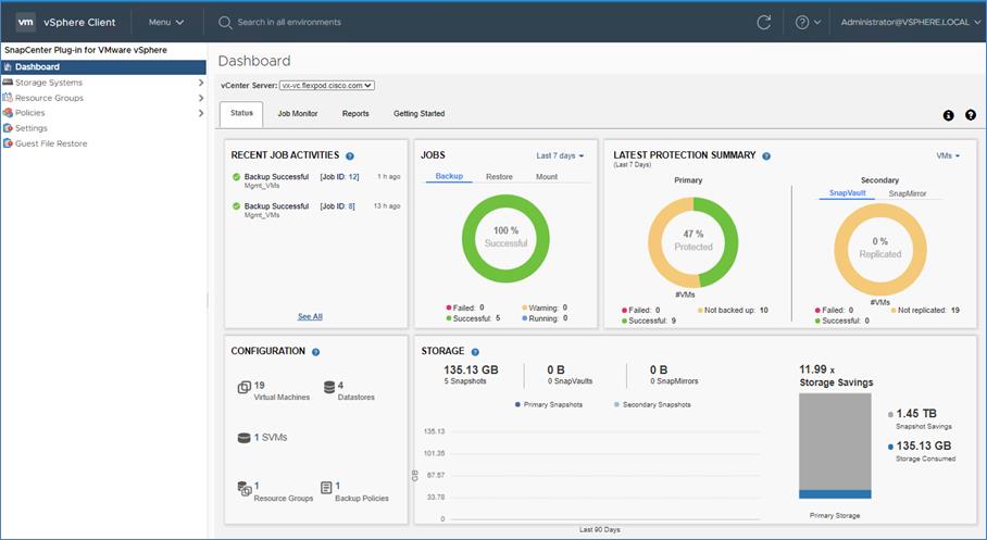
4. In the SnapCenter Plug-in for VMware vSphere, click Resource Groups and choose any resource group. In the right pane, the completed backups are displayed.
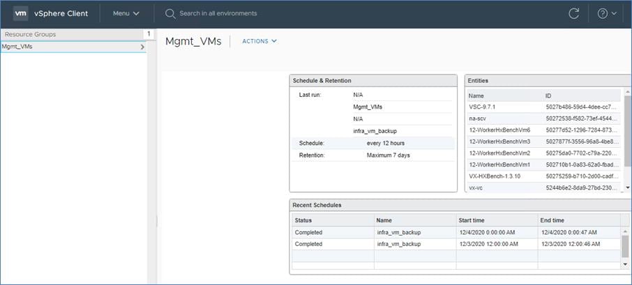
To create an on-demand backup for any resource group, follow these steps:
1. From the VMs and Templates tab, choose a virtual machine contained in the resource group where you want to create an on-demand backup.
2. Click the More Objects tab and choose the Resource Groups tab from the toolbar to display the list of resource groups.
3. Right-click the resource group and click Run Now to run the backup immediately.
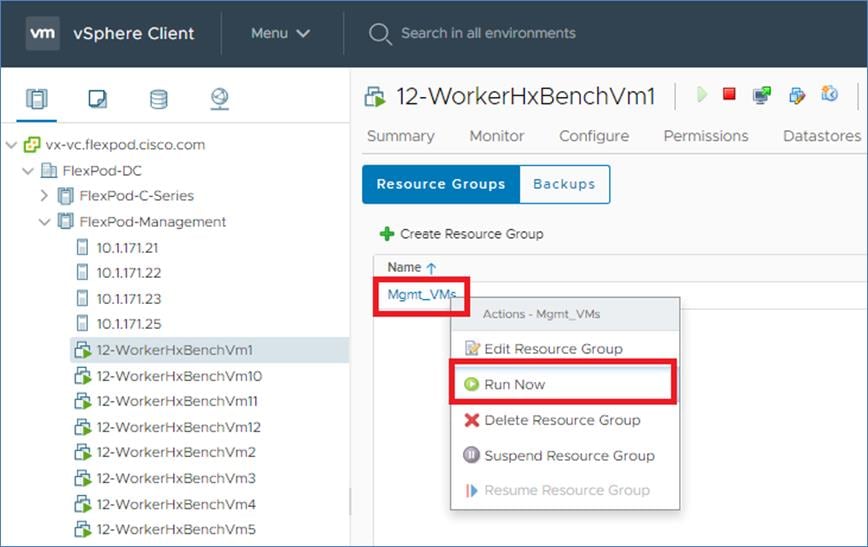
Restore from vCenter by Using SnapCenter Plug-In
To restore from vCenter by using the SnapCenter Plug-In, follow these steps:
![]() The Plug-in for VMware vSphere provides native backup, recovery, and cloning of virtualized applications.
The Plug-in for VMware vSphere provides native backup, recovery, and cloning of virtualized applications.
1. Navigate to VMs and Templates, choose a VM and right-click to access the context menu. Choose NetApp SnapCenter > Restore.
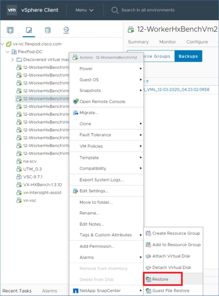
2. Choose a backup from which to restore. Click Next.
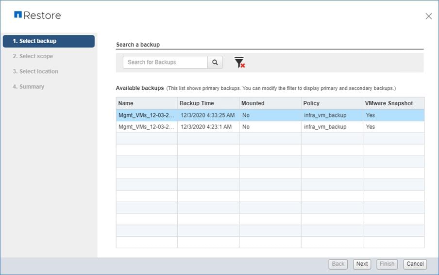
3. From the Restore Scope drop-down list:
a. Choose either "Entire virtual machine" to restore the virtual machine with all Virtual Machine Disks (VMDKs) or choose "Particular Virtual Disk" to restore the VMDK without affecting the virtual machine configuration and other VMDKs.
b. Choose the ESXi host that the VM should be restored to and check the box if you wish to restart the VM upon being restored. Click Next.
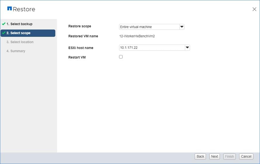
4. Choose the destination datastore and click Next.
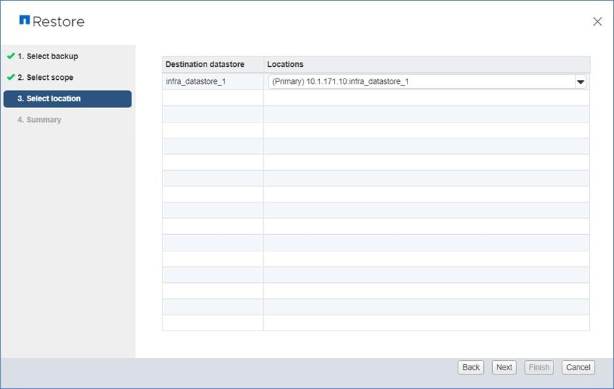
5. Review the Summary and click Finish to complete the restore process.
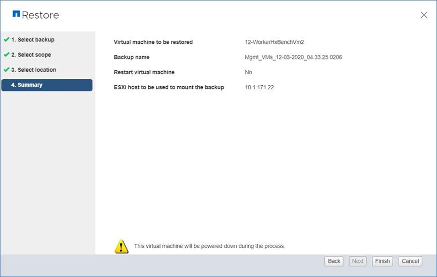
Active IQ Unified Manager 9.7P1
Active IQ Unified Manager (formerly OnCommand Unified Manager) enables you to monitor and manage the health and performance of your ONTAP storage systems from a single interface. Unified Manager provides a graphical interface that displays the capacity, availability, protection, and performance status of the monitored storage systems.
This section describes the steps to deploy NetApp Active IQ Unified Manager 9.7P1 as a virtual appliance. The following table lists the recommended configuration for the virtual machine to install and run Active IQ Unified Manager
Table 26. Virtual Machine Configuration
| Hardware Configuration |
Recommended Settings |
| RAM |
12 GB (minimum requirement 8 GB) |
| Processors |
4 CPUs/ vCPUs |
| CPU Cycle Capacity |
9572 MHz total (minimum requirement 9572 MHz) |
| Free Disk Space |
5 GB (thin provisioned) 152 GB (thick provisioned) |
![]() There is a limit to the number of nodes that a single instance of Active IQ Unified Manager can monitor before you need to install a second instance of Active IQ Unified Manager. See the Unified Manager Best Practices Guide (TR-4621) for more details.
There is a limit to the number of nodes that a single instance of Active IQ Unified Manager can monitor before you need to install a second instance of Active IQ Unified Manager. See the Unified Manager Best Practices Guide (TR-4621) for more details.
To install Unified Manager 9.7P1, follow these steps:
1. Download NetApp Active IQ Unified Manager for VMware vSphere .ova file from Netapp support site.
2. From the VMware VCenter, click the VMs and Templates Tab, then click In Actions> Deploy OVF Template.
3. Specify the location of the OVF Template and click Next.
4. On the Select a name and folder page, enter a unique name for the VM or vApp, and select a deployment location, and then click Next.
5. On the Select a compute resource page, select a resource where you want to run the deployed VM template, and click Next.
6. On the Review details page, verify the .ova template details and click Next.
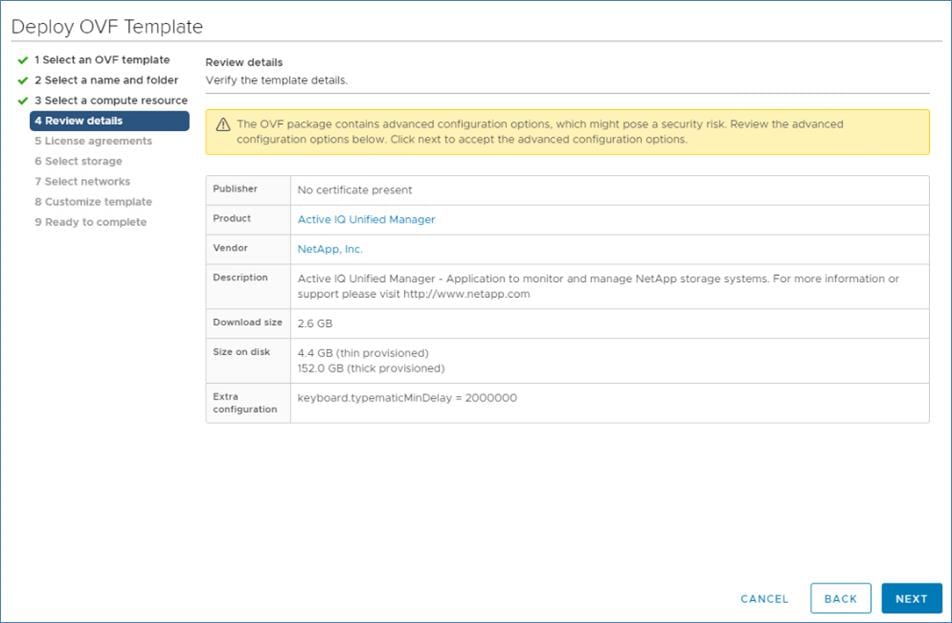
7. On the License agreements page, select the checkbox for I accept all license agreements.
8. On the Select storage page, define where and how to store the files for the deployed OVF template.
9. Select the disk format for the VMDKs
10. Select a VM Storage Policy.
11. Select a datastore to store the deployed OVA template.
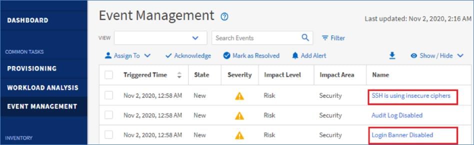
12. On the Select networks page, select a source network, and map it to a destination network and then click Next.
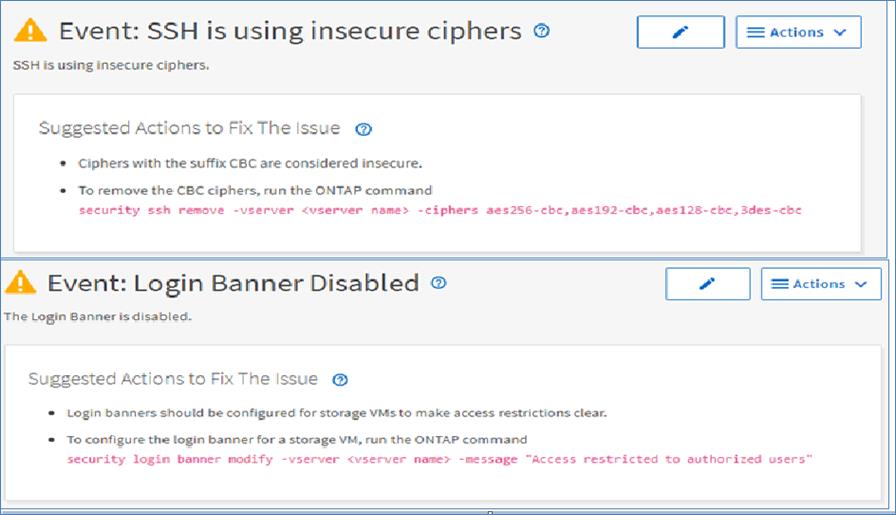
13. On the Customize template page, provide network details.
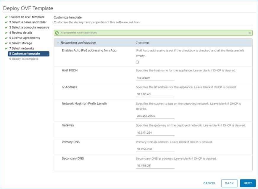
14. On the Ready to complete page, review the page and click Finish.
15. Navigate to the VM in the VMs and Templates Tab, then click the Summary tab, and then click the Power On box to start the virtual machine
16. While the virtual Machine is powering on, right-click the deployed virtual machine and then click Install VMware tools.
17. Click Mount in the Install VMware Tools dialog box and browse to the vmimages > tools-isoimages folder and choose linux.iso and click OK to proceed with installing VMware tools.
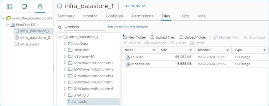
18. Open a console session to the Active IQ Unified Manager appliance and configure the time zone information when displayed.
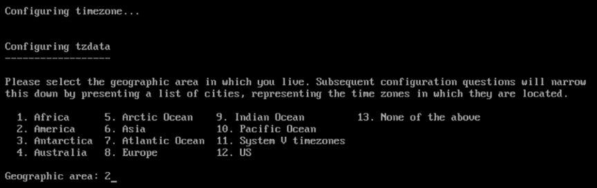
19. Create the maintenance user account when prompted by specifying a user account name and password.
![]() Store the maintenance user account and password in a secure location. It is required for the initial GUI login and to make any configuration changes to the appliance settings that may be needed in the future.
Store the maintenance user account and password in a secure location. It is required for the initial GUI login and to make any configuration changes to the appliance settings that may be needed in the future.
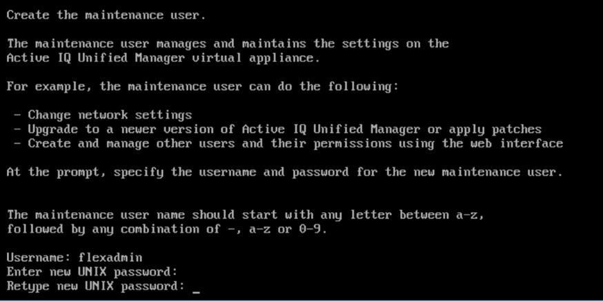
20. Log into NetApp Active IQ Unified Manager using the IP address or URL displayed on the deployment screen and the maintenance user credentials you created in the previous step.
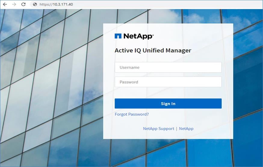
Configure Active IQ Unified Manager
To configure Active IQ Unified Manager and add a storage system for monitoring, follow these steps:
1. Login to the Active IQ Unified Manager.
2. Enter the email address that Unified Manager will use to send alerts, enter the mail server configuration, and the IP address or hostname of the NTP server. Click Continue and complete the AutoSupport configuration.

3. Configure AutoSupport for Unified Manager by clicking Agree and Continue.
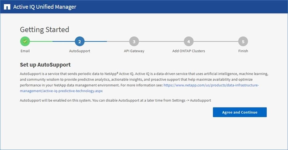
4. Configure AutoSupport for Unified Manager by clicking Continue.
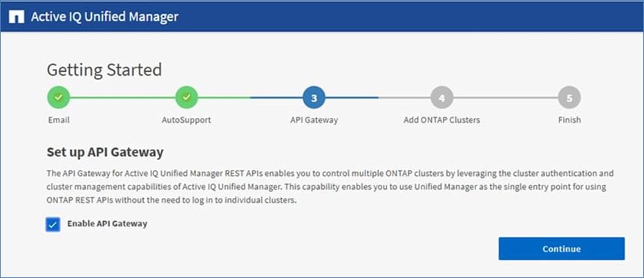
5. Enter the ONTAP cluster hostname or IP address and the admin login credentials then click Add.

6. A security prompt will be displayed to authorize the cluster certificate. Click Yes to trust the certificate.
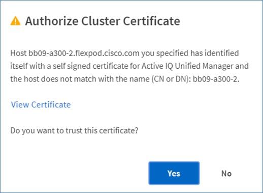
7. When prompted to trust the self-signed certificate from Active IQ Unified Manager, click Yes to finish and add the storage system.
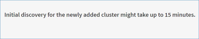
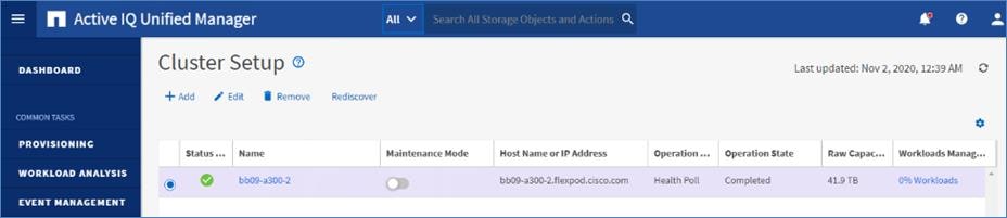
Add the vCenter Server to Active IQ Unified Manager
Active IQ Unified Manager provides visibility into vCenter and the virtual machines running inside the datastores backed by ONTAP storage. Virtual machines and storage are monitored to enable fast identification of performance issues within the various components of the virtual infrastructure stack.
Before adding vCenter into Active IQ Unified Manager the log level of the vCenter server must be changed by following these steps:
1. In the vSphere client navigate to VMs and Templates and choose the vCenter instance from the top of the object tree.
2. Click the Configure tab, expand the Settings, and choose General, Click EDIT
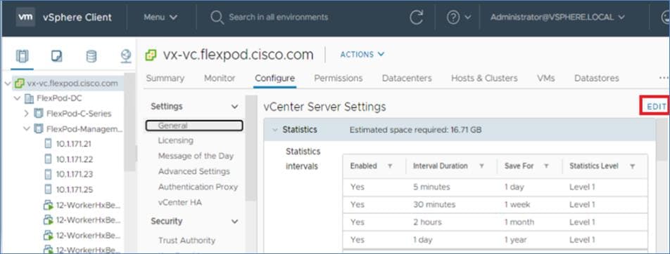
3. In the pop-up window under Statistics, locate the 5 minutes Interval Duration row and change the setting to Level 3 under the Statistics Level column. Click SAVE.
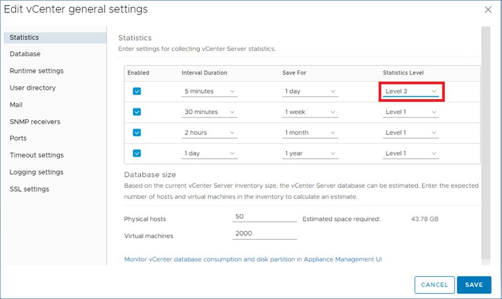
4. Return to Active IQ Unified Manager and navigate to the VMware section located under Inventory.
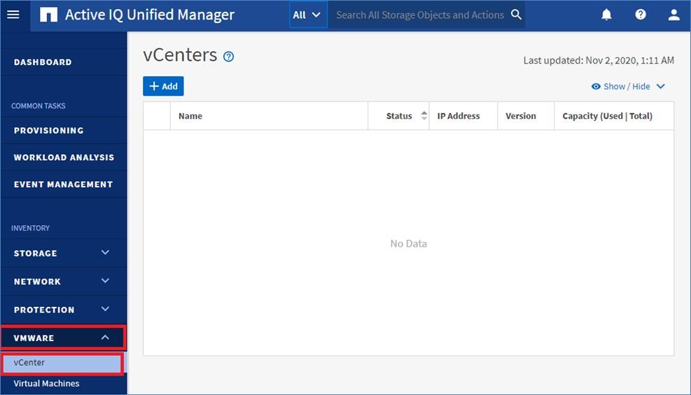
5. Expand the section and choose vCenter and click Add.
6. Enter the VMware vCenter server details and click Save.
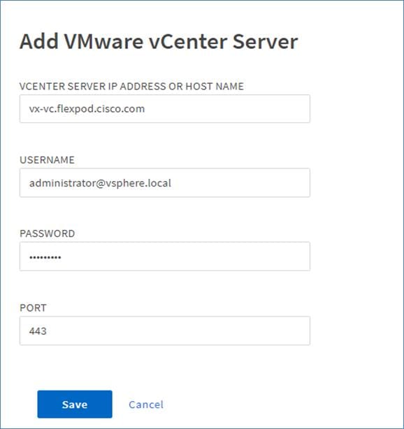
7. A dialog box will appear asking to authorize the certificate. Click Yes to trust the certificate and add the vCenter server.
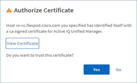
![]() It may take up to 15 minutes to discover the vCenter server. Performance data can take up to an hour after discovery to become available.
It may take up to 15 minutes to discover the vCenter server. Performance data can take up to an hour after discovery to become available.
View Virtual Machine Inventory
The virtual machine inventory is automatically added to Active IQ Unified Manager during discovery of the vCenter server. Virtual machines can be viewed in a hierarchical display detailing storage capacity, IOPS and latency for each component in the virtual infrastructure to troubleshoot the source of any performance related issues.
To review the virtual machine topology and statics, follow these steps:
1. Navigate to the VMware section located under Inventory, expand the section, and click Virtual Machines.
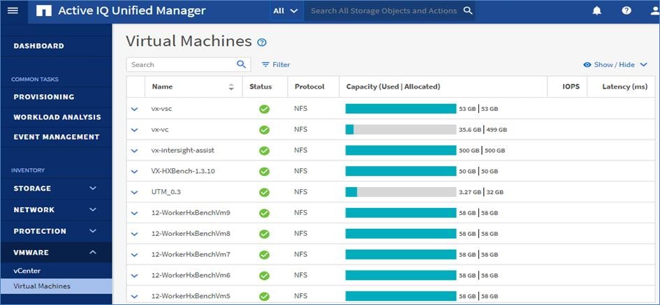
2. Choose a VM and click the blue caret to expose the topology view. Review the compute, network, and storage components and their associated IOPS and latency statistics.
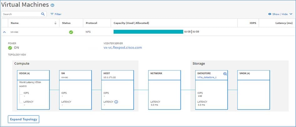
3. Click Expand Topology to see the entire hierarchy of the virtual machine and its virtual disks as it is connected through the virtual infrastructure stack. The VM components are mapped from vSphere and compute through the network to the storage.
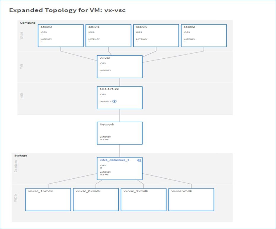
Review Security Compliance with Active IQ Unified Manager
Active IQ Unified Manager identifies issues and makes recommendations to improve the security posture of ONTAP. Active IQ Unified Manager evaluates ONTAP storage based on recommendations made in the Security Hardening Guide for ONTAP 9. Items are identified according to their level of compliance with the recommendations. All events identified do not inherently apply to all environments, for example, FIPS compliance. Review the Security Hardening Guide for NetApp ONTAP 9 (TR-4569) for additional information and recommendations for securing ONTAP 9.
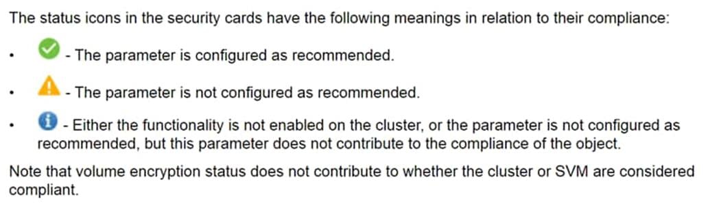
To identify security events in Active IQ Unified Manager, follow these steps:
1. Navigate to the URL of the Active IQ Unified Manager installation and login.
2. Choose the Dashboard from the left menu bar in Active IQ Unified Manager.
3. Select the individual cluster under Dashboard.
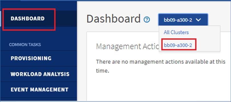
4. Locate the Security card and note the compliance level of the cluster and SVM. Click the blue arrow to expand the findings.
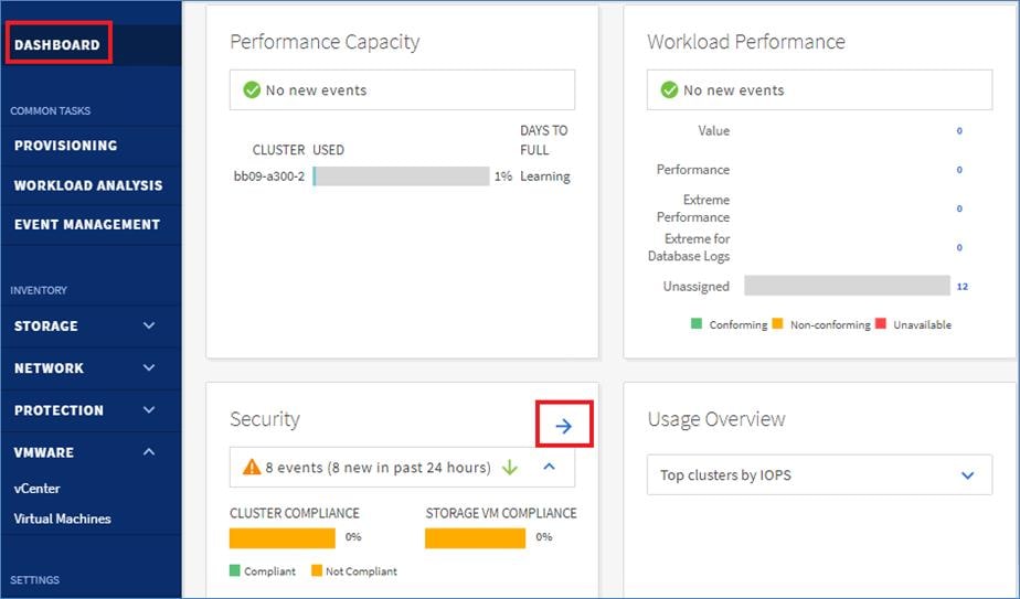
5. From the drop-down list choose View All.
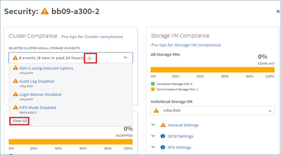
6. Choose an event from the list and click the name of the event to view the remediation steps.

7. Remediate the risk if desired and perform the suggested actions to fix the issue.

Remediate Security Compliance Findings
Active IQ identifies several security compliance risks after installation that can be immediately corrected to improve the security posture of ONTAP.
Correct Cluster Risks
To correct cluster risks, follow these steps:
1. Remove insecure SSH ciphers from the cluster administrative SVM:
security ssh remove -vserver <clus-adm-svm> -ciphers aes256-cbc,aes192-cbc,aes128-cbc,3des-cbc
2. Enable the login banner on the cluster:
security login banner modify -vserver <clustername> -message "Access restricted to authorized users"
Correct Infrastructure Storage VM Risks
To correct infrastructure storage VM risks, follow these steps:
1. Remove insecure SSH ciphers from the cluster administrative SVM:
security ssh remove -vserver <infra-data-svm> -ciphers aes256-cbc,aes192-cbc,aes128-cbc,3des-cbc
2. Enable the login banner on the cluster:
security login banner modify -vserver <infra-data-svm> -message "Access restricted to authorized users"
NetApp Active IQ is a data-driven service that leverages artificial intelligence and machine learning to provide analytics and actionable intelligence for ONTAP storage systems. Active IQ uses AutoSupport data to deliver proactive guidance and best practices recommendations to optimize storage performance and minimize risk.
Additional Active IQ documentation is available on the Active IQ Documentation Resources web page.
Active IQ is automatically enabled when you configure AutoSupport on the ONTAP storage controllers. To get started with Active IQ follow these steps:
1. Obtain the controller serial numbers from your ONTAP system with the following command:
system node show -fields serialnumber
2. Navigate to the Active IQ portal at https://activeiq.netapp.com/
3. Login with you NetApp support account ID.
4. At the welcome screen enter the cluster name or one of controller serial numbers in the search box. Active IQ will automatically begin searching for the cluster and display results below.
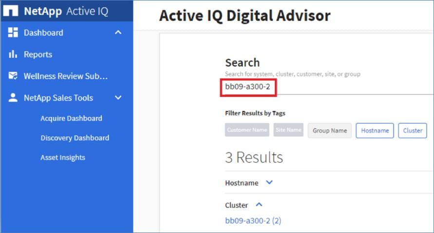
5. Choose the cluster name to launch the main dashboard.
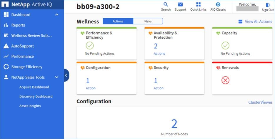
Create Active IQ Digital Advisor Dashboard
The system level dashboard is the default view for systems in Active IQ. To create a dashboard, follow these steps:
1. On the Create Dashboard page, click here to create a dashboard.
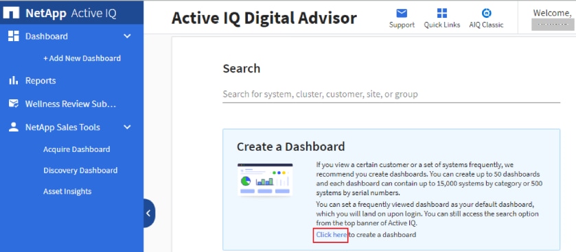
2. Click Create Watchlist and enter a name for the watchlist.
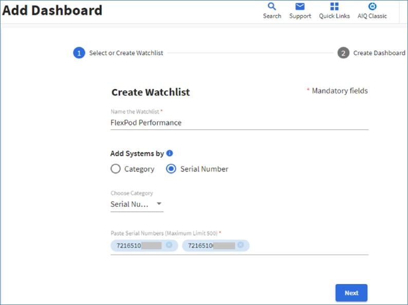
3. Choose the radio button to add systems by serial number and enter the cluster serial numbers to the watchlist.
4. Check the box for Make this my default dashboard and click Create.
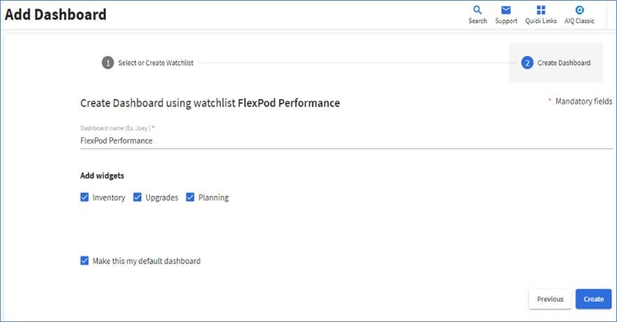
5. Review the enhanced dashboard including the Wellness Score and any recommended actions or risks.
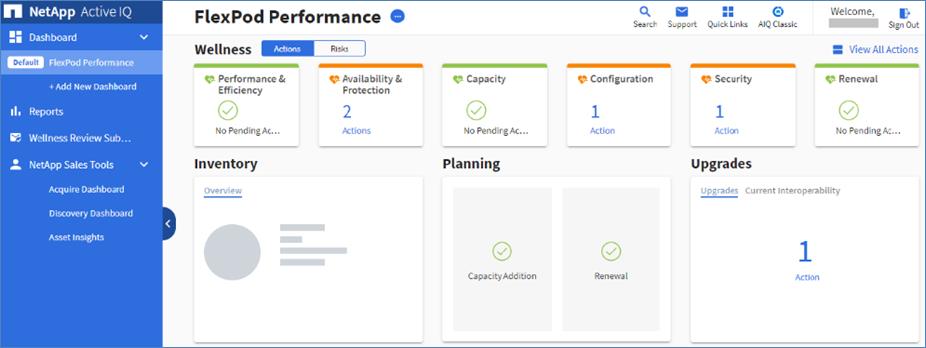
6. Switch between the Actions and Risks tabs to view the risks broken down by category or a list of all risks with their impact and links to corrective actions.
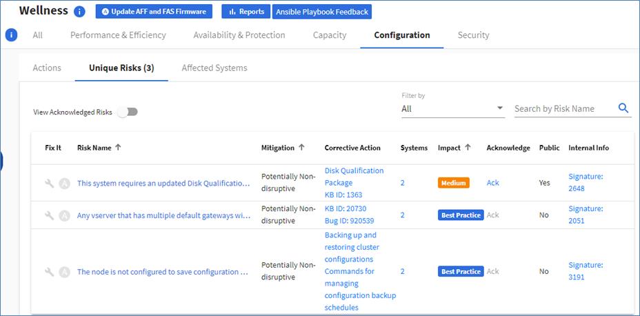
7. Click the link in the Corrective Action column to read the bug information or knowledge base article about how to remediate the risk.
![]() Additional tutorials and video walk-throughs of Active IQ features can be viewed on the Active IQ documentation web page.
Additional tutorials and video walk-throughs of Active IQ features can be viewed on the Active IQ documentation web page.
Cisco Intersight
Cisco Intersight™ is a management platform delivered as a service with embedded analytics for your Cisco and third-party IT infrastructure. This platform offers an intelligent level of management that enables IT organizations to analyze, simplify, and automate their environments in more advanced ways than the prior generations of tools. Cisco Intersight provides an integrated and intuitive management experience for resources in the traditional data center and at the edge. With flexible deployment options to address complex security needs, getting started with Intersight is quick and easy.
Cisco Intersight offers flexible deployment either as Software as a Service (SaaS) on Intersight.com or running on your premises as Cisco Intersight Virtual Appliance. The virtual appliance provides the benefits of Cisco Intersight while allowing more flexibility for those with additional data locality and security requirements. The remainder of this section details Intersight deployment as SaaS on Intersight.com. To learn more about the virtual appliance, see the Cisco Intersight Virtual Appliance Getting Started Guide.
To configure Cisco Intersight, follow these steps:
1. If you do not already have a Cisco Intersight account, to claim your Cisco UCS system into a new account on Cisco Intersight, connect to https://Intersight.com.
2. Click Create an account.
3. Click Continue. Complete the Sign in process with your Cisco ID.
4. Read the Offer Description carefully and accept it. Click Next.
5. Enter an Account Name, Device ID, and Claim Code. The Device ID and Claim Code can be obtained by connecting to Cisco UCS Manager and selecting Admin > All > Device Connector. The Device ID and Claim Code are on the right. Click Claim.
6. Click Create. After the account has been created, click Log me in to log into Cisco Intersight.
7. To claim your Cisco UCS system into an existing Intersight account, log into the account at https://Intersight.com. Choose Administration > Devices. Click Claim a New Device. Under Direct Claim, fill in the Device ID and Claim Code. The Device ID and Claim Code can be obtained by connecting to Cisco UCS Manager and selecting Admin > All > Device Connector. The Device ID and Claim Code are on the right.
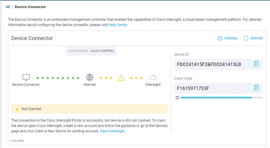
8. From the Cisco Intersight window, click ![]() and then click Licensing. If this is a new account, all servers connected to the UCS Domain will appear under the Base license Tier. If you have purchased Cisco Intersight licenses and have them in your Cisco Smart Account, click Register and follow the prompts to register this Cisco Intersight account to your Cisco Smart Account. Cisco Intersight also offers a one-time 90-day trial of Premier licensing for new accounts. Click Start Trial and then Start to begin this evaluation. The remainder of this section will assume Premier licensing.
and then click Licensing. If this is a new account, all servers connected to the UCS Domain will appear under the Base license Tier. If you have purchased Cisco Intersight licenses and have them in your Cisco Smart Account, click Register and follow the prompts to register this Cisco Intersight account to your Cisco Smart Account. Cisco Intersight also offers a one-time 90-day trial of Premier licensing for new accounts. Click Start Trial and then Start to begin this evaluation. The remainder of this section will assume Premier licensing.
9. From the Licensing Window, click Set Default Tier. From the drop-down list choose Premier for Tier and click Set.
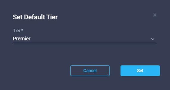
10. To set all Cisco UCS Servers to Premier licensing, click Servers. Click  to the left of the Name heading to choose all servers. Click
 ![]() above the headings and click Set License Tier. From the drop-down list choose Premier for the Tier and click Set License Tier.
above the headings and click Set License Tier. From the drop-down list choose Premier for the Tier and click Set License Tier.
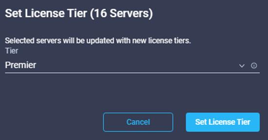
11. Click Refresh to refresh the Intersight window with Premier, Advantage, and Essentials features added.
12. Click ![]() in the Intersight window and click Take a Site Tour. Follow the prompts for a tour of Cisco Intersight.
in the Intersight window and click Take a Site Tour. Follow the prompts for a tour of Cisco Intersight.
13. The Essentials tier of Cisco Intersight includes a Cisco driver check against the Cisco Hardware Compatibility List (HCL). In the Servers list, choose one of the servers in your VMware FlexPod-Management cluster by clicking the server name. Review the detailed General and Inventory information for the server. Click the HCL tab. Review the server information, the version of VMware ESXi, and the Cisco VIC driver versions and RAID card if present.
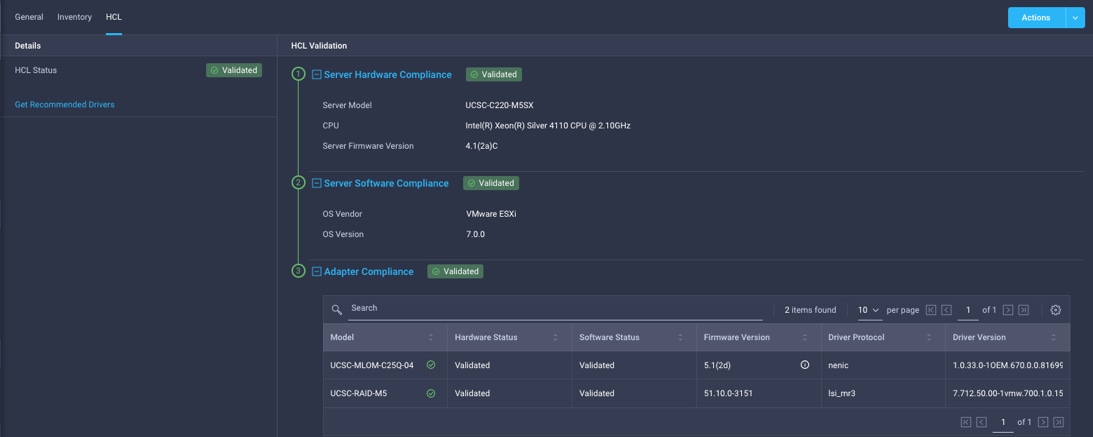
14. Using the Intersight Assist personality of the Cisco Intersight Virtual Appliance VMware vCenter currently can be monitored (Advantage Licensing Tier) and configured (Premier Licensing Tier Tech Preview not to be used in production environments). To install Intersight Assist from an Open Virtual Appliance (OVA) in your VMware FlexPod-Management Cluster, first download the latest release of the OVA from https://software.cisco.com/download/home/286319499/type/286323047/release/1.0.9-148.
15. Refer to https://www.cisco.com/c/en/us/td/docs/unified_computing/Intersight/cisco-intersight-assist-getting-started-guide/m-installing-cisco-intersight-assist.html and set up the DNS entries for the Intersight Assist hostname as specified under Before you begin.
16. From Hosts and Clusters in the VMware vCenter HTML5 client, right-click the FlexPod-Management cluster and click Deploy OVF Template.
17. Specify a URL or either browse to the intersight-virtual-appliance-1.0.9-148.ova or latest release file. Click NEXT.
18. Name the Intersight Assist VM and choose the location. Click NEXT.
19. Choose the FlexPod-Management cluster and click NEXT.
20. Review details and click NEXT.
21. Choose a deployment configuration (Tiny recommended) and click NEXT.
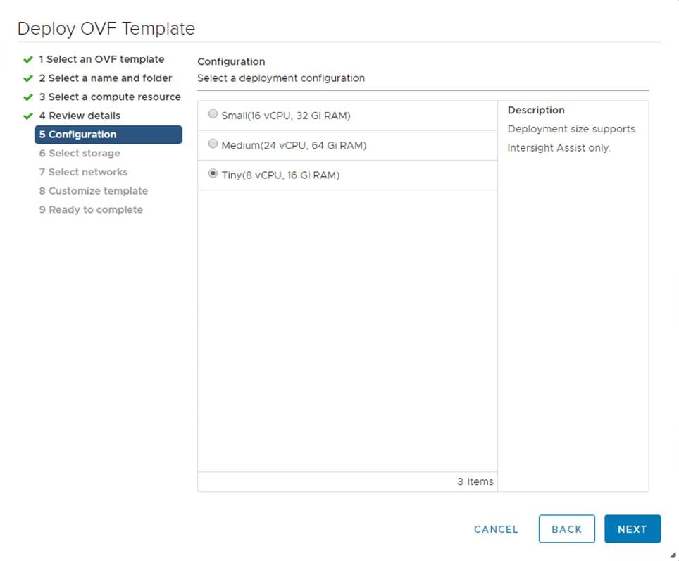
22. Choose infra_datastore_1 for storage and choose the Thin Provision virtual disk format. Click NEXT.
23. Choose Common-Services for the VM Network. Click NEXT.
24. Fill in all values to customize the template. Click NEXT.
25. Review the deployment information and click FINISH to deploy the appliance.
26. Once the OVA deployment is complete, right-click the Intersight Assist VM and click Edit Settings.
27. Expand CPU and adjust the Cores per Socket so that the number of Sockets matches your server CPU configuration. In this example 2 Sockets are shown. Click OK.
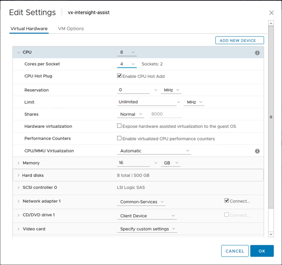
28. Right-click the Intersight Assist VM and choose Open Remote Console.
29. Click ![]() to power on the VM.
to power on the VM.
30. When you see the login prompt, close the Remote Console, and connect to https://<intersight-assist-fqdn>.
![]() It may take a few minutes for https://<intersight-assist-fqdn> to respond.
It may take a few minutes for https://<intersight-assist-fqdn> to respond.
31. Navigate the security prompts and select Intersight Assist. Click Proceed.
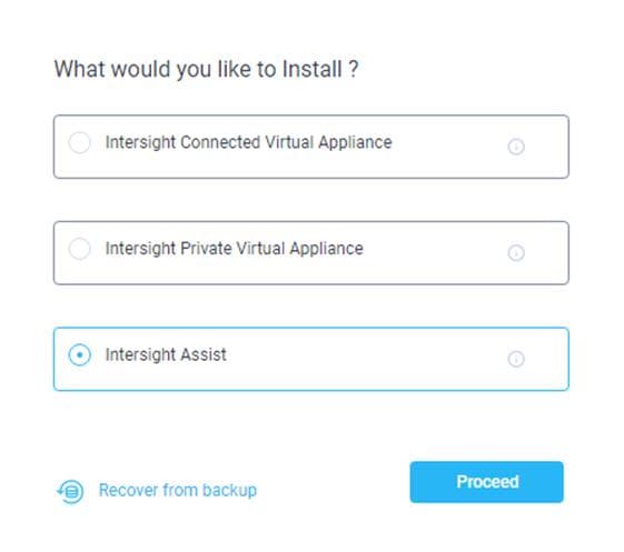
32. From Cisco Intersight, click ADMIN > Devices. Click Claim a New Device. Copy and paste the Device ID and Claim Code shown in the Intersight Assist web interface to the Cisco Intersight Device Claim Direct Claim window. In Cisco Intersight, click Claim. Intersight Assist will now appear as a claimed device.
33. In the Intersight Assist web interface, reload if necessary to reflect the connection, then click Continue.
34. The Intersight Assist software will now be downloaded and installed into the Intersight Assist VM. This can take up to an hour to complete.
35. When the software download is complete, an Intersight Assist login screen will appear. Log into Intersight Assist with the admin@local user and the password supplied in the OVA installation. Check the Intersight Assist status and log out of Intersight Assist.
36. To claim the vCenter, from Cisco Intersight, click ADMIN > Devices. Click Claim a New Device. In the Device Claim window, choose Claim Through Intersight Assist. Fill in the vCenter information and click Claim.
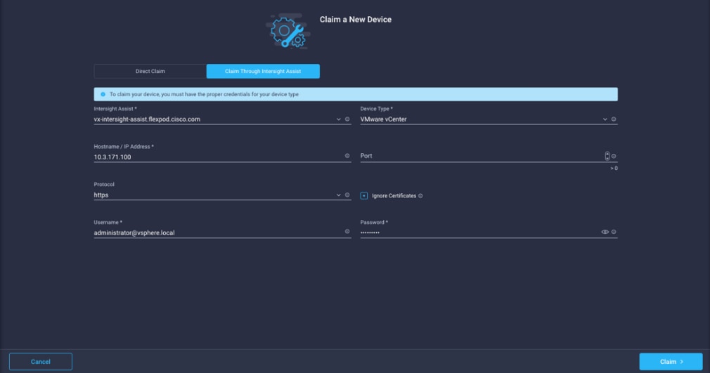
37. After a few minutes, the VMware vCenter will appear in the Devices list. It also can be viewed by clicking Intersight Assist in the Devices list.
38. Detailed information obtained from the vCenter can now be viewed by clicking Virtualization from the menu.
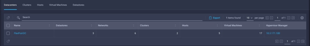
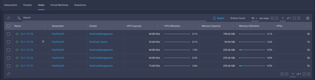
Solution Deployment - Sample Tenant Provisioning
Provision a Sample Application Tenant
This section describes a sample procedure for provisioning an application tenant. The procedure here refers to previous sections of this document and can be used as a guide and modified as needed when provisioning an application tenant.
Plan your application tenant and determine what storage protocols will be provided in the tenant. In the architecture covered in this document, NFS, iSCSI, and CIFS/SMB can be provided to the tenant. Also, plan what network VLANs the tenant will use. It is recommended to have a VLAN for SVM management traffic. The tenant application VLAN can be used for SVM management. One or two VLANs (iSCSI needs two if VMware RDM LUNs or iSCSI datastores will be provisioned) are also needed for each storage protocol used. If the infrastructure NFS VLAN will be used in the tenant, consider migrating the infrastructure NFS VMkernel port on each host to the vDS to take advantage of Ethernet adapter policy queuing.
In the DCNM, create the necessary application and application storage VLANs and enable them on the access-layer vPC connections to Cisco UCS and NetApp storage. Also, for some networks, the fabric can be used for strictly Layer 2 forwarding (for example, storage networks) and for others the VXLAN fabric can serve as the default gateway to reach other networks connected to the same shared fabric or for connectivity outside the fabric. See Solution Deployment – Network section for more details on provisioning the network fabric to support the Application Tenant and associated networks.
Once the fabric is provisioned, configure the VLANs on Cisco UCS and NetApp storage systems and enable them on the uplinks to the VXLAN fabric.
In the storage cluster:
● Create a broadcast domain with MTU 1500 for the tenant SVM management interface. Create a broadcast domain with MTU 9000 for each tenant storage protocol.
● Create VLAN interface ports on the node interface group on each node for tenant SVM management (VM VLAN) and for the VLAN for each storage protocol. Add these VLAN ports to the appropriate broadcast domains.
● Create the tenant SVM and follow all procedures in that section.
● Create Load-Sharing Mirrors for the tenant SVM.
● Create the iSCSI service for the tenant SVM if iSCSI is being deployed in this tenant.
● Optionally, create a self-signed security certificate for the tenant SVM.
● Configure NFSv3 for the tenant SVM.
● Create a VM datastore volume in the tenant SVM.
● For iSCSI configure four iSCSI LIFs in the tenant SVM on the iSCSI VLAN interfaces.
● Create one NFS LIF in the tenant SVM on each storage node.
● Create a boot LUN in the esxi_boot volume in the Infra-SVM for each tenant VMware ESXi host.
● Add the tenant SVM Administrator, SVM management LIF on the SVM management VLAN port, and default route for the SVM.
In Cisco UCS, one method of tenant setup is to dedicate a VMware ESXi cluster and set of UCS servers to each tenant. Service profiles will be generated for at least two tenant ESXi hosts. These hosts can boot from LUNs from the esxi_boot volume in the Infra-SVM but will also have access to iSCSI storage in the tenant SVM.
● Create a Server Pool for the tenant ESXi host servers.
● Create all tenant VLANs in the LAN Cloud.
● Add the tenant VLANs to the vDS vNIC templates.
● Generate service profiles from the service profile template with the vMedia policy for the tenant ESXi hosts. Remember to bind these service profiles to the service profile template without the vMedia policy after VMware ESXi installation.
In the storage cluster:
● Create igroups for the tenant ESXi hosts in both the Infra-SVM and tenant SVM. Also, create an igroup in the tenant SVM that includes the IQNs for all tenant ESXi hosts to support shared storage from the tenant SVM.
● In Infra-SVM, map the boot LUNs created earlier to the tenant ESXi hosts. Tenant iSCSI storage can be created later using NetApp VSC.
● Install and configure VMware ESXi on all tenant host servers. Optionally, if needed then infra_datastore_1/_2 datastores can be mapped to the tenant hosts.
● In VMware vCenter, create a cluster for the tenant ESXi hosts. Add the hosts to the cluster.
● Using the vCenter HTML5 Client, add the tenant hosts to vDS0 or create a tenant vDS (using the vDS0 vNICs) and add the hosts to it. In vDS0 or the tenant vDS, add port-profiles for the tenant VLANs.
● Back in vCenter, add in any necessary VMkernel ports for storage interfaces remembering to set the MTU correctly on these interfaces. Mount the tenant NFS datastore on the tenant cluster if one was created. Tenant iSCSI VMkernel ports can be created on the vDS with the port groups pinned to the appropriate fabric. Add the tenant iSCSI LIF IP addresses as Dynamic Targets on the VMware ESXi hosts in the vCenter HTML5 Client.
● Using the NetApp VSC plugin to the vCenter HTML5 Client, set recommended values for all tenant ESXi hosts. Ensure the NetApp NFS Plug-in for VMware VAAI is installed on all tenant hosts and reboot each host.
You can now begin provisioning virtual machines on the tenant cluster. The NetApp VSC plugin can be used to provision iSCSI and NFS datastores. Optionally, use NetApp SnapCenter to provision backups of tenant virtual machines.
The leaf and spine configurations deployed in the environment by DCNM are provided below. The FlexPod compute and storage infrastructure connect to the Leaf switches included in this section. The configuration for the optional Border Leaf switches are not included here.
Leaf A
version 9.3(5) Bios:version 05.42
switchname AA01-9336C-FX2-1
vdc AA01-9336C-FX2-1 id 1
limit-resource vlan minimum 16 maximum 4094
limit-resource vrf minimum 2 maximum 4096
limit-resource port-channel minimum 0 maximum 511
limit-resource u4route-mem minimum 248 maximum 248
limit-resource u6route-mem minimum 96 maximum 96
limit-resource m4route-mem minimum 58 maximum 58
limit-resource m6route-mem minimum 8 maximum 8
limit-resource vni_bd minimum 4096 maximum 4096
feature nxapi
cfs ipv4 distribute
nv overlay evpn
feature ospf
feature bgp
feature pim
feature interface-vlan
feature vn-segment-vlan-based
feature lacp
feature dhcp
feature vpc
feature lldp
feature nv overlay
feature ngoam
username admin password 5 $5$LL7Z.BYy$U6AAWL6OvWLdvJ6SB5Hul.UCZ2I5EskdSKoubMKKvm
1 role network-admin
ip domain-lookup
copp profile strict
configure profile FPV-Foundation_VRF
vlan 3500
name FPV_Foundation_VRF_VLAN
vn-segment 30000
interface Vlan3500
description FPV_Foundation_VRF_Interface
vrf member fpv-foundation_vrf
ip forward
ipv6 address use-link-local-only
no ip redirects
no ipv6 redirects
mtu 9216
no shutdown
vrf context fpv-foundation_vrf
description FPV_Foundation_VRF
vni 30000
rd auto
address-family ipv4 unicast
route-target both auto
route-target both auto evpn
address-family ipv6 unicast
route-target both auto
route-target both auto evpn
router bgp 65001
vrf fpv-foundation_vrf
address-family ipv4 unicast
advertise l2vpn evpn
redistribute direct route-map fabric-rmap-redist-subnet
maximum-paths ibgp 2
address-family ipv6 unicast
advertise l2vpn evpn
redistribute direct route-map fabric-rmap-redist-subnet
maximum-paths ibgp 2
interface nve1
member vni 30000 associate-vrf
configure terminal
configure profile FPV-iSCSI-A_Network
vlan 3010
vn-segment 20000
name FPV-iSCSI-A_VLAN
interface nve1
member vni 20000
mcast-group 239.1.1.0
evpn
vni 20000 l2
rd auto
route-target import auto
route-target export auto
configure terminal
configure profile FPV-iSCSI-B_Network
vlan 3020
vn-segment 20001
name FPV-iSCSI-B_VLAN
interface nve1
member vni 20001
mcast-group 239.1.1.0
evpn
vni 20001 l2
rd auto
route-target import auto
route-target export auto
configure terminal
configure profile FPV-InfraNFS_Network
vlan 3050
vn-segment 20002
name FPV-InfraNFS_VLAN
interface nve1
member vni 20002
mcast-group 239.1.1.0
evpn
vni 20002 l2
rd auto
route-target import auto
route-target export auto
configure terminal
configure profile FPV-InBand-SiteA_Network
vlan 122
vn-segment 20003
name FPV-InBand-SiteA_VLAN
interface Vlan122
description FPV-InBand-SiteA_Interface
vrf member fpv-foundation_vrf
no ip redirects
no ipv6 redirects
ip address 10.1.171.254/24 tag 12345
mtu 9216
fabric forwarding mode anycast-gateway
no shutdown
interface nve1
member vni 20003
mcast-group 239.1.1.0
suppress-arp
evpn
vni 20003 l2
rd auto
route-target import auto
route-target export auto
configure terminal
configure profile FPV-vMotion_Network
vlan 3000
vn-segment 20004
name FPV-vMotion_VLAN
interface nve1
member vni 20004
mcast-group 239.1.1.0
evpn
vni 20004 l2
rd auto
route-target import auto
route-target export auto
configure terminal
configure profile FPV-CommonServices_Network
vlan 322
vn-segment 20005
name FPV-CommonServices_VLAN
interface Vlan322
description FPV-CommonServices_Interface
vrf member fpv-foundation_vrf
no ip redirects
no ipv6 redirects
ip address 10.3.171.254/24 tag 12345
mtu 9216
fabric forwarding mode anycast-gateway
no shutdown
interface nve1
member vni 20005
mcast-group 239.1.1.0
suppress-arp
evpn
vni 20005 l2
rd auto
route-target import auto
route-target export auto
configure terminal
configure profile FPV-Application_VRF
vlan 3501
name FPV-Application_VRF_VLAN
vn-segment 30001
interface Vlan3501
description FPV-Application_VRF_Interface
vrf member fpv-application_vrf
ip forward
ipv6 address use-link-local-only
no ip redirects
no ipv6 redirects
mtu 9216
no shutdown
vrf context fpv-application_vrf
description FPV-Application_VRF
vni 30001
rd auto
address-family ipv4 unicast
route-target both auto
route-target both auto evpn
address-family ipv6 unicast
route-target both auto
route-target both auto evpn
router bgp 65001
vrf fpv-application_vrf
address-family ipv4 unicast
advertise l2vpn evpn
redistribute direct route-map fabric-rmap-redist-subnet
maximum-paths ibgp 2
address-family ipv6 unicast
advertise l2vpn evpn
redistribute direct route-map fabric-rmap-redist-subnet
maximum-paths ibgp 2
interface nve1
member vni 30001 associate-vrf
configure terminal
configure profile FPV-App-1_Network
vlan 1001
vn-segment 21001
name FPV-App-1_VLAN
interface Vlan1001
description FPV-App-1_Interface
vrf member fpv-application_vrf
no ip redirects
no ipv6 redirects
ip address 172.22.1.254/24 tag 12345
mtu 9216
fabric forwarding mode anycast-gateway
no shutdown
interface nve1
member vni 21001
mcast-group 239.1.1.0
suppress-arp
evpn
vni 21001 l2
rd auto
route-target import auto
route-target export auto
configure terminal
configure profile FPV-App-2_Network
vlan 1002
vn-segment 21002
name FPV-App-2_VLAN
interface Vlan1002
description FPV-App-2_Interface
vrf member fpv-application_vrf
no ip redirects
no ipv6 redirects
ip address 172.22.2.254/24 tag 12345
mtu 9216
fabric forwarding mode anycast-gateway
no shutdown
interface nve1
member vni 21002
mcast-group 239.1.1.0
suppress-arp
evpn
vni 21002 l2
rd auto
route-target import auto
route-target export auto
configure terminal
configure profile FPV-App-3_Network
vlan 1003
vn-segment 21003
name FPV-App-3_VLAN
interface Vlan1003
description FPV-App-3_Interface
vrf member fpv-application_vrf
no ip redirects
no ipv6 redirects
ip address 172.22.3.254/24 tag 12345
fabric forwarding mode anycast-gateway
no shutdown
interface nve1
member vni 21003
mcast-group 239.1.1.0
suppress-arp
evpn
vni 21003 l2
rd auto
route-target import auto
route-target export auto
configure terminal
snmp-server user admin network-admin auth md5 0xba043903263cde0a9b23f130b0aabfa0
priv 0xba043903263cde0a9b23f130b0aabfa0 localizedkey
snmp-server host 172.26.163.142 traps version 2c public udp-port 2162
rmon event 1 log trap public description FATAL(1) owner PMON@FATAL
rmon event 2 log trap public description CRITICAL(2) owner PMON@CRITICAL
rmon event 3 log trap public description ERROR(3) owner PMON@ERROR
rmon event 4 log trap public description WARNING(4) owner PMON@WARNING
rmon event 5 log trap public description INFORMATION(5) owner PMON@INFO
ntp server 172.26.163.254 use-vrf management
ntp server 172.26.164.254 use-vrf management
fabric forwarding anycast-gateway-mac 2020.0000.00aa
ipv6 switch-packets lla
ip pim rp-address 10.11.254.1 group-list 239.1.1.0/25
ip pim ssm range 232.0.0.0/8
vlan 1,122,322,1001-1003,3000,3010,3020,3050,3500-3501
route-map fabric-rmap-redist-subnet permit 10
match tag 12345
service dhcp
ip dhcp relay
ip dhcp relay information option
ip dhcp relay information option vpn
ipv6 dhcp relay
vrf context management
ip route 0.0.0.0/0 172.26.163.254
hardware access-list tcam region ing-racl 1792
hardware access-list tcam region ing-flow-redirect 512
vpc domain 1
peer-switch
peer-keepalive destination 172.26.163.224 source 172.26.163.223
virtual peer-link destination 10.11.0.4 source 10.11.0.3 dscp 56
delay restore 150
peer-gateway
auto-recovery reload-delay 360
ipv6 nd synchronize
ip arp synchronize
ngoam install acl
nxapi http port 80
interface Vlan1
no ip redirects
no ipv6 redirects
interface port-channel1
description To FXV-AA01-UCS6454FI-A: e1/53
switchport
switchport mode trunk
switchport trunk allowed vlan 122,322,1001-1003,3000,3010,3020,3050
spanning-tree port type edge trunk
spanning-tree bpduguard enable
mtu 9216
vpc 1
interface port-channel2
description To FXV-AA01-UCS6454FI-B: e1/53
switchport
switchport mode trunk
switchport trunk allowed vlan 122,322,1001-1003,3000,3010,3020,3050
spanning-tree port type edge trunk
spanning-tree bpduguard enable
mtu 9216
vpc 2
interface port-channel3
description To FXV-BB09-A300-2-01: e2a
switchport
switchport mode trunk
switchport trunk allowed vlan 122,1001-1003,3010,3020,3050
spanning-tree port type edge trunk
spanning-tree bpduguard enable
mtu 9216
vpc 3
interface port-channel4
description To FXV-BB09-A300-2-02: e2a
switchport
switchport mode trunk
switchport trunk allowed vlan 122,1001-1003,3010,3020,3050
spanning-tree port type edge trunk
spanning-tree bpduguard enable
mtu 9216
vpc 4
interface port-channel500
description "vpc-peer-link"
switchport
switchport mode trunk
spanning-tree port type network
vpc peer-link
interface nve1
no shutdown
host-reachability protocol bgp
advertise virtual-rmac
source-interface loopback1
interface Ethernet1/1
switchport
switchport mode trunk
switchport trunk allowed vlan 122,322,1001-1003,3000,3010,3020,3050
mtu 9216
channel-group 1 mode active
no shutdown
interface Ethernet1/2
switchport
switchport mode trunk
switchport trunk allowed vlan 122,322,1001-1003,3000,3010,3020,3050
mtu 9216
channel-group 2 mode active
no shutdown
interface Ethernet1/3
switchport
switchport mode trunk
switchport trunk allowed vlan none
spanning-tree port type edge trunk
mtu 9216
no shutdown
interface Ethernet1/4
switchport
switchport mode trunk
switchport trunk allowed vlan none
spanning-tree port type edge trunk
mtu 9216
no shutdown
interface Ethernet1/5
switchport
switchport mode trunk
switchport trunk allowed vlan 122,1001-1003,3010,3020,3050
mtu 9216
channel-group 3 mode active
no shutdown
interface Ethernet1/6
switchport
switchport mode trunk
switchport trunk allowed vlan 122,1001-1003,3010,3020,3050
mtu 9216
channel-group 4 mode active
no shutdown
interface Ethernet1/7
switchport
switchport mode trunk
switchport trunk allowed vlan none
spanning-tree port type edge trunk
mtu 9216
no shutdown
interface Ethernet1/8
switchport
switchport mode trunk
switchport trunk allowed vlan none
spanning-tree port type edge trunk
mtu 9216
no shutdown
interface Ethernet1/9
switchport
switchport mode trunk
switchport trunk allowed vlan none
spanning-tree port type edge trunk
mtu 9216
no shutdown
interface Ethernet1/10
switchport
switchport mode trunk
switchport trunk allowed vlan none
spanning-tree port type edge trunk
mtu 9216
no shutdown
interface Ethernet1/11
switchport
switchport mode trunk
switchport trunk allowed vlan none
spanning-tree port type edge trunk
mtu 9216
no shutdown
interface Ethernet1/12
switchport
switchport mode trunk
switchport trunk allowed vlan none
spanning-tree port type edge trunk
mtu 9216
no shutdown
interface Ethernet1/13
switchport
switchport mode trunk
switchport trunk allowed vlan none
spanning-tree port type edge trunk
mtu 9216
no shutdown
interface Ethernet1/14
switchport
switchport mode trunk
switchport trunk allowed vlan none
spanning-tree port type edge trunk
mtu 9216
no shutdown
interface Ethernet1/15
switchport
switchport mode trunk
switchport trunk allowed vlan none
spanning-tree port type edge trunk
mtu 9216
no shutdown
interface Ethernet1/16
switchport
switchport mode trunk
switchport trunk allowed vlan none
spanning-tree port type edge trunk
mtu 9216
no shutdown
interface Ethernet1/17
switchport
switchport mode trunk
switchport trunk allowed vlan none
spanning-tree port type edge trunk
mtu 9216
no shutdown
interface Ethernet1/18
switchport
switchport mode trunk
switchport trunk allowed vlan none
spanning-tree port type edge trunk
mtu 9216
no shutdown
interface Ethernet1/19
switchport
switchport mode trunk
switchport trunk allowed vlan none
spanning-tree port type edge trunk
mtu 9216
no shutdown
interface Ethernet1/20
switchport
switchport mode trunk
switchport trunk allowed vlan none
spanning-tree port type edge trunk
mtu 9216
no shutdown
interface Ethernet1/21
switchport
switchport mode trunk
switchport trunk allowed vlan none
spanning-tree port type edge trunk
mtu 9216
no shutdown
interface Ethernet1/22
switchport
switchport mode trunk
switchport trunk allowed vlan none
spanning-tree port type edge trunk
mtu 9216
no shutdown
interface Ethernet1/23
switchport
switchport mode trunk
switchport trunk allowed vlan none
spanning-tree port type edge trunk
mtu 9216
no shutdown
interface Ethernet1/24
switchport
switchport mode trunk
switchport trunk allowed vlan none
spanning-tree port type edge trunk
mtu 9216
no shutdown
interface Ethernet1/25
switchport
switchport mode trunk
switchport trunk allowed vlan none
spanning-tree port type edge trunk
mtu 9216
no shutdown
interface Ethernet1/26
switchport
switchport mode trunk
switchport trunk allowed vlan none
spanning-tree port type edge trunk
mtu 9216
no shutdown
interface Ethernet1/27
switchport
switchport mode trunk
switchport trunk allowed vlan none
spanning-tree port type edge trunk
mtu 9216
no shutdown
interface Ethernet1/28
switchport
switchport mode trunk
switchport trunk allowed vlan none
spanning-tree port type edge trunk
mtu 9216
no shutdown
interface Ethernet1/29
switchport
switchport mode trunk
switchport trunk allowed vlan none
spanning-tree port type edge trunk
mtu 9216
no shutdown
interface Ethernet1/30
switchport
switchport mode trunk
switchport trunk allowed vlan none
spanning-tree port type edge trunk
mtu 9216
no shutdown
interface Ethernet1/31
switchport
switchport mode trunk
switchport trunk allowed vlan none
spanning-tree port type edge trunk
mtu 9216
no shutdown
interface Ethernet1/32
switchport
switchport mode trunk
switchport trunk allowed vlan none
spanning-tree port type edge trunk
mtu 9216
no shutdown
interface Ethernet1/33
switchport
switchport mode trunk
switchport trunk allowed vlan none
spanning-tree port type edge trunk
mtu 9216
no shutdown
interface Ethernet1/34
switchport
switchport mode trunk
switchport trunk allowed vlan none
spanning-tree port type edge trunk
mtu 9216
no shutdown
interface Ethernet1/35
description connected-to-AA01-9364C-1-Ethernet1/3
mtu 9216
port-type fabric
ip address 10.11.0.25/30
ip ospf network point-to-point
ip router ospf Site-A_UNDERLAY area 0.0.0.0
ip pim sparse-mode
no shutdown
interface Ethernet1/36
description connected-to-AA01-9364C-2-Ethernet1/3
mtu 9216
port-type fabric
ip address 10.11.0.33/30
ip ospf network point-to-point
ip router ospf Site-A_UNDERLAY area 0.0.0.0
ip pim sparse-mode
no shutdown
interface mgmt0
vrf member management
ip address 172.26.163.223/24
interface loopback0
description Routing loopback interface
ip address 10.11.0.3/32
ip router ospf Site-A_UNDERLAY area 0.0.0.0
ip pim sparse-mode
interface loopback1
description VTEP loopback interface
ip address 10.11.1.3/32
ip address 10.11.1.5/32 secondary
ip router ospf Site-A_UNDERLAY area 0.0.0.0
ip pim sparse-mode
icam monitor scale
line console
line vty
boot nxos bootflash:/nxos.9.3.5.bin
router ospf Site-A_UNDERLAY
router-id 10.11.0.3
router bgp 65001
router-id 10.11.0.3
address-family l2vpn evpn
advertise-pip
neighbor 10.11.0.1
remote-as 65001
update-source loopback0
address-family l2vpn evpn
send-community
send-community extended
neighbor 10.11.0.2
remote-as 65001
update-source loopback0
address-family l2vpn evpn
send-community
send-community extended
apply profile FPV-Foundation_VRF
apply profile FPV-iSCSI-A_Network
apply profile FPV-iSCSI-B_Network
apply profile FPV-InfraNFS_Network
apply profile FPV-InBand-SiteA_Network
apply profile FPV-vMotion_Network
apply profile FPV-CommonServices_Network
apply profile FPV-Application_VRF
apply profile FPV-App-1_Network
apply profile FPV-App-2_Network
apply profile FPV-App-3_Network
Leaf B
version 9.3(5) Bios:version 05.42
switchname AA01-9336C-FX2-2
vdc AA01-9336C-FX2-2 id 1
limit-resource vlan minimum 16 maximum 4094
limit-resource vrf minimum 2 maximum 4096
limit-resource port-channel minimum 0 maximum 511
limit-resource u4route-mem minimum 248 maximum 248
limit-resource u6route-mem minimum 96 maximum 96
limit-resource m4route-mem minimum 58 maximum 58
limit-resource m6route-mem minimum 8 maximum 8
limit-resource vni_bd minimum 4096 maximum 4096
feature nxapi
cfs ipv4 distribute
nv overlay evpn
feature ospf
feature bgp
feature pim
feature interface-vlan
feature vn-segment-vlan-based
feature lacp
feature dhcp
feature vpc
feature lldp
feature nv overlay
feature ngoam
username admin password 5 $5$kHQwAaVM$Ehn5K/FQeT68soExah6QdS9T7F71QpEEqmdmf7pdiU
C role network-admin
ip domain-lookup
copp profile strict
configure profile FPV-Foundation_VRF
vlan 3500
name FPV_Foundation_VRF_VLAN
vn-segment 30000
interface Vlan3500
description FPV_Foundation_VRF_Interface
vrf member fpv-foundation_vrf
ip forward
ipv6 address use-link-local-only
no ip redirects
no ipv6 redirects
mtu 9216
no shutdown
vrf context fpv-foundation_vrf
description FPV_Foundation_VRF
vni 30000
rd auto
address-family ipv4 unicast
route-target both auto
route-target both auto evpn
address-family ipv6 unicast
route-target both auto
route-target both auto evpn
router bgp 65001
vrf fpv-foundation_vrf
address-family ipv4 unicast
advertise l2vpn evpn
redistribute direct route-map fabric-rmap-redist-subnet
maximum-paths ibgp 2
address-family ipv6 unicast
advertise l2vpn evpn
redistribute direct route-map fabric-rmap-redist-subnet
maximum-paths ibgp 2
interface nve1
member vni 30000 associate-vrf
configure terminal
configure profile FPV-iSCSI-A_Network
vlan 3010
vn-segment 20000
name FPV-iSCSI-A_VLAN
interface nve1
member vni 20000
mcast-group 239.1.1.0
evpn
vni 20000 l2
rd auto
route-target import auto
route-target export auto
configure terminal
configure profile FPV-iSCSI-B_Network
vlan 3020
vn-segment 20001
name FPV-iSCSI-B_VLAN
interface nve1
member vni 20001
mcast-group 239.1.1.0
evpn
vni 20001 l2
rd auto
route-target import auto
route-target export auto
configure terminal
configure profile FPV-InfraNFS_Network
vlan 3050
vn-segment 20002
name FPV-InfraNFS_VLAN
interface nve1
member vni 20002
mcast-group 239.1.1.0
evpn
vni 20002 l2
rd auto
route-target import auto
route-target export auto
configure terminal
configure profile FPV-InBand-SiteA_Network
vlan 122
vn-segment 20003
name FPV-InBand-SiteA_VLAN
interface Vlan122
description FPV-InBand-SiteA_Interface
vrf member fpv-foundation_vrf
no ip redirects
no ipv6 redirects
ip address 10.1.171.254/24 tag 12345
mtu 9216
fabric forwarding mode anycast-gateway
no shutdown
interface nve1
member vni 20003
mcast-group 239.1.1.0
suppress-arp
evpn
vni 20003 l2
rd auto
route-target import auto
route-target export auto
configure terminal
configure profile FPV-vMotion_Network
vlan 3000
vn-segment 20004
name FPV-vMotion_VLAN
interface nve1
member vni 20004
mcast-group 239.1.1.0
evpn
vni 20004 l2
rd auto
route-target import auto
route-target export auto
configure terminal
configure profile FPV-CommonServices_Network
vlan 322
vn-segment 20005
name FPV-CommonServices_VLAN
interface Vlan322
description FPV-CommonServices_Interface
vrf member fpv-foundation_vrf
no ip redirects
no ipv6 redirects
ip address 10.3.171.254/24 tag 12345
mtu 9216
fabric forwarding mode anycast-gateway
no shutdown
interface nve1
member vni 20005
mcast-group 239.1.1.0
suppress-arp
evpn
vni 20005 l2
rd auto
route-target import auto
route-target export auto
configure terminal
configure profile FPV-Application_VRF
vlan 3501
name FPV-Application_VRF_VLAN
vn-segment 30001
interface Vlan3501
description FPV-Application_VRF_Interface
vrf member fpv-application_vrf
ip forward
ipv6 address use-link-local-only
no ip redirects
no ipv6 redirects
mtu 9216
no shutdown
vrf context fpv-application_vrf
description FPV-Application_VRF
vni 30001
rd auto
address-family ipv4 unicast
route-target both auto
route-target both auto evpn
address-family ipv6 unicast
route-target both auto
route-target both auto evpn
router bgp 65001
vrf fpv-application_vrf
address-family ipv4 unicast
advertise l2vpn evpn
redistribute direct route-map fabric-rmap-redist-subnet
maximum-paths ibgp 2
address-family ipv6 unicast
advertise l2vpn evpn
redistribute direct route-map fabric-rmap-redist-subnet
maximum-paths ibgp 2
interface nve1
member vni 30001 associate-vrf
configure terminal
configure profile FPV-App-1_Network
vlan 1001
vn-segment 21001
name FPV-App-1_VLAN
interface Vlan1001
description FPV-App-1_Interface
vrf member fpv-application_vrf
no ip redirects
no ipv6 redirects
ip address 172.22.1.254/24 tag 12345
mtu 9216
fabric forwarding mode anycast-gateway
no shutdown
interface nve1
member vni 21001
mcast-group 239.1.1.0
suppress-arp
evpn
vni 21001 l2
rd auto
route-target import auto
route-target export auto
configure terminal
configure profile FPV-App-2_Network
vlan 1002
vn-segment 21002
name FPV-App-2_VLAN
interface Vlan1002
description FPV-App-2_Interface
vrf member fpv-application_vrf
no ip redirects
no ipv6 redirects
ip address 172.22.2.254/24 tag 12345
mtu 9216
fabric forwarding mode anycast-gateway
no shutdown
interface nve1
member vni 21002
mcast-group 239.1.1.0
suppress-arp
evpn
vni 21002 l2
rd auto
route-target import auto
route-target export auto
configure terminal
configure profile FPV-App-3_Network
vlan 1003
vn-segment 21003
name FPV-App-3_VLAN
interface Vlan1003
description FPV-App-3_Interface
vrf member fpv-application_vrf
no ip redirects
no ipv6 redirects
ip address 172.22.3.254/24 tag 12345
fabric forwarding mode anycast-gateway
no shutdown
interface nve1
member vni 21003
mcast-group 239.1.1.0
suppress-arp
evpn
vni 21003 l2
rd auto
route-target import auto
route-target export auto
configure terminal
snmp-server user admin network-admin auth md5 0xe476741bdd531efcbdb71ba42173560d
priv 0xe476741bdd531efcbdb71ba42173560d localizedkey
snmp-server host 172.26.163.142 traps version 2c public udp-port 2162
rmon event 1 log trap public description FATAL(1) owner PMON@FATAL
rmon event 2 log trap public description CRITICAL(2) owner PMON@CRITICAL
rmon event 3 log trap public description ERROR(3) owner PMON@ERROR
rmon event 4 log trap public description WARNING(4) owner PMON@WARNING
rmon event 5 log trap public description INFORMATION(5) owner PMON@INFO
ntp server 172.26.163.254 use-vrf management
ntp server 172.26.164.254 use-vrf management
fabric forwarding anycast-gateway-mac 2020.0000.00aa
ipv6 switch-packets lla
ip pim rp-address 10.11.254.1 group-list 239.1.1.0/25
ip pim ssm range 232.0.0.0/8
vlan 1,122,322,1001-1003,3000,3010,3020,3050,3500-3501
route-map fabric-rmap-redist-subnet permit 10
match tag 12345
service dhcp
ip dhcp relay
ip dhcp relay information option
ip dhcp relay information option vpn
ipv6 dhcp relay
vrf context management
ip route 0.0.0.0/0 172.26.163.254
hardware access-list tcam region ing-racl 1792
hardware access-list tcam region ing-flow-redirect 512
vpc domain 1
peer-switch
peer-keepalive destination 172.26.163.223 source 172.26.163.224
virtual peer-link destination 10.11.0.3 source 10.11.0.4 dscp 56
delay restore 150
peer-gateway
auto-recovery reload-delay 360
ipv6 nd synchronize
ip arp synchronize
ngoam install acl
nxapi http port 80
interface Vlan1
no ip redirects
no ipv6 redirects
interface port-channel1
description To FXV-AA01-UCS6454FI-A: e1/54
switchport
switchport mode trunk
switchport trunk allowed vlan 122,322,3000,3010,3020,3050
spanning-tree port type edge trunk
spanning-tree bpduguard enable
mtu 9216
vpc 1
interface port-channel2
description To FXV-AA01-UCS6454FI-B: e1/54
switchport
switchport mode trunk
switchport trunk allowed vlan 122,322,3000,3010,3020,3050
spanning-tree port type edge trunk
spanning-tree bpduguard enable
mtu 9216
vpc 2
interface port-channel3
description To FXV-BB09-A300-2-01: e2e
switchport
switchport mode trunk
switchport trunk allowed vlan 3010,3020,3050
spanning-tree port type edge trunk
spanning-tree bpduguard enable
mtu 9216
vpc 3
interface port-channel4
description To FXV-BB09-A300-2-02: e2e
switchport
switchport mode trunk
switchport trunk allowed vlan 3010,3020,3050
spanning-tree port type edge trunk
spanning-tree bpduguard enable
mtu 9216
vpc 4
interface port-channel500
description "vpc-peer-link"
switchport
switchport mode trunk
spanning-tree port type network
vpc peer-link
interface nve1
no shutdown
host-reachability protocol bgp
advertise virtual-rmac
source-interface loopback1
interface Ethernet1/1
switchport
switchport mode trunk
switchport trunk allowed vlan 122,322,1001-1003,3000,3010,3020,3050
mtu 9216
channel-group 1 mode active
no shutdown
interface Ethernet1/2
switchport
switchport mode trunk
switchport trunk allowed vlan 122,322,1001-1003,3000,3010,3020,3050
mtu 9216
channel-group 2 mode active
no shutdown
interface Ethernet1/3
switchport
switchport mode trunk
switchport trunk allowed vlan none
spanning-tree port type edge trunk
mtu 9216
no shutdown
interface Ethernet1/4
switchport
switchport mode trunk
switchport trunk allowed vlan none
spanning-tree port type edge trunk
mtu 9216
no shutdown
interface Ethernet1/5
switchport
switchport mode trunk
switchport trunk allowed vlan 122,1001-1003,3010,3020,3050
mtu 9216
channel-group 3 mode active
no shutdown
interface Ethernet1/6
switchport
switchport mode trunk
switchport trunk allowed vlan 122,1001-1003,3010,3020,3050
mtu 9216
channel-group 4 mode active
no shutdown
interface Ethernet1/7
switchport
switchport mode trunk
switchport trunk allowed vlan none
spanning-tree port type edge trunk
mtu 9216
no shutdown
interface Ethernet1/8
switchport
switchport mode trunk
switchport trunk allowed vlan none
spanning-tree port type edge trunk
mtu 9216
no shutdown
interface Ethernet1/9
switchport
switchport mode trunk
switchport trunk allowed vlan none
spanning-tree port type edge trunk
mtu 9216
no shutdown
interface Ethernet1/10
switchport
switchport mode trunk
switchport trunk allowed vlan none
spanning-tree port type edge trunk
mtu 9216
no shutdown
interface Ethernet1/11
switchport
switchport mode trunk
switchport trunk allowed vlan none
spanning-tree port type edge trunk
mtu 9216
no shutdown
interface Ethernet1/12
switchport
switchport mode trunk
switchport trunk allowed vlan none
spanning-tree port type edge trunk
mtu 9216
no shutdown
interface Ethernet1/13
switchport
switchport mode trunk
switchport trunk allowed vlan none
spanning-tree port type edge trunk
mtu 9216
no shutdown
interface Ethernet1/14
switchport
switchport mode trunk
switchport trunk allowed vlan none
spanning-tree port type edge trunk
mtu 9216
no shutdown
interface Ethernet1/15
switchport
switchport mode trunk
switchport trunk allowed vlan none
spanning-tree port type edge trunk
mtu 9216
no shutdown
interface Ethernet1/16
switchport
switchport mode trunk
switchport trunk allowed vlan none
spanning-tree port type edge trunk
mtu 9216
no shutdown
interface Ethernet1/17
switchport
switchport mode trunk
switchport trunk allowed vlan none
spanning-tree port type edge trunk
mtu 9216
no shutdown
interface Ethernet1/18
switchport
switchport mode trunk
switchport trunk allowed vlan none
spanning-tree port type edge trunk
mtu 9216
no shutdown
interface Ethernet1/19
switchport
switchport mode trunk
switchport trunk allowed vlan none
spanning-tree port type edge trunk
mtu 9216
no shutdown
interface Ethernet1/20
switchport
switchport mode trunk
switchport trunk allowed vlan none
spanning-tree port type edge trunk
mtu 9216
no shutdown
interface Ethernet1/21
switchport
switchport mode trunk
switchport trunk allowed vlan none
spanning-tree port type edge trunk
mtu 9216
no shutdown
interface Ethernet1/22
switchport
switchport mode trunk
switchport trunk allowed vlan none
spanning-tree port type edge trunk
mtu 9216
no shutdown
interface Ethernet1/23
switchport
switchport mode trunk
switchport trunk allowed vlan none
spanning-tree port type edge trunk
mtu 9216
no shutdown
interface Ethernet1/24
switchport
switchport mode trunk
switchport trunk allowed vlan none
spanning-tree port type edge trunk
mtu 9216
no shutdown
interface Ethernet1/25
switchport
switchport mode trunk
switchport trunk allowed vlan none
spanning-tree port type edge trunk
mtu 9216
no shutdown
interface Ethernet1/26
switchport
switchport mode trunk
switchport trunk allowed vlan none
spanning-tree port type edge trunk
mtu 9216
no shutdown
interface Ethernet1/27
switchport
switchport mode trunk
switchport trunk allowed vlan none
spanning-tree port type edge trunk
mtu 9216
no shutdown
interface Ethernet1/28
switchport
switchport mode trunk
switchport trunk allowed vlan none
spanning-tree port type edge trunk
mtu 9216
no shutdown
interface Ethernet1/29
switchport
switchport mode trunk
switchport trunk allowed vlan none
spanning-tree port type edge trunk
mtu 9216
no shutdown
interface Ethernet1/30
switchport
switchport mode trunk
switchport trunk allowed vlan none
spanning-tree port type edge trunk
mtu 9216
no shutdown
interface Ethernet1/31
switchport
switchport mode trunk
switchport trunk allowed vlan none
spanning-tree port type edge trunk
mtu 9216
no shutdown
interface Ethernet1/32
switchport
switchport mode trunk
switchport trunk allowed vlan none
spanning-tree port type edge trunk
mtu 9216
no shutdown
interface Ethernet1/33
switchport
switchport mode trunk
switchport trunk allowed vlan none
spanning-tree port type edge trunk
mtu 9216
no shutdown
interface Ethernet1/34
switchport
switchport mode trunk
switchport trunk allowed vlan none
spanning-tree port type edge trunk
mtu 9216
no shutdown
interface Ethernet1/35
description connected-to-AA01-9364C-1-Ethernet1/4
mtu 9216
port-type fabric
ip address 10.11.0.37/30
ip ospf network point-to-point
ip router ospf Site-A_UNDERLAY area 0.0.0.0
ip pim sparse-mode
no shutdown
interface Ethernet1/36
description connected-to-AA01-9364C-2-Ethernet1/4
mtu 9216
port-type fabric
ip address 10.11.0.29/30
ip ospf network point-to-point
ip router ospf Site-A_UNDERLAY area 0.0.0.0
ip pim sparse-mode
no shutdown
interface mgmt0
vrf member management
ip address 172.26.163.224/24
interface loopback0
description Routing loopback interface
ip address 10.11.0.4/32
ip router ospf Site-A_UNDERLAY area 0.0.0.0
ip pim sparse-mode
interface loopback1
description VTEP loopback interface
ip address 10.11.1.1/32
ip address 10.11.1.5/32 secondary
ip router ospf Site-A_UNDERLAY area 0.0.0.0
ip pim sparse-mode
line console
line vty
boot nxos bootflash:/nxos.9.3.5.bin
router ospf Site-A_UNDERLAY
router-id 10.11.0.4
router bgp 65001
router-id 10.11.0.4
address-family l2vpn evpn
advertise-pip
neighbor 10.11.0.1
remote-as 65001
update-source loopback0
address-family l2vpn evpn
send-community
send-community extended
neighbor 10.11.0.2
remote-as 65001
update-source loopback0
address-family l2vpn evpn
send-community
send-community extended
apply profile FPV-Foundation_VRF
apply profile FPV-iSCSI-A_Network
apply profile FPV-iSCSI-B_Network
apply profile FPV-InfraNFS_Network
apply profile FPV-InBand-SiteA_Network
apply profile FPV-vMotion_Network
apply profile FPV-CommonServices_Network
apply profile FPV-Application_VRF
apply profile FPV-App-1_Network
apply profile FPV-App-2_Network
apply profile FPV-App-3_Network
Spine A
version 9.3(5) Bios:version 05.42
switchname AA01-9364C-1
vdc AA01-9364C-1 id 1
limit-resource vlan minimum 16 maximum 4094
limit-resource vrf minimum 2 maximum 4096
limit-resource port-channel minimum 0 maximum 511
limit-resource u4route-mem minimum 248 maximum 248
limit-resource u6route-mem minimum 96 maximum 96
limit-resource m4route-mem minimum 58 maximum 58
limit-resource m6route-mem minimum 8 maximum 8
limit-resource vni_bd minimum 4096 maximum 4096
feature nxapi
nv overlay evpn
feature ospf
feature bgp
feature pim
feature lldp
feature nv overlay
feature ngoam
username admin password 5 $5$HNHHFM$IbBvjXFU4PJAO38qyINz5gtai/hlc.gqRANcOeYU/44
role network-admin
ip domain-lookup
copp profile strict
snmp-server user admin network-admin auth md5 0x7f6f76fdde44e67a9a1c0a1ab74af65d
priv 0x7f6f76fdde44e67a9a1c0a1ab74af65d localizedkey
snmp-server host 172.26.163.142 traps version 2c public udp-port 2162
rmon event 1 log trap public description FATAL(1) owner PMON@FATAL
rmon event 2 log trap public description CRITICAL(2) owner PMON@CRITICAL
rmon event 3 log trap public description ERROR(3) owner PMON@ERROR
rmon event 4 log trap public description WARNING(4) owner PMON@WARNING
rmon event 5 log trap public description INFORMATION(5) owner PMON@INFO
ntp server 172.26.163.254 use-vrf management
ipv6 switch-packets lla
ip pim rp-address 10.11.254.1 group-list 239.1.1.0/25
ip pim ssm range 232.0.0.0/8
ip pim anycast-rp 10.11.254.1 10.11.0.1
ip pim anycast-rp 10.11.254.1 10.11.0.2
vlan 1
vrf context management
ip route 0.0.0.0/0 172.26.163.254
ngoam install acl
nxapi http port 80
interface Ethernet1/1
description connected-to-AA01-93180LC-EX-1-Ethernet1/31
mtu 9216
ip address 10.11.0.9/30
ip ospf network point-to-point
ip router ospf Site-A_UNDERLAY area 0.0.0.0
ip pim sparse-mode
no shutdown
interface Ethernet1/2
description connected-to-AA01-93180LC-EX-2-Ethernet1/31
mtu 9216
ip address 10.11.0.18/30
ip ospf network point-to-point
ip router ospf Site-A_UNDERLAY area 0.0.0.0
ip pim sparse-mode
no shutdown
interface Ethernet1/3
description connected-to-AA01-9336C-FX2-1-Ethernet1/35
mtu 9216
ip address 10.11.0.26/30
ip ospf network point-to-point
ip router ospf Site-A_UNDERLAY area 0.0.0.0
ip pim sparse-mode
no shutdown
interface Ethernet1/4
description connected-to-AA01-9336C-FX2-2-Ethernet1/35
mtu 9216
ip address 10.11.0.38/30
ip ospf network point-to-point
ip router ospf Site-A_UNDERLAY area 0.0.0.0
ip pim sparse-mode
no shutdown
interface Ethernet1/5
mtu 9216
no shutdown
interface Ethernet1/6
mtu 9216
no shutdown
interface Ethernet1/7
mtu 9216
no shutdown
interface Ethernet1/8
mtu 9216
no shutdown
interface Ethernet1/9
mtu 9216
no shutdown
interface Ethernet1/10
mtu 9216
no shutdown
interface Ethernet1/11
mtu 9216
no shutdown
interface Ethernet1/12
mtu 9216
no shutdown
interface Ethernet1/13
mtu 9216
no shutdown
interface Ethernet1/14
mtu 9216
no shutdown
interface Ethernet1/15
mtu 9216
no shutdown
interface Ethernet1/16
mtu 9216
no shutdown
interface Ethernet1/17
mtu 9216
no shutdown
interface Ethernet1/18
mtu 9216
no shutdown
interface Ethernet1/19
mtu 9216
no shutdown
interface Ethernet1/20
mtu 9216
no shutdown
interface Ethernet1/21
mtu 9216
no shutdown
interface Ethernet1/22
mtu 9216
no shutdown
interface Ethernet1/23
mtu 9216
no shutdown
interface Ethernet1/24
mtu 9216
no shutdown
interface Ethernet1/25
mtu 9216
no shutdown
interface Ethernet1/26
mtu 9216
no shutdown
interface Ethernet1/27
mtu 9216
no shutdown
interface Ethernet1/28
mtu 9216
no shutdown
interface Ethernet1/29
mtu 9216
no shutdown
interface Ethernet1/30
mtu 9216
no shutdown
interface Ethernet1/31
mtu 9216
no shutdown
interface Ethernet1/32
mtu 9216
no shutdown
interface Ethernet1/33
mtu 9216
no shutdown
interface Ethernet1/34
mtu 9216
no shutdown
interface Ethernet1/35
mtu 9216
no shutdown
interface Ethernet1/36
mtu 9216
no shutdown
interface Ethernet1/37
mtu 9216
no shutdown
interface Ethernet1/38
mtu 9216
no shutdown
interface Ethernet1/39
mtu 9216
no shutdown
interface Ethernet1/40
mtu 9216
no shutdown
interface Ethernet1/41
mtu 9216
no shutdown
interface Ethernet1/42
mtu 9216
no shutdown
interface Ethernet1/43
mtu 9216
no shutdown
interface Ethernet1/44
mtu 9216
no shutdown
interface Ethernet1/45
mtu 9216
no shutdown
interface Ethernet1/46
mtu 9216
no shutdown
interface Ethernet1/47
mtu 9216
no shutdown
interface Ethernet1/48
mtu 9216
no shutdown
interface Ethernet1/49
mtu 9216
no shutdown
interface Ethernet1/50
mtu 9216
no shutdown
interface Ethernet1/51
mtu 9216
no shutdown
interface Ethernet1/52
mtu 9216
no shutdown
interface Ethernet1/53
mtu 9216
no shutdown
interface Ethernet1/54
mtu 9216
no shutdown
interface Ethernet1/55
mtu 9216
no shutdown
interface Ethernet1/56
mtu 9216
no shutdown
interface Ethernet1/57
mtu 9216
no shutdown
interface Ethernet1/58
mtu 9216
no shutdown
interface Ethernet1/59
mtu 9216
no shutdown
interface Ethernet1/60
mtu 9216
no shutdown
interface Ethernet1/61
mtu 9216
no shutdown
interface Ethernet1/62
mtu 9216
no shutdown
interface Ethernet1/63
mtu 9216
no shutdown
interface Ethernet1/64
mtu 9216
no shutdown
interface Ethernet1/65
mtu 9216
no shutdown
interface Ethernet1/66
mtu 9216
no shutdown
interface mgmt0
vrf member management
ip address 172.26.163.231/24
interface loopback0
description Routing loopback interface
ip address 10.11.0.1/32
ip router ospf Site-A_UNDERLAY area 0.0.0.0
ip pim sparse-mode
interface loopback254
description RP loopback interface
ip address 10.11.254.1/32
ip router ospf Site-A_UNDERLAY area 0.0.0.0
ip pim sparse-mode
line console
line vty
boot nxos bootflash:/nxos.9.3.5.bin
router ospf Site-A_UNDERLAY
router-id 10.11.0.1
router bgp 65001
router-id 10.11.0.1
neighbor 10.11.0.3
remote-as 65001
update-source loopback0
address-family l2vpn evpn
send-community
send-community extended
route-reflector-client
neighbor 10.11.0.4
remote-as 65001
update-source loopback0
address-family l2vpn evpn
send-community
send-community extended
route-reflector-client
neighbor 10.11.0.5
remote-as 65001
update-source loopback0
address-family l2vpn evpn
send-community
send-community extended
route-reflector-client
neighbor 10.11.0.6
remote-as 65001
update-source loopback0
address-family l2vpn evpn
send-community
send-community extended
route-reflector-client
Spine B
version 9.3(5) Bios:version 05.42
switchname AA01-9364C-2
vdc AA01-9364C-2 id 1
limit-resource vlan minimum 16 maximum 4094
limit-resource vrf minimum 2 maximum 4096
limit-resource port-channel minimum 0 maximum 511
limit-resource u4route-mem minimum 248 maximum 248
limit-resource u6route-mem minimum 96 maximum 96
limit-resource m4route-mem minimum 58 maximum 58
limit-resource m6route-mem minimum 8 maximum 8
limit-resource vni_bd minimum 4096 maximum 4096
feature nxapi
nv overlay evpn
feature ospf
feature bgp
feature pim
feature lldp
feature nv overlay
feature ngoam
username admin password 5 $5$JFLHLI$F14yAUx3SBPY9mG3JQkqDJ7R58UVW167CIjP6ElRO0C
role network-admin
ip domain-lookup
copp profile strict
snmp-server user admin network-admin auth md5 0x380cfbb28eafe6263adbb5e5ce18a630
priv 0x380cfbb28eafe6263adbb5e5ce18a630 localizedkey
snmp-server host 172.26.163.142 traps version 2c public udp-port 2162
rmon event 1 log trap public description FATAL(1) owner PMON@FATAL
rmon event 2 log trap public description CRITICAL(2) owner PMON@CRITICAL
rmon event 3 log trap public description ERROR(3) owner PMON@ERROR
rmon event 4 log trap public description WARNING(4) owner PMON@WARNING
rmon event 5 log trap public description INFORMATION(5) owner PMON@INFO
ntp server 172.26.163.254 use-vrf management
ipv6 switch-packets lla
ip pim rp-address 10.11.254.1 group-list 239.1.1.0/25
ip pim ssm range 232.0.0.0/8
ip pim anycast-rp 10.11.254.1 10.11.0.1
ip pim anycast-rp 10.11.254.1 10.11.0.2
vlan 1
vrf context management
ip route 0.0.0.0/0 172.26.163.254
ngoam install acl
nxapi http port 80
interface Ethernet1/1
description connected-to-AA01-93180LC-EX-1-Ethernet1/32
mtu 9216
ip address 10.11.0.13/30
ip ospf network point-to-point
ip router ospf Site-A_UNDERLAY area 0.0.0.0
ip pim sparse-mode
no shutdown
interface Ethernet1/2
description connected-to-AA01-93180LC-EX-2-Ethernet1/32
mtu 9216
ip address 10.11.0.22/30
ip ospf network point-to-point
ip router ospf Site-A_UNDERLAY area 0.0.0.0
ip pim sparse-mode
no shutdown
interface Ethernet1/3
description connected-to-AA01-9336C-FX2-1-Ethernet1/36
mtu 9216
ip address 10.11.0.34/30
ip ospf network point-to-point
ip router ospf Site-A_UNDERLAY area 0.0.0.0
ip pim sparse-mode
no shutdown
interface Ethernet1/4
description connected-to-AA01-9336C-FX2-2-Ethernet1/36
mtu 9216
ip address 10.11.0.30/30
ip ospf network point-to-point
ip router ospf Site-A_UNDERLAY area 0.0.0.0
ip pim sparse-mode
no shutdown
interface Ethernet1/5
mtu 9216
no shutdown
interface Ethernet1/6
mtu 9216
no shutdown
interface Ethernet1/7
mtu 9216
no shutdown
interface Ethernet1/8
mtu 9216
no shutdown
interface Ethernet1/9
mtu 9216
no shutdown
interface Ethernet1/10
mtu 9216
no shutdown
interface Ethernet1/11
mtu 9216
no shutdown
interface Ethernet1/12
mtu 9216
no shutdown
interface Ethernet1/13
mtu 9216
no shutdown
interface Ethernet1/14
mtu 9216
no shutdown
interface Ethernet1/15
mtu 9216
no shutdown
interface Ethernet1/16
mtu 9216
no shutdown
interface Ethernet1/17
mtu 9216
no shutdown
interface Ethernet1/18
mtu 9216
no shutdown
interface Ethernet1/19
mtu 9216
no shutdown
interface Ethernet1/20
mtu 9216
no shutdown
interface Ethernet1/21
mtu 9216
no shutdown
interface Ethernet1/22
mtu 9216
no shutdown
interface Ethernet1/23
mtu 9216
no shutdown
interface Ethernet1/24
mtu 9216
no shutdown
interface Ethernet1/25
mtu 9216
no shutdown
interface Ethernet1/26
mtu 9216
no shutdown
interface Ethernet1/27
mtu 9216
no shutdown
interface Ethernet1/28
mtu 9216
no shutdown
interface Ethernet1/29
mtu 9216
no shutdown
interface Ethernet1/30
mtu 9216
no shutdown
interface Ethernet1/31
mtu 9216
no shutdown
interface Ethernet1/32
mtu 9216
no shutdown
interface Ethernet1/33
mtu 9216
no shutdown
interface Ethernet1/34
mtu 9216
no shutdown
interface Ethernet1/35
mtu 9216
no shutdown
interface Ethernet1/36
mtu 9216
no shutdown
interface Ethernet1/37
mtu 9216
no shutdown
interface Ethernet1/38
mtu 9216
no shutdown
interface Ethernet1/39
mtu 9216
no shutdown
interface Ethernet1/40
mtu 9216
no shutdown
interface Ethernet1/41
mtu 9216
no shutdown
interface Ethernet1/42
mtu 9216
no shutdown
interface Ethernet1/43
mtu 9216
no shutdown
interface Ethernet1/44
mtu 9216
no shutdown
interface Ethernet1/45
mtu 9216
no shutdown
interface Ethernet1/46
mtu 9216
no shutdown
interface Ethernet1/47
mtu 9216
no shutdown
interface Ethernet1/48
mtu 9216
no shutdown
interface Ethernet1/49
mtu 9216
no shutdown
interface Ethernet1/50
mtu 9216
no shutdown
interface Ethernet1/51
mtu 9216
no shutdown
interface Ethernet1/52
mtu 9216
no shutdown
interface Ethernet1/53
mtu 9216
no shutdown
interface Ethernet1/54
mtu 9216
no shutdown
interface Ethernet1/55
mtu 9216
no shutdown
interface Ethernet1/56
mtu 9216
no shutdown
interface Ethernet1/57
mtu 9216
no shutdown
interface Ethernet1/58
mtu 9216
no shutdown
interface Ethernet1/59
mtu 9216
no shutdown
interface Ethernet1/60
mtu 9216
no shutdown
interface Ethernet1/61
mtu 9216
no shutdown
interface Ethernet1/62
mtu 9216
no shutdown
interface Ethernet1/63
mtu 9216
no shutdown
interface Ethernet1/64
mtu 9216
no shutdown
interface Ethernet1/65
mtu 9216
no shutdown
interface Ethernet1/66
mtu 9216
no shutdown
interface mgmt0
vrf member management
ip address 172.26.163.232/24
interface loopback0
description Routing loopback interface
ip address 10.11.0.2/32
ip router ospf Site-A_UNDERLAY area 0.0.0.0
ip pim sparse-mode
interface loopback254
description RP loopback interface
ip address 10.11.254.1/32
ip router ospf Site-A_UNDERLAY area 0.0.0.0
ip pim sparse-mode
line console
line vty
boot nxos bootflash:/nxos.9.3.5.bin
router ospf Site-A_UNDERLAY
router-id 10.11.0.2
router bgp 65001
router-id 10.11.0.2
neighbor 10.11.0.3
remote-as 65001
update-source loopback0
address-family l2vpn evpn
send-community
send-community extended
route-reflector-client
neighbor 10.11.0.4
remote-as 65001
update-source loopback0
address-family l2vpn evpn
send-community
send-community extended
route-reflector-client
neighbor 10.11.0.5
remote-as 65001
update-source loopback0
address-family l2vpn evpn
send-community
send-community extended
route-reflector-client
neighbor 10.11.0.6
remote-as 65001
update-source loopback0
address-family l2vpn evpn
send-community
send-community extended
route-reflector-client
Ramesh Isaac, Technical Marketing Engineer, Cisco Systems, Inc.
Ramesh Isaac is a Technical Marketing Engineer in the Cisco UCS Data Center Solutions Group. Ramesh has worked in the data center and mixed-use lab settings since 1995. He started in information technology supporting UNIX environments and focused on designing and implementing multi-tenant virtualization solutions in Cisco labs before entering Technical Marketing where he has supported converged infrastructure and virtual services as part of solution offerings as Cisco. Ramesh has certifications from Cisco, VMware, and Red Hat.
Abhinav Singh, Technical Marketing Engineer, Hybrid Cloud Infrastructures, NetApp
Abhinav is a Technical Marketing Engineer in the Hybrid Cloud Infrastructures Engineering team at NetApp. He has more than 11 years of experience in data center infrastructure solutions which includes On-prem and Hybrid cloud space. He focuses on the validating, supporting, implementing cloud infrastructure solutions that include NetApp products. Prior to joining the Hybrid Cloud Infrastructure Engineering team at NetApp, he was with Cisco Systems as Technical Consulting Engineer working on Cisco Application Centric Infrastructure (ACI). Abhinav holds multiple certifications like Cisco Certified Network Professional (R&S), Double VCP (DCV,NV) and VMware Certified Implementation Expert for Network Virtualization (VCIX-NV). Abhinav holds a bachelor's degree in Electrical & Electronics.
Acknowledgements
For their support and contribution to the design, validation, and creation of this Cisco Validated Design, the authors would like to thank:
● Archana Sharma, Technical Marketing Engineer, Cisco Systems, Inc.
● John George, Technical Marketing Engineer, Cisco Systems, Inc.
For comments and suggestions about this guide and related guides, join the discussion on Cisco Community at https://cs.co/en-cvds.