FlexPod Datacenter for SAP with Cisco ACI, Cisco UCS Manager 4.0, and NetApp AFF A–Series
Available Languages
Bias-Free Language
The documentation set for this product strives to use bias-free language. For the purposes of this documentation set, bias-free is defined as language that does not imply discrimination based on age, disability, gender, racial identity, ethnic identity, sexual orientation, socioeconomic status, and intersectionality. Exceptions may be present in the documentation due to language that is hardcoded in the user interfaces of the product software, language used based on RFP documentation, or language that is used by a referenced third-party product. Learn more about how Cisco is using Inclusive Language.
- US/Canada 800-553-2447
- Worldwide Support Phone Numbers
- All Tools
 Feedback
 Feedback

FlexPod Datacenter for SAP with Cisco ACI, Cisco UCS Manager 4.0, and NetApp AFF A–Series
Deployment Guide for FlexPod Datacenter for SAP / SAP HANA Solution with IP-Based Storage using NetApp AFF A-Series, Cisco UCS Manager 4.0, and Cisco Application Centric Infrastructure
Published: June 2020

In partnership with:

About the Cisco Validated Design Program
The Cisco Validated Design (CVD) program consists of systems and solutions designed, tested, and documented to facilitate faster, more reliable, and more predictable customer deployments. For more information, go to:
http://www.cisco.com/go/designzone.
ALL DESIGNS, SPECIFICATIONS, STATEMENTS, INFORMATION, AND RECOMMENDATIONS (COLLECTIVELY, "DESIGNS") IN THIS MANUAL ARE PRESENTED "AS IS," WITH ALL FAULTS. CISCO AND ITS SUPPLIERS DISCLAIM ALL WARRANTIES, INCLUDING, WITHOUT LIMITATION, THE WARRANTY OF MERCHANTABILITY, FITNESS FOR A PARTICULAR PURPOSE AND NONINFRINGEMENT OR ARISING FROM A COURSE OF DEALING, USAGE, OR TRADE PRACTICE. IN NO EVENT SHALL CISCO OR ITS SUPPLIERS BE LIABLE FOR ANY INDIRECT, SPECIAL, CONSEQUENTIAL, OR INCIDENTAL DAMAGES, INCLUDING, WITHOUT LIMITATION, LOST PROFITS OR LOSS OR DAMAGE TO DATA ARISING OUT OF THE USE OR INABILITY TO USE THE DESIGNS, EVEN IF CISCO OR ITS SUPPLIERS HAVE BEEN ADVISED OF THE POSSIBILITY OF SUCH DAMAGES.
THE DESIGNS ARE SUBJECT TO CHANGE WITHOUT NOTICE. USERS ARE SOLELY RESPONSIBLE FOR THEIR APPLICATION OF THE DESIGNS. THE DESIGNS DO NOT CONSTITUTE THE TECHNICAL OR OTHER PROFESSIONAL ADVICE OF CISCO, ITS SUPPLIERS OR PARTNERS. USERS SHOULD CONSULT THEIR OWN TECHNICAL ADVISORS BEFORE IMPLEMENTING THE DESIGNS. RESULTS MAY VARY DEPENDING ON FACTORS NOT TESTED BY CISCO.
CCDE, CCENT, Cisco Eos, Cisco Lumin, Cisco Nexus, Cisco StadiumVision, Cisco TelePresence, Cisco WebEx, the Cisco logo, DCE, and Welcome to the Human Network are trademarks; Changing the Way We Work, Live, Play, and Learn and Cisco Store are service marks; and Access Registrar, Aironet, AsyncOS, Bringing the Meeting To You, Catalyst, CCDA, CCDP, CCIE, CCIP, CCNA, CCNP, CCSP, CCVP, Cisco, the Cisco Certified Internetwork Expert logo, Cisco IOS, Cisco Press, Cisco Systems, Cisco Systems Capital, the Cisco Systems logo, Cisco Unified Computing System (Cisco UCS), Cisco UCS B-Series Blade Servers, Cisco UCS C-Series Rack Servers, Cisco UCS S-Series Storage Servers, Cisco UCS Manager, Cisco UCS Management Software, Cisco Unified Fabric, Cisco Application Centric Infrastructure, Cisco Nexus 9000 Series, Cisco Nexus 7000 Series. Cisco Prime Data Center Network Manager, Cisco NX-OS Software, Cisco MDS Series, Cisco Unity, Collaboration Without Limitation, EtherFast, EtherSwitch, Event Center, Fast Step, Follow Me Browsing, FormShare, GigaDrive, HomeLink, Internet Quotient, IOS, iPhone, iQuick Study, LightStream, Linksys, MediaTone, MeetingPlace, MeetingPlace Chime Sound, MGX, Networkers, Networking Academy, Network Registrar, PCNow, PIX, PowerPanels, ProConnect, ScriptShare, SenderBase, SMARTnet, Spectrum Expert, StackWise, The Fastest Way to Increase Your Internet Quotient, TransPath, WebEx, and the WebEx logo are registered trademarks of Cisco Systems, Inc. and/or its affiliates in the United States and certain other countries.
All other trademarks mentioned in this document or website are the property of their respective owners. The use of the word partner does not imply a partnership relationship between Cisco and any other company. (0809R)
© 2020 Cisco Systems, Inc. All rights reserved.
Table of Contents
Network Configuration with Cisco ACI
Cisco Application Policy Infrastructure Controller (APIC) Configuration
Cisco APIC Initial Configuration Setup
Configure NTP for Cisco ACI Fabric
Attachable Access Entity Profile Configuration
Leaf Interface Policy Groups and Interface Profiles
Initial Setup of Cisco UCS 6454 Fabric Interconnects
Upgrade Cisco UCS Manager Software to Version 4.0(4g)
Add Block of IP Addresses for KVM Access
Cisco UCS Blade Chassis Connection Options
Enable Server and Uplink Ports
Acknowledge Cisco UCS Chassis and Rack-Mount Servers
Create Uplink Port Channels to Cisco ACI Leaf Switches
Create IQN Pools for iSCSI Boot
Create IP Pools for iSCSI Boot
Create Local Disk Configuration Policy (Optional)
Update Default Maintenance Policy
Adapter Policy Configuration – HANA
Create vNIC/vHBA Placement Policy
Create LAN Connectivity Policy
Create Service Profile Template for SAP HANA Node
Configure Storage Provisioning
Configure Operational Policies
Create Service Profiles for SAP HANA scale up system - example
Create Service Profiles for SAP HANA scale out system - Example
Complete Configuration Worksheet
Set Auto-Revert on Cluster Management
Set Up Management Broadcast Domain
Disable Flow Control on 40/100GbE Ports
Enable Cisco Discovery Protocol
Configure SVM for the Infrastructure
Create SVM for the Infrastructure
Create Export Policies for the Root Volumes
Add Infrastructure SVM Management LIF
Create Block Protocol (iSCSI) Service
Create Export Policies for the Root Volumes
Add HANA SVM Management Interface and Administrator
Create Export Policies for the HANA SVM
Create NFS LIF for SAP HANA Data
Create NFS LIF for SAP HANA Log
SAP HANA Node OS Preparation – RHEL for SAP HANA 8.0
SAP HANA Node OS Preparation – SLES for SAP 15 SP1
System Provisioning for SAP HANA
Configuring SAP HANA Scale-Up Systems
Configuration Example for an SAP HANA Scale-up System
Create Data Volume and Adjust Volume Options
Create a Log Volume and Adjust the Volume Options
Create a HANA Shared Volume and adjust the Volume Options
Create Directories for HANA Shared Volume
Update the Load-Sharing Mirror Relation
Persistent Memory Configuration Example
Configure the Base Path to Use Persistent Memory
Configuration for SAP HANA Scale-Out System
Configuration Example for an SAP HANA Scale-Out System
Create Data Volumes and Adjust Volume Options
Create Log Volume and Adjust Volume Options
Create HANA Shared Volume and Adjust Volume Options
Create Directories of HANA Shared Volume
Update Load-Sharing Mirror Relation
High-Availability Configuration for Scale-Out System
SAP HANA Installation Preparations for NFSv4
Monitor SAP HANA with AppDynamics
Server Visibility Agent Installation
This document describes the architecture and deployment procedures for SAP HANA Tailored DataCenter Integration option on FlexPod infrastructure composed of Cisco compute based on 2nd Generation Intel Xeon Scalable Processors supported Cisco UCS Computing System (Cisco UCS) and switching products that leverage Cisco Application Centric Infrastructure [ACI] along with NetApp A-series AFF arrays. The intent of this document is to show the detailed configuration steps for SAP HANA deployment.
Introduction
To simplify the evolution to a shared infrastructure based on an application-driven policy model, Cisco and NetApp have developed a solution called FlexPod Datacenter with NetApp AFF and Cisco ACI. Cisco ACI provides a holistic architecture with centralized automation and policy-driven application profiles that delivers software flexibility with hardware performance. NetApp AFF addresses enterprise storage requirements with high performance, superior flexibility, and best-in-class data management.
FlexPod Datacenter is a best practice data center architecture that was designed and validated by Cisco and NetApp to meet the needs of enterprise customers and service providers. FlexPod Datacenter is built on NetApp AFF enterprise storage, the Cisco UCS, and the Cisco Nexus family of switches. These components combine to create management synergy across a business’s IT infrastructure. FlexPod Datacenter has been proven to be the optimal platform for a wide variety of workloads, including bare metal and virtualized systems, which enables enterprises to standardize their IT infrastructure.
Audience
The audience for this document includes, but is not limited to: field consultants, professional services, IT managers, partner engineers, and customers who want to take advantage of an infrastructure built to deliver IT efficiency and enable IT innovation.
Purpose of this Document
This document provides a step by step configuration and implementation guidelines for the FlexPod Datacenter solution with Cisco UCS Fabric Interconnects and NetApp AFF storage with Cisco Nexus 9000 series switches in ACI mode for SAP HANA.
What’s New in this Release?
· Support for Cisco ACI 4.2(3l)
· Support for the Cisco UCS 4.0(4g) unified software release, Cisco UCS B480 M5 servers, Cisco UCS B200 M5 servers with 2nd Generation Intel Xeon Scalable Processors, and Cisco 1400 Series Virtual Interface Cards (VICs). Holds true for Cisco UCS C220, C240 and C480 M5 Rack-Mount Servers as well.
· Support for the latest release of NetApp ONTAP 9.6 storage software
· Support for the latest Cisco UCS 6454 Fabric Interconnects with Cisco UCS 2408 Fabric Extenders.
· Validation with Nexus 9336C-FX2 and Nexus 9332C 40/100 GE switches for ACI Leaf and Spine.
· Support for NFS v4.1
· Support for NetApp SnapCenter 4.3
· NFS and iSCSI storage design
![]() While the software versions of Cisco ACI and Cisco UCS mentioned above are the ones used in validation setup at the time of CVD documentation, it is important to check for Cisco suggested release mentioned on the corresponding Software Downloads page at the time of actual implementation.
While the software versions of Cisco ACI and Cisco UCS mentioned above are the ones used in validation setup at the time of CVD documentation, it is important to check for Cisco suggested release mentioned on the corresponding Software Downloads page at the time of actual implementation.
Reference
The design guide counterpart for this deployment guide can be accessed here: https://www.cisco.com/c/en/us/td/docs/unified_computing/ucs/UCS_CVDs/flexpod_datacenter_ACI_sap_netappaffa_design.html
Architecture
FlexPod architecture is highly modular, or pod-like. Although each customer's FlexPod unit might vary in its exact configuration, after a FlexPod unit is built, it can easily be scaled as requirements and demands change. This includes both scaling up (adding additional resources within a FlexPod unit) and scaling out (adding additional FlexPod units). Specifically, FlexPod is a defined set of hardware and software that serves as an integrated foundation for both virtualized and non-virtualized workloads. The design is flexible enough that the networking, computing, and storage can fit in a single data center rack or be deployed according to a customer's data center design. Port density enables the networking components to accommodate multiple configurations of this kind.
The reference architectures detailed in this document highlight the resiliency, cost benefit, and ease of deployment across multiple storage protocols. A storage system capable of serving multiple protocols across a single interface allows for customer choice and investment protection because it truly is a wire-once architecture.
Figure 1 shows the FlexPod Datacenter components and its physical cabling with the Cisco UCS 6454 Fabric Interconnects. The Cisco Nexus 9332C switches shown serve as spine switches in the Cisco ACI Fabric Spine-Leaf Architecture, while the Cisco Nexus 9336C-FX2 switches serve as 40GE leaf switches. The Cisco APICs shown attach to the ACI Fabric with 10GE connections using QSFP to SFP+ Adapters (QSAs). The chassis with Cisco UCS 2408 FEX leverage 25GE connections to the Fabric Interconnects. The validated design has 40 Gb Ethernet connections from Cisco UCS Fabric Interconnects to Cisco Nexus 9336C-FX2 leaf switches and through to NetApp AFF A300. The leaf and spine switches are also connected with 40 GbE links..
Physical Topology
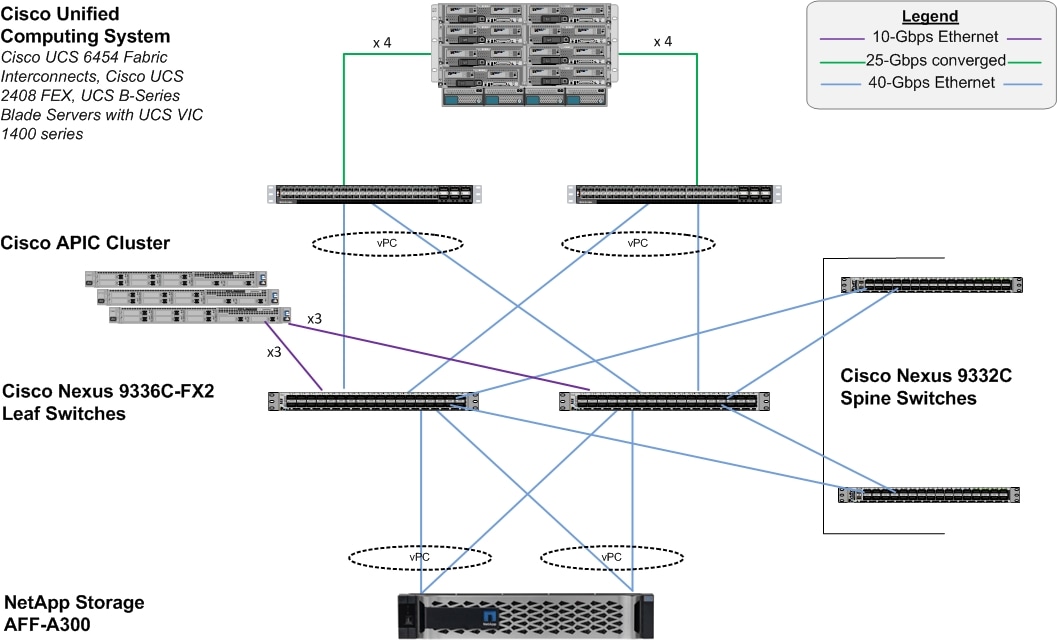
The reference architecture includes the following hardware configuration:
· Three Cisco APICs
· Two Cisco Nexus 9332C fixed spine witches
· Two Cisco Nexus 9336C-FX2 leaf switches
· Two Cisco UCS 6454 fabric interconnects
· One chassis of Cisco UCS blade servers {Cisco UCS B480 M5]
· One NetApp AFF A300 (HA pair) running ONTAP 9.6 with disk shelves populated with solid state drives (SSD)
![]() All systems and fabric links feature redundancy and provide end-to-end high availability. Although this is the base design, each of the components can be scaled flexibly to support specific business requirements. For example, more (or different) blades and chassis could be deployed to increase compute capacity, additional disk shelves could be deployed to improve I/O capacity and throughput, or special hardware or software features could be added to introduce new features.
All systems and fabric links feature redundancy and provide end-to-end high availability. Although this is the base design, each of the components can be scaled flexibly to support specific business requirements. For example, more (or different) blades and chassis could be deployed to increase compute capacity, additional disk shelves could be deployed to improve I/O capacity and throughput, or special hardware or software features could be added to introduce new features.
![]() While it is possible to use 100GbE links between Cisco UCS 6454 FIs and Cisco Nexus 9336C-FX2 leaf switches with compatible cables, 40GbE was tested with the design.
While it is possible to use 100GbE links between Cisco UCS 6454 FIs and Cisco Nexus 9336C-FX2 leaf switches with compatible cables, 40GbE was tested with the design.
![]() While both Cisco Nexus 9336C-FX2 and Nexus 9332C support 40/100-Gbps, 40GbE compliant cables were used for the connectivity; 40GbE was tested with the design.
While both Cisco Nexus 9336C-FX2 and Nexus 9332C support 40/100-Gbps, 40GbE compliant cables were used for the connectivity; 40GbE was tested with the design.
![]() Each Cisco UCS blade server must use a combination of Cisco VIC 1440 and Cisco VIC 1480 as with Cisco UCS 2408 FEX, VIC 1440 does not support port expander.
Each Cisco UCS blade server must use a combination of Cisco VIC 1440 and Cisco VIC 1480 as with Cisco UCS 2408 FEX, VIC 1440 does not support port expander.
Software Revisions
Table 1 lists the software revisions for this solution.
| Layer |
Device |
Image |
Comments |
| Compute |
Cisco UCS 6454 Fabric Interconnects, UCS B480 M5 |
4.0(4g) |
Includes the Cisco UCS-IOM 2408, Cisco UCS Manager, Cisco UCS VIC 1440/1480 |
| Network |
Cisco APICs Cisco Nexus 9000 ACI |
4.2(3l) aci-n900- 14.2(3l) |
|
| Storage |
NetApp AFF A300 |
ONTAP 9.6 |
NetApp SnapCenter 4.3 |
| Operating System |
|
RHEL 8.0 SLES for SAP 15 Sp1 |
With compatible enic and fnic drivers versions |
Configuration Guidelines
This document explains how to configure a fully redundant, highly available configuration for a FlexPod unit with ONTAP storage. Therefore, a reference is made to which component is being configured with each step, either 01 or 02 or A and B. For example, node01 and node02 are used to identify the two NetApp storage controllers that are provisioned with this document, and Cisco Nexus A or Cisco Nexus B identifies the pair of Cisco Nexus switches that are configured. The Cisco UCS fabric interconnects are similarly configured. Additionally, this document details the steps for provisioning multiple Cisco UCS hosts, and these examples are identified as: single-host01 or multi-host01 to represent infrastructure hosts deployed based on a use-case to each of the fabric interconnects in this document. Finally, to indicate that you should include information pertinent to your environment in a given step, <text> appears as part of the command structure. See the following example for the network port vlan create command:
Usage:
network port vlan create ?
[-node] <nodename> Node
{ [-vlan-name] {<netport>|<ifgrp>} VLAN Name
| -port {<netport>|<ifgrp>} Associated Network Port
[-vlan-id] <integer> } Network Switch VLAN Identifier
Example:
network port vlan create -node <node01> -vlan-name a0a-<vlan id>
This document is intended to enable you to fully configure the customer environment. In this process, various steps require you to insert customer-specific naming conventions, IP addresses, and VLAN schemes, as well as to record appropriate MAC addresses. Table 2 lists the VLANs necessary for deployment as outlined in this guide.
| VLAN Name |
VLAN Purpose |
ID Used in validation setup |
| Out of Band Mgmt |
VLAN for out-of-band management interfaces |
76 |
| iSCSI-A |
VLAN for iSCSI Boot on Fabric A |
128 |
| iSCSI-B |
VLAN for iSCSI Boot on Fabric B |
129 |
Physical Infrastructure
FlexPod Cabling
The information in this section is provided as a reference for cabling the physical equipment in a FlexPod environment. To simplify cabling requirements, , the diagrams include both local and remote device and port locations.
The cabling diagram in this section contains details for the prescribed and supported configuration of the NetApp AFF A300 running NetApp ONTAP® 9.6.
![]() For any modifications of this prescribed architecture, consult the NetApp Interoperability Matrix Tool (IMT).
For any modifications of this prescribed architecture, consult the NetApp Interoperability Matrix Tool (IMT).
This document assumes that out-of-band management ports are plugged into an existing management infrastructure at the deployment site. These interfaces will be used in various configuration steps. Make sure to use the cabling directions in this section as a guide.
The NetApp storage controller and disk shelves should be connected according to best practices for the specific storage controller and disk shelves. For disk shelf cabling, refer to NetApp Support.
Figure 2 illustrates the cable connections used in the validation lab for the FlexPod topology based on the Cisco UCS 6454 Fabric Interconnects. Also, 40GbE links connect the Cisco UCS Fabric Interconnects to the Cisco Nexus Switches and 40GbE links connect the NetApp AFF controllers to the Cisco Nexus Switches. Additional 1Gb management connections will be needed for an out-of-band network switch that sits apart from the FlexPod infrastructure. Each Cisco UCS fabric interconnect and Cisco Nexus switch is connected to the out-of-band network switch, and each AFF controller has two connections to the out-of-band network switch.
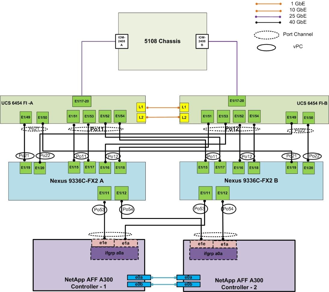
Figure 3 Spines, Leaves, and APICs Cabling
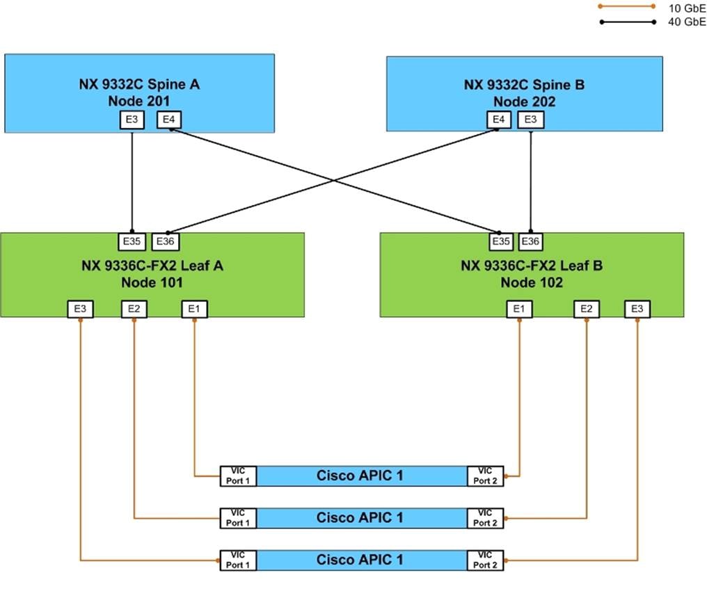
![]() With Cisco Nexus 9336C-FX2 in ACI mode, ports 31-36 support uplink and requires 2 ports for spine pair, make sure you are using ports 35-36. Refer to https://www.cisco.com/c/en/us/td/docs/switches/datacenter/nexus9000/hw/aci_9336cfx2_hig/guide/b_n9336cFX2_aci_hardware_installation_guide/b_n9336cFX2_aci_hardware_installation_guide_chapter_01.html for more information. Cisco Nexus 9336C-FX2 in ACI mode supports 10Gb with a QSA adapter (CVR-QSF-SFP10G).
With Cisco Nexus 9336C-FX2 in ACI mode, ports 31-36 support uplink and requires 2 ports for spine pair, make sure you are using ports 35-36. Refer to https://www.cisco.com/c/en/us/td/docs/switches/datacenter/nexus9000/hw/aci_9336cfx2_hig/guide/b_n9336cFX2_aci_hardware_installation_guide/b_n9336cFX2_aci_hardware_installation_guide_chapter_01.html for more information. Cisco Nexus 9336C-FX2 in ACI mode supports 10Gb with a QSA adapter (CVR-QSF-SFP10G).
Figure 4 Sample of Leaf Switches to Management PoD Nexus Switches Connectivity
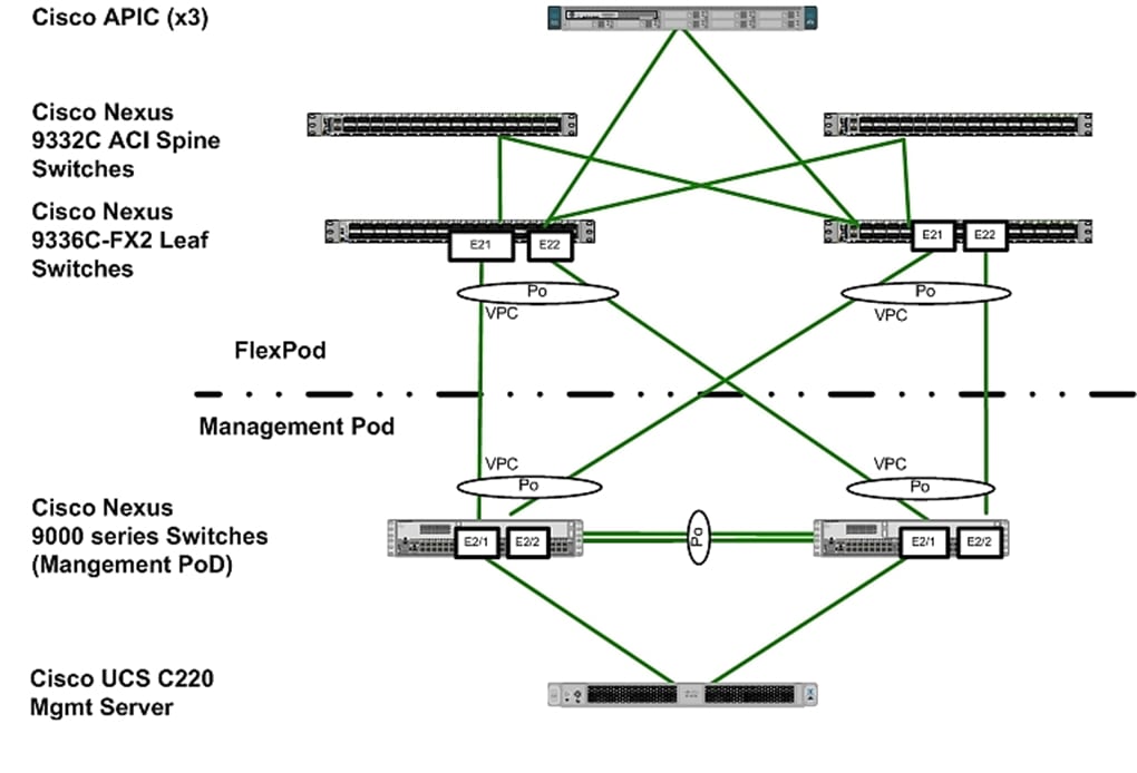
![]() Validation setup uses a separate Management PoD (optional in customer installations) which connects to ACI leaves in a back-to-back vPC configuration.
Validation setup uses a separate Management PoD (optional in customer installations) which connects to ACI leaves in a back-to-back vPC configuration.
The following sections provide a detailed procedure to configure the Cisco Application Centric Infrastructure (ACI) fabric for SAP HANA environment. The network configuration in this section is based on the cabling details described in the FlexPod Cabling section. Follow the guidelines provided in this section to configure the switches for FlexPod Cisco ACI for SAP HANA solution.
Cisco Application Policy Infrastructure Controller (APIC) Configuration
This section provides the required configuration details for setting up Cisco APICs.
In ACI, both spine and leaf switches are configured using APIC, individual configuration of the switches is not required. Cisco APIC discovers the ACI infrastructure switches using LLDP and acts as the central control and management point for the entire configuration. The configuration begins with setting the CIMC IPs of the APIC nodes.
Cisco IMC Configuration
To configure the IP address on the Cisco IMC, follow these steps:
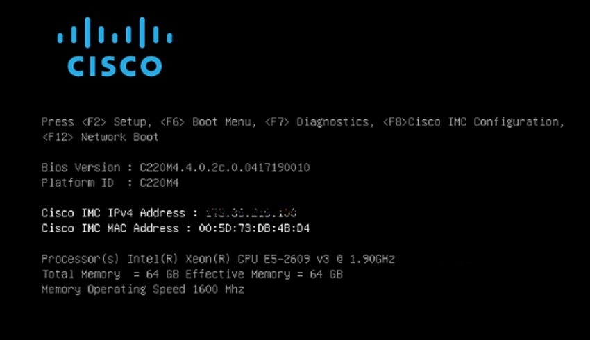
1. With a direct attached monitor and keyboard press F8 when the following screen appears.
Figure 5 Cisco IMC Configuration
2. Configure the Cisco IMC as required to be accessible from the management LAN.
Figure 6 Cisco IMC Configuration Utility
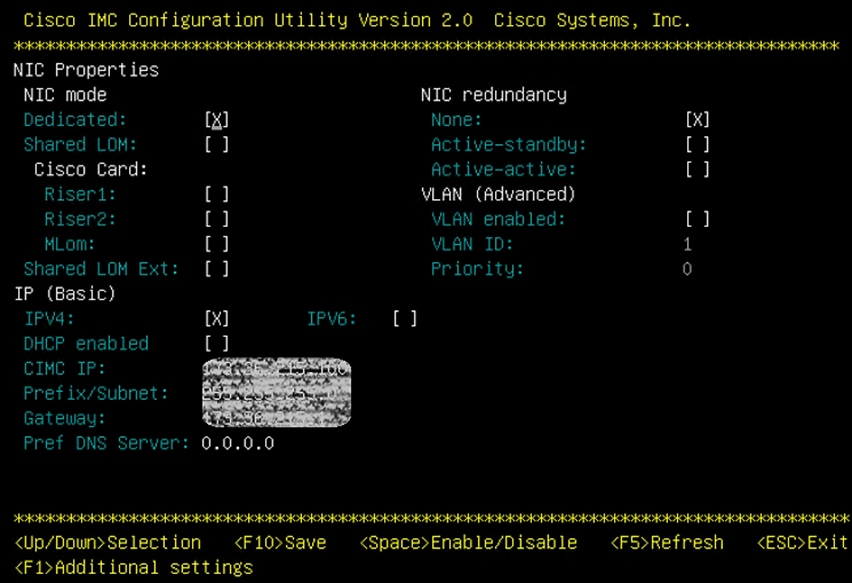
3. When connecting the Cisco IMC to Management Switch, complete the following:
a. Choose Dedicated under NIC model.
b. Enter the IP address for CIMC which is accessible from the Management Network.
c. Enter the Subnet mask for CIMC network.
d. Enter the Default Gateway for CIMC network. Choose NIC redundancy as None.
e. Enter the Default password for admin user under Default User (Basic) and Reenter password.
f. Press F10 to save your configuration.
g. Press F5 to refresh your settings after 45 seconds to see the changes.
h. Press ESC to exit and continue booting with the new settings.
Configure Cisco IMC NTP
To configure Cisco IMC NTP, follow these steps:
1. Browse to https://<cimc_ip_address>.
2. Log in using admin as username and use the password defined during CIMC setup.
3. Click the Admin tab.
4. Click Networking.
5. Click NTP Settings.
6. Check Enable NTP.
7. Enter the IP address of one or more NTP servers.
8. Click Save Changes.
Cisco APIC Initial Configuration Setup
To configure Cisco APIC, follow these steps:
1. Log into the APIC CIMC using a web browser and launch the KVM.
2. Browse to https://<cimc_ip_address>.
3. Log in using admin as username and use the password defined during Cisco IMC setup.
4. From the Server tab, select Summary and click Launch KVM Console.
5. KVM application will be launched and initial APIC setup screen should be visible.
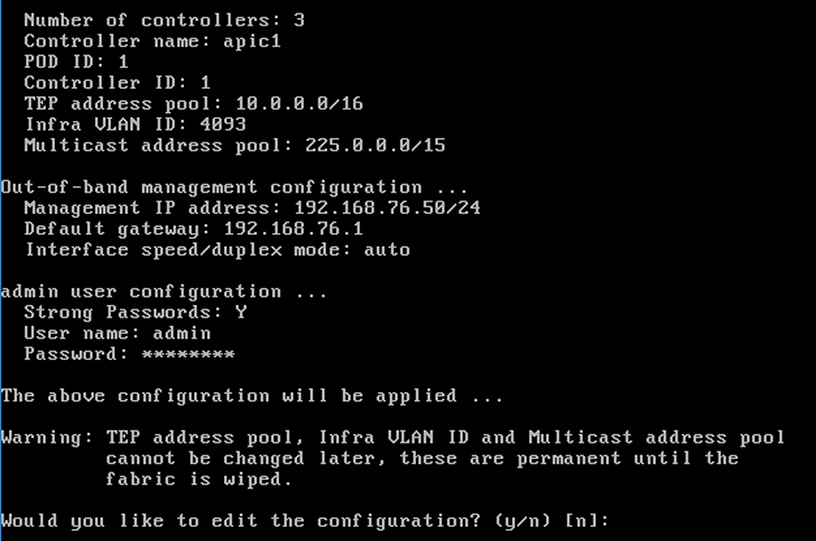
Figure 7 APIC Configuration
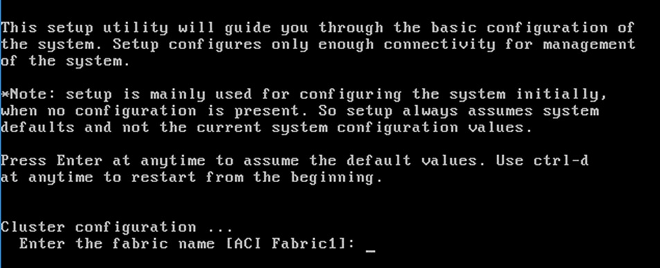
6. Press return to select the default value for Enter the fabric name. This value can be changed if desired.
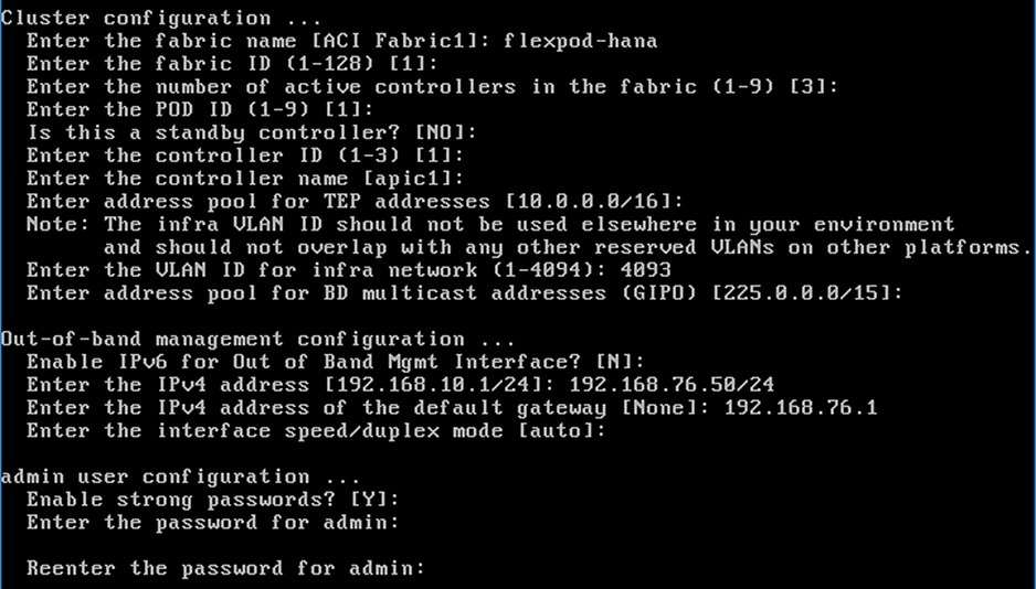
7. Press return to select the default value of three for Enter the number of controllers in the fabric. While the fabric can operate with a single APIC, 3 APICs are recommended for redundancy. While a minimum of 3 nodes are a minimum for production use-cases, up to 5 nodes may be needed in large installations.
8. Press return to select the default value for the POD ID as 1.
9. Press return to select the default value NO for the standby controller question.
10. Enter the controller number currently being set up under Enter the controller ID (1-3). Enter the value 1 and press enter.
11. Press return to retain the default value for controller name apic1. This can be changed if desired.
12. Press return to select the default pool under Enter the address pool for TEP addresses. If the network is already in use, please choose a different range.
13. Enter a unique unreserved VLAN for Enter the VLAN id for infra network.
14. Press return to select the default range for Enter address pool for BD multicast addresses.
15. Enter appropriate values for the out of band management network configuration. The out of band management IP address will be used to access the APIC from client browsers.
16. Press Y to enforce a strong password.
17. Enter the admin password (controller 1 only).
18. Press return to accept the configuration without changes.
19. Let the APIC complete its boot process.
Figure 8 APIC Initial Setup
![]() When APIC-1 boots up for the first time, it might take up to 5 minutes to allow login using the admin password set during the setup procedure. If something went wrong during the setup, APIC does allow login using a special user called rescue-user. If admin password was never set or was not setup properly, rescue-user will allow access to APIC without any password. If an admin password was set previously, use rescue-user with the admin password.
When APIC-1 boots up for the first time, it might take up to 5 minutes to allow login using the admin password set during the setup procedure. If something went wrong during the setup, APIC does allow login using a special user called rescue-user. If admin password was never set or was not setup properly, rescue-user will allow access to APIC without any password. If an admin password was set previously, use rescue-user with the admin password.
20. Repeat steps 1 through 18 for APIC controllers APIC 2 and APIC 3. Make sure to select the controller IDs and controller name accordingly for them.
![]() Only APIC 1 is configured with a password. APIC 2 and 3 will get the password from APIC 1 once the Cisco ACI fabric is configured.
Only APIC 1 is configured with a password. APIC 2 and 3 will get the password from APIC 1 once the Cisco ACI fabric is configured.
Cisco ACI Fabric Discovery
The APIC is responsible for fabric discovery. It manages the device addressing. The fabric discovery happens via Link Layer Discovery Protocol (LLDP).
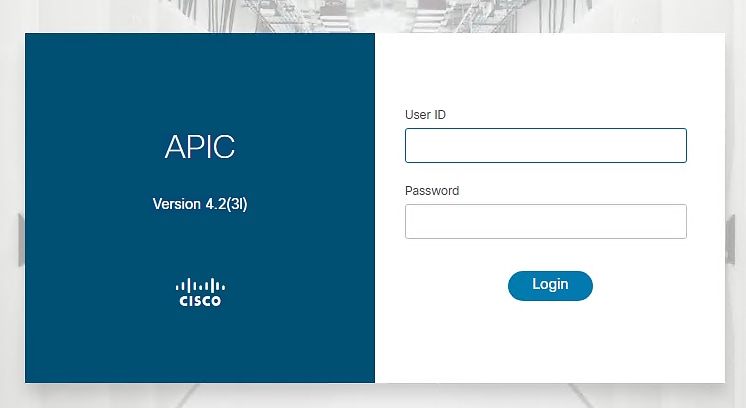
1. Log into the Cisco APIC GUI using a web browser:
2. Browse to https://<Out of Band IP address of APIC 1>.
3. Log in using admin as username and use the password defined during initial setup.
Figure 9 APIC Login Screen
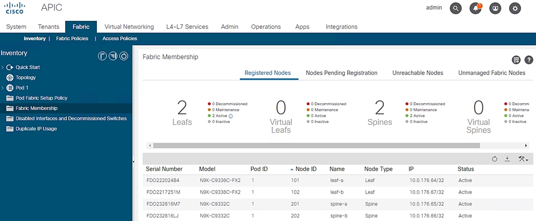
4. Click Fabric from the top bar. Under INVENTORY, expand Fabric Membership.
5. At least one of the leaves should be visible. The Leaf node connected to active port of bonded interface of the APIC controller-1 is the first to be discovered via LLDP.
6. Log into the leaf using console connection (admin/<no password needed>) and use the serial number to identify discovered leaf (Leaf-1 or Leaf-2 in the physical setup).
Switch# show inventory
NAME: "Chassis", DESCR: "Nexus C9336C-FX chassis"
PID: N9K-C9336C-FX2 , VID: V01 , SN: FDO222024B4
Switch# show inventory
NAME: "Chassis", DESCR: "Nexus C9336C-FX chassis"
PID: N9K-C9336C-FX2 , VID: V01 , SN: FDO2217251M
7. Double-click the identified leaf description on the right-hand side and assign 101 as NODE ID value and NODE NAME <device name>. Click UPDATE.
8. As the fabric discovery continues, the leaf discovers the spine switches it is connected to and they are populated under the Fabric Membership window. Repeat Step 6 to assign the NODE ID and NODE NAME to these spine switches.
9. When the spine switches are configured, they discover the remaining leaf switches they are connected to the information is populated under the Fabric Membership window. Repeat Step 6 to assign the NODE ID and NODE NAME to these leaf switches [in our case the remaining leaf switch].
10. When the NODE ID and NODE NAME values are assigned, APIC assigns IP addresses from TEP, the pool defined during initial setup.
11. Fabric now self assembles and the discover process is complete.
Figure 10 Fabric Membership
Configure NTP for Cisco ACI Fabric
Fabric policies configure interfaces that connect spine and leaf switches. Fabric policies can enable features such as monitoring (statistics collection and statistics export), troubleshooting (on-demand diagnostics and SPAN), or NTP. Fabric policies govern the operation of internal fabric interfaces.
To configure NTP server for Cisco ACI fabric, follow these steps:
1. Click Fabric and select Fabric POLICIES .
2. Expand Policies in the left pane and then expand PoD.
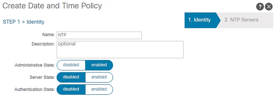
3. Right-click Date and Time and select Create Date and Time Policy.
4. In the menu box, enter NTP as the policy name; select the Administrative State as enabled and the Authentication State as disabled.
5. Click NEXT.
Figure 11 ACI Fabric NTP Configuration
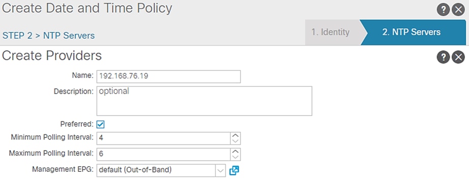
6. On the NTP Servers window, Click + to add NTP servers.
7. Enter the IP address of the NTP server in the name field and choose the option default (Out-of-Band) for Management EPG.
8. Click OK.
Figure 12 NTP Server Configuration
9. Click FINISH.POD Policy Group
To create a POD Policy, follow these steps:
1. Click Fabric and select Fabric POLICIES.
2. Expand POD Policies in the left pane.
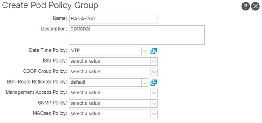
3. Right-click the Policy Groups and then select Create POD Policy Group.
4. Enter HANA-PoD as the policy name.
5. Select the option NTP from the Date Time Policy drop-down list.
6. Select default for BGP Route Reflector Policy from the drop-down list.
7. Click Submit.
Figure 13 Create POD Policy
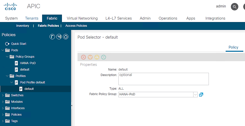
To set default POD for the configuration, follow these steps:
1. Click Fabric and select Fabric POLICIES .
2. Expand the POD Policies and then expand Profiles.
3. Click Pod Profile default.
4. Select HANA-PoD for the Fabric Policy Group from the drop-down list.
5. Click Submit.
Figure 14 POD Profile – default
Configuring Access Policies
Access policies configure external-facing interfaces that connect to devices such as hosts, network attached storage or layer 2 switches for example, Cisco UCS Fabric Interconnects. Access policies enable configurating port channels and virtual port channels, protocols such as Link Layer Discovery Protocol (LLDP), Cisco Discovery Protocol (CDP), or Link Aggregation Control Protocol (LACP).
As observed in the reference architecture, all the devices namely Cisco UCS Fabric Interconnects, NetApp controllers and management PoD Nexus switches connect to leaf switches using vPC. The leaf switches do not have any direct connected end devices [either in access mode or in Port Channel configuration]. So, you will see we create vPC based policies for this landscape.
In this section, initially Interface Policies that configure various protocol options such as Link Level, CDP, LLDP and Port Channel are defined. The interface profiles (specifying the switch interfaces intended for configuration) along with Interface Policies (interface level policies) together map to Interface Policy Groups (IPGs – intended for association of set of interface level policies) to define the vPC configurations that leaf switches use to connect to end devices.
Further VLAN pools – policies defining ID ranges used for VLAN encapsulation, along with connectivity options such as Physical Domain – single management domain that is the scope for policy enforcement, and Attachable Access Entity Profile [AAEP] – a template to deploy policies on a designated set of leaf ports are defined.
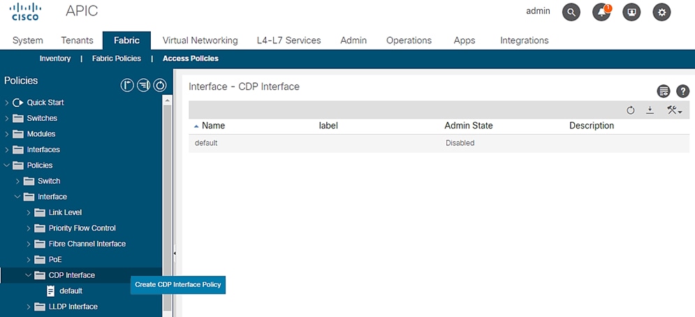
CDP Interface Policies
To configure the interface policies, follow these steps:
1. Click Fabric and select Access Policies.
2. From the left menu bar, expand Policies.
3. Expand Interface and select CDP interface. A ‘default’ policy with CDP disabled already exists.
4. Right-click the CDP Interface and select Create CDP Interface Policy.
Figure 15 Access Policies - CDP Policy Creation
5. In the menu box, enter CDP_enabled as the policy name and select Admin State as Enabled.
Figure 16 Access Policies – CDP_enabled
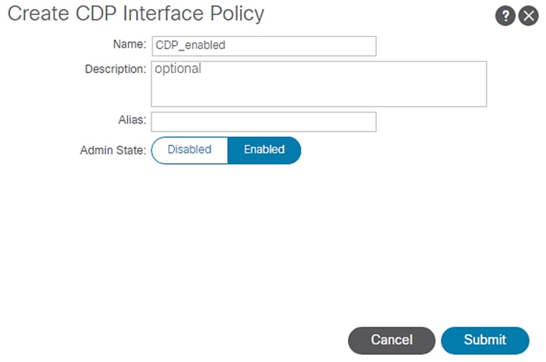
6. Click Submit.
7. Right-click and select Create CDP Interface Policy again.
8. In the menu box, enter CDP_disabled as the policy name and select Admin State as Disabled.
Figure 17 Access Policies – CDP disabled
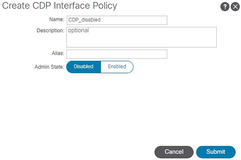
9. Click Submit.
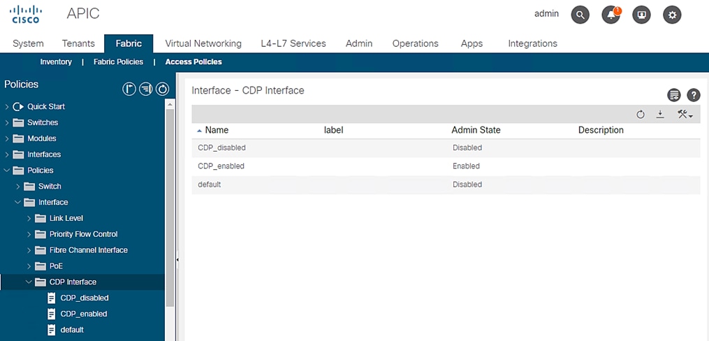
To summarized, you created two policies; one with CDP enabled and another disabling it.
Figure 18 Access Policies – CDP Interface policies
LLDP Interface Policies
To configure th LLDP Interface Policies, follow these steps:
1. Click Fabric and select Access Policies.
2. From the left menu bar, expand Policies.
3. Expand Interface and select LLDP Interface. A ‘default’ policy with LLDP enabled for both Receive and Transmit states already exists.
Figure 19 Access Policies - LLDP Policy Creation
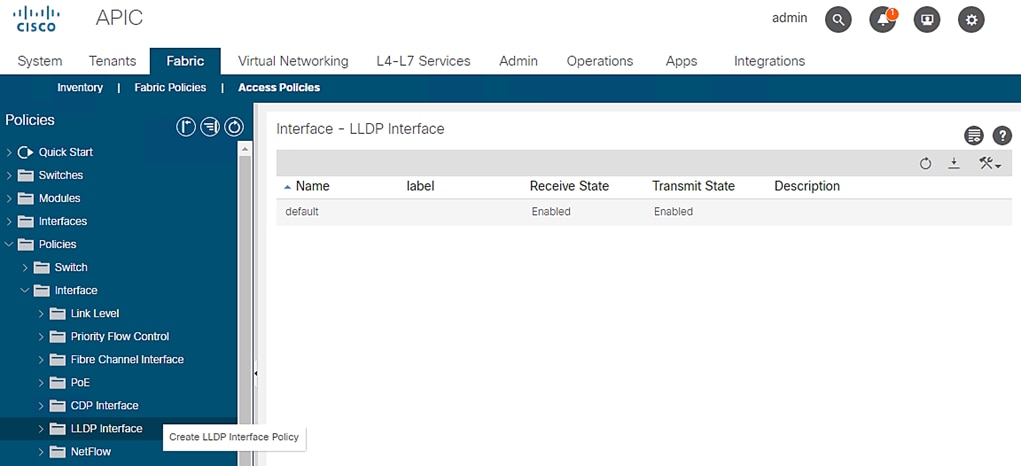
4. Right-click LLDP Interface and select Create LLDP Interface Policy.
5. In the menu box, enter LLDP_Enabled as the policy name and set both Transmit State and Receive State Enabled.
Figure 20 Access Policies - LLDP Enabled
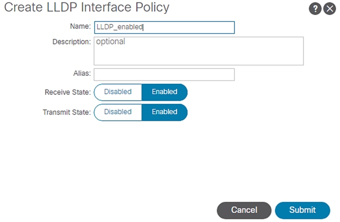
6. Click Submit.
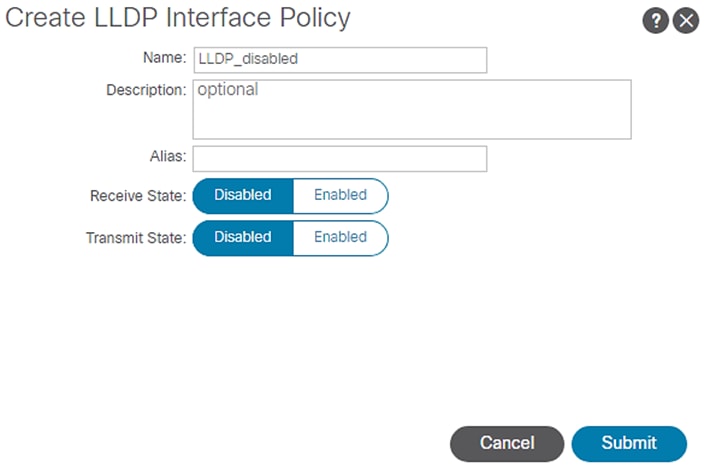
7. Similarly create LLDP_Disabled with both Transmit and Receive state set to disabled as shown below.
Figure 21 Access Policies - LLDP Disabled
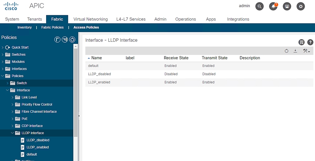
To summarize, you created two LLDP policies; one with states enabled and another set to disabled.
Figure 22 Access Policies – LLDP Interface Policies
LACP Interface Policies
To configure the LACP Interface Policies, follow these steps:
1. Click Fabric and select Access Policies.
2. From the left menu bar, expand Policies.
3. Expand Interfaces and select Port Channel. A ‘default’ policy with Mode set to ‘Static Channel – Mode On’ already exists.
Figure 23 Access Policies - LACP Policy Creation
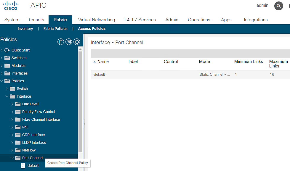
4. Right-click Port Channel Policies and select Create LACP Policy.
5. In the menu box, enter LACP_Active as the policy name and select LACP Active for Mode. Leave the remaining options as default.
Figure 24 Access Policies – LACP Active
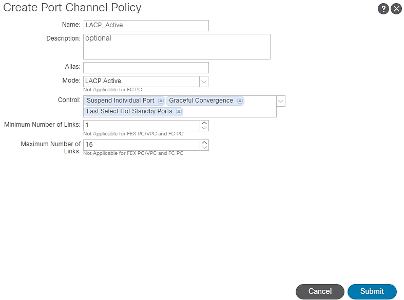
6. Click Submit.
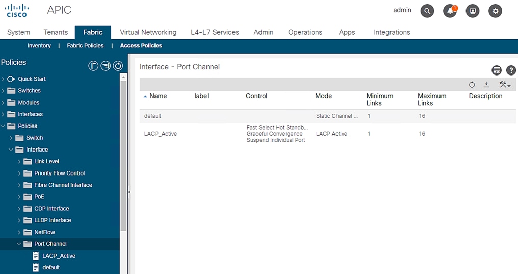
You now have a LACP_Active policy.
Figure 25 Access Policies – Interface Port Channel Policy
Link Level Policy
To create link level policies for the interfaces, follow these steps:
1. Click Fabric and select Access Policies .
2. From the left menu bar, expand Policies.
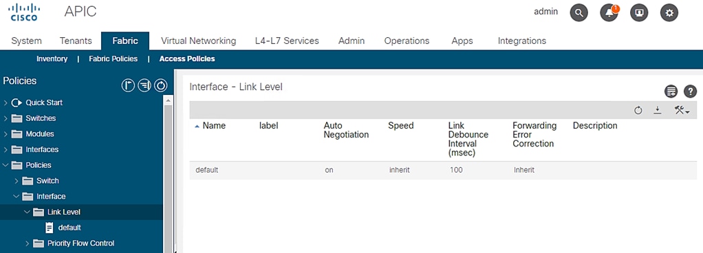
3. Expand Interfaces and select Link Level. A ‘default’ policy with speed set to ‘inherit’ already exists.
Figure 26 Access Policies – Link Level Policy Creation
4. Right-click Link Level and select Create Link Level Policy.
5. Enter 40G as the name of Link Level Policy.
6. Select the speed to be 40 Gbps. Leave remaining options as default.
Figure 27 Access Policies – 40G Link Level Policy
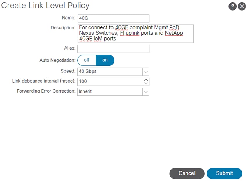
7. Click Submit.
![]() Depending on the supported bandwidth of end devices that connect to leaf switches and specific use-case, you may need to create additional Link Level policies with 10G or 25G link speed. We could have created a 100GE Link level policy for use with FI uplink ports connectivity provided we have 100G E compatible cables.
Depending on the supported bandwidth of end devices that connect to leaf switches and specific use-case, you may need to create additional Link Level policies with 10G or 25G link speed. We could have created a 100GE Link level policy for use with FI uplink ports connectivity provided we have 100G E compatible cables.
VLAN Pool for SAP HANA
To create VLANs in ACI Fabric for SAP HANA, follow these steps:
1. Click Fabric and select Access Policies .
2. From the left menu bar, expand Pools.
3. Right-click VLAN and select Create VLAN Pool.
4. Enter HANA-VLANs as the Pool name and select Static Allocation.
5. Under Encap Blocks click + to add a VLAN range.
6. Enter the VLAN range to be used for SAP HANA.
Figure 28 VLAN Pool Block Range
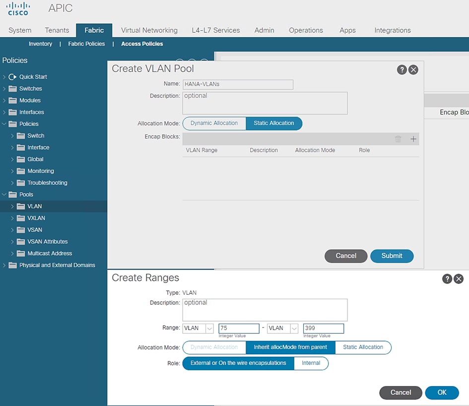
7. Click OK.
Figure 29 VLAN Pool Identity
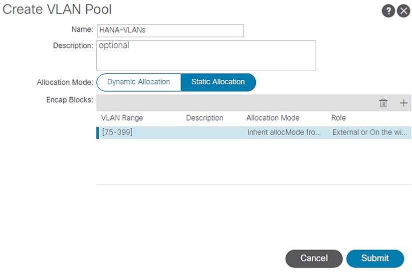
8. Click Submit.
Domain Configuration
The physical domain profile stores the physical resources (ports and port-channels) and encap resources (VLAN/VXLAN) that should be used for endpoint groups associated with this domain.
To create Physical Domain in the Cisco ACI Fabric for SAP HANA, follow these steps:
1. Click Fabric and select Access Policies.
2. From the left pane, expand Physical and External Domains.
3. Right-click the Physical Domains and select Create Physical Domain.
4. Enter HANA for the physical domain name field.
5. Select HANA-VLANs for the VLAN Pool field from the drop-down list.
Figure 30 Physical Domain VLAN Properties
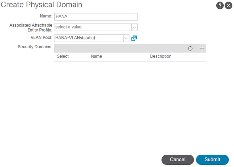
6. Click Submit
![]() Associated Attachable Entity Profile will be added later and bound to the Physical Domain.
Associated Attachable Entity Profile will be added later and bound to the Physical Domain.
Attachable Access Entity Profile Configuration
The Attachable Access Entity Profile (AAEP) is used to map domains (physical or virtual) to interface policies, with the end goal of mapping VLANs to interfaces.
To configure the Attachable Access Entity Profile, follow these steps:
1. Click Fabric and select Access Policies.
2. Expand Policies on the left pane. Expand Global.
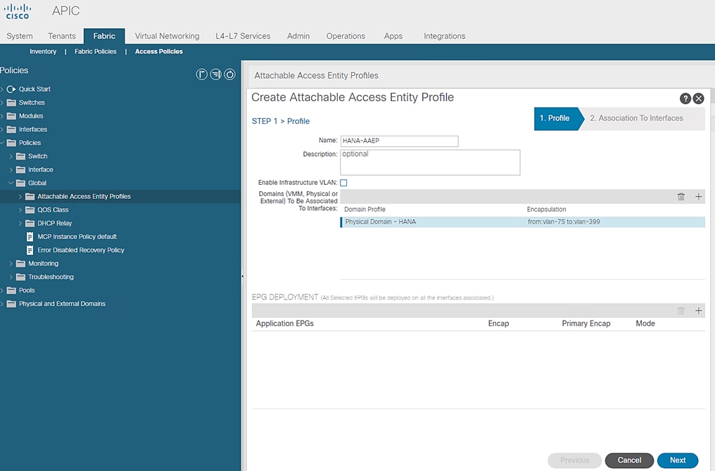
3. Right-click the Attachable Access Entity Profile and select Create Attachable Access Entity Profile.
4. Enter HANA-AAEP as the profile name.
5. Under Domains, click the + symbol to add Domain Profile.
6. From the Domain Profile drop-down list select HANA (Physical) and click Update.
Figure 31 Attachable Access Entity Profile Domains
7. Click Next.
Figure 32 Attachable Access Entity Profile Interface
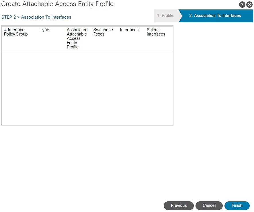
8. Click FINISH.
![]() EPG information addition of step 1 and Interfaces association of step 2 to the AAEP will be done later.
EPG information addition of step 1 and Interfaces association of step 2 to the AAEP will be done later.
Leaf Interface Policy Groups and Interface Profiles
This section describes the configuration of Interface Policy Groups [IPG] required for the vPC connections from Cisco ACI Leaf switches to Cisco UCS Fabric Interconnects, NetApp controllers and Management PoD Nexus switches.
VPC Configuration for Cisco UCS
This section describes the configuration of policies required for VPC connection from ACI Leaf switches to the Cisco UCS FIs.
Policy Group Configuration for VPC Connectivity Cisco UCS
To create VPC interface policies for the interfaces connecting to Cisco UCS Fabric Interconnect A, follow these steps:
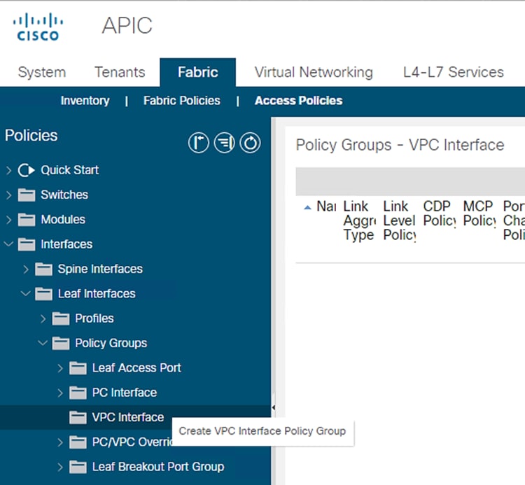
1. Click Fabric and select Access Policies.
2. Expand the Interfaces Policies in the left pane. Expand Leaf Interfaces.
3. Expand Policy Groups and right-click the VPC Interface and select Create VPC Interface Policy Group.
Figure 33 Access Policies – VPC interface Policy Groups Creation
4. Enter vPC-FiA-11 for the Name of Policy group.
5. Select 40G for Link level Policy from the drop-down list.
6. Select CDP_Enabled for CDP Policy from the drop-down list.
7. Select LLDP_Disabled for LLDP Policy from the drop-down list.
8. Select LACP_Active for Port Channel Policy from the drop-down list.
9. Select HANA-AAEP for Attached Entity Profile from the drop-down list.
Figure 34 VPC Interface Policy Group for Fabric Interconnect A

10. Click Submit.
To create VPC interface policies for the interfaces connecting to UCS Fabric Interconnect B, follow these steps:
1. Click Fabric and select Access Policies .
2. Expand the Interfaces Policies in the left pane. Expand Leaf Interfaces.
3. Expand Policy Groups and right-click the VPC Interface and select Create VPC Interface Policy Group.
4. Enter vPC-FiB-12 for the Name of Policy group.
5. Select 40G for Link level Policy from the drop-down list.
6. Select CDP_Enabled for CDP Policy from the drop-down list.
7. Select LLDP_Disabled for LLDP Policy from the drop-down list.
8. Select LACP_Active for LACP Policy from the drop-down list.
9. Select HANA-AAEP for Attached Entity Profile from the drop-down list.
10. Click Submit.
Figure 35 vPC Interface Policy Group for Fabric Interconnect B

To create separate IPG for vPC connecting to UCS Fabric Interconnects for exclusive SAP HANA backup network usage, follow these steps:
Cisco UCS Fabric Interconnect A
1. Click Fabric and select Access Policies.
2. Expand the Interfaces Policies in the left pane. Expand Leaf Interfaces.
3. Expand Policy Groups and right-click the VPC Interface and select Create VPC Interface Policy Group.
4. Enter vPC-FiA-21 for the Policy group name.
5. Select 40GB for Link level Policy from the drop-down list.
6. Select CDP_Enabled for CDP Policy from the drop-down list.
7. Select LLDP_Disabled for LLDP Policy from the drop-down list.
8. Select LACP_Active for LACP Policy from the drop-down list.
9. Select HANA-Physical for Attached Entity Profile from the drop-down list.
Figure 36 IPG config for vPC - Exclusive Backup Network Usage FI-A
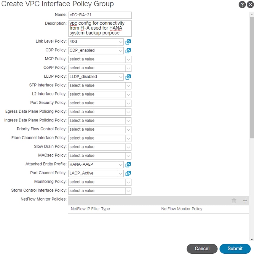
10. Click Submit.
Cisco UCS Fabric Interconnect B
1. Click Fabric and select Access Policies .
2. Expand the Interfaces Policies in the left pane. Expand Leaf Interfaces.
3. Expand Policy Groups and right-click the VPC Interface and select Create VPC Interface Policy Group.
4. Enter vPC-FiB-22 for the Policy group name.
5. Select 100GB for Link level Policy from the drop-down list.
6. Select CDP_Enabled for CDP Policy from the drop-down list.
7. Select LLDP_Disabled for LLDP Policy from the drop-down list.
8. Select LACP_Active for LACP Policy from the drop-down list.
9. Select HANA-AAEP for Attached Entity Profile from the drop-down list.
Figure 37 IPG config for vPC - Exclusive Backup Network Usage FI-B
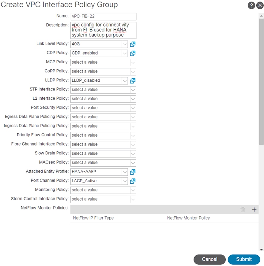
10. Click Submit.
Interface Profile Configuration related to FI connections
This section describes the procedure to create the interface profiles that specify which interfaces are intended for configuration and that which inherit the associated policy groups.
To create the interface profiles referencing ports connecting to Cisco UCS Fabric Interconnect A, follow these steps:
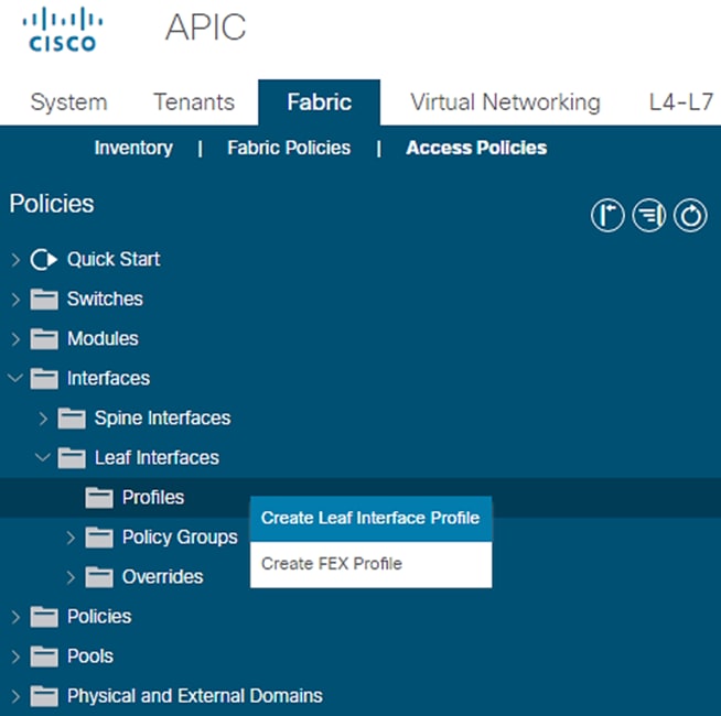
1. Click Fabric and select Access Policies.
2. Expand the Interfaces Policies in the left pane.
3. Expand Leaf Interfaces and right-click Profiles and select Create Leaf Interface Profile.
Figure 38 Leaf Interface Profile
4. Enter FiA-PO11 as the Interface Profile name.
Figure 39 Leaf Interface Profile Creation
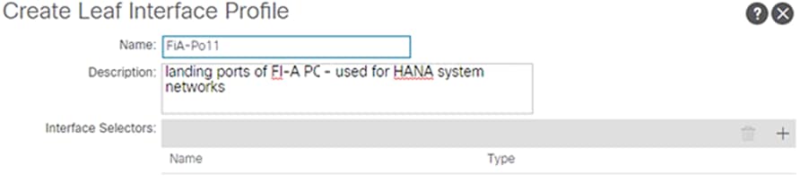
5. For Interface Selectors, click the + symbol to add interfaces.
6. Enter FiA-Po11-leaports for port selector identity name and 1/15,1/17 as the Interface IDs.
![]() These ports are connected to the Cisco UCS Fabric Interconnect A as described in the FlexPod Cabling section.
These ports are connected to the Cisco UCS Fabric Interconnect A as described in the FlexPod Cabling section.
7. Select vPC-FiA-11 for Interface Policy Group from the drop-down list.
Figure 40 Interface Port Selector Identity
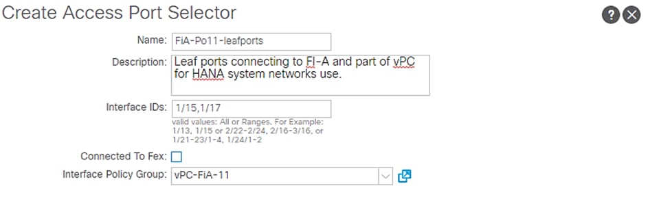
8. Click OK and then click Submit.
Similarly, create interface profiles for ports connecting to Cisco UCS Fabric Interconnect B:
1. Right-click Profiles and select Create Leaf Interface Profile.
2. Enter FiB-Po12 as the Interface Profile name for Interface Selectors, click the + symbol to add interfaces.
Figure 41 Leaf Interface Profile creation
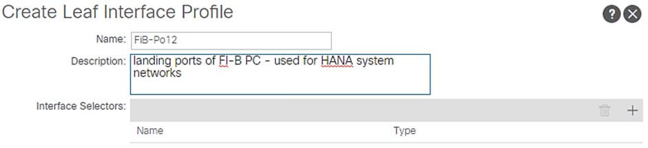
3. Enter FiB-Po12-leafports for port selector identity name and 1/16,1/18 for the Interface IDs.
4. For the Interface Policy Group select vPC-FiB-12 from the drop-down list.
Figure 42 Interface Port Selector Identity
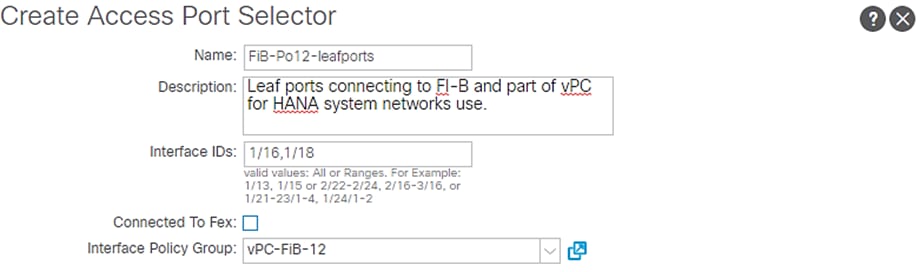
5. Click OK and then click Submit.
To configure the interfaces planned for the SAP HANA backup network connecting from either FIs, follow these steps:
1. Right-click Profiles and select Create Leaf Interface Profile.
2. Enter FiA-Po21 as the Interface Profile name.
Figure 43 Leaf Interface Profile Creation
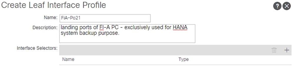
3. For Interface Selectors, click the + symbol to add interfaces.
4. Enter FI-A-PO21 for port selector identity name and 1/15 for the Interface ID.
5. Select vPC-FiA-21 for the Interface Policy Group from the drop-down list.
Figure 44 Interface Port Selector Identity
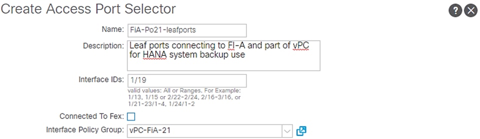
6. Click OK and then click Submit.
Cisco UCS FI-B
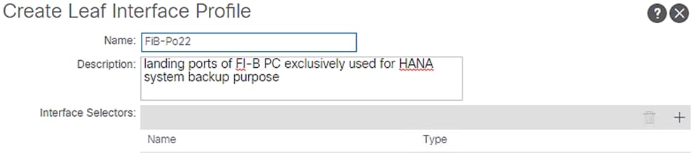
1. Right-click Profiles and select Create Leaf Interface Profile.
2. Enter FiB-Po22 as the Interface Profile name.
3. For Interface Selectors, click the + symbol to add interfaces.
Figure 45 Interface Profile Identity
4. Enter FI-B-PO22 for port selector identity name and 1/16 as the Interface ID.
5. Select vPC-FiB-22 for the Interface Policy Group from the drop-down list.
Figure 46 Interface Port Selector Identity
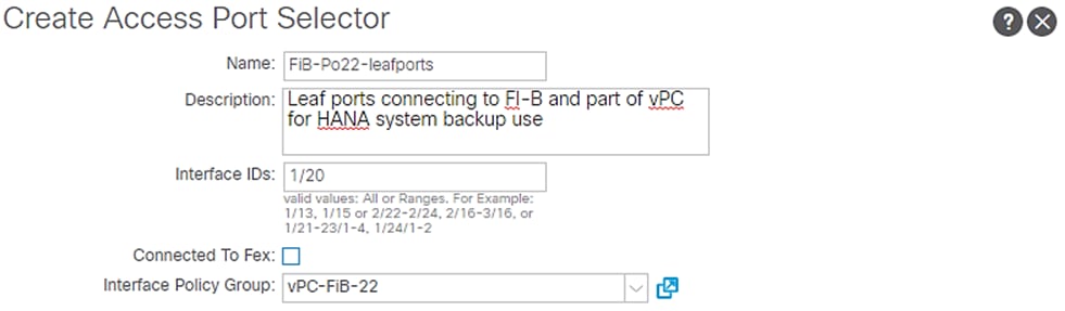
6. Click OK and then click Submit.
VPC Configuration for NetApp Storage
This section describes the configuration of policies required for VPC connection from ACI Leaf switches to the NetApp Storage Controllers.
Policy Group Configuration for VPC Connectivity to NetApp Storage
To create VPC interface policies for the interfaces connecting to the NetApp Storage Controller A, follow these steps:
1. Click Fabric and select Access Policies.
2. Expand the Interfaces Policies in the left pane. Expand Leaf Interfaces.
3. Expand Policy Groups and right-click the VPC Interface and select Create VPC Interface Policy Group.
4. Enter vPC-NetApp-CntrlA for the Policy Group name.
5. Select 40GB for Link level Policy from the drop-down list.
6. Select CDP_enabled for CDP Policy from the drop-down list.
7. Select LLDP_enabled for LLDP Policy from the drop-down list.
8. Select LACP_Active for LACP Policy from the drop-down list.
9. Select HANA-AAEP for Attached Entity Profile from the drop-down list.
Figure 47 Interface Policy Group for Netapp Controller-A

10. Click Submit.
To create VPC interface policy for the interfaces connecting to the NetApp Storage Controller B, follow these steps:
1. Right-click the VPC Interface and select Create VPC Interface Policy Group.
2. Enter vPC-NetApp-CntrlB for the Name of Policy group.
3. Select 40GB for Link level Policy from the drop-down list.
4. Select CDP_enabled for CDP Policy from the drop-down list.
5. Select LLDP_enabled for LLDP Policy from the drop-down list.
6. Select LACP_Active for LACP Policy from the drop-down list.
7. Select HANA-AAEP for Attached Entity Profile from the drop-down list.
Figure 48 Interface Policy Group for Netapp Controller-B

8. Click Submit.
Interface Profile Configuration related to NetApp Connections
To create VPC interface policies for the interfaces connecting to NetApp Storage, follow these steps:
1. Click Fabric and select Access Policies.
2. Expand the Interfaces Policies in the left pane.
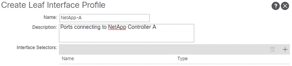
3. Expand Leaf Interfaces and right-click Profiles and select Create Leaf Interface Profile.
4. Enter Netapp-A as the Interface Profile name.
5. For Interface Selectors, click the + symbol to add interfaces.
Figure 49 Interface Profile Identity – NetApp Controller-A
6. Enter NetAppA-leafports for port selector identity name and 1/11 for the Interface ID.
7. Select vPC-NetApp-CntrlA for the Interface Policy Group from the drop-down list.
Figure 50 Interface Port Selector Identity – NetApp Controller-A
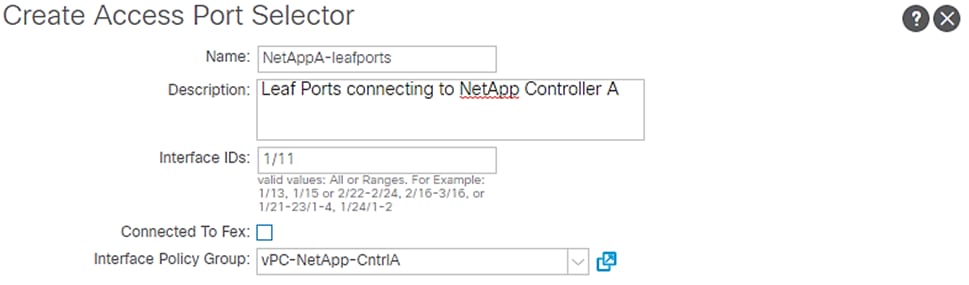
8. Click OK and then click Submit.
Controller-B
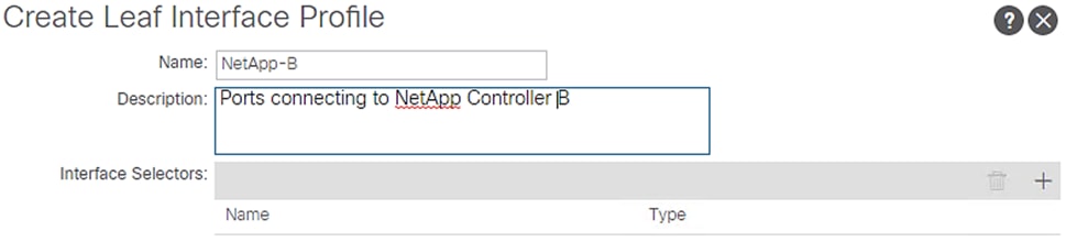
1. Right-click the Leaf Profiles and select Create Leaf Interface Profile.
2. Enter NetApp-B as the Interface Profile name.
3. For Interface Selectors, click the + symbol to add interfaces.
Figure 51 Interface Profile Identity – NetApp Controller-B
4. Enter NetAppB-leafports for the port selector identity name and 1/12 for the Interface ID.
5. Select vPC-NetApp-CntrlB for the Interface Policy Group from the drop-down list.
Figure 52 Interface Port Selector Identity – NetApp Controller-B
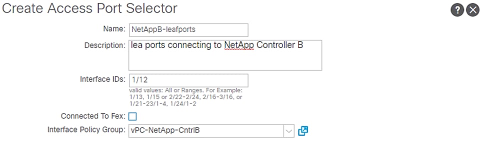
6. Click OK and then click Submit.
VPC Configuration for Management PoD
This section describes the configuration of policies required for VPC connection from Cisco ACI Leaf switches to Management PoD switches. In the validation setup, we have 40GbE capable Cisco Nexus 9000 series switches.
Policy Group Configuration for VPC Connectivity to Management PoD
To create VPC interface policies for the interfaces connecting to Nexus 9000 switches of the Management PoD, follow these steps:
1. Click Fabric and select Access Policies.
2. Expand the Interfaces Policies in the left pane. Expand Leaf Interfaces.
3. Expand Policy Groups and right-click the VPC Interface and select Create VPC Interface Policy Group.
4. Enter b2b-vPC-Mgmt-PoD for the Policy Group name.
5. Select 40G for Link level Policy from the drop-down list.
6. Select CDP_enabled for CDP Policy from the drop-down list.
7. Select LLDP_disabled for LLDP Policy from the drop-down list.
8. Select LACP_Active for LACP Policy from the drop-down list.
9. Select HANA-AAEP for Attached Entity Profile from the drop-down list.
Figure 53 Interface Policy Group for Management PoD Connection (if in use)

10. Click Submit.
Interface Profile Configuration Related to Management PoD Connections
This section describes the procedure to create the interface profiles that will inherit the associated policy groups.
To create the interface profiles for ports connecting to Cisco Nexus 9000 switches of the Management PoD, follow these steps:
1. Click Fabric and select Access Policies.
2. Expand the Interfaces Policies.
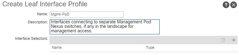
3. Expand Leaf Interfaces and right-click Profiles and select Create Leaf Interface Profile.
4. Enter Mgmt-PoD as the Name of the Interface Profile.
5. For Interface Selectors, click the + symbol to add interfaces.
Figure 54 Interface Profile Identity – Mgmt PoD
6. Enter Mgmt-PoD-leafports for port selector identity name and 1/21-22 for the Interface IDs.
7. Select b2b-vPC-Mgmt-PoD for the Interface Policy Group from the drop-down list.
Figure 55 Interface Port Selector Identity – Mgmt PoD
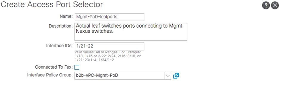
8. Click OK and then click Submit.
Switch Policy Configuration
This section describes the procedure to configure Switch Policy, which will be applied to the Cisco ACI Leaf switches.
To configure the Switch Policy, follow these steps:
1. Click Fabric and select Access Policies .
2. Expand Policies. Expand Switch.
3. Click Virtual Port Channel Default.
Figure 56 Switch Policy Configuration
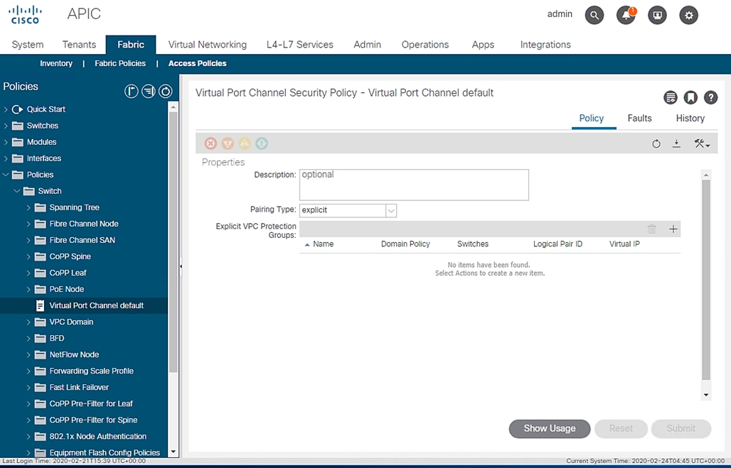
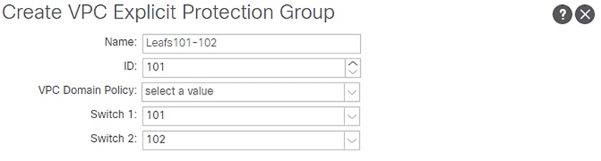
4. Under Explicit VPC Protection Groups, click the + symbol.
5. Enter Leafs101-102 as the VPC Explicit Group name.
6. Enter 100 in the ID field.
7. Ensure 101 is selected for Switch 1 and 102 is selected for Switch 2.
8. Click Submit.
Figure 57 Switch Policy Group Setting
Switch Profile Configuration
This section describes the procedure to create switch profile in order to apply the switch configuration to the Leaf switches.
To configure a Switch Profile accounting the leaf switches, follow these steps:
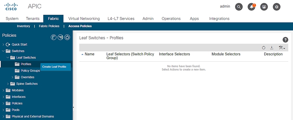
1. Click Fabric and select Access Policies .
2. Expand Switch Policies.
3. Expand Profiles and right-click the Leaf Profiles and select Create Leaf Profile.
Figure 58 Leaf Switch Profile creation
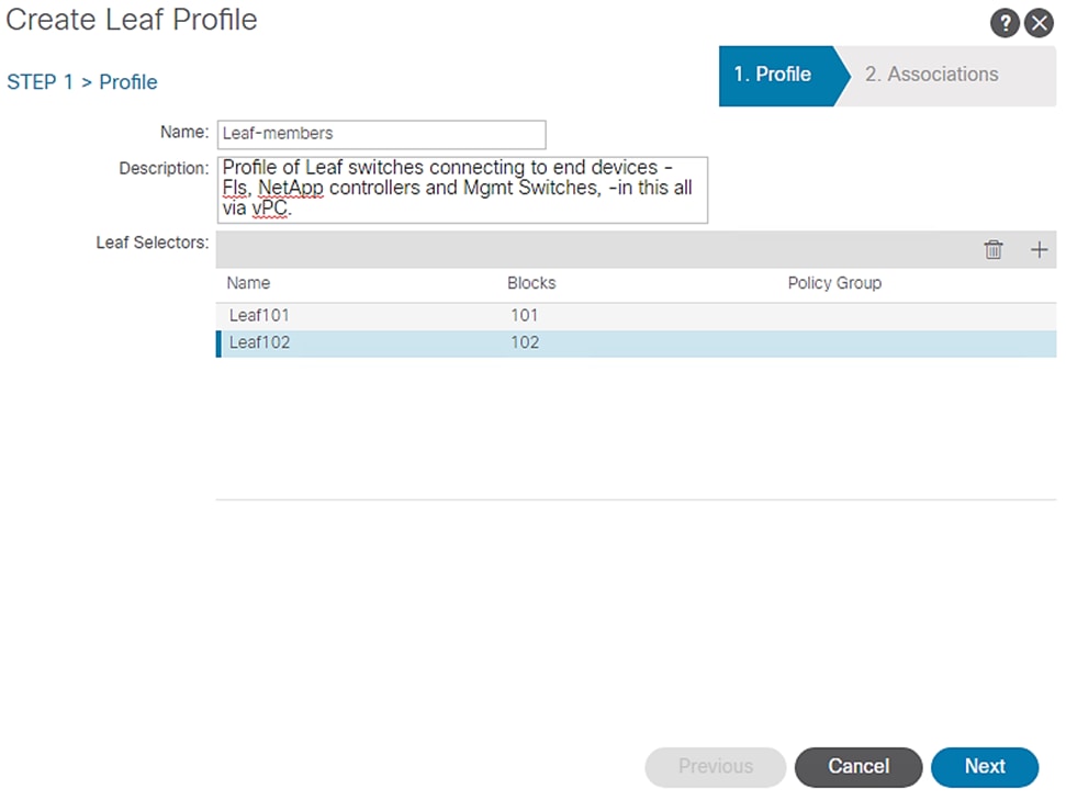
4. Enter Leaf-members as the Name of the Switch Profile.
Figure 59 Switch Profile Configuration
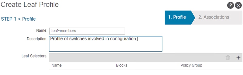
5. Under Leaf Selectors, click the + symbol.
6. Enter Leaf101 in the Name field.
7. Select 101 under BLOCKS.
8. Click UPDATE to save the configuration.
9. Click the + symbol again to add another switch.
10. Enter Leaf102 in the Name field.
11. Select 102 under BLOCKS.
12. Click UPDATE to save the configuration.
Figure 60 Switch Profile Configuration with Leaf Switches
13. Click Next.
14. In the ASSOCIATIONS windows, select all the Interface Profiles created for Interface Selector Profiles.
Figure 61 Switch Profile Association of VPC
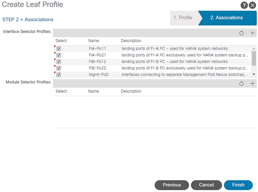
15. Click Finish.
Tenant Configuration
While the Fabric and Access Policies dealt with physical aspects of the fabric setup, Tenant provides for a logical container or a folder for application policies. A Tenant can be seen as representing an actual tenant, a customer installation and at the same time standing for unit of isolation from a policy perspective.
All application configurations in Cisco ACI are part of a tenant. Within a tenant, you define (one or more) Layer 3 networks (VRF instances), one or more bridge domains per network, and EPGs to divide the bridge domains.
![]() We define a SAP HANA customer T01 [T01-HANA] that wants to address a typical HANA Scale-Out system on FlexPod.
We define a SAP HANA customer T01 [T01-HANA] that wants to address a typical HANA Scale-Out system on FlexPod.
Application End Point Group (EPG): An End Point Group (EPG) is a collection of (physical and/or virtual) end points that require common services and policies. An End Point Group example is a set of servers or storage LIFs on a common VLAN providing a common application function or service.
The EPGs are defined based on the following:
· HANA nodes configured with various networks
- Inter-node based on Inter-node network - used by scale out SAP HANA system nodes for inter-node communication
- Mgmt – management interface communication and HANA node administration
- HANA-data, HANA-log, HANA-shared – networks used by HANA nodes for NFS communication for HANA persistence and HANA shared filesystems.
- Backup – for communication between HANA system and backup storage network
- Replication – for communication between HANA system and replication to another HANA system
- AppServer – for communication between HANA system and SAP Application Servers.
- DataSource - for communication between HANA system and external source for data loads
- Client – for user/client software access to HANA system
- iSCSI-A and iSCSI-B – HANA nodes need to use iSCSI boot leveraging iSCSI LUNs from the NetApp array.
· NetApp storage controllers providing via designated networks
- HANA-data, HANA-log and HANA-shared – Data, Log and Hana shared Filesystems provider network on NetApp array.
- iSCSI-A and iSCSI-B – iSCSI service provider network on the array providing boot LUN access.
· Management PoD providing PXE services for HANA nodes.
- Mgmt – Providing access to admin network of SAP HANA landscape from external Management PoD
Application Profile: An application profile models application requirements and contains as many (or as few) End Point Groups (EPGs) as necessary that are logically related to providing the capabilities of an application.
Application Profile: HANA-Multi-host representing a customer T01’s all-encompassing SAP HANA scale out system containing the EPGs as explained above is documented here. A scale-up HANA system configuration would be on the same lines minus the inter-node network.
Bridge Domain: A bridge domain represents a L2 forwarding construct within the fabric. One or more EPG can be associated with one bridge domain or subnet. A bridge domain can have one or more subnets associated with it. One or more bridge domains together form a tenant network.
You can make EPGs that share a mutual need and provide relation, part of the same bridge domain, while you configure it per EPG basis for those that are isolated. To create Bridge Domains, for the SAP HANA scale-out scenario example, define the following BDs containing the EPG combination by following these steps:
1. SAP-connect-dom – set of subnets associated with a common function, connecting to SAP application servers. Client, AppServer and DataSource EPGs are associated with this bridge domain.
2. HANA-data-dom – set of subnets associated with HANA data filesystems provider and consumer functions. EPGs NFS-Data and Node-data are associated with this domain.
3. HANA-log-dom – set of networks associated with HANA log filesystem provider and consumer functions. EPGs NFS-Log and Node-log are associated with this domain.
4. HANA-shared-dom – set of networks associated with HANA shared filesystem provider and consumer functions. EPGs NFS-shared and Node-shared are associated with this domain.
5. iSCSIA-dom – set of networks associated with iSCSI-A booting. EPGs iSCSI-initiatorA and iSCSI-targetA are associated with this domain. Similarly a bridge domain iSCSIB-dom having EPGs iSCSI-initiatorB and iSCSI-targetB associated with it is defined enabling path-B booting.
6. Mgmt-dom – set of networks associated with management access. EPGs Admin and Mgmt-Ext are associated with this domain.
7. HANA-Internal-dom containing the EPG HANA-T01-Internode, associated with inter node communication in the SAP HANA Scale-out cluster.
8. Bkp-dom containing EPG Backup for HANA system backup services.
9. Replication-dom containing EPG Replication.is defined to enable replication services when needed.
Contracts: A service contract can exist between two or more participating peer entities, such as two applications running and communicating with each other behind different endpoint groups, or between providers and consumers, such as a DNS contract between a provider entity and a consumer entity. Contracts utilize filters to limit the traffic between the applications to certain ports and protocols.
You need to create individual contracts between the EPGs that need to talk to each other leveraging the ‘default’ filter that allows all traffic between them.
In the example, since we have client and server networks share the same VLAN IDs and hence subnets, we define them as part of same EPG. Hence, no additional contracts would be needed in this SAP HANA scale out system example.
![]() For a Multi-Tenancy environment, each Tenant can be configured with identical categories, port channels, and so on. However, VLAN use within a tenant would need to be unique between tenants.
For a Multi-Tenancy environment, each Tenant can be configured with identical categories, port channels, and so on. However, VLAN use within a tenant would need to be unique between tenants.
Tenant Creation
To create tenant for SAP HANA, follow these steps:
1. From the main menu, click TENANTS and from the sub-menu click ADD TENANT.
2. In the CREATE TENANT dialog box, type T01-HANA as the name of the tenant.
3. For VRF Name enter T01-HANA-VRF.
Figure 62 Create Tenant
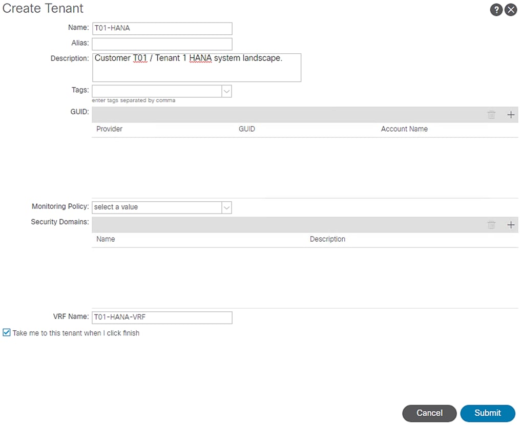
4. Check the ‘Take me to the tenant when I click finish' checkbox.
5. Click Submit.
Application Profiles for HANA
To create HANA-Multi-host Application Profile, follow these steps:
1. Click TENANTS and from the sub-menu click T01-HANA tenant.
2. Expand Tenant T01-HANA in the left pane.
3. Right-click the Application Profiles and click Create Application Profile.
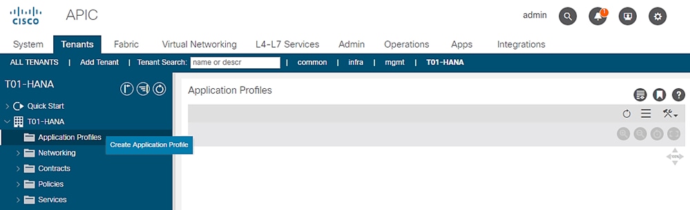
4. In Create Application Profile dialog box, enter HANA-Multi-host in the Name field.
Figure 63 Application Profile HANA-Multi-host
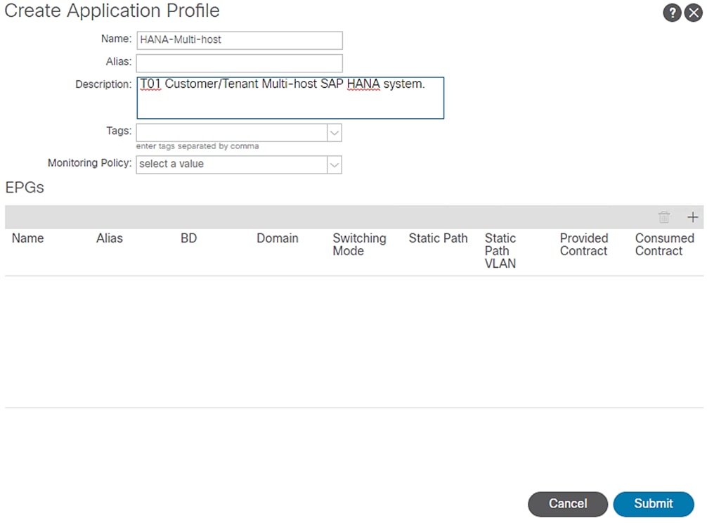
5. Click Submit.
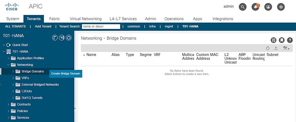
Bridge Domains
To create the planned Bridge Domains for use with HANA-Multi-host Application Profile, follow these steps:
1. Click TENANTS and from the sub-menu click T01-HANA tenant.
2. Expand Tenant T01-HANA.
3. Expand Networking and right-click the Bridge Domains and click Create Bridge Domain.
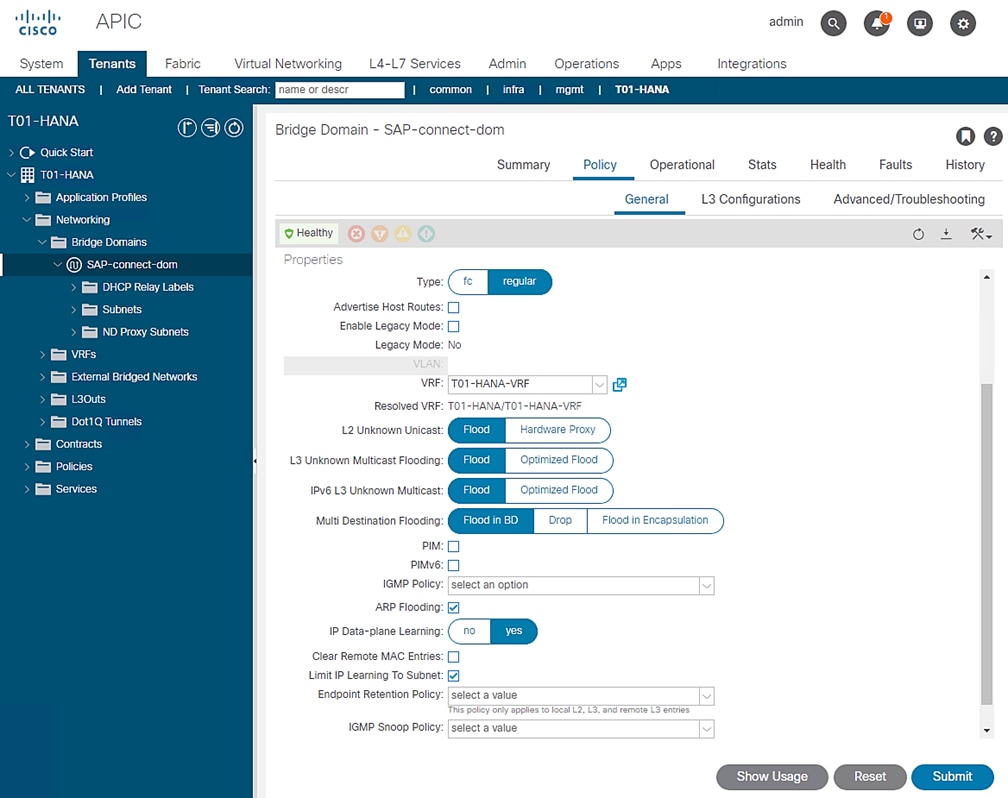
4. In the STEP1>Main page, enter SAP-connect-dom for name and select the previously created T01-HANA/T01-HANA-VRF and click NEXT.
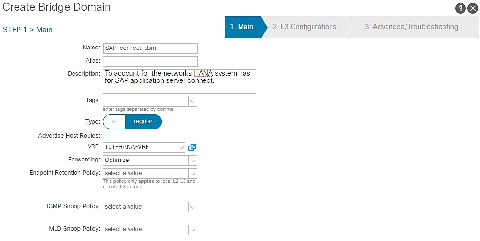
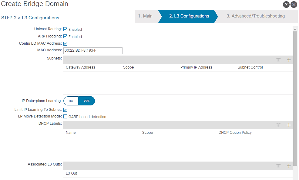
5. In the Step2 > L3 Configurations page, select the default settings. Click NEXT.
6. In the Step3 > Advanced/Troubleshooting page, click FINISH.
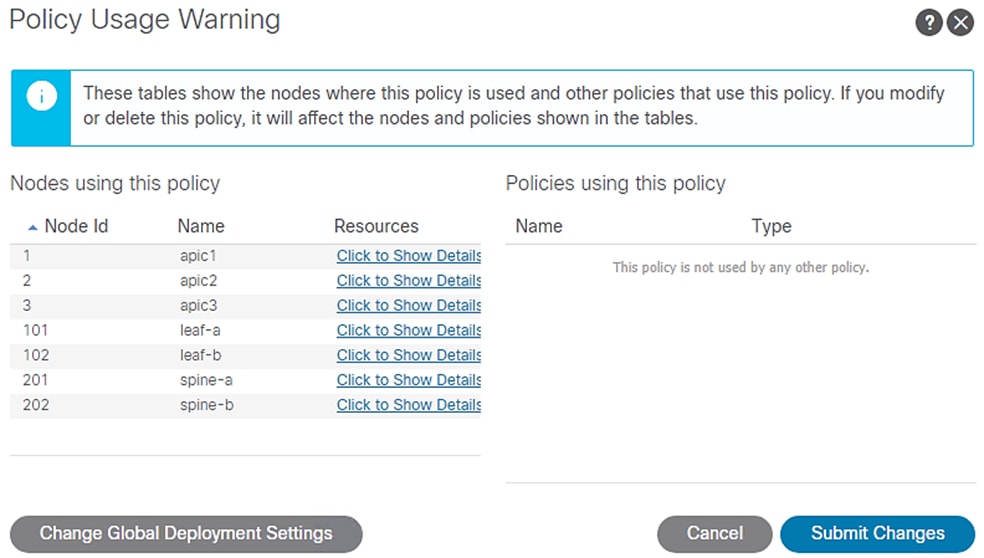
7. Under Bridge Domains, select the created SAP-connect-dom on the left pane. On the right pane, under Policy tab and General sub-tab, change the L2 Unknown Unicast value from Hardware Proxy to Flood. Select Submit. Accept the warning message and click Yes. In the Policy Usage Warning pop-up click Submit Changes.
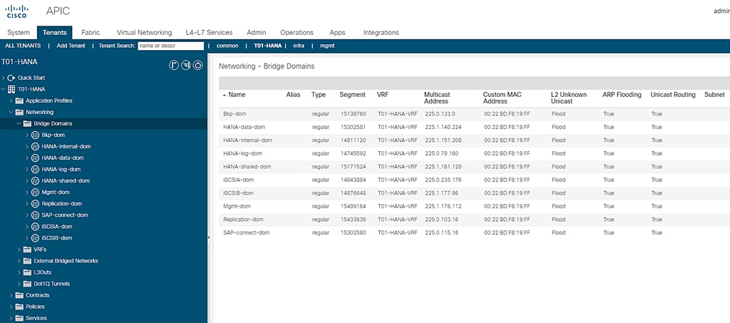
8. Repeat steps 1 through 7 to create the rest of the planned Bridge Domains: HANA-Internal-dom, Bkp-dom, Replication-dom, iSCSIA-dom, iSCSIB-dom, HANA-data-dom, HANA-log-dom, HANA-shared-dom and Mgmt-dom.
![]() Make sure to use HANA-T01-HANA-T01-VRF value on Step1 page and enable ARP Flooding on Step2 page. Selecting the created Bridge Domain, change the L2 Unknown Unicast value from Hardware Proxy to Flood.
Make sure to use HANA-T01-HANA-T01-VRF value on Step1 page and enable ARP Flooding on Step2 page. Selecting the created Bridge Domain, change the L2 Unknown Unicast value from Hardware Proxy to Flood.
Figure 64 Summary of Created Bridge Domains
Application EPGs
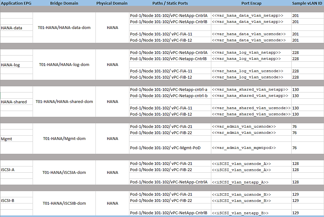
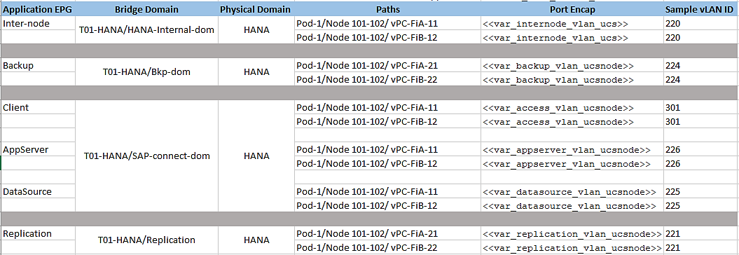
You need to create the EPGs based on the requirements, as detailed in the Tenant Creation section. The table serves as a ready reference for the values for key inputs during the creation of EPGs.
Figure 65 Defined EPGs with Corresponding Bridge Domain Mapping
The steps to create one of EPGs – HANA-data is explained in the following section.
HANA-data EPG
To create the planned Application EPGs, follow these steps:
1. Click TENANTS and from the sub-menu click T01-HANA tenant.
2. Expand Tenant T01-HANA.
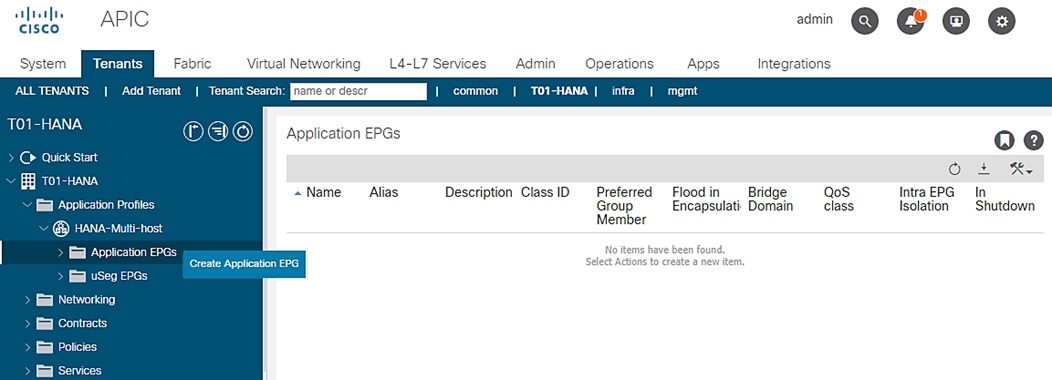
3. Expand Application Profiles, expand HANA-Multi-host, right-click the Application EPGs and click Create Application EPG.
Figure 66 EPG Creation
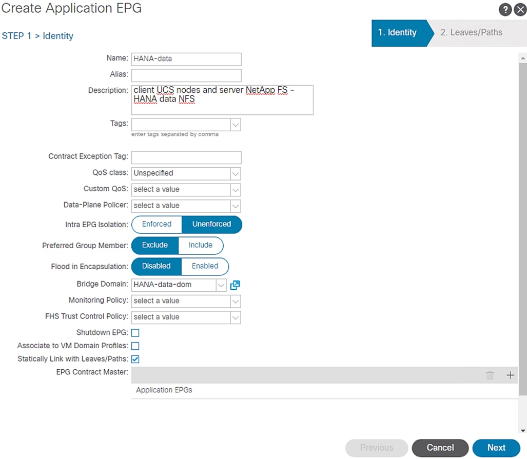
4. In the STEP1>Identity page, enter HANA-data for name and select the previously created Bridge Domain T01-HANA/HANA-data-dom.
5. Enable “Statically Link with Leaves/Paths” option. Click Next.
Figure 67 HANA-data EPG
6. In the STEP2 > Leaves/Paths window, for the Physical Domain, choose HANA from the drop-down list.
7. Under Paths, click + for adding Paths.
8. From the drop-down list for Path, select “Pod-1/Node 101-102/ vPC-NetApp-CntrlA”, set Deployment Immediacy” to Immediate and enter vlan-<<var_hana_data_vlan_netapp>> for “Port Encap” to associate VLAN for HANA-data. Click Update.
9. Under Paths, click + for adding Paths.
10. From the drop-down list for Path, select “Pod-1/Node 101-102/ vPC-NetApp-CntrlB”, set Deployment Immediacy” to Immediate and enter vlan-<<var_hana_data_vlan_netapp>> for “Port Encap” to associate VLAN for HANA-data. Click Update.
11. Under Paths, click + for adding Paths.
12. From the drop-down list for Path, select “Pod-1/Node 101-102/ vPC-FiA-11”, set Deployment Immediacy” to Immediate and enter vlan-<<var_hana_data_vlan_ucsnode>> for “Port Encap” to associate VLAN for NFS-data. Click Update.
13. Again click + for adding Paths.
14. From the drop-down list for Path, select “Pod-1/Node 101-102/ vPC-FiB-12”, set Deployment Immediacy” to Immediate and enter vlan-<<var_hana_data_vlan_ucsnode>> for “Port Encap” to associate VLAN for NFS-data. Click Update.
Figure 68 HANA-data EPG Statically Linking Paths and Assigning Port Encap / VLAN Information
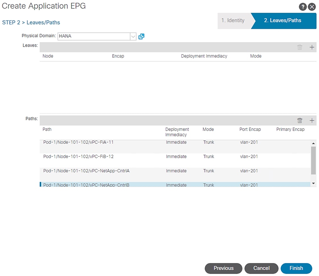
15. Click Finish.
![]() Repeat the sequence of steps substituting the input values from the reference table above to create rest of the EPGs.
Repeat the sequence of steps substituting the input values from the reference table above to create rest of the EPGs.
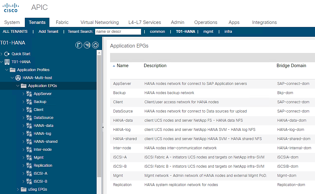
To summarize, at the end of this section, you will have created the following EPGs.
Figure 69 Summary of EPGs (with their Bridge Domain assignment) Created
Server Configuration
The SAP HANA TDI option enables multiple SAP HANA production systems to run on the same infrastructure. In this configuration, the existing blade servers used by different SAP HANA systems share the same network infrastructure and storage systems. In addition, the SAP application server can share the same infrastructure as the SAP HANA database.
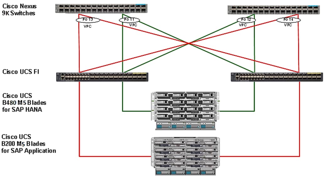
Cisco UCS servers enable separation of traffic, between a SAP HANA system and a non-SAP HANA system. This is achieved by creating a separate network uplink port-channel on Cisco UCS 6454 Fabric Interconnects, for each system type using the VLAN group option. This approach will guarantee the network bandwidth for each tenant in a secured environment, Figure 70 shows an example configuration of this approach. In this example, two port-channels on each of the Cisco UCS Fabric Interconnects are created:
· Port-channel 11 and 13 are created on Cisco UCS Fabric Interconnect A
· Port-channel 12 and 14 are created on Cisco UCS Fabric Interconnect B
Optionally, a VLAN group for SAP HANA is created and all the VLANs carrying traffic for SAP HANA is added to this VLAN group. This VLAN group can be assigned to use port-channel 11 on Cisco UCS Fabric Interconnect A and port-channel 12 on Cisco UCS Fabric Interconnect B.
Similarly, a VLAN group for application servers or for backup network can be created and all the VLANs carrying traffic for this use-case. The VLAN group can then be assigned to use port-channel 13 on fabric interconnect A and port-channel 14 on fabric interconnect B.
This approach achieves bandwidth-separation between SAP HANA servers and applications servers or backup management use case and bandwidth for SAP HANA servers can be increased or decreased by altering the number of ports in the port-channel 11 and port-channel 12.
Figure 70 Network Separation of Multiple Systems Using Port-Channel and VLAN Groups
Cisco UCS Base Configuration
This section describes the specific configurations on Cisco UCS servers to address SAP HANA requirements.
Initial Setup of Cisco UCS 6454 Fabric Interconnects
This section provides the detailed procedures to configure the Cisco Unified Computing System (Cisco UCS) for use in FlexPod Datacenter Solution for SAP HANA environment. These steps are necessary to provision the Cisco UCS C-Series and B-Series servers to meet SAP HANA requirements.
Cisco UCS 6454 Fabric Interconnect A
To configure the Cisco UCS Fabric Interconnect A, follow these steps:
1. Connect to the console port on the first Cisco UCS 6454 Fabric Interconnect.
Enter the configuration method: console
Enter the setup mode; setup newly or restore from backup.(setup/restore)? setup
You have choosen to setup a a new fabric interconnect? Continue? (y/n): y
Enforce strong passwords? (y/n) [y]: y
Enter the password for "admin": <<var_password>>
Enter the same password for "admin": <<var_password>>
Is this fabric interconnect part of a cluster (select 'no' for standalone)? (yes/no) [n]: y
Which switch fabric (A|B): A
Enter the system name: <<var_ucs_clustername>>
Physical switch Mgmt0 IPv4 address: <<var_ucsa_mgmt_ip>>
Physical switch Mgmt0 IPv4 netmask: <<var_ucsa_mgmt_mask>>
IPv4 address of the default gateway: <<var_ucsa_mgmt_gateway>>
Cluster IPv4 address: <<var_ucs_cluster_ip>>
Configure DNS Server IPv4 address? (yes/no) [no]: y
DNS IPv4 address: <<var_nameserver_ip>>
Configure the default domain name? y
Default domain name: <<var_dns_domain_name>>
Join centralized management environment (UCS Central)? (yes/no) [n]: Enter
2. Review the settings printed to the console. If they are correct, answer yes to apply and save the configuration.
3. Wait for the login prompt to make sure that the configuration has been saved.
Cisco UCS 6454 Fabric Interconnect B
To configure the Cisco UCS Fabric Interconnect B, follow these steps:
1. Connect to the console port on the second Cisco UCS 6454 fabric interconnect.
Enter the configuration method: console
Installer has detected the presence of a peer Fabric interconnect. This Fabric interconnect will be added to the cluster. Do you want to continue {y|n}? y
Enter the admin password for the peer fabric interconnect: <<var_password>>
Physical switch Mgmt0 IPv4 address: <<var_ucsb_mgmt_ip>>
Apply and save the configuration (select ‘no’ if you want to re-enter)? (yes/no): y
2. Wait for the login prompt to make sure that the configuration has been saved.
Log into Cisco UCS Manager
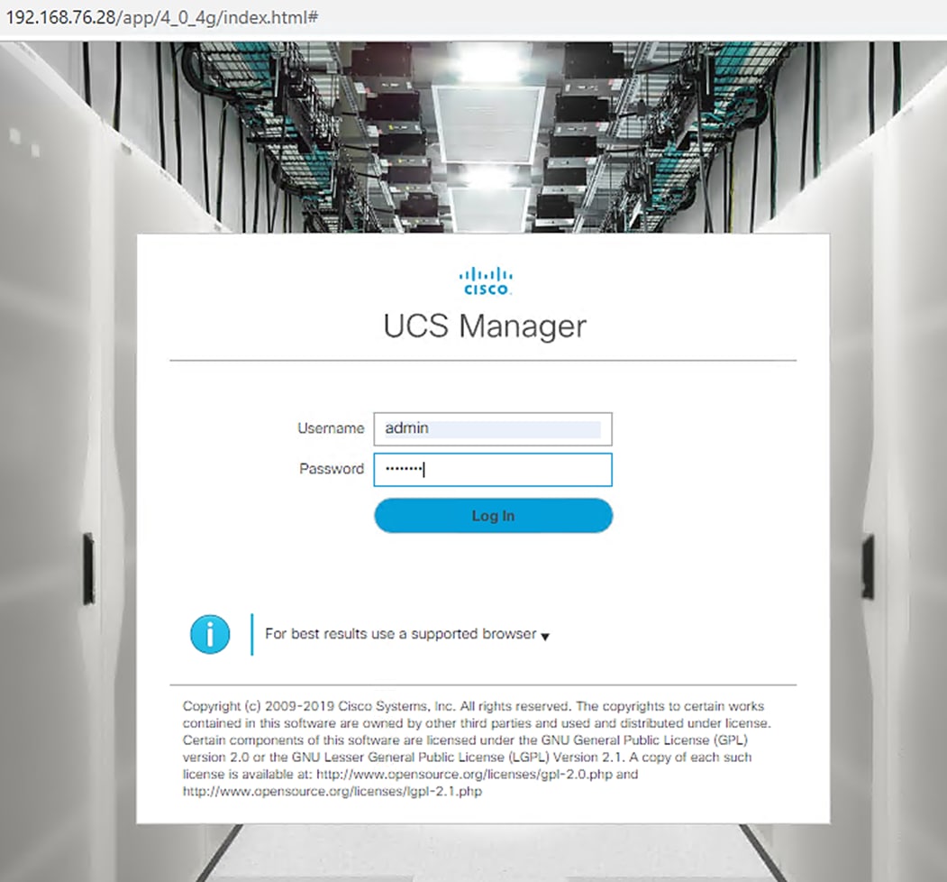
To log into the Cisco Unified Computing System (UCS) environment, follow these steps:
1. Open a web browser and navigate to the Cisco UCS 6454 Fabric Interconnect cluster address.
2. Click the Launch UCS Manager link to download the Cisco UCS Manager software.
3. If prompted to accept security certificates, accept as necessary.
4. When prompted, enter admin as the user name and enter the administrative password.
5. Click Login to log into Cisco UCS Manager.
Upgrade Cisco UCS Manager Software to Version 4.0(4g)
This document assumes the use of Cisco UCS Manager Software version 4.0(4g). To upgrade the Cisco UCS Manager software and the Cisco UCS 6454 Fabric Interconnect software to version 4.0(4g), refer to the Cisco UCS Manager Install and Upgrade Guides.
Add Block of IP Addresses for KVM Access
To create a block of IP addresses for server Keyboard, Video, Mouse (KVM) access in the Cisco UCS environment, follow these steps:
1. This block of IP addresses should be in the same subnet as the management IP addresses for the Cisco UCS Manager.
2. In Cisco UCS Manager, click the LAN tab in the navigation pane.
3. Select Pools > root > IP Pools > IP Pool ext-mgmt.
4. In the Actions pane, select Create Block of IP Addresses.
5. Enter the starting IP address of the block and the number of IP addresses required, and the subnet and gateway information.
6. Click OK to create the IP block.
7. Click OK in the confirmation message.
Synchronize Cisco UCS to NTP
To synchronize the Cisco UCS environment to the NTP server, follow these steps:
1. In Cisco UCS Manager, click the Admin tab in the navigation pane.
2. Select All > Timezone Management.
3. In the Properties pane, select the appropriate time zone in the Timezone menu.
4. Click Save Changes and then click OK.
5. Click Add NTP Server.
6. Enter <<var_global_ntp_server_ip>> and click OK.
7. Click OK.
Cisco UCS Blade Chassis Connection Options
For the Cisco UCS 2408 Series Fabric Extenders, two configuration options are available: pinning and port-channel.
SAP HANA node communicates with every other SAP HANA node using multiple I/O streams and this makes the port-channel option a highly suitable configuration.
Edit Chassis Discovery Policy
Setting the discovery policy simplifies the addition of Cisco UCS B-Series chassis and of additional fabric extenders for further Cisco UCS C-Series connectivity.
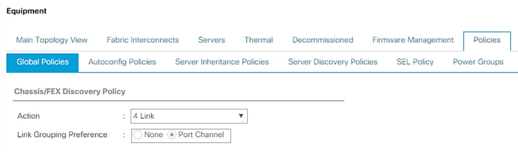
To modify the chassis discovery policy, follow these steps:
1. In Cisco UCS Manager, click the Equipment tab in the navigation pane and select Equipment in the list on the left.
2. In the right pane, click the Policies tab.
3. Under Global Policies, set the Chassis/FEX Discovery Policy to match the number of uplink ports that are cabled between the chassis / fabric extenders (FEX) and the fabric interconnects.
4. Set the Link Grouping Preference to “Port Channel” for Port Channel.
5. Click Save Changes.
6. Click OK.
Enable Server and Uplink Ports
To enable server and uplink ports, follow these steps:
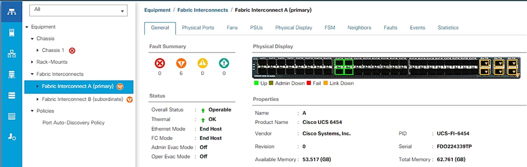
1. In Cisco UCS Manager, click the Equipment tab in the navigation pane.
2. Select Equipment > Fabric Interconnects > Fabric Interconnect A (primary) > Fixed Module.
3. Expand Ethernet Ports.
4. Select the ports that are connected to the chassis and / or to the Cisco C-Series Server (4 per FI in our case), right-click them, and select Configure as Server Port.
5. Click Yes to confirm server ports and click OK.
6. Verify that the ports connected to the chassis and / or to the Cisco C-Series Server are now configured as server ports. In the validation setup - Eth ports 1/17 through 1/20 on FI-A and FI-B are connected to the chassis. Right click these ports and “Configure as Server Port”.
7. Select ports that are connected to the Cisco Nexus ACI switches, right-click them, and select “Configure as Uplink Port”. In the validation setup, this is done for the eth ports 1/49 through 1/54 in this setup.
8. Click Yes to confirm uplink ports and click OK.
9. Select Equipment > Fabric Interconnects > Fabric Interconnect B (subordinate) > Fixed Module.
10. Expand Ethernet Ports.
11. Select the ports that are connected to the chassis or to the Cisco C-Series Server (two per FI), right-click them, and select Configure as Server Port.
12. Click Yes to confirm server ports and click OK.
13. Select ports that are connected to the Cisco Nexus switches, right-click them and select Configure as Uplink Port.
14. Click Yes to confirm the uplink ports and click OK.
Acknowledge Cisco UCS Chassis and Rack-Mount Servers
To acknowledge all Cisco UCS chassis and Rack Mount Servers, follow these steps:
1. In Cisco UCS Manager, click the Equipment tab in the navigation pane.
2. Expand Chassis and select each chassis that is listed.
3. Right-click each chassis and select Acknowledge Chassis.
4. Click Yes and then click OK to complete acknowledging the chassis.
5. If C-Series servers are a part of the configuration, expand Rack Mounts and FEX.
6. Right-click each Server that is listed and select Acknowledge Server.
7. Click Yes and then click OK to complete acknowledging the Rack Mount Servers.
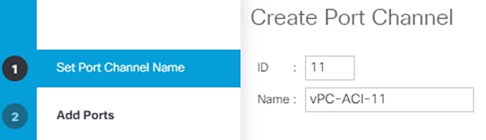
Create Uplink Port Channels to Cisco ACI Leaf Switches
An uplink port channel 11 on Fi-A and port channel 12 on FI-B with 4 ports eth 1/51-1/54 is defined to carry all the SAP HANA networks traffic. We are using 4 x 40GbE ports for this port channel providing 160Gbps operational speed and is good for carrying all the HANA networks traffic.
Another port channel 21 on FI- A and port channel 22 on FI-B with 2 ports eth 1/49-1/50 is configured for exclusive usage by backup traffic, iSCSI boot network and HANA node admin network, for example. This 2 x 40GbE port channel providing 80Gbps operational speed should suffice for the same.
![]() While the Cisco UCS 6454 FI uplink ports and corresponding ports on Cisco Nexus 9336C-FX2 leaves support both 40GbE and 100GbE speeds, we had 40GbE compatible cables in the validation setup and hence the testing has been done with 40GbE.
While the Cisco UCS 6454 FI uplink ports and corresponding ports on Cisco Nexus 9336C-FX2 leaves support both 40GbE and 100GbE speeds, we had 40GbE compatible cables in the validation setup and hence the testing has been done with 40GbE.
Additional port channels for other specific traffic usage, if any, can be configured on need basis.
To configure the necessary port channels as planned above for the Cisco UCS environment, follow these steps:
1. In Cisco UCS Manager, click the LAN tab in the navigation pane.
2. In this procedure, two port channels are created: one from fabric A to both Cisco Nexus switches and one from fabric B to both Cisco Nexus switches.
3. Under LAN > LAN Cloud, expand the Fabric A tree.
4. Right-click Port Channels.
5. Select Create Port Channel.
6. Enter 11 as the unique ID of the port channel.
7. Enter vPC-ACI-11-Nexus as the name of the port channel.
8. Click Next.
9. Select the following ports to be added to the Port Channel:
· Slot ID 1 and port 51
· Slot ID 1 and port 52
· Slot ID 1 and port 53
· Slot ID 1 and port 54
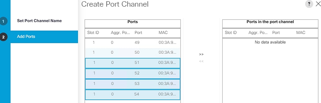
10. Click >> to add the ports to the port channel.
11. Click Finish to create the port channel.
12. Click OK.
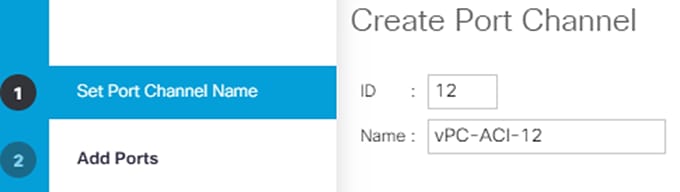
13. In the navigation pane, under LAN > LAN Cloud, expand the fabric B tree:
a. Right-click Port Channels.
b. Select Create Port Channel.
c. Enter 12 as the unique ID of the port channel.
d. Enter vPC-ACI-12 as the name of the port channel.
14. Click Next.
15. Select the following ports to be added to the port channel:
· Slot ID 1 and port 51
· Slot ID 1 and port 52
· Slot ID 1 and port 53
· Slot ID 1 and port 54
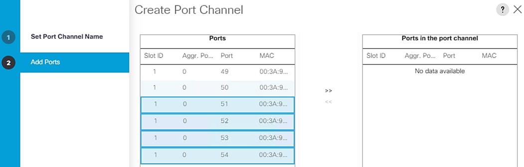
16. Click >> to add the ports to the port channel.
17. Click Finish to create the port channel.
18. Click OK.
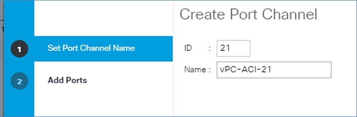
To create another port-channel pair on FIs for backup, iSCSI boot, replication and HANA node admin networks, follow these steps:
1. In Cisco UCS Manager, click the LAN tab in the navigation pane.
2. Under LAN > LAN Cloud, expand the Fabric A tree.
3. Right-click Port Channels.
4. Select Create Port Channel.
5. Enter 21 as the unique ID of the port channel.
6. Enter vPC-ACI-21 as the name of the port channel.
7. Click Next.
8. Select the following ports to be added to the port channel:
· Slot ID 1 and port 49
· Slot ID 1 and port 50
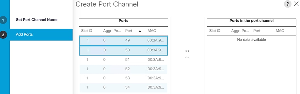
9. Click >> to add the ports to the port channel.
10. Click Finish to create the port channel.
11. Click OK.
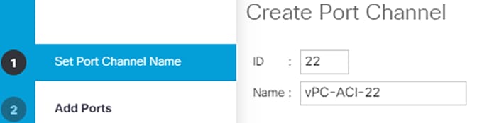
12. In the navigation pane, under LAN > LAN Cloud, expand the fabric B tree.
13. Right-click Port Channels.
14. Select Create Port Channel.
15. Enter 22 as the unique ID of the port channel.
16. Enter vPC-ACI 22 as the name of the port channel.
17. Click Next.
18. Select the following ports to be added to the port channel:
· Slot ID 1 and port 49
· Slot ID 1 and port 50
19. Click >> to add the ports to the port channel.
20. Click Finish to create the port channel.
21. Click OK.
![]() Check for the cable used and set the admin speed for the Port Channels accordingly instead of default Auto setting. In the validation setup, since 40G cables were used for connectivity, the 40G Link Level policy was applied to the policy group assigned to leaf interfaces and so were the port channels’ admin speed.
Check for the cable used and set the admin speed for the Port Channels accordingly instead of default Auto setting. In the validation setup, since 40G cables were used for connectivity, the 40G Link Level policy was applied to the policy group assigned to leaf interfaces and so were the port channels’ admin speed.
Create New Organization
For secure multi-tenancy within the Cisco UCS domain, a logical entity is created as Organization.
To create organization unit, follow these steps:
1. In Cisco UCS Manager, from the Servers bar, select Servers and right-click root and select Create Organization.
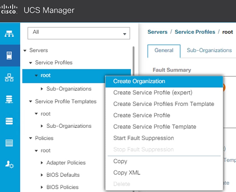
2. Enter the Name as T01-HANA.
3. Optional Enter the Description as Org for T01-HANA.
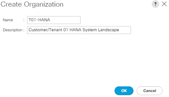
4. Click OK to create the Organization.
Create MAC Address Pools
In this procedure, two MAC address pools are created, one for each switching fabric. To configure the necessary MAC address pools for the Cisco UCS environment, follow these steps:
1. In Cisco UCS Manager, click the LAN tab in the navigation pane.
2. Select Pools > root> Sub-Organizations> T01-HANA.
3. Right-click MAC Pools and select Create MAC Pool to create the MAC address pool .
4. Enter T01-pathA as the name of the MAC pool. Optional: Enter a description for the MAC pool.
5. Choose Assignment Order Sequential.
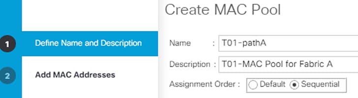
6. Click Next.
7. Click Add.
8. Specify a starting MAC address.
9. It may be helpful to have AA for the fourth octet of the starting MAC address to identify all of the MAC addresses as Fabric Interconnect A addresses.
10. Specify a size for the MAC address pool that is sufficient to support the available blade or server resources.
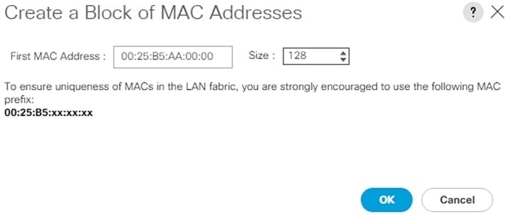
11. Click OK.
12. Click Finish.
13. In the confirmation message, click OK.
14. Right-click MAC Pools again under the T01-HANA Sub-organization.
15. Select Create MAC Pool to create another MAC address pool.
16. Enter T01-pathB as the name of the MAC pool.
17. Optional: Enter a description for the MAC pool.

18. Click Next.
19. Click Add.
20. Specify a starting MAC address.
21. It may be helpful to have BB for the fourth octet of the starting MAC address to identify all of the MAC addresses as Fabric Interconnect A addresses. Specify a size for the MAC address pool that is sufficient to support the available blade or server resources.
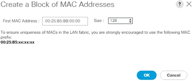
22. Click OK.
23. Click Finish.
24. In the confirmation message, click OK.
Create UUID Suffix Pool
To configure the necessary universally unique identifier (UUID) suffix pool for the Cisco UCS environment, follow these steps:
1. In Cisco UCS Manager, click the Servers tab in the navigation pane.
2. Select Pools > root > Sub-Organizations> T01-HANA.
3. Right-click UUID Suffix Pools. Select Create UUID Suffix Pool.
4. Enter T01-UUID as the name of the UUID suffix pool.
5. Optional: Enter a description for the UUID suffix pool.
6. Keep the Prefix as the Derived option.
7. Select Sequential for Assignment Order.
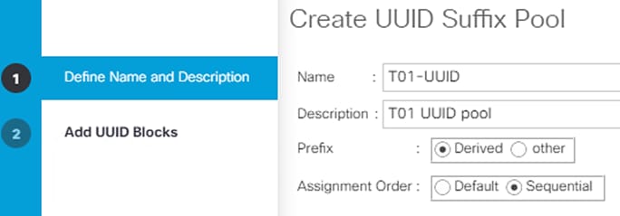
8. Click Next.
9. Click Add to add a block of UUIDs.
10. Keep the From field at the default setting.
11. Specify a size for the UUID block that is sufficient to support the available blade or server resources.

12. Click OK.
13. Click Finish.
14. Click OK.
Create IQN Pools for iSCSI Boot
To configure the necessary IQN pools for the Cisco UCS environment, follow these steps:
1. In Cisco UCS Manager, click SAN.
2. Expand Pools > root> Sub-Organizations> T01-HANA.
3. Right-click IQN Pools.
4. Select Create IQN Suffix Pool to create the IQN pool.
5. Enter IQN-HANA for the name of the IQN pool.
6. Optional: Enter a description for the IQN pool.
7. Enter iqn.2020-03.com.flexpod as the prefix.
8. Select Sequential for Assignment Order.
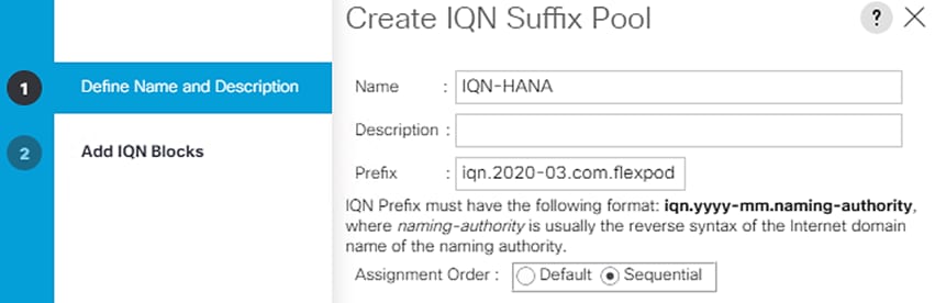
9. Click Next.
10. Click Add.
11. Enter hana-node as the suffix.
12. Enter 1 in the From field.
13. Specify the size of the IQN block sufficient to support the available server resources.

14. Click OK.
15. Click Finish and OK to complete creating the IQN pool.
Create IP Pools for iSCSI Boot
To configure the necessary IP pools iSCSI boot for the Cisco UCS environment within the HANA Organization, follow these steps:
1. In Cisco UCS Manager, click LAN.
2. Expand Pools > root > Sub-Organizations > T01-HANA Organization.
3. Right-click IP Pools under the HANA Organization.
4. Select Create IP Pool.
5. Enter iSCSI-IP-Pool-A as the name of IP pool.
6. Optional: Enter a description for the IP pool.
7. Select Sequential for the assignment order.
8. Click Next.
9. Click Add to add a block of IP addresses.
10. In the From field, enter the beginning of the range to assign as iSCSI boot IP addresses on Fabric A.
11. Set the size to enough addresses to accommodate the servers.
12. Enter the appropriate Subnet Mask.
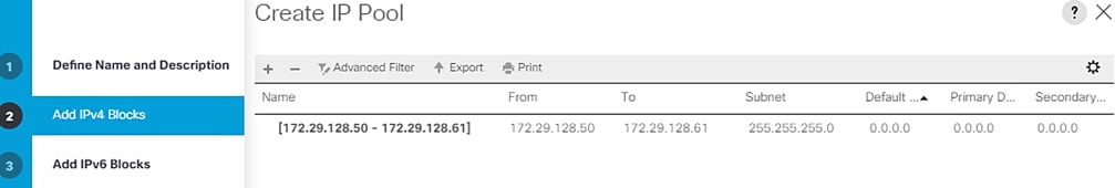
13. Click OK.
14. Click Next.
15. Click Finish and OK to complete creating the Fabric A iSCSI IP Pool.
16. Right-click IP Pools again under the T01-HANA Sub-Organization.
17. Select Create IP Pool.
18. Enter iSCSI-IP-Pool-B as the name of IP pool.
19. Optional: Enter a description for the IP pool.
20. Select Sequential for the assignment order.
21. Click Next.
22. Click Add to add a block of IP addresses.
23. In the From field, enter the beginning of the range to assign as iSCSI IP addresses on Fabric B.
24. Set the size to enough addresses to accommodate the servers.
25. Enter the appropriate Subnet Mask.
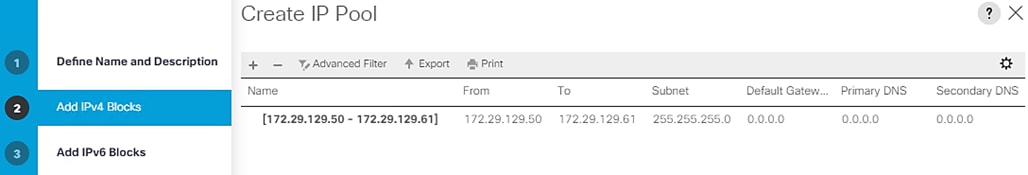
26. Click OK.
27. Click Next.
28. Click Finish and OK to complete creating the Fabric B iSCSI IP Pool.
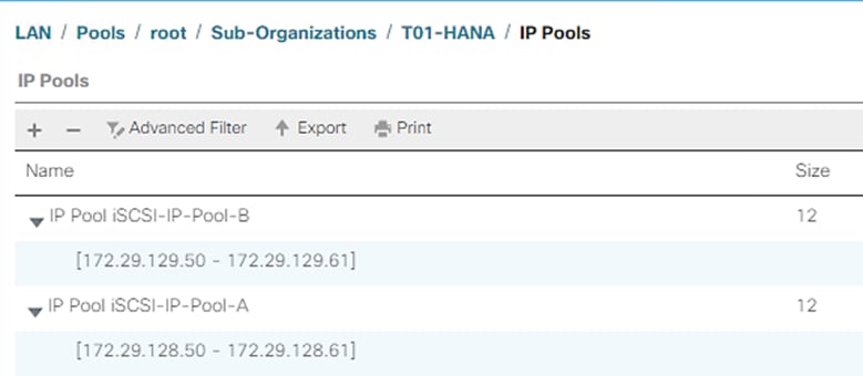
Power Policy
To run Cisco UCS with two independent power distribution units, the redundancy must be configured as Grid. Follow these steps:
1. In Cisco UCS Manager, click the Equipment tab in the navigation pane and select Equipment in the list on the left.
2. In the right pane, click the Policies tab.
3. Under Global Policies, set the Power Policy to “Grid.”
4. Click Save Changes.
5. Click OK.
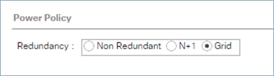
Power Control Policy
The Power Capping feature in Cisco UCS is designed to save power with a legacy data center use-cases. This feature does not contribute much to the high performance behavior of SAP HANA. By choosing the option “No Cap” for power control policy, the SAP HANA server nodes will not have a restricted power supply. It is recommended to have this power control policy to ensure sufficient power supply for high performance and critical applications like SAP HANA.
To create a power control policy for the Cisco UCS environment, follow these steps:
1. In Cisco UCS Manager, click the Servers tab in the navigation pane.
2. Select Policies > root.
3. Right-click Power Control Policies.
4. Select Create Power Control Policy.
5. Enter HANA as the power control policy name.
6. Change the power capping setting to No Cap.
7. Click OK to create the power control policy.
8. Click OK.
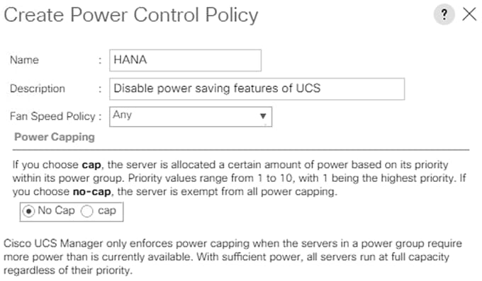
Create Network Control Policy
To create a network control policy that enables CDP and LLDP on server virtual network controller (vNIC) ports, follow these steps:
1. In Cisco UCS Manager, click LAN.
2. Expand Policies > root> Sub-Organizations> T01-HANA.
3. Right-click Network Control Policies.
4. Select Create Network Control Policy.
5. Enter Enable-CDP-LLDP as the policy name.
6. For CDP, select the Enabled option. For LLDP, scroll down and select Enabled for both Transmit and Receive.
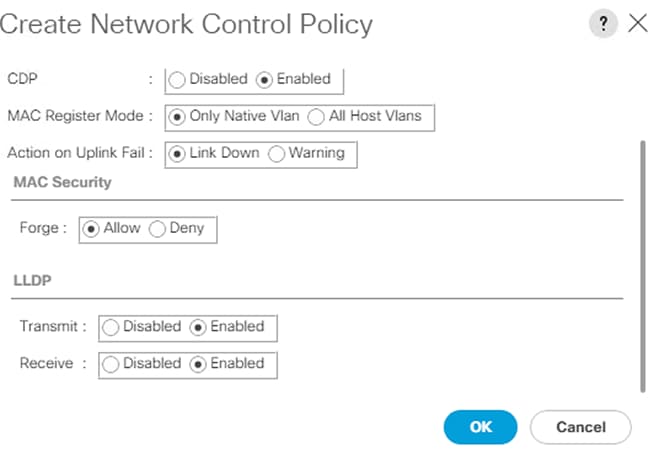
7. Click OK to create the Enable-CDP-LLDP policy.
Create Host Firmware Package
Firmware management policies allow the administrator to select the corresponding packages for a given server configuration. These policies often include packages for adapter, BIOS, board controller, FC adapters, host bus adapter (HBA) option ROM, and storage controller properties.
To create a firmware management policy for a given server configuration in the Cisco UCS environment, follow these steps:
1. In Cisco UCS Manager, click the Servers tab in the navigation pane.
2. Select Policies > root.
3. Right-click Host Firmware Packages. Select Create Host Firmware Package.
4. Enter HANA-Nodes-FW as the name of the host firmware package.
5. Leave Simple selected.
6. Select the version 4.0(4g) packages for both the Blade and Rack Packages.
7. Click OK to create the host firmware package.
8. Click OK.
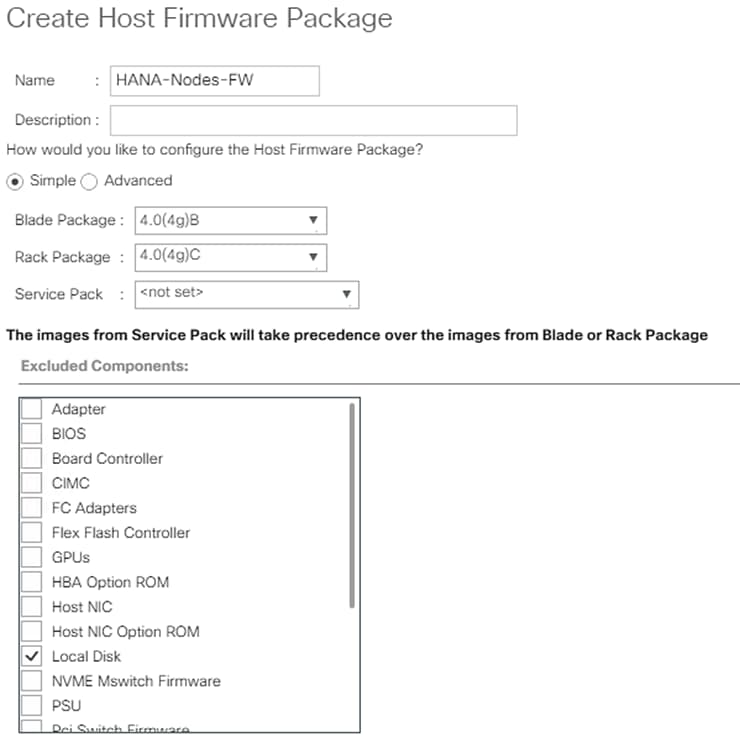
Create Local Disk Configuration Policy (Optional)
A local disk configuration for the Cisco UCS environment is necessary if the servers in the environment do not have a local disk.
![]() This policy should not be used on servers that contain local disks.
This policy should not be used on servers that contain local disks.
To create a local disk configuration policy, follow these steps:
1. In Cisco UCS Manager, click the Servers tab in the navigation pane.
2. Select Policies > root.
3. Right-click Local Disk Config Policies. Select Create Local Disk Configuration Policy.
4. Enter No-local as the local disk configuration policy name.
5. Change the mode to No Local Storage.
6. Click OK to create the local disk configuration policy.
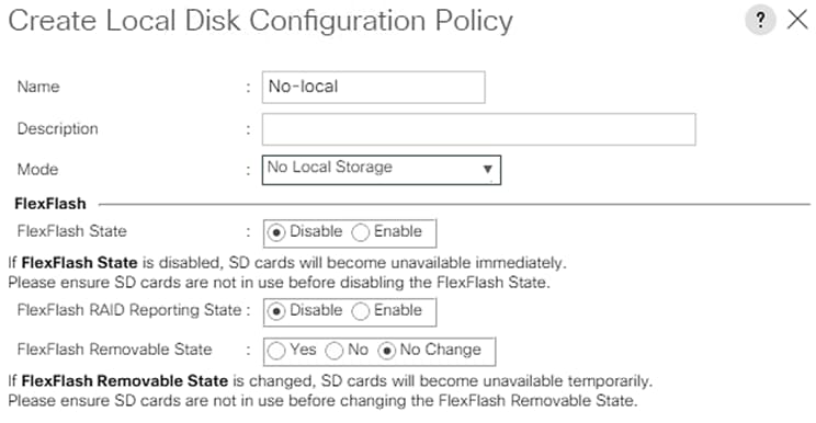
7. Click OK.
Create Server BIOS Policy
![]() For more information, refer to the Performance Tuning Guide for Cisco UCS M5 Servers whitepaper.
For more information, refer to the Performance Tuning Guide for Cisco UCS M5 Servers whitepaper.
1. In Cisco UCS Manager, click the Servers tab in the navigation pane.
2. Choose Policies > root > Sub-Organization > T01-HANA.
3. Right-click BIOS Policies. Choose Create BIOS Policy.
4. Enter HANA as the BIOS policy name.
5. Click OK.
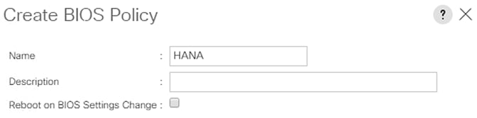
6. Under BIOS Policies, click the newly created HANA Policy.
7. In the Main pane, under BIOS Setting choose Disabled for Quiet Boot.
8. Click the Advance tab.
![]() CPU C-States are idle power saving states. The recommendation from SAP for SAP HANA is to allow C0 and C1 states, but to disable higher C-States. This will force the CPU Core to either operate on its maximum frequency or to transition to its minimum frequency when idle.
CPU C-States are idle power saving states. The recommendation from SAP for SAP HANA is to allow C0 and C1 states, but to disable higher C-States. This will force the CPU Core to either operate on its maximum frequency or to transition to its minimum frequency when idle.
9. Under Processor choose Custom for Power Technology and enable “C0 C1 State” for Package C State Limit option.
10. Set IO sensitive for Workload Configuration.
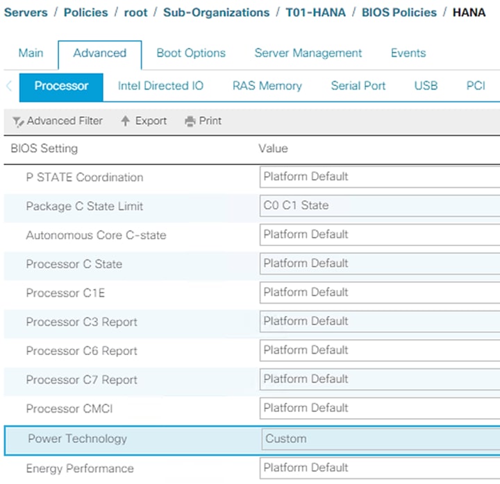

11. Click RAS Memory.
12. Choose Platform Default for Memory RAS Configuration and Enabled for NUMA optimized.
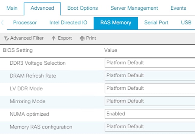
13. Click Serial Port.
14. Choose Enabled for Serial Port A enable.
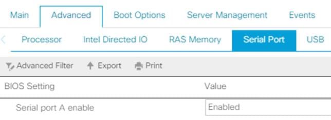
15. Click Server Management.
16. Choose 115.2k for BAUD Rate, Enabled for Legacy OS redirection, VT100-PLUS for Terminal type. This is used for Serial Console Access over LAN to all SAP HANA servers.
17. Click Save Changes.
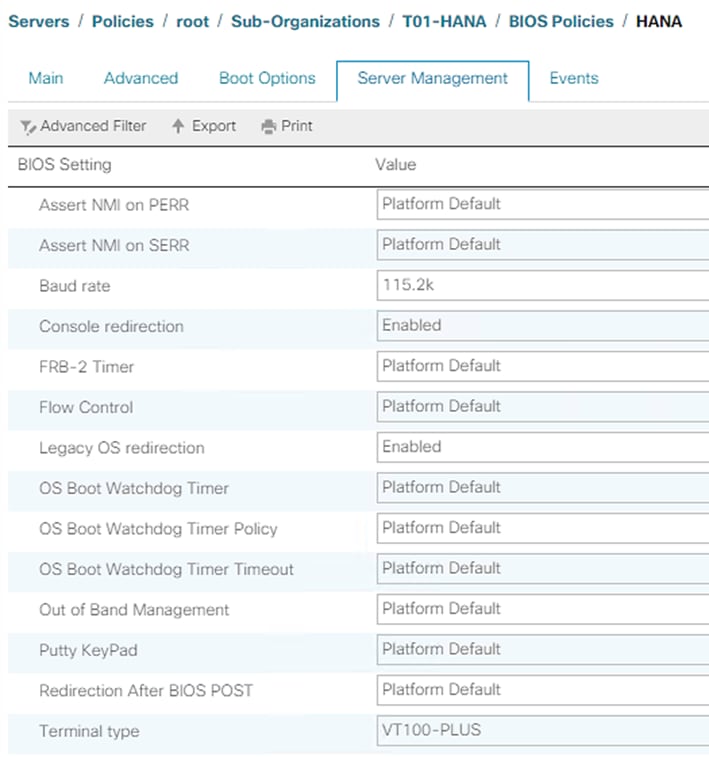
Create Serial Over LAN Policy
The Serial over LAN policy is required to get console access to all the SAP HANA servers through SSH from the management network. This is used if the server hangs or there is a Linux kernel crash, where the dump is required. To configure the speed in the Server Management tab of the BIOS Policy, follow these steps:
1. In Cisco UCS Manager, click the Servers tab in the navigation pane.
2. Select Policies > root > Sub-Organization > T01-HANA.
3. Right-click Serial over LAN Policies.
4. Select Create Serial over LAN Policy.
5. Enter SoL-Console as the Policy name.
6. Select Serial over LAN State to enable.
7. Change the Speed to 115200.
8. Click OK.
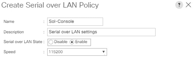
Update Default Maintenance Policy
It is recommended to update the default Maintenance Policy with the Reboot Policy “User Ack” for the SAP HANA server. This policy will wait for the administrator to acknowledge the server reboot for the configuration changes to take effect.
To update the default Maintenance Policy, follow these steps:
1. In Cisco UCS Manager, click the Servers tab in the navigation pane.
2. Select Policies > root.
3. Select Maintenance Policies > default.
4. Change the Reboot Policy to User Ack.
5. Click Save Changes.
6. Click OK to accept the change.
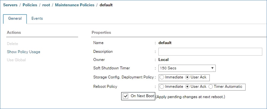
Adapter Policy Configuration – HANA
This section describes the Ethernet Adapter Policy with optimized Interrupts values. This policy must be used for the SAP HANA internal network to provide best network performance.
To create an Ethernet Adapter Policy, follow these steps:
1. In Cisco UCS Manager, click the Servers tab in the navigation pane.
2. Select Policies > root > Sub-Organization > T01-HANA.
3. Right-click Adapter Policies.
4. Select Create Ethernet Adapter Policy.
5. Enter HANA as the Ethernet Adapter policy name.
6. Expand Resources:
a. Change the Transmit Queues to 8
b. Change Ring size to 4096
c. Change the Receive Queues to 8
d. Change Ring size to 4096
e. Change the Completion Queue to 16
f. Change the Interrupts to 32
7. Expand Options > Change Receive Side Scaling (RSS) to Enabled.
8. Change Accelerated Receive Flow Steering to Disabled.
9. For the rest of parameters maintain default.
10. Click OK to create the Ethernet Adapter policy.
11. Click OK.
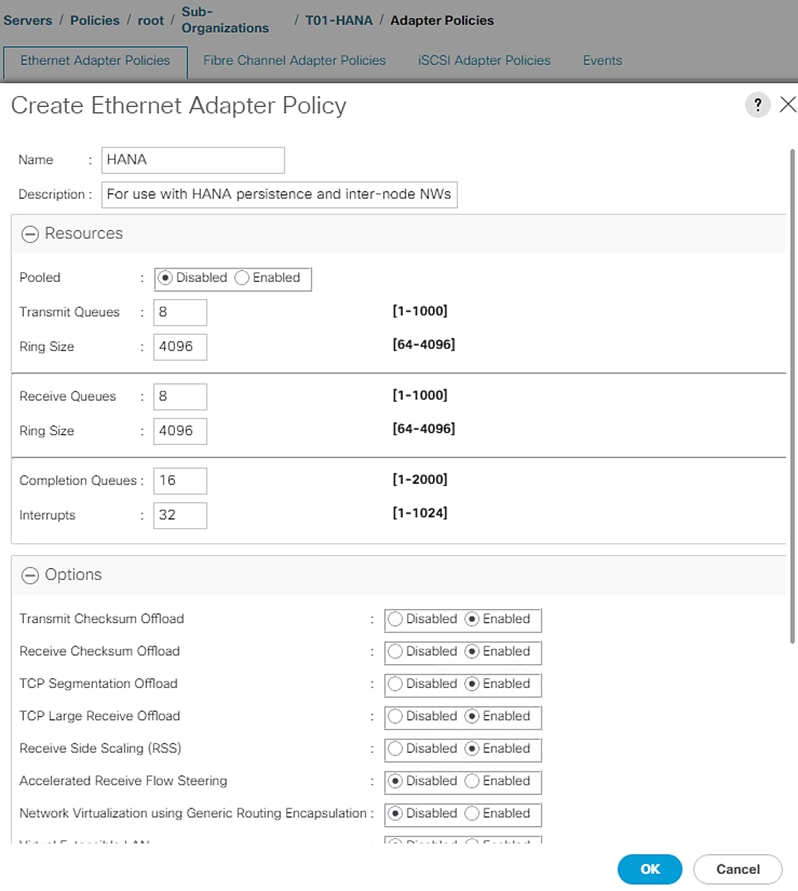
Network Configuration
The core network requirements for SAP HANA are covered by Cisco UCS defaults. Cisco UCS is based on 10/25-GbE and provides redundancy via the Dual Fabric concept. The Service Profile is configured to distribute the traffic across Fabric Interconnect A and B. During normal operation, the inter-node network and /hana/data filesystem access traffic is on FI A and all the other network traffic including /hana/log filesystem access is on FI B. The inter-node traffic flows from a Blade Server to the Fabric Interconnect A and back to another Blade Server. All the other traffic must go over the Cisco Nexus switches to storage or to the data center network. With the integrated algorithms for bandwidth allocation and quality of service the Cisco UCS and Cisco Nexus distributes the traffic in an efficient way.
LAN Tab Configurations
Within Cisco UCS, all the network types for an SAP HANA system are reflected by defined VLANs. Network design from SAP has seven SAP HANA related networks and two infrastructure related networks. The VLAN IDs can be changed if required to match the VLAN IDs in the data center network – for example, ID 224 for backup should match the configured VLAN ID at the data center network switches. Even though nine VLANs are defined, VLANs for all the networks are not necessary if the solution will not use the network. For example, if the Replication Network is not used in the solution, then VLAN ID 225 does not have to be created.
Create VLANs
To configure the necessary VLANs for the Cisco UCS environment, follow these steps:
1. In Cisco UCS Manager, click the LAN tab in the navigation pane.
2. Select LAN > LAN Cloud.
3. Right-click VLANs.
4. Select Create VLANs.
5. Enter hanadata-node as the name of the VLAN to be used for /hana/data/ filesystem network access.
6. Keep the Common/Global option selected for the scope of the VLAN.
7. Enter <,var_hana_data_vlan_ucsnode>>> as the ID of the HANA Data filesystem network of storage network.
8. Keep the Sharing Type as None.
9. Click OK and then click OK again.
10. Repeat steps 1-9 to configure the rest of the VLANs as listed in the table below.
Table 3 VLANs used in this CVD
| VLAN name |
VLAN ID |
Sample VLAN ID used in validation setup |
| <<var_hana_data_vlan_ucsnode>> |
201 |
|
| hanalog-node |
<<var_hana_log_vlan_ucsnode>> |
228 |
| hanashared-node |
<<var_hana_shared_vlan_ucsnode>> |
130 |
| node-admin |
<<var_admin_vlan_ucsnode>> |
76 |
| iscsi-initA |
<<iSCSI_vlan_ucsnode_A>> |
128 |
| iscsi-initB |
<<iSCSI_vlan_ucsnode_B>> |
129 |
| internode |
<<var_internode_vlan_ucs>> |
220 |
| backup |
<<var_backup_vlan_ucsnode>> |
224 |
| appserver |
<<var_appserver_vlan_ucsnode>> |
226 |
| datasource |
<<var_datasource_vlan_ucsnode>> |
225 |
| replication |
<<var_replication_vlan_ucsnode>> |
221 |
Figure 71 VLANs
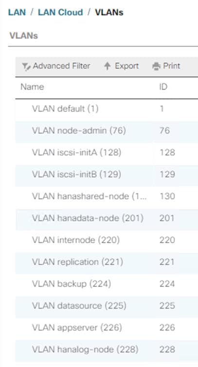
Create VLAN Groups
For easier management and bandwidth segregation on the Fabric Interconnect, VLAN Groups are created within the Cisco UCS. Bundle inter-node, HANA persistence networks and client/sap application server networks in a VLAN group and create a separate VLAN group consisting of iSCSI traffic for booting, HANA nodes admin/ management traffic, backup and system replication networks.
VLAN group with HANA networks is assigned to 160Gbps bandwidth port channels with 4 x 40G ports - port channels 11 and 12 we created earlier on FI-A and FI-B respectively. VLAN group of backup, iSCSI boot, HANA nodes admin and replication networks is assigned to 80Gbps bandwidth capable port channels with 2 x 40G ports, in other words, port channels 21 and 22 on FI-A and FI-B respectively.
To configure the necessary VLAN Groups for the Cisco UCS environment, follow these steps:
1. In Cisco UCS Manager, click the LAN tab in the navigation pane.
2. Select LAN > LAN Cloud.
3. Right-click VLAN Groups.
4. Select Create VLAN Groups.
5. Enter hana-networks-1 as the name of the VLAN Group. Select all the created VLANs as shown below:
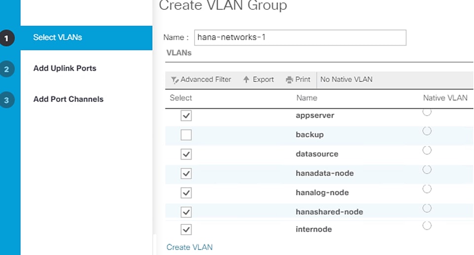
6. Click Next.
7. Click Next on Add Uplink Ports, since you will use port-channel.
8. Choose port-channels created for uplink network. Click >>.
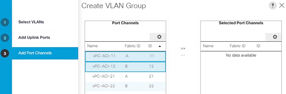
9. Click Finish.
10. Create hana-networks-2 vlan-group including the Backup and System Replication networks.
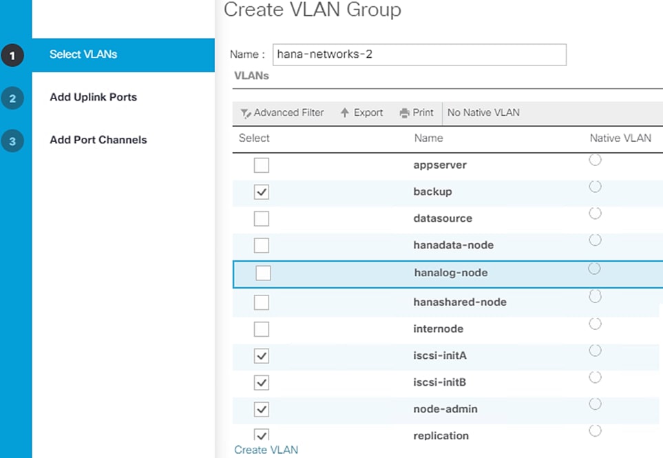
11. Click Next.
12. Click Next on Add Uplink Ports, since you will use port-channel.
13. Choose port-channels created for uplink network. Click >>.
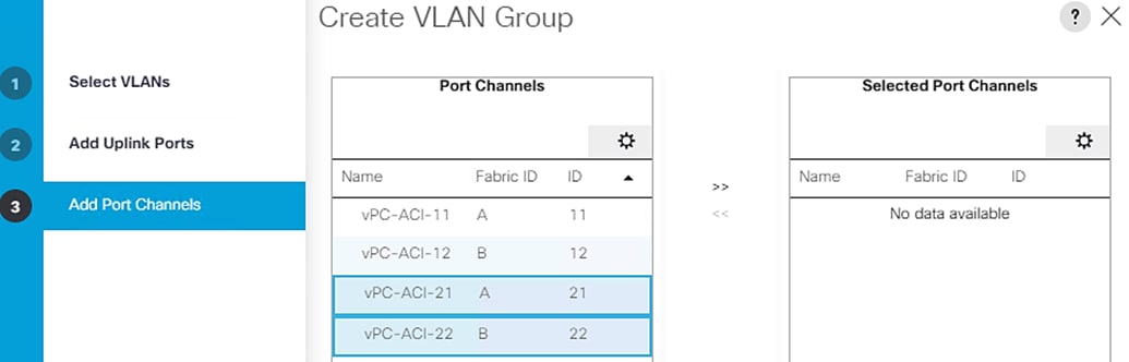
14. Click Finish.
Create vNIC Templates
Each VLAN is mapped to a vNIC template to specify the characteristic of a specific network. The vNIC template configuration settings include MTU size, Failover capabilities and MAC-Address pools.
Create vNIC Template for iSCSI via Fabric A
To create iSCSI virtual network interface card (vNIC) templates for the Cisco UCS environment within the FlexPod Organization, follow these steps:
1. Select LAN.
2. Expand Policies > root > Sub-Organizations > T01-HANA.
3. Right-click vNIC Templates.
4. Select Create vNIC Template.
5. Enter iSCSI-A as the vNIC template name.
6. Select Fabric A. Do not select the Enable Failover checkbox.
7. Leave Redundancy Type set at No Redundancy.
8. Under Target, make sure that only the Adapter checkbox is selected.
9. Select Updating Template for Template Type.
10. Under VLANs, select only iscsi-initA.
11. Select iscsi-initA as the native VLAN.
12. Leave vNIC Name set for the CDN Source.
13. Under MTU, enter 9000.
14. From the MAC Pool list, select T01-pathA.
15. From the Network Control Policy list, select Enable-CDP-LLDP.
![]() For most SAP HANA use cases, the network traffic is well distributed across the two Fabrics (Fabric A and Fabric B) using the default setup. In special cases, it can be required to rebalance this distribution for better overall performance. This can be done in the vNIC template with the Fabric ID setting. Note that the MTU settings must match the configuration in customer data center. MTU setting of 9000 is recommended for best performance.
For most SAP HANA use cases, the network traffic is well distributed across the two Fabrics (Fabric A and Fabric B) using the default setup. In special cases, it can be required to rebalance this distribution for better overall performance. This can be done in the vNIC template with the Fabric ID setting. Note that the MTU settings must match the configuration in customer data center. MTU setting of 9000 is recommended for best performance.
16. Repeat steps1-15 to create vNIC template for each Network Interface.
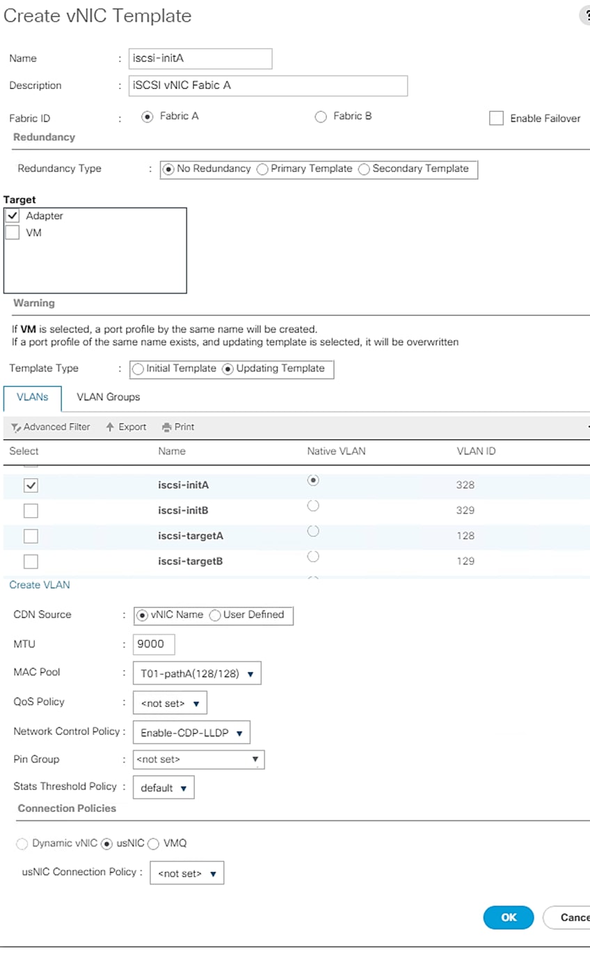
Create vNIC Template for iSCSI with Fabric B
To create a vNIC template for iSCSI with fabric B, follow these steps:
1. Right-click vNIC Templates.
2. Select Create vNIC Template.
3. Enter iscsi-initB as the vNIC template name.
4. Select Fabric B. Do not select the Enable Failover checkbox.
5. Leave Redundancy Type set at No Redundancy.
6. Under Target, make sure that only the Adapter checkbox is selected.
7. Select Updating Template for Template Type.
8. Under VLANs, select only iscsi-initB.
9. Select iscsi-initB as the native VLAN.
10. Leave vNIC Name set for the CDN Source.
11. Under MTU, enter 9000.
12. From the MAC Pool list, select T01-pathB.
13. From the Network Control Policy list, select Enable-CDP-LLDP.
14. Click OK to complete creating the vNIC template.
15. Click OK.
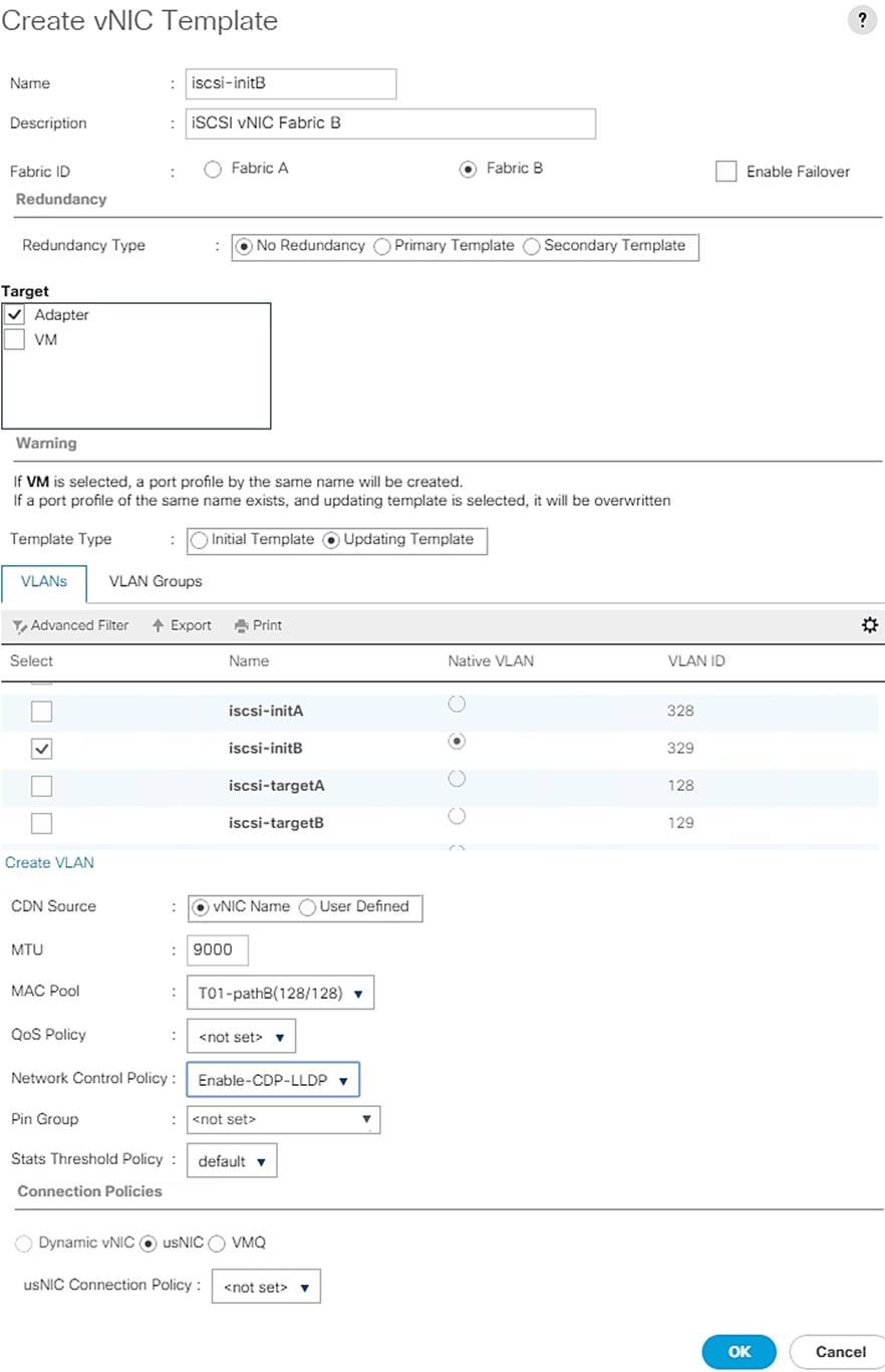
Create a vNIC Template for Inter-node Network
To create a vNIC template for Inter-node network, follow these steps:
1. In Cisco UCS Manager, click the LAN tab in the navigation pane.
2. Choose Policies > root > Sub-Organization > T01-HANA.
3. Right-click vNIC Templates.
4. Choose Create vNIC Template.
5. Enter internode as the vNIC template name.
6. Keep Fabric B selected.
7. Check the Enable Failover checkbox.
8. Under Target, make sure that the VM checkbox is unchecked.
9. Choose Updating Template as the Template Type.
10. Under VLANs, check the checkboxes for internode.
11. Set internode as the native VLAN.
12. For MTU, enter 9000.
13. In the MAC Pool list, choose T01-pathB.
14. For Network Control Policy, choose default from drop-down list.
15. Click OK to create the vNIC template.
Create a vNIC Template for HANA Data Network
To create a vNIC template for HANA Data filesystem network, follow these steps:
1. In Cisco UCS Manager, click the LAN tab in the navigation pane.
2. Choose Policies > root > Sub-Organization > T01-HANA.
3. Right-click vNIC Templates.
4. Choose Create vNIC Template.
5. Enter hanadata as the vNIC template name.
6. Keep Fabric A selected.
7. Check the Enable Failover checkbox.
8. Under Target, make sure that the VM checkbox is unchecked.
9. Choose Updating Template as the Template Type.
10. Under VLANs, check the checkboxes for hanadata-node.
11. Set hanadata-node as the native VLAN.
12. For MTU, enter 9000.
13. In the MAC Pool list, choose T01-pathA.
14. For Network Control Policy, choose Enable-CDP-LLDP from drop-down list
15. Click OK to create the vNIC template.
Create a vNIC Template for HANA Log Network
To create a vNIC template for a HANA Log filesystem network, follow these steps:
1. In Cisco UCS Manager, click the LAN tab in the navigation pane.
2. Choose Policies > root > Sub-Organization > T01-HANA.
3. Right-click vNIC Templates.
4. Choose Create vNIC Template.
5. Enter hanalog as the vNIC template name.
6. Keep Fabric A selected.
7. Check the Enable Failover checkbox.
8. Under Target, make sure that the VM checkbox is unchecked.
9. Choose Updating Template as the Template Type.
10. Under VLANs, check the checkboxes for hanalog-node.
11. Set hanalog-node as the native VLAN.
12. For MTU, enter 9000.
13. In the MAC Pool list, choose T01-pathA.
14. For Network Control Policy, choose Enable-CDP-LLDP from drop-down list.
15. Click OK to create the vNIC template.
Create a vNIC Template for HANA shared Network
To create a vNIC template for an application network, follow these steps:
1. In Cisco UCS Manager, click the LAN tab in the navigation pane.
2. Choose Policies > root > Sub-Organization > T01-HANA.
3. Right-click vNIC Templates.
4. Choose Create vNIC Template.
5. Enter hanashared as the vNIC template name.
6. Keep Fabric A selected.
7. Check the Enable Failover checkbox.
8. Under Target, make sure that the VM checkbox is unchecked.
9. Choose Updating Template as the Template Type.
10. Under VLANs, check the checkboxes for hanashared-node.
11. Set hanashared-node as the native VLAN.
12. For MTU, enter 9000.
13. In the MAC Pool list, choose T01-pathA.
14. For Network Control Policy, choose Enable-CDP=LLDP from drop-down list.
15. Click OK to create the vNIC template.
Create a vNIC Template for Application Server Network
To create vNIC template for Application Server network, follow these steps:
1. In Cisco UCS Manager, click the LAN tab in the navigation pane.
2. Choose Policies > root > Sub-Organization > T01-HANA.
3. Right-click vNIC Templates.
4. Choose Create vNIC Template.
5. Enter appserver as the vNIC template name.
6. Keep Fabric B selected.
7. Check the Enable Failover checkbox.
8. Under Target, make sure that the VM checkbox is unchecked.
9. Choose Updating Template as the Template Type.
10. Under VLANs, check the checkboxes for appserver.
11. Set appserver as the native VLAN.
12. For MTU, enter 9000.
13. In the MAC Pool list, choose HANA-Fab-A.
14. For Network Control Policy, choose default from drop-down list.
15. Click OK to create the vNIC template.
Create a vNIC Template for Data Source Network
To create vNIC template for Data Source network, follow these steps:
1. In Cisco UCS Manager, click the LAN tab in the navigation pane.
2. Choose Policies > root > Sub-Organization > T01-HANA.
3. Right-click vNIC Templates.
4. Choose Create vNIC Template.
5. Enter datasource as the vNIC template name.
6. Keep Fabric B selected.
7. Check the Enable Failover checkbox.
8. Under Target, make sure that the VM checkbox is unchecked.
9. Choose Updating Template as the Template Type.
10. Under VLANs, check the checkboxes for datasource.
11. Set datasource as the native VLAN.
12. For MTU, enter 9000.
13. In the MAC Pool list, choose HANA-Fab-A.
14. For Network Control Policy, choose default from drop-down list.
15. Click OK to create the vNIC template.
Create a vNIC Template for Backup Network
To create vNIC template for a backup network, follow these steps:
1. In Cisco UCS Manager, click the LAN tab in the navigation pane.
2. Choose Policies > root > Sub-Organization > T01-HANA.
3. Right-click vNIC Templates
4. Choose Create vNIC Template.
5. Enter backup as the vNIC template name.
6. Keep Fabric B selected.
7. Check the Enable Failover checkbox.
8. Under Target, make sure that the VM checkbox is unchecked.
9. Choose Updating Template as the Template Type.
10. Under VLANs, check the checkboxes for backup.
11. Set backup as the native VLAN.
12. For MTU, enter 9000.
13. In the MAC Pool list, choose T01-pathB.
14. For Network Control Policy, choose Enable-CDP-LLDP from drop-down list.
15. Click OK to create the vNIC template.
Create a vNIC Template for System Replication Network
To create a vNIC template for a system replication network, follow these steps:
1. In Cisco UCS Manager, click the LAN tab in the navigation pane.
2. Choose Policies > root > Sub-Organization > T01-HANA.
3. Right-click vNIC Templates
4. Choose Create vNIC Template.
5. Enter replication as the vNIC template name.
6. Keep Fabric A selected.
7. Check the Enable Failover checkbox.
8. Under Target, make sure that the VM checkbox is unchecked.
9. Choose Updating Template as the Template Type.
10. Under VLANs, check the checkboxes for replication.
11. Set replication as the native VLAN.
12. For MTU, enter 9000.
13. In the MAC Pool list, choose T01-pathA.
14. For Network Control Policy, choose default from drop-down list.
15. Click OK to create the vNIC template.
Create a vNIC Template for Management Network
To create a vNIC template for a management network, follow these steps:
1. In Cisco UCS Manager, click the LAN tab in the navigation pane.
2. Choose Policies > root > Sub-Organization > T01-HANA.
3. Right-click vNIC Templates.
4. Choose Create vNIC Template.
5. Enter admin as the vNIC template name.
6. Keep Fabric A selected.
7. Check the Enable Failover checkbox.
8. Under Target, make sure that the VM checkbox is unchecked.
9. Choose Updating Template as the Template Type.
10. Under VLANs, check the checkboxes for node-admin.
11. Set node-admin as the native VLAN.
12. For MTU, enter 1500.
13. In the MAC Pool list, choose T01-pathA.
14. For Network Control Policy, choose default from drop-down list.
15. Click OK to create the vNIC template.
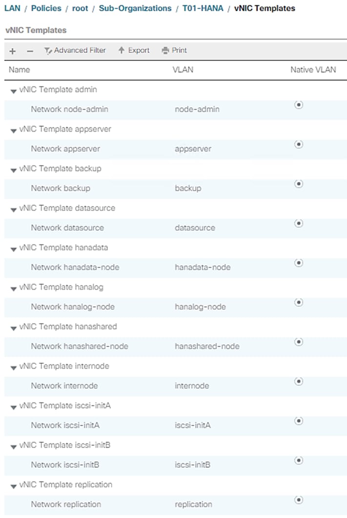
Create vNIC/vHBA Placement Policy
Cisco UCS assigns virtual network interface connections (vCons) to the PCIe adapter cards in the server. Each vCon is a virtual representation of a physical adapter that can be assigned vNICs and vHBAs.
For blade or rack servers that contain one adapter, Cisco UCS assigns all vCons to that adapter.
For blade or rack servers that contain two or three adapters, Cisco UCS assigns the vCons based on the selected virtual slot mapping scheme. This can be one of the following:
· Round Robin— In a server with two adapter cards, Cisco UCS assigns vCon1 and vCon3 to Adapter1, then assigns vCon2 and vCon4 to Adapter2. In a server with three adapter cards, Cisco UCS assigns vCon1 to Adapter1, vCon2 and vCon4 to Adapter2, and vCon3 to Adapter3. This is the default scheme.
· Linear Ordered— In a server with two adapter cards, Cisco UCS assigns vCon1 and vCon2 to Adapter1, then assigns vCon3 and vCon4 to Adapter2.In a server with three adapter cards, Cisco UCS assigns vCon1 to Adapter1 and vCon2 to Adapter2, then assigns vCon3 and vCon4 to Adapter3.
To create a vNIC/vHBA placement policy for the SAP HANA hosts, follow these steps:
1. Find the installed adapters in the system:
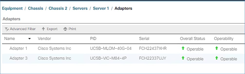
2. Choose a virtual slot mapping scheme and create a placement policy.
3. In Cisco UCS Manager, click the Servers tab in the navigation pane.
4. Select Policies > root > Sub-Organization > HANA.
5. Right-click vNIC/vHBA Placement Policies.
6. Select Create Placement Policy.
7. Enter HANA as the name of the placement policy and select Liner Ordered for Virtual Slot Mapping Scheme.
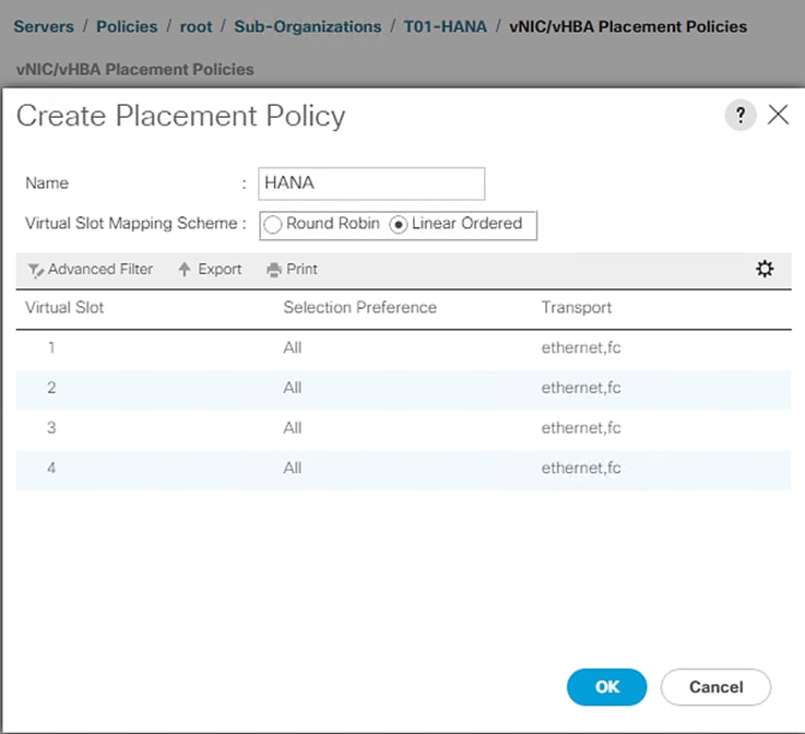
For the Placement policy, considering the installed adapters helps to be sure of what vCONs to use for vNIC assignment.
In the validation setup, Cisco UCS B480 M5 server configured with VIC1440 and VIC1480 is used. These appear as Adpater1 and Adapter 3. Linear ordered virtual slot mapping scheme based placement policy with two adapters suggests that we should be using the vCONs 1 and 3 for vNIC assignment.
Create LAN Connectivity Policy
With LAN connectivity policy, you need to define the vNICs that a system needs to have in order to cater to the specific networks the use-case demands.
For both SAP HANA scale up and scale out system use-cases, apart from the admin/management the node may need backup and application server network connections, at a minimum. It could have other networks depending on the usage.
However, for the scale out system scenario, inter-node communication is mandatory and that is what distinguishes it from a single host system’s policy.
In the following steps, you will create separate LAN connectivity policies for the two standard use-cases. This further simplifies the service profile template creation by having the pre-determined vNICs already part of the network configuration.
Single-Host Systems Use-Case (SAP HANA Scale-Up system)
To configure the necessary LAN Connectivity Policy within theT01-HANA Organization, follow these steps:
1. In Cisco UCS Manager, click LAN.
2. Expand LAN > Policies > root > Sub-Organizations > T01-HANA.
3. Right-click LAN Connectivity Policies.
4. Select Create LAN Connectivity Policy.
5. Enter single-host as the name of the policy.
6. Click Add to add a vNIC.
7. In the Create vNIC dialog box, enter admin as the name of the vNIC.
8. Select the Use vNIC Template checkbox.
9. In the vNIC Template list, select admin.
10. In the Adapter Policy list, select Linux.
11. Click OK to add this vNIC to the policy.
12. Click Add to add another vNIC to the policy.
13. In the Create vNIC box, enter hana-data as the name of the vNIC.
14. Select the Use vNIC Template checkbox.
15. In the vNIC Template list, select hanadata.
16. In the Adapter Policy list, select HANA.
17. Click OK to add the vNIC to the policy.
18. Click Add to add another vNIC to the policy.
19. In the Create vNIC dialog box, enter hana-log as the name of the vNIC.
20. Select the Use vNIC Template checkbox.
21. In the vNIC Template list, select hanalog.
22. In the Adapter Policy list, select HANA.
23. Click OK to add this vNIC to the policy.
24. Click Add to add another vNIC to the policy.
25. In the Create vNIC dialog box, enter hana-shared as the name of the vNIC.
26. Select the Use vNIC Template checkbox.
27. In the vNIC Template list, select hanashared.
28. In the Adapter Policy list, select HANA.
29. Click OK to add this vNIC to the policy.
30. Click Add to add a vNIC.
31. In the Create vNIC dialog box, enter app-connect as the name of the vNIC.
32. Select the Use vNIC Template checkbox.
33. In the vNIC Template list, select appserver.
34. In the Adapter Policy list, select Linux.
35. Click OK to add this vNIC to the policy.
36. Click Add to add a vNIC.
37. In the Create vNIC dialog box, enter backup as the name of the vNIC.
38. Select the Use vNIC Template checkbox.
39. In the vNIC Template list, select backup.
40. In the Adapter Policy list, select Linux.
41. Click OK to add this vNIC to the policy.
42. Click Add to add a vNIC.
43. In the Create vNIC dialog box, enter iscsi-a as the name of the vNIC.
44. Select the Use vNIC Template checkbox.
45. In the vNIC Template list, select iscsi-initA.
46. In the Adapter Policy list, select Linux.
47. Click OK to add this vNIC to the policy.
48. Click Add to add a vNIC to the policy.
49. In the Create vNIC dialog box, enter iscsi-b as the name of the vNIC.
50. Select the Use vNIC Template checkbox.
51. In the vNIC Template list, select iscsi-initB.
52. In the Adapter Policy list, select Linux.
53. Click OK to add this vNIC to the policy.
54. Expand Add iSCSI vNICs.
55. Select Add in the Add iSCSI vNICs section.
56. Set the name to iscsi-boot-a.
57. Select iscsi-a as the Overlay vNIC.
58. Set the iSCSI Adapter Policy to default.
59. Leave the VLAN set to iscsi-initA (native).
60. Leave the MAC Address set to None.
61. Click OK.
62. Select Add in the Add iSCSI vNICs section.
63. Set the name to iscsi-boot-b.
64. Select iscsi-b as the Overlay vNIC.
65. Set the iSCSI Adapter Policy to default.
66. Leave the VLAN set to iscsi-initB (native).
67. Leave the MAC Address set to None.
68. Click OK.
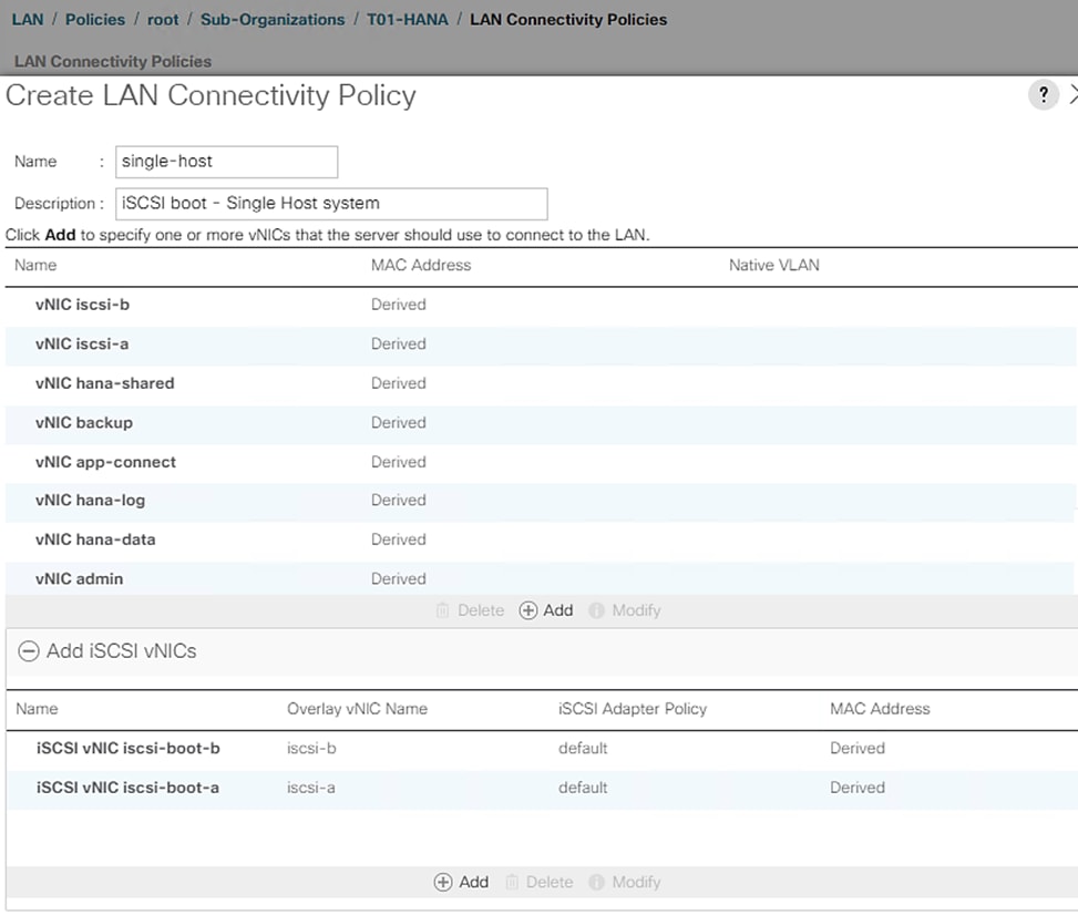
Multi-host Systems Use-Case [SAP HANA Scale-Out system]
To configure the necessary LAN Connectivity Policy within the T01-HANA Organization, follow these steps:
1. In Cisco UCS Manager, click LAN.
2. Expand LAN > Policies > root > Sub-Organizations > T01-HANA Organization.
3. Right-click LAN Connectivity Policies.
4. Select Create LAN Connectivity Policy.
5. Enter mutli-host as the name of the policy.
6. Click Add to add a vNIC.
7. In the Create vNIC dialog box, enter admin as the name of the vNIC.
8. Select the Use vNIC Template checkbox.
9. In the vNIC Template list, select admin.
10. In the Adapter Policy list, select Linux.
11. Click OK to add this vNIC to the policy.
12. Click Add to add another vNIC to the policy.
13. In the Create vNIC box, enter hana-data as the name of the vNIC.
14. Select the Use vNIC Template checkbox.
15. In the vNIC Template list, select hanadata.
16. In the Adapter Policy list, select HANA.
17. Click OK to add the vNIC to the policy.
18. Click Add to add a vNIC.
19. In the Create vNIC dialog box, enter hana-log as the name of the vNIC.
20. Select the Use vNIC Template checkbox.
21. In the vNIC Template list, select hanalog.
22. In the Adapter Policy list, select HANA.
23. Click OK to add this vNIC to the policy.
24. Click Add to add a vNIC.
25. In the Create vNIC dialog box, enter hana-shared as the name of the vNIC.
26. Select the Use vNIC Template checkbox.
27. In the vNIC Template list, select hanashared.
28. In the Adapter Policy list, select HANA.
29. Click OK to add this vNIC to the policy.
30. Click Add to add a vNIC.
31. In the Create vNIC dialog box, enter app-connect as the name of the vNIC.
32. Select the Use vNIC Template checkbox.
33. In the vNIC Template list, select appserver.
34. In the Adapter Policy list, select Linux.
35. Click OK to add this vNIC to the policy.
36. Click Add to add a vNIC.
37. In the Create vNIC dialog box, enter backup as the name of the vNIC.
38. Select the Use vNIC Template checkbox.
39. In the vNIC Template list, select backup.
40. In the Adapter Policy list, select Linux.
41. Click OK to add this vNIC to the policy.
42. Click Add to add a vNIC.
43. In the Create vNIC dialog box, enter inter-node as the name of the vNIC.
44. Select the Use vNIC Template checkbox.
45. In the vNIC Template list, select internode.
46. In the Adapter Policy list, select HANA.
47. Click OK to add this vNIC to the policy.
48. Click Add to add a vNIC.
49. In the Create vNIC dialog box, enter iscsi-a as the name of the vNIC.
50. Select the Use vNIC Template checkbox.
51. In the vNIC Template list, select iscsi-initA.
52. In the Adapter Policy list, select Linux.
53. Click OK to add this vNIC to the policy.
54. Click Add to add a vNIC to the policy.
55. In the Create vNIC dialog box, enter iscsi-b as the name of the vNIC.
56. Select the Use vNIC Template checkbox.
57. In the vNIC Template list, select iscsi-initB.
58. In the Adapter Policy list, select Linux.
59. Click OK to add this vNIC to the policy.
60. Expand Add iSCSI vNICs.
61. Select Add in the Add iSCSI vNICs section.
62. Set the name to iscsi-boot-a.
63. Select iscsi-a as the Overlay vNIC.
64. Set the iSCSI Adapter Policy to default.
65. Leave the VLAN set to iscsi-initA (native).
66. Leave the MAC Address set to None.
67. Click OK.
68. Select Add in the Add iSCSI vNICs section.
69. Set the name to iscsi-boot-b.
70. Select iscsi-b as the Overlay vNIC.
71. Set the iSCSI Adapter Policy to default.
72. Leave the VLAN set to iscsi-initB (native).
73. Leave the MAC Address set to None.
74. Click OK.
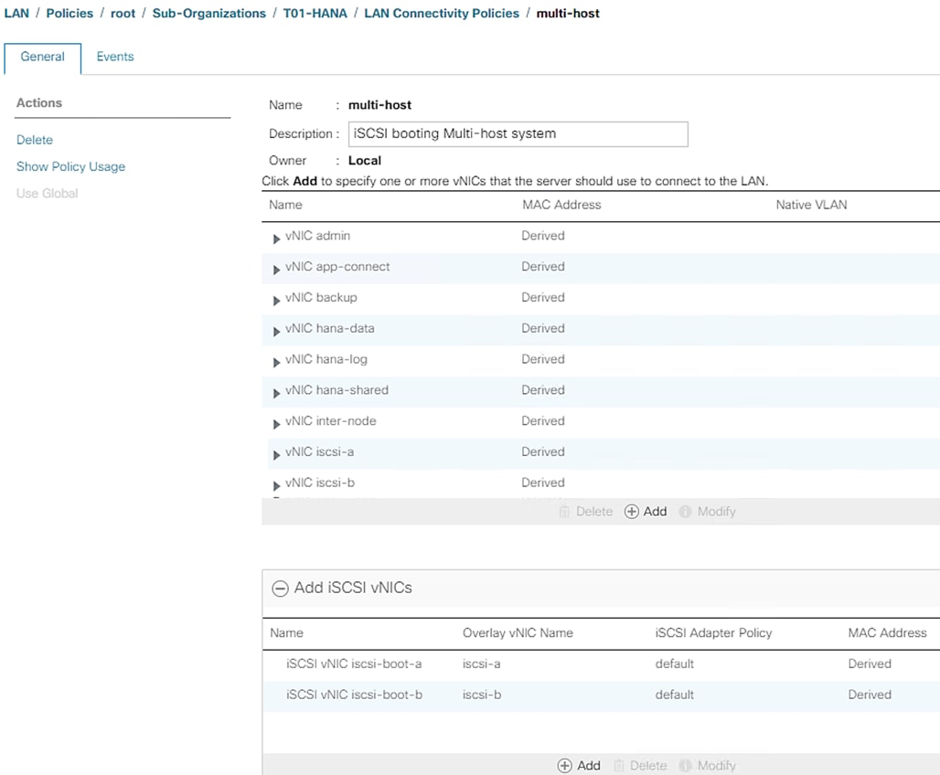
Create iSCSI Boot Policy
This procedure applies to a Cisco UCS environment in which two iSCSI logical interfaces (LIFs) are on cluster node 1 (iscsi_lif_1a and iscsi_lif_1b) and two iSCSI LIFs are on cluster node 2 (iscsi_lif_2a and iscsi_lif_2b).
![]() One boot policy is configured in this procedure. The policy configures the primary target to be iscsi_lif_1a.
One boot policy is configured in this procedure. The policy configures the primary target to be iscsi_lif_1a.
To create a boot policy for the Cisco UCS environment within the T01-HANA Organization, follow these steps:
1. In Cisco UCS Manager, click Servers.
2. Expand Policies > root > Sub-Organizations > T01-HANA Organization.
3. Right-click Boot Policies.
4. Select Create Boot Policy.
5. Enter iscsi-boot-hana as the name of the boot policy.
6. Optional: Enter a description for the boot policy.
7. Do not select the Reboot on Boot Order Change checkbox.
8. Leave Enforce on vNIC/vHBA/iSCSI Name checkbox selected.
9. Select the Legacy Mode.
10. Expand the Local Devices drop-down list and select Add CD/DVD. Collapse Local Devices.
11. Expand the iSCSI vNICs drop-down list and select Add iSCSI Boot.
12. In the Add iSCSI Boot dialog box, enter iscsi-boot-a. This is the Fabric A’s iSCSI vNIC we created in the previous section.
13. Click OK.
14. Select Add iSCSI Boot.
15. In the Add iSCSI Boot dialog box, enter iscsi-boot-b. This is the Fabric B’s iSCSI vNIC we created in the previous section.
16. Click OK.
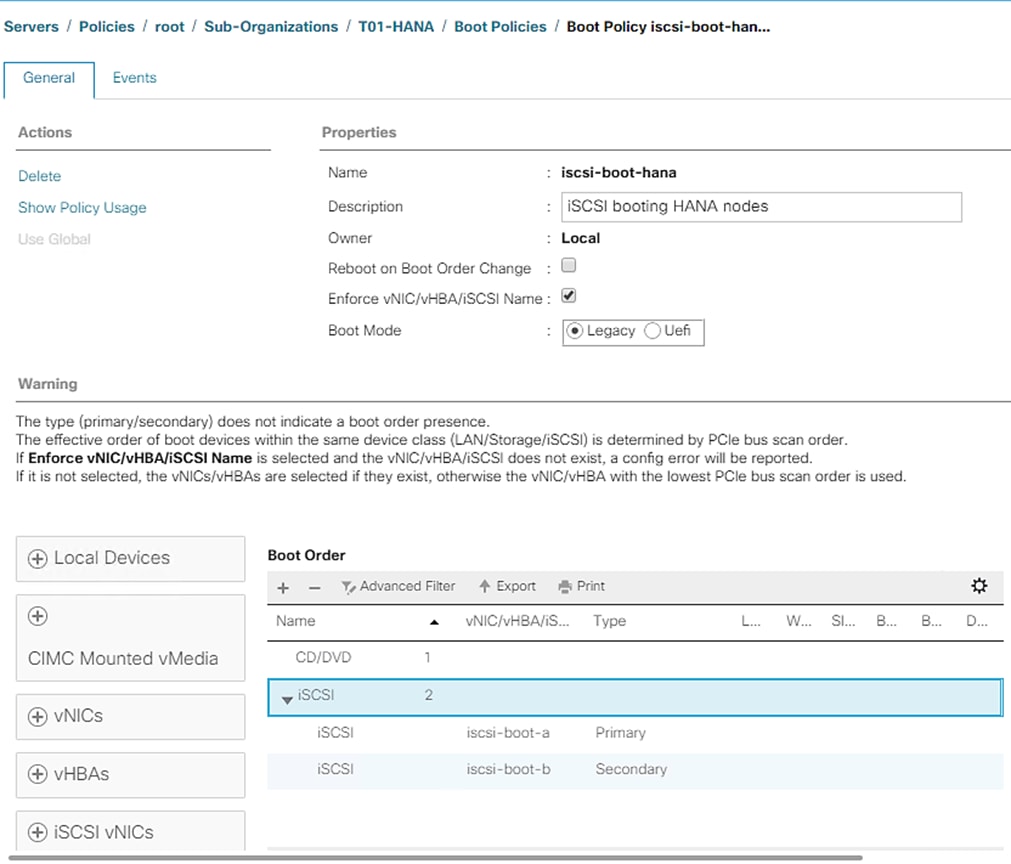
17. Click OK then click OK again to create the policy.
Create Service Profile Template for SAP HANA Node
This section details the service profile template creation procedure. The steps to create service profile template to instantiate HANA nodes for [SAP HANA scale up or scale out use-case depends on the LAN connectivity policy you select and corresponding placement of vNICs per vCONs.
To create the service profile template, follow these steps:
1. In Cisco UCS Manager, click Servers.
2. Expand Service Profile Templates > root > Sub-Organizations > T01-HANA Organization.
3. Right-click the T01-HANA Organization.
4. Select Create Service Profile Template to open the Create Service Profile Template wizard.
5. Enter HANA-node as the name of the service profile template.
6. Select the “Updating Template” option.
7. Under UUID Assignment, select T01-UUID.
8. Click Next.
Configure Storage Provisioning
To configure the storage provisioning, follow these steps:
1. If you have servers with no physical disks, click on the Local Disk Configuration Policy tab select the default Local Storage Policy. Else, select No-local.
2. Click Next.
Configure Networking Options
To configure the network options for HANA node intended to be scale-up system, follow these steps:
1. Keep the default setting for Dynamic vNIC Connection Policy.
2. Select the “Use Connectivity Policy” option to configure the LAN connectivity.
3. Select single-host from the LAN Connectivity Policy drop-down list.
4. Select IQN-HANA in Initiator Name Assignment.
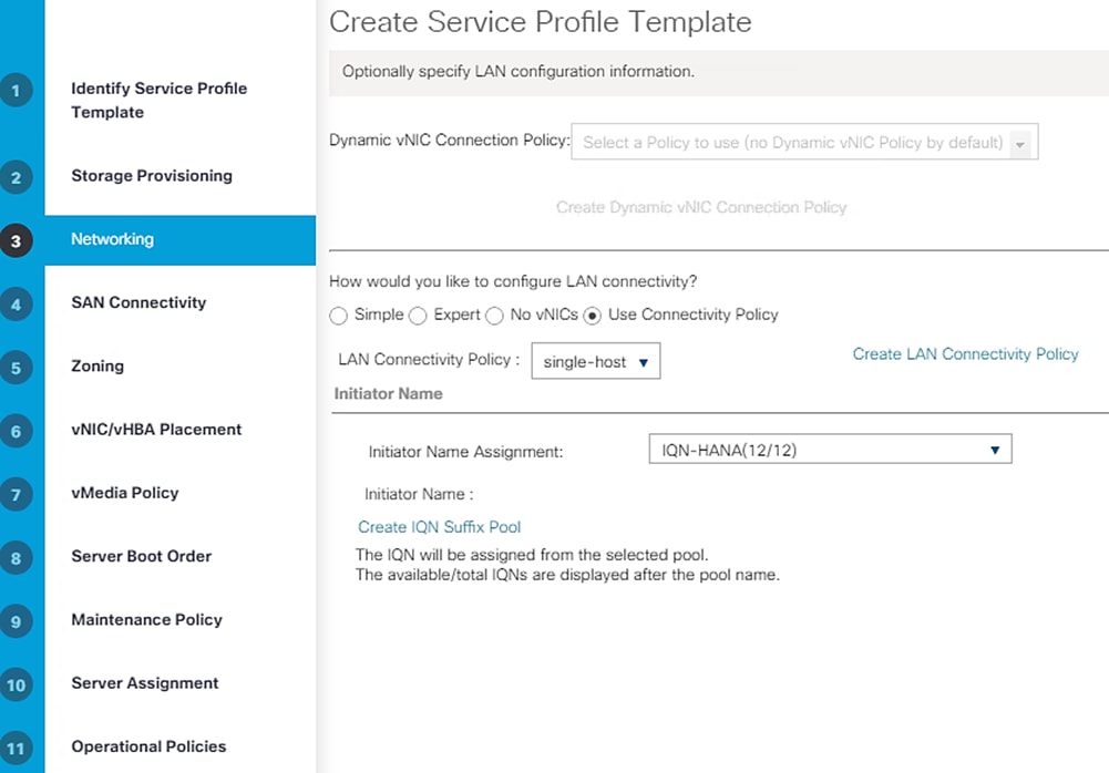
5. Click Next.
OR
To configure the network options for HANA node intended to be part of scale out cluster, follow these steps:
1. Keep the default setting for Dynamic vNIC Connection Policy.
2. Select the “Use Connectivity Policy” option to configure the LAN connectivity.
3. Select multi-host from the LAN Connectivity Policy drop-down list.
4. Select IQN-HANA in Initiator Name Assignment.
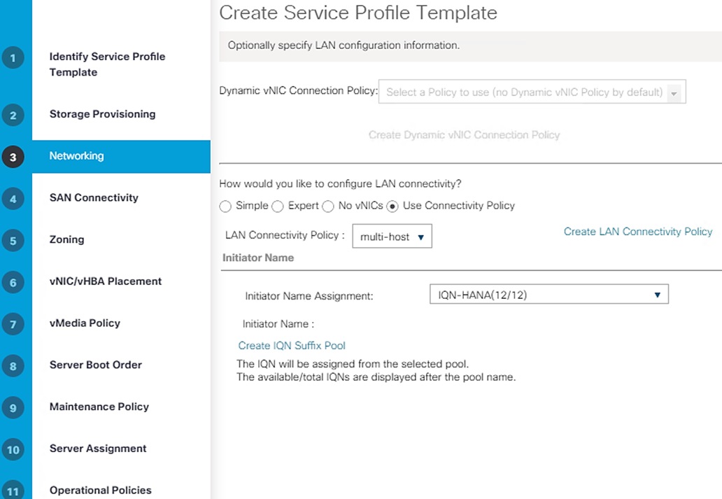
5. Click Next.
Configure Storage Options
To configure the storage options, follow these steps:
1. Select No vHBAs for the “How would you like to configure SAN connectivity?” field.
2. Click Next.
Configure Zoning Options
To configure the zoning options, follow this step:
1. Make no changes and click Next.
Configure vNIC/HBA Placement
To configure the vNIC/HBA placement in case of Single system, follow these steps:
1. In the “Select Placement” list, Select HANA.
2. Assign the vNICs to vCon1 and vCon3 as below:
![]() Even though eight networks were defined, they are optional and if they are not needed in your deployment, the addition of a vNIC template for that network may be omitted.
Even though eight networks were defined, they are optional and if they are not needed in your deployment, the addition of a vNIC template for that network may be omitted.
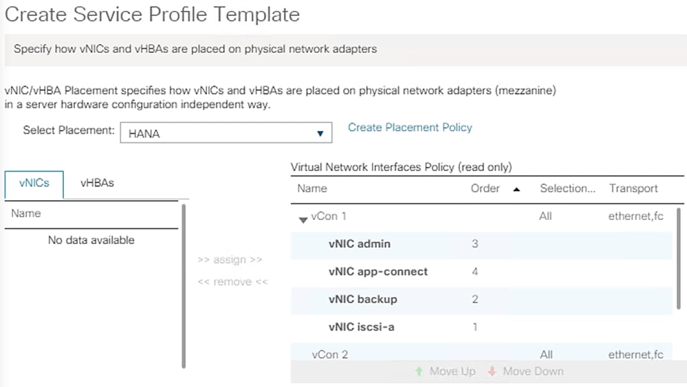
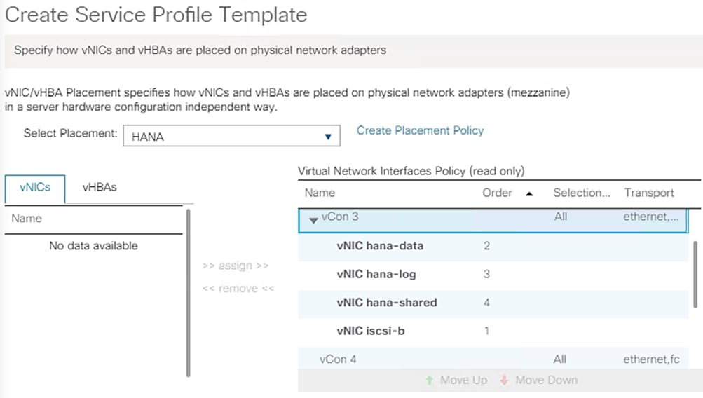
3. Click Next.
To configure the vNIC/HBA placement in case of scale out system, follow these steps:
1. In the “Select Placement” list, Select HANA.
2. Assign the vNICs to vCon1 and vCon3 as below:
![]() Even though eight networks were defined, they are optional and if they are not needed in your deployment, the addition of a vNIC template for that network may be omitted.
Even though eight networks were defined, they are optional and if they are not needed in your deployment, the addition of a vNIC template for that network may be omitted.
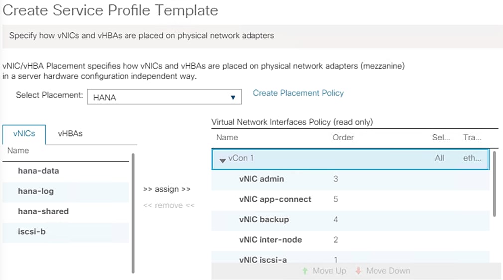
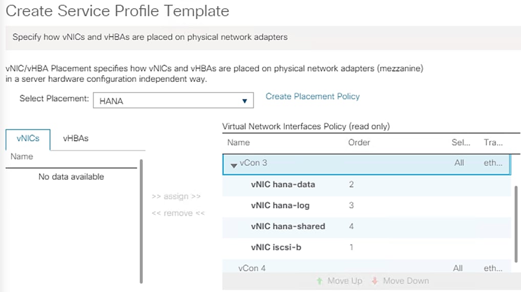
3. Click Next.
Configure vMedia Policy
To configure the vMedia policy, follow these steps:
1. Do not select a vMedia Policy.
2. Click Next.
Configure Server Boot Order
To configure the server boot orders, follow these steps:
1. Select iscsi-boot-hana for Boot Policy.
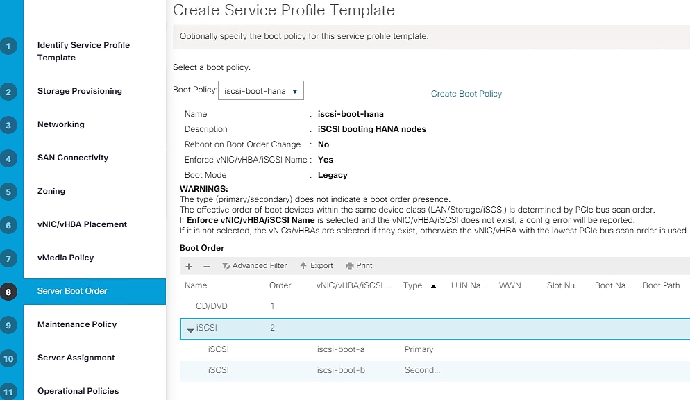
2. In the Boor order, select iscsi-boot-a.
3. Click Set iSCSI Boot Parameters.
4. In the Set iSCSI Boot Parameters pop-up, leave Authentication Profile to <not set> unless you have in-dependently created one appropriate to your environment.
5. Leave the “Initiator Name Assignment” dialog box <not set> to use the single Service Profile Initiator Name defined in the previous steps.
6. The planned logical interfaces [LIFs] definition on NetApp array will have to be kept in mind while assigning the iSCSI target IP addresses. In the validation setup, IP address 192.168.128.21 and 192.168.129.21 are defined on NetApp controller A and 192.168.128.22 and 192.168.129.22 on array controller B.
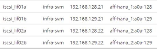
7. Set iSCSI-IP-Pool-A as the “Initiator IP address Policy.”
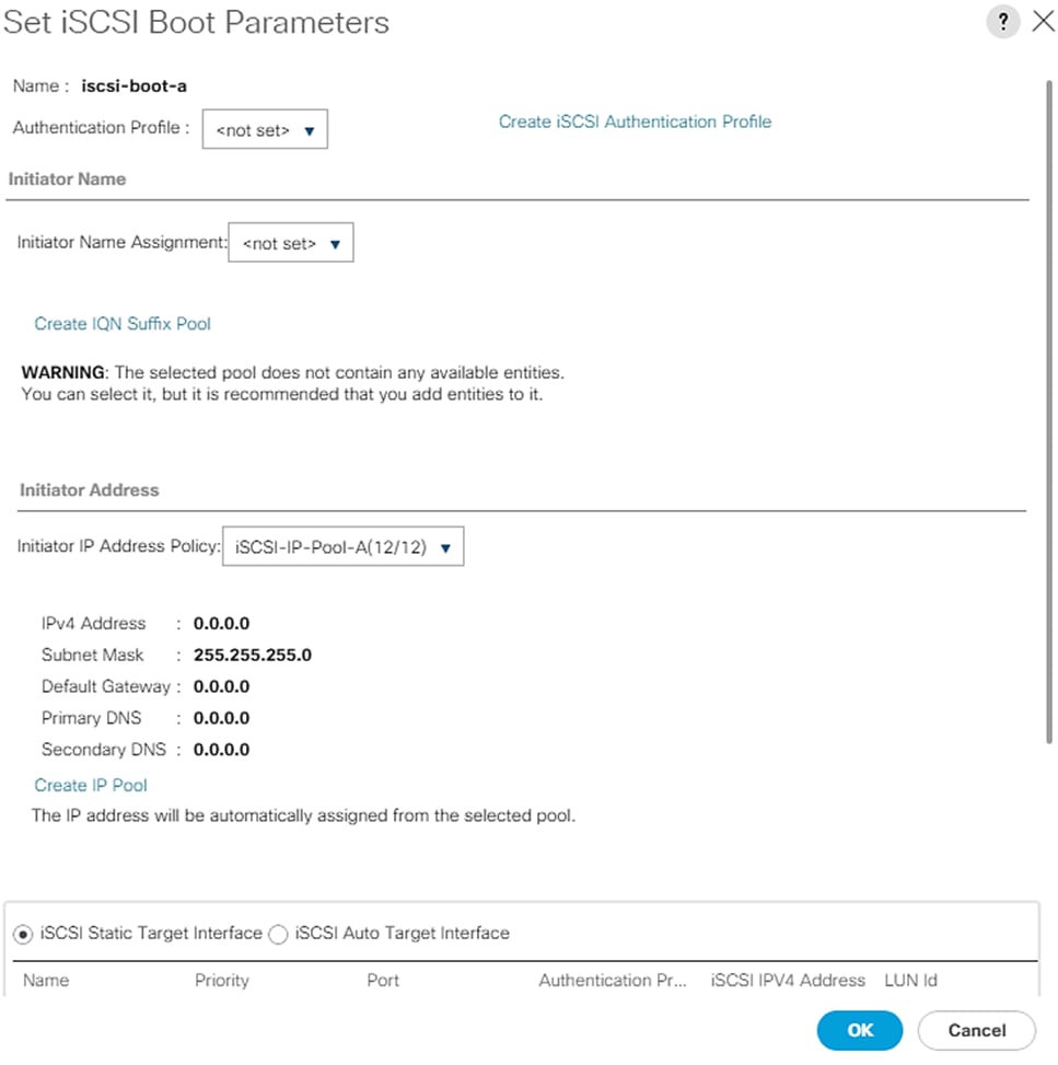
8. Scroll down on the “Set iSCSI Boot Parameters’ page. Select iSCSI Static Target Interface option.
9. Click Add.
10. Enter the iSCSI Target Name.
11. To get the iSCSI target name of Infra-SVM, log into the storage cluster management interface and run the “iscsi show” command”.
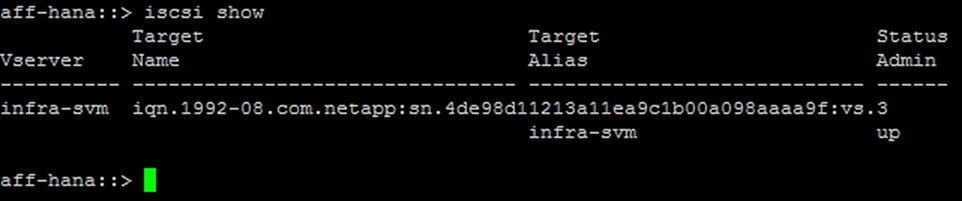
12. Enter the IP address of iscsi_lif_1a for the IPv4 Address field.
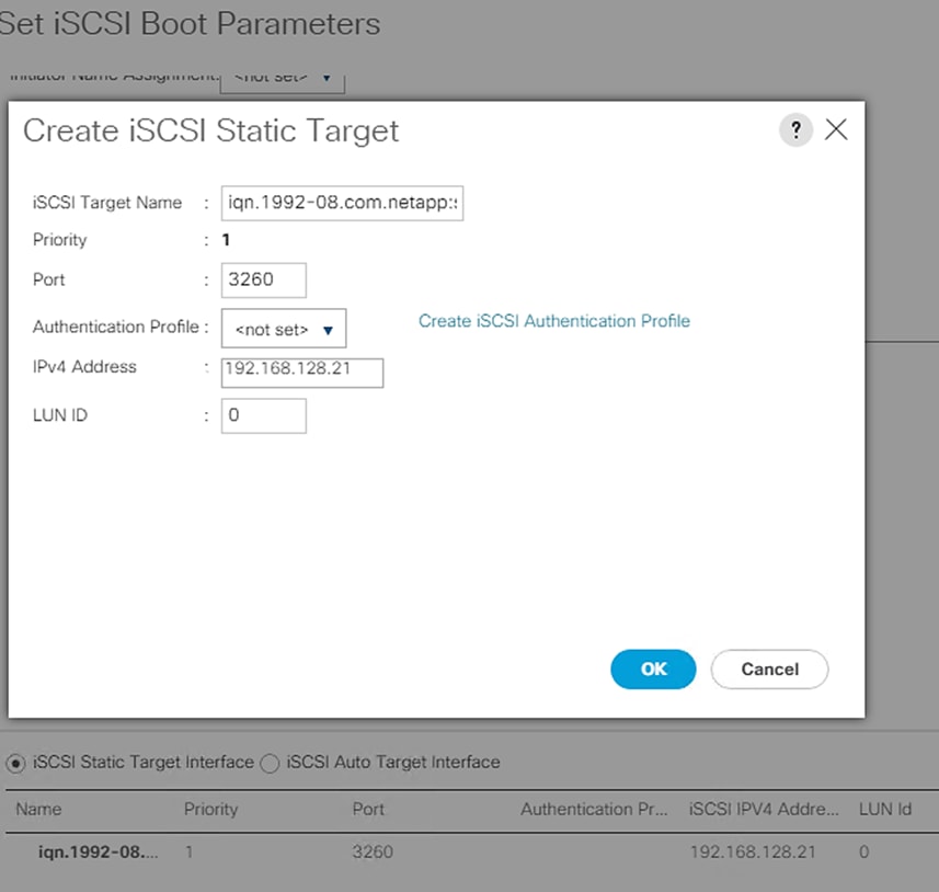
13. Click OK to add the iSCSI static target.
14. Click Add.
15. Enter the iSCSI Target Name.
16. Enter the IP address of iscsi_lif_2a for the IPv4 Address field.
17. Click OK to add the iSCSI static target.
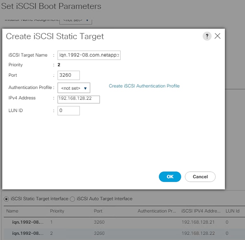
18. Click OK to complete setting the iSCSI Boot Parameters.
19. In the Boot order, select iscsi-boot-b.
20. Click Set iSCSI Boot Parameters.
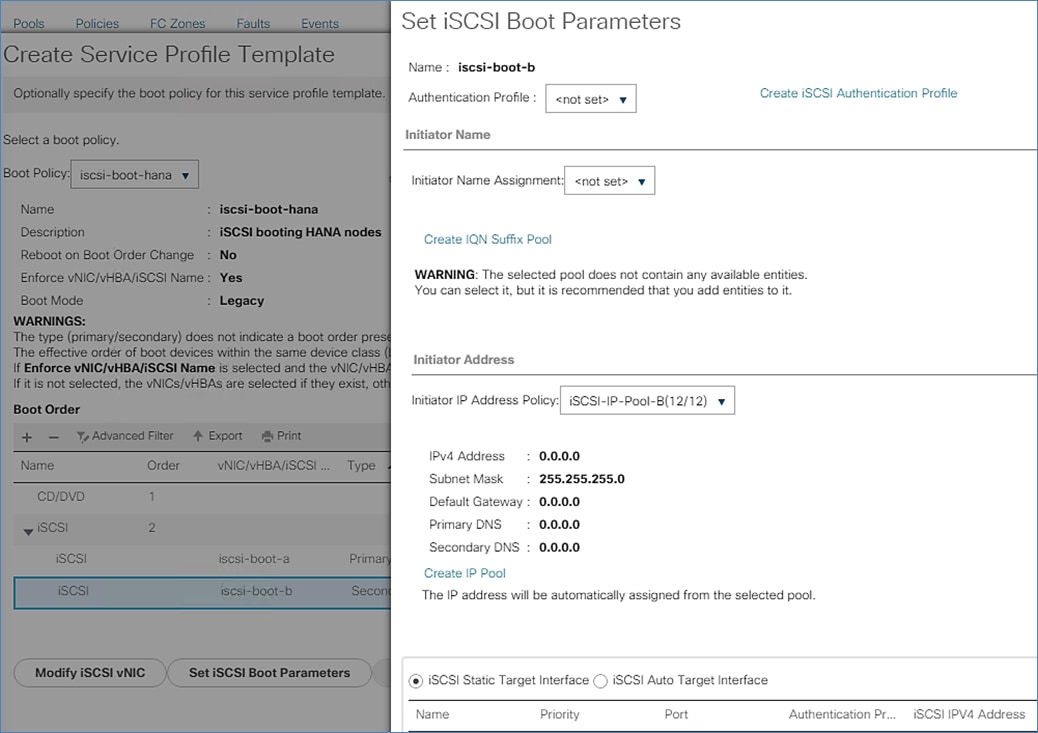
21. In the Set iSCSI Boot Parameters pop-up, leave Authentication Profile to <not set> unless you have in-dependently created one appropriate to your environment.
22. Leave the “Initiator Name Assignment” dialog box <not set> to use the single Service Profile Initiator Name defined in the previous steps.
23. Set iSCSI-IP-Pool-B as the “Initiator IP address Policy”.
24. Select the iSCSI Static Target Interface option.
25. Click Add.
26. Enter the iSCSI Target Name, as earlier. To get the iSCSI target name of Infra-SVM, login into storage cluster management interface and run “iscsi show” command”.
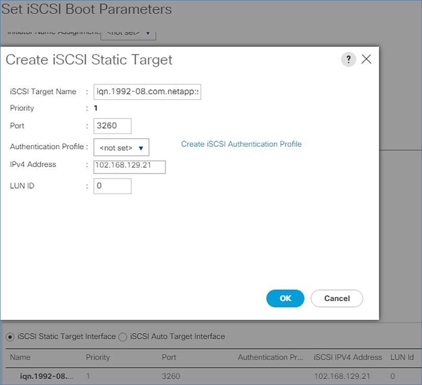
27. Enter the IP address of iscsi_lif_1b for the IPv4 Address field.
28. Click OK to add the iSCSI static target.
29. Click Add.
30. Enter the iSCSI Target Name.
31. Enter the IP address of iscsi_lif_2b for the IPv4 Address field.
32. Click OK to add the iSCSI static target.
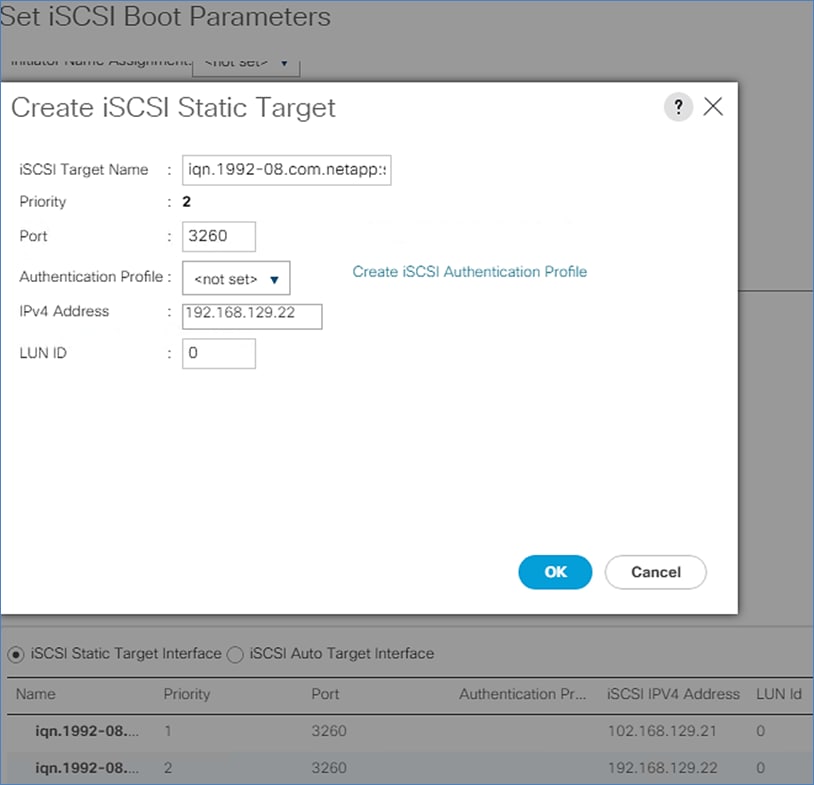
33. Click OK to complete setting the iSCSI Boot Parameters. Click Next.
Configure Maintenance Policy
To configure the maintenance policy, follow these steps:
1. Change the Maintenance Policy to default.
2. Click Next.
Configure Server Assignment
To configure the server assignment, follow these steps:
1. Select Assign Later for the Pool Assignment.
2. Under Firmware Management select HANA-Nodes-FW for Host Firmware Package from the dropdown list. Click Next.
Configure Operational Policies
To configure the operational policies, follow these steps:
1. In the BIOS Policy list, select HANA.
2. For Firmware Policies select HANA-Nodes-FW Host Firmware Package created earlier.
3. Expand Management IP Address: On Outband IPv4 tab, select ext-mgmt policy from the drop-down list for Management IP Address Policy.
4. Expand Power Control Policy Configuration and select HANA in the Power Control Policy list.
5. For Serial over LAN Policy select Sol-Console.
6. Choose default from drop-down list for the rest.
7. Click Finish to create the service profile template.
8. Click OK in the confirmation message.
Create Service Profiles for SAP HANA scale up system - example
To create service profiles from the service profile template with LAN connectivity policy single-host, to prepare a scale-up system based on RHEL8.0, for example, follow these steps:
1. Connect to Cisco UCS Manager and click Servers.
2. Select Service Profile Templates > root > Sub-Organizations > T01-HANA Organization > Service Template HANA-node
3. Right-click iSCSI-HANA-node and select Create Service Profiles from Template.
4. Enter singlehost-rhel as the service profile prefix.
5. Enter 01 as “Name Suffix Starting Number.”
6. Enter 1 as the “Number of Instances.”
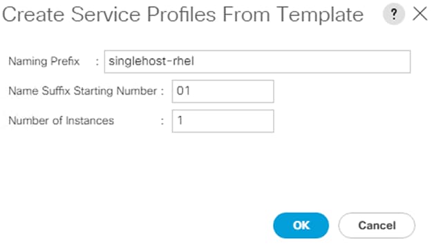
7. Click OK to create the service profile.
8. Click OK in the confirmation message.
Create Service Profiles for SAP HANA scale out system - Example
To create service profiles from the service profile template with LAN connectivity policy multi-host, to prepare a 4 node scale-out cluster based on SLES 15, follow these steps:
1. Connect to Cisco UCS Manager and click Servers.
2. Select Service Profile Templates > root > Sub-Organizations > T01-HANA Organization > Service Template HANA-node.
3. Right-click HANA-node and select Create Service Profiles from Template.
4. Enter multihost-sles as the service profile prefix.
5. Enter 1 as “Name Suffix Starting Number.”
6. Enter 4 as the “Number of Instances.”
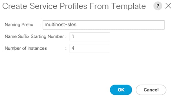
7. Click OK to create the service profiles.
8. Click OK in the confirmation message.
Complete Configuration Worksheet
Before running the setup script, complete the cluster setup worksheet in the ONTAP 9.6 Software Setup Guide located in the NetApp® ONTAP® 9 Documentation Center.
Configure ONTAP Nodes
Before running the setup script, review the configuration worksheets in the ONTAP 9.6 Software Setup Guide to learn about configuring ONTAP software. Table 4 lists the information needed to configure two ONTAP nodes. Customize the cluster detail values with the information applicable to your deployment.
Table 4 ONTAP Software Installation Prerequisites
| Cluster Detail |
Cluster Detail Value |
| Cluster node 01 IP address |
<node01-mgmt-ip> |
| Cluster node 01 netmask |
<node01-mgmt-mask> |
| Cluster node 01 gateway |
<node01-mgmt-gateway> |
| Cluster node 02 IP address |
<node02-mgmt-ip> |
| Cluster node 02 netmask |
<node02-mgmt-mask> |
| Cluster node 02 gateway |
<node02-mgmt-gateway> |
| Data ONTAP 9.6 URL |
<url-boot-software> |
Set Up ONTAP Cluster
Table 5 lists all the parameters required to set up the ONTAP cluster.
Table 5 ONTAP Cluster Prerequisites
| Cluster Detail |
Cluster Detail Value |
| Cluster name |
<clustername> |
| ONTAP base license |
<cluster-base-license-key> |
| NFS license key |
<nfs-license-key> |
| iSCSI license key |
<iscsi-license-key> |
| NetApp SnapRestore® license key |
<snaprestore-license-key> |
| NetApp SnapVault® license key |
<snapvault-license-key> |
| NetApp SnapMirror® license key |
<snapmirror-license-key> |
| NetApp FlexClone® license key |
<flexclone-license-key> |
| Cluster management IP address |
<clustermgmt-ip> |
| Cluster management netmask |
<clustermgmt-mask> |
| Cluster management gateway |
<clustermgmt-gateway> |
| Cluster node 01 IP address |
<node01-mgmt-ip> |
| Cluster node 01 netmask |
<node01-mgmt-mask> |
| Cluster node 01 gateway |
<node01-mgmt-gateway> |
| Cluster node 02 IP address |
<node02-mgmt-ip> |
| Cluster node 02 netmask |
<node02-mgmt-mask> |
| Cluster node 02 gateway |
<node02-mgmt-gateway> |
| Node 01 service processor IP address |
<node01-SP-ip> |
| Node 01 service processor IP netmask |
<node01-SP-mask> |
| Node 01 service processor IP gateway |
<node01-SP-gateway> |
| Node 02 service processor IP address |
<node02-SP-ip> |
| Node 02 service processor IP netmask |
<node02-SP-mask> |
| DNS domain name |
<dns-domain-name> |
| DNS server IP address |
<dns-ip> |
| Time zone |
<timezone> |
| NTP server IP address |
<ntp-ip> |
| SNMP contact information |
<snmp-contact> |
| SNMP location |
<snmp-location> |
| DFM server or another fault management server FQDN to receive SNMP traps |
<oncommand-um-server-fqdn> |
| SNMPv1 community string |
<snmp-community> |
| Mail host to send NetApp AutoSupport® messages |
<mailhost> |
| Storage admin email for NetApp AutoSupport |
<storage-admin-email> |
To set up an ONTAP cluster, follow these steps:
1. From a console port program attached to the storage controller A (node 01) console port, run the node setup script. This script appears when ONTAP 9.6 software boots on the node for the first time.
2. Follow the prompts to set up node 01:
Welcome to node setup.
You can enter the following commands at any time:
"help" or "?" - if you want to have a question clarified,
"back" - if you want to change previously answered questions, and
"exit" or "quit" - if you want to quit the setup wizard.
Any changes you made before quitting will be saved.
You can return to cluster setup at any time by typing “cluster setup”.
To accept a default or omit a question, do not enter a value.
This system will send event messages and weekly reports to NetApp Technical Support.
To disable this feature, enter "autosupport modify -support disable" within 24 hours.
Enabling AutoSupport can significantly speed problem determination and resolution should a problem occur on your system.
For further information on AutoSupport, see:
http://support.netapp.com/autosupport/
Type yes to confirm and continue {yes}: yes
Enter the node management interface port [e0M]: Enter
Enter the node management interface IP address: <node01-mgmt-ip>
Enter the node management interface netmask: <node01-mgmt-mask>
Enter the node management interface default gateway: <node01-mgmt-gateway>
A node management interface on port e0M with IP address <node01-mgmt-ip> has been created
Use your web browser to complete cluster setup by accessing https://<node01-mgmt-ip>
Otherwise press Enter to complete cluster setup using the command line interface:
![]() Cluster setup can also be done using the CLI guided setup. This document describes the cluster setup using - NetApp System Manager.
Cluster setup can also be done using the CLI guided setup. This document describes the cluster setup using - NetApp System Manager.
3. To complete the cluster setup, access https://<node01-mgmt-ip> with your web browser
Start the “Guided Cluster Setup”.
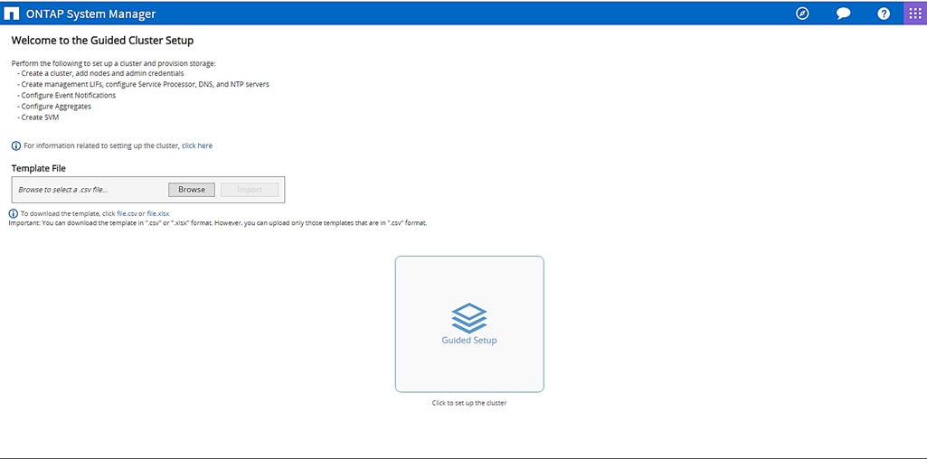
4. Provide the cluster name, the password of the user admin, and add all relevant licenses. Click Submit and Continue.
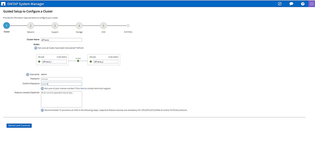
5. Provide the IP address, netmask, and gateway details for cluster management and choose the desired port. For example, select e0M for the first controller. Retain the settings for the node management by checking the box.
6. Provide the IP addresses for the Service Processor Management field. Check the boxes Override the Default Values and Retain Networks and Gateway Configuration of the Cluster Management. Finally, enter the DNS and NTP details.
![]() The node management interface can be on the same subnet as the cluster management interface, or it can be on a different subnet .
The node management interface can be on the same subnet as the cluster management interface, or it can be on a different subnet .
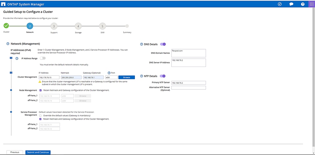
7. Enter the information for any needed event notifications.
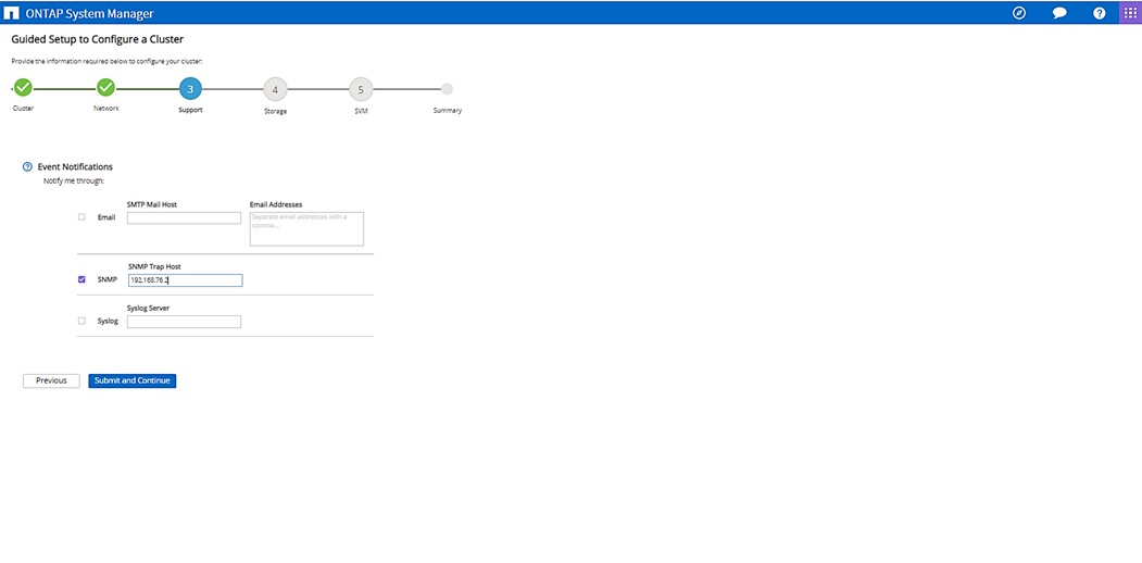
8. Skip the fourth step (Storage) without creating any aggregate. You will perform this step manually later.
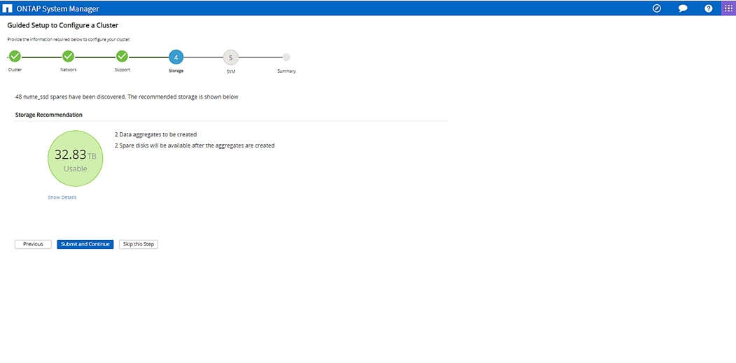
The Cluster has been successfully configured.
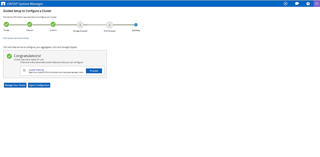
To log into the cluster, follow these steps:
1. Open an SSH connection to either the cluster IP or host name.
2. Log in to the admin user with the password you provided earlier.
Set Auto-Revert on Cluster Management
To set the auto-revert parameter on the cluster management interface, run the following command:
network interface modify –vserver <clustername> -lif cluster_mgmt –auto-revert true
![]() A storage virtual machine (SVM) is referred to as a Vserver (or vserver) in the GUI and CLI.
A storage virtual machine (SVM) is referred to as a Vserver (or vserver) in the GUI and CLI.
Set Up Management Broadcast Domain
By default, all network ports are included in the default broadcast domain. Network ports used for data services (for example, e0d, e1a, and e1e) should be removed from the default broadcast domain, leaving just the management network ports (e0c and e0M).
To make the changes, the following commands must be executed for each storage node. Storage nodes are named after the cluster name with an appended number.
broadcast-domain remove-ports –broadcast-domain Default –ports <clustername>_1:e1a,<clustername>_1:e1e, <clustername>_2:e1a,<clustername>_2:e1e
broadcast-domain show
Create Aggregates
![]() Advanced Data Partitioning (ADPv2) creates a root partition and two data partitions on each SSD drive in an All Flash FAS configuration. Disk auto assign should assign one data partition to each node in a high availability pair.
Advanced Data Partitioning (ADPv2) creates a root partition and two data partitions on each SSD drive in an All Flash FAS configuration. Disk auto assign should assign one data partition to each node in a high availability pair.
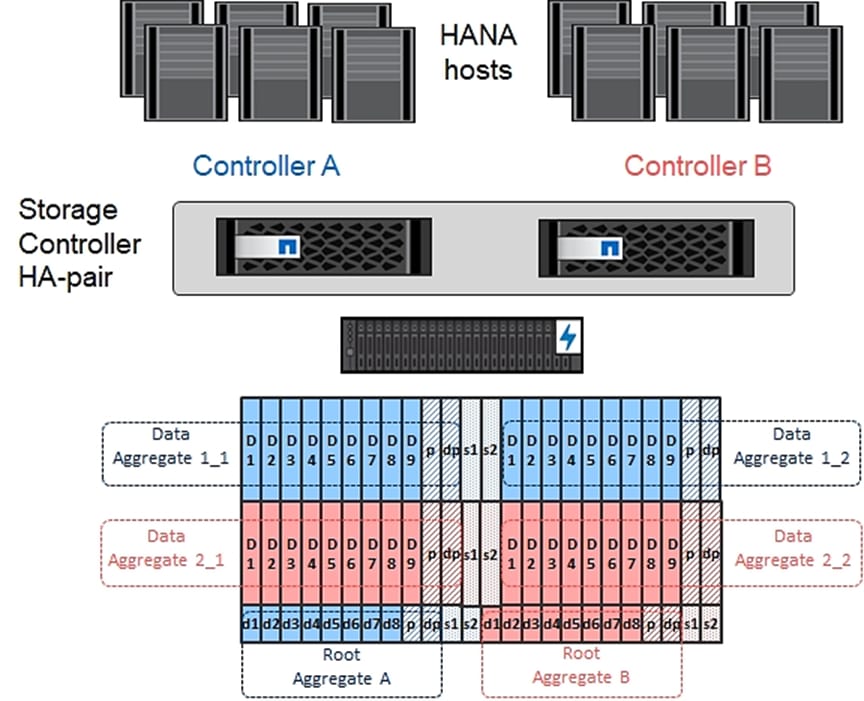
An aggregate containing the root volume for each storage controller is created during the ONTAP software setup process. To create additional aggregates, determine the aggregate name, the node on which to create it, and the number of disks it should contain.
1. To create new aggregates, run the following commands:
aggr create -aggregate aggr1_1 -node <clustername>_1 -diskcount 11
aggr create -aggregate aggr1_2 -node <clustername>_2 -diskcount 11
aggr create -aggregate aggr2_1 -node <clustername>_1 -diskcount 11
aggr create -aggregate aggr2_2 -node <clustername>_2 -diskcount 11
![]() Use all disks except for two spares to create the aggregates. In this example 11 disks per aggregate were used.
Use all disks except for two spares to create the aggregates. In this example 11 disks per aggregate were used.
![]() The aggregate cannot be created until disk zeroing completes. Run the aggr show command to display aggregate creation status. Do not proceed until all are online.
The aggregate cannot be created until disk zeroing completes. Run the aggr show command to display aggregate creation status. Do not proceed until all are online.
2. Optional: Rename the root aggregate on node 01 to match the naming convention for this aggregate on node 02. The aggregate is automatically renamed if system-guided setup is used.
aggr show
aggr rename –aggregate aggr0 –newname <node01-rootaggrname>
Verify Storage Failover
To confirm that storage failover is enabled, run the following commands for a failover pair:
1. Verify the status of storage failover.
storage failover show
![]() Both <clustername>_1 and <clustername>_2 must be capable of performing a takeover. Continue with step 3 if the nodes are capable of performing a takeover.
Both <clustername>_1 and <clustername>_2 must be capable of performing a takeover. Continue with step 3 if the nodes are capable of performing a takeover.
2. Enable failover on one of the two nodes.
storage failover modify -node <clustername>_1 -enabled true
![]() Enabling failover on one node enables it for both nodes.
Enabling failover on one node enables it for both nodes.
3. Verify the HA status for a two-node cluster.
![]() This step is not applicable for clusters with more than two nodes.
This step is not applicable for clusters with more than two nodes.
cluster ha show
4. Continue with step 6 if high availability is configured.
5. Only enable HA mode for two-node clusters. Do not run this command for clusters with more than two nodes because it causes problems with failover.
cluster ha modify -configured true
Do you want to continue? {y|n}: y
6. Verify that hardware assist is correctly configured and, if needed, modify the partner IP address.
storage failover hwassist show
storage failover modify –hwassist-partner-ip <node02-mgmt-ip> -node <clustername>_1
storage failover modify –hwassist-partner-ip <node01-mgmt-ip> -node <clustername>_2
Disable Flow Control on 40/100GbE Ports
NetApp recommends disabling flow control on all the 40/100GbE ports that are connected to external devices. To disable flow control, follow these steps:
1. Run the following commands to configure node 1:
network port modify -node <clustername>_1 -port e1a,e1e -flowcontrol-admin none
Warning: Changing the network port settings will cause a several second interruption in carrier.
Do you want to continue? {y|n}: y
2. Run the following commands to configure node 2:
network port modify -node <clustername>_2 -port e1a,e1e -flowcontrol-admin none
Warning: Changing the network port settings will cause a several second interruption in carrier.
Do you want to continue? {y|n}: y
network port show –fields flowcontrol-admin
Configure AutoSupport
NetApp AutoSupport® sends support summary information to NetApp through HTTPS. To configure AutoSupport, run the following command:
system node autosupport modify -node * -state enable –mail-hosts <mailhost> -transport https -support enable -noteto <storage-admin-email>
Enable Cisco Discovery Protocol
To enable the Cisco Discovery Protocol (CDP) on the NetApp storage controllers, run the following command:
node run -node * options cdpd.enable on
![]() To be effective, CDP must also be enabled on directly connected networking equipment such as switches and routers.
To be effective, CDP must also be enabled on directly connected networking equipment such as switches and routers.
Create Broadcast Domains
Figure 72 shows the physical network connection and the virtual LANs (VLANs) used for this setup.
Figure 72 Physical Network Connection and VLANs
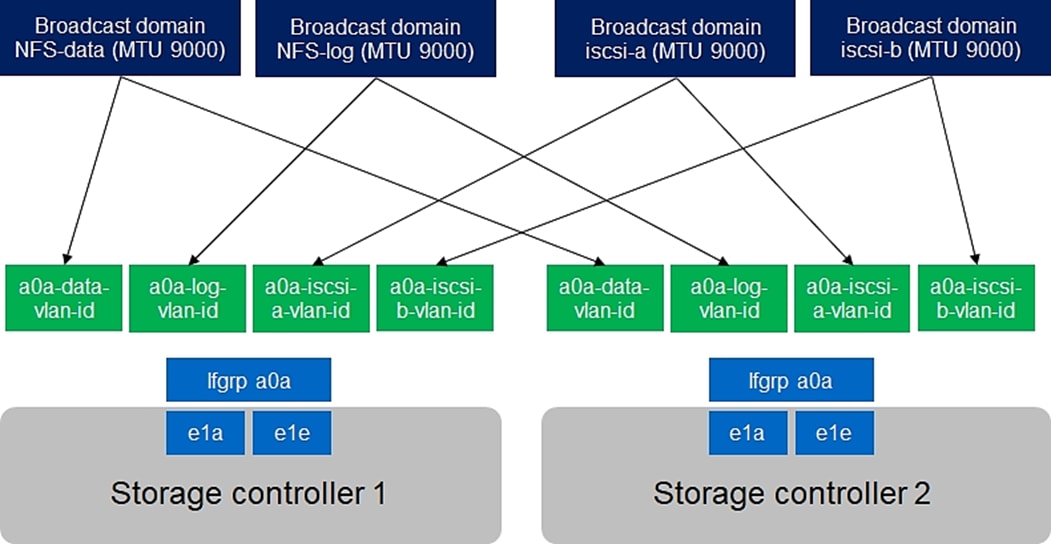
Table 6 Cluster Networking Requirements
| Cluster Detail |
Cluster Detail Value |
Value Used in CVD Setup |
| NFS data VLAN ID |
<data-vlan-id> |
201 |
| NFS Log VLAN ID |
<log-vlan-id> |
228 |
| iSCSI a VLAN ID |
<iscsi-a-vlan-id> |
128 |
| iSCSI b VLAN ID |
<iscsi-b-vlan-id> |
129 |
| Storage backend VLAN ID |
<stbackend-vlan-id> |
224 |
All broadcast domains must be created with an MTU size of 9000 (jumbo frames):
broadcast-domain create -broadcast-domain NFS-data -mtu 9000
broadcast-domain create -broadcast-domain NFS-log -mtu 9000
broadcast-domain create -broadcast-domain iSCSI-a -mtu 9000
broadcast-domain create -broadcast-domain iSCSI-b -mtu 9000
broadcast-domain create -broadcast-domain storage-backend -mtu 9000
Create Interface Groups
To create the LACP interface groups for the 40GbE data interfaces, run the following commands:
ifgrp create -node <clustername>_1 -ifgrp a0a -distr-func port -mode multimode_lacp
ifgrp add-port -node <clustername>_1 -ifgrp a0a -port e1a
ifgrp add-port -node <clustername>-_1 -ifgrp a0a -port e1e
ifgrp create -node <clustername>_2 -ifgrp a0a -distr-func port -mode multimode_lacp
ifgrp add-port -node <clustername>_2 -ifgrp a0a -port e1a
ifgrp add-port -node <clustername>_2 -ifgrp a0a -port e1e
ifgrp show
Create VLANs
To create VLANs, follow these steps:
1. Set the MTU size of the interface groups.
network port modify –node <clustername>_1 -port a0a –mtu 9000
network port modify –node <clustername>_2 -port a0a –mtu 9000
2. Create HANA data VLAN ports and add them to the NFS-Data broadcast domain.
network port vlan create –node <clustername>_1 -vlan-name a0a-<data-vlan-id>
network port vlan create –node <clustername>_2 -vlan-name a0a-<data-vlan-id>
broadcast-domain add-ports -broadcast-domain NFS-Data -ports <clustername>-1:a0a-<data-vlan-id>, <clustername>-02:a0a-<data-vlan-id>
3. Create HANA log VLAN ports and add them to the NFS-Log broadcast domain.
network port vlan create –node <clustername>_1 -vlan-name a0a-<log-vlan-id>
network port vlan create –node <clustername>_2 -vlan-name a0a-<log-vlan-id>
broadcast-domain add-ports -broadcast-domain NFS-Log -ports,<clustername>-01:a0a-<log-vlan-id>, <clustername>-02:a0a-<log-vlan-id>
4. Create the iSCSI-a VLAN ports and add them to the iSCSI-a broadcast domain.
network port vlan create –node <clustername>_1 -vlan-name a0a-<iscsi-a-vlan-id>
network port vlan create –node <clustername>_2 -vlan-name a0a-<iscsi-a-vlan-id>
broadcast-domain add-ports -broadcast-domain iSCSI-a -ports,<clustername>-01:a0a-<iscsi-a-vlan-id>, <clustername>-02:a0a-<iscsi-a-vlan-id>
5. Create the iSCSI-b VLAN ports and add them to the iSCSI-b broadcast domain.
network port vlan create –node <clustername>_1 -vlan-name a0a-<iscsi-b-vlan-id>
network port vlan create –node <clustername>_2 -vlan-name a0a-<iscsi-b-vlan-id>
broadcast-domain add-ports -broadcast-domain iSCSI-b -ports,<clustername>-01:a0a-<iscsi-b-vlan-id>, <clustername>-02:a0a-<iscsi-b-vlan-id>
6. Create backup VLAN ports and add them to the backup domain.
network port vlan create –node <clustername>_1 -vlan-name a0a-<backup-vlan-id>
network port vlan create –node <clustername>_2 -vlan-name a0a-<backup-vlan-id>
broadcast-domain add-ports -broadcast-domain storage-backend -ports <clustername>_1:a0a-<backup-vlan-id>, <clustername>_2:a0a-<backup-vlan-id>
Configure HTTPS Access
For each of the SVMs and the cluster node, create a certificate to allow secure communication with HTTPS. For each of the certificates, specify the individual values listed in Table 7.
Table 7 ONTAP Software Parameters Needed to Enable HTTPS
| Cluster Detail |
Cluster Detail Value |
| Certificate common name |
<cert-common-name> |
| Country code |
<cert-country> |
| State |
<cert-state> |
| Locality |
<cert-locality> |
| Organization |
<cert-org> |
| Unit |
<cert-unit> |
| |
<cert-email> |
| Number of days the certificate is valid |
<cert-days> |
To configure secure access to the storage controller, follow these steps:
1. Increase the privilege level to access the certificate commands.
set -privilege diag
Do you want to continue? {y|n}: y
2. Generally, a self-signed certificate is already in place. Verify the certificate and obtain parameters (for example the <serial-number>) by running the following command:
security certificate show
3. For each SVM shown, the certificate common name should match the DNS FQDN of the SVM. Delete the two default certificates and replace them with either self-signed certificates or certificates from a certificate authority (CA). To delete the default certificates, run the following commands:
security certificate delete -vserver hana-svm -common-name hana-svm -ca hana-svm -type server -serial <serial-number>
![]() Deleting expired certificates before creating new certificates is a best practice. Run the security certificate delete command to delete the expired certificates. In the following command, use tab completion to select and delete each default certificate.
Deleting expired certificates before creating new certificates is a best practice. Run the security certificate delete command to delete the expired certificates. In the following command, use tab completion to select and delete each default certificate.
4. To generate and install self-signed certificates, run the following commands as one-time commands. Generate a server certificate for the Infra-SVM, the HANA SVM, and the cluster SVM. Use tab completion to aid in the completion of these commands.
security certificate create -common-name <cert-common-name> -type server -size 2048 -country <cert-country> -state <cert-state> -locality <cert-locality> -organization <cert-org> -unit <cert-unit> -email-addr <cert-email> -expire-days <cert-days> -protocol SSL -hash-function SHA256 -vserver hana-svm
security certificate create -common-name <cert-common-name> -type server -size 2048 -country <cert-country> -state <cert-state> -locality <cert-locality> -organization <cert-org> -unit <cert-unit> -email-addr <cert-email> -expire-days <cert-days> -protocol SSL -hash-function SHA256 -vserver infra-svm
security certificate create -common-name <cert-common-name> -type server -size 2048 -country <cert-country> -state <cert-state> -locality <cert-locality> -organization <cert-org> -unit <cert-unit> -email-addr <cert-email> -expire-days <cert-days> -protocol SSL -hash-function SHA256 -vserver <clustername>
5. To obtain the values for the parameters required in the next step (<cert-ca> and <cert-serial>), run the security certificate show command.
6. Enable each certificate that was just created by using the –server-enabled true and –client-enabled false parameters. Use tab completion to aid in the completion of these commands.
security ssl modify -vserver <clustername> -server-enabled true -client-enabled false -ca <cert-ca> -serial <cert-serial> -common-name <cert-common-name>
security ssl modify -vserver hana-svm -server-enabled true -client-enabled false -ca <cert-ca> -serial <cert-serial> -common-name <cert-common-name>
security ssl modify -vserver infra-svm -server-enabled true -client-enabled false -ca <cert-ca> -serial <cert-serial> -common-name <cert-common-name>
7. Disable HTTP cluster management access.
system services firewall policy delete -policy mgmt -service http –vserver <clustername>
![]() It is normal for some of these commands to return an error message stating that the entry does not exist.
It is normal for some of these commands to return an error message stating that the entry does not exist.
8. Change back to the normal admin privilege level and set up the system so that SVM logs are available through the web.
set –privilege admin
vserver services web modify –name spi|ontapi|compat –vserver * -enabled true
Configure SVM for the Infrastructure
Figure 73 and Table 8 describe the infrastructure SVM together with all required storage objects (volumes, export-policies, and LIFs).
Figure 73 Overview of Infrastructure SVM Components
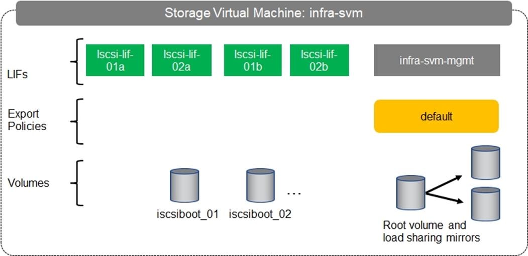
Table 8 ONTAP Software Parameters for Infrastructure SVMs
| Cluster Detail |
Cluster Detail Value |
Value used in CVD setup |
| Infrastructure SVM management IP |
<infra-svm-ip> |
192.168.76.46 |
| Infrastructure SVM management IP netmask |
<infra-svm-netmask> |
255.255.255.0 |
| Infrastructure SVM default gateway |
<infra-svm-gateway> |
192.168.76.1 |
| iSCSI a CIDR |
<iscsi-a-cidr> |
192.168.128.0 |
| iSCSI a Netmask |
<iscsi_a_netmask> |
255.255.255.0 |
| iSCSI a IP node 1 |
<node01_iscsi_lif01a_ip> |
192.168.128.21 |
| iSCSI a IP node 2 |
<node02_iscsi_lif02a_ip> |
192.168.128.22 |
| iSCSI b CIDR |
<iscsi-b-cidr> |
192.168.129.0 |
| iSCSI b Netmask |
<iscsi_b_netmask> |
255.255.255.0 |
| iSCSI b IP node 1 |
<node01_iscsi_lif01b_ip> |
192.168.129.21 |
| iSCSI b IP node 2 |
<node02_iscsi_lif02b_ip> |
192.168.129.22 |
| IQN of Node 1 |
<server-host-infra-01-iqn> |
iqn.2020-03.com.flexpod:hana-node:1 |
| IQN of Node 2 |
<server-host-infra-02-iqn> |
iqn.2020-03.com.flexpod:hana-node:2 |
Create SVM for the Infrastructure
To create an infrastructure SVM, follow these steps:
1. Run the vserver create command.
vserver create –vserver infra-svm –rootvolume infra_rootvol –aggregate aggr2_1 –rootvolume-security-style unix
2. Select the SVM data protocols to configure, keeping iSCSI and NFS.
vserver remove-protocols –vserver infra-svm -protocols fcp,cifs,ndmp
3. Add the data aggregates to the SVM aggregate list .
vserver modify –vserver infra-svm –aggr-list aggr1_1,aggr2_1,aggr1_2,aggr2_2
4. Enable and run the NFS protocol in the SVM.
nfs create -vserver infra-svm -udp disabled
Create Load-Sharing Mirrors
To create a load-sharing mirror of an SVM root volume, follow these steps:
1. Create a volume to be the load-sharing mirror of the infrastructure SVM root volume on each node.
volume create –vserver infra-svm –volume infra_rootvol_m01 –aggregate aggr2_1 –size 1GB –type DP
volume create –vserver infra-svm –volume infra_rootvol_m02 –aggregate aggr2_2 –size 1GB –type DP
2. Create the mirroring relationships.
snapmirror create –source-path infra-svm:infra_rootvol –destination-path
infra-svm:infra_rootvol_m01 –type LS -schedule 5min
snapmirror create –source-path infra-svm:infra_rootvol –destination-path
infra-svm:infra_rootvol_m02 –type LS -schedule 5min
3. Initialize the mirroring relationship.
snapmirror initialize-ls-set –source-path infra-svm:infra_rootvol
snapmirror show
Create Export Policies for the Root Volumes
To configure to export policies on the SVM, follow these steps:
1. Create a new rule for the infrastructure NFS subnet in the default export policy.
vserver export-policy rule create –vserver infra-svm -policyname default –ruleindex 1 –protocol nfs -clientmatch 0.0.0.0/0 -rorule sys –rwrule sys -superuser sys –allow-suid true –anon 0
2. Assign the export policy to the infrastructure SVM root volume.
volume modify –vserver infra-svm –volume infra_rootvol –policy default
Add Infrastructure SVM Management LIF
To add the infrastructure SVM administration LIF in the out-of-band management network, follow these steps:
1. Run the following commands:
network interface create –vserver infra-svm –lif infra-svm-mgmt -service-policy default-management –role data –data-protocol none –home-node <clustername>_2 -home-port e0M –address <infra-svm-ip> -netmask <infra-svm-mask> -status-admin up –failover-policy broadcast-domain-wide –firewall-policy mgmt –auto-revert true
![]() The SVM management IP in this step should be in the same subnet as the storage cluster management IP.
The SVM management IP in this step should be in the same subnet as the storage cluster management IP.
2. Create a default route to allow the SVM management interface to reach the outside world.
network route create –vserver infra-svm -destination 0.0.0.0/0 –gateway <infra-svm-gateway>
Create iSCSI LIFs
To create the four iSCSI LIFs (two on each node), run the following commands:
network interface create -vserver infra-svm -lif iscsi_lif01a -role data -data-protocol iscsi -home-node <clustername>_01 -home-port a0a-<iscsi-a-vlan-id> -address <node01_iscsi_lif01a_ip> -netmask <iscsi_a_netmask> –status-admin up –failover-policy disabled –firewall-policy data –auto-revert false
network interface create -vserver infra-svm -lif iscsi_lif01b -role data -data-protocol iscsi -home-node <clustername>_01 -home-port a0a-<iscsi-b-vlan-id> -address <node01_iscsi_lif01b_ip> -netmask <iscsi_b_netmask> –status-admin up –failover-policy disabled –firewall-policy data –auto-revert false
network interface create -vserver infra-svm -lif iscsi_lif02a -role data -data-protocol iscsi -home-node <clustername>_02 -home-port a0a-<iscsi-a-vlan-id> -address <node02_iscsi_lif02a_ip> -netmask <iscsi_a_netmask> –status-admin up –failover-policy disabled –firewall-policy data –auto-revert false
network interface create -vserver infra-svm -lif iscsi_lif02b -role data -data-protocol iscsi -home-node <clustername>_02 -home-port a0a-<iscsi-b-vlan-id> -address <node02_iscsi_lif02b_ip> -netmask <iscsi_b_netmask > –status-admin up –failover-policy disabled –firewall-policy data –auto-revert false
Create Block Protocol (iSCSI) Service
Run the following command to create the iSCSI service. This command also starts the iSCSI service and sets the iSCSI Qualified Name (IQN) for the SVM.
iscsi create -vserver infra-svm
Create FlexVol Volumes
To create FlexVol volumes, run the following commands:
volume create -vserver infra-svm -volume iscsiboot_01 -aggregate aggr1_1 -size 1000GB -state online -space-guarantee none -percent-snapshot-space 0
snapmirror update-ls-set -source-path infra-svm:infra_rootvol
Configure LUNs for iSCSI Boot
Create Boot LUNs for Servers
To create boot LUNs, run the following commands:
lun create -vserver infra-svm -volume iscsiboot_01 -lun server-01 -size 80GB -ostype linux -space-reserve disabled
lun create -vserver infra-svm -volume iscsiboot_01 -lun server-02 -size 80GB -ostype linux -space-reserve disabled
The example above created boot LUNs for two servers. Repeat the command with a different LUN name to create additional boot LUNs for additional servers.
Create Portset
To create a portset that includes all iSCSI LIFs, run the following commands:
portset create -vserver infra-svm -portset server_Portset -protocol iscsi -port-name iscsi_lif01a,iscsi_lif01b,iscsi_lif02a,iscsi_lif02b
Create igroups
To create igroups, run the following commands:
igroup create –vserver infra-svm –igroup server-01 –protocol iscsi –ostype linux –initiator <server-host-infra-01-iqn> -portset server_Portset
igroup create –vserver infra-svm –igroup server-02 –protocol iscsi –ostype linux –initiator <server-host-infra-02-iqn> -portset server_Portset
Repeat the command by using the IQN name of additional servers to create additional igroups for additional servers
Map Boot LUNs to igroups
To map server boot LUNs to igroups, run the following commands:
lun map –vserver infra-svm –volume iscsiboot_01 –lun server-01 –igroup server-01 –lun-id 0
lun map –vserver infra-svm –volume iscsiboot_01 –lun server-02 –igroup server-02 –lun-id 0
Repeat the command to map additional boot LUNs to additional servers
Configure SVM for HANA
Figure 74 and Table 9 describe the HANA SVM together with all the required storage objects (volumes, export-policies, and LIFs). The HANA specific data, log, and shared volumes are explained in the section Important SAP Notes.
Figure 74 Overview of SAP HANA SVM Components
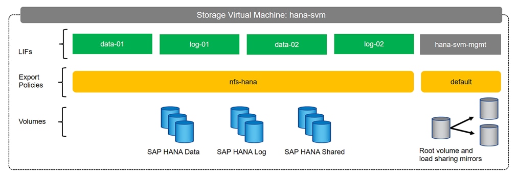
Table 9 ONTAP Software Parameter for HANA SVM
| Cluster Detail |
Cluster Detail Value |
Value used in CVD setup |
| HANA SVM management IP |
<hana-svm-ip> |
192.168.76.47 |
| HANA SVM management IP netmask |
<hana-svm-netmask> |
255.255.255.0 |
| HANA SVM default gateway |
<hana-svm-gateway> |
192.168.76.1 |
| NFS Data CIDR |
<data-cidr> |
192.168.201.0 |
| NFS Data netmask |
<data-netmask> |
255.255.255.0 |
| NFS Data LIF node 1 IP |
<node01-data_lif01-ip> |
192.168.201.21 |
| NFS Data LIF node 2 IP |
<node02-data_lif02-ip> |
192.168.201.22 |
| NFS log CIDR |
<log-cidr> |
192.168.228.0 |
| NFS Log netmask |
<log-netmask> |
255.255.255.0 |
| NFS Log LIF node 1 IP |
<node01-log_lif01-ip> |
192.168.228.21 |
| NFS Log LIF node 2 IP |
<node02-log_lif02-ip> |
192.168.228.22 |
Create SVM for SAP HANA
To create an SVM for SAP HANA volumes, follow these steps:
1. Run the vserver create command.
vserver create –vserver hana-svm –rootvolume hana_rootvol –aggregate aggr1_2 –rootvolume-security-style unix
2. Select the SVM data protocols to configure, keeping NFS.
vserver remove-protocols –vserver hana-svm -protocols fcp,cifs,iscsi,nvme
3. Add the two data aggregates to the hana-svm aggregate list.
vserver modify –vserver hana-svm –aggr-list aggr1_1,aggr1_2,aggr2_1,aggr2_2
4. Enable and run the NFS protocol in the Infra-SVM.
nfs create -vserver hana-svm -v4.1 enabled -v4.1-pnfs enabled -v4.1-read-delegation disabled -v4.1-write-delegation disabled -v4.1-acl disabled -v4-numeric-ids disabled -udp disabled
5. Enable a large NFS transfer size.
set advanced
vserver nfs modify –vserver hana-svm –tcp-max-transfersize 1048576
set admin
6. Set the NFSv4 ID domain.
nfs modify -vserver hana-svm -v4-id-domain nfsv4domain.flexpod.com
7. Set the NFSv4 lease time.
set advanced
nfs modify -vserver hana-svm -v4-lease-seconds 10
set admin
8. Set the group ID of the user root to 0.
vserver services unix-user modify -vserver hana-svm -user root -primary-gid 0
Create Load-Sharing Mirrors
To create a load-sharing mirror of an SVM root volume, follow these steps:
1. Create a volume to be the load-sharing mirror of the HANA SVM root volume on each node.
volume create –vserver hana-svm –volume hana_rootvol_m01 –aggregate aggr2_1 –size 1GB –type DP
volume create –vserver hana-svm –volume hana_rootvol_m02 –aggregate aggr2_2 –size 1GB –type DP
2. Create the mirroring relationships.
snapmirror create –source-path hana-svm:hana_rootvol –destination-path hana-svm:hana_rootvol_m01 –type LS -schedule 5min
snapmirror create –source-path hana-svm:hana_rootvol –destination-path hana-svm:hana_rootvol_m02 –type LS -schedule 5min
3. Initialize the mirroring relationship.
snapmirror initialize-ls-set –source-path hana-svm:hana_rootvol
Create Export Policies for the Root Volumes
To configure the NFS export policies on the SVM, follow these steps:
1. Create a new rule for the infrastructure NFS subnet in the default export policy.
vserver export-policy rule create –vserver hana-svm -policyname default –ruleindex 1 –protocol nfs -clientmatch 0.0.0.0/0 -rorule sys –rwrule sys -superuser sys –allow-suid true
2. Assign the FlexPod export policy to the infrastructure SVM root volume.
volume modify –vserver hana-svm –volume hana_rootvol –policy default
Add HANA SVM Management Interface and Administrator
To add the HANA SVM administrator and SVM administration LIF in the out-of-band management network, follow these steps:
1. Run the following commands:
network interface create –vserver hana-svm –lif hana-svm-mgmt -service-policy default-management –role data –data-protocol none –home-node <clustername>-02 -home-port e0M –address <hana-svm-ip> -netmask <hana-svm-netmask> -status-admin up –failover-policy broadcast-domain-wide –firewall-policy mgmt –auto-revert true
![]() The SVM management IP in this step should be in the same subnet as the storage cluster management IP.
The SVM management IP in this step should be in the same subnet as the storage cluster management IP.
2. Create a default route to allow the SVM management interface to reach the outside world.
network route create –vserver hana-svm -destination 0.0.0.0/0 –gateway <hana-svm-gateway>
3. Set a password for the SVM vsadmin user and unlock the user.
security login password –username vsadmin –vserver hana-svm
Enter a new password: <password>
Enter it again: <password>
security login unlock –username vsadmin –vserver hana-svm
Create Export Policies for the HANA SVM
1. Create a new export policy for the HANA data and log subnet.
vserver export-policy create -vserver hana-svm -policyname nfs-hana
2. Create a rule for this policy.
vserver export-policy rule create -vserver hana-svm -policyname nfs-hana -clientmatch <data-cidr>,<log-cidr> -rorule sys -rwrule sys -allow-suid true -allow-dev true -ruleindex 1 -protocol nfs -superuser sys
Create NFS LIF for SAP HANA Data
To create the NFS LIFs for SAP HANA data, run the following commands:
network interface create -vserver hana-svm -lif data-01 -role data -data-protocol nfs -home-node <clustername>-01 -home-port a0a-<data-vlan-id> –address <node01-data_lif01-ip> -netmask <data-netmask> -status-admin up –failover-policy broadcast-domain-wide –firewall-policy data –auto-revert true
network interface create -vserver hana-svm -lif data-02 -role data -data-protocol nfs -home-node <clustername>-02 -home-port a0a-<data-vlan-id> –address <node02-data_lif02-ip> -netmask <data-netmask> -status-admin up –failover-policy broadcast-domain-wide –firewall-policy data –auto-revert true
Create NFS LIF for SAP HANA Log
To create an NFS LIF for SAP HANA log, run the following commands:
network interface create -vserver hana-svm -lif log-01 -role data -data-protocol nfs -home-node <clustername>-01 -home-port a0a-<log-vlan-id> –address <node01-log_lif01-ip> -netmask <log-netmask> -status-admin up –failover-policy broadcast-domain-wide –firewall-policy data –auto-revert true
network interface create -vserver hana-svm -lif log-02 -role data -data-protocol nfs -home-node <clustername>-02 -home-port a0a-<log-vlan-id> –address <node02-log_lif02-ip> -netmask <log-netmask> -status-admin up –failover-policy broadcast-domain-wide –firewall-policy data –auto-revert true
status-admin up –failover-policy broadcast-domain-wide –firewall-policy data –auto-revert true
This section details the preparation of HANA nodes based on SLES for SAP 15 SP1 and RHEL 8.0.
SAP HANA Node OS Preparation – RHEL for SAP HANA 8.0
Base OS Installation
To install the OS, follow these steps:
![]() The following procedure shows the RHEL 8.0 installation procedure. Keep the RHEL DVD handy.
The following procedure shows the RHEL 8.0 installation procedure. Keep the RHEL DVD handy.
This section provides the procedure for Red Hat Enterprise Linux 8.0 Operating System and customizing for SAP HANA requirement.
![]() RHEL 8 must be installed and configured according to SAP note https://launchpad.support.sap.com/#/notes/2772999
RHEL 8 must be installed and configured according to SAP note https://launchpad.support.sap.com/#/notes/2772999
To install the RHEL 8.0 system, follow these steps:
1. Prepare the iSCSI LUN like described in the Storage part of this CVD for the OS.
2. In Cisco UCS Manager, click the Servers tab in the navigation pane.
3. Select Service Profiles > root > HANA-Server01.
4. Click KVM Console.
5. When the KVM Console is launched, click Boot Server.
6. If you using CD click Virtual Media > Activate Virtual Devices.
7. Select Accept this Session for Unencrypted Virtual Media Session then click Apply.
8. Click Virtual Media and Choose Map CD/DVD.
9. Click Browse to navigate ISO media location. Select the rhel-8.0-x86_64-dvd iso file.
10. Click Map Device.
11. During the boot time the iSCSI targets must be shown. If not check the iSCSI configuration.
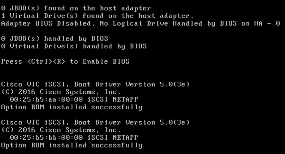
12. After the POST the system will boot from the RHEL ISO.
13. At the prompt of the Installation options: Press the Tab key to alter the command line options. Append parameter ip=ibft to the kernel command line as shown below. You could change to traditional ethernet device names by setting with net.ifnames=0. At this time, you can also disable IPv6 support with ipv6.disable=1.
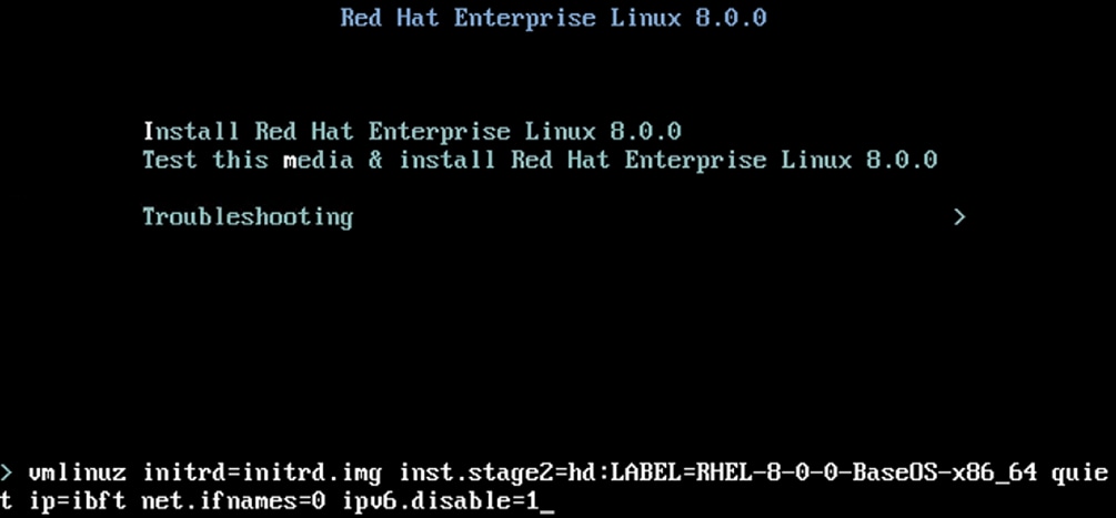
This is added to make sure the iSCSI targets are discovered appropriately.
14. Under Localization - Choose Keyboard and Language of your choice. Configure the appropriate time and date.
15. Under Software. Leave the Software section select Server.
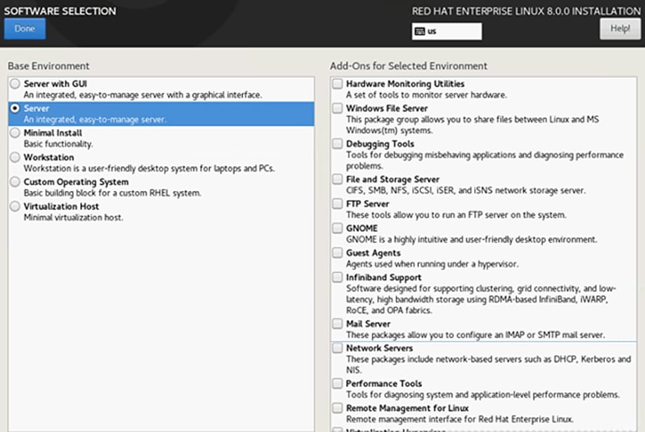
16. Under System, click the ‘Security Policy’ to set the security policy to OFF.
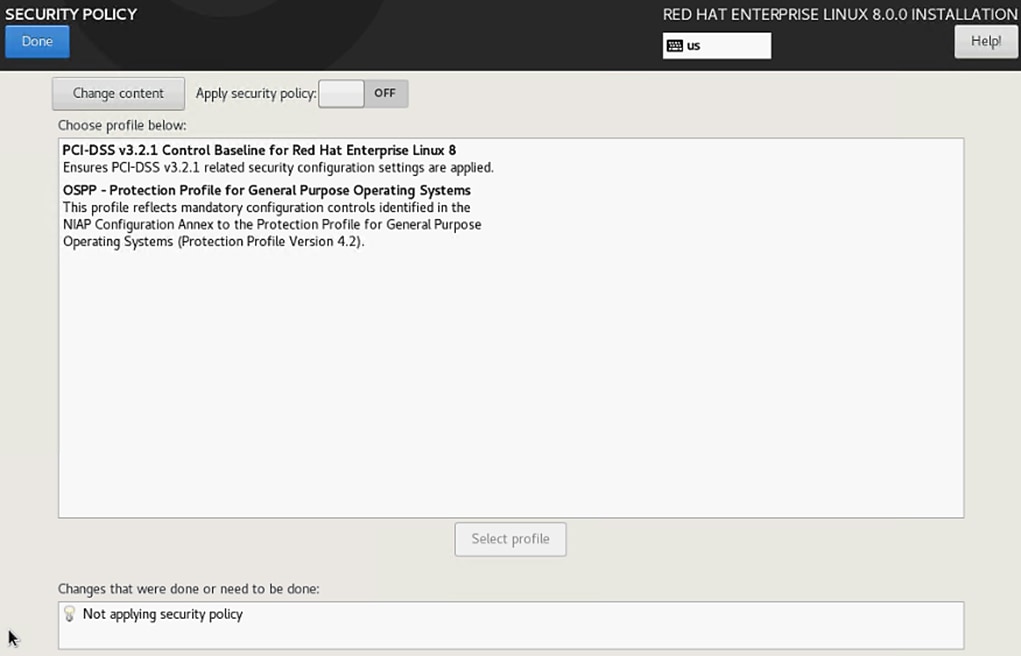
17. Disable KDUMP.
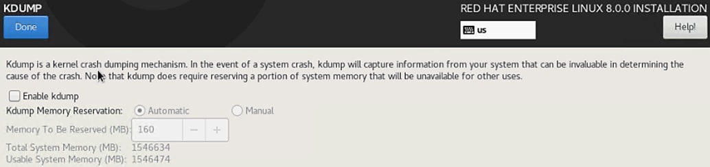
18. For System Purpose- make the appropriate selection based on your use case. For the validation system, usage has been set to Dev/test and SLA “Not Specified”. Use the correct values based on your implementation scenario.
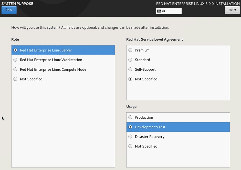
19. Installation destination - The screen lists all the local standard disks, if any. Click Specialized and Network Disks section – “Add a Disk”. Select the discovered iSCSI boot LUN multipath device and click Done.
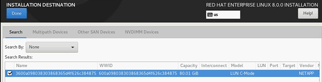
20. Click Done. Select “Custom’ for storage configuration. Click Done.
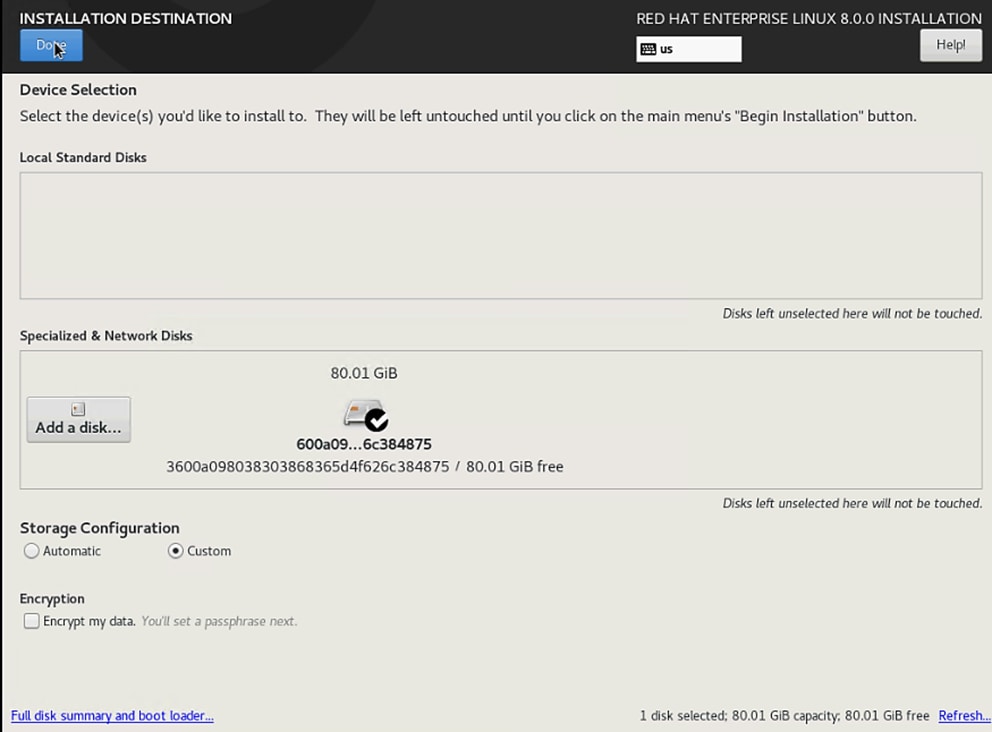
21. Select Standard Partition and then select “Click here to create them automatically.”
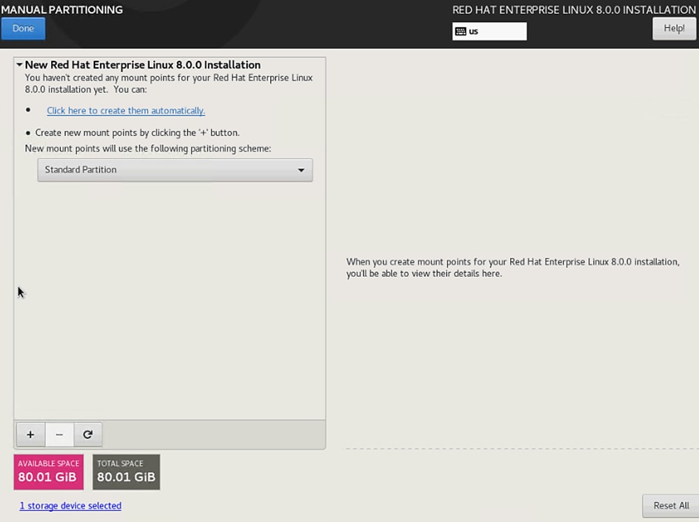
22. Alter the default Partition table to suit your requirement.. Click Done. Accept Changes.
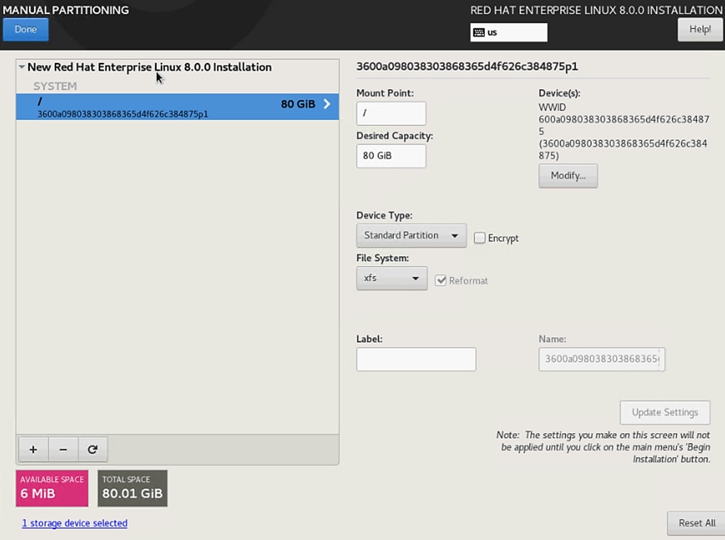
23. Click Begin Installation and then setup the root password and create more users if needed.
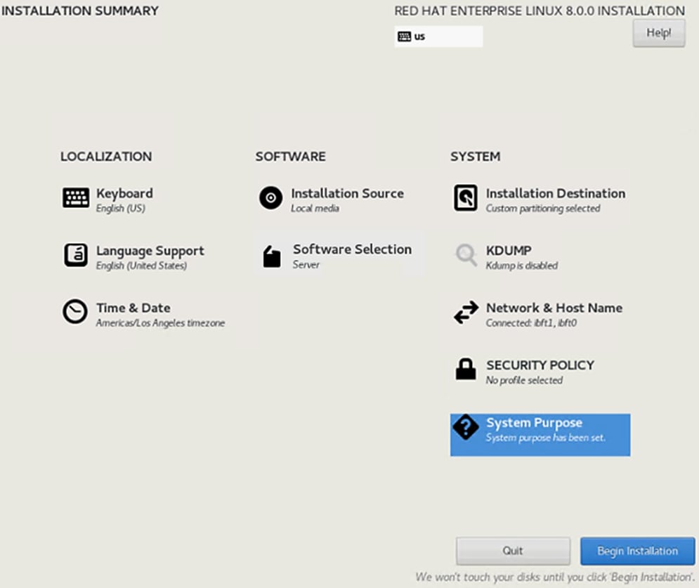
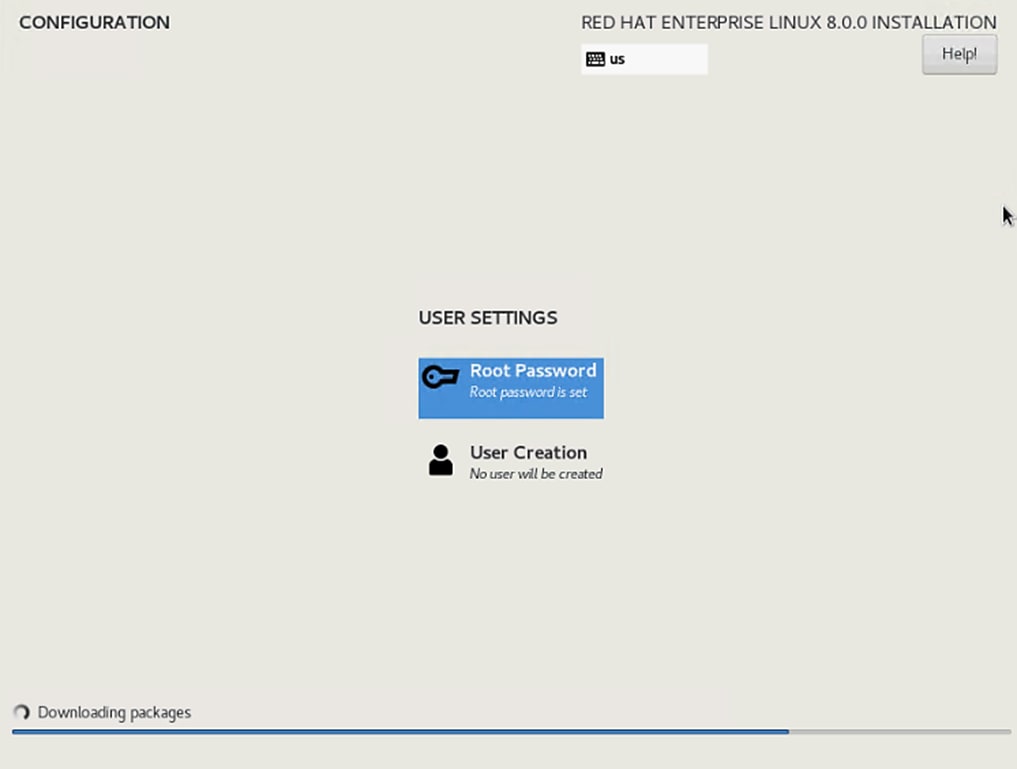
24. Installation completes. Click Reboot.
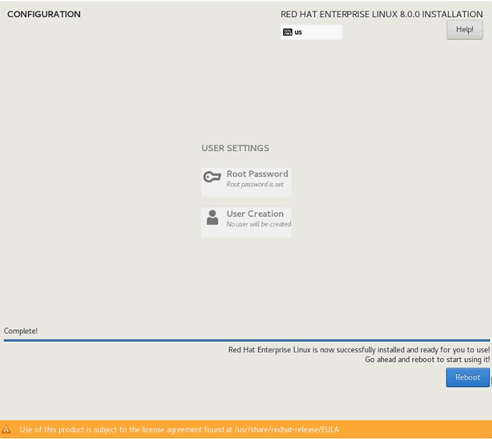
Post Installation Tasks
Configure the Network
To configure the network, follow these steps:
1. List the ethernet interfaces that are with standard naming convention and prepare to assign the IP addresses in various networks/subnets.
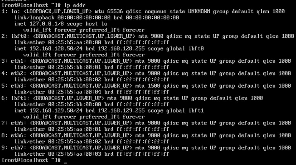
2. Configure the interfaces, system hostname . Identify the Admin/Mgmt vNIC using the MAC address to eth interface mapping at the OS level with “ip address” command [as above] and on the Network tab of service profile under the vNICs. Compare to map the ip address to eth interfaces based on this.
![]() The iSCSI vNICs appear as ibft0 with ifcfg-eth0 interface config file and other iSCSI vNIC as ibft1 and correspondingly ifcfg-eth4 config file. We will have to create the other interface config files -> ifcfg-eth1, ifcfg-eth2, ifcfg-eth3, ifcfg-eth5, ifcfg-eth6 and ifcfg-eth7 files.
The iSCSI vNICs appear as ibft0 with ifcfg-eth0 interface config file and other iSCSI vNIC as ibft1 and correspondingly ifcfg-eth4 config file. We will have to create the other interface config files -> ifcfg-eth1, ifcfg-eth2, ifcfg-eth3, ifcfg-eth5, ifcfg-eth6 and ifcfg-eth7 files.
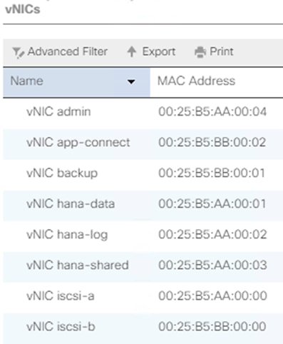
3. Create the configuration file for the interface as below. Default Route and Gateway setting are done at the interface level.
#cd /etc/sysconfig/network-scripts
#vi ifcfg-eth1
TYPE=Ethernet
BOOTPROTO=static
DEFROUTE=no
IPV4_FAILURE_FATAL=no
NAME=backup
DEVICE=eth1
ONBOOT=yes
IPADDR=192.168.224.211
PREFIX=24
#vi ifcfg-eth2
TYPE=Ethernet
BOOTPROTO=static
DEFROUTE=no
IPV4_FAILURE_FATAL=no
NAME=app-connect
DEVICE=eth2
ONBOOT=yes
IPADDR=192.168.223.202
PREFIX=24
#vi ifcfg-eth3
TYPE=Ethernet
BOOTPROTO=static
DEFROUTE=yes
IPV4_FAILURE_FATAL=no
NAME=admin
DEVICE=eth3
ONBOOT=yes
IPADDR=192.168.76.211
PREFIX=24
GATEWAY=192.168.76.1
#vi ifcfg-eth5
TYPE=Ethernet
BOOTPROTO=static
DEFROUTE=no
IPV4_FAILURE_FATAL=no
NAME=hana-data
DEVICE=eth5
ONBOOT=yes
IPADDR=192.168.201.211
PREFIX=24
#vi ifcfg-eth6
TYPE=Ethernet
BOOTPROTO=static
DEFROUTE=no
IPV4_FAILURE_FATAL=no
NAME=hana-log
DEVICE=eth6
ONBOOT=yes
IPADDR=192.168.228.211
PREFIX=24
#vi ifcfg-eth7
TYPE=Ethernet
BOOTPROTO=static
DEFROUTE=no
IPV4_FAILURE_FATAL=no
NAME=hana-shared
DEVICE=eth7
ONBOOT=yes
IPADDR=192.168.130.211
PREFIX=24
4. Update the hostname with hostnamectl command
#hostnamectl set-hostname <hana-node-hostname>
5. Restart the Network to verify the interfaces come up with assigned IP addresses.
#systemctl restart NetworkManager
6. Disable Firewall Rebuild the /boot/grub2/grub.cfg file.
#systemctl stop firewalld
#systemctl disable firewalld
7. Disable SELinux.
#sed -i 's/\(SELINUX=enforcing\|SELINUX=permissive\)/SELINUX=disabled/g' /etc/selinux/config
8. Update the /etc/hosts with IP address of all networks and their alias hostnames:
fphana01:~ # vi /etc/hosts
127.0.0.1 localhost localhost.localdomain localhost4 localhost4.localdomain4
::1 localhost localhost.localdomain localhost6 localhost6.localdomain6
#
## AppServer Network
#
192.168.223.211 fphana11a.ciscolab.local fphana01a
#
## Admin Network
#
192.168.76.211 fphana11m.ciscolab.local fphana01m
#
## Backup Network
#
192.168.224.211 fphana11b.ciscolab.local fphana01b
#
## HANA-data Network
#
192.168.201.211 fphana11d.ciscolab.local fphana01d
#
## HANA-log Network
#
192.168.228.211 fphana11l.ciscolab.local fphana01l
#
## HANA -shared Network
#
192.168.130.211 fphana11s.ciscolab.local fphana01s
9. Create SWAP partition.
#dd if=/dev/zero of=/swap_01 bs=1024 count=2097152
#mkswap /swap_01
#chown root:disk /swap_01
#chmod 600 /swap_01
#swapon /swap_01
10. Update the /etc/fstab with swap filesystem information by appending this line.
/swap_01 swap swap defaults 0 0
11. Perform a system reboot to effect SELinux setting.
#reboot
Update the Red Hat System
Refer to the Red Hat KB article https://access.redhat.com/solutions/65300 to prepare the system to access the Red Hat Subscription Manager through proxy.
To register the system to Red Hat portal and attach SAP HANA subscription, follow the instructions in the Red Hat KB article https://access.redhat.com/solutions/4714781
To update the Red Hat System, follow these steps:
1. Set the release to the minor release and clear the yum cache and subscribe to the channels.
subscription-manager register
subscription-manager list --available --all
subscription-manager attach --pool=<<Pool-ID>>
subscription-manager release --set=8.0
yum clean all
subscription-manager repos --disable="*"
subscription-manager repos --enable="rhel-8-for-x86_64-baseos-e4s-rpms" --enable="rhel-8-for-x86_64-appstream-e4s-rpms" --enable="rhel-8-for-x86_64-sap-solutions-e4s-rpms" --enable="rhel-8-for-x86_64-sap-netweaver-e4s-rpms"
subscription-manager repos --enable="rhel-8-for-x86_64-highavailability-e4s-rpms"
2. Check for the available repositories.
[root@fphana11 ~]# yum repolist
Updating Subscription Management repositories.
Last metadata expiration check: 0:00:38 ago on Mon 06 Apr 2020 03:25:46 PM PDT.
repo id repo name status
rhel-8-for-x86_64-appstream-e4s-rpms Red Hat Enterprise Linux 8 for x86_64 - AppStream - Update Services for SAP Solutions (RPMs) 6,167
rhel-8-for-x86_64-baseos-e4s-rpms Red Hat Enterprise Linux 8 for x86_64 - BaseOS - Update Services for SAP Solutions (RPMs) 2,279
rhel-8-for-x86_64-sap-netweaver-e4s-rpms Red Hat Enterprise Linux 8 for x86_64 - SAP NetWeaver - Update Services for SAP Solutions (RPMs) 4
rhel-8-for-x86_64-sap-solutions-e4s-rpms Red Hat Enterprise Linux 8 for x86_64 - SAP Solutions - Update Services for SAP Solutions (RPMs) 4
3. Update all packages (including kernel and glibc) to the latest version available in the official RHEL 8 repositories after the initial OS installation:
yum update
4. Install other additional required packages required for running SAP HANA on RHEL 8:
yum install uuidd libnsl tcsh psmisc nfs-utils bind-utils expect graphviz iptraf-ng krb5-workstation libatomic libcanberra-gtk2 libibverbs libicu libpng12 libssh2 lm_sensors numactl PackageKit-gtk3-module xorg-x11-xauth bind-utils cairo libaio krb5-libs net-tools openssl rsyslog sudo xfsprogs
5. Multipathd check:
[root@fphana11 ~]# multipath -ll
3600a098038303868365d4f626c384934 dm-0 NETAPP,LUN C-Mode
size=80G features='3 queue_if_no_path pg_init_retries 50' hwhandler='1 alua' wp=rw
|-+- policy='service-time 0' prio=50 status=active
| `- 8:0:0:0 sde 8:64 active ready running
`-+- policy='service-time 0' prio=10 status=enabled
`- 9:0:0:0 sdf 8:80 active ready running
6. Disable ABRT and Core dumps:
systemctl stop abrtd
systemctl stop abrt-ccpp
systemctl disable abrtd
systemctl disable abrt-ccpp
7. Configuring process resource limits -> number of open files per process and number of process per user. Also disabling core creation for all users: create the file /etc/security/limits.d/99-sapsys.conf with the following content
@sapsys hard nofile 65536
@sapsys soft nofile 65536
@sapsys hard nproc unlimited
@sapsys soft nproc unlimited
* soft core 0
* hard core 0
8. In order to ensure that important lock files and sockets in /tmp will not be deleted by systemd-tmpfiles, add the file /etc/tmpfiles.d/sap.conf with the following contents to all RHEL 8 systems running SAP applications:
# systemd.tmpfiles exclude file for SAP
# SAP software stores some important files in /tmp which should not be deleted automatically
# Exclude SAP socket and lock files
x /tmp/.sap*
# Exclude HANA lock file
x /tmp/.hdb*lock
# Exclude TREX lock file
x /tmp/.trex*lock
9. Reboot the system to effect kernel switch.
Implement SAP Notes Recommendations
To configure optimal settings for running HANA or HANA2 on RHEL for SAP HANA 8.0, follow the instructions in the SAP Note 2777782.
To implement the SAP notes recommendations, follow these steps:
1. Install and activate the tuned profile "sap-hana" and check if it is active:.
a. Install tuned-profiles-sap-hana
#yum -y install tuned-profiles-sap-hana
b. Start and enable the tuned:
#systemctl start tuned
#systemctl enable tuned
c. Apply the profile for sap-hana
#tuned-adm profile sap-hana
d. Verify the solution applied
#tuned-adm active
#tuned-adm verify
2. Configure C-Stares for lower latency: Append processor.max_cstate=1 intel_idle.max_cstate=1 to the line starting with GRUB_CMDLINE_LINUX in /etc/default/grub, as below:
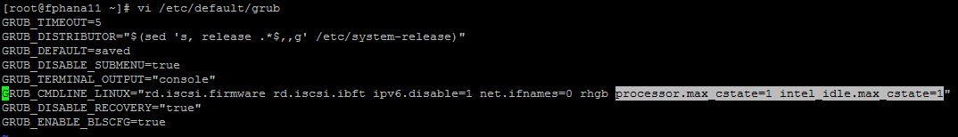
3. Update the GRUB2 configuration file:
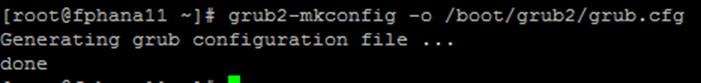
4. Increase kernel.pid_max -> Add the following line to /etc/sysctl.d/sap.conf (create the file if it doesn't already exist): kernel.pid_max=4194304
Perform reboot of the system to effect the GRUB update.
Install Cisco VIC Drivers
To download the Cisco UCS Drivers ISO bundle, which contains most Cisco UCS Virtual Interface Card drivers, follow these steps:
1. In a web browser, navigate to http://www.cisco.com. Click Software Downloads.
2. In the product selector, Browse all On the left under Downloads Home, click Servers - Unified Computing.
3. If prompted, enter your Cisco.com username and password to log in.
![]() You must be signed in to download Cisco Unified Computing System (Cisco UCS) drivers.
You must be signed in to download Cisco Unified Computing System (Cisco UCS) drivers.
4. Respective Cisco UCS server drivers are available under Cisco UCS B-Series Blade Server Software and Cisco UCS C-Series Rack-Mount UCS-Managed Server Software.
5. Click UCS B-Series Blade Server Software.
6. Click Unified Computing System (UCS) Drivers.
![]() The latest release version is selected by default. This document is built on Version 4.0(4g).
The latest release version is selected by default. This document is built on Version 4.0(4g).
7. Click 4.0(4d) Version.
8. Download ISO image of Cisco UCS-related drivers ucs-bxxx-drivers-linux.4.0.4g.
9. Choose your download method and follow the prompts to complete your driver download.
10. Browse the downloaded drivers iso -> ucs-bxxx-drivers-linux.4.0.4g\ Storage\Cisco\VIC\RHEL\RHEL8.0 and copy kmod-fnic-2.0.0.48-94.0.rhel8u0.x86_64 to also /opt of the HANA node
11. Update the fnic driver:
rpm -ivh /opt/kmod- fnic-2.0.0.48-94.0.rhel8u0.x86_64
12. Browse the downloaded drivers iso -> ucs-bxxx-drivers-linux.4.0.4g\Network\Cisco\VIC\RHEL\RHEL8.0 and copy kmod-enic-3.2.210.24-738.20.rhel8u0.x86_64 to /opt of the HANA node
13. Update the enic driver:
rpm -ivh /opt/kmod-enic-3.2.210.24-738.20.rhel8u0.x86_64
Synchronize Domain Information
To be able to mount the volumes inside the HANA nodes, the v4-id-domain information of NFS enabled hana-svm providing the HANA persistence access should tally with domain information in /etc/idmapd.conf of the HANA nodes.
On the NetApp command line fetch the information about the configured v4 domain as shown below:
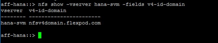
Make sure the same is updated in the ‘Domain’ filed on /etc/idmapd.conf file of HANA node.
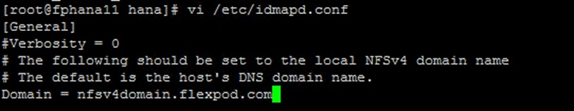
SAP HANA Node OS Preparation – SLES for SAP 15 SP1
This section explains the SLES for SAP 15 SP1installation and configuration.
Base OS Installation
To install the OS, follow these steps:
![]() The following steps show the SLES 15 for SAP SP1 installation procedure. Make sure you have the SLES 15 for SAP SP1 DVD.
The following steps show the SLES 15 for SAP SP1 installation procedure. Make sure you have the SLES 15 for SAP SP1 DVD.
1. Refer to the 2578899 - SUSE Linux Enterprise Server 15: Installation Note for installation instructions.
2. On the UCSM page, Servers -> Service Profiles -> root -> Sub-Organizations -> T01-HANA – Right-click singlehost-suse1 and select KVM console.
3. After the KVM console is launched, click Boot Server.
4. Choose Virtual Media > Activate Virtual Devices.
a. For Unencrypted Virtual Media Session, select Accept this Session and then click Apply.
b. Click Virtual Media and choose Map CD/DVD.
c. Click Browse to navigate to the ISO media location. Select SLE-15-SP1-Installer-DVD-x86_64-GM-DVD1.iso. Click Open.
d. Click Map Device.
5. At server boot time, during the check the of VIC FC boot driver version, it recognizes the NetApp iSCSI target via available paths per VIC. This verifies the server to storage connectivity.
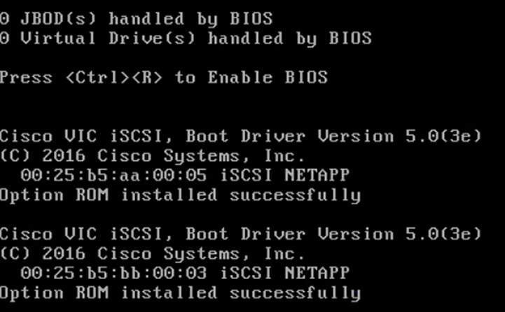
6. The System will automatically boot from the ISO image. Scroll down on the selection menu to Installation option and press Tab to key in the boot option ip=ibft. Click Return.
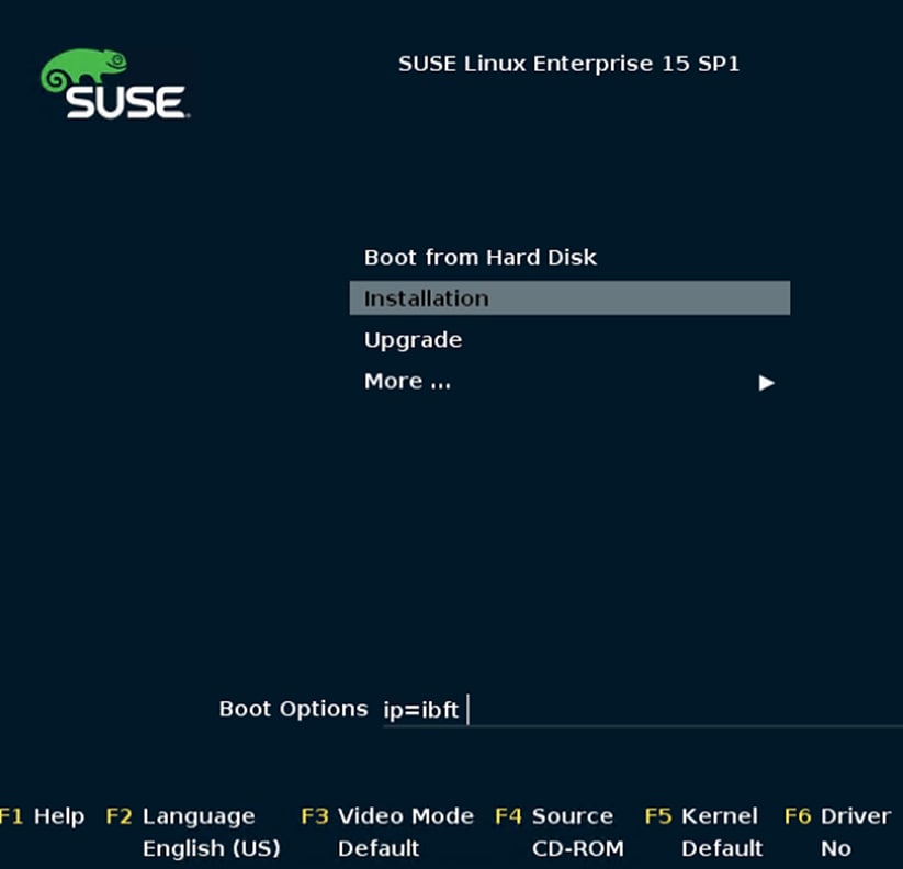
7. On the first “Language, Keyboard and License Agreement” page, select the Language of choice and Keyboard Layout. Select “SUSE Linux Enterprise Server for SAP Applications 15 SP1” for Product to Install and click Next.
8. SUSE Linux Enterprise Server for SAP Applications 15 SP1 License Agreement – Select “I Agree to the License Terms” . Click Next.
9. Disk Activation – Click Configure iSCSI Disks.
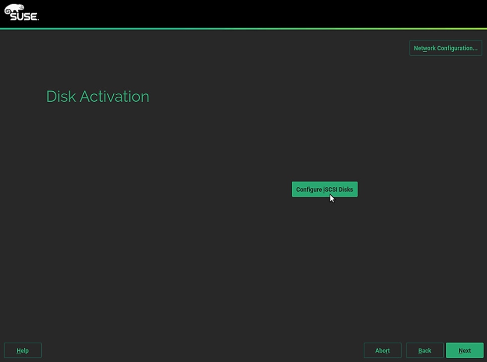
10. On the iSCSI Initiator tab, ensure the automatically selected Initiator Name is correct; if it isn’t, update the Initiator Name defined in the service profile.
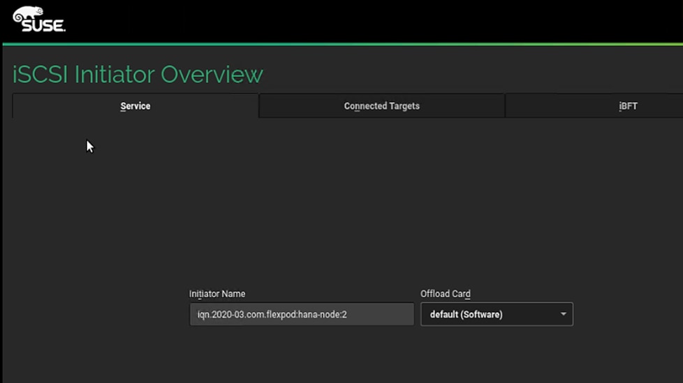
11. Click the Connected Targets tab, verify the interface can login to the available targets.
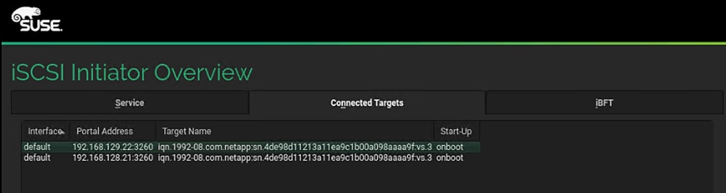
12. Make sure the Start-Up is set to onboot. Click OK.
13. Click Next.
14. System Probing – Select No for the prompt to activate multipath. You will activate the multipath post installation.
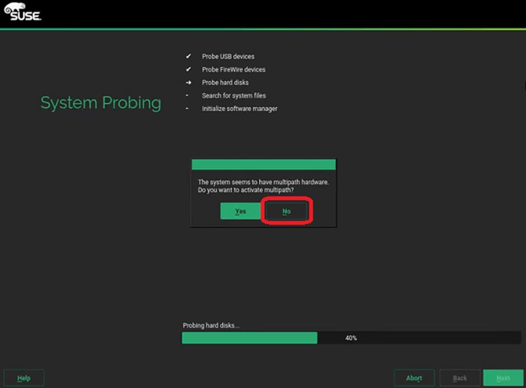
15. Registration – Select Skip Registration. You will register the system post installation. Click OK for the Warming.
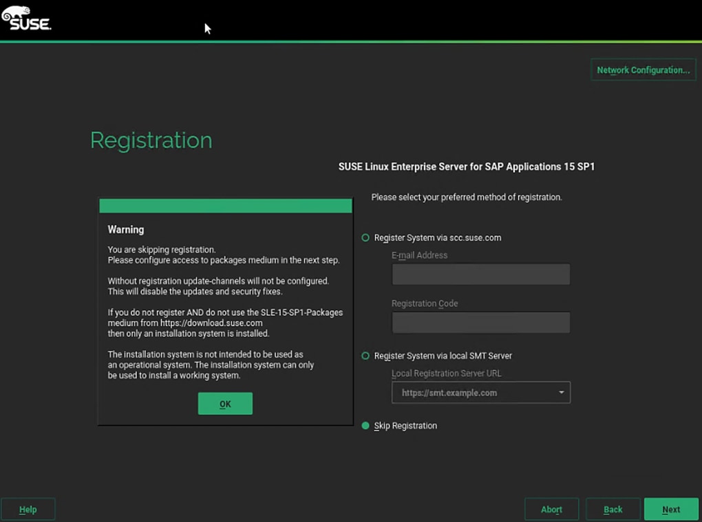
16. Add On Product: Select “I would like to install an additional Add On Product. And select DVD as the source. lick Next.
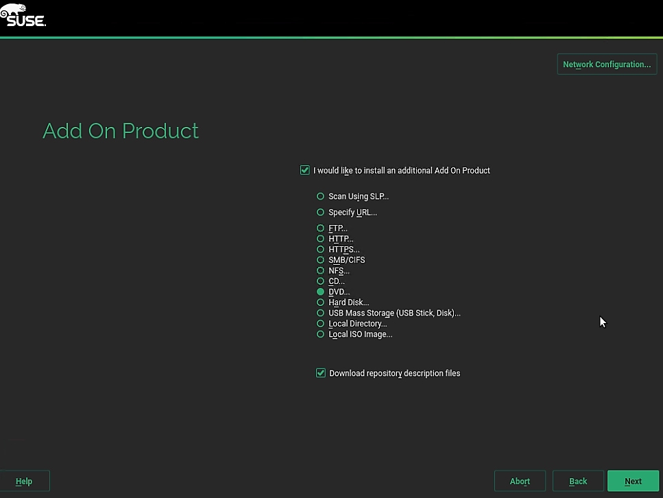
17. At this stage, unmap the currently mapped Installer DVD1 drive. Map the SLE-15-SP1-Packages-x86_64-GM-DVD1.iso Click Next.
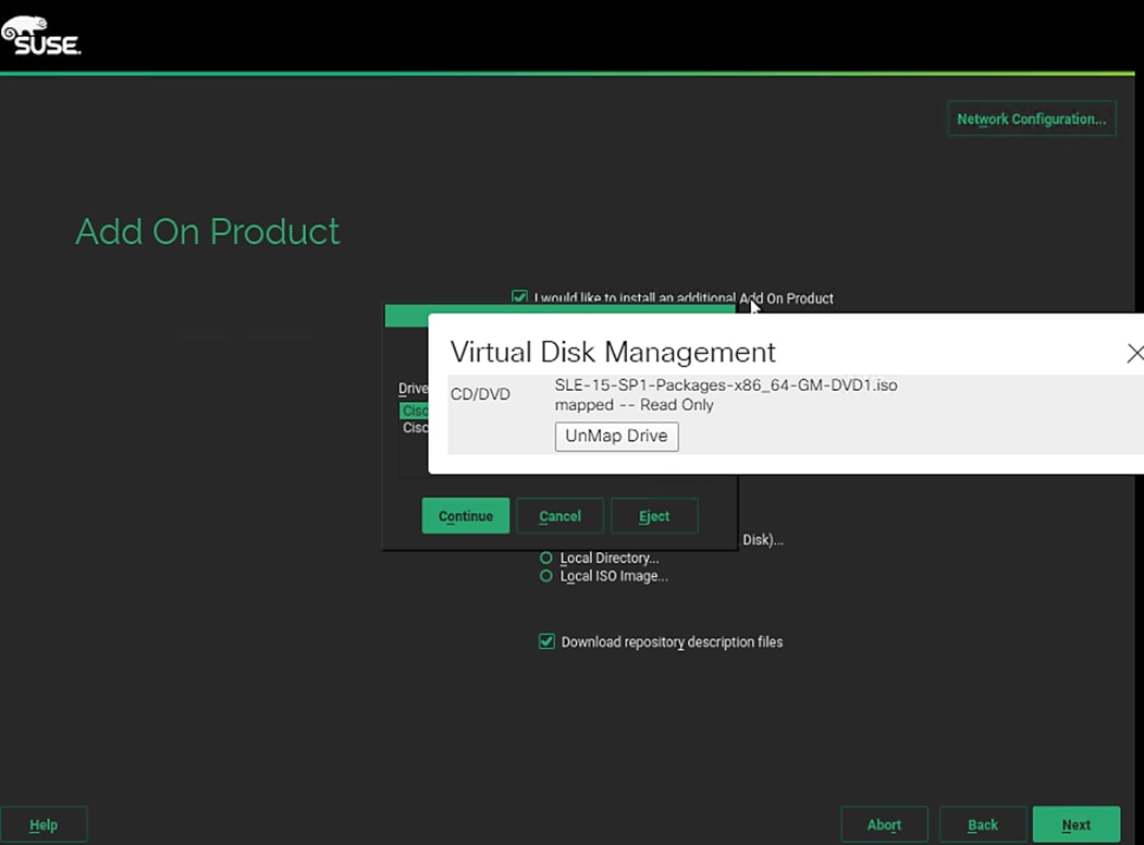
18. Extension and Module Selection - Select as appropriate. Click Next.
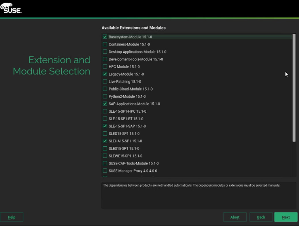
19. Click Next on the Add-On Product Installation page.
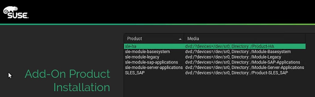
20. System Role – Keep the default selection of SLES for SAP Applications.
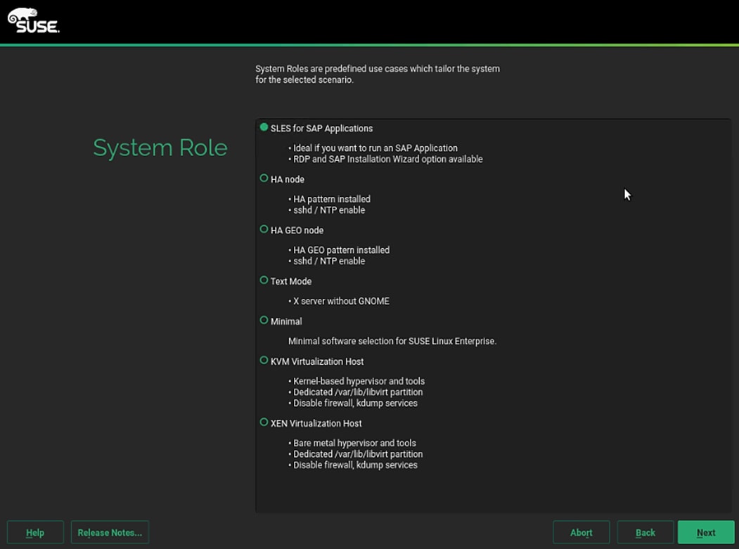
21. Choose Operating System Edition – Unselect both options. Click Next.
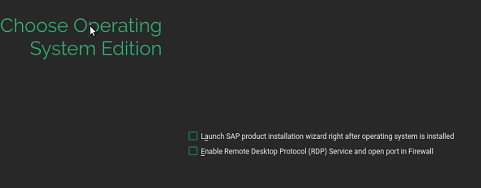
22. Suggested Partitioning – Click Expert Partitioner and Select Start with Existing Partitions.
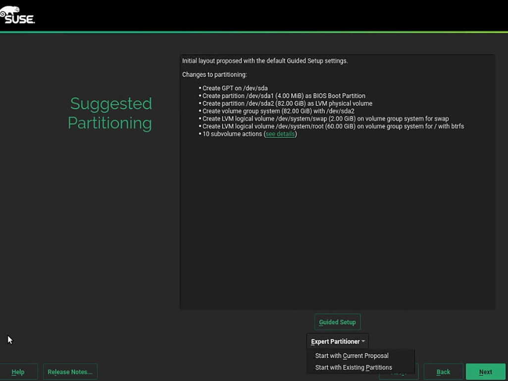
23. Expert Partitioner – Select one of the iSCSi NetApp devices listed.
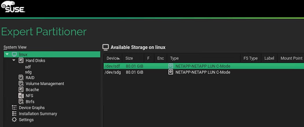
24. On the Partition tab, select Add Partition.
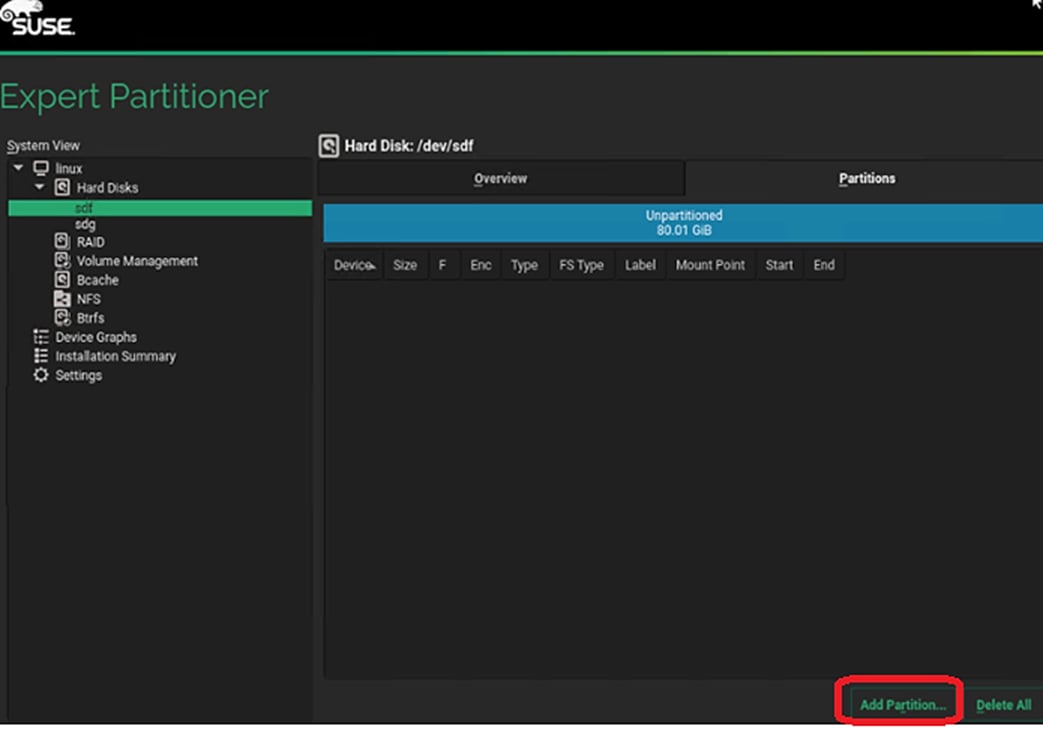
25. Create a 100 MiB size partition for BIOS_Boot volume purpose.
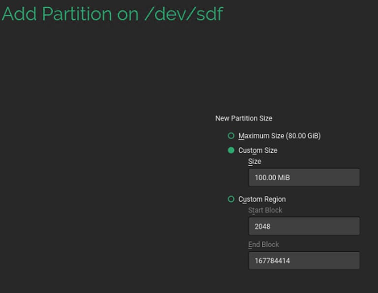
26. Select Raw Volume (unformatted) for the Role.
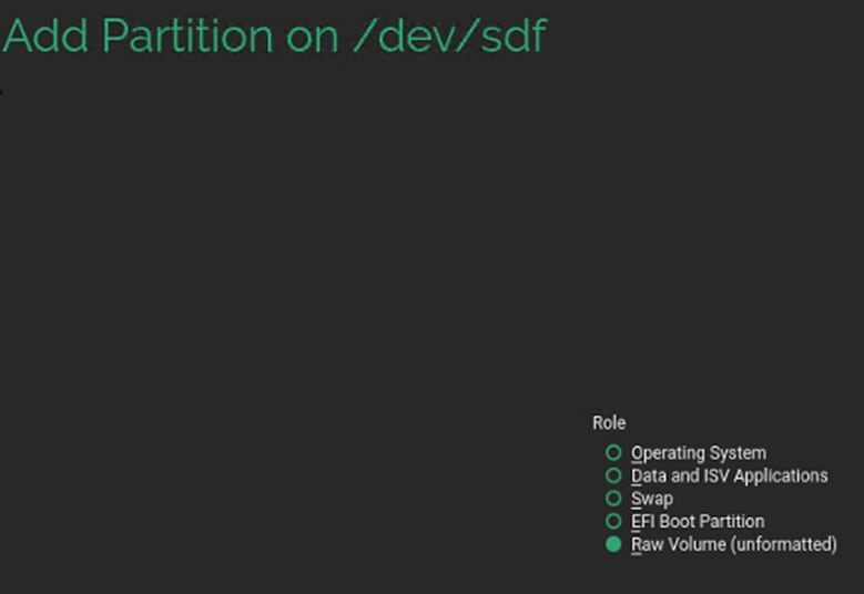
27. Select BIOS Boot Partition under Partition ID and leave the rest with default selections.
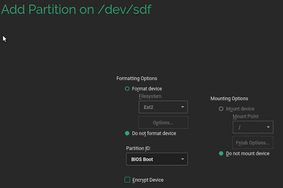
28. Add New Partition with Maximum Size, using up the rest of the space available on drive. Click Next.
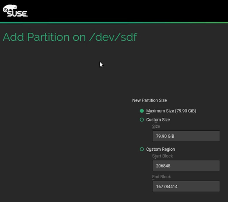
29. Select Operating System Role and click Next.
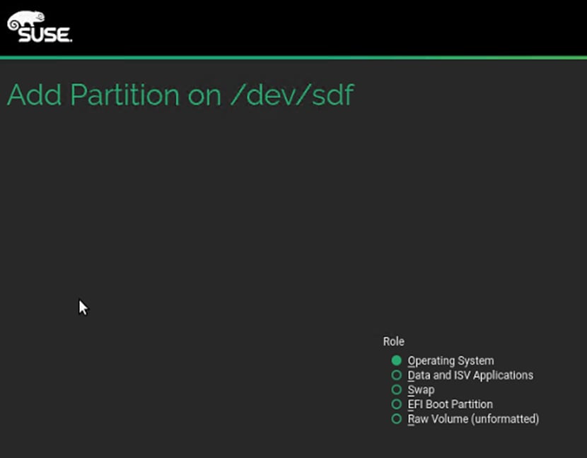
30. Select Filesystem. Click Next. For the boot device there is no restriction on the filesystem that you can choose.
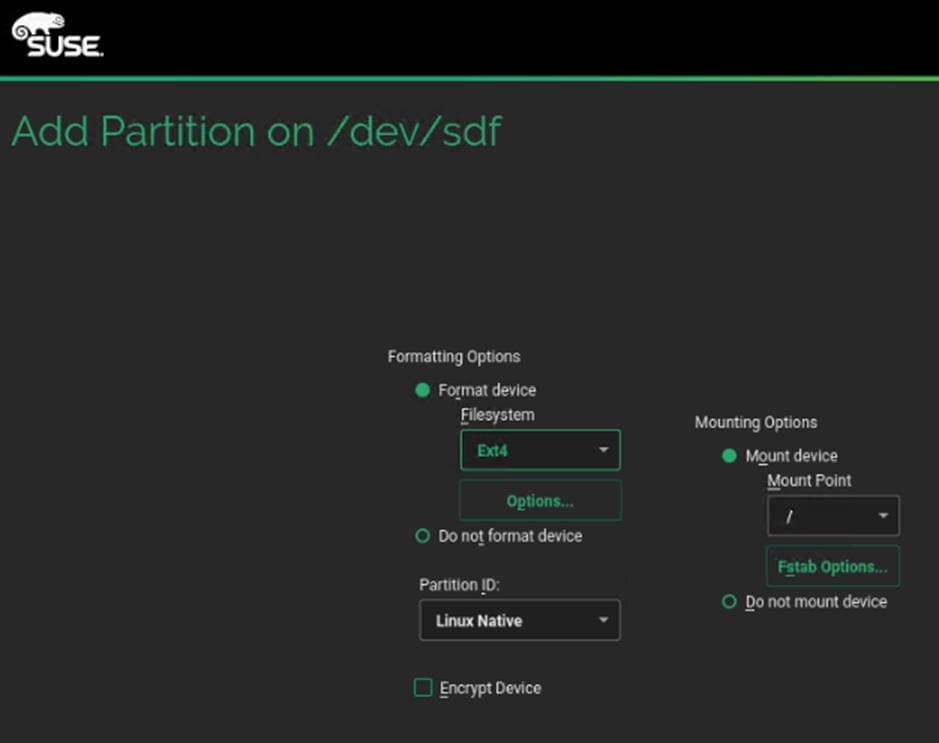
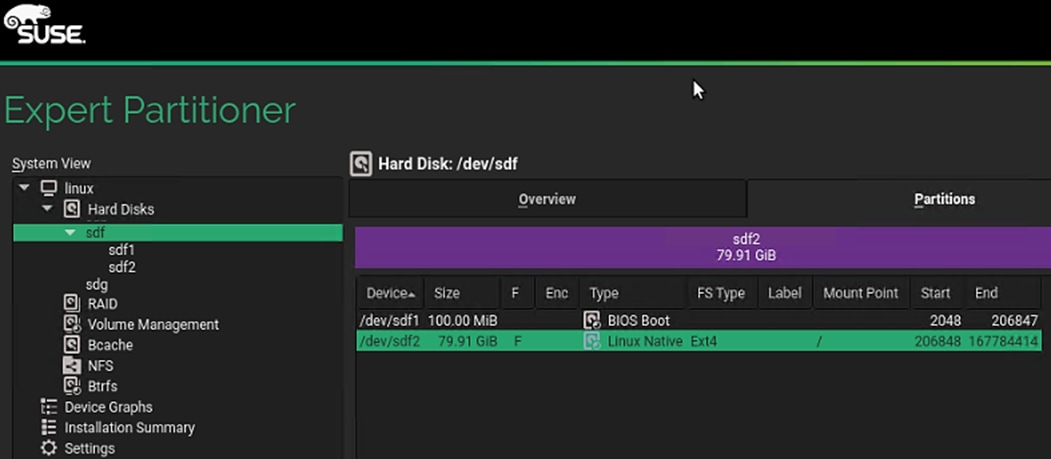
31. Click Accept. Click Yes for the warning, to continue. You will create the swap file later.
32. Suggested partitioning – Click Next.
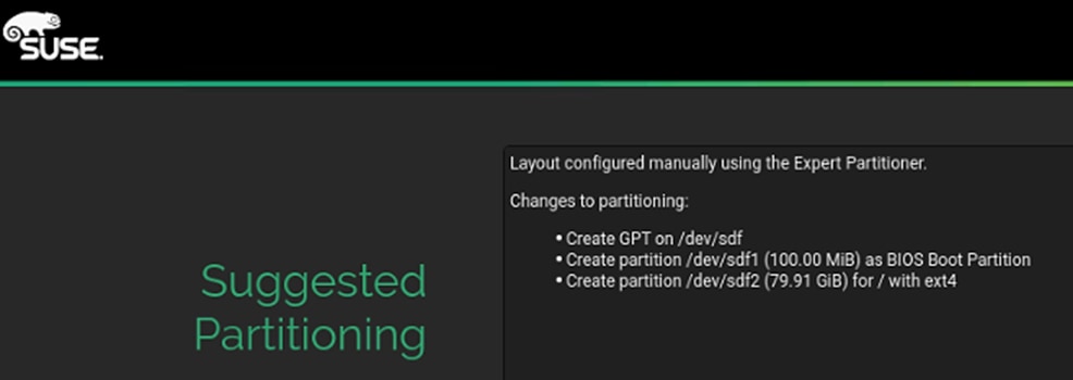
33. Clock and Time Zone – choose the appropriate time zone and select Hardware clock set to UTC.
34. Password for the System Administrator “root” – Key in appropriate password. Click Next.
35. On the Installation Settings screen, review the default information. Disable Firewall. Disable Kdump. Set Default systemd target set to Text mode.
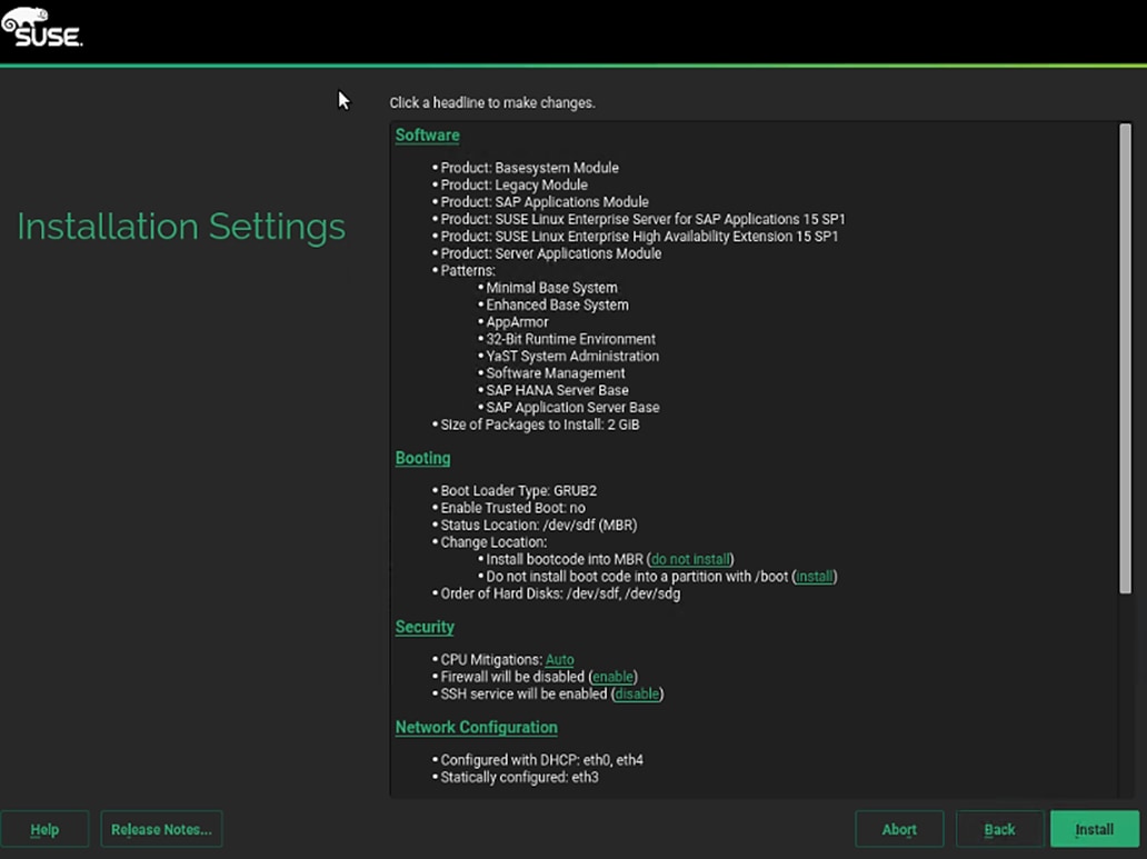
36. Click Install and select Install again for the subsequent ‘Confirm Installation’ prompt. The installation is started and you can monitor the status.
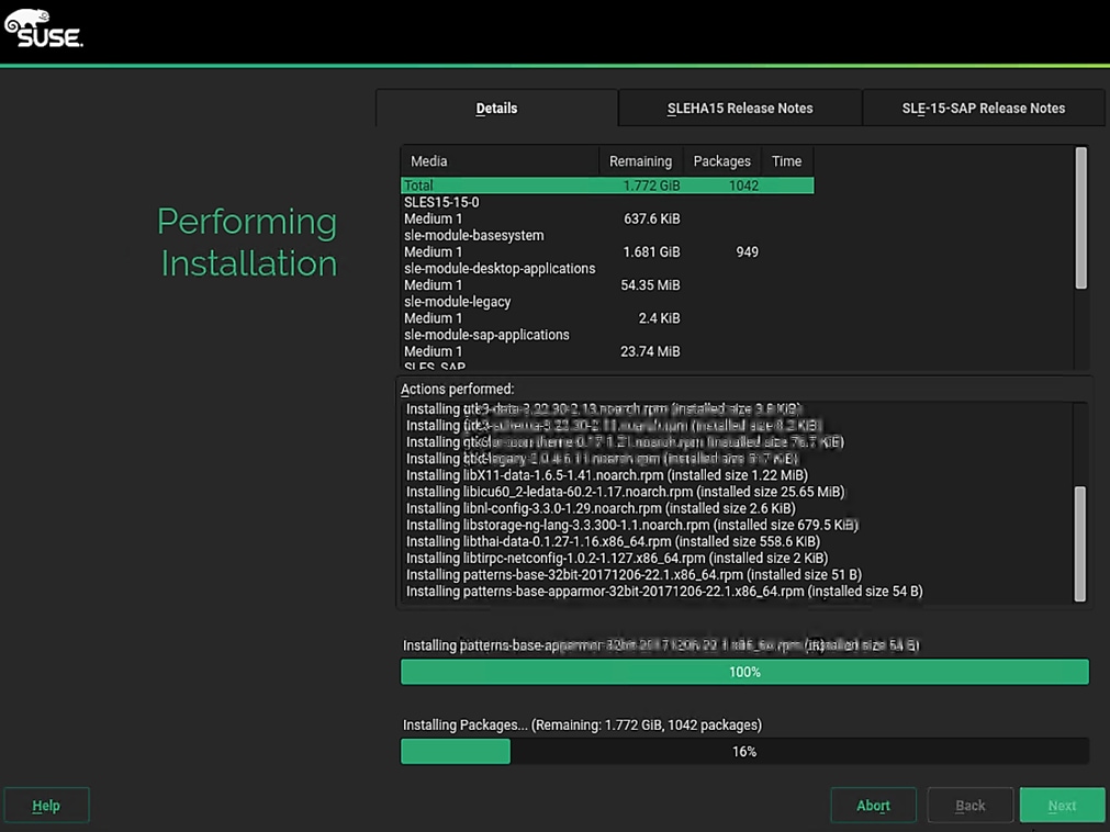
37. When prompted during the installation process, re-map installation DVD1.
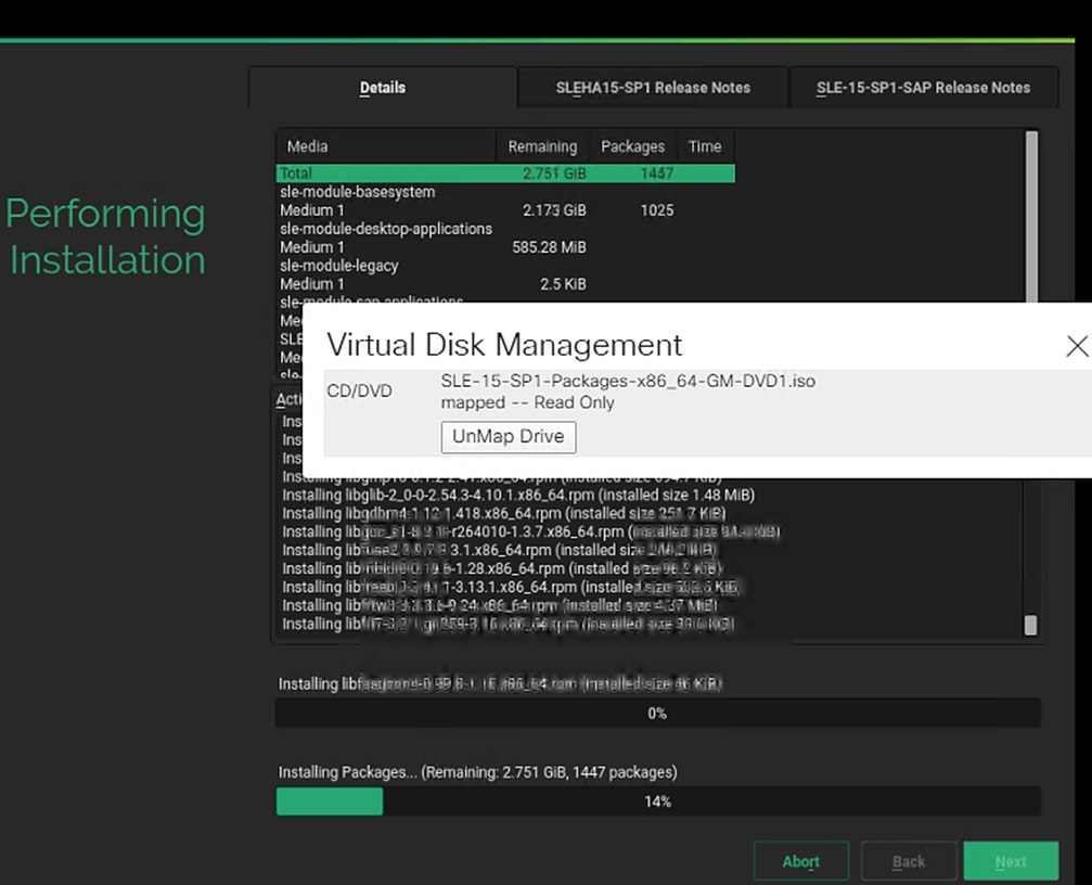
38. After the installation is complete, a reboot alert appears. The system will reboot and boot from disk on startup. Login using the root.
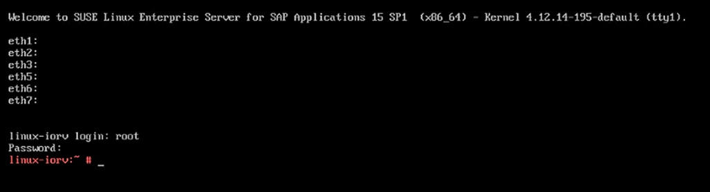
Post Installation Steps
Configure the Network
As part of the post-install configuration, you will define the hostname, network configuration, kernel/packages update, and tuning as per the SAP Notes recommendations.
To configure the network, follow these steps:
1. Configure the hostname and disable IPV6.
#yast2
2. System > Network Settings and select Run > Alt+s to select Hostname/DNS tab.
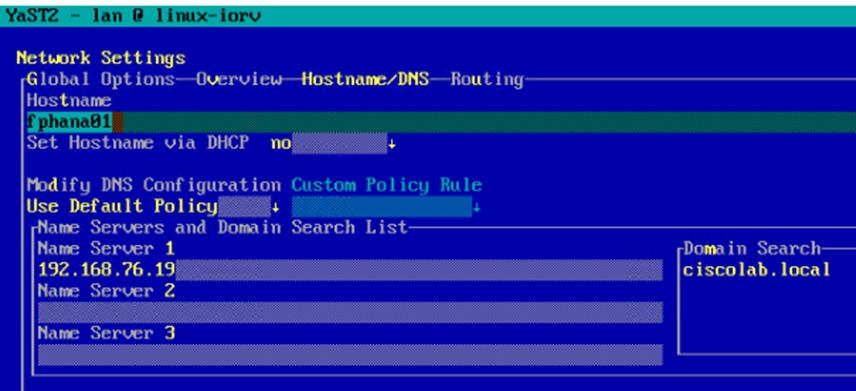
3. Input the hostname. Also, key in DNS server address of your network for resolution, if any and select Alt+o.
4. On the Global Options tab with Alt+g, you can choose to disable IPV6, by unselecting the Enable IPV6 option as shown in the figure below. Changing the IPV6 setting requires a reboot to effect the changes.
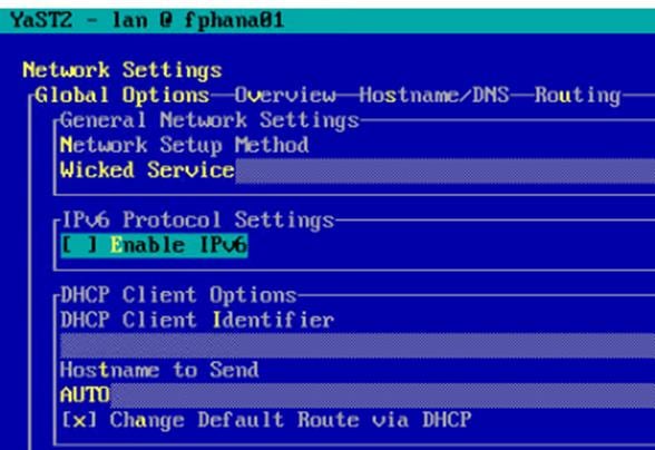
5. Select Alt+o to save the Network Configuration. Select Alt+q to quit the YaST Control center.
6. Host networking configuration:
a. The vNIC to MAC address mapping information for a host can be obtained from the network tab of that host’s Service Profile.
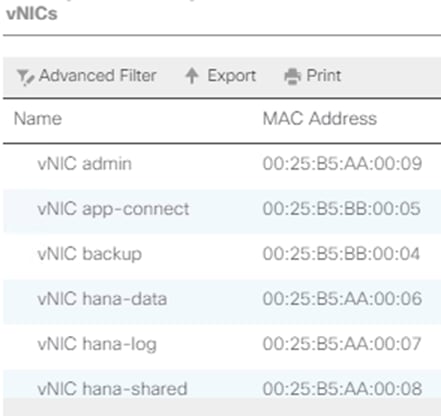
b. At the host OS level, the Ethernet interface to MAC address mapping can be ascertained with the ‘ip address’ command.
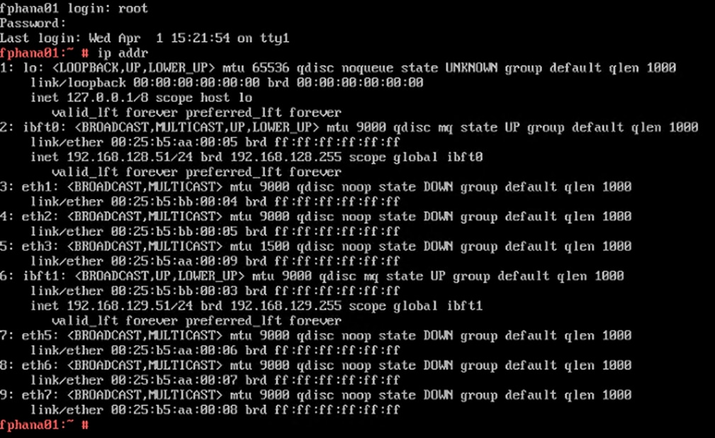
![]() iSCSI vNICs appear as ibft0 and ibft1 with their IP addresses assigned. Their interface configuration files ifcfg-eth2 and ifcfg-eth6 files are found in the /etc/sysconfig/network directory. We will be needing to create and configure the rest of the interface config files.
iSCSI vNICs appear as ibft0 and ibft1 with their IP addresses assigned. Their interface configuration files ifcfg-eth2 and ifcfg-eth6 files are found in the /etc/sysconfig/network directory. We will be needing to create and configure the rest of the interface config files.
c. Co-relating the outputs in step a and b above, we are able to determine the right IP address/network that need to should be assigned to the Ethernet interface. For the same an IP addressing scheme cheat sheet, as below, can be quite handy.

d. Assign the IP address and subnet mask for the ethernet interfaces based on the al the information we have so far.
#cd /etc/sysconfig/network
#vi ifcfg-eth1
BOOTPROTO='static'
BROADCAST=''
ETHTOOL_OPTIONS=''
IPADDR='192.168.224.201'
MTU='9000'
NAME='backup'
NETMASK='255.255.255.0'
NETWORK=''
REMOTE_IPADDR=''
STARTMODE=auto
#vi ifcfg-eth2
BOOTPROTO='static'
BROADCAST=''
ETHTOOL_OPTIONS=''
IPADDR='192.168.223.201'
MTU='9000'
NAME='app-connect'
NETMASK='255.255.255.0'
NETWORK=''
REMOTE_IPADDR=''
STARTMODE=auto
#vi ifcfg-eth3
BOOTPROTO='static'
BROADCAST=''
ETHTOOL_OPTIONS=''
IPADDR='192.168.76.201'
MTU='1500'
NAME='admin'
NETMASK='255.255.255.0'
NETWORK=''
REMOTE_IPADDR=''
STARTMODE=auto
#vi ifcfg-eth5
BOOTPROTO='static'
BROADCAST=''
ETHTOOL_OPTIONS=''
IPADDR='192.168.201.201'
MTU='9000'
NAME='hana-data'
NETMASK='255.255.255.0'
NETWORK=''
REMOTE_IPADDR=''
STARTMODE=auto
#vi ifcfg-eth6
BOOTPROTO='static'
BROADCAST=''
ETHTOOL_OPTIONS=''
IPADDR='192.168.228.210'
MTU='9000'
NAME='hana-log'
NETMASK='255.255.255.0'
NETWORK=''
REMOTE_IPADDR=''
STARTMODE=auto
#vi ifcfg-eth7
BOOTPROTO='static'
BROADCAST=''
ETHTOOL_OPTIONS=''
IPADDR='192.168.130.201'
MTU='9000'
NAME='hanashared'
NETMASK='255.255.255.0'
NETWORK=''
REMOTE_IPADDR=''
STARTMODE=auto
e. Add the default gateway.
#cd /etc/sysconfig/network
# vi routes
default <<var_mgmt_gateway_ip>> - -
f. Perform a network service restart to effect the updates relating to IP settings. With admin IP configuration, you would be able to ssh to the host.
# service network restart
g. Update the /etc/hosts with IP address of all networks and their alias hostnames:
fphana01:~ # vi /etc/hosts
#
# hosts This file describes a number of hostname-to-address
# mappings for the TCP/IP subsystem. It is mostly
# used at boot time, when no name servers are running.
# On small systems, this file can be used instead of a
# "named" name server.
# Syntax:
#
# IP-Address Full-Qualified-Hostname Short-Hostname
#
127.0.0.1 localhost
# special IPv6 addresses
::1 localhost ipv6-localhost ipv6-loopback
fe00::0 ipv6-localnet
ff00::0 ipv6-mcastprefix
ff02::1 ipv6-allnodes
ff02::2 ipv6-allrouters
ff02::3 ipv6-allhosts
#
## AppServer Network
#
192.168.223.201 fphana01a.ciscolab.local fphana01a
#
## Admin Network
#
192.168.76.201 fphana01.ciscolab.local fphana01
#
## Backup Network
#
192.168.224.201 fphana01b.ciscolab.local fphana01b
#
## HANA-data Network
#
192.168.201.201 fphana01d.ciscolab.local fphana01d
#
## HANA-log Network
#
192.168.228.201 fphana01l.ciscolab.local fphana01l
#
## HANA -shared Network
#
192.168.130.201 fphana01s.ciscolab.local fphana01s
#
h. Create SWAP partition.
#dd if=/dev/zero of=/swap_01 bs=1024 count=2097152
#mkswap /swap_01
#chown root:disk /swap_01
#chmod 600 /swap_01
#swapon /swap_01
i. Update the /etc/fstab with swap filesystem information by appending this line.
/swap_01 swap swap defaults 0 0
7. Set up a proxy service, so that the appliance can reach the Internet.
a. YaST2 – Key in the proxy server and port details. Select OK and then quit YaST to save the configuration.
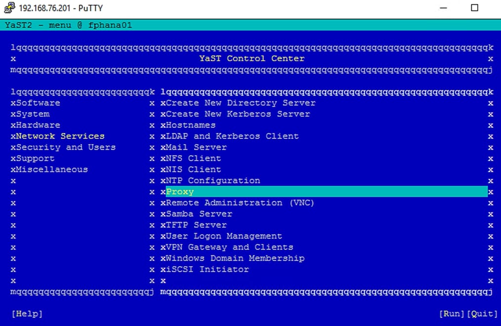
b. Select “Enable Proxy” > key in the <<proxy server IP address:port >> information and select “use same proxy for all Protocols” option.
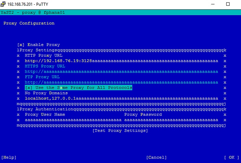
c. Test the Proxy Settings to make they are working.
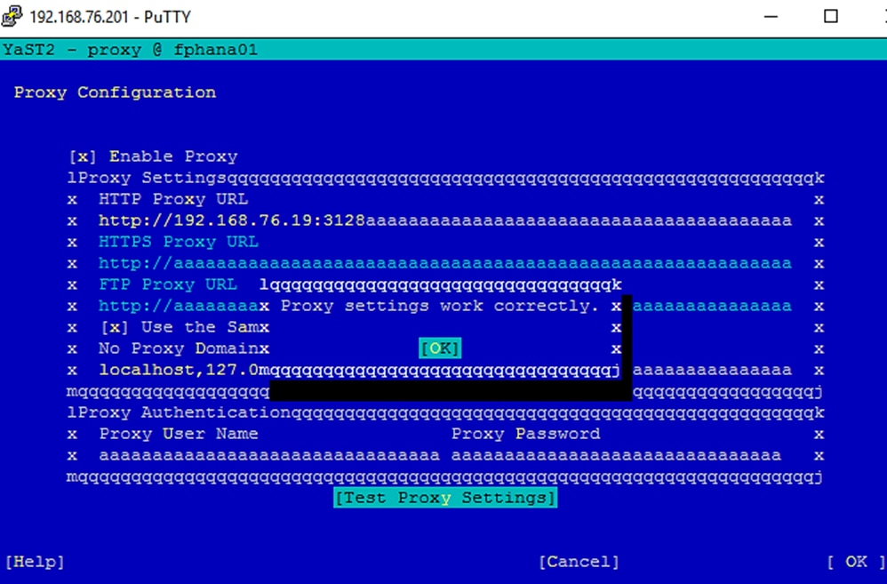
![]() Reboot the system to effect disabling ipv6 before going ahead with the registration step.
Reboot the system to effect disabling ipv6 before going ahead with the registration step.
Update the SLES System
To update the SLES system, follow these steps:
1. Register the system with SUSE to get the latest patches. The system must have access to the Internet to proceed with this step.
#SUSEConnect -r <<registration_code>>
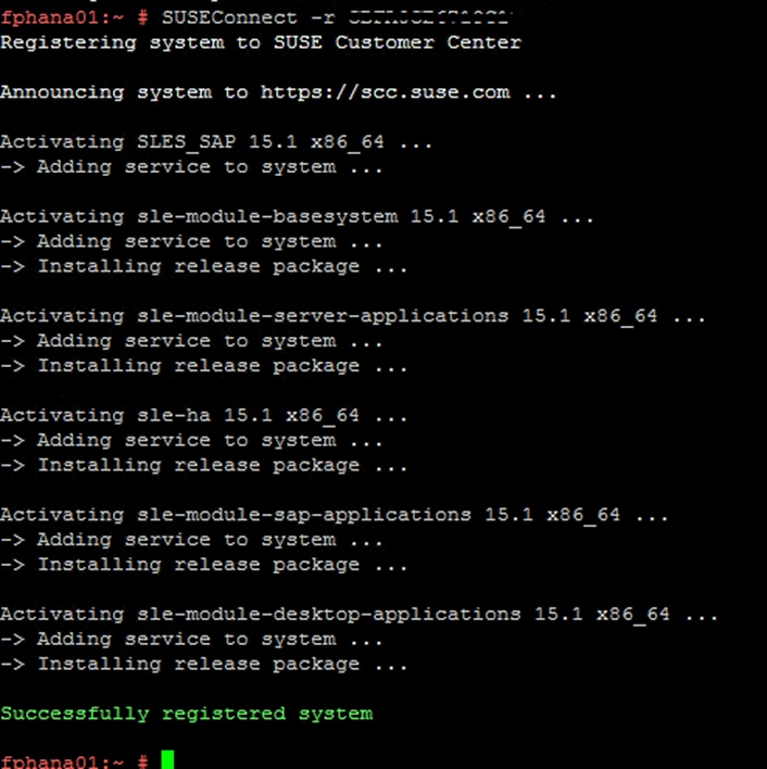
2. Update the system with the following command. Again, the system must have access to the Internet to proceed with this step.
#zypper update
3. Follow the on-screen instructions to complete the update process. Reboot the server, as suggested and log in to the system again.
Install Cisco VIC Drivers
To install the Cisco VIC drivers, follow these steps:
1. Update fnic and enic drivers:
a. Based on the serer type/model, processor version, OS release and version information download the Firmware bundle corresponding to the UCS Server firmware installed from the Cisco UCS Hardware and Software Compatibility site
b. Extract the rpm files of the fnic and enic drivers from the bundle over to the node.
fphana01:~ # cd /opt
fphana01:/opt # ll
total 3176
-rw-r--r-- 1 root root 1974804 Oct 7 22:21 cisco-enic-usnic-kmp-default-3.2.272.32_k4.12.14_195-738.37.x86_64.rpm
-rw-r--r-- 1 root root 1271784 Oct 7 22:21 cisco-fnic-kmp-default-2.0.0.50-100.0.x86_64.rpm
fphana01:/opt # rpm -ivh cisco-fnic-kmp-default-2.0.0.50-100.0.x86_64.rpm
Preparing... ################################# [100%]
Updating / installing...
1:cisco-fnic-kmp-default-2.0.0.50_k################################# [100%]
fphana01:/opt # rpm -ivh cisco-enic-usnic-kmp-default-3.2.272.32_k4.12.14_195-738.37.x86_64.rpm
Preparing... ################################# [100%]
Updating / installing...
1:cisco-enic-usnic-kmp-default-3.2.################################# [100%]
Creating initrd: /boot/initrd-4.12.14-195-default
dracut: Executing: /usr/bin/dracut --logfile /var/log/YaST2/mkinitrd.log --force /boot/initrd-4.12.14-195-default 4.12.14-195-default
dracut: dracut module 'dmraid' will not be installed, because command 'dmraid' could not be found!
dracut: dracut module 'dmraid' will not be installed, because command 'dmraid' could not be found!
dracut: *** Including module: bash ***
dracut: *** Including module: systemd ***
dracut: *** Including module: warpclock ***
dracut: *** Including module: systemd-initrd ***
dracut: *** Including module: i18n ***
dracut: *** Including module: network ***
dracut: *** Including module: drm ***
dracut: *** Including module: plymouth ***
dracut: *** Including module: kernel-modules ***
dracut: *** Including module: kernel-network-modules ***
dracut: *** Including module: iscsi ***
dracut: *** Including module: rootfs-block ***
dracut: *** Including module: suse-btrfs ***
dracut: *** Including module: suse-xfs ***
dracut: *** Including module: terminfo ***
dracut: *** Including module: udev-rules ***
dracut: Skipping udev rule: 40-redhat.rules
dracut: Skipping udev rule: 50-firmware.rules
dracut: Skipping udev rule: 50-udev.rules
dracut: Skipping udev rule: 91-permissions.rules
dracut: Skipping udev rule: 80-drivers-modprobe.rules
dracut: *** Including module: dracut-systemd ***
dracut: *** Including module: haveged ***
dracut: *** Including module: usrmount ***
dracut: *** Including module: base ***
dracut: *** Including module: fs-lib ***
dracut: *** Including module: shutdown ***
dracut: *** Including module: suse ***
dracut: *** Including modules done ***
dracut: *** Installing kernel module dependencies and firmware ***
dracut: *** Installing kernel module dependencies and firmware done ***
dracut: *** Resolving executable dependencies ***
dracut: *** Resolving executable dependencies done***
dracut: *** Hardlinking files ***
dracut: *** Hardlinking files done ***
dracut: *** Stripping files ***
dracut: *** Stripping files done ***
dracut: *** Generating early-microcode cpio image ***
dracut: *** Constructing GenuineIntel.bin ****
dracut: *** Store current command line parameters ***
dracut: Stored kernel commandline:
dracut: rd.iscsi.ibft=1 rd.iscsi.firmware=1
dracut: root=UUID=c3e826ba-bd1f-461b-877e-9900cc0dbd52 rootfstype=ext4 rootflags=rw,relatime,stripe=16,data=ordered
dracut: *** Creating image file '/boot/initrd-4.12.14-195-default' ***
dracut: *** Creating initramfs image file '/boot/initrd-4.12.14-195-default' done ***
Creating initrd: /boot/initrd-4.12.14-197.37-default
dracut: Executing: /usr/bin/dracut --logfile /var/log/YaST2/mkinitrd.log --force /boot/initrd-4.12.14-197.37-default 4.12.14-197.37-default
dracut: dracut module 'dmraid' will not be installed, because command 'dmraid' could not be found!
dracut: dracut module 'dmraid' will not be installed, because command 'dmraid' could not be found!
dracut: *** Including module: bash ***
dracut: *** Including module: systemd ***
dracut: *** Including module: warpclock ***
dracut: *** Including module: systemd-initrd ***
dracut: *** Including module: i18n ***
dracut: *** Including module: network ***
dracut: *** Including module: drm ***
dracut: *** Including module: plymouth ***
dracut: *** Including module: kernel-modules ***
dracut: *** Including module: kernel-network-modules ***
dracut: *** Including module: iscsi ***
dracut: *** Including module: rootfs-block ***
dracut: *** Including module: suse-btrfs ***
dracut: *** Including module: suse-xfs ***
dracut: *** Including module: terminfo ***
dracut: *** Including module: udev-rules ***
dracut: Skipping udev rule: 40-redhat.rules
dracut: Skipping udev rule: 50-firmware.rules
dracut: Skipping udev rule: 50-udev.rules
dracut: Skipping udev rule: 91-permissions.rules
dracut: Skipping udev rule: 80-drivers-modprobe.rules
dracut: *** Including module: dracut-systemd ***
dracut: *** Including module: haveged ***
dracut: *** Including module: usrmount ***
dracut: *** Including module: base ***
dracut: *** Including module: fs-lib ***
dracut: *** Including module: shutdown ***
dracut: *** Including module: suse ***
dracut: *** Including modules done ***
dracut: *** Installing kernel module dependencies and firmware ***
dracut: *** Installing kernel module dependencies and firmware done ***
dracut: *** Resolving executable dependencies ***
dracut: *** Resolving executable dependencies done***
dracut: *** Hardlinking files ***
dracut: *** Hardlinking files done ***
dracut: *** Stripping files ***
dracut: *** Stripping files done ***
dracut: *** Generating early-microcode cpio image ***
dracut: *** Constructing GenuineIntel.bin ****
dracut: *** Store current command line parameters ***
dracut: Stored kernel commandline:
dracut: rd.iscsi.ibft=1 rd.iscsi.firmware=1
dracut: root=UUID=c3e826ba-bd1f-461b-877e-9900cc0dbd52 rootfstype=ext4 rootflags=rw,relatime,stripe=16,data=ordered
dracut: *** Creating image file '/boot/initrd-4.12.14-197.37-default' ***
dracut: *** Creating initramfs image file '/boot/initrd-4.12.14-197.37-default' done ***
fphana01:/opt #***
fphana02:/opt #
2. Multipath configuration:
![]() We disabled multipath during install time. It is recommended to install OS using a single path referencing the iSCSi device and enable the multipath configuration post OS installation and zypper update.
We disabled multipath during install time. It is recommended to install OS using a single path referencing the iSCSi device and enable the multipath configuration post OS installation and zypper update.
a. At first check with multipath – ll may not return any result.
b. Enable and start the multipath daemon and verify it active status.
fphana01:~# multipath -ll
fphana01:~# systemctl enable multipathd
Created symlink /etc/systemd/system/sysinit.target.wants/multipathd.service → /usr/lib/systemd/system/multipathd.service.
Created symlink /etc/systemd/system/sockets.target.wants/multipathd.socket → /usr/lib/systemd/system/multipathd.socket.
fphana01:~# systemctl start multipathd
fphana01:~# systemctl status multipathd
● multipathd.service - Device-Mapper Multipath Device Controller
Loaded: loaded (/usr/lib/systemd/system/multipathd.service; enabled; vendor preset: disabled)
Active: active (running) since Mon 2020-04-06 07:41:12 PDT; 10s ago
Process: 31560 ExecStartPre=/sbin/modprobe -a scsi_dh_alua scsi_dh_emc scsi_dh_rdac dm-multipath (code=exited, status=0/SUCCESS)
Main PID: 31561 (multipathd)
Status: "up"
Tasks: 7
CGroup: /system.slice/multipathd.service
└─31561 /sbin/multipathd -d -s
Apr 06 07:41:11 fphana01 systemd[1]: Starting Device-Mapper Multipath Device Controller...
Apr 06 07:41:11 fphana01 multipathd[31561]: --------start up--------
Apr 06 07:41:11 fphana01 multipathd[31561]: read /etc/multipath.conf
Apr 06 07:41:11 fphana01 multipathd[31561]: path checkers start up
Apr 06 07:41:12 fphana01 multipathd[31561]: 35000c500b7492797: load table [0 585937500 multipath 0 0 1 1 service-time 0 1 1 8:0 1]
Apr 06 07:41:12 fphana01 multipathd[31561]: 35000c500b749ac53: load table [0 585937500 multipath 0 0 1 1 service-time 0 1 1 8:16 1]
Apr 06 07:41:12 fphana01 multipathd[31561]: 3600a098038303868365d4f626c384876: ignoring map
Apr 06 07:41:12 fphana01 systemd[1]: Started Device-Mapper Multipath Device Controller.
c. Check with iscsiadm commands to check for iscsi logins. If some paths are missing, discover the target and make sure the initiators are logged in to all available ports. The targets that the indictors report error are one that aren’t allowed by the contract we have that disallows cross connects for iSCSI connections.
fphana01:~# iscsiadm -m session
tcp: [1] 192.168.128.21:3260,1027 iqn.1992-08.com.netapp:sn.4de98d11213a11ea9c1b00a098aaaa9f:vs.3 (non-flash)
fphana01:~# iscsiadm -m discovery -t st -p 192.168.128.21
192.168.128.21:3260,1027 iqn.1992-08.com.netapp:sn.4de98d11213a11ea9c1b00a098aaaa9f:vs.3
192.168.129.22:3260,1030 iqn.1992-08.com.netapp:sn.4de98d11213a11ea9c1b00a098aaaa9f:vs.3
192.168.128.22:3260,1029 iqn.1992-08.com.netapp:sn.4de98d11213a11ea9c1b00a098aaaa9f:vs.3
192.168.129.21:3260,1028 iqn.1992-08.com.netapp:sn.4de98d11213a11ea9c1b00a098aaaa9f:vs.3
fphana01:~# iscsiadm -m node --loginall=all
iscsiadm: default: 1 session requested, but 1 already present.
Logging in to [iface: default, target: iqn.1992-08.com.netapp:sn.4de98d11213a11ea9c1b00a098aaaa9f:vs.3, portal: 192.168.129.22,3260]
Logging in to [iface: default, target: iqn.1992-08.com.netapp:sn.4de98d11213a11ea9c1b00a098aaaa9f:vs.3, portal: 192.168.129.21,3260]
iscsiadm: default: 1 session requested, but 1 already present.
Logging in to [iface: default, target: iqn.1992-08.com.netapp:sn.4de98d11213a11ea9c1b00a098aaaa9f:vs.3, portal: 192.168.129.22,3260]
Logging in to [iface: default, target: iqn.1992-08.com.netapp:sn.4de98d11213a11ea9c1b00a098aaaa9f:vs.3, portal: 192.168.128.22,3260]
Login to [iface: default, target: iqn.1992-08.com.netapp:sn.4de98d11213a11ea9c1b00a098aaaa9f:vs.3, portal: 192.168.129.22,3260] successful.
iscsiadm: Could not login to [iface: default, target: iqn.1992-08.com.netapp:sn.4de98d11213a11ea9c1b00a098aaaa9f:vs.3, portal: 192.168.129.21,3260].
iscsiadm: initiator reported error (8 - connection timed out)
iscsiadm: Could not login to [iface: default, target: iqn.1992-08.com.netapp:sn.4de98d11213a11ea9c1b00a098aaaa9f:vs.3, portal: 192.168.129.22,3260].
iscsiadm: initiator reported error (15 - session exists)
iscsiadm: Could not login to [iface: default, target: iqn.1992-08.com.netapp:sn.4de98d11213a11ea9c1b00a098aaaa9f:vs.3, portal: 192.168.128.22,3260].
iscsiadm: initiator reported error (8 - connection timed out)
iscsiadm: Could not log into all portals
d. Restart multipathd and Enable and start the multipath daemon and verify it active status.
fphana01:~ # systemctl restart multipathd
fphana01:~ # multipath -r
fphana01:~ # multipath -ll
3600a098038303868365d4f626c384876 dm-2 NETAPP,LUN C-Mode
size=80G features='3 queue_if_no_path pg_init_retries 50' hwhandler='1 alua' wp=rw
|-+- policy='service-time 0' prio=50 status=active
| `- 8:0:0:0 sdd 8:48 active ready running
`-+- policy='service-time 0' prio=10 status=enabled
`- 7:0:0:0 sdc 8:32 active ready running
e. Create a Dracut configuration file exclusively for multipath.
fphana01:~ # echo 'force_drivers+="dm_multipath dm_service_time"' >> /etc/dracut.conf.d/10-mp.conf
f. Rebuild the initrd ad reboot the system. The multipath configuration works for sure after the reboot, if not earlier.
fphana01:~ # dracut -f -a multipath
dracut: Executing: /usr/bin/dracut -f -a multipath
dracut: dracut module 'dmraid' will not be installed, because command 'dmraid' could not be found!
dracut: dracut module 'dmraid' will not be installed, because command 'dmraid' could not be found!
dracut: *** Including module: bash ***
dracut: *** Including module: systemd ***
dracut: *** Including module: warpclock ***
dracut: *** Including module: systemd-initrd ***
dracut: *** Including module: i18n ***
dracut: *** Including module: network ***
dracut: *** Including module: drm ***
dracut: *** Including module: plymouth ***
dracut: *** Including module: dm ***
dracut: Skipping udev rule: 64-device-mapper.rules
dracut: Skipping udev rule: 60-persistent-storage-dm.rules
dracut: Skipping udev rule: 55-dm.rules
dracut: *** Including module: kernel-modules ***
dracut: *** Including module: kernel-network-modules ***
dracut: *** Including module: multipath ***
dracut: Skipping udev rule: 40-multipath.rules
dracut: *** Including module: iscsi ***
dracut: *** Including module: rootfs-block ***
dracut: *** Including module: suse-btrfs ***
dracut: *** Including module: suse-xfs ***
dracut: *** Including module: terminfo ***
dracut: *** Including module: udev-rules ***
dracut: Skipping udev rule: 40-redhat.rules
dracut: Skipping udev rule: 50-firmware.rules
dracut: Skipping udev rule: 50-udev.rules
dracut: Skipping udev rule: 91-permissions.rules
dracut: Skipping udev rule: 80-drivers-modprobe.rules
dracut: *** Including module: dracut-systemd ***
dracut: *** Including module: haveged ***
dracut: *** Including module: usrmount ***
dracut: *** Including module: base ***
dracut: *** Including module: fs-lib ***
dracut: *** Including module: shutdown ***
dracut: *** Including module: suse ***
dracut: *** Including modules done ***
dracut: *** Installing kernel module dependencies and firmware ***
dracut: *** Installing kernel module dependencies and firmware done ***
dracut: *** Resolving executable dependencies ***
dracut: *** Resolving executable dependencies done***
dracut: *** Hardlinking files ***
dracut: *** Hardlinking files done ***
dracut: *** Stripping files ***
dracut: *** Stripping files done ***
dracut: *** Generating early-microcode cpio image ***
dracut: *** Constructing GenuineIntel.bin ****
dracut: *** Store current command line parameters ***
dracut: Stored kernel commandline:
dracut: rd.driver.pre=dm_multipath
rd.driver.pre=dm_service_time
dracut: rd.driver.pre=scsi_dh_alua rd.driver.pre=scsi_dh_emc rd.driver.pre=scsi_dh_rdac rd.driver.pre=dm_multipath
dracut: rd.iscsi.ibft=1 rd.iscsi.firmware=1
dracut: root=/dev/disk/by-path/ip-192.168.128.21:3260-iscsi-iqn.1992-08.com.netapp:sn.4de98d11213a11ea9c1b00a098aaaa9f:vs.3-lun-0-part2 rootfstype=ext4 rootflags=rw,relatime,stripe=16,data=ordered
dracut: *** Creating image file '/boot/initrd-4.12.14-197.37-default' ***
dracut: *** Creating initramfs image file '/boot/initrd-4.12.14-197.37-default' done ***
Implement SAP Notes Recommendations
To optimize the HANA DB with SLES for SAP 15 SP1, follow the instructions in the SAP Note 2684254:
1. SAP Note 1275776 describes how to apply recommended operating system settings for running SAP applications on SLES. There are three ways to implement the same – sapconf, sapture or manually. It is important to note when using sapconf or saptune, verify that parameters handled by these tools are not configured elsewhere (e.g. boot parameter, sysctl.conf, and so on). This can cause inconsistent system behavior and makes debugging very hard.
2. This CVD uses the saptune (version 2) method which can prepare the operating system for SAP applications based on implementing specific SAP Notes.
3. Install saptune:
#zypper install saptune
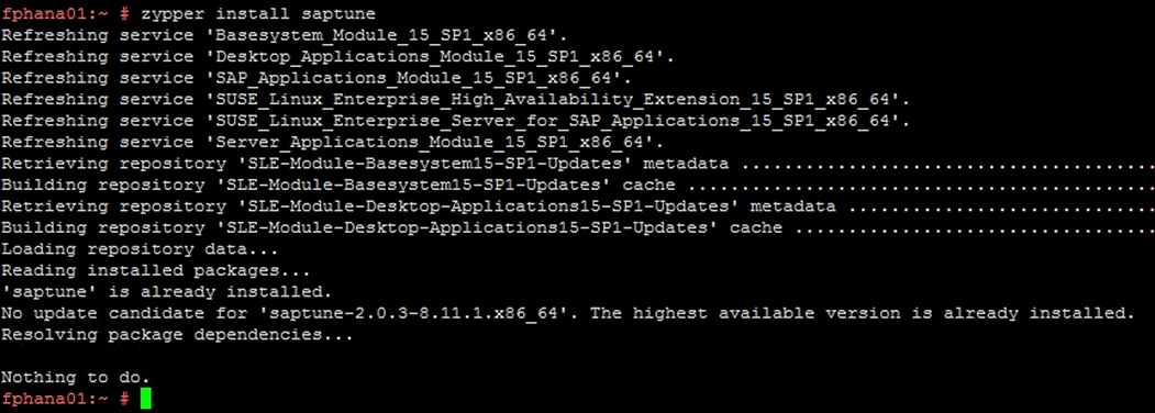
4. Configuration – activate saptune:
#saptune daemon start
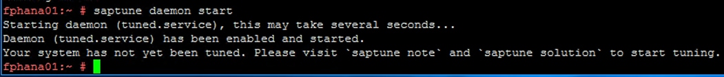
5. All available solutions and notes can be listed with:
#saptune solution list
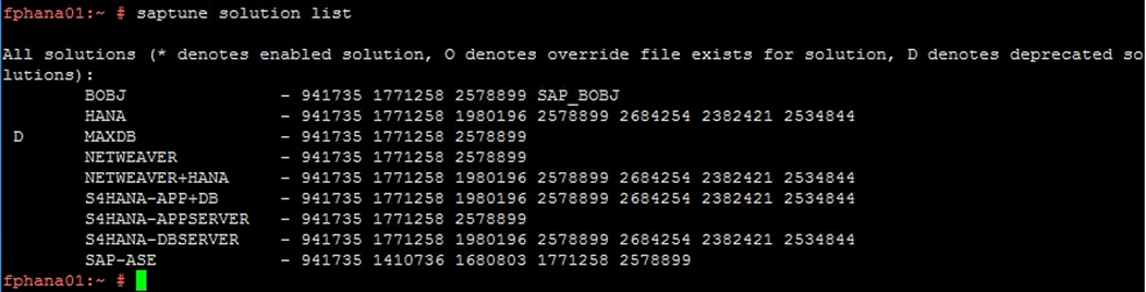
6. Apply SAP HANA solution/notes:
#saptune solution apply HANA
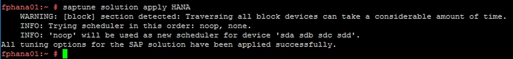
7. Verify the solution applied:
fphana01:~ # saptune solution verify HANA
WARNING: [block] section detected: Traversing all block devices can take a considerable amount of time.
INFO: Trying scheduler in this order: noop, none.
INFO: 'noop' will be used as new scheduler for device 'sda sdb sdc sdd'.
SAPNote, Version | Parameter | Expected | Override | Actual | Compliant
--------------------+------------------------------------+---------------------------+-----------+------------- --------------+-----------
1771258, 5 | LIMIT_@dba_hard_nofile | @dba hard nofile 65536 | | @dba hard no file 65536 | yes
1771258, 5 | LIMIT_@dba_soft_nofile | @dba soft nofile 65536 | | @dba soft no file 65536 | yes
1771258, 5 | LIMIT_@sapsys_hard_nofile | @sapsys hard nofile 65536 | | @sapsys hard nofile 65536 | yes
1771258, 5 | LIMIT_@sapsys_soft_nofile | @sapsys soft nofile 65536 | | @sapsys soft nofile 65536 | yes
1771258, 5 | LIMIT_@sdba_hard_nofile | @sdba hard nofile 65536 | | @sdba hard n ofile 65536 | yes
1771258, 5 | LIMIT_@sdba_soft_nofile | @sdba soft nofile 65536 | | @sdba soft n ofile 65536 | yes
1980196, 7 | vm.max_map_count | 2147483647 | | 2147483647 | yes
2382421, 36 | net.core.somaxconn | 4096 | | 4096 | yes
2382421, 36 | net.ipv4.tcp_max_syn_backlog | 8192 | | 8192 | yes
2382421, 36 | net.ipv4.tcp_slow_start_after_idle | 0 | | 0 | yes
2382421, 36 | net.ipv4.tcp_syn_retries | 8 | | 8 | yes
2382421, 36 | net.ipv4.tcp_timestamps | 1 | | 1 | yes
2382421, 36 | net.ipv4.tcp_window_scaling | 1 | | 1 | yes
2534844, 12 | kernel.shmmni | 32768 | | 32768 | yes
2578899, 20 | IO_SCHEDULER_sda | noop | | noop | yes
2578899, 20 | IO_SCHEDULER_sdb | noop | | noop | yes
2578899, 20 | IO_SCHEDULER_sdc | noop | | noop | yes
2578899, 20 | IO_SCHEDULER_sdd | noop | | noop | yes
2578899, 20 | rpm:tcsh | 6.20.00-4.9.1 | | 6.20.00-4.9. 1 | yes [3]
2578899, 20 | sysstat.service | start | | start | yes
2578899, 20 | uuidd.socket | start | | start | yes
2578899, 20 | vm.dirty_background_bytes | 314572800 | | 314572800 | yes
2578899, 20 | vm.dirty_bytes | 629145600 | | 629145600 | yes
2684254, 5 | KSM | 0 | | 0 | yes
2684254, 5 | THP | never | | never | yes
2684254, 5 | energy_perf_bias | all:0 | | all:0 | yes
2684254, 5 | force_latency | 70 | | 10 | yes
2684254, 5 | governor | all:performance | | all:performa nce | yes
2684254, 5 | grub:intel_idle.max_cstate | 1 | | NA | no [2] [3] [6]
2684254, 5 | grub:numa_balancing | disable | | NA | no [2] [3] [6]
2684254, 5 | grub:processor.max_cstate | 1 | | NA | no [2] [3] [6]
2684254, 5 | grub:transparent_hugepage | never | | NA | no [2] [3] [6]
2684254, 5 | kernel.numa_balancing | 0 | | 0 | yes
941735, 11 | ShmFileSystemSizeMB | 1113691 | | 1113691 | yes
941735, 11 | VSZ_TMPFS_PERCENT | 75 | | 75 | yes
941735, 11 | kernel.shmall | 1152921504606846720 | | 115292150460 6846720 | yes
941735, 11 | kernel.shmmax | 18446744073709551615 | | 184467440737 09551615 | yes
[2] setting is not available on the system
[3] value is only checked, but NOT set
[6] grub settings are mostly covered by other settings. See man page saptune-note(5) for details
Attention for SAP Note 2382421:
Hints or values not yet handled by saptune. So please read carefully, check and set manually, if needed:
# SAP HANA Parameters - all '.ini' file changes - not handled by saptune
#
# net.ipv4.ip_local_port_range
# As HANA uses a considerable number of connections for the internal
# communication, it makes sense to have as many client ports available as
# possible for this purpose.
# At the same time, you need to ensure that you explicitly exclude the ports
# used by processes and applications which bind to specific ports by adjusting
# parameter net.ipv4.ip_local_reserved_ports accordingly.
# If configured correctly, the SAP Host Agent takes care of adjusting this
# parameter and setting it manually is neither recommended nor required.
#
# The SAP Host Agent typically increases the port range typically to 9000-65499.
# If your port range is significantly different, for example when your lower
# port range starts with port 40000, please check the SAP Host Agent section
#
# net.ipv4.ip_local_reserved_ports
# This parameter specifies the ports which are reserved for known applications.
# You especially also have to specify the standard ports that are used by the
# SAP HANA. To find out which standard ports are used by your SAP HANA please
# refer to SAP Note 2477204.
# Ports listed in this parameter will not be used by automatic port assignment,
# while explicit port allocation behavior is unchanged.
# If configured correctly, the SAP Host Agent takes care of the standard ports
# used by SAP HANA if the instance numbers are provided accordingly. Setting
# this configuration manually is neither recommended nor required.
#
# net.ipv4.tcp_wmem and net.ipv4.tcp_rmem
# These parameters specify the minimum, default and maximum size of the TCP
# send and receive buffer.
# They are mostly relevant for system replication scenarios with a latency
# higher than usual.
# The maximum value should be equal to at least the bandwidth delay product of
# the relevant connection.
# Both, tcp_wmem and tcp_rmem, are specified as three values separated by
# blanks: minimum, default and maximum buffer size.
# Preconditions for these settings to take effect are:
# * net.core.wmem_max and net.core.rmem_max must not be lower than the
# respective maximum value.
# * TCP window scaling has been enabled by setting net.ipv4.tcp_window_scaling=1
#
# Example:
# net.ipv4.tcp_wmem = 4096 16384 4194304
#
# In this example, the current maximum is 4 MB. Given a 10 GBit/s connection
# with a latency of 1 ms, the required maximum would be
# 10 GBit/s * 1ms = 1.25 Mbytes, therefore the current setting is fine.
# If you want to saturate a 1 Gbit/s connection with a latency of 100 ms, the
# required maximum is 1 GBit/s * 100 ms = 12.5 Mbyte, so in this case the
# setting should be adjusted to at least 12.5 MByte.
# The minimum and the default buffer size do not need to be adjusted.
#
# net.core.wmem_max and net.core.rmem_max
# These settings define the maximum socket send and receive buffer size.
# To ensure complete functionality it must be ensured that the wmem_max and
# rmem_max values are at least the same as the respective maximum value of the
# parameters net.ipv4.tcp_wmem and net.ipv4.tcp_rmem.
#
# In landscapes where TCP timestamps are enabled please carefully evaluate if
# the following OS settings can be applied:
#
# net.ipv4.tcp_tw_reuse
# This setting allows HANA to reuse a client port immediately after the
# connection has been closed, even though the connection is still in TIME_WAIT
# state. A precondition for it to take effect is that TCP timestamps are
# enabled, i.e. net.ipv4.tcp_timestamps = 1, which is the default on most
# modern systems. Please note that this setting must not be applied if the HANA
# node needs to communicate with hosts behind a NAT firewall. Moreover, it must
# not be applied if not all hosts that use a TCP connection to communicate with
# the HANA node have TCP timestamps enabled. Otherwise you might encounter TCP
# connection issues after applying this configuration parameter.
#net.ipv4.tcp_tw_reuse = 1
#
# net.ipv4.tcp_tw_recycle
# This setting reduces the time a connection spends in the TIME_WAIT state.
# One precondition for it to take effect is that TCP timestamps are enabled,
# i.e. net.ipv4.tcp_timestamps = 1, which is the default on most modern systems.
# Please note that this setting must not be applied if the HANA node has to
# communicate with hosts behind a NAT firewall. Moreover, it must not be
# applied if not all hosts that use a TCP connection to communicate with the
# HANA node have TCP timestamps enabled. Otherwise you might encounter TCP
# connection issues after applying this configuration parameter.
#
# In case you are running ABAP Application Server instances on Windows, please
# refer to SAP Note 2789262 for further details on possible connection issues.
#
# Starting from SUSE Linux Enterprise Server (SLES) 12 SP4 and SLES 15 GA this
# configuration is removed without substitution.
#net.ipv4.tcp_tw_recycle = 1
#
Attention for SAP Note 2684254:
Hints or values not yet handled by saptune. So please read carefully, check and set manually, if needed:
# IBM EnergyScale for POWER8 Processor-Based Systems (applies to IBM Power systems only) - not handled by saptu ne!
# Intel Cluster-On-Die (COD) / sub-NUMA clustering technology
# HANA is not supported neither on Intel Cluster-On-Die (COD) technology nor on sub-NUMA clustering technology.
The system fully conforms to the tuning guidelines of the specified SAP solution.
fphana01:~ #
Synchronize NFS Domain Information For Proper Filesystem Mount
To be able to mount the volumes inside the HANA nodes, the v4-id-domain information of NFS enabled hana-svm providing the HANA persistence access should tally with domain information in /etc/idmapd.conf of the HANA nodes.
To synchronize the NFS domain, follow these steps:
1. On the NetApp command line fetch the information about the configured v4 domain, as shown below:

2. Make sure the same is updated in the ‘Domain’ filed of /etc/idmapd.conf file of HANA node.
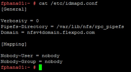
The configuration steps are identical for SAP HANA running on bare metal servers and on VMware virtual machines.
Table 10 shows the required variables used in this section.
| Variable |
Value |
Value used in the CVD |
| IP address LIF for SAP HANA data (on storage node1) |
<node01-data_lif01-ip> |
192.168.201.21 |
| IP address LIF for SAP HANA data (on storage node2) |
<node02-data_lif02-ip> |
192.168.201.22 |
| IP address LIF for SAP HANA log (on storage node1) |
<node01-log_lif01-ip> |
192.168.228.21 |
| IP address LIF for SAP HANA log (on storage node2) |
<node02-log_lif02-ip> |
192.168.228.22 |
Each SAP HANA host, either bare metal or VMware virtual machine, has two network interfaces connected to the storage network. One network interface is used to mount the log volumes, and the second interface is used to mount the data volumes for SAP HANA. The data and log volumes of the SAP HANA systems must be distributed to the storage nodes, as shown in Figure 75, so that a maximum of six data and six log volumes are stored on a single storage node.
The limitation of having six SAP HANA hosts per storage node is only valid for production SAP HANA systems for which the storage-performance key performance indicators defined by SAP must be fulfilled. For nonproduction SAP HANA systems, the maximum number is higher and must be determined during the sizing process.
Figure 75 Data and Log Volumes Distributed to the Storage Nodes
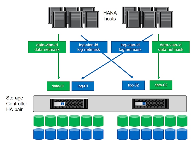
Configuring SAP HANA Scale-Up Systems
Figure 76 shows the volume configuration of four scale-up SAP HANA systems. The data and log volumes of each SAP HANA system are distributed to different storage controllers. For example, volume SID1_data_mnt00001 is configured on controller A, and volume SID1_log_mnt00001 is configured on controller B.
Figure 76 Four Scale-Up SAP HANA System Volume Configuration
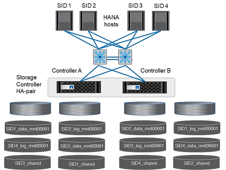
Configure a data volume, a log volume, and a volume for /hana/shared for each SAP HANA host. Table 11 lists an example configuration for scale-up SAP HANA systems.
Table 11 Volume Configuration for SAP HANA Scale-up Systems
| Purpose |
Aggregate 1 at |
Aggregate 2 at |
Aggregate 1 at |
Aggregate 2 at |
| Data, log, and shared volumes for system SID1 |
Data volume: SID1_data_mnt00001
|
Shared volume: SID1_shared |
|
Log volume: SID1_log_mnt00001 |
| Data, log, and shared volumes for system SID2 |
|
Log volume: SID2_log_mnt00001
|
Data volume: SID2_data_mnt00001 |
Shared volume: SID2_shared |
| Data, log, and shared volumes for system SID3 |
Shared volume: |
Data volume: SID3_data_mnt00001 |
Log volume: SID3_log_mnt00001
|
|
| Data, log, and shared volumes for system SID4 |
Log volume: SID4_log_mnt00001 |
|
Shared volume: |
Data volume: SID4_data_mnt00001
|
Table 12 shows an example of the mount point configuration for a scale-up system. To place the home directory of the sidadm user on the central storage, you should mount the /usr/sap/SID file system from the SID_shared volume.
Table 12 Mount Points for Scale-up Systems
| Junction Path |
Directory |
Mount Point at HANA Host |
| SID_data_mnt00001 |
|
/hana/data/SID/mnt00001 |
| SID_log_mnt00001 |
|
/hana/log/SID/mnt00001 |
| SID_shared |
usr-sap shared |
/usr/sap/SID /hana/shared/SID |
Configuration Example for an SAP HANA Scale-up System
The following examples show an SAP HANA database with SID=NF2 and a server RAM size of 1TB. For different server RAM sizes, the required volume sizes are different.
For a detailed description of the capacity requirements for SAP HANA, see the SAP HANA Storage Requirements white paper.
Figure 77 shows the volumes that must be created on the storage nodes and the network paths used.
Figure 77 Configuration Example for a SAP HANA Scale-up System
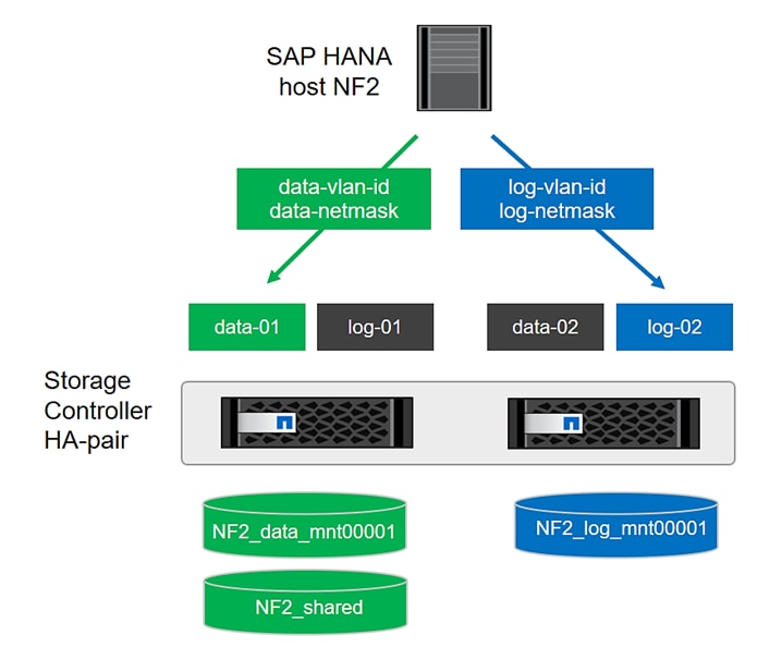
Create Data Volume and Adjust Volume Options
To create a data volume and adjust the volume options, run the following commands:
volume create -vserver hana-svm -volume NF2_data_mnt00001 -aggregate aggr1_1 -size 1TB -state online -junction-path /NF2_data_mnt00001 -policy nfs-hana -snapshot-policy none -percent-snapshot-space 0 -space-guarantee none
vol modify -vserver hana-svm -volume NF2_data_mnt00001 -snapdir-access false
set advanced
vol modify -vserver hana-svm -volume NF2_data_mnt00001 -atime-update false
set admin
Create a Log Volume and Adjust the Volume Options
To create a log volume and adjust the volume options, run the following commands:
volume create -vserver hana-svm -volume NF2_log_mnt00001 -aggregate aggr1_2 -size 512GB -state online -junction-path /NF2_log_mnt00001 -policy nfs-hana -snapshot-policy none -percent-snapshot-space 0 -space-guarantee none
vol modify -vserver hana-svm -volume NF2_log_mnt00001 -snapdir-access false
set advanced
vol modify -vserver hana-svm -volume NF2_log_mnt00001 -atime-update false
set admin
Create a HANA Shared Volume and adjust the Volume Options
To create a HANA shared volume and qtrees, and adjust the volume options, run the following commands:
volume create -vserver hana-svm -volume NF2_shared -aggregate aggr2_1 -size 1TB -state online -junction-path /NF2_shared -policy nfs-hana -snapshot-policy none -percent-snapshot-space 0 -space-guarantee none
vol modify -vserver hana-svm -volume NF2_shared -snapdir-access false
set advanced
vol modify -vserver hana-svm -volume NF2_shared -atime-update false
set admin
Create Directories for HANA Shared Volume
To create the required directories for the HANA shared volume mount the shared volume temporally and create the required directories
lnx-jumphost:/mnt # mount <storage-hostname>:/NF2_shared /mnt/tmp
lnx-jumphost:/mnt # cd /mnt/tmp
lnx-jumphost:/mnt/tmp # mkdir shared usr-sap
lnx-jumphost:/mnt # cd ..
lnx-jumphost:/mnt/tmp # umount /mnt/tmp
Update the Load-Sharing Mirror Relation
To update the load-sharing mirror relation, run the following command:
snapmirror update-ls-set -source-path hana-svm:hana_rootvol
Create Mount Points
To create the required mount-point directories, take one of the following actions:
mkdir -p /hana/data/NF2/mnt00001
mkdir -p /hana/log/NF2/mnt00001
mkdir -p /hana/shared
mkdir -p /usr/sap/NF2
chmod 777 -R /hana/log/NF2
chmod 777 -R /hana/data/NF2
chmod 777 -R /hana/shared
chmod 777 -R /usr/sap/NF2
Verify Domain Information Synchronization
To be able to mount the volumes inside the HANA nodes, the v4-id-domain information of NFS enabled hana-svm providing the HANA persistence access should tally with domain information in /etc/idmapd.conf of the HANA nodes.
Compare the value on NetApp and /etc/idmapd.conf file of the HANA node to verify they are synchronized.
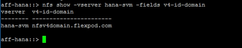
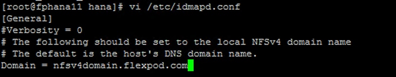
Mount File Systems
The mount options are identical for all file systems that are mounted to the host:
· /hana/data/NF2/mnt00001
· /hana/log/NF2/mnt00001
· /hana/shared
· /usr/sap/NF2
Table 13 lists the required mount options.
This example uses NFSv4.1 to connect the storage. However, NFSv3 is supported for SAP HANA single host systems.
For NFSv3, NFS locking must be switched off to avoid NFS lock cleanup operations in case of a software or server failure.
With NetApp® ONTAP® 9, the NFS transfer size can be configured up to 1MB. Specifically, with connections to the storage system over 10GBE, you must set the transfer size to 1MB to achieve the expected throughput values.
| Common Parameter |
NFSv4.1 |
NFS Transfer Size with ONTAP 9 |
| rw, bg, hard, timeo=600, intr, noatime |
vers=4, minorversion=1, lock |
rsize=1048576, wsize=1048576 |
To mount the file systems during system boot using the /etc/fstab configuration file, follow these steps:
![]() The following examples show an SAP HANA database with SID=NF2 using NFSv4.1 and an NFS transfer size of 1MB.
The following examples show an SAP HANA database with SID=NF2 using NFSv4.1 and an NFS transfer size of 1MB.
1. Add the file systems to the /etc/fstab configuration file.
cat /etc/fstab
<node01-data_lif01-ip>:/NF2_data_mnt00001 /hana/data/NF2/mnt00001 nfs rw,bg,vers=4,minorversion=1,hard,timeo=600,rsize=1048576,wsize=1048576,intr,noatime,lock 0 0
<node02-log_lif01-ip>:/NF2_log_mnt00001 /hana/log/NF2/mnt00001 nfs rw,bg,vers=4,minorversion=1,hard,timeo=600,rsize=1048576,wsize=1048576,intr,noatime,lock 0 0
<node01-data_lif01-ip>:/NF2_shared/usr-sap /usr/sap/NF2 nfs rw,bg,vers=4,minorversion=1,hard,timeo=600,rsize=1048576,wsize=1048576,intr,noatime,lock 0 0
<node01-data_lif01-ip>:/NF2_shared/shared /hana/shared nfs rw,bg,vers=4,minorversion=1,hard,timeo=600,rsize=1048576,wsize=1048576,intr,noatime,lock 0 0
2. Run mount –a to mount the file systems on the host.
3. Ensure the mounts have the ownership root:root and 777 for permissions, as set earlier.
![]() It is very important to ensure the ownership of mount points and their recursive directories are set to root:root and permissions to 777 before processing with SAP HANA installation.
It is very important to ensure the ownership of mount points and their recursive directories are set to root:root and permissions to 777 before processing with SAP HANA installation.
Persistent Memory Configuration Example
This section describes the use-case of a SAP HANA scale-up system implementation on a node configured with Intel Persistent Memory.
![]() For detailed information about Persistent Memory, see: Cisco UCS for SAP HANA with Intel Optane DC Persistent Memory Module whitepaper.
For detailed information about Persistent Memory, see: Cisco UCS for SAP HANA with Intel Optane DC Persistent Memory Module whitepaper.
The utility ipmctl is used for configuring and managing Intel Optane DC persistent memory modules (DCPMM) and the ndctl utility library is required for managing the libnvdimm (non-volatile memory device) sub-system in the Linux kernel.
To configure persistent memory, follow these steps:
1. ssh to the Server as root.
2. Install the ipmctl host utility:
# zypper in ipmctl
The following 2 NEW packages are going to be installed:
ipmctl libndctl6
2 new packages to install.
Overall download size: 487.7 KiB. Already cached: 0 B. After the operation, additional 3.4 MiB will be used.
Continue? [y/n/v/...? shows all options] (y): y
Retrieving package libndctl6-63-3.5.1.x86_64
(1/2), 87.6 KiB (188.0 KiB unpacked)
Retrieving: libndctl6-63-3.5.1.x86_64.rpm ................................[done]
Retrieving package ipmctl-01.00.00.3440-1.6.1.x86_64
(2/2), 400.1 KiB ( 3.2 MiB unpacked)
Retrieving: ipmctl-01.00.00.3440-1.6.1.x86_64.rpm ........................[done]
Checking for file conflicts: .............................................[done]
(1/2) Installing: libndctl6-63-3.5.1.x86_64...............................[done]
(2/2) Installing: ipmctl-01.00.00.3440-1.6.1.x86_64.......................[done]
3. Install the ndctl utility library:
# zypper in ndctl
The following NEW package is going to be installed:
ndctl
1 new package to install.
Overall download size: 147.2 KiB. Already cached: 0 B. After the operation, additional 252.1 KiB will be used.
Continue? [y/n/v/...? shows all options] (y): y
Retrieving package ndctl-63-3.5.1.x86_64
(1/1), 147.2 KiB (252.1 KiB unpacked)
Retrieving: ndctl-63-3.5.1.x86_64.rpm ....................................[done]
Checking for file conflicts: .............................................[done]
(1/1) Installing: ndctl-63-3.5.1.x86_64 ..................................[done]
4. Confirm the persistent memory modules are discovered in the system and verify the software can communicate with them.
# ipmctl show -dimm
DimmID | Capacity | HealthState | ActionRequired | LockState | FWVersion
==============================================================================
0x0001 | 252.4 GiB | Healthy | 0 | Disabled | 01.02.00.5375
0x0011 | 252.4 GiB | Healthy | 0 | Disabled | 01.02.00.5375
0x0021 | 252.4 GiB | Healthy | 0 | Disabled | 01.02.00.5375
0x0101 | 252.4 GiB | Healthy | 0 | Disabled | 01.02.00.5375
0x0111 | 252.4 GiB | Healthy | 0 | Disabled | 01.02.00.5375
0x0121 | 252.4 GiB | Healthy | 0 | Disabled | 01.02.00.5375
0x1001 | 252.4 GiB | Healthy | 0 | Disabled | 01.02.00.5375
0x1011 | 252.4 GiB | Healthy | 0 | Disabled | 01.02.00.5375
0x1021 | 252.4 GiB | Healthy | 0 | Disabled | 01.02.00.5375
0x1101 | 252.4 GiB | Healthy | 0 | Disabled | 01.02.00.5375
0x1111 | 252.4 GiB | Healthy | 0 | Disabled | 01.02.00.5375
0x1121 | 252.4 GiB | Healthy | 0 | Disabled | 01.02.00.5375
0x2001 | 252.4 GiB | Healthy | 0 | Disabled | 01.02.00.5375
0x2011 | 252.4 GiB | Healthy | 0 | Disabled | 01.02.00.5375
0x2021 | 252.4 GiB | Healthy | 0 | Disabled | 01.02.00.5375
0x2101 | 252.4 GiB | Healthy | 0 | Disabled | 01.02.00.5375
0x2111 | 252.4 GiB | Healthy | 0 | Disabled | 01.02.00.5375
0x2121 | 252.4 GiB | Healthy | 0 | Disabled | 01.02.00.5375
0x3001 | 252.4 GiB | Healthy | 0 | Disabled | 01.02.00.5375
0x3011 | 252.4 GiB | Healthy | 0 | Disabled | 01.02.00.5375
0x3021 | 252.4 GiB | Healthy | 0 | Disabled | 01.02.00.5375
0x3101 | 252.4 GiB | Healthy | 0 | Disabled | 01.02.00.5375
0x3111 | 252.4 GiB | Healthy | 0 | Disabled | 01.02.00.5375
0x3121 | 252.4 GiB | Healthy | 0 | Disabled | 01.02.00.5375
5. Create the goal:
# ipmctl create -goal
The following configuration will be applied:
SocketID | DimmID | MemorySize | AppDirect1Size | AppDirect2Size
==================================================================
0x0000 | 0x0001 | 0.0 GiB | 252.0 GiB | 0.0 GiB
0x0000 | 0x0011 | 0.0 GiB | 252.0 GiB | 0.0 GiB
0x0000 | 0x0021 | 0.0 GiB | 252.0 GiB | 0.0 GiB
0x0000 | 0x0101 | 0.0 GiB | 252.0 GiB | 0.0 GiB
0x0000 | 0x0111 | 0.0 GiB | 252.0 GiB | 0.0 GiB
0x0000 | 0x0121 | 0.0 GiB | 252.0 GiB | 0.0 GiB
0x0001 | 0x1001 | 0.0 GiB | 252.0 GiB | 0.0 GiB
0x0001 | 0x1011 | 0.0 GiB | 252.0 GiB | 0.0 GiB
0x0001 | 0x1021 | 0.0 GiB | 252.0 GiB | 0.0 GiB
0x0001 | 0x1101 | 0.0 GiB | 252.0 GiB | 0.0 GiB
0x0001 | 0x1111 | 0.0 GiB | 252.0 GiB | 0.0 GiB
0x0001 | 0x1121 | 0.0 GiB | 252.0 GiB | 0.0 GiB
0x0002 | 0x2001 | 0.0 GiB | 252.0 GiB | 0.0 GiB
0x0002 | 0x2011 | 0.0 GiB | 252.0 GiB | 0.0 GiB
0x0002 | 0x2021 | 0.0 GiB | 252.0 GiB | 0.0 GiB
0x0002 | 0x2101 | 0.0 GiB | 252.0 GiB | 0.0 GiB
0x0002 | 0x2111 | 0.0 GiB | 252.0 GiB | 0.0 GiB
0x0002 | 0x2121 | 0.0 GiB | 252.0 GiB | 0.0 GiB
0x0003 | 0x3001 | 0.0 GiB | 252.0 GiB | 0.0 GiB
0x0003 | 0x3011 | 0.0 GiB | 252.0 GiB | 0.0 GiB
0x0003 | 0x3021 | 0.0 GiB | 252.0 GiB | 0.0 GiB
0x0003 | 0x3101 | 0.0 GiB | 252.0 GiB | 0.0 GiB
0x0003 | 0x3111 | 0.0 GiB | 252.0 GiB | 0.0 GiB
0x0003 | 0x3121 | 0.0 GiB | 252.0 GiB | 0.0 GiB
Do you want to continue? [y/n] y
Created following region configuration goal
SocketID | DimmID | MemorySize | AppDirect1Size | AppDirect2Size
==================================================================
0x0000 | 0x0001 | 0.0 GiB | 252.0 GiB | 0.0 GiB
0x0000 | 0x0011 | 0.0 GiB | 252.0 GiB | 0.0 GiB
0x0000 | 0x0021 | 0.0 GiB | 252.0 GiB | 0.0 GiB
0x0000 | 0x0101 | 0.0 GiB | 252.0 GiB | 0.0 GiB
0x0000 | 0x0111 | 0.0 GiB | 252.0 GiB | 0.0 GiB
0x0000 | 0x0121 | 0.0 GiB | 252.0 GiB | 0.0 GiB
0x0001 | 0x1001 | 0.0 GiB | 252.0 GiB | 0.0 GiB
0x0001 | 0x1011 | 0.0 GiB | 252.0 GiB | 0.0 GiB
0x0001 | 0x1021 | 0.0 GiB | 252.0 GiB | 0.0 GiB
0x0001 | 0x1101 | 0.0 GiB | 252.0 GiB | 0.0 GiB
0x0001 | 0x1111 | 0.0 GiB | 252.0 GiB | 0.0 GiB
0x0001 | 0x1121 | 0.0 GiB | 252.0 GiB | 0.0 GiB
0x0002 | 0x2001 | 0.0 GiB | 252.0 GiB | 0.0 GiB
0x0002 | 0x2011 | 0.0 GiB | 252.0 GiB | 0.0 GiB
0x0002 | 0x2021 | 0.0 GiB | 252.0 GiB | 0.0 GiB
0x0002 | 0x2101 | 0.0 GiB | 252.0 GiB | 0.0 GiB
0x0002 | 0x2111 | 0.0 GiB | 252.0 GiB | 0.0 GiB
0x0002 | 0x2121 | 0.0 GiB | 252.0 GiB | 0.0 GiB
0x0003 | 0x3001 | 0.0 GiB | 252.0 GiB | 0.0 GiB
0x0003 | 0x3011 | 0.0 GiB | 252.0 GiB | 0.0 GiB
0x0003 | 0x3021 | 0.0 GiB | 252.0 GiB | 0.0 GiB
0x0003 | 0x3101 | 0.0 GiB | 252.0 GiB | 0.0 GiB
0x0003 | 0x3111 | 0.0 GiB | 252.0 GiB | 0.0 GiB
0x0003 | 0x3121 | 0.0 GiB | 252.0 GiB | 0.0 GiB
A reboot is required to process new memory allocation goals.
6. Reboot the server for the new memory allocations.
7. Verify the regions created:
# ipmctl show -region
SocketID | ISetID | PersistentMemoryType | Capacity | FreeCapacity | HealthState
================================================================================================
0x0000 | 0x96467f486ebf2ccc | AppDirect | 1512.0 GiB | 1512.0 GiB | Healthy
0x0001 | 0x163e7f48a6eb2ccc | AppDirect | 1512.0 GiB | 1512.0 GiB | Healthy
0x0002 | 0xd8787f48c4af2ccc | AppDirect | 1512.0 GiB | 1512.0 GiB | Healthy
0x0003 | 0x1ac47f482bb32ccc | AppDirect | 1512.0 GiB | 1512.0 GiB | Healthy
8. Create a name space for each region; on a server with a total of 4 CPU and invoke the command four times.
ndctl create-namespace
9. List the active name spaces created before
# ndctl list
[
{
"dev":"namespace24.0",
"mode":"fsdax",
"map":"dev",
"size":1598128390144,
"uuid":"60f803c0-d6f6-4a0c-b522-393e74d25279",
"blockdev":"pmem24"
},
{
"dev":"namespace26.0",
"mode":"fsdax",
"map":"dev",
"size":1598128390144,
"uuid":"306b6e4b-f2e0-49b0-95e8-0d44602c2204",
"blockdev":"pmem26"
},
{
"dev":"namespace25.0",
"mode":"fsdax",
"map":"dev",
"size":1598128390144,
"uuid":"b08acc26-a196-4de1-ae1c-b088058410ee",
"blockdev":"pmem25"
},
{
"dev":"namespace27.0",
"mode":"fsdax",
"map":"dev",
"size":1598128390144,
"uuid":"1a20712f-cce0-49e9-b871-3b424c740ff4",
"blockdev":"pmem27"
}
]
10. Create a file system and mount the persistent memory modules:
mkfs -t xfs -f /dev/pmem24
mkfs -t xfs -f /dev/pmem25
mkfs -t xfs -f /dev/pmem26
mkfs -t xfs -f /dev/pmem27
mkdir -p /hana/pmem/nvmem0
mkdir -p /hana/pmem/nvmem1
mkdir -p /hana/pmem/nvmem2
mkdir -p /hana/pmem/nvmem3
mount -t xfs -o dax /dev/pmem24 /hana/pmem/nvmem0
mount -t xfs -o dax /dev/pmem25 /hana/pmem/nvmem1
mount -t xfs -o dax /dev/pmem26 /hana/pmem/nvmem2
mount -t xfs -o dax /dev/pmem26 /hana/pmem/nvmem3
11. Add the mount points to the /etc/fstab file to make them permanent:
# vi /etc/fstab
/dev/pmem24 on /hana/pmem/nvmem0 type xfs (rw,relatime,attr2,dax,inode64,noquota)
/dev/pmem25 on /hana/pmem/nvmem1 type xfs (rw,relatime,attr2,dax,inode64,noquota)
/dev/pmem26 on /hana/pmem/nvmem2 type xfs (rw,relatime,attr2,dax,inode64,noquota)
/dev/pmem37 on /hana/pmem/nvmem3 type xfs (rw,relatime,attr2,dax,inode64,noquota)
Configure the Base Path to Use Persistent Memory
Post the SAP HANA system install the directory that SAP HANA uses as its base path must point to the XFS file system. Define the base path location with the configuration parameter basepath_persistent_memory_volumes in the (persistence) section of the SAP HANA global.ini file. This section can contain multiple locations separated by semicolons.
To configure the base path, follow these steps:
1. Changes to this parameter require a restart of SAP HANA services.
[persistence]
basepath_datavolumes = /hana/data/<SID>
basepath_logvolumes = /hana/log/<SID>
basepath_persistent_memory_volumes = /hana/pmem/nvmem0;/hana/pmem/nvmem1;/hana/pmem/nvmem2;/hana/pmem/nvmem3
Configuration for SAP HANA Scale-Out System
Figure 78 shows the volume configuration of a 4+1 SAP HANA system. The data and log volumes of each SAP HANA host are distributed to different storage controllers. For example, volume SID1_data1_mnt00001 is configured on controller A, and volume SID1_log1_mnt00001 is configured on controller B.
Figure 78 Volume Layout for SAP HANA Scale-Out System
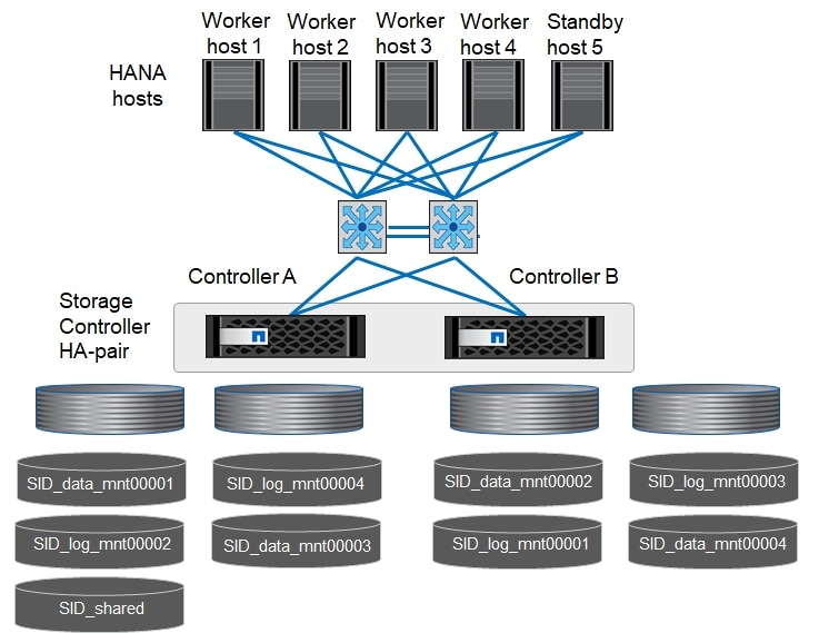
For each SAP HANA host, a data volume and a log volume are created. /hana/shared is used by all hosts of the SAP HANA system. Table 14 shows an example configuration for a scale out SAP HANA system with four active hosts.
Table 14 Volume Configuration for SAP HANA Scale-Out System
| Purpose |
Aggregate 1 at Controller A |
Aggregate 2 at Controller A |
Aggregate 1 at Controller B |
Aggregate 2 at Controller B |
| Data and log volumes for node 1 |
Data volume: SID_data_mnt00001 |
|
Log volume: SID_log_mnt00001 |
|
| Data and log volumes for node 2 |
Log volume: SID_log_mnt00002 |
|
Data volume: SID_data_mnt00002 |
|
| Data and log volumes for node 3 |
|
Data volume: SID_data_mnt00003 |
|
Log volume: SID_log_mnt00003 |
| Data and log volumes for node 4 |
|
Log volume: SID_log_mnt00004 |
|
Data volume: SID_data_mnt00004 |
| Shared volume for all hosts |
Shared volume: SID_shared |
N/A |
N/A |
N/A |
Table 15 lists the configuration and mount points of a SAP HANA scale out system with four active nodes. To place the home directories of the sidadm user of each host on the central storage, the /usr/sap/SID file systems are mounted from the SID_shared volume.
Table 15 Mount Points for Scale-Out System
| Junction Path |
Directory |
Mount Point at SAP HANA Host |
Note |
| SID_data_mnt00001 |
|
/hana/data/SID/mnt00001 |
Mounted at all hosts |
| SID_log_mnt00001 |
|
/hana/log/SID/mnt00001 |
Mounted at all hosts |
| SID_data_mnt00002 |
|
/hana/data/SID/mnt00002 |
Mounted at all hosts |
| SID_log_mnt00002 |
|
/hana/log/SID/mnt00002 |
Mounted at all hosts |
| SID_data_mnt00003 |
|
/hana/data/SID/mnt00003 |
Mounted at all hosts |
| SID_log_mnt00003 |
|
/hana/log/SID/mnt00003 |
Mounted at all hosts |
| SID_data_mnt00004 |
|
/hana/data/SID/mnt00004 |
Mounted at all hosts |
| SID_log_mnt00004 |
|
/hana/log/SID/mnt00004 |
Mounted at all hosts |
| SID_shared |
shared |
/hana/shared/SID |
Mounted at all hosts |
| SID_shared |
usr-sap-host1 |
/usr/sap/SID |
Mounted at host 1 |
| SID_shared |
usr-sap-host2 |
/usr/sap/SID |
Mounted at host 2 |
| SID_shared |
usr-sap-host3 |
/usr/sap/SID |
Mounted at host 3 |
| SID_shared |
usr-sap-host4 |
/usr/sap/SID |
Mounted at host 4 |
| SID_shared |
usr-sap-host5 |
/usr/sap/SID |
Mounted at host 5 |
Configuration Example for an SAP HANA Scale-Out System
The following examples show a 4+1 SAP HANA scale-out system with SID=NF3 and a server with a RAM size of 2TB. For different server RAM sizes, the required volume sizes are different.
For a detailed description of the capacity requirements for SAP HANA, see the SAP HANA Storage Requirements white paper.
Figure 79 shows the volumes that must be created on the storage nodes and the network paths used.
Figure 79 Configuration Example for SAP HANA Scale-Out System
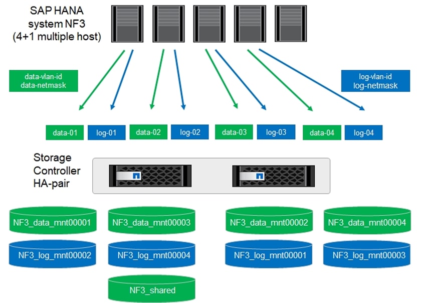
Create Data Volumes and Adjust Volume Options
To create data volumes and adjust the volume options, run the following commands:
volume create -vserver hana-svm -volume NF3_data_mnt00001 -aggregate aggr1_1 -size 2500GB -state online -junction-path /NF3_data_mnt00001 -policy nfs-hana -snapshot-policy none -percent-snapshot-space 0 -space-guarantee none
volume create -vserver hana-svm -volume NF3_data_mnt00002 -aggregate aggr1_2 -size 2500GB -state online -junction-path /NF3_data_mnt00002 -policy nfs-hana -snapshot-policy none -percent-snapshot-space 0 -space-guarantee none
volume create -vserver hana-svm -volume NF3_data_mnt00003 -aggregate aggr2_1 -size 2500GB -state online -junction-path /NF3_data_mnt00003 -policy nfs-hana -snapshot-policy none -percent-snapshot-space 0 -space-guarantee none
volume create -vserver hana-svm -volume NF3_data_mnt00004 -aggregate aggr2_2 -size 2500GB -state online -junction-path /NF3_data_mnt00004 -policy nfs-hana -snapshot-policy none -percent-snapshot-space 0 -space-guarantee none
vol modify -vserver hana-svm -volume NF3_data_mnt0000* -snapdir-access false
set advanced
vol modify -vserver hana-svm -volume NF3_data_mnt0000* -atime-update false
set admin
Create Log Volume and Adjust Volume Options
To create a log volume and adjust the volume options, run the following commands:
volume create -vserver hana-svm -volume NF3_log_mnt00001 -aggregate aggr1_2 -size 512GB -state online -junction-path /NF3_log_mnt00001 -policy nfs-hana -snapshot-policy none -percent-snapshot-space 0 -space-guarantee none
volume create -vserver hana-svm -volume NF3_log_mnt00002 -aggregate aggr1_1 -size 512GB -state online -junction-path /NF3_log_mnt00002 -policy nfs-hana -snapshot-policy none -percent-snapshot-space 0 -space-guarantee none
volume create -vserver hana-svm -volume NF3_log_mnt00003 -aggregate aggr2_2 -size 512GB -state online -junction-path /NF3_log_mnt00003 -policy nfs-hana -snapshot-policy none -percent-snapshot-space 0 -space-guarantee none
volume create -vserver hana-svm -volume NF3_log_mnt00004 -aggregate aggr2_1 -size 512GB -state online -junction-path /NF3_log_mnt00004 -policy nfs-hana -snapshot-policy none -percent-snapshot-space 0 -space-guarantee none
vol modify -vserver hana-svm -volume NF3_log_mnt0000* -snapdir-access false
set advanced
vol modify -vserver hana-svm -volume NF3_log_mnt0000* -atime-update false
set admin
Create HANA Shared Volume and Adjust Volume Options
To create a HANA shared volume and adjust the volume options, run the following commands:
volume create -vserver hana-svm -volume NF3_shared -aggregate aggr1_1 -size 2500GB -state online -junction-path /NF3_shared -policy nfs-hana -snapshot-policy none -percent-snapshot-space 0 -space-guarantee none
vol modify -vserver hana-svm -volume NF3_shared -snapdir-access false
set advanced
vol modify -vserver hana-svm -volume NF3_shared -atime-update false
set admin
Create Directories of HANA Shared Volume
To create the required directories for the HANA shared volume mount the shared volume temporally and create the required directories:
lnx-jumphost:/mnt # mount <storage-hostname>:/NF3_shared /mnt/tmp
lnx-jumphost:/mnt # cd /mnt/tmp
lnx-jumphost:/mnt/tmp # mkdir shared
lnx-jumphost:/mnt/tmp # mkdir usr-sap-host1
lnx-jumphost:/mnt/tmp # mkdir usr-sap-host2
lnx-jumphost:/mnt/tmp # mkdir usr-sap-host3
lnx-jumphost:/mnt/tmp # mkdir usr-sap-host4
lnx-jumphost:/mnt/tmp # mkdir usr-sap-host5
lnx-jumphost:/mnt # cd ..
lnx-jumphost:/mnt/tmp # umount /mnt/tmp
Update Load-Sharing Mirror Relation
To update the load-sharing mirror relation, run the following command:
snapmirror update-ls-set -source-path hana-svm:hana_rootvol
Create Mount Points
For a scale out system, create mount points and set the permissions on all worker and standby hosts as follows:
1. Create mount points for the first worker host.
mkdir -p /hana/data/NF3/mnt00001
mkdir -p /hana/data/NF3/mnt00002
mkdir -p /hana/data/NF3/mnt00003
mkdir -p /hana/data/NF3/mnt00004
mkdir -p /hana/log/NF3/mnt00001
mkdir -p /hana/log/NF3/mnt00002
mkdir -p /hana/log/NF3/mnt00003
mkdir -p /hana/log/NF3/mnt00004
mkdir -p /hana/shared
mkdir -p /usr/sap/NF3
chmod 777 -R /hana/log/NF3
chmod 777 -R /hana/data/NF3
chmod 777 -R /hana/shared
chmod 777 -R /usr/sap/NF3
2. Create mount points for the second worker host.
mkdir -p /hana/data/NF3/mnt00001
mkdir -p /hana/data/NF3/mnt00002
mkdir -p /hana/data/NF3/mnt00003
mkdir -p /hana/data/NF3/mnt00004
mkdir -p /hana/log/NF3/mnt00001
mkdir -p /hana/log/NF3/mnt00002
mkdir -p /hana/log/NF3/mnt00003
mkdir -p /hana/log/NF3/mnt00004
mkdir -p /hana/shared
mkdir -p /usr/sap/NF3
chmod 777 -R /hana/log/NF3
chmod 777 -R /hana/data/NF3
chmod 777 -R /hana/shared
chmod 777 -R /usr/sap/NF3
3. Create mount points for the third worker host.
mkdir -p /hana/data/NF3/mnt00001
mkdir -p /hana/data/NF3/mnt00002
mkdir -p /hana/data/NF3/mnt00003
mkdir -p /hana/data/NF3/mnt00004
mkdir -p /hana/log/NF3/mnt00001
mkdir -p /hana/log/NF3/mnt00002
mkdir -p /hana/log/NF3/mnt00003
mkdir -p /hana/log/NF3/mnt00004
mkdir -p /hana/shared
mkdir -p /usr/sap/NF3
chmod 777 -R /hana/log/NF3
chmod 777 -R /hana/data/NF3
chmod 777 -R /hana/shared
chmod 777 -R /usr/sap/NF3
4. Create mount points for the fourth worker host.
mkdir -p /hana/data/NF3/mnt00001
mkdir -p /hana/data/NF3/mnt00002
mkdir -p /hana/data/NF3/mnt00003
mkdir -p /hana/data/NF3/mnt00004
mkdir -p /hana/log/NF3/mnt00001
mkdir -p /hana/log/NF3/mnt00002
mkdir -p /hana/log/NF3/mnt00003
mkdir -p /hana/log/NF3/mnt00004
mkdir -p /hana/shared
mkdir -p /usr/sap/NF3
chmod 777 -R /hana/log/NF3
chmod 777 -R /hana/data/NF3
chmod 777 -R /hana/shared
chmod 777 -R /usr/sap/NF3
5. Create mount points for the standby host.
mkdir -p /hana/data/NF3/mnt00001
mkdir -p /hana/data/NF3/mnt00002
mkdir -p /hana/data/NF3/mnt00003
mkdir -p /hana/data/NF3/mnt00004
mkdir -p /hana/log/NF3/mnt00001
mkdir -p /hana/log/NF3/mnt00002
mkdir -p /hana/log/NF3/mnt00003
mkdir -p /hana/log/NF3/mnt00004
mkdir -p /hana/shared
mkdir -p /usr/sap/NF3
chmod 777 -R /hana/log/NF3
chmod 777 -R /hana/data/NF3
chmod 777 -R /hana/shared
chmod 777 -R /usr/sap/NF3
Verify Domain Information Synchronization
To be able to mount the volumes inside the HANA nodes, the v4-id-domain information of NFS enabled hana-svm providing the HANA persistence access should tally with domain information in /etc/idmapd.conf of the HANA nodes.
Compare the value on NetApp and /etc/idmapd.conf file of all HANA nodes to verify they are synchronized.

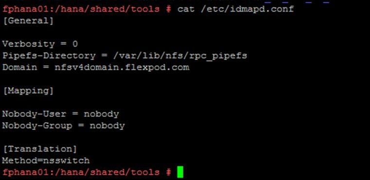
Mount File Systems
The mount options are identical for all file systems that are mounted to the hosts:
· /hana/data/NF3/mnt00001
· /hana/data/NF3/mnt00002
· /hana/data/NF3/mnt00003
· /hana/data/NF3/mnt00004
· /hana/log/NF3/mnt00001
· /hana/log/NF3/mnt00002
· /hana/log/NF3/mnt00003
· /hana/log/NF3/mnt00004
· /hana/shared
· /usr/sap/NF3
Table 16 shows the required mount options.
With ONTAP 9, the NFS transfer size can be configured up to 1MB. Specifically, with 40GbE connections to the storage system, you must set the transfer size to 1MB to achieve the expected throughput values.
| Common Parameter |
NFSv4.1 |
NFS Transfer Size with ONTAP 9 |
| rw,bg,hard, timeo=600,intr, noatime |
vers=4,minorversion=1,lock |
rsize=1048576, wsize=1048576 |
The following examples show an SAP HANA database with SID=NF3 using NFSv4.1 and an NFS transfer size of 1MB. To mount the file systems during system boot using the /etc/fstab configuration file, follow these steps:
1. For a scale out system, add the required file systems to the /etc/fstab configuration file on all hosts.
![]() The /usr/sap/NF3 file system is different for each database host. The following example shows /NF3_shared/usr_sap_host1:
The /usr/sap/NF3 file system is different for each database host. The following example shows /NF3_shared/usr_sap_host1:
cat /etc/fstab
<node01-data_lif01-ip>:/NF3_data_mnt00001 /hana/data/NF3/mnt00001 nfs rw,bg,vers=4,minorversion=1,hard,timeo=600,rsize=1048576,wsize=1048576,intr,noatime,nolock 0 0
<node02-data_lif01-ip>:/NF3_data_mnt00002 /hana/data/NF3/mnt00002 nfs rw,bg,vers=4,minorversion=1,hard,timeo=600,rsize=1048576,wsize=1048576,intr,noatime,nolock 0 0
<node01-data_lif02-ip>:/NF3_data_mnt00003 /hana/data/NF3/mnt00003 nfs rw,bg,vers=4,minorversion=1,hard,timeo=600,rsize=1048576,wsize=1048576,intr,noatime,nolock 0 0
<node02-data_lif02-ip>:/NF3_data_mnt00004 /hana/data/NF3/mnt00004 nfs rw,bg,vers=4,minorversion=1,hard,timeo=600,rsize=1048576,wsize=1048576,intr,noatime,nolock 0 0
<node02-log_lif01-ip>:/NF3_log_mnt00001 /hana/log/NF3/mnt00001 nfs rw,bg,vers=4,minorversion=1,hard,timeo=600,rsize=1048576,wsize=1048576,intr,noatime,nolock 0 0
<node01-log_lif01-ip>:/NF3_log_mnt00002 /hana/log/NF3/mnt00002 nfs rw,bg,vers=4,minorversion=1,hard,timeo=600,rsize=1048576,wsize=1048576,intr,noatime,nolock 0 0
<node02-log_lif02-ip>:/NF3_log_mnt00003 /hana/log/NF3/mnt00003 nfs rw,bg,vers=4,minorversion=1,hard,timeo=600,rsize=1048576,wsize=1048576,intr,noatime,nolock 0 0
<node01-log_lif02-ip>:/NF3_log_mnt00004 /hana/log/NF3/mnt00004 nfs rw,bg,vers=4,minorversion=1,hard,timeo=600,rsize=1048576,wsize=1048576,intr,noatime,nolock 0 0
<node01-data_lif01-ip>:/NF3_shared/usr-sap-host1 /usr/sap/NF3 nfs rw,bg,vers=4,minorversion=1,hard,timeo=600,rsize=1048576,wsize=1048576,intr,noatime,nolock 0 0
<node01-data_lif01-ip>:/NF3_shared/shared /hana/shared nfs rw,bg, vers=4,minorversion=1,hard,timeo=600,rsize=1048576,wsize=1048576,intr,noatime,nolock 0 0
2. Run mount –a on each host to mount the file systems.
3. Ensure the mounts have the ownership root:root and 777 for permissions, as set earlier.
![]() It is very important to ensure the ownership of mount points and their recursive directories are set to root:root and permissions to 777 before processing with SAP HANA installation.
It is very important to ensure the ownership of mount points and their recursive directories are set to root:root and permissions to 777 before processing with SAP HANA installation.
4. For scale-out system, all nodes should be able to resolve Internal network IP address. Below is an example of 4 node scale-out system host file with all the network defined in the /etc/hosts file:
cat /etc/hosts
#
# hosts This file describes a number of hostname-to-address
# mappings for the TCP/IP subsystem. It is mostly
# used at boot time, when no name servers are running.
# On small systems, this file can be used instead of a
# "named" name server.
# Syntax:
#
# IP-Address Full-Qualified-Hostname Short-Hostname
#
127.0.0.1 localhost
# special IPv6 addresses
::1 localhost ipv6-localhost ipv6-loopback
fe00::0 ipv6-localnet
ff00::0 ipv6-mcastprefix
ff02::1 ipv6-allnodes
ff02::2 ipv6-allrouters
ff02::3 ipv6-allhosts
192.168.201.21 hana-data-a
192.168.201.22 hana-data-b
192.168.228.21 hana-log-a
192.168.228.22 hana-log-b
#
## Inter-node Network
#
192.168.220.201 fphana01.ciscolab.local fphana01
192.168.220.201 fphana02.ciscolab.local fphana02
192.168.220.202 fphana03.ciscolab.local fphana03
192.168.220.203 fphana04.ciscolab.local fphana04
#
## HANA Data Network
#
192.168.201.200 fphana01d.ciscolab.local fphana01d
192.168.201.201 fphana02d.ciscolab.local fphana02d
192.168.201.202 fphana03d.ciscolab.local fphana03d
192.168.201.203 fphana04d.ciscolab.local fphana04d
#
## HANA Log Network
#
192.168.228.200 fphana01l.ciscolab.local fphana01l
192.168.228.201 fphana02l.ciscolab.local fphana02l
192.168.228.202 fphana03l.ciscolab.local fphana03l
192.168.228.203 fphana04l.ciscolab.local fphana04l
#
## Client Network
#
192.168.222.200 fphana01c.ciscolab.local fphana01c
192.168.222.201 fphana02c.ciscolab.local fphana02c
192.168.222.202 fphana03c.ciscolab.local fphana03c
192.168.222.203 fphana04c.ciscolab.local fphana04c
#
## AppServer Network
#
192.168.223.200 fphana01a.ciscolab.local fphana01a
192.168.223.201 fphana02a.ciscolab.local fphana02a
192.168.223.202 fphana03a.ciscolab.local fphana03a
192.168.223.203 fphana04a.ciscolab.local fphana04a
#
## Admin Network
#
192.168.76.200 fphana01m.ciscolab.local fphana01m
192.168.76.201 fphana02m.ciscolab.local fphana02m
192.168.76.202 fphana03m.ciscolab.local fphana03m
192.168.76.203 fphana04m.ciscolab.local fphana04m
#
## Backup Network
#
192.168.224.200 fphana01b.ciscolab.local fphana01b
192.168.224.201 fphana02b.ciscolab.local fphana02b
192.168.224.202 fphana03b.ciscolab.local fphana03b
192.168.224.203 fphana04b.ciscolab.local fphana04b
#
## HANA shared Network
#
192.168.130.201 fphana01s.ciscolab.local fphana01s
192.168.130.202 fphana01s.ciscolab.local fphana02s
192.168.130.203 fphana01s.ciscolab.local fphana01s
192.168.130.204 fphana01s.ciscolab.local fphana01s
5. A sample global.ini file from the installed SAP HANA scale out system is as below:
[communication]
listeninterface = .global
[multidb]
mode = multidb
database_isolation = low
singletenant = yes
[persistence]
basepath_datavolumes = /hana/data/NF3
basepath_logvolumes = /hana/log/NF3
For information about the SAP HANA installation, please use the official SAP documentation, which describes the installation process with and without the SAP unified installer.
![]() Read the SAP Notes before you start the installation (see Important SAP Notes). These SAP Notes contain the latest information about the installation, as well as corrections to the installation documentation.
Read the SAP Notes before you start the installation (see Important SAP Notes). These SAP Notes contain the latest information about the installation, as well as corrections to the installation documentation.
SAP HANA Server Installation Guide
All other SAP installation and administration documentation is available here: http://service.sap.com/instguides
Important SAP Notes
Read the following SAP Notes before you start the installation. These SAP Notes contain the latest information about the installation, as well as corrections to the installation documentation.
The latest SAP Notes can be found here: https://service.sap.com/notes.
SAP HANA IMDB Related Notes
SAP Note 1514967 - SAP HANA: Central Note
SAP Note 1523337 - SAP HANA Database: Central Note
SAP Note 2000003 - FAQ: SAP HANA
SAP Note 1730999![]() - Configuration changes in SAP HANA appliance
- Configuration changes in SAP HANA appliance
SAP Note 1514966![]() - SAP HANA 1.0: Sizing SAP In-Memory Database
- SAP HANA 1.0: Sizing SAP In-Memory Database
SAP Note 1780950![]() - Connection problems due to host name resolution
- Connection problems due to host name resolution
SAP Note 1743225![]() - SAP HANA: Potential failure of connections with scale out nodes
- SAP HANA: Potential failure of connections with scale out nodes
SAP Note 1755396![]() - Released DT solutions for SAP HANA with disk replication
- Released DT solutions for SAP HANA with disk replication
SAP Note 1890444![]() - HANA system slow due to CPU power save mode
- HANA system slow due to CPU power save mode
SAP Note 1681092 - Support for multiple SAP HANA databases on a single SAP HANA appliance
SAP Note 1514966 - SAP HANA: Sizing SAP HANA Database
SAP Note 1637145 - SAP BW on HANA: Sizing SAP HANA Database
SAP Note 1793345 - Sizing for Suite on HANA
Linux Related Notes
SAP Note 2235581 - SAP HANA: Supported Operating Systems
2578899 - SUSE Linux Enterprise Server 15: Installation Note
SAP Note 2009879 - SAP HANA Guidelines for Red Hat Enterprise Linux (RHEL)
SAP Note 2292690 - SAP HANA DB: Recommended OS settings for RHEL 7
SAP Note 1731000![]() - Non-recommended configuration changes
- Non-recommended configuration changes
SAP Note 2382421 - Optimizing the Network Configuration on HANA- and OS-Level
SAP Note 1557506![]() - Linux paging improvements
- Linux paging improvements
SAP Note 1740136![]() - SAP HANA: wrong mount option may lead to corrupt persistency
- SAP HANA: wrong mount option may lead to corrupt persistency
SAP Note 1829651![]() - Time zone settings in SAP HANA scale out landscapes
- Time zone settings in SAP HANA scale out landscapes
SAP Application Related Notes
SAP Note 1658845![]() - SAP HANA DB hardware check
- SAP HANA DB hardware check
SAP Note 1637145![]() - SAP BW on SAP HANA: Sizing SAP In-Memory Database
- SAP BW on SAP HANA: Sizing SAP In-Memory Database
SAP Note 1661202![]() - Support for multiple applications on SAP HANA
- Support for multiple applications on SAP HANA
SAP Note 1681092![]() - Support for multiple SAP HANA databases one HANA aka Multi SID
- Support for multiple SAP HANA databases one HANA aka Multi SID
SAP Note 1577128![]() - Supported clients for SAP HANA 1.0
- Supported clients for SAP HANA 1.0
SAP Note 1808450![]() - Homogenous system landscape for on BW-HANA
- Homogenous system landscape for on BW-HANA
SAP Note 1976729 - Application Component Hierarchy for SAP HANA
SAP Note 1927949 - Standard Behavior for SAP Logon Tickets
SAP Note 1577128 - Supported clients for SAP HANA
SAP Note 2186744 - FAQ: SAP HANA Parameters
SAP Note 2267798 - Configuration of the SAP HANA Database during Installation Using hdbparam
SAP Note 2156526 - Parameter constraint validation on section indices does not work correctly with hdbparam
SAP Note 2399079 - Elimination of hdbparam in HANA 2
Third-Party Software
SAP Note 1730928![]() - Using external software in a SAP HANA appliance
- Using external software in a SAP HANA appliance
SAP Note 1730929![]() - Using external tools in an SAP HANA appliance
- Using external tools in an SAP HANA appliance
SAP Note 1730930![]() - Using antivirus software in an SAP HANA appliance
- Using antivirus software in an SAP HANA appliance
SAP Note 1730932![]() - Using backup tools with Backint for SAP HANA
- Using backup tools with Backint for SAP HANA
NetApp Technical Reports
TR-4435-SAP HANA on NetApp AFF Systems with NFS
TR-3580-NFSv4 Enhancements and Best Practices
TR-4614-SAP HANA Backup and Recovery with SnapCenter
TR-4646-SAP HANA Disaster Recovery with Asynchronous Storage Replication
High-Availability Configuration for Scale-Out System
Since you are using NFSv4.1, a specific high availability configuration for scale out SAP HANA system is not necessary.
NFSv4 locking ensures that only one hosts can access the SAP HANA data and log files at a time.
SAP HANA Installation Preparations for NFSv4
NFS version 4 and higher requires user authentication. This authentication can be accomplished by using a central user management tool such as an LDAP server or local user accounts. The following sections describe how to configure local user accounts.
The administration users <sidadm> and sapadm along with the sapsys group must be created manually on the SAP HANA hosts and the storage controllers before the installation of SAP HANA software begins.
SAP HANA Nodes
Firstly, the NFSv4 domain must be set to the same value on all Linux servers (/etc/idmapd.conf) and SVMs. Set the domain parameter “Domain = < nfsv4domain.flexpod.com >” in the file /etc/idmapd.conf for the Linux hosts.
If the sapsys group doesn’t exist, you must create it on the SAP HANA host. You must choose a unique group ID that does not conflict with the existing group IDs on the storage controllers.
Create the user <sidadm> on the SAP HANA host. You must choose a unique ID that does not conflict with existing user IDs on the storage controllers.
Create the user sapadm on the SAP HANA host. You must choose a unique ID that does not conflict with existing user IDs on the storage controllers
For a SAP HANA scale out system, the user and group ID must be the same on all SAP HANA hosts. The group and user are created on the other SAP HANA hosts by copying the affected lines in /etc/group and /etc/passwd from the source system to all other SAP HANA hosts.
Storage Controllers
The user ID and group ID must be the same on the SAP HANA hosts and the storage controllers. To create the group and user, run the following commands on the storage cluster:
vserver services unix-group create -vserver <vserver> -name <group name> -id <group id>
vserver services unix-user create -vserver <vserver> -user <user name> -id <user-id> -primary-gid <group id>
List the groups available on the array and then add the important “sapsys” group to which both <sid>adm and sapadm user belong to.
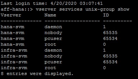
Create the “sapsys” group and list the groups to make sure addition is successful.
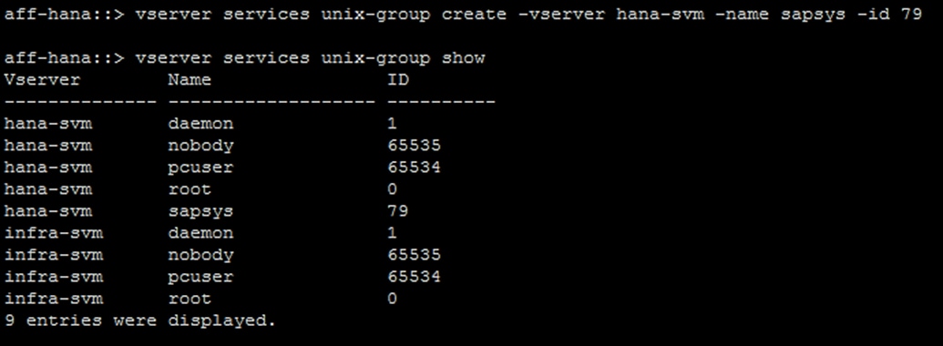
List the users available on the array and then add the planned <sid>adm users for the planned SAP HANA installations.
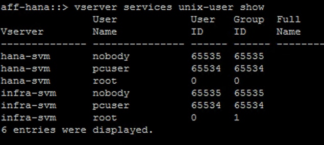
Create the needed user ids and list the groups to make sure addition is successful.
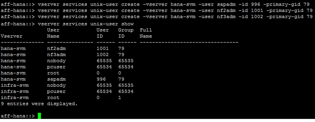
SAP HANA Data Volume Size
A default SAP HANA instance uses only one data volume per SAP HANA service. Due to the max file size limitation of the file system, NetApp recommends limiting max data volume size.
To set the following parameter automatically in the global.ini within section (persistence):
datavolume_striping = true
datavolume_striping_size_gb = 8000
This created a new data volume when the limit of 8000GB is reached.
SAP Note 240005 question 15 provides more information: https://launchpad.support.sap.com/#/notes/2400005
Introduction
AppDynamics is an Application Performance Monitoring (APM) Platform that helps you to understand and optimize the performance of your business, from its software to infrastructure to business journeys.
The AppDynamics APM Platform enables you to monitor and manage your entire application-delivery ecosystem, from the mobile app or browser client request through your network, backend databases and application servers and more. AppDynamics APM gives you a single view across your application landscape, letting you quickly navigate from the global perspective of your distributed application right down to the call graphs or exception reports generated on individual hosts.
AppDynamics has an agent-based architecture. Once our agents are installed it gives you a dynamic flow map or topography of your application. It uses the concept of traffic lights to indicate the health of your application (green is good, yellow is slow and red indicates potential issues) with dynamic baselining. AppDynamics measures application performance based on business transactions which essentially are the key functionality of the application. When the application deviates from the baseline AppDynamics captures and provides deeper diagnostic information to help be more proactive in troubleshooting and reduce the MTTR (mean time to resolution).
SAP Landscape Monitoring
AppDynamics has a one of its kind ABAP agent for monitoring SAP ABAP systems. We have comprehensive coverage of the SAP landscape with our ABAP, Java, .net and Server visibility agents. In addition, Datavard Insights extends the AppDynamics for SAP solution with system-level monitoring for the overall SAP systems and SAP HANA databases. While AppDynamics agents provides transaction-level visibility, Datavard Insights collects performance metrics, logs and events, including processes outside of the user business transactions, such as background jobs or IDocs processing.
The complex and proprietary nature of SAP applications makes it difficult to diagnose issues. AppDynamics allows enterprises to instrument SAP applications, monitor performance, and understand the root cause of performance bottlenecks.
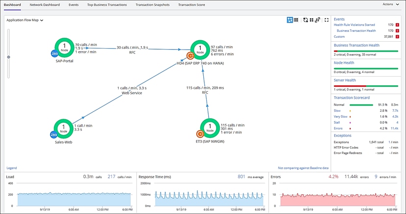
Trial Registration
To register for the trial, follow these steps:
1. Connect to https://www.appdynamics.com/free-trial/.
2. Provide the details to sign up for a free trial utilizing an AppDynamics SaaS controller.
3. Once the AppDynamics SaaS Controller has been provisioned, you will receive an email with the information you need for you to login to the Controller.
4. You can download the Java Agent and the Server Visibility Agent directly from the Controller.
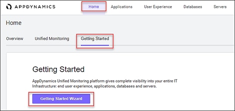
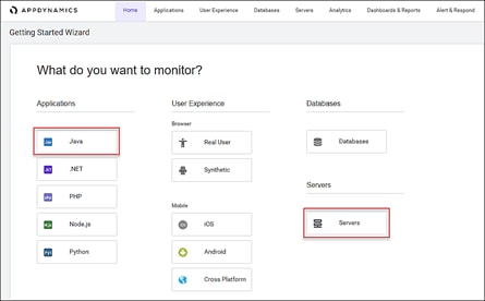
5. You can use the email and password you provided to sign up for the trial to login to the agent download site at the URL listed below and download the ABAP Agent:
https://download.appdynamics.com
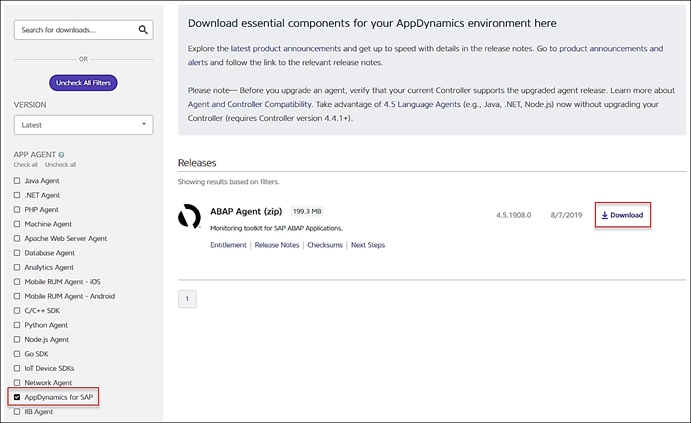
Agent Installation
AppDynamics has several types of agents to monitor different language applications to user Experience to Infrastructure monitoring. Based on the SAP landscape and the underlying technology of the SAP systems the agents are installed.
The most frequently installed agents are:
1. Java Agent - For Java based SAP Systems
2. ABAP Agent - For ABAP based SAP systems
3. Server Visibility Agent - Provides extended hardware metrics and Service Availability Monitoring
Prerequisites
Click this link to verify the supported SAP environments:
https://docs.appdynamics.com/display/SAP/SAP+Supported+Environments
Java Agent Installation
The Java Agent must be installed on SAP Java application servers (for example, Enterprise Portal and PO application servers).
The high-level steps for installing the Java Agent are listed below:
1. Ensure you are logged into the host server as the appropriate <SID>adm OS user.
2. Create the permanent installation directory for the agent.
3. Unzip the file in the permanent directory (such as /usr/sap/appdyn/app).
4. Change the permissions on the contents of the agents' installation directory to give full read/write privileges at the owner and group levels.
5. Edit the configuration file in the agent installation directory to configure the agent to connect to the controller, provide the identity of the JVM, and so on.
Configuring AppDynamics Java Agent in SAP
8. Restart the SAP JVM for the settings to take effect.
9. Validate the Java Agent is reporting to the controller by logging into the controller UI.
For detailed information, go to: Install the AppDynamics Java Agent
ABAP Agent Installation
The ABAP Agent needs to be installed on the SAP servers utilizing the ABAP stack.
There are 4 primary steps to perform, each with secondary steps involved. The four primary steps are:
1. Copy and unzip the ABAP Agent.
2. Import the ABAP Agent Transports.
3. Configure ABAP Agent and Install HTTP SDK.
4. Activate Datavard Insight Collectors.
Copy and Unzip ABAP Agent
The high-level steps to copy and unzip the ABAP Agent are listed below:
1. Ensure you are logged into the host server as the appropriate <SID>adm OS user.
2. Copy the agent binary to a temporary directory on the server.
3. Unzip the file into a temporary directory.
4. Change the permissions on the contents of the agents' installation directory to give full read/write privileges at the owner and group levels.
Import the ABAP Agent Transports
![]() There are different versions of data files and cofiles within the ABAP agents’ unzipped directory structure. The specific location of the appropriate files in the agents’ directory structure to use will depend on the version of NetWeaver in use. For more information, go to: Install on SAP NetWeaver Systems
There are different versions of data files and cofiles within the ABAP agents’ unzipped directory structure. The specific location of the appropriate files in the agents’ directory structure to use will depend on the version of NetWeaver in use. For more information, go to: Install on SAP NetWeaver Systems
The high-level steps to import the ABAP agent transports are listed below:
1. The ABAP Agents data files and cofiles should be copied from the temporary directories where they were unzipped over to the appropriate transport directories for the SAP module in question.
For example, for ECC we would copy the transports to "/usr/sap/trans/ECC2/cofiles" and "/usr/sap/trans/ECC2/data", respectively
2. Set the permissions on the cofiles and data files to allow read/write access at the owner and group levels.
3. Log into the SAP system, execute transaction STMS:
a. Go to the import queue of the system where you want to install the ABAP agent
b. Select "Extras > Other Requests > Add" from the menu bar and add the vendor transports to the import queue one at a time
4. Import the transports in the appropriate order.
The import order of the transports is specified in the “readme.txt” file of the ABAP Agent subdirectory that is specific to the version of NetWeaver in use
For more information, go to: Install on SAP NetWeaver Systems
Make sure that when selecting the "Execution" tab in the "Import Transport Request" pop-up dialog box to select the option "Synchronous". When selecting the "Options" tab, put a checkmark next to "Ignore Invalid Component Version".
Configure ABAP Agent / Install HTTP SDK
![]() The steps below assume that your Linux hosts have glibc 2.5+ installed to allow for the automatic HTTP SDK installation. For more information, see the following links: Supported SAP Operating Systems and Installing HTTP SDK Automatically.
The steps below assume that your Linux hosts have glibc 2.5+ installed to allow for the automatic HTTP SDK installation. For more information, see the following links: Supported SAP Operating Systems and Installing HTTP SDK Automatically.
The high-level steps to configure the ABAP agent and install the HTTP SDK are listed below:
1. Log into the SAP system and execute transaction "/DVD/APPD_CUST".
2. Switch to edit mode.
3. Fill in the fields on the screen to configure the agent to connect to the controller, SDK settings, and Analytics API settings..
4. Click Activate integration.
5. Click SDK Installation. This will take you to the "AppDynamics HTTP SDK Installation Manager" screen.
6. Select Edit > Change Directory.
a. Enter the path that was used for the agents' permanent base install directory (such as /usr/sap/appdyn) in the field displayed in the pop-up dialog box shown below, and then click OK.
b. Click Install SDK.
c. Click the green checkmark to exit the screen and return to the AppDynamics settings screen.
d. Click Status. This will take you to the AppDynamics status check screen.
e. Click Start to start the HTTP SDK proxy on each SAP app server.
Activate Datavard Insight Collectors
Datavard Insights collect detailed performance data for an SAP system. It uses collector jobs that run as periodic background processes in the SAP system. These jobs must be scheduled to run.
Please refer to the following links for the related documentation:
Performance Collector Settings
Mapping Between AppDynamics Metrics and Datavard Insights KPIs
Server Visibility Agent Installation
The Server Visibility Agent must be installed on every application server and central services server that will be monitored.
The high-level steps for installing the Server Visibility agent are listed below:
1. Ensure you are logged into the host server as the appropriate <SID>adm OS user.
2. Create the permanent installation directory for the agent.
3. Unzip the file in the permanent directory (such as /usr/sap/appdyn/machine).
4. Change the permissions on the contents of the agents' installation directory to give full read/write privileges at the owner and group levels.
5. Edit the configuration files in the agent installation directory to configure the agent to connect to the controller, provide the identity of the host, and so on.
6. Start the server visibility agent with the script provided in the agents’ bin directory.
7. Validate the server visibility is reporting to the controller by logging into the controller UI.
Pramod Ramamurthy, Technical Marketing Engineer, Cisco Systems, Inc.
Pramod is a Technical Marketing Engineer with Cisco UCS Solutions and Performance Group. Pramod has more than 15 years of experience in the IT industry focusing on SAP technologies. Pramod is currently focusing on the Converged Infrastructure Solutions design, validation and associated collaterals build for SAP HANA.
Marco Schoen, Technical Marketing Engineer, NetApp, Inc.
Marco is a Technical Marketing Engineer with NetApp and has over 20 years of experience in the IT industry focusing on SAP technologies. His specialization areas include SAP NetWeaver Basis technology and SAP HANA. He is currently focusing on the SAP HANA infrastructure design, validation and certification on NetApp Storage solutions and products including various server technologies.
Acknowledgements
For their support and contribution to the design, validation, and creation of this Cisco Validated Design, we would like to thank:
· Shailendra Mruthunjaya, Cisco Systems, Inc.