FlexPod Datacenter for SAP Solution with Cisco ACI, Cisco UCS Manager 4.0, and NetApp AFF A–Series Design Guide
Available Languages
Bias-Free Language
The documentation set for this product strives to use bias-free language. For the purposes of this documentation set, bias-free is defined as language that does not imply discrimination based on age, disability, gender, racial identity, ethnic identity, sexual orientation, socioeconomic status, and intersectionality. Exceptions may be present in the documentation due to language that is hardcoded in the user interfaces of the product software, language used based on RFP documentation, or language that is used by a referenced third-party product. Learn more about how Cisco is using Inclusive Language.
- US/Canada 800-553-2447
- Worldwide Support Phone Numbers
- All Tools
 Feedback
 Feedback

FlexPod Datacenter for SAP Solution with Cisco ACI, Cisco UCS Manager 4.0, and NetApp AFF A–Series Design Guide
Published: April 2020
About the Cisco Validated Design Program
The Cisco Validated Design (CVD) program consists of systems and solutions designed, tested, and documented to facilitate faster, more reliable, and more predictable customer deployments. For more information, go to:
http://www.cisco.com/go/designzone.
ALL DESIGNS, SPECIFICATIONS, STATEMENTS, INFORMATION, AND RECOMMENDATIONS (COLLECTIVELY, "DESIGNS") IN THIS MANUAL ARE PRESENTED "AS IS," WITH ALL FAULTS. CISCO AND ITS SUPPLIERS DISCLAIM ALL WARRANTIES, INCLUDING, WITHOUT LIMITATION, THE WARRANTY OF MERCHANTABILITY, FITNESS FOR A PARTICULAR PURPOSE AND NONINFRINGEMENT OR ARISING FROM A COURSE OF DEALING, USAGE, OR TRADE PRACTICE. IN NO EVENT SHALL CISCO OR ITS SUPPLIERS BE LIABLE FOR ANY INDIRECT, SPECIAL, CONSEQUENTIAL, OR INCIDENTAL DAMAGES, INCLUDING, WITHOUT LIMITATION, LOST PROFITS OR LOSS OR DAMAGE TO DATA ARISING OUT OF THE USE OR INABILITY TO USE THE DESIGNS, EVEN IF CISCO OR ITS SUPPLIERS HAVE BEEN ADVISED OF THE POSSIBILITY OF SUCH DAMAGES.
THE DESIGNS ARE SUBJECT TO CHANGE WITHOUT NOTICE. USERS ARE SOLELY RESPONSIBLE FOR THEIR APPLICATION OF THE DESIGNS. THE DESIGNS DO NOT CONSTITUTE THE TECHNICAL OR OTHER PROFESSIONAL ADVICE OF CISCO, ITS SUPPLIERS OR PARTNERS. USERS SHOULD CONSULT THEIR OWN TECHNICAL ADVISORS BEFORE IMPLEMENTING THE DESIGNS. RESULTS MAY VARY DEPENDING ON FACTORS NOT TESTED BY CISCO.
CCDE, CCENT, Cisco Eos, Cisco Lumin, Cisco Nexus, Cisco StadiumVision, Cisco TelePresence, Cisco WebEx, the Cisco logo, DCE, and Welcome to the Human Network are trademarks; Changing the Way We Work, Live, Play, and Learn and Cisco Store are service marks; and Access Registrar, Aironet, AsyncOS, Bringing the Meeting To You, Catalyst, CCDA, CCDP, CCIE, CCIP, CCNA, CCNP, CCSP, CCVP, Cisco, the Cisco Certified Internetwork Expert logo, Cisco IOS, Cisco Press, Cisco Systems, Cisco Systems Capital, the Cisco Systems logo, Cisco Unified Computing System (Cisco UCS), Cisco UCS B-Series Blade Servers, Cisco UCS C-Series Rack Servers, Cisco UCS S-Series Storage Servers, Cisco UCS Manager, Cisco UCS Management Software, Cisco Unified Fabric, Cisco Application Centric Infrastructure, Cisco Nexus 9000 Series, Cisco Nexus 7000 Series. Cisco Prime Data Center Network Manager, Cisco NX-OS Software, Cisco MDS Series, Cisco Unity, Collaboration Without Limitation, EtherFast, EtherSwitch, Event Center, Fast Step, Follow Me Browsing, FormShare, GigaDrive, HomeLink, Internet Quotient, IOS, iPhone, iQuick Study, LightStream, Linksys, MediaTone, MeetingPlace, MeetingPlace Chime Sound, MGX, Networkers, Networking Academy, Network Registrar, PCNow, PIX, PowerPanels, ProConnect, ScriptShare, SenderBase, SMARTnet, Spectrum Expert, StackWise, The Fastest Way to Increase Your Internet Quotient, TransPath, WebEx, and the WebEx logo are registered trademarks of Cisco Systems, Inc. and/or its affiliates in the United States and certain other countries.
All other trademarks mentioned in this document or website are the property of their respective owners. The use of the word partner does not imply a partnership relationship between Cisco and any other company. (0809R)
© 2020 Cisco Systems, Inc. All rights reserved.
Table of Contents
Cisco Application Centric Infrastructure (ACI)
Cisco Unified Computing System
Cisco UCS 6454 Fabric Interconnects
Cisco UCS 2408 Fabric Extender
Cisco UCS 1400 Series Virtual Interface Cards (VICs)
Cisco UCS 5108 Blade Server Chassis
Cisco UCS B200 M5 Blade Servers
Cisco UCS VICs for Cisco UCS B-Series Blade Servers
Cisco UCS VICs For Cisco UCS C-Series Rack Servers
SAP HANA Data Protection with SnapCenter
SAP HANA Disaster Recovery with Asynchronous Storage Replication
High-level architecture description
SAP application monitoring with AppDynamics
Connectivity design – compute layer
Connectivity Design – storage layer
Connectivity design – network layer
ACI fabric connectivity design
ACI fabric design – access policies
Fabric access design – access policies (VLAN pools) and VLAN design
Fabric access design – access policies (ACI domains)
Fabric access design – access policies (Attachable Entity Profile)
ACI fabric design – tenant, EPGS, application profiles, bridge domains and contracts
SAP HANA system implementation options
Single SAP HANA system on a single server: Single-host (bare metal or virtualized)
Single SAP HANA system on multiple servers: Multi-host
Multiple SAP HANA systems: Single-host (bare metal or virtualized)
Multiple SAP HANA systems: Multi-host (bare metal or virtualized)
Hardware requirements for the SAP HANA database
Validated hardware and software
Cisco Validated Designs (CVDs) consist of systems and solutions that are designed, tested, and documented to facilitate and improve customer deployments. These designs incorporate a wide range of technologies and products into a portfolio of solutions that have been developed to address the business needs of our customers and to guide them from design to deployment.
Cisco and NetApp have partnered to deliver a series of FlexPod solutions that enable strategic data center platforms. FlexPod solution delivers an integrated architecture that incorporates compute, storage, and network design best practices thereby minimizing IT risks by validating the integrated architecture to ensure compatibility between various components. The solution also addresses IT pain points by providing documented design guidance, deployment guidance and support that can be used in various stages (planning, designing and implementation) of a deployment.
This document describes Cisco ACI integrated FlexPod® solution as a validated approach for deploying SAP HANA® Tailored Data Center Integration (TDI) environments. This validated design provides guidelines and a framework for implementing SAP HANA with best practices from Cisco and NetApp.
The recommended solution architecture is built on the Cisco Unified Computing System (Cisco UCS) using a unified software release to support Cisco UCS hardware platforms that include the following components:
· Cisco UCS B-Series blade servers and Cisco UCS C-Series rack servers configurable with Intel Optane Data Center Persistent Memory Module (DCPMM) option
· Cisco UCS 6400 series Fabric Interconnects
· Cisco Nexus 9000 Series Leaf and Spine switches
· NetApp All Flash series storage arrays
Additionally, this guide provides validations for both Red Hat Enterprise Linux and SUSE Linux Enterprise Server for SAP HANA.
Introduction
Industry trends indicate a vast data center transformation toward shared infrastructure and cloud computing. Business agility requires application agility, so IT teams must provision applications quickly and resources must scale up (and out) as needed.
FlexPod Datacenter is a best practice data center architecture that was designed and validated by Cisco and NetApp to meet the needs of enterprise customers and service providers. It is built on NetApp AFF enterprise storage, the Cisco UCS, and the Cisco Nexus family of switches. These components combine to create management synergy across a business’s IT infrastructure. FlexPod Datacenter has been proven to be the optimal platform for a wide variety of workloads, including bare metal and virtualized systems, which enables enterprises to standardize their IT infrastructure.
Audience
The audience for this document includes sales engineers, field consultants, professional services specialists, IT managers, partner engineers, and customers who want to take advantage of an infrastructure built to deliver IT efficiency and enable IT innovation.
Purpose of this Document
This document provides the design principles for the Cisco Validated Design for SAP, focusing on the SAP HANA workload solution with NetApp AFF A300 array, Cisco UCS Blade Servers, and Cisco Nexus 9000 Series switches in Cisco ACI mode.
What’s New in this Release?
This primary design for FlexPod Datacenter for SAP Solution has been updated to include the latest Cisco and NetApp hardware and software, includes the following:
· Support for Cisco ACI 4.2(3l)
· Support for the Cisco UCS 4.0(4g) unified software release, Cisco UCS B480 M5 servers, Cisco UCS B200 M5 servers with 2nd Generation Intel Xeon Scalable Processors, and Cisco 1400 Series Virtual Interface Cards (VICs). As well as Cisco UCS C220, C240 and C480 M5 Rack-Mount Servers.
· Support for the latest Cisco UCS 6454 Fabric Interconnects
· Support for the latest Cisco UCS 2408 Fabric Extender
· Validation with Nexus 9300 40/100 GE switches
· Support for the latest release of NetApp ONTAP® 9.6 storage software
· Support for NFS v4.1
· Support for NetApp SnapCenter® 4.3
· NFS and iSCSI storage design
FlexPod is a best practice datacenter architecture that is based on the following components:
· Cisco Unified Computing System (Cisco UCS)
· Cisco Nexus Switches
· Cisco MDS Switches
· NetApp AFF Storage Systems
Figure 1 FlexPod component families
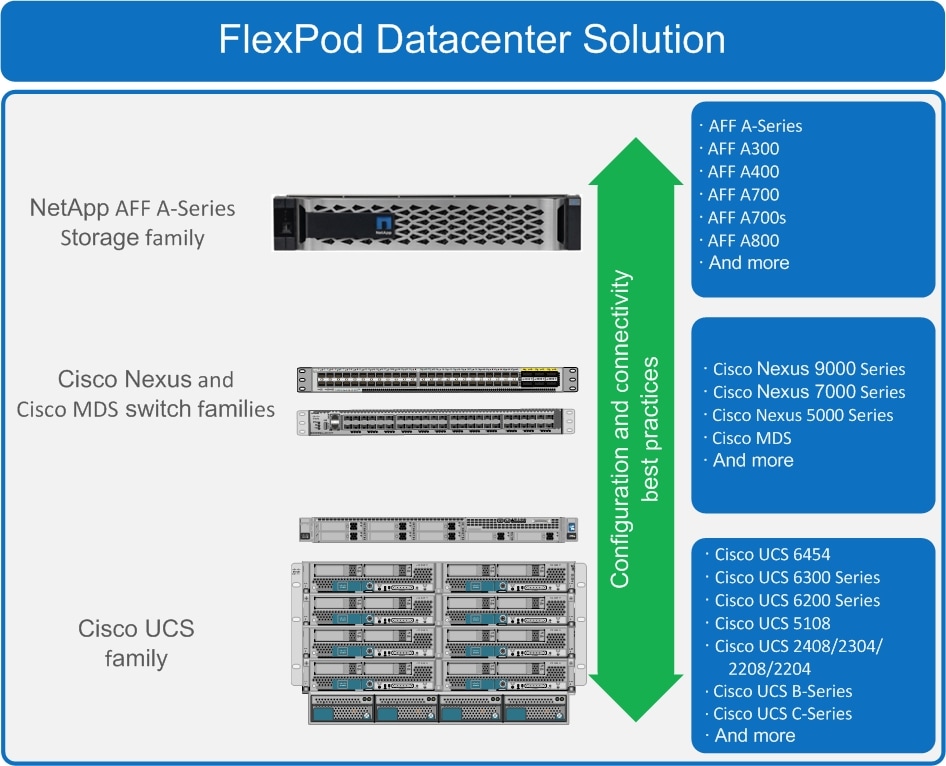
These components are connected and configured according to the combined best practices of both Cisco and NetApp to provide an ideal platform for running a variety of enterprise workloads with confidence. FlexPod can be scaled up for greater performance and capacity by adding compute, network, or storage resources individually as needed. It can also be scaled out for environments that require multiple consistent deployments, such as by rolling out of additional FlexPod stacks. The reference architecture explained in this document uses the Cisco Nexus 9000 for the network switching element.
One of the key benefits of FlexPod is its ability to maintain consistency during scaling. Each of the component families shown (Cisco UCS, Cisco Nexus, and NetApp AFF) offers platform and resource options to scale the infrastructure up or down, while still supporting the same features and functionality that are required for the configuration and connectivity best practices of FlexPod.
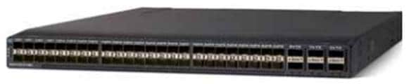
Cisco Nexus
Cisco Nexus series switches provide an Ethernet switching fabric for communications between the Cisco UCS, NetApp storage controllers, and the rest of a customer’s network. There are many factors to consider when choosing the main data switch in this type of architecture to support both the scale and the protocols required for the resulting applications. The validation for this deployment leverages the Cisco Nexus 9300 series switches, which deliver high performance 100/40GbE ports, density, low latency, and exceptional power efficiency in a broad range of compact form factors.
The Cisco Nexus 9000 family of switches supports two modes of operation: NxOS standalone mode and Application Centric Infrastructure (ACI) fabric mode. In standalone mode, the switch performs as a typical Nexus switch with increased port density, low latency and 40Gb connectivity. Cisco Nexus 9000 based FlexPod design with Cisco ACI consists of Cisco Nexus 9500 and 9300 based spine/leaf switching architecture controlled using a cluster of three Application Policy Infrastructure Controllers (APICs).
Many of the recent single-site FlexPod designs also use this switch due to the advanced feature set and the ability to support Application Centric Infrastructure (ACI) mode. When leveraging ACI fabric mode, the Nexus 9000 series switches are deployed in a spine-leaf architecture. The design guide captures both reference architectures: one with Nexus Switches in the standalone mode and another with ACI mode.
For more information, go to http://www.cisco.com/c/en/us/products/switches/nexus-9000-series-switches/index.html.
Cisco Application Centric Infrastructure (ACI)
Cisco Nexus 9000 Series Switches are the foundation of the ACI architecture and provide the network fabric. A new operating system is used by Cisco Nexus 9000 switches running in ACI mode. The switches are then coupled with a centralized controller, the APIC, and its open API. The APIC is the unifying point of automation, telemetry, and management for the ACI fabric, helping to enable an application policy model approach to the datacenter.
Cisco ACI delivers a resilient fabric to today's dynamic applications. ACI leverages a network fabric that employs industry proven protocols coupled with innovative technologies to create a flexible, scalable, and highly available architecture of low-latency and high-bandwidth links. This fabric delivers application instantiations using profiles that house the requisite characteristics to enable end-to-end connectivity.
The ACI fabric is designed to support the industry trends of management automation, programmatic policies, and dynamic workload provisioning. The ACI fabric accomplishes this with a combination of hardware, policy-based control systems, and closely coupled software to provide advantages not possible in other architectures.
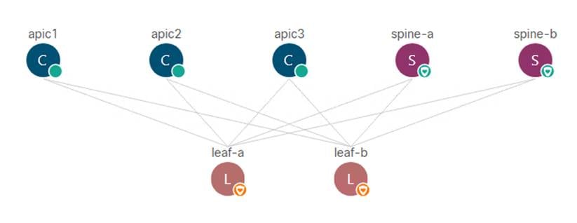
The Cisco ACI Fabric consists of three major components:
· Application Policy Infrastructure Controller (APIC)
· Spine switches
· Leaf switches
The ACI switching architecture uses a leaf-and-spine topology, in which each leaf switch is connected to every spine switch in the network, with no interconnection between leaf switches or spine switches. Each leaf and spine switch is connected with one or more 40 Gigabit Ethernet links or with 100 Gigabit links. Each APIC appliance should connect to two leaf switches for resiliency purpose.
Figure 2 Cisco ACI Fabric architecture
ACI components
· Cisco Application Policy Infrastructure Controller
The Cisco Application Policy Infrastructure Controller (APIC) is the unifying point of automation and management for the ACI fabric. The Cisco APIC provides centralized access to all fabric information, optimizes the application lifecycle for scale and performance, and supports flexible application provisioning across physical and virtual resources. Some of the key benefits of Cisco APIC are:
- Centralized application-level policy engine for physical, virtual, and cloud infrastructures
- Detailed visibility, telemetry, and health scores by application and by tenant
- Designed around open standards and open APIs
- Robust implementation of multi-tenant security, quality of service (QoS), and high availability
- Integration with management systems such as VMware, Microsoft, and OpenStack
The software controller, APIC, is delivered as an appliance and three or more such appliances form a cluster for high availability and enhanced performance. The controller is a physical appliance based on a Cisco UCS® rack server with two 10 Gigabit Ethernet interfaces for connectivity to the leaf switches. The APIC is also equipped with 1 Gigabit Ethernet interfaces for out-of-band management. Controllers can be configured with 10GBASE-T or SFP+ Network Interface Cards (NICs), and this configuration must match the physical format supported by the leaf. In other words, if controllers are configured with 10GBASE-T, they have to be connected to a Cisco ACI leaf with 10GBASE-T ports.
APIC is responsible for all tasks enabling traffic transport including:
- Fabric activation
- Switch firmware management
- Network policy configuration and instantiation
Although the APIC acts as the centralized point of configuration for policy and network connectivity, it is never in line with the data path or the forwarding topology. The fabric can still forward traffic even when communication with the APIC is lost.
APIC provides both a command line interface (CLI) and graphical user interface (GUI) to configure and control the ACI fabric. APIC also provides a northbound API through XML and JavaScript Object Notation (JSON) and an open source southbound API.
For more information on Cisco APIC, go to: http://www.cisco.com/c/en/us/products/cloud-systems-management/application-policy-infrastructure-controller-apic/index.html
· Leaf switches
In Cisco ACI, all workloads connect to leaf switches. A leaf switch can be a fixed form Nexus 9300 series or a modular Nexus 9500 series switch that provides physical server and storage connectivity as well as enforces ACI policies. The latest Cisco ACI fixed form factor leaf nodes allow connectivity up to 25 and 40 Gbps to the server and uplinks of 100 Gbps to the spine. There are a number of leaf switch choices that differ based on functions like port speed, medium type, multicast routing support, scale of endpoints, and so on.
For a summary of the available leaf switch options, refer to the Cisco ACI Best Practices Guide.
· Spine switches
The Cisco ACI fabric forwards traffic primarily based on host lookups. A mapping database stores the information about the leaf switch on which each IP address resides. This information is stored in the fabric cards of the spine switches. All known endpoints in the fabric are programmed in the spine switches. The spine models also differ in the number of endpoints supported in the mapping database, which depends on the type and number of fabric modules installed.
For a summary of available spine switch options, refer to the Cisco ACI Best Practices Guide.
Cisco Unified Computing System
Cisco Unified Computing System (Cisco UCS) is a next-generation data center platform that integrates computing, networking, storage access, and virtualization resources into a cohesive system designed to reduce total cost of ownership and increase business agility. The system integrates a low-latency, lossless 10-100 Gigabit Ethernet unified network fabric with enterprise-class, x86-architecture servers. The system is an integrated, scalable, multi-chassis platform with a unified management domain for managing all resources.
Cisco Unified Computing System consists of the following subsystems:
· Compute - The compute piece of the system incorporates servers based on the 2nd Generation Intel® Xeon® Scalable processors. Servers are available in blade and rack form factor, managed by Cisco UCS Manager.
· Network - The integrated network fabric in the system provides a low-latency, lossless, 10/25/40/100 Gbps Ethernet fabric. Networks for LAN, SAN and management access are consolidated within the fabric. The unified fabric uses the innovative Single Connect technology to lowers costs by reducing the number of network adapters, switches, and cables. This in turn lowers the power and cooling needs of the system.
· Virtualization - The system unleashes the full potential of virtualization by enhancing the scalability, performance, and operational control of virtual environments. Cisco security, policy enforcement, and diagnostic features are now extended into virtual environments to support evolving business needs.
· Storage access – Cisco UCS system provides consolidated access to both SAN storage and Network Attached Storage over the unified fabric. This provides customers with storage choices and investment protection. Also, the server administrators can pre-assign storage-access policies to storage resources, for simplified storage connectivity and management leading to increased productivity.
· Management - The system uniquely integrates compute, network and storage access subsystems, enabling it to be managed as a single entity through Cisco UCS Manager software. Cisco UCS Manager increases IT staff productivity by enabling storage, network, and server administrators to collaborate on Service Profiles that define the desired physical configurations and infrastructure policies for applications. Service Profiles increase business agility by enabling IT to automate and provision resources in minutes instead of days.
Cisco UCS Differentiators
Cisco Unified Computing System is revolutionizing the way servers are managed in the datacenter. The following are the unique differentiators of Cisco Unified Computing System and Cisco UCS Manager:
· Embedded Management — In Cisco UCS, the servers are managed by the embedded firmware in the Fabric Interconnects, eliminating need for any external physical or virtual devices to manage the servers.
· Unified Fabric — In Cisco UCS, from blade server chassis or rack servers to FI, there is a single Ethernet cable used for LAN, SAN and management traffic. This converged I/O results in reduced cables, SFPs and adapters – reducing capital and operational expenses of the overall solution.
· Auto Discovery — By simply inserting the blade server in the chassis or connecting the rack server to the fabric interconnect, discovery and inventory of compute resources occurs automatically without any management intervention. The combination of unified fabric and auto-discovery enables the wire-once architecture of Cisco UCS, where compute capability of Cisco UCS can be extended easily while keeping the existing external connectivity to LAN, SAN and management networks.
· Policy Based Resource Classification — Once a compute resource is discovered by Cisco UCS Manager, it can be automatically classified to a given resource pool based on policies defined. This capability is useful in multi-tenant cloud computing. This CVD showcases the policy-based resource classification of Cisco UCS Manager.
· Combined Rack and Blade Server Management — Cisco UCS Manager can manage Cisco UCS B-series blade servers and Cisco UCS C-series rack servers under the same Cisco UCS domain. This feature, along with stateless computing makes compute resources truly hardware form factor agnostic.
· Model based Management Architecture — The Cisco UCS Manager architecture and management database is model based and data driven. An open XML API is provided to operate on the management model. This enables easy and scalable integration of Cisco UCS Manager with other management systems.
· Policies, Pools, Templates — The management approach in Cisco UCS Manager is based on defining policies, pools and templates, instead of cluttered configuration, which enables a simple, loosely coupled, data driven approach in managing compute, network and storage resources.
· Loose Referential Integrity — In Cisco UCS Manager, a service profile, port profile or policies can refer to other policies or logical resources with loose referential integrity. A referred policy cannot exist at the time of authoring the referring policy or a referred policy can be deleted even though other policies are referring to it. This provides different subject matter experts to work independently from each other. This provides great flexibility where different experts from different domains, such as network, storage, security, server and virtualization work together to accomplish a complex task.
· Policy Resolution — In Cisco UCS Manager, a tree structure of organizational unit hierarchy can be created that mimics the real-life tenants and/or organization relationships. Various policies, pools and templates can be defined at different levels of organization hierarchy. A policy referring to another policy by name is resolved in the organizational hierarchy with closest policy match. If no policy with specific name is found in the hierarchy of the root organization, then the special policy named “default” is searched. This policy resolution practice enables automation friendly management APIs and provides great flexibility to owners of different organizations.
· Service Profiles and Stateless Computing — A service profile is a logical representation of a server, carrying its various identities and policies. This logical server can be assigned to any physical compute resource as far as it meets the resource requirements. Stateless computing enables procurement of a server within minutes, which used to take days in legacy server management systems.
· Built-in Multi-Tenancy Support — The combination of policies, pools and templates, loose referential integrity, policy resolution in the organizational hierarchy and a service profiles-based approach to compute resources makes Cisco UCS Manager inherently friendly to multi-tenant environments typically observed in private and public clouds.
· Extended Memory — The enterprise-class Cisco UCS Blade server extends the capabilities of Cisco’s Unified Computing System portfolio in a half-width blade form factor. It harnesses the power of the latest Intel® Xeon® Scalable Series processor family CPUs and Intel® Optane DC Persistent Memory (DCPMM) with up to 18TB of RAM (using 256GB DDR4 DIMMs and 512GB DCPMM).
· Simplified QoS — Even though Fibre Channel and Ethernet are converged in the Cisco UCS fabric, built-in support for QoS and lossless Ethernet makes it seamless. Network Quality of Service (QoS) is simplified in Cisco UCS Manager by representing all system classes in one GUI panel.
Cisco UCS Manager
Cisco UCS Manager (UCSM) provides unified, integrated management for all software and hardware components in Cisco UCS. Using Cisco Single Connect technology, it manages, controls, and administers multiple chassis for thousands of virtual machines. Administrators use the software to manage the entire Cisco Unified Computing System as a single logical entity through an intuitive graphical user interface (GUI), a command line interface (CLI), or a through a robust application programming interface (API).
Cisco UCS Manager is embedded into the Cisco UCS Fabric Interconnects and provides a unified management interface that integrates server, network, and storage. Cisco UCS Manger performs auto-discovery to detect inventory, manage, and provision system components that are added or changed. It offers comprehensive set of XML API for third party integration, exposes thousands of integration points and facilitates custom development for automation, orchestration, and to achieve new levels of system visibility and control.
Cisco UCS™ Manager, Release 4.0 provides unified, embedded management of all software and hardware components of the Cisco Unified Computing System™ (Cisco UCS) across multiple chassis and Cisco UCS servers. Cisco UCS Manager, Release 4.0 is a unified software release for all supported Cisco UCS hardware platforms. Release 4.0 enables support for UCS 6454 Fabric Interconnects, VIC 1400 series adapter cards on Cisco UCS M5 servers and Second Generation Intel® Xeon® Scalable processor refresh and Intel® Optane™ Data Center persistent memory modules on Cisco UCS Intel-based M5 servers.
For more information on Cisco UCSM Release 4.0 refer to the Release Notes for Cisco UCS Manager, release 4.0.
Cisco Intersight
Cisco Intersight is Cisco’s new systems management platform that delivers intuitive computing through cloud-powered intelligence. This platform offers a more intelligent management level and enables IT organizations to analyze, simplify and automate their IT environments in ways that were not possible with prior generations of tools. This capability empowers organizations to achieve significant savings in Total Cost of Ownership (TCO) and to deliver applications faster to support new business initiatives.
The Cisco UCS platform uses model-based management to provision servers and fabric automatically, regardless of form factor. Cisco Intersight works in conjunction with Cisco UCS Manager and the Cisco Integrated Management Controller (IMC). By simply associating a model-based configuration with a resource through service profiles, your IT staff can consistently align policy, server personality, and workloads. These policies can be created once and used by IT staff with minimal effort to deploy servers. The result is improved productivity and compliance and lower risk of failures due to inconsistent configuration.
Cisco Intersight will be integrated with data center, hybrid cloud platforms and services to securely deploy and manage infrastructure resources across data center and edge environments. In addition, Cisco will provide future integrations to third-party operations tools to allow customers to use their existing solutions more effectively.
Cisco Intersight monitors all Cisco UCS servers and switches in the solution and offers cloud-based, centralized management of Cisco UCS servers across all Enterprise locations and delivers unique capabilities such as:
· Integration with Cisco TAC for support and case management
· Proactive, actionable intelligence for issues and support based on telemetry data
· Compliance check through integration with Cisco Hardware Compatibility List (HCL)
· Centralized service profiles for policy-based configuration
For more information about Cisco Intersight and the different editions, go to: Cisco Intersight - SaaS Systems Management Platform.
Cisco UCS 6454 Fabric Interconnects
The Cisco UCS Fabric Interconnects provide a single point for connectivity and management for the entire system. Deployed as an active-active pair, the system’s fabric interconnects integrate all components into a single, highly available management domain controlled by Cisco UCS Manager. The fabric interconnects manage all I/O efficiently and securely at a single point, resulting in deterministic I/O latency regardless of a server or virtual machine’s topological location in the system.
The Cisco UCS Fabric Interconnect provides both network connectivity and management capabilities for the Cisco UCS system. IO modules in the blade chassis support power supply, along with fan and blade management. They also support port channeling and, thus, better use of bandwidth. The IOMs support virtualization-aware networking in conjunction with the Fabric Interconnects and Cisco Virtual Interface Cards (VIC).
The Cisco UCS 6454 Fabric Interconnect is a core part of the Cisco Unified Computing System, providing both network connectivity and management capabilities for the system. The Cisco UCS 6454 offers line-rate, low-latency, lossless 10/25/40/100 Gigabit Ethernet, Fibre Channel over Ethernet (FCoE), and 32 Gigabit Fibre Channel functions.
The Cisco UCS 6454 54-Port Fabric Interconnect is a One-Rack-Unit (1RU) 10/25/40/100 Gigabit Ethernet, FCoE and Fibre Channel switch offering up to 3.82 Tbps throughput and up to 54 ports. The switch has 28 10/25-Gbps Ethernet ports, 4 1/10/25-Gbps Ethernet ports, 6 40/100-Gbps Ethernet uplink ports and 16 unified ports that can support 10/25-Gbps Ethernet ports or 8/16/32-Gbps Fibre Channel ports. All Ethernet ports are capable of supporting FCoE.
Figure 3 Cisco UCS 6454 Fabric Interconnect
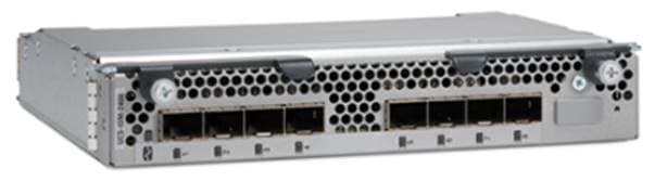
Cisco UCS 2408 Fabric Extender
The Cisco UCS 2408 connects the I/O fabric between the Cisco UCS 6454 Fabric Interconnect and the Cisco UCS 5100 Series Blade Server Chassis, enabling a lossless and deterministic converged fabric to connect all blades and chassis together. Because the fabric extender is similar to a distributed line card, it does not perform any switching and is managed as an extension of the fabric interconnects. This approach removes switching from the chassis, reducing overall infrastructure complexity and enabling Cisco UCS to scale to many chassis without multiplying the number of switches needed, reducing TCO, and allowing all chassis to be managed as a single, highly available management domain.
The Cisco UCS 2408 Fabric Extender [FEX] has eight 25-Gigabit Ethernet, FCoE-capable, Small Form-Factor Pluggable (SFP28) ports that connect the blade chassis to the fabric interconnect. Each Cisco UCS 2408 provides 10-Gigabit Ethernet ports connected through the midplane to each half-width slot in the chassis, giving it a total 32 10G interfaces to UCS blades. Typically configured in pairs for redundancy, two fabric extenders provide up to 400 Gbps of I/O from FI 6454's to 5108 chassis.
Figure 4 Cisco UCS FEX 2408
Each fabric extender connects to one Fabric Interconnect using multiple Ethernet 25Gbps links – the number of links determines the uplink I/O bandwidth through that FEX. The number of links can be 1, 2, 4 or 8. These links can be deployed as independent links (discrete Mode) or grouped together using link aggregation (port channel mode).
Figure 5 Fabric Extender to Fabric Interconnect connectivity options
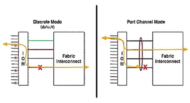
In discrete mode, each server is pinned to a FEX link going to a port on the fabric interconnect and if the link goes down, the server’s connection also goes down through the FEX link. In port channel mode, the flows from the server will be redistributed across the remaining port channel members. This is less disruptive overall and therefore port channel mode is recommended for this FlexPod design.
Cisco UCS 1400 Series Virtual Interface Cards (VICs)
Cisco VICs support Cisco SingleConnect technology, which provides an easy, intelligent, and efficient way to connect and manage computing in your data center. Cisco SingleConnect unifies LAN, SAN, and systems management into one simplified link for rack servers and blade servers. This technology reduces the number of network adapters, cables, and switches needed and radically simplifies the network, reducing complexity. Cisco VICs can support 256 Express (PCIe) virtual devices, either virtual Network Interface Cards (vNICs) or virtual Host Bus Adapters (vHBAs), with a high rate of I/O Operations Per Second (IOPS), support for lossless Ethernet, and 10/25/40/100-Gbps connection to servers. The PCIe Generation 3 x16 interface helps ensure optimal bandwidth to the host for network-intensive applications, with a redundant path to the fabric interconnect. Cisco VICs support NIC teaming with fabric failover for increased reliability and availability. In addition, it provides a policy-based, stateless, agile server infrastructure for your data center.
The Cisco VIC 1400 series is designed exclusively for the M5 generation of Cisco UCS B-Series Blade Servers and Cisco UCS C-Series Rack Servers. The adapters are capable of supporting 10/25/40/100-Gigabit Ethernet and Fibre Channel over Ethernet (FCoE). It incorporates Cisco’s next-generation Converged Network Adapter (CNA) technology and offers a comprehensive feature set, providing investment protection for future feature software releases.
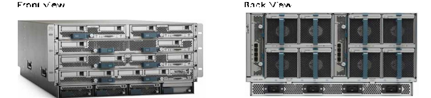
Cisco UCS 5108 Blade Server Chassis
The Cisco UCS 5108 Blade Server Chassis is a fundamental building block of the Cisco Unified Computing System, delivering a scalable and flexible blade server architecture. The Cisco UCS blade server chassis uses an innovative unified fabric with fabric-extender technology to lower TCO by reducing the number of network interface cards (NICs), host bus adapters (HBAs), switches, and cables that need to be managed, cooled, and powered. It is a 6-RU chassis that can house up to 8 x half-width or 4 x full-width Cisco UCS B-series blade servers. A passive mid-plane provides up to 80Gbps of I/O bandwidth per server slot and up to 160Gbps for two slots (full-width). The rear of the chassis contains two I/O bays to house a pair of Cisco UCS 2000 Series Fabric Extenders to enable uplink connectivity to FIs for both redundancy and bandwidth aggregation.
Figure 6 Cisco UCS 5108 Blade Server Chassis
Cisco UCS B200 M5 Blade Servers
The Cisco UCS B200 M5 Blade Server shown in Figure 7. is a half-width blade successor from the Cisco UCS B200 M4.
Figure 7 Cisco UCS B200 M5 Blade Server
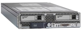
It features:
· 2nd Generation Intel® Xeon® Scalable processors with up to 28 cores per socket
· Up to 3 terabytes (TB) of DDR4 memory for improved performance
· Up to 7.5 terabytes (TB) using 12x128G DDR4 DIMMs and 12x512G Intel® Optane DCPMM nonvolatile memory technology
· Up to two NIVIDA GPUs
· Two Small-Form-Factor (SFF) drive slots
· Up to two Secure Digital (SD) cards or M.2 SATA drives
For more information about the Cisco UCS B200 M5 Blade Servers, see the Cisco UCS B200 M5 Blade Server datasheet.
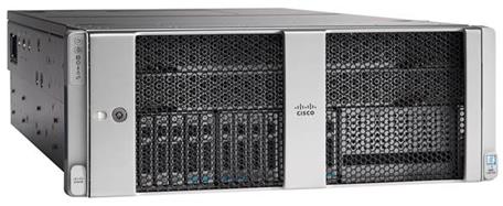
Cisco UCS B480 M5 Servers
The enterprise-class Cisco UCS B480 M5 Blade Server delivers market-leading performance, versatility, and density without compromise for memory-intensive mission-critical enterprise applications and virtualized workloads, among others. The Cisco UCS B480 M5 is a full-width blade server supported by the Cisco UCS 5108 Blade Server Chassis.
The Cisco UCS B480 M5 Blade Server offers Four Intel Xeon Scalable CPUs (up to 28 cores per socket), up to 12 TB of DDR4 memory and 18 TB using 24x256G DDR4 DIMMs and 24x512G Intel® Optane DC Persistent Memory. Five mezzanine adapters and support for up to four GPUs and Cisco UCS Virtual Interface Card (VIC) 1440 modular LAN on Motherboard (mLOM) and Cisco UCS Virtual Interface Card (VIC) 1480 is a dual-port 40-Gbps Ethernet.
Figure 8 Cisco UCS B480 M5 Blade Server

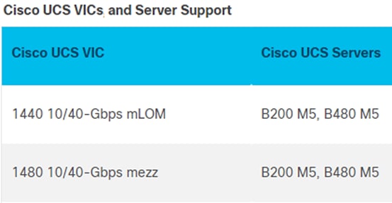
Cisco UCS VICs for Cisco UCS B-Series Blade Servers
The Cisco UCS VIC 1440 (Figure 9) is a single-port 40-Gbps or 4x10-Gbps Ethernet/FCoE capable modular LAN On Motherboard (mLOM) designed exclusively for the M5 generation of Cisco UCS B-Series Blade Servers. When used in combination with an optional port expander, the Cisco UCS VIC 1440 capabilities are enabled for two ports of 40-Gbps Ethernet. The Cisco UCS VIC 1440 enables a policy-based, stateless, agile server infrastructure that can present to the host PCIe standards-compliant interfaces that can be dynamically configured as either NICs or HBAs.
The Cisco UCS VIC 1480 (Figure 10) is a single-port 40-Gbps or 4x10-Gbps Ethernet/FCoE capable mezzanine card (mezz) designed exclusively for the M5 generation of Cisco UCS B-Series Blade Servers. The card enables a policy-based, stateless, agile server infrastructure that can present PCIe standards-compliant interfaces to the host that can be dynamically configured as either NICs or HBAs.
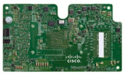

Table 1 Supported servers
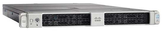
Cisco UCS C480 M5 Rack Server
The Cisco UCS C480 M5 Rack Server (Figure 11) can be deployed as a standalone server or in a Cisco UCS managed environment. When used in combination with Cisco UCS Manager, the Cisco UCS C480 M5 brings the power and automation of unified computing to enterprise applications, including Cisco SingleConnect technology, drastically reducing switching and cabling requirements. Cisco UCS Manager uses service profiles, templates, and policy-based management to enable rapid deployment and help ensure deployment consistency. It also enables end-to-end server visibility, management, and control in both virtualized and bare-metal environments.
The Cisco UCS C480 M5 is a storage- and I/O-optimized enterprise-class rack server that delivers industry-leading performance for IMDBs, Big Data analytics, Virtualization workloads and bare-metal applications.
It delivers outstanding levels of expandability and performance for standalone or Cisco UCS managed environments in a 4-rack-unit (4RU) form factor, and because of its modular design, you pay for only what you need.
The Cisco UCS C480 M5 offers these capabilities:
· Latest Intel Xeon Scalable processors with up to 28 cores per socket and support for two- or four-processor configurations
· 2933-MHz DDR4 memory and 48 DIMM slots for up to 6 TB of total memory
· 12 PCI Express (PCIe) 3.0 slots
· Six x8 full-height, full-length slots
· Six x16 full-height, full-length slots
· Flexible storage options with support up to 32 small-form-factor (SFF) 2.5-inch, SAS, SATA, and PCIe Non-Volatile Memory Express (NVMe) disk drives
· Cisco 12-Gbps SAS modular RAID controller in a dedicated slot
· Internal Secure Digital (SD) and M.2 boot options
· Dual embedded 10 Gigabit Ethernet LAN-on-motherboard (LOM) ports
Figure 11 Cisco UCS C480 M5 Rack Server
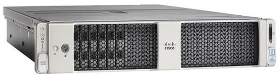
Cisco UCS C240 M5 Rack Server
The Cisco UCS C240 M5 Rack Server (Figure 12) is a 2-socket, 2RU rack server offering industry-leading performance and expandability. Cisco UCS C-Series Rack Servers can be deployed as standalone servers or as part of a Cisco UCS managed environment to take advantage of Cisco’s standards-based unified computing innovations that help reduce customers’ TCO and increase their business agility.
In response to ever increasing computing and data-intensive real-time workloads, the enterprise-class Cisco UCS C240 M5 server extends the capabilities of the Cisco UCS portfolio in a 2RU form factor. It incorporates the Intel Xeon Scalable processors, supporting up to 20 percent more cores per socket, twice the memory capacity, and five times more NVMe PCIe SSDs than the previous generation of servers. These improvements deliver significant performance and efficiency gains that will improve your application performance. The Cisco UCS C240 M5 delivers outstanding storage expandability with exceptional performance, with:
· Latest Intel Xeon Scalable CPUs with up to 28 cores per socket
· Up to 24 DDR4 DIMMs for improved performance
· Intel 3D XPoint-ready support, with built-in support for next-generation nonvolatile memory technology
· Up to 26 hot-swappable SFF 2.5-inch drives, including 2 rear hot-swappable SFF drives (up to 10 support NVMe PCIe SSDs on the NVMe-optimized chassis version), or 12 large form factor (LFF) 3.5-inch drives plus 2 rear hot-swappable SFF drives
· Support for a 12-Gbps SAS modular RAID controller in a dedicated slot, leaving the remaining PCIe Generation 3.0 slots available for other expansion cards
· Modular LOM (mLOM) slot that can be used to install a Cisco UCS VIC without consuming a PCIe slot, supporting dual 10- or 40-Gbps network connectivity
· Dual embedded Intel x550 10GBASE-T LOM ports
· Modular M.2 or SD cards that can be used for bootup
· High performance for data-intensive applications
The Cisco UCS C240 M5 Rack Server is well-suited for a wide range of enterprise workloads, including; big data and analytics, collaboration, small and medium-sized business (SMB) databases, virtualization and consolidation, storage servers and high-performance appliances.
Cisco UCS C240 M5 servers can be deployed as standalone servers or in a Cisco UCS managed environment. When used in combination with Cisco UCS Manager, the Cisco UCS C240 M5 brings the power and automation of unified computing to enterprise applications, including Cisco SingleConnect technology, drastically reducing switching and cabling requirements.
Cisco UCS Manager uses service profiles, templates, and policy-based management to enable rapid deployment and help ensure deployment consistency. If also enables end-to-end server visibility, management, and control in both virtualized and bare-metal environments.
Figure 12 Cisco UCS C240 M5 Rack Server
Cisco UCS C220 M5 Rack Server
The Cisco UCS C220 M5 Rack Server (Figure 13) is among the most versatile general-purpose enterprise infrastructure and application servers in the industry. It is a high-density 2-socket rack server that delivers industry-leading performance and efficiency for a wide range of workloads, including virtualization, collaboration, and bare-metal applications. The Cisco UCS C-Series Rack Servers can be deployed as standalone servers or as part of Cisco UCS to take advantage of Cisco’s standards-based unified computing innovations that help reduce customers’ TCO and increase their business agility.
The Cisco UCS C220 M5 server extends the capabilities of the Cisco UCS portfolio in a 1RU form factor. It incorporates the Intel Xeon Scalable processors, supporting up to 20 percent more cores per socket, twice the memory capacity, 20 percent greater storage density, and five times more PCIe NVMe SSDs than the previous generation of servers. These improvements deliver significant performance and efficiency gains that will improve your application performance. The Cisco UCS C220 M5 server delivers outstanding levels of expandability and performance in a compact package, with:
· Latest Intel Xeon Scalable CPUs with up to 28 cores per socket
· Up to 24 DDR4 DIMMs for improved performance
· Intel 3D XPoint-ready support, with built-in support for next-generation nonvolatile memory technology
· Up to 10 SFF 2.5-inch drives or 4 LFF 3.5-inch drives (77 TB of storage capacity with all NVMe PCIe SSDs)
· Support for a 12-Gbps SAS modular RAID controller in a dedicated slot, leaving the remaining PCIe Generation 3.0 slots available for other expansion cards
· mLOM slot that can be used to install a Cisco UCS VIC without consuming a PCIe slot, supporting dual 10- or 40-Gbps network connectivity
· Dual embedded Intel x550 10GBASE-T LOM ports
· High performance for data-intensive applications
The Cisco UCS C220 M5 Rack Server is well-suited for a wide range of enterprise workloads, including: Big Data and analytics, Collaboration. SMB databases, Virtualization and consolidation. Storage servers, high-performance appliances.
Cisco UCS C220 M5 servers can be deployed as standalone servers or in a Cisco UCS managed environment. When used in combination with Cisco UCS Manager, the Cisco UCS C220 M5 brings the power and automation of unified computing to enterprise applications, including Cisco SingleConnect technology, drastically reducing switching and cabling requirements.
Cisco UCS Manager uses service profiles, templates, and policy-based management to enable rapid deployment and help ensure deployment consistency. If also enables end-to-end server visibility, management, and control in both virtualized and bare-metal environments.
Figure 13 Cisco UCS C220 M5 Rack Server
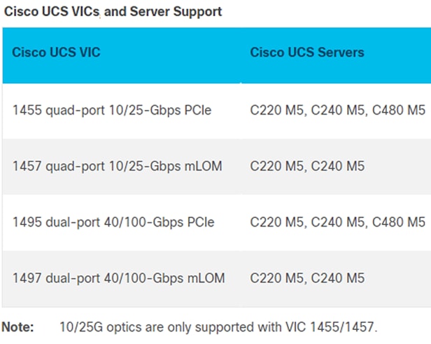
Cisco UCS VICs For Cisco UCS C-Series Rack Servers
The Cisco UCS VIC 1455 (Figure 14) is a quad-port Small Form-Factor Pluggable (SFP28) half-height PCIe card designed for the M5 generation of Cisco UCS C-Series Rack Servers. The card supports 10/25-Gbps Ethernet or FCoE.
The Cisco UCS VIC 1457 (Figure 15) is a quad-port Small Form-Factor Pluggable (SFP28) mLOM card designed for the M5 generation of Cisco UCS C-Series Rack Servers. The card supports 10/25-Gbps Ethernet or FCoE.
The Cisco VIC 1495 (Figure 16) is a dual-port Quad Small Form-Factor (QSFP28) PCIe card designed for the M5 generation of Cisco UCS C-Series Rack Servers. The card supports 40/100-Gbps Ethernet or FCoE.
The Cisco VIC 1497 (Figure 17) is a dual-port Quad Small Form-Factor (QSFP28) mLOM card designed for the M5 generation of Cisco UCS C-Series Rack Servers. The card supports 40/100-Gbps Ethernet or FCoE.
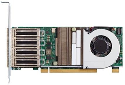
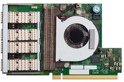
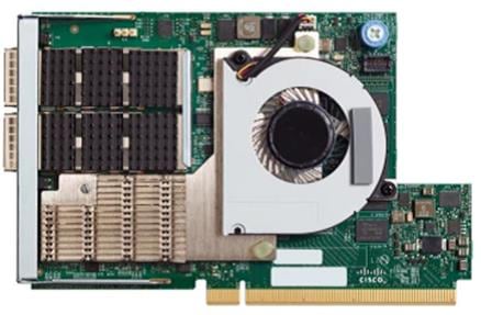
Table 2 Supported servers
NetApp AFF A300 storage
With the new NetApp® AFF A-Series controller lineup, NetApp provides industry leading performance combined with a full suite of enterprise-grade data management and data protection features.
The NetApp AFF A300 controllers provide the high-performance benefits of 40GbE and all flash SSDs, offering better performance than comparable options, while taking up less space in the rack. Combined with the disk shelf of 3.8TB disks, this solution can provide over ample horsepower and over 90TB of capacity, all while taking up only 5U of valuable rack space. This makes it an ideal controller for a shared workload converged infrastructure. As an infrastructure’s capacity or performance needs grow, the NetApp AFF A300 can increase capacity with additional storage shelves and performance by adding additional controllers to the cluster; a cluster can scale up to 24 nodes.
Figure 18 NetApp A300 front view
Figure 19 NetApp A300 rear view
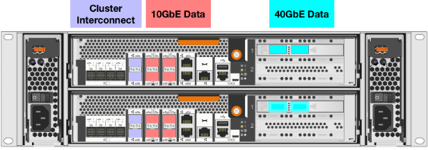
![]() The 40GbE cards are installed in the expansion slot 2 and the ports are e1a, e1e.
The 40GbE cards are installed in the expansion slot 2 and the ports are e1a, e1e.
For more information about the NetApp AFF A300 and all the AFF A-series controllers, see the AFF product page.
NetApp ONTAP 9.6
NetApp ONTAP 9.6 data management software is used with the NetApp AFF A320 all-flash storage system in this solution design. ONTAP software offers unified storage for applications that read and write data over block or file access protocol storage configurations.
ONTAP implementations can run on NetApp engineered FAS or AFF series arrays. They can also run on commodity hardware (NetApp ONTAP Select) and in private, public, or hybrid clouds (NetApp Cloud Volumes ONTAP and the NetApp Cloud Volumes Service). Specialized implementations offer best-in-class converged infrastructure, featured here as part of the FlexPod Datacenter solution, or with access to third-party storage arrays (NetApp FlexArray® virtualization).
Together these implementations form the basic framework of a data fabric supported by NetApp with a common software-defined approach to data management and fast and efficient replication across systems. FlexPod and ONTAP can serve as the foundation for both hybrid-cloud and private-cloud designs.
The following sections provide an overview of ONTAP 9.6 as an industry leading data management software architected on the principles of software-defined storage.
For more information about all the capabilities of ONTAP data management software, go to: ONTAP Data Management Software.
NetApp storage virtual machine
A NetApp ONTAP cluster serves data through at least one, and potentially multiple, storage virtual machines (SVMs). An SVM is a logical abstraction that represents the set of physical resources of the cluster. SVMs enable multitenancy with strict separation of data for each tenant. Data volumes and network LIFs are created and assigned to an SVM and can reside on any node in the cluster that the SVM has access to.
An SVM can own resources on multiple nodes concurrently, and those resources can be moved non-disruptively from one node in the storage cluster to another. For example, a NetApp FlexVol® flexible volume can be non-disruptively moved to a new node, or a data LIF can be transparently reassigned to a different physical network port. The SVM abstracts the cluster hardware, and therefore it is not tied to any specific piece of physical hardware.
An SVM can support multiple data protocols concurrently, and the volumes within the SVM can be joined to form a single NAS namespace. The namespace makes all the SVM's data available through a single share or mount point to NFS and CIFS clients. SVMs also support block-based protocols, and LUNs can be created and exported by using iSCSI, FC, or FCoE. Any or all of these data protocols can be used within a given SVM. Storage-administrator and storage-management roles can be associated with an SVM, offering higher security and access control. This security is important in environments that have more than one SVM and when storage is configured to provide services to different groups or sets of workloads.
Storage efficiencies
Storage efficiency is a primary architectural design element of ONTAP data management software. A wide array of features enables you to store more data while using less space. In addition to deduplication and compression, you can store your data more efficiently by using features such as unified storage, multitenancy, thin provisioning, and by leveraging NetApp Snapshot™ technology.
Compaction (introduced in ONTAP 9) is the latest patented storage efficiency technology released by NetApp. In the NetApp WAFL® file system, all I/O takes up 4KB of space, even if it does not actually require 4KB of data. Compaction combines multiple blocks that are not using their full 4KB of space together into one block. This one block can be more efficiently stored on disk to save space. ONTAP 9.6 includes enhancements in the compression and compaction algorithms. These new storage efficiency technologies allow ONTAP to store more data in less space, reducing storage costs and maximizing the effective capacity of your storage system.
Encryption
Data security remains an important consideration for customers purchasing storage systems. Before ONTAP 9, NetApp supported full-disk encryption in storage clusters. In ONTAP 9, however, the encryption capabilities of ONTAP were extended with an Onboard Key Manager (OKM). The OKM generates and stores keys for each of the drives in ONTAP, enabling ONTAP to provide all of the functionality required for encryption directly out of the box. Through this functionality, known as NetApp Storage Encryption (NSE), sensitive data stored on disk is secure and can only be accessed by the ONTAP storage system with the correct keys.
NetApp has extended the encryption capabilities of ONTAP further with NetApp Volume Encryption (NVE), a software-based mechanism for encrypting data. NVE allows you to encrypt data at the per-volume level instead of requiring the encryption of all data within the cluster, providing more flexibility and granularity to ONTAP administrators. This encryption extends to Snapshot copies and NetApp FlexClone® volumes that are created within the cluster.
One benefit of NVE is that it runs after the implementation of the storage efficiency features, and, therefore, it does not interfere with the ability of ONTAP to create space savings. NVE unifies data encryption available on-premises and extends it out into the cloud. NVE is also FIPS 140-2 compliant. This compliance helps businesses adhere to federal regulatory guidelines for data stored within the cloud. Aggregate-level encryption is new in ONTAP 9.6. This functionality offers aggregate-wide deduplication, which was not previously available with NVE.
Other enhancements of ONTAP 9.6 are the key management support at the SVM level, self-encrypting drives, default cluster peering encryption, and the support of wire encryption for NetApp SnapMirror® technology.
For more information about encryption in ONTAP, see the NetApp Power Encryption Guide in the NetApp ONTAP 9 Documentation Center.
FlexClone
NetApp FlexClone technology allows you to create nearly instantaneous point-in-time copies of a FlexVol volume without consuming any additional storage until the cloned data changes from the original. FlexClone volumes add extra agility and efficiency to storage operations. It takes only a few seconds to create a FlexClone volume and doing so does not interrupt access to the parent FlexVol volume. FlexClone volumes use space efficiently, applying the ONTAP architecture to store only data that changes between the parent and clone. FlexClone volumes are suitable for testing or development environments or for any environment in which progress is made by locking-in incremental improvements. FlexClone volumes also improve any business process in which you must distribute data in a changeable form without endangering the integrity of the original.
SnapMirror (Data Replication)
NetApp SnapMirror® is an asynchronous replication technology for data replication across different sites, within the same data center, between an on-premises datacenter and the cloud, or for a cloud to on-premises datacenter. Since ONTAP 9.5 volume granular, zero-data-loss protection with SnapMirror Synchronous (SMS) is available. SnapMirror Synchronous extends traditional SnapMirror volume replication to synchronous mode, so that you can meet zero recovery-point-objective (RPO) disaster-recovery and compliance objectives. Policy-based replication provides a simple and familiar configuration interface that is managed with the same tools as traditional SnapMirror, including the ONTAP CLI, ONTAP System Manager, Active IQ Unified Manager, the NetApp Manageability SDK, and ONTAP RESTful APIs.
In addition, over-the-wire encryption for NetApp SnapMirror technology has been available since ONTAP 9.6, increasing security for data replication.
NetApp SnapCenter
NetApp SnapCenter® is next-generation data protection software for tier-1 enterprise applications. SnapCenter, with its single-pane-of-glass management interface, automates and simplifies the manual, complex, and time-consuming processes associated with the backup, recovery, and cloning of multiple databases and other application workloads.
SnapCenter uses software such as NetApp Snapshot copies, SnapMirror replication, NetApp SnapRestore® data recovery, and FlexClone thin cloning. These features enable it to integrate seamlessly with technology from Oracle, Microsoft, SAP, VMware, and MongoDB across the FC, iSCSI, and NAS protocols. This integration enables IT organizations to scale their storage infrastructure, meet increasingly stringent SLA commitments, and improve the productivity of administrators across the enterprise. SnapCenter is used in this solution for backup and restore of SAP HANA systems.
SnapCenter architecture
SnapCenter is a centrally managed, web-based application that runs on a Windows platform and manages and protects multiple servers remotely.
Figure 20 illustrates the high-level architecture of a NetApp SnapCenter server.
Figure 20 SnapCenter architecture
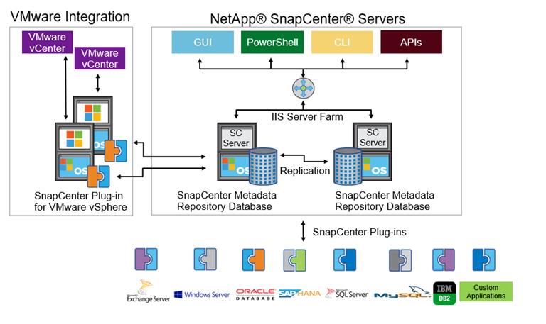
The SnapCenter Server has an HTML5-based GUI and Windows PowerShell cmdlets and APIs. The SnapCenter Server is capable of high availability out of the box. If one SnapCenter host becomes unavailable for any reason, then the second SnapCenter Server can take over seamlessly and no operations are affected.
The SnapCenter Server can push out plug-ins to remote hosts. These plug-ins are used to interact with applications, databases, or file systems. Usually, the plug-ins must be present on the remote host so that application-level or database-level commands can be issued from the same host where the application or database is running.
SnapCenter uses SM Service to manage plug-ins and interactions between the SnapCenter Server and the plug-in host. SM Service is a NetApp SnapManager® web service running on top of Windows Server internet information services (IIS) on SnapCenter Server. SM Service takes all client requests such as backup, restore, and clone.
The SnapCenter Server communicates those requests to SMCore, a service that runs within the SnapCenter Server and remote servers. SMCore plays a significant role in coordinating with the SnapCenter plug-ins package for Windows.
SnapCenter Virtualization (SCV) is a plug-in that manages virtual servers running on VMware and helps to discover the host file system, databases on virtual machine disks (VMDKs), and raw device mapping (RDM).
SnapCenter features
SnapCenter enables you to create application-consistent Snapshot copies and to complete data protection operations, including Snapshot copy-based backup, clone, restore, and backup-verification operations. SnapCenter provides a centralized management environment, and it uses role-based access control (RBAC) to delegate data protection and management functions to individual application users across the SnapCenter Server and Windows hosts.
SnapCenter includes the following key features:
· A unified and scalable platform across applications and database environments with virtual and nonvirtual storage powered by the SnapCenter Server
· Consistency of features and procedures across plug-ins and environments supported by the SnapCenter UI
· Role-based access control (RBAC) for security and centralized role delegation
· Application-consistent Snapshot copy management, restore, clone, and backup verification support from both primary and secondary destinations (NetApp SnapMirror and NetApp SnapVault® technology)
· Remote package installation from the SnapCenter GUI
· Nondisruptive, remote upgrades
· A dedicated SnapCenter repository for faster data retrieval
· Load balancing that is implemented by using Microsoft Windows network load balancing (NLB) and application request routing (ARR) with support for horizontal scaling
· Centralized scheduling and policy management to support backup and clone operations
· Centralized reporting, monitoring, and dashboard views
· SnapCenter 4.3 support for data protection for VMware virtual machines, SQL Server databases, Oracle databases, MySQL, SAP HANA, MongoDB, and Microsoft Exchange
SAP HANA Data Protection with SnapCenter
The FlexPod solution can be extended with additional software and hardware components to cover data protection, backup and recovery, and disaster recovery operations. The following chapter provides a high-level overview of how to enhance SAP HANA backup and disaster recovery using the NetApp SnapCenter plug-In for SAP HANA.
More details on the setup and configuration of SnapCenter for backup and recovery or disaster recovery operations can be found in the following technical reports:
SAP HANA Backup and Recovery with SnapCenter
SAP HANA Disaster Recovery with Asynchronous Storage Replication
SAP HANA Backup
Storage-based Snapshot backups are a fully supported and integrated backup method available for SAP HANA.
Storage-based Snapshot backups are implemented with the NetApp SnapCenter plug-in for SAP HANA, which creates consistent Snapshot backups by using the interfaces provided by the SAP HANA database. SnapCenter registers the Snapshot backups in the SAP HANA backup catalog so that they are visible within the SAP HANA studio or cockpit and can be selected for restore and recovery operations.
Snapshot copies created within primary storage can be replicated to the secondary backup storage by using NetApp SnapMirror technology controlled by SnapCenter. Different backup retention policies can be defined for backups held on the primary storage and to those backups held on the secondary storage. The SnapCenter Plug-In for SAP HANA manages the retention of Snapshot copy-based data backups and log backups, including housekeeping of the backup catalog. The SnapCenter plug-in for SAP HANA also allows the execution of a block integrity check of the SAP HANA database by executing a file-based backup.
Storage-based Snapshot backups provide significant advantages when compared to file-based backups. Advantages include the following:
· Rapid backup (less than a minute)
· Faster restore on the storage layer (less than a minute)
· No performance effect on the SAP HANA database host, network, or storage during backup
· Space-efficient and bandwidth-efficient replication to secondary storage based on block changes
SAP HANA Disaster Recovery with Asynchronous Storage Replication
SAP HANA disaster recovery can be performed either on the database layer by using SAP system replication or on the storage layer by using storage replication technologies. This section provides an overview of disaster recovery solutions based on asynchronous storage replication.
The same SnapCenter plug-in that is described in section SAP HANA Backup is also used for the asynchronous mirroring solution. A consistent Snapshot image of the database at the primary site is asynchronously replicated to the disaster recovery site with SnapMirror.
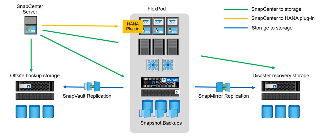
High-level architecture description
Figure 21 shows a high-level overview of the data protection architecture.
For an offsite backup and disaster recovery solution, the following additional hardware and software components are required:
· A Windows host to run SnapCenter server software
· Offsite backup storage to replicate backups from primary storage to a secondary storage system
· Disaster recovery storage to replicate backups from primary storage to a disaster recovery site
The SnapCenter server must be able to communicate with the SVMs that are used at the primary (within the FlexPod instance), the offsite backup location, and the disaster recovery storage.
The primary storage must have a network connection to the offsite storage and the disaster recovery storage. A storage cluster peering must be established between the primary storage, the offsite storage, and the disaster recovery storage.
The SnapCenter server must have a network connection to the SAP HANA database hosts to deploy the HANA plug-in and to communicate with the plug-in after deployment. As an alternative, the HANA plug-in can also be deployed at the FlexPod management server. See SAP HANA Backup and Recovery with SnapCenter for more details on the deployment options for the HANA plug-in.
Figure 21 Data protection with SnapCenter
SAP landscape management
SAP Landscape Management (LaMa) enables SAP system administrators to automate SAP system operations, including end-to-end SAP system copy and refresh operations. SAP LaMa is one of the few SAP software products with which infrastructure providers such as NetApp and Cisco can integrate their products. With such integration, customers can employ NetApp functions directly from the SAP LaMa GUI.
NetApp offers NetApp Storage Services Connector (SSC) that allows SAP LaMa to directly access technologies and features such as NetApp FlexClone® instant cloning and NetApp SnapMirror data replication. These technologies help minimize storage use and shorten the time required to create SAP system clones and copies.
With the help of the built-in functions and a rich set of extensibility features within SAP LaMa, FlexPod customers can directly integrate storage-based backups or instantaneously create space-efficient FlexClone system copies on the primary datacenter; they can even use storage at either the offsite backup or disaster recovery site.
Figure 22 shows how SAP LaMa and NetApp SSC can be integrated into the overall FlexPod architecture.
Figure 22 SAP landscape management
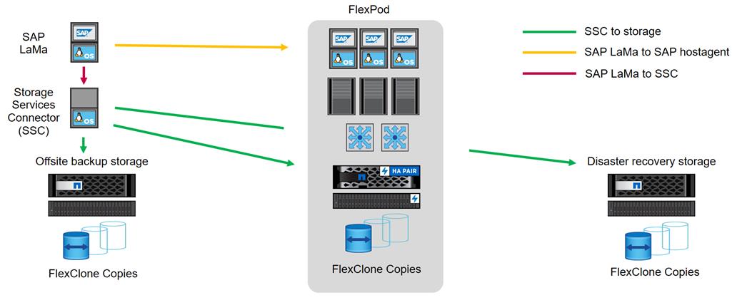
From an administrator's perspective, SAP LaMa is the central tool to operate and monitor SAP systems, compute instances, and required storage resources. Figure 18 also illustrates the required network communications between the different components.
SAP LaMa must be able to communicate with SAP Host Agent running on the physical or virtual host. Although SAP Host Agent is automatically installed during an SAP system installation, it can be manually configured to include hosts in SAP LaMa management that do not run SAP software, such as web servers.
To communicate with NetApp storage systems, SAP LaMa must be able to communicate with NetApp SSC. For more information about NetApp SSC, see the NetApp SSC for SAP LaMa site.
NetApp SSC version 4.0 is an executable that must be installed onto a Linux host that is accessible by SAP LaMa and is also able to connect to all NetApp storage systems integrated into SAP LaMa.
For a detailed description of SAP LaMa and the NetApp Storage Services Connector, see the technical report Integrating NetApp ONTAP systems with SAP Landscape Management.
![]() The SAP LaMa does not include regular backup and recovery or disaster recovery functionality. These functionalities are provided by SnapCenter.
The SAP LaMa does not include regular backup and recovery or disaster recovery functionality. These functionalities are provided by SnapCenter.
SAP application monitoring with AppDynamics
AppDynamics is an Application Performance Monitoring (APM) Platform that helps you to understand and optimize the performance of your business, from its software to infrastructure to business journeys.
The AppDynamics APM Platform enables you to monitor and manage your entire application-delivery ecosystem, from the mobile app or browser client request through your network, backend databases and application servers and more. AppDynamics APM gives you a single view across your application landscape, letting you quickly navigate from the global perspective of your distributed application right down to the call graphs or exception reports generated on individual hosts.
AppDynamics has an agent-based architecture. Once our agents are installed it gives you a dynamic flow map or topography of your application. It uses the concept of traffic lights to indicate the health of your application (green is good, yellow is slow and red indicates potential issues) with dynamics baselining. AppDynamics measures application performance based on business transactions which essentially are the key functionality of the application. When the application deviates from the baseline AppDynamics captures and provides deeper diagnostic information to help be more proactive in troubleshooting and reduce the MTTR (Mean Time To Repair).
For more information, go to: https://docs.appdynamics.com/display/SAP/SAP+Monitoring+Using+AppDynamics
The SAP HANA TDI option enables multiple SAP HANA production systems to run on the same infrastructure. In this configuration, the existing blade servers used by different SAP HANA systems share the same network infrastructure and storage systems. In addition, the SAP application server can share the same infrastructure as the SAP HANA database.
![]() SAP HANA in FlexPod environment qualify as SAP HANA TDI implementations.
SAP HANA in FlexPod environment qualify as SAP HANA TDI implementations.
FlexPod datacenter design
This section details the FlexPod Datacenter design with ACI and IP-based storage. The ACI fabric is providing IP-based iSCSI access to NetApp storage. The NetApp array is providing both NFS volumes and iSCSI LUNs for booting of Cisco UCS servers.
Figure 23 illustrates the end-to-end topology and the interconnections between the different components in the solution.
Physical Topology
Figure 23 FlexPod datacenter with Cisco ACI and NetApp AFF storage
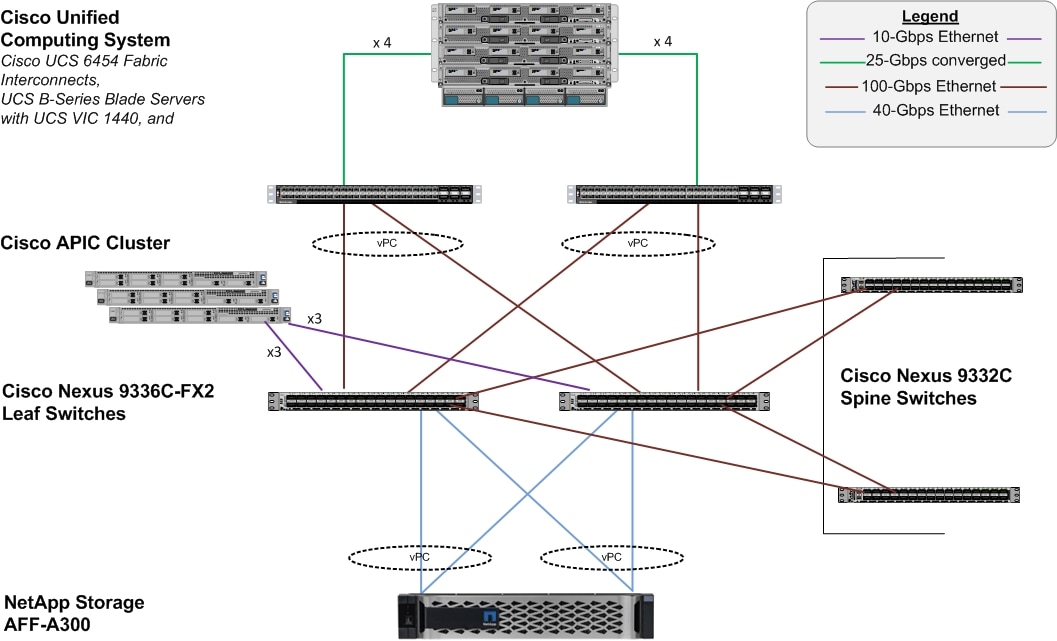
The reference architecture configuration includes:
· Cisco Nexus 9000 series Spine and Leaf Switches along with Cisco APIC cluster
· Two Cisco UCS 6400 series fabric interconnects
· One NetApp AFF A300 (HA controller pair) running ONTAP 9.6.
Connectivity design – compute layer
The Cisco UCS platform provides the compute resources in the FlexPod Datacenter with Cisco ACI solution. The design supports both Cisco UCS B-series blade servers and Cisco UCS C-series rack-mount servers, connected and managed through a pair of Cisco UCS Fabric Interconnects running Cisco UCS manager.
Each Cisco UCS server is equipped with a Virtual Interface Cards (VIC) that aggregate all LAN and SAN traffic to and from the server across a single interface.
The blade servers are housed in a Cisco UCS 5108 Blade Server Chassis that can support up to 8 Cisco UCS B200 M5s or 4 Cisco UCS B480 M5 blades. A blade server chassis can have up to two fabric extenders (FEX) or I/O Modules (IOM) that connect the chassis to the Fabric Interconnects.
In FlexPod designs, the supported Cisco UCS C-Series servers can be either directly connected to the FIs using 25GbE links or through supported top-of-rack Cisco Nexus Fabric Extenders that connects to the FIs. FlexPod designs do require that these servers be managed by Cisco UCS Manager in order to ensure consistent policy-based provisioning, stateless computing and uniform management of the server resources, independent of the form-factor.
Cisco UCS fabric interconnect connectivity to datacenter network
In this design, each Fabric Interconnect connects into a pair of upstream Nexus 9000 ACI leaf switches. The links on each FI are bundled into a port-channel while links on Nexus leaf switches that connect to this FI are bundled into a vPC. This design provides link and node-level redundancy, higher aggregate bandwidth and the flexibility to increase the bandwidth as the uplink bandwidth needs grow.
Validation - compute layer connectivity
To validate the compute layer design, a Cisco UCS 5108 server chassis with Cisco UCS B480 M5 blade servers are connected through a pair of Cisco UCS 6454 Fabric Interconnects as shown in Figure 24.
Figure 24 Validated - compute layer connectivity
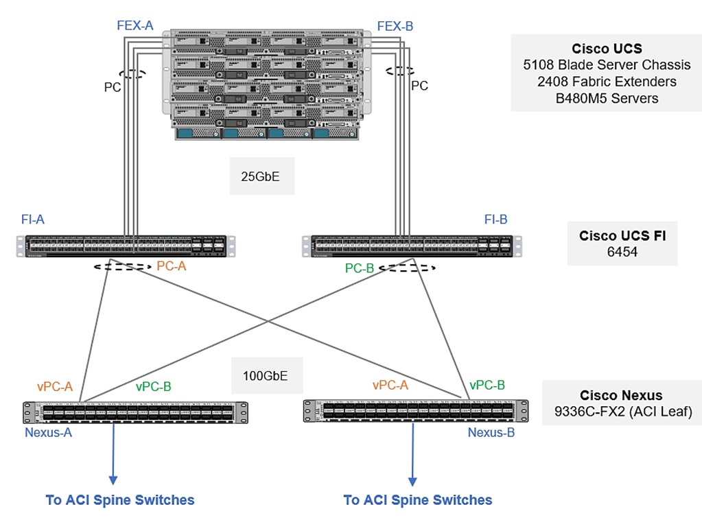
The blade server chassis is deployed using 2 x Cisco UCS 2408 FEX (IOMs), with each FEX connecting to one fabric interconnect, forming two distinct paths (Fabric-A, Fabric-B) through the unified fabric as follows:
· Fabric-A: 4 x 25GbE links from FEX-A to FI-A, links bundled into a port-channel
· Fabric-B: 4 x 25GbE links from FEX-B to FI-B, links bundled into a port-channel
This provides the blade server chassis with an aggregate uplink bandwidth of 200Gbps. Additional ports on each FEX can be used to further increase the bandwidth. For the Cisco UCS 2408 FEX model, all 8 ports can be used for a total of 400Gbps of uplink bandwidth to a single blade server chassis.
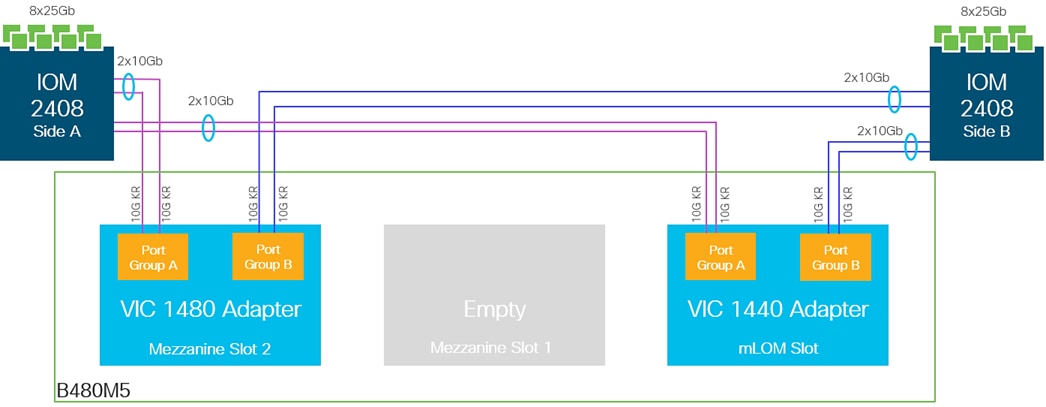
The blade servers in the blade server chassis are each deployed with a mLOM slot VIC 1440 and mezzanine VIC 1480 adapters, as illustrated in Figure 25. The VIC 1440 adapter provides 40Gbps of uplink connectivity, 20Gbps through each Fabric (Fabric-A, Fabric-B) path. The uplink bandwidth is increased to 40Gbps per Fabric path with the additional mezzanine slot VIC 1480 adapter. That gives 80Gbps to a Cisco UCS B480M5. It is highly recommended to use VIC 1440 + VIC 1480 for optimum bandwidth availability.
![]() The port expander slot with VIC 1440 is unsupported with IOM 2408.
The port expander slot with VIC 1440 is unsupported with IOM 2408.
Figure 25 Cisco UCS B480 M5 blade server VIC 1440/1480 uplink connectivity
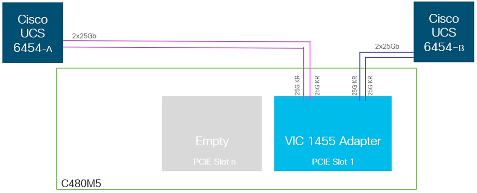
The Cisco UCS C480 M5 rack-mount servers are deployed with quad-port VIC 1455 adapter and directly connected to Fabric Interconnects, as shown in Figure 26, with two VIC (25GbE) port/s going to each FI, providing the rack servers with an aggregate uplink bandwidth of 100Gbps with high availability.
Figure 26 Cisco UCS C480 M5 rack-mount server - VIC 1455 uplink connectivity
To connect to the upstream data center network, each FI is connected to a pair of Nexus 9300 series leaf switches in the validation setup as follows:
· 6 x 40GbE links from FI-A to Leaf switches (Leaf-A, Leaf-B), three to each Leaf switch
· 6 x 40GbE links from FI-B to Leaf switches (Leaf-A, Leaf-B), three to each Leaf switch
The FI uplink ports are configured in two port channels one with 4 ports and other with 2 ports, with corresponding vPC configurations on the Leaf switches. This provides the UCS domain with redundant paths and 240 Gbps of aggregate uplink bandwidth to/from the ACI fabric. VLAN group configuration segregates the traffic so that high bandwidth port-channel caters to the HANA persistence as well as inter-node traffic [in case of multi-host scenarios] and other port channel tending to iSCSI boot, management and backup traffic. The uplink bandwidth can be further increased as needed by adding additional connections to the port-channel.
In the validation setup, 40G complaint cables were used. Leveraging 100GE links between FIs and Leaf switches is also possible with corresponding compatible cables.
Configuration with Cisco UCS 6300 Series Fabric Interconnects
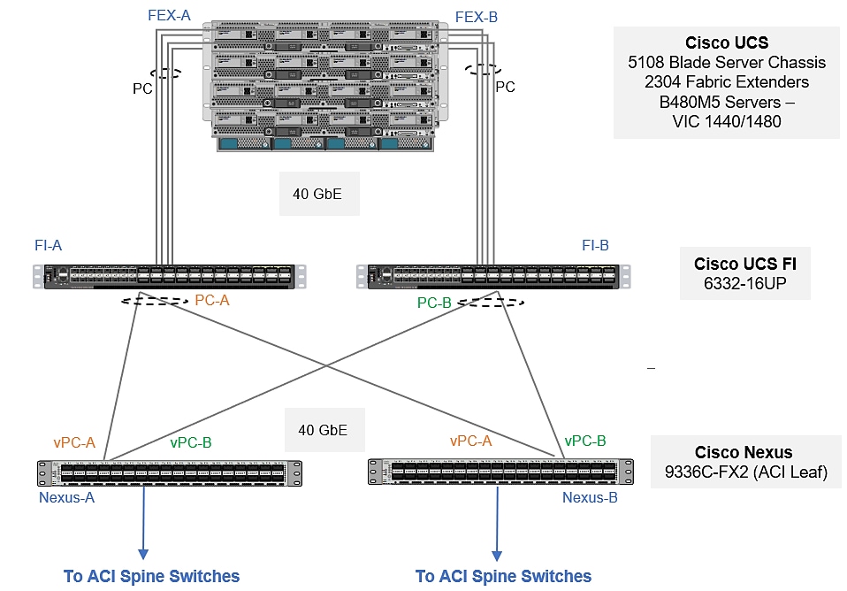
With Cisco UCS 6300 series fabric interconnects managing the Cisco UCS B480 M5 servers populated with VICs 1440, port expander and/or VIC 1480 via Cisco UCS 2304 FEXs, it will be an end-to-end 40 GbE, as illustrated in Figure 27.
Figure 27 Design option with 3rd Gen FIs
Design options
The Cisco UCS B-series servers used in the validated design setup are configured in the design with:
· iSCSI boot – Persistent operating system installation, independent of the physical blade for true stateless computing.
· VIC 1440 + VIC 1480
· Intel® Optane™ Data Center Persistent Memory Module (DCPMM)
Memory for databases is currently small, expensive, and volatile. Intel Optane DC persistent memory is denser, more affordable, and persistent, and it performs at speeds close to that of memory. These features of Intel Optane DC persistent memory can help lower TCO through reduced downtime and simplified data-tiering operations. These same features can also make SAP HANA in-memory databases economically viable for a wider range of use cases. Intel Optane DC persistent memory provides near-DRAM in-memory computing speed in a form factor similar to that of dual inline memory modules (DIMMs) at a lower price per gigabyte than DRAM. . With its persistence, performance, and lower cost per gigabyte than conventional memory, Intel Optane DC persistent memory can help reduce total cost of ownership (TCO), reshape the way that businesses tier their data for database systems, and open new use cases for the speed and power of the SAP HANA platform.
Table 3 and Table 4 lists the server specifications with possible memory configurations for the SAP HANA use case.
Table 3 Cisco UCS B480 M5 blade server and Cisco UCS C480 M5 rack server configuration
| CPU specifications |
Intel Xeon Platinum 8276L/8280L processor: Quantity 4 |
| Possible memory configurations |
32-GB DDR4: Quantity 24 (768 GB) 64-GB DDR4: Quantity 24 (1.5 TB) 128-GB DDR4: Quantity 24 (3 TB) |
| Possible DCPMM memory configurations |
128-GB DCPMM: Quantity 24 (3 TB) 256-GB DCPMM: Quantity 24 (6 TB) 512-GB DCPMM: Quantity 24 (12 TB) |
Table 4 Cisco UCS C240 and Cisco UCS C220 M5 rack server and Cisco UCS B200 M5 blade server configuration
| CPU specifications |
Intel Xeon Platinum 8276L/8280L processor: Quantity 2 |
| Possible memory configurations |
16-GB DDR4: Quantity 12 (192 GB) 32-GB DDR4: Quantity 12 (384 GB) 64-GB DDR4: Quantity 12 (768 TB) 128-GB DDR4: Quantity 12 (1.5 TB) |
| Possible DCPMM memory configurations |
128-GB DCPMM: Quantity 12(1.5 TB) 256-GB DCPMM: Quantity 12 (3 TB) 512-GB DCPMM: Quantity 12 (6 TB) |
Intel Optane DCPMMs must be installed with DRAM DIMMs in the same system. The persistent memory modules will not function without any DRAM DIMMs installed. In two-, four-, and eight-socket configurations, each socket contains two IMCs. Each memory controller is connected to three double data rate (DDR) memory channels that are then connected to two physical DIMM persistent memory slots.
![]() SAP HANA 2.0 SPS 03 currently supports various capacity ratios between Intel Optane DCPMMs and DIMMs.
SAP HANA 2.0 SPS 03 currently supports various capacity ratios between Intel Optane DCPMMs and DIMMs.
For information regarding the Cisco UCS compute with Intel Optane DC Persistent Memory Module (DCPMM) and possible capacity ratios between DCPMMs and DIMMs, go to: https://www.cisco.com/c/dam/en/us/products/servers-unified-computing/ucs-b-series-blade-servers/whitepaper-c11-742627.pdf
Connectivity Design – storage layer
The FlexPod Datacenter with Cisco ACI solution is an end-to-end IP-based storage solution with iSCSI-based SAN access. This design uses NetApp AFF A300 to provide the storage resources. NetApp Storage connects into the ACI fabric using dual 40GbE uplinks, configured for port-channeling to provide higher aggregate bandwidth and availability. Nexus Leaf switches that connect to the NetApp storage is configured for vPC to provide node-availability, in addition to link-availability and higher aggregate bandwidth.
Validation – storage layer connectivity
To validate the storage layer design for IP-based storage access to application and boot volumes using iSCSI and NFS, the NetApp A300 array deployed as a high availability controller pair and connected to a pair of Nexus leaf switches as shown in Figure 28. The NetApp A300 is running clustered Data ONTAP 9.6 in a switchless cluster configuration.
Figure 28 Validated - storage layer connectivity
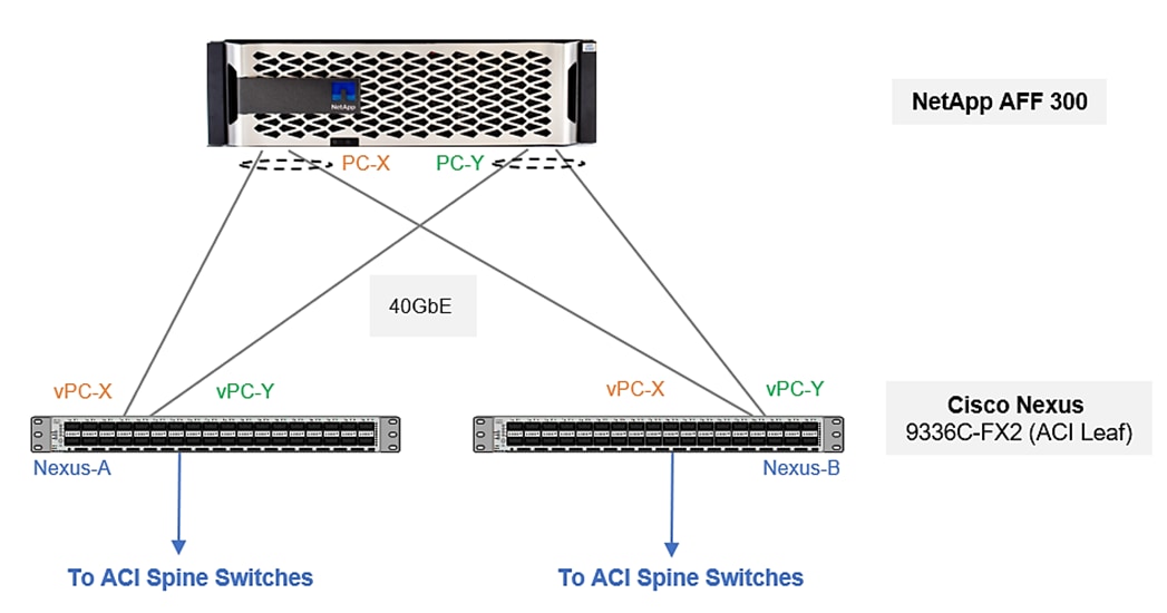
NetApp AFF A300 supports 40GbE connections. To connect to the upstream data center network, the AFF A300 is connected to a pair of Nexus 9300 series leaf switches as follows:
· 2 x 40GbE links from each array controller’s IOM ports to leaf switches, one link to each leaf (Nexus-A, Nexus-B)
· Port-channel configuration with 2 x 40GbE ports on each array controller
· vPC configuration on Nexus leaf switches, one vPC to each NetApp controller. Each VPC has 2 links, one from each Nexus switch to a NetApp controller.
The connectivity described above, provides each NetApp AFF A300 with redundant uplinks through separate leaf switches and 80Gbps (160Gbps for the HA controller pair) of bandwidth to the ACI fabric.
NetApp AFF storage system family
Since all NetApp AFF storage systems use ONTAP as the storage operating system, the functionality of ONTAP is available starting with entry class systems, over mid-range systems, and all the way up to high end systems. It is important to note the supported ports: 25GbE/40GbE/100GbE available on the NetApp Array that is being used and leverage the compatible links while connecting to Leaf Switches. For example, with NetApp AFF A400 array, we could leverage 25/100 GbE connectivity depending on speeds supported by the leaf switch used. This allows you to choose the right storage system for your needs.
Storage design considerations
For storage design considerations, refer to the following NetApp storage design best practices and recommendations, here: TR-4435: SAP HANA on NetApp All Flash FAS Systems with NFS Configuration Guide
Connectivity design – network layer
The ACI fabric is based on a spine-leaf architecture, built using Nexus 9000 series switches where each leaf switch connects to every spine switch, using high speed links and with no direct connectivity between leaf nodes or between spine nodes. Multiple models of Nexus 9000 series switches that support ACI spine and leaf functionality are available and supported in FlexPod.
In ACI, spine switches form the core of the ACI fabric and provide high-speed (40/100GbE) connectivity between leaf switches. A spine can be a:
· Modular Cisco Nexus 9500 series switch equipped with 40/100GbE capable line cards such as N9K-X9736PQ, N9K-X9736C-FX, N9K-X9732C-EX, and so on.
· Fixed form-factor Cisco Nexus 9300 series switch with 40/100GbE ports (such as N9K-C9332C, N9K-C9364C)
The edge of the ACI fabric are the leaf switches. Leaf switches are top-of-rack (ToR), fixed form factor Nexus switches such as N9K-C9336-FX2, N9K-C93180LC-EX, N9K-C93180YC-EX/FX switches. These switches will typically have 40/100GbE uplink ports for high-speed connectivity to spine switches and access ports that support a range of speeds (1/10/25/40GbE) for connecting to servers, storage and other network devices.
Leaf switches provide access layer functions such as traffic classification, policy enforcement, traffic forwarding and serve as an attachment point to the ACI fabric. Nexus leaf switches also provide several advanced capabilities such as support for analytics in hardware, advanced traffic management, encryption, traffic redirection for L4-L7 services, and so on.
In this design, the following components are physically connected to the leaf switches:
· Cisco APICs that manage the ACI Fabric (3-node cluster)
· Cisco UCS Compute Domain (Pair of Cisco UCS Fabric Interconnects)
· NetApp Storage (NetApp AFF A300)
· Optionally, Management Network Infrastructure in customer’s existing management network (Outside Network)
Cisco ACI supports virtual Port-Channel (vPC) technology on leaf switches to increase throughput and resilience. Virtual Port channels play an important role on leaf switches by allowing the connecting devices to use 802.3ad LACP-based port-channeling to bundle links going to two separate leaf switches. Unlike traditional NX-OS vPC feature, the ACI vPC does not require a vPC peer-link to be connected nor configured between the peer leaf switches. Instead, the peer communication occurs through the spine switches, using the uplinks to the spines. The vPCs can therefore be created between any two leaf switches, in the ACI fabric through configuration, without having to do additional cabling between switches.
![]() When creating a vPC between two leaf switches, the switches must be of the same hardware generation. Generation 2 models have -EX or -FX or -FX2 in the name while Generation 1 does not.
When creating a vPC between two leaf switches, the switches must be of the same hardware generation. Generation 2 models have -EX or -FX or -FX2 in the name while Generation 1 does not.
In this FlexPod design, vPCs are used for connecting the following access layer devices to the ACI fabric:
· Two vPCs, one to each Fabric Interconnect in the Cisco UCS Compute Domain
· Two vPCs, one to each NetApp storage array in the HA-pair
· Single back-to-back vPC to Nexus switches of customer’s existing management network
The other access layer connections are individual connections; they are not part of a vPC bundle.
ACI fabric
The Cisco ACI fabric is a Layer 3, routed fabric with a VXLAN overlay network for enabling L2, L3 and multicast forwarding across the fabric. VXLAN overlays provide a high degree of scalability in the number of Layer 2 segments it can support as well as the ability to extend these Layer 2 segments across a Layer 3 network. The ACI fabric provides connectivity to both physical and virtual workloads, and the compute, storage and network resources required to host these workloads in the data center.
The ACI architecture is designed for multi-tenancy. Multi-tenancy allows the administrator to partition the fabric along organizational or functional lines into multiple tenants. The ACI fabric has three system-defined tenants (mgmt, infra, common) that gets created when a fabric first comes up. The administrator defines the user tenants as needed to meet the needs of the organization; shared-services tenant for hosting infrastructure services such as Microsoft Active Directory (AD), Dynamic Name Services (DNS), and so on.
ACI fabric connectivity design
This ACI fabric design is as shown in Figure 29. It consists of a pair of Nexus 9332C spine switches, a 3-node APIC cluster and a pair of Nexus 9336C-FX2 leaf switches that the Cisco APICs connect into using 10GbE – APICs only support 10GbE uplinks currently. The core provides 40GbE connectivity between leaf and spine switches. The fabric design can support other models of Nexus 9000 series switches, provided it has the required interface types, speeds and other capabilities.
Figure 29 Cisco ACI fabric architecture
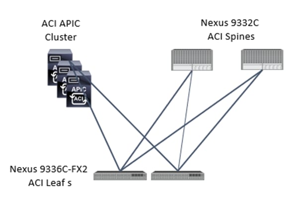
In this FlexPod design, a pair of Nexus 9336C-FX2 leaf switches provide connectivity to downstream compute, storage and other network sub-systems, as shown in Figure 30. The leaf switches use 40GbE links to connect to spine switches (Nexus 9332C) and for downstream connectivity to Cisco UCS servers; they leverage 40GbE for connectivity to NetApp storage. In the validation setup, leaf pair connect to management landscape Nexus switches via a back-to-back vPC leveraging 40GE links.
Figure 30 FlexPod Datacenter – ACI fabric sub-system connectivity (high-level)
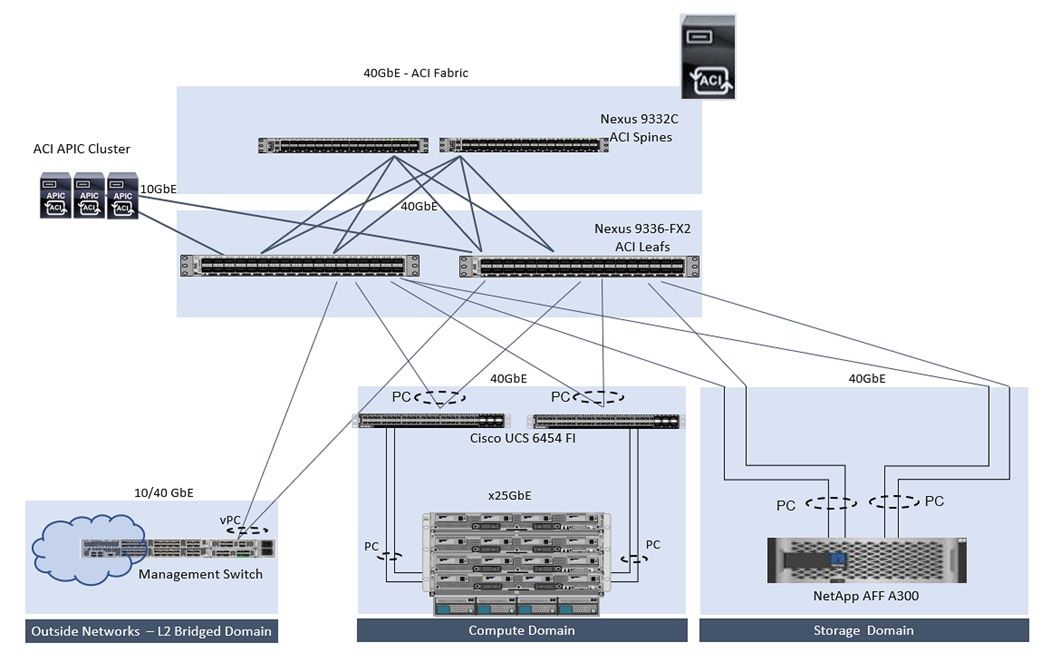
The access layer connections on the ACI leaf switches to the different subsystems are summarized below:
· A Cisco UCS Compute domain consisting of a pair of Cisco UCS 6454 fabric interconnects, connect into a pair of Nexus 9336C-FX2 leaf switches using port-channels, one from each FI. Each FI connects to the leaf switch-pair using member links from one port-channel. On the leaf switch-pair, the links from each FI are bundled into a vPC. This design uses 6x40GbE links from each FI to leaf-switch pair to provide the UCS compute domain with an uplink bandwidth of 240Gbps. Additional links can be added to the bundle as needed, to increase the uplink bandwidth.
· A NetApp Storage cluster consisting of NetApp AFF A300 array, connects into a pair of Nexus 933C-FX2 leaf switches using port-channels, one from each array controller’s IOM port. Each controller connects to the leaf switch-pair using member links from one port-channel. On the leaf switch-pair, the links from each controller are bundled into a vPC. This design uses 2x40GbE links from each controller to leaf-switch pair to provide the NetApp storage domain with an uplink bandwidth of 160Gbps. Additional links can be added with more IOM cards installed, as needed, to increase the uplink bandwidth. This design supports both NFS and iSCSI for storage access.
· To connect to an existing management network outside the ACI fabric, a single back-to-back vPC is used to connect to the customer’s management network infrastructure, in this case, a Nexus 9000 series switch pair in vPC. A 40GbE vPC from a pair of leaf switches connects to a port-channel on the Nexus 9k switch pair. From the ACI fabric’s perspective, this is a L2 bridged connection.
ACI fabric design – access policies
Fabric Access Policies is an important aspect of the Cisco ACI architecture. Fabric Access Policies are defined by the Fabric Administrator and includes all the configuration and policies required to connect access layer devices to the ACI fabric. This must be in place before Tenant Administrators can deploy Application EPGs. These policies are designed to be reused as new leaf switches and access layer devices are connected to the fabric.
Fabric Access refers to access layers connections at the fabric edge to external devices such as:
· Cisco UCS servers via Cisco UCS FIs, NetApp Storage Controllers and optional management switches.
Access Policies include any configuration that can applied to the above connections such as:
· Enabling PC, vPC on the links to the external devices
· Configuring Interface Policies (e.g. VLAN scope, Link Speed, LACP, LLDP, CDP)
· Interface Profiles
Access Polices also include configuration and policies for leaf switches such as:
· VLAN pools
· Switch Policy Group and Profiles
· Global policies such as AEP
The Fabric Access Policies used in the FlexPod design to connect to an outside Management network, UCS domains and the storage domain are shown in Figure 31. Once the policies and profiles are in place, they can be reused to add new leaf switches and connect new endpoints to the ACI fabric. Note that the Create an Interface, PC, and vPC wizard simplifies this task.
Figure 31 Fabric Access Policies to connect to UCS domain, storage subsystem and management
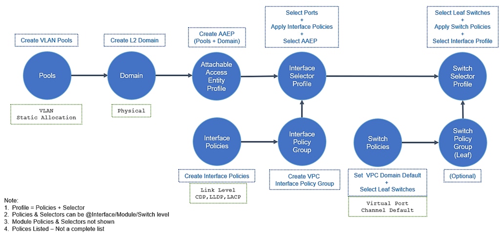
Fabric access design – access policies (VLAN pools) and VLAN design
Cisco ACI uses a VXLAN overlay network for communication across the fabric but use VLANs (or VXLAN) to communicate with devices outside the fabric. Unlike other data center architectures, VLANs in ACI are used to classify incoming traffic based on their VLAN tag but are not used to make forwarding decisions within the fabric. The traffic received on a VLAN are classified and mapped to an Endpoint group (EPG). EPG is a fundamental construct in ACI and forms the basis for policies and forwarding through the fabric. The EPG policies will determine the forwarding, and VXLAN tunnels will transport the traffic across the ACI fabric. For more details, see Cisco ACI Fundamentals listed in the Solution References section.
The Fabric Administrator defines and manages access configuration on a switch through fabric access policies. These policies include domains and VLAN pools, where the pools specify the allowed range of VLANs and the domains specify the scope of the associated vlan pool. In ACI, a domain can be physical (such as rackmount server, storage array), virtual (such as virtual machine manager or VMM) or external (such as L2 or L3 networks outside the ACI fabric).
In this design, primarily focused on the bare-metal implementations, Static VLAN Allocation is used on connections to physical devices in ACI. This includes connections to the FIs in the Cisco UCS domain, NetApp Storage Cluster and other networks [separate management network] outside the ACI fabric.
The tables below show the EPG VLANs used in the FlexPod design. These VLANs are enabled on the port-channels connecting leaf switches to access layer devices and provide compute, storage and management domains access to the ACI fabric.
Table 5 Access layer connectivity on leaf switches – EPG VLANs to management switch
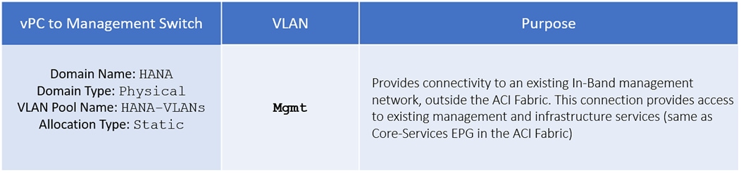
Table 6 Access layer connectivity on leaf switches – EPG VLANs to NetApp AFF storage cluster
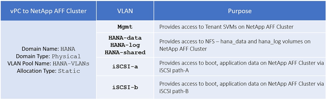
Table 7 Access layer connectivity on leaf switches – EPG VLANs to Cisco UCS compute domain
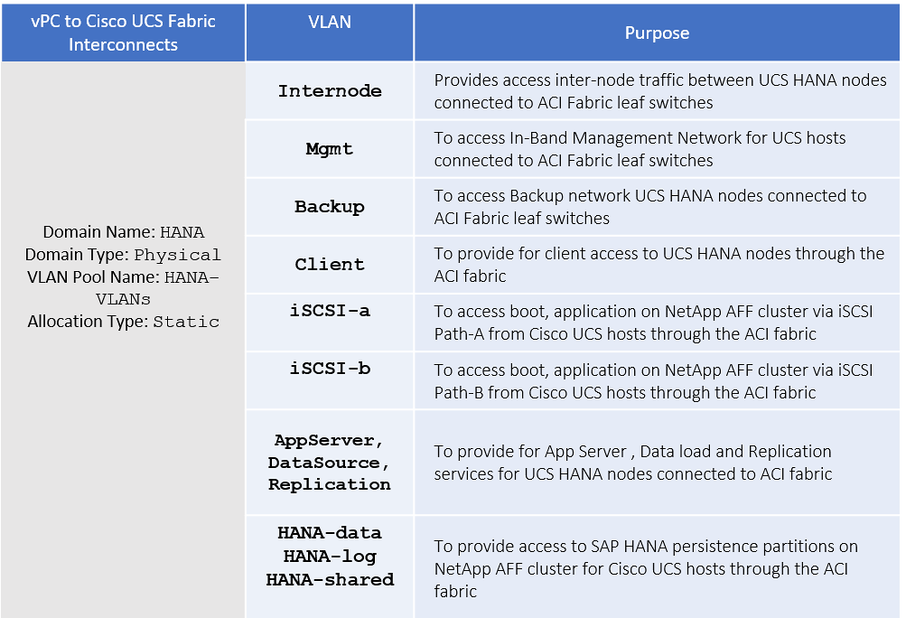
VLAN scalability (4096 VLANs) can be a limitation in traditional data center networks but since VLAN are only used at the edge to communicate with devices outside the fabric.
The VLAN guideline used in the FlexPod design is when deploying an EPG with static binding to a physical interface, the VLAN ID specified must be from the allowed range of VLANs for that interface. The domain association for the EPG maps to a VLAN pool and this domain must also be associated with physical interface. The domain and the associated VLAN pool is mapped to the physical interface through the Access Entity Profile (AEP). AEP defines the scope of the VLAN (VLAN pool) on the physical infrastructure (port, PC or vPC). This ensures that the EPG VLAN deployed on the physical infrastructure is within the range of VLANs allowed on that infrastructure.
Fabric access design – access policies (ACI domains)
Domains in ACI are used to define how different entities (for example, servers, network devices, storage) connect into the fabric and specify the scope of a defined VLAN pool. While you can define different domains and their corresponding VLAN ranges for the various devices that connect to the leaf switch, the current design treats everything as one HANA domain and also defines a statically allocated VLAN range that will be used in the HANA landscape.
Table 8 Access Layer Connectivity on Leaf Switches – ACI Domain
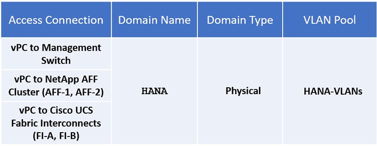
Fabric access design – access policies (Attachable Entity Profile)
Attachable Entity Profile (AEP) is an ACI construct for grouping external devices with common interface policies. AEP is also known as a Attachable Access Entity Profile (AAEP).
AEP also link ACI domains (and VLAN pools) to the physical infrastructure through Interface and Switch Selector Profiles, thereby defining the scope of the VLAN pool on the physical infrastructure.
ACI provides multiple attachment points for connecting access layer devices to the ACI fabric. Interface Selector Profiles represents the configuration of those attachment points. Interface Selector Profiles are the consolidation of a group of interface policies (such as LACP, LLDP, CDP) and the interfaces they apply to. The Interface Profiles and AEPs can be reused across multiple switches if the policies and ports are the same.
Figure 32 AEP mapping to interface and switch policies for UCS domain
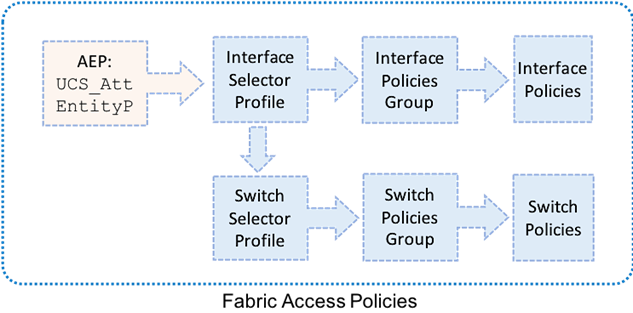
While multiple AEPs are required to support overlapping VLAN pools, in this design, a single HANA AAEP is created that addresses the use cases of SAP HANA implementation. There is a one-to-one mapping between AEPs and Domain and VLAN Pool in this design, see the table below.
Table 9 AEP to Domain Mapping
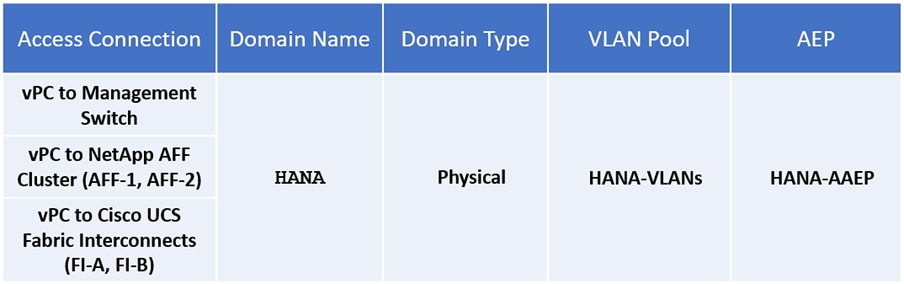
ACI fabric design – tenant, EPGS, application profiles, bridge domains and contracts
Tenant Configuration
While the Fabric and Access Policies dealt with physical aspects of the fabric setup, Tenant provides for a logical container or a folder for application policies This container can represent an actual tenant, an organization, an application or a group based on some other criteria. A tenant represents a unit of isolation from a policy perspective. All application configurations in Cisco ACI are part of a tenant.
ACI provides two categories of tenants: User Tenants and System Tenants. System Tenants include Common, Infra and Mgmt Tenants.
The FlexPod design uses the Common tenant to host core services such as AD, DNS, and so on. ACI provided Common Tenant is designed for shared services that all tenants need.
This design also includes a user-tenant called T01-HANA to provide, standing for 1st HANA system tenant in a multi-tenant architecture. It accounts for:
· Compute to storage connectivity for access to iSCSI LUNs, HANA persistence partitions.
· Access to HANA nodes administration network from the external Management PoD
· All required access for SAP HANA system
![]() For a multi-tenancy environment, each tenant can be configured with identical categories, port channels, and so on. However, VLAN use within a tenant would need to be unique between tenants.
For a multi-tenancy environment, each tenant can be configured with identical categories, port channels, and so on. However, VLAN use within a tenant would need to be unique between tenants.
VRF
A virtual routing and forwarding (VRF) instance in ACI is a tenant network. VRF is a unique Layer 3 forwarding domain. A tenant can have multiple VRFs and a VRF can have multiple bridge domains. In the FlexPod design, a single VRF is created in each tenant created.
Application End Point Groups [EPGs]
An End Point Group (EPG) in ACI is a logical entity that contains a group of endpoints. Endpoints can be physical or virtual and require a common set of policies or services or provide a common set of services or other functions. By grouping them, the endpoints can be managed as a group rather than individually.
EPGs are defined based on the common set of services that end devices grouped in separate networks, provide or consume. For example, the iSCSI-initiators on Cisco UCS servers and iSCSI-targets on NetApp are part of same EPG. Similarly, the Admin network defined for HANA nodes and external management network that use the same VLAN/subnet are part of same EPG. This scheme is extended to SAP HANA filesystems configured on NetApp array and their corresponding client networks defined in the HANA nodes. In the FlexPod design for SAP HANA, we define the EPGs based on the following networks subsequently the subnets/VLAN they share:
· HANA nodes configured with certain networks based on whether it is Multi-host or Single-host implementation, whether it needs to connect to an existing backup network, or needs replication service to be configured and so on.
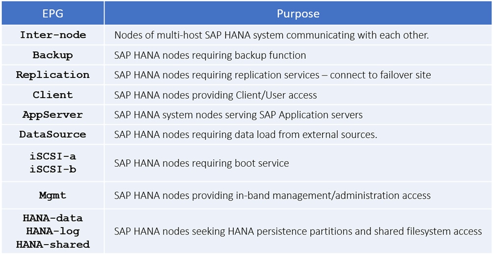
· NetApp storage controllers providing certain filesystem access via designated networks.
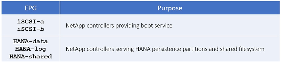
· Management PoD providing management services for HANA nodes.

EPGs can be static or dynamic depending whether the endpoints are added to the EPG using a static binding or dynamically. We use static binding in this design.
Application Profiles
An application profile models application requirements and contains one or more EPGs as necessary to enable multi-tier applications and services. This design demonstrates with one application profile HANA-Multi-host ad-dressing the broader Multi-host system use-case.
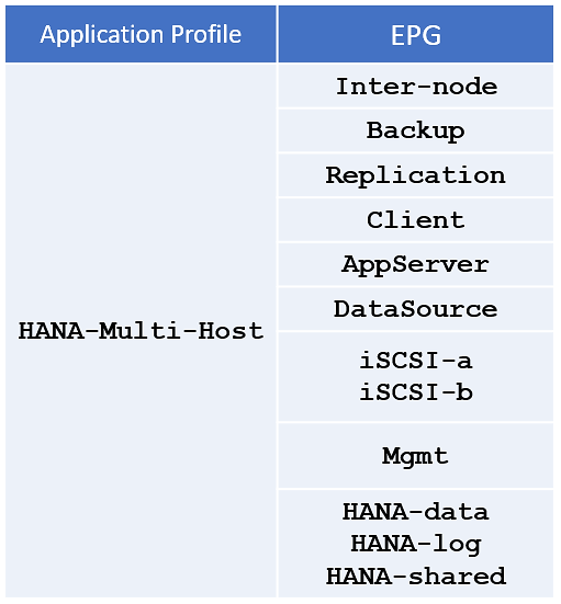
Bridge Domains
A bridge domain represents a Layer 2 forwarding construct within the fabric. The bridge domain can be further segmented into EPGs. Like EPGs, bridge domains can also span multiple switches. A bridge domain can contain multiple subnets, but a subnet is contained within a single bridge domain. One or more bridge domains together form a tenant network. A bridge domain represents the broadcast domain and has global scope. EPGs must be associated with bridge domain.
Bridge Domains are an important consideration in the FlexPod design. When a bridge domain contains endpoints belonging to different VLANs (outside the ACI fabric), a unique MAC address is required for every unique endpoint. NetApp storage controllers, however, use the same MAC address for an interface group and all the VLAN interface ports defined for that interface group on that storage node. As a result, all the LIFs on a NetApp interface group end up sharing a single MAC address even though these LIFs belong to different VLANs.
To overcome potential issues caused by overlapping MAC addresses, multiple bridge domains are specifically needed for correct storage connectivity. Make EPGs that need to talk to each other, part of the same bridge domain while you configure it per EPG basis for those that need to be isolated.
Table 10 lists the EPG to Bridge Domain mapping using in the design.
Table 10 FlexPod design – EPGs and bridge domains
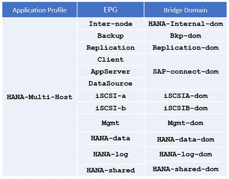
Contracts
Contracts define inbound and outbound traffic filter, QoS rules and Layer 4 to Layer 7 redirect policies. Contracts define the way an EPG can communicate with another EPG(s) depending on the application requirements. Contracts are defined using provider-consumer relationships; one EPG provides a contract and another EPG(s) consumes that contract. Contracts utilize filters to limit the traffic between the applications to certain ports and protocols.
A service contract exists between two or more participating peer entities, such as two applications running and communicating with each other behind different endpoint groups, or between providers and consumers, such as a DNS contract between a provider entity and a consumer entity.
You need to create individual contracts between the EPGs that need to talk to each other leveraging the ‘default’ filter that allows all traffic between them.
![]() The common/default filter allows all communication between the corresponding endpoints. A filter can be created to limit the communication port and protocol between two endpoints; this configuration is beyond the scope of this document.
The common/default filter allows all communication between the corresponding endpoints. A filter can be created to limit the communication port and protocol between two endpoints; this configuration is beyond the scope of this document.
SAP HANA system implementation options
Since multiple implementation options are available specific to this shared TDI usage, you need to define your requirements before you can select the solution components. This section defines the basic requirements for each option.
Single SAP HANA system on a single server: Single-host (bare metal or virtualized)
A single-host TDI solution is the simplest of the installation types. In general, this solution provides the best SAP HANA performance. All data and processes are located on the same server and can be accessed locally, and no network communication with other SAP HANA nodes is required. SAP HANA single-host TDI solutions are based on a standalone rack-mount server or blade server and use the intended external storage.
The network requirements for this option depend on the client and application access and storage connections. If you don’t need system replication or a backup network, a 1 Gigabit Ethernet (access) network and bandwidth factored for the data, log and shared filesystem access storage networks are required to run SAP HANA in a single-host configuration.
![]() The storage IO as well as latency Key Performance Indicators (KPI) requirements by SAP need to be fulfilled.
The storage IO as well as latency Key Performance Indicators (KPI) requirements by SAP need to be fulfilled.
For a virtualized SAP HANA installation, remember that hardware components, such as network interfaces and host bus adapters (HBAs), are shared. If possible, use dedicated network adapters and HBAs for each virtualized SAP HANA system. The storage requirements are similar to a bare metal use case with respect to storage IO and latency KPIs.
Single SAP HANA system on multiple servers: Multi-host
You should use a multi-host TDI solution if the SAP HANA system does not fit into the main memory of a single server based on the rules defined by SAP. In this method, multiple independent servers are combined to form one system and the load is distributed among multiple servers. In a distributed system, each index server is usually assigned to its own host to achieve maximum performance. It is possible to assign different tables to different hosts (partitioning the database), or a single table can be split across hosts (partitioning of tables). SAP HANA multi-host supports failover scenarios and high availability. Individual hosts in a distributed system have different roles master, worker, slave, standby depending on the task.
The network requirements for this option are higher than for single-host systems. In addition to the client and application access and storage access networks, you also must have a node-to-node network. If you don’t need system replication or a backup network, a 10 Gigabit Ethernet (access) network and a mandatory minimum of 10 Gigabit Ethernet (node-to-node) and bandwidth factored for the data, log and shared filesystem access storage networks are required to run SAP HANA in a multi-host configuration.
![]() Make sure the IO as well as latency KPI requirements by SAP are fulfilled for the storage configuration.
Make sure the IO as well as latency KPI requirements by SAP are fulfilled for the storage configuration.
For a virtualized SAP HANA installation, remember that hardware components, such as network interfaces and host bus adapters (HBAs), are shared. If possible, use dedicated network adapters and HBAs for each virtualized SAP HANA system. The network and storage requirements are similar to a bare metal use case with respect to storage IO/latency and inter-node network bandwidth.
Multiple SAP HANA systems: Single-host (bare metal or virtualized)
Using the SAP HANA TDI option for shared storage and a shared network, you can build a solution to run multiple SAP HANA single-host systems on shared infrastructure. One approach is to use a SAP HANA multi-host solution and install one SAP HANA system per server. A 4 + 1 multi-host solution (four active nodes and one standby node) includes all the components needed to run five SAP HANA systems based on the TDI key performance indicators (KPIs).
![]() The network requirements are the same as for a single SAP system.
The network requirements are the same as for a single SAP system.
The storage IO as well as latency KPI requirements by SAP need to be fulfilled for each individual system at all times.
For a virtualized SAP HANA installation, remember that some hardware components are shared: for example, network interfaces and HBAs. If possible, you should use dedicated network adapters and HBAs for each virtualized SAP HANA system. The storage requirements are similar to a bare metal use case with respect to storage IO and latency KPIs.
Multiple SAP HANA systems: Multi-host (bare metal or virtualized)
Using the SAP HANA TDI option for shared storage and a shared network, you can build a solution to run multiple SAP HANA multi-host systems on shared infrastructure. One approach is to use a SAP HANA multi-host solution infrastructure and install two or more SAP HANA systems on it. As an example, you can use an 11 + 1 multi-host solution (11 active nodes and 1 standby node) includes all the components to install two 5 + 1 systems or three 3 + 1 systems or any other supported multi-host configuration.
![]() The network requirements are the same as for a single SAP HANA system.
The network requirements are the same as for a single SAP HANA system.
The storage IO as well as latency KPI requirements by SAP need to be fulfilled for each individual multi-host system at all times.
For a virtualized SAP HANA installation, remember that some hardware components are shared: for example, network interfaces and HBAs. If possible, you should use dedicated network adapters and HBAs for each virtualized SAP HANA system. The network and storage requirements are similar to a bare metal use case with respect to storage IO/latency and inter-node network bandwidth.
Co-existing SAP HANA and SAP application workloads
With SAP HANA TDI it is possible to run SAP HANA on shared infrastructure that also hosts non-HANA workloads as standard SAP applications. Scenarios where SAP HANA database bare metal installation along with virtualized SAP application workloads are common in the datacenter. It is important make sure there is appropriate storage IO and network bandwidth segregation so that HANA systems get their due to comfortably satisfy the storage and network KPIs for production support.
Scaling-up and scaling-out SAP HANA systems
Hosting multiple single-host and multi-host systems call for proper sizing of the infrastructure with a clear compute node to storage system ratio. The number of compute nodes along with storage arrays has to be determined based on the number total number of SAP HANA nodes that would make up the system landscape and would involve corresponding scaling of associated compute gear and networking components based on port availability and usage.
Hardware requirements for the SAP HANA database
There are hardware and software requirements defined by SAP to run SAP HANA systems. This Cisco Validated Design uses guidelines provided by SAP.
For additional information, go to: SAP HANA Hardware Directory
CPU
With the release of the Second-Generation Intel® Xeon® Scalable processors (Cascade Lake), SAP supports Intel Xeon Platinum CPUs with 28 cores per CPU in SAP HANA environments while CPUs with 8 cores and higher are allowed under TDI implementations.
Memory
The Cisco Integrated Management Controller (IMC) and Cisco UCS Manager Release 4.0(4) introduce support for Intel® Optane™ Data Center persistent memory modules (DCPMM) on Cisco UCS M5 servers based on the Second-Generation Intel ® Xeon® Scalable processors (Cascade Lake).
In DDR4 DIMM memory only population the following configuration rules apply:
· Homogenous symmetric assembly of dual inline memory modules (DIMMs) for example, DIMM size or speed should not be mixed
· Maximum use of all available memory channels
· Supported Memory Configuration for SAP NetWeaver Business Warehouse (BW) and DataMart
- 1.5 TB on Cisco UCS B200 M5 Servers with 2 CPUs
- 3 TB on Cisco UCS B480 M5 Servers with 4 CPUs
· Supported Memory Configuration for SAP Business Suite on SAP HANA (SoH)
- 3 TB on Cisco UCS B200 M5 Servers with 2 CPUs
- 6 TB on Cisco UCS B480 M5 Servers with 4 CPUs
· In Intel Optane DCPPM/DDR4 DIMM mixed memory population the following rules apply:
- Maximum use of all available memory channels
· Supported Memory Configuration for SAP Business Suite on SAP HANA (SoH)
- 7.5 TB on Cisco UCS B200 M5 Servers with 2 CPUs
- 18 TB on Cisco UCS B480 M5 Servers with 4 CPUs
Network
An SAP HANA data center deployment can range from a database running on a single host to a complex distributed system. Distributed systems can get complex with multiple hosts located at a primary site having one or more secondary sites; supporting a distributed multi-terabyte database with full fault and disaster recovery.
SAP HANA has different types of network communication channels to support the different SAP HANA scenarios and setups:
· Client zone. Different clients, such as SQL clients on SAP application servers, browser applications using HTTP/S to the SAP HANA XS server and other data sources (such as BI) need a network communication channel to the SAP HANA database.
· Internal zone. The internal zone covers the communication between hosts in a distributed SAP HANA system as well as the communication used by SAP HANA system replication between two SAP HANA sites.
· Storage zone. Although SAP HANA holds the bulk of its data in memory, the data is also saved in persistent storage locations. In most cases, the preferred storage solution involves separate, externally attached storage subsystem devices that can provide dynamic mount-points for the different hosts, according to the overall landscape. A storage area network (SAN) can also be used for storage connectivity.
Storage
SAP HANA is an in-memory database which uses storage devices to save a persistent copy of the data for the purpose of startup and fault recovery without data loss. The choice of the specific storage technology is driven by various requirements like size, performance and high availability. To use a storage system in the SAP HANA TDI option, the storage must be certified as SAP HANA certified Enterprise Storage.
The Solution References section provides links to the SAP HANA certified hardware directory and a white paper which discuss all relevant information about the storage requirements.
File System Layout
Figure 33 illustrates the SAP HANA file system layout and the recommended storage sizes to install and operate SAP HANA. The recommendation is to reserve for the Linux operating system root volume 10GB of disk space and to store the SAP software 50GB of disk space. In this solution the root volume /root and SAP software /usr/sap are in the same disk volume, although they can be setup in two different volumes as well.
Figure 33 File system layout for 2-node multi-host system
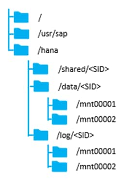
The sizing for SAP HANA file system volumes is based on the amount of memory equipped on the SAP HANA host.
Single-host solutions
The recommended, minimum disk space requirements for SAP HANA TDI installations are:
| 100 GB inclusive of space required for /usr/sap |
|
| /hana/shared |
1 × RAM or 1TB whichever is less |
| /hana/data |
1 × RAM |
| /hana/log |
512 GB |
Multi-host solutions
The recommended, minimum disk space requirements for SAP HANA TDI installations are:
| / (root) |
100 GB inclusive of space required for /usr/sap |
| /hana/shared |
1 × RAM for every 4 active HANA nodes |
| /hana/data |
1 × RAM for each active HANA node |
| /hana/log |
512 GB for each active HANA node |
Operating System
The supported operating systems for SAP HANA with Intel® Optane™ DCPMM are, as follows:
· SUSE Linux Enterprise Server for SAP Applications 15 SP1
· Red Hat Enterprise Linux for SAP HANA 8.0
High Availability
The infrastructure for an SAP HANA solution must not have single point of failure. To support high-availability, the hardware and software requirements are:
· External storage: Redundant data paths, dual controllers, and a RAID-based configuration are required
· Ethernet switches: Two or more independent switches should be used
· SAP HANA multi-host comes with integrated high-availability functionality. If an SAP HANA system is configured with a stand-by node, a failed node of SAP HANA will start on the stand-by node automatically. For automatic host failover, SAP HANA storage connector API must be properly configured for the implementation and operation of the SAP HANA.
Although not tested and validated in this design, additional high-availability solutions like SAP HANA System Replication with Linux Cluster are available as well. For detailed information, refer to the SAP HANA Administration Guide - High Availability for SAP HANA or SAP HANA Administration Guide and Configuring SAP HANA System Replication.
A high-level summary of the FlexPod Datacenter Design validation is provided in this section. Installation procedure for both, SUSE and Red Hat Linux, following best practices from Cisco, NetApp and SAP. All SAP HANA TDI phase 5 requirements are tested and passed for performance and high availability, including:
· Cisco UCS Setup and Configuration
· NetApp Setup and Configuration
· iSCSI boot option
· Operating System Configuration for SAP HANA
· Installation of SAP HANA 2.0 SPS4
· Performance Tests using SAP’s test tools
Validated hardware and software
Table 11 lists the hardware and software versions used during solution validation. It is important to note that Cisco and NetApp have interoperability matrixes that should be referenced to determine support for any specific implementation of FlexPod. Click the following links for more information:
· NetApp Interoperability Matrix Tool
· Cisco UCS Hardware and Software Interoperability Tool
Table 11 Validated hardware and software revisions
| Layer |
Device |
Image |
Comments |
| Compute |
Cisco UCS Fabric Interconnects 6454, Cisco UCS B480 M5 |
UCSM 4.0(4g) |
Includes the Cisco UCS-IOM 2408, Cisco UCS Manager, Cisco UCS VIC 1440 and Cisco UCS VIC 1480. Also valid for rack form factor Cisco UCS C480 M5 and two socket Cisco UCS blade and rack servers. |
| Network |
Cisco Nexus 9336C-FX2 Leaf Switches Cisco Nexus 9332C Spine Switches |
ACI 4.2(3l) |
APIC M2 Cluster |
| Storage |
NetApp AFF A300 |
ONTAP 9.6 with NFS v4.1 |
|
| Operating System |
|
SLES for SAP Applications 15 SP1 RHEL for SAP HANA 8.0 |
iSCSI boot |
FlexPod Datacenter with Cisco ACI provides an optimal infrastructure foundation to deploy SAP HANA be it bare metal or virtualized to implement a TDI environment. It features the latest Cisco UCS servers, Nexus fabric switches and NetApp All Flash storage. Cisco ACI and Cisco UCS has its own policy-based management in APIC and service profiles respectively providing a Unified Fabric with simple scaling, and high-performance I/O. NetApp AFF Arrays, along with ONTAP data management software defines truly unified storage that delivers the built-in storage efficiencies, integrated data protection, and intelligent management and automation.
It is validated for both SUSE Linux Enterprise Server and Red Hat Enterprise Linux operating systems. It is designed and validated using compute, network and storage best practices for high performance, scalability, and resiliency throughout the architecture. The flexibility and scalability of FlexPod also enables customers to start with a right-sized infrastructure that can ultimately grow with and adapt to their evolving business requirements.
Products and solutions
Cisco Unified Computing System
http://www.cisco.com/en/US/products/ps10265/index.html
Cisco UCS 6400 Fabric Interconnect
Cisco UCS 6400 Series Fabric Interconnects
Cisco UCS 5100 Series Blade Server Chassis
http://www.cisco.com/en/US/products/ps10279/index.html
Cisco UCS 2408 Fabric Extenders
Cisco UCS B-Series Blade Servers
http://www.cisco.com/en/US/partner/products/ps10280/index.html
Cisco UCS C-Series Rack Mount Servers
http://www.cisco.com/c/en/us/products/servers-unified-computing/ucs-c-series-rack-servers/index.html
Cisco UCS Adapters
http://www.cisco.com/en/US/products/ps10277/prod_module_series_home.html
Cisco UCS Manager
http://www.cisco.com/en/US/products/ps10281/index.html
Cisco Nexus 9000 Series Switches
http://www.cisco.com/c/en/us/products/switches/nexus-9000-series-switches/index.html
AppDynamics
https://docs.appdynamics.com/display/SAP/SAP+Monitoring+Using+AppDynamics
https://docs.appdynamics.com/display/SAP/SAP+HANA+Dashboards
NetApp ONTAP 9
http://www.netapp.com/us/products/platform-os/ontap/index.aspx
NetApp Data Management Software
http://www.netapp.com/us/products/management-software/
NetApp SnapCenter
https://www.netapp.com/us/products/backup-recovery/snapcenter-backup-management.aspx
TR-4435: SAP HANA on NetApp All Flash FAS Systems with NFS Configuration Guide
https://www.netapp.com/us/media/tr-4435.pdf
SAP HANA Backup and Recovery with SnapCenter
https://www.netapp.com/us/media/tr-4614.pdf
SAP HANA Disaster Recovery with Asynchronous Storage Replication
https://www.netapp.com/us/media/tr-4646.pdf
Integrating NetApp ONTAP systems with SAP Landscape Management
https://www.netapp.com/us/media/tr-4018.pdf
Interoperability matrixes
Cisco UCS Hardware Compatibility Matrix
https://ucshcltool.cloudapps.cisco.com/public/
NetApp Interoperability Matrix Tool
http://support.netapp.com/matrix/
SAP HANA Hardware Directory
https://www.sap.com/dmc/exp/2014-09-02-hana-hardware/enEN/index.html
Pramod Ramamurthy, Technical Marketing Engineer, Cisco Systems, Inc.
Pramod is a Technical Marketing Engineer with Cisco UCS Solutions and Performance Group. Pramod has more than 15 years of experience in the IT industry focusing on SAP technologies. Pramod is currently focusing on the Converged Infrastructure Solutions design, validation and associated collaterals build for SAP HANA.
Marco Schoen, Technical Marketing Engineer, NetApp, Inc.
Marco is a Technical Marketing Engineer with NetApp and has over 20 years of experience in the IT industry focusing on SAP technologies. His specialization areas include SAP NetWeaver Basis technology and SAP HANA. He is currently focusing on the SAP HANA infrastructure design, validation and certification on NetApp Storage solutions and products including various server technologies.
Acknowledgements
For their support and contribution to the design, validation, and creation of this Cisco Validated Design, the authors would like to thank:
· Shailendra Mruthunjaya, Cisco Systems, Inc.
· Ulrich Kleidon, Cisco Systems, Inc.