FlexPod Datacenter with Red Hat OpenShift AI for MLOps Design and Deployment Guide
Available Languages
Bias-Free Language
The documentation set for this product strives to use bias-free language. For the purposes of this documentation set, bias-free is defined as language that does not imply discrimination based on age, disability, gender, racial identity, ethnic identity, sexual orientation, socioeconomic status, and intersectionality. Exceptions may be present in the documentation due to language that is hardcoded in the user interfaces of the product software, language used based on RFP documentation, or language that is used by a referenced third-party product. Learn more about how Cisco is using Inclusive Language.
- US/Canada 800-553-2447
- Worldwide Support Phone Numbers
- All Tools
 Feedback
 Feedback
◦
Published: May 2025
![]()
In partnership with:


About the Cisco Validated Design Program
The Cisco Validated Design (CVD) program consists of systems and solutions designed, tested, and documented to facilitate faster, more reliable, and more predictable customer deployments. For more information, go to: http://www.cisco.com/go/designzone.
Artificial Intelligence (AI) and Machine Learning (ML) are driving unprecedented investment and innovation in enterprise data centers as businesses seek to leverage these technologies across a wide range of applications and quickly deliver them in production. This is particularly challenging considering that each application has its own unique set of requirements based on the specific ML use case it implements and the SLAs it must meet. The ML use case will impact several downstream decisions, such as the model type (generative or predictive or both), selection of model(s), and decisions around whether to build the models in-house or use pre-trained ones and may others. These applications will also utilize Enterprise data, which must be prepped and curated before they can be integrated, further complicating the process.
The delivery of these ML applications in production also requires extensive collaboration as well as integration of tools, processes and workflows between existing teams and newer ML and data teams. Once deployed, these applications, along with the models and data pipeline will need to be improved and maintained over the long term. Application teams will need to integrate the model delivery and data pipelines into their existing application delivery framework which may include continuous integration and continuous delivery (CI/CD), automation and other DevOps best practices. As a result, the application delivery pipeline — with integrated model and data pipelines — is significantly more challenging and complex. Scaling this environment both in terms of the number of models and the applications leveraging them, further adds to the challenges that an Enterprise faces. Gartner estimates that, on average, only 54 percent of AI projects make it from pilot to production, and so, despite the heavy investments in AI, delivering production applications with integrated models and data will continue to be a challenge for the foreseeable future.
To address these challenges and ensure successful outcomes, Enterprises need a strategic, holistic approach to accelerate and quickly operationalize AI/ML models for use by Enterprise applications. A crucial first step in addressing these challenges is implementing Machine Learning Operations (MLOps) to streamline model delivery. Unlike siloed, ad-hoc efforts that are inefficient, MLOps allows organizations to innovate, scale, and bring sustainable value to the business. MLOps uses DevOps principles to accelerate model delivery with consistency and efficiency. Like DevOps practices that integrate software development and IT operations with CI/CD to make the application delivery process more agile, MLOps bring DevOps principles used in application development to model delivery. Adopting MLOps is therefore essential for any organization seeking to scale AI/ML initiatives sustainably.
The solution in this design guide delivers a complete infrastructure stack with MLOps that Enterprises can deploy to efficiently manage, accelerate, and scale multiple AI/ML initiatives from incubation to production. The solution uses Red Hat OpenShift AI as the MLOps platform running on FlexPod baremetal infrastructure, (Cisco UCS X-Series, NetApp, and Cisco Nexus) with Red Hat Openshift to support Enterprise AI/ML initiatives at scale.
Audience
This document is intended for, but not limited to, sales engineers, technical consultants, solution architect and enterprise IT, and machine learning teams interested in learning how to design, deploy, and manage a production-ready AI/ML infrastructure for hosting machine learning models and AI-enabled applications.
Purpose of this document
This document serves as a reference architecture for MLOps using Red Hat OpenShift AI to accelerate AI/ML efforts and deliver models that application teams can use to build and deliver integrated ML applications. This document also provides design guidance for building a production-ready AI/ML infrastructure based on Red Hat OpenShift running on FlexPod datacenter infrastructure, leveraging optional NVIDIA AI Enterprise software and GPUs.
This chapter contains the following:
● Compute Unified Device Architecture
The end goal of an Enterprise’s AI/ML initiatives are to deploy ML-integrated applications that bring value to the business. Figure 1 illustrates the model delivery pipeline of an ML model before it can integrate into the application and the continuous integration and continuous delivery lifecycle that is required to maintain that model. The workflow also highlights integration of the data pipeline with the model pipeline before it is integrated into the application workflow.
Typically, for a given model, the life cycle will have the following stages which are then maintained for the lifetime of that ML model to ensure accuracy and minimize drift.
Data Pipeline – This is represented by the first box in the workflow. In this stage, data is collected and consolidated from various data sources. This is the Enterprise data that is necessary to for the ML use case in question – either for differentiation or to address the limitations that Large Language Models (LLMs) have in an Enterprise use case. Enterprises must continuously manage a steady-stream of continuously changing data from different sources and curate them for use in a model delivery pipeline. Data engineers may have to perform activities such as ingestion, exploration, labeling and preparation to deliver the curated data to the second stage in the above workflow, the model delivery or ML pipeline. This stage is part of the data delivery pipeline with a life cycle of its own and serves as input to the model workflow.
Model Delivery – This is represented by the second box in the workflow (see Figure 1). It includes the development and deployment stages of delivering a model in production, also know as model serving. The published models are made available using a standard interface (RPC, HTTPs) that applications teams can integrate into their CI/CD or development workflow to build and deliver the ML-enabled application. The model delivery pipeline is the focus of MLOps and typically involves the following stages. The next section details the ML pipelines and MLOps.
● Access ML-ready data – This is the output from the Gather and Prepare Data box in the above pipeline. It takes as input consolidated structured or unstructured data that has been cleaned, labeled, and formatted for use by ML engineers to evaluate, train and test the models. The data pipeline for AI delivers a curated dataset that serves as input to ML pipeline.
● Model Training – In this stage, data from the previous stage are used to develop, train, and test a new model from scratch or evaluate and re-train/customize a foundational model using Enterprise data. This stage involves any experimentation and evaluation work involved identify and select a model that best suits the needs of the use case in question. Other model customizations such as fine-tuning, and prompt engineering may also be done in this stage.
● Model Validation – In this stage, the model that has been selected and trained using Enterprise data is tested to ensure that it is ready for production deployment.
● Model Serving – In this stage, the model is deployed into production and available as an inferencing endpoint that applications can then use in their applications to implement the specific ML use case. Models are hosted on inferencing engines (for example, Virtual LLM) and delivered as an API endpoint accessible via a standard interface (RPC or HTTPS) by the application. The inference server or engine must meet the performance criteria of the application – however, the overall application design will determine how the inferencing engine hosting the model is deployed at scale, with resiliency.
● Automation – This stage represents the automation required to maintain the ML model with CI/CD to adapt to new data and other changes that maybe necessary based on feedback from its use in production.
● AI-Enabled Application Deployment – This stage represents the output of ML delivery pipeline which a published model for use in product. Application teams takes the delivered model and integrates it into their software development processes with CI/CD, and other DevOps and GitOps practices to deliver ML-enabled applications that implements a given ML use case. Models are continuously monitored in production with a feedback loop to continuously improve the model’s performance and accuracy.
Machine Learning Operations (MLOps) are a set of best practices to streamline and accelerate the delivery of machine learning (ML) models. The delivery of these ML models for production use or model serving is key to operationalizing AI so that Enterprises can build and deliver ML-enabled applications. Once delivered, the maintenance of the models are critical for ensuring the accuracy and reliability of model predictions and other outputs. MLOps leverages DevOps and GitOps principles to enable continuous retraining, integration, and delivery. Delivering ML-enabled applications involves new roles such as data scientists and ML engineers that weren’t part of traditional software/application development. These new roles will also require new tools and environments to do their work. As such, MLOps platforms will typically include a wide ecosystem of tools, technologies, libraries, and other components, including automation capabilities.
Automation is integral to MLOps to accelerate efforts that minimizes technical debt, enabling Enterprises to deliver and maintain models at scale. MLOps pipelines also need to continuously retrain models to keep up with everchanging data to ensure model performance. MLOps brings consistency and efficiency to the model delivery process.
In this solution, MLOps is provided by Red Hat OpenShift AI serves as the MLOps platform to streamline, scale and accelerate model delivery, with Red Hat OpenShift providing cloud-native (Kubernetes) cluster management and orchestration.
Red Hat OpenShift AI (previously known as Red Hat OpenShift Data Science or RHODS) is a flexible and scalable platform for AI/ML and MLOps that enables enterprises to create and deliver AI-enabled applications at scale. Built using open-source technologies and Red Hat OpenShift as the foundation, OpenShift AI provides a trusted, operationally consistent environment for Enterprise teams to experiment, serve models, and deliver ML-enabled applications. Red Hat OpenShift AI running on OpenShift provides a single enterprise-grade application platform for ML models and applications that use them. Data scientists, engineers, and app developers can collaborate in a single destination that promotes consistency, security, and scalability. OpenShift administrators that manage existing application environment can continue to do the same for OpenShift AI and ML workloads. This also allows application, ML, and data science teams to focus on their areas of work and spend less time managing the infrastructure.
Red Hat OpenShift AI includes key capabilities to accelerate the delivery of AI/ML models and applications in a seamless, consistent manner, at scale. The platform provides the development environment, tools, and frameworks that data scientists and machine learning teams need to build, deploy, and maintain AI/ML models in production. OpenShift AI streamlines the ML model delivery process from development to production deployment (model serving) with efficient life cycle management and pipeline automation. From the OpenShift AI console, AI teams can select from a pre-integrated, Red Hat supported set of tools and technologies or custom components that are enterprise managed, providing the flexibility that teams need to innovate and operate with efficiency. OpenShift AI also makes it easier for multiple teams to collaborate on one or more efforts in parallel.
OpenShift AI is compatible with leading AI tools and frameworks such as TensorFlow, PyTorch, and can work seamlessly with NVIDIA GPUs, to accelerate AI workloads. It provides pre-configured Jupyter notebook images with popular data science libraries. Red Hat tracks, integrates, tests, and supports common AI/ML tooling and model serving on RedHat OpenShift. The latest release of Red Hat OpenShift AI delivers enhanced support for predictive and generative AI model serving and improves efficiency of data processing and model training.
Other key features of OpenShift AI include:
● Collaborative Workspaces: OpenShift offers a collaborative workspace where teams can work together and collaborate on one or more models in parallel.
● Development Environments: ML teams can use Jupyter notebooks as a service using pre-built images, common Python libraries and open-source technologies such as TensorFlow and PyTorch to work on their models. In addition, administrators can add customized environments for specific dependencies or for additional IDEs such as RStudio and VSCode.
● Model Serving at scale: Multiple Models can be served for integration into intelligent AI-enabled applications using inferencing servers (for example, Intel OpenVINO, NVIDIA Triton) using GPU or CPU resources provided by the underlying OpenShift cluster without writing a custom API server. These models can be rebuilt, redeployed, and monitored by making changes to the source notebook.
● Support for enhanced model serving with the ability to use multiple model servers to support both predictive and GenAI, including support for KServe, a Kubernetes custom resource definition that orchestrates serving for all types of models, vLLM and text generation inference server (TGIS), serving engines for LLMs and Caikit-nlp-tgis runtime, which handles natural language processing (NLP) models and tasks. Enhanced model serving allows users to run predictive and GenAI on a single platform for multiple use cases, reducing costs and simplifying operations. This enables out-of-the-box model serving for LLMs and simplifies the surrounding user workflow.
● Innovate with open-source capabilities: Like Red Hat OpenShift, OpenShift AI integrates with open-source tools and leverages a partner ecosystem to enhance the capabilities of the platform, minimizing vendor lock-ins.
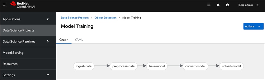
● Data Science Pipelines for GUI-based automation using OpenShift pipelines: OpenShift AI leverages OpenShift pipelines to automate ML workflow using an easy to drag-and-drop web UI as well as code driven development of pipelines using a Python SDK.
● Model monitoring visualizations for performance and operational metrics, improving observability into how AI models are performing.
● New accelerator profiles enable administrators to configure different types of hardware accelerators available for model development and model-serving workflows. This provides simple, self-service user access to the appropriate accelerator type for a specific workload.
By using Red Hat OpenShift AI, enterprises can manage and maintain AI/ML models and the applications using the same models on a single, unified platform and simplify overall management of the environment.
Red Hat OpenShift is a leading enterprise application platform that brings together a comprehensive set of tools and services that streamline the entire application lifecycle, from development to delivery and maintenance of application workloads. It allows organizations to modernize their applications and includes multiple advanced open-source capabilities that are tested and integrated with the underlying certified Kubernetes environment, such as Red Hat OpenShift Serverless, Red Hat OpenShift Pipelines and Red Hat OpenShift GitOps. Red Hat OpenShift offers a complete set of services that helps developers code applications with speed, flexibility, and efficiency. OpenShift is designed to support anywhere from a few machines and applications to thousands of machines and applications and allows enterprises to extend their application environment from on-prem to public cloud and multi-cloud environments.
Figure 2 shows the high-level architecture of Red Hat Openshift.
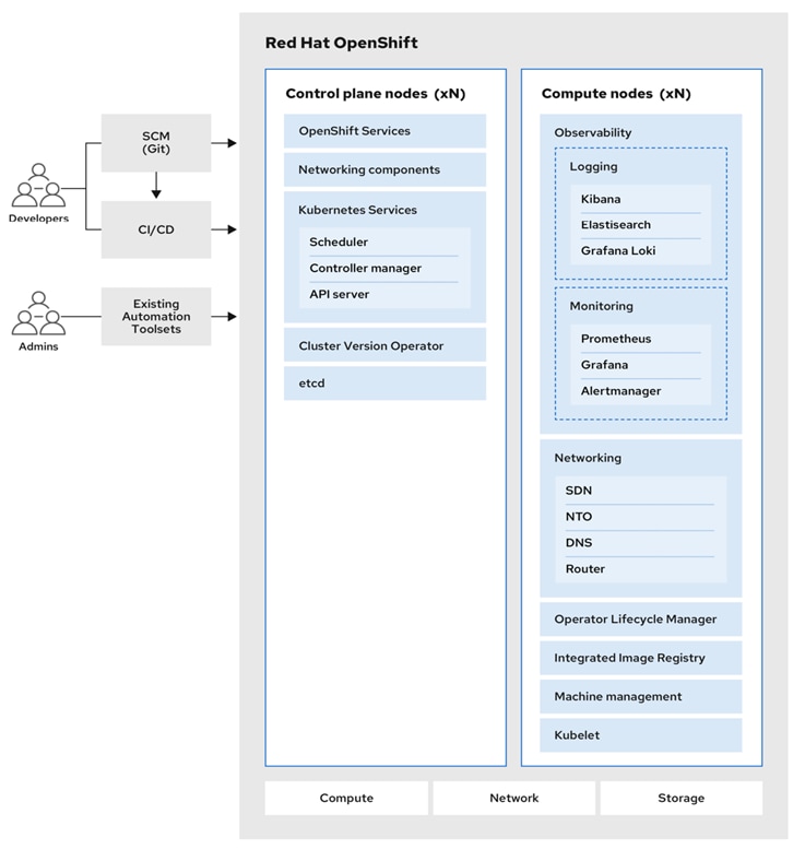
Red Hat OpenShift uses Red Hat Enterprise Linux CoreOS (RHCOS), a container-oriented operating system that is specifically designed for running containerized applications and provides several tools for fast installation, Operator-based management, and simplified upgrades. RHCOS includes:
● Ignition, which is used as a first-boot system configuration for initially bringing up and configuring machines.
● CRI-O, a Kubernetes native container runtime implementation that integrates closely with the operating system to deliver an efficient and optimized Kubernetes experience. CRI-O provides facilities for running, stopping, and restarting containers.
● Kubelet, the primary node agent for Kubernetes that is responsible for launching and monitoring containers.
Note: The control plane nodes in Red Hat OpenShift must run RHCOS, but Red Hat Enterprise Linux (RHEL) can be used in worker or compute nodes.
AI/ML workloads, like many modern applications, uses containers and Kubernetes (K8s) orchestration as the de facto development environment for model development and AI-enabled applications. Kubernetes offer several benefits, but one key attribute is its extensibility. Kubernetes provides an Operator framework that vendors and open-source communities can use to develop and deploy self-contained operators that extend the capabilities of the K8s cluster. These operators generally require minimum provisioning and are usually self-managed with automatic updates (unless disabled) and handle life-cycle management. Kubernetes operators are probably the closest thing to an easy-button in infrastructure provisioning (short of IaC). In the Red Hat OpenShift environment that this solution uses, it is even easier to deploy and use operators. Red Hat OpenShift provides an embedded OperatorHub, directly accessible from the cluster console. The Red Hat OperatorHub has hundreds of Red Hat and community certified operators that can be deployed with a few clicks.
To support AI/ML workloads and OpenShift AI, the following Red Hat OpenShift operators are deployed in this solution to enable GPU, storage, and other resources:
● Red Hat Node Feature Discovery Operator to identify and label hardware resources (for example, NVIDIA GPUs)
● NVIDIA GPU Operator deploys and manages the GPU resource on a Red Hat OpenShift cluster (for example, Guest OS vGPU drivers)
● NetApp Trident Operator for managing container-native persistent storage required for model delivery, backed by NetApp ONTAP storage – file, block, and object store.
● Red Hat OpenShift AI Operator deploys OpenShift AI on any OpenShift cluster
For more information on Red Hat OpenShift Operators, see: https://www.redhat.com/en/technologies/cloud-computing/openshift/what-are-openshift-operators.
NVIDIA AI Enterprise (NVAIE) is a comprehensive suite of enterprise-grade, cloud-native software, hardware, and support services offered by NVIDIA for artificial intelligence (AI) and machine learning (ML) applications. NVIDIA describes NVAIE as the “Operating System” for enterprise AI. NVIDIA AI Enterprise includes key enabling technologies for rapid deployment, management, and scaling of AI workloads. It includes NVIDIA GPUs, Kubernetes Operators for GPUs, virtual GPU (vGPU) technology, and an extensive software library of tools and frameworks optimized for AI that make it easier for enterprises to adopt and scale AI solutions on NVIDIA infrastructure.
NVAIE can be broadly categorized into Infrastructure Management, AI Development, and Application Frameworks optimized for AI. For more details on NVAIE, see: https://www.nvidia.com/en-us/data-center/products/ai-enterprise/.
This solution optionally leverages the NVIDIA AI Enterprise Software suite (along with other complementary partner components) to extend and operationalize a robust, production-ready FlexPod AI infrastructure to support a range of use cases.
NVIDIA’s GPU operator for Red Hat OpenShift provides seamless deployment and management of GPU resources and CUDA libraries for optimal use of GPU to support various AI/ML use cases. NVIDIA AI Enterprise can be used to extend those capabilities even further.
NVAIE is a licensed software from NVIDIA that must be certified to run on the infrastructure servers. For more information on the licensing and certification, click the links below:
● Certification: https://www.nvidia.com/en-us/data-center/products/certified-systems/
For additional information on NVIDIA AI Enterprise, go to: https://www.nvidia.com/.
The NVIDIA L40S GPU Accelerator is a full height, full-length (FHFL), PCI Express Gen4 graphics solution based on the NVIDIA Ada Lovelace architecture. The NVIDIA L40S GPU delivers acceleration for the next generation of AI-enabled applications—from gen AI, LLM inference, small-model training and fine-tuning to 3D graphics, rendering, and video applications.
Note: NVIDIA L40S GPUs does not support Multi-Instance GPUs or MIG that allows a physical GPU to be partitioned into multiple, smaller instances.
Table 1. NVIDIA L40S – Technical Specification
| NVIDIA L40S PCIe 40GB |
|
| GPU Architecture |
NVIDIA Ada Lovelace architecture |
| GPU Memory |
48GB GDDR6 with ECC |
| Memory Bandwidth |
864GB/s |
| Interconnect Interface |
PCIe Gen4 x16: 64GB/s bidirectional |
| NVIDIA Ada Lovelace Architecture-Based CUDA® Cores |
18,176 |
| NVIDIA Third-Generation RT Cores |
142 |
| NVIDIA Fourth-Generation Tensor Cores |
568 |
| RT Core Performance TFLOPS |
209 |
| FP32 TFLOPS |
91.6 |
| TF32 Tensor Core TFLOPS |
183 I 366* |
| BFLOAT16 Tensor Core TFLOPS |
362.05 I 733* |
| FP16 Tensor Core |
362.05 I 733* |
| FP8 Tensor Core |
733 I 1,466* |
| Peak INT8 Tensor TOPS |
733 I 1,466* |
For more information, see: https://resources.nvidia.com/en-us-l40s/l40s-datasheet-28413
Compute Unified Device Architecture
Compute Unified Device Architecture (CUDA) is a parallel computing platform and application programming interface (API) model from NVIDIA that enables general purpose computing on GPUs that were originally designed for graphics. CUDA excels in complex mathematical computations and data processing tasks that can run on thousands of GPU cores in parallel, making it well suited for compute-intensive AI/ML use cases. It also provides memory management to enable efficient data transfers between the CPU and GPU. NVIDIA’s CUDA Toolkit provides developers with the software tools and libraries for developing GPU-accelerated applications that harness the parallel processing capabilities of the GPUs. It includes a compiler, debugger, runtime libraries, and other tools that simplify the process of GPU programming.
The FlexPod Datacenter is a reference architecture for hosting a wide range of enterprise workloads on both virtualized baremetal infrastructure in enterprise data centers. Cisco Validated Designs (CVDs) for FlexPod Datacenter solutions provide design and implementation guidance as well as Infrastructure as Code (IaC) automation using Red Hat Ansible to accelerate enterprise data center infrastructure deployments. The designs incorporate product, technology, and industry best practices to deliver a highly-available, scalable, and flexible architecture.
The key infrastructure components for compute, network, and storage in a FlexPod Data center solution are:
● Cisco Unified Computing System (Cisco UCS) Infrastructure
● Cisco Nexus 9000 switches
● Cisco MDS 9000 SAN switches (when using Fibre Channel SAN)
● NetApp AFF/FAS/ASA storage
FlexPod designs are flexible and can be scaled-up or scaled-out without sacrificing feature/functionality. FlexPod solutions are built and validated in Cisco labs to ensure interoperability and minimize risk in customer deployments. CVD solutions enables enterprise IT teams to save valuable time that would otherwise be spent on designing and integrating the solution in-house.
All FlexPod CVDs are available in the Cisco Design Zone here: https://www.cisco.com/c/en/us/solutions/design-zone/data-center-design-guides/flexpod-design-guides.html
The FlexPod AI solution in this document serves as a foundational infrastructure architecture to deliver a robust, scalable design for compute, networking, storage and GPU options for Enterprise AI initiatives. Using this solution, enterprises can quickly start on their AI journey and scale incrementally as the enterprise needs grow.
The FlexPod AI design adds the following components to the foundational architecture documented in the foundational FlexPod Datacenter Baremetal infrastructure solution.
● Cisco UCS X440p PCIe nodes, capable of hosting up to four GPUs (only some models). Each PCIe node is paired with a Cisco UCS compute node, specifically the Cisco UCS X210c M7 server but a Cisco UCS X410c can also be used with UCS. Connectivity between the compute node and PCIe node requires a PCIe mezzanine card on the compute node and a pair of X-Fabric modules on the Cisco UCS X9508 server chassis.
● NVIDIA GPUs (L40S-48GB) for accelerating AI/ML workloads and model delivery pipeline.
● Red Hat OpenShift for Kubernetes based container orchestration and management.
● NetApp Trident for persistent storage (backed by NetApp ONTAP Storage).
● Red Hat OpenShift AI for MLOps.
● Object store provided by NetApp AFF storage
Note: Cisco UCS-X supports a range of CPU and GPU options from Intel, AMD and NVIDIA for accelerating AI/ML workloads.
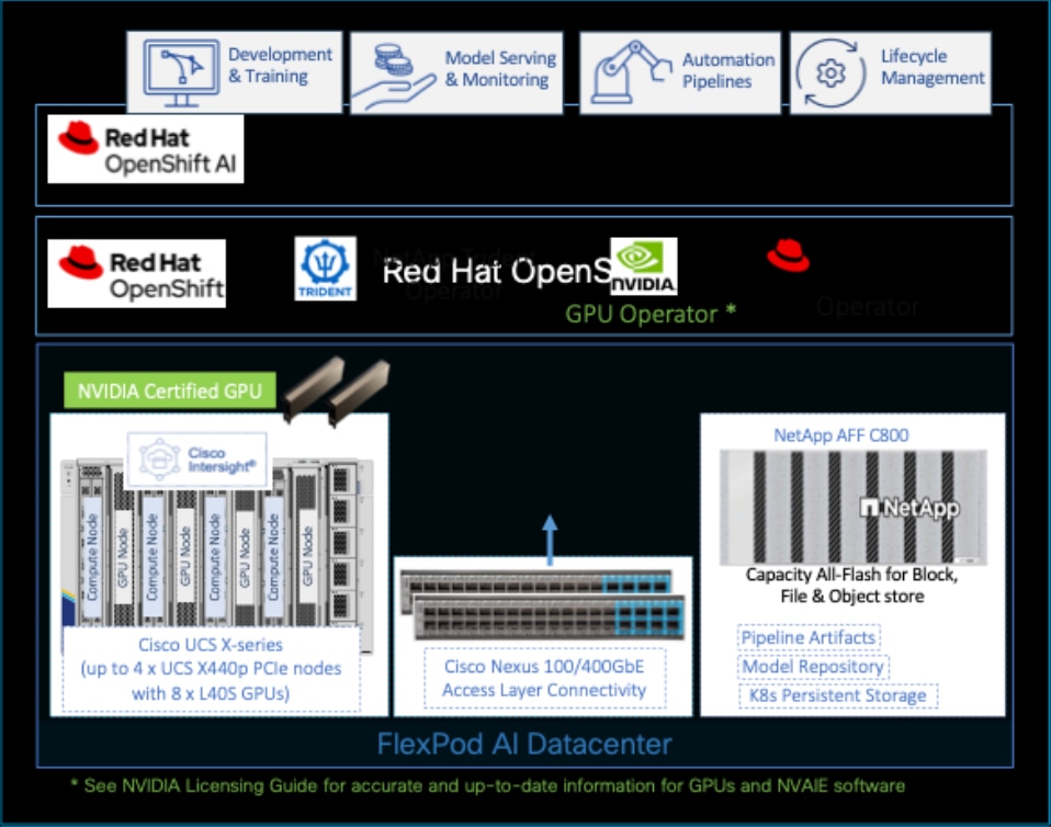
Figure 3 shows the components validated in this solution for hosting AI/ML workloads.
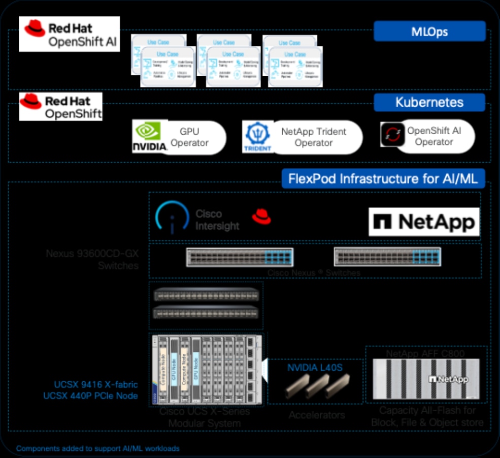
The following sections provide a brief overview of the new components added in this solution to support AI/ML workloads.
Cisco UCS-X 9508 Server Chassis
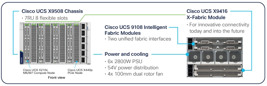
Cisco UCS X9508 is a 7RU chassis with eight slots that can support up 4 PCIe nodes, each paired with a compute node for a total of 4 compute nodes as shown in Figure 4.
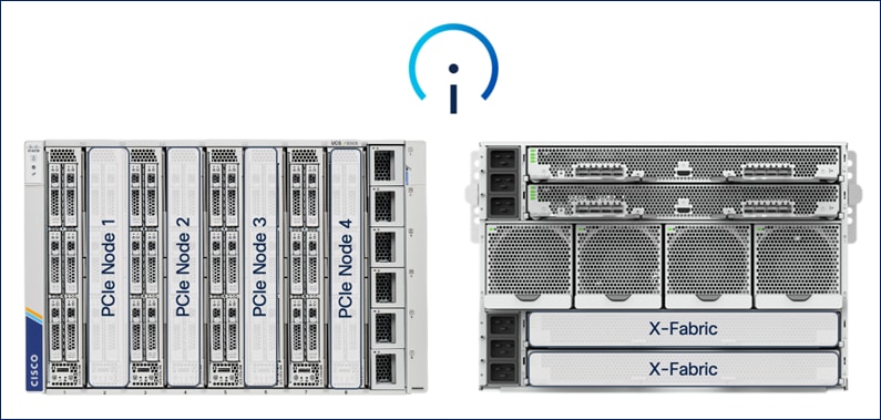
PCIe or GPU nodes must be deployed in a slot adjacent to the compute node which will enable the compute node to automatically recognize and use the adjacent PCIe node as an extension of itself. To enable this connectivity between GPUs in PCIe nodes and the compute nodes, the following additional components are required to enable PCIe Gen4 connectivity between compute and GPU nodes.
● PCIe mezzanine card on the compute node (UCSX-V4-PCIME)
● Pair of Cisco UCS X9416 X-Fabric Modules deployed to the back of Cisco UCS X-series server chassis (UCSX-F-9416) - see Figure 5
The X-Fabric modules provide a redundant PCIe 4 fabric to enable PCIe connectivity between compute and PCIe/GPU nodes.
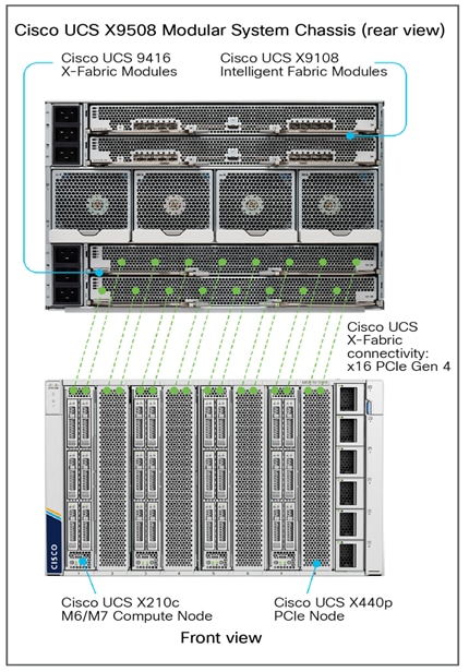
The Cisco UCS X9508 Chassis is midplane-less design, provides fewer obstructions for better airflow. The vertically oriented Cisco UCS X210c or X410c compute nodes and the PCIe nodes connect directly to horizontally oriented X-Fabric modules, located at the back of the chassis (see Figure 5). The innovate design enables Cisco UCS X-Series to easily upgrade to newer technologies and hardware without requiring forklift upgrades.
Cisco UCS X440p PCIe Node and GPUs
The Cisco UCS X440p PCIe node (UCSX-440P-U) is the first PCIe node supported on a Cisco UCS X-Series fabric. It is part of the Cisco UCS-X Series modular system, managed using Cisco Intersight and integrated to provide GPU acceleration for workloads running on Cisco UCS compute (X210c, X410c) nodes. GPUs can be installed on the PCIe node and then paired with a compute node in an adjacent slot to support AI/ML, VDI, and other workloads that require GPU resources. GPUs. The PCIe node requires riser cards to support different GPU form factors, either full height, full length (FHFL) or half height, half length (HHHL) GPUs as outlined below:
● Riser Type A: Supports 1 x 16 PCIe connectivity for FHFL GPUs (UCSX-RIS-A-440P)
● Riser Type B: Supports 1 x 8 PCIe connectivity for HHHL GPUs (UCSX-RIS-B-440P)
Each PCIe node supports a maximum of two riser cards, with each riser card capable of supporting up to:
● 1 x 16 FHFL dual slot PCIe cards, one per riser card for a total of two FHFL cards
● 1 x 8 HHHL single slot PCIe card, two per riser card for a total of four HHHL cards
Note: Each PCIe node must have the same type of risers and GPUs. You cannot mix and match riser types and GPU types in the same PCIe node.
The NVIDIA L40S-48GB GPU (UCSX-GPU-L40S) deployed in this solution is a FHFL GPU and uses the Type A riser card.
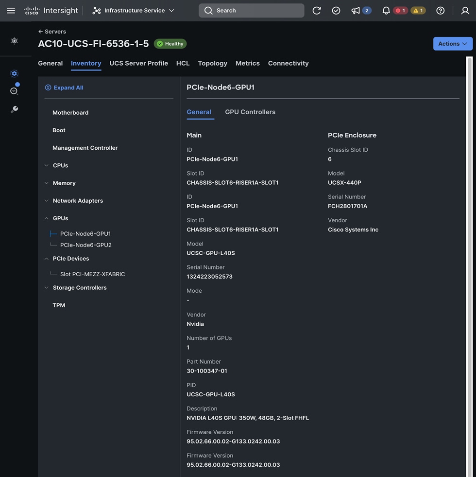
PCIe or GPU nodes must be deployed in a slot adjacent to the compute node and the compute node will automatically recognize and use the adjacent PCIe node as an extension of itself in Cisco Intersight as shown below. The compute node does require a mezzanine card for connecting to the PCIe fabric and node hosting GPUs as shown in the figure below. The figure also shows PCIe node is in slot 6 with two L40S GPUs, as indicated by the node name: PCIe-Node6-GPU-1, -2 with compute node in slot 5.
As stated earlier, each PCIe node allows you to add up to four HHHL GPUs to accelerate workloads running on either a Cisco UCS X210c or Cisco UCS X410c compute node. This provides up to 16 GPUs per chassis. As of the publishing of this document, the following GPU models are supported on a Cisco UCS X440p PCIe node.
Table 2. GPU Options on Cisco UCS X-Series Server System
| GPU Model |
GPUs Supported per PCIe node |
GPUs Supported on |
| NVIDIA H100 NVL Tensor Core GPU |
Max of 2 |
Max of 8 |
| NVIDIA H100 Tensor Core GPU |
Max of 2 |
Max of 8 |
| NVIDIA L40S GPU |
Max of 2 |
Max of 8 |
| NVIDIA L4 Tensor Core GPU |
Max of 4 |
Max of 16 |
| NVIDIA A100 Tensor Core GPU |
Max of 2 |
Max of 8 |
| NVIDIA A16 GPU |
Max of 2 |
Max of 8 |
| NVIDIA A40 GPU |
Max of 2 |
Max of 8 |
| NVIDIA T4 Tensor Core GPUs |
Max of 4 |
Max of 24* |
| Intel® Data Center GPU Flex 140 |
Max of 4 |
Max of 24* |
| Intel Data Center GPU Flex 170 |
Max of 2 |
Max of 8 |
| AMD MI210 GPU |
Max of 2 |
Max of 8 |
*Using the optional front mezzanine GPU adapter (UCSX-X10C-GPUFM-D) on Cisco UCS X210c compute node.
If additional GPUs are needed, up to two GPUs can be added using an optional GPU front mezzanine card on the Cisco UCS X210c or Cisco UCS X410c compute nodes. Only two GPU models are currently supported in this configuration but enables up to have up to 24 GPUs per chassis. Product IDs for enabling GPU acceleration components on Cisco UCS-X are summarized in Table 3.
Table 3. Product IDs for GPU acceleration using PCIe Node
| Component |
PID |
| UCS X-Series Gen 4 PCIe node |
UCSX-440P-U |
| Riser A for 1x dual slot GPU per riser, 440P PCIe node
● Riser 1A (controlled with CPU1 on UCS X210c)
● Riser 2A (controlled with CPU2 on UCS X210c)
|
UCSX-RIS-A-440P |
| Riser B for 2x single slot GPUs per riser, 440P PCIe node
● Riser 1B (controlled with CPU1 on UCS X210c)
● Riser 2B (controlled with CPU2 on UCS X210c)
|
UCSX-RIS-B-440P |
| UCS PCI Mezz card for X‐Fabric connectivity |
UCSX-V4-PCIME |
| UCS X-Fabric module for UCS-X9508 chassis |
UCSX-F-9416 |
| NVIDIA A16 GPUs, 250W, 4x16GB |
UCSX-GPU-A16 |
| NVIDIA A40 GPUs RTX, PASSIVE, 300W, 48GB |
UCSX-GPU-A40 |
| NVIDIA T4 Tensor Core GPUs 75W, 16GB |
UCSX-GPU-T4-16 |
| NVIDIA H100 Tensor Core GPU, 350W, 80GB (2-slot FHFL GPU) |
UCSX-GPU-H100-80 |
| NVIDIA L40 GPU, 300W, 48GB |
UCSX-GPU-L40S |
| NVIDIA L4 Tensor Core GPU, 70W, 24GB |
UCSX-GPU-L4 |
For NVIDIA GPUs, see NVIDIA AI Enterprise Software Licensing guide for up-to-date licensing and support information: https://resources.nvidia.com/en-us-nvaie-resource-center/en-us-nvaie/nvidia-ai-enterprise-licensing-pg?lb-mode=preview
NetApp Trident for Kubernetes Persistent Storage
NetApp Trident is an open-source, fully supported storage orchestrator for containers created by NetApp. It has been designed from the ground up to help you meet your containerized applications persistence demands using industry-standard interfaces, such as the Container Storage Interface (CSI). With Trident, microservices and containerized applications can take advantage of enterprise-class storage services provided by the full NetApp portfolio of storage systems. In a FlexPod environment, Trident is utilized to allow end users to dynamically provision and manage persistent volumes for containers backed by FlexVols and LUNs hosted on ONTAP-based products such as NetApp AFF and FAS systems.
Trident deploys (see Figure 6) as a single Trident Controller Pod and one or more Trident Node Pods on the Kubernetes cluster and uses standard Kubernetes CSI Sidecar Containers to simplify the deployment of CSI plugins. Kubernetes CSI Sidecar Containers are maintained by the Kubernetes Storage community.
Kubernetes node selectors and tolerations and taints are used to constrain a pod to run on a specific or preferred node. You can configure node selectors and tolerations for controller and node pods during Trident installation.
● The controller plugin handles volume provisioning and management, such as snapshots and resizing.
● The node plugin handles attaching the storage to the node.
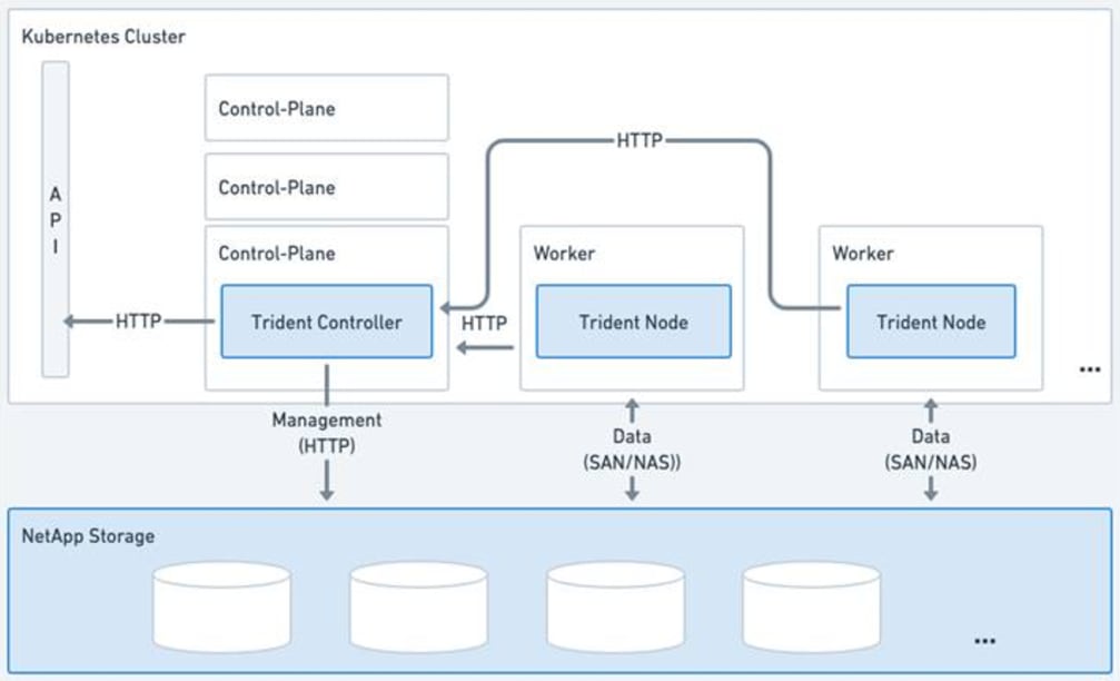

In this solution, NetApp Trident dynamically provides K8s native persistent storage using both NFS file and iSCSI/NVMe-TCP block storage hosted on a NetApp AFF storage.
NetApp ONTAP S3
With the growing demand for S3-compatible storage, ONTAP extended its support to include an additional scale-out storage option for S3. Capitalizing on ONTAP's robust data management framework, ONTAP S3 provides S3-compatible object storage capabilities, allowing data to be represented as objects within ONTAP-powered systems, including AFF and FAS. Beginning with ONTAP 9.8, you can enable an ONTAP Simple Storage Service (S3) object storage server in an ONTAP cluster, using familiar manageability tools such as ONTAP System Manager to rapidly provision high-performance object storage for development and operations in ONTAP and taking advantage of ONTAP's storage efficiencies and security.

Solution Design
This chapter contains the following:
The FlexPod Datacenter for AI with Red Hat OpenShift AI solution aims to address the following design goals:
● Best-practices based design for AI/ML workloads, incorporating product, technology, and industry best practices.
● Simplify and streamline operations for AI/ML. Ease integration into existing deployments and processes.
● Flexible design with options for tools, technologies and individual components and sub-systems used in the design can be modified to adapt to changing requirements (for example, storage access, network design)
● Modular design where sub-system components (for example, links, interfaces, model, platform) can be expanded or upgraded as needed.
● Scalable design: As deployments grow, FlexPod Datacenter can be scaled up or out to meet enterprise needs. Each FlexPod Datacenter deployment unit can also be replicated as needed to meet scale requirements.
● Resilient design across all layers of the infrastructure with no single point of failure.
The following sections explain the solution architecture and design that meets these design requirements.
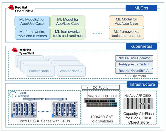
A high-level design of the FlexPod Datacenter AI solution using Red Hat OpenShift AI is shown in Figure 9.
The solution provides a foundational infrastructure design for AI using NVIDIA GPUs, NetApp Storage, Red Hat OpenShift, and MLOps provided by Red Hat OpenShift AI.
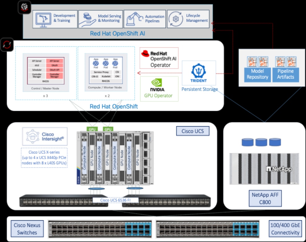
The high-level infrastructure design and topology built in Cisco labs for validating this FlexPod AI Datacenter infrastructure with Red Hat OpenShift AI is shown in Figure 10.
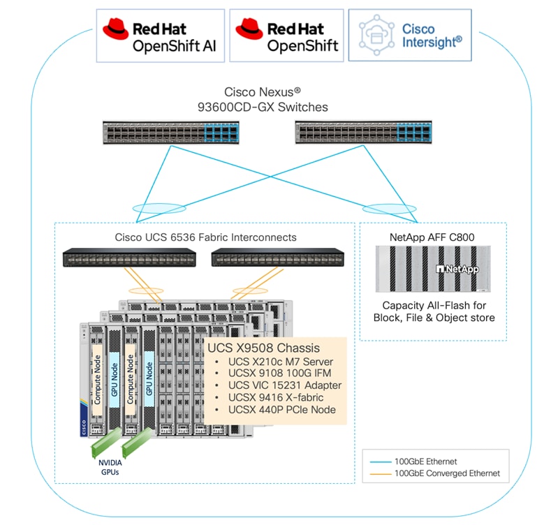
The FlexPod Datacenter infrastructure in this solution is an end-to-end 100Gb Ethernet design using NFS file and block (iSCSI, NVMe-TCP) storage hosted on NetApp AFF C-series storage. The solution provides an OpenShift Kubernetes (K8s) infrastructure for hosting cloud-native application workloads and ML workloads. The Openshift is running on Cisco UCS baremetal servers, specifically Cisco UCS X210C M7 servers with the latest Intel processors. Cisco UCS infrastructure and NetApp storage use multiple virtual port channels (VPCs) to connect to a pair of top-of-rack Cisco Nexus 9000 series switches. The access layer switches can use either multiple 100GbE or 400GbE uplinks to connect into the larger data center fabric. The solution incorporates design, technology, and product best practices to deliver a highly scalable and flexible architecture with no single point of failure.
To support Enterprise AI/ML initiatives and model delivery efforts, FlexPod AI extends the FlexPod Datacenter design as outlined in the upcoming sections to deliver a robust infrastructure design with GPU acceleration.
Cisco UCS servers with GPU nodes and NVIDIA GPUs
The design uses the Cisco UCS X-Series server chassis with NVIDIA GPUs to provide the compute and GPU resources in the solution. The Cisco UCS X9508 server chassis is a 7RU chassis with eight slots where Cisco UCS servers and PCIe nodes can be deployed with GPUs to provide a total of 8 FHFL GPUs or 16 HHHL GPUs per chassis. The Cisco UCS X9508 supports up to four PCIe nodes, with each PCIe node paired with a compute node, either a Cisco UCS X210c or X410c server. This design was validated using NVIDIA L40S-48GB GPUs, with two NVIDIA L40S GPUs installed on each GPU worker node. Alternatively, Cisco UCS C-Series Rackmount Servers can also be used. A Cisco UCS C-Series M7 server with Intel processors can support up to 3 x L40S GPUs.
Cisco UCS X-Fabric Technology
To support GPU acceleration on Cisco UCS X-Series systems, Cisco’s first generation UCS X-fabric technology, a pair of Cisco UCS X9416 Fabric modules are deployed to enable PCIe connectivity between UCS servers and UCS X440p PCIe nodes housing NVIDIA GPUs. The first-generation X-fabric supports 32 lanes of PCIe Gen 4 connectivity to each compute node, enabling each server to access a PCIe node, housing either 4 HHHL GPUs (for example, L4) or 2 FHFL GPUs (for example, L40S). Figure 11 shows the X-fabric modules and the connectivity between each compute node and the x440p PCIe node in the adjacent slot.
Note: Each UCS compute server can only access adjacent x440p GPUs through the X-Fabric.
The hardware components and connectivity between them are shown in Figure 12.
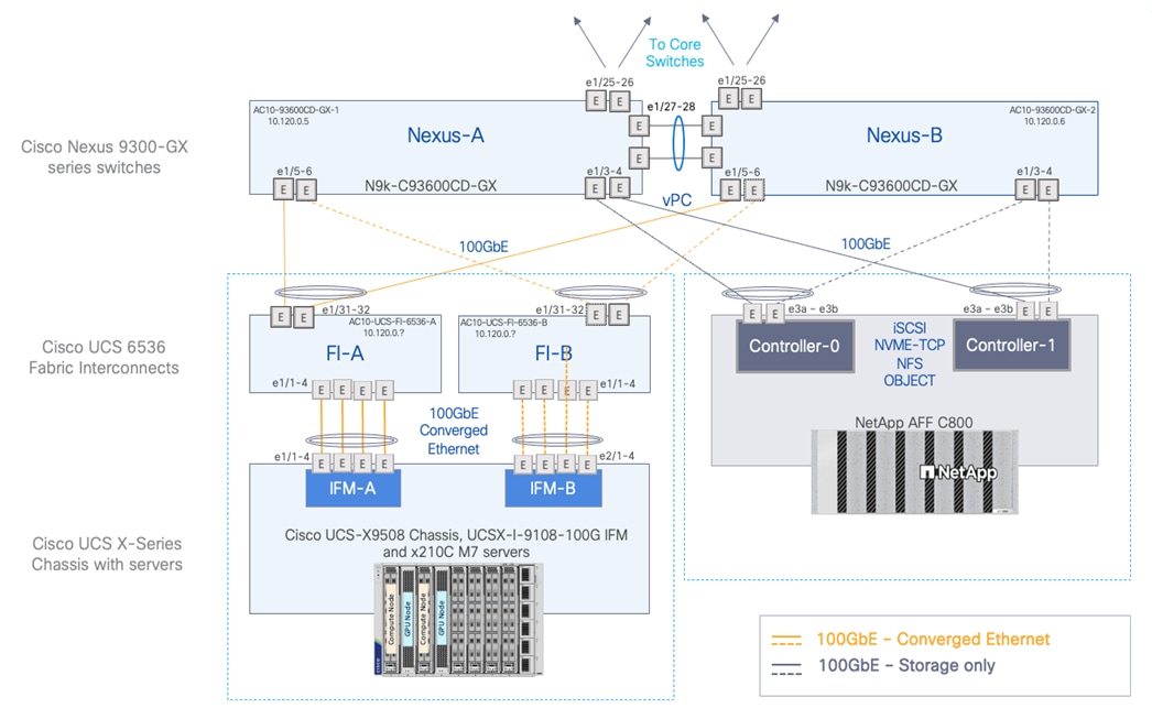
● A Cisco UCS 9508 chassis with at least 5 x Cisco UCS X210 M7 servers are connected using 100GbE IFM modules to Cisco UCS Fabric Interconnects, deployed in Intersight Managed Mode (IMM). 4 x 100GbE links from each IFM connect are bundled in a port-channel and connected to each Fabric Interconnect to provide an aggregate bandwidth of 800Gbps to the chassis with up to 8 UCS compute servers.
● Two Cisco Nexus 93600CD-GX 100/400GbE Switches in Cisco NX-OS mode provide top-of-rack switching. The fabric interconnects use multiple 100GbE links to connect to the Nexus switches in a VPC configuration.
● At least two 100 Gigabit Ethernet ports from each FI, in a port-channel configuration are connected to each Nexus 93600CD-GX switch.
● One NetApp AFF C800 HA pair connects to the Cisco Nexus 93600CD-GX Switches using two 100 GE ports from each controller configured as a Port-Channel.
● The high-performance servers are deployed as OpenShift compute nodes and booted using the Assisted Installer deployed RHCOS image on local M.2 boot drives in a RAID1 configuration. The persistent storage volumes are provisioned on the NetApp AFF C800 and accessed using NFS NAS storage, iSCSI and NVMe-TCP storage. ONTAP S3 object storage is also provisioned to store OpenShift AI models, artifacts, and other data.
● Two of the Cisco UCS X210C M7 servers in Cisco UCS X9508 Chassis are paired with Cisco UCS X440p PCIe nodes, with each PCIe node housing 2 x NVIDIA L40S GPUs.
● Each UCS M7 server is equipped with a Cisco VIC 15231 that provides 2 x 100GbE ports for 200Gbps of bandwidth from each server to the chassis.
Cisco UCS Server Networking Design
Each server is deployed with multiple virtual NICs (vNICs) and VLANs using Cisco Intersight server profiles as shown in Figure 13. Different vNIC configurations are used on OpenShift control and worker nodes.
The vNICs configuration on worked nodes are for power management, OpenShift cluster networking and storage access as outlined below:
● IB-MGMT (Optional): One vNIC and VLAN with fabric failover enabled on UCS Fabric Interconnects (FI) for in-band power management (for example, IPMI). Alternatively, you can CLUSTER-MGMT vNIC for this.
● CLUSTER-MGMT: One vNIC and VLAN with fabric failover enabled on UCS Fabric Interconnects for all OpenShift cluster networking. This includes both pod and machine networks. The default cluster networking in OpenShift, i.e. Open Virtual Networking (OVN) is used in this solution.
● iSCSI-A, iSCSI-B: Two vNICs and VLANs, one path through each UCS FI for iSCSI storage access.
● NVMe-TCP-A, NVMe-TCP-B: Two VLANs, one path through each UCS FI for NVMe over TCP storage access. These are tagged VLANs using iSCSI-A and iSCSI-B vNICs.
● NFS: One vNIC and VLAN for accessing NFS filesystems, with fabric failover enabled on UCS FIs.
● OBJ: One vNIC and VLAN for accessing S3-compatible object store hosted on NetApp storage, with fabric failover enabled on UCS FIs.
Note: Cisco UCS FI Fabric failover is recommended on non-ISCSI and NVMe-TCP interfaces versus NIC bonding at the operating system level due to the complexity involved. With fabric failover, the management and failover is handled by the Cisco FIs, by enabling it in the vNIC template and LAN connectivity policy used in the server profile template used to provision the servers. This enables it to be deployed with ease without compromising on resiliency.
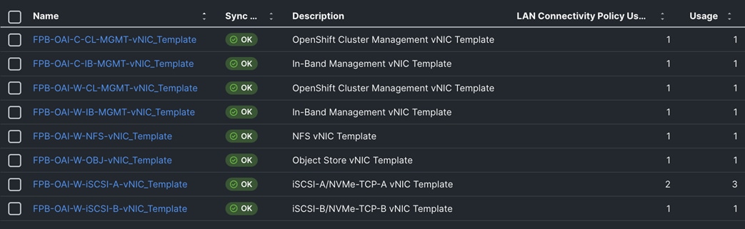
The OpenShift Control node servers in the design are only provisioned for the first two vNICs in the above list. All vNICs are configured using vNIC templates. The vNIC Template used for control (-C) and worker (-W) nodes are shown in Figure 14.
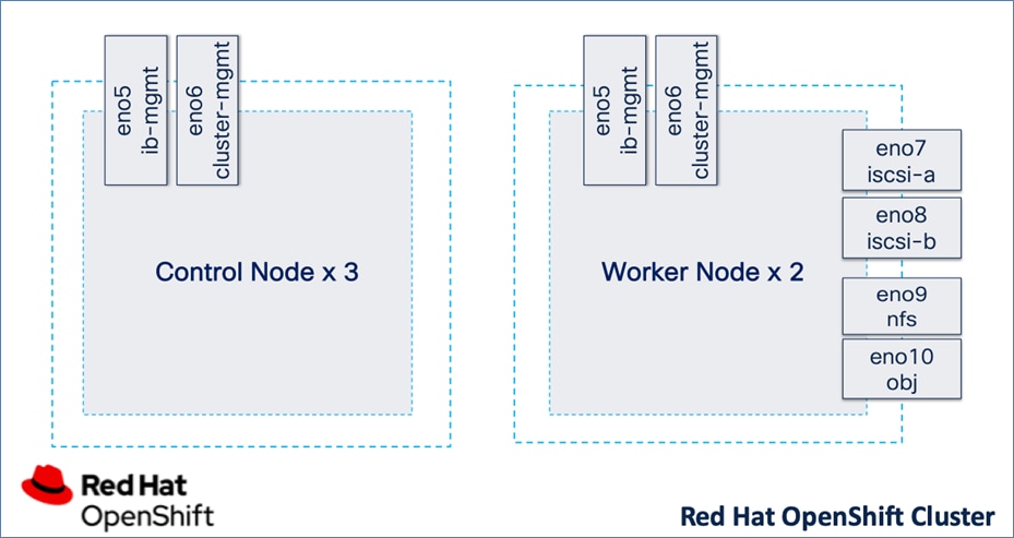
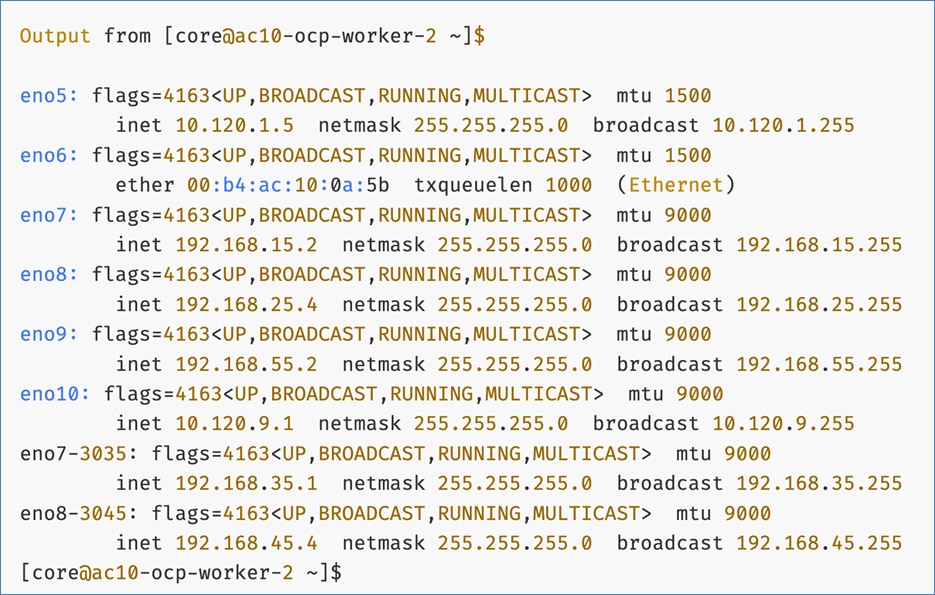
The vNIC configuration on a given UCS server worker node, derived from the above worker node (-W) templates are shown in the figure below. The vNICs name includes the OpenShift interface numbering which starts with ‘eno5’.

Storage Design
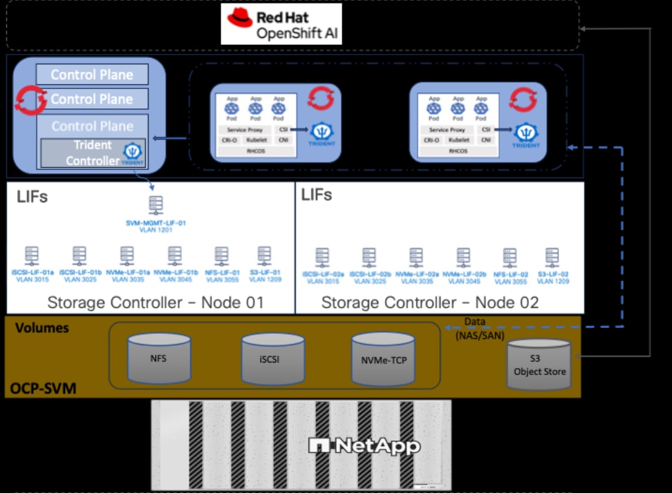
The storage is set up with NFS, iSCSI, NVMe-TCP, and S3 protocols, each having VLAN and LIF (see Figure 15). NetApp Trident will handle dynamic storage orchestration for Red Hat OpenShift workloads. Trident can be configured with various storage backends based on requirements. For this solution, NAS, and SAN backends were used. Trident will provision PVCs based on the configured storage class and map them to the containers.
OpenShift AI requires S3-compatible object stores to store artifacts, logs, immediate results used by data science pipelines, and single- or multi-model serving platforms for deploying stored models. ONTAP S3 is configured to provide object stores and is directly presented to OpenShift AI for use in this solution. Following NetApp’s best practices, S3 LIFs are configured on both nodes.
OpenShift Design
Most machine learning (ML) models, frameworks, and test applications from popular sources like Hugging Face and NVIDIA GPU Cloud (NGC) are typically available as pre-packaged containers. The AI/ML ecosystem has also embraced Kubernetes, making containers the primary environment for the development and deployment of AI/ML workloads.
Given these factors and the need for an enterprise-class platform, this solution leverages OpenShift to offer enterprises a secure, robust Kubernetes orchestration and container management platform for developing, deploying, and managing cloud-native applications and ML workloads. By using OpenShift as the foundation for ML model delivery, including applications that integrate production ML models, enterprises can benefit from a unified platform for their AI/ML initiatives.
By combining OpenShift with OpenShift AI (see next section), OpenShift uniquely simplifies and accelerates projects with clear separation of functions. OpenShift administrators can continue to manage Kubernetes infrastructure administration, including provisioning GPUs, role-based access control, and resource utilization, while ML engineers can focus on ML delivery without worrying about the underlying infrastructure.
Red Hat offers multiple options for deploying OpenShift clusters, including both on-premises and SaaS solutions for connected and disconnected environments. These deployments can be managed using Advanced Cluster Management (ACM) or the cloud-based Red Hat Hybrid Cloud Console (HCC). In this solution, Red Hat OpenShift is deployed as a self-managed service using the Red Hat-recommended Assisted Installer from the Hybrid Cloud Console.
Red Hat recommends using the Assisted Installer for several reasons – one advantage being that it eliminates the need for a separate bootstrap machine during installation. Instead, the Assisted Installer uses one of the cluster nodes to manage the bootstrapping of other nodes in the cluster. Additionally, the Assisted Installer offers REST APIs that can be used to automate the installation process.
OpenShift is deployed on Cisco UCS-X baremetal servers, which are also managed from the cloud using Cisco Intersight. Red Hat Assisted Installer provides a discovery image (minimal image or full ISO) that must be downloaded and installed on the baremetal servers.
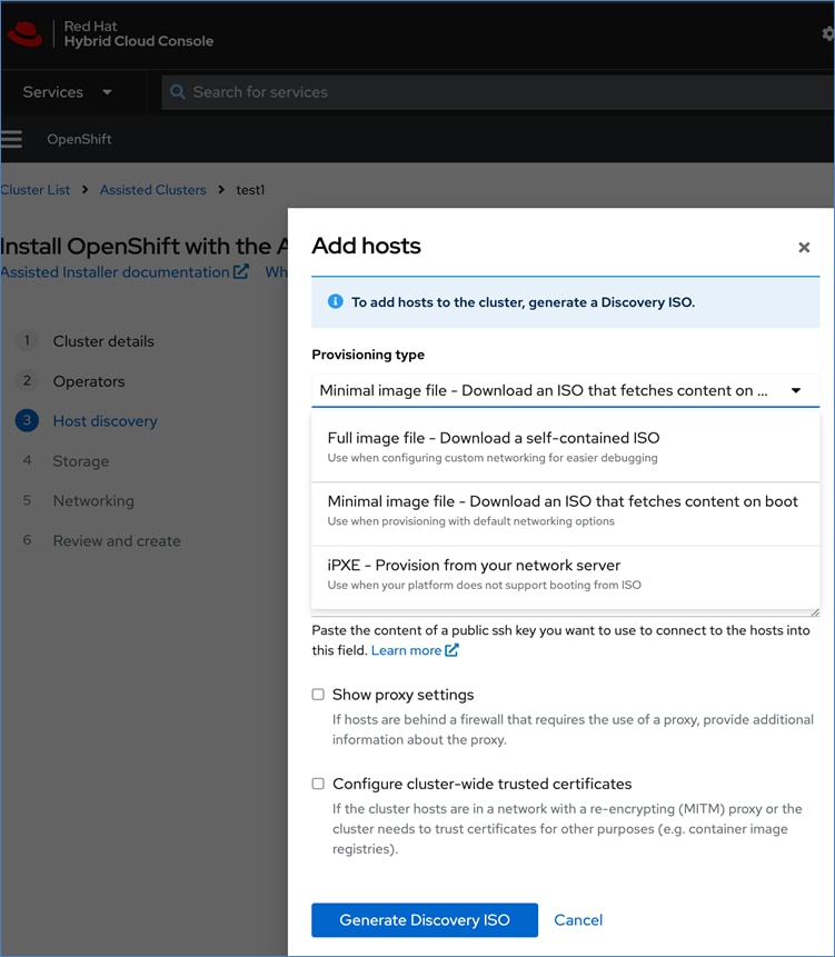
Cisco and Red Hat provides an integration that allows the discovery ISO to be deployed directly on Cisco UCS servers provisioned in Cisco Intersight by clicking on the direct link to Intersight as shown below:
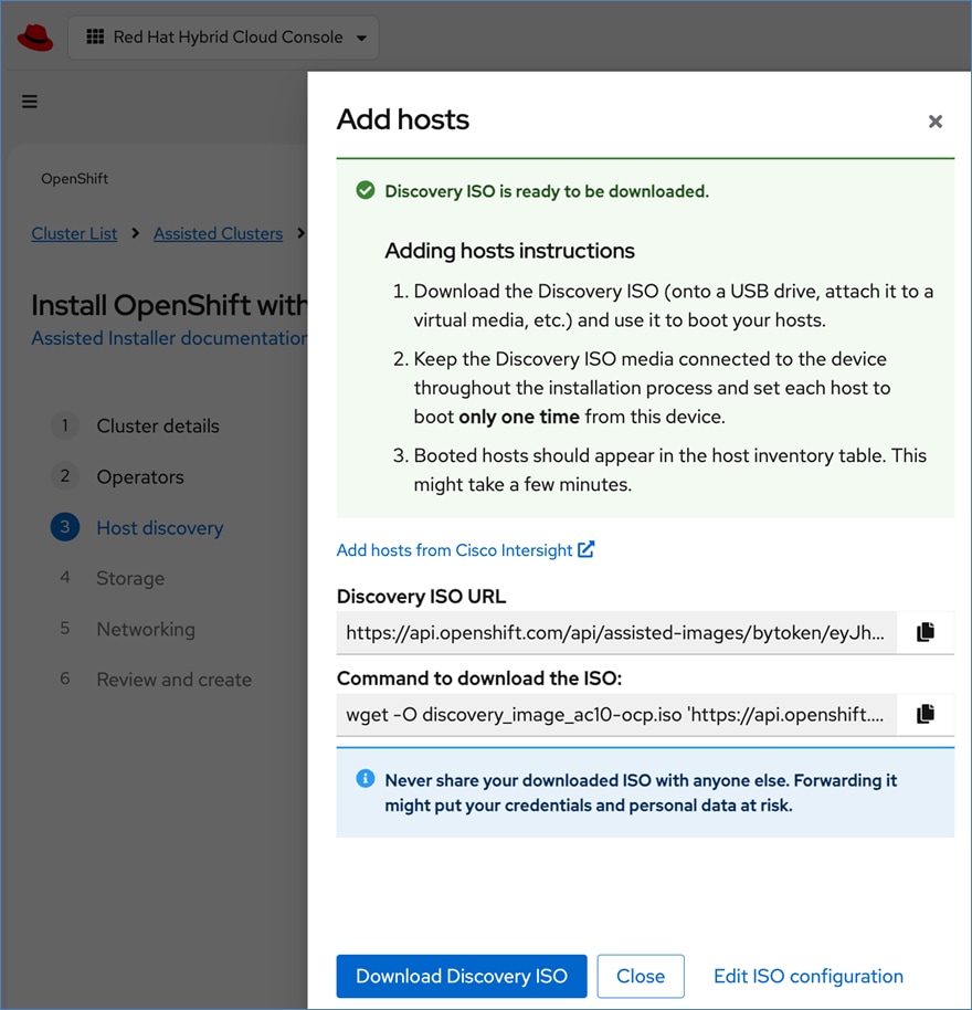
Note: This integration makes bare-metal deployment of an OpenShift cluster on Cisco UCS servers significantly easier.
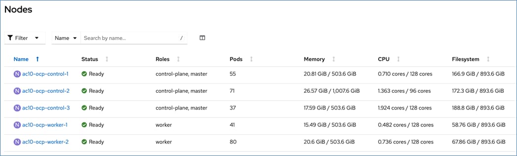
For a high-availability cluster, OpenShift typically requires 3 control nodes and two or more compute (or worker) nodes. The initial cluster used for validation is shown in Figure 17. Additional nodes can be added as needed to scale the cluster.
All network interfaces are provisioned using DHCP – DHCP requests are either routed through the gateway using DHCP relay or directly on the same segment (for storage vNICs) in this design. DNS, DHCP and NTP must all be setup prior to starting the installation.
Post-install, BMC access (for example, IPMI), NTP, etcd backup, storage and other post-install activities will need to be provisioned as needed.
To support AI/ML efforts, the two compute/worker nodes are paired with Cisco UCS X440p nodes in adjacent slots, each equipped with NVIDIA L40S GPUs. These GPUs can be used by workloads running on OpenShift AI or directly on the OpenShift cluster.
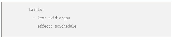
When using GPUs, if not all worker nodes in the cluster are GPU-enabled, it is important to provision taints and tolerations on the nodes and workloads. This ensures that only workloads requiring GPUs are scheduled on the GPU-equipped nodes.
Workloads:

Nodes:
OpenShift Networking Design
OpenShift networking enables communication between various components both internal and external to the cluster.
Control Plane nodes and worker nodes, connect to two networks; OVN-Kubernetes that OpenShift manages and then the physical datacenter network.
For communication outside the cluster, the virtual NICs provisioned on UCS server nodes provide connectivity to the physical data center network.
Table 4. Cisco UCS Server and OpenShift Network Mapping
| UCS vNIC |
Worker Node Interface |
VLAN |
Header D |
Failover |
| IB-MGMT_vNIC |
eno5 |
1201 |
For BMC access and other mgmt. functions |
Fabric Failover on UCS FI |
| CLUSTER-MGMT_vNIC |
eno6 |
1202 |
OpenShift cluster/machine network |
Fabric Failover on UCS FI |
| iSCSI-A_vNIC |
eno7 |
3015 |
For direct iSCSI storage access via Path-A |
Redundant NICs/paths |
| iSCSI-B_vNIC |
eno8 |
3025 |
For direct iSCSI storage access via Path-B |
Redundant NICs/paths |
| NVMe-TCP-A_vNIC |
eno7 |
3035 |
For direct NVMe-TCP storage access via Path-A |
Redundant NICs/paths |
| NVMe-TCP-B_vNIC |
eno8 |
3045 |
For direct NVMe-TCP storage access via Path-B |
Redundant NICs/paths |
| NFS_vNIC |
eno9 |
3055 |
For direct NFS Storage access |
Fabric Failover on UCS FI |
| OBJ_NIC |
eno10 |
1209 |
For S3-compatible object store access |
Fabric Failover on UCS FI |
Note: Cisco UCS FIs do not support LACP based NIC teaming/port-channeling, so it is not an option in this design.
For connectivity within the cluster, OpenShift uses Software-Defined Networking (SDN) to create overlay networks to interconnect pods and services across the cluster. The default networking in OpenShift is Open Virtual Networking – Kubernetes (or OVN-Kubernetes). OVN-Kubernetes is an open-source project that provides networking for Kubernetes clusters with OVN (Open Virtual Networking) and Open vSwitch (Open Virtual Switch) in its core architecture. It is plug-in, specifically designed for Kubernetes, and conforms to Kubernetes Container Network Interface (CNI) specifications.
Figure 18 illustrates the OpenShift networking on control and compute nodes in this solution.

CLUSTER-MGMT network is the cluster or machine network that all control and worker nodes are connected to. Overlay networks are created on this network for pods and services connectivity.
IB-MGMT network is included to provide independent management connectivity to the nodes. This network is used in this solution for management function, for example IPMI access and for loading Red Hat CoreOS to the servers during the install process.
Additional storage network interfaces and VLANs provide connectivity to NetApp storage – either directly or through NetApp Trident (file, block) and S3 compatible object store, also on NetApp storage.
For cluster networking (CLUSTER-MGMT), OVN architecture provides two key components, OVN controller and OVS virtual switch, which are deployed on each node to manage the networking, packet forwarding and policies. OVN configures the OVS on each node to implement the declared network configuration. OVN uses the Geneve (Generic Network Virtualization Encapsulation) protocol to create overlay network between nodes.
The post-install and once DHCP has successfully provisioned the interfaces, each worker node should have a configuration as shown in Figure 19.
By default, Kubernetes (and OpenShift) allocates each pod an internal cluster-wide IP address that it can use for Pod-to-Pod communication using the Pod network. Within a Pod, all containers behave as if they’re on the same logical host and communicate with each other using localhost, using the ports assigned to the containers. For services, OpenShift, as in Kubernetes, exposes services using an internal stable IP address from within the cluster. This internal IP address, known as the ClusterIP, is type of service that allows other pods within the same cluster to communicate with the service without exposing it to the external network.
For communication outside the cluster, OpenShift provides services (node ports, load balancers) and API resources (Ingress, Route) to expose an application or a service outside cluster so that users can securely access the application or service running on the OCP cluster.
OpenShift Operators
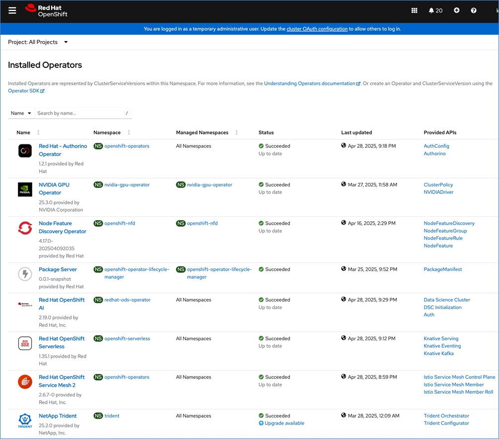
Operators are a powerful tool in Kubernetes. It was designed to extend the capabilities of a Kubernetes cluster without changing the core Kubernetes code. Once a cluster is deployed, Red Hat OpenShift operators can be deployed to enable persistent storage, GPU acceleration and other services. A library of certified and community operators are available on Red Hat’s OperatorHub that is directly accessible from the cluster console. The operators deployed for this solution are shown in Figure 20.
NVIDIA GPU Operator
The NVIDIA GPU Operator uses the operator framework within Kubernetes to automate the management of all NVIDIA software components needed to provision and monitor GPUs. These components include:
● NVIDIA drivers (to enable CUDA)
● Kubernetes device plugin for GPUs
● NVIDIA Container Runtime
● Automatic node labeling
● NVIDIA DCGM exporter
The GPU operator is responsible for enabling GPU acceleration on UCS-X worker nodes with NVIDIA GPUs on X440p GPU nodes. The NVIDIA GPU operator also requires Red Hat’s Node Feature Discovery Operator to detect the GPUs assigned to the worker node.
Red Hat Node Feature Discovery Operator
The Node Feature Discovery Operator (NFD) is responsible for detecting hardware capabilities and labeling the nodes with the hardware-specific information so that OpenShift cluster can use them. For NVIDIA GPUs on Cisco UCS worker nodes, the NFD Operator detects and labels it using the following label:

NetApp Trident Operator
NetApp Trident is an open-source storage provisioner and orchestrator maintained by NetApp. It enables you to create storage volumes for containerized applications managed by Docker and Kubernetes. It has been designed to help you meet your containerized application's persistence demands using industry-standard interfaces, such as the Container Storage Interface (CSI). For the release information, including patch release changes, see https://docs.netapp.com/us-en/trident/trident-rn.html.
Red Hat OpenShift AI Operator
Red Hat OpenShift AI operator deploys OpenShift AI on the OpenShift cluster that enables a fully supported environment for MLOps. The OpenShift AI environment deployed by the operator provides a core environment with built-in tools, libraries, and frameworks that ML engineers and data scientists need to train and deploy models. The GPU resources deployed on the OpenShift cluster are automatically available from the OpenShift AI UI and can be used as needed during various stages of model delivery ( for example, GPUs can be assigned to a Jupyter notebook for use in model experimentation). OpenShift AI includes project workspaces to enable multiple AI/ML efforts in parallel, Jupyter Notebooks with different built-in images to pick from (for example, PyTorch, TensorFlow, CUDA), Data Science Pipelines using OpenShift pipelines, model serving using ModelMesh (and Kserve) with Intel OpenVINO inferencing server. Customers can extend this environment by adding custom images, and other partner and open-source technologies. By using the operator framework, it is also simple to use the lifecycle OpenShift AI.
MLOps using Red Hat OpenShift AI
Red Hat OpenShift includes key capabilities to streamline and scale machine learning operations (MLOps) in a consistent way. By applying DevOps and GitOps principles, organizations automate and simplify the iterative process of integrating ML models into software development processes, production rollout, monitoring, retraining, and redeployment to ensure continued prediction accuracy.
Red Hat OpenShift AI leverages OpenShift’s capabilities in application development and container infrastructure management to enable a robust, scalable, and secure environment for model delivery and MLOps. OpenShift Administrators manage all aspects of the underlying infrastructure, from GPU resources to storage to user access. This eases the operational burden on ML engineers and data scientists, enabling them to focus on model delivery and less time on managing the infrastructure. OpenShift also provides integration with DevOps capabilities (for example, OpenShift Pipelines, OpenShift GitOps, and Red Hat Quay). Also, projects and workbenches deployed in OpenShift AI are projects (or namespaces) in OpenShift, enabling Openshift administrator to monitor and manage the resources in their environment. These operational benefits make it significantly easier for Enterprise teams, enabling them to accelerate their ML efforts .
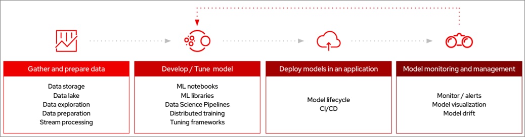
At a high level, a ML lifecycle can be summarized as follow. Red Hat OpenShift AI provides a unified platform for each of the above stages, along with the required AI/ML tools and applications.
● Gather and prepare (or curate) data to make sure the input data is complete, and of high quality
● Develop model, including training, testing, and selection of the model with the highest prediction accuracy
● Integrate models in application development process, and inferencing
● Model monitoring and management, to measure business performance and address potential production data drift
Multiple efforts can run in parallel within OpenShift AI, from incubation projects to production serving of multiple models at scale. Red Hat OpenShift AI platform provides key capabilities to support this and accelerate model delivery as outlined below.
● Seamlessly leverage resources and capabilities from the underlying OpenShift cluster (for example, use OpenShift Identity provider to manage users).
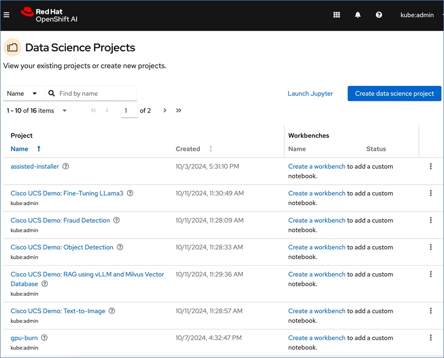
● Support for multiple Data Science Projects to enable parallel AI/ML efforts, including multiple workflows (known as workbenches) within a project.
● Support for multiple work efforts or Workbenches within a given data science project to support parallel work efforts within the same projects. A workbench is an isolated area where you can work with models in your preferred IDE, such as a Jupyter notebook. You can add accelerators and data connections, create pipelines, and add cluster storage in your workbench. The workbenches can be launched with pre-built or custom images with necessary libraries and frameworks.
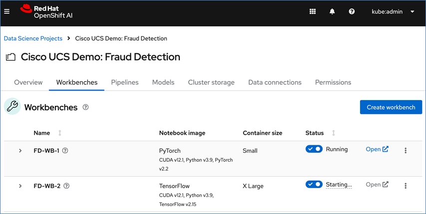
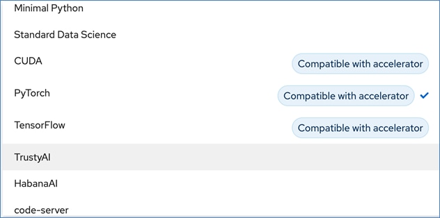
● The pre-built image options available in the release of OpenShift AI used in this design include commonly used images such as: Minimal Python, Standard Data Science, CUDA, PyTorch, TensorFlow, TrustyAI, Habana AI, and Code-server.

● Other notebook options you can select from include:
◦ Container size (Small, Medium, Large, and X Large) based on memory and CPU requirements for project
◦ Number of GPU accelerators (optional)
◦ Persistent Storage – new or existing (provided by NetApp Trident in this solution)
◦ Data Connection to access S3-compatible storage on NetApp ONTAP storage on-prem
● If GPU acceleration is selected, OpenShift AI will detect and make the GPU available for use. The pre-built images that support GPU acceleration will also be updated to indicate that it is available s shown below. Otherwise, CPU resources will be used. Within a given data science project, the parallel efforts on different workbenches can individually select whether to use GPU or CPU resources.
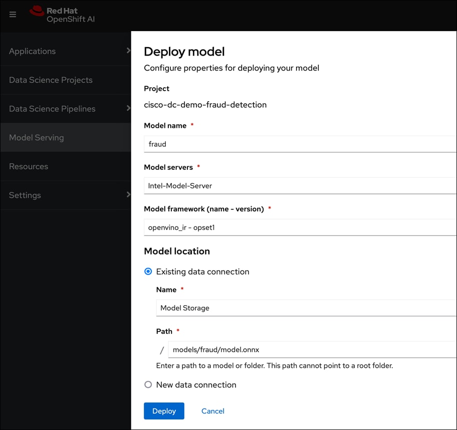
● For model serving using pre-integrated Intel OpenVINO inferencing server or use a custom server such as NVIDIA Triton. For model serving, you can specify the model repository where the model is stored, the format or framework the published model uses (for example, onnx, tensorflow, openvino_ir) as well as the number of GPU accelerators to use.
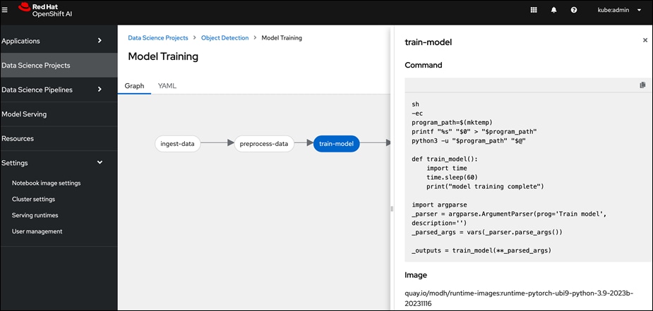
● Simple drag and drop GUI based Pipeline Automation with options to schedule execution runs.
Red Hat OpenShift AI provides flexibility and scalable platform for an Enterprise AI/ML initiatives by providing pre-integrated both pre-integrate and customizable environments without compromising on flexibility, in an easy-to-use interface with automation, Jupyter notebooks, GitHub access, and multiple storage and database options The scalability of the solution will primarily depend on underlying OpenShift infrastructure and environment.
End-to-End Design
The FlexPod AI solution with MLOps is now capable of supporting a wide range of ML model delivery efforts, including both Predictive AI and Generative AI, single-modal and multi-modal, as well as CPU and GPU-based use cases with flexible inferencing engines and runtimes. The solution offers a foundational infrastructure platform to simplify, streamline and expedite an enterprise's AI/ML initiatives. The comprehensive design for the solution is shown in Figure 21.
Once the models are ready, they can be served and monitored through OpenShift AI. Enterprise applications can leverage this environment for everything from experimentation to production, seamlessly integrating their applications with the served models to support a variety of use cases as illustrated in Figure 22.
Solution Deployment
This chapter contains the following:
● Deploy Networking – Cisco Nexus
● Deploy Storage - NetApp ONTAP
● Deploy Kubernetes – OpenShift on Baremetal UCS Servers
● Deploy NetApp Trident Operator
● Deploy GPU Operator - NVIDIA
● Deploy Red Hat OpenShift AI for MLOps
● Visibility and Monitoring – GPU
This chapter provides an high-level overview of the implementation steps for deploying the solution, followed by step-by-step guidance for implementing each step in the overall solution.
The AI/ML infrastructure leverages the latest FlexPod Datacenter CVD for Cisco UCS M7 baremetal servers running Red Hat OpenShift as the foundational design for containerized AI/ML workloads running on Red Hat OpenShift and MLOps for model deployment and maintenance using Red Hat OpenShift AI.
Check Cisco UCS Hardware Compatibility List for NVIDIA GPU support on Cisco UCS running Red Hat OpenShift and upgrade UCS server firmware as needed.
With the FlexPod Datacenter infrastructure in place, an overview of the remaining deployment steps to bring up the AI/ML infrastructure for model serving in production with MLOps are summarized in Table 5.
The detailed procedures for the steps listed in this table will be available on GitHub in the future: https://github.com/ucs-compute-solutions/FlexPod-OpenShift-AI
| Steps |
Deployment Action |
| 01_CVD |
Cisco Nexus Switch Configuration: Configure both Nexus switches for network connectivity. |
| 02_CVD |
NetApp AFF Storage Configuration: Configure NetApp storage for use in OCP Bare Metal and OpenShift AI.
● Setup NFS, iSCSI, NVMe-TCP and S3 related configuration
● Setup ONTAP S3 object store to be used by OpenShift AI for storing pipeline artifacts and model repo
|
| 03_CVD |
Cisco UCS Server Configuration: Provision Cisco UCS-X servers from Cisco Intersight to support AI/ML workloads. This requires deploying servers with PCIe nodes and GPUs. |
| 04_CVD |
Red Hat OpenShift Prerequisites: Setup and/or verify that the following prerequisites for Red Hat OpenShift are in place.
● Deploy an installer machine to remotely manage the OpenShift cluster and to serve as an HTTP server to load openshift images on Cisco UCS servers. Generate public SSH keys on the installer to enable SSH access to OpenShift cluster post-install.
● Valid Red Hat account to access Red Hat Hybrid Cloud Console (HCC) for deploying OpenShift.
● Identify a VLAN, IP subnet and DNS domain for use by Red Hat OpenShift cluster.
● Setup DNS: Add DNS records for API VIP and Ingress Virtual IP (VIP)
● Setup DHCP: Add DHCP pool for OpenShift cluster nodes to use. Configure DHCP options for NTP, Gateway (for routed subnets) and DNS.
● Assisted Installer will check for the following before starting the installation:
◦ Network connectivity ◦ Network bandwidth ◦ Connectivity to the registry ◦ Upstream DNS resolution of the domain name ◦ Time synchronization between cluster nodes ◦ Cluster node hardware ◦ Installation configuration parameters |
| 05_CVD |
Deploy Red Hat OpenShift: Install OpenShift from console.redhat.com using Use Red Hat recommended Assisted Installer to deploy an OpenShift Baremetal cluster for hosting AI/ML workloads. |
| 06_CVD |
Red Hat OpenShift - Post-Deployment Verification:
● Verify access to OpenShift cluster by navigation to cluster console URL
● Setup/Verify NTP setup on all OpenShift cluster virtual machines (control and worker nodes)
● Enable IPMI for each baremetal host from the OpenShift cluster console
● Verify cluster is registered with
console.redhat.com
● From Red Hat OpenShift cluster console, provision machineset to modify CPU, memory as needed.
● Provision taints on the Openshift worker nodes with GPUs to only allow workloads that require a GPU to be scheduled on them.
|
| 07_CVD |
Deploy NVIDIA GPU Operator on Red Hat OpenShift:
● From the Red Hat OpenShift Console, search and deploy Red Hat’s Node Feature Discovery Operator (NFD).
● Verify that the worker nodes with GPUs have identified and labelled the GPU. Label should be:
● From the Red Hat OpenShift cluster console, search and deploy the NVIDIA GPU Operator:
◦ Deploy Cluster Policy instance and ensure that it shows a Status of State: Ready ◦ Use the following command to verify GPU details: oc exec -it <nvidia-driver-daemonset pod name> -- nvidia-smi (option: -q)
● Enable DCGM GPU Monitoring Dashboard in Red Hat OpenShift:
https://docs.nvidia.com/datacenter/cloud-native/openshift/latest/enable-gpu-monitoring-dashboard.html
|
| 08_CVD |
Deploy Persistent Storage on Red Hat OpenShift using NetApp Trident The persistent storage will be used Red Hat OpenShift containers and AI workloads.
● Deploy NetApp Trident as an operator or using Helm charts, backed by iSCSI, NVMe-TCP or NFS datastores on NetApp ONTAP storage
● Create one or more Storage Classes for above
● Create a test Persistent Volume Claim
● Provision of the newly created storage classes as the default storage class
|
| 09_CVD |
Deploy Red Hat OpenShift AI for MLOps This involves the following prerequisites and high-level tasks:
● Provision or use existing identity provider from Red Hat OpenShift.
● Add users and administrator groups in OpenShift to enable for access to OpenShift AI web UI.
● Deploy GPU resources for AI/ML efforts (for efforts that require GPUs)
● Deploy Persistent storage for AI/ML efforts. In this solution, the ML engineer’s work (image, environment) is saved on Trident persistent volumes, backed by NetApp ONTAP storage.
● Deploy S3-compatible object store. In this CVD, it used as model repository and to store pipeline artifacts on NetApp AFF storage
● When using GPUs, if all nodes in the OpenShift cluster are not using GPUs, then taints and tolerations should be provisioned on the nodes to ensure that only workloads requiring GPUs are scheduled on the nodes with GPUs.
● Deploy Red Hat OpenShift AI Operator. The environment is now ready for accelerating and operationalizing enterprise AI/ML efforts at scale.
|
| 10_CVD |
Sanity Tests
● GPU Functional Validation – Sample CUDA Application
● GPU Burn Test:
https://github.com/wilicc/gpu-burn
● Sample PyTorch script executed from Red Hat OpenShift AI
|
Deploy Networking – Cisco Nexus
The procedures detailed in this section will configure the necessary networking on Cisco Nexus 9000 series switches to enable connectivity between the different components in the solution. This section explains the following:
● Initial setup of Cisco Nexus 9000 series Top-of-Rack (ToR) switches.
● Provision Cisco Nexus switches to enable the connectivity that infrastructure and workloads running on the infrastructure need. This includes connectivity between UCS domains and NetApp storage directly connected to the switches, as well as upstream connectivity to other networks, both within the enterprise and externally.
Note: The Nexus switches used in the solution will be referred to as Nexus-A and Nexus-B. The screenshots will show their actual hostnames.
Initial Setup of Cisco Nexus 9000 Series ToR Switches
This section describes the initial setup of a pair of Cisco Nexus 9000 series Top-of-Rack (ToR) switches used in the solution.
Assumptions and Prerequisites
● Assumes a greenfield deployment with new Nexus switches that have not been configured.
● Console access to both Cisco Nexus switches.
● Collect the setup information for your environment – see Table 6.
Setup Information
Table 6 lists the setup parameters and other information necessary for the procedures in this section. The information also includes access information for devices used in the configuration.
Table 6. Cisco Nexus: Initial Setup Parameters and Information
| Variable/Info |
Value |
Additional Values and Information |
| Console Access: Nexus-A |
<collect> |
|
| Console Access: Nexus-B |
<collect> |
|
| Nexus-A/-B: Admin Username |
admin |
Assuming the same values are used for Nexus-A and Nexus-B |
| Nexus-A/-B: Admin Password |
<specify> |
|
| Nexus-A: Hostname |
AC10-N93600CD-GX-A |
|
| Out-of-Band Management IPv4 Address |
10.120.0.5 |
Options: IPv4 or IPv6 |
| Out-of-Band Management Netmask |
255.255.255.0 |
|
| Out-of-Band Management Gateway |
10.120.0.254 |
|
| Nexus-B: Hostname |
AC10-N93600CD-GX-A |
|
| Out-of-Band Management IPv4 Address |
10.120.0.6 |
Options: IPv4 or IPv6 |
| Out-of-Band Management Netmask |
255.255.255.0 |
|
| Out-of-Band Management Gateway |
10.120.0.254 |
|
Deployment Steps
Use the setup information in Table 6 for the procedures detailed in this section.
Procedure 1. Initial setup of the Nexus-A switch
Step 1. Connect to the console port of the first Nexus switch (Nexus-A) .
Step 2. Power on the switch.
Note: On bootup, Nexus should automatically start and attempt to enter Power on Auto Provisioning (PoAP).
Step 3. Click Yes to abort PoAP and continue with normal setup.
Step 4. Specify an admin password to access the switch.
Step 5. Click Yes to enter the basic configuration dialog.
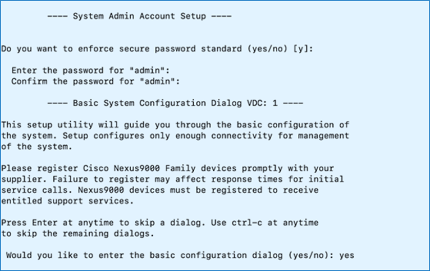
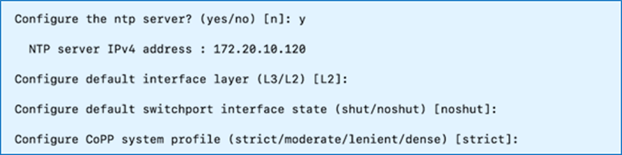
Step 6. Specify a switch name, Mgmt0 IPv4 address, netmask, and default gateway. You can choose the default options for everything else or modify it as you see fit for your environment.
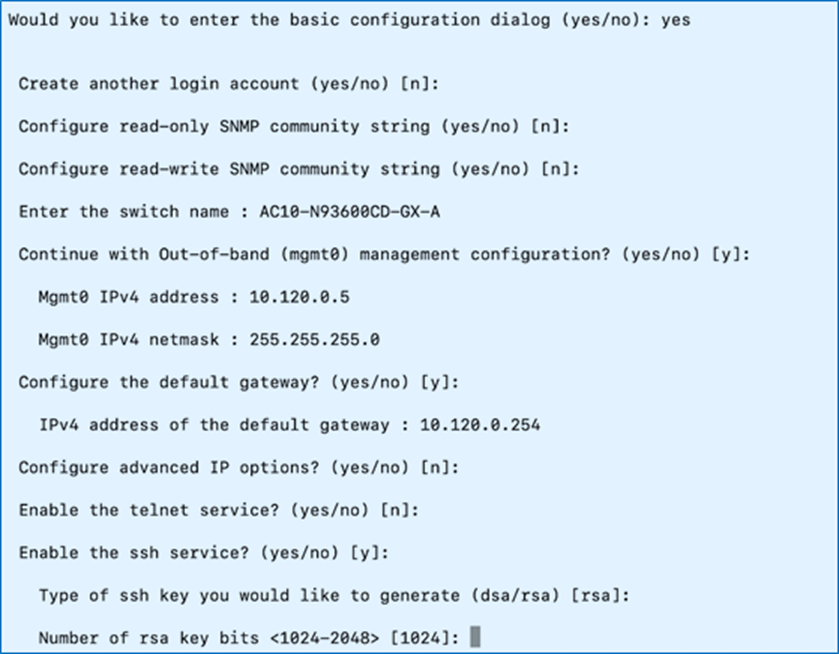
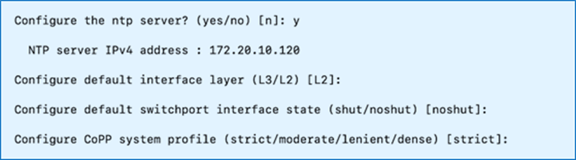
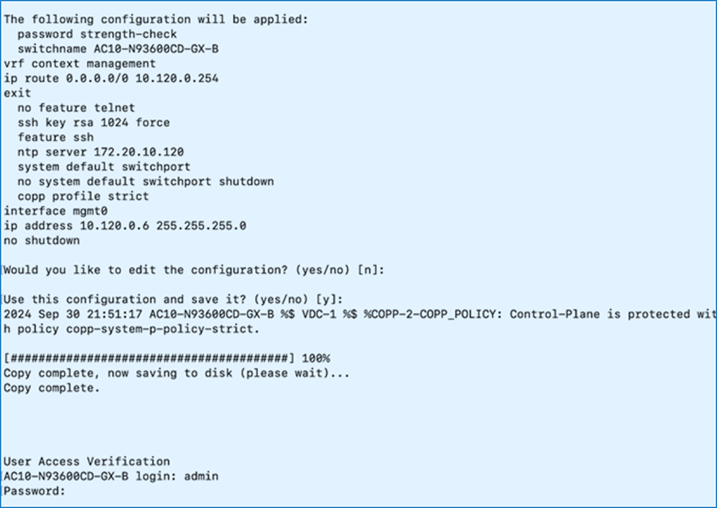
Step 7. Review and Save to use the specified configuration.
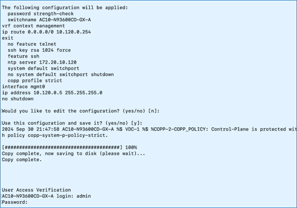
Procedure 2. Initial setup of the Nexus-B switch
Step 1. Repeat the configuration steps in Procedure 1 to set up the Nexus-B switch.
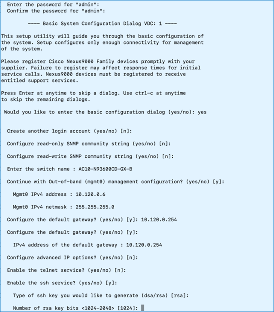
Step 2. Review the configuration. Confirm to use the configuration and Save it.
Provision Cisco Nexus Switches to enable workload and infrastructure connectivity
The procedures detailed in this section configure the Nexus 9000 series switches in the solution to provide the necessary infrastructure and workload connectivity.
Assumptions and Prerequisites
● The initial setup of the Nexus switches is complete.
● Collect the setup information for your environment – see Table 7.
Setup Information
The setup parameters and other information necessary to configure the components in this section, including access information are listed in Table 7.
Table 7. Cisco Nexus: Setup Parameters and Information
| Variable/Info |
Variable Name |
Value |
Additional Values and Information |
| Nexus Global Configuration – General |
|||
| Features |
|
nxapi udld interface-vlan lacp vpc lldp scp-server sftp server |
|
| DNS Server IP |
|
172.20.4.53 172.20.4.54 |
Could be multiple |
| DNS Domain Name |
|
fpb.local |
|
| NTP Server IP |
|
172.20.10.120 |
|
| Clock Time Zone |
|
EST -5 |
|
| Clock Summertime |
|
EDT |
|
| In-Band Management |
|||
| In-Band Management VLAN |
FPB-IB-MGMT_VLAN |
1201 |
|
| VLANs – to Cisco UCS Compute Infrastructure |
|||
| Native VLAN |
FPB-NATIVE_VLAN |
2 |
|
| OpenShift Cluster Management VLAN |
FPB-CLUSTER-MGMT_VLAN |
1202 |
|
| Storage Access – Object Store |
FPB-S3-OBJ_VLAN |
1209 |
|
| Storage Access – iSCSI-A |
FPB-iSCSI-A_VLAN |
3015 |
|
| Storage Access – iSCSI-B |
FPB-iSCSI-B_VLAN |
3025 |
|
| Storage Access – NVMe-TCP-A |
FPB-NVMe-TCP-A_VLAN |
3035 |
|
| Storage Access – NVMe-TCP-B |
FPB-NVMe-TCP-B_VLAN |
3045 |
|
| Storage Access – NFS VLAN |
FPB-NFS_VLAN |
3055 |
|
| Gateway IP |
|||
| Out-of-Band Management Gateway IP |
FPB-OOB-MGMT-GW_IP |
10.120.0.254/24 |
External to Nexus-A, -B |
| In-Band Management Gateway IP |
FPB-IB-MGMT-GW_IP |
10.120.1.254/24 |
External to Nexus-A, -B |
| OpenShift Cluster Management Gateway IP |
FPB-CLUSTER-MGMT-GW _IP |
10.120.2.254/24 |
External to Nexus-A, -B |
| Storage Access – Object Store Gateway IP |
FPB-S3-OBJ-GW_IP |
10.120.9.254/24 |
External to Nexus-A, -B |
| Subnets |
|||
| Storage Access – iSCSI-A Subnet |
|
192.168.10.0/24 |
|
| Storage Access – iSCSI-B Subnet |
|
192.168.20.0/24 |
|
| Storage Access – NVMe-TCP-A Subnet |
|
192.168.30.0/24 |
|
| Storage Access – NVMe-TCP-B Subnet |
|
192.168.40.0/24 |
|
| Storage Access – NFS Subnet |
|
192.168.50.0/24 |
|
| Nexus-A vPC Global Configuration |
To UCS Fabric Interconnects |
||
| vPC Domain ID |
FPB-VPC-DOMAIN_ID |
20 |
|
| vPC Peer Keepalive - Destination |
FPB-OOB-MGMT-B_IP |
OOB Mgmt. IP of Nexus-B |
(for example, 10.120.0.6) |
| vPC Peer Keepalive - Source |
FPB-OOB-MGMT-A_IP |
OOB Mgmt. IP of Nexus-A |
(for example, 10.120.0.5) |
| Nexus-B vPC Global Configuration |
To UCS Fabric Interconnects |
||
| vPC Domain ID |
FPB-VPC-DOMAIN_ID |
20 |
|
| vPC Peer Keepalive - Destination |
FPB-OOB-MGMT-A_IP |
OOB Mgmt. IP of Nexus-A |
(for example, 10.120.0.5) |
| vPC Peer Keepalive - Source |
FPB-OOB-MGMT-B_IP |
OOB Mgmt. IP of Nexus-B |
(for example, 10.120.0.6) |
| Nexus-A Peer-Link Configuration |
|||
| vPC Peer Link – Port Channel ID |
|
100 |
To Nexus-B |
| vPC Peer Link – Interfaces |
|
e1/27-28 |
|
| Nexus-A vPC Configuration to Upstream Datacenter Network |
|||
| vPC ID |
|
120 |
To upstream switch-1,-2 |
| Port Channel ID |
|
120 |
|
| Local Interface |
|
e1/25 |
To upstream switch-1 |
| Remote Interface |
|
e1/49 |
|
| Local Interface |
|
e1/26 |
To upstream switch-2 |
| Remote Interface |
|
e1/49 |
|
| Nexus-A vPC Configuration to UCS Fabric Interconnects |
|||
| vPC ID |
|
11 |
To Fabric Interconnect A |
| Port Channel ID |
|
11 |
|
| Local Interface |
|
e1/5 |
|
| Remote Interface |
|
e1/32 |
|
| vPC ID |
|
12 |
To Fabric Interconnect B |
| Port Channel ID |
|
12 |
|
| Local Interface |
|
e1/6 |
|
| Remote Interface |
|
e1/32 |
|
| Nexus-A Interface Configuration to NetApp Controllers: e3a_ifgrp, e3b_ifgrp |
For iSCSI, NVMe-TCP, NFS |
||
| vPC ID |
|
13 |
To NetApp:e3a_ifgrp |
| Port Channel ID |
|
13 |
|
| Local Interface to e3a_ifgrp |
|
e1/3 |
|
| Remote Interface |
|
e3a |
|
| vPC ID |
|
14 |
To NetApp:e3b_ifgrp |
| Port Channel ID |
|
14 |
|
| Local Interface to e3b_ifgrp |
|
e1/4 |
|
| Remote Interface |
|
e3b |
|
| Nexus-B Peer-Link Configuration |
|||
| vPC Peer Link – Port Channel ID |
|
100 |
To Nexus-A |
| vPC Peer Link – Interfaces |
|
e1/27-28 |
|
| Nexus-B vPC Configuration to Upstream Datacenter Network |
|||
| vPC ID |
|
120 |
To upstream switch-1,-2 |
| Port Channel ID |
|
120 |
|
| Local Interface |
|
e1/25 |
To upstream switch-1 |
| Remote Interface |
|
e1/50 |
|
| Local Interface |
|
e1/26 |
To upstream switch-2 |
| Remote Interface |
|
e1/50 |
|
| Nexus-B vPC Configuration to UCS Fabric Interconnects |
|||
| vPC ID |
|
11 |
To Fabric Interconnect A |
| Port Channel ID |
|
11 |
|
| Local Interface |
|
e1/5 |
|
| Remote Interface |
|
e1/32 |
|
| vPC ID |
|
12 |
To Fabric Interconnect B |
| Port Channel ID |
|
12 |
|
| Local Interface |
|
e1/6 |
|
| Remote Interface |
|
e1/32 |
|
| Nexus-B Interface Configuration to NetApp Controllers: e3a_ifgrp, e3b_ifgrp |
For iSCSI, NVMe-TCP, NFS,S3 |
||
| vPC ID |
|
13 |
To NetApp:e3a_ifgrp |
| Port Channel ID |
|
13 |
|
| Local Interface to e3a_ifgrp |
|
e1/3 |
|
| Remote Interface |
|
e3a |
|
| vPC ID |
|
14 |
To NetApp:e3b_ifgrp |
| Port Channel ID |
|
14 |
|
| Local Interface to e3b_ifgrp |
|
e1/4 |
|
| Remote Interface |
|
e3b |
|
Deployment Steps: Nexus-A Switch
Use the setup information listed in Table 7 to configure and deploy the Nexus-A switch.
Procedure 1. Configure and deploy the Nexus-A switch
Step 1. Log in and enable global features on Nexus-A switch.
Step 2. SSH into Nexus-A switch and log in as admin.
Step 3. Enter the configuration mode on Nexus-A switch:
AC10-N93600CD-GX-A# conf t
Enter configuration commands, one per line. End with CNTL/Z.
AC10-N93600CD-GX-A(config)#
Step 4. Run the following commands to enable the following features. Some (for example, sftp-server) are optional:
feature nxapi
feature scp-server
feature sftp-server
feature udld
feature interface-vlan
feature lacp
feature vpc
feature lldp
Procedure 2. Configure DNS, NTP, Clock, and other global configurations on the Nexus-A switch
Step 1. From the configuration mode on the Nexus-A switch, run the following commands:
clock timezone EST -5 0
clock summer-time EDT 2 Sunday March 02:00 1 Sunday November 02:00 60
ip domain-lookup
ip domain-name fpb.local
ip name-server 172.20.4.53 172.20.4.54
ntp server 172.20.10.120 use-vrf management
ntp master 3
spanning-tree port type edge bpduguard default
spanning-tree port type edge bpdufilter default
spanning-tree port type network default
Procedure 3. Configure the FlexPod VLANs on the Nexus-A switch
Step 1. From the configuration mode on the Nexus-A switch, create the in-band management VLAN. Configure the interface VLAN and Gateway IP if you’re using this switch as default GW:
Note: In this design, a pair of upstream Nexus switches (outside the scope of this CVD) is used and therefore not configured on these switches.
vlan 1201
name FPB-IB-MGMT_VLAN_1201
Step 2. From the configuration mode on Nexus-A, provision all remaining FlexPod VLANs. This typically includes the native VLAN, OpenShift Cluster management VLAN, and storage VLANs:
vlan 2
name FPB-NATIVE_VLAN_2
vlan 1202
name FPB-CLUSTER-MGMT_VLAN_1202
vlan 1209
name FPB-S3-OBJ_VLAN
vlan 3015
name FPB-iSCSI-A_VLAN_3015
vlan 3025
name FPB-iSCSI-B_VLAN_3025
vlan 3035
name FPB-NVMe-TCP-A_VLAN
vlan 3045
name FPB-NVMe-TCP-B_VLAN
vlan 3055
name FPB-NFS_VLAN
Procedure 4. Configure the virtual Port Channel (vPC) domain and peer-links on the Nexus-A switch
Step 1. Configure vPC domain and peer keepalives:
vpc domain 20
peer-switch
role priority 10
peer-keepalive destination 10.120.0.6 source 10.120.0.5
delay restore 150
peer-gateway
auto-recovery
ip arp synchronize
Step 2. Configure vPC peer-links:
interface port-channel100
description vPC Peer Link to Nexus Peer switch
switchport mode trunk
switchport trunk native vlan 2
switchport trunk allowed vlan 1201-1209,3015,3025,3035,3045,3055
spanning-tree port type network
vpc peer-link
interface Ethernet1/27
description AC10-N93600CD-GX-B:Eth1/27
switchport mode trunk
switchport trunk native vlan 2
switchport trunk allowed vlan 1201-1209,3015,3025,3035,3045,3055
channel-group 100 mode active
interface Ethernet1/28
description AC10-N93600CD-GX-B:Eth1/28
switchport mode trunk
switchport trunk native vlan 2
switchport trunk allowed vlan 1201-1209,3015,3025,3035,3045,3055
channel-group 100 mode active
Note: vPC peer links are enabled to use Jumbo MTU by default. Attempting to change the MTU manually on a peer-link interface will result in the following error: ERROR: Cannot configure port MTU on vPC Peer-link.
Procedure 5. Configure the upstream connectivity from Nexus-A switch to the enterprise data center network
Step 1. Configure the VPCs from the Nexus-A switches to upstream switches in the enterprise data center network for connectivity to other parts of the enterprise and external networks:
Note: The design of the upstream data center fabric is outside the scope of this CVD. The upstream network could be a traditional VPC based design or a fabric-based design, such as Cisco ACI or VXLAN EVPN fabric.
interface port-channel120
description vPC to Upstream Network (AC05-93180YC-Core-1 & Core-2)
switchport mode trunk
switchport trunk native vlan 2
switchport trunk allowed vlan 1201-1209,3015,3025,3035,3045,3055
spanning-tree port type normal
mtu 9216
vpc 120
interface Ethernet1/25
description vPC to AC05-93180YC-Core-1:p1/49)
switchport mode trunk
switchport trunk native vlan 2
switchport trunk allowed vlan 1201-1209,3015,3025,3035,3045,3055
mtu 9216
channel-group 120 mode active
interface Ethernet1/26
description vPC to AC05-93180YC-Core-2:p1/49)
switchport mode trunk
switchport trunk native vlan 2
switchport trunk allowed vlan 1201-1209,3015,3025,3035,3045,3055
mtu 9216
channel-group 120 mode active
Procedure 6. Configure the vPC connectivity from Nexus-A to Cisco UCS compute infrastructure
Step 1. Configure the first vPC to Cisco UCS compute infrastructure (Fabric Interconnect A). Use (show cdp | lldp neighbors) to verify interface and neighbor connectivity as needed:
interface port-channel11
description AC10-6536-FI-A
switchport mode trunk
switchport trunk native vlan 2
switchport trunk allowed vlan 1201-1209,3015,3025,3035,3045,3055
spanning-tree port type edge trunk
mtu 9216
vpc 11
interface Ethernet1/5
description AC10-UCS-6536-FI-A:Eth1/31
switchport mode trunk
switchport trunk native vlan 2
switchport trunk allowed vlan 1201-1209,3015,3025,3035,3045,3055
spanning-tree port type edge trunk
mtu 9216
channel-group 11 mode active
Note: You may see the following if you attempt to enable udld on a fiber port. This message is expected. UDLD is supported on twinnax but not on fiber ports: The command is not applicable for fiber ports. UDLD is rejecting a config that is valid only for the copper port on Ethernet1/97.
Step 2. Configure the second vPC to Cisco UCS compute infrastructure (Fabric Interconnect B). Use (show cdp | lldp neighbors) to verify interface and neighbor connectivity as needed. See the Note in Step 1 regarding udld.
interface port-channel12
description AC10-6536-FI-B
switchport mode trunk
switchport trunk native vlan 2
switchport trunk allowed vlan 1201-1209,3015,3025,3035,3045,3055
spanning-tree port type edge trunk
mtu 9216
vpc 12
interface Ethernet1/6
description AC10-UCS-6536-FI-B:Eth1/31
switchport mode trunk
switchport trunk native vlan 2
switchport trunk allowed vlan 1201-1209,3015,3025,3035,3045,3055
spanning-tree port type edge trunk
mtu 9216
channel-group 12 mode active
Procedure 7. Verify the vPC is up and operational
Step 1. Run the following command to verify the vPC is operational:
show vpc
Note: Other useful commands to verify the Nexus switch configurations are:
show run spanning-tree all
show run vpc all
show port-channel summary
show udld neighbors
show interface status
Procedure 8. Configure the interfaces from Nexus-A to NetApp Storage
Step 1. Configure the first interface to NetApp Storage:
interface port-channel13
description vPC to AA02-NetApp-C800:e3a_ifgrp
switchport mode trunk
switchport trunk allowed vlan 1201,1209,3015,3025,3035,3045,3055
spanning-tree port type edge trunk
mtu 9216
vpc 13
interface Ethernet1/3
description vPC to AA02-NetApp-C800:e3a
switchport mode trunk
switchport trunk allowed vlan 1201,1209,3015,3025,3035,3045,3055
mtu 9216
channel-group 13 mode active
Step 2. Configure the second interface to NetApp Storage:
interface port-channel14
description vPC to AA02-NetApp-C800:e3b_ifgrp
switchport mode trunk
switchport trunk allowed vlan 1201,1209,3015,3025,3035,3045,3055
spanning-tree port type edge trunk
mtu 9216
vpc 14
interface Ethernet1/4
description vPC to AA02-NetApp-C800:e3b
switchport mode trunk
switchport trunk allowed vlan 1201,1209,3015,3025,3035,3045,3055
mtu 9216
channel-group 14 mode active
Step 3. Run the following to save the configuration:
copy run start
Deployment Steps: Nexus-B Switch
Use the setup information found here to configure and deploy the Nexus-B switch.
Procedure 1. Log in and enable global features on the Nexus-B switch
Step 1. SSH into Nexus-B switch and log in as admin.
Step 2. Enter configuration mode on Nexus-B switch.
Step 3. Enter configuration mode on Nexus-A switch.
AC10-N93600CD-GX-B# conf t
Enter configuration commands, one per line. End with CNTL/Z.
AC10-N93600CD-GX-B(config)#
Step 4. Run the following commands to enable the following features. Some (for example, sftp-server) are optional:
feature nxapi
feature scp-server
feature sftp-server
feature udld
feature interface-vlan
feature lacp
feature vpc
feature lldp
Procedure 2. Configure the DNS, NTP, Clock, and other global configurations on the Nexus-B switch
Step 1. From the configuration mode on the Nexus-B switch, run the following commands:
clock timezone EST -5 0
clock summer-time EDT 2 Sunday March 02:00 1 Sunday November 02:00 60
ip domain-lookup
ip domain-name fpb.local
ip name-server 172.20.4.53 172.20.4.54
ntp server 172.20.10.120 use-vrf management
ntp master 3
spanning-tree port type edge bpduguard default
spanning-tree port type edge bpdufilter default
spanning-tree port type network default
Procedure 3. Configure FlexPod VLANs on the Nexus-B switch
Step 1. From the configuration mode on the Nexus-B switch, create the in-band management VLAN. Configure the interface VLAN and Gateway IP if you’re using this switch as the default GW:
Note: In this design, a pair of upstream Nexus switches (outside the scope of this CVD) are used and therefore not configured on these switches.
vlan 1201
name FPB-IB-MGMT_VLAN_1201
Step 2. From the configuration mode on the Nexus-A switch, provision all remaining FlexPod VLANs. This includes the native VLAN, OpenShift Cluster management VLAN, and storage VLANs:
vlan 2
name FPB-NATIVE_VLAN_2
vlan 1202
name FPB-CLUSTER-MGMT_VLAN_1202
vlan 1209
name FPB-S3-OBJ_VLAN
vlan 3015
name FPB-iSCSI-A_VLAN_3015
vlan 3025
name FPB-iSCSI-B_VLAN_3025
vlan 3035
name FPB-NVMe-TCP-A_VLAN
vlan 3045
name FPB-NVMe-TCP-B_VLAN
vlan 3055
name FPB-NFS_VLAN
Procedure 4. Configure the virtual Port Channel (vPC) domain and peer-links on the Nexus-B switch
Step 1. Configure the vPC domain and peer keepalives:
vpc domain 20
peer-switch
role priority 10
peer-keepalive destination 10.120.0.5 source 10.120.0.6
delay restore 150
peer-gateway
auto-recovery
ip arp synchronize
Step 2. Configure the vPC peer-links:
interface port-channel100
description vPC Peer Link to Nexus Peer switch
switchport mode trunk
switchport trunk native vlan 2
switchport trunk allowed vlan 1201-1209,3015,3025,3035,3045,3055
spanning-tree port type network
vpc peer-link
interface Ethernet1/27
description AC10-N93600CD-GX-B:Eth1/27
switchport mode trunk
switchport trunk native vlan 2
switchport trunk allowed vlan 1201-1209,3015,3025,3035,3045,3055
channel-group 100 mode active
interface Ethernet1/28
description AC10-N93600CD-GX-B:Eth1/28
switchport mode trunk
switchport trunk native vlan 2
switchport trunk allowed vlan 1201-1209,3015,3025,3035,3045,3055
channel-group 100 mode active
Note: The vPC peer links are enabled to use Jumbo MTU by default. Attempting to change the MTU manually on a peer-link interface will result in the following error: ERROR: Cannot configure port MTU on vPC Peer-link.
Procedure 5. Configure the upstream connectivity from the Nexus-B switch to the enterprise data center network
Step 1. Configure the VPCs from the Nexus-A switches to upstream switches in the enterprise data center network for connectivity to the other parts of the enterprise and external networks.
Note: The design of the upstream data center fabric is outside the scope of this CVD. The upstream network could be a traditional VPC-based or a fabric-based design, such as Cisco ACI fabric or VXLAN EVPN fabric.
interface port-channel120
description vPC to Upstream Network (AC05-93180YC-Core-1 & Core-2)
switchport mode trunk
switchport trunk native vlan 2
switchport trunk allowed vlan 1201-1209,3015,3025,3035,3045,3055
spanning-tree port type normal
mtu 9216
vpc 120
interface Ethernet1/25
description vPC to AC05-93180YC-Core-1:p1/50)
switchport mode trunk
switchport trunk native vlan 2
switchport trunk allowed vlan 1201-1209,3015,3025,3035,3045,3055
mtu 9216
channel-group 120 mode active
interface Ethernet1/26
description vPC to AC05-93180YC-Core-2:p1/50)
switchport mode trunk
switchport trunk native vlan 2
switchport trunk allowed vlan 1201-1209,3015,3025,3035,3045,3055
mtu 9216
channel-group 120 mode active
Procedure 6. Configure the vPC connectivity from the Nexus-B switch to the Cisco UCS compute infrastructure
Step 1. Configure the first vPC to Cisco UCS compute infrastructure (Fabric Interconnect A). Use (show cdp | lldp neighbors) to verify interface and neighbor connectivity as needed:
interface port-channel11
description AC10-6536-FI-B
switchport mode trunk
switchport trunk native vlan 2
switchport trunk allowed vlan 1201-1209,3015,3025,3035,3045,3055
spanning-tree port type edge trunk
mtu 9216
vpc 11
interface Ethernet1/5
description AC10-UCS-6536-FI-B:Eth1/31
switchport mode trunk
switchport trunk native vlan 2
switchport trunk allowed vlan 1201-1209,3015,3025,3035,3045,3055
spanning-tree port type edge trunk
mtu 9216
channel-group 11 mode active
Note: You may see the following message if you attempt to enable udld on a fiber port. This message is expected. UDLD is supported on twinnax but not on fiber ports: The command is not applicable for fiber ports. UDLD is rejecting a config that is valid only for the copper port on Ethernet1/97.
Step 2. Configure the second vPC to Cisco UCS compute infrastructure (Fabric Interconnect B). Use (show cdp | lldp neighbors) to verify the interface and neighbor connectivity as needed. See the Note in Step 1 regarding udld.
interface port-channel12
description AC10-6536-FI-B
switchport mode trunk
switchport trunk native vlan 2
switchport trunk allowed vlan 1201-1209,3015,3025,3035,3045,3055
spanning-tree port type edge trunk
mtu 9216
vpc 12
interface Ethernet1/6
description AC10-UCS-6536-FI-B:Eth1/31
switchport mode trunk
switchport trunk native vlan 2
switchport trunk allowed vlan 1201-1209,3015,3025,3035,3045,3055
spanning-tree port type edge trunk
mtu 9216
channel-group 12 mode active
Procedure 7. Verify the vPC is up and operational
Step 1. Run the following command to very the vPC is operational:
show vpc
Note: Other useful commands to verify the Nexus switch configurations are:
show run spanning-tree all
show run vpc all
show port-channel summary
show udld neighbors
show interface status
Procedure 8. Configure interfaces from Nexus-B to NetApp Storage
Step 1. Configure the first interface to NetApp Storage:
interface port-channel13
description vPC to AA02-NetApp-C800:e3a_ifgrp
switchport mode trunk
switchport trunk allowed vlan 1201,1209,3015,3025,3035,3045,3055
spanning-tree port type edge trunk
mtu 9216
vpc 13
interface Ethernet1/3
description vPC to AA02-NetApp-C800:e3a
switchport mode trunk
switchport trunk allowed vlan 1201,1209,3015,3025,3035,3045,3055
mtu 9216
channel-group 13 mode active
Step 2. Configure the second interface to NetApp Storage:
interface port-channel14
description vPC to AA02-NetApp-C800:e3b_ifgrp
switchport mode trunks
switchport trunk allowed vlan 1201,1209,3015,3025,3035,3045,3055
spanning-tree port type edge trunk
mtu 9216
vpc 14
interface Ethernet1/4
description vPC to AA02-NetApp-C800:e3b
switchport mode trunk
switchport trunk allowed vlan 1201,1209,3015,3025,3035,3045,3055
mtu 9216
channel-group 14 mode active
Step 3. Run the following to save the configuration:
copy run start
The procedures detailed in this section configure the NetApp ONTAP Storage for the OpenShift cluster.
Assumptions and Prerequisites
● Assumes that the base storage setup is completed and the ONTAP license has been added to the cluster. To do the base storage setup, follow the steps in section NetApp ONTAP Storage Configuration of the FlexPod Datacenter Base Manual Configuration with Cisco IMM and NetApp ONTAP Deployment Guide.
● Access to NetApp storage.
● Collect the setup information for your environment – see Table 8.
Table 8. NetApp Storage: Setup parameters and information
| Variable/Info |
Variable name |
Value |
Additional Values and Information |
| ifgroup node-01 |
|
a0b |
Multimode LACP |
| ifgroup node-02 |
|
a0b |
Multimode LACP |
| data-interface-node-01 |
|
e3a,e3b |
Towards Nexus Switch |
| data-Interface-node-02 |
|
e3a,e3b |
Towards Nexus Switch |
| ipspace |
|
AC10-OCP |
For OCP cluster |
| nfs-vlan |
|
a0b-3055 |
|
| iscsi-a-vlan |
|
a0b-3015 |
|
| iscsi-b-vlan |
|
a0b-3025 |
|
| nvme-tcp-a-vlan |
|
a0b-3035 |
|
| nvme-tcp-b-vlan |
|
a0b-3045 |
|
| s3-vlan |
|
a0b-1209 |
|
| nfs-lif-01-ip |
nfs-lif-01 |
192.168.55.51 |
IPv4 |
| nfs-lif-02-ip |
nfs-lif-02 |
192.168.55.52 |
IPv4 |
| iscsi-lif-01-ip |
iscsi-lif-01a |
192.168.15.51 |
IPv4 |
| iscsi-lif-02-ip |
iscsi-lif-01b |
192.168.25.51 |
IPv4 |
| iscsi-lif-03-ip |
iscsi-lif-02a |
192.168.15.52 |
IPv4 |
| iscsi-lif-04-ip |
iscsi-lif-02b |
192.168.25.52 |
IPv4 |
| nvme-lif-01-ip |
nvme-tcp-lif-01a |
192.168.35.51 |
IPv4 |
| nvme-lif-02-IP |
nvme-tcp-lif-01b |
192.168.45.51 |
IPv4 |
| nvme-lif-03-IP |
nvme-tcp-lif-02a |
192.168.35.52 |
IPv4 |
| nvme-lif-04-IP |
nvme-tcp-lif-02b |
192.168.45.52 |
IPv4 |
| s3-lif-01-IP |
s3-lif-01 |
10.102.9.51 |
IPv4 |
| s3-lif-02-IP |
s3-lif-02 |
10.102.9.52 |
IPv4 |
| svm-mgmt-lif |
svm-mgmt |
10.120.1.50 |
IPv4 |
| s3-server-name |
|
AC10-OCP-S3 |
Object store server name |
Note: 100GbE network ports used for data services in this solution are e3a and e3b.
Deployment Steps
Procedure 1. Create interface groups and set MTU
Step 1. Open an SSH connection using the cluster IP and log in as admin user.
Step 2. To create LACP interface groups for the 100GbE data interfaces, run the following commands:
network port ifgrp create -node <st-node01> -ifgrp a0b -distr-func port -mode multimode_lacp
network port ifgrp add-port -node <st-node01> -ifgrp a0b -port e3a
network port ifgrp add-port -node <st-node01> -ifgrp a0b -port e3b
network port ifgrp create -node <st-node02> -ifgrp a0b -distr-func port -mode multimode_lacp
network port ifgrp add-port -node <st-node02> -ifgrp a0b -port e3a
network port ifgrp add-port -node <st-node02> -ifgrp a0b -port e3b
Step 3. To change the MTU size on the interface-group ports, run the following commands:
network port modify –node <st-node01> -port a0b –mtu 9000
network port modify –node <st-node02> -port a0b –mtu 9000
Procedure 2. Configure ONTAP Storage for the OpenShift Cluster
Step 1. Create an IPspace for the OpenShift tenant:
network ipspace create -ipspace AC10-OCP
Step 2. Create the AC10-OCP-MGMT, AC10-OCP-NFS, AC10-OCP-iSCSI, AC10-OCP-NVMe-TCP and AC10-OCP-S3 broadcast domains with the recommended maximum transmission unit (MTU):
network port broadcast-domain create -broadcast-domain AC10-OCP-MGMT -mtu 1500 -ipspace AC10-OCP
network port broadcast-domain create -broadcast-domain AC10-OCP-NFS -mtu 9000 -ipspace AC10-OCP
network port broadcast-domain create -broadcast-domain AC10-OCP-iSCSI-A -mtu 9000 -ipspace AC10-OCP
network port broadcast-domain create -broadcast-domain AC10-OCP-iSCSI-B -mtu 9000 -ipspace AC10-OCP
network port broadcast-domain create -broadcast-domain AC10-OCP-NVMe-TCP-A -mtu 9000 -ipspace AC10-OCP
network port broadcast-domain create -broadcast-domain AC10-OCP-NVMe-TCP-B -mtu 9000 -ipspace AC10-OCP
network port broadcast-domain create -broadcast-domain AC10-OCP-S3 -mtu 9000 -ipspace AC10-OCP
Step 3. Create the OCP management VLAN ports and add them to the OCP management broadcast domain:
network port vlan create -node AA02-C800-01 -vlan-name a0b-1201
network port vlan create -node AA02-C800-02 -vlan-name a0b-1201
network port broadcast-domain add-ports -ipspace AC10-OCP -broadcast-domain AC10-OCP-MGMT -ports AA02-C800-01:a0b-1201,AA02-C800-02:a0b-1201
Step 4. Create the OCP NFS VLAN ports and add them to the OCP NFS broadcast domain:
network port vlan create -node AA02-C800-01 -vlan-name a0b-3055
network port vlan create -node AA02-C800-02 -vlan-name a0b-3055
network port broadcast-domain add-ports -ipspace AC10-OCP -broadcast-domain AC10-OCP-NFS -ports AA02-C800-01:a0b-3055,AA02-C800-02:a0b-3055
Step 5. Create the OCP iSCSI VLAN ports and add them to the OCP iSCSI broadcast domains:
network port vlan create -node AA02-C800-01 -vlan-name a0b-3015
network port vlan create -node AA02-C800-02 -vlan-name a0b-3015
network port broadcast-domain add-ports -ipspace AC10-OCP -broadcast-domain AC10-OCP-iSCSI-A -ports AA02-C800-01:a0b-3015,AA02-C800-02:a0b-3015
network port vlan create -node AA02-C800-01 -vlan-name a0b-3025
network port vlan create -node AA02-C800-02 -vlan-name a0b-3025
network port broadcast-domain add-ports -ipspace AC10-OCP -broadcast-domain AC10-OCP-iSCSI-B -ports AA02-C800-01:a0b-3025,AA02-C800-02:a0b-3025
Step 6. Create the OCP NVMe-TCP VLAN ports and add them to the OCP NVMe broadcast domains:
network port vlan create -node AA02-C800-01 -vlan-name a0b-3035
network port vlan create -node AA02-C800-02 -vlan-name a0b-3035
network port broadcast-domain add-ports -ipspace AC10-OCP -broadcast-domain AC10-OCP-NVMe-TCP-A -ports AA02-C800-01:a0b-3035,AA02-C800-02:a0b-3035
network port vlan create -node AA02-C800-01 -vlan-name a0b-3045
network port vlan create -node AA02-C800-02 -vlan-name a0b-3045
network port broadcast-domain add-ports -ipspace AC10-OCP -broadcast-domain AC10-OCP-NVMe-TCP-B -ports AA02-C800-01:a0b-3045,AA02-C800-02:a0b-3045
Step 7. Create the OCP S3 VLAN ports and add them to the OCP S3 broadcast domain:
network port vlan create -node AA02-C800-01 -vlan-name a0b-1209
network port vlan create -node AA02-C800-02 -vlan-name a0b-1209
network port broadcast-domain add-ports -ipspace AC10-OCP -broadcast-domain AC10-OCP-S3 -ports AA02-C800-01:a0b-1209,AA02-C800-02:a0b-1209
Step 8. Create the SVM (Storage Virtual Machine) in IPspace. Run the vserver create command:
vserver create -vserver AC10-OCP-SVM -ipspace AC10-OCP
Step 9. Add the required data protocols to the SVM and remove the unused data protocols from the SVM:
vserver add-protocols -vserver AC10-OCP-SVM -protocols iscsi,nvme,nfs,s3
vserver remove-protocols -vserver AC10-OCP-SVM -protocols cifs,fcp
Step 10. Add the two data aggregates to the AC10-OCP-SVM aggregate list and enable and run the NFS protocol in the SVM:
vserver modify -vserver AC10-OCP-SVM -aggr-list AA02_C800_01_SSD_CAP_1, AA02_C800_02_SSD_CAP_1
vserver nfs create -vserver AC10-OCP-SVM -udp disabled -v3 enabled -v4.1 enabled
Step 11. Create a service policy for the S3 object store:
Note: You need to change the priveledge mode.
set -privilege advanced
network interface service-policy create -vserver AC10-OCP-SVM -policy oai-data-s3 -services data-s3-server, data-core -allowed-addresses 0.0.0.0/0
exit
Step 12. Create a Load-Sharing Mirror of the SVM Root Volume. Create a volume to be the load-sharing mirror of the infrastructure SVM root volume only on the node that does not have the Root Volume:
volume show -vserver AC10-OCP-SVM #Identify the aggregate and node where the vserver root volume is located
volume create -vserver AC10-OCP-SVM -volume AC10_OCP_SVM_root_lsm01 -aggregate AA02_C800_0<x>_SSD_CAP_1 -size 1GB -type DP #Create the mirror volume on the other node
Step 13. Create the 15min interval job schedule:
job schedule interval create -name 15min -minutes 15
Step 14. Create the LS mirroring relationship:
snapmirror create -source-path AC10-OCP-SVM:AC10_OCP_SVM_root -destination-path AC10-OCP-SVM:AC10_OCP_SVM_root_lsm01 -type LS -schedule 15min
Step 15. Initialize and verify the mirroring relationship:
snapmirror initialize-ls-set -source-path AC10-OCP-SVM: AC10_OCP_SVM_root
snapmirror show -vserver AC10-OCP-SVM
Progress
Source Destination Mirror Relationship Total Last
Path Type Path State Status Progress Healthy Updated
----------- ---- ------------ ------- -------------- --------- ------- --------
AA02-C800://AC10-OCP-SVM/AC10_OCP_SVM_root
LS AA02-C800://AC10-OCP-SVM/AC10_OCP_SVM_root_lsm01
Snapmirrored
Idle - true -
Step 16. (Optional) To create the log in banner for the SVM, run the following command:
security login banner modify -vserver AC10-OCP-SVM -message "This AC10-OCP-SVM is reserved for authorized users only!"
Step 17. Create a new rule for the SVM NFS subnet in the default export policy and assign the policy to the SVM’s root volume:
vserver export-policy rule create -vserver AC10-OCP-SVM -policyname default -ruleindex 1 -protocol nfs -clientmatch 192.168.55.0/24 -rorule sys -rwrule sys -superuser sys -allow-suid true
volume modify –vserver AC10-OCP-SVM –volume AC10_OCP_SVM _root –policy default
Step 18. Create and enable the audit log in the SVM:
volume create -vserver AC10-OCP-SVM -volume audit_log -aggregate AA02_C800_01_SSD_CAP_1 -size 50GB -state online -policy default -junction-path /audit_log -space-guarantee none -percent-snapshot-space 0
snapmirror update-ls-set -source-path AC10-OCP-SVM: AC10_OCP_SVM_root
vserver audit create -vserver AC10-OCP-SVM -destination /audit_log
vserver audit enable -vserver AC10-OCP-SVM
Step 19. Run the following commands to create NFS Logical Interfaces (LIFs):
network interface create -vserver AC10-OCP-SVM -lif nfs-lif-01 -service-policy default-data-files -home-node AA02-C800-01 -home-port a0b-3055 -address 192.168.55.51 -netmask 255.255.255.0 -status-admin up -failover-policy broadcast-domain-wide -auto-revert true
network interface create -vserver AC10-OCP-SVM -lif nfs-lif-02 -service-policy default-data-files -home-node AA02-C800-02 -home-port a0b-3055 -address 192.168.55.52 -netmask 255.255.255.0 -status-admin up -failover-policy broadcast-domain-wide -auto-revert true
Step 20. Run the following commands to create iSCSI LIFs:
network interface create -vserver AC10-OCP-SVM -lif iscsi-lif-01a -service-policy default-data-iscsi -home-node AA02-C800-01 -home-port a0b-3015 -address 192.168.15.51 -netmask 255.255.255.0 -status-admin up
network interface create -vserver AC10-OCP-SVM -lif iscsi-lif-01b -service-policy default-data-iscsi -home-node AA02-C800-01 -home-port a0b-3025 -address 192.168.25.51 -netmask 255.255.255.0 -status-admin up
network interface create -vserver AC10-OCP-SVM -lif iscsi-lif-02a -service-policy default-data-iscsi -home-node AA02-C800-02 -home-port a0b-3015 -address 192.168.15.52 -netmask 255.255.255.0 -status-admin up
network interface create -vserver AC10-OCP-SVM -lif iscsi-lif-02b -service-policy default-data-iscsi -home-node AA02-C800-02 -home-port a0b-3025 -address 192.168.25.52 -netmask 255.255.255.0 -status-admin up
Step 21. Run the following commands to create NVMe-TCP LIFs:
network interface create -vserver AC10-OCP-SVM -lif nvme-tcp-lif-01a -service-policy default-data-nvme-tcp -home-node AA02-C800-01 -home-port a0b-3035 -address 192.168.35.51 -netmask 255.255.255.0 -status-admin up
network interface create -vserver AC10-OCP-SVM -lif nvme-tcp-lif-01b -service-policy default-data-nvme-tcp -home-node AA02-C800-01 -home-port a0b-3045 -address 192.168.45.51 -netmask 255.255.255.0 -status-admin up
network interface create -vserver AC10-OCP-SVM -lif nvme-tcp-lif-02a -service-policy default-data-nvme-tcp -home-node AA02-C800-02 -home-port a0b-3035 -address 192.168.35.52 -netmask 255.255.255.0 -status-admin up
network interface create -vserver AC10-OCP-SVM -lif nvme-tcp-lif-02b -service-policy default-data-nvme-tcp -home-node AA02-C800-02 -home-port a0b-3045 -address 192.168.45.52 -netmask 255.255.255.0 -status-admin up
Step 22. Run the following commands to create S3 LIFs:
network interface create -vserver AC10-OCP-SVM -lif s3-lif-01 -service-policy oai-data-s3 -home-node AA02-C800-01 -home-port a0b-1209 -address 10.120.9.51 -netmask 255.255.255.0 -status-admin up -failover-policy broadcast-domain-wide -auto-revert true
network interface create -vserver AC10-OCP-SVM -lif s3-lif-02 -service-policy oai-data-s3 -home-node AA02-C800-02 -home-port a0b-1209 -address 10.120.9.52 -netmask 255.255.255.0 -status-admin up -failover-policy broadcast-domain-wide -auto-revert true
Step 23. Run the following command to create the SVM-MGMT LIF:
network interface create -vserver AC10-OCP-SVM -lif svm-mgmt -service-policy default-management -home-node AA02-C800-01 -home-port a0b-1201 -address 10.102.2.50 -netmask 255.255.255.0 -status-admin up -failover-policy broadcast-domain-wide -auto-revert true
Step 24. Run the following command to verify LIFs:
AA02-C800::> net int show -vserver AC10-OCP-SVM
(network interface show)
Logical Status Network Current Current Is
Vserver Interface Admin/Oper Address/Mask Node Port Home
----------- ---------- ---------- ------------------ ------------- ------- ----
AC10-OCP-SVM
iscsi-lif-01a
up/up 192.168.15.51/24 AA02-C800-01 a0b-3015
true
iscsi-lif-01b
up/up 192.168.25.51/24 AA02-C800-01 a0b-3025
true
iscsi-lif-02a
up/up 192.168.15.52/24 AA02-C800-02 a0b-3015
true
iscsi-lif-02b
up/up 192.168.25.52/24 AA02-C800-02 a0b-3025
true
nfs-lif-01 up/up 192.168.55.51/24 AA02-C800-01 a0b-3055
true
nfs-lif-02 up/up 192.168.55.52/24 AA02-C800-02 a0b-3055
true
nvme-tcp-lif-01a
up/up 192.168.35.51/24 AA02-C800-01 a0b-3035
true
nvme-tcp-lif-01b
up/up 192.168.45.51/24 AA02-C800-01 a0b-3045
true
nvme-tcp-lif-02a
up/up 192.168.35.52/24 AA02-C800-02 a0b-3035
true
nvme-tcp-lif-02b
up/up 192.168.45.52/24 AA02-C800-02 a0b-3045
true
s3-lif-01 up/up 10.120.9.51/24 AA02-C800-01 a0b-1209
true
s3-lif-02 up/up 10.120.9.52/24 AA02-C800-02 a0b-1209
true
svm-mgmt up/up 10.120.1.50/24 AA02-C800-01 a0b-1201
true
13 entries were displayed.
Step 25. Create a default route that enables the SVM management interface to reach the outside world:
network route create -vserver AC10-OCP-SVM -destination 0.0.0.0/0 -gateway 10.120.1.254
Step 26. Set a password for the SVM vsadmin user and unlock the user:
security login password -username vsadmin -vserver AC10-OCP-SVM
Enter a new password:
Enter it again:
security login unlock -username vsadmin -vserver AC10-OCP-SVM
Step 27. Add the OCP DNS servers to the SVM:
dns create -vserver AC10-OCP-SVM -domains ac10-ocp.fpb.local -name-servers 10.120.1.240,172.20.4.54
Procedure 3. Configure ONTAP S3 Bucket
Step 1. Go to Storage > Storage VMs> and click the SVM and go to Settings.
Step 2. Go to Protocol and click the Setting icon to create the S3 server and provide the details, including certificate expiration period and then click Save.
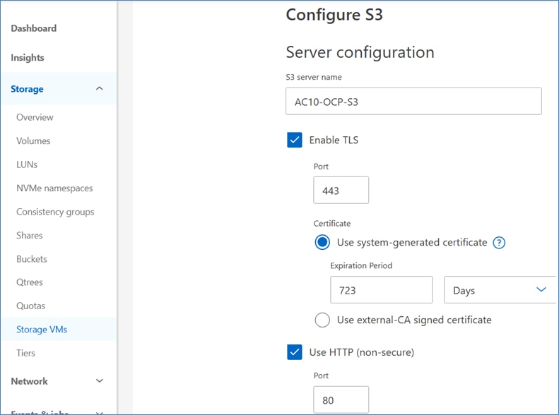
Step 3. Go to Storage > Buckets and click Add.
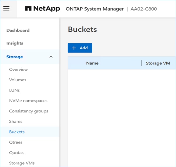
Step 4. Provide the name of the bucket, choose SVM and the size of the bucket. Click Save.
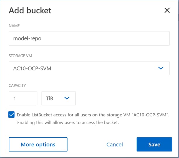
Step 5. Create one more bucket for storing pipeline artifacts.
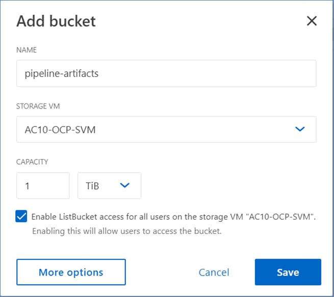
Procedure 4. Configure S3 user and group
Step 1. Go to Storage > Storage VMs. Choose the AC10-OCP-SVM, click Settings and then click under S3.
Step 2. To add a user, click Users > Add.
Step 3. Enter a name for the user.
Step 4. Click Save. The user is created and an access key and a secret key are generated for the user.
Note: Download or save the access key and secret key. They will be required for access from S3 clients.
Step 5. To add a group, click Groups and click Add.
Step 6. Enter a group name and choose the user from the list created earlier.
Step 7. Choose the FullAccess policy from the list and click Save.
Step 8. Repeat this procedure to create additional S3 buckets for Pipeline Artifacts, and so on.
The procedures detailed in this section provision the Cisco UCS compute infrastructure in the solution. This section details the following:
● Initial setup of Cisco UCS Fabric Interconnects in Intersight Managed Mode (IMM).
● Initial setup of Cisco Intersight for managing the UCS servers in this solution.
● Configure UCS domain using a Domain Profile derived from a UCS Domain Profile Template. A UCS domain is defined by a pair of Fabric Interconnects and all servers connected to it.
● Configure UCS X-Series chassis using a Chassis Profile derived from a UCS Chassis Profile Template.
● Configure UCS Servers in the chassis using Server Profiles derived from a UCS Server Profile Template.
Note: In this document, the two Cisco UCS Fabric Interconnect switches in the solution will be referred to as FI-A and FI-B rather than their actual hostnames that you will see in the screenshots below.
Initial Setup of Cisco UCS Fabric Interconnects
This section describes the initial setup of a pair of Cisco UCS Fabric Interconnects used in the solution.
Assumptions and Prerequisites
● Assumes a greenfield deployment with new Cisco UCS Fabric Interconnects that have not been configured.
● Networking and Storage should be set up prior to deploying the UCS compute infrastructure.
● Console access to Cisco UCS Fabric Interconnects.
● Collect the setup information for your environment – see Table 9.
Setup Information
Table 9 lists the setup parameters and other information necessary to do the configuration in this section. The information includes access information for management systems and devices being configured in addition to the parameters.
Table 9. Cisco UCS Fabric Interconnects: Setup Parameters and Information
| Variable/Info |
Variable Name |
Value |
Additional Information |
| FI-A Console Access Info |
N/A |
N/A |
<collect> |
| FI-B Console Access Info |
N/A |
N/A |
<collect> |
| FI Setup Method |
N/A |
console |
|
| FI Management Mode |
N/A |
intersight |
for Intersight Managed Mode (IMM) |
| FI Admin Account Info |
username |
admin |
Assumed to be the same for FI-A and FI-B. |
| password |
<specify> |
||
| FI System Name |
hostname |
AC10-UCS-FI-6536 |
hostname without the -A or -B suffix |
| FI-A Management IP |
fi-a_mgmt_ipv4_address |
10.120.0.11 |
IPv4 or IPv6 |
| FI Management Netmask |
mgmt_ipv4_netmask |
255.255.255.0 |
IPv4 or IPv6 |
| FI Management Gateway |
mgmt_ipv4_gateway |
10.120.0.254 |
IPv4 or IPv6 |
| DNS IP Address |
dns_ipv4_address |
172.20.4.53 |
IPv4 or IPv6 |
| FI-B Management IP |
fi-b_mgmt_ipv4_address |
10.120.0.12 |
IPv4 or IPv6 (must be same address type as FI-A) |
Deployment Steps
Use the setup information provided in Table 9 to do the initial setup of Cisco UCS Fabric Interconnects.
Procedure 1. Initial setup of the first UCS Fabric Interconnect in the UCS Domain
Step 1. Connect to the console port on the first Cisco UCS Fabric Interconnect.
Step 2. Power on the Fabric Interconnect. You will see the power-on self-test messages as the Fabric Interconnect boots.
Step 3. When the unconfigured system boots, it prompts you for the setup method to be used. Enter console to continue the initial setup using the console CLI.
Step 4. Enter the management mode for the Fabric Interconnect as intersight to manage the Fabric Interconnect strictly through Cisco Intersight. Also known as Intersight Managed Mode (IMM). Alternate option is ucsm to manage the Fabric Interconnects using Cisco UCS Manager (and Cisco Intersight) but this is different from managing it in IMM mode.
Step 5. Enter y to confirm that you want to continue the initial setup.
Step 6. Enter the password for the admin account. To use a strong password enter y.
Step 7. To confirm re-enter the password for the admin account.
Step 8. Enter yes to continue the initial setup for a cluster configuration.
Step 9. Enter the Fabric Interconnect fabric (either A or B ).
Step 10. Enter system name (hostname for the FIs without -A or -B in the name since it will automatically get added to distinguish between FI-A and FI-B).
Step 11. Enter the IPv4 or IPv6 address for the management port of the Fabric Interconnect.
Step 12. Enter the IPv4 subnet mask or IPv6 network prefix.
Step 13. Enter the IPv4 or IPv6 default gateway.
Step 14. Enter the IPv4 or IPv6 address for the DNS server. The address matches the address type of the management IP.
Step 15. Enter yes if you want to specify the default Domain name, or no if you do not.
Step 16. (Optional) Enter the default Domain name.
Step 17. Review the setup summary and enter yes to save and apply the settings or enter no to go through the setup again to change some of the settings.
System is coming up ... Please wait ...
UCSM image signature verification successful
---- Basic System Configuration Dialog ----
This setup utility will guide you through the basic configuration of
the system. Only minimal configuration including IP connectivity to
the Fabric interconnect and its clustering mode is performed through these steps.
Type Ctrl-C at any time to abort configuration and reboot system.
To back track or make modifications to already entered values,
complete input till end of section and answer no when prompted
to apply configuration.
Enter the configuration method. (console/gui) ? console
Enter the management mode. (ucsm/intersight)? intersight
The Fabric interconnect will be configured in the intersight managed mode. Choose (y/n) to proceed: y
Enforce strong password? (y/n) [y]: y
Enter the password for "admin":
Confirm the password for "admin": Internal CLI error: Invalid argument
Enter the switch fabric (A/B) []: B
Enter the system name: AC10-UCS-FI-6536
Physical Switch Mgmt0 IP address : 10.120.0.12
Physical Switch Mgmt0 IPv4 netmask : 255.255.255.0
IPv4 address of the default gateway : 10.120.0.254
DNS IP address : 172.20.4.53
Configure the default domain name? (yes/no) [n]:
Following configurations will be applied:
Management Mode=intersight
Switch Fabric=B
System Name=AC10-UCS-FI-6536
Enforced Strong Password=yes
Physical Switch Mgmt0 IP Address=10.120.0.12
Physical Switch Mgmt0 IP Netmask=255.255.255.0
Default Gateway=10.120.0.254
DNS Server=172.20.4.53
Apply and save the configuration (select 'no' if you want to re-enter)? (yes/no): yes
Applying configuration. Please wait.
Configuration file - Ok
XML interface to system may become unavailable since ssh is disabled
Completing basic configuration setup
Cisco UCS 6500 Series Fabric Interconnect
AC10-UCS-FI-6536-B login:
Procedure 2. Initial setup of the second UCS Fabric Interconnect in the UCS Domain
Step 1. Connect to the console port on the second Cisco UCS Fabric Interconnect.
Step 2. Power on the Fabric Interconnect. You will see the power-on self-test messages as the Fabric Interconnect boots.
Step 3. When the unconfigured system boots, it prompts you for the setup method to be used. Enter console to continue the initial setup using the console CLI.
Note: The second Fabric Interconnect should detect the first Fabric Interconnect in the cluster. If it does not, check the physical connections between the L1 and L2 ports, and verify that Fabric Interconnect is enabled for a cluster configuration.
Step 4. Enter y to add Fabric Interconnect-A to the cluster.
Step 5. Enter the admin password for Fabric Interconnect A.
Step 6. Enter the IPv4 or IPv6 address for the management port of the local Fabric Interconnect A.
Step 7. Review the setup summary and enter yes to save and apply the settings or enter no to go through the setup again to change some of the settings.
Enter the configuration method. (console/gui) ? console
Installer has detected the presence of a peer Fabric interconnect. This Fabric interconnect will be added to the cluster. Continue (y/n) ? y
Enter the admin password of the peer Fabric interconnect:
Connecting to peer Fabric interconnect... done
Retrieving config from peer Fabric interconnect... done
Peer Fabric interconnect management mode : intersight
Peer Fabric interconnect Mgmt0 IPv4 Address: 10.120.0.12
Peer Fabric interconnect Mgmt0 IPv4 Netmask: 255.255.255.0
Peer FI is IPv4 Cluster enabled. Please Provide Local Fabric Interconnect Mgmt0 IPv4 Address
Physical Switch Mgmt0 IP address : 10.120.0.11
Local fabric interconnect model(UCS-FI-6536)
Peer fabric interconnect is compatible with the local fabric interconnect. Continuing with the installer...
Apply and save the configuration (select 'no' if you want to re-enter)? (yes/no): yes
Applying configuration. Please wait.
Configuration file - Ok
XML interface to system may become unavailable since ssh is disabled
Completing basic configuration setup
2024 Jul 23 04:05:49 AC10-UCS-FI-6536-A %$ VDC-1 %$ %SECURITYD-2-FEATURE_ENABLE_DISABLE: User has enabled the feature bash-shell
2024 Jul 23 04:05:55 AC10-UCS-FI-6536-A %$ VDC-1 %$ %SECURITYD-2-FEATURE_NXAPI_ENABLE: Feature nxapi is being enabled on HTTPS.
Cisco UCS 6500 Series Fabric Interconnect
AC10-UCS-FI-6536-A login:
Initial Setup of Cisco Intersight to manage the Cisco UCS Servers in this solution
The procedures described in this section will provision the following:
● Create a Cisco Intersight account.
● Setup Licensing in Cisco Intersight.
● Configure a Resource Group for the servers in the solution.
● Configure an Organization for the servers in the solution.
● Claim Cisco UCS Fabric Interconnects in Cisco Intersight.
● Upgrade Firmware on Cisco UCS Fabric Interconnects.
Assumptions and Prerequisites
● You should have a valid cisco.com account.
● You should have Smart Licensing enabled with licenses available in a virtual account for Intersight.
● IP Access to Cisco UCS Fabric Interconnects.
● Assumes that a new organization and resource group is being provisioned in Intersight for this solution.
Setup Information
Table 10 lists the setup parameters and other information necessary to do the configuration in this section.
Table 10. Cisco Intersight: Setup Parameters and Information
| Variable/Info |
Value |
Additional Information |
| Intersight URL |
https://intersight.com |
|
| Intersight Account Name |
<specify> |
for example, RTP-B4-AC10-FlexPod |
| Cisco Smart Licensing Portal |
https://software.cisco.com/software/smart-licensing/inventory |
cisco.com username and password required |
| Smart Licensing – Registration Token |
<collect> |
|
| Licensing Tier |
Advantage |
<Essentials | Advantage> |
| Resource Group |
FPB-OAI_RG |
Note: If you plan to share this resource with other organizations or resource groups within Intersight, it is best to not specify ORG or Resource Group when claiming FI as targets in Intersight. |
| Organization |
FPB-OAI_ORG |
|
| Device ID |
<collect> |
Automation available to collect this directly from FIs |
| Claim Code |
<collect> |
Same as above |
Deployment Steps
Use the setup information listed in Table 10 to configure Intersight to manage the UCS compute infrastructure in the solution.
Procedure 1. Create a Cisco Intersight account
Note: Skip this procedure if you already have an existing Cisco Intersight that you will be using to provision and manage the infrastructure being deployed.
Step 1. Use a web browser to navigate to https://intersight.com/.
Step 2. Click Create an account.
Step 3. From the drop-down list and choose the Region (for example, US East | EU Central ) to specify where to host account.
Step 4. Click Next.
Step 5. Read and accept the General Terms license agreement. Click Next.
Step 6. Provide an Account Name. Click Create.
Step 7. In the Licensing window, choose Register Smart Licensing if you have purchased Intersight licenses.
Step 8. Using a separate browser window, collect the Product Instance Registration Token from Smart Software Licensing Portal on cisco.com. Once logged into the portal, click the Inventory tab, and then choose your Virtual Account from the drop-down list.
Step 9. Click New Token and copy the newly generated token or copy an existing token from the list.
Step 10. Paste the token into the Product Instance Registration Token box. Intersight will now attempt to license and register the newly created account with Cisco Smart Licensing Portal. This may take a few minutes. A window displays stating it was successful.
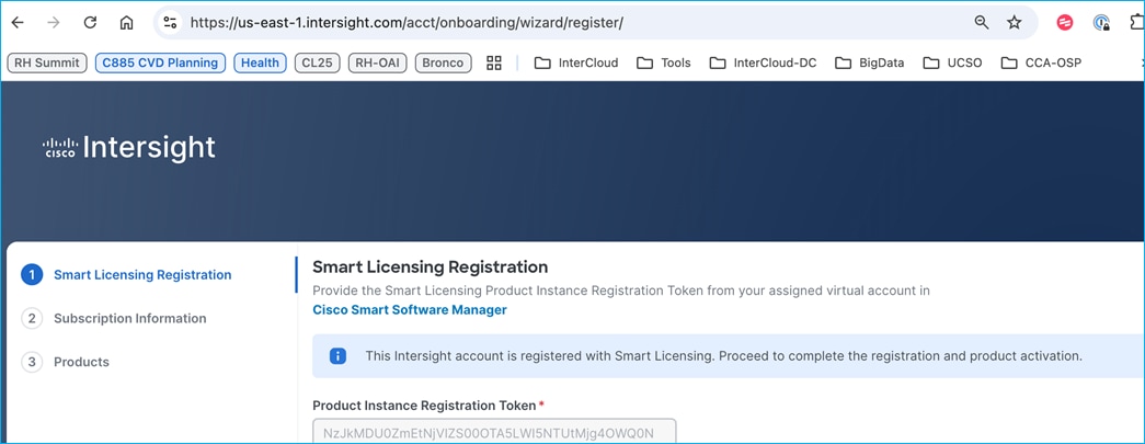
Step 11. Click Next.
Step 12. In the Subscription Information window, choose Enable Subscription Information.
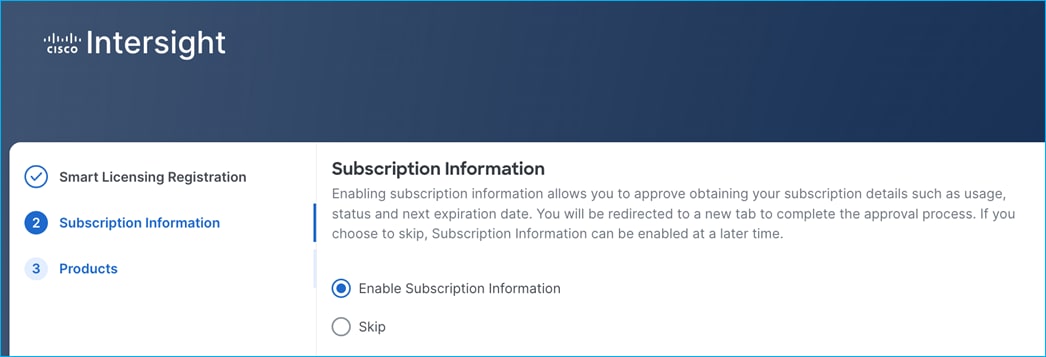
Step 13. Click Next.
Step 14. In the Products window, choose the radio buttons for the Intersight services you want to enable.
Step 15. (Optional) Choose a Default Tier from the drop-down list and check the box to Set Default Tier to all existing servers.
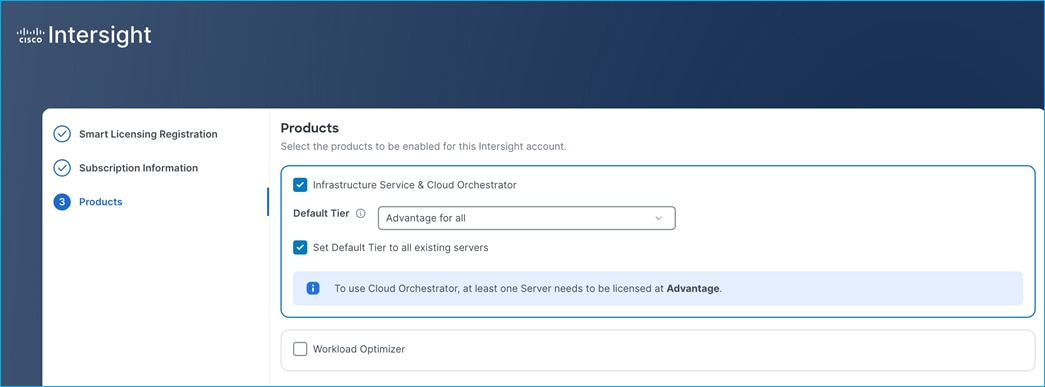
Step 16. Click Proceed. In the window, click Confirm to proceed with the selected services.
The Intersight account is now ready for provisioning and management of Cisco UCS and other data center infrastructure.
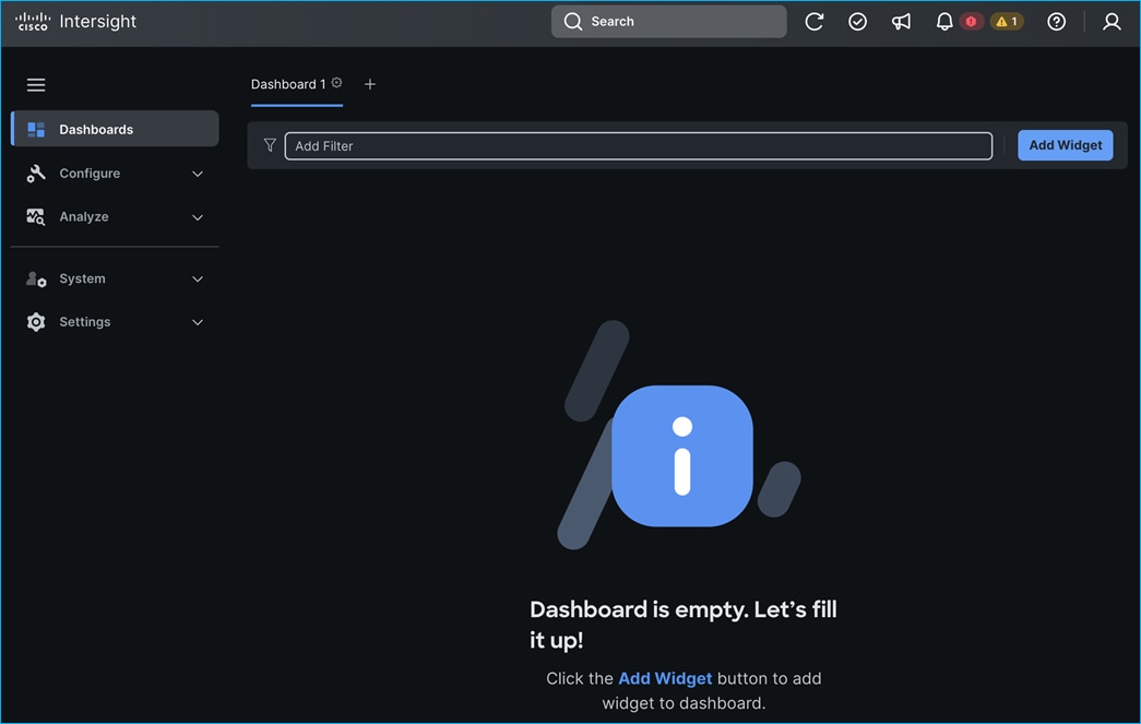
Procedure 2. Setup Licensing in Cisco Intersight
Note: Skip the procedures in this section if you’ve already enabled licensing as a part of the previous step or you have already licensed the Intersight service in the account.
Step 1. Log into the Cisco Smart Licensing portal: https://software.cisco.com/software/smart-licensing/inventory.
Step 2. Confirm that you’re using the right account. The account name should be displayed in the top-right corner of the window.
Step 3. Click the Inventory tab.
Step 4. Choose the Virtual Account from the drop-down list.
Step 5. From the General tab, click New Token to generate a new token in the Product Instance Registration Tokens section. You can also choose a pre-generated token from the list and copy that to license the Cisco Intersight service.
Step 6. Review and click Proceed in the pop-up window regarding Cisco’s Product export control and sanction laws.
Step 7. In the Create Registration Token pop-up window, provide a Description and click Create. Token.
Step 8. Click the ![]() to copy this newly created token and copy to clipboard.
to copy this newly created token and copy to clipboard.
Step 9. Log into Intersight (intersight.com) and go to System > Licensing.
Step 10. Click Smart Licensing Details and then click Register Smart Licensing.
Step 11. In Register Smart Licensing wizard, paste the previously copied token into the Product Instance Registration Token box. Click Next. This process will take a few minutes to complete.
Step 12. For Subscription Information, keep the default settings (Enable Subscription Information) and click Next.
Step 13. For Products, click Infrastructure Service & Cloud Orchestrator. Choose a Default Tier from the drop-down list. Choose Set Default Tier to all existing servers. Click Proceed.
Step 14. In the Confirm Products window, click Confirm.
Synchronizing Smart Licensing starts and takes a few minutes to complete.
If licensing completes successfully, you will see the following:
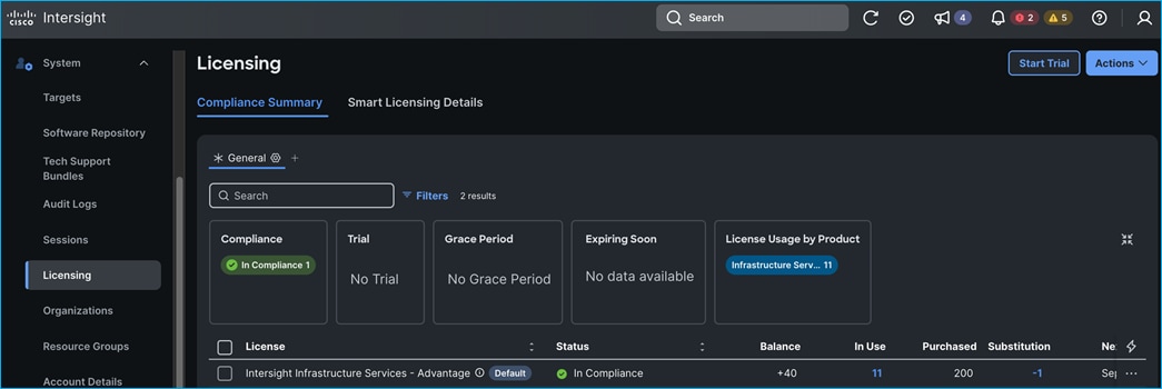
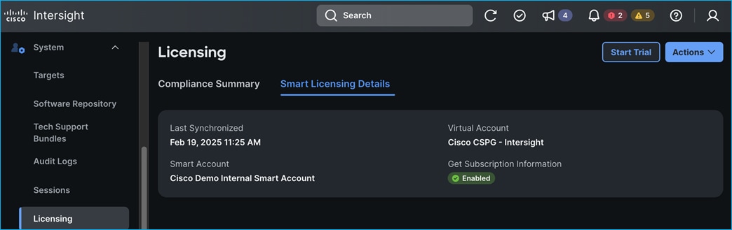
Procedure 3. Create a Resource Group in Intersight
Step 1. Go to System > Resource Groups.
Step 2. Click the + Create Resource Group box in the top-right corner of the window.
Step 3. Specify a Name and Description for the Resource Group (for example, FPB-OAI_RG).
Step 4. Under Resources click Custom.
Step 5. If the Cisco UCS Fabric Interconnects or servers have already been claimed, they can be added to the resource group by checking the box next to the claimed device – see the second screenshot below. If you’re adding a subset of servers managed by the UCS Fabric Interconnects, click the Edit icon in the Sub-Target column and choose the specific servers as shown in the first screenshot and then click Select.
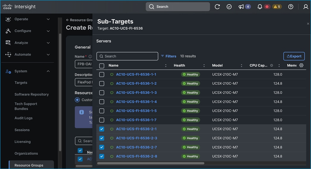
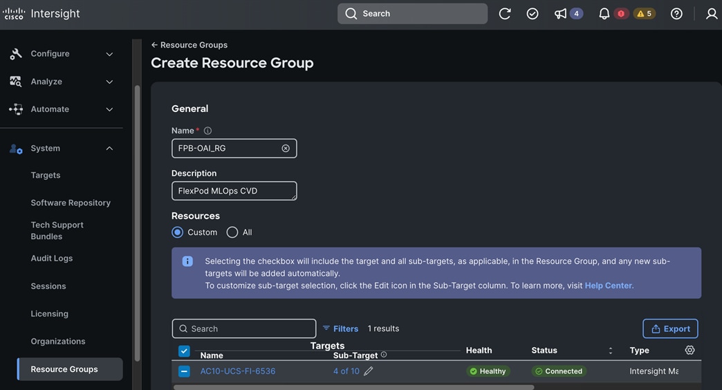
Step 6. Click Create.
Procedure 4. Create an Organization in Intersight
Step 1. Go to System > Organizations.
Step 2. Click the + Create Organization box in the top-right corner of the window.
Step 3. In the wizard, under General, specify a Name and Description for the Organization (for example, FPB-OAI_ORG).
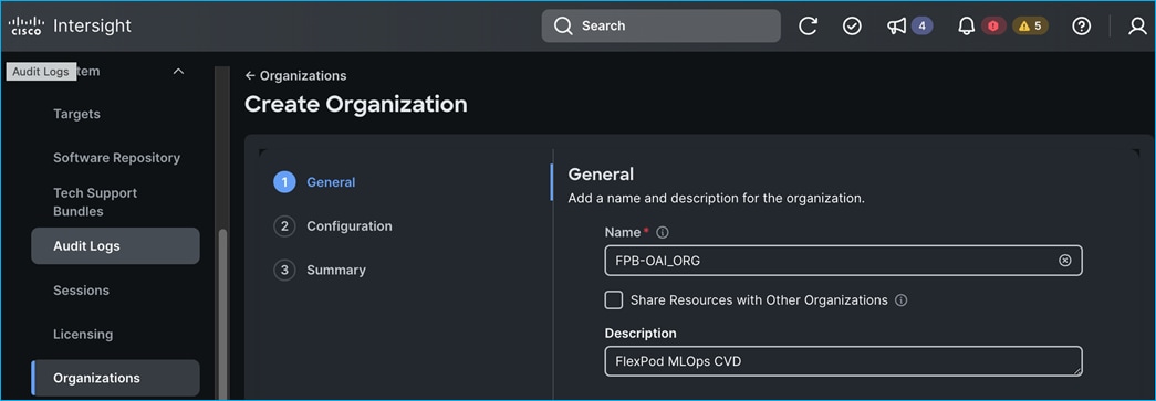
Step 4. Click Next.
Step 5. In the Configuration section, check the box for the previously created Resource Groups.
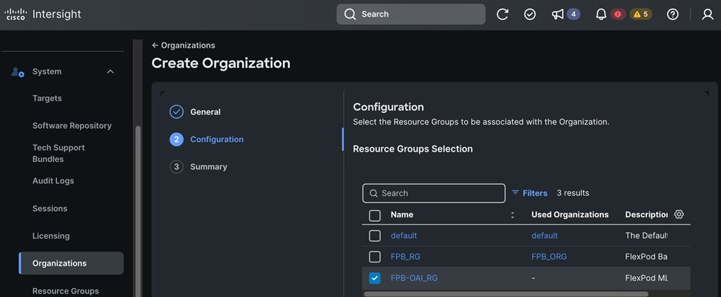
Step 6. Click Next.
Step 7. In the Summary window, verify the settings and click Create.
Procedure 5. Claim Cisco UCS Fabric Interconnects in Cisco Intersight
Note: If you plan to share this resource with other organizations or resource groups within Intersight, it is best not to specify the ORG or Resource Group when claiming FI as targets in Intersight.
Step 1. Use a web browser to log in as admin to the management IP address of Fabric Interconnect A.
Step 2. Click the Device Connector tab. The status should be Not Claimed.
Step 3. Copy the Device ID and Claim Code to claim the device in Cisco Intersight.
Step 4. Go back or log back into Cisco Intersight.
Step 5. Go to System > Targets.
Step 6. Click Claim a New Target.
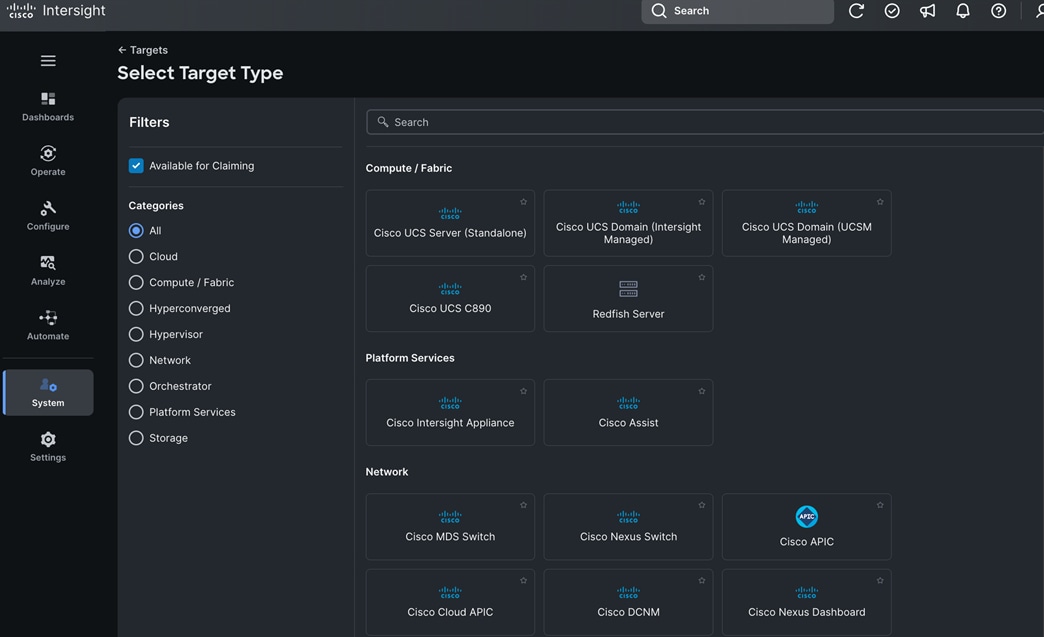
Step 7. Choose Cisco UCS Domain (Intersight Managed) and click Start.
Step 8. In the Claim Cisco UCS Domain (UCSM Managed) Target window, paste the Device ID and Claim Code copied from Cisco UCS FI-A. Choose the previously created Resource Group (see the Note above).
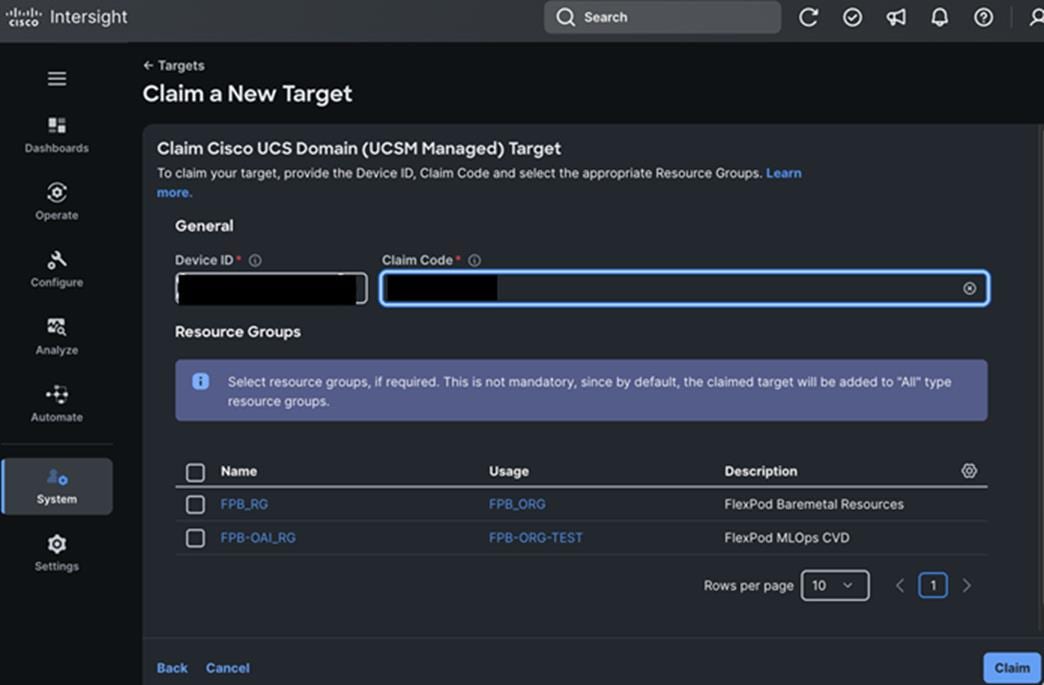
Step 9. Click Claim to claim the UCS FIs as a target in Cisco Intersight.
If the claim was successful, the Cisco UCS Fabric Interconnects display as Connected.
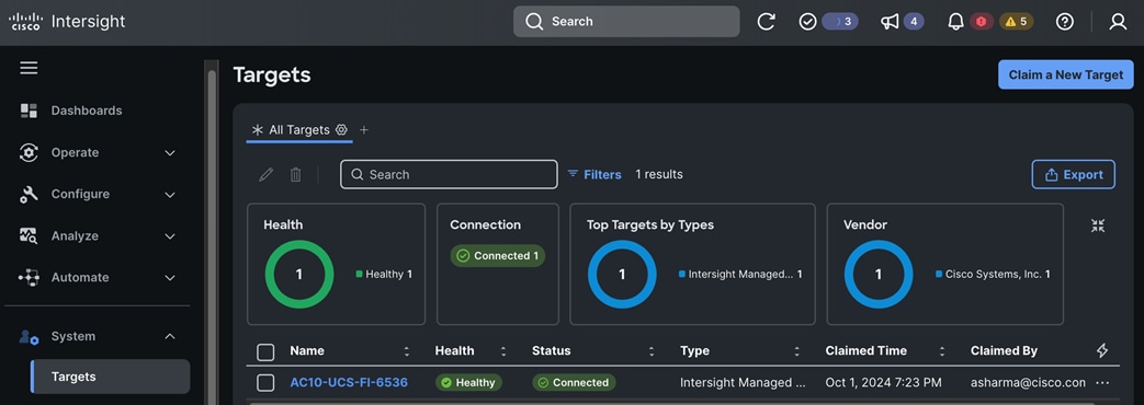
The Device Connector status on both FIs show the status as Claimed.
Procedure 6. (Optional) Upgrade Firmware on Cisco UCS Fabric Interconnects
Step 1. Use a web browser to navigate to intersight.com and log into your account.
Step 2. Go to Operate > Fabric Interconnects.
Step 3. To upgrade the Fabric Interconnect pair, choose one of the fabric interconnects and click the elipses at the end of the row and choose Upgrade Firmware from the list.
Step 4. In the Upgrade Firmware wizard, under General verify the Fabric Interconnect information.
Step 5. Click Next.
Step 6. Under Version, choose Advanced Mode to see the options available, such as enabling Fabric Interconnect Traffic Evacuation.
Step 7. Choose a version from the list to upgrade and click Next.
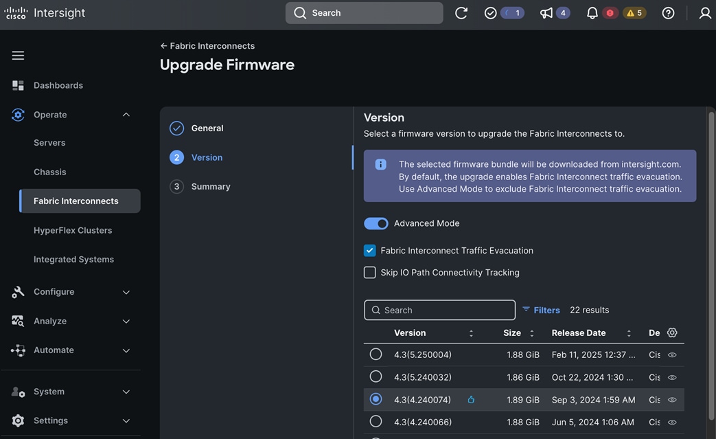
Step 8. Under Summary, verify the information and click Upgrade to start the upgrade process.
Step 9. Click Upgrade again in the Upgrade Firmware pop-up window to confirm.
Step 10. Monitor the upgrade from the Requests panel (![]() icon) since you will be prompted for permission to upgrade each FI. Follow the prompts on screen to grant permission.
icon) since you will be prompted for permission to upgrade each FI. Follow the prompts on screen to grant permission.

The upgrade upgrades both FIs in the cluster.
Step 11. Wait for the upgrade to complete before proceeding to the next step.
Configure the UCS Domain using a Domain Profile derived from a UCS Domain Profile Template
Note: A UCS domain is defined by a pair of Fabric Interconnects and all servers connected to it.
The procedures described in this section will create all policies that will be part of the UCS Domain Profile Template that will be used to derive the UCS Domain Profile. This includes:
● Create VLAN Multicast Policy
● Create VLAN Policies for FI-A and FI-B (policies for FI-A and FI-B are the same in this CVD)
● Create VSAN Policies for FI-A and FI-B (not used in this CVD)
● Create Ethernet Network Group Policies for FI-A and FI-B (policies for FI-A and FI-B are the same in this CVD)
● Create Flow Control Policy
● Create Link Aggregation Policy
● Create Link Control Policy
● Create Port Policies for FI-A and FI-B
● Create NTP Policy
● Create Syslog Policy
● Create Network Connectivity Policy
● Create SNMP Policy
● Create LDAP Policy (Optional)
● Create Certificate Management Policy (Optional)
● Create System QoS Policy
● Create Switch Control Policy
The policies are used to:
● Create a UCS Domain Profile Template using the above policies
● Derive a UCS Domain Profile from the UCS Domain Profile Template
● Deploy the UCS Domain Profile to provision the Cisco UCS domain
Assumptions and Prerequisites
● Complete the initial setup of Cisco UCS Fabric Interconnects with IP Management access.
● Valid cisco.com and Intersight accounts.
● Enable Cisco Smart Software Licensing on the Intersight account.
● Name of Intersight Organization that the UCS domain will be part of.
● Collect the setup information for your environment – see Table 11 for the required setup information.
Setup Information
Table 11. Cisco Intersight: UCS Domain Profile Template
| Parameter Type |
Parameter Name | Value |
Additional Information |
| Intersight Target Type |
Cisco UCS Domain (Intersight Managed) |
|
| Organization |
FPB-OAI_ORG |
Specified earlier |
| Tags (Optional) |
Project: FPB-OAI |
|
| Description (Optional) |
<< specify for each policy >> |
For example, UCS Domain Policy |
| UCS Domain Profile Template: UCS Domain Assignment |
||
| UCS Domain Assignment |
AC10-UCS-FI-6536 |
|
| UCS Domain Profile Template: VLAN & VSAN Configuration |
||
| Multicast Policy Name |
FPB-OAI-VLAN-MCAST_Policy |
VLAN Multicast Policy |
| UCS VLAN Policy Name |
FPB-OAI-VLAN_Policy |
|
| VLAN Name/Prefix |
||
| Auto Allow On Uplinks? |
True (Default) for all VLANs |
Disable when using Disjoint L2 designs |
| Enable VLAN Sharing? |
False (Default) for all VLANs |
For Private VLANs |
| Native VLAN |
FPB-OAI-Native_VLAN |
VLAN ID=2 |
| In-Band Mgmt. VLAN |
FPB-OAI-IB-MGMT_VLAN |
VLAN ID=1201 |
| In-Band OpenShift Cluster Mgmt. VLAN |
FPB-OAI-CLUSTER-MGMT_VLAN |
VLAN ID=1202 |
| Storage Access – S3 Object Store |
FPB-OAI-S3-OBJ_VLAN |
VLAN ID=1209 |
| Storage Access – iSCSI-A |
FPB-OAI-iSCSI-A_VLAN |
VLAN ID=3015 |
| Storage Access - iSCSI-B |
FPB-OAI-iSCSI-B_VLAN |
VLAN ID=3025 |
| Storage Access – NVMe-TCP-A |
FPB-OAI-NVMe-TCP-A_VLAN |
VLAN ID=3035 |
| Storage Access - NVMe-TCP-B |
FPB-OAI-NVMe-TCP-B_VLAN |
VLAN ID=3045 |
| Storage Access - NFS |
FPB-OAI-NFS_VLAN |
VLAN ID=3055 |
| Set Native VLAN ID |
True |
Assumes non-default below (default=1) |
| Native VLAN |
<< same as above >> |
Specified earlier, FPB-OAI-Native_VLAN=2 |
| UCS Domain Profile Template: Ports Configuration |
||
| Ethernet Network Group Policy (Optional) |
FPB-OAI-FI-A-ENG_Policy FPB-OAI-FI-B-ENG_Policy |
“Auto Allow on Uplinks” enabled by default on VLAN Policy so do not use. This is not used in this CVD. Use this only in a disjoint L2 deployment. |
| Flow Control Policy (Optional) |
FPB-OAI-Flow-Control_Policy |
Defined but using defaults |
| Priority = Auto (Default) |
Options: Auto | On | Off; Configures the Priority Flow Control (PFC) for each port to enable the no-drop behavior for the CoS defined by the System QoS Policy and an Ethernet QoS policy. If Auto and On is selected for PFC, the Receive and Send link level flow control will be Off. |
|
| Link Aggregation Policy (Optional) |
FPB-OAI-Link-Aggregation_Policy |
Defined but using defaults. |
| Suspend Individual = False (Default) |
Flag determines if the switch should suspend port if it doesn’t receive LACP PDU. |
|
| LACP Rate = Normal (Default) |
Options: Normal | Fast; Determines if LACP PDUs should be sent at a fast rate of 1sec. |
|
| Link Control Policy |
FPB-OAI-Link-Control_Policy |
|
| UDLD Admin State = Enabled (Default) |
UDLD link state . |
|
| UDLD Mode = Normal (Default) |
Options: Normal | Aggressive |
|
| FI-A Port Policy Name |
FPB-OAI-FI-A-Port_Policy |
|
| Fabric Interconnect (Switch) Model |
UCS-FI-6536 |
Other Options: UCS-FI-6454, UCS-FI-64108, UCS-FI-6536, UCSX-S9108-100G. |
| FI-A Port Policy – Unified Port (Configure ports to carry FC traffic, in addition to Ethernet) |
||
| Unified Ports – FC Ports |
N/A |
Port available for FC depends on the FI model. |
| FI-A Port Policy – Breakout Options (Configure breakout ports on FC or Ethernet) |
||
| Breakout Options |
N/A |
Available for Ethernet and Fibre Channel. |
| Ethernet |
N/A |
Defined on a per-port basis. |
| FC |
N/A |
Defined on a per-port basis. |
| FI-A Port Policy – Port Roles (Configure port roles to define traffic type on the port) |
||
| Port Roles |
Defined on a per-port basis |
Options: Appliance | Ethernet Uplink | FCoE Uplink | FC Uplink | Server | Unconfigured (Default) |
| Port Role – Port (Ethernet) |
Ports: 1/5-8, Type: Ethernet, Role: Server |
For all port roles except for port channels. |
| Auto-negotiation |
Enabled (Default) |
Disable for specific Nexus switch models. |
| Manual Chassis/Server Numbering |
Disabled (Default) |
|
| Port Role – Port (FC) |
N/A |
|
| Port Channel (PC) |
Ethernet Uplink Port Channel |
Options: Ethernet Uplink PC (Default) | FC Uplink PC | FCoE Uplink PC | Appliance PC |
| Port Channel ID |
11 |
|
| Admin Speed |
Auto (Default) |
|
| FEC |
Auto (Default) |
|
| Member Ports |
1/31-32 |
|
| Pin Groups |
N/A |
|
| FI-B Port Policy Name |
FPB-OAI-FI-B-Port_Policy |
|
| FI Switch Model |
Same as FI-A Port Policy |
|
| FI-B Port Policy – Unified Port |
Same as FI-A Port Policy |
|
| FI-B Port Policy – Breakout Options |
Same as FI-A Port Policy |
|
| FI-B Port Policy – Port Roles |
Same as FI-A Port Policy |
|
| Port Roles |
Same as FI-A Port Policy |
|
| Port Channel (PC) |
Same as FI-A Port Policy except for Port Channel ID = 12 and Ethernet Network Group Policy |
|
| Pin Groups |
N/A |
|
| UCS Domain Profile Template: UCS Domain Configuration |
||
| NTP Policy Name |
FPB-OAI-NTP_Policy |
NTP Policy Name |
| NTP Server 1 |
172.20.10.120 |
NTP Server 1 |
| NTP Server 2 |
172.20.10.119 |
NTP Server 2 |
| Timezone |
America/New_York |
Timezone |
| Syslog Policy Name |
FPB-OAI-Syslog_Policy |
Syslog Policy Name |
| Local Logging |
|
|
| File |
|
|
| Minimum Severity To Report |
Warning (Default) |
Options: Several |
| Remote Logging |
|
|
| Syslog Server 1 |
Enabled |
|
| Hostname/IP Address |
172.20.10.229 |
|
| Port |
514 (Default) |
|
| Protocol |
UDP (Default) |
|
| Minimum Severity To Report |
Warning (Default) |
|
| Syslog Server 2 |
Disabled |
|
| Network Connectivity Policy Name |
FPB-OAI-Network-Connectivity_Policy |
|
| Enabled Dynamic DNS |
Disabled (Default) |
|
| Obtain IPv4 DNS Server Addresses from DHCP |
Disabled (Default) |
|
| Preferred IPv4 DNS Server |
172.20.4.53 |
|
| Alternate IPv4 DNS Server |
172.20.4.54 |
|
| Enable IPv6 |
Disabled (Default) |
|
| SNMP Policy Name |
FPB-OAI-SNMP_Policy |
Defined in Chassis Policy. |
| Enable SNMP |
Yes |
|
| Version |
Both v2c and v3(Default) |
Options: v2c Only | v3 Only | Both v2c and v3 |
| Configuration |
|
|
| SNMP Port |
161 (Default) |
Range: 1-65535 |
| System Contact |
Flexpod-admin@cisco.com |
|
| System Location |
RTP-AC10 |
|
| Access Community String |
readwrite |
Community name or username (SNMP v3) |
| SNMP Community Access |
Disabled (Default) |
|
| Trap Community String |
|
SNMP Community (SNMP v2c) |
| SNMP Engine Input ID |
|
|
| SNMP Users |
|
|
| Add SNMP User |
|
|
| Name |
snmpadmin |
|
| Security Level |
AuthPriv |
|
| Auth Type |
SHA |
|
| Auth Password |
<specify> |
|
| Auth Password Confirmation |
<specify> |
|
| Privacy Type |
AES |
|
| Privacy Password |
<specify> |
|
| Privacy Password Confirmation |
<specify> |
|
| Add SNMP Trap Destination |
|
|
| LDAP Policy Name |
N/A |
Not defined or used in this CVD. |
| Certificate Management Name |
N/A |
Not defined or used in this CVD. Add Certificates (IMC – Certificate, Private Key, Root CA - Certificate Name, Certificate). |
| System QoS Policy Name |
FPB-OAI-System-QoS_Policy |
|
| Best Effort |
Enabled (Default) |
|
| CoS |
Any (Default) |
|
| Weight |
5 |
Options: 0-10 |
| Allow Packet Drops |
Yes |
|
| MTU |
9216 |
|
| Switch Control Policy Name |
FPB-OAI-System-Control_Policy |
|
| Switching Mode |
Ethernet End Host |
|
| All other parameters |
Default settings used |
|
| Create UCS Domain Profile Template |
||
| UCS Domain Profile Template Name |
FPB-OAI-Domain-Profile_Template |
|
Deployment Steps
Use the setup information provided in this section to configure the policies for the UCS domain consisting of the two Cisco UCS Fabric Interconnects. The policies will be part of the UCS Domain Profile Template which will be used to derive the UCS Domain Profile to configure this specific UCS Domain.
The following procedures configure policies that are used in the VLAN & VSAN Configuration section of Create UCS Domain Profile Template wizard.
Procedure 1. Create (VLAN) Multicast Policy
Step 1. Use a web browser to navigate to intersight.com and log into your account.
Step 2. Go to Configure > Policies.
Step 3. Click Platform Type – either All or UCS Domain.
Step 4. Choose Multicast Policy.
Step 5. Click Start.
Step 6. From the Policies > Multicast Policy window, in the General section, for Organization, choose the previously created organization from the drop-down list.
Step 7. For Name, specify a name for this policy.
Step 8. (Optional) For Set Tags, specify value in key:value format.
Step 9. (Optional) For Description, specify a description for this policy.
Step 10. Click Next.
Step 11. In Policy Details section, choose the default settings:
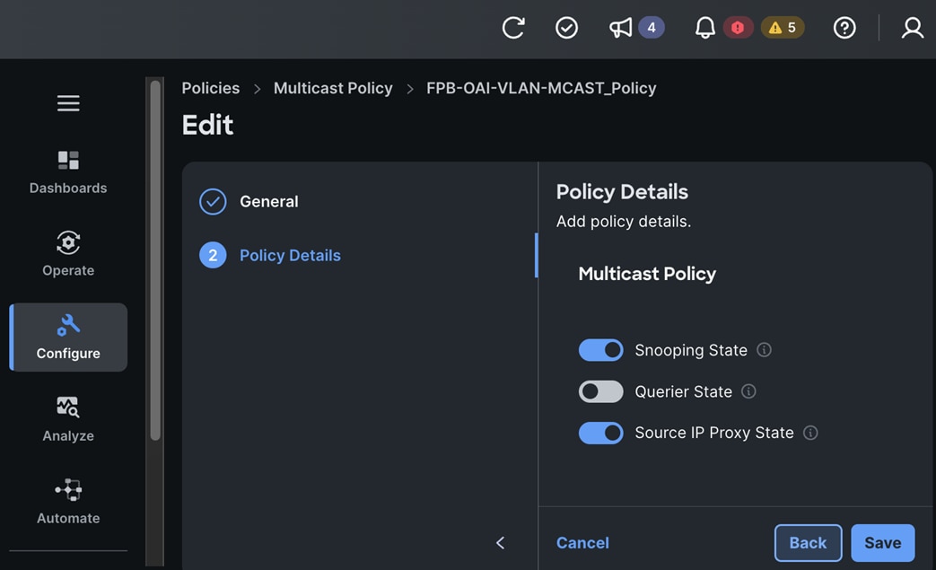
Step 12. Click Create. A pop-up message displays stating the policy was created successfully.
Procedure 2. Create a VLAN Policy
Step 1. Use a web browser to navigate to intersight.com and log into your account.
Step 2. Go to Configure > Policies.
Step 3. Choose Platform Type – either All or UCS Domain.
Step 4. Click VLAN.
Step 5. Click Start.
Step 6. From the Policies > VLAN window, in the General section for Organization, choose the previously created organization from the drop-down list.
Step 7. For Name, specify a name for this policy.
Step 8. (Optional) For Set Tags, specify value in key:value format.
Step 9. (Optional) For Description, specify a description for this policy.
Step 10. Click Next.
Step 11. In the Policy Details section, click Add VLANs.
Step 12. In the Create VLAN window, specify a Name/Prefix and VLAN ID for the native VLAN. Keep the remaining defaults.
Step 13. For Multicast Policy*, click Select Policy and choose the previously configured multicast policy.
Step 14. Click Add to add the VLAN.
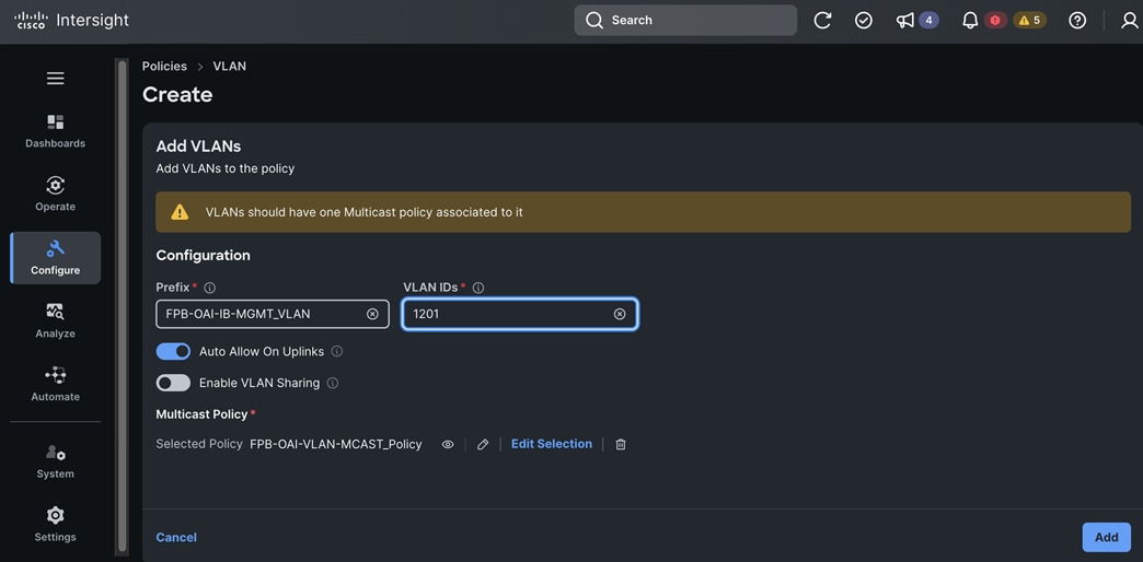
Step 15. Repeat steps 11 – 14 to add the remaining VLANs including the Native VLAN if it is different from the default (vlan=1).
Step 16. If using a non-default native VLAN, scroll down and check the box for Set Native VLAN ID and specify the VLAN ID for the native VLAN. This VLAN should be one of the previously created VLANs.
Step 17. Click Create. A pop-up message displays stating the policy was created successfully.
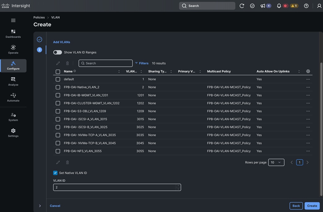
Note: The next set of procedures will configure policies that will be used in the Ports Configuration section of the Create UCS Domain Profile Template wizard.
Procedure 3. Create FI-A Ethernet Network Group Policy
Note: Skip this section unless you are using a Disjoint L2 configuration on Fabric Interconnects.
Step 1. Use a web browser to navigate to intersight.com and log into your account.
Step 2. Go to Configure > Policies.
Step 3. Choose Platform Type – either All or UCS Domain.
Step 4. Choose Ethernet Network Group Policy.
Step 5. Click Start.
Step 6. From the Policies > Ethernet Network Group window, in the General section, for Organization, choose the previously created organization from the drop-down list.
Step 7. For Name, specify a name for this policy.
Step 8. (Optional) For Set Tags, specify value in key:value format.
Step 9. (Optional) For Description, specify a description for this policy.
Step 10. Click Next.
Step 11. In Policy Details section, click Add VLANs and choose From Policy from the drop-down list.
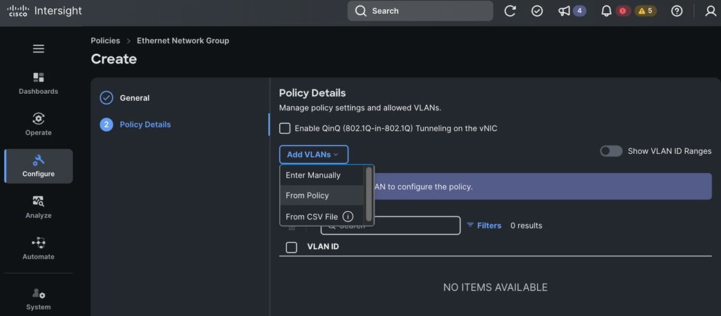
Step 12. From the Select Policy window, choose the previously created VLAN policy.
Step 13. Click Next.
Step 14. You should now see all VLANs from the VLAN policy listed. Check the box to select all VLANs.
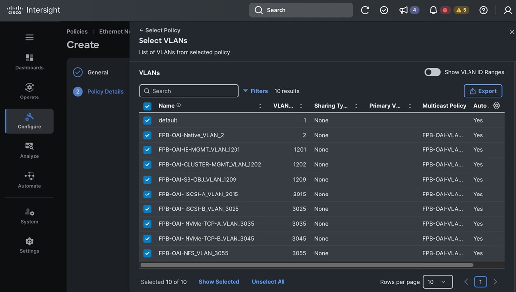
Step 15. Click Select.
Step 16. In the Policy Details window, choose the VLAN ID for native VLAN, click the elipses and choose Set Native VLAN.
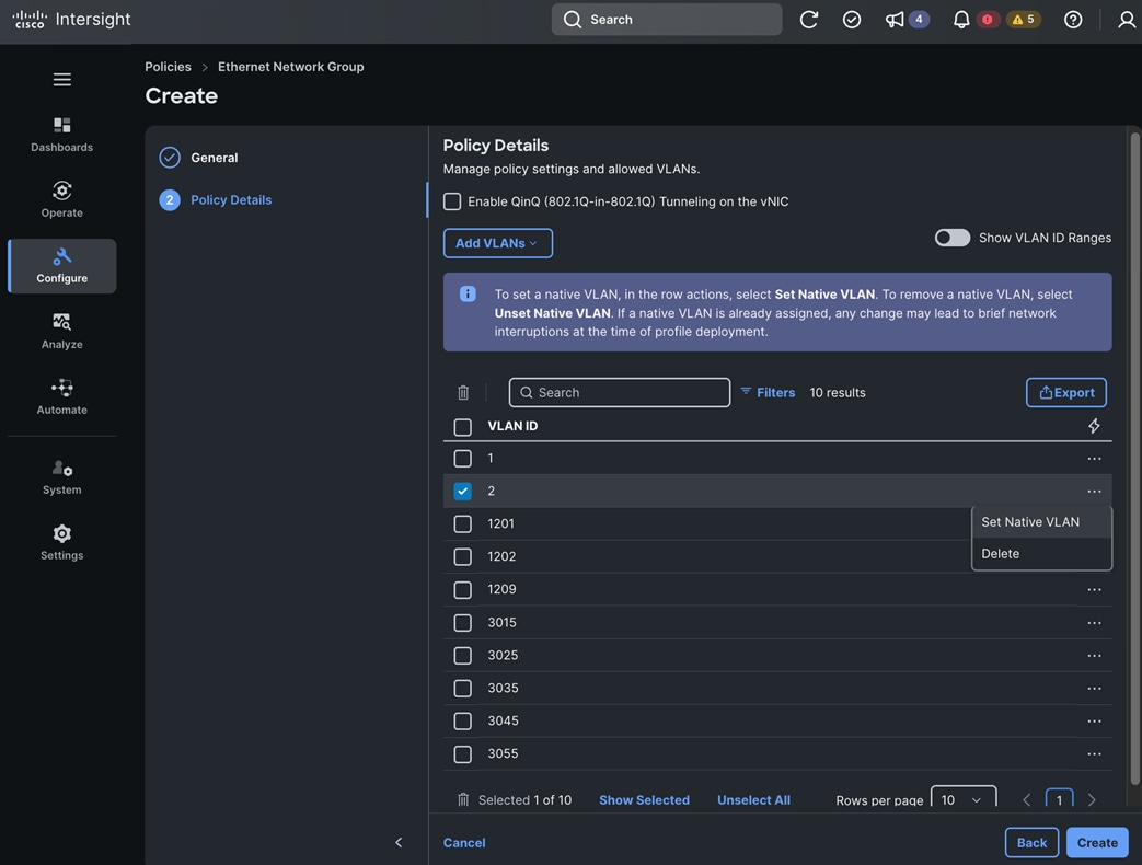
Step 17. Click Create. A pop-up message displays stating the policy was created successfully.
Procedure 4. Create FI-B Ethernet Network Group Policy
Note: Skip this section unless you are using a Disjoint L2 configuration on Fabric Interconnects.
Step 1. Use a web browser to navigate to intersight.com and log into your account.
Step 2. Go to Configure > Policies.
Step 3. Choose Platform Type – either All or UCS Domain.
Step 4. Choose Ethernet Network Group.
Step 5. Click Start.
Step 6. From the Policies > Ethernet Network Group window, in the General section, for Organization, choose the previously created organization from the drop-down list.
Step 7. For Name, specify a name for this policy.
Step 8. (Optional) For Set Tags, specify value in key:value format.
Step 9. (Optional) For Description, specify a description for this policy.
Step 10. Click Next.
Step 11. In Policy Details section, click Add VLANs and choose From Policy from the drop-down list.

Step 12. From the Select Policy window, choose the previously created VLAN policy.
Step 13. Click Next.
Step 14. You should now see all VLANs from the VLAN policy listed. Check the box for all VLANs.

Step 15. Click Select.
Step 16. In the Policy Details window, choose VLAN ID for native VLAN, click the elipses and choose Set Native VLAN.
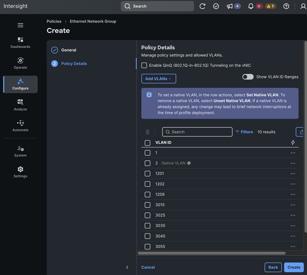
Step 17. Click Create. A pop-up message displays stating the policy was created successfully.
Procedure 5. Create Flow Control Policy
Step 1. Use a web browser to navigate to intersight.com and log into your account.
Step 2. Go to Configure > Policies.
Step 3. Choose Platform Type – either All or UCS Domain.
Step 4. Choose Flow Control.
Step 5. Click Start.
Step 6. From the Policies > Flow Control window, in the General section, for Organization, choose the previously created organization from the drop-down list.
Step 7. For Name, specify a name for this policy.
Step 8. (Optional) For Set Tags, specify value in key:value format.
Step 9. (Optional) For Description, specify a description for this policy.
Step 10. Click Next.
Step 11. In Policy Details section, keep the default settings.
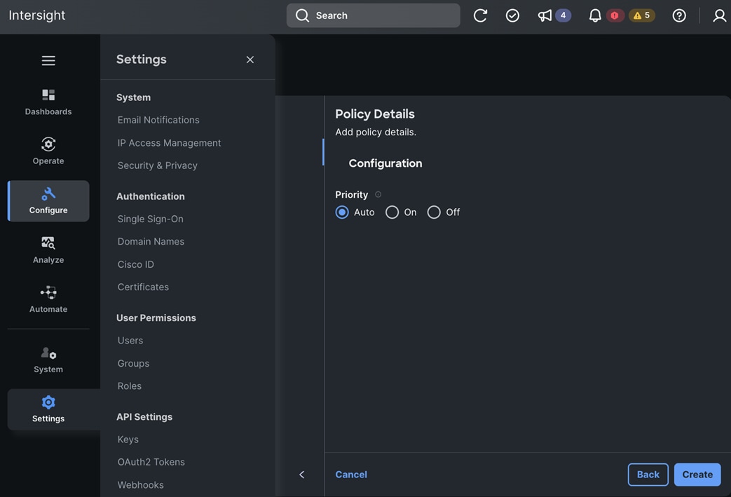
Step 12. Click Create. A pop-up message displays stating the policy was created successfully.
Procedure 6. Create Link Aggregation Policy
Step 1. Use a web browser to navigate to intersight.com and log into your account.
Step 2. Go to Configure > Policies.
Step 3. Choose Platform Type – either All or UCS Domain.
Step 4. Choose Link Aggregation.
Step 5. Click Start.
Step 6. From the Policies > Link Aggregation window, in the General section, for Organization, choose the previously created organization from the drop-down list.
Step 7. For Name, specify a name for this policy.
Step 8. (Optional) For Set Tags, specify value in key:value format.
Step 9. (Optional) For Description, specify a description for this policy.
Step 10. Click Next.
Step 11. In Policy Details section, keep the default settings.
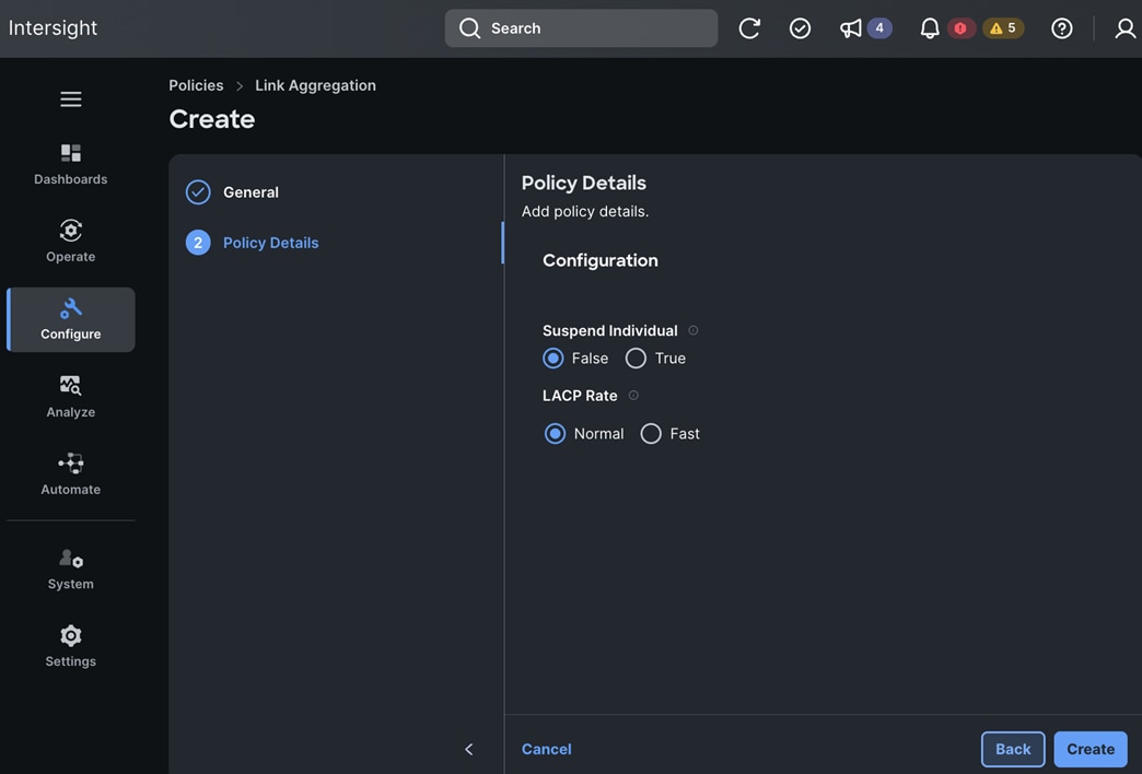
Step 12. Click Create. A pop-up message displays stating the policy was created successfully.
Procedure 7. Create Link Control Policy
Step 1. Use a web browser to navigate to intersight.com and log into your account.
Step 2. Go to Configure > Policies.
Step 3. Choose Platform Type – either All or UCS Domain.
Step 4. Choose Link Control.
Step 5. Click Start.
Step 6. From the Policies > Link Control window, in the General section, for Organization, choose the previously created organization from the drop-down list.
Step 7. For Name, specify a name for this policy.
Step 8. (Optional) For Set Tags, specify value in key:value format.
Step 9. (Optional) For Description, specify a description for this policy.
Step 10. Click Next.
Step 11. In Policy Details section, keep the default settings.
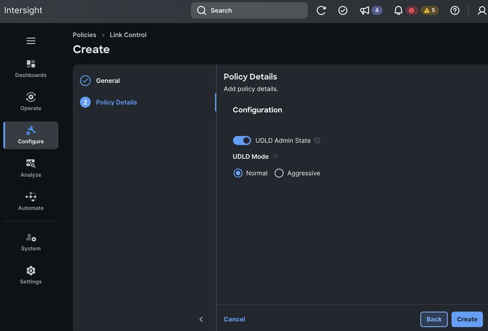
Step 12. Click Create. A pop-up message displays stating the policy was created successfully.
Procedure 8. Create Port Policy for FI-A
Step 1. Use a web browser to navigate to intersight.com and log into your account.
Step 2. Go to Configure > Policies.
Step 3. Choose Platform Type – either All or UCS Domain.
Step 4. Choose Port.
Step 5. Click Start.
Step 6. From the Policies > Port window, in the General section, for Organization, choose the previously created organization from the drop-down list.
Step 7. For Name, specify a name for this policy.
Step 8. For Fabric Interconnect Model, choose a model from the drop-down list.
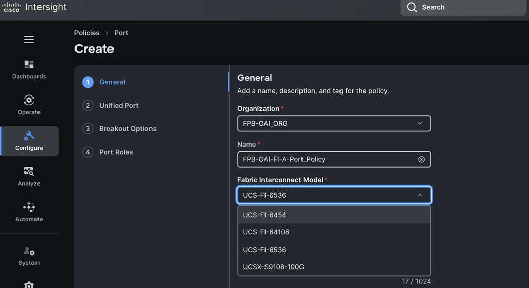
Step 9. (Optional) For Set Tags, specify value in key:value format.
Step 10. (Optional) For Description, specify a description for this policy.
Step 11. Click Next.
Step 12. In the Unified Ports section, leave the slider as is since you are not configuring the Fibre Channel (FC) ports in this CVD. All ports in this FI will be Ethernet ports.
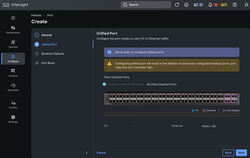
Step 13. Click Next.
Step 14. In the Breakout Options section, if using breakout ports, configure it now otherwise keep the default settings.
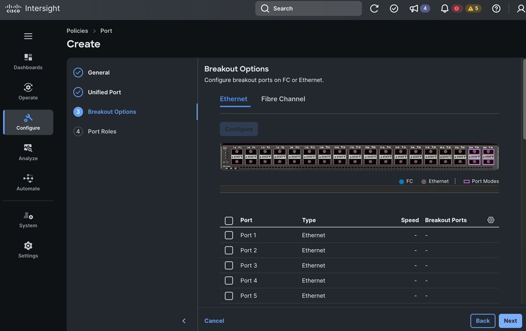
Step 15. Click Next.
Step 16. In the Port Roles section, click the Port Roles.
Step 17. Scroll down and choose the server ports to configure. When the checkboxes for the relevant ports are selected, scroll up and click Configure.
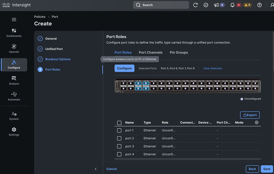
Step 18. In the Configure Ports window, for the Role, choose Server from the drop-down list.
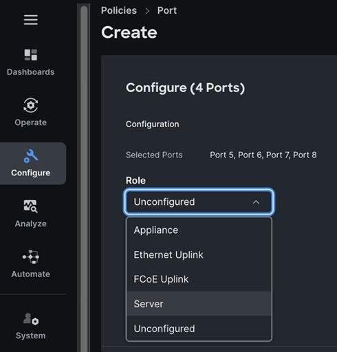
Step 19. For the remaining settings, keep the default settings.
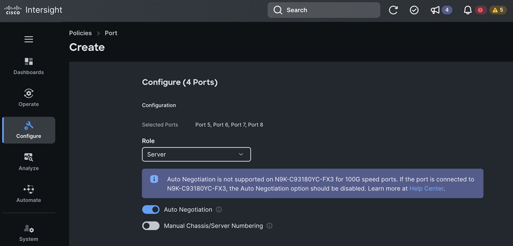
Step 20. Click Save.
Step 21. In the Port Roles section, click the Port Channels.
Step 22. Click Create Port Channel.
Step 23. In the Create Port Channel window, choose Ethernet Uplink Port Channel from the drop-down list.
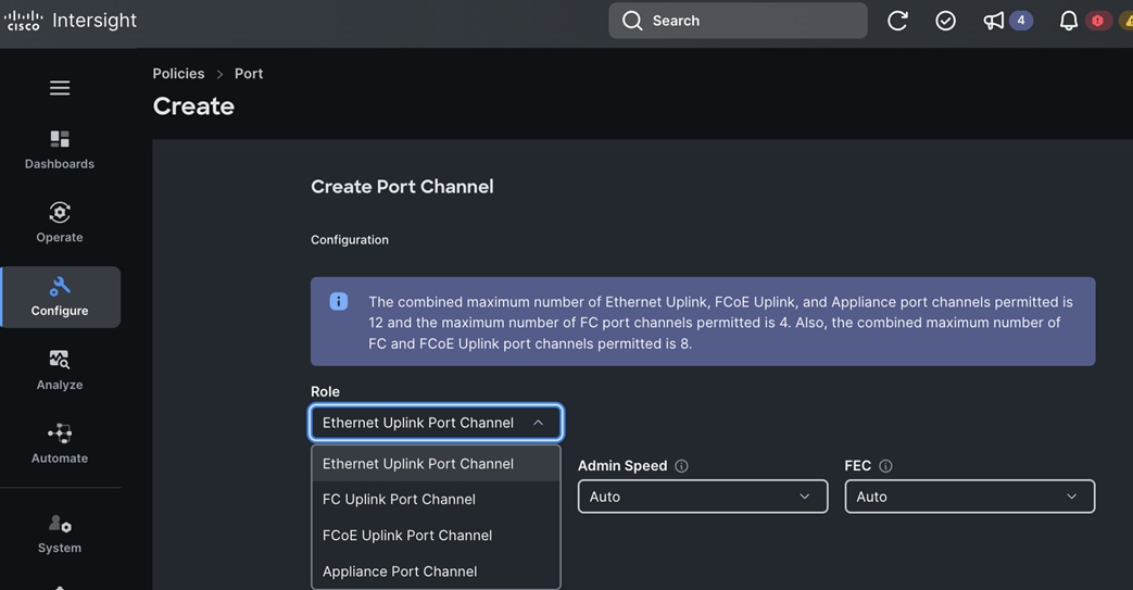
Step 24. For the Port Channel ID, specify a unique ID; the ID is local to the FI. It does not need to match the ID on the switch to which it connects.
Step 25. For Admin Speed, keep the default settings.
Step 26. For FEC, keep the default settings.
Step 27. For Ethernet Network Group, keep the default settings.
CAUTION!: If using Disjoint L2, click Select Policies and choose the previously configured policy.Only use this in a Disjoint L2 deployment.
Step 28. For Flow Control, click Select Policy and choose the previously configured policy.
Step 29. For Link Aggregation, click Select Policy and choose the previously configured policy.
Step 30. For Link Control, click Select Policy and choose the previously configured policy.
Step 31. In the Select Member Ports section, scroll down and check the box next to the uplink ports that should be part of this port channel.
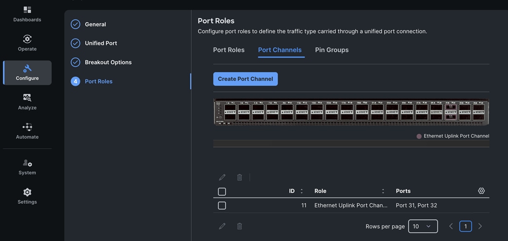
Step 32. Click Create. A pop-up message displays stating the policy was created successfully.
Procedure 9. Create Port Policy for FI-B
Step 1. Repeat the steps in Procedure 8. Create Port Policy for FI-A to configure a port policy for FI-B.
Note: In this CVD, all parameters are identical to FI-A except for the Port Channel ID and Ethernet Network Group Policy Name.
Note: The next set of procedures configure the policies that are used in the UCS Domain Configuration section of the Create UCS Domain Profile Template wizard.
Procedure 10. Create NTP Policy
Step 1. Use a web browser to navigate to intersight.com and log into your account.
Step 2. Go to Configure > Policies.
Step 3. Choose Platform Type – either All or UCS Domain.
Step 4. Choose NTP.
Step 5. Click Start.
Step 6. From the Policies > NTP window, in the General section, for Organization, choose the previously created organization from the drop-down list.
Step 7. For Name, specify a name for this policy.
Step 8. (Optional) For Set Tags, specify value in key:value format.
Step 9. (Optional) For Description, specify a description for this policy.
Step 10. Click Next.
Step 11. In Policy Details section, choose Enable NTP.
Step 12. Specify NTP server IP addresses and add more as needed.
Step 13. Choose a Time zone from the drop-down list.
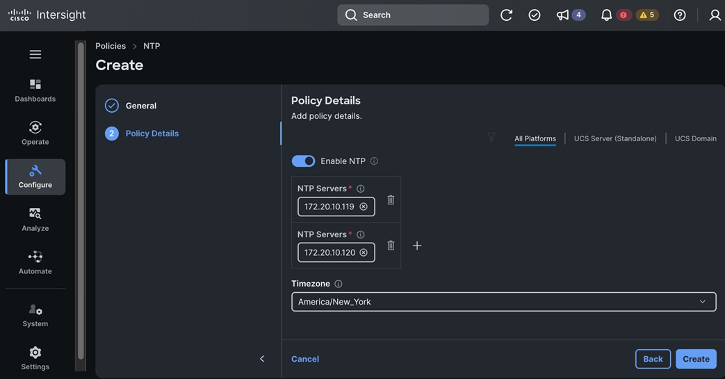
Step 14. Click Create. A pop-up message displays stating the policy was created successfully.
Procedure 11. Create a Syslog Policy
Step 1. Use a web browser to navigate to intersight.com and log into your account.
Step 2. Go to Configure > Policies.
Step 3. Choose Platform Type – either All or UCS Domain.
Step 4. Choose Syslog.
Step 5. Click Start.
Step 6. From the Policies > Syslog window, in the General section for Organization, choose previously created organization from the drop-down list.
Step 7. For Name, specify a name for this policy.
Step 8. (Optional) For Set Tags, specify value in key:value format.
Step 9. (Optional) For Description, specify a description for this policy.
Step 10. Click Next.
Step 11. In Policy Details section, expand Local Logging > File. For Minimum Severity to Report, choose from the options in the drop-down list.
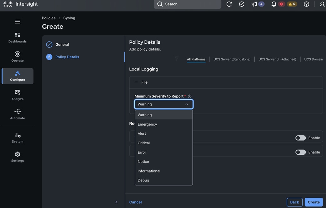
Step 12. For Remote Logging, enable Syslog Server 1 and provision the IP address, Port, Protocol and Minimum Severity To Report for the syslog server. Repeat this step if you’re using a second syslog server.
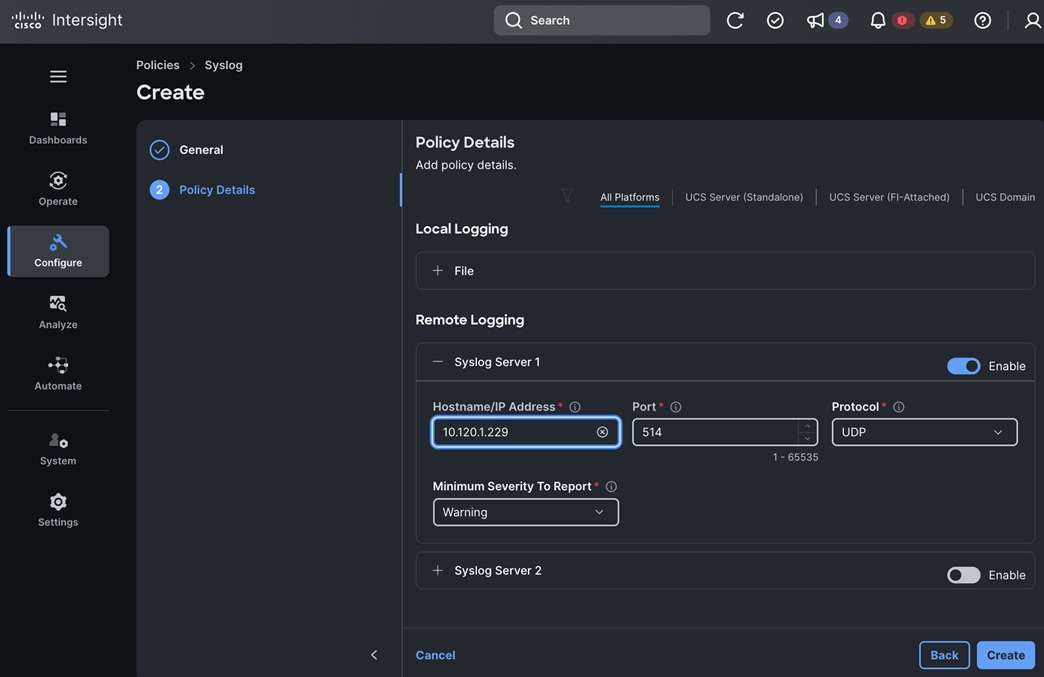
Step 13. Click Create. A pop-up message displays stating the policy was created successfully.
Procedure 12. Create a Network Connectivity Policy
Step 1. Use a web browser to navigate to intersight.com and log into your account.
Step 2. Go to Configure > Policies.
Step 3. Choose Platform Type – either All or UCS Domain.
Step 4. Choose Network Connectivity.
Step 5. Click Start.
Step 6. From the Policies > Network Connectivity window, in the General section, for Organization, choose the previously created organization from the drop-down list.
Step 7. For Name, specify a name for this policy.
Step 8. (Optional) For Set Tags, specify value in key:value format.
Step 9. (Optional) For Description, specify a description for this policy.
Step 10. Click Next.
Step 11. In Policy Details section, specify Preferred IPv4 DNS Server and Alternate IPv4 DNS Server IP addresses. Keep the default setting for all fields.
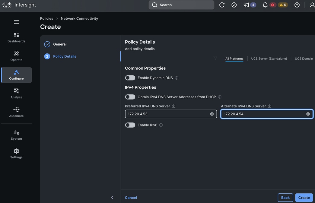
Step 12. Click Create. A pop-up message displays stating the policy was created successfully.
Procedure 13. Create a SNMP Policy
Step 1. Use a web browser to navigate to intersight.com and log into your account.
Step 2. Go to Configure > Policies.
Step 3. Choose Platform Type – either All or UCS Domain.
Step 4. Choose SNMP.
Step 5. Click Start.
Step 6. From the Policies > SNMP window, in the General section, for Organization, choose the previously created organization from the drop-down list.
Step 7. For Name, specify a name for this policy.
Step 8. (Optional) For Set Tags, specify value in key:value format.
Step 9. (Optional) For Description, specify a description for this policy.
Step 10. Click Next.
Step 11. In Policy Details section, enable SNMP.
Step 12. Choose the SNMP version and in the Configuration section, configure the parameters as needed:
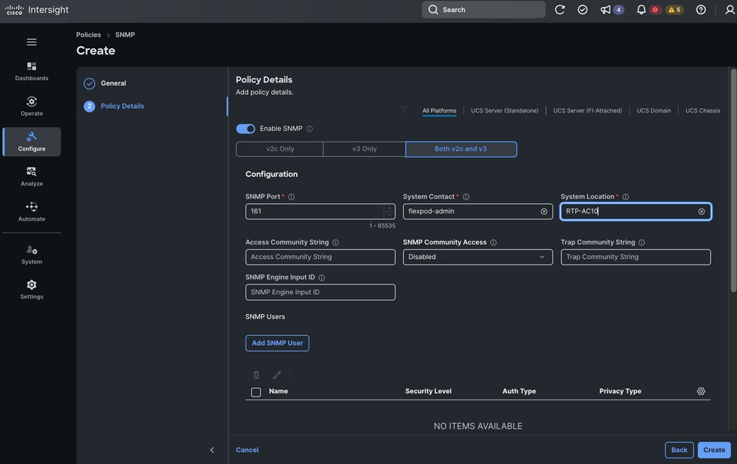
Step 13. In the Add SNMP User section, add SNMP Users as needed.
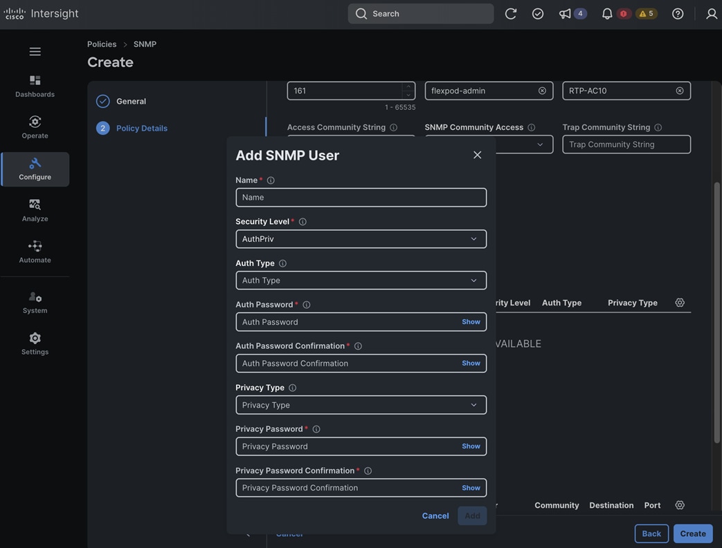
Step 14. In the Add SNMP Trap Destination section, add SNMP Trap destination as needed.
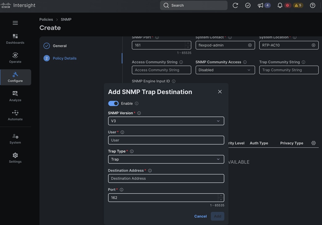
Step 15. Click Create. A pop-up message displays stating the policy was created successfully.
Procedure 14. Create a System QoS Policy
Step 1. Use a web browser to navigate to intersight.com and log into your account.
Step 2. Go to Configure > Policies.
Step 3. Choose Platform Type – either All or UCS Domain.
Step 4. Choose System QoS.
Step 5. Click Start.
Step 6. From the Policies > System QoS window, in the General section, for Organization, choose the previously created organization from the drop-down list.
Step 7. For Name, specify a name for this policy.
Step 8. (Optional) For Set Tags, specify value in key:value format.
Step 9. (Optional) For Description, specify a description for this policy.
Step 10. Click Next.
Step 11. In Policy Details section, specify the QoS Policies for Best Effort policy as shown below:
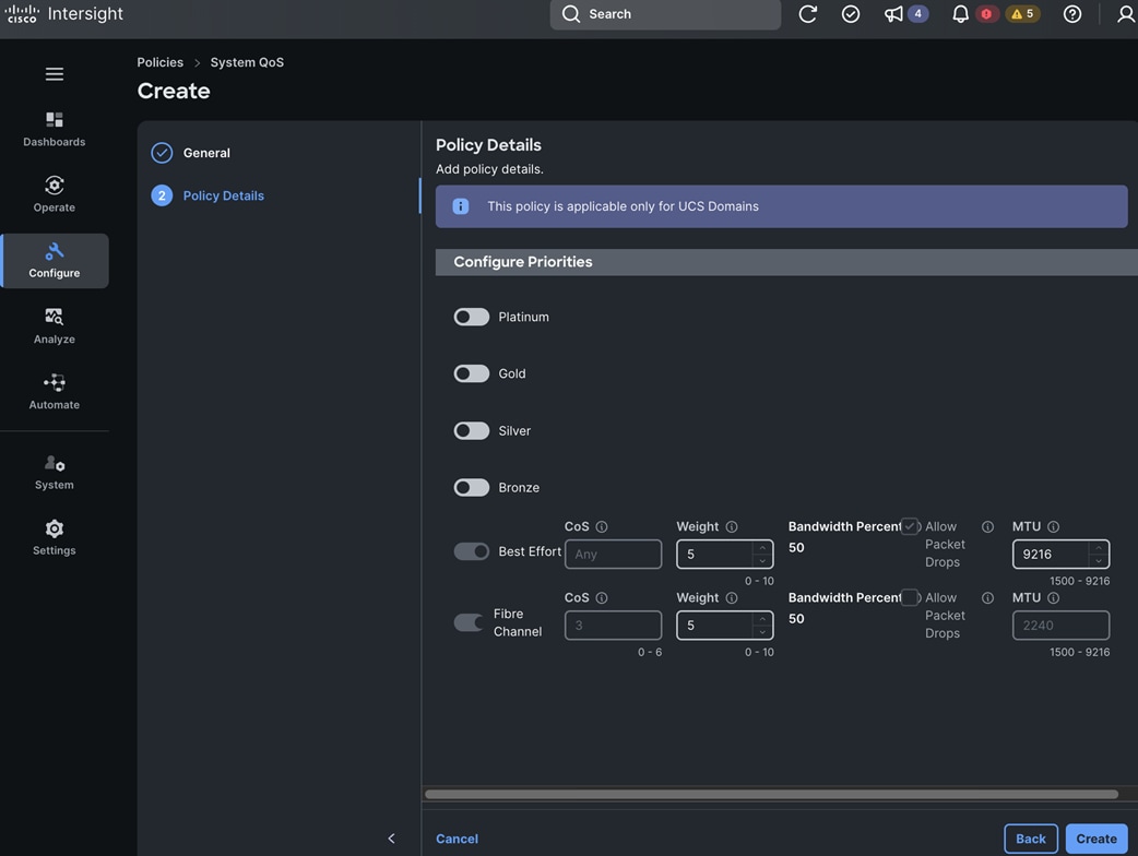
Step 12. Click Create. A pop-up message displays stating the policy was created successfully.
Procedure 15. Create a Switch Control Policy
Step 1. Use a web browser to navigate to intersight.com and log into your account.
Step 2. Go to Configure > Policies.
Step 3. Choose Platform Type – either All or UCS Domain.
Step 4. Choose Switch Control.
Step 5. Click Start.
Step 6. From the Policies > Switch Control window, in the General section, for Organization, choose the previously created organization from the drop-down list.
Step 7. For Name, specify a name for this policy.
Step 8. (Optional) For Set Tags, specify value in key:value format.
Step 9. (Optional) For Description, specify a description for this policy.
Step 10. Click Next.
Step 11. In Policy Details section, verify that Switching Mode > Ethernet is set to End Host Mode as shown below. Kepp the default settings.
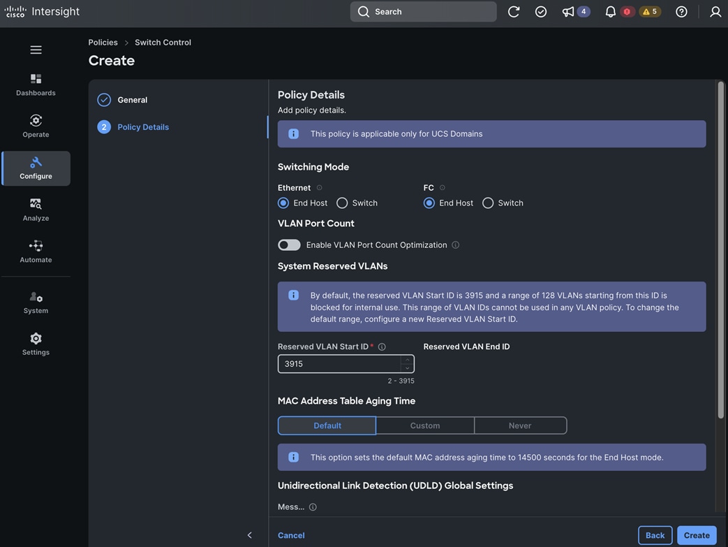
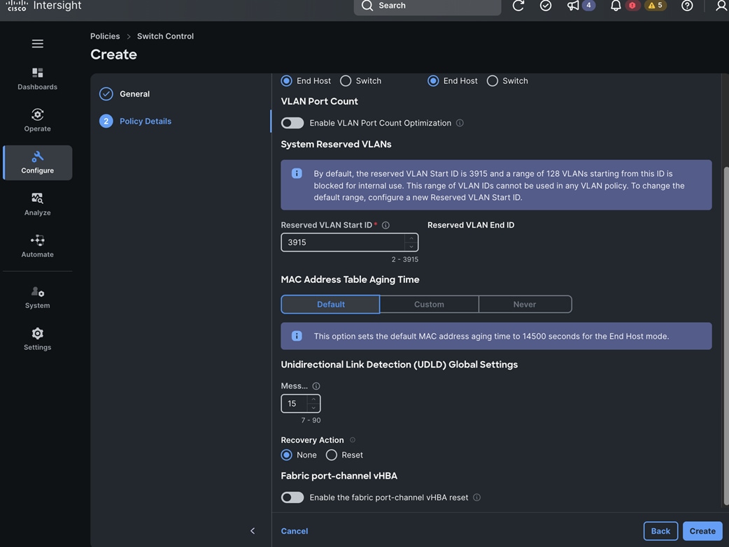
Step 12. Click Create. A pop-up message displays stating the policy was created successfully.
Note: The next set of procedures will create a Cisco UCS Domain Profile Template using the policies created in the previous procedures.
Procedure 16. Create a UCS Domain Profile Template: General
Step 1. Use a web browser to navigate to intersight.com and log in to your account.
Step 2. Go to Configure > Templates.
Step 3. Choose UCS Domain Profile Templates.
Step 4. Click Create UCS Domain Profile Template.
Step 5. From the Create UCS Domain Profile Template window, in the General section, for Organization, choose the previously created organization from the drop-down list.
Step 6. For Name, specify a name for this policy.
Step 7. (Optional) For Set Tags, specify value in key:value format.
Step 8. (Optional) For Description, specify a description for this policy.
Step 9. Click Next.
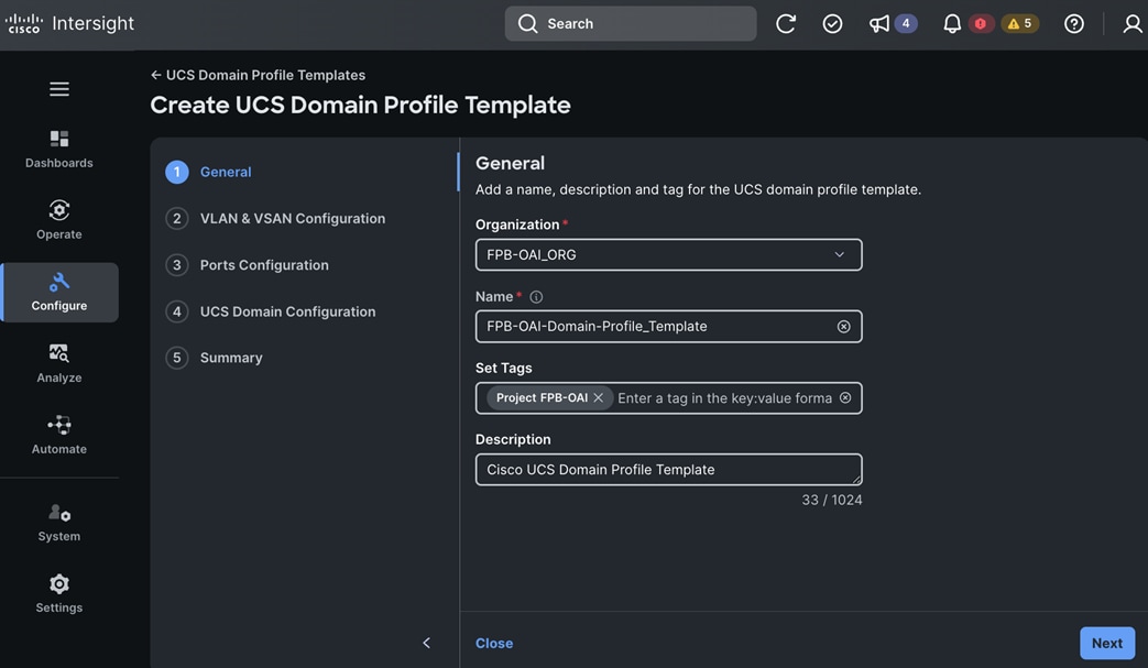
Procedure 17. Create a UCS Domain Profile Template: VLAN & VSAN Configuration for FI-A and FI-B
Step 1. For VLAN & VSAN Configuration, under Fabric Interconnect A, for VLAN Configuration, click Select Policy.
Step 2. In the Select Policy window, choose the previously created VLAN Policy for FI-A (same as FI-B VLAN policy in this CVD).
Step 3. For VLAN & VSAN Configuration, under Fabric Interconnect B, for VLAN Configuration, click Select Policy.
Step 4. In the Select Policy window, choose the previously created VLAN Policy for FI-B (same as FI-A VLAN policy in this CVD).
Step 5. Click Next.
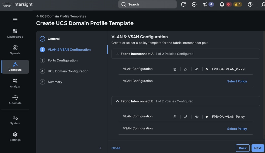
Procedure 18. Create a UCS Domain Profile Template: Ports Configuration for FI-A and FI-B
Note: Using separate port policies provides flexibility to configure ports (port numbers or speed) differently across the two FIs if required.
Step 1. For Ports Configuration, under Fabric Interconnect A, click Select Policy.
Step 2. In the Select Policy window, choose the previously created Port Policy for FI-A.
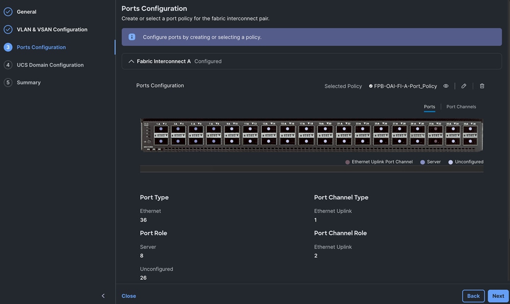
Step 3. For Ports Configuration, under Fabric Interconnect B, click Select Policy.
Step 4. In the Select Policy window, choose the previously created Port Policy for FI-B.
Step 5. Click Next.

Procedure 19. Create a UCS Domain Profile Template: UCS Domain Configuration
Step 1. For the UCS Domain Configuration, under Management, choose the previously configured policies for NTP, Syslog, Network Connectivity, SNMP, LDAP (not used in this CVD), Certificate Management (not used in this CVD) policies by clicking Select Policy for each policy.
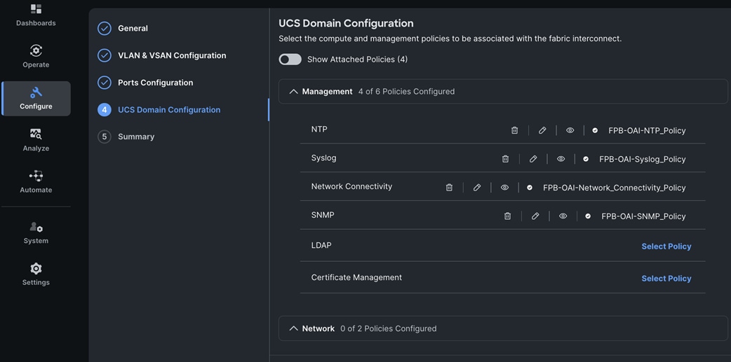
Step 2. Under Network, choose the previously configured policies for System QoS and System Control policies by clicking Select Policy for each policy.
Step 3. Click Next.
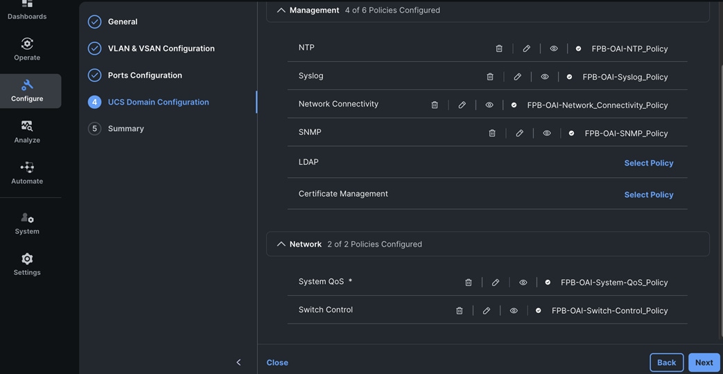
Procedure 20. Create a UCS Domain Profile Template : Summary
Step 1. In the Summary window, verify the settings across the Ports Configuration, VLAN & VSAN Configuration, and UCS Domain Configuration tabs.
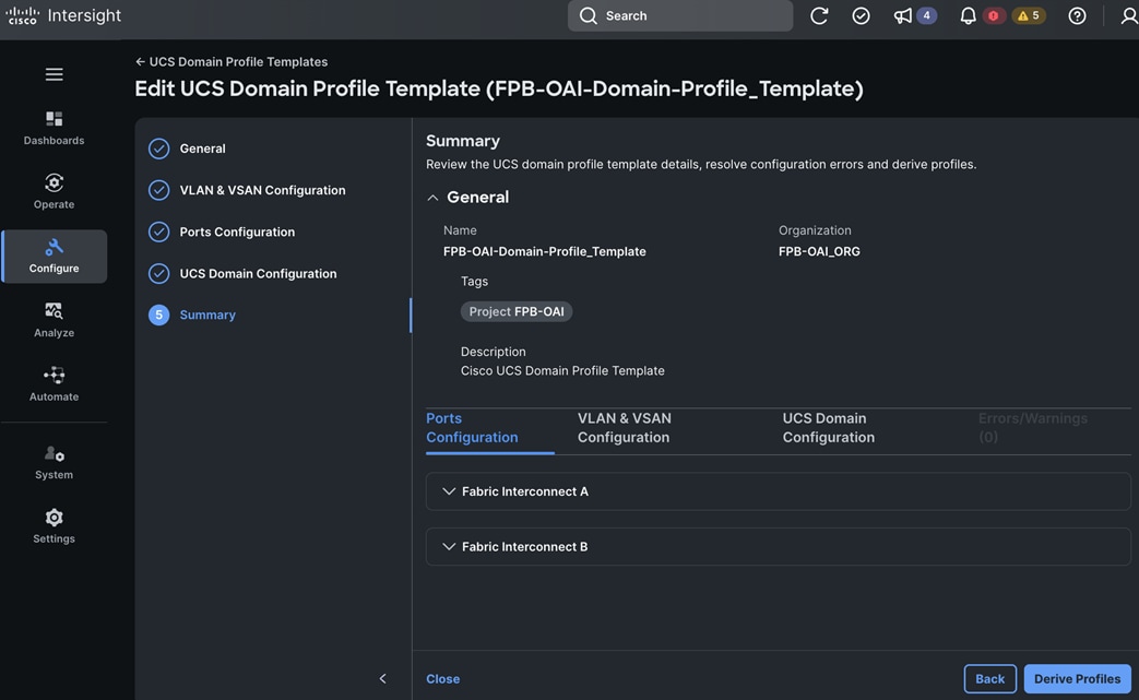
Step 2. Click Close to save the Domain Profile Template and derive the profiles later.
Procedure 21. Derive and Assign UCS Domain Profile Configuration for UCS domain
To generate a UCS domain Profile to configure the UCS domain, complete the following steps to derive a domain profile using the previously configured domain profile template.
Step 1. Use a web browser to navigate to intersight.com and log into your account.
Step 2. Go to Configure > Templates.
Step 3. Click UCS Domain Profile Templates.
Step 4. Choose a previously configured UCS Domain Profile Template from the list.
Step 5. Click the elipses and choose Derive Profiles from the drop-down list.
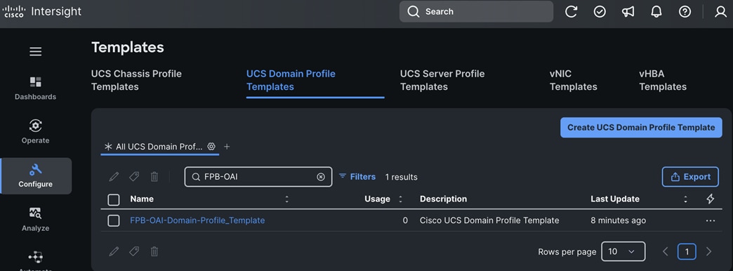
Step 6. From the Derive window, in the General section for Domain Assignment, choose Assign Now or Assign Later to deploy the UCS domain profile (now or later). For the former, choose the UCS domain from the list.
Step 7. Click Next.
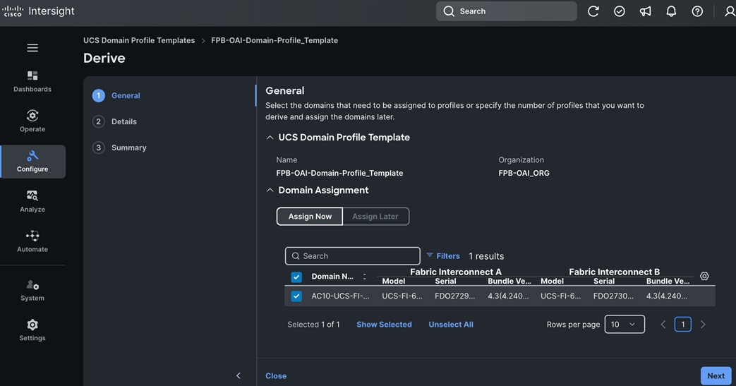
Step 8. From the Derive window, in the Details section, specify the profile names for the derived profile(s).
Step 9. Click Next.
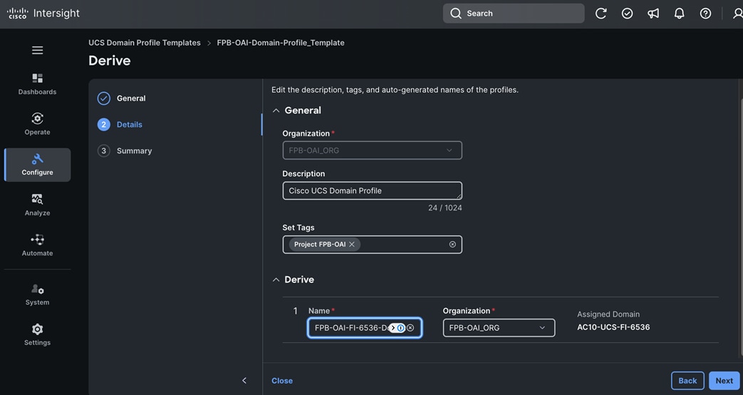
Step 10. From the Derive window, in the Summary section, verify the settings.
Step 11. Click Derive.
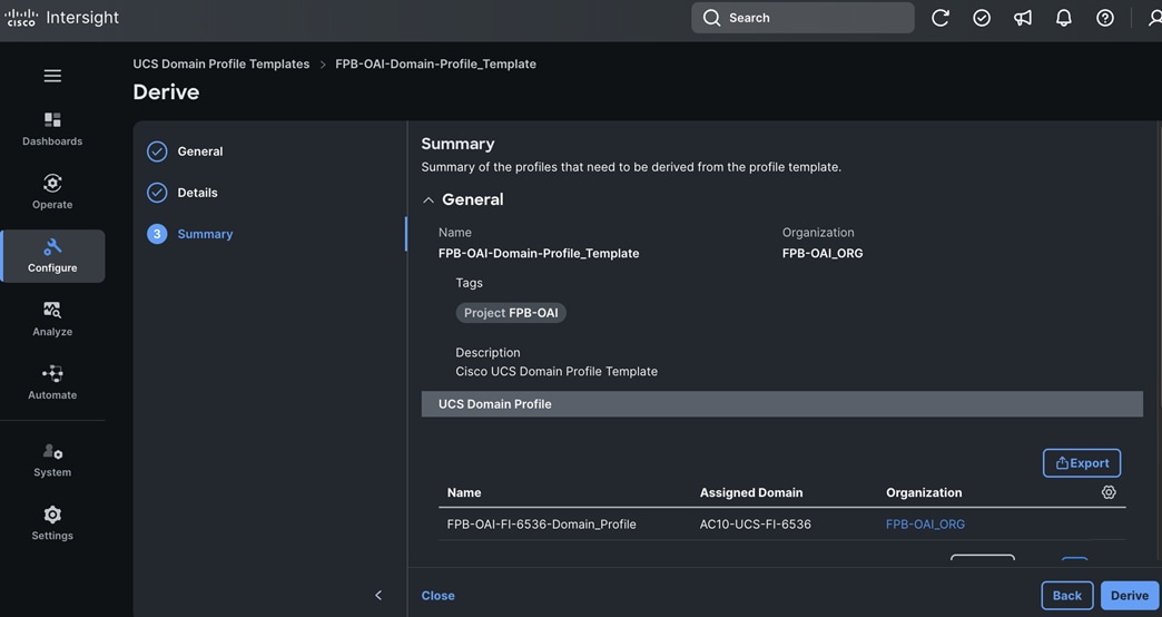
Procedure 22. Deploy the Cisco UCS Domain Profile to UCS Domain
Step 1. Use a web browser to navigate to intersight.com and log into your account.
Step 2. Go to Configure > Profiles.
Step 3. Click UCS Domain Profiles.
Step 4. Choose the previously derived UCS Domain Profile from the list. You can also create/derive new UCS Domain Profiles here.
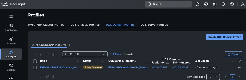
Step 5. Click the elipses and choose Deploy from the list.
Step 6. In the pop-up window, click Deploy.
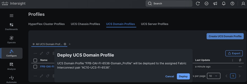
Step 7. For Name, specify a new name for the profile or us the previously specified one.
Step 8. (Optional) For Set Tags, specify value in key:value format.
Step 9. Click Next.
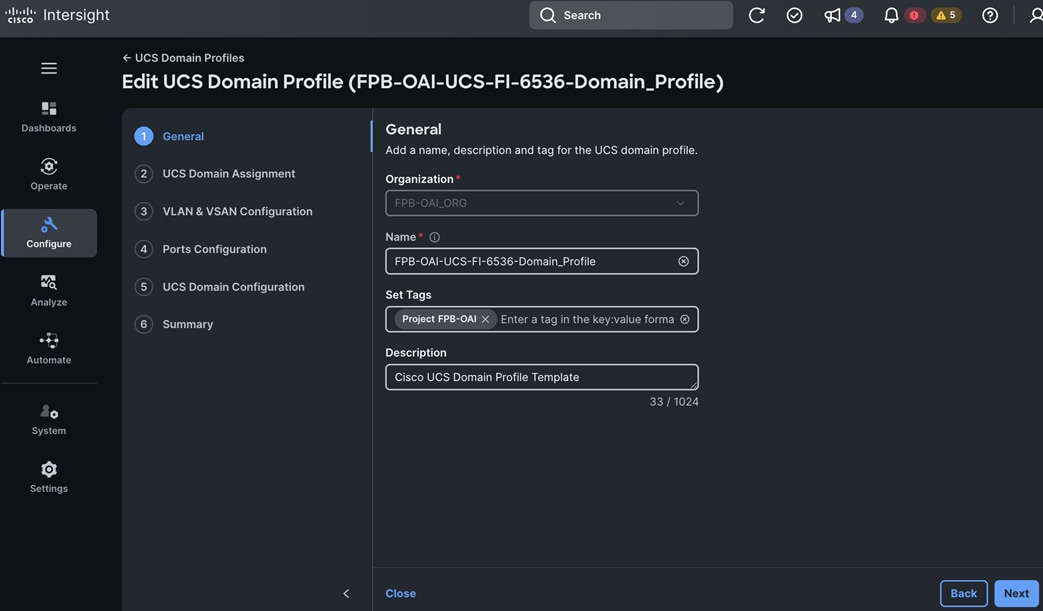
Step 10. For UCS Domain Assignment, choose the UCS FI to apply the configuration/profile.
Step 11. Click Next.
Step 12. Step through the remaining options (VLAN & VSAN Configuration, Ports Configuration, UCS Domain Configuration, and Summary) and verify the configuration.
Step 13. Click Deploy.
Note: The system will take some time to validate and configure the settings on the fabric interconnects.
Procedure 23. Verify the Cisco UCS Domain Profile Deployment
Note: It takes a while to discover the blades the first time. Watch the number of outstanding requests in Cisco Intersight. When the profile is successfully deployed, the Cisco UCS chassis and the blades should be successfully discovered.
Step 1. Go to Configure > Profiles > UCS Domain Profiles and verify that the domain profile was successfully deployed – it should have a status of OK.
Step 2. Go to Operate > Chassis to verify that the chassis has been discovered and is visible.
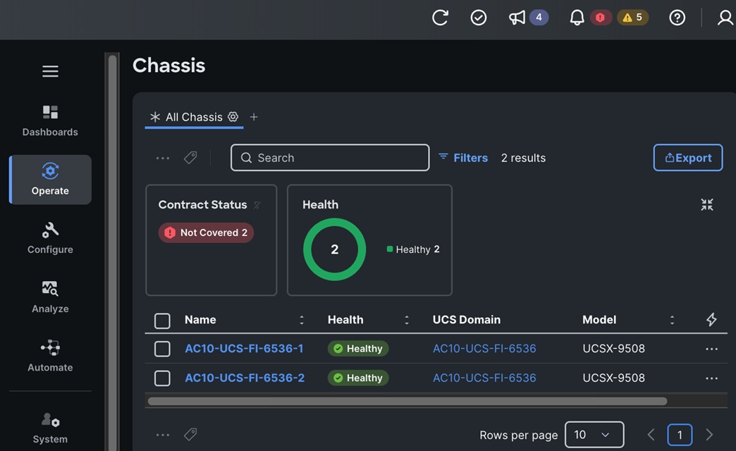
Step 3. Go to Operate > Servers to verify that the servers have been discovered and are healthy.
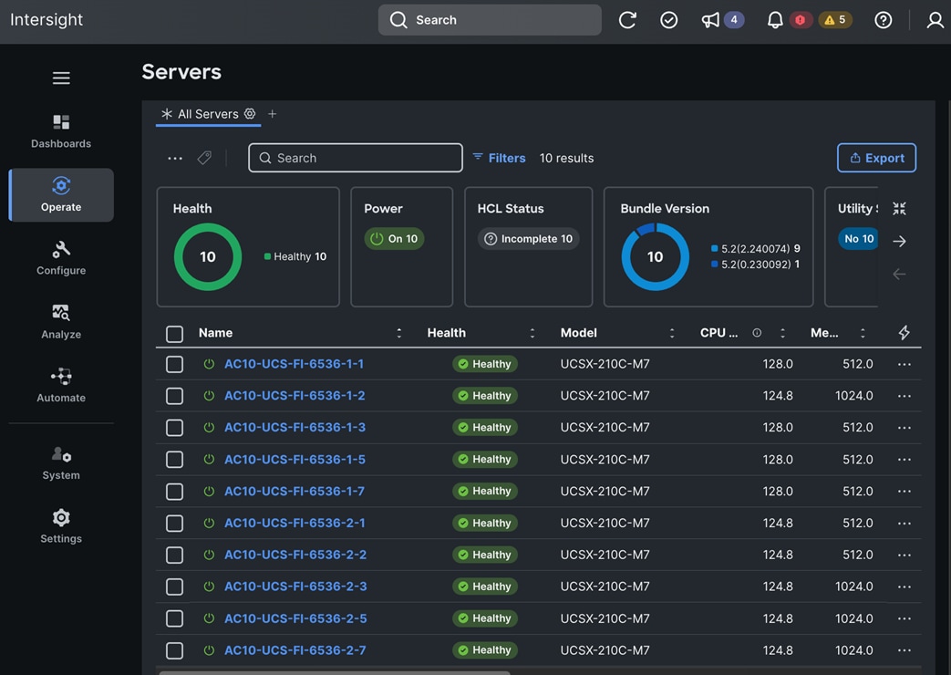
Configure the UCS Chassis using a Chassis Profile derived from a UCS Chassis Profile Template
Note: Chassis Profile Templates and Chassis Profiles only apply to Cisco UCS X-Series systems.
The procedures described in this section will create the pools and policies that are part of the UCS Chassis Profile Template. The template is then used to derive the UCS Chassis Profile for configuring a given Cisco UCS X-Series chassis. This includes:
● Create IP Pool for In-Band Management.
● Create IP Pool for Out-of-Band Management.
● Create IMC Access Policy: IP configuration for the in-band chassis connectivity. This setting is independent of Server IP connectivity and only applies to communication to and from the chassis.
● Create SNMP Policy to configure SNMP trap settings.
● Create Power Policy to enable power management and power supply redundancy mode.
● Create Thermal Policy to control the speed of FANs.
Note: The SNMP Policy can be configured as part of the UCS Domain Profile or through the Chassis Profile provisioned in this section.
These policies will be used to:
● Create a UCS Chassis Profile Template.
● Derive a UCS Chassis Profile from the UCS Domain Profile Template.
● Deploy the UCS Chassis Profile to provision a given UCS X-Series chassis.
Assumptions and Prerequisites
● Complete the initial setup of the Cisco UCS Fabric Interconnects with IP Management access.
● Valid cisco.com and Intersight accounts.
● Enable Cisco Smart Software Licensing on the Intersight account.
● Collect the setup information for your environment – see Table 12 for the required setup information.
Setup Information
Table 12. Cisco Intersight: UCS Chassis Profile Template
| Parameter Type |
Parameter Name | Value |
Additional Information |
| Organization |
FPB-OAI_ORG |
Specified earlier |
| Tags (Optional) |
Project: FPB-OAI |
|
| Description (Optional) |
<< specify for each pool and policy >> |
For example, UCS Chassis Policy |
| UCS Chassis Profile Template |
||
| In-Band Management IP Pool Name |
FPB-OAI-IB-MGMT-IP_Pool |
|
| Configure IPv4 Pool |
Enabled |
|
| Netmask |
255.255.255.0 |
|
| Gateway |
10.120.1.254 |
|
| Primary DNS |
10.120.1.240 |
|
| Secondary DNS |
172.20.10.53 |
|
| IP Blocks |
|
Can add multiple blocks |
| From |
10.120.1.128 |
IP address pool for Fabric Interconnects |
| Size |
2 |
|
| From |
10.120.1.121 |
IP address pool for servers connected to Fabric Interconnects |
| Size |
6 |
|
| Configure IPv6 Pool |
Disabled |
|
| Out-of-Band Management IP Pool Name |
FPB-OAI-OOB-MGMT-IP_Pool |
|
| Configure IPv4 Pool |
Enabled |
|
| Netmask |
255.255.255.0 |
|
| Gateway |
10.120.0.254 |
|
| Primary DNS |
172.20.4.53 |
|
| Secondary DNS |
172.20.4.54 |
|
| IP Blocks: |
|
Can add multiple blocks; IP address pool for servers connected to Fabric Interconnects |
| From |
10.120.0.231 |
|
| Size |
9 |
Range: 1-1024 |
| Configure IPv6 Pool |
Disabled |
|
| IMC Access Policy Name |
FPB-OAI-IMC-Access_Policy |
|
| In-Band Configuration |
Enabled |
|
| VLAN ID |
1201 |
|
| IPv4 Address Configuration |
Enabled |
|
| IPv6 Address Configuration |
Disabled |
|
| IP Pool |
FPB-OAI-IB-MGMT-IP_Pool |
|
| Out-of-Band Configuration |
Enabled |
|
| IP Pool |
FPB-OAI-OOB-MGMT-IP_Pool |
|
| Power Policy Name |
FPB-OAI-Power_Policy |
|
| Power Polling |
Enabled (Default) |
Supported only on UCS-X Series |
| Power Priority |
Low (Default) |
Options: Low, Medium, High. Determines the initial power allocation for servers. Supported only for Cisco UCS B-Series and X-Series servers. |
| Power Restore |
Last State |
Options: Last State, Always On, Always Off (Default). |
| Power Redundancy Mode |
Grid (Default) |
Options: Grid (Default), Not Redundant, N+1, N+2. Redundancy Mode determines the number of PSUs the chassis keeps as redundant. N+2 mode is only supported for Cisco UCS X series Chassis. |
| Processor Package Power Limit |
Default (Default) |
Options: Default, Maximum, Minimum. Processor Package Power Limit (PPL) of a server refers to the amount of power that a CPU can draw from the power supply. PPL feature is currently available exclusively on Cisco UCS C225/C245 M8 servers. |
| Power Save Mode |
Enabled (Default) |
If the requested power budget is less than the available power capacity, the additional PSUs not required to comply with redundancy policy are placed in power save mode. |
| Dynamic Power Balancing |
Enabled (Default) |
If enabled, this mode allows the chassis to dynamically reallocate the power between servers depending on their power usage. |
| Extended Power Capacity |
Enabled (Default) |
If Enabled, this mode allows chassis available power to be increased by borrowing power from redundant power supplies. This option is only supported for the Cisco UCS X-Series Chassis. |
| Power Allocation (Watts) |
0 (Default) |
Range: 0- 65535 |
| SNMP Policy Name |
FPB-OAI-SNMP_Policy |
See SNMP policy configuration in the policies created in the previous section for UCS Domain Profile Template |
| Thermal Policy Name |
FPB-OAI-Thermal_Policy |
|
| Fan Control Mode |
Balanced (Default) |
Options: Balanced (Default), Low Power, High Power, Maximum Power, Acoustic; the last 3 are applicable only to UCS X-Series and C-Series servers |
Deployment Steps
Use the setup information provided in this section to configure pools and policies for the Cisco UCS X-Series chassis. The pools and policies are part of the Cisco UCS Chassis Profile Template which is used to derive the UCS Chassis Profile to configure a given Cisco UCS X-Series chassis.
Note: The following procedures create IP Pools that are used by the IMC Access Policy in the Create UCS Chassis Profile Template.
Procedure 1. Create IP Pools – Out-of-Band Management
Step 1. Use a web browser to navigate to intersight.com and log into your account.
Step 2. Go to Configure > Pools.
Step 3. Click Create Pool.
Step 4. Choose IP.
Step 5. Click Start.
Step 6. From the Pools > IP Pool window, in the General section, for Organization, choose the previously created organization from the drop-down list.
Step 7. For Name, specify a name for this policy.
Step 8. (Optional) For Set Tags, specify value in key:value format.
Step 9. (Optional) For Description, specify a description for this policy.
Step 10. Click Next.
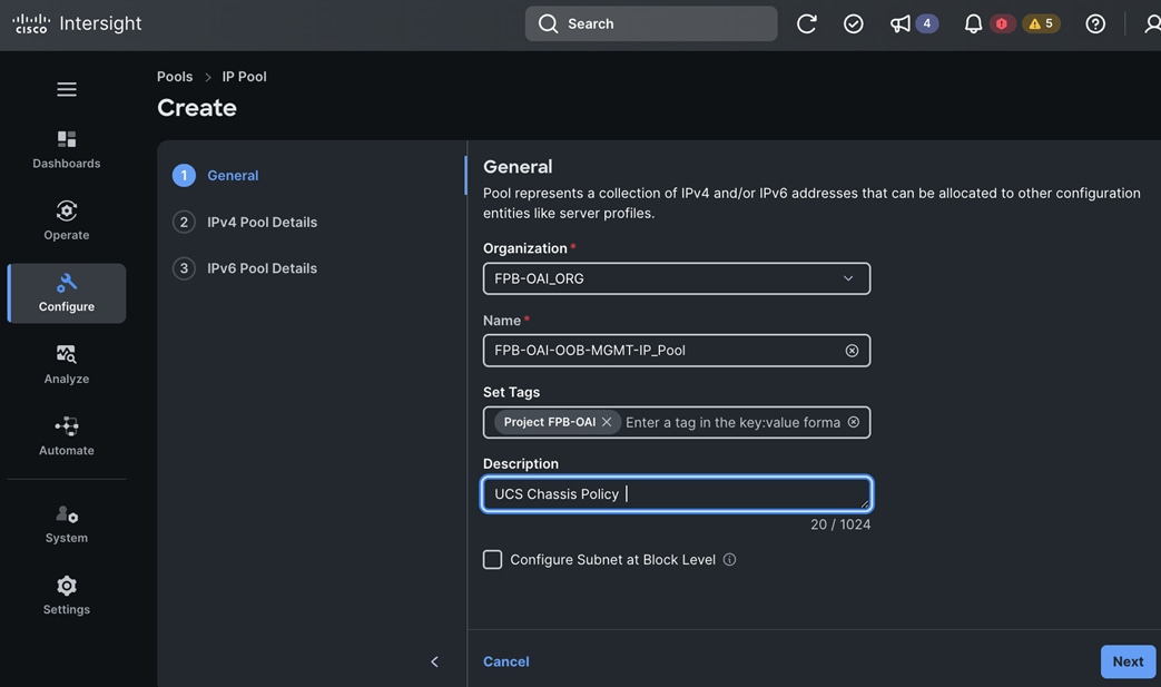
Step 11. In the IPv4 Pool Details section, specify the Netmask, Gateway, Primary DNS and Secondary DNS.
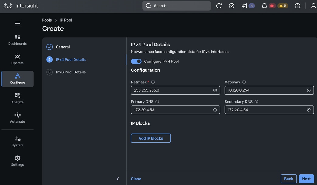
Step 12. Click Add IP Blocks.
Step 13. Click Next.
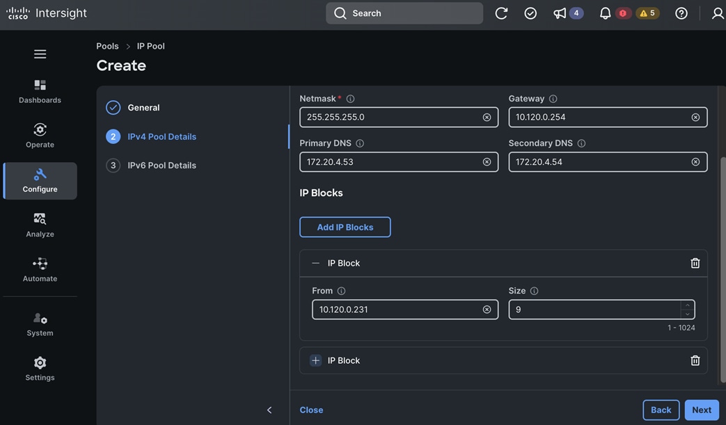
Step 14. Disable Configure IPv6 Pool.
Step 15. Click Create. A pop-up message displays stating the policy was created successfully.
Procedure 2. Create IP Pools – In-Band Management
Step 1. Use a web browser to navigate to intersight.com and log into your account.
Step 2. Go to Configure > Pools.
Step 3. Click Create Pool.
Step 4. Choose IP.
Step 5. Click Start.
Step 6. From the Pools > IP Pool window, in the General section, for Organization, choose the previously created organization from the drop-down list.
Step 7. For Name, specify a name for this policy.
Step 8. (Optional) For Set Tags, specify value in key:value format.
Step 9. (Optional) For Description, specify a description for this policy.
Step 10. Click Next.
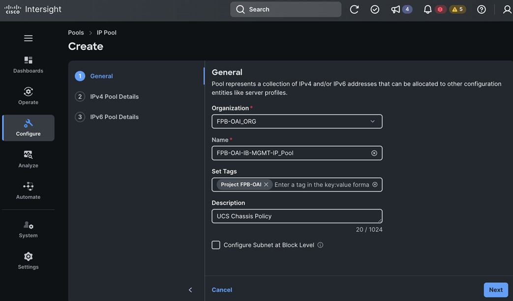
Step 11. In the IPv4 Pool Details section, specify the Netmask, Gateway, Primary DNS and Secondary DNS.
Step 12. Click Add IP Blocks. Add two IP blocks, one for UCS Fis and another for servers connected to the UCS FIs.
Step 13. Click Next.
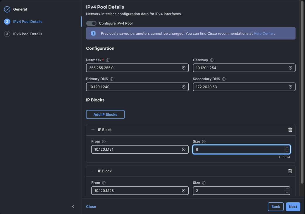
Step 14. Disable Configure IPv6 Pool.
Step 15. Click Create. A pop-up message displays stating the policy was created successfully.
Procedure 3. Create IMC Access Policy
Step 1. Use a web browser to navigate to intersight.com and log into your account.
Step 2. Go to Configure > Policies.
Step 3. Click Create Policy.
Step 4. Choose IMC Access.
Step 5. Click Start.
Step 6. From the Policies > IMC Access window, in the General section, for Organization, choose the previously created organization from the drop-down list.
Step 7. For Name, specify a name for this policy.
Step 8. (Optional) For Set Tags, specify value in key:value format.
Step 9. (Optional) For Description, specify a description for this policy.
Step 10. Click Next.
Step 11. In the Policy Details section, enable In-Band Configuration.
Step 12. For the VLAN ID, specify the ID for In-Band Management.
Step 13. Check the box for IPv4 Address Configuration.
Step 14. For IP Pool, click Select IP Pool to choose the previously configured In-Band Management IP Pool.
Step 15. Enable Out-of-Band Configuration.
Step 16. For IP Pool, click Select IP Pool to choose the previously configured Out-of-Band Management IP Pool.
Step 17. Click Next.
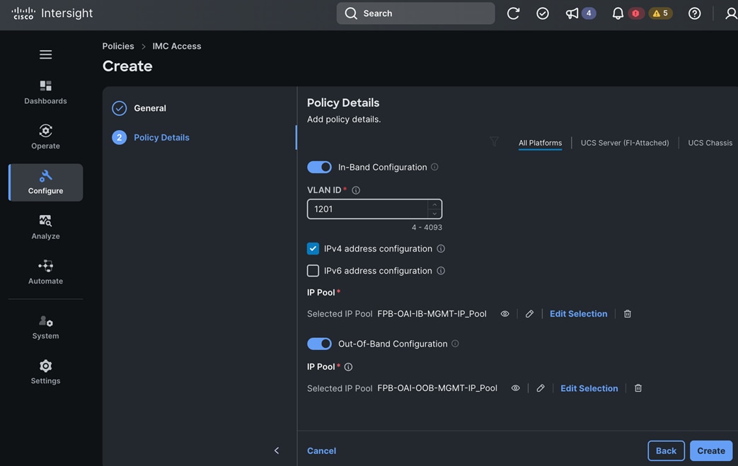
Step 18. Click Create. A pop-up message displays stating the policy was created successfully.
Procedure 4. Create a Power Policy
Step 1. Use a web browser to navigate to intersight.com and log into your account.
Step 2. Go to Configure > Policies.
Step 3. Click Create Policy.
Step 4. Choose Power.
Step 5. Click Start.
Step 6. From the Policies > Power window, in the General section, for Organization, choose the previously created organization from the drop-down list.
Step 7. For Name, specify a name for this policy.
Step 8. (Optional) For Set Tags, specify value in key:value format.
Step 9. (Optional) For Description, specify a description for this policy.
Step 10. Click Next.
Step 11. In the Policy Details section, for Power Restore state, use the drop-down list to change the state to Last State. Keep the remaining defaults.
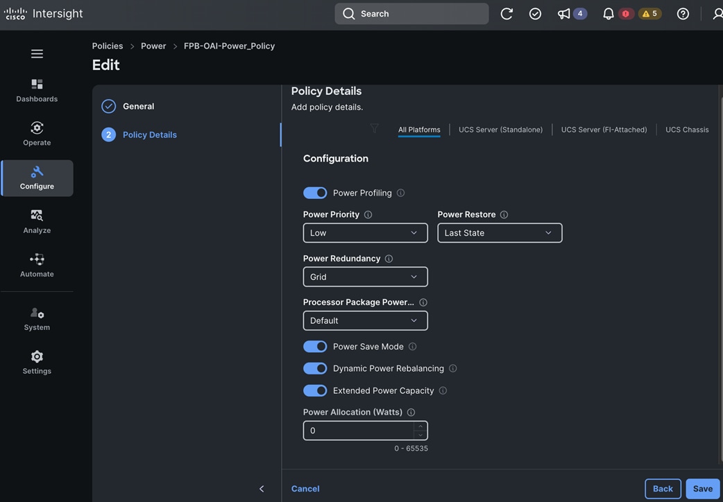
Step 12. Click Create. A pop-up message displays stating the policy was created successfully.
Procedure 5. Create a SNMP Policy
Note: This policy was already created in the UCS Domain Profile Template section of this document.
Procedure 6. Create a Thermal Policy
Step 1. Use a web browser to navigate to intersight.com and log into your account.
Step 2. Go to Configure > Policies.
Step 3. Click Create Policy.
Step 4. Choose Thermal.
Step 5. Click Start.
Step 6. In the Policies > Thermal window, in the General section, for Organization, choose the previously created organization from the drop-down list.
Step 7. For Name, specify a name for this policy.
Step 8. (Optional) For Set Tags, specify value in key:value format.
Step 9. (Optional) For Description, specify a description for this policy.
Step 10. Click Next.
Step 11. In the Policy Details section, use the defaults for FAN Control Mode.
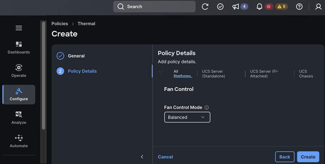
Step 12. Click Create. A pop-up message displays stating the policy was created successfully.
Note: The next set of procedures will create a Cisco UCS Chassis Profile Template using the pools and policies created in the previous procedures.
Procedure 7. Create a UCS Chassis Profile Template
Step 1. Use a web browser to navigate to intersight.com and log into your account.
Step 2. Go to Configure > Templates.
Step 3. Choose UCS Domain Profile Templates.
Step 4. Click Create UCS Domain Profile Template.
Step 5. In the Create UCS Domain Profile Template window, in the General section, for Organization, choose the previously created organization from the drop-down list.
Step 6. For Name, specify a name for this policy.
Step 7. (Optional) For Set Tags, specify value in key:value format.
Step 8. (Optional) For Description, specify a description for this policy.
Step 9. Click Next.
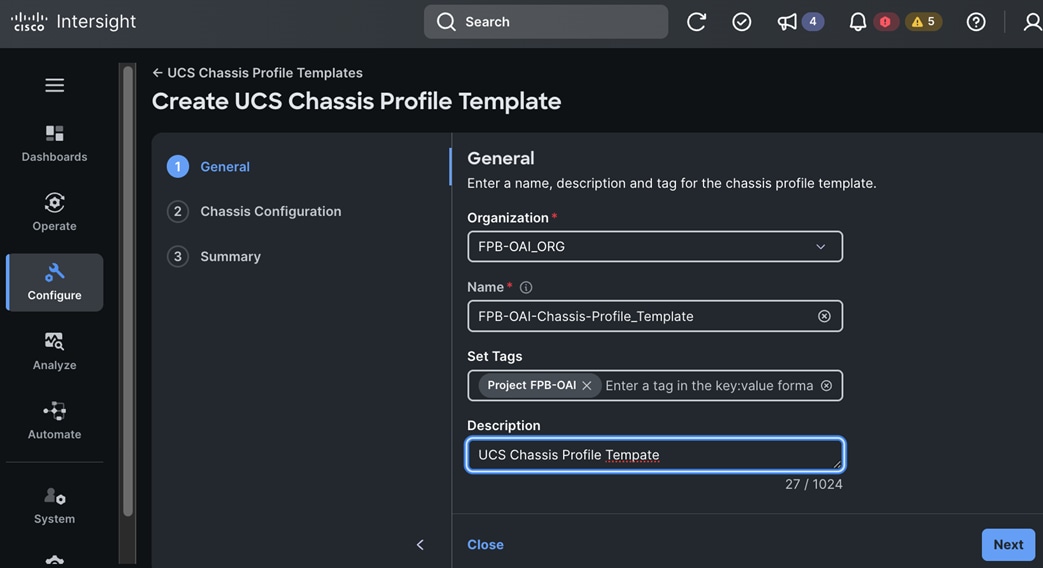
Step 10. In the Chassis Configuration section, for IMC Access, click Select Policy and choose the policy provisioned earlier.
Step 11. For Power policy, click Select Policy and choose the policy provisioned earlier.
Step 12. For SNMP policy, skip this step. This policy was already attached to Cisco UCS Domain Profile.
Step 13. For Thermal policy, click Select Policy and choose the policy provisioned earlier.
Step 14. Click Next.
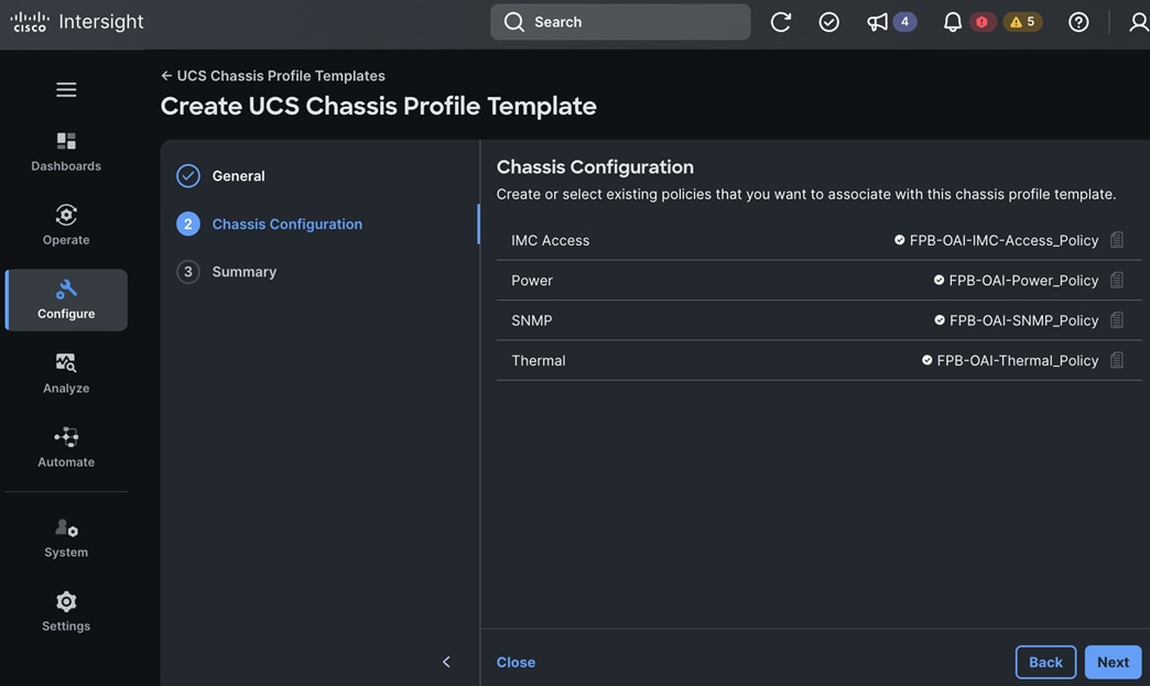
Step 15. In the Summary section, verify the settings.
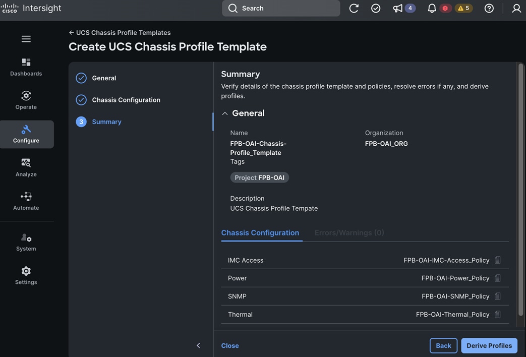
Step 16. Click Close to exit and save the chassis profile template. You can also click Derive Profiles to immediately derive a chassis profile.
Procedure 8. Derive UCS Chassis Profile(s) to configure UCS X-Series chassis
Step 1. Use a web browser to navigate to intersight.com and log into your account.
Step 2. Go to Configure > Templates.
Step 3. Choose UCS Chassis Profile Template.
Step 4. Click the UCS Chassis Profile Template to use from the list.
Step 5. Click the elispses and choose Derive Profiles from the drop-down list.
Step 6. Click Next.
Step 7. In the UCS Chassis Profile Template > FPB-OAI-Chassis-Profile_Template window, in the General section, choose Assign Later, and specify the Number of Profiles to derive.
Step 8. Click Next.
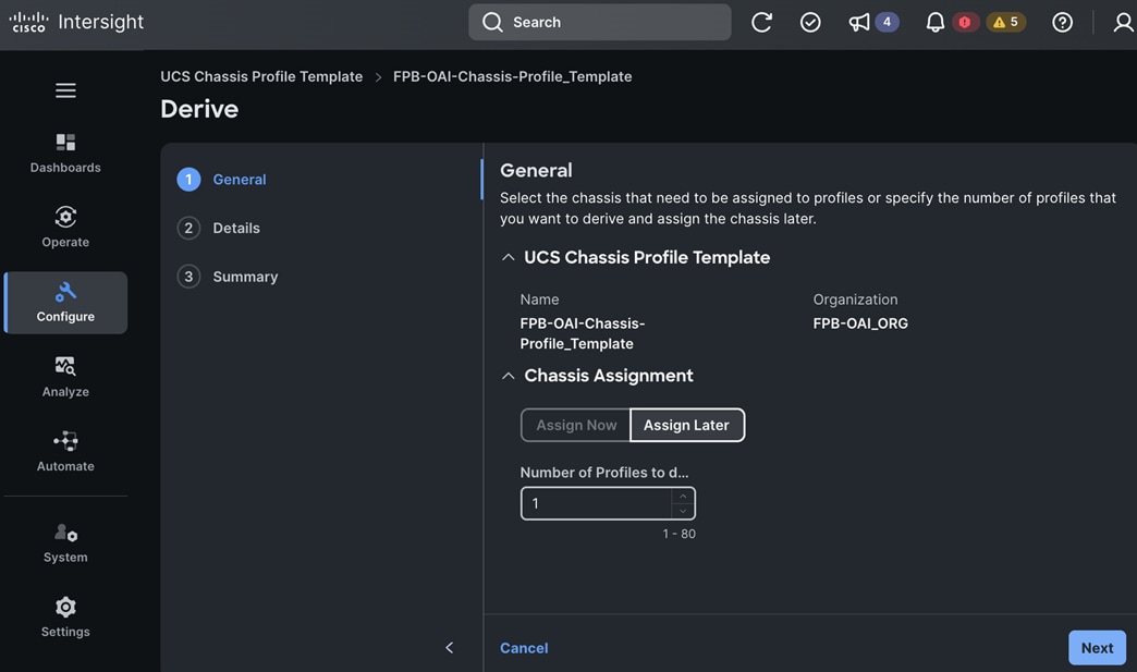
Step 9. In the Details section, specify the Name and Organization for the profile.
Step 10. Click Next.
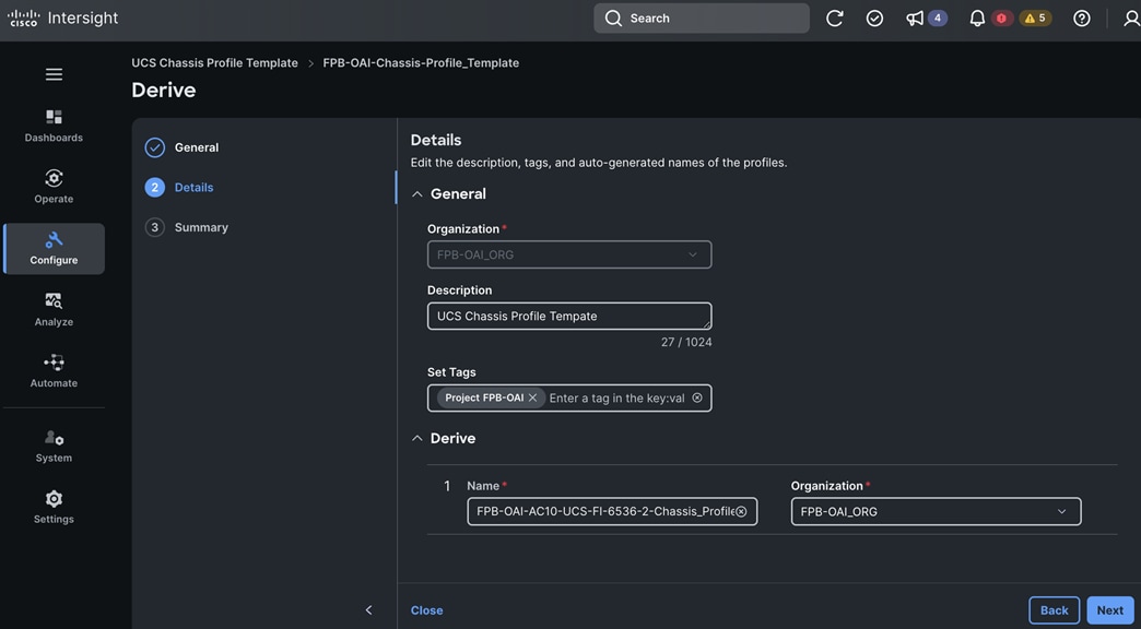
Step 11. In the Summary section, verify the information.
Step 12. Click Derive to derive a chassis profile to configure a given Cisco UCS X-Series chassis.
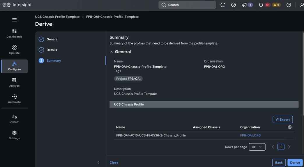
Procedure 9. Assign and Deploy Cisco UCS Chassis Profile to configure the Cisco UCS X-Series chassis
Step 1. Use a web browser to navigate to intersight.com and log into your account.
Step 2. Go to Configure > Profiles.
Step 3. Choose UCS Chassis Profiles.
Step 4. Choose the previously derived UCS Chassis Profile from the list. You can also create/derive a new UCS Chassis Profiles from here.
Step 5. Click the elipses and choose Edit from the drop-down list.
Step 6. Click the elipses and choose Deploy from the list.
Step 7. Choose the UCS X-Series chassis to deploy the profile.
Step 8. Click Next.
Step 9. Click Deploy.
Note: The system will take some time to validate and provision the settings on the selected Cisco UCS X-Series chassis.
Procedure 10. Verify Cisco UCS Chassis Profile Deployment
Step 1. Use a web browser to navigate to intersight.com and log into your account.
Step 2. Go to Configure > Profiles.
Step 3. Choose UCS Chassis Profiles.
Step 4. Verify that the chassis profile was successfully deployed – it should have a Status of OK with the profile Name and Chassis ID that was used to deploy the profile on the chassis.
Step 5. Verify that the chassis has been discovered and is visible under Operate > Chassis.
Configure the UCS Server(s) using the Server Profile(s) derived from a UCS Server Profile Template
The procedures described in this section create the pools and policies necessary to configure a UCS Server Profile Template.
● Pools
◦ UUID Pool
◦ iSCSI Pools
◦ IQN Pools (not used in this CVD)
◦ MAC Pool
◦ IP Pools (if different from ones created for UCS Chassis
◦ FC WW Pools (not used in this CVD)
● Policies
◦ Adapter Configuration Policy (Only for Standalone UCS Servers – not used in this CVD)
◦ BIOS Policy
◦ Boot Order Policy (Local boot used in this CVD)
◦ Ethernet Adapter Policy
◦ Ethernet Network Control Policy
◦ Ethernet Network Group (for vNICs/interfaces on servers) Policy
◦ Ethernet QoS Policy
◦ FC Adapter Policy (not used in this CVD)
◦ FC NVMe Initiator Adapter Policy (not used in this CVD)
◦ FC Network Policy (not used in this CVD)
◦ FC QoS Policy (not used in this CVD)
◦ Firmware Policy
◦ IPMI over LAN Policy
◦ iSCSI Adapter Policy (not used in this CVD)
◦ iSCSI Boot Policy (not used in this CVD)
◦ iSCSI Target Policy (not used in this CVD)
◦ Local User Policy
◦ SAN Connectivity Policy (not used in this CVD)
◦ Storage Policy
◦ vKVM Policy
◦ vMedia Policy
Some of the pools and policies defined above are used to create vNIC Templates and LAN Connectivity Policies as summarized below:
● vNIC Templates for OpenShift Control Nodes
● vNIC Templates for OpenShift Worker Nodes (with storage NICs for storage access)
● LAN Connectivity Policies for:
◦ FC Boot (not used in this CVD)
◦ ISCSI Boot (not used in this CVD)
◦ OpenShift Control Nodes using Local Boot
◦ OpenShift Worker Nodes using Local Boot (+ iSCSI/NVMe Storage, + NFS/Object Storage)
Note: vNIC Templates are used to derive vNICs for LAN Connectivity Policies used by Server Profile Templates.
These pools and policies are used for the following:
● Create UCS Server Profile Templates for OpenShift Control and Worker Nodes
● Derive UCS Server Profiles from UCS Server Profile Templates for OpenShift Control and Worker Nodes
● Deploy the UCS Server Profiles to provision UCS servers as OpenShift Control and Worker Nodes
Assumptions and Prerequisites
● Complete the initial setup of Cisco UCS Fabric Interconnects with IP Management access
● Valid cisco.com and Intersight accounts
● Enable Cisco Smart Software Licensing on the Intersight account
● Name of the Intersight Organization of which the UCS Server is comprised
● Collect setup information for your environment - see Table 13 for the required setup information
Table 13. Cisco Intersight: UCS Server Profile Template
| Variable/Infor |
Variable Name |
Value |
Additional Information |
| Intersight URL |
|
https://intersight.com |
|
| Intersight Account Name |
|
<specify> |
For this CVD: RTP-B4-AC10-FlexPod |
| Organization Name |
|
FPB-OAI_ORG |
Organization |
| Resource Group Name |
|
FPB-OAI_RG |
Resource Group |
| Tags (Optional) |
|
Project: FPB-OAI |
Use for all pools, policies, and templates |
| Description (Optional) |
|
<< specify for each pool and policy >> |
Use for all pools, policies, and templates |
| Used to generate default configurations with Automation |
|||
| Project Prefix |
|
FPB-OAI |
Uses as prefix for pool and policy names |
| Project Sub-Prefix |
|
OCP |
|
| Server CPU Type |
|
Intel |
Options: Intel | AMD (used to generate default policy names and policies) |
| Server CPU Model |
|
M7 |
Options: For Intel (M5, M6, M7) |
| Server VIC Type |
|
5G |
Options: 4th Gen (for example, UCSX-v4-Q25GML) or 5th Gen |
| Server Boot Method |
|
LB (Local Boot) |
Options: LB | iSCSI | FC |
| Cisco UCS Server Profile Template: Pools |
|||
| UUID Pool Name |
|
FPB-OAI-UUID_Pool |
|
| UUID Prefix |
|
AC100000-0000-1001 |
|
| UUID Block |
|
AC10-000000001111 |
|
| UUID Block Size |
|
50 |
|
| MAC Pool Name |
|
FPB-OAI-Fabric-A-MAC_Pool |
|
| Description |
|
<specify> |
For example, UCS Server Profile Template: MAC Pool for FI-A |
| Starting MAC Address |
|
00:B4:AC:10:0A:50 |
UCS Pools typically start with 00:B5: |
| Pool Size |
|
64 |
|
| MAC Pool Name |
|
FPB-OAI-Fabric-B-MAC_Pool |
|
| Description |
|
<specify> |
For example, UCS Server Profile Template: MAC Pool for FI-B |
| Starting MAC Address |
|
00:B4:AC:10:0B:50 |
|
| Pool Size |
|
64 |
|
| IP Pool |
|
|
Provisioned earlier (Chassis Policy) |
| Cisco UCS Server Profile Template: Policies |
|||
| Adapter Configuration Policy |
|
N/A |
|
| BIOS Policy Name |
|
FPB-OAI-Intel-M7-BIOS_Policy |
|
| Description |
|
<specify> |
For example, UCS Server Profile Template: BIOS Policy |
| Processor Configuration |
|
|
|
|
|
Processor C6 Report |
Enabled |
|
|
|
Workload Configuration |
Balanced |
|
|
|
Intel Virtualization Technology (Intel ® VT) |
Disabled |
|
| Server Management |
|
|
|
|
|
Consistent Device Naming |
Enabled |
|
| Boot Order Policy Name |
|
FPB-OAI-LB-5G-Boot-Order_Policy |
Local boot used in this CVD |
| Description |
|
<specify> |
For example, UCS Server Profile Template: Boot Order Policy |
| Boot Mode |
|
Unified Extensible Firmware Interface (UEFI) |
Options: UEFI (Default) or Legacy |
| Enable Secure Boot |
|
Disabled (Default) |
Must be disabled for NVIDIA GPUs |
| Add Boot Device |
|
|
|
| Boot Device 1 |
Virtual Media |
Enabled |
|
|
|
Device Name |
KVM-Mapped-ISO |
|
|
|
Sub-Type |
KVM MAPPED DVD |
|
| Boot Device 2 |
Virtual Media |
Disabled |
|
|
|
Device Name |
CIMC-Mapped-ISO |
|
|
|
Sub-Type |
CIMC MAPPED DVD |
|
| Boot Device 3 |
Local Disk |
Enabled |
|
|
|
Device Name |
M2-Boot |
|
|
|
Slot |
MSTOR-RAID |
|
|
|
Bootloader Name |
<specify as needed> |
Optional |
|
|
Bootloader Description |
<specify as needed> |
Optional |
|
|
Bootloader Path |
<specify as needed> |
Optional |
| Ethernet Adapter Policy Name |
|
FPB-OAI-Linux-Default-Ethernet-Adapter_Policy |
|
| Description |
|
<specify> |
For example, UCS Server Profile Template: Linux Default Ethernet Adapter Policy |
| Policy Details |
|
Linux-v2 |
Cisco provided Ethernet Adapter policy |
| Ethernet Adapter Policy Name |
|
FPB-OAI-Linux-RX16Q5G-Adapter_Policy |
|
| Description |
|
<specify> |
For example, UCS Server Profile Template: Linux 16 RX Queue Ethernet Adapter Policy |
| Policy Details |
|
Interrupt Settings
● Interrupts: 19
● Interrupt Mode: MSIx
● Interrupt Timer: 125us
● Interrupt Coalescing Type: Min
Receive
● Receive Queue Count: 16
● Receive Ring Size: 16384
Transmit
● Transmit Queue Count: 1
● Transmit Ring Size: 16384
Completion
● Completion Queue Count: 17
● Completion Ring Size: 1
● Uplink Failback Timeout: 5
TCP Offload Settings – Enabled Receive Side Scaling
● Enable Receive Side Scaling
● Enable IPv4 Hash
● Enable TCP and IPv4 Hash
● Enable IPv6 Hash
● Enable TCP and IPv6 Hash
|
|
| Ethernet Network Control Policy Name |
|
FPB-OAI-Ethernet-Network-Control_Policy |
|
| Description |
|
<specify> |
For example, UCS Server Profile Template: Ethernet Network Control Policy |
| Enable CDP |
|
Enabled |
|
| LLDP - Enable Transmit |
|
Enabled |
|
| LLDP - Enable Receive |
|
Enabled |
|
| Ethernet Network Group (ENG) Policy Name |
|
FPB-OAI-IB-MGMT-ENG_Policy |
For vNICs/interfaces on servers |
| Description |
description_of_ib_mgmt_eng_policy |
<specify> |
Ethernet Network Group(ENG) Policy for In-Band Management vNIC |
| Native VLAN |
|
1201 |
|
| Allowed VLANs |
|
1201 |
|
| Ethernet Network Group (ENG) Policy Name |
|
FPB-OAI-CLUSTER-MGMT-ENG_Policy |
|
| Description |
description_of_cluster_mgmt_eng_policy |
<specify> |
Ethernet Network Group(ENG) Policy for OpenShift Cluster Management vNIC |
| Native VLAN |
|
1202 |
|
| Allowed VLANs |
|
1202 |
|
| Ethernet Network Group (ENG) Policy Name |
|
FPB-OAI-OBJ-STORE-ENG_Policy |
|
| Description |
description_of_obj_store_eng_policy |
<specify> |
Ethernet Network Group(ENG) Policy for Object Store vNIC |
| Native VLAN |
|
1209 |
|
| Allowed VLANs |
|
1209 |
|
| Ethernet Network Group (ENG) Policy Name |
|
FPB-OAI-iSCSI-A-ENG_Policy |
|
| Description |
description_of_iscsi_a_eng_policy |
<specify> |
Ethernet Network Group(ENG) Policy for iSCSI-A vNIC |
| Native VLAN |
|
3015 |
|
| Allowed VLANs |
|
3015 |
|
| Ethernet Network Group (ENG) Policy Name |
|
FPB-OAI-iSCSI-B-ENG_Policy |
|
| Description |
description_of_iscsi_b_eng_policy |
<specify> |
Ethernet Network Group(ENG) Policy for iSCSI-B vNIC |
| Native VLAN |
|
3025 |
|
| Allowed VLANs |
|
3025 |
|
| Ethernet Network Group (ENG) Policy Name |
|
FPB-OAI-NFS-ENG_Policy |
|
| Description |
description_of_nfs_eng_policy |
<specify> |
Ethernet Network Group(ENG) Policy for NFS vNIC |
| Native VLAN |
|
3055 |
|
| Allowed VLANs |
|
3055 |
|
| Ethernet QoS Policy Name |
|
FPB-OAI-Default-Ethernet-QoS_Policy |
|
| Description |
description_of_default_ethernet_qos_policy |
<specify> |
UCS Server Profile Template: Default QoS Policy |
| MTU |
default_mtu |
1500 |
|
| Rate-Limit |
default_rate_limit |
0 |
|
| Class of Service |
default_class_of_service |
0 |
|
| Burst |
default_burst |
10240 |
|
| Priority |
default_priority |
Best Effort |
|
| Rate-Limit |
default_rate_limit |
0 |
|
| Ethernet QoS Policy Name |
|
FPB-OAI-Jumbo-Ethernet-QoS_Policy |
|
| Description |
description_of_jumbo_ethernet_qos_policy |
<specify> |
UCS Server Profile Template: Jumbo QoS Policy |
| MTU |
jumbo_mtu |
9000 |
|
| Rate-Limit |
jumbo_rate_limit |
0 |
|
| Class of Service |
jumbo_class_of_service |
0 |
|
| Burst |
jumbo_burst |
10240 |
|
| Priority |
jumbo_priority |
Best Effort |
|
| FC Adapter Policy |
N/A |
|
|
| FC NVMe Initiator Adapter Policy |
N/A |
|
|
| FC Network Policy |
N/A |
|
|
| FC QoS Policy |
N/A |
|
|
| Firmware Policy Name |
|
FPB-OAI-Intel-M7-Firmware_Policy |
|
| Target Platform |
|
UCS Server (FI-Attached) |
Other Options: UCS Server (Standalone) |
| Description |
|
<specify> |
UCS Server Profile Template: Firmware Policy |
| Model Family |
|
UCSX-210-M7 |
|
| Bundle Version |
|
<specify> |
|
| IPMI over LAN Policy Name |
|
FPB-OAI-IPMI-LAN_Policy |
|
| Description |
|
<specify> |
UCS Server Profile Template: IPMI over LAN Policy |
| Enable IPMI over LAN |
|
Enabled |
|
| Privilege Level |
|
admin |
|
| iSCSI Adapter Policy |
N/A |
|
|
| iSCSI Boot Policy |
N/A |
|
|
| iSCSI Target Policy |
N/A |
|
|
| LAN Connectivity Policy for FC Boot |
N/A |
|
|
| LAN Connectivity Policy for ISCSI Boot |
N/A |
|
|
| LAN Connectivity Policy for Local Boot |
|
|
|
| Local User Policy Name |
|
FPB-OAI-Local-User_Policy |
|
| Enforce Strong Password |
|
Enabled |
|
| Add New User |
|
|
|
|
|
Username |
<specify username> |
(Example: ac10-admin) |
|
|
Role |
admin |
|
|
|
Password |
<specify password> |
|
| SAN Connectivity Policy |
N/A |
|
|
| Storage Policy Name |
|
FPB-OAI-Storage_Policy |
|
| Description |
|
<specify> |
UCS Server Profile Template: Storage Policy |
| M2VirtualDrive |
|
|
|
| Enable |
|
True |
|
| Controller Slot |
|
MSTOR-RAID-1 |
|
| Name |
|
MStorBootVd |
|
| vKVM Policy Name |
|
FPB-OAI-vKVM_Policy |
|
| Description |
|
<specify> |
UCS Server Profile Template: vKVM Policy to enable Tunneled KVM |
| Enable Virtual KVM |
|
Enabled |
Max Sessions = 4 (Default) |
| Enable Video Encryption |
|
Enabled |
|
| Allow Tunneled vKVM |
|
Enabled |
|
| vMedia Policy Name |
|
FPB-OAI-vMedia_Policy |
|
| Description |
|
<specify> |
UCS Server Profile Template: vMedia Policy to mount ISOs |
| Enable Virtual Media |
|
Enabled |
|
| Enable Virtual Media Encryption |
|
Enabled |
|
| Enable Low Power USB |
|
Enabled |
|
| (Optional) Add Virtual Media |
|||
| Media Type |
|
CDD |
|
| Protocol |
|
HTTP/HTTPS |
(Other options: NFS, CIFS) |
| Volume |
|
HTTP-ISO |
|
| File Location |
|
10.120.1.225 |
|
| Remote Path |
|
http://10.120.1.225/iso/ discovery_image_ac10-ocp.iso |
|
| Username |
|
<specify> |
|
| Password |
|
<specify> |
|
| Management Configuration |
|||
| (Optional) Certificate Management Policy |
Specified earlier – part of UCS Domain policy |
||
| IMC Access Policy |
Specified earlier – part of UCS Domain policy |
||
| Network Configuration |
|||
| vNIC Templates – OpenShift Control Nodes |
|||
| vNIC-1 |
|
|
|
| Name |
|
FPB-OAI-C-IB-MGMT-vNIC_Template |
Also for OCP Power Management/BMC/Provisioning network |
| Description |
|
<specify> |
In-Band Management vNIC Template |
| Allow Override |
|
Disabled |
|
| Mac Pool |
|
FPB-OAI-Fabric-A-MAC_Pool |
|
| Placement Switch ID |
|
A |
|
| Consistent Device Naming (CDN) Source |
|
vNIC Name |
|
| Failover |
|
Enabled |
Fabric/FI Failover |
| Ethernet Network Group |
|
FPB-OAI-IB-MGMT-ENG_Policy |
|
| Ethernet Network Control |
|
FPB-OAI-Ethernet-Network-Control_Policy |
|
| Ethernet QoS |
|
FPB-OAI-Default-Ethernet-QoS_Policy |
|
| Ethernet Adapter |
|
FPB-OAI-Linux-Default-Ethernet-Adapter_Policy |
|
| vNIC-2 |
|
|
|
| Name |
|
FPB-OAI-C-CL-MGMT-vNIC_Template |
Cluster Management vNIC Template for OpenShift Machine and Pod Networks. Same as OpenShift Baremetal network |
| Description |
|
<specify> |
OpenShift Cluster Management vNIC Template |
| Allow Override |
|
Disabled |
|
| Mac Pool |
|
FPB-OAI-Fabric-A-MAC_Pool |
|
| Placement Switch ID |
|
A |
|
| Consistent Device Naming (CDN) Source |
|
vNIC Name |
|
| Failover |
|
Enabled |
Fabric/FI Failover |
| Ethernet Network Group Policy |
|
FPB-OAI-CL-MGMT-ENG_Policy |
|
| Ethernet Network Control Policy |
|
FPB-OAI-Ethernet-Network-Control_Policy |
|
| Ethernet QoS Policy |
|
FPB-OAI-Default-Ethernet-QoS_Policy |
|
| Ethernet Adapter Policy |
|
FPB-OAI-Linux-Default-Ethernet-Adapter_Policy |
|
| vNIC Templates – OpenShift Worker Nodes |
|||
| vNIC-1 |
|
|
|
| Name |
|
FPB-OAI-W-IB-MGMT-vNIC_Template |
Also for OCP Power Management/BMC/Provisioning network |
| Description |
|
<specify> |
In-Band Management vNIC Template |
| Allow Override |
|
Disabled |
|
| Mac Pool |
|
FPB-OAI-Fabric-A-MAC_Pool |
|
| Placement Switch ID |
|
A |
|
| Consistent Device Naming (CDN) Source |
|
vNIC Name |
|
| Failover |
|
Enabled |
Fabric/FI Failover |
| Fabric Ethernet Network Group Policy |
|
FPB-OAI-IB-MGMT-ENG_Policy |
|
| Fabric Ethernet Network Control Policy |
|
FPB-OAI-Ethernet-Network-Control_Policy |
|
| Ethernet QoS Policy |
|
FPB-OAI-Default-Ethernet-QoS_Policy |
|
| Ethernet Adapter Policy |
|
FPB-OAI-Linux-Default-Ethernet-Adapter_Policy |
|
| vNIC-2 |
|
|
|
| Name |
|
FPB-OAI-W-CL-MGMT-vNIC_Template |
Cluster Management vNIC Template for OpenShift Machine and Pod Networks. Same as OpenShift Baremetal network |
| Description |
|
<specify> |
OpenShift Cluster Management vNIC Template |
| Allow Override |
|
Disabled |
|
| Mac Pool |
|
FPB-OAI-Fabric-A-MAC_Pool |
|
| Placement Switch ID |
|
A |
|
| Consistent Device Naming (CDN) Source |
|
vNIC Name |
|
| Failover |
|
Enabled |
Fabric/FI Failover |
| Fabric Ethernet Network Group Policy |
|
FPB-OAI-CL-MGMT-ENG_Policy |
|
| Fabric Ethernet Network Control Policy |
|
FPB-OAI-Ethernet-Network-Control_Policy |
|
| Ethernet QoS Policy |
|
FPB-OAI-Default-Ethernet-QoS_Policy |
|
| Ethernet Adapter Policy |
|
FPB-OAI-Linux-Default-Ethernet-Adapter_Policy |
|
| vNIC-3 |
|
|
|
| Name |
|
FPB-OAI-W-iSCSI-A-vNIC_Template |
|
| Description |
|
<specify> |
iSCSI-A/NVMe-TCP-A vNIC Template |
| Allow Override |
|
Disabled |
|
| Mac Pool |
|
FPB-OAI-Fabric-A-MAC_Pool |
|
| Placement Switch ID |
|
A |
|
| Consistent Device Naming (CDN) Source |
|
vNIC Name |
|
| Failover |
|
Disabled |
Fabric/FI Failover |
| Fabric Ethernet Network Group Policy |
|
FPB-OAI-iSCSI-A-ENG_Policy |
|
| Fabric Ethernet Network Control Policy |
|
FPB-OAI-Ethernet-Network-Control_Policy |
|
| Ethernet QoS Policy |
|
FPB-OAI-Jumbo-Ethernet-QoS_Policy |
|
| Ethernet Adapter Policy |
|
FPB-OAI-Linux-RX16Q5G-Ethernet-Adapter_Policy |
|
| vNIC-4 |
|
|
|
| Name |
|
FPB-OAI-W-iSCSI-B-vNIC_Template |
|
| Description |
|
<specify> |
iSCSI-B/NVMe-TCP-B vNIC Template |
| Allow Override |
|
Disabled |
|
| Mac Pool |
|
FPB-OAI-Fabric-B-MAC_Pool |
|
| Placement Switch ID |
|
B |
|
| Consistent Device Naming (CDN) Source |
|
vNIC Name |
|
| Failover |
|
Disabled |
Fabric/FI Failover |
| Fabric Ethernet Network Group Policy |
|
FPB-OAI-iSCSI-B-ENG_Policy |
|
| Fabric Ethernet Network Control Policy |
|
FPB-OAI-Ethernet-Network-Control_Policy |
|
| Ethernet QoS Policy |
|
FPB-OAI-Jumbo-Ethernet-QoS_Policy |
|
| Ethernet Adapter Policy |
|
FPB-OAI-Linux-RX16Q5G-Ethernet-Adapter_Policy |
|
| vNIC-5 |
|
|
|
| Name |
|
FPB-OAI-W-NFS-vNIC_Template |
|
| Description |
|
<specify> |
NFS vNIC Template |
| Allow Override |
|
Disabled |
|
| Mac Pool |
|
FPB-OAI-Fabric-A-MAC_Pool |
|
| Placement Switch ID |
|
A |
|
| Consistent Device Naming (CDN) Source |
|
vNIC Name |
|
| Failover |
|
Enabled |
Fabric/FI Failover |
| Fabric Ethernet Network Group Policy |
|
FPB-OAI-NFS-ENG_Policy |
|
| Fabric Ethernet Network Control Policy |
|
FPB-OAI-Ethernet-Network-Control_Policy |
|
| Ethernet QoS Policy |
|
FPB-OAI-Jumbo-Ethernet-QoS_Policy |
|
| Ethernet Adapter Policy |
|
FPB-OAI-Linux-RX16Q5G-Ethernet-Adapter_Policy |
|
| vNIC-6 |
|
|
|
| Name |
|
FPB-OAI-W-OBJ-vNIC_Template |
|
| Description |
|
<specify> |
Object Store vNIC Template |
| Allow Override |
|
Disabled |
|
| Mac Pool |
|
FPB-OAI-Fabric-B-MAC_Pool |
|
| Placement Switch ID |
|
B |
|
| Consistent Device Naming (CDN) Source |
|
vNIC Name |
|
| Failover |
|
Enabled |
Fabric/FI Failover |
| Fabric Ethernet Network Group Policy |
|
FPB-OAI-OBJ-STORE-ENG_Policy |
|
| Fabric Ethernet Network Control Policy |
|
FPB-OAI-Ethernet-Network-Control_Policy |
|
| Ethernet QoS Policy |
|
FPB-OAI-Jumbo-Ethernet-QoS_Policy |
|
| Ethernet Adapter Policy |
|
FPB-OAI-Linux-RX16Q5G-Ethernet-Adapter_Policy |
|
| LAN Connectivity Policy – OpenShift Control Nodes Project: FPB-OAI |
|||
| Name |
|
FPB-OAI-M7-OCP-C-LAN-Connectivity_Policy |
|
| Description |
|
<specify> |
LAN Connectivity Policy for Red Hat OpenShift Control Nodes |
| Target Platform |
|
UCS Server (FI-Attached) |
Other Options: UCS Server (Standalone) |
| vNIC-1 |
|
|
|
| vNIC Template Name |
|
FPB-OAI-C-IB-MGMT-vNIC_Template |
|
| vNIC Name |
|
eno5-ib-mgmt_vnic |
|
| PCI Order |
|
0 |
|
| vNIC-2 |
|
|
|
| vNIC Template Name |
|
FPB-OAI-C-CL-MGMT-vNIC_Template |
|
| vNIC Name |
|
eno6-cluster-mgmt_vnic |
|
| PCI Order |
|
1 |
|
| LAN Connectivity Policy – OpenShift Worker Nodes |
|||
| Name |
|
FPB-OAI-M7-OCP-W-LAN-Connectivity_Policy |
|
| Description |
|
<specify> |
LAN Connectivity Policy for Red Hat OpenShift Worker Nodes |
| Target Platform |
|
UCS Server (FI-Attached) |
Other Options: UCS Server (Standalone) |
| vNIC-1 |
|
|
|
| vNIC Template Name |
|
FPB-OAI-W-IB-MGMT-vNIC_Template |
|
| vNIC Name |
|
eno5-ib-mgmt_vnic |
|
| PCI Order |
|
0 |
|
| vNIC-2 |
|
|
|
| vNIC Template Name |
|
FPB-OAI-W-CL-MGMT-vNIC_Template |
|
| vNIC Name |
|
eno6-cluster-mgmt_vnic |
|
| PCI Order |
|
1 |
|
| vNIC-3 |
|
|
|
| vNIC Template Name |
|
FPB-OAI-W- iSCSI-A-vNIC_Template |
|
| vNIC Name |
|
eno7-iscsi-a_vnic |
|
| PCI Order |
|
2 |
|
| vNIC-4 |
|
|
|
| vNIC Template Name |
|
FPB-OAI-W-iSCSI-B-vNIC_Template |
|
| vNIC Name |
|
eno8-iscsi-b_vnic |
|
| PCI Order |
|
3 |
|
| vNIC-5 |
|
|
|
| vNIC Template Name |
|
FPB-OAI-W-NFS-vNIC_Template |
|
| vNIC Name |
|
eno9-nfs_vnic |
|
| PCI Order |
|
4 |
|
| vNIC-6 |
|
|
|
| vNIC Template Name |
|
FPB-OAI-W-OBJ-vNIC_Template |
|
| vNIC Name |
|
eno10-obj_vnic |
|
| PCI Order |
|
5 |
|
| UCS Server Profile Template |
|||
| Name |
|
FPB-OAI-M7-OCP-C-Server-Profile_Template |
|
| Target Platform |
|
UCS Server (FI-Attached) |
Other Options: UCS Server (Standalone) |
| Description |
|
<specify> |
UCS Server Profile Template for OpenShift Control Nodes |
Deployment Steps - Pools and Policies
Use the setup information provided above to configure pools and policies for the UCS server. The pools and policies are part of the UCS Server Profile Template which are used to derive the UCS Server Profile to configure Cisco UCS servers.
Procedure 1. Create MAC Pools
Step 1. Use a web browser to navigate to intersight.com and log into your account.
Step 2. Go to Configure > Pools.
Step 3. Click Create Pool.
Step 4. Choose MAC.
Step 5. Click Start.
Step 6. In the Pools > MAC Pool window, in the General section, for Organization, choose the previously created organization from the drop-down list.
Step 7. For Name, specify a name for this policy.
Step 8. (Optional) For Set Tags, specify value in key:value format.
Step 9. (Optional) For Description, specify a description for this policy.
Step 10. Click Next.
Step 11. In the Pool Details section, specify the MAC Blocks consisting of Starting MAC Address and Pool Size.
Step 12. Click + to add additional MAC pools as needed.
Step 13. Click Create. A pop-up message displays stating the policy was created successfully.
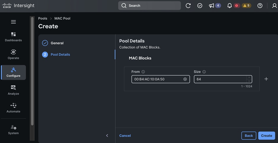
Procedure 2. Create UUID Pools
Step 1. Use a web browser to navigate to intersight.com and log into your account.
Step 2. Go to Configure > Pools.
Step 3. Click Create Pool.
Step 4. Choose UUID.
Step 5. Click Start.
Step 6. In the Pools > UUID window, in the General section, for Organization, choose the previously created organization from the drop-down list.
Step 7. For Name, specify a name for this policy.
Step 8. (Optional) For Set Tags, specify value in key:value format.
Step 9. (Optional) For Description, specify a description for this policy.
Step 10. Click Next.
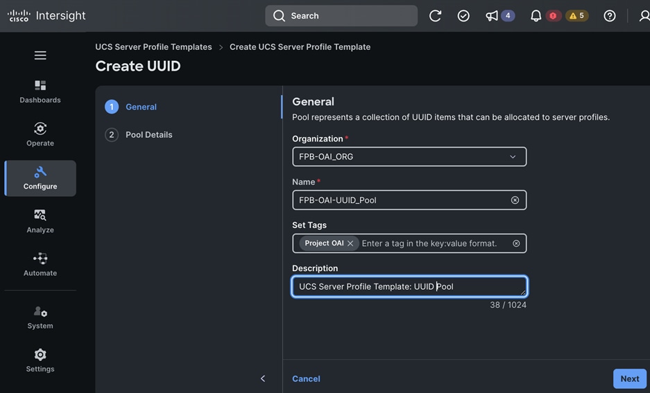
Step 11. In the Pool Details section, specify the Prefix and UUID Blocks with starting value and size.
Step 12. Click + to add additional pools as needed.
Step 13. Click Create. A pop-up message displays stating the policy was created successfully.
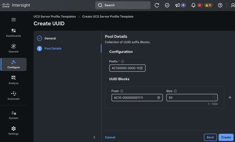
Procedure 3. Create a BIOS Policy
Note: For more information about BIOS tokens and values, see: Performance Tuning Best Practice Guide for Cisco UCS M7 Platforms.
Step 1. Use a web browser to navigate to intersight.com and log into your account.
Step 2. Go to Configure > Policies.
Step 3. Click Create Policy.
Step 4. Choose BIOS.
Step 5. Click Start.
Step 6. In the Policies > BIOS window, in the General section, for Organization, choose the previously created organization from the drop-down list.
Step 7. For Name, specify a name for this policy.
Step 8. (Optional) For Set Tags, specify value in key:value format.
Step 9. (Optional) For Description, specify a description for this policy.
Step 10. Click Next.
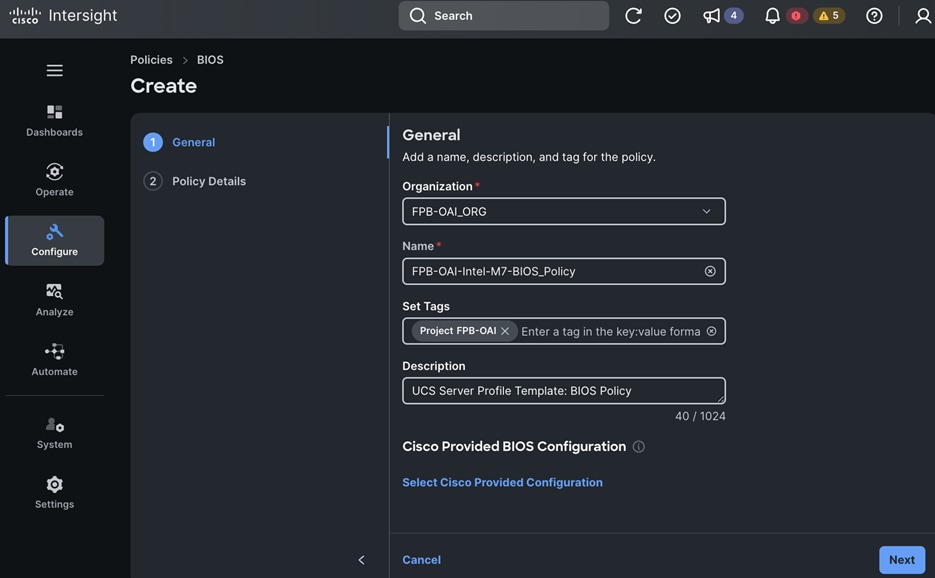
Step 11. In the Policy Details section, expand Processor.
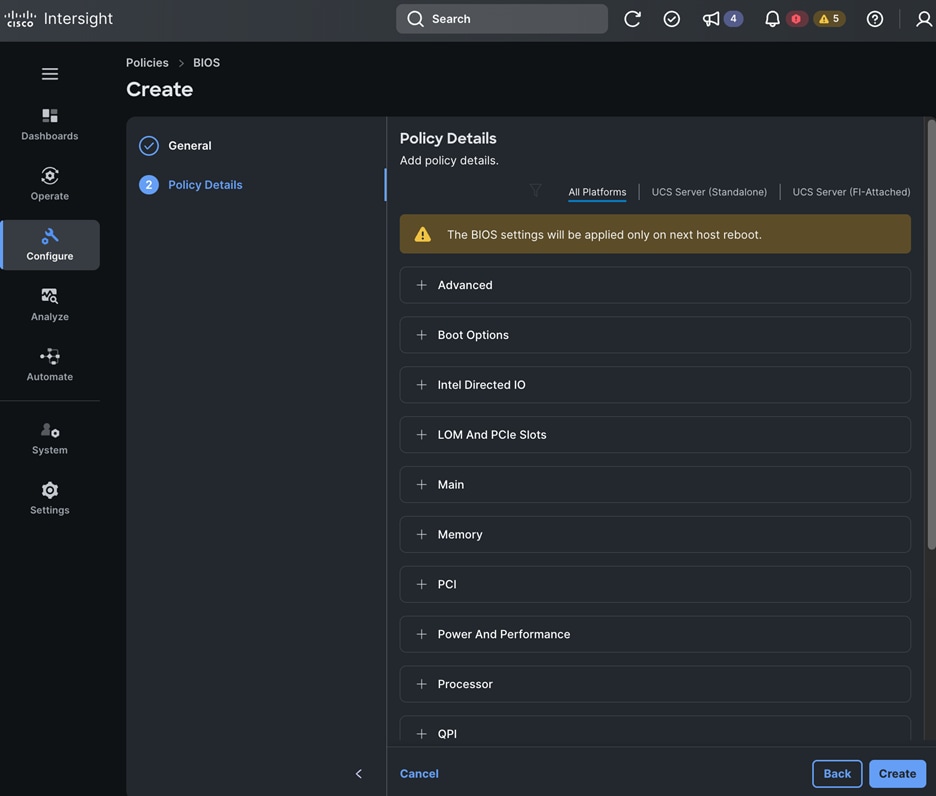
Step 12. From the Intel® VT drop-down list, click disabled.
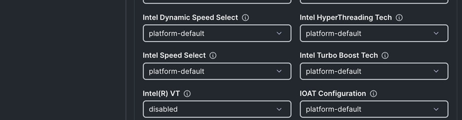
Step 13. In the Policy Details section, expand Processor > Processor C6 Report and from the drop-down list, click enabled.
Step 14. Go to Processor > Workload Configuration and from the drop-down list, click enabled.
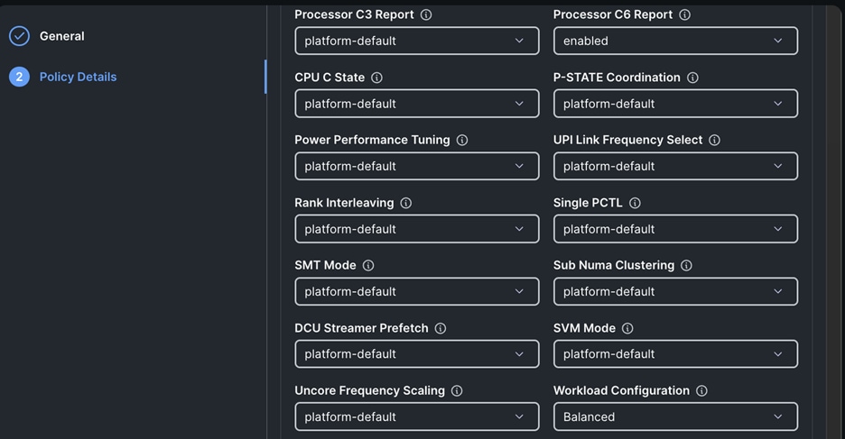
Step 15. In the Policy Details section, expand Server Management > Consistent Device Naming and from the drop-down list, click enabled.
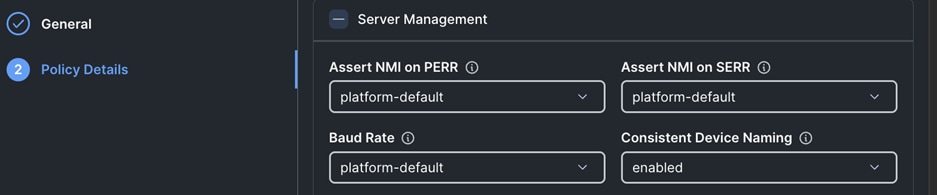
Step 16. Click Create. A pop-up message displays stating the policy was created successfully.
Procedure 4. Create a Boot Order Policy
Note: Do NOT enable Secure Boot. Secure Boot needs to be disabled for NVIDIA GPU Operator in Red Hat OpenShift.
Note: CIMC Mapped Media is not compatible with OOB Management. Please ensure that the associated Server Policy is utilizing an In-Band Management policy.
Step 1. Use a web browser to navigate to intersight.com and log into your account.
Step 2. Go to Configure > Policies.
Step 3. Click Create Policy.
Step 4. Choose Boot Order.
Step 5. Click Start.
Step 6. In the Policies > Boot Order window, in the General section, for Organization, choose the previously created organization from the drop-down list.
Step 7. For Name, specify a name for this policy.
Step 8. (Optional) For Set Tags, specify value in key:value format.
Step 9. (Optional) For Description, specify a description for this policy.
Step 10. Click Next.
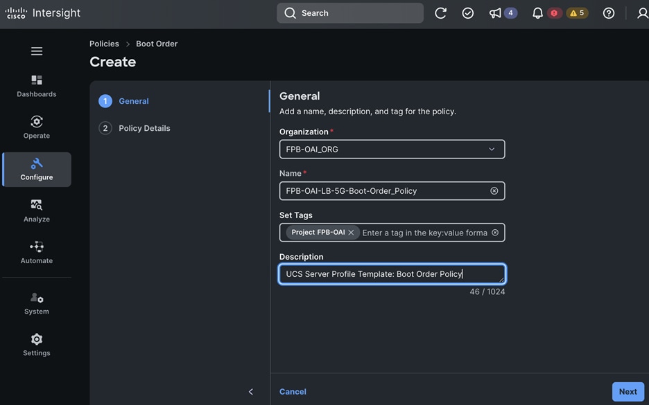
Step 11. In the Policy Details section, leave UEFI enabled and Secure Boot disabled.
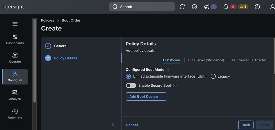
Step 12. Click Add Boot Device and choose Virtual Media from the drop-down list.
Step 13. Configure the Device Name and Sub-Type to mount the ISO using virtual KVM session to the server.
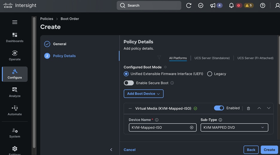
Step 14. Click Add Boot Device and choose Virtual Media from the drop-down list.
Step 15. Configure the Device Name and Sub-Type to mount the ISO using the server’s CIMC.
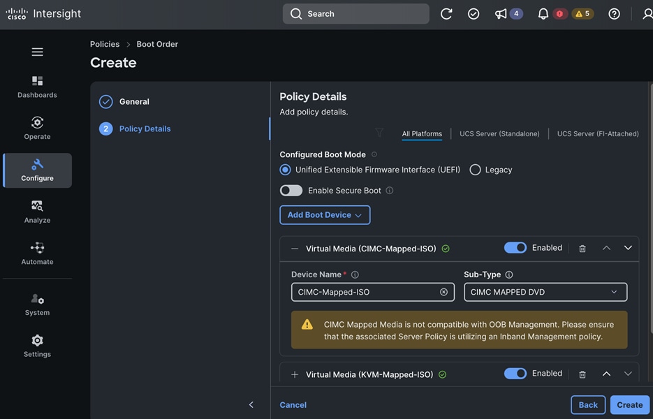
Step 16. Click Add Boot Device and choose Local Disk from the drop-down list.
Step 17. Specify the Device Name and Slot to enable boot from local disk. The Local Disk boot option should be at the top to ensure that the nodes always boot from the M.2 disks once after Red Hat CoreOS is installed on the servers.
Step 18. Click Create. A pop-up message displays stating the policy was created successfully.
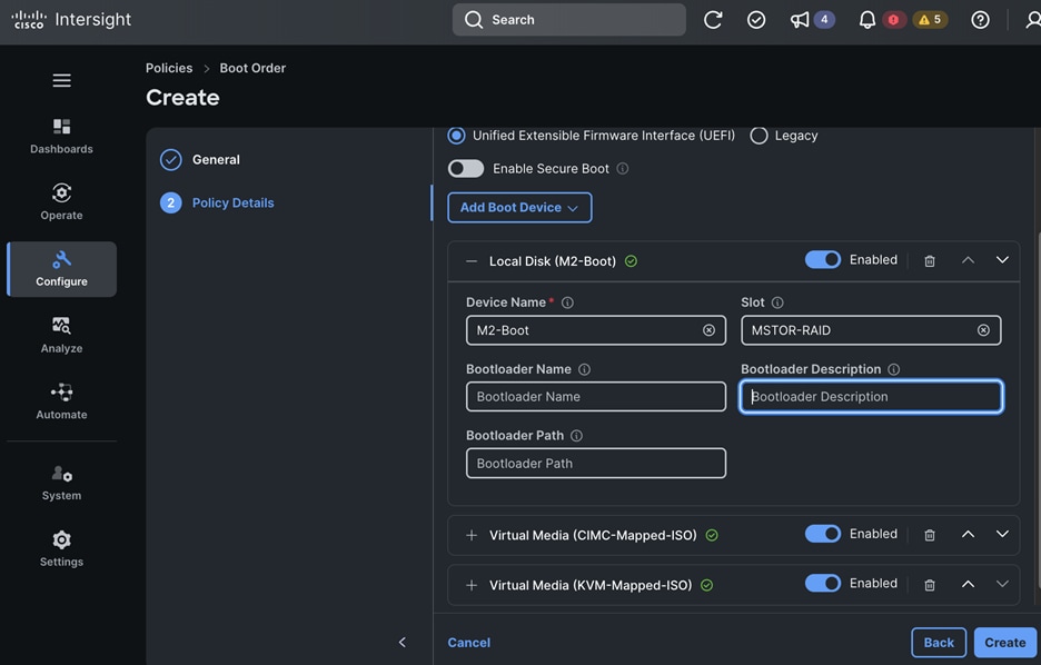
Procedure 5. Create Ethernet Adapter Policies
Step 1. Use a web browser to navigate to intersight.com and log into your account.
Step 2. Go to Configure > Policies.
Step 3. Click Create Policy.
Step 4. Choose Ethernet Adapter to create the first policy.
Step 5. Click Start.
Step 6. In the Policies > Ethernet Adapter window, in the General section, for Organization, choose the previously created organization from the drop-down list.
Step 7. For Name, specify a name for the first policy.
Step 8. (Optional) For Set Tags, specify value in key:value format.
Step 9. (Optional) For Description, specify a description for this policy.
Step 10. Click Next.
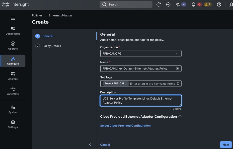
Step 11. Click Select Cisco Provided Configuration and choose Linux-v2 from the drop-down list.
Step 12. Click Select.
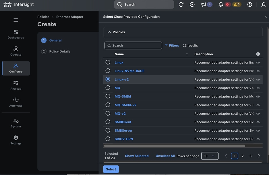
Step 13. Click Next.
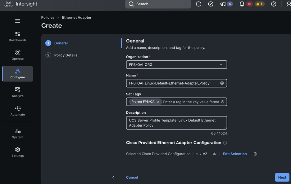
Step 14. Review the Settings for the policy.
Step 15. Click Create. A pop-up message displays stating the policy was created successfully.
Step 16. To create the second ethernet adapter policy, go to Configure > Policies.
Step 17. Click Create Policy.
Step 18. Choose Ethernet Adapter.
Step 19. Click Start.
Step 20. In the Policies > Ethernet Adapter window, in the General section, for Organization, choose the previously created organization from the drop-down list.
Step 21. For Name, specify a name for the first policy.
Step 22. (Optional) For Set Tags, specify value in key:value format.
Step 23. (Optional) For Description, specify a description for this policy using the settings in the Setup Information section.
Step 24. Click Next.

Step 25. Use the settings in Setup Information to configure this policy as shown below:
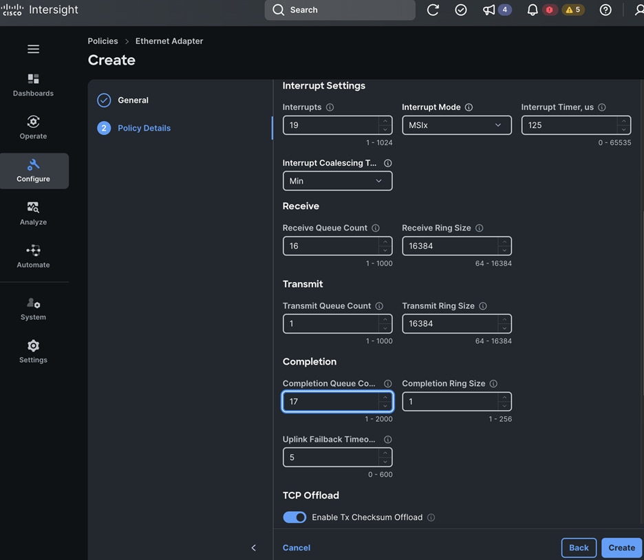
Step 26. Click Create. A pop-up message displays stating the policy was created successfully.
Procedure 6. Create a Ethernet Network Control Policy
Step 1. Use a web browser to navigate to intersight.com and log into your account.
Step 2. Go to Configure > Policies.
Step 3. Click Create Policy.
Step 4. Choose Ethernet Network Control.
Step 5. Click Start.
Step 6. In the Policies > Ethernet Network Control window, in the General section, for Organization, choose the previously created organization from the drop-down list.
Step 7. For Name, specify a name for this policy.
Step 8. (Optional) For Set Tags, specify value in key:value format.
Step 9. (Optional) For Description, specify a description for this policy.
Step 10. Click Next.
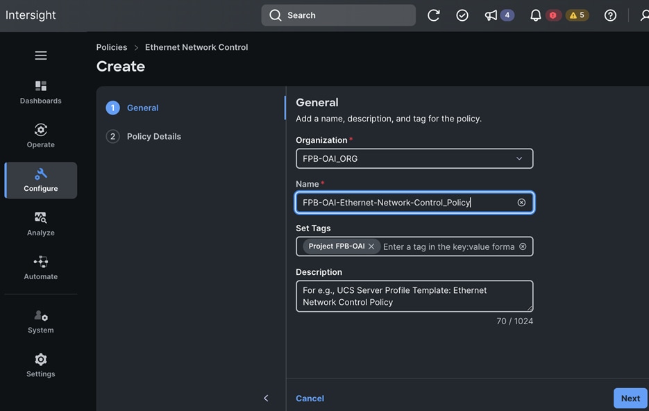
Step 11. In the Policy Details section, enable CDP and LLDP.
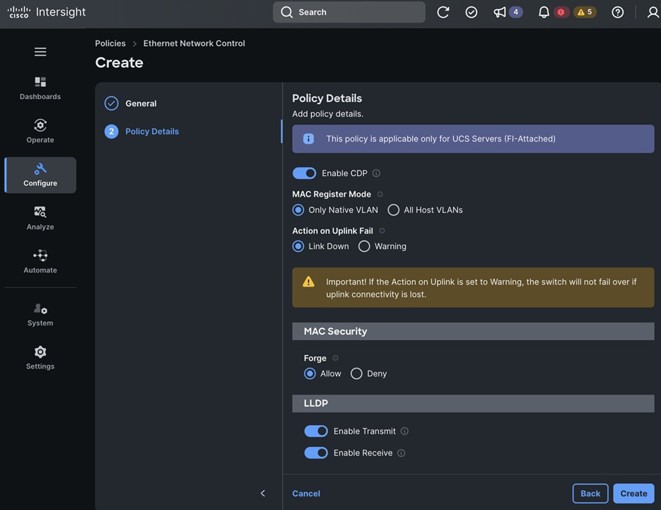
Step 12. Click Create. A pop-up message displays stating the policy was created successfully.
Procedure 7. Create Ethernet Network Group Policies – for In-Band, Cluster Management, and Storage vNICs
Step 1. Use a web browser to navigate to intersight.com and log into your account.
Step 2. Go to Configure > Policies.
Step 3. Click Create Policy.
Step 4. Choose Ethernet Network Group.
Step 5. Click Start.
Step 6. In the Policies > Ethernet Network Group window, in the General section, for Organization, choose the previously created organization from the drop-down list.
Step 7. For Name, specify a name for this policy.
Step 8. (Optional) For Set Tags, specify value in key:value format.
Step 9. (Optional) For Description, specify a description for this policy.
Step 10. Click Next.
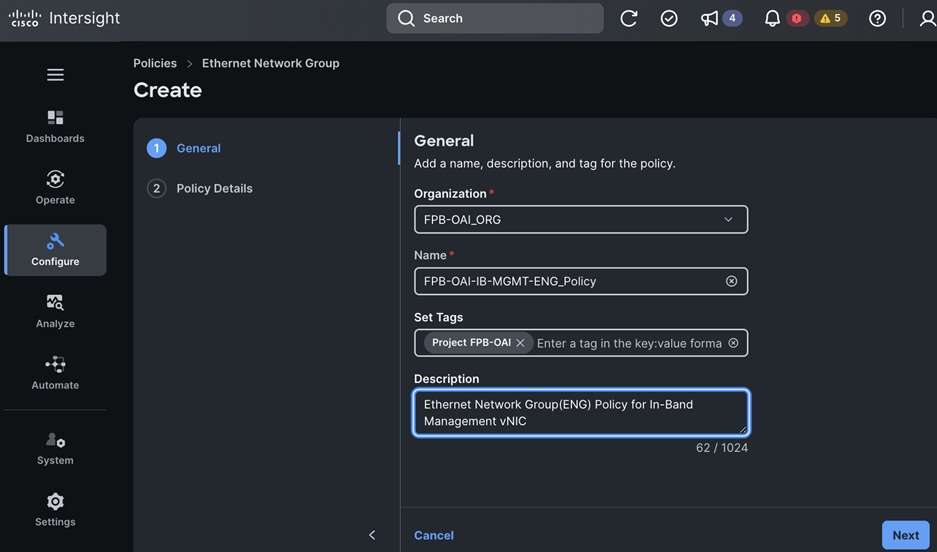
Step 11. In the Policy Details section, click Add VLANs and from the drop-down list, choose From Policy.
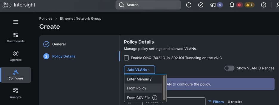
Step 12. In the Select Policy window, choose the previously created VLAN policy.
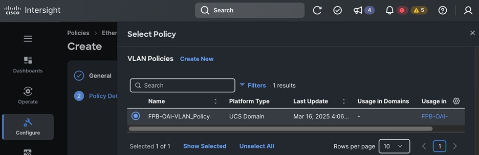
Step 13. Click Next.
Step 14. Choose the VLAN to add to the first vNIC.
Step 15. Click Select.
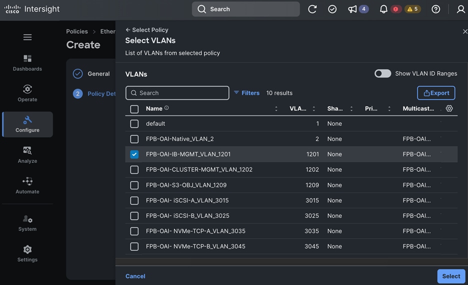
Step 16. In the Policy Details window, choose the VLAN and right-click the elipses and click Set Native VLAN.
Step 17. Click Create. A pop-up message displays stating the policy was created successfully.
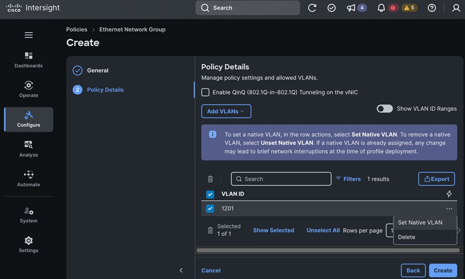
Step 18. Repeat this procedure to create the Ethernet Network Group Policies for the remaining vNICs using the Setup Information for this section.
Procedure 8. Create Ethernet QoS Policies – Default and Jumbo
Step 1. Use a web browser to navigate to intersight.com and log into your account.
Step 2. Go to Configure > Policies.
Step 3. Click Create Policy.
Step 4. Choose Ethernet QoS.
Step 5. Click Start.
Step 6. In the Policies > Ethernet QoS window, in the General section, for Organization, choose the previously created organization from the drop-down list.
Step 7. For Name, specify a name for the first policy.
Step 8. (Optional) For Set Tags, specify value in key:value format.
Step 9. (Optional) For Description, specify a description for this policy.
Step 10. Click Next.
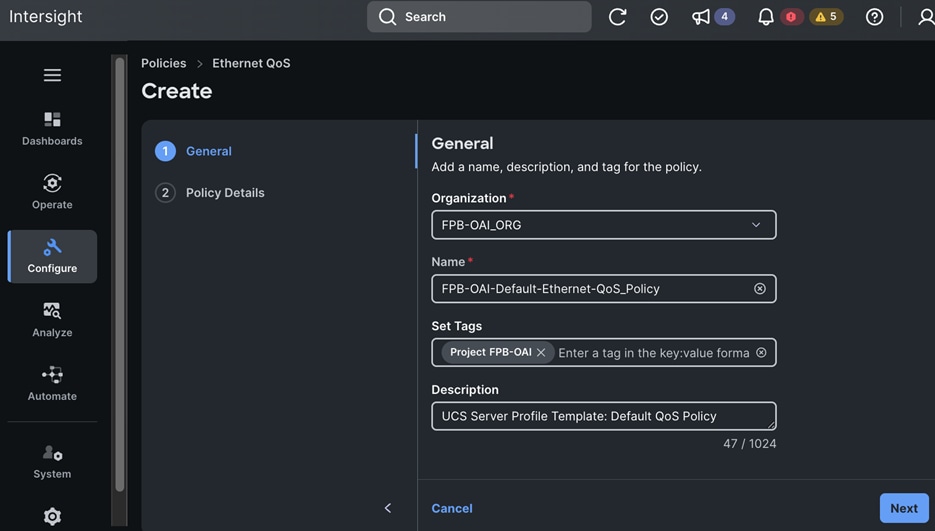
Step 11. In the Policy Details section, keep all default settings.
Step 12. Click Create. A pop-up message displays stating the policy was created successfully.
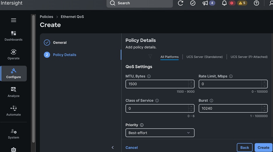
Step 13. Repeat the procedures to create the second policy using the Setup Information for this section.
Step 14. In the Policy Details section, keep the defaults for everything except for the MTU. Set MTU to 9000.
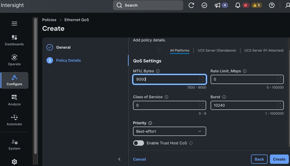
Step 15. Click Create. A pop-up message displays stating the policy was created successfully.
Procedure 9. Create the Firmware Policy
Step 1. Use a web browser to navigate to intersight.com and log into your account.
Step 2. Go to Configure > Policies.
Step 3. Click Create Policy.
Step 4. Choose Firmware.
Step 5. Click Start.
Step 6. In the Policies > Firmware window, in the General section, for Organization, choose the previously created organization from the drop-down list.
Step 7. For Name, specify a name for this policy.
Step 8. Choose Target Platform.
Step 9. (Optional) For Set Tags, specify value in key:value format.
Step 10. (Optional) For Description, specify a description for this policy.
Step 11. Click Next.
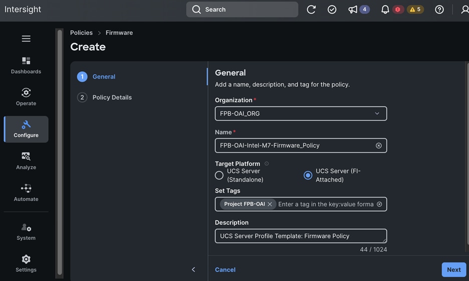
Step 12. In the Policy Details section, choose the Server Model from the drop-down list and Firmware Version to use for the server model.
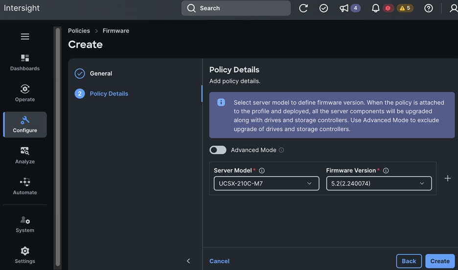
Step 13. Click Create. A pop-up message displays stating the policy was created successfully.
Procedure 10. Create the IPMI over LAN Policy
Step 1. Use a web browser to navigate to intersight.com and log into your account.
Step 2. Go to Configure > Policies.
Step 3. Click Create Policy.
Step 4. Choose IPMI over LAN.
Step 5. Click Start.
Step 6. In the Policies > IPMI over LAN window, in the General section, for Organization, choose the previously created organization from the drop-down list.
Step 7. For Name, specify a name for this policy.
Step 8. (Optional) For Set Tags, specify value in key:value format.
Step 9. (Optional) For Description, specify a description for this policy.
Step 10. Click Next.
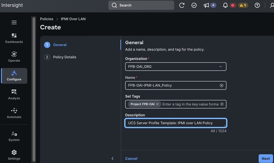
Step 11. In the Policy Details section, keep all the default settings.
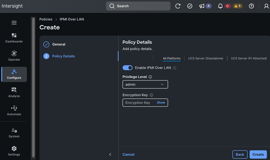
Step 12. Click Create. A pop-up message displays stating the policy was created successfully.
Procedure 11. Create a Local User Policy
Step 1. Use a web browser to navigate to intersight.com and log into your account.
Step 2. Go to Configure > Policies.
Step 3. Click Create Policy.
Step 4. Choose Local User.
Step 5. Click Start.
Step 6. In the Policies > Local User window, in the General section, for Organization, choose the previously created organization from the drop-down list.
Step 7. For Name, specify a name for this policy.
Step 8. (Optional) For Set Tags, specify value in key:value format.
Step 9. (Optional) For Description, specify a description for this policy.
Step 10. Click Next.
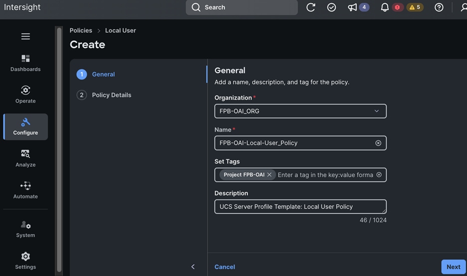
Step 11. In the Policy Details section, click Add Users to add an admin user. Keep the default settings for everything else.
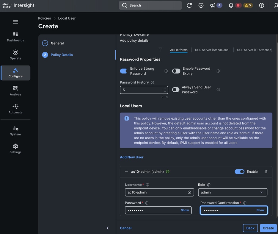
Step 12. Click Create. A pop-up message displays stating the policy was created successfully.
Procedure 12. Create a Storage Policy
Step 1. Use a web browser to navigate to intersight.com and log into your account.
Step 2. Go to Configure > Policies.
Step 3. Click Create Policy.
Step 4. Choose Storage.
Step 5. Click Start.
Step 6. In the Policies > Storage window, in the General section, for Organization, choose the previously created organization from the drop-down list.
Step 7. For Name, specify a name for this policy.
Step 8. (Optional) For Set Tags, specify value in key:value format.
Step 9. (Optional) For Description, specify a description for this policy.
Step 10. Click Next.
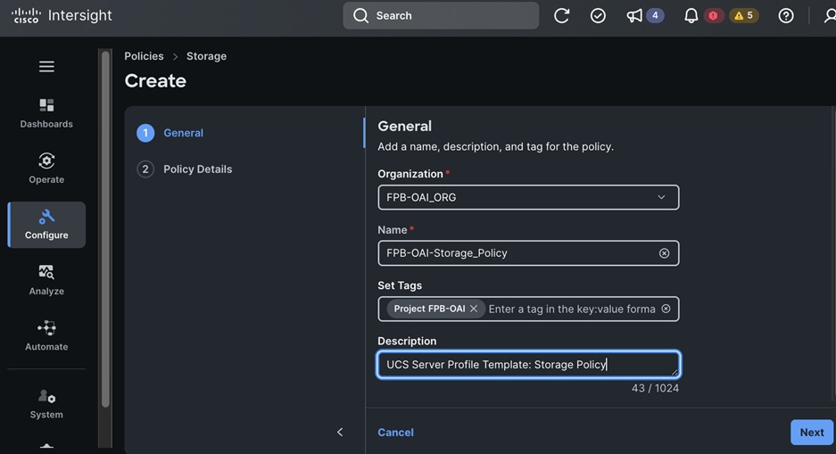
Step 11. In the Policy Details section, enable M.2 RAID Configuration. Keep the defaults settings for everything else.
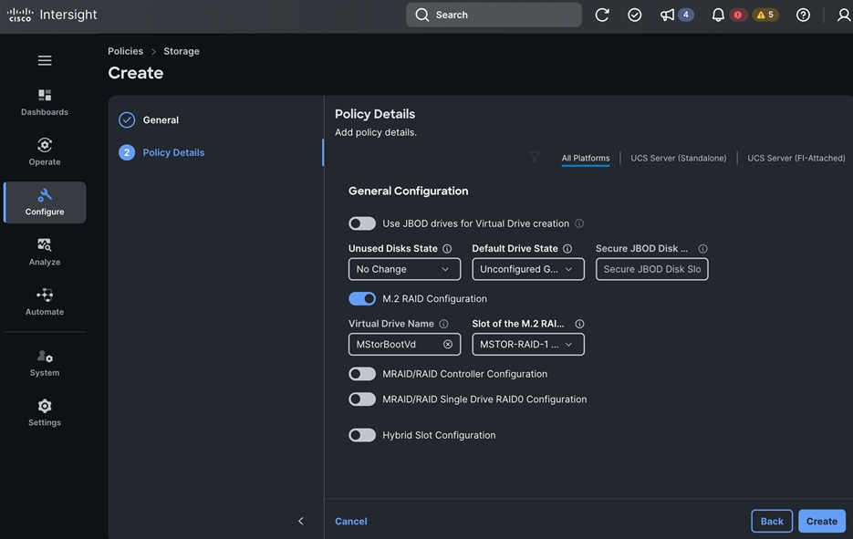
Step 12. Click Create. A pop-up message displays stating the policy was created successfully.
Procedure 13. Create Virtual KVM Policy
Step 1. Use a web browser to navigate to intersight.com and log into your account.
Step 2. Go to Configure > Policies.
Step 3. Click Create Policy.
Step 4. Choose Power.
Step 5. Click Start.
Step 6. In the Policies > Power window, in the General section, for Organization, choose the previously created organization from the drop-down list.
Step 7. For Name, specify a name for this policy.
Step 8. (Optional) For Set Tags, specify value in key:value format.
Step 9. (Optional) For Description, specify a description for this policy.
Step 10. Click Next.
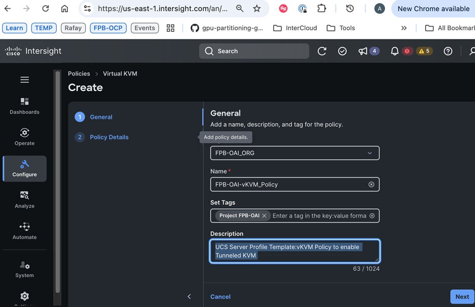
Step 11. In the Policy Details section, enable Allow Tunneled vKVM. Keep the default settings for everything else.
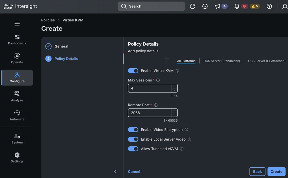
Step 12. Click Create. A pop-up message displays stating the policy was created successfully.
Procedure 14. Create a Virtual Media Policy
Step 1. Use a web browser to navigate to intersight.com and log into your account.
Step 2. Go to Configure > Policies.
Step 3. Click Create Policy.
Step 4. Choose Virtual Media.
Step 5. Click Start.
Step 6. In the Policies > Virtual Media window, in the General section, for Organization, choose the previously created organization from the drop-down list.
Step 7. For Name, specify a name for this policy.
Step 8. (Optional) For Set Tags, specify value in key:value format.
Step 9. (Optional) For Description, specify a description for this policy.
Step 10. Click Next.
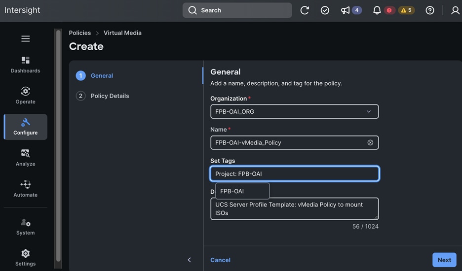
Step 11. In the Policy Details section, keep the default settings.
Step 12. Click Add Virtual Media.
Step 13. In the Add Virtual Media window, use the settings in Setup Information to configure the policy.
Step 14. Click Add.
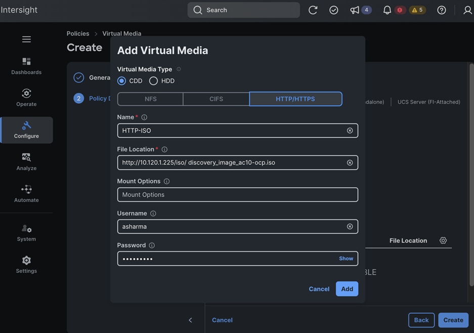
Step 15. Click Create. A pop-up message displays stating the policy was created successfully.
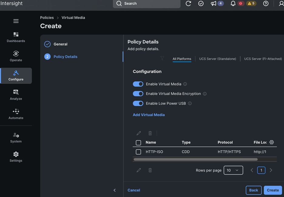
Deployment Steps – vNIC Templates
Use the Setup Information to configure vNIC templates for the UCS server. The vNIC templates will be used by the LAN connectivity policy that will be part of the UCS Server Profile Template which will be used to derive the UCS Server Profile to configure Cisco UCS servers.
Procedure 1. Create a vNIC Template for In-Band Management
Step 1. Use a web browser to navigate to intersight.com and log into your account.
Step 2. Go to Configure > Templates from the left navigation pane.
Step 3. Choose the vNIC Templates tab and click Create vNIC Template.
Step 4. In the Create vNIC Template window, in the General section, for Organization, choose the previously created organization from the drop-down list.
Step 5. For Name, specify a name for this policy.
Step 6. (Optional) For Set Tags, specify value in key:value format.
Step 7. (Optional) For Description, specify a description for this policy.
Step 8. Click Next.
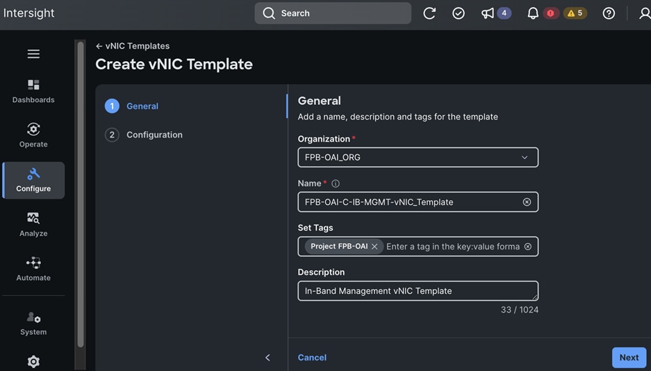
Step 9. In the Configuration section, for MAC Pool, click Select Pool to choose the MAC pool for Fabric-A (FI-A).
Step 10. Enable Failover.
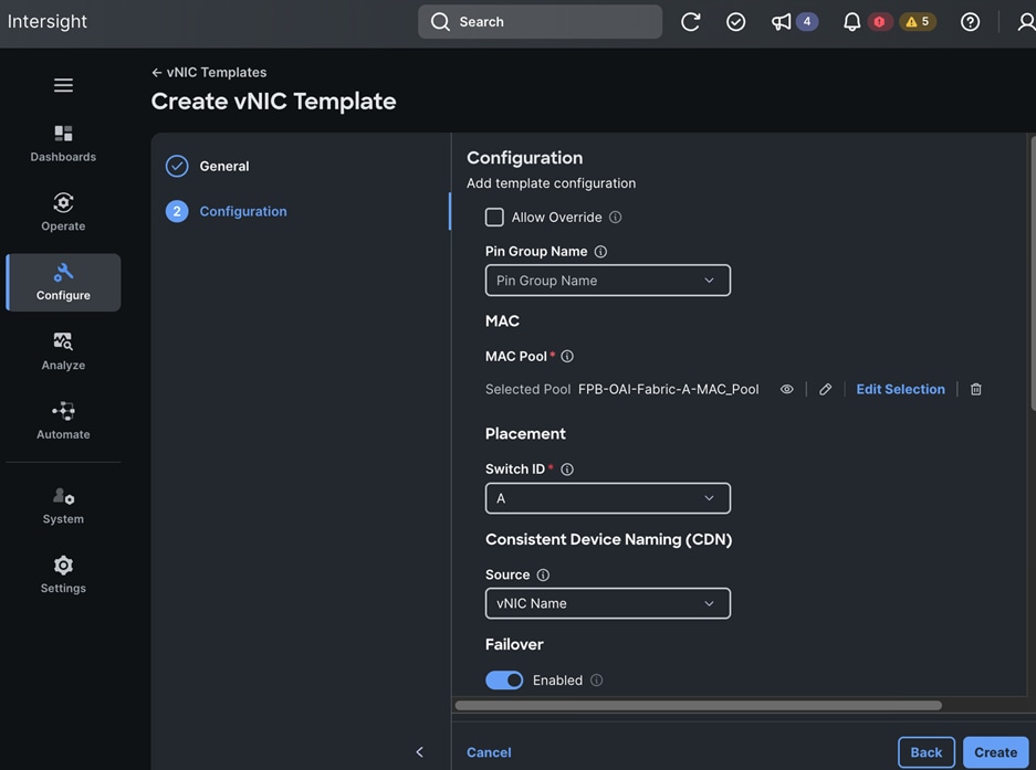
Step 11. For Ethernet Network Group, click Select Policies to choose the policy for this vNIC template.
Step 12. For Ethernet Network Control, click Select Policy to choose the policy for this vNIC template.
Step 13. For Ethernet QoS, click Select Policy to choose the policy for this vNIC template.
Step 14. For Ethernet Adapter, click Select Policy to choose the policy for this vNIC template.
Step 15. Keep the default settings for everything else.
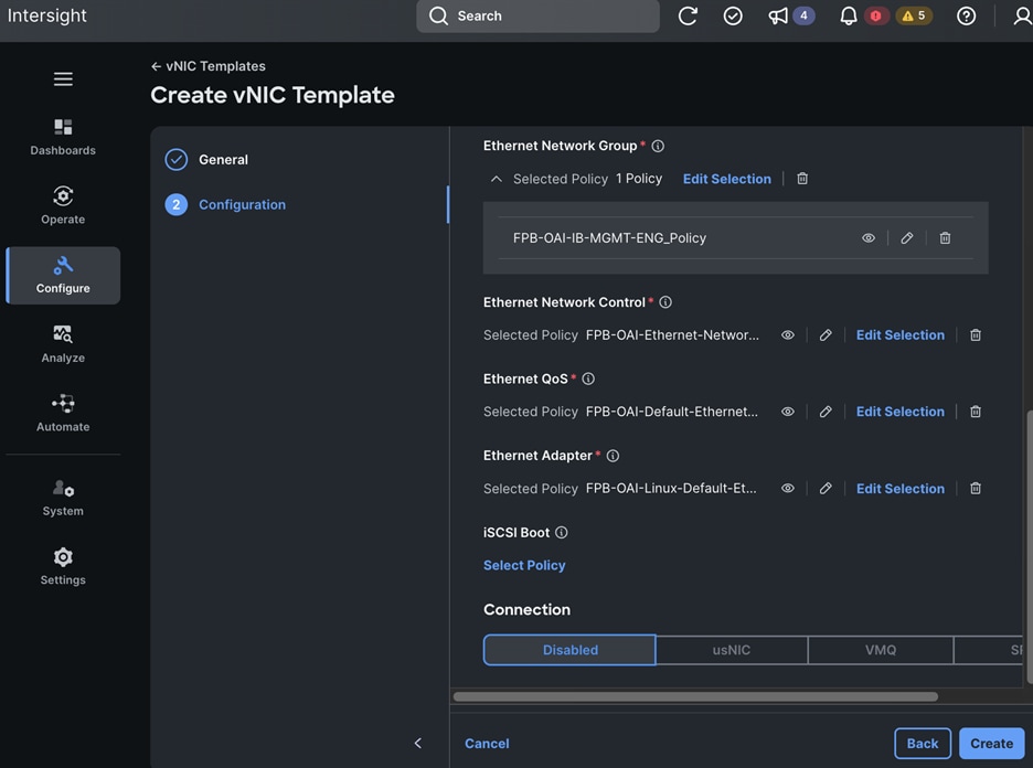
Step 16. Click Create. A pop-up message displays stating the policy was created successfully.
Procedure 2. Create a vNIC Template for OpenShift Cluster Management
Step 1. Repeat the deployment steps in the previous procedure to deploy a vNIC template for OpenShift Cluster. Use the settings from the Setup Information for this section.
Procedure 3. Create a vNIC Template for iSCSI-A storage
Step 1. Repeat the deployment steps in the previous procedure to deploy a vNIC template for iSCSI-A. Use the settings from the Setup Information for this section.
Procedure 4. Create a vNIC Templates for iSCSI-B storage
Step 1. Repeat the deployment steps in the previous procedure to deploy a vNIC template for iSCSI-B. Use the settings from the Setup Information for this section.
Procedure 5. Create a vNIC Templates for NFS Storage access
Step 1. Repeat the deployment steps in the previous procedure to deploy a vNIC template for NFS storage. Use the settings from the Setup Information for this section.
Procedure 6. Create a vNIC Templates for Object Store access
Step 1. Repeat the deployment steps in the previous procedure to deploy a vNIC template for Object store. Use the settings from the Setup Information for this section.
Deployment Steps – LAN Connectivity Policy
Use the Setup Information to configure LAN Connectivity policy for the UCS server. This policy is part of the UCS Server Profile Template which is used to derive the UCS Server Profile to configure Cisco UCS servers.
Procedure 1. Create LAN Connectivity Policy for OpenShift Control Nodes
Step 1. Use a web browser to navigate to intersight.com and log into your account.
Step 2. Go to Configure > Policies.
Step 3. Click Create Policy.
Step 4. Choose LAN Connectivity.
Step 5. Click Start.
Step 6. In the Policies > LAN Connectivity window, in the General section, for Organization, choose the previously created organization from the drop-down list.
Step 7. For Name, specify a name for this policy.
Step 8. Choose Target Platform.
Step 9. (Optional) For Set Tags, specify value in key:value format.
Step 10. (Optional) For Description, specify a description for this policy.
Step 11. Click Next.
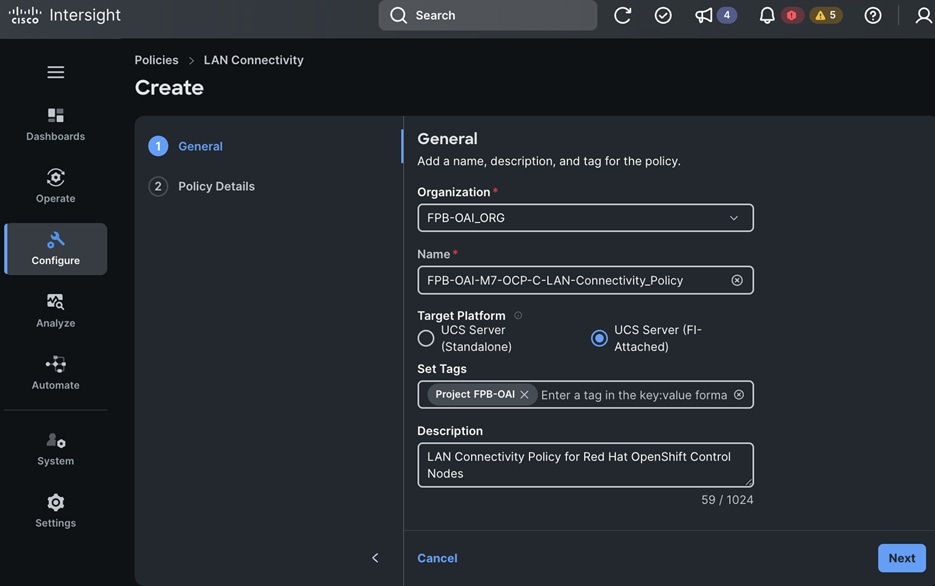
Step 12. In the Policy Details section, under vNIC Configuration, click Add and choose vNIC from Template from the drop-down list.

Step 13. In the Add vNIC from Template window, click Select vNIC Template.
Step 14. Choose the vNIC Template from the list.
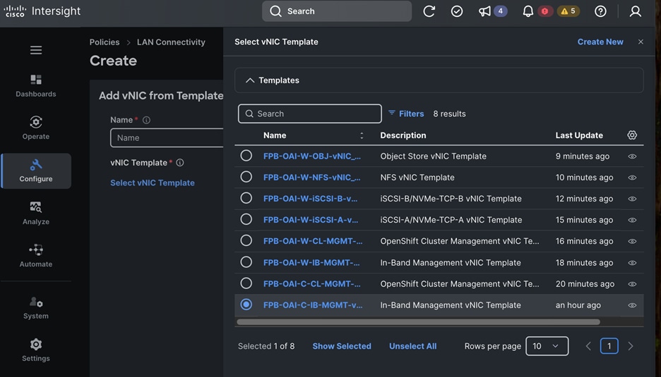
Step 15. Click Select.
Step 16. Specify a Name and PCI Order for this NIC.
Step 17. Click Add.
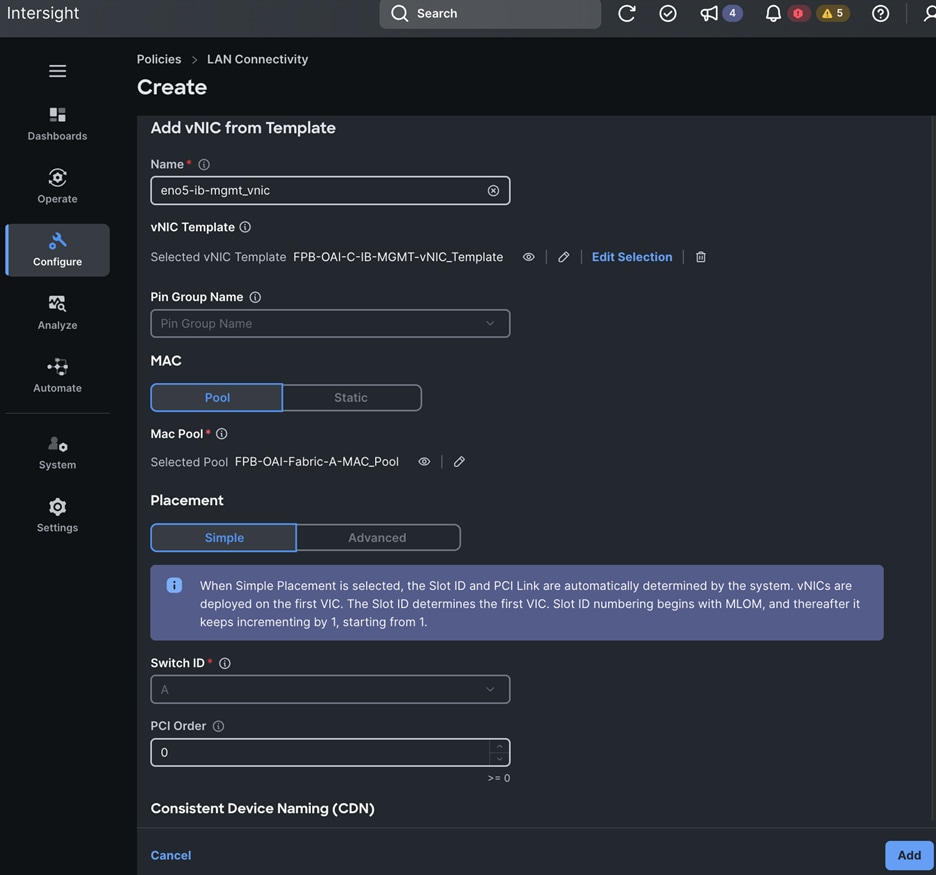
Step 18. To add additional vNICs, repeat steps 1 – 17 of this procedure. In the Policy Details section, under vNIC Configuration, click Add and choose vNIC from Template from the drop-down list to add additional vNICs. Provide a unique Name and PCI Order for each new vNIC.
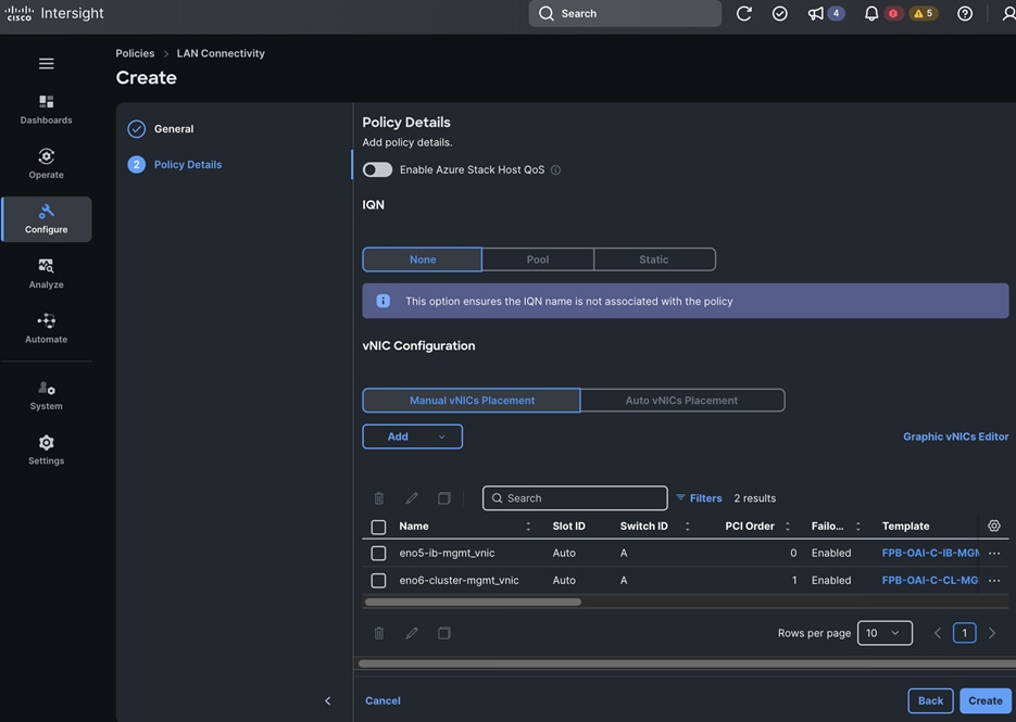
Step 19. Click Create. A pop-up message displays stating the policy was created successfully.
Procedure 2. Create a LAN Connectivity Policy for OpenShift Worker Nodes
Step 1. Use a web browser to navigate to intersight.com and log into your account.
Step 2. Go to Configure > Policies.
Step 3. Click Create Policy.
Step 4. Choose LAN Connectivity.
Step 5. Click Start.
Step 6. In the Policies > LAN Connectivity window, in the General section, for Organization, choose the previously created organization from the drop-down list.
Step 7. For Name, specify a name for this policy.
Step 8. Choose Target Platform.
Step 9. (Optional) For Set Tags, specify value in key:value format.
Step 10. (Optional) For Description, specify a description for this policy.
Step 11. Click Next.
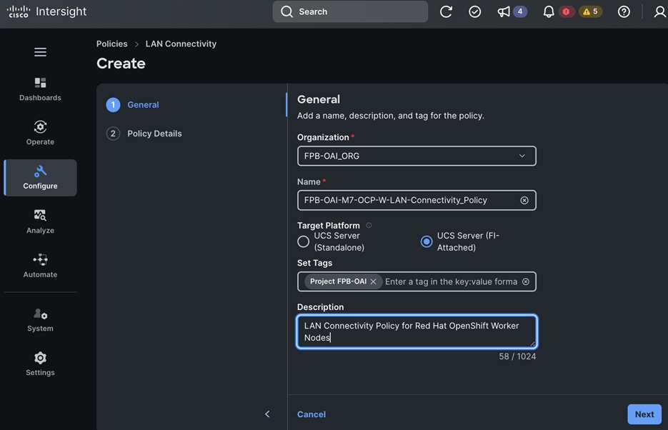
Step 12. In the Policy Details section, under vNIC Configuration, click Add and choose vNIC from Template from the drop-down list.
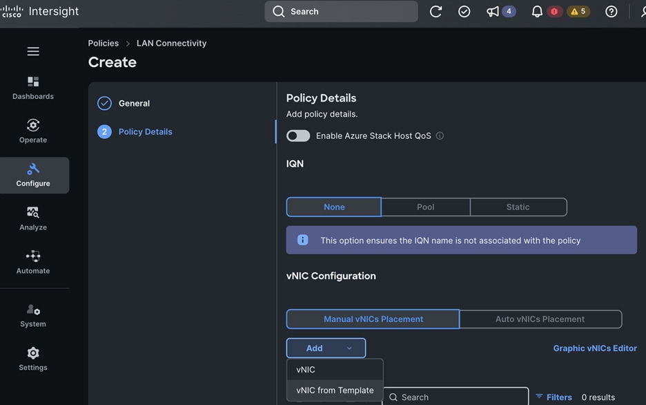
Step 13. In the Add vNIC from Template window, click Select vNIC Template.
Step 14. Choose the vNIC Template from the list.
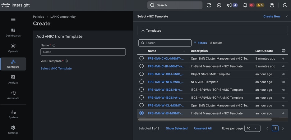
Step 15. Click Select.
Step 16. Specify a Name and PCI Order for this NIC.

Step 17. Click Add.
Step 18. Repeat steps 1 – 17 in this procedure to add the remaining vNICs. In the Policy Details section, under vNIC Configuration, click Add and then choose vNIC from Template from the drop-down list to add additional vNICs. Provide a unique Name and PCI Order for each new vNIC.
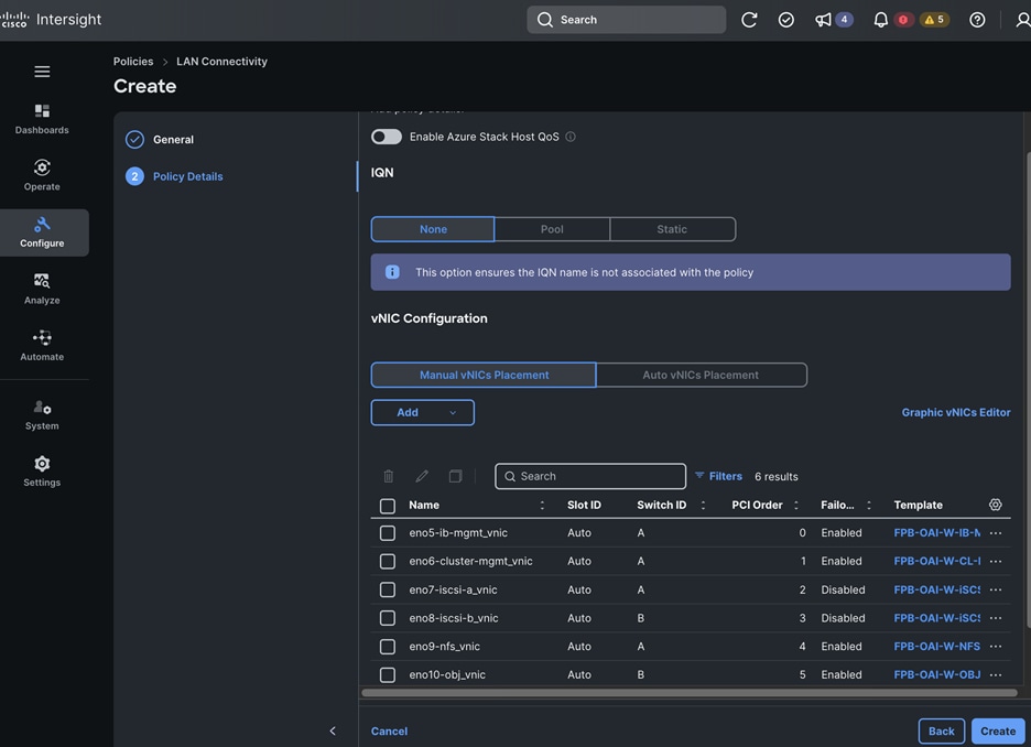
Step 19. Click Create. A pop-up message displays stating the policy was created successfully.
Deployment Steps – Server Profile Template
Use the Setup Information to create a Cisco UCS Server Profile Template. This template is used to derive the UCS Server Profile(s) to provision individual UCS servers.
Procedure 1. Create UCS Server Profile Template for OpenShift Control Nodes
Step 1. Use a web browser to navigate to intersight.com and log into your account.
Step 2. Go to Configure > Templates.
Step 3. Choose the UCS Server Profile Templates tab. Click UCS Server Profile Template.
Step 4. In the Create UCS Server Profile Template window, in the General section, for Organization, choose the previously created organization from the drop-down list.
Step 5. For Name, specify a name for this template.
Step 6. For Target, choose a UCS platform.
Step 7. (Optional) For Set Tags, specify value in key:value format.
Step 8. (Optional) For Description, specify a description for this policy.
Step 9. Click Next.
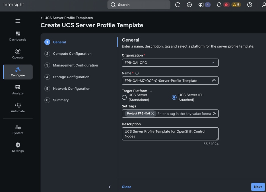
Step 10. In the Compute Configuration section, choose the previously created pools and policies.
Step 11. Click Next.
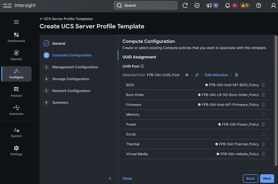
Step 12. In the Management Configuration section, choose the previously created pools and policies.
Step 13. Click Next.
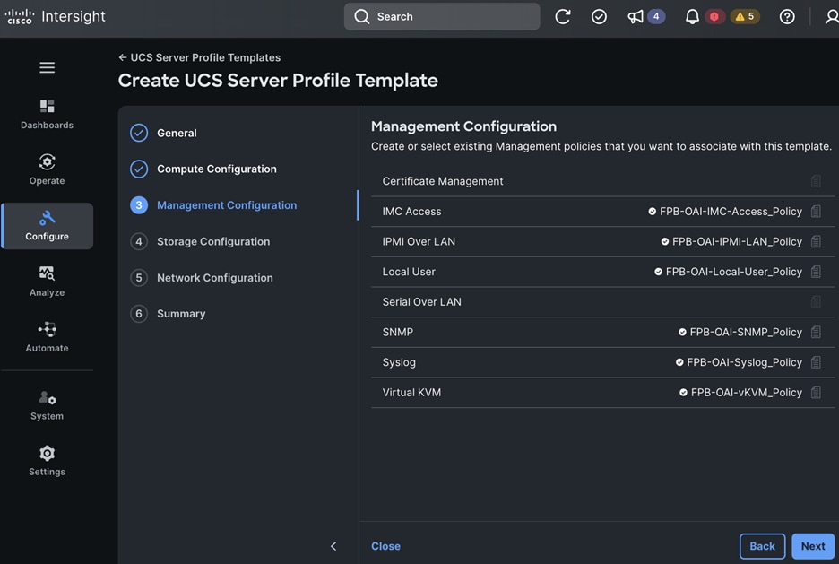
Step 14. In the Storage Configuration section, choose the previously created pools and policies.
Step 15. Click Next.
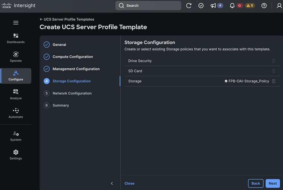
Step 16. In the Network Configuration section, choose the previously created Connectivity Policies.
Step 17. Click Next.
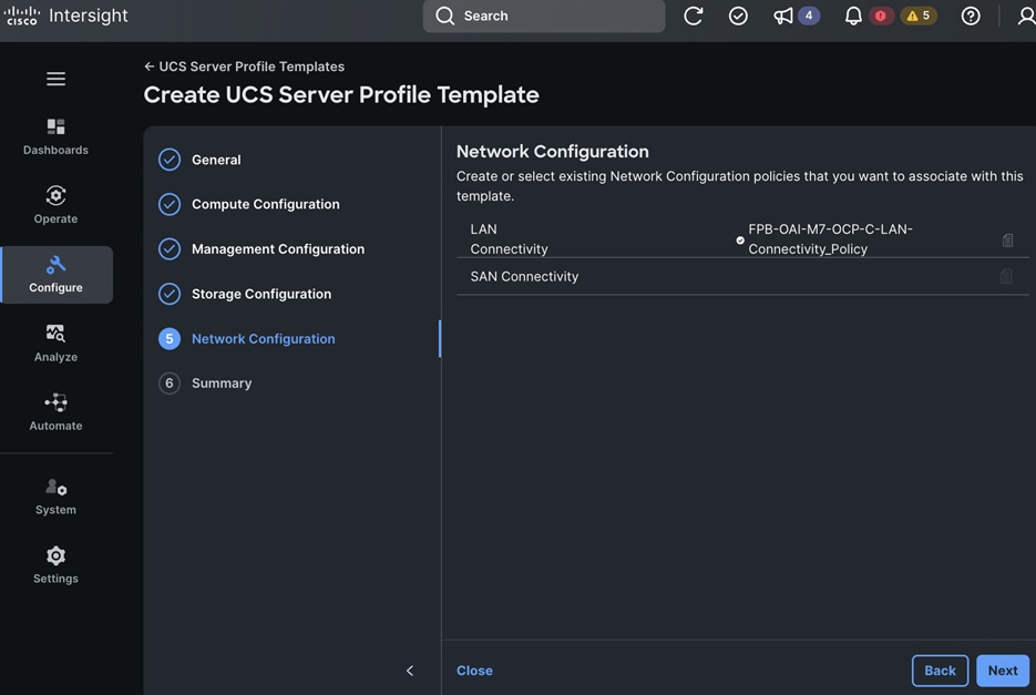
Step 18. In the Summary section, review the selections made.
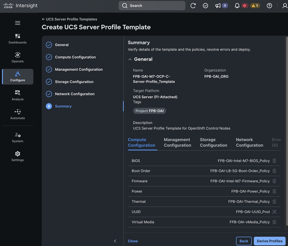
Step 19. Click Close – the profile will be derived at a later time.
Procedure 2. Create UCS Server Profile Template for OpenShift Worker Nodes
Step 1. Use a web browser to navigate to intersight.com and log into your account.
Step 2. Go to Configure > Templates from the left navigation pane.
Step 3. Choose the UCS Server Profile Templates tab. Click UCS Server Profile Template.
Step 4. In the Create UCS Server Profile Template window, in the General section, for Organization, choose the previously created organization from the drop-down list.
Step 5. For Name, specify a name for this template.
Step 6. For Target Platform, choose a UCS platform.
Step 7. (Optional) For Set Tags, specify value in key:value format.
Step 8. (Optional) For Description, specify a description for this policy.
Step 9. Click Next.
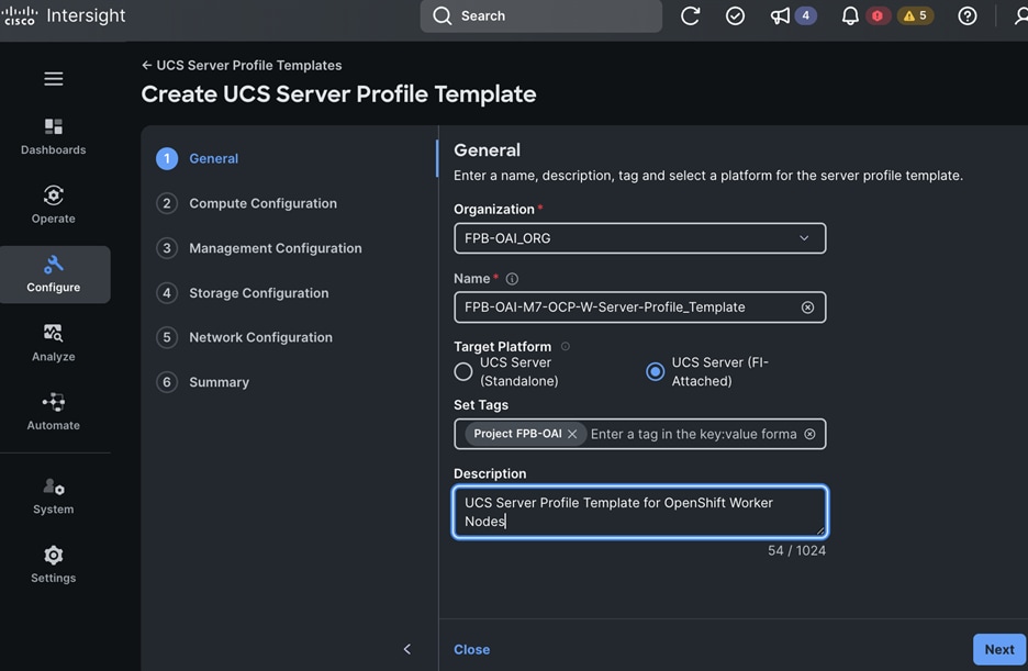
Step 10. In the Compute Configuration section, choose the previously created pools and policies.
Step 11. Click Next.
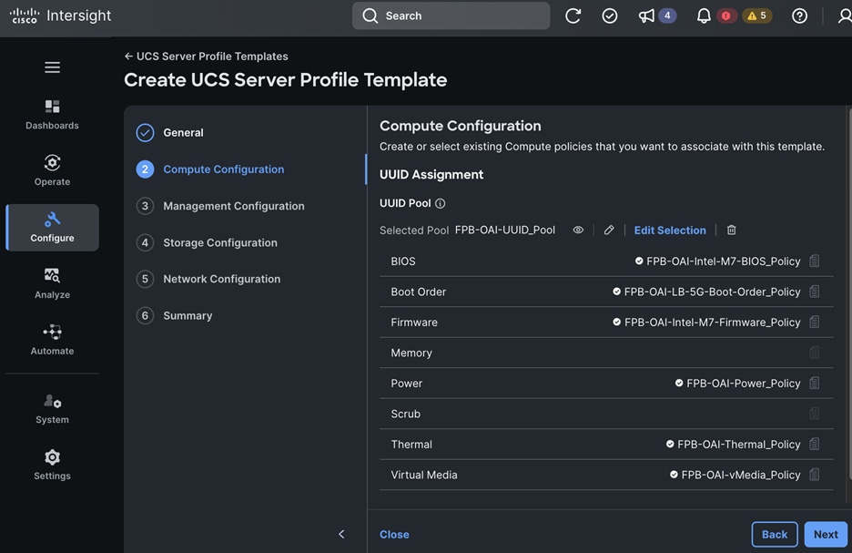
Step 12. In the Management Configuration section, choose the previously created pools and policies.
Step 13. Click Next.
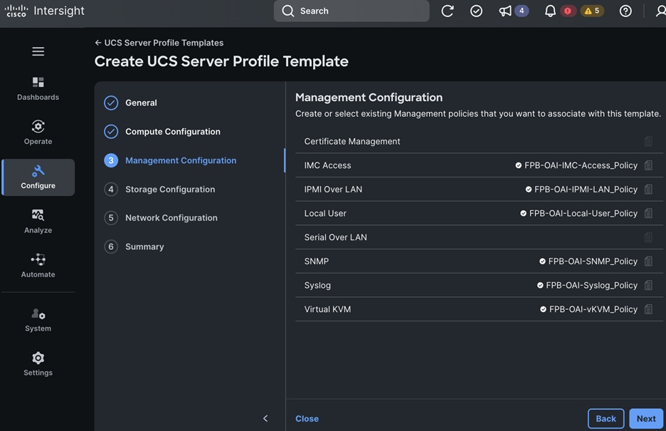
Step 14. In the Storage Configuration section, choose the previously created pools and policies.
Step 15. Click Next.

Step 16. In the Network Configuration section, choose the previously created Connectivity Policies.
Step 17. Click Next.
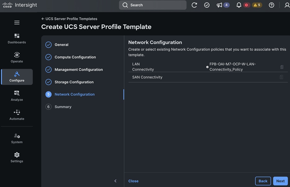
Step 18. In the Summary section, review the selections made.
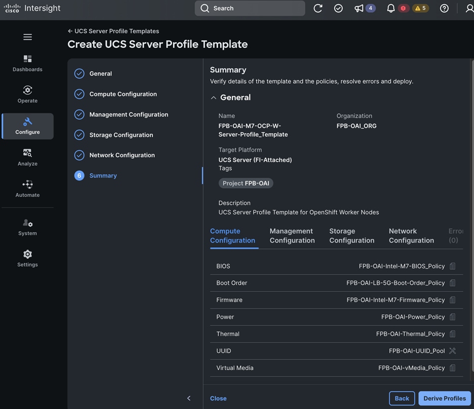
Step 19. Click Close – the profile will be derived at a later time.
Deployment Steps – Derive Server Profile(s)
The procedures in this section derive the UCS Server Profile(s) to configure UCS servers from a previously provisioned UCS Server Profile Template.
Procedure 1. Derive the UCS Server Profile(s) for OpenShift Control Nodes
Step 1. Use a web browser to navigate to intersight.com and log into your account.
Step 2. Go to Configure > Templates.
Step 3. Choose UCS Server Profile Templates.
Step 4. Choose a UCS Server Profile Template to use.
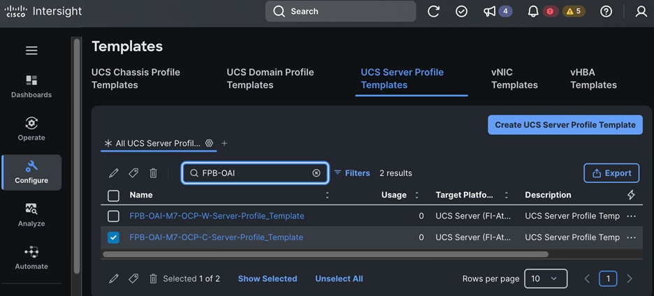
Step 5. Click the elipses and choose Derive Profiles from the drop-down list.
Step 6. Click Next.
Step 7. In the UCS Server Profile Template > FPB-OAI-M7-OCP-C-Server-Profile_Template window, in the General section, choose Assign Later, and specify the Number of Profiles to derive in the box provided.
Step 8. Click Next.
Step 9. In the Details section, specify the naming format for the profiles.
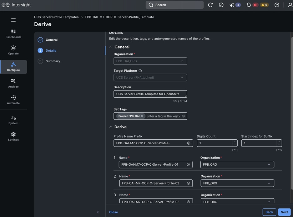
Step 10. Click Next.
Step 11. In the Summary section, review the information.
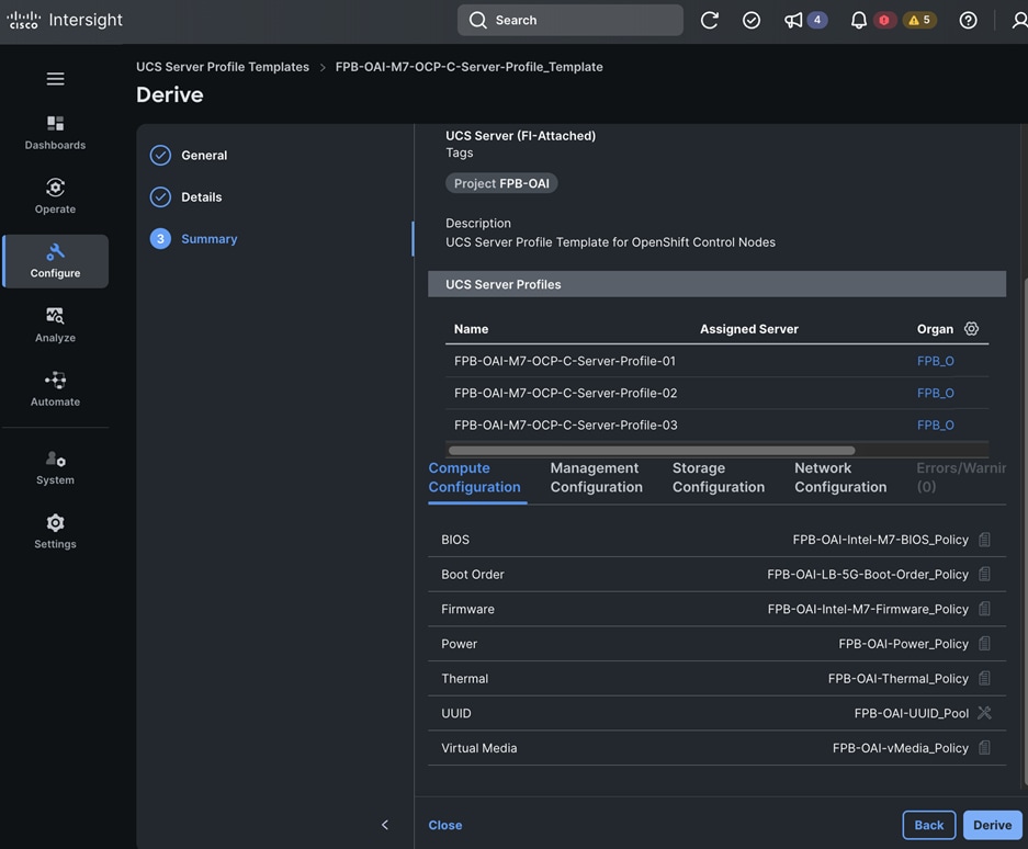
Step 12. Click Derive to derive server profiles to configure the OpenShift Control Nodes.
Procedure 2. Derive UCS Server Profile(s) for OpenShift Worker Nodes
Step 1. Use a web browser to navigate to intersight.com and log into your account.
Step 2. Go to Configure > Templates.
Step 3. Choose UCS Server Profile Templates.
Step 4. Choose UCS Server Profile Template to use.
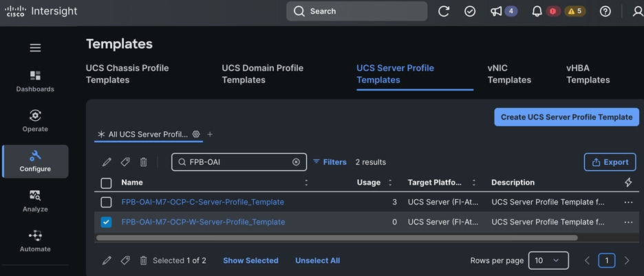
Step 5. Click the elipses and choose Derive Profiles from the drop-down list.
Step 6. Click Next.
Step 7. In the UCS Server Profile Template > FPB-OAI-M7-OCP-W-Server-Profile_Template window, in the General section, choose Assign Later, and specify the Number of Profiles to derive in the box provided.
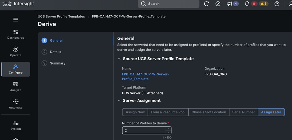
Step 8. Click Next.
Step 9. In the Details section, specify the naming format for the profiles.
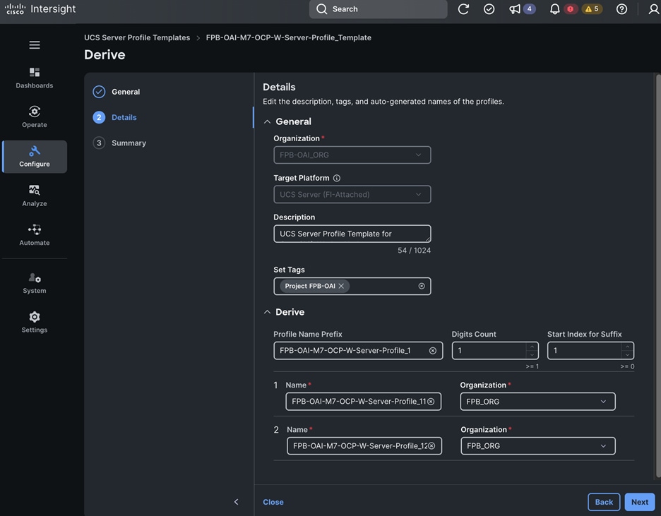
Step 10. Click Next.
Step 11. In the Summary section, review the information.
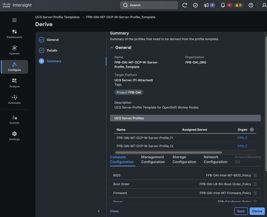
Step 12. Click Derive to derive server profiles to configure the OpenShift Control Nodes.
Deployment Steps – Deploy Server Profile(s)
The procedures in this section deploy server profiles that provision the servers.
Procedure 1. Deploy and Assign Cisco UCS Server Profiles to configure OpenShift Control and Worker Nodes
Step 1. Use a web browser to navigate to intersight.com and log into your account.
Step 2. Go to Configure > Profiles.
Step 3. Choose UCS Server Profiles.
Step 4. Choose a previously derived UCS Server Profiles from the list.
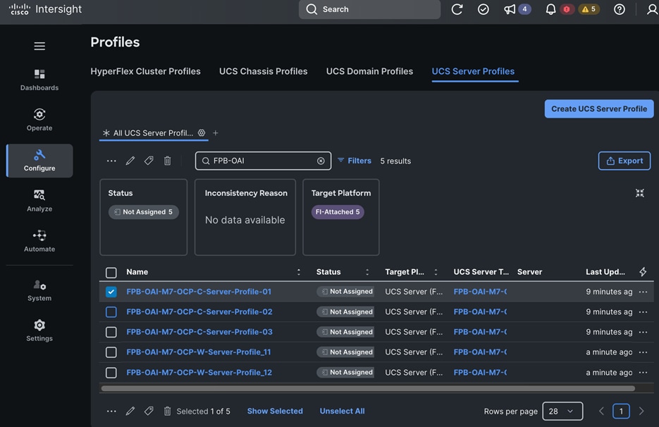
Step 5. Click the elipses and choose Assign Server from the list.
Step 6. Choose the UCS server to deploy the profile.
Step 7. Click Assign.
Step 8. Repeat steps 1 – 7 to assign the remaining server profiles.
Step 9. To deploy the server, click the elipses and click Deploy from the drop-down list.
Step 10. In the Deploy UCS Server Profile pop-up window, make the selections to activate and reboot the server.
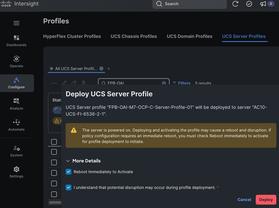
Step 11. Click Deploy. The system will validate and provision the settings on the selected servers.
Step 12. Repeat this procedure to assign and deploy server profiles to all OpenShift control and worker nodes in the cluster being built.
Procedure 2. Verify that UCS Server Profiles were deployed successfully
Step 1. Use a web browser to navigate to intersight.com and log into your account.
Step 2. Go to Configure > Profiles.
Step 3. Choose UCS Server Profiles.
Step 4. Verify that all server profiles have a Status of OK with the profile Name and the server on which it was deployed.
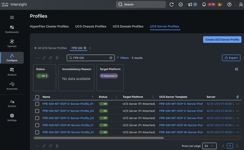
Deploy Kubernetes – OpenShift on Baremetal UCS Servers
This section provides the detailed procedures for deploying a Red Hat OpenShift Kubernetes (K8s) cluster in an Enterprise data center. The cluster will be used for hosting AI/ML workloads managed using Red Hat OpenShift AI serving as the MLOps platform for this solution. The OpenShift cluster is deployed from the cloud using Red Hat Hybrid Cloud Console using the Red Hat recommended Assisted Installer. Red Hat provides other installation options depending on the level of customization required.
Note: Assisted Installer also provides Cisco Intersight integration that makes the deployment of a baremetal cluster significantly easier.
Prerequisites
● Complete compute, network and storage setup which includes:
◦ Intersight managed Cisco UCS servers that serve as control and worker nodes in the OpenShift cluster
◦ Setup of NetApp storage for providing NFS, S3-compatible Object and IP based block storage access using iSCSI/NVMe over TCP.
◦ Networking enabled through Top-of-Rack Cisco Nexus switches with access from compute to storage as well as external access with reachability to quay.io, Red Hat’s Hybrid Cloud Console, and so on. The IP subnet for the OpenShift cluster should be reachable from the Installer and should have access to network services (see prerequisites below)
● Valid Red Hat account on Red Hat’s Hybrid Cloud Console (console.redhat.com) to access and deploy the cluster using Red Hat’s Assisted installer
● OpenShift requires the following components to be in place before the installation:
◦ Installer workstation or machine for OpenShift cluster management – Rocky Linux is used in this CVD. This installer provides CLI access to the cluster. More importantly, it provides secure SSH access to nodes in the cluster post-deployment. This requires prerequisite setup (see below) before the cluster is deployed.
◦ To enable SSH Access to the OpenShift cluster, public keys must be provided to the OpenShift installer. Installer will pass the keys to the nodes through the initial configuration (ignition) files during installation. The nodes will add the keys to the ~/.ssh/authorized_keys list to enable password-less secure authentication as user: core.
◦ IP subnet for OpenShift cluster. Two static IP addresses from this subnet will need to be allocated for use as API and Ingress Virtual IP (VIP).
◦ NTP: IP address for an NTP source in your network.
◦ DHCP Server – Windows AD server enabled for this service is used in this CVD. DHCP is used to dynamically provision the IP address on all interfaces on OpenShift control and worker baremetal nodes – total of two and six interfaces.
◦ DNS Server - Specific DNS entries/records for OpenShift. See definitions from Red Hat documentation:
- Base Domain
- OpenShift Cluster Name
- API Virtual IP
- Ingress Load Balancer Virtual IP
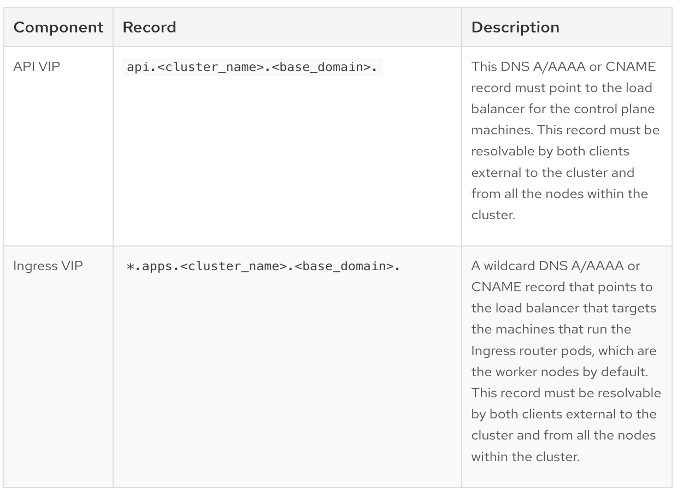
Note: Screenshots of the DNS and DHCP setup from the Windows server are provided below.
Setup Information
Table 14. Red Hat OpenShift Deployment: Setup Information
| Parameter Type |
Parameter Name | Value |
Additional Information |
| OpenShift Installer machine |
10.120.1.225 |
|
| IP subnet for OpenShift Cluster |
10.120.2.0/24 |
|
| Default Gateway IP |
10.120.2.254 |
|
| NTP |
172.20.10.120 |
Add two NTP sources for redundancy |
| DNS Server |
10.120.1.240 |
Windows AD server used in this CVD |
| DHCP Server |
10.120.1.240 |
Windows AD server used in this CVD |
| Red Hat OpenShift Cluster: DNS Setup |
||
| Base Domain |
fpb.local |
|
| OpenShift Cluster Name |
ac10-ocp |
|
| API VIP |
api.ac10-ocp.fpb.local |
10.120.2.250 |
| Ingress VIP |
*.apps.ac10-ocp.fpb.local |
10.120.2.253 |
| Red Hat OpenShift Cluster: DHCP Setup |
||
| Control/Worker Nodes: In-Band Management |
10.120.1.[1-16]/24 |
vNIC: eno5 |
| Control/Worker Nodes: OpenShift Cluster Management |
10.120.2.[1-16]/24 |
vNIC: eno6 |
| Worker Nodes: iSCSI-A |
192.168.15.[1-16]/24 |
vNIC: eno7 |
| Worker Nodes: iSCSI-B |
192.168.25.[1-16]/24 |
vNIC: eno8 |
| Worker Nodes: NVMe-TCP-A |
192.168.35.[1-16]/24 |
vNIC: eno7 |
| Worker Nodes: NVMe-TCP-B |
192.168.45.[1-16]/24 |
vNIC: eno8 |
| Worker Nodes: NFS |
192.168.55.[1-16]/24 |
vNIC: eno9 |
| Worker Nodes: S3-OBJ |
10.120.9.[1-16]/24 |
vNIC: eno10 |
| NetApp Storage: Storage |
||
| NVMe-iSCSI-A LIFs |
192.168.15.[.51-.52] |
|
| NVMe-iSCSI-B LIFs |
192.168.25.[.51-.52] |
|
| NVMe-TCP-A LIFs |
192.168.35.[.51-.52] |
|
| NVMe-TCP-B LIFs |
192.168.45.[.51-.52] |
|
| NVMe-NFS LIFs |
192.168.55.[.51-.52] |
|
| NVMe-S3-OBJ LIFs |
10.120.9.[.51-.52] |
|
Deployment Steps – Setup Prerequisites
This section details the prerequisite setup to install Openshift cluster.
Procedure 1. Deploy Installer workstation to manage the OpenShift cluster
Step 1. Deploy a workstation with Linux (for example, Rocky Linux, RHEL) to manage the Openshift cluster using CLI.
Step 2. On the OpenShift Installer machine, create a new directory for storing all data related to the new cluster being deployed. For example: ocp-ac10-cvd is used in this CVD.
Procedure 2. Enable SSH access to OpenShift cluster
Step 1. Go to the newly created directory and run the following commands to generate a SSH key pair to enable SSH access to the OpenShift cluste:.
Note: This must be done prior to cluster deployment. The commands you'll need are provided below. You can use either rsa or edcsa algorithm.
cd <new directory for cluster>
ssh-keygen -t rsa -N '' -f <path>/<file_name>
eval "$(ssh-agent -s)"
ssh-add <path>/<file_name>
[administrator@localhost ocp-ac10-cvd]$ssh-keygen -t rsa -N '' -f ~/.ssh/id_rsa
Generating public/private rsa key pair.
Your identification has been saved in /home/administrator/.ssh/id_rsa
Your public key has been saved in /home/administrator/.ssh/id_rsa.pub
The key fingerprint is:
SHA256:x77D3V9vkmFYbwG7pxPblXZ3bYxu8CSM4dHi0YlsUd4 administrator@localhost.localdomain
The key's randomart image is:
+---[RSA 3072]----+
| .. |
| .. o |
| . =..E |
| .O +... |
| S+oB o.++|
| o+ =o=+@|
| ... OB=*|
| o..+B.+|
| .. ..+o|
+----[SHA256]-----+
Step 2. Verify that the ssh-agent process is running and if not, start it as a background task by running the following:
[administrator@localhost ocp-ac10-cvd]$ eval "$(ssh-agent -s)"
Agent pid 1253935
[administrator@localhost ocp-ac10-cvd]$
Step 3. Add the SSH private key identity to the SSH agent for your local user.
[administrator@localhost ocp-ac10-cvd]$ ssh-add ~/.ssh/id_rsa
Identity added: /home/administrator/.ssh/id_rsa (administrator@localhost.localdomain)
[administrator@localhost ocp-ac10-cvd]$
Step 4. Assisted Installer adds the SSH keys to the ignition files that are used to do the initial configuration of the OpenShift nodes. Once the OpenShift cluster is deployed, you will be able to access the cluster as user core without the need for password.
Step 5. Verify the connectivity from OpenShift cluster subnet to all NTP sources.
Procedure 3. Add the DNS records for the OpenShift cluster’s API and Ingress VIP
Step 1. On the DNS server, create a domain (for example, ac10-ocp) and sub-domain (for example, apps) under the parent/base domain (for example, fpb.local).
For this CVD, the DNS service is enabled on a Windows AD server. The DNS configuration on this server for this cluster is shown below:
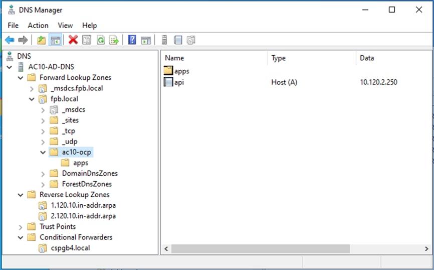
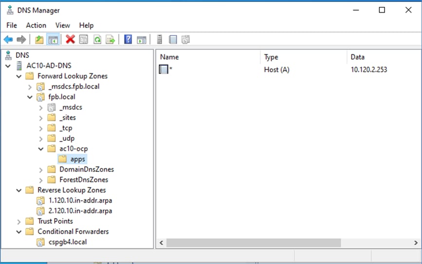
Procedure 4. Add DHCP Pools for various networks and configure the DHCP options for NTP, DNS, Gateway
Step 1. On the DHCP server, create DHCP scopes for OpenShift control and worker node subnets.
For this CVD, the DHCP service is enabled on a Windows AD server. The DHCP configuration on the server for this cluster is shown below:
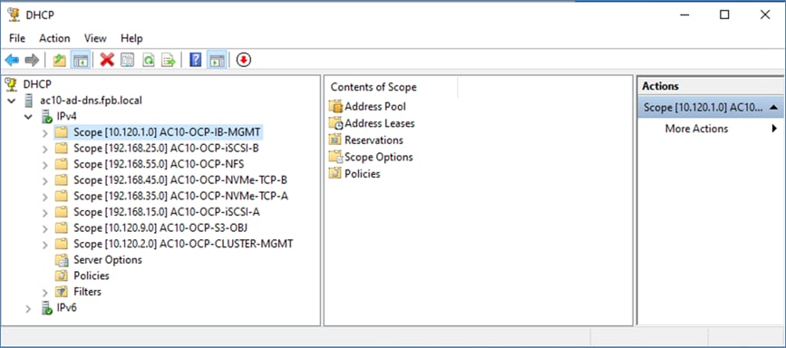
For each scope, the following DHCP options are configured:
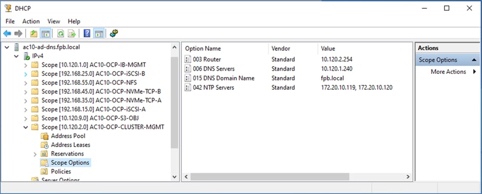
Deployment Steps – Install the OpenShift Cluster
This section details the post-deployment verification.
Procedure 1. Install OpenShift cluster using Assisted Installer from Red Hat Hybrid Cloud Console
Step 1. Use a web browser to go to console.redhat.com and log into your account.
Step 2. Go to Containers > Clusters.
Step 3. Go to the Red Hat OpenShift Container Platform (OCP) tile and click Create Cluster.
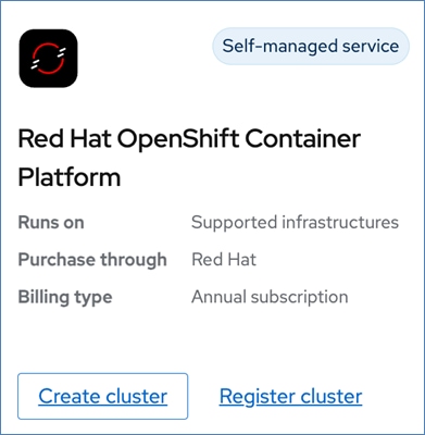
Step 4. Click the Datacenter tab.
Step 5. Choose Assisted Installer > Create Cluster. Alternatively, you can choose another infrastructure and installer option from the list below.
Step 6. For Cluster Details, provide the necessary inputs to the Assisted Installer as shown. Use the settings provided in Table 14.
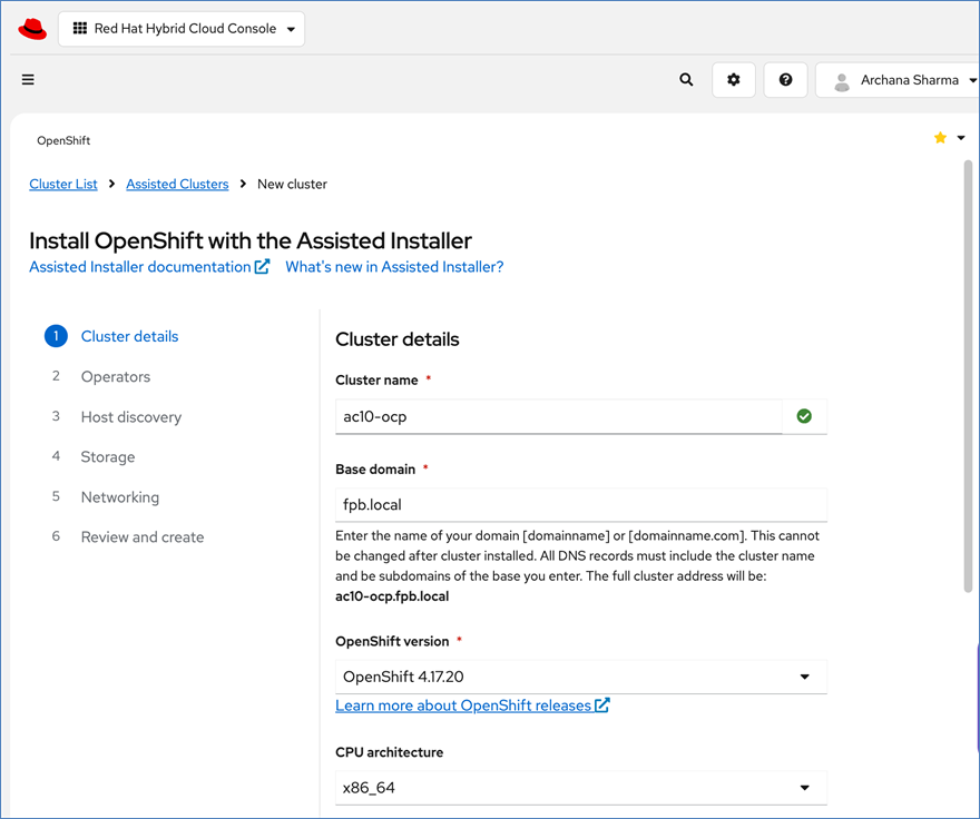
Step 7. Scroll down to the end of the page and choose the settings shown below:
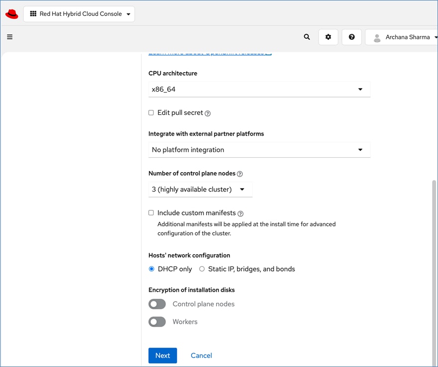
Step 8. Click Next.
Step 9. For Operators, skip all options.
Note: You will need to install several operators (for NVIDIA, NetApp storage, and OpenShift AI) but at the time of this writing, many of these are still in the developer preview stage, so you will deploy these once the cluster is deployed.
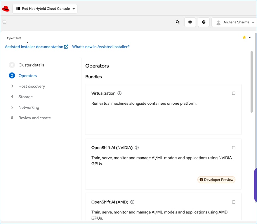
Step 10. Scroll-down to the end of the page.
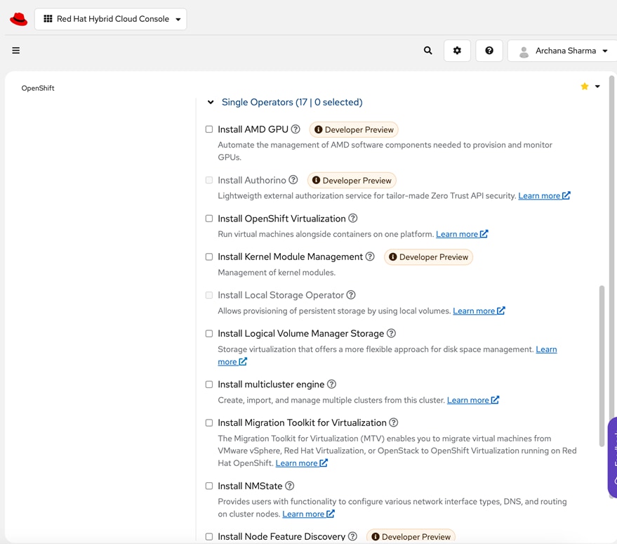
Step 11. Click Next.
Step 12. For Host Discovery, click Add Hosts.
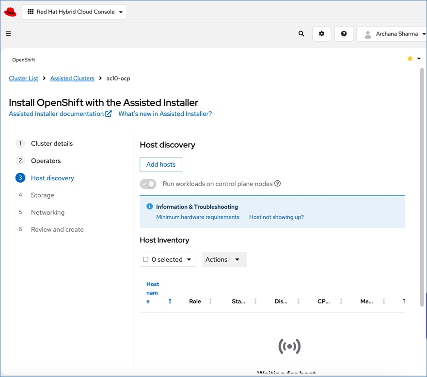
Step 13. In the Add Hosts pop-up window, for the Provisioning Type, choose Minimal Image File from the drop-down list.
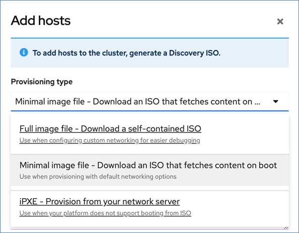
Step 14. For the SSH public key, upload the SSH keys previously generated on the Installer workstation. Keep the default settings.
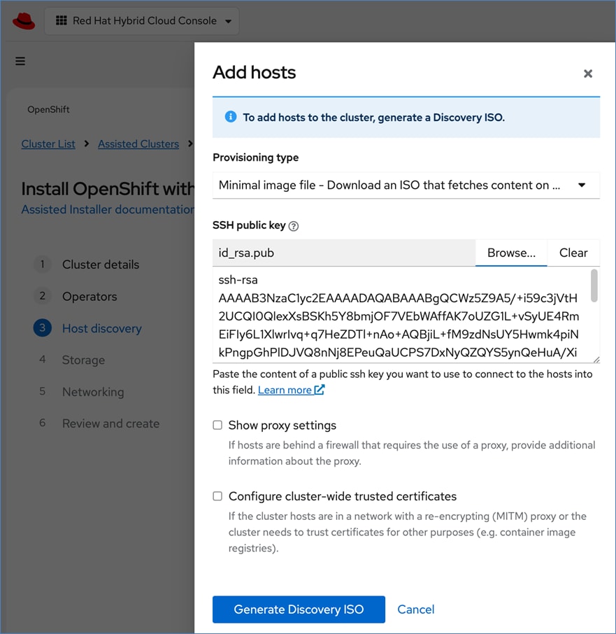
Step 15. Click Generate Discovery ISO.
Step 16. In the Add hosts window, click Add Hosts from Cisco Intersight, to select and deploy the Discovery ISO on the selected servers to start the installation process.

Step 17. Now you will be directed to Cisco Intersight. Log in using the account where the servers were deployed.
After you log in, you will see the Execute Workflow: Boot Servers from ISO URL window:
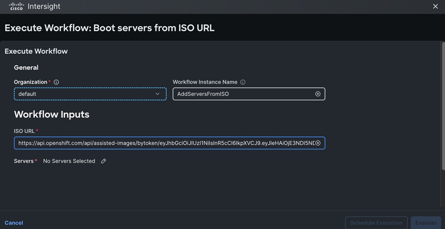
Step 18. For Organization, choose the Intersight organization for the UCS servers (for example, FPB-OAI).
Step 19. For Servers, click No Servers Selected and choose from the list of available servers.
Step 20. Click Save.
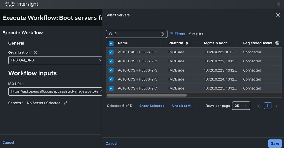
Step 21. Click Execute to initiate the download of the Discovery ISOs to the list of servers that will form the OpenShift cluster with control and worker nodes.

The following screenshot displays showing that the workflow was triggered:
Step 22. Click the Requests icon to monitor the booting of the UCS servers using the discovery ISO provided Assisted Installer running on the Hybrid Cloud Console.
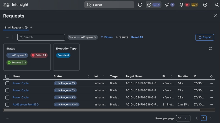
Step 23. When the process completes (~5 minutes), return to the Hybrid Cloud Console and Assisted Installer.
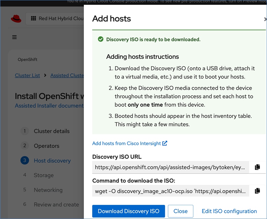
Step 24. Click Close.
You will see the nodes show up one by one in the Assisted Installer under Host Discovery > Host Inventory.
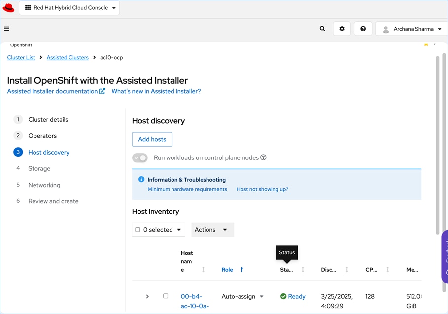
Step 25. Wait for all nodes to display. This may take several minutes.
Step 26. Click View Cluster events to view the activities.
Step 27. Click Next.
When all five servers have booted from the Discovery ISO, they will appear in the Assisted Installer:
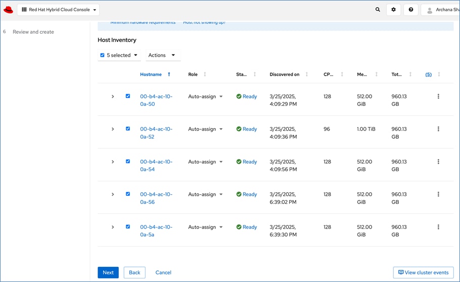
Step 28. For each server, under Role, from the drop-down list choose whether it is a control plane node or a worker node.
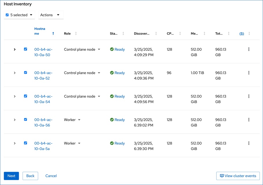
Step 29. Edit the hostname of each node by clicking the current hostname.
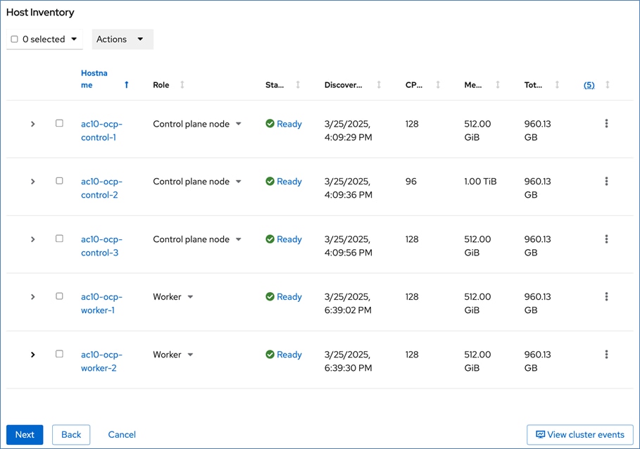
Step 30. Expand each node and verify NTP is synced.
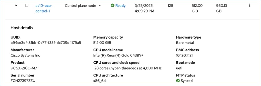
Step 31. Scroll down and click Next.
Step 32. Expand each node and confirm the role of the M.2 disk is set to Installation disk.
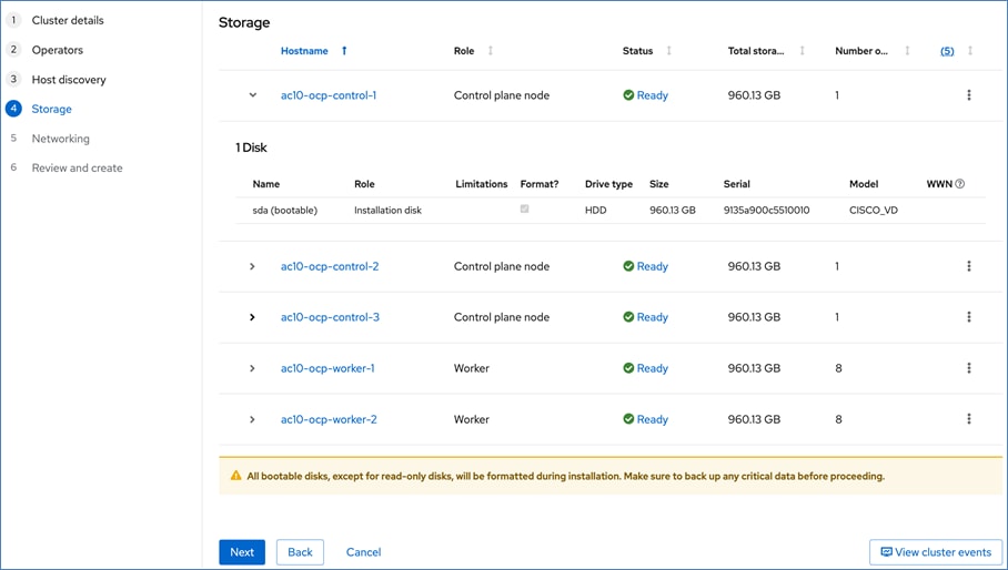
Step 33. Click Next.
Step 34. For Networking, choose Cluster-Managed Networking. For Machine network, choose the OpenShift cluster management subnet from the drop-down list. Specify the API and Ingress IP in the corresponding fields.
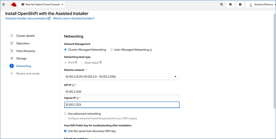
Step 35. Scroll down and check that all nodes have a Ready status.
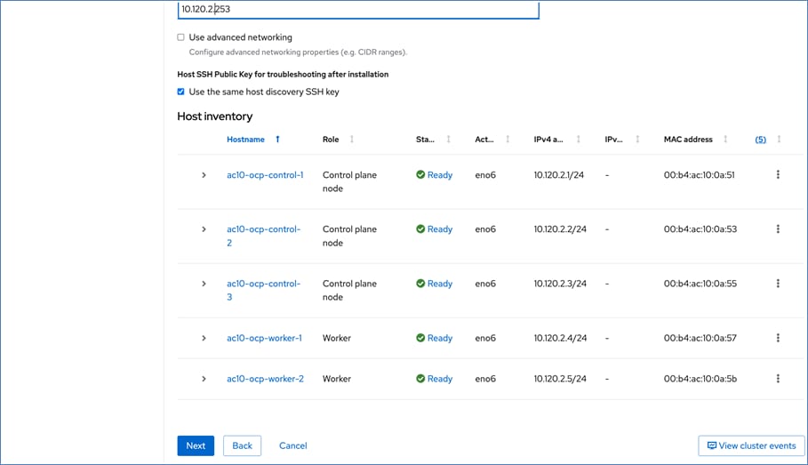
Step 36. When all nodes are in a Ready status, click Next.
Step 37. Review the information.
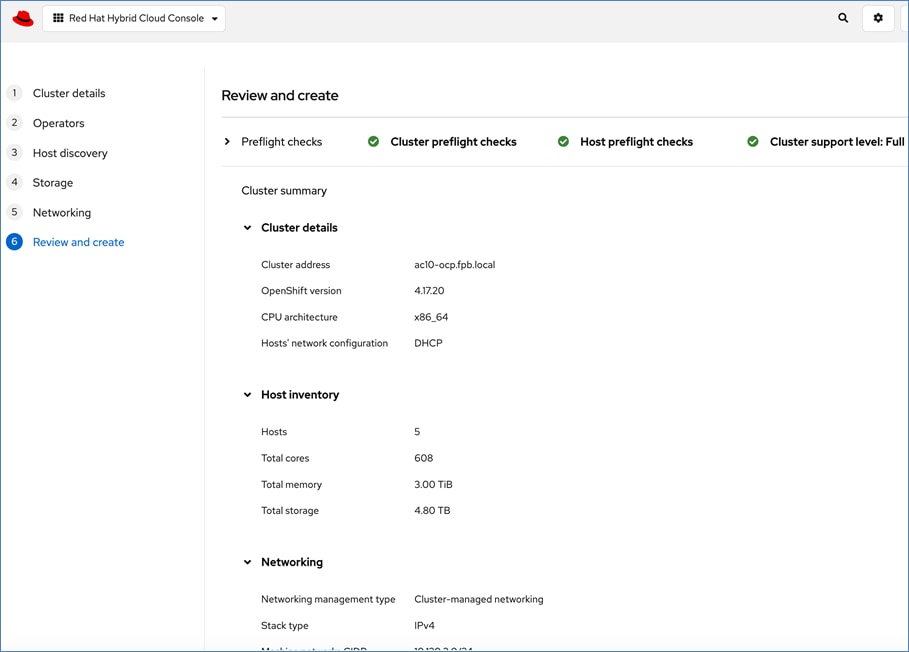
Step 38. Click Install cluster to begin the cluster installation.
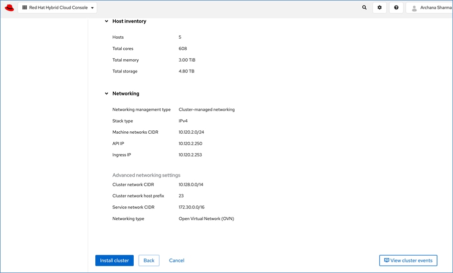
Step 39. On the Installation progress page, expand the Host inventory. The installation will take 30-45 minutes.
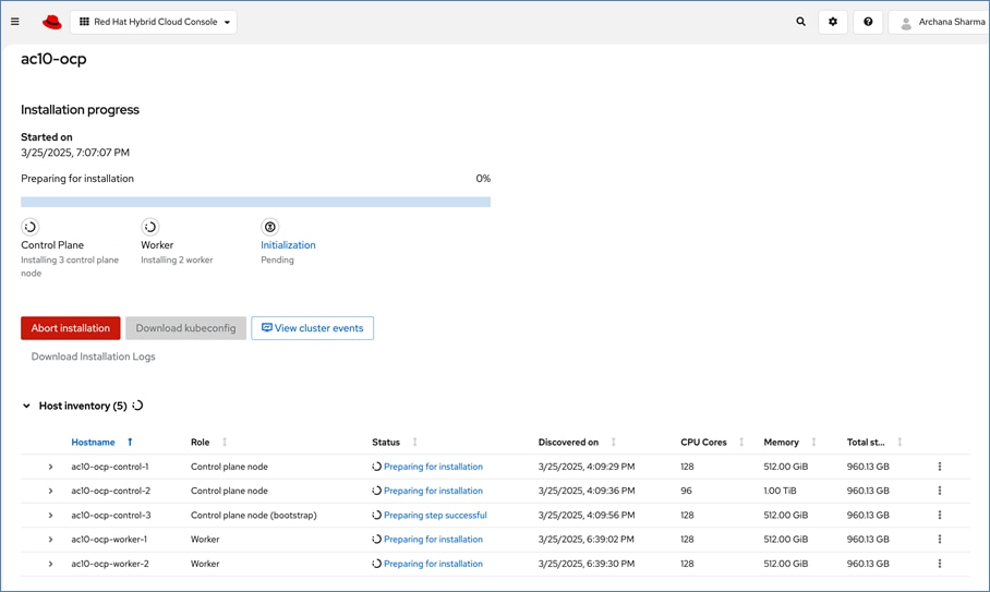
When the installation is complete, the status of all nodes display as completed.
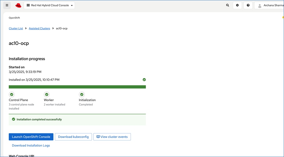
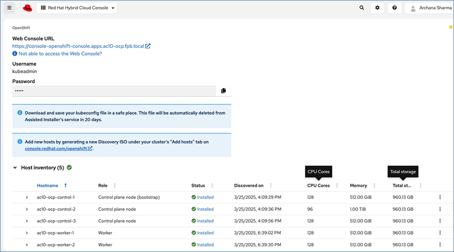
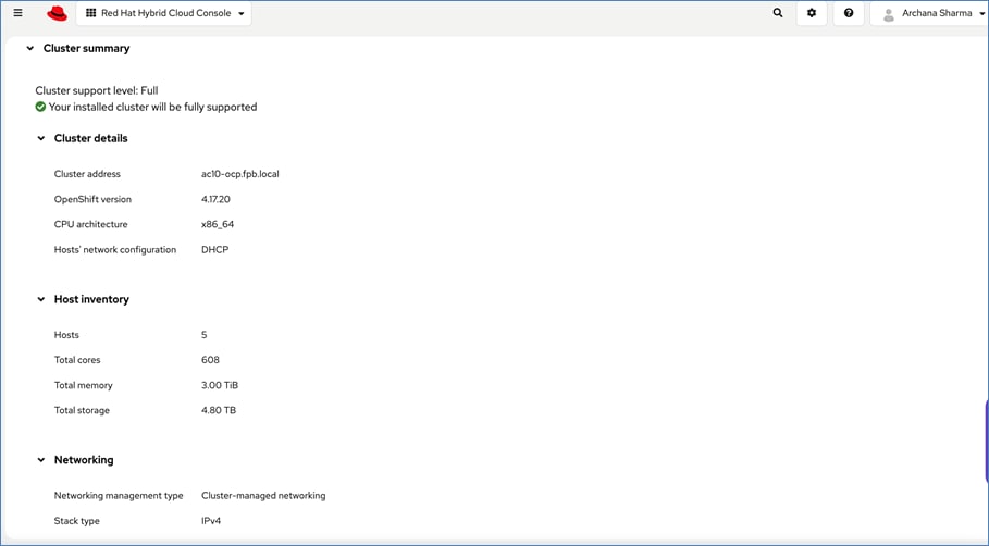
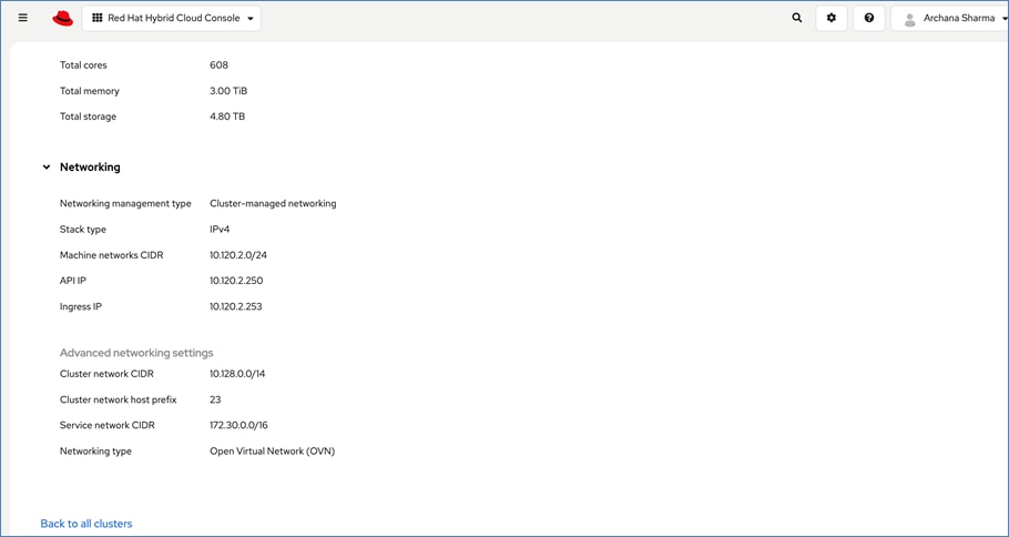
You can expand a node and verify its configuration as shown below. For example, interface names, speeds, DHCP provided IP addresses and GPU specific information, such as the GPU model and Vendor:
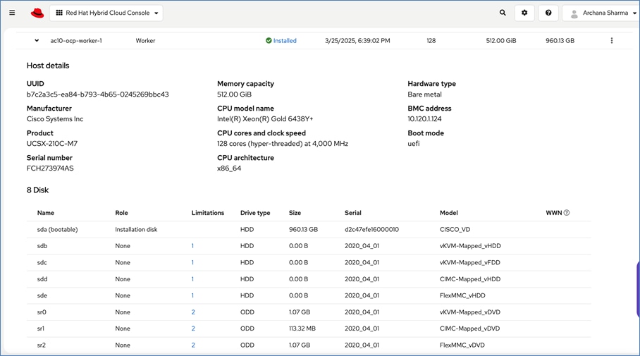
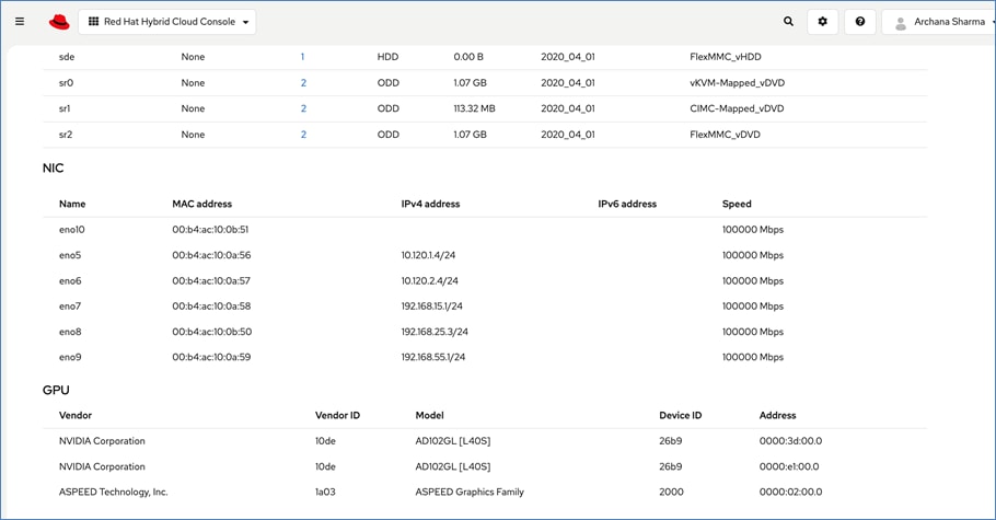
Deployment Steps – Post-Deployment
This section details the post-deployment steps and other verifications required.
Procedure 1. Download and save the kubeconfig and kubeadmin password from the Red Hat Hybrid Cloud Console
Step 1. When the install is complete, download and save the kubeconfig file in a safe location as instructed.
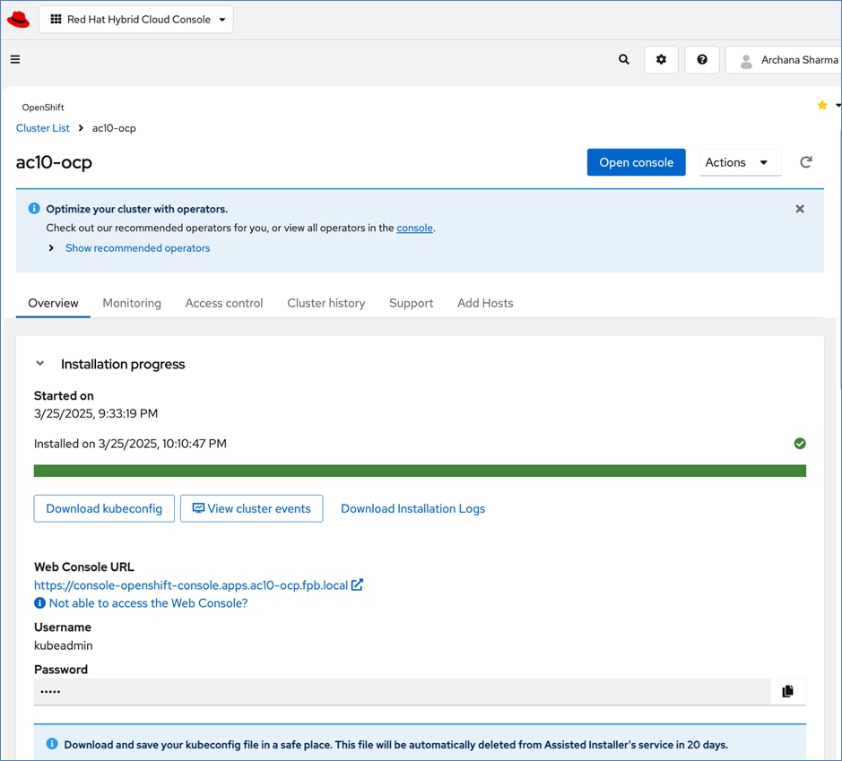
Step 2. To download the kubeconfig file, click Download kubeconfig. Copy the file (if needed) to the OpenShift Installer machine and save it in the location specified in the next step.
Step 3. On the installer machine, in a terminal window, after you’ve downloaded the file to the installer machine, run the following commands to copy the file (from Downloads) to the location in the cluster directory as specified:
[administrator@localhost Downloads]$ ls
kubeconfig
[administrator@localhost Downloads]$ pwd
/home/administrator/Downloads
[administrator@localhost Downloads]$ ls
kubeconfig
[administrator@localhost Downloads]$ cd ..
[administrator@localhost ~]$ cd FPB/
ac10-ocp/ ocp-ac10-cvd/
[administrator@localhost ~]$ cd FPB/ocp-ac10-cvd/
[administrator@localhost ocp-ac10-cvd]$ ls
[administrator@localhost ocp-ac10-cvd]$ mkdir auth
[administrator@localhost ocp-ac10-cvd]$ cd auth
[administrator@localhost auth]$ mv ~/Do
Documents/ Downloads/
[administrator@localhost auth]$ mv ~/Downloads/kubeconfig ./
[administrator@localhost auth]$ ls
Kubeconfig
[administrator@localhost ~]$ mkdir ~/.kube
[administrator@localhost auth]$ cp kubeconfig ~/.kube/config
Step 4. Return to the Assisted Installer cluster installation page on Red Hat Hybrid Cloud Console and click the icon next to kubeadmin password to copy the password.
Step 5. On the installer machine, in a terminal window, run the following commands to copy and save the kubeadmin password in a location specified below:
echo <paste password> > ./kubeadmin-password
Procedure 2. Download kubeconfig, kubeadmin password, and oc tools
Step 1. Return to the Assisted Installer cluster installation page on Red Hat Hybrid Cloud Console and click or copy the Web Console URL and go to the URL to launch the OpenShift Console for the newly deployed cluster. Log in using the kubeadmin and the kubeadmin password.
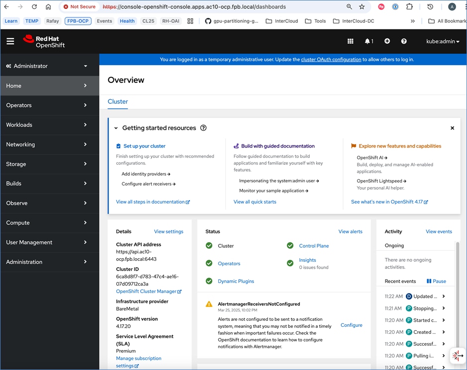
Step 2. Click the ? icon and choose Command Line Tools from the drop-down list. Links for various tools are provided in this page.
Step 3. Click Download oc for Linux for x86_64.
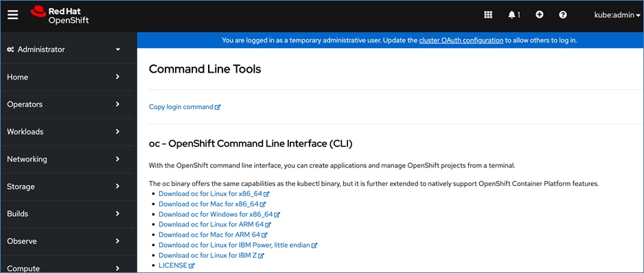
Step 4. Copy the file (if needed) to the OpenShift Installer machine and save it in the cluster directory location as specified below:
[administrator@localhost FPB]$ cd ocp-ac10-cvd/
[administrator@localhost ocp-ac10-cvd]$ ls
auth
[administrator@localhost ocp-ac10-cvd]$ mkdir client
[administrator@localhost ocp-ac10-cvd]$ cd client
[administrator@localhost client]$ ls ~/Downloads/
oc.tar
[administrator@localhost client]$ mv ~/Downloads/oc.tar ./
[administrator@localhost client]$ tar xvf oc.tar
oc
[administrator@localhost client]$ ls
oc oc.tar
[administrator@localhost client]$ sudo mv oc /usr/local/bin
[sudo] password for administrator:
Sorry, try again.
[sudo] password for administrator:
[administrator@localhost client]$ oc get nodes
NAME STATUS ROLES AGE VERSION
ac10-ocp-control-1 Ready control-plane,master 13h v1.30.10
ac10-ocp-control-2 Ready control-plane,master 13h v1.30.10
ac10-ocp-control-3 Ready control-plane,master 13h v1.30.10
ac10-ocp-worker-1 Ready worker 13h v1.30.10
ac10-ocp-worker-2 Ready worker 13h v1.30.10
[administrator@localhost client]$
Step 5. To enable oc tab completion for bash, run the following:
[administrator@localhost client]$ oc completion bash > oc_bash_completion
[administrator@localhost client]$ sudo mv oc_bash_completion /etc/bash_completion.d/
[administrator@localhost client]$
Procedure 3. Set up Power Management for Bare Metal Hosts
Step 1. Log into the OpenShift Cluster Console.
Step 2. Go to Compute > Nodes to see the status of the OpenShift nodes.
Step 3. In the Red Hat OpenShift console, click Compute > Bare Metal Hosts.
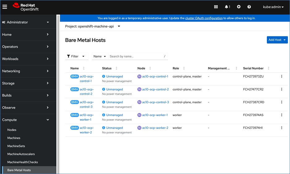
Step 4. For each Bare Metal Host, click the elipses and choose Edit Bare Metal Host and check the box to Enable power management.
Note: If you’re using a dedicated network for managing the hosts out-of-band, specify the mac address for that interface, here so it can be used for Power Management. You will also need to provide the username and password that was previously provisioned for IPMI access from Cisco Intersight.
Step 5. Click Save.
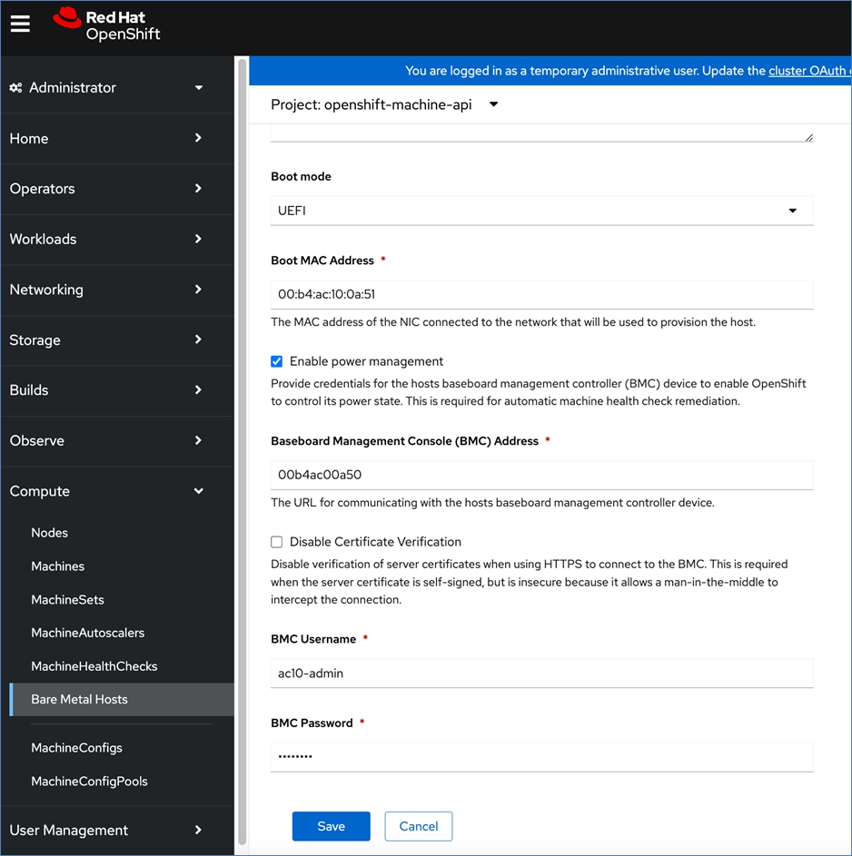
Step 6. Repeat steps 1 - 5 for all baremetal hosts in the cluster.
Note: When all hosts have been configured, the status displays as Externally Provisioned and the Management Address is populated. Now you can manage the power on the OpenShift hosts from the OpenShift console.
Note: For an IPMI connection to the server, use the BMC IP address. However, for Redfish to connect to the server, use this format for the BMC address; redfish:///redfish/v1/Systems/ and make sure to check Disable Certificate Verification.
Procedure 4. (Optional) Reserve Resources for System Components
Note: It is recommended to reserve enough resources ( cpus and memory) for system components like kubelet and kube-proxy on the nodes. OpenShift Container Platform can automatically determine the optimal system-reserved CPU and memory resources for nodes associated with a specific machine config pool and update the nodes with those values when the nodes start. To automatically determine and allocate the system-reserved resources on nodes, create a KubeletConfig custom resource (CR) to set the autoSizingReserved: true parameter and apply the machine configuration files as outlined below.
Step 1. Log into the OpenShift Cluster console.
Step 2. Click the + to generate the following YAML file with the necessary configuration for worker nodes:
apiVersion: machineconfiguration.openshift.io/v1
kind: KubeletConfig
metadata:
name: dynamic-node
spec:
autoSizingReserved: true
machineConfigPoolSelector:
matchLabels:
pools.operator.machineconfiguration.openshift.io/worker: ""
Step 3. Click Create.
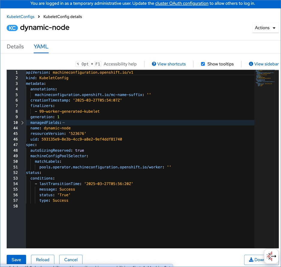
Step 4. Repeat steps 1 and 2 for control node and then run the following:
apiVersion: machineconfiguration.openshift.io/v1
kind: KubeletConfig
metadata:
name: dynamic-node-control-plane
spec:
autoSizingReserved: true
machineConfigPoolSelector:
matchLabels:
pools.operator.machineconfiguration.openshift.io/master: ""
Step 5. Click Create.
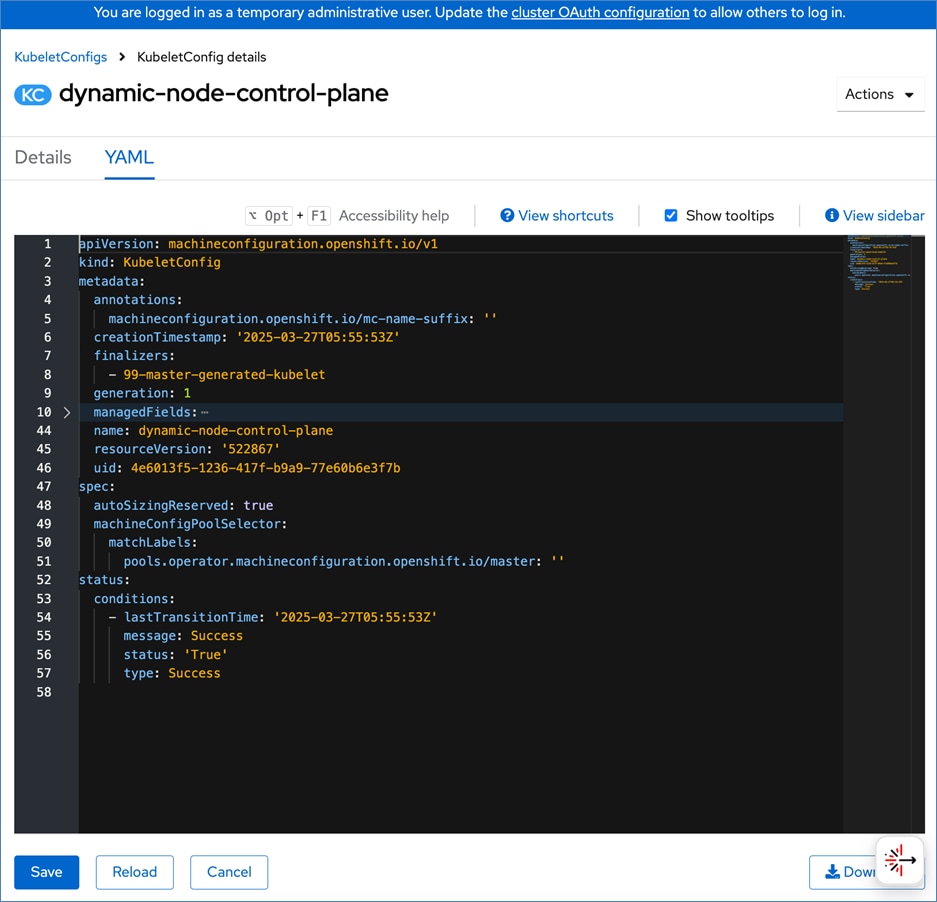
Procedure 5. Setup NTP on control-plane and worker nodes
Step 1. Log into the OpenShift Installer machine and create a new directory for storing machine configs in the previously created cluster directory as shown below:
mkdir machine-configs
cd machine-configs
curl https://mirror.openshift.com/pub/openshift-v4/clients/butane/latest/butane --output butane
chmod +x butane
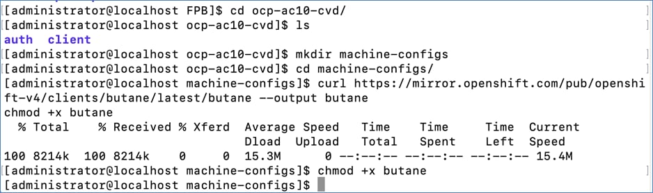
Step 2. Create the following files in the machine-configs directory with the correct NTP Ips:
File: 99-control-plane-chrony-conf-override.bu
variant: openshift
version: 4.16.0
metadata:
name: 99-control-plane-chrony-conf-override
labels:
machineconfiguration.openshift.io/role: master
storage:
files:
- path: /etc/chrony.conf
mode: 0644
overwrite: true
contents:
inline: |
driftfile /var/lib/chrony/drift
makestep 1.0 3
rtcsync
logdir /var/log/chrony
server 172.20.10.120 iburst
File: 99-worker-chrony-conf-override.bu
variant: openshift
version: 4.16.0
metadata:
name: 99-worker-chrony-conf-override
labels:
machineconfiguration.openshift.io/role: worker
storage:
files:
- path: /etc/chrony.conf
mode: 0644
overwrite: true
contents:
inline: |
driftfile /var/lib/chrony/drift
makestep 1.0 3
rtcsync
logdir /var/log/chrony
server 172.20.10.120 iburst
Step 3. Create the .yaml files from the butane files with butane:
./butane 99-control-plane-chrony-conf-override.bu -o ./99-control-plane-chrony-conf-override.yaml
./butane 99-worker-chrony-conf-override.bu -o ./99-worker-chrony-conf-override.yaml
Step 4. Apply the configuration to the OpenShift cluster:
oc create -f 99-control-plane-chrony-conf-override.yaml
oc create -f 99-worker-chrony-conf-override.yaml
Deployment Steps – Setup Storage interfaces on Kubernetes Nodes
This section details the following:
● Setup networking for accessing storage using iSCSI – enable iSCSI multipathing
● Setup networking for accessing storage using NVMe-TCP
● Setup networking for accessing storage using NFS
● Setup networking for accessing storage using S3-compatible Object Store
● Verify that the NetApp array is reachable from worker nodes on the storage access methods
To setup the storage interfaces on Kubernetes nodes to access the NetApp storage using access iSCSI, NVMe-TCP, and NFS storage, complete the following procedures.
Procedure 1. Setup iSCSI Multipathing on iSCSI interfaces
Step 1. Create the following YAML configuration file to enable iSCSI multipathing:
[administrator@localhost machine-configs]$
[administrator@localhost machine-configs]$ cat 99-worker-iscsi-multipathing.yaml
apiVersion: machineconfiguration.openshift.io/v1
kind: MachineConfig
metadata:
name: 99-worker-ontap-iscsi
labels:
machineconfiguration.openshift.io/role: worker
spec:
config:
ignition:
version: 3.2.0
storage:
files:
- contents:
source: data:text/plain;charset=utf-8;base64,IyBkZXZpY2UtbWFwcGVyLW11bHRpcGF0aCBjb25maWd1cmF0aW9uIGZpbGUKCiMgRm9yIGEgY29tcGxldGUgbGlzdCBvZiB0aGUgZGVmYXVsdCBjb25maWd1cmF0aW9uIHZhbHVlcywgcnVuIGVpdGhlcjoKIyAjIG11bHRpcGF0aCAtdAojIG9yCiMgIyBtdWx0aXBhdGhkIHNob3cgY29uZmlnCgojIEZvciBhIGxpc3Qgb2YgY29uZmlndXJhdGlvbiBvcHRpb25zIHdpdGggZGVzY3JpcHRpb25zLCBzZWUgdGhlCiMgbXVsdGlwYXRoLmNvbmYgbWFuIHBhZ2UuCgpkZWZhdWx0cyB7Cgl1c2VyX2ZyaWVuZGx5X25hbWVzIHllcwoJZmluZF9tdWx0aXBhdGhzIG5vCn0KCmJsYWNrbGlzdCB7Cn0K
verification: {}
filesystem: root
mode: 600
overwrite: true
path: /etc/multipath.conf
systemd:
units:
- name: iscsid.service
enabled: true
state: started
- name: multipathd.service
enabled: true
state: started
osImageURL: ""
[administrator@localhost machine-configs]$
Step 2. Apply the configuration:
oc create -f 99-worker-iscsi-multipathing.yaml
Procedure 2. Configure the worker node interface to enable the NVMe-TCP Path A interface
Step 1. Run the following configuration file to configure the NVMe-TCP-A interface – it will be a tagged VLAN on the iSCSI-A interface.
[administrator@localhost machine-configs]$ more 99-worker-eno7-3035.bu
variant: openshift
version: 4.17.0
metadata:
name: 99-worker-eno7-3035
labels:
machineconfiguration.openshift.io/role: worker
storage:
files:
- path: /etc/NetworkManager/system-connections/eno7-3035.nmconnection
mode: 0600
overwrite: true
contents:
inline: |
[connection]
id=eno7-3035
type=vlan
interface-name=eno7-3035
[ethernet]
[vlan]
flags=1
id=3035
parent=eno7
[ipv4]
method=auto
[ipv6]
addr-gen-mode=default
method=disabled
[proxy]
[administrator@localhost machine-configs]$
Step 2. Convert the configuration files to .yaml format:
./butane 99-worker-eno7-3035.bu -o ./99-worker-eno7-3035.yaml
Step 3. Apply the configuration:
oc create -f 99-worker-eno7-3035.bu
Procedure 3. Configure the worker node interface to enable the NVMe-TCP Path B interface
Step 1. Run the following configuration file to configure the NVMe-TCP-B interface – it will be a tagged VLAN on the iSCSI-B interface.
[administrator@localhost machine-configs]$ more 99-worker-eno8-3045.bu
variant: openshift
version: 4.17.0
metadata:
name: 99-worker-eno8-3045
labels:
machineconfiguration.openshift.io/role: worker
storage:
files:
- path: /etc/NetworkManager/system-connections/eno8-3045.nmconnection
mode: 0600
overwrite: true
contents:
inline: |
[connection]
id=eno8-3045
type=vlan
interface-name=eno8-3045
[ethernet]
[vlan]
flags=1
id=3045
parent=eno8
[ipv4]
method=auto
[ipv6]
addr-gen-mode=default
method=disabled
[proxy]
[administrator@localhost machine-configs]$
Convert the configuration files to .yaml format.
./butane 99-worker-eno8-3045.bu -o ./99-worker-eno8-3045.yaml
Apply the configuration.
oc create -f 99-worker-eno8-3045.yaml
Procedure 4. Enable NVMe-TCP discovery
Step 1. Enable NVMe-TCP discovery – it uses the previously configured interfaces:
[administrator@localhost machine-configs]$ more 99-worker-nvme-discovery.bu
variant: openshift
version: 4.17.0
metadata:
name: 99-worker-nvme-discovery
labels:
machineconfiguration.openshift.io/role: worker
openshift:
kernel_arguments:
- loglevel=7
storage:
files:
- path: /etc/nvme/discovery.conf
mode: 0644
overwrite: true
contents
inline: |
--transport=tcp --traddr=192.168.35.51 --trsvcid=8009
--transport=tcp --traddr=192.168.45.52 --trsvcid=8009
[administrator@localhost machine-configs]$
Step 2. Convert the configuration files to .yaml format:
./butane 99-worker-nvme-discovery.bu -o ./99-worker-nvme-discovery.yaml
Step 3. Apply the configuration:
oc create -f 99-worker-nvme-discovery.yaml
Procedure 5. Configure the worker node interface to enable NFS storage access
Step 1. Run the following configuration file to configure the NFS interface:
[administrator@localhost machine-configs]$ more 99-worker-eno9.bu
variant: openshift
version: 4.17.0
metadata:
name: 99-worker-eno9
labels:
machineconfiguration.openshift.io/role: worker
storage:
files:
- path: /etc/NetworkManager/system-connections/eno9.nmconnection
mode: 0600
overwrite: true
contents:
inline: |
[connection]
id=eno9
type=ethernet
interface-name=eno9
[ethernet]
[ipv4]
method=auto
[ipv6]
addr-gen-mode=default
method=disabled
[proxy]
[user]
[administrator@localhost machine-configs]$
Step 2. Convert the configuration files to .yaml format:
./butane 99-worker-eno9.bu -o ./99-worker-eno9.yaml
Step 3. Apply the configuration:
oc create -f 99-worker-eno9.yaml
Procedure 6. Configure the worker node interface to enable the S3 Object storage access
Step 1. Run the following configuration file to configure S3 Object interface:
[administrator@localhost machine-configs]$ more 99-worker-eno10.bu
variant: openshift
version: 4.17.0
metadata:
name: 99-worker-eno10
labels:
machineconfiguration.openshift.io/role: worker
storage:
files:
- path: /etc/NetworkManager/system-connections/eno10.nmconnection
mode: 0600
overwrite: true
contents:
inline: |
[connection]
id=eno10
type=ethernet
interface-name=eno10
[ethernet]
[ipv4]
method=auto
[ipv6]
addr-gen-mode=default
method=disabled
[proxy]
[user]
[administrator@localhost machine-configs]$
Step 2. Convert the configuration files to .yaml format:
./butane 99-worker-eno9.bu -o ./99-worker-eno9.yaml
Step 3. Apply the configuration:
oc create -f 99-worker-eno9.yaml
Step 4. Over the next 10-20 minutes each of the nodes will go through the “Not Ready” state and reboot. You can monitor this by going to Compute > MachineConfigPools in the OCP Console.
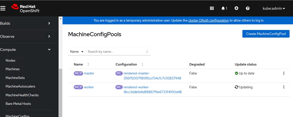
Procedure 7. Verify the connectivity to NetApp Storage
Step 1. From the OpenShift installer machine, SSH into the first worker node.
Step 2. For each storage access interface, verify connectivity to NetApp storage by pinging the LIFs.
Step 3. Repeat step 1 and 2 for each worker node.
Deploy NetApp Trident Operator
NetApp Trident is an open-source, fully supported storage orchestrator for containers and Kubernetes distributions. It was designed to help meet the containerized applications’ persistence demands using industry-standard interfaces, such as the Container Storage Interface (CSI). With Trident, microservices and containerized applications can take advantage of enterprise-class storage services provided by the NetApp portfolio of storage systems. More information about Trident can be found here: NetApp Trident Documentation. There are various methods to install NetApp Trident. In this solution, we will cover the installation of NetApp Trident version 25.2.0 using the Trident Operator, which is installed using OperatorHub.
The Trident Operator is designed to manage the lifecycle of Trident. It streamlines the deployment, configuration, and management processes. The Trident Operator is compatible with OpenShift version 4.10 and later.
Procedure 1. Install the NetApp Trident Operator from OpenShift Operator Hub
Step 1. Log into the OCP web console and create a project with the name trident.
Step 2. Go to Operators > OperatorHub.
Step 3. Type Trident in the filter box and click Certified NetApp Trident Operator.
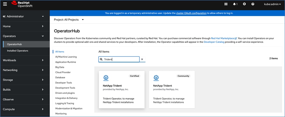
Step 4. Click Install.
Step 5. For Update Approval, choose Manual.
Step 6. For Installed Namespace, click Create project and specify project name as trident.
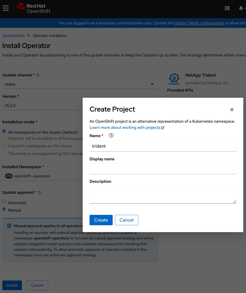
Step 7. Click Create.
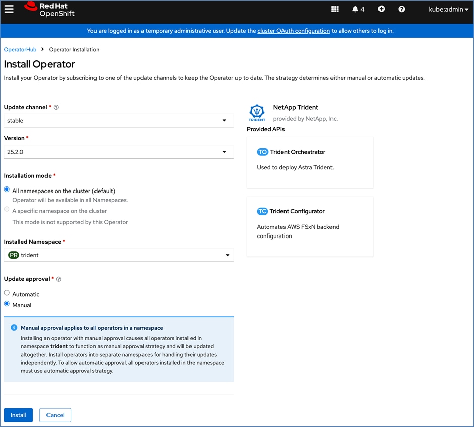
Step 8. Click Install.
Step 9. Click Approve.
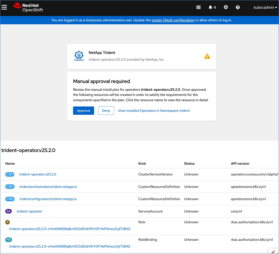
Step 10. Wait for the installation to complete. Verify the installation completes successfully.
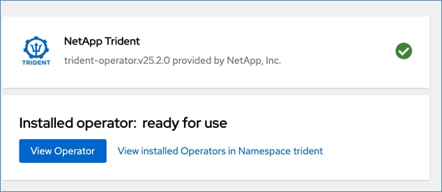
Step 11. Click View Operator.
Step 12. Go to Trident Orchestrator.
Step 13. Click Create TridentOrchestrator.
Step 14. Click Create.
Step 15. Wait for the Status to become Installed.
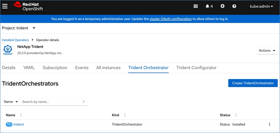
Step 16. SSH into the installer machine and verify the status of the Trident pods. All pods should be running.
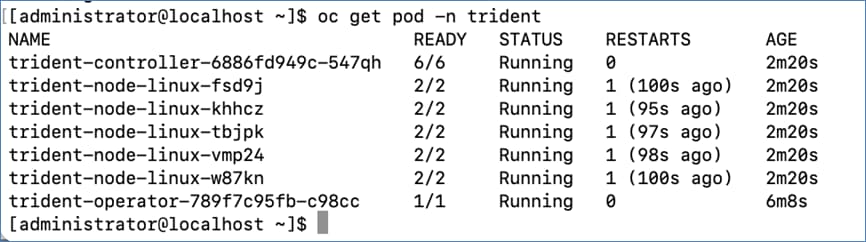
Procedure 2. Get Trident Utility Tool
Step 1. Create a directory on the management VM, then download and untar the file to obtain trident-installer folder:
mkdir trident
cd trident
wget https://github.com/NetApp/trident/releases/download/v25.02.0/trident-installer-25.02.0.tar.gz
tar xvzf trident-installer-25.02.0.tar.gz
Step 2. Copy tridentctl to /usr/local/bin:
sudo cp trident-installer/tridentctl /bin/
Step 3. Verify the trident version:
[administrator@localhost ~]$ tridentctl -n trident version
+----------------+----------------+
| SERVER VERSION | CLIENT VERSION |
+----------------+----------------+
| 25.02.0 | 25.02.0 |
+----------------+----------------+
Note: Before configuring the backends that Trident needs to use for user apps, go to: https://docs.netapp.com/us-en/trident/trident-reference/objects.html#kubernetes-customresourcedefinition-objects to understand the storage environment parameters and its usage in Trident.
Procedure 3. Configure the Storage Backends in Trident
Step 1. Configure the connections to the SVM on the NetApp storage array created for the OpenShift installation. For more options regarding storage backend configuration, go to https://docs.netapp.com/us-en/trident/trident-use/backends.html.
Step 2. Create a backends directory and create the following backend definition files in that directory:
cat backend_NFS.yaml
---
version: 1
storageDriverName: ontap-nas
backendName: ocp-nfs-backend
managementLIF: 10.120.1.50
dataLIF: 192.168.55.51
svm: AC10-OCP-SVM
username: vsadmin
password: <password>
useREST: true
defaults:
spaceReserve: none
exportPolicy: default
snapshotPolicy: default
snapshotReserve: '10'
cat backend_NFS_flexgroup.yaml
---
version: 1
storageDriverName: ontap-nas-flexgroup
backendName: ocp-nfs-flexgroup
managementLIF: 10.120.1.50
dataLIF: 192.168.55.52
svm: AC10-OCP-SVM
username: vsadmin
password: <password>
useREST: true
defaults:
spaceReserve: none
exportPolicy: default
snapshotPolicy: default
snapshotReserve: '10'
cat backend_iSCSI.yaml
---
version: 1
storageDriverName: ontap-san
backendName: ocp-iscsi-backend
managementLIF: 10.120.1.50
svm: AC10-OCP-SVM
sanType: iscsi
useREST: true
username: vsadmin
password: <password>
defaults:
spaceReserve: none
spaceAllocation: 'false'
snapshotPolicy: default
snapshotReserve: '10'
cat backend_NVMe_TCP.yaml
---
version: 1
backendName: ocp-nvme-backend
storageDriverName: ontap-san
managementLIF: 10.120.1.50
svm: AC10-OCP-SVM
username: vsadmin
password: <password>
sanType: nvme
useREST: true
defaults:
spaceReserve: none
snapshotPolicy: default
snapshotReserve: '10'
Step 3. Create the storage backends for all storage protocols in your FlexPod:
tridentctl -n trident create backend -f backend_NFS.yaml
tridentctl -n trident create backend -f backend_NFS_flexgroup.yaml
tridentctl -n trident create backend -f backend_iSCSI.yaml
tridentctl -n trident create backend -f backend_NVMe_TCP.yaml
[administrator@localhost ~]$ tridentctl get backend -n trident
+-------------------+---------------------+--------------------------------------+--------+------------+---------+
| NAME | STORAGE DRIVER | UUID | STATE | USER-STATE | VOLUMES |
+-------------------+---------------------+--------------------------------------+--------+------------+-----
| ocp-nfs-flexgroup | ontap-nas-flexgroup | 87a36035-58c5-4638-a5d9-ff42cc4613d5 | online | normal | 0 |
| ocp-iscsi-backend | ontap-san | 68cf452a-9755-45f0-845f-a6909bc927a5 | online | normal | 0 |
| ocp-nvme-backend | ontap-san | e3e028cf-86d0-48e8-89db-4098f525bfe6 | online | normal | 0 |
| ocp-nfs-backend | ontap-nas | 57d378ed-3cab-45e5-89c9-877b04f81f09 | online | normal | 0 |
+-------------------+---------------------+--------------------------------------+--------+------------+----
Step 4. Create the following Storage Class files:
cat sc-ontap-nfs.yaml
---
apiVersion: storage.k8s.io/v1
kind: StorageClass
metadata:
name: ontap-nfs
annotations:
storageclass.kubernetes.io/is-default-class: "true"
provisioner: csi.trident.netapp.io
parameters:
backendType: "ontap-nas"
provisioningType: "thin"
snapshots: "true"
allowVolumeExpansion: true
cat sc-ontap-nfs-flexgroup.yaml
---
apiVersion: storage.k8s.io/v1
kind: StorageClass
metadata:
name: ontap-nfs-flexgroup
annotations:
storageclass.kubernetes.io/is-default-class: "false"
provisioner: csi.trident.netapp.io
parameters:
backendType: "ontap-nas-flexgroup"
provisioningType: "thin"
snapshots: "true"
allowVolumeExpansion: true
cat sc-ontap-iscsi.yaml
---
apiVersion: storage.k8s.io/v1
kind: StorageClass
metadata:
name: ontap-iscsi
parameters:
backendType: "ontap-san"
sanType: "iscsi"
provisioningType: "thin"
snapshots: "true"
allowVolumeExpansion: true
provisioner: csi.trident.netapp.io
cat sc-ontap-nvme.yaml
---
apiVersion: storage.k8s.io/v1
kind: StorageClass
metadata:
name: ontap-nvme-tcp
parameters:
backendType: "ontap-san"
sanType: "nvme"
provisioningType: "thin"
snapshots: "true"
allowVolumeExpansion: true
provisioner: csi.trident.netapp.io
Step 5. Create storage classes:
oc create -f sc-ontap-nfs.yaml
oc create -f sc-ontap-nfs-flexgroup.yaml
oc create -f sc-ontap-iscsi.yaml
oc create -f sc-ontap-nvme.yaml
Step 6. Verify the neylu created storage classes:
[administrator@localhost ~]$ oc get sc
NAME PROVISIONER RECLAIMPOLICY VOLUMEBINDINGMODE ALLOWVOLUMEEXPANSION AGE
ontap-iscsi csi.trident.netapp.io Delete Immediate true 12s
ontap-nfs (default) csi.trident.netapp.io Delete Immediate true 30s
ontap-nfs-flexgroup csi.trident.netapp.io Delete Immediate true 20s
ontap-nvme-tcp csi.trident.netapp.io Delete Immediate true 4s
Step 7. Create VolumeSnapshotClass file:
cat ontap-volumesnapshot-class.yaml
---
apiVersion: snapshot.storage.k8s.io/v1
kind: VolumeSnapshotClass
metadata:
name: ontap-snapclass
driver: csi.trident.netapp.io
deletionPolicy: Delete
Step 8. Verify the VolumeSnapshotClass:
[administrator@localhost ~]$ oc get volumesnapshotclass
NAME DRIVER DELETIONPOLICY AGE
ontap-snapclass csi.trident.netapp.io Delete 56s
Procedure 1. Deploy NVIDIA Feature Discovery Operator
To deploy NVIDIA's GPU Operator in Red Hat OpenShift, Red Hat's Node Feature Discovery (NFD) Operator must first be deployed. NFD is Kubernetes add-on capability, deployed as an Operator that discover hardware-level features and expose them for use. For nodes with NVIDIA GPUs, NFD will label the worker nodes indicating that a NVIDIA GPU is installed on that node.
Note: For more information, see the Red Hat OpenShift documentation for Node Feature Discovery Operator.
Step 1. Log into Red Hat OpenShift's cluster console.
Step 2. Go to Operators > Operator Hub and search for Red Hat’s Node Feature Discovery Operator.
Step 3. Choose Node Feature Discovery Operator provided by Red Hat.
Step 4. In the Node Feature Discovery Operator window, click Install.
Step 5. Keep the default settings (A specific namespace on the cluster). The operator is deployed in the openshift-nfd namespace.
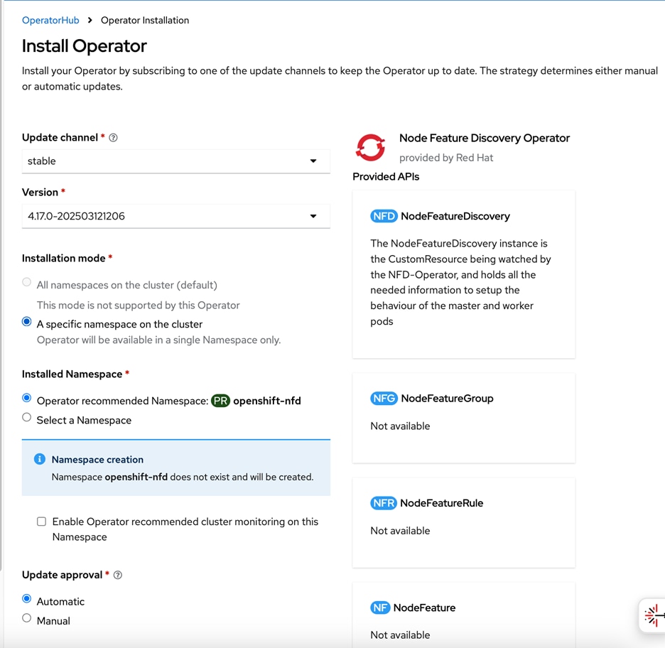
Step 6. Click Install.
Step 7. When the NFD Operator installation completes, click View Operator.
Step 8. From the top menu, choose Node Feature Discovery.
Step 9. Click Create NodeFeatureDiscovery.
Step 10. Keep the default settings and click Create.
Step 11. Confirm that the nfd-instance has a status of: Available, Upgradeable
Step 12. To confirm that NFD labelled the worker nodes with NVIDIA GPUs correctly, go to Compute > Nodes and a choose a worker node with GPU.
Step 13. Go to Details and verify that the worker node has the label:
feature.node.kubernetes.io/pci-10de.present=true
Step 14. You can also use the following CLI commands to verify (from OpenShift installer workstation) this across all nodes:
oc get nodes -l feature.node.kubernetes.io/pci-10de.present
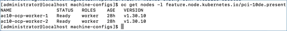
Procedure 2. Deploy the NVIDIA GPU Operator on Red Hat OpenShift
Step 1. Log into Red Hat OpenShift's cluster console.
Step 2. Go to Operators > Operator Hub and search for NVIDIA GPU Operator.
Step 3. Choose NVIDIA GPU Operator tile and click Install.
Step 4. Keep the default settings for namespace (nvidia-gpu-operator) and click Install.
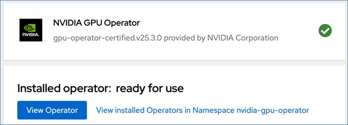
Step 5. When the installation completes, click View Operator.
Step 6. Choose the ClusterPolicy tab, then click Create ClusterPolicy. The platform assigns the default name of gpu-cluster-policy.
Step 7. Keep the default settings and click Create.
Step 8. Wait for the gpu-cluster-policy status to become Ready.
Step 9. Log into the OpenShift Installer machine and check the status of the servers with GPUs by running the following:
oc project nvidia-gpu-operator
oc get pods
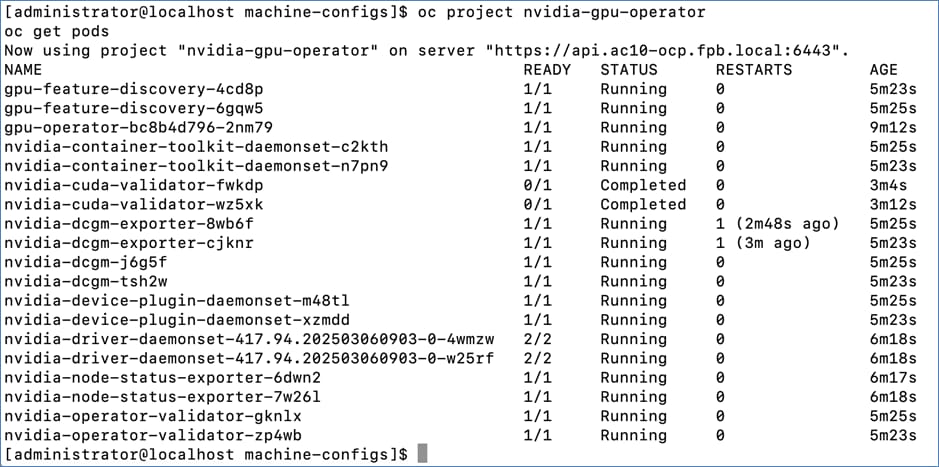
Step 10. Connect to one of the nvidia-driver-daemonset containers and view the GPU status:
oc exec -it <name of nvidia driver daemonset> –- nvidia-smi (OR)
oc exec -it <name of nvidia driver daemonset> –- bash
nvidia-smi
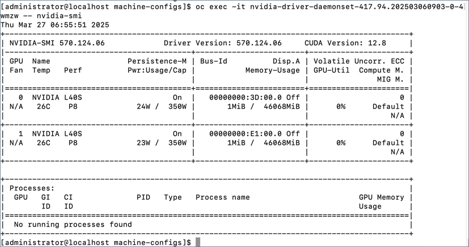
Procedure 3. Enable NVIDIA GPU (vGPU) DCGM Monitoring on Red Hat OpenShift
Step 1. Go to https://docs.nvidia.com/datacenter/cloud-native/openshift/latest/enable-gpu-monitoring-dashboard.html, enable GPU Monitoring Dashboard to monitor the GPUs from the OpenShift cluster console.
Step 2. Log into the OpenShift cluster console.
Step 3. Go to Observe > Dashboards.
Step 4. Under Dashboard, from the drop-down list and choose NVIDIA DCGM Exporter Dashboard.
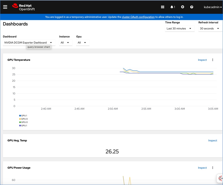
You can now use the OpenShift console to monitor the NVIDIA GPUs.
Procedure 4. Setup Taints and Tolerations
Taints and Tolerations enable nodes to control which Pods are scheduled/not scheduled on them. Node affinity is a node characteristic that makes Pods prefer a set of nodes, while taints are the exact opposite, such as it repels pods from certain nodes.
Taint allows a node to refuse a pod to be scheduled on it unless it has a matching toleration. Tolerations are applied to Pods and allow Pods to be scheduled on nodes that have a matching taint. One or more taints can be applied to a node. You apply a taint using a node specification and toleration using a pod specification.
For more information, see: https://docs.redhat.com/en/documentation/openshift_container_platform/4.17/html/nodes/controlling-pod-placement-onto-nodes-scheduling#nodes-scheduler-taints-tolerations-about_nodes-scheduler-taints-tolerations
Note: To ensure that AI/ML workloads requiring GPU resources are only deployed on nodes with GPUs assigned to them, you can configure a taint on OpenShift worker nodes with GPUs and a toleration to only allow workloads that require GPUs to be deployed on them, as detailed below.
Step 1. Log into the OpenShift Cluster console.
Step 2. Go to Compute > Nodes.
Step 3. Choose a worker node with GPU from the list.
Step 4. Click the YAML tab.
Step 5. Click Actions and choose Edit node from the drop-down list.
Step 6. Paste the following in the spec: section of the configuration:
taints:
- key: nvidia/gpu
effect: NoSchedule
Step 7. Click Save.
Step 8. Go to Workloads > Pods.
Step 9. For Project, choose nvidia-gpu-operator from the drop-down list.
Step 10. Search and find the pod name that starts with: nvidia-driver-daemonset that is running on the worker node where you deployed the taint.
Step 11. From the Details tab, click the pencil icon add the following if it doesn’t already exist:
tolerations:
- key: nvidia/gpu
operator: Exists
effect: NoSchedule
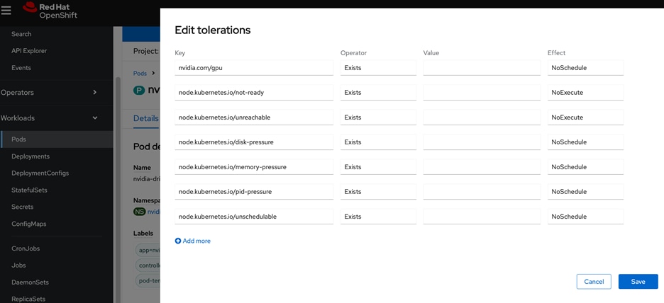
Step 12. Click Save.
Deploy Red Hat OpenShift AI for MLOps
Red Hat OpenShift AI is a complete platform for the entire lifecycle of your AI/ML projects. In this section, you will deploy Red Hat OpenShift AI as an MLOPs platform in the solution to accelerate your AI/ML projects.
Deployment Steps – Prerequisites for KServe Single-Model Serving platform
This section details the prerequisite setup required for using KServe single-model serving platform to serve large models such as Large Language Models (LLMs) in Red Hat OpenShift AI. If you’re only using OpenShift AI for multi-model serving, then you can skip this section. KServe orchestrates model serving for different types of models and includes model-serving runtimes that support a range of AI frameworks.
In this CVD, KServe is deployed in advanced deployment mode which uses Knative serverless, deployed using OpenShift Serverless Operator. Automated Install of KServe is deployed on the OpenShift cluster by configuring OpenShift AI Operator to configure KServe and its dependencies. KServe requires a cluster with a node that has at least 4 CPUs and 16GB of memory.
Note: See the Red Hat documentation for the most uptodate information on the prerequisites for a given OpenShift AI release. For the procedures outlined in this section, see this documentation
Procedure 1. Deploy Red Hat OpenShift Service Mesh Operator on a OpenShift Cluster
Note: At the time of the writing of this CVD, only OpenShift Service Mesh v2 is supported.
To support KServe for single-model serving, deploy Red Hat OpenShift Service Mesh Operator on OpenShift cluster as detailed below.
Note: Only deploy the operator – no additional configuration should be done for automatied install of KServe.
Step 1. Log into Red Hat OpenShift cluster’s web console.
Step 2. Go to Operators > Operator Hub and search for OpenShift Service Mesh.
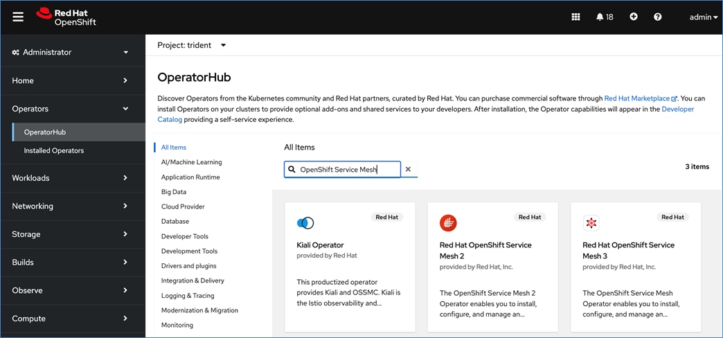
Step 3. Choose and click the Red Hat OpenShift Service Mesh 2 tile.
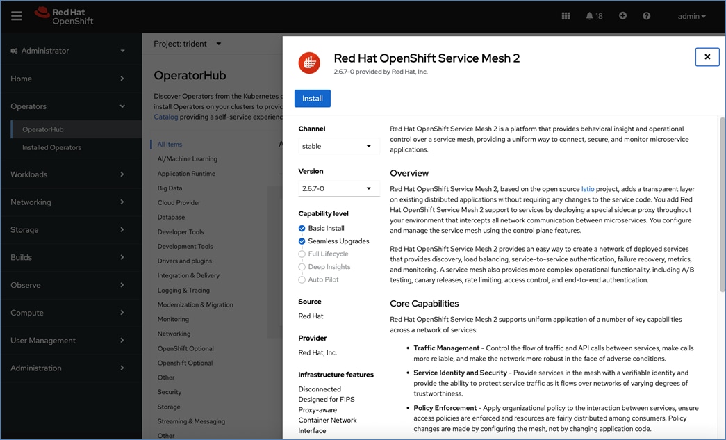
Step 4. Click Install.
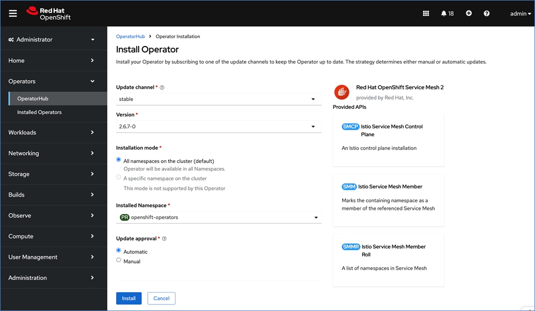
Step 5. Keep the default settings. The operator will be deployed in the openshift-operators namespace.
Step 6. Click Install.
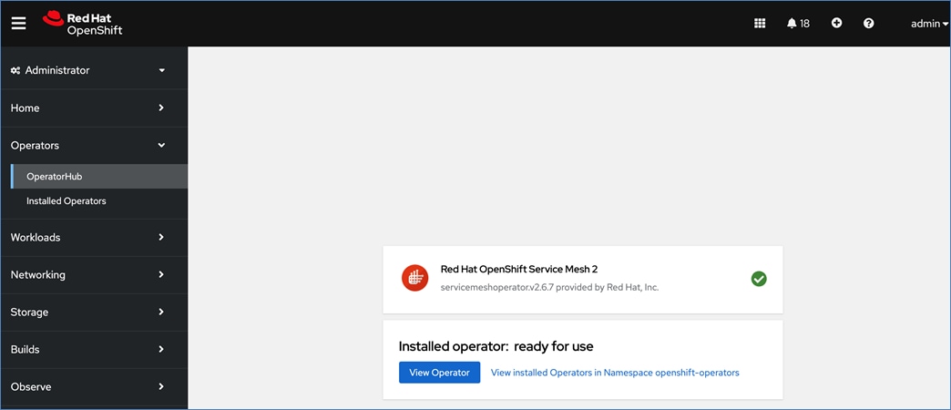
Step 7. Click View Operator and verify that the operator deployed successfully.
Procedure 2. Deploy Red Hat OpenShift Serverless on OpenShift cluster
To support KServe for single-model serving, deploy the Red Hat OpenShift Serverless Operator on the OpenShift cluster as detailed below.
Note: Only deploy the operator – no additional configuration should be done for automatied install of KServe.
Step 1. Log into Red Hat OpenShift cluster’s web console.
Step 2. Go to Operators > Operator Hub and search for OpenShift Serverless.
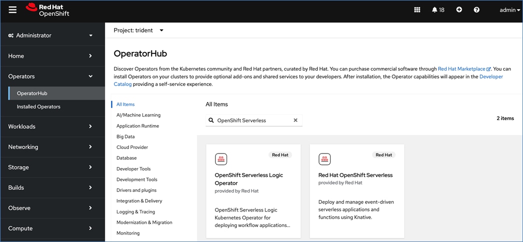
Step 3. Choose and click the Red Hat OpenShift Serverless tile.
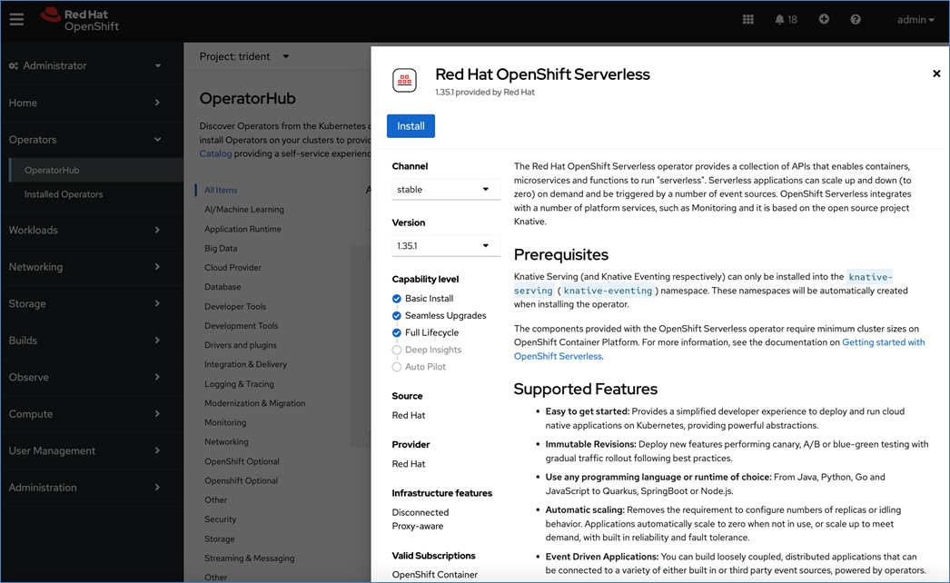
Step 4. Click Install.
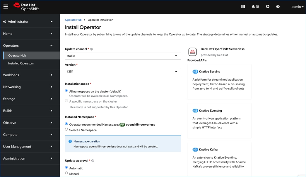
Step 5. Keep the default settings. The operator will be deployed in a new openshift-serverless namespace.
Step 6. Click Install.
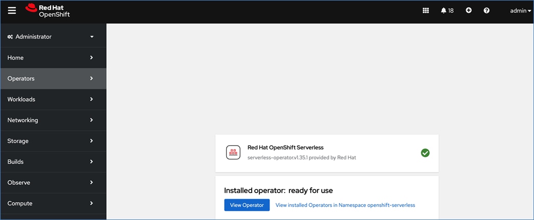
Step 7. Click View Operator and verify that the operator deployed successfully.
Procedure 3. Deploy Red Hat Authorino on OpenShift Cluster
To support KServe for single-model serving, deploy the Red Hat Authoring Operator on the OpenShift cluster to add an authorization provider as detailed below.
Note: Only deploy the operator – no additional configuration should be done for automatied install of KServe.
Step 1. Log into the Red Hat OpenShift cluster’s web console.
Step 2. Go to Operators > Operator Hub and search for Authorino.
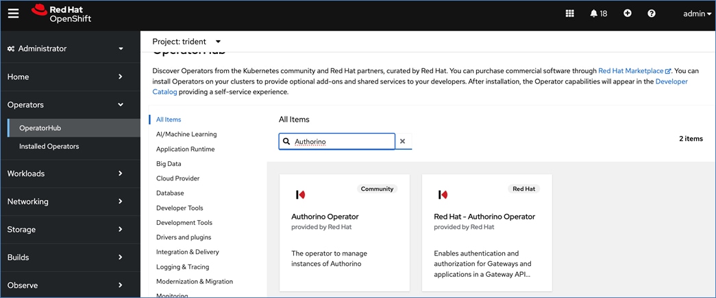
Step 3. Choose and click the Red Hat – Authorino Operator tile.
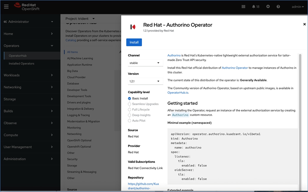
Step 4. Click Install.
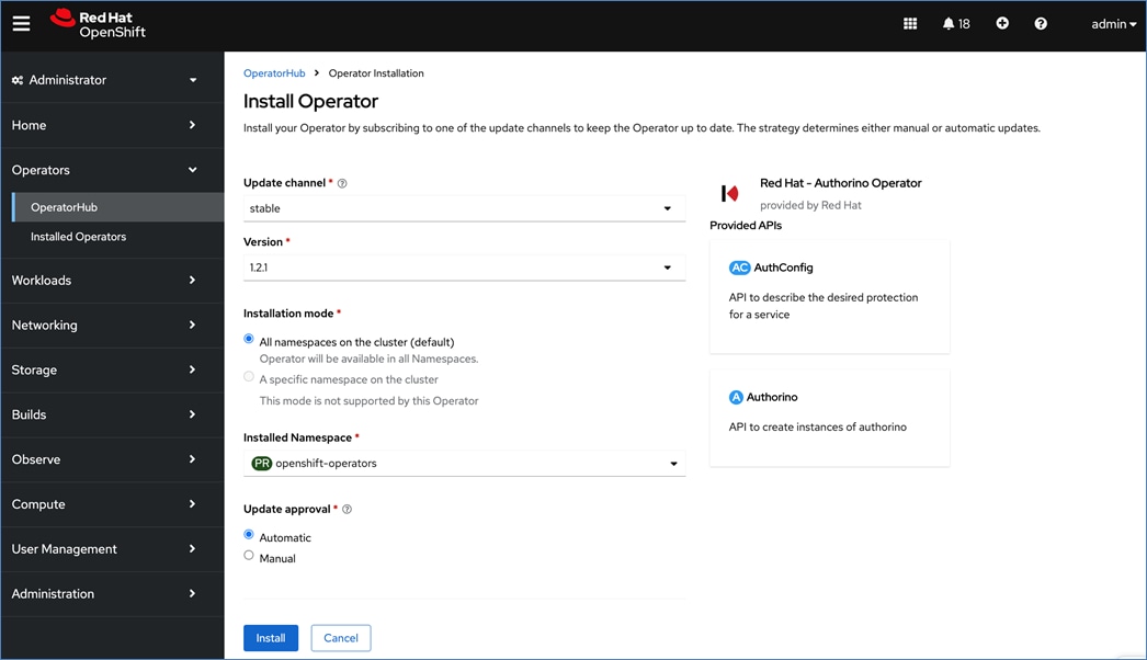
Step 5. Keep the default settings. The operator will be deployed in the openshift-operators namespace.
Step 6. Click Install.
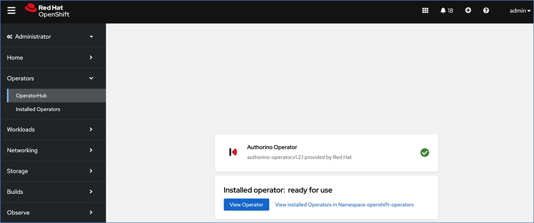
Step 7. Click View Operator and verify that the operator deployed successfully.
Deployment Steps – Deploy Red Hat OpenShift AI Operator
This section details the procedures for deploying Red Hat Openshift AI on a Red Hat OpenShift cluster to enable an MLOps platform to develop and operationalize AI/ML use cases.
Prerequisites
● OpenShift cluster deployed with 2 worker nodes, each with at least 8 CPUs and 32 GiB RAM available for OpenShift AI to use. Additional cluster resources maybe required depending on the needs of the individual AI/ML projects supported by OpenShift AI.
● OpenShift cluster is configured to use a default storage class that can be dynamically provisioned to provide persistent storage. This is provided by NetApp Trident in this solution.
● Access to S3-compatible object store with write access. In this solution, NetApp storage provides this. The object store is used by OpenShift AI for use as:
◦ Model Repo to store models that will used for model serving in inferencing use cases
◦ Pipeline Artifacts to store data science pipeline runs logs, results and other artifacts or metadata.
◦ Data storage to store large data sets that maybe used by data scientists to test or experiment with.
◦ Input or Output data for Distributed Workloads
● Identity provider configured for OpenShift AI (same as Red Hat OpenShift Container Platform). You cannot use OpenShift administrator (kubeadmin) for OpenShift AI. You will need to define a separate user with cluster-admin role to access OpenShift AI.
● Internet Access, specifically access to the following locations. cdn.redhat.com
◦ subscription.rhn.redhat.com
◦ registry.access.redhat.com
◦ registry.redhat.io
◦ quay.io
● If using NVIDIA GPUs and other NIVIDA resources, then above access should include:
◦ ngc.download.nvidia.cn
◦ developer.download.nvidia.com
● Verify that the following perquisites from the previous section have been successfully deployed. The following are required to support the different uses cases that were validated as a part of this solution. See Solution Validation section of this document for more details on these use cases.
◦ Red Hat OpenShift Serverless Operator to support single-model serving of large models using Kserve.
◦ Red Hat OpenShift Service Mesh to support single-model serving.
◦ Red Hat Authorino Operator to add an authorization provider to support single-model serving.
Procedure 1. Deploy Red Hat OpenShift AI Operator on the OpenShift Cluster
Step 1. Log into the Red Hat OpenShift cluster console.
Step 2. Go to Operators > Operator Hub and search for OpenShift AI.
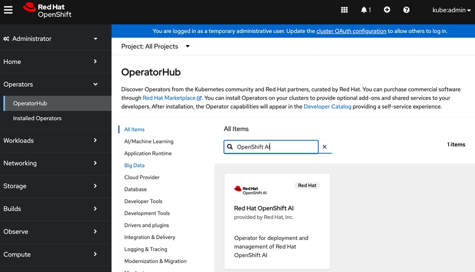
Step 3. Click the Red Hat OpenShift AI tile.
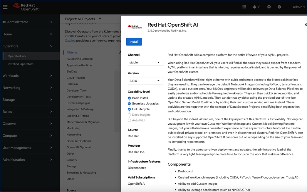
Step 4. Click Install.
Step 5. Keep the default settings. The operator will be deployed in the redhat-ods-operator namespace.
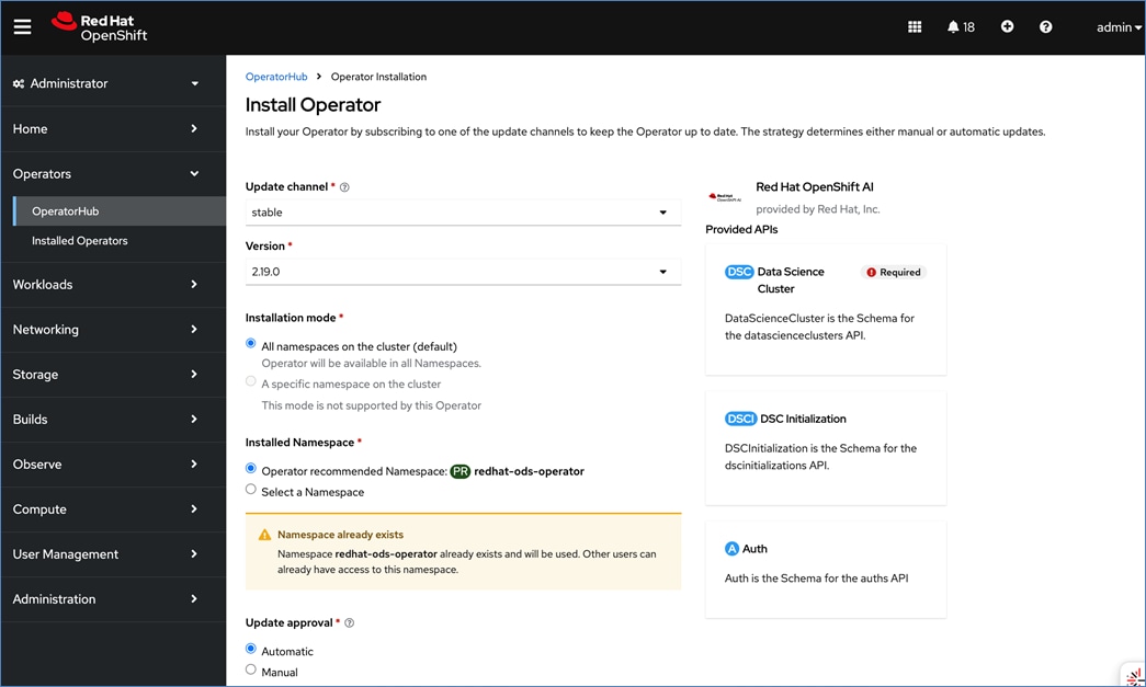
Step 6. Click Install.
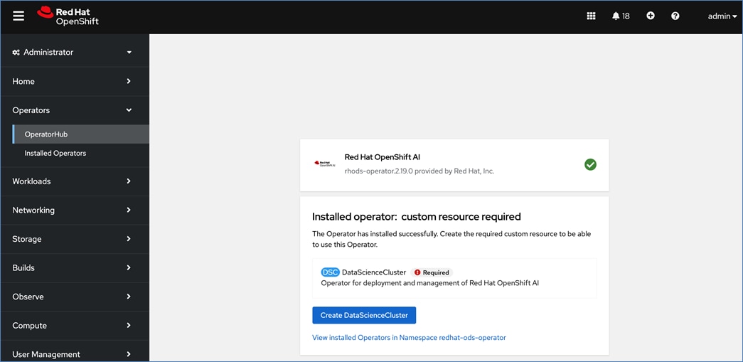
Step 7. When the installation completes, click Create DataScienceCluster.
Step 8. For Configure via, choose YAML view.
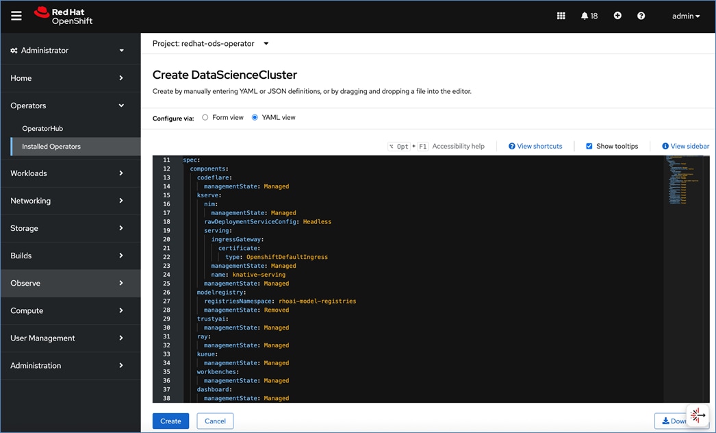
Step 9. Review the OpenShift AI components under spec > components. Verify that kserve component’s managementState is Managed.
Step 10. Click Create.
Step 11. When the installation completes, view the operator status by clicking the All instances tab. It should have a status of Ready.
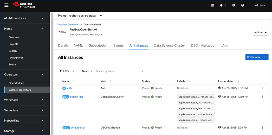
Procedure 2. Set up the OpenShift AI admin user
Before you can use OpenShift AI, you will need to setup an OpenShift AI admin user in order to log in and setup the environment as an OpenShift AI administrator.
Note: OpenShift administrator (kubeadmin) does not have Administrator privileges in OpenShift AI and as such Settings will not be an available menu option.
Step 1. Log into the OpenShift Installer machine and go to the cluster directory.
Step 2. Run the following command to create an user with administrator privileges:
Note: You can specify any username. In this CVD, we used admin as shown below:
htpasswd -c -B -b ./admin.htpasswd admin <specify_password>
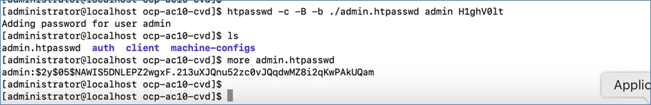
Step 3. Copy the contents of the admin.htpasswd and log into the OpenShift cluster console.
Step 4. You will see a message as shown below, indicating that you’re logged in as a temporary administrative user. Click the link to update the cluster OAuth configuration.
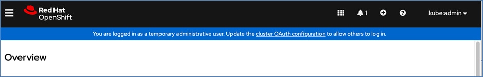
Step 5. In the Cluster OAuth configuration window, for IDP, choose HTPasswd from the drop-down list.
Step 6. In the Add Identify Provider:HTPasswd window, paste the contents of the admin.htpasswd file as shown below:
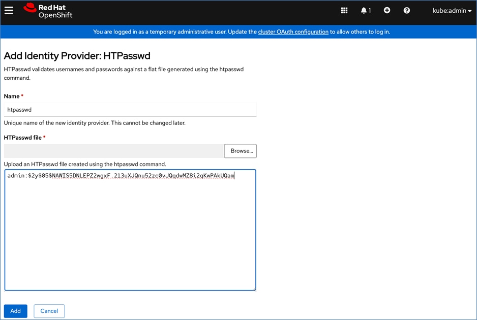
Step 7. Click Add.
Step 8. Go to User Management > Users.
Step 9. Choose the user that was previously created using htpasswd. Click the username.
Step 10. In the User > User Details window, go to the RoleBindings tab.
Step 11. Click Create binding.
Step 12. In the Create Rolebinding window, click Cluster-wide role binding (ClusterRoleBinding).
Step 13. Specify a name, such as oai-admin.
Step 14. For Role Name, choose cluster-admin from the drop-down list.
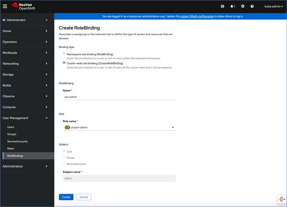
Step 15. Click Create.
Step 16. Log into the OpenShift AI. If you were previously logged in, you may want to open a browser window in Incognito mode to log in using the new account.
Step 17. To log into OpenShift AI, click the square tile and choose Red Hat OpenShift AI from the drop-down list.
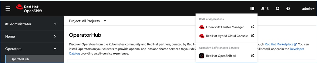
Step 18. Click htpasswd.
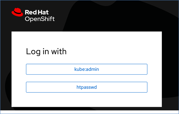
Step 19. Log in using the new account and now you’ll see the Settings since you’re an administrator. You can now start setting up and use the environment for your AI/ML projects.
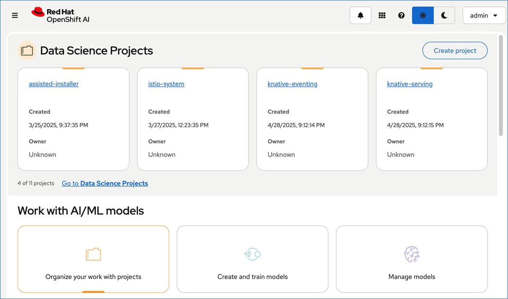
Visibility and Monitoring – GPU
The GPUs deployed on Cisco UCS systems in the solution can be observed and monitored using the tools detailed in this section.
Visibility
Cisco Intersight allows you to manage Cisco UCS servers, including the GPU or PCIe (X440p) nodes with GPUs. Each GPU node is paired with an adjacent compute server as shown below:
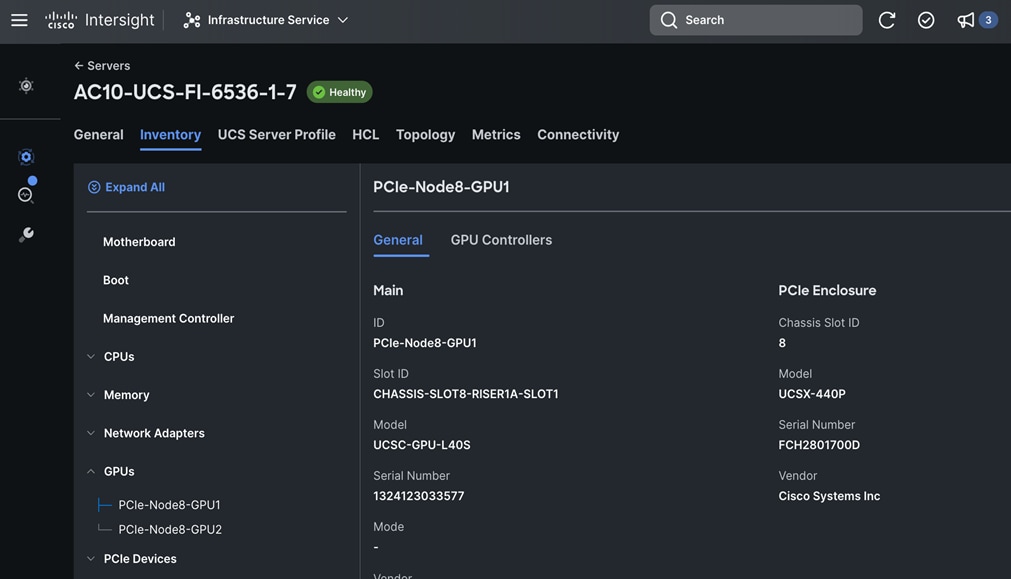
In addition to centralized provisioning and orchestration that Cisco Intersight provides, it also provides visibility across all sites and locations that an enterprise has. Enterprises can use either built-in or custom dashboards. For example, power and energy consumption is a critical consideration in AI/ML deployments and a dashboard such as the one shown below can help Enterprises understand their consumption pattern more efficiently.
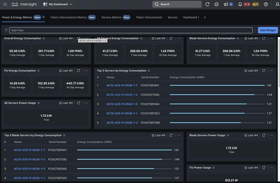
Power and energy statistics on a per server is also possible and important to track for GPU workloads.
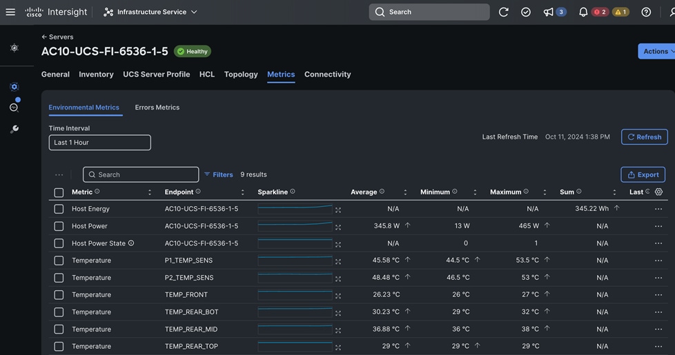
Monitoring
To monitor the GPU utilization, memory, power and metrics, the solution uses the following tools to get a consolidated view. Alternatively, a Grafana dashboard can be set up to enable a consolidated view – this is outside the scope of this solution.
● Red Hat OpenShift observability dashboard available from the OpenShift cluster console
● nvidia-smi CLI tool that NIVIDA provides for Red Hat OpenShift
GPU Monitoring from Red Hat OpenShift Dashboard
The OpenShift dashboard uses Prometheus metrics. NVIDIA GPU Operator exposes DCGM metrics to Prometheus that the dashboard uses to display GPU metrics available to OpenShift. NVIDIA GPU Operator, when deployed will expose DCGM metrics to the OpenShift that can be viewed from the integrated dashboard.
To view the metrics exposed by DCGM exporter in OpenShift, see the following file available here. When creating custom dashboards using Grafana, the exact metric and query to use can be found here. Also, a JSON file with the metrics is available for Grafana from the same repo. Grafana community operator is available on Red Hat Operator Hub and can be deployed as needed for a customized view.
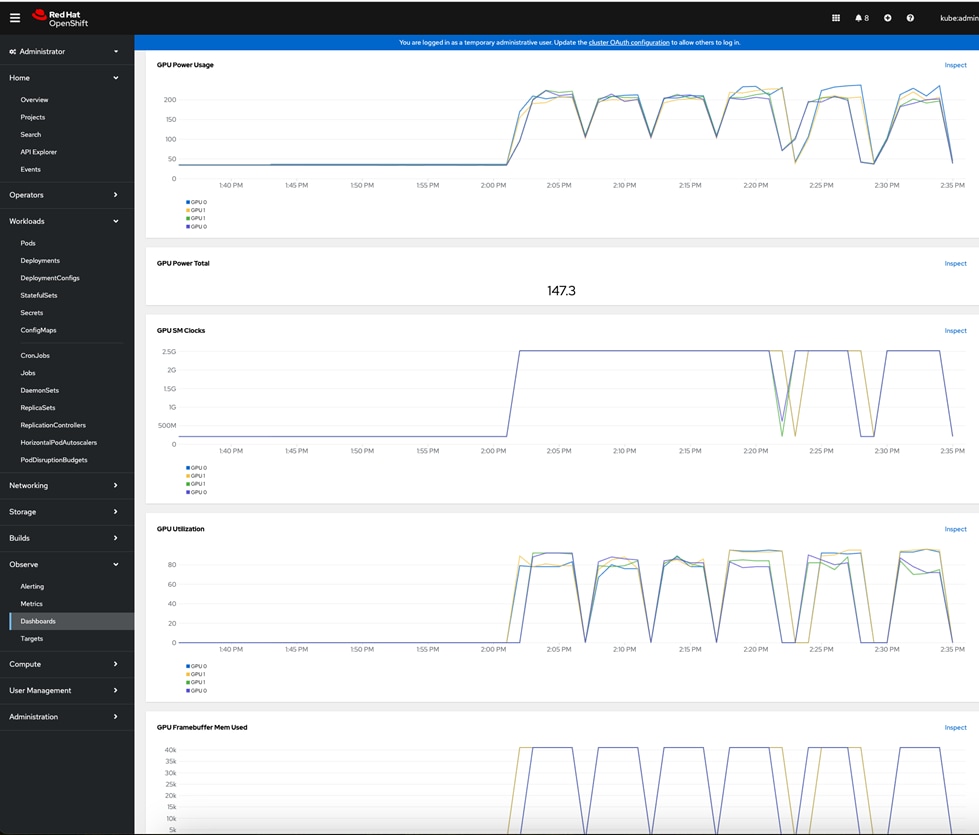
The OpenShift dashboard currently displays the following default metrics for a GPU (Table 15).
| GPU Metric |
Description |
| GPU Temperature |
GPU temperature on a per GPU basis in Centigrade |
| GPU Avg. Temperature |
GPU temperature average across all GPUs |
| GPU Power Usage |
On a per-GPU basis. |
| GPU Power Total |
Total across all GPUs |
| GPU SM Clocks |
SM clock frequency in hertz. |
| GPU Utilization |
GPU utilization percentage |
| GPU Framebuffer Mem Used |
Frame buffer memory used in MB. |
| Tensor Core Utilization |
Ratio of cycles the tensor (HMMA) pipe is active, percent. |
NVIDIA CLI tool for Red Hat Openshift
NVIDIA provides the nvidia-smi CLI tool to collect GPU metrics and other details from the GPU in OpenShift and as outlined below:
In Red Hat OpenShift, execute the following commands from OpenShift installer workstation:
oc exec -it nvidia-driver-daemonset-<version> -- nvidia-smi (-q)
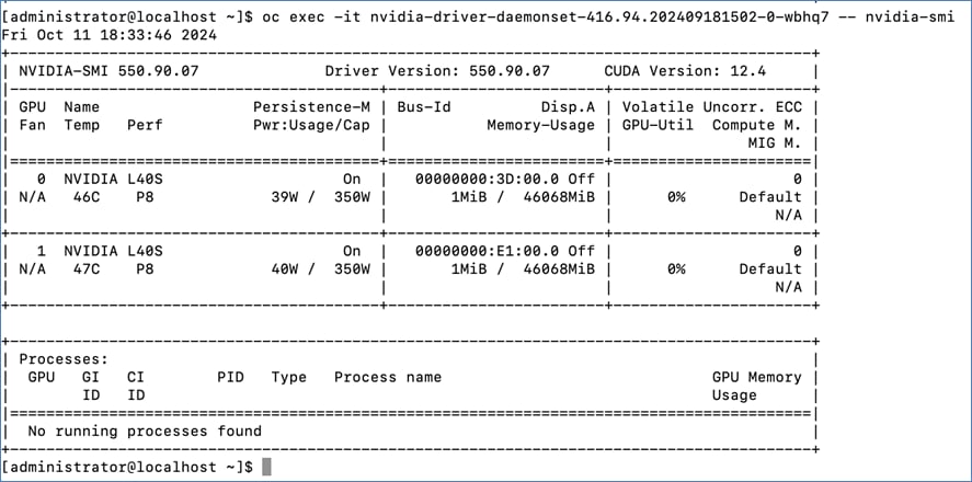
Solution Validation
This chapter contains the following:
● Hardware and Software Matrix
Table 16 lists the hardware and software components that were used to validate the solution in Cisco labs.
Table 16. Hardware/Software Matrix
| Component (PID) |
Software/Firmware |
Notes |
| MLOps |
||
| Red Hat OpenShift AI Operator |
2.19s* |
Involves multiple pre-integrated & custom software components |
| Kubernetes (K8s) – Red Hat OpenShift |
||
| Red Hat OpenShift |
4.17.20 |
Deployed using Assisted Installer from console.redhat.com |
| Red Hat Node Feature Discovery Operator |
4.17.0-202503121206 |
Identifies and labels GPU |
| Kubernetes (K8s) Storage |
||
| NetApp Trident Operator |
25.2.0 |
|
| GPU |
||
| NVIDIA GPU Operator |
24.6.2 |
|
| NVIDIA L40S GPU Driver |
550.90.07 |
|
| CUDA Version |
12.4 |
Minimum Version |
| Compute |
||
| Cisco UCS X-Series |
||
| Cisco UCS 6536 Fabric Interconnects |
4.3(4.240066) |
Intersight recommended version |
| Cisco UCS X9508 Chassis |
N/A |
|
| Cisco UCS X9108-100G IFM |
N/A |
|
| Cisco UCS X210c M7 Compute Nodes |
5.2(2.240074) |
|
| PCIe Mezzanine Card for UCS X-Server |
N/A |
|
| Cisco UCS X440p PCIe Node |
N/A |
|
| NVIDIA GPU |
FW: 95.02.66.00.02-G133.0242.00.03 |
L40S: 350W, 48GB, 2-Slot FHFL |
| Cisco VIC 15231 MLOM |
5.3(3.91) |
2x100G mLOM |
| Storage |
||
| NetApp AFF C800 |
ONTAP 9.16.1 |
NFS, iSCSI, NVME-TCP, and S3 |
| Network |
||
| Cisco Nexus 93600CD-GX |
NXOS 10.4(3) |
Top-of-rack 100/400GbE switches |
| Other |
||
| Cisco Intersight |
N/A |
|
* Red Hat OpenShift AI versions were upgraded as we progressed through the testing. The version shown in the table is the version running at the time of the writing of this guide.
The interoperability information for the different components in the solution are summarized in Table 17.
| Component |
Interoperability Matrix and Other Relevant Links |
| Cisco UCS Hardware Compatibility Matrix (HCL) |
|
| NVIDIA Licensing |
|
| NVIDIA Certification |
https://www.nvidia.com/en-us/data-center/products/certified-systems/ |
| NVIDIA AI Enterprise Qualification and Certification |
|
| NVIDIA Driver Lifecycle, Release and CUDA Support |
https://docs.nvidia.com/datacenter/tesla/drivers/index.html#lifecycle |
| NetApp IMT |
The following GPU focused validation was completed:
● GPU Functional Validation – Sample CUDA Application.
● GPU Stress/Load Test using GPU Burn Tests from: https://github.com/wilicc/gpu-burn. The test iterates up to max. GPU utilization to ensure that the GPU is performing (Tflop/s) as it should before we add AI/ML workloads to Red Hat OpenShift.
● Same PyTorch script executed from Jupyter Notebooks on Red Hat OpenShift – see the Sample GPU Tests folder in https://github.com/ucs-compute-solutions/FlexPod-OpenShift-AI
The following sections show the results of the above-mentioned sanity tests.
Sample CUDA Application Test
Configuration YAML file:
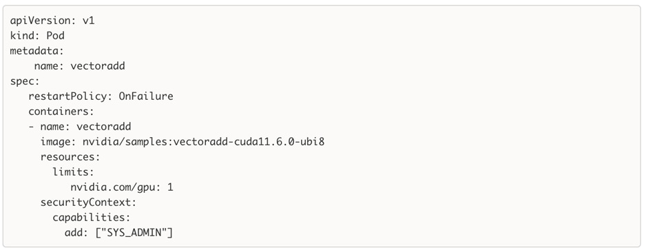
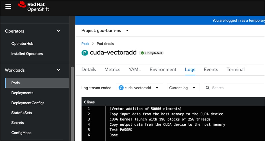
Sample GPU Burn Test
The specifics of this test can be found in the GitHub repo provided earlier. Results of executing the test are provided in this section.
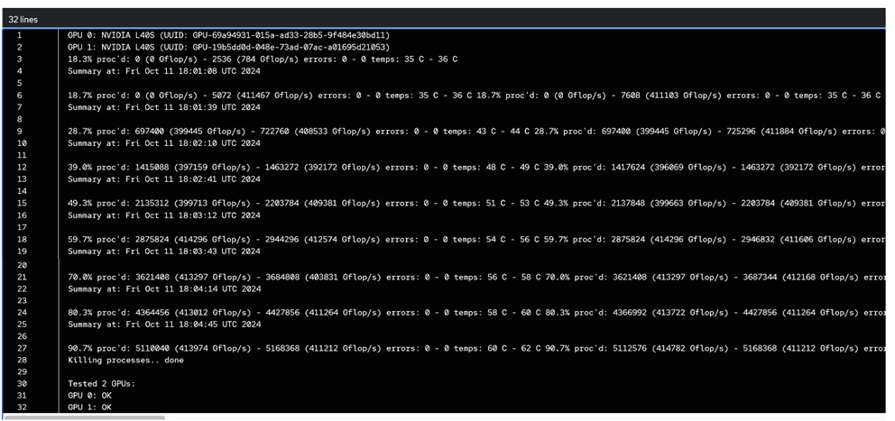
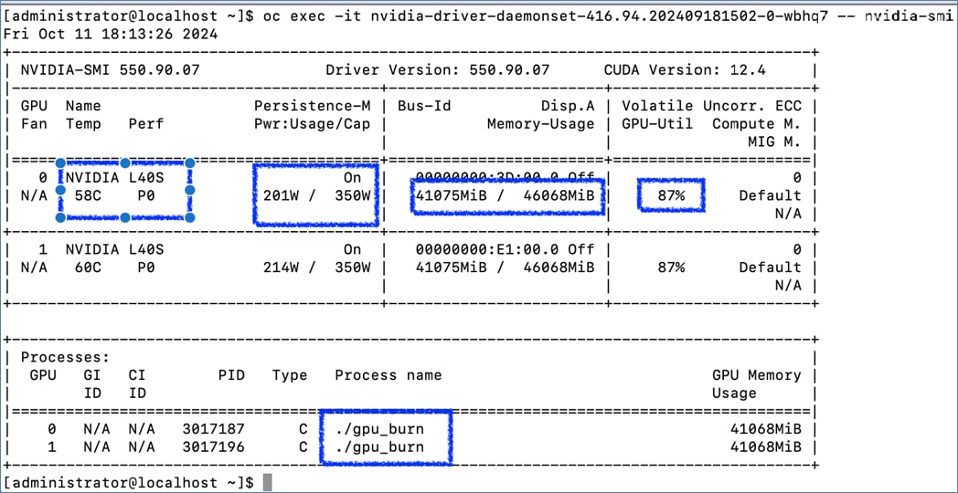
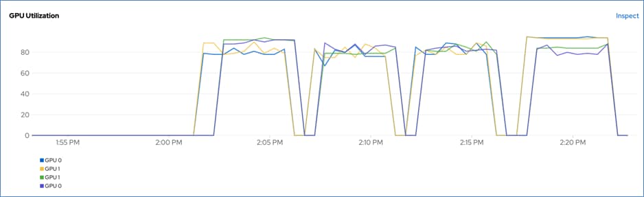
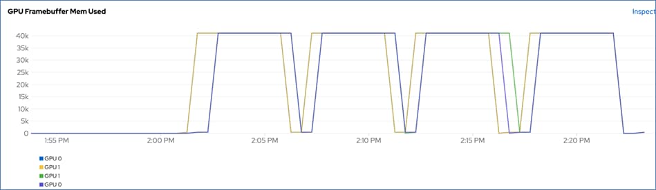
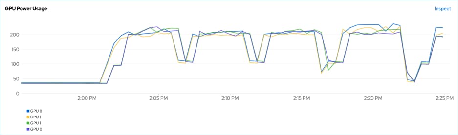

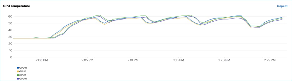

A summary of the AI/ML use cases and other testing that were validated for this effort are listed below. The code for these use cases will be made available on GitHub repo (link below) in the near future.
● Fraud Detection - Basic validation of a simple model using TensorFlow across the MLOps lifecycle. This model is an example in which transactions are analyzed using previous labeled data as either fraudulent or valid. This model would generally be called as part of real time transaction processing in financial institutions.
● Object Detection - Validation of a more advanced predictive AI Model. In this case we used PyTorch and YOLOv8 object detection. Starting from an open-source model, we retrain that model on new labeled data giving the ability for the model to detect car accidents. While not necessary, we see the benefits of using GPUs to reduce training time. As a service API, this model could be consumed by applications using traffic cameras to detect accidents or other uses.
● Text to Image - Used to determine viability of Generative AI on the platform. Throughout the MLOps lifecycle, GPU accelerators are required. We started stable diffusion for image generation using PyTorch and CUDA 11.8. The demo involves fine-tuning the model using a small amount of custom data, exporting, and saving model in ONNX format to a model repo, andoperationalizing the model into production using an inferencing server for use by application teams.
● NVIDIA Inference Microservices (NIM) – Validation of NVIDIA NIM on OpenShift AI represents a powerful integration aimed at optimizing AI inferencing and accelerating the deployment of generative AI applications. The integration supports performance-optimized foundation and embedding models, enabling faster time to value for AI applications.
● RAG Chatbot – Validation of an Enterprise chatbot using RAG. Milvus Vector store will be first deployed. A sample collection of Enterprise data will then be ingested into a Milvus Vector store with LangChain and Hugging Face embedding model. A vLLM Inferencing server will be deployed with Mistral-7b-Instruct or an equivalent LLM. We will then use input from the chatbot (built using Gradio) to generate a query to vector store and query output, along with original Chatbot input will be used to generate an inferencing request to the LLM running on the inferencing server and the response deployed on the chatbot GUI
● Fine-Tune pre-trained Llama3.1 models – Validation of fine-tuning LLMs using Ray on OpenShift AI. Ray is a distributed computing framework, and the Kubernetes operator for Ray makes it easy to provision resilient and secure Ray clusters that can leverage the compute resources available on any infrastructure. The model will be fine-tuned using HF transformers, Accelerate, PEFT (LoRA), DeepSpeed and a training example from Ray.
The use case code for the validated use cases and automation used in this solution will be made available on GitHub in the future: https://github.com/ucs-compute-solutions/FlexPod-OpenShift-AI
Conclusion
Taking AI/ML projects from proof-of-concept to production is a significant challenge for organizations due to the complexity involved. Even with a production-ready ML model, integrating it into an enterprise application and data pipelines are challenging. For an Enterprise, scaling these efforts across multiple applications requires an operational framework that is sustainable.
A critical strategic decision that enterprises can make from the get-go is to have a plan for operationalizing their AI/ML efforts with consistency and efficiency. Instead of ad-hoc efforts that add to the technical debt, adopting processes, tools, and best-practices is essential for delivering models quickly and efficiently. Implementing MLOps is a crucial step toward this goal. MLOps integrates successful DevOps practices into machine learning, promoting collaboration, automation, and CI/CD to speed up model delivery.
The FlexPod AI solution using Red Hat OpenShift AI offers a comprehensive, flexible, and scalable platform for supporting an Enterprise’s AI/ML efforts. Red Hat OpenShift AI provides both pre-integrated and custom tools and technologies to accelerate AI/ML efforts and operationalize AI in a repeatable manner, with consistency and efficiency.
The FlexPod infrastructure is a proven platform in enterprise data centers, delivering a high-performance and flexible architecture for demanding applications such as SAP, Oracle, HPC and graphics-accelerated VDI. Cisco Intersight, a SaaS platform, simplifies IT operations with comprehensive management and visibility across the FlexPod datacenter, including GPUs and sustainability dashboards. FlexPod AI extends existing FlexPod datacenter capabilities to streamline AI infrastructure deployments and accelerate AI/ML efforts by reducing complexity.
This CVD provides a comprehensive solution for hosting AI/ML workloads in enterprise data centers, enabling enterprises to accelerate and operationalize AI/ML efforts quickly and at scale.
About the Authors
Archana Sharma, Technical Marketing, Cisco UCS Compute Solutions, Cisco Systems Inc.
Archana Sharma is a Technical Marketing Engineer with over 20 years of experience at Cisco on a variety of technologies that span Data Center, Desktop Virtualization, Collaboration, and other Layer2 and Layer3 technologies. Archana currently focusses on the design and deployment of Cisco UCS based solutions for Enterprise data centers, specifically Cisco Validated designs and evangelizing the solutions through demos and industry events such as Cisco Live. Archana holds a CCIE (#3080) in routing and switching and a bachelor’s degree in electrical engineering from North Carolina State University.
Abhinav Singh, Sr. Technical Marketing Engineer, Hybrid Cloud Infra & OEM Solutions, NetApp
Abhinav Singh is a Senior Technical Marketing Engineer for the Converged Infrastructure Solutions team at NetApp, who has over 15 years of expertise in Data Center Virtualization, Networking, and Storage. Abhinav specializes in designing, validating, implementing, and supporting Converged Infrastructure solutions, encompassing Data Center Virtualization, Hybrid Cloud, Cloud Native, Database, Storage, and Gen AI. Abhinav holds a bachelor's degree in electrical and electronics engineering.
Acknowledgements
For their support and contribution to the design, validation, and creation of this Cisco Validated Design, the authors would like to thank:
● John George, Technical Marketing Engineer, Cisco Systems, Inc.
● Karl Eklund, Principal Consultant – AI, Red Hat
● Roberto Carratalá, Principal AI Platform Architect, Red Hat
Appendix
This appendix contains the following:
● Appendix A – References used in this guide
Appendix A – References used in this guide
FlexPod
Cisco Design Zone for FlexPod CVDs: https://www.cisco.com/c/en/us/solutions/design-zone/data-center-design-guides/data-center-design-guides-all.html#FlexPod
Cisco Unified Computing System (UCS)
Cisco UCS Hardware Compatibility Matrix: https://ucshcltool.cloudapps.cisco.com/public/
Cisco Intersight: https://www.intersight.com
Cisco Intersight Managed Mode: https://www.cisco.com/c/en/us/td/docs/unified_computing/Intersight/b_Intersight_Managed_Mode_Configuration_Guide.html
Cisco Unified Computing System: http://www.cisco.com/en/US/products/ps10265/index.html
Cisco UCS 6536 Fabric Interconnects: https://www.cisco.com/c/en/us/products/collateral/servers-unified-computing/ucs6536-fabric-interconnect-ds.html
Cisco Network
Cisco Nexus 9000 Series Switches: http://www.cisco.com/c/en/us/products/switches/nexus-9000-series-switches/index.html
NVIDIA GPUs
Certification: https://www.nvidia.com/en-us/data-center/products/certified-systems/
NetApp Storage
NetApp IMT: https://mysupport.netapp.com/matrix/#welcome
NetApp AFF C-Series: https://www.netapp.com/data-storage/aff-c-series/
NetApp AFF A-Series: https://www.netapp.com/data-storage/aff-a-series
NetApp ASA: https://www.netapp.com/data-storage/all-flash-san-storage-array/
NetApp FAS: https://www.netapp.com/data-storage/fas/
NetApp ONTAP: https://docs.netapp.com/ontap-9/index.jsp
NetApp Trident: https://docs.netapp.com/us-en/trident/
NetApp Active IQ UM: https://docs.netapp.com/us-en/active-iq-unified-manager/
Red Hat OpenShift
Red Hat OpenShift Operators: https://www.redhat.com/en/technologies/cloud-computing/openshift/what-are-openshift-operators
Red Hat OpenShift Ecosystem catalog: https://catalog.redhat.com/software/search?deployed_as=Operator
Automation
GitHub repository for Cisco UCS solutions: https://github.com/ucs-compute-solutions/
Feedback
For comments and suggestions about this guide and related guides, join the discussion on Cisco Community here: https://cs.co/en-cvds.
CVD Program
ALL DESIGNS, SPECIFICATIONS, STATEMENTS, INFORMATION, AND RECOMMENDATIONS (COLLECTIVELY, "DESIGNS") IN THIS MANUAL ARE PRESENTED "AS IS," WITH ALL FAULTS. CISCO AND ITS SUPPLIERS DISCLAIM ALL WARRANTIES, INCLUDING, WITHOUT LIMITATION, THE WARRANTY OF MERCHANTABILITY, FITNESS FOR A PARTICULAR PURPOSE AND NONINFRINGEMENT OR ARISING FROM A COURSE OF DEALING, USAGE, OR TRADE PRACTICE. IN NO EVENT SHALL CISCO OR ITS SUPPLIERS BE LIABLE FOR ANY INDIRECT, SPECIAL, CONSEQUENTIAL, OR INCIDENTAL DAMAGES, INCLUDING, WITHOUT LIMITATION, LOST PROFITS OR LOSS OR DAMAGE TO DATA ARISING OUT OF THE USE OR INABILITY TO USE THE DESIGNS, EVEN IF CISCO OR ITS SUPPLIERS HAVE BEEN ADVISED OF THE POSSIBILITY OF SUCH DAMAGES.
THE DESIGNS ARE SUBJECT TO CHANGE WITHOUT NOTICE. USERS ARE SOLELY RESPONSIBLE FOR THEIR APPLICATION OF THE DESIGNS. THE DESIGNS DO NOT CONSTITUTE THE TECHNICAL OR OTHER PROFESSIONAL ADVICE OF CISCO, ITS SUPPLIERS OR PARTNERS. USERS SHOULD CONSULT THEIR OWN TECHNICAL ADVISORS BEFORE IMPLEMENTING THE DESIGNS. RESULTS MAY VARY DEPENDING ON FACTORS NOT TESTED BY CISCO.
CCDE, CCENT, Cisco Eos, Cisco Lumin, Cisco Nexus, Cisco StadiumVision, Cisco TelePresence, Cisco WebEx, the Cisco logo, DCE, and Welcome to the Human Network are trademarks; Changing the Way We Work, Live, Play, and Learn and Cisco Store are service marks; and Access Registrar, Aironet, AsyncOS, Bringing the Meeting To You, Catalyst, CCDA, CCDP, CCIE, CCIP, CCNA, CCNP, CCSP, CCVP, Cisco, the Cisco Certified Internetwork Expert logo, Cisco IOS, Cisco Press, Cisco Systems, Cisco Systems Capital, the Cisco Systems logo, Cisco Unified Computing System (Cisco UCS), Cisco UCS B-Series Blade Servers, Cisco UCS C-Series Rack Servers, Cisco UCS S-Series Storage Servers, Cisco UCS X-Series, Cisco UCS Manager, Cisco UCS Management Software, Cisco Unified Fabric, Cisco Application Centric Infrastructure, Cisco Nexus 9000 Series, Cisco Nexus 7000 Series. Cisco Prime Data Center Network Manager, Cisco NX-OS Software, Cisco MDS Series, Cisco Unity, Collaboration Without Limitation, EtherFast, EtherSwitch, Event Center, Fast Step, Follow Me Browsing, FormShare, GigaDrive, HomeLink, Internet Quotient, IOS, iPhone, iQuick Study, LightStream, Linksys, MediaTone, MeetingPlace, MeetingPlace Chime Sound, MGX, Networkers, Networking Academy, Network Registrar, PCNow, PIX, PowerPanels, ProConnect, ScriptShare, SenderBase, SMARTnet, Spectrum Expert, StackWise, The Fastest Way to Increase Your Internet Quotient, TransPath, WebEx, and the WebEx logo are registered trade-marks of Cisco Systems, Inc. and/or its affiliates in the United States and certain other countries. (LDW_P1)
All other trademarks mentioned in this document or website are the property of their respective owners. The use of the word partner does not imply a partnership relationship between Cisco and any other company. (0809R)