FlashStack for SAP HANA TDI with Cisco UCS M6 X-Series
Available Languages
Bias-Free Language
The documentation set for this product strives to use bias-free language. For the purposes of this documentation set, bias-free is defined as language that does not imply discrimination based on age, disability, gender, racial identity, ethnic identity, sexual orientation, socioeconomic status, and intersectionality. Exceptions may be present in the documentation due to language that is hardcoded in the user interfaces of the product software, language used based on RFP documentation, or language that is used by a referenced third-party product. Learn more about how Cisco is using Inclusive Language.
- US/Canada 800-553-2447
- Worldwide Support Phone Numbers
- All Tools
 Feedback
 Feedback

In partnership with:

About the Cisco Validated Design Program
The Cisco Validated Design (CVD) program consists of systems and solutions designed, tested, and documented to facilitate faster, more reliable, and more predictable customer deployments. For more information, go to: http://www.cisco.com/go/designzone.
FlashStack® for SAP HANA TDI is a validated, converged infrastructure solution developed jointly by Cisco and Pure Storage. The solution offers a predesigned data center architecture that incorporates the Cisco Unified Computing System (Cisco UCS) X-Series modular platform, Cisco UCS B-Series, and Cisco UCS C-Series, the all-flash enterprise storage FlashArray//X, and networking to reduce IT risk by validating the architecture and helping ensure compatibility among the components. FlashStack is a great choice for SAP ERP, SAP HANA, virtualization, and other enterprise applications.
This document explains the design details of incorporating the Cisco UCS X-Series modular platform into the FlashStack for SAP HANA TDI solution and its ability to manage and orchestrate FlashStack components from the cloud using Cisco Intersight. Some of the most important advantages of integrating Cisco UCS X-Series into the FlashStack infrastructure include:
● Simpler and programmable infrastructure: Infrastructure as code delivered through an open application programming interface (API).
● Power and cooling innovations: Higher-power headroom and lower energy loss because of a 54V DC power delivery to the chassis.
● Better airflow: Midplane free design with fewer barriers, thus lower impedance.
● Fabric innovations: PCIe/Compute Express Link (CXL) topology for heterogeneous compute and memory composability.
● Innovative cloud operations: Continuous feature delivery and infrastructure management.
● Built for investment protections: Design-ready for future technologies such as liquid-cooling and high-wattage CPUs; CXL ready.
In addition to the compute-specific hardware and software innovations, integration of the Cisco Intersight cloud platform with VMware vCenter Server and FlashArray’s Purity operating environment delivers monitoring, orchestration, and workload optimization capabilities for different layers (virtualization and storage) of the FlashStack solution.
If you are interested in understanding the FlashStack design and deployment details, including configuration of various elements of design and associated best practices, please refer to Cisco Validated Designs for FlashStack here: https://www.cisco.com/c/en/us/solutions/design-zone/data-center-design-guides/data-center-design-guides-all.html#FlashStack.
This chapter contains the following:
● Audience
The Cisco UCS X-Series is a new modular compute system configured and managed from the cloud. It is designed to meet the needs of modern applications and improve operational efficiency, agility, and scale through an adaptable, future-ready, modular design. The Cisco Intersight platform software-as-a-service (SaaS) infrastructure lifecycle management platform delivers simplified configuration, deployment, maintenance, and support.
SAP HANA in-memory database handles transactional and analytical workloads with any data type – on a single data copy. It breaks down the transactional and analytical silos in organizations, for quick decision-making, on premise and in the cloud. SAP HANA offers a multi-engine, query-processing environment that supports relational data (with both row- and column-oriented physical representations in a hybrid engine) as well as graph and text processing for semi-structured and unstructured data management within the same system. The SAP HANA Tailored Datacenter Integration (TDI) solution offers a more open and flexible way for the integration of SAP HANA into the data center with benefits like the virtualization of the SAP HANA platform or a flexible combination of multiple SAP HANA production systems on the fully certified, converged infrastructure.
Powered by the Cisco Intersight cloud operations platform, the Cisco UCS X-Series enables the next-generation cloud-operated FlashStack infrastructure that not only simplifies the datacenter management but also allows the infrastructure to adapt to unpredictable needs of the modern applications as well as traditional workloads. With the Cisco Intersight platform, you get all the benefits of SaaS delivery and the full lifecycle management of Cisco Intersight connected, distributed servers and integrated Pure Storage FlashArrays across data centers, remote sites, branch offices, and edge environments.
The intended audience for this document includes, but is not limited to, IT and SAP solution architects, sales engineers, field consultants, professional services, IT engineers, partners, and customers who are interested in learning about and deploying the FlashStack solution for SAP and SAP HANA use cases, such as target storage for backups, SAP HANA system replication, SAP HANA scale out file services with NFS or mixed configurations with Linux bare metal and VMware ESXi installations.
This document provides a step-by-step configuration and implementation guidance around incorporating the Cisco Intersight software-managed Cisco UCS X-Series and Cisco UCS B-Series platform within the FlashStack solution. The document introduces various design elements and addresses various considerations and best practices for a successful deployment. It also highlights the design and product requirements for integrating virtualization and storage systems with the Cisco Intersight platform to deliver a true cloud-based integrated approach to infrastructure management.
The following design elements distinguish this version of FlashStack for SAP HANA TDI from previous models:
● Integration of Cisco UCS X-Series into FlashStack for SAP HANA TDI.
● Management of Cisco UCS X-Series and B-Series from the cloud using Cisco Intersight.
● Integration of the Pure Storage FlashArray//X into Cisco Intersight for monitoring and orchestration.
● Integration of the VMware vCenter into Cisco Intersight for interaction with, monitoring, and orchestration of the virtual environment.
Like all other FlashStack solution designs, FlashStack for SAP HANA TDI with Cisco UCS X-Series and Cisco UCS B-Series operated in Cisco Intersight managed mode is configurable according to demand and usage. Customers can purchase exactly the infrastructure they need for their current SAP HANA and SAP application requirements and then can scale up by adding more resources to the FlashStack solution or scale out by adding more FlashStack instances. By moving the management from the fabric interconnects into the cloud, the solution can respond to speed and scale of customer deployments with a constant stream of new capabilities from the Cisco Intersight SaaS model at cloud scale.
Many enterprises today are seeking pre-engineered solutions that standardize data center infrastructure, offering organizations operational efficiency, agility, and scale to address cloud and bi-modal IT and their business. Their challenge is complexity, diverse application support, efficiency, and risk. FlashStack addresses all the challenges with these features:
● Stateless architecture, providing the capability to expand and adapt to new business requirements.
● Reduced complexity, automatable infrastructure, and easily deployed resources.
● Robust components capable of supporting high-performance and high bandwidth for virtualized and non-virtualized applications.
● Efficiency through optimization of network bandwidth and inline storage compression with deduplication.
● Risk reduction at each level of the design with resiliency built into each touch point.
● Simplified cloud-based management of the solution components.
● Highly available and scalable platform with flexible architecture that support various deployment models.
● Cisco solution support for critical infrastructure with single point of support contact.
● Purity Protect for SAP with full business continuity with Purity ActiveCluster; seamless management, backup, restore and recovery across dispersed systems with almost zero performance penalty.
● Evergreen Storage Services provides cloud-like consumption models for on-premises storage.
● AppDynamics SAP Application Performance Monitoring.
Hardware and Software Deployment
This chapter contains the following:
● Firmware and Software Revision
The FlashStack for SAP HANA TDI with Cisco UCS X-Series solution design meets the following general design requirements:
● Resilient design across all layers of the infrastructure with no single point of failure.
● Scalable design with flexibility to add compute capacity, storage, or network bandwidth as needed.
● Modular design that you can replicate to expand and grow as the needs of your business grow.
● Flexible design that can easily support different models of various components.
● Simplified design with ability to automate and integrate with external automation tools.
● Cloud-enabled design that you can configure, manage, and orchestrate from the cloud using a graphical user interface (GUI) or APIs.
● A minimum of three ESXi hosts is strongly recommended to setup vCenter high availability (HA).
● VMware ESXi 7.0 U3c or later is required.
Cisco Unified Computing System is composed of a pair of Cisco UCS Fabric Interconnects along with up to 160 Cisco UCS X-Series, Cisco UCS B-Series blade servers, or Cisco UCS C-Series rack-mount servers per Cisco UCS domain. Inside of a Cisco UCS domain, multiple environments can be deployed for differing workloads. The FlashStack solution in general supports both IP- and FC-based storage access designs; nevertheless, to be fully supported SAP HANA workload demands a FC-based storage access design. In the FC-based storage design the Fabric Interconnect uplink ports connect to the Pure Storage FlashArray//X using Cisco MDS 9148T switches for storage access, including boot from SAN.
The same principles apply to Cisco UCS B- and C-Series (when connected to fabric interconnects), and Cisco UCS X-Series. The two Fabric Interconnects both connect to Cisco UCS C-Series, Cisco UCS 5108 blade chassis, and every Cisco UCS X9508 chassis. Upstream network connections, also referred to as “northbound” network connections are made from the Fabric Interconnects to the customer datacenter network at the time of installation.
Figure 1 illustrates the FlashStack physical topology for a FC-based storage access design.
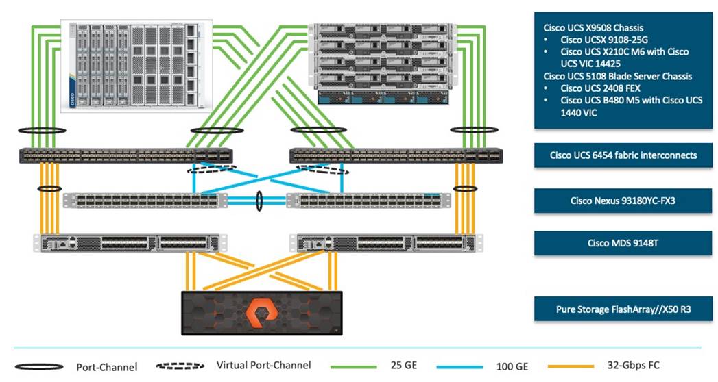
To validate FlashStack for SAP HANA TDI in the required FC-based storage access design, the components are set up as follows:
● Cisco UCS 6454 Fabric Interconnects provide chassis and network connectivity.
● The Cisco UCS X9508 chassis connects to fabric interconnects using Cisco UCSX 9108-25G Intelligent Fabric Modules (IFMs), where four 25 Gigabit Ethernet ports are used on each IFM to connect to the appropriate FI.
● Cisco UCS X210c M6 compute nodes contain fourth-generation Cisco 14425 virtual interface cards.
● The Cisco UCS 5108 Blade server chassis connects to fabric interconnects using Cisco UCS 2408 IOM modules, where four 25 Gigabit Ethernet ports are used on each IOM to connect to the appropriate FI.
● Cisco UCS B480 M5 blade servers contain fourth-generation Cisco 1440 virtual interface cards.
● Cisco Nexus 93180YC-FX3 Switches in Cisco NX-OS mode provide the switching fabric.
● Cisco UCS 6454 Fabric Interconnect 100 Gigabit Ethernet uplink ports connect to Cisco Nexus 93180YC-FX3 Switches in a virtual port-channel (vPC) configuration.
● Cisco UCS 6454 Fabric Interconnects are connected to the Cisco MDS 9148T switches using 32-Gbps Fibre Channel connections configured as a single port-channel (pc) for SAN connectivity.
● The Pure Storage FlashArray//X50 R3 connects to the Cisco MDS 9148T switches using 32-Gbps Fibre Channel connections for SAN connectivity.
● VMware 7.0 U3c ESXi software is installed on Cisco UCS X210c M6 compute nodes and Cisco UCS B480 M5 blade servers to validate the infrastructure.
● Red Hat Enterprise Linux 8.6 for SAP Solutions and SUSE Linux Enterprise 15 SP4 for SAP Applications is installed on Cisco UCS X210c M6 servers and Cisco UCS B480 M5 servers to validate the infrastructure.
● SAP HANA platform edition 2.0 SPS06 is installed as virtual instance or bare metal to validate the infrastructure.
Firmware and Software Revision
Any time that devices are interconnected, interoperability needs to be verified. Verification is particularly important in the storage environment. Every vendor publishes its own interoperability matrices (also known as hardware and software compatibility lists). Cisco UCS is no different in this respect. Of course, full interoperability is much easier to achieve with products from the same vendor as the Cisco Nexus switches and UCS compute because they come from the same engineering organization and are readily available for internal testing.
The different hardware and software compatibility tools are available at the following links:
● Cisco UCS Hardware and Software Interoperability Matrix
● Cisco MDS and Cisco Nexus Interoperability Matrix
● Pure Storage Interoperability Matrix
● Pure Storage FlashStack Compatibility Matrix
In addition to the hardware components, the software product features need to fully integrate with SAP solutions which is confirmed with SAP certifications and SAP notes accordingly:
● Certified and supported SAP HANA hardware
● SAP note 2235581 – SAP HANA: Supported Operating Systems
● SAP note 2937606 – SAP HANA on VMware vSphere 7.0 in production
All firmware and software revisions adhere to Cisco, Pure Storage, VMware, and SAP interoperability lists including SAP notes to determine a fully SAP HANA supported configuration. Table 1 lists the firmware and software revisions used for the solution validation and testing.
Table 1. Firmware and Software Revision
| Component |
Software Revision |
| Fabric Interconnects |
Cisco Intersight Infrastructure Bundle 4.2(2c) |
| Cisco UCS X-Series Server |
Cisco UCS X-Series Server Firmware, revision 5.0(2d) |
| Cisco UCS B-Series M5 Server |
Cisco Intersight Server Bundle, revision 4.2(2d) |
| Cisco VIC enic driver for ESXi |
1.0.45.0 |
| Cisco VIC fnic driver for ESXi |
5.0.0.34 |
| Pure Storage FlashArray//X 50 R3 |
Purity//FA 6.3.7 |
| Pure Storage VASA provider |
3.5 |
| Pure Storage vSphere Plugin |
4.5.2 |
| Cisco Nexus 93180YC-FX3 |
Cisco Nexus 9000 Series NX-OS Release 9.3(10) |
| Cisco MDS 9148T |
MDS NX-OS Release 9.3(2) |
| Cisco Intersight Assist |
Cisco Intersight Virtual Appliance and Assist 1.0.9-499 |
| VMware vSphere 7 |
VMware ESXi 7.0 Update 3i |
| Red Hat |
Red Hat Enterprise Linux 8.6 for SAP Solutions |
| SUSE |
SUSE Linux Enterprise for SAP Applications 15 SP4 |
This document details the step-by-step configuration of a fully redundant and highly available Virtual Server Infrastructure with SAP HANA TDI built on Cisco and Pure Storage components. The focus of this document is infrastructure-as-code (IaC) using the Ansible Automation Platform for consistent and repeatable configuration. This deployment guide builds on the FlashStack Virtual Server Infrastructure with Cisco UCS X-Series and VMware 7.0 U2 deployment guide which details the manual configuration of the environment in the appendix for reference.
High-level naming conventions
While naming conventions are somewhat subjective and depend on your organization’s definition, here are recommendations and naming conventions that have been used successful during the design validation. Use these as examples but modify to fit your needs.
Select the underscore as delimiter for a separation of object suffix/prefix (for example lun_id, name_of_kvm_policy) of variables. It is a best practice using capitalization between words for the variable definition but keep the Ansible variable name in lowercase (for example name_of_kvm_policy: “FlashStack-KVM-Policy”).
Multiple components like the two FlashArray controllers or Cisco MDS switches are available as pair or there are multiple compute nodes which are similarly configured. To distinguish between those hardware components during the configuration they are referenced either with increasing numbers like 01, 02, and so on or with letters like A and B. For example, Cisco Nexus A and Cisco Nexus B identifies the pair of Cisco Nexus switches that are configured.
Some steps require manual configuration on the command line (CLI) to enable device access and to claim devices in Cisco Intersight. These configuration steps include pertinent variables in angle brackets (<< >>) which appear as mandatory part of the command structure, for example:
nexus-A (config) # ntp server <<var_oob_ntp>> use-vrf management
About Ansible
Ansible is an open-source IT automation engine that automates cloud provisioning, configuration management, application deployment, interservice orchestration and other IT needs. Ansible uses small programs called Ansible modules to initiate API calls towards the Cisco NX-OS devices and Cisco Intersight and apply configurations that are defined in playbooks.
By default, Ansible represents what machines it manages using an inventory file that puts all managed compute nodes in groups of your own choosing.
Go to https://docs.ansible.com/ansible/latest/getting_started/index.html for installation requirements for supported control environments.
About NX-API REST
On Cisco Nexus switches, configuration is performed using command-line interfaces (CLIs) that run only on the switch. NX-API REST improves the accessibility of the Cisco Nexus configuration by providing HTTP/HTTPS APIs that:
● Make specific CLIs available outside of the switch.
● Enable configurations that would require issuing many CLI commands by combining configuration actions in relatively few HTTP/HTTPS operations.
NX-API REST supports show commands, basic and advanced switch configuration, and Linux Bash.
For more information about the Cisco Nexus 9000 Series NX-API REST SDK, see https://developer.cisco.com/docs/nx-os-n3k-n9k-api-ref.
About Cisco Intersight RESTful API
Cisco Intersight provides a cloud-based RESTful API to manage Intersight connected targets across multiple data centers. Intersight API requests may be read-only queries with no side-effects or produce modifications of resources. It accepts and returns messages that are encapsulated through JavaScript Object Notation (JSON) documents and uses HTTP over TLS as the transport protocol.
Cisco Intersight provides downloadable SDK packages in multiple programming languages. For a detailed Intersight API overview, see https://intersight.com/apidocs/introduction/overview.
Configuration guideline
In Ansible variables are used to insert a variable into one or multiple places of a playbook instead of manually entering the same value in multiple places or configuration steps manually. The main variable types used during the deployment are host, group, and role variables. The host variables (folder host_vars) keeps YAML files with references for specific devices, for example MDS-A and MDS-B. The group variables (folder group_vars) keeps YAML files with references for groups of devices or all devices. Finally, each role contains role specific description variables (folder default) which typically don’t require changes prior of the Ansible playbook execution.
This document is intended to enable you to fully configure the customer environment. In this process, various steps require you to insert customer-specific naming conventions, IP addresses, and VLAN schemes, as well as to record appropriate MAC addresses. For the deployment as outlined in this guide, Table 2 lists the required VLANs, Table 3 lists the required VSANs, and Table 4 lists the necessary external dependencies.
Table 2. Required VLANs for this deployment.
| VLAN ID |
Name |
Description |
| 2 |
Native-VLAN |
Use VLAN 2 as native VLAN instead of the default VLAN 1. |
| 3072 |
OOB-MGMT-VLAN |
Out-of-band management VLAN to connect management ports for various devices |
| 76 |
IB-MGMT-VLAN |
In-band management VLAN utilized for all in-band management connectivity – for example, ESXi hosts, VM management, and other infrastructure services. |
| 172 |
VM-Traffic |
VMware virtual machine data traffic; use multiple VLANs depending on the SAP HANA requirements. |
| 3319 |
vMotion |
VMware vMotion traffic |
| 10 |
fcoe_vlan_id_on_fi_a |
FCoE VLAN ID for Fabric Interconnect A |
| 20 |
fcoe_vlan_id_on_fi_b |
FCoE VLAN ID for Fabric Interconnect B |
| 223 |
AppServer_VLAN |
SAP Application Server VLAN |
| 221 |
Backup_VLAN |
SAP HANA Backup VLAN |
| 222 |
Client_VLAN |
SAP HANA Client VLAN |
| 224 |
DataSource_VLAN |
SAP HANA DataSource VLAN |
| 225 |
Replication_VLAN |
SAP HANA Replication VLAN |
Out-of-band configuration for the components configured as in-band can be enabled, however this requires additional uplink ports on the 6454 Fabric Interconnects if the out-of-band management is kept on a separate out-of-band switch. A disjoint layer-2 configuration allows a complete separation of the management and data plane networks. This setup requires additional vNICs on each server, which are then associated with the management uplink ports.
Table 3. Required VSANs for this deployment.
| VSAN ID |
Name |
Description |
| 101 |
fcoe_vlan_id_on_fi_a |
VSAN ID of MDS-A switch for boot-from-SAN and SAP HANA storage access |
| 102 |
fcoe_vlan_id_on_fi_b |
VSAN ID of MDS-B switch for boot-from-SAN and SAP HANA storage access |
A pair of VSAN IDs (101 and 102) are configured to provide block storage access for the ESXi or Linux hosts and the SAP HANA data, log, and shared volumes.
Table 4. Virtual Machines for this deployment
| Virtual Machine |
Description |
Host Name |
Customer IP address |
| vCenter Server |
Infrastructure VM management |
vcenter-flashstack.flashstack.local |
|
| Linux |
Infrastructure Linux host |
linux.flashstack.local |
|
| Cisco Intersight Assist |
Cisco Intersight Assist |
imm-assist.flashstack.local |
|
| Ansible Tower |
Ansible Tower automation (optional) |
tower.flashstack.local |
|
Additional infrastructure services like DNS, NTP and file services (NFS, CIFS or HTTPS) are prerequisites for the software installation and configuration.
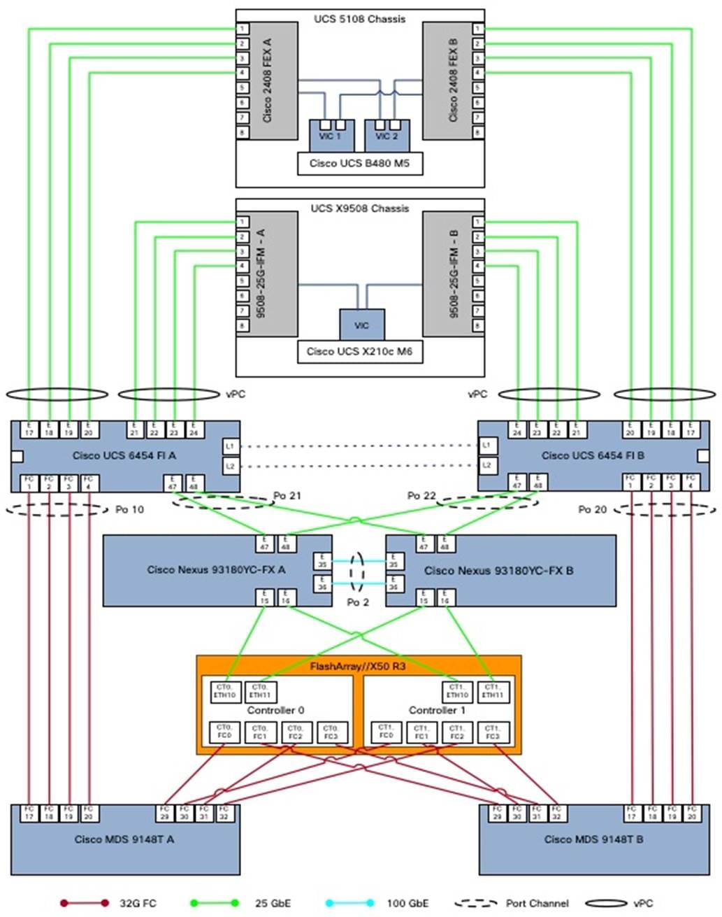
FlashStack cabling
The information in this section provides the cabling reference for the FlashStack hardware components. The cabling diagram in Figure 2 shows the cable connections used in the validation lab setup. This document assumes that out-of-band management ports are plugged into an existing management infrastructure at the deployment site. These interfaces are used in various configuration steps.
The MDS switches connect with a total of eight 32 GB FC links to the Pure FlashArray//X50 R3. Each of the MDS switches connect with two links to each of the two FlashArray//X controllers. A total of eight 32 GB FC links connects the MDS switches and the Cisco Fabric Interconnects with port channel configured.
Each FlashArray//X controller connects with two 10/25 GbE links to both Nexus switches enabling NFS file service for the SAP HANA shared directory in case of an SAP HANA scale-out solution is required. Two 25 GbE links connect from each Nexus switch to both Fabric Interconnects with port channel configured.
| Tech tip |
| For SAP HANA scale-out implementations consider switching from the previous Windows File Service (WFS) to FA File Services, which is the native implementation of Network Attached Services (NAS) within the FlashArray Purity operating system. See the link in the appendix for further information. |
Additional 1Gb management connections are required for an out-of-band network switch configuration that sits apart from the FlashStack infrastructure. Each Cisco UCS Fabric Interconnect and Cisco Nexus switch connects to the out-of-band network switch, and each FlashArray controller connects to the out-of-band network switch as well. Layer 3 network connectivity is required between the out-of-band (OOB) and in-band (IB) management subnets.
The design uses FC for boot and datastore access. It is possible to split the ports on the FlashArray//X controller between SCSI-FC and FC-NVMe for different, non-SAP HANA workloads, but each port can only function either as an SCSI-FCP or FC-NVMe port.
Automated Solution Deployment
This chapter contains the following:
● Automation execution environment
● FlashStack deployment using Ansible playbooks
● Cisco Intersight configuration
● Cisco Nexus network configuration
● FlashStack//X initial storage configuration
● Cisco MDS switch configuration
● FlashStack storage configuration
● VMware vSphere 7.0 U3i installation and configuration
● FlashStack VMware vSphere Distributed Switch (vDS)
● Configure vSphere Cluster Services
● Enable EVC on the VMware cluster
● Add and configure additional VMware ESXi hosts in vCenter
● Pure Storage vSphere Client Plugin
Instructions for installing a management workstation are not included in this document, but the basic installation and configuration steps to setup Ansible are highlighted.
The following general prerequisites are required:
● Create a Cisco Intersight account on https://intersight.com and optionally an organization for the deployment.
● All hardware must be physically racked, cabled, powered, configured with the management IP addresses, and claimed in Cisco Intersight.
● Basic Ansible knowledge. Refer to Getting started with Red Hat Ansible for further details on Ansible.
● The automation execution environment requires Internet access, the installation of Git and access to the GitHub repository. Ansible playbooks used for this deployment guide have been cloned and extended from the public repositories, located at: https://github.com/ucs-compute-solutions/FlashStack_IMM_Ansible.
● Management LAN access from the automation execution environment.
● Variables needs to be changed from default reflecting the customer environment prior of the execution of an Ansible playbook.
● Day-2 configuration tasks such as adding datastores or virtual machines can be performed manually or within Cisco Intersight Infrastructure Service and Cloud Orchestrator.
The automation workflow uses a GitHub repository with Ansible playbooks and roles to configure all components of FlashStack and install the VMware software components as well as individual virtual machines including SAP HANA.
This deployment guide divides the workflow into eight individual workflows which need to be executed one after the other.
● Setup of the automation execution environment.
● Cisco Nexus switch configuration.
● Pure Storage FlashArray//X configuration.
● Cisco UCS chassis and compute node configuration.
● Cisco MDS switch configuration.
● VMware vSphere 7.0 installation.
● Virtual machine installation and configuration.
● SAP HANA installation.
Automation execution environment
The installation steps performed in this section prepare the automation execution environment on a Red Hat Enterprise Linux 8 host for solution deployment to support the automation of the Intersight managed FlashStack solution using Ansible playbooks.
The following Ansible collections are required to manage and automate Cisco Intersight environments:
● Cisco Intersight Ansible Collection (https://github.com/CiscoDevNet/intersight-ansible)
● Cisco NX-OS Ansible Collection (https://galaxy.ansible.com/cisco/nxos)
● Pure Storage FlashArray Ansible Collection (https://galaxy.ansible.com/purestorage/flasharray)
● VMware Ansible Collection (https://galaxy.ansible.com/community/vmware)
● SAP module collection for Ansible (https://github.com/sap-linuxlab/community.sap_libs)
Procedure 1. Automation Execution Environment
Step 1. Open a terminal session as root user.
Step 2. Verify the required python version is installed.
python --version
yum install python39
Step 3. Configure the unversioned python command.
alternatives -set python /usr/bin/python3.9
Step 4. Upgrade pip and setuptools to the most current version
python -m pip install --upgrade pip setuptools
Step 5. (Optional) Create a new user for the automation activities and change the user context to the new user.
Step 6. Install the Ansible package (https://ansible.com) for the current user.
python -m pip install --user ansible
Step 7. Add the Ansible command line completion.
python -m pip install --user argcomplete
activate-global-python-argcomplete --user
Step 8. Prepare virtual environment using pipenv (https://pipenv-fork.readthedocs.io/en/latest).
python -m pip install --user pipenv
Step 9. Create a project folder and navigate to the project folder.
Step 10. Create a virtual environment within the project folder.
pipenv install
pipenv shell
Step 11. (Optional) Install linter to analyze your source code.
pipenv install ansible-lint
pipenv install yamllint
Step 12. Install Ansible LibSSH.
pipenv install ansible-pylibssh
Step 13. Install required collections from Ansible Galaxy.
ansible-galaxy collection install cisco.intersight
ansible-galaxy collection install cisco.nxos
ansible-galaxy collection install purestorage.flasharray
ansible-galaxy collection install community.vmware
ansible-galaxy collection install community.sap_libs
| Tech tip |
| When installing a collection from Ansible Galaxy, it will not be upgraded automatically when you upgrade the ansible package. To upgrade the collection to the latest available version, run the following command within your virtual environment: # ansible-galaxy collection install <collection-name> --upgrade |
Step 14. Define your git user (the same name and email you use for GitHub (https://github.com).
git config --global user.name “your name”
git config --global user.email “your@mail.com”
Procedure 2. Clone GitHub repository
As a starting point, clone the GitHub repository from the public collection () to a new, empty folder within your automation execution environment. Cloning the repository creates a local copy, which is then used to run the playbooks that have been created for this solution.
Step 1. Change to the project folder and open the virtual environment.
pipenv shell
Step 2. Clone the GitHub repository with the following command:
git clone https://github.com/ucs-compute-solutions/FlashStack_IMM_Ansible.git
Step 3. Change directory to the new folder created.
cd FlashStack_IMM_Ansible
Procedure 3. Cisco Intersight API configuration
The Ansible playbook execution requires an API key and secrets file for authentication against Cisco Intersight. Sign into Cisco Intersight (https://intersight.com) and perform the following steps:
Step 1. From the top drop-down list select System.
Step 2. In the Settings - General section scroll down and select API keys.
Step 3. Click Generate API key.
Step 4. Provide an API key description and select API key for OpenAPI schema version 2 as API key purpose.
Step 5. Select generate.
Step 6. In the new window select the save secret key to text file icon to download the SecretKey.txt file.
Step 7. Copy the API Key ID to your clipboard and modify the api_key_id value in the group variable file groups_var/all.yml.
Step 8. Close the window.
Step 9. Copy the SecretKey.txt file to the root folder of the cloned repository, FlashStack_IMM_Ansible.
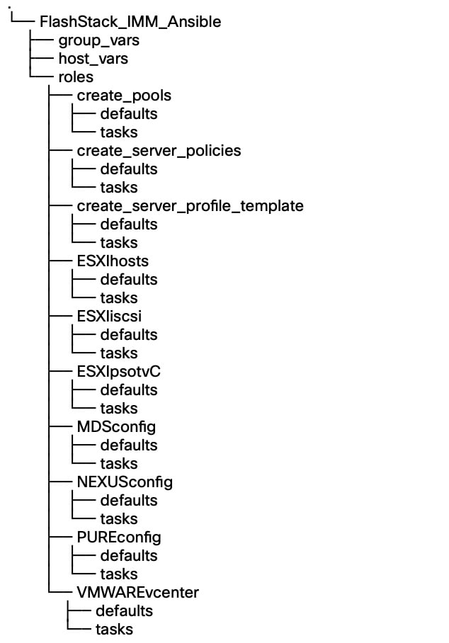
FlashStack deployment using Ansible playbooks
The following sections explain the installation and configuration of all infrastructure layers of the FlashStack for SAP HANA TDI solution. The Ansible playbooks are the instruction manuals and are used to manage configurations of any deployments to remote machines. Below directory structure contains the configuration files, roles, and tasks used by the playbooks in the directory root folder.
Before running any of the Ansible playbooks it is key to modify the configuration files first explained in the specific section throughout this guide. The following variable configuration files need to be changed:
● inventory - contains the variables such as device IP addresses and authentication details.
● groups_vars/all.yml - contains the required input for Intersight, Nexus and MDS configuration, VLAN IDs, ESXi configuration, etc.
● host_vars/mdsA.yml - contains port channel and zoning configuration for MDS A.
● host_vars_/mdsB.yml - contains port channel and zoning configuration for MDS B.
● host_vars/n9kA.yml - contains vPC and interface configuration for Nexus A.
● host_vars/n9kB.yml - contains vPC and interface configuration for Nexus A.
● roles/MDSconfig/defaults/main.yml - contains interface and feature configuration.
● roles/NEXUSconfig/defaults/main.yml - contains interface and feature configuration.
● roles/PUREconfig/vars/main.yml - contains FA URL, authorization, and interface configuration.
Cisco Intersight configuration
The Cisco Intersight playbooks in this repository perform the following functions:
● Create various pools and policies required to setup a server profile template.
● Create a Fibre Channel based profile template.
After successful execution of the playbooks, one or many server profiles can be easily derived and attached to the compute node from the Cisco Intersight dashboard.
The Ansible roles and playbooks are provide “as is” and can be modified or extended as required. For example, the is currently no role to create an organization if the one you configure is missing. It is possible to create it before the Ansible playbooks are executed and the hardware components are claimed, or this other way around and prepare Intersight and claim the hardware after.
If you want to add additional roles, follow the same syntax, and review the Cisco Intersight API documentation for the resource path and default parameters to set. If you require a role to verify the organization specified in the configuration file, follow these steps:
Step 1. Create a folder intersight_organization, with subfolder defaults and tasks.
Step 2. In the subfolder tasks create a new file create_org.yml with the following content:
---
- name: "Create Intersight organization"
vars:
api_info: &api_info
api_private_key: "{{ api_private_key }}"
api_key_id: "{{ api_key_id }}"
api_uri: "{{ api_uri | default(omit) }}"
validate_certs: "{{ validate_certs | default(omit) }}"
state: "{{ state | default(omit) }}"
cisco.intersight.intersight_rest_api:
<<: *api_info
resource_path: /organization/Organizations
query_params:
$filter: "Name eq '{{ org_name }}'"
api_body: {
"Name": "{{ org_name }}",
"Description": "{{ description_of_organization }}",
Tags: [{Key: "configmode", Value: "ansible"}, {Key: "prefix", Value: "{{ prefix }}"}]
}
register: intersight_org
Step 3. In the same subfolder, create a new file main.yml with the following content:
---
- include_tasks: create_org.yml
Step 4. In the subfolder defaults, create a new file main.yml to describe the role default variables with the following content:
---
org_resource_group: "default"
description_of_organization: 'FlashStack for SAP HANA'
Step 5. Create a new playbook, create_org.yml, in the root folder of the Ansible automation code to call the new role just created.
Procedure 1. Modification of Ansible configuration files
The majority of the required configuration variables are present in the group variable file group_vars/all.yml.
Step 1. Modify the all.yml configuration file and adjust the following variables:
Basic Cisco Intersight configuration:
org_name - Intersight organization name, must match the organization the hardware is claimed into.
prefix - Prefix added to the pool/policy/profile configuration names for easy identification.
configure_iscsi - Set to “false,” this configuration is unsupported with SAP HANA.
configure_fc - Set to “true” to configure a FC-based FlashStack solution design.
configure_fc_nvme - Set to “false,” this configuration is unsupported with SAP HANA.
vic_type - set to 4G for 4th gen VICs or 5G for 5th gen VICs.
uuid_prefix and size - Configure the chassis UUID pool.
Pool configuration:
ip_pool_start_for_management_access - Management Access IP pool start address-
size_of_ip_pool_for_management_access - Specify the IP address pool size.
gateway_mgmt - Specify the management gateway IP address.
netmask_mgmt - Specify the netmask for the management IP pool.
primary_dns_mgmt - Provide the primary DNS name server IP address.
secondary_dns_mgmt - Provide the secondary DNS name server IP address.
mac_pool_start_on_fi_a - Separate MAC address pools for fabric-A and fabric-B
mac_pool_start-on_fi_b - Separate MAC address pools for fabric-A and fabric-B
wwnn_pool_start - FC pool start MAC address.
wwnn_pool_size - FC WWNN pool size
wwnn_pool_start_on_san_a - FC WWNN pool start MAC address for fabric-A.
wwnn_pool_start_on_san_b - FC WWNN pool start MAC address for fabric-B.
Policies configuration:
vlan_for_cimc_access - VLAN for CIMC access.
password_for_local_user - Password of local admin user in Local User Policy.
allowed_vlans_for_mgmt_vnic - VLAN details of vNIC assigned to virtual switches for management.
allowed_vlans_for_vds_vnic - VLAN details for vNIC assigned to vMotion and VM traffic.
Fibre Channel and SAN connectivity configuration
fcoe_vlan_id_SAN_A - VLAN ID for FC network policy SAN A.
vsan_id_SAN_A - VSAN ID for FC network policy SAN A.
fcoe_vlan_id_SAN_B - VLAN ID for FC network policy SAN B.
vsan_id_SAN_B - VSAN ID for FC network policy SAN A.
san_boot_target_wwpn - Target WWPN names.
Step 2. Save and quit the configuration file.
Step 3. Run the Ansible playbook to create the IP and MAC pools:
$ ansible-playbook create_pools.yml
…
PLAY RECAP **************************************************************************************
localhost: ok=15 changed=9 unreachable=0 failed=0 skipped=1 rescued=0 ignored=0
Step 4. Run the Ansible playbook to setup the Intersight policies:
$ ansible-playbook create_server_policies.yml
PLAY RECAP **************************************************************************************
localhost: ok=54 changed=26 unreachable=0 failed=0 skipped=17 rescued=0 ignored=0
Step 5. Run the Ansible playbook to create the Intersight server profile template:
$ ansible-playbook create_server_profile_template.yml
PLAY RECAP **************************************************************************************
localhost: ok=14 changed=1 unreachable=0 failed=0 skipped=3 rescued=0 ignored=0
Step 6. Logon to Cisco Intersight (https://intersight.com).
Step 7. Select Infrastructure Service and from the left menu Configure > Templates.
Step 8. If you have many templates already, filter for the prefix configured in step 1.
Step 9. Select the ellipses menu at the end of the displayed template to open the menu and select Derive Profiles.
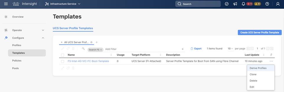
Step 10. In the Server Assignment section keep assign now selected and mark the servers the template should be assigned to. Click Next to proceed.
Step 11. In the details screen, keep or change the auto-generated profile names. Click Next to proceed.
Step 12. Review the summary screen and select Derive to drive the server profiles from the template.
Step 13. In the left menu go to Configure > Profiles and select UCS Server Profiles from the top menu.
Step 14. The UCS server profiles are not deployed. Select the three-dot menu on the right side of the profile and select Deploy.
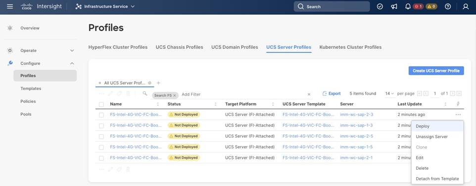
Step 15. Wait until the status changes to ok. Then select Operate > Servers in the left menu and review the servers.
Note: The BIOS policy activates all C-states which is the best practice for the virtual server infrastructure. However, if a service profile is required for a bare-metal SAP HANA installation, it is recommended to create a new BIOS policy and disable all C-states deeper than C1/C1E for optimal SAP HANA performance.
Cisco Nexus network configuration
First ensure the FlashStack cabling is complete and the initial configuration of the Cisco Nexus switches including setup of the management IP address is done. The following procedure describes the basic configuration of the Cisco Nexus switches for use in a FlashStack for SAP HANA TDI environment. The procedure has been validated against the Cisco Nexus C93180YC-FX switches running NX-OS release 9.3(10) but executes similarly when executed against Cisco Nexus C93360YC-FX2 switches using 100G ports.
Procedure 1. Modification of Ansible configuration files
Before running the Nexus configuration Ansible scripts, modify them according to your specific environment.
Step 1. Modify the host file inventory and enter the host IP addresses and the user and password for both Nexus switches in the file section titled [nexus]. Save and quit the file.
The following modifications are required in the group variables file groups_var/all.yml.
Step 2. Enter the IP addresses of your DNS and NTP servers and update the DNS domain name.
Step 3. Adjust the VLAN names. The following VLANs have been added as part of the validation:
appserver_vlan_name: ‘SAP-AppServer-VLAN’ # VLAN for SAP Application Server network
backup_vlan_name: ‘HANA-Backup-VLAN’ # VLAN for SAP HANA Backup network
client_vlan_name: ‘HANA-Client-VLAN’ # VLAN for SAP HANA Client network
datasource_vlan_name: ‘HANA-Datasource-VLAN’ # VLAN for SAP HANA Datasource network
replication_vlan_name: ‘HANA-Replication-VLAN’ # VLAN for SAP HANA Replication network
Step 4. Extend the entries for the variable vlan_list by the VLANs added in step 3 including their respective VLAN ID. Follow the same formatting structure. Change the pre-configured VLAN IDs as required and delete/comment the ISCSI A and B VLANs in the list.
Step 5. Modify the value of variable all_vlans_list with the VLANs configured in the previous steps.
Step 6. Modify the value of variable mgmt_vlans_list. Save and quit the group variables configuration file.
The following modifications are required in the Nexus host group files host_vars/n9kA.yml and n9kB.yml accordingly.
Step 7. Modify the vPC variable values for vpc_source and vpc_destination.
Step 8. Enter the interfaces and interface descriptions for the uplink, peer-link, the fabric A and B links, and the storage iSCSI interfaces. If the environment has four iSCSI connections to the storage controllers, add the additional interfaces and their description to the storage_interface_list. Save and quit the host variable configuration file.
The following modifications like vPC domain ID, port channels details and Cisco Nexus features are required in the role variables file roles/NEXUSconfig/defaults/main.yml.
Step 9. Modify the global NTP server IP addresses and the NTP distribution VLAN and gateway.
Step 10. Modify and add all required port channel details.
Step 11. Specify the vPC domain ID. Save and quit the role variable configuration file.
Procedure 2. Configure Cisco Nexus switches
Once the configuration steps are complete, run the Cisco Nexus switch Ansible playbook. You can limit the tasks executed in the playbook by modifying the main.yml file in folder ../roles/NEXUSconfig/tasks.
| Tech Tip |
| To run a backup of the NX-OS running config before and after the playbook run, include the task save_nxos_config.yml in the main.yml file in folder ../roles/NEXUSconfig/tasks before the configuration tasks. In addition, change the save_when variable value from modified to always within the save_nxos_config.yml file. |
Step 1. SSH to each Nexus switch to add the RSA keys.
$ ssh admin@<Nexus-A-mgmt-IP>
$ ssh admin@<Nexus-B-mgmt-IP>
Step 2. Run the Nexus Ansible playbook:
$ ansible-playbook Setup_Nexus.yml -i inventory
PLAY [Configure Nexus switches] ********************************************************************
TASK [nexus_config : include_tasks] ********************************************************************
included: ~/FlashStack_IMM_Ansible/roles/nexus_config/tasks/initiate_nxos_config_backup.yml for n9kA, n9kB
TASK [nexus_config : Backup of the current running config before deploying changes to the device] ******
changed: [n9kA]
changed: [n9kB]
TASK [nexus_config : include_tasks] ********************************************************************
included: ~/FlashStack/FlashStack_IMM_Ansible/roles/nexus_config/tasks/save_nxos_config.yml for n9kA, n9kB
TASK [nexus_config : Save the Nexus Configuration] *****************************************************
ok: [n9kA]
ok: [n9kB]
PLAY RECAP ***************************************************************************************
n9kA: ok=4 changed=1 unreachable=0 failed=0 skipped=0 rescued=0 ignored=0
n9kB: ok=4 changed=1 unreachable=0 failed=0 skipped=0 rescued=0 ignored=0
Step 3. Logon to the Cisco Nexus Switch command line (CLI) and verify the configuration is complete and according to the requirements before proceeding with the next section.
FlashStack//X initial storage configuration
Skip this section if a Pure Storage implementation engineer performed the initial configuration of the FlashArray//X.
Procedure 1. Configure the FlashArray//X storage
Step 1. Modify the host file inventory and enter the host IP addresses of the FlashArray in the file section titled [FlashArray]. Save and quit the file.
Step 2. Modify the following variables in the group variable file group_vars/all.yml.
initial_fa_config: “yes” - uncomment the line to perform the initial FlashArray//X configuration.
configure_fc: “true” - Comment this line for the initial FlashArray//X configuration and enable it again after the Cisco MDS configuration is complete.
Step 3. Modify the following variables in the Pure Storage variable configuration file ../roles/PUREconfig/vars/main.yml. Only change required information and keep other values like SMTP or LDAP integration details on default if not required.
fa_url - FlashArray IP address
fa_api_token - Generate a token in Purity//FA
array_name - FlashArray name
interfaces - IP address and port of all interfaces which require configuration
dns_address - DNS IP address
dns_domain - DNS domain name
ntp_server - NTP server
Step 4. SSH to the FlashArray//X to add the RSA key.
$ ssh pureuser@<fa_url>
Step 5. When the configuration changes are complete, run the Ansible playbook:
$ ansible-playbook Setup_Pure.yml -i inventory
Cisco MDS switch configuration
Make sure the initial configuration of the Cisco MDS switches including the setup of the management IP address is done. The following procedure describes the basic configuration of the Cisco MDS switches for use in a FlashStack for SAP HANA TDI environment. The procedure has been validated against the Cisco MDS 9148T switches running NX-OS release 9.3(2), the Cisco recommended MDS switch release at the time of this validation.
Procedure 1. Modification of Ansible configuration files
Before running the MDS configuration Ansible scripts, modify them according to your specific environment.
Step 1. Modify the host file inventory and enter the host IP addresses and the user and password for both MDS switches in the file section titled [mds]. Save and quit the file.
The following modifications are required in the group variables file groups_vars/all.yml.
Step 2. Adjust the VSAN parameters below parameter vsan_list, like VSAN name, VSAN ID and FCoE VLAN ID.
Step 3. Capture the FC WWPNs from Purity//FA and adjust the WWPNs in the configuration file. Save and quit the file.
The following modifications are required in the host variable files host_vars/mdsA.yml and mdsB.yml.
Step 4. Modify the port channel ID and the port channel description.
Step 5. Modify the Zoneset and Zone names.
Step 6. Change and adapt the device alias list according to your requirements.
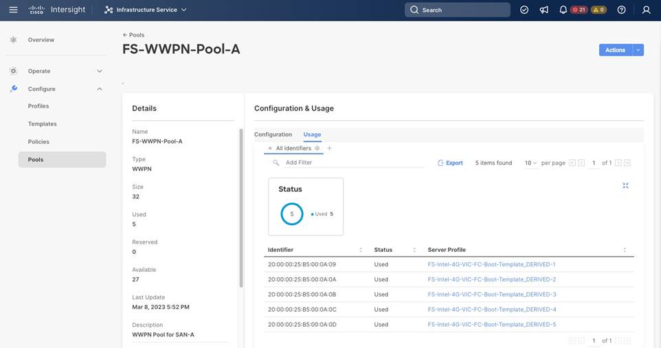
Step 7. Review the required identifiers from Intersight. Click Infrastructure Service > Configure > Pools. Select both WWPN-Pools (<prefix>-WWPN-Pool-<A|B>) one after the other to review the used identifiers.
Step 8. Change the storage interfaces according to your requirements.
Step 9. Change the UCS interface list according to your requirements and add UCS C-Series server if applicable. Save and quit the file.
Step 10. Consider changing the timezone and summer-time settings according to your needs in the roles default variable file roles/MDSconfig/defaults/main.yml.
Procedure 2. Configure Cisco MDS switches
Once the configuration steps are complete, run the Cisco MDS switch Ansible playbook. You can limit the tasks executed in the playbook by modifying the main.yml file in folder ../roles/MDSconfig/tasks.
| Tech Tip |
| To run a backup of the NX-OS running config before and after the playbook run, include the task save_mds_config.yml in the main.yml file in folder ../roles/MDSconfig/tasks before the configuration tasks. In addition, change the save_when variable value from modified to always within the save_mds_config.yml file. |
Step 1. SSH to each MDS switch to add the RSA keys.
$ ssh admin@<MDS-A-mgmt-IP>
$ ssh admin@<MDS-B-mgmt-IP>
Step 2. Run the Nexus Ansible playbook:
$ ansible-playbook Setup_MDS.yml -i inventory
PLAY [Configure MDS switching] ************************************************************************************
TASK [mds_config : include_tasks] ************************************************************************************
included: ~/FlashStack/FlashStack_IMM_Ansible/roles/mds_config/tasks/save_mds_config.yml for mdsA, mdsB
TASK [mds_config : Save the MDS Configuration] ***********************************************************************
changed: [mdsA]
changed: [mdsB]
PLAY RECAP ************************************************************************************
mdsA: ok=2 changed=1 unreachable=0 failed=0 skipped=0 rescued=0 ignored=0
mdsB: ok=2 changed=1 unreachable=0 failed=0 skipped=0 rescued=0 ignored=0
Step 3. Login to the Cisco MDS Switch command line (CLI) and verify the configuration is complete and according to the requirements before proceeding with the next section.
FlashStack storage configuration
After the initial configuration is complete, continue with the FlashArray//X storage configuration.
Procedure 1. Configure FlashStack storage
Step 1. Modify the host file inventory and enter the host IP addresses of the FlashArray in the file section titled [FlashArray]. Save and quit the file.
Step 2. Modify the following variables in the group variable file group_vars/all.yml.
initial_fa_config: “yes” - Comment the line to not perform another initial FlashArray//X configuration.
configure_fc: “true” - Uncomment the variable as the Cisco MDS configuration is complete by now.
Step 3. Modify the following variables in the Pure Storage variable configuration file ../roles/PUREconfig/vars/main.yml. Only change required information and keep other values like SMTP or LDAP integration details on default if not required.
fa_url - FlashArray IP address
fa_api_token - Generate a token in Purity//FA
array_name - FlashArray name
interfaces - IP address and port of all interfaces which require configuration
dns_address - DNS IP address
dns_domain - DNS domain name
ntp_server - NTP server
esx_cluster_fcp - Host group name
esx_hosts_fc - Host name list with host PWWNs.
Step 4. SSH to the FlashArray//X to add the RSA key.
$ ssh pureuser@<fa_url>
Step 5. When the configuration changes are complete, run the Ansible playbook:
$ ansible-playbook Setup_Pure.yml -i inventory
VMware vSphere 7.0 U3i installation and configuration
This section provides instructions to install VMware ESXi 7.0 U3i in the FlashStack environment. After the procedures are complete, a minimum of three ESXi hosts will be provisioned and started.
Several installation methods exist to install ESXi in a VMware environment. These procedures focus on how to use Ansible for automatic deployment, but the installation can be performed manually as well using the built-in keyboard, video, mouse (KVM) console and virtual media features in Cisco Intersight to map remote installation media to individual servers and connect to their boot logical unit numbers (LUNs).
The Cisco custom VMware ESXi ISO image is available here: https://customerconnect.vmware.com/downloads/details?downloadGroup=OEM-ESXI70U3-CISCO&productId=974 and includes already the following drivers, components and tools:
● nenic-ens 1.0.6.0-1OEM.700.1.0.15843807
● nenic 1.0.45.0-1OEM.700.1.0.15843807
● Cisco-nfnic 5.0.0.37-1OEM.700.1.0.15843807
● CIS-ucs-tool-esxi 1.2.2-1OEM
Procedure 1. Modification of Ansible configuration files
Before running the MDS configuration Ansible scripts, modify them according to your specific environment.
Step 1. Modify the host file inventory and enter the user and password in the file section titled [vmware:vars].
Step 2. In section [esxi_fc] add the ESXi hostnames, vMotion IP address and netmask. Save and quit the file.
The following modifications are required in the group variables file groups_vars/all.yml.
Step 3. Change the ESXi admin username (esxi_username) and password (esxi_password).
Step 4. Provide the vCenter hostname (vcenter_hostname) and login credentials (vcenter_username, vcenter_password).
Step 5. Adapt the vCenter Domain Controller name and vCenter cluster name (vcenter_dc, vcenter_cluster).
Step 6. If your configuration of the vMotion VLAN ID is different to 3319, change the id in vMotion_vlan_list and vds_lan_list.
Step 7. If your configuration of the VM-traffic VLAN ID is different to 1032, change the id in vds_vlan_list. Save and quit the file.
The following modifications are required in the ESXIhosts variable file roles/ESXIhosts/defaults/main.yml.
Step 8. Provide the URLs to access the ESXi driver installation bundle and UCS tools. Save and quit the file.
Procedure 2. VMware ESXi host installation
Step 1. When the configuration changes are complete, run the Ansible playbook:
$ ansible-playbook Setup_ESXi.yml -i inventory
The remaining steps are manual steps required from the VMware ESXi host client web interface.
| Tech tip |
| By default, the MAC address of the management VMkernel port vmk0 is the same as the MAC address of the Ethernet port it is placed on. If the ESXi host’s boot LUN is remapped to a different server with a different MAC address, a MAC address conflict will occur because vmk0 will retain the assigned MAC address unless the ESXi system configuration is reset. |
Step 2. (Optional on all ESXi hosts part of the solution) Reset VMware ESXi host VMkernel port MAC address.
Step 3. Open the vKVM of the ESXi host through Intersight. Select CTRL + Alt + F1 to access the VMware console command line and login as root.
Step 4. Execute esxcfg-vmknic -l to get a detailed listing of interface vmk0. The port should be part of the “Management Network” port group. Note down the IP address and netmask of vmk0.
Step 5. To remove the vmk0, execute the command: esxcfg-vmknic -d “Management Network”.
Step 6. Re-add vmk0 with a random MAC address. Execute the command: esxcfg-vmknic -a -I <vmk0-ip> -n <vmk0-netmask> “Management Network”.
Step 7. Verify vmk0 has been added with a random MAC address and is tagged as management interface executing esxcfg-vmknic -l.
Step 8. Press Ctrl-D to log out and Ctrl + Alt + F2 to return to the VMware ESXi menu.
Step 9. Open a web browser on the management workstation and navigate to the VM-Host-Infra-FCP-01 management IP address.
Step 10. Provide your username and password and login.
Step 11. Decide whether to join the VMware Customer Experience Improvement Program and click OK.
Step 12. Confirm the virtual switch configuration and select networking - vSwitch0.
Step 13. Click Edit Settings and confirm the MTU is set to 9000.
Step 14. Expand NIC teaming. In the failover order section, confirm vmnic0 and vmnic1 are marked active.
Step 15. Confirm the port group configuration and select networking - port groups.
Step 16. Confirm the Inbound and Outbound management network groups as well as the vMotion port group exist with their respective VLAN ID.
Step 17. Select host - manage - system. In the center pane select Time & date.
Step 18. Confirm the NTP server settings and the service policy is start and stop with host.
Step 19. Select host - manage - hardware. In the center pane select Power Management.
Step 20. Confirm the power policy is set to high performance.
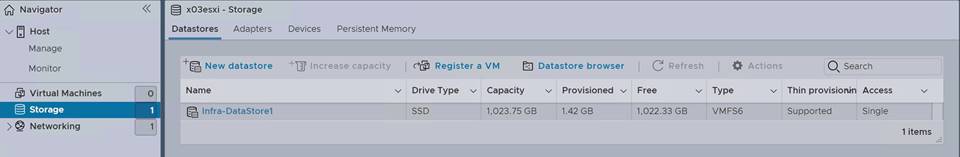
Step 21. Select storage - datastores and click New datastore to add a new datastore.
Step 22. In the new window select Create new VMFS datastore and click Next.
Step 23. Provide a datastore name and select the FA//X LUN which will be used for the datastore.
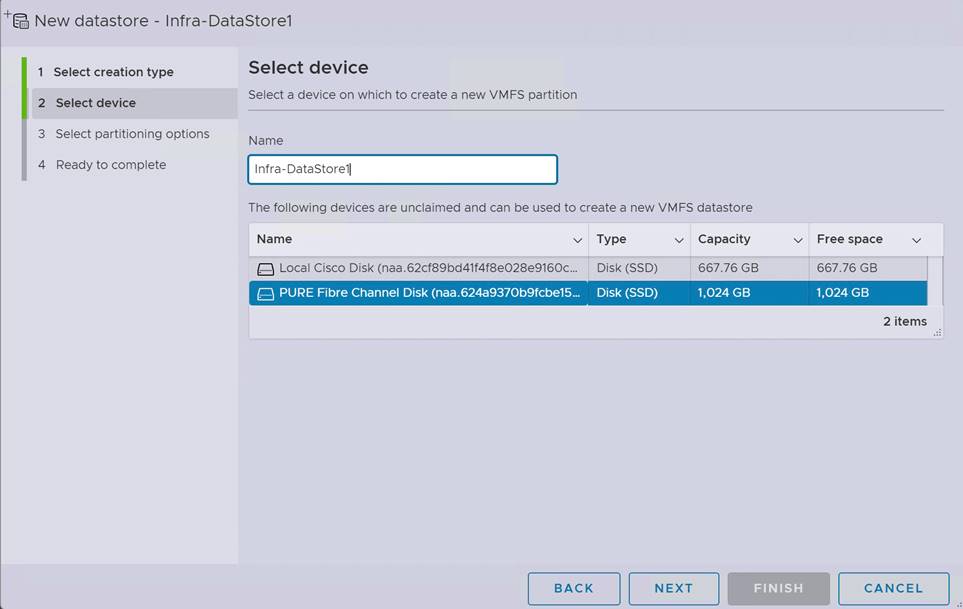
Step 24. Click Next. Keep “use full disk” and click Next.
Step 25. In the final screen click Finish and confirm the warning. The datastore appears in the datastore list.
Step 26. Configure the other ESXi hosts using VMware vCenter 7.
VMware vCenter 7.0 U3i installation and configuration
This section provides instructions to install VMware vCenter 7.0 U3i in the FlashStack environment. After the procedures are complete, a minimum of three ESXi hosts will be provisioned and started.
Several installation methods exist to install vCenter in a VMware environment. These procedures focus on how perform the installation manually, but the installation can be performed using Ansible for automatic deployment as well.
Procedure 1. Install the VMware vCenter server appliance.
The VCSA deployment consists of two stages; install and configuration.
Step 1. Download the VMware vCenter server 7.0U3i Appliance ISO image from: https://customerconnect.vmware.com/downloads/details?downloadGroup=VC70U3H&productId=974&rPId=95488.
Step 2. Mount the ISO image as disk on the management workstation.
Step 3. In the mounted directory, navigate to the vcsa-ui-installer directory and start the installer from the suitable subfolder (lin64, mac, win32) within this directory.
Step 4. Click Install to start the vCenter Server Appliance deployment wizard.
Step 5. In the Introduction screen click Next.
Step 6. Read the license agreement and accept the terms of the license agreement and click Next.
Step 7. In the vCenter Server deployment target screen, provide the ESXi host name or IP address of the first ESXi host configured above. Provide the username (root) and password and click Next.
Step 8. Accept the certificate warning with Yes.
Step 9. Enter the appliance VM name and password details in the Setup vCenter Server VM screen. Then click Next.
Step 10. Select the deployment size of your choice. For this CVD we select small with default storage size which is the minimum requirement for production environments. Then click Next.
Step 11. Select the Infra-DataStore1 as storage location and click Next.
Step 12. In the Configure network settings screen, configure the following settings:
● Select the inbound management network
● IP version IPv4
● IP assignment static
● FQDN: <vcenter-fqdn>
● IP address: <vcenter-ip>
● Subnet mask or prefix length: <vcenter-subnet-mask>
● Default gateway: <vcenter-gateway>
● DNS servers: <dns-server1>, <dns-server2>
Step 13. Click Next.
Step 14. Review all values and click Finish to start the stage 1 installation process.
Step 15. When the installation is complete, click Continue to move to stage 2.
Step 16. In the vCenter Server Configuration screen, enable time synchronization with the NTP servers. Enter the NTP servers.
Step 17. Enable SSH access and click Next.
Step 18. Complete the SSO configuration using the domain vsphere.local or your organization’s SSO domain. Click Next.
Step 19. Decide whether you like to join the VMware’s customer experience improvement program and click Next.
Step 20. Review the configuration and click Finish to set up the vCenter server. Click OK to start stage 2.
Step 21. When the installation is complete, click Close. Eject or unmount the VCSA installer ISO image.
Procedure 2. Adjust vCenter CPU settings.
For vCenter deployment sizes small or larger, it is possible the VCSA’s CPU setup does not match the Cisco UCS server CPU hardware configuration. The Cisco UCS M6 X-Series server is a 2-socket server, but the vCenter appliance configuration sets up a 4-socket server. To avoid issues in the VMware ESXi cluster admission control, change the setting to apply to the 2-socket server:
Step 1. Open a web browser and navigate to the VM-Host-Infra-FCP-01 management IP address.
Step 2. Provide your username and password and login.
Step 3. Select Virtual Machines - VMware vCenter Server and power off the VM.
Step 4. After the VM is powered off, click Edit in the center pane.
Step 5. Expand the CPU entry and change Cores per Socket to 2 sockets.
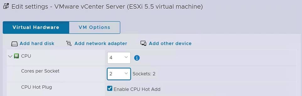
Step 6. Click Save and power on the VM.
Procedure 3. Setup VMware vCenter server.
Step 1. Navigate to https://<vCenter Server IP>:5480 to open the VMware vCenter Server management web frontend.
Step 2. Login to the VMware vCenter Server Management frontend using the root user credentials.
Step 3. Select Time and confirm time zone and time synchronization.
Step 4. Select Administration and adjust the root user credentials according to your security policies.
Step 5. Consider configuring a backup schedule and backup location.
Step 6. Logout from the management frontend.
Create a virtual data center that contains all the inventory objects required to complete a fully functional environment for operating virtual machines.
Step 7. Navigate to https://<vCenter FQDN> and select Launch vSphere Client (HTML5).
Step 8. Login to the VMware vSphere client using the SSO (administrator@vsphere.local) user credentials.
Step 9. Navigate to Inventory > Hosts and Clusters.
Step 10. Right-click the vCenter server object and select New Datacenter.
Step 11. Enter a data center name (FlashStack-DC) and click OK.
A cluster is a group of hosts. When a host is added to the cluster, the resources of the host become part of the cluster resources. The cluster manages the resources of all hosts part of the cluster. Prerequisite are all hosts have the same ESXi version and patch level, and no host have a manual network configuration.
Step 12. Navigate to Inventory > Hosts and Clusters.
Step 13. Right-click the data center (FlashStack-DC) and select New Cluster.
Step 14. Enter a cluster name (FlashStack-Management). Select vSphere DRS and vSphere HA.
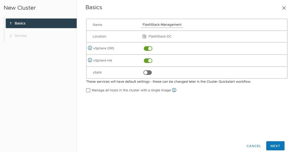
Step 15. Click Next and review the cluster details.
Step 16. Click Finish to create the new cluster.
Step 17. Right-click the cluster object (FlashStack-Management) and select Settings.
Step 18. Select Configuration - General and click Edit to change the swap file location.
Step 19. Select DataStore specified by host and click OK.
Add hosts to the cluster object. If a host contains virtual machines like vCenter, those virtual machines are added under the host in the inventory.
Step 20. Right-click the cluster object (FlashStack-Management) and select Add Hosts.
Step 21. Enter the IP address or FQDN of the first VMware ESXi host. Enter the root user credentials and click Next.
Step 22. Select the host in the security alert and click OK.
Step 23. Ignore the warnings in the host summary and click Next. Click Finish in the review screen to add the host.
Step 24. Expand the FlashStack-Management entry in the left menu.
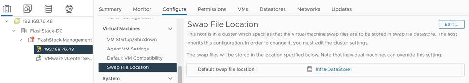
Step 25. Select the new host, right-click and select Settings.
Step 26. Select in the left menu of the center pane Virtual Machines - Swap File Location. Click Edit.
Step 27. Select Infra-DataStore1 and click OK.
Step 28. Select System - Time Configuration in the left menu of the center pane.
Step 29. Select the Network Time Protocol service and click Edit. Confirm the NTP servers and click OK.
Step 30. Select Hardware - Overview.
Step 31. Scroll down the right pane and confirm the power management active policy is set to high performance.
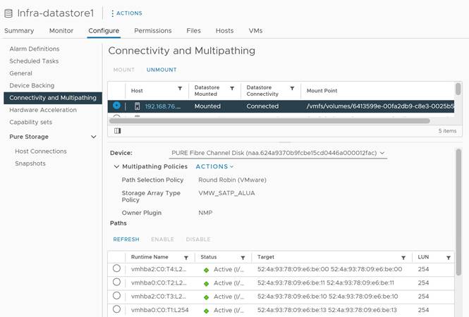
It is important to verify proper connectivity prior to implementing production workload on a host or volume.
Step 32. Navigate to Inventory > Storage.
Step 33. Click the infra-datastore1 and select Configure - Connectivity and Multipathing.
Step 34. Select the mounted volume to verify the proper numbers of paths, I/O balance, and redundancy on the FlashArray.
FlashStack VMware vSphere Distributed Switch (vDS)
This section provides detailed procedures for installing the VMware vDS in vCenter and on the first FlashStack ESXi Management Host.
In the Cisco UCS setup section of this document, two sets of vNICs were setup. The vmnic ports associated with the vDS0-A and B vNICs will be placed on the VMware vDS in this procedure. The vMotion VMkernel port(s) will be placed on the vDS.
A vMotion, and a VM-Traffic port group will be added to the vDS. Any additional VLAN-based port groups added to the vDS would need to have the corresponding VLANs added to the Cisco UCS LAN cloud, to the Cisco UCS vDS0-A and B vNIC templates, and to the Cisco Nexus 9K switches and vPC peer-link interfaces on the switches.
In this document, the infrastructure ESXi management VMkernel ports, the In-Band management interfaces including the vCenter management interface are left on vSwitch0 to facilitate bringing the virtual environment back up in the event it needs to be completely shut down. The vMotion VMkernel ports are moved to the vDS to allow QoS marking of vMotion to be done at the VLAN level in the vDS if vMotion needs to have QoS policies applied in the future. The vMotion port group is also pinned to Cisco UCS fabric B. Pinning should be done in a vDS to ensure consistency across all ESXi hosts.
Procedure 1. Configure the VMware virtual distributed switch (vDS)
Step 1. Navigate to https://<vCenter FQDN> and select Launch vSphere Client (HTML5).
Step 2. Login to the VMware vSphere client using the SSO (administrator@vsphere.local) user credentials.
Step 3. Navigate to Inventory > Networks.
Step 4. Right-click the FlashStack-DC datacenter and select Distributed Switch - New Distributed Switch from the menu.
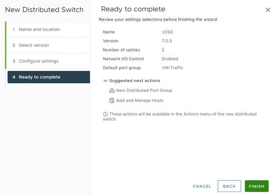
Step 5. Give the distributed switch a descriptive name (vDS0) and click Next.
Step 6. Select version 7.0.3 - ESXi 7.0.3 and later. Click Next.
Step 7. Change the number of uplinks to 2. If VMware Network I/O control is to be used for Quality of Service, leave Network I/O control enabled. Otherwise, disable Network I/O control. Change the port group name to VM-Traffic and click Next.
Step 8. Review the information and click Finish to complete creating the vDS0.
Step 9. Expand the FlashStack-DC datacenter and the newly created vDS0 and select the vDS.
Step 10. Right-click the VM-Traffic port group and select Edit Settings from the menu.
Step 11. Click VLAN in the new window.
Step 12. Select VLAN type VLAN and provide the VLAN ID. Click OK.

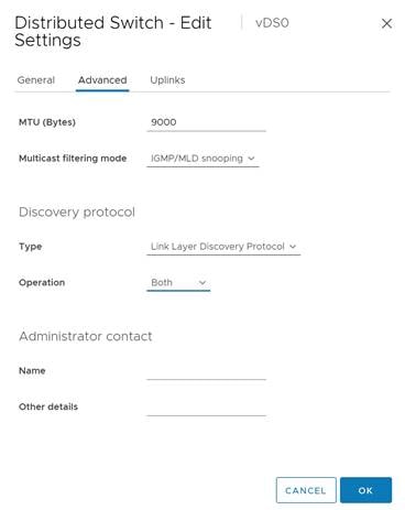
Step 13. Right-click vDS0 and select Settings - Edit Settings from the menu.
Step 14. In the Advanced tab, change the MTU size to 9000. Optionally change the discovery protocol to Link Layer Discovery Protocol and the operation mode to both. Click OK.
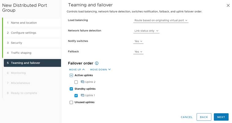
Step 15. Right-click the vDS0, select Distributed Port Group - New Distributed Port Group from the menu.
Step 16. Provide VMkernel-vMotion as port group name and click Next.
Step 17. Select VLAN type VLAN and provide the VLAN ID. Select the check box Customize default policies configuration and click Next.
Step 18. Keep the security options on Reject and click Next.
Step 19. Keep the Ingress and Egress traffic shaping options disabled and click Next.
Step 20. Select Uplink 1 from the list of active uplinks and click the mode down tab twice to move Uplink 1 from the active uplinks to the standby uplinks list. Then click Next.
Step 21. Keep NetFlow disabled and click Next.
Step 22. Keep Block All Ports on No and click Next.
Step 23. Review and confirm the options. Click Finish to create the port group.
Step 24. Right-click the vDS0 and select Add and Manage Hosts.
Step 25. Select Add hosts and click Next.
Step 26. Select the check box to add the ESXi host. Click Next.
Step 27. Select Uplink 1 from the assign uplink drop-down list in the row for vmnic2 and select Uplink 2 for vmnic3. If more than one host is being connected to the vDS, use the apply this uplink assignment to the rest of the hosts check box. Click Next.
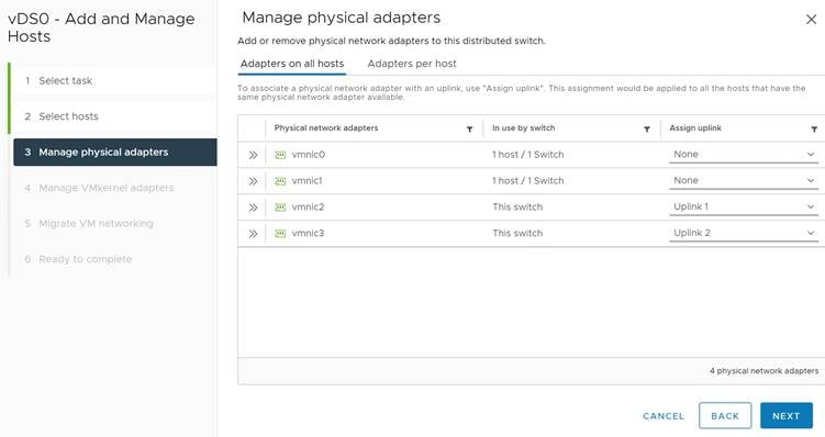
Step 28. No changes on the manage VMkernel adapters screen. Click Next.
Step 29. Do not migrate any VM networking ports. Click Next.
Step 30. Review and click Finish to compete the add host wizard.
To build an SAP HANA ready vSphere cluster, dedicated networks are required for SAP application, user traffic, admin, and management, as well as for NFS. Follow the SAP HANA network requirements white paper to decide how many networks have to be added to support a specific SAP HANA workload in a VM and ultimately on the host.
Follow steps 13 to 28 to add the required SAP HANA networks. It is a best practice to alternate the active and standby uplink during the setup, use Table 5 for as guidance.
Table 5. Active and Standby Uplink distribution for SAP HANA VLANs
| VLAN ID |
|
|
MTU |
Active uplink |
Standby uplink |
| 223 |
AppServer |
SAP Application Server VLAN |
1500 |
1 |
2 |
| 221 |
HANA-Backup |
SAP HANA Backup VLAN |
9000 |
2 |
1 |
| 222 |
HANA-Client |
SAP HANA Client VLAN |
9000 |
1 |
2 |
| 224 |
HANA-DataSource |
SAP HANA DataSource VLAN |
9000 |
2 |
1 |
| 225 |
HANA-Replication |
SAP HANA Replication VLAN |
9000 |
1 |
2 |
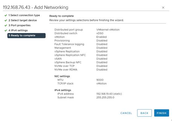
Procedure 2. Add the vMotion VMkernel port to the ESXi host(s) on the VMware vDS
Step 1. Navigate to Inventory > Hosts and Clusters and select the ESXi host.
Step 2. Select the Configure tab.
Step 3. Select Networking - VMkernel adapters and click Add Networking.
Step 4. Select VMkernel Network Adapter and click Next.
Step 5. Browse the existing network and select the VMkernel-vMotion network. Click Ok.
Step 6. Click Next and confirm the network label is VMkernel-vMotion(vDS0).
Step 7. Select the vMotion TCP/IP stack and click Next.
Step 8. Select Use static IPv4 settings and provide the host’s vMotion IPv4 address and subnet. Click Next.
Step 9. Review the information and click Finish to add the vMotion VMkernel port.
Configure vSphere Cluster Services
The vSphere Cluster Services (vCLS) is a new feature introduced with vSphere 7 U1. It ensures cluster services such as vSphere DRS and vSphere HA are available to maintain the resources and health of the workloads like SAP HANA running in the cluster independent of the vCenter Server instance availability.
The vSphere Clustering service uses agent VMs to maintain cluster services health and up to three VMs are created when adding hosts to the cluster.
vSphere Clustering Service deployment guidelines for SAP HANA landscapes
As of SAP Notes 2937606, SAP HANA production VMs should not get co-deployed with any other workload VMs on the same vSphere ESXi host and NUMA node sharing between SAP HANA and non-HANA is not allowed. Because of these guidelines and due to the mandatory and automated installation process of vSphere Clustering Service it is required to ensure vCLS VMs will get migrated to hosts that do not run SAP HANA production-level VMs.
This can be achieved by configuring a vSphere Clustering Service VM anti-affinity policy. This policy describes a relationship between VMs that have been assigned a special anti-affinity tag (for example a tag named SAP HANA) and vSphere Clustering service system VMs.
If this tag is assigned to SAP HANA VMs, the policy discourages placement of vSphere Clustering Service VMs and SAP HANA VMs on the same host. This assures that vSphere Clustering Service VMs and SAP HANA VMs do not get co-deployed.
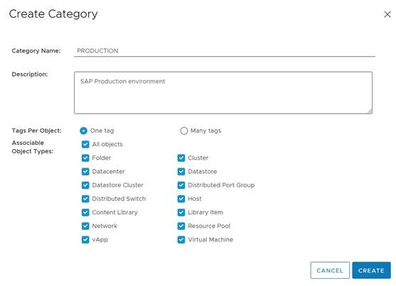
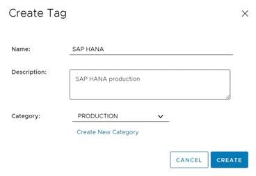
Procedure 1. Create Category and Tag
Step 1. In the vSphere client menu select Tags & Custom Attributes.
Step 2. In the TAGS screen click New.
Step 3. Create a new category (PRODUCTION) and enter a category description. Click Create.
Step 4. Select the category. Enter a tag name (SAP HANA) and a description. Click Create.
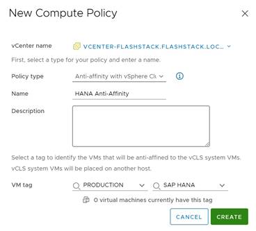
Procedure 2. Create Anti-Affinity policy for vCLS
Step 1. In the vSphere client menu select Policies and Profiles.
Step 2. Select Compute Policies and click Add.
Step 3. Select the policy type Anti-affinity with vSphere Cluster Service from the drop-down list.
Step 4. Enter a policy name and policy description.
Step 5. Select the category Production and tag SAP HANA from the drop-down lists and click Create.
Enable EVC on the VMware cluster
In cluster environments with mixed compute nodes and CPU architectures it is required to ensure CPU compatibility when planning to move VMs between hosts of different architectures. In addition, special attention requires the number of sockets, cores and main memory which must be adapted manually if required. Other cluster features such as vSphere DRS and vSphere HA are fully compatible with EVC.
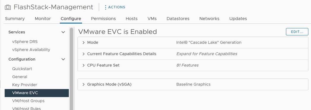
Procedure 1. Enable EVC for Intel Hosts
Step 1. Navigate to Inventory > Hosts and Clusters and select the cluster object (FlashStack-Management).
Step 2. Click the Configure tab, select Configuration - VMware EVC. Then click Edit.
Step 3. Select Enable EVC for Intel Hosts.
Step 4. Select CPU mode Intel “Cascade Lake” generation.
Step 5. Review the Compatibility box displays “Validation succeeded. Then click Ok.
Add and configure additional VMware ESXi hosts in vCenter
This section details the steps to add and configure an ESXi host in vCenter. This section assumes the host has had VMware ESXi 7.0 U3 installed, the management IP address set, the nfnic driver updated and the Cisco UCS Tool installed. This procedure is being run on any additional ESXi management host, but at least on two additional hosts.
Procedure 1. Add a VMware ESXi host to VMware vCenter
Step 1. Navigate to Inventory > Hosts and Clusters and right-click the cluster object (FlashStack-Management).
Step 2. Select Add Hosts and enter the IP address (or FQDN), the username (root) and password.
Step 3. To add multiple hosts at the same time click Add Host and provide the other host information. Click Next.
Step 4. Select the check box(es) to confirm the security alert. Click Ok and Next.
Step 5. Review the summary and click Finish to add the host(s).
The new hosts are placed into maintenance mode and show warnings that the ESXi shell and SSH are enabled. These warning can be suppressed.
Step 6. Navigate to Inventory > Hosts and Clusters and select the new ESXi host.
Step 7. Click the Configure tab and select System - Time Configuration.
Step 8. Select the Network Time Protocol service and click Start.
Step 9. Select Virtual Machines - Swap File Location and click Edit.
Step 10. Use the Infra-Datastore1 as swap file location. Click Ok.
Step 11. Select Hardware - Overview and scroll down to confirm the power management active policy is set to high performance.
Step 12. Confirm all configured FC paths are up. Select Storage - Storage Devices.
Step 13. Select the FlashArray//X FC disk with LUN ID 1 hosting the ESXi installation.
Step 14. In the path tab, ensure all configured FC paths appear with status active (I/O).
Step 15. Confirm the virtual switch configuration. Select networking - virtual switches and click Edit.
Step 16. Change the MTU size to 9000.
Step 17. Select Teaming and failover. Click on the vmnic1 adapter and move it using the arrows to the active adapter group. Click Ok.
Step 18. Click the dot menu to the right of VM Network. Click Edit Settings.
Step 19. Rename the port group to IB-MGMT Network and keep the VLAN ID set to None (0). Click Next.
Step 20. Review the information and click Finish.
Step 21. Click Add Networking to add a new VM port group.
Step 22. Select Virtual Machine Port Group for a Standard Switch and click Next.
Step 23. Confirm vSwitch0 is selected as existing standard switch and click Next.
Step 24. Name the port group OOB-MGMT Network and change the VLAN ID set to <OOB-MGMT-VLAN-ID>. Click Next.
Step 25. Review the information and click Finish.
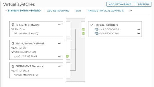
Step 26. Select Networking - VMkernel adapters and click Add networking.
Step 27. Select VMkernel Network Adapter and click Next.
Step 28. Browse the existing network and select the VMkernel-vMotion network. Click Ok.
Step 29. Click Next and confirm the network label is VMkernel-vMotion(vDS0). Select the vMotion TCP/IP stack and click Next.
Step 30. Select Use static IPv4 settings and provide the host’s vMotion IPv4 address and subnet. Click Next.
Step 31. Review the information and click Finish to add the vMotion VMkernel
Step 32. Repeat steps 1 to 34 for all new hosts being added.
Step 33. Right-click each ESXi host and select Maintenance Mode - Exit Maintenance Mode.
If the Cisco UCS servers have Trusted Platform Module (TPM) 2.0 modules installed, the TPM can provide assurance that ESXi has booted with UEFI Secure Boot enabled and using only digitally signed code. In the Cisco Intersight policies, UEFI secure boot was enabled in the boot order policy. A server can boot in UEFI secure boot mode with or without a TPM 2.0 module installed. If it has a TPM, VMware vCenter can attest that the server booted with UEFI Secure Boot.
Procedure 1. Verify TPM attestation status.
Step 1. In the vCenter HTML5 vSphere client, select the cluster FlashStack-Management in the hosts and clusters section.
Step 2. Select Monitor in the center pane and scroll down the menu in the center pane.
Step 3. Select Security from the menu. The Attestation status will show the status of the TPM. If no TPM module is installed, the status will display N/A.
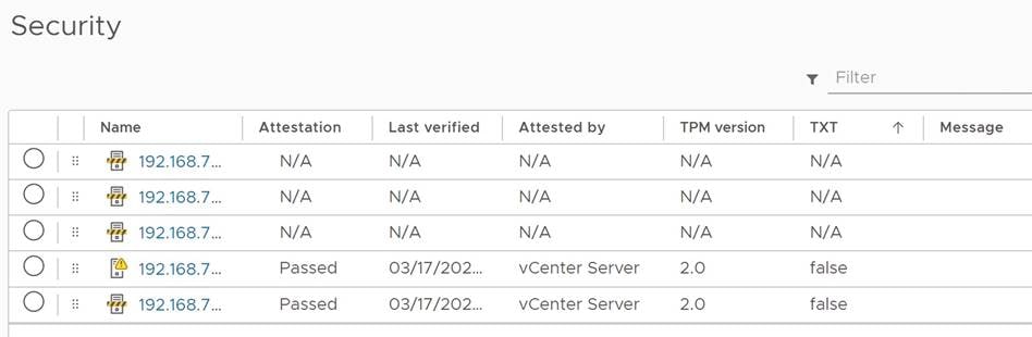
Step 4. If the TPM attestation does not pass after the host is added, it is required to disconnect and reconnect the host from vCenter.
Procedure 2. Avoiding Boot failure when UEFI secure booted server profiles are moved.
Hosts in the FlashStack for SAP HANA data center are configured for SAN boot. While Cisco supports stateless compute where a server profile can be moved from one blade or compute node to another seamlessly, the ESXi host runs into PSOD and ESXi will fail to boot if the following conditions are met:
● TPM module is present in the node.
● VMware vSphere 7.0 U2 or later.
● Boot mode is UEFI secure boot.
The PSOD error message is: Unable to restore system configuration. A security violation was detected. https://via.vmw.com/security-violation.
The TPM seals the sensitive information by using a TPM policy based on PCR values for UEFI Boot. This value is loaded during subsequent reboots if the policy is satisfied as true which causes the issue.
Procedure 3. Gather the recovery keys from all hosts
The recommendation is to gather the recovery keys from all hosts once the ESXi setup is complete.
Step 1. Open the ESXi host SSH terminal.
Step 2. Gather the recovery key using the following command:
$ esxcli system settings encryption recovery list
Recovery ID Key
-------------------------------------- ---
{B5898133-F823-42F3-9E07-9C96631B60DD} 157641-123201-253827-393198-391835-105572-
460224-096345-043161-467608-394426-707718-
640993-283021-136183-138989
Step 3. Store the recovery ID and key from all hosts in a safe location.
Step 4. After associating the server profile to the new compute node or blade, stop the ESXi boot sequence by pressing Shift + O when you see the ESXi boot screen in the vKVM console.
Step 5. Add the recovery key using the following boot option: encryptionRecoveryKey=<recovery_key>.
Step 6. Press Enter to continue the boot process.
Step 7. Persist the change on for the ESXi host using the following command:
$ /sbin/auto-backup.sh
Saving current state in /bootbank
Creating ConfigStore Backup
Locking esx.conf
Creating archive
Unlocked esx.conf
Using key ID
5201b01e-3e26-a708-0e66-ede01489c16a to encrypt
Clock updated.
For more detailed information refer to Recover the Secure ESXi configuration.
Cisco Intersight Hardware Compatibility List (HCL) status
Cisco Intersight evaluates the compatibility of customer’s Cisco Unified Computing System to check if the hardware and software have been tested and validated by Cisco or Cisco partners. Intersight reports validation issues after checking the compatibility of the server model, processor, firmware, adapters, operating system, and drivers, and displays the compliance status with the Hardware Compatibility List (HCL).
To determine HCL compatibility for VMware ESXi, Cisco Intersight uses Cisco UCS Tools. The Cisco UCS Tools is part of VMware ESXi Cisco custom ISO, and no additional configuration is required.
For more information about Cisco UCS Tools manual deployment and troubleshooting, go to: https://intersight.com/help/saas/resources/cisco_ucs_tools#about_cisco_ucs_tools.
Procedure 1. Retrieve detailed information about the hardware compatibility of a compute node
Step 1. Open Cisco Intersight in a web browser at https://intersight.com and log into your Intersight account.
Step 2. From the Service Selector, select Infrastructure Service.
Step 3. From the left navigation pane, select Operate - Servers.
Step 4. Select the server of your choice and click the HCL tab in the center pane to review the HCL validation status.
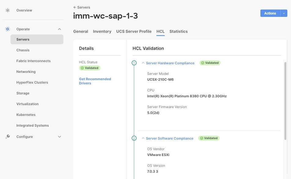
Pure Storage vSphere Client Plugin
The Pure Storage Plugin for the vSphere Client provides the ability to VMware users to have insight into and control of their Pure Storage FlashArray environment while directly logged into the vSphere Client. The Pure Storage plugin extends the vSphere Client interface to include environmental statistics and objects that underpin the VMware objects in use and to provision new resources as needed. Additional information is available in the user guide of the Pure Storage Plugin here: https://support.purestorage.com/Solutions/VMware_Platform_Guide/User_Guides_for_VMware_Solutions/Using_the_Pure_Storage_Plugin_for_the_vSphere_Client.
The Pure Storage vSphere Client Plugin will be accessible through the vSphere Client after deployment of the Pure Storage VMware appliance.
Procedure 1. Access the Pure Storage vSphere Client Plugin
Step 1. The Pure VMware appliance is an OVA that can be deployed from Pure at the link provided in the user guide here: https://support.purestorage.com/Solutions/VMware_Platform_Guide/User_Guides_for_VMware_Solutions/Using_the_Pure_Storage_Plugin_for_the_vSphere_Client/vSphere_Plugin_User_Guide%3A_Installing_the_Remote_vSphere_Plugin_with_the_Pure_Storage_VMware_Appliance. It is required to download the OVA for both, the online and offline deployment.
Step 2. Follow the user guide opened in step 1.
Step 3. Once the Pure Storage VMware appliance is deployed, connect it to your vCenter:
◦ Open an SSH connection to the appliance using the OVA VM’s DNS name or IP address displayed in vCenter.
◦ In the SSH shell login with the pureuser account. On the first login the password needs to be changed.
◦ Login again with the new password for the pureuser account.
◦ Once the appliance has been deployed and configured, then the vSphere Remote Plugin can be configured.
◦ Use the pureplugin register command and positional arguments to register the remote plugin’s extension with the vCenter server.
pureplugin register --host <IP or FQDN of vCenter> --user <vSphere account>
Step 4. A successful registration will appear within vCenter soon after.
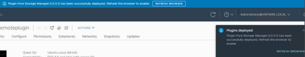
Step 5. Generate JWT for your Pure1 account. For more information visit: https://support.purestorage.com/Pure1/Pure1_Manage/Pure1_Manage_-_REST_API/Pure1_Manage_-_REST_API__Reference.
Step 6. In the vCenter vSphere Client interface select Pure Storage from the top left menu button.
Step 7. Click Authenticate with Pure1.
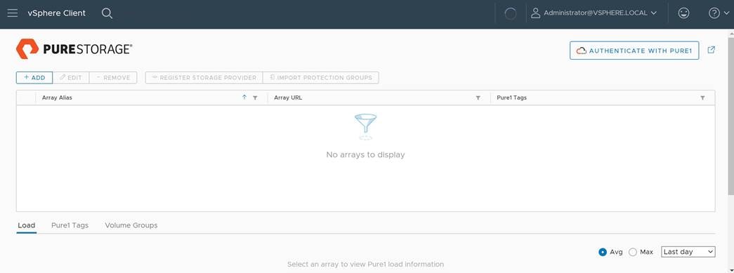
Step 8. Click Add to add a single FlashArray//X and provide the array name, the array URL and user credentials.
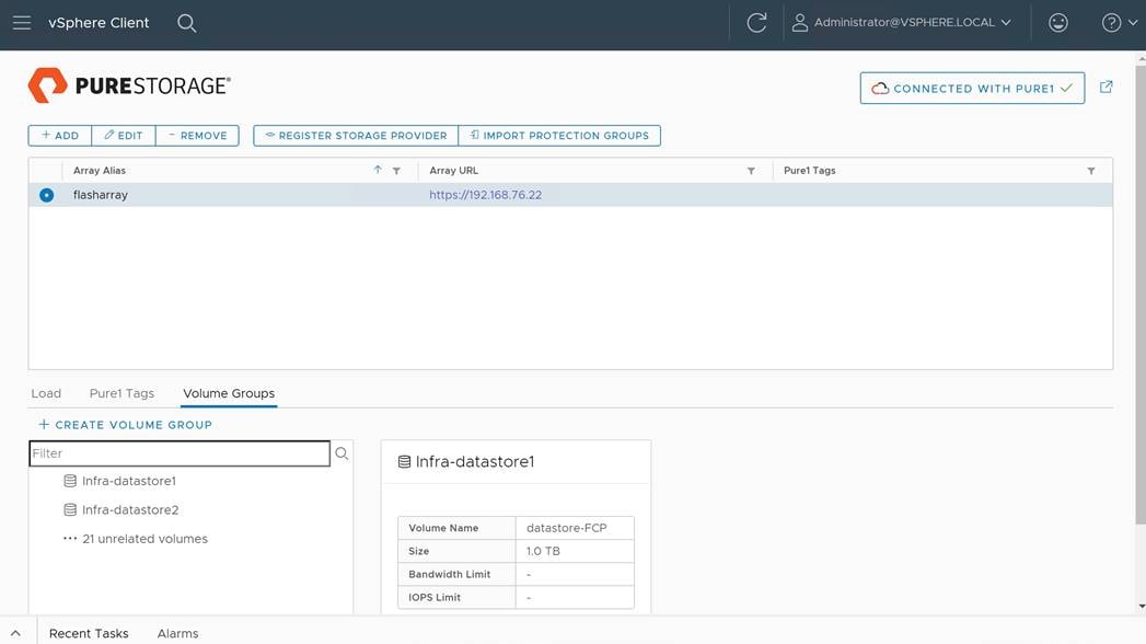
Step 9. Select the newly added array and click Register storage providers.
Step 10. Enter the username (vvol-admin) and password and click Register.
Step 11. Once the Storage Provider is successfully registered, navigate to the vCenter Inventory page (vcenter-flashstack).
Step 12. Select the Configure tab in the center pane and select menu entry Security - Storage Providers.
Step 13. Confirm the storage providers are online and healthy.
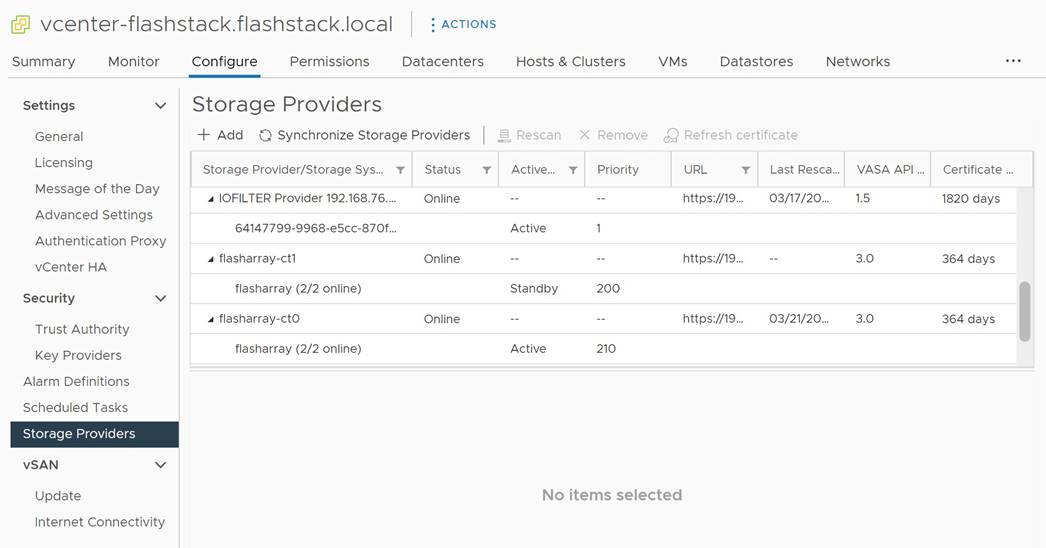
Procedure 2. Create VMFS datastore using Pure vSphere Plugin
VMware vSphere datastores can be of different types, such as VMFS, NFS or vSphere Virtual Volumes (vVol) based datastores. All these datastore types are fully supported with SAP HANA deployments.
To create a VMFS datastore using the Pure vSphere Plugin, follow these steps. Alternatively, you can create a vVol datastore using the same wizard, but this is not explained in this deployment guide.
Step 1. Login to the VMware vSphere client using the SSO (administrator@vsphere.local) user credentials.
Step 2. Navigate to Inventory > Hosts and Clusters.
Step 3. Right-click the cluster object (FlashStack-Management) and select Pure Storage - Create Datastore.
Step 4. Keep the type VMFS selected and click Next.
Step 5. Keep the version VMFS 6 selected and click Next.
Step 6. Enter a datastore name (infra-datastore03) and datastore size (ex. 200 GB) and click Next.
Step 7. Select the cluster under Compute Resource (FlashStack-Management) and click Next.
Step 8. Select the registered FlashArray//X (flasharray) and click Next.
Step 9. (Optional) Add the new datastore to the protection group created before. Click Next.
Step 10. Do not change the settings on the Volume Group & QoS page. Click Next.
Step 11. Review the information and click Finish to create the datastore.
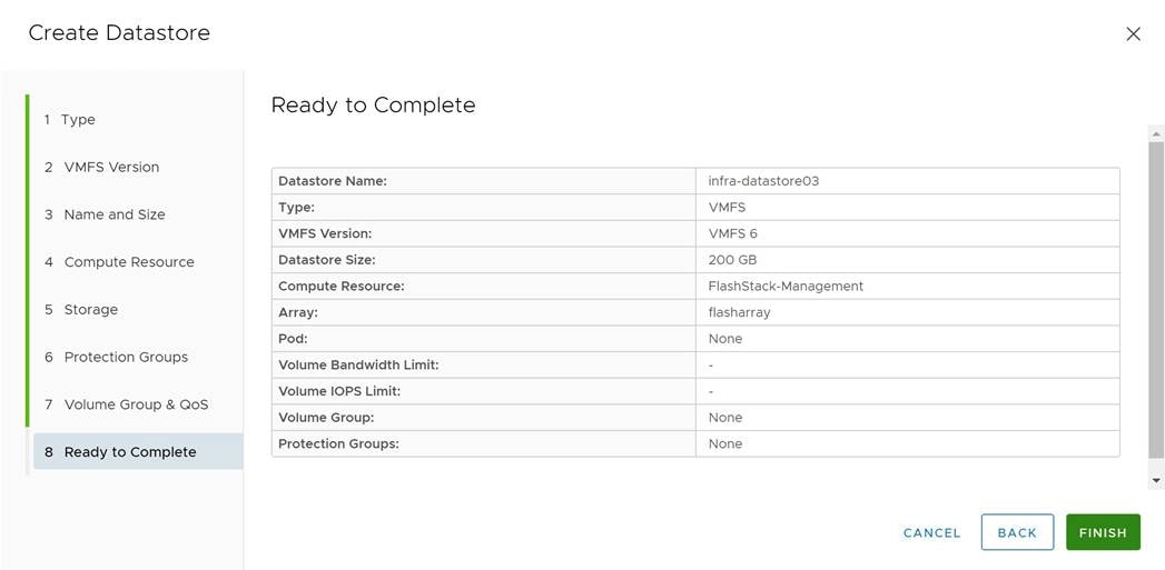
Cisco Intersight Cloud Orchestration
This chapter contains the following:
● Fibre Channel host registration using Cisco Intersight
Cisco Intersight Cloud Orchestrator simplifies orchestration and automation for infrastructure and workloads across hybrid cloud by providing an easy-to-use workflow designer. Based on a library of curated, multi-domain tasks (custom or provided by Cisco), it enables users to create workflows, quickly and easily, without being coding experts! This enables quick and easy automation and deployment of any infrastructure resource, from servers, to VMs and the network, taking away some of the complexity of operating your hybrid IT environment.
Fibre Channel host registration using Cisco Intersight
Procedure 1. Register the FC host using Cisco Intersight
Step 1. Open Cisco Intersight in a web browser at https://intersight.com and log into your Intersight account.
Step 2. From the Service Selector, select Cloud Orchestrator.
Step 3. From the left navigation pane, select workflows - all workflows.
Step 4. Select New Storage Host from the workflow list.
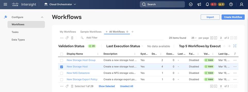
Step 5. Click Execute.
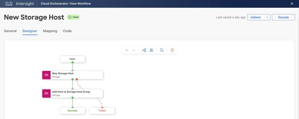
Step 6. Select the appropriate organization (default).
Step 7. Click Select Storage Device and select the appropriate Pure Storage device.
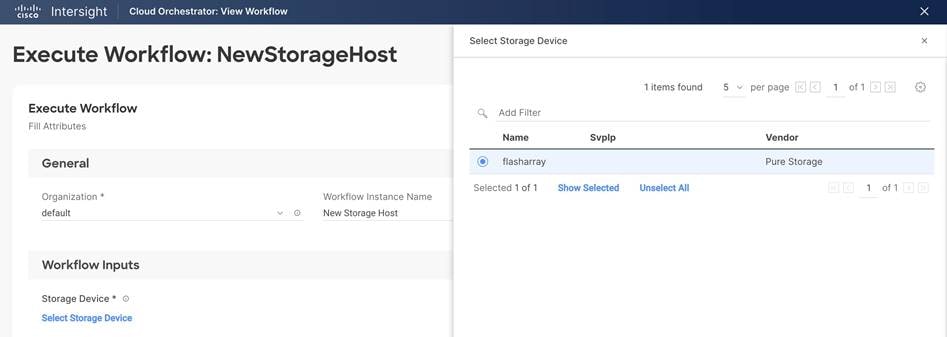
Step 8. (Optional) Click Select Host Group and select the host group.
Step 9. Enter the host name and WWNs for the host VM-Host-Infra-FCP-06.
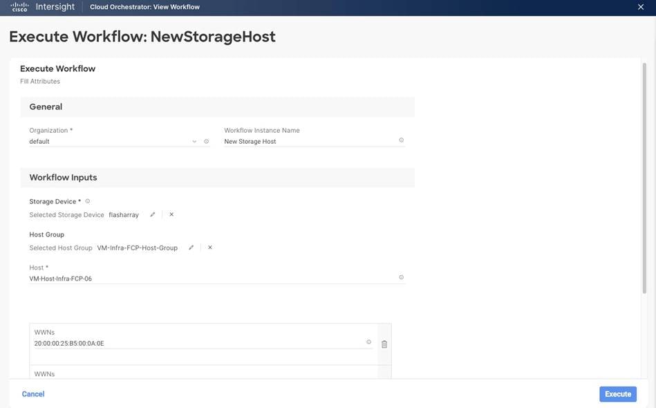
Step 10. Click Execute the run the workflow.
Step 11. The workflow is being displayed. Confirm the execution was successful.
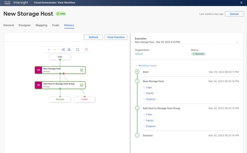
Procedure 2. Create VMFS datastore using Cisco Intersight
vSphere datastores can be of different types, such as VMFS, NFS or vSphere Virtual Volumes (vVol) based datastores. All these datastore types are fully supported with SAP HANA deployments.
To create a VMFS datastore, follow these steps. Alternatively, you can create a vVol datastore using the same wizard.
Step 1. Open Cisco Intersight in a web browser at https://intersight.com and log into your Intersight account.
Step 2. From the Service Selector, select Cloud Orchestrator.
Step 3. From the left navigation pane, select workflows - all workflows.
Step 4. Select New VMFS Datastore from the workflow list.
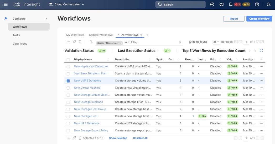
Step 5. Click Execute.
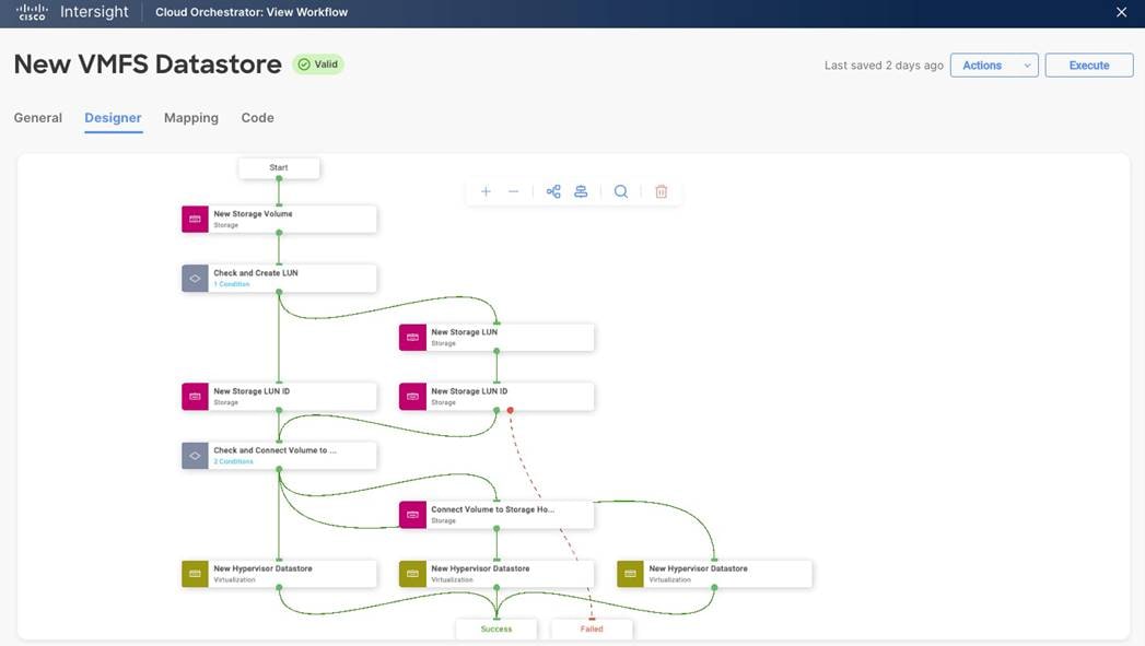
Step 6. Select the appropriate organization (default).
Step 7. Provide a Workflow Instance Name (Create infra-datastore04 VMFS datastore).
Step 8. Select the storage device (flasharray) and click Select.
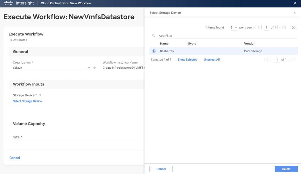
Step 9. (Optional) Select a Storage Host Group and click Select.
Step 10. Keep the LUN number empty and have the FlashArray select the next available LUN number. The LUN ID numbering deviates from Purity//FA. Purity will assign the next available LUN ID counting down from 254 while the workflow designer counts upwards from 1.
Step 11. Provide a volume name (datastore-FCP-infra04).
Step 12. Provide the volume size (200).
Step 13. Provide the volume capacity unit (GiB).
Step 14. Select the storage host to assign the VMFS datastore to and click Select.
Step 15. Select the hypervisor manager (vCenter) and click Select.
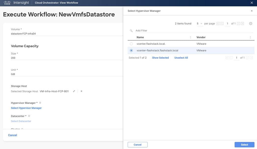
Step 16. Select the datacenter (FlashStack-DC) and click Select.
Step 17. Select cluster (FlashStack-Management) and click Select.
Step 18. Select the host IP address and click Select.
Step 19. Provide a datastore name (infra-datastore04).
Step 20. Provide the datastore type (VMFS-6).
Step 21. Review the settings and click Execute.
Step 22. The execution workflow will be displayed in the History tab of the workflow.
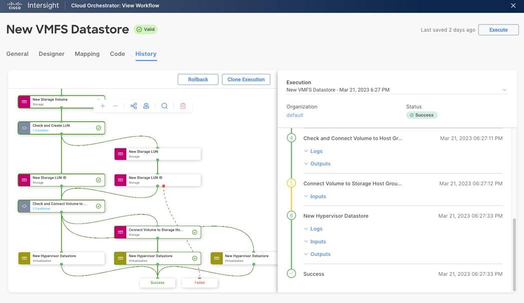
SAP HANA on VMware vSphere
This chapter contains the following:
● Overview
● Deployment options and sizes
● SAP HANA on vSphere configuration and sizing guidelines
● SAP HANA virtual machine configuration
The FlashStack architecture provides a starting point for a VMware virtualized SAP HANA project.
Virtualized SAP HANA (vHANA) systems can get as big as 448 vCPUs with up to 12 TB RAM per VM; which is the maximum validated configuration and requires an 8-socket host system like the Cisco C890 M5 rack server. Also, the maximum number of vCPUs available for a VM may be limited by the expected use case, such as extremely network heavy OLTP workloads with thousands of concurrent users.
SAP HANA can get deployed on supported vSphere versions and validated CPU generations as scale-up and scale-out deployments as a single VM per server or multiple SAP HANA systems on a single physical host. Only 2-, 4- and 8-CPU socket VMware and SAP supported and certified systems can get used for SAP HANA production-level systems.
It is supported to run SAP HANA VMs next to non-SAP HANA VMs, such as vSphere management VMs or SAP application servers, when these VMs run on different CPU sockets, or when an SAP HANA and SAP NetWeaver Application Server (AS) run in one virtual machine.
Larger SAP HANA systems can get deployed as scale-out configuration. In a scale-out configuration, up to 16 nodes work together to provide larger memory configurations. As of today, the maximum supported scale-out configurations for SAP BW environments are 16 x 4-CPU wide VMs with 2 TB RAM per node with SAP HANA CPU sizing class L configuration, and up to 8 x 4-CPU wide VMs with up to 3 TB RAM per node and SAP HANA CPU sizing class M configurations. 8-socket wide SAP HANA VMs for scale-out deployments are yet not SAP HANA supported but can be implemented with SAP HANA running bare-metal installed without hypervisor.
Besides SAP HANA, most SAP applications and databases can get virtualized and are fully supported for production workloads either on dedicated vSphere hosts or running consolidated side by side.
Table 6. Overview of SAP HANA on vSphere deployment options
| Host socket size |
Certified configuration |
Virtual SAP HANA VM sizes |
| 2-socket |
Cisco UCS M5 Cascade Lake <= 3 TiB, max. 112 threads Cisco UCS M6 Ice Lake <= 4 TiB, max. 160 CPU threads |
Scale-Up: 0.5, 1 and 2-socket wide VMs Scale-Out: N/A Min: 8 vCPUs and 128 GiB vRAM Max: 112 vCPUs and 3 TiB vRAM Max: 160 vCPUs and 4 TiB vRAM Up to 4 VMs per 2-socket host |
| 4-socket |
Cisco UCS M5 Cascade Lake <= 6 TiB, max. 224 threads |
Scale-Up: 0.5, 1, 2, 3 and 4-socket wide VMs Scale-Out: 4-socket wide VMs with 224 vCPUs Min: 8 vCPUs and 128 GiB vRAM Max: 224 vCPUs and 6 TiB vRAM Up to 8 VMs per 4-socket host |
The supported SAP HANA start release is SAP HANA 1.0 SPS 12 Revision 122.19; SAP HANA 2.0 is recommended. Ensure to review SAP Note 2937606 - SAP HANA on VMware vSphere 7.0 in production for the most current updates.
Special attention is required if the vSphere cluster consists of hosts with a different number of sockets and different CPUs or CPU architectures. A full-socket CPU configuration on the Cisco UCS M6 X210c with Intel Xeon Platinum 8380 processor uses 40 cores, while a full-socket configuration on the Cisco UCS M5 B480 blade server with Intel Xeon Platinum 8276L processor uses 28 cores only. The recommendation is to keep the SAP HANA VMs on the same server model to avoid virtual machine reconfigurations to not overcommit CPU resources.
SAP HANA on VMware vSphere configuration and sizing guidelines
SAP HANA must be sized according to the existing SAP HANA sizing guidelines and VMware recommendations. The sizing report provides information about the required CPU size (SAP Application Performance Standard (SAPS)), memory and storage resources.
The general sizing recommendation is to scale-up first; for production environments CPU and memory over-commitment must be avoided. Depending on workload-based sizing results (SAP Note 2779240 - Workload-based sizing for virtualized environments) a deviation from the existing core-to-memory ratio might be possible for vHANA.
VMware vSphere uses datastores to store virtual disks. Datastores provide an abstraction of the storage layer that hides the physical attributes of the storage devices from the virtual machines. The datastores types applicable for FlashStack, such as VMFS or vSphere virtual volumes (vVOL) are fully supported with SAP HANA deployments.
A single FlashArray volume can offer the full performance of an entire FlashArray and there is no immediate performance benefit to use more than one volume for the virtual machines. It is best practice to create a dedicated volume for each virtual machine having one VMFS datastore which stores multiple VMware virtual machine disks (VMDKs).
All SAP HANA instances do have an operating system, local SAP, database log, database data, and shared SAP volume. The storage sizing calculation of these volumes is based on the overall amount of memory needed by SAP HANA’s in-memory database.
This sizing calculation for a virtualized SAP HANA with 1.5 TB RAM is as follows:
● VMDK OS >= 50 GB (recommended 120 GB thin provisioned)
● VMDK SAP >= 60 GB (recommended 100 GB thin provisioned)
● VMDK Shared = 1,024 GB (thick provisioned)
● VMDK Log = 512 GB (thick provisioned)
● VMDK Data = 1856 GB (thick provisioned)
● VMDK Backup >= 2048 GB (thin provisioned) (optional)
For this example, the total VM storage capacity requirement is 3.5 TB / with optional backup 5.5 TB.
To determine the cluster-wide storage capacity requirements, this calculation needs to get done for all possible running SAP HANA VMs in a vSphere cluster. All SAP HANA production VMs must fulfill the capacity as well as the throughput and latency requirements as specified by SAP Note 1943937 and SAP Note 2493172.
The FlashArray//X20 R3 can serve up to 22 SAP HANA nodes and the total number of SAP HANA nodes scale with the size of the FlashArray//X to up to 44 SAP HANA nodes with a FlashArray//X90 R3.
Selecting the correct components and configuration is vital and the only way to achieve the performance and reliability requirements for SAP HANA.
SAP HANA virtual machine configuration
With the vHANA example requirements above (full-socket CPU, 1.5 TB RAM) the deployment procedure of a single SAP HANA instance can be executed as follows on a Cisco UCS M5 B480 Blade Server:
Procedure 1. Create VMFS datastore using Pure vSphere Plugin.
Create a VMFS datastore using the Pure vSphere Plugin. This procedure adds the volume to the VM-Infra-FCP-Host-Group on the FlashArray//X.
Step 1. Login to the VMware vSphere client using the SSO (administrator@vsphere.local) user credentials.
Step 2. Navigate to Inventory > Hosts and Clusters.
Step 3. Right-click the cluster object (FlashStack-Management) and select Pure Storage - Create Datastore.
Step 4. Keep the type VMFS selected and click Next.
Step 5. Keep the VMFS 6 version selected and click Next.
Step 6. Enter a datastore name (vhana01-datastore) and datastore size (7680 GB) and click Next.
Step 7. Select the cluster under Compute Resource (FlashStack-Management) and click Next.
Step 8. Select the registered FlashArray//X (flasharray) and click Next.
Step 9. Skip the protection group page and click Next.
Step 10. Do not change the settings on the Volume Group & QoS page. Click Next.
Step 11. Review the information and click Finish to create the datastore.
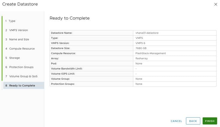
Procedure 2. Create an SAP HANA virtual machine
The new vHANA instance will use the VMFS datastore previously created, which will keep the VMDKs for the OS and SAP binaries, as well as SAP HANA data, log and shared.
Step 1. Navigate to Inventory > Hosts and Clusters.
Step 2. Right-click the cluster object (FlashStack-Management) and select New Virtual Machine.
Step 3. Select the creation type Create a new virtual machine and click Next.
Step 4. Enter a virtual machine name (vHANA01) and click Next.
Step 5. Select the compute resource to run the VM. Expand the cluster object and select the ESXi host. Click Next.
Step 6. Select the new datastore (vhana01-datastore) and click Next.
Step 7. Keep the ESXi 7.0 U2 and later compatibility and click Next.
Step 8. Select Linux as Guest OS Family and either the Guest OS version Red Hat Enterprise Linux 8 or SUSE Linux Enterprise 15. Click Next.
Step 9. Enter 56 vCPUs from the drop-down list.
Step 10. Expand the CPU entry and select 28 cores which changes the number of sockets to two. CPU Hot Plug stays disabled.
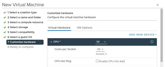
Step 11. Enter 1536 GB memory. Expand the field and checkmark Reserve all guest memory (all locked).
Step 12. In the new hard disk field, enter 120 GB. Expand the field and change disk provisioning to thin provision.
Step 13. From the location drop-down list, select browse to change the location to vhana01-datastore.
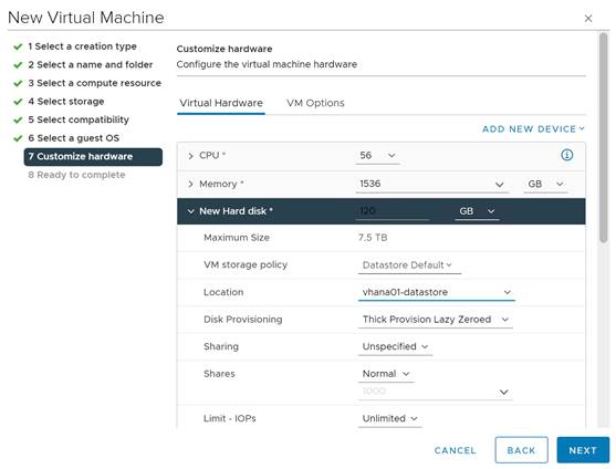
Step 14. Click Add New Device and from the drop-down list Disks, Drives and Storage - Hard Disk.
Step 15. In the new hard disk field, enter 100 GB. Expand the field and change disk provisioning to thin provision.
Step 16. From the location drop-down list, select browse to change the location to vhana01-datastore.
Step 17. Click Add New Device and from the drop-down list Disks, Drives and Storage - Hard Disk.
Step 18. In the new hard disk field, enter 1024 GB. Expand the field.
Step 19. From the location drop-down list, select browse to change the location to vhana01-datastore.
Step 20. Click Add New Device and from the drop-down list Disks, Drives and Storage - Hard Disk.
Step 21. In the new hard disk field, enter 512 GB. Expand the field.
Step 22. From the location drop-down list, select browse to change the location to vhana01-datastore.
Step 23. Click Add New Device and from the drop-down list Disks, Drives and Storage - Hard Disk.
Step 24. In the new hard disk field, enter 1856 GB. Expand the field.
Step 25. From the location drop-down list, select browse to change the location to vhana01-datastore.
Step 26. Click Add New Device and from the drop-down list Disks, Drives and Storage - Hard Disk.
Step 27. In the new hard disk field, enter 2048 GB. Expand the field and change disk provisioning to thin provision.
Step 28. From the location drop-down list, select browse to change the location to vhana01-datastore.
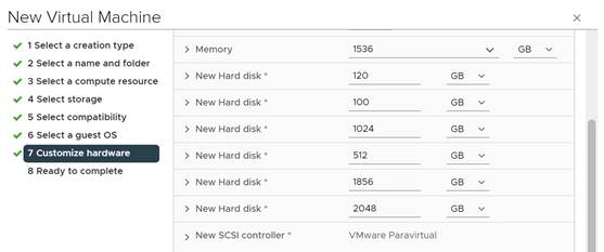
Step 29. Click Add New Device and from the drop-down list Network - Network Adapter.
Step 30. From the drop-down list of the new network select browse and AppServer.
Step 31. Add all required SAP HANA related networks by repeating steps 40 and 41.
Step 32. Change the New CD/DVD drive to Datastore ISO File and select your OS installation image.
Step 33. Select the checkmark field Connect, then click Next.
Step 34. Review the configuration details and click Finish.
Procedure 3. vSphere Clustering Service deployment
According to the SAP requirements non-SAP HANA VMs should not run on the same NUMA node where a productive SAP HANA VM is already running. In addition, no NUMA node sharing is allowed between SAP HANA and non-HANA virtual machines.
Step 1. Navigate to Inventory > Hosts and Clusters.
Step 2. Expand the cluster object (FlashStack-Management) and select the vHANA01 virtual machine.
Step 3. In the Summary - Tags field select Assign Tag.
Step 4. Select the SAP HANA tag and click Assign.
Procedure 4. Operating System Installation
The Linux operating system installations follows the Red Hat or SUSE specific installation guides:
● Red Hat Enterprise Linux 8 - Configuring RHEL 8 for SAP HANA 2 installation
● SUSE Linux Enterprise Server for SAP Applications 15 SP4 Guide
Step 1. Click Power On to start the virtual machine.
Step 2. Launch the web console.
Step 3. Follow the installation wizard. Detailed information on the installation process is available in the installation guides.
Step 4. Confirm the network adapter MAC address from the vHANA01 Summary tab in the VM Hardware - Network Adapter status page to ensure to configure the correct network adapter.
Step 5. When the installation finishes, reboot the machine.
Step 6. From the vHANA01 overview in the vSphere client, select Install VMware Tools.
Step 7. Click Actions > Guest OS - Install VMware Tools.
As soon as the vHANA virtual machine is up, vSphere will check the VM is compliant with the Anti-Affinity policy created before and move the vCLS virtual machine away from the host.
Step 8. Review the status in the vHANA virtual machine summary tab.
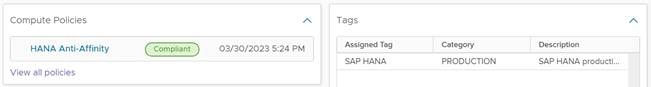
Procedure 5. Operating System configuration
The next step is manually defining the file systems before the operating system configuration and SAP HANA installation.
Step 1. SSH into the vHANA virtual machine as root.
Step 2. Find the available disks using the command:
[root@cishana01 ~]# lsblk
NAME MAJ:MIN RM SIZE RO TYPE MOUNTPOINT
sda 8:0 0 120G 0 disk
├─sda1 8:1 0 600M 0 part /boot/efi
├─sda2 8:2 0 1G 0 part /boot
└─sda3 8:3 0 118.4G 0 part
├─rhel-root 253:0 0 70G 0 lvm /
├─rhel-swap 253:1 0 4G 0 lvm [SWAP]
└─rhel-home 253:2 0 44.4G 0 lvm /home
sdb 8:16 0 100G 0 disk
sdc 8:32 0 1T 0 disk
sdd 8:48 0 512G 0 disk
sde 8:64 0 1.8T 0 disk
sdf 8:80 0 2T 0 disk
sr0 11:0 1 1024M 0 rom
Step 3. Create the required mount points:
mkdir -p /usr/sap
mkdir -p /hana/shared
mkdir -p /hana/log
mkdir -p /hana/data
Step 4. Construct an XFS filesystem on the new disks:
mkfs.xfs /dev/sdb
Step 5. Collect the universal unique identifier (UUID):
# blkid /dev/sdb
/dev/sdb: UUID="b02e42fa-ae35-41d1-a7f2-a2e6f45efb02" BLOCK_SIZE="512" TYPE="xfs"
Step 6. Add the mount point to the file system mount table (/etc/fstab) using the UUID:
echo UUID=b02e42fa-ae35-41d1-a7f2-a2e6f45efb02 /usr/sap xfs defaults, noatime 0 0 >> /etc/fstab
Step 7. Repeat steps 1 to 4 for the SAP HANA data, log, and shared volumes. Optionally for the backup volume as well.
Step 8. Mount the new mount points.
mount -a
Step 9. Update /etc/hosts with the IP addresses of all networks including their alias hostnames.
Make sure to configure the recommended operating system settings according to below SAP notes and apply the latest security patches to the new system before installing SAP HANA.
● SAP Note 277299 - Red Hat Enterprise Linux 8.x: Installation and Configuration
● SAP Note 2777782 - SAP HANA DB: Recommended OS Settings for RHEL 8
● SAP Note 2578899 - SUSE Linux Enterprise Server 15: Installation Note
● SAP Note 2684254 - SAP HANA DB: Recommended OS Settings for SLES 15 / SLES for SAP Applications 15
Procedure 6. SAP HANA installation
Please refer to the official SAP documentation which describes the SAP HANA installation process with and without the SAP unified installer.
● SAP HANA Server Installation and Update Guide
Afterwards, prepare additional virtual machines to install SAP S/4HANA or SAP BW/4HANA and follow the SAP master and installation guides.
A high-level overview of the FlashStack design validation is provided in this chapter. Solution validation explains various aspects of the converged infrastructure including compute, virtualization, network, and storage. The test scenarios are divided into the following broad categories:
● Functional validation – physical and logical setup validation
● Feature verification – feature verification for FlashStack design
● Availability testing – link and device redundancy and high availability testing
● Infrastructure as a code validation – verify automation and orchestration of solution components
● SAP HANA installation and validation – verify key performance indicator (KPI) metrics using the SAP HANA hardware and cloud measurement tool (HCMT)
The SAP HANA hardware and cloud measurement tool is generally available to measure configuration and performance of hardware and cloud systems intended for deployment of SAP HANA 2.0 and higher. For instructions on how to download, install and use of the SAP HCMT tools refer to the tools guide available on the SAP Help portal here: https://help.sap.com/viewer/product/HANA_HW_CLOUD_TOOLS/latest/en-US.
The goal of the solution validation is to test functional aspects of the design and unless explicitly called out, the performance and scalability is not explained during solution validation. However, limited load is always generated using tools such as HCMT, IOMeter and/or iPerf to help verify the test setup. Some of the examples of the types of tests executed include:
● Verification of features configured on various FlashStack components
● Powering off and rebooting redundant devices and removing redundant links to verify high availability
● Failure and recovery of vCenter and ESXi hosts in a cluster
● Verification of SAP HANA Anti-Affinity policy during vMotion of vHANA to a host running a vCLS instance.
● Failure and recovery of storage access paths across FlashArray controllers, MDS and Nexus switches, and fabric interconnects
● Load generation using SAP HANA VMs hosted on FlashStack components and path validation
As part of the validation effort, the solution validation team identifies the problems, works with the appropriate development teams to fix the problem, and provides work arounds, as necessary.
Conclusion
The FlashStack solution is a validated approach for deploying Cisco and Pure Storage technologies and products for building shared private and public cloud infrastructure. The best-in-class storage, server and networking components serve as the foundation for a variety of workloads not limited to SAP HANA TDI. The introduction of the Cisco UCS X-Series modular platform extends the FlashStack solution and allows customers to manage and orchestrate the current and next-generation Cisco UCS platform from the cloud using Cisco Intersight.
In addition to the Cisco UCS X-Series hardware and software innovations, the integration of the Cisco Intersight cloud platform with VMware vCenter and Pure Storage FlashArray delivers monitoring, orchestration, and workload optimization capabilities for the different layers (including virtualization and storage) of the FlashStack infrastructure. The modular nature of Cisco Intersight provides an easy upgrade path to additional services, such as workload optimization and Kubernetes.
The FlashStack solution with Cisco UCS X-Series and Cisco Intersight provides the following advantages over alternative solutions:
● A single platform built from unified compute, fabric, and storage technologies, allowing you to scale to large-scale data centers without architectural changes.
● Simpler and programmable infrastructure.
● Centralized, simplified management of all infrastructure resources, including the Pure Storage FlashArray and VMware vCenter by Cisco Intersight.
● Power and cooling innovations with Cisco UCS X-Series and better airflow.
● Fabric innovations for heterogeneous compute and memory composability.
● Innovative cloud operations providing continuous feature delivery.
● Future-ready design built for investment protection.
● Common OS and management tools ease network implementation, maintenance, and troubleshooting by relying on the same skill set across SAN, LAN, and computing environments.
● Nexus Dashboard Fabric Controller provides visibility into the network, servers, and storage resources and helps to provide full control of application SLAs and metrics beyond host and virtual machine monitoring.
● Smart Zoning reduces the need to implement and maintain large zone databases and eases management and implementation tasks.
● Organizations can interact with a single vendor when troubleshooting problems across computing, storage, and networking environments.
Joerg Wolters, Technical Marketing Engineer, Cisco Product Group – UCS and SAP solutions, Cisco Systems GmbH
Joerg has over ten years of experience at Cisco with data center, enterprise and service provider solution architectures and 20 years of SAP basis experience from operations, advanced services, performance tuning and SAP sizing. As a technical leader in Cisco CX support, Joerg helped many customers with support of their SAP HANA solutions leading and consulting the SAP HANA solution support teams. As a technical marketing engineer at the Cisco Product and Cisco UCS solutions group, Joerg focuses on network, compute, virtualization, storage, and orchestration aspects of various compute stacks.
Acknowledgements
For their support and contribution to the design, validation, and creation of this Cisco Validated Design, the authors would like to thank:
● Paniraja Koppa, Technical Marketing Engineer, Cisco Systems, Inc.
● Haseeb Niazi, Principal Technical Marketing Engineer, Cisco Systems, Inc.
● Joe Houghes, Senior Solution Architect, Pure Storage, Inc.
● Craig Waters, Technical Director, Pure Storage, Inc.
Appendix
This appendix contains the following:
● Appendix B - Reference used in this Guide
Red Hat Ansible Automation Platform:
https://www.redhat.com/en/technologies/management/ansible
GitHub repository for solution deployment:
https://github.com/ucs-compute-solutions/FlashStack_IMM_Ansible
Pipenv: Python Dev Workflow for Humans:
https://pipenv-fork.readthedocs.io/en/latest
Cisco Intersight Ansible Collection:
https://github.com/CiscoDevNet/intersight-ansible
Cisco NX-OS Ansible Collection:
https://galaxy.ansible.com/cisco/nxos
Pure Storage FlashArray Ansible Collection:
https://galaxy.ansible.com/purestorage/flasharray
VMware Ansible Collection:
https://galaxy.ansible.com/community/vmware
SAP module collection for Ansible:
https://github.com/sap-linuxlab/community.sap_libs
Appendix B – References Used in this Guide
Compute
FlashStack for SAP HANA TDI with Cisco UCS M6 X-Series:
https://www.cisco.com/c/en/us/td/docs/unified_computing/ucs/UCS_CVDs/flashstack_ucs_xseries_sap_hana_tdi_design.html
FlashStack Virtual Server Infrastructure with Cisco UCS X-Series and VMware 7.0 U2:
https://www.cisco.com/c/en/us/td/docs/unified_computing/ucs/UCS_CVDs/flashstack_vsi_vmware70_ucsx.html
Cisco Intersight Managed Mode Configuration Guide:
https://www.intersight.com/help/saas/resources/cisco_intersight_managed_mode_configuration#introduction
Performance Tuning Guide for Cisco UCS M6 Servers:
https://www.cisco.com/c/en/us/products/collateral/servers-unified-computing/ucs-b-series-blade-servers/performance-tuning-guide-ucs-m6-servers.html
Performance Tuning Guide for Cisco UCS M5 Servers:
https://www.cisco.com/c/en/us/products/collateral/servers-unified-computing/ucs-b-series-blade-servers/white-paper-c11-744678.html
Cisco UCS tools:
https://intersight.com/help/saas/resources/cisco_ucs_tools#about_cisco_ucs_tools
Storage
FlashArray VMware Best Practices:
https://support.purestorage.com/Solutions/VMware_Platform_Guide/User_Guides_for_VMware_Solutions/FlashArray_VMFS_RDM_VMware_Best_Practices_User_Guide/hhhWeb_Guide%3A_FlashArray_VMware_Best_Practices
Using the Pure Storage Plugin for the vSphere Client:
https://support.purestorage.com/Solutions/VMware_Platform_Guide/User_Guides_for_VMware_Solutions/Using_the_Pure_Storage_Plugin_for_the_vSphere_Client
vSphere Plugin User Guide: Installing the remote vSphere Plugin with the Pure Storage VMware appliance:
https://support.purestorage.com/Solutions/VMware_Platform_Guide/User_Guides_for_VMware_Solutions/Using_the_Pure_Storage_Plugin_for_the_vSphere_Client/vSphere_Plugin_User_Guide%3A_Installing_the_Remote_vSphere_Plugin_with_the_Pure_Storage_VMware_Appliance
vVols User Guide: The FlashArray VASA Provider:
https://support.purestorage.com/Solutions/VMware_Platform_Guide/User_Guides_for_VMware_Solutions/Virtual_Volumes_User_Guide/vVols_User_Guide%3A__The_FlashArray_VASA_Provider
FlashArray File Services:
https://support.purestorage.com/FlashArray/PurityFA/FlashArray_File_Services
VMware
SAP HANA on VMware vSphere Best Practices and Reference Architecture Guide:
https://core.vmware.com/resource/sap-hana-vmware-vsphere-best-practices-and-reference-architecture-guide
SAP HANA on VMware vSphere:
https://wiki.scn.sap.com/wiki/display/VIRTUALIZATION/SAP+HANA+on+VMware+vSphere
Recover the Secure ESXi configuration:
https://docs.vmware.com/en/VMware-vSphere/7.0/com.vmware.vsphere.security.doc/GUID-23FFB8BB-BD8B-46F1-BB59-D716418E889A.html
VMware Cisco custom image for ESXi 7.0 U3:
https://customerconnect.vmware.com/downloads/details?downloadGroup=OEM-ESXI70U3-CISCO&productId=974
VMware vCenter Server 7.0U3:
https://customerconnect.vmware.com/downloads/details?downloadGroup=VC70U3H&productId=974&rPId=95488
SAP HANA on VMware vSphere 7.0 in production:
SAP Note 2937606
Red Hat
Red Hat Enterprise Linux 8 - Configuring RHEL 8 for SAP HANA 2 installation:
https://access.redhat.com/documentation/de-de/red_hat_enterprise_linux/8/html/configuring_rhel_8_for_sap_hana_2_installation/index
Red Hat Enterprise Linux 8.x: Installation and Configuration:
SAP Note 277299
SAP HANA DB: Recommended OS Settings for RHEL 8:
SAP Note 2777782
SUSE
SUSE Linux Enterprise Server for SAP Applications 15 SP4 Guide:
https://documentation.suse.com/sles-sap/15-SP4/html/SLES-SAP-guide/index.html
SUSE Linux Enterprise Server 15: Installation Note:
SAP Note 2578899
SAP HANA DB: Recommended OS Settings for SLES 15 / SLES for SAP Applications 15:
SAP Note 2684254
SAP HANA
SAP HANA Server installation and update guide:
https://help.sap.com/docs/SAP_HANA_PLATFORM/2c1988d620e04368aa4103bf26f17727/7eb0167eb35e4e2885415205b8383584.html
SAP HANA network requirements white paper:
https://www.sap.com/documents/2016/08/1cd2c2fb-807c-0010-82c7-eda71af511fa.html
SAP HANA Hardware and Cloud Measurement Tools:
https://help.sap.com/docs/HANA_HW_CLOUD_TOOLS/02bb1e64c2ae4de7a11369f4e70a6394/7e878f6e16394f2990f126e639386333.html
SAP HANA: Supported Operating Systems:
SAP note 2235581
Interoperability Matrix
Cisco UCS Hardware and Software Compatibility:
https://ucshcltool.cloudapps.cisco.com/public/
Interoperability Matrix for Cisco Nexus and MDS 9000 products:
https://www.cisco.com/c/en/us/td/docs/switches/datacenter/mds9000/interoperability/matrix/intmatrx.html
Pure Storage Interoperability Matrix (Requires a Pure Storage support login):
https://support.purestorage.com/FlashArray/Getting_Started/Compatibility_Matrix
Pure Storage FlashStack Compatibility Matrix (requires a Pure Storage support login):
https://support.purestorage.com/FlashStack/Product_Information/FlashStack_Compatibility_Matrix
SAP HANA supported server and storage systems:
https://www.sap.com/dmc/exp/2014-09-02-hana-hardware/enEN/#/solutions?filters=ve:1;ve:18
VMware Compatibility Guide:
https://www.vmware.com/resources/compatibility/search.php?deviceCategory=server&details=1&partner=146&releases=578&cpuSeries=128,147,129,146,130,148&page=1&display_interval=10&sortColumn=Partner&sortOrder=Asc
Appendix C – Glossary
This glossary addresses some terms used in this document, for the purposes of aiding understanding. This is not a complete list of all multicloud terminology. Some Cisco product links are supplied here also, where considered useful for the purposes of clarity, but this is by no means intended to be a complete list of all applicable Cisco products.
| Ansible |
An infrastructure automation tool, used to implement processes for instantiating and configuring IT service components, such as VMs on an IaaS platform. Supports the consistent execution of processes defined in YAML “playbooks” at scale, across multiple targets. Because the Ansible artefacts (playbooks) are text-based, they can be stored in a Source Code Management (SCM) system, such as GitHub. This allows for software development like processes to be applied to infrastructure automation, such as, Infrastructure-as-code (see IaC below). |
| Co-located data center |
“A colocation center (CoLo)…is a type of data center where equipment, space, and bandwidth are available for rental to retail customers. Colocation facilities provide space, power, cooling, and physical security for the server, storage, and networking equipment of other firms and also connect them to a variety of telecommunications and network service providers with a minimum of cost and complexity.” |
| DevOps |
The underlying principle of DevOps is that the application development and operations teams should work closely together, ideally within the context of a toolchain that automates the stages of development, test, deployment, monitoring, and issue handling. DevOps is closely aligned with IaC, continuous integration and deployment (CI/CD), and Agile software development practices. |
| IaC (Infrastructure as-Code) |
Given the ability to automate aaS via APIs, the implementation of the automation is typically via Python code, Ansible playbooks, and similar. These automation artefacts are programming code that define how the services are consumed. As such, they can be subject to the same code management and software development regimes as any other body of code. This means that infrastructure automation can be subject to all of the quality and consistency benefits, CI/CD, traceability, automated testing, compliance checking, and so on, that could be applied to any coding project. |
| IAM (Identity and Access Management) |
IAM is the means to control access to IT resources so that only those explicitly authorized to access given resources can do so. IAM is an essential foundation to a secure multicloud environment. |
| Intersight |
Cisco Intersight™ is a Software-as-a-Service (SaaS) infrastructure lifecycle management platform that delivers simplified configuration, deployment, maintenance, and support. https://www.cisco.com/c/en/us/products/servers-unified-computing/intersight/index.html |
| PaaS (Platform-as-a-Service) |
PaaS is a layer of value-add services, typically for application development, deployment, monitoring, and general lifecycle management. The use of IaC with IaaS and PaaS is very closely associated with DevOps practices. |
| Private on-premises data center |
A data center infrastructure housed within an environment owned by a given enterprise is distinguished from other forms of data center, with the implication that the private data center is more secure, given that access is restricted to those authorized by the enterprise. Thus, circumstances can arise where very sensitive IT assets are only deployed in a private data center, in contrast to using public IaaS. For many intents and purposes, the underlying technology can be identical, allowing for hybrid deployments where some IT assets are privately deployed but also accessible to other assets in public IaaS. IAM, VPNs, firewalls, and similar are key technologies needed to underpin the security of such an arrangement. |
| REST API |
Representational State Transfer (REST) APIs is a generic term for APIs accessed over HTTP(S), typically transporting data encoded in JSON or XML. REST APIs have the advantage that they support distributed systems, communicating over HTTP, which is a well-understood protocol from a security management perspective. REST APIs are another element of a cloud-native applications architecture, alongside microservices. https://en.wikipedia.org/wiki/Representational_state_transfer |
| SaaS (Software-as-a-Service) |
End-user applications provided “aaS” over the public Internet, with the underlying software systems and infrastructure owned and managed by the provider. |
| SAML (Security Assertion Markup Language) |
Used in the context of Single-Sign-On (SSO) for exchanging authentication and authorization data between an identity provider, typically an IAM system, and a service provider (some form of SaaS). The SAML protocol exchanges XML documents that contain security assertions used by the aaS for access control decisions. https://en.wikipedia.org/wiki/Security_Assertion_Markup_Language |
ACP—Access-Control Policy
AD—Microsoft Active Directory
API—Application Programming Interface
CDP—Cisco Discovery Protocol
CPU—Central Processing Unit
CVD—Cisco Validated Design
DC—Data Center
DHCP—Dynamic Host Configuration Protocol
DMZ—Demilitarized Zone (firewall/networking construct)
DNS—Domain Name System
GbE—Gigabit Ethernet
Gbit/s—Gigabits Per Second (interface/port speed reference)
HA—High-Availability
IP—Internet Protocol
IPAM—IP Address Management
LACP—Link Aggregation Control Protocol
LAG—Link Aggregation Group
LAN—Local Area Network
L2 VNI—Layer 2 Virtual Network Identifier; as used in SD-Access Fabric, a VLAN.
L3 VNI— Layer 3 Virtual Network Identifier; as used in SD-Access Fabric, a VRF.
MAC—Media Access Control Address (OSI Layer 2 Address)
MTU—Maximum Transmission Unit
QoS—Quality of Service
REST—Representational State Transfer
RTT—Round-Trip Time
SD—Software-Defined
SDN—Software-Defined Networking
SFP—Small Form-Factor Pluggable (1 GbE transceiver)
SFP+— Small Form-Factor Pluggable (10 GbE transceiver)
STP—Spanning-tree protocol
Syslog—System Logging Protocol
TCP—Transmission Control Protocol (OSI Layer 4)
UCS— Cisco Unified Computing System
URL—Uniform Resource Locator
VLAN—Virtual Local Area Network
VM—Virtual Machine
vPC—virtual Port Channel (Cisco Nexus)
VRF—Virtual Routing and Forwarding
VXLAN—Virtual Extensible LAN
For comments and suggestions about this guide and related guides, join the discussion on Cisco Community at https://cs.co/en-cvds.
CVD Program
ALL DESIGNS, SPECIFICATIONS, STATEMENTS, INFORMATION, AND RECOMMENDATIONS (COLLECTIVELY, "DE-SIGNS") IN THIS MANUAL ARE PRESENTED "AS IS," WITH ALL FAULTS. CISCO AND ITS SUPPLIERS DISCLAIM ALL WAR-RANTIES, INCLUDING, WITHOUT LIMITATION, THE WARRANTY OF MERCHANTABILITY, FITNESS FOR A PARTICULAR PURPOSE AND NONINFRINGEMENT OR ARISING FROM A COURSE OF DEALING, USAGE, OR TRADE PRACTICE. IN NO EVENT SHALL CISCO OR ITS SUPPLIERS BE LIABLE FOR ANY INDIRECT, SPECIAL, CONSEQUENTIAL, OR INCIDENTAL DAMAGES, INCLUDING, WITHOUT LIMITATION, LOST PROFITS OR LOSS OR DAMAGE TO DATA ARISING OUT OF THE USE OR INABILITY TO USE THE DESIGNS, EVEN IF CISCO OR ITS SUPPLIERS HAVE BEEN ADVISED OF THE POSSIBILITY OF SUCH DAMAGES.
THE DESIGNS ARE SUBJECT TO CHANGE WITHOUT NOTICE. USERS ARE SOLELY RESPONSIBLE FOR THEIR APPLICA-TION OF THE DESIGNS. THE DESIGNS DO NOT CONSTITUTE THE TECHNICAL OR OTHER PROFESSIONAL ADVICE OF CISCO, ITS SUPPLIERS OR PARTNERS. USERS SHOULD CONSULT THEIR OWN TECHNICAL ADVISORS BEFORE IMPLE-MENTING THE DESIGNS. RESULTS MAY VARY DEPENDING ON FACTORS NOT TESTED BY CISCO.
CCDE, CCENT, Cisco Eos, Cisco Lumin, Cisco Nexus, Cisco StadiumVision, Cisco TelePresence, Cisco WebEx, the Cisco logo, DCE, and Welcome to the Human Network are trademarks; Changing the Way We Work, Live, Play, and Learn and Cisco Store are service marks; and Access Registrar, Aironet, AsyncOS, Bringing the Meeting To You, Catalyst, CCDA, CCDP, CCIE, CCIP, CCNA, CCNP, CCSP, CCVP, Cisco, the Cisco Certified Internetwork Expert logo, Cisco IOS, Cisco Press, Cisco Systems, Cisco Systems Capital, the Cisco Systems logo, Cisco Unified Computing System (Cisco UCS), Cisco UCS B-Series Blade Servers, Cisco UCS C-Series Rack Servers, Cisco UCS S-Series Storage Servers, Cisco UCS Manager, Cisco UCS Management Software, Cisco Unified Fabric, Cisco Application Centric Infrastructure, Cisco Nexus 9000 Series, Cisco Nexus 7000 Series. Cisco Prime Data Center Network Manager, Cisco NX-OS Software, Cis-co MDS Series, Cisco Unity, Collaboration Without Limitation, EtherFast, EtherSwitch, Event Center, Fast Step, Follow Me Browsing, FormShare, GigaDrive, HomeLink, Internet Quotient, IOS, iPhone, iQuick Study, LightStream, Linksys, MediaTone, MeetingPlace, MeetingPlace Chime Sound, MGX, Networkers, Networking Academy, Network Registrar, PCNow, PIX, PowerPanels, ProConnect, ScriptShare, SenderBase, SMARTnet, Spectrum Expert, StackWise, The Fastest Way to Increase Your Internet Quotient, TransPath, WebEx, and the WebEx logo are registered trade-marks of Cisco Systems, Inc. and/or its affiliates in the United States and certain other countries. (LDW_P8)
All other trademarks mentioned in this document or website are the property of their respective owners. The use of the word partner does not imply a partnership relationship between Cisco and any other company. (0809R)