FlashStack Data Center for Oracle RAC 19c Database on NVMe/RoCE
Available Languages
Bias-Free Language
The documentation set for this product strives to use bias-free language. For the purposes of this documentation set, bias-free is defined as language that does not imply discrimination based on age, disability, gender, racial identity, ethnic identity, sexual orientation, socioeconomic status, and intersectionality. Exceptions may be present in the documentation due to language that is hardcoded in the user interfaces of the product software, language used based on RFP documentation, or language that is used by a referenced third-party product. Learn more about how Cisco is using Inclusive Language.
- US/Canada 800-553-2447
- Worldwide Support Phone Numbers
- All Tools
 Feedback
 Feedback

FlashStack Data Center for Oracle RAC 19c Database on NVMe/RoCE
Deployment Guide for Oracle RAC 19c Databases on Cisco UCS with Pure Storage FlashArray//X90 R2 on NVMe over RoCE (RDMA over Converged Ethernet v2)
Published: August 2021

In partnership with:
![]()
About the Cisco Validated Design Program
The Cisco Validated Design (CVD) program consists of systems and solutions designed, tested, and documented to facilitate faster, more reliable, and more predictable customer deployments. For more information, go to:
http://www.cisco.com/go/designzone.
ALL DESIGNS, SPECIFICATIONS, STATEMENTS, INFORMATION, AND RECOMMENDATIONS (COLLECTIVELY, "DESIGNS") IN THIS MANUAL ARE PRESENTED "AS IS," WITH ALL FAULTS. CISCO AND ITS SUPPLIERS DISCLAIM ALL WARRANTIES, INCLUDING, WITHOUT LIMITATION, THE WARRANTY OF MERCHANTABILITY, FITNESS FOR A PARTICULAR PURPOSE AND NONINFRINGEMENT OR ARISING FROM A COURSE OF DEALING, USAGE, OR TRADE PRACTICE. IN NO EVENT SHALL CISCO OR ITS SUPPLIERS BE LIABLE FOR ANY INDIRECT, SPECIAL, CONSEQUENTIAL, OR INCIDENTAL DAMAGES, INCLUDING, WITHOUT LIMITATION, LOST PROFITS OR LOSS OR DAMAGE TO DATA ARISING OUT OF THE USE OR INABILITY TO USE THE DESIGNS, EVEN IF CISCO OR ITS SUPPLIERS HAVE BEEN ADVISED OF THE POSSIBILITY OF SUCH DAMAGES.
THE DESIGNS ARE SUBJECT TO CHANGE WITHOUT NOTICE. USERS ARE SOLELY RESPONSIBLE FOR THEIR APPLICATION OF THE DESIGNS. THE DESIGNS DO NOT CONSTITUTE THE TECHNICAL OR OTHER PROFESSIONAL ADVICE OF CISCO, ITS SUPPLIERS OR PARTNERS. USERS SHOULD CONSULT THEIR OWN TECHNICAL ADVISORS BEFORE IMPLEMENTING THE DESIGNS. RESULTS MAY VARY DEPENDING ON FACTORS NOT TESTED BY CISCO.
CCDE, CCENT, Cisco Eos, Cisco Lumin, Cisco Nexus, Cisco StadiumVision, Cisco TelePresence, Cisco WebEx, the Cisco logo, DCE, and Welcome to the Human Network are trademarks; Changing the Way We Work, Live, Play, and Learn and Cisco Store are service marks; and Access Registrar, Aironet, AsyncOS, Bringing the Meeting To You, Catalyst, CCDA, CCDP, CCIE, CCIP, CCNA, CCNP, CCSP, CCVP, Cisco, the Cisco Certified Internetwork Expert logo, Cisco IOS, Cisco Press, Cisco Systems, Cisco Systems Capital, the Cisco Systems logo, Cisco Unified Computing System (Cisco UCS), Cisco UCS B-Series Blade Servers, Cisco UCS C-Series Rack Servers, Cisco UCS S-Series Storage Servers, Cisco UCS Manager, Cisco UCS Management Software, Cisco Unified Fabric, Cisco Application Centric Infrastructure, Cisco Nexus 9000 Series, Cisco Nexus 7000 Series. Cisco Prime Data Center Network Manager, Cisco NX-OS Software, Cisco MDS Series, Cisco Unity, Collaboration Without Limitation, EtherFast, EtherSwitch, Event Center, Fast Step, Follow Me Browsing, FormShare, GigaDrive, HomeLink, Internet Quotient, IOS, iPhone, iQuick Study, LightStream, Linksys, MediaTone, MeetingPlace, MeetingPlace Chime Sound, MGX, Networkers, Networking Academy, Network Registrar, PCNow, PIX, PowerPanels, ProConnect, ScriptShare, SenderBase, SMARTnet, Spectrum Expert, StackWise, The Fastest Way to Increase Your Internet Quotient, TransPath, WebEx, and the WebEx logo are registered trademarks of Cisco Systems, Inc. and/or its affiliates in the United States and certain other countries. (LDW_P).
All other trademarks mentioned in this document or website are the property of their respective owners. The use of the word partner does not imply a partnership relationship between Cisco and any other company. (0809R)
© 2021 Cisco Systems, Inc. All rights reserved.
Deployment Hardware and Software
Operating System and Database Deployment
The IT industry has been transforming rapidly to converged infrastructure, which enables faster provisioning, scalability, lower data center costs, simpler management infrastructure with technology advancement. There is a current industry trend for pre-engineered solutions which standardize the data center infrastructure and offers operational efficiencies and agility to address enterprise applications and IT services. This standardized data center needs to be seamless instead of siloed when spanning multiple sites, delivering a uniform network and storage experience to the compute systems and end users accessing these data centers.
The FlashStack solution provides best of breed technology from Cisco Unified Computing System and Pure Storage to gain the benefits that converged infrastructure brings to the table. FlashStack solution provides the advantage of having the compute, storage, and network stack integrated with the programmability of the Cisco Unified Computing System (Cisco UCS). Cisco Validated Designs (CVDs) consist of systems and solutions that are designed, tested, and documented to facilitate and improve customer deployments. These designs incorporate a wide range of technologies and products into a portfolio of solutions that have been developed to address the business needs of customers and to guide them from design to deployment.
This Cisco Validated Design (CVD) describes a FlashStack reference architecture for deploying a highly available Oracle Multitenant RAC 19c Databases environment on Pure Storage FlashArray//X90 R2 using Cisco UCS Compute Servers, Cisco Fabric Interconnect Switches, Cisco Nexus Switches and Red Hat Enterprise Linux. Cisco and Pure Storage have validated the reference architecture with various Database workloads like OLTP (Online Transactional Processing) and Data Warehouse in Cisco’s UCS Datacenter lab. This document presents the hardware and software configuration of the components involved, results of various tests performed and offers implementation and best practices guidance.
Introduction
This Cisco Validated Design (CVD) describes how Cisco UCS System can be used in conjunction with Pure Storage FlashArray //X90 R2 System to implement an Oracle Multitenant Real Application Cluster (RAC) 19c Database solution on NVMe over RoCE (RDMA over Converged Ethernet). Oracle Multitenant is a new option starting with Oracle Database 12c Enterprise Edition that helps customers reduce IT costs by simplifying consolidation, provisioning, upgrades, and more. The Oracle Multitenant architecture allows a container database to hold many pluggable databases and it fully complements other options, including Oracle Real Application Clusters and Oracle Active Data Guard.
FlashStack embraces the latest technology and efficiently simplifies data center workloads that redefine the way IT delivers value:
· A cohesive, integrated system that is managed, serviced and tested as a whole
· Guarantee customer success with prebuilt, pre-tested drivers and Oracle database software
· Faster Time to Deployment – Leverage a pre-validated platform to minimize business disruption, improve IT agility, and reduce deployment time from months to weeks.
· Reduces Operational Risk – Highly available architecture with no single point of failure, non-disruptive operations, and no downtime.
Audience
The target audience for this document includes but is not limited to storage administrators, data center architects, database administrators, field consultants, IT managers, Oracle solution architects and customers who want to implement Oracle RAC database solutions with Red Hat Enterprise Linux on a FlashStack Converged Infrastructure solution. A working knowledge of Oracle RAC Database, Linux, Storage technology, and Network is assumed but is not a prerequisite to read this document
Purpose of this Document
Oracle RAC database often manage the mission critical components of a customer’s IT department. Ensuring availability while lowering the IT department’s TCO is always the database administrator’s top priority. This FlashStack solution for Oracle RAC databases delivers industry-leading storage, unprecedented scalability, high availability and simplified operational management for customers and their business demands. The goal of this Cisco Validated Design (CVD) is to highlight the performance, scalability, manageability, and high availability for OLTP and OLAP type of Oracle Databases on the FlashStack CI Solution.
The following are the objectives of this reference architecture document:
· Provide reference architecture design guidelines for deploying Oracle RAC Databases on FlashStack.
· Build, validate, and predict performance of Server, Network, and Storage platform on various types of workload
· Demonstrate the seamless scalability of performance and capacity to meet growth needs of Oracle Databases.
· Confirm high availability of Database instances, without performance compromise through software and hardware upgrades.
Starting from Oracle Database release 12c onwards, there are two ways to create a database, as a multitenant database or a pre-12c non-multitenant database. In this solution, we will deploy both types of databases (Non-Container Database and Container Database) and perform testing on various types of workloads to check how performance on both aspects of it. We will demonstrate the scalability and performance of this solution by running database stress tests such as SwingBench and SLOB (Silly Little Oracle Benchmark) on OLTP (Online Transaction Processing) and DSS (Decision Support System) databases with varying users, nodes and read/write workload characteristics.
What’s New in this Release?
This version of the FlashStack CVD introduces the Pure Storage DirectFlash™ Fabric that brings the low latency and high performance of NVMe technology to the storage network along with Cisco UCS 5th Generation B200 M5 Blade Servers to deploy Oracle RAC Database Releases 19c using RDMA over Converged Ethernet (RoCE).
It incorporates the following features:
· Cisco UCS B200 M5 Blade Servers with 2nd Generation Intel® Xeon™ Scalable Processors
· Validation of Oracle RAC 19c Container and Non-Container Database deployments
· Support for the NVMe/RoCE on Cisco UCS and Pure Storage
· Support for the Cisco UCS Infrastructure and UCS Manager Software Release 4.1
· 100Gbps NVMe/RoCE Storage to Nexus Switch Connectivity
Solution Summary
NVMe is a host controller interface and storage protocol that was created by an industry body called NVM Express Inc as a replacement for SCSI/SAS and SATA. It enables fast transfer of data over a computer’s high-speed Peripheral Component Interconnect Express (PCIe) bus. It was designed from the ground up for low-latency solid state media, eliminating many of the bottlenecks seen in the legacy protocols for running enterprise applications.
NVMe devices are connected to the PCIe bus inside a server. NVMe-oF extends the high-performance and low-latency benefits of NVMe across network fabrics that connect servers and storage. NVMe-oF takes the lightweight and streamlined NVMe command set, and the more efficient queueing model, and replaces the PCIe transport with alternate transports, like Fibre Channel, RDMA over Converged Ethernet (RoCE v2), TCP.
Remote Direct Memory Access (RDMA) is the ability of accessing (read, write) memory on a remote machine without interrupting the processing of the CPU(s) on that system. Remote Direct Memory Access (RDMA) provides direct memory access from the memory of one host (storage or compute) to the memory of another host without involving the remote Operating System and CPU, boosting network and host performance with lower latency, lower CPU load and higher bandwidth. RoCE (RDMA over Converged Ethernet, pronounced Rocky) provides a seamless, low overhead, scalable way to solve the TCP/IP I/O bottleneck with minimal extra infrastructure.
NVMe-oF provides better performance for the following reasons:
· Lower latency
· Higher IOPs
· Higher bandwidth
· Improved protocol efficiency by reducing the I/O stack
· Lower CPU utilization on the host by offloading some processing from the kernel to the HBA.
RDMA over Converged Ethernet (RoCE) is a standard protocol which enables RDMA’s efficient data transfer over Ethernet networks allowing transport offload with hardware RDMA engine implementation, and superior performance. RoCE is a standard protocol defined in the InfiniBand Trade Association (IBTA) standard. RoCE v2 makes use of UDP encapsulation allowing it to transcend Layer 3 networks.
In this FlashStack solution, we will showcase Cisco UCS System with Pure’s FlashArray//X90 R2 running on NVMe-oF which can provide efficiency and performance of NVMe, and the benefits of shared accelerated storage with advanced data services like redundancy, thin provisioning, snapshots and replication.
The FlashStack platform, developed by Cisco and Pure Storage, is a flexible, integrated infrastructure solution that delivers pre-validated storage, networking, and server technologies. Composed of defined set of hardware and software, this FlashStack solution is designed to increase IT responsiveness to organizational needs and reduce the cost of computing with maximum uptime and minimal risk. Cisco and Pure Storage have carefully validated and verified the FlashStack solution architecture and its many use cases while creating a portfolio of detailed documentation, information, and references to assist customers in transforming their data centers to this shared infrastructure model.
This portfolio includes, but is not limited to, the following items:
· Best practice architectural design
· Implementation and deployment instructions and provides application sizing based on results
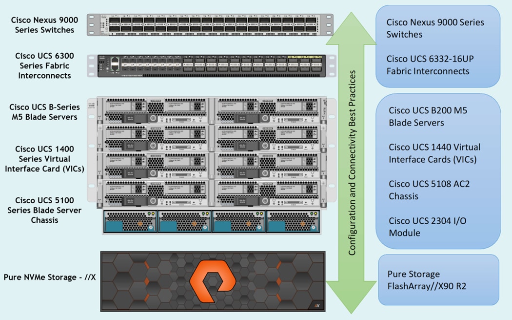
As shown in Figure 1, these components are connected and configured according to best practices of both Cisco and Pure Storage and provides the ideal platform for running a variety of enterprise database workloads with confidence. FlashStack can scale up for greater performance and capacity (adding compute, network, or storage resources individually as needed), or it can scale out for environments that require multiple consistent deployments.
The reference architecture covered in this document leverages the Pure Storage FlashArray//X90 R2 Controller with NVMe based DirectFlash™ Fabric for Storage, Cisco UCS B200 M5 Blade Server for Compute, Cisco Nexus 9000 series Switches for the networking element and Cisco Fabric Interconnects 6300 series for System Management. As shown in Figure 1, FlashStack Architecture can maintain consistency at scale. Each of the component families shown in (Cisco UCS, Cisco Nexus, Cisco FI and Pure Storage) offers platform and resource options to scale the infrastructure up or down, while supporting the same features and functionality that are required under the configuration and connectivity best practices of FlashStack.
FlashStack provides a jointly supported solution by Cisco and Pure Storage. Bringing a carefully validated architecture built on superior compute, world-class networking, and the leading innovations in all flash storage. The portfolio of validated offerings from FlashStack includes but is not limited to the following:
· Consistent Performance and Scalability
· Operational Simplicity
· Mission Critical and Enterprise Grade Resiliency
Cisco and Pure Storage have also built a robust and experienced support team focused on FlashStack solutions, from customer account and technical sales representatives to professional services and technical support engineers. The support alliance between Pure Storage and Cisco gives customers and channel services partners direct access to technical experts who collaborate with cross vendors and have access to shared lab resources to resolve potential issues.
Deployment Hardware and Software
This FlashStack solution provides an end-to-end architecture with Cisco Unified Computing System, Oracle, and Pure Storage technologies and demonstrates the benefits for running Oracle Multitenant RAC Databases 19c workload with high availability and redundancy. The reference FlashStack architecture covered in this document is built on the Pure Storage FlashArray//X90 R2 Series for Storage, Cisco UCS B200 M5 Blade Servers for Compute, Cisco Nexus 9336C-FX2 Switches for Network and Cisco Fabric Interconnects 6332-16UP Fabric Interconnects for System Management in a single package. The design is flexible enough that the networking, computing, and storage can fit in one data center rack or be deployed according to a customer's data center design. The reference architecture reinforces the "wire-once" strategy, because as additional storage is added to the architecture, no re-cabling is required from the hosts to the Cisco UCS fabric interconnect.
Physical Topology
This solution consists of the following set of hardware combined into a single stack as:
· Compute: Cisco UCS B200 M5 Blade Servers with Cisco Virtual Interface Cards (VIC) 1440
· Network: Cisco Nexus 9336C-FX2 and Cisco UCS Fabric Interconnect 6332-16UP for network and management connectivity
· Storage: Pure Storage FlashArray //X90 R2
In this solution design, two Cisco UCS Blade Server Chassis were used with 8 identical Intel Xeon CPU based Cisco UCS B200 M5 Blade Servers for hosting the 8-Node Oracle RAC Databases. The Cisco UCS B200 M5 Server has Virtual Interface Card (VIC) 1440 with port expander and they were connected four ports from each Cisco Fabric extender 2304 of the Cisco UCS Chassis to the Cisco Fabric Interconnects, which were in turn connected to the Cisco Nexus Switches for upstream connectivity to access the Pure storage.
Figure 2 shows the architecture diagram of the components and the network connections to deploy an eight node Oracle RAC 19c Databases solution. This reference design is a typical network configuration that can be deployed in a customer's environments. The best practices and setup recommendations are described later in this document.
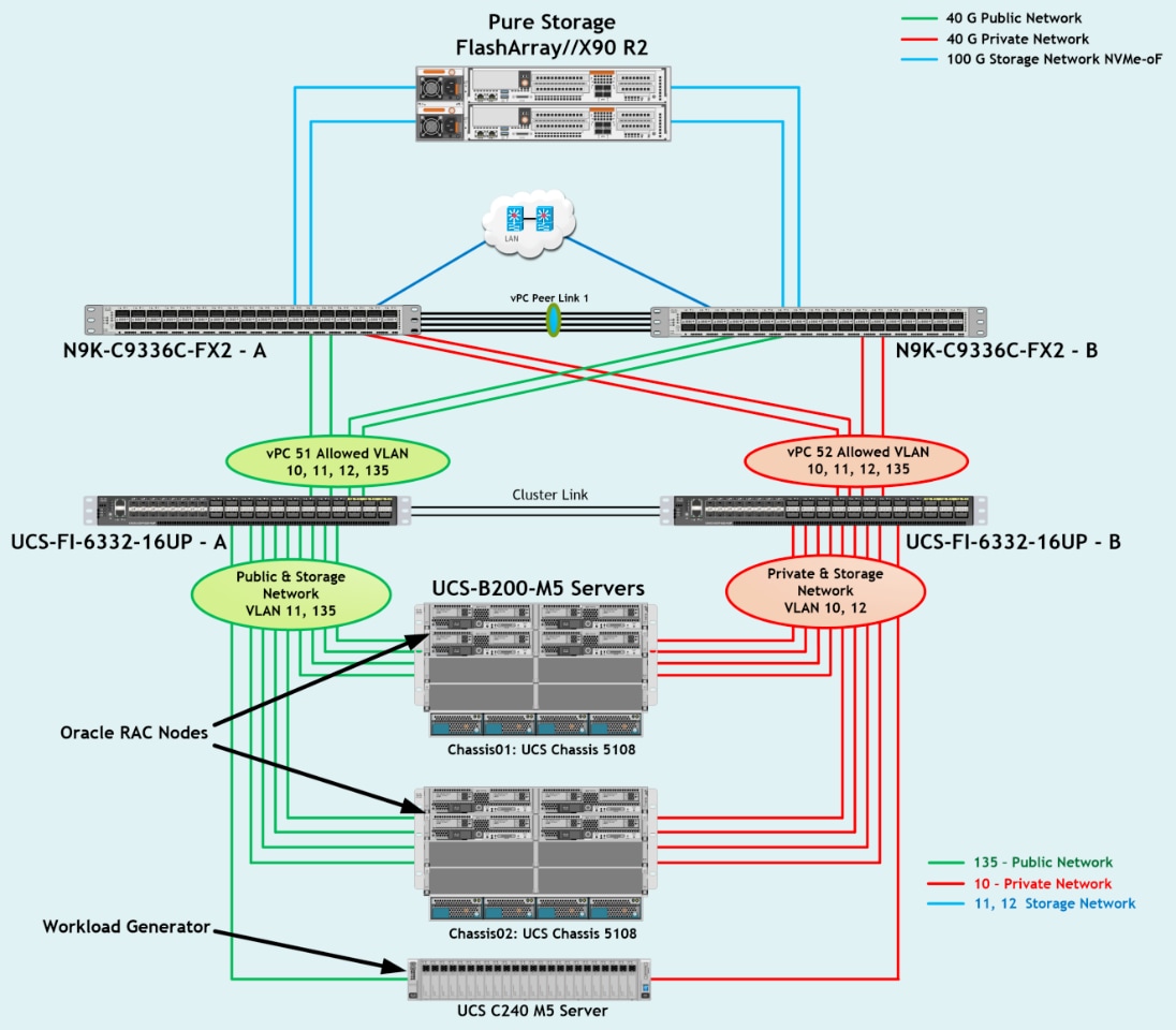
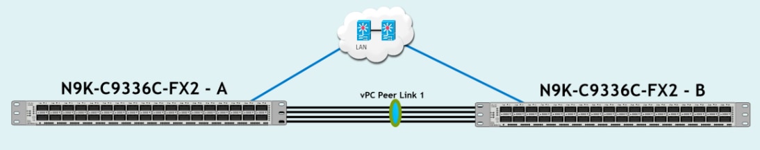
As shown in Figure 2, a pair of the Cisco UCS 6332-16UP Fabric Interconnects (FI) carries both storage and network traffic from the Cisco UCS B200 M5 server blades with the help of Cisco Nexus 9336C-FX2 Switches. Both the Fabric Interconnects and the Cisco Nexus switches are clustered with the peer link between them to provide high availability. Three virtual Port-Channels (vPCs) are configured to provide public network, private network and storage network paths for the server blades to northbound switches and storage to provide aggregated bandwidth and redundancy. Each vPC has VLANs created for application network data, storage data and management data paths.
As illustrated in the architecture, eight (4 x 40G link per chassis) links from the Blade Server Chassis go to Fabric Interconnect – A. Similarly, eight (4 x 40G link per chassis) links from the Blade Server Chassis go to Fabric Interconnect – B. Fabric Interconnect – A links are used for Oracle Public Network Traffic (VLAN-135) and Storage Network Traffic (VLAN-11) shown as green lines. Fabric Interconnect – B links are used for Oracle Private Interconnect Traffic (VLAN 10) and Storage Network Traffic (VLAN-12) shown as red lines.
From Fabric Interconnect – A, two 40G links go to Nexus Switch – A and two 40G links go to Nexus Switch – B which is configured as Port-Channel (vPC 51). Similarly, From Fabric Interconnect – B, two 40G links go to Nexus Switch – A and two 40G links go to Nexus Switch – B which is configured as Port-Channel (vPC 52). From Nexus Switch – A, one 100G link goes to Pure Storage Controller CT0 and one 100G link goes to Pure Storage Controller CT1 shown as blue lines. Likewise, from Nexus Switch – B, one 100G link goes to Pure Storage Controller CT0 and one 100G link goes to Pure Storage Controller CT1 shown as blue lines. Storage access from Nexus Switch – A and Nexus Switch –B show as blue lines. This wired connectivity and configuration provide high availability and redundancy to keep the database system running with no single point of failure.
![]() For Oracle RAC configuration on Cisco Unified Computing System, we recommend keeping all private interconnects network traffic local on a single Fabric interconnect. In such a case, the private traffic will stay local to that fabric interconnect and will not be routed via northbound network switch. In that way, all the inter server blade (or RAC node private) communication will be resolved locally at the fabric interconnects and this significantly reduces latency for Oracle Cache Fusion traffic.
For Oracle RAC configuration on Cisco Unified Computing System, we recommend keeping all private interconnects network traffic local on a single Fabric interconnect. In such a case, the private traffic will stay local to that fabric interconnect and will not be routed via northbound network switch. In that way, all the inter server blade (or RAC node private) communication will be resolved locally at the fabric interconnects and this significantly reduces latency for Oracle Cache Fusion traffic.
Additional 1Gb management connections will be needed for an out-of-band network switch that sits apart from this physical infrastructure. Both Cisco UCS fabric interconnect and Cisco Nexus switch is connected to the out-of-band network switch, and each Pure Storage controller also has two connections to the out-of-band network switch.
Although this is the base design, each of the components can be scaled easily to support specific business requirements. For example, more servers or even blade chassis can be deployed to increase compute capacity, additional disk shelves can be deployed to improve I/O capability and throughput, and special hardware or software features can be added to introduce new features. This document guides you through the low-level steps for deploying the base architecture, as shown in Figure 2. These procedures explain everything from physical cabling to network, compute and storage device configurations.
Design Topology
This section describes the hardware and software components used to deploy the Oracle RAC Database Solution on FlashStack.
Table 1 Hardware Inventory and Bill of Materials
| Name |
Model/Product ID |
Description |
Quantity |
| Cisco UCS 5108 Blade Server Chassis |
UCSB-5108-AC2 |
Cisco UCS AC Blade Server Chassis, 6U with Eight Blade Server Slots |
2 |
| Cisco UCS Fabric Extender |
UCS-IOM-2304 |
Cisco UCS 2304 4x40 G Port IO Module |
4 |
| Cisco UCS B200 M5 Blade Server |
UCSB-B200-M5 |
Cisco UCS B200 M5 2 Socket Blade Server |
8 |
| Cisco UCS VIC 1440 |
UCSB-MLOM-40G-04 |
Cisco UCS VIC 1440 Blade MLOM |
8 |
| Cisco UCS Port Expander Card |
UCSB-MLOM-PT-01 |
Port Expander Card for Cisco UCS MLOM |
8 |
| Cisco UCS 6332-16UP Fabric Interconnect |
UCS-FI-6332-16UP |
Cisco UCS 24X40G 16X10G Port 1RU Fabric Interconnect |
2 |
| Cisco Nexus Switch |
N9K-9336C-FX2 |
Cisco Nexus 9336C-FX2 Switch |
2 |
| Pure Storage FlashArray |
FA-X90 R2 |
Pure Storage FlashArray//X90 R2 |
1 |
| Pure Storage NVMe/RoCE NIC |
FA-XR2-100Gb NVMe/RoCE 2 Port UPG |
NVMe/RoCE Network Card per FlashArray//X Controller |
4 |
In this solution design, we used 8 identical Cisco UCS B200 M5 Blade Servers for hosting the 8-Node Oracle RAC Databases. The Cisco UCS B200 M5 Server configuration is listed in Table 2 .
Table 2 Cisco UCS B200 M5 Blade Server
| Cisco UCS B200 M5 Server Configuration |
|
| Processor |
2 x Intel(R) Xeon(R) Gold 6248 2.50 GHz 150W 20C 27.50MB Cache DDR4 2933MHz (PID - UCS-CPU-I6248) |
| Memory |
12 x Samsung 64GB DDR4-2933-MHz LRDIMM/4Rx4/1.2v (PID - UCS-ML-X64G4RT-H) |
| Cisco UCS VIC 1440 |
Cisco UCS VIC 1440 Blade MLOM (PID - UCSB-MLOM-40G-04) |
| Cisco UCS Port Expander Card |
Port Expander Card for Cisco UCS MLOM (PID - UCSB-MLOM-PT-01) |
In this solution, we configured four vNIC (Network Interface Cards) on each host to carry all the network traffic.
Table 3 vNIC configured on Each Host
| vNIC Details |
|
| vNIC (eth0) |
Management and Public Network Traffic Interface for Oracle RAC. MTU = 1500 |
| vNIC (eth1) |
Private Server-to-Server Network (Cache Fusion) Traffic Interface for Oracle RAC. MTU = 9000 |
| vNIC (eth2) |
RoCE v2 Database IO Traffic to Pure Storage. MTU = 9000 |
| vNIC (eth3) |
RoCE v2 Database IO Traffic to Pure Storage. MTU = 9000 |
For this solution, we configured 4 VLANs to carry public, private and storage network traffic as listed in Table 4 .
| VLANs Details |
||
| Name |
ID |
Description |
| Default VLAN |
1 |
Native VLAN |
| Public VLAN |
135 |
VLAN for Public Network Traffic |
| Private VLAN |
10 |
VLAN for Private Network Traffic |
| Storage VLAN - A |
11 |
VLAN for RoCE Storage Traffic |
| Storage VLAN - B |
12 |
VLAN for RoCE Storage Traffic |
Table 5 Pure Storage FlashArray//X90 R2
| Pure Storage FlashArray//X90 R2 Details |
|
| FlashArray//X90 R2 |
Pure Storage FlashArray//X90 R2 |
| Capacity |
28 TB Direct Flash Storage |
| Connectivity |
4 x 100Gb NVMe/RoCE (2 Host I/O Card per each storage controller) 2 x 1Gb Management Ports |
| Physical |
3 RU |
Table 6 Software and Firmware
| Software and Firmware |
Version/Release |
| Cisco UCS Manager System · Cisco UCS Infrastructure Software Bundle · Cisco UCS Infrastructure Software Bundle for the Cisco UCS 6332 Fabric Interconnects · Cisco UCS B-Series Blade Server Software Bundle |
4.1(1a) · 4.1(1a) · ucs-6300-k9-bundle-infra.4.1.1a.A.bin · ucs-k9-bundle-b-series.4.1.1a.B.bin |
| Cisco UCS Adapter VIC 1440 |
5.1(1e) |
| Cisco eNIC (modinfo enic) (Cisco VIC Ethernet NIC Driver) |
4.0.0.6-802.21 kmod-enic-4.0.0.6-802.21.rhel7u6.x86_64.rpm |
| Cisco eNIC_rdma (modinfo enic_rdma) (Cisco VIC Ethernet NIC RDMA Driver) |
1.0.0.6-802.21 kmod-enic_rdma-1.0.0.6-802.21.rhel7u6.x86_64.rpm |
| Red Hat Enterprise Linux Server release 7.6 |
Linux 3.10.0-957.27.2.el7.x86_64 |
| Pure Storage Purity |
Purity //FA 5.3.2 |
| Cisco Nexus 9336C-FX2 NXOS Version |
9.3(2) |
| Oracle Database 19c (19.3) for Linux x86-64 Enterprise Edition |
19.3.0.0.0 |
| Oracle Database 19c Grid Infrastructure (19.3) for Linux x86-64 |
19.3.0.0.0 |
| SLOB |
2.4.2 |
| SwingBench |
2.6.1124 |
Figure 3 shows the high-level overview and steps for configuring various components to deploy and test the Oracle RAC Database 19c on FlashStack reference architecture. This section details the configuration of this solution.
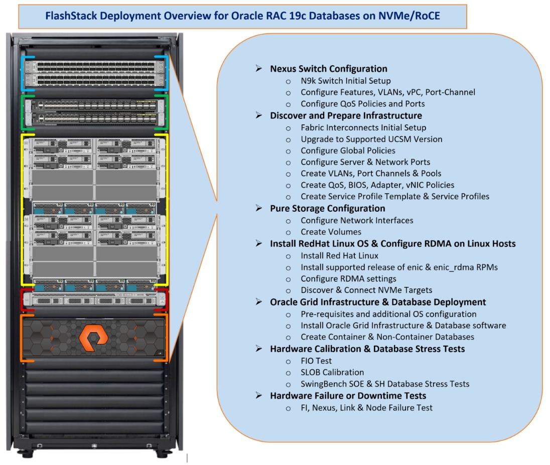
Figure 3 highlights the overview of various components such as Nexus Switches, Fabric Interconnects, Pure Storage FlashArray and Blade Servers configuration steps to deploy this reference solution.
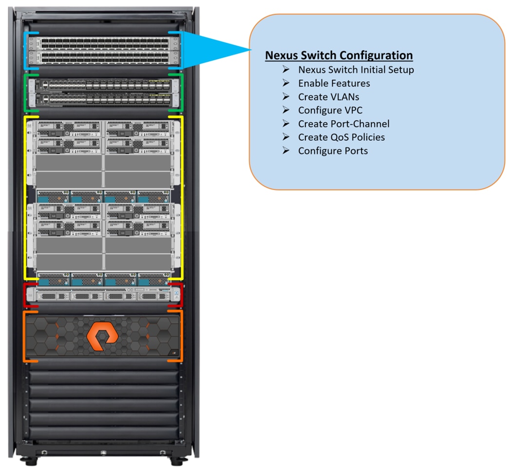
Cisco Nexus Switch Configuration
This section details the high-level steps to configure Cisco Nexus Switches as shown in Figure 4.
Initial Setup
![]() On initial boot and connection to the serial or console port of the switch, the NX-OS setup should automatically start and attempt to enter Power on Auto Provisioning.
On initial boot and connection to the serial or console port of the switch, the NX-OS setup should automatically start and attempt to enter Power on Auto Provisioning.
To set up the initial configuration for the Cisco Nexus A switch on <nexus-A-hostname>, follow these steps:
Abort Power on Auto Provisioning and continue with normal setup? (yes/no) [n]: yes
Do you want to enforce secure password standard (yes/no) [y]: Enter
Enter the password for "admin": <password>
Confirm the password for "admin": <password>
Would you like to enter the basic configuration dialog (yes/no): yes
Create another login account (yes/no) [n]: Enter
Configure read-only SNMP community string (yes/no) [n]: Enter
Configure read-write SNMP community string (yes/no) [n]: Enter
Enter the switch name: <nexus-A-hostname>
Continue with Out-of-band (mgmt0) management configuration? (yes/no) [y]: Enter
Mgmt0 IPv4 address: <nexus-A-mgmt0-ip>
Mgmt0 IPv4 netmask: <nexus-A-mgmt0-netmask>
Configure the default gateway? (yes/no) [y]: Enter
IPv4 address of the default gateway: <nexus-A-mgmt0-gw>
Configure advanced IP options? (yes/no) [n]: Enter
Enable the telnet service? (yes/no) [n]: Enter
Enable the ssh service? (yes/no) [y]: Enter
Type of ssh key you would like to generate (dsa/rsa) [rsa]: Enter
Number of rsa key bits <1024-2048> [1024]: Enter
Configure the ntp server? (yes/no) [n]: y
NTP server IPv4 address: <global-ntp-server-ip>
Configure default interface layer (L3/L2) [L3]: L2
Configure default switchport interface state (shut/noshut) [noshut]: Enter
Configure CoPP system profile (strict/moderate/lenient/dense/skip) [strict]: Enter
Would you like to edit the configuration? (yes/no) [n]: Enter
Nexus B Switch
Similarly, follow the steps from section Nexus A Switch to setup the initial configuration for the Cisco Nexus B and change the relevant switch hostname and management address.
Global Settings
To set global configuration, follow these steps on both Nexus switches.
1. Login as admin user into the Nexus Switch A and run the following commands to set global configuration on Switch A.
configure terminal
feature interface-vlan
feature hsrp
feature lacp
feature vpc
feature lldp
feature udld
spanning-tree port type edge bpduguard default
spanning-tree port type network default
port-channel load-balance src-dst l4port
policy-map type network-qos jumbo
class type network-qos class-default
mtu 9216
policy-map type network-qos RoCE-UCS-NQ-Policy
class type network-qos c-8q-nq3
pause pfc-cos 3
mtu 9216
class type network-qos c-8q-nq5
pause pfc-cos 5
mtu 9216
vrf context management
ip route 0.0.0.0/0 10.29.135.1
system qos
service-policy type network-qos RoCE-UCS-NQ-Policy
class-map type qos match-all class-pure
match dhcp 46
class-map type qos match-all class-platinum
match cos 5
class-map type qos match-all class-best-effort
match cos 0
policy-map type qos policy-pure
description qos policy for pure ports
class class-pure
set qos-group 5
set cos 5
set dscp 46
policy-map type qos system_qos_policy
description qos policy for FI to Nexus ports
class class-platinum
set qos-group 5
set dlb-disable
set dscp 46
set cos 5
class class-best-effort
set qos-group 0
copy running-config startup-config
2. Login as admin user into the Nexus Switch B and run the same commands (above) to set global configuration on Switch B.
![]() Make sure to run copy run start to save the configuration on each switch after the configuration is completed.
Make sure to run copy run start to save the configuration on each switch after the configuration is completed.
VLANs Configuration
To create the necessary virtual local area networks (VLANs), follow these steps on both the Nexus switches.
1. Log into Nexus Switch A as admin user.
2. Create VLAN 135 for Public Network Traffic, VLAN 10 for Private Network Traffic, VLAN 11 and 12 for Storage Network Traffic.
configure terminal
vlan 10
name Oracle_RAC_Private_Network
no shutdown
vlan 11
name RoCE_Traffic_FI_A
no shutdown
vlan 12
name RoCE_Traffic_FI_B
no shutdown
vlan 135
name Oracle_RAC_Public_Network
no shutdown
interface Ethernet1/31
description connect to uplink switch
switchport access vlan 135
speed 1000
copy running-config startup-config
3. Log into Nexus Switch B as admin user and create VLAN 135 for Public Network Traffic, VLAN 10 for Private Network Traffic, VLAN 11 & 12 for Storage Network Traffic.
![]() Make sure to run copy run start to save the configuration on each switch after the configuration is completed.
Make sure to run copy run start to save the configuration on each switch after the configuration is completed.
Virtual Port Channel (vPC) Summary for Network Traffic
A port channel bundles individual links into a channel group to create a single logical link that provides the aggregate bandwidth of up to eight physical links. If a member port within a port channel fails, traffic previously carried over the failed link switches to the remaining member ports within the port channel. Port channeling also load balances traffic across these physical interfaces. The port channel stays operational as long as at least one physical interface within the port channel is operational. Using port channels, Cisco NX-OS provides wider bandwidth, redundancy, and load balancing across the channels
In Cisco Nexus Switch topology, a single vPC feature is enabled to provide HA, faster convergence in the event of a failure, and greater throughput. Cisco Nexus vPC configurations with the vPC domains and corresponding vPC names and IDs for Oracle Database Servers is shown in Table 7 .
| vPC Domain |
vPC Name |
vPC ID |
| 1 |
Peer-Link |
1 |
| 1 |
vPC FI-A |
51 |
| 1 |
vPC FI-B |
52 |
As listed in Table 7 , a single vPC domain with Domain ID 1 is created across two Nexus switches to define vPC members to carry specific VLAN network traffic. In this topology, we defined a total number of 3 vPCs.
vPC ID 1 is defined as Peer link communication between the two Nexus switches. vPC IDs 51 and 52 are configured for both Cisco UCS fabric interconnects. Please follow these steps to create this configuration.
![]() A port channel bundles up to eight individual interfaces into a group to provide increased bandwidth and redundancy.
A port channel bundles up to eight individual interfaces into a group to provide increased bandwidth and redundancy.
Create vPC Peer-Link
For vPC 1 as Peer-link, we used interfaces 1 to 4 for Peer-Link. You may choose an appropriate number of ports based on your needs. To create the necessary port channels between devices, follow these steps on both Nexus Switches:
1. Log into Nexus Switch A as admin user
configure terminal
vpc domain 1
peer-keepalive destination 10.29.135.104 source 10.29.135.103
auto-recovery
interface port-channel1
description vPC peer-link
switchport mode trunk
switchport trunk allowed vlan 1,10-12,135
spanning-tree port type network
service-policy type qos input system_qos_policy
vpc peer-link
interface Ethernet1/1
description Peer link connected to N9K-B-Eth1/1
switchport mode trunk
switchport trunk allowed vlan 1,10-12,135
channel-group 1 mode active
interface Ethernet1/2
description Peer link connected to N9K-B-Eth1/2
switchport mode trunk
switchport trunk allowed vlan 1,10-12,135
channel-group 1 mode active
interface Ethernet1/3
description Peer link connected to N9K-B-Eth1/3
switchport mode trunk
switchport trunk allowed vlan 1,10-12,135
channel-group 1 mode active
interface Ethernet1/4
description Peer link connected to N9K-B-Eth1/4
switchport mode trunk
switchport trunk allowed vlan 1,10-12,135
channel-group 1 mode active
copy running-config startup-config
2. Login as admin user into the Nexus Switch B and repeat the above steps to configure second Nexus Switch. Make sure to changes the description of interfaces accordingly.
![]() Make sure to change peer-keepalive destination and source IP address appropriately for Nexus Switch A and B.
Make sure to change peer-keepalive destination and source IP address appropriately for Nexus Switch A and B.
Create vPC between Nexus Switches and Fabric Interconnects
This section describes how to create and configure port channel 51 and 52 for storage and network traffic between Nexus and Fabric Interconnect Switches.
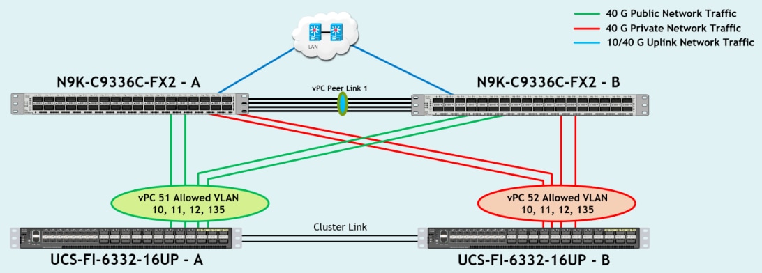
Table 8 lists the Port-Channel configured on Fabric Interconnect and Nexus Switches for this solution.
Table 8 Nexus Switch and Fabric Interconnect Switch Connectivity
| vPC Description |
vPC ID |
Fabric Interconnects Ports |
Nexus Switch Ports |
Allowed VLANs |
| Port Channel FI-A |
51 |
FI-A Port 1/31 |
N9K-A Port 1/9 |
135, 10, 11, 12
Note: VLAN 10 and 12 needed for failover |
| FI-A Port 1/32 |
N9K-A Port 1/10 |
|||
| FI-A Port 1/33 |
N9K-B Port 1/9 |
|||
| FI-A Port 1/34 |
N9K-B Port 1/10 |
|||
| Port Channel FI-B |
52 |
FI-B Port 1/31 |
N9K-A Port 1/11 |
135, 10, 11, 12
Note: VLAN 11 and 135 needed for failover |
| FI-B Port 1/32 |
N9K-A Port 1/12 |
|||
| FI-B Port 1/33 |
N9K-B Port 1/11 |
|||
| FI-B Port 1/34 |
N9K-B Port 1/12 |
To configure port channels on Nexus Switches, follow these steps:
1. Log into Nexus Switch A as admin user and run the following commands:
configure terminal
interface port-channel51
description Port-Channel FI-A
switchport mode trunk
switchport trunk allowed vlan 1,10-12,135
spanning-tree port type edge trunk
mtu 9216
service-policy type qos input system_qos_policy
vpc 51
interface port-channel52
description Port-Channel FI-B
switchport mode trunk
switchport trunk allowed vlan 1,10-12,135
spanning-tree port type edge trunk
mtu 9216
service-policy type qos input system_qos_policy
vpc 52
interface Ethernet1/9
description Connected to Fabric-Interconnect-A-31
switchport mode trunk
switchport trunk allowed vlan 1,10-12,135
spanning-tree port type edge trunk
mtu 9216
channel-group 51 mode active
interface Ethernet1/10
description Connected to Fabric-Interconnect-A-32
switchport mode trunk
switchport trunk allowed vlan 1,10-12,135
spanning-tree port type edge trunk
mtu 9216
channel-group 51 mode active
interface Ethernet1/11
description Connected to Fabric-Interconnect-B-31
switchport mode trunk
switchport trunk allowed vlan 1,10-12,135
spanning-tree port type edge trunk
mtu 9216
channel-group 52 mode active
interface Ethernet1/12
description Connected to Fabric-Interconnect-B-32
switchport mode trunk
switchport trunk allowed vlan 1,10-12,135
spanning-tree port type edge trunk
mtu 9216
channel-group 52 mode active
copy running-config startup-config
2. Login as admin user into the Nexus Switch B and repeat the above steps to configure second Nexus Switch:
configure terminal
interface port-channel51
description Port-Channel FI-A
switchport mode trunk
switchport trunk allowed vlan 1,10-12,135
spanning-tree port type edge trunk
mtu 9216
service-policy type qos input system_qos_policy
vpc 51
interface port-channel52
description Port-Channel FI-B
switchport mode trunk
switchport trunk allowed vlan 1,10-12,135
spanning-tree port type edge trunk
mtu 9216
service-policy type qos input system_qos_policy
vpc 52
interface Ethernet1/9
description Connected to Fabric-Interconnect-A-33
switchport mode trunk
switchport trunk allowed vlan 1,10-12,135
spanning-tree port type edge trunk
mtu 9216
channel-group 51 mode active
interface Ethernet1/10
description Connected to Fabric-Interconnect-A-34
switchport mode trunk
switchport trunk allowed vlan 1,10-12,135
spanning-tree port type edge trunk
mtu 9216
channel-group 51 mode active
interface Ethernet1/11
description Connected to Fabric-Interconnect-B-33
switchport mode trunk
switchport trunk allowed vlan 1,10-12,135
spanning-tree port type edge trunk
mtu 9216
channel-group 52 mode active
interface Ethernet1/12
description Connected to Fabric-Interconnect-B-34
switchport mode trunk
switchport trunk allowed vlan 1,10-12,135
spanning-tree port type edge trunk
mtu 9216
channel-group 52 mode active
copy running-config startup-config
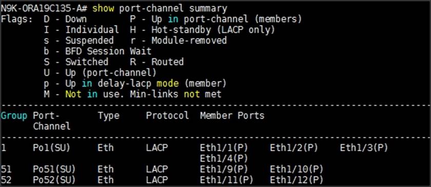
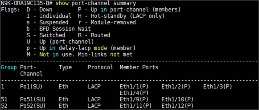
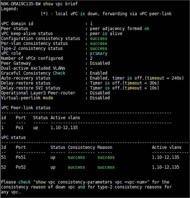
Verify all vPC Status
To verify all vPC status, follow these steps:
1. Log into Nexus Switches as admin user and run the following commands to verify the port channel summary.

Configure Nexus Switch to Storage Ports
This section details how to configure Nexus switches to storage ports.

Table 9 lists the port connectivity between the Nexus Switches and Pure Storage FlashArray//X90 R2.
Table 9 Storage and Nexus Switch Connectivity
| Nexus Ports |
Pure Storage Ports |
Allowed VLANs |
Pure Storage Interface IP Configured |
| N9K-A Port 1/23 |
Storage Controller CT0.Eth14 |
11 |
200.200.11.3 |
| N9K-A Port 1/24 |
Storage Controller CT1.Eth14 |
12 |
200.200.12.4 |
| N9K-B Port 1/23 |
Storage Controller CT0.Eth15 |
12 |
200.200.12.3 |
| N9K-B Port 1/24 |
Storage Controller CT1.Eth15 |
11 |
200.200.11.4 |
To configure storage ports on Nexus Switches, follow these steps:
1. Log into Nexus Switch A as admin user and run the following commands:
configure terminal
interface Ethernet1/23
description Connected to Pure-Storage-CT0.Eth14
switchport access vlan 11
priority-flow-control mode on
spanning-tree port type edge
mtu 9216
service-policy type qos input policy-pure
interface Ethernet1/24
description Connected to Pure-Storage-CT1.Eth14
switchport access vlan 12
priority-flow-control mode on
spanning-tree port type edge
mtu 9216
service-policy type qos input policy-pure
copy running-config startup-config
2. Login as admin user into the Nexus Switch B and repeat the above steps to configure second Nexus Switch.
configure terminal
interface Ethernet1/23
description Connected to Pure-Storage-CT0.Eth15
switchport access vlan 12
priority-flow-control mode on
spanning-tree port type edge
mtu 9216
service-policy type qos input policy-pure
interface Ethernet1/24
description Connected to Pure-Storage-CT1.Eth15
switchport access vlan 11
priority-flow-control mode on
spanning-tree port type edge
mtu 9216
service-policy type qos input policy-pure
copy running-config startup-config
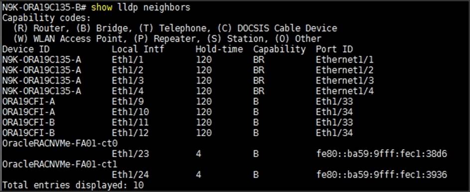
3. Verify all Nexus Switches connectivity as shown below:

Configure Pure Storage FlashArray//X90 R2
This section describes the high-level steps to configure Pure Storage FlashArray//X90 R2 used in this solution.
For this solution, Pure Storage FlashArray was loaded with Purity//FA Version 5.3.2, which supports NVMe/RoCE. Alternatively, you can go for newer Purity//FA Version 5.3.5 which is recommended by Pure Storage.
Pure storage support needs to configure NVMe/RoCE services on the FlashArray. The hosts were redundantly connected to the storage controllers through 4 x 100Gb connections (2 x 100Gb per storage controller module) from the redundant Cisco Nexus 9K switches.
The FlashArray network settings were configured with three subnets across three VLANs. Storage Interfaces CT0.Eth0 and CT1.Eth0 were configured to access management for the storage on VLAN 135. Storage Interfaces (CT0.Eth14, CT0.Eth15, CT1.Eth14 & CT1.Eth15) were configured to run RoCE Storage network traffic on the VLAN 11 and VLAN 12 to access database storage from all the oracle RAC nodes.
To configure network settings into Pure Storage FlashArray, follow these steps:
1. Open a web browser and navigate to the Pure Storage FlashArray//X90 R2 Cluster address.
2. Enter the Username and Password for the storage.
3. From the Pure Storage Dashboard, go to Settings > Network. Click Edit Interface.
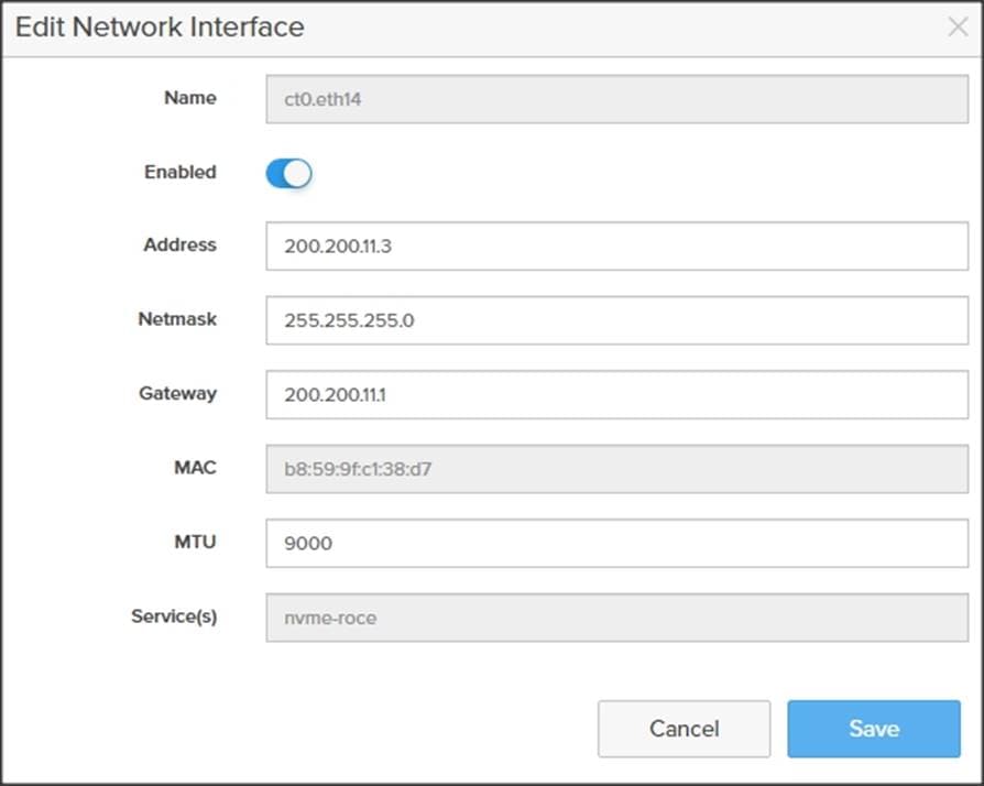
4. Enter Address, Netmask, Gateway and MTU as shown above and click Save to configure the interface.
The configured network interfaces are shown below:
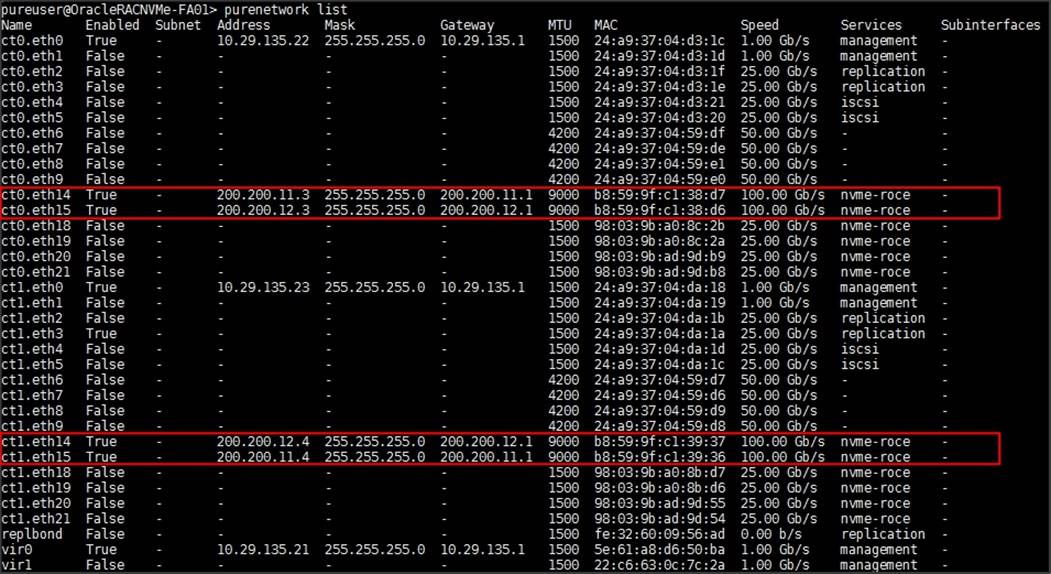
For this solution, you will use these interface addresses and configure RoCE network traffic to run Oracle RAC databases. You will also configure Volumes, Hosts and Host Groups as discussed in the following sections when you are ready to deploy Oracle RAC Database software.
Cisco UCS Configuration
This section details the Cisco UCS configuration that was done as part of the infrastructure buildout. The racking, power, and installation of the chassis are described in the installation guide ( See https://www.cisco.com/c/en/us/support/servers-unified-computing/ucs-manager/products-installation-guides-list.html). It is beyond the scope of this document to explain the Cisco UCS infrastructure setup and connectivity. The documentation guides and examples are available here: https://www.cisco.com/c/en/us/support/servers-unified-computing/ucs-manager/products-installation-and-configuration-guides-list.html.

![]() This document details all the tasks to configure Cisco UCS but only some screenshots are included.
This document details all the tasks to configure Cisco UCS but only some screenshots are included.
Using logical servers that are disassociated from the physical hardware removes many limiting constraints around how servers are provisioned. Cisco UCS Service Profiles contain values for a server's property settings, including virtual network interface cards (vNICs), MAC addresses, boot policies, firmware policies, fabric connectivity, external management, and HA information. The service profiles represent all the attributes of a logical server in Cisco UCS model. By abstracting these settings from the physical server into a Cisco Service Profile, the Service Profile can then be deployed to any physical compute hardware within the Cisco UCS domain. Furthermore, Service Profiles can, at any time, be migrated from one physical server to another. Furthermore, Cisco is the only hardware provider to offer a truly unified management platform, with Cisco UCS Service Profiles and hardware abstraction capabilities extending to both blade and rack servers.
The following are the high-level steps involved for a Cisco UCS configuration:
1. Perform Initial Setup of Fabric Interconnects for a Cluster Setup.
2. Upgrade UCS Manager Software to Version 4.1.1a
3. Synchronize Cisco UCS to NTP.
4. Configure Fabric Interconnects for Chassis and Blade Discovery:
a. Configure Global Policies
b. Configure Server Ports
5. Configure LAN:
a. Configure Ethernet LAN Uplink Ports
b. Create Uplink Port Channels to Nexus Switches
c. Configure VLANs
6. Configure IP, UUID, Server and MAC Pools:
a. IP Pool Creation
b. UUID Suffix Pool Creation
c. Server Pool Creation
d. MAC Pool Creation
7. Set Jumbo Frames in both the Fabric Interconnect.
8. Create QoS Policy for RoCE.
9. Configure Server BIOS Policy.
10. Create Adapter Policy:
a. Create Adapter Policy for Public and Private Network Interfaces
b. Create Adapter Policy for Storage Network RoCE Interfaces
11. Configure Update Default Maintenance Policy.
12. Configure vNIC Template:
a. Create Public vNIC Template
b. Create Private vNIC Template
c. Create Storage vNIC Template
13. Create Server Boot Policy for Local Boot.
The details for each step are provided in the following sections.
Perform Initial Setup of Fabric Interconnects for a Cluster Setup
This section provides detailed procedures for configuring the Cisco Unified Computing System (Cisco UCS) for use in a FlashStack environment. The steps are necessary to provision the Cisco UCS B-Series and C-Series servers and should be followed precisely to avoid improper configuration.
Configure Fabric Interconnect A and Fabric Interconnect B
To configure the UCS Fabric Interconnects, follow these steps.
1. Verify the following physical connections on the fabric interconnect:
a. The management Ethernet port (mgmt0) is connected to an external hub, switch, or router
b. The L1 ports on both fabric interconnects are directly connected to each other
c. The L2 ports on both fabric interconnects are directly connected to each other
2. Connect to the console port on the first Fabric Interconnect.
3. Review the settings printed to the console. Answer yes to apply and save the configuration.
4. Wait for the login prompt to make the configuration has been saved to Fabric Interconnect A.
5. Now, connect console port on the second Fabric Interconnect and do as following
6. Review the settings printed to the console. Answer yes to apply and save the configuration.
7. Wait for the login prompt to make the configuration has been saved to Fabric Interconnect B
Log into Cisco UCS Manager
To log into the Cisco Unified Computing System (Cisco UCS) environment, follow these steps:
1. Open a web browser and navigate to the Cisco UCS fabric interconnect cluster address.
![]() You may need to wait at least 5 minutes after configuring the second fabric interconnect for Cisco UCS Manager to come up.
You may need to wait at least 5 minutes after configuring the second fabric interconnect for Cisco UCS Manager to come up.
2. Click the Launch UCS Manager link under HTML to launch Cisco UCS Manager.
3. If prompted to accept security certificates, accept as necessary.
4. When prompted, enter admin as the username and enter the administrative password.
5. Click Login to log into Cisco UCS Manager.
Configure Cisco UCS Call Home
It is highly recommended by Cisco to configure Call Home in Cisco UCS Manager. Configuring Call Home will accelerate the resolution of support cases. To configure Call Home, follow these steps:
1. In Cisco UCS Manager, click Admin.
2. Select All > Communication Management > Call Home.
3. Change the State to On.
4. Fill in all the fields according to your Management preferences and click Save Changes and click OK to complete configuring Call Home
Upgrade Cisco UCS Manager Software to Version 4.1
This solution was configured on Cisco UCS 4.1 software release. To upgrade the Cisco UCS Manager software and the Cisco UCS Fabric Interconnect software to version 4.1, go to https://www.cisco.com/c/en/us/support/servers-unified-computing/ucs-manager/products-installation-guides-list.html
Synchronize Cisco UCS Manager to NTP
To synchronize the Cisco UCS Manager environment to the NTP server, follow these steps:
1. In Cisco UCS Manager, in the navigation pane, click the Admin tab.
2. Select All > Time zone Management.
3. In the Properties pane, select the appropriate time zone in the Time zone menu.
4. Click Save Changes and then click OK.
5. Click Add NTP Server.
6. Enter the NTP server IP address and click OK.
7. Click OK to finish
Configure Fabric Interconnect for Chassis and Blade Discovery
Cisco UCS 6332-16UP Fabric Interconnects are configured for redundancy. It provides resiliency in case of failures. The first step to establish connectivity between blade servers and Fabric Interconnects.
Configure Global Policies
The chassis discovery policy determines how the system reacts when you add a new chassis. We recommend using the platform max value as shown. Using platform max helps ensure that Cisco UCS Manager uses the maximum number of IOM uplinks available.
To configure global policies, follow these steps:
1. Go to Equipment > Policies (right pane) > Global Policies > Chassis/FEX Discovery Policies. As shown in the screenshot below, select Action as Platform Max from the drop-down list and set Link Grouping to Port Channel.
2. Click Save Changes.
3. Click OK.
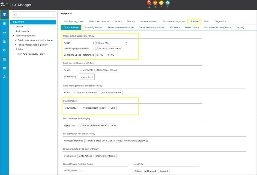
The difference between Discrete mode vs Port Channel mode is shown below:

Configure Server Ports
To configure server ports to initiate chasses and blade recovery, follow these steps:
1. Go to Equipment > Fabric Interconnects > Fabric Interconnect A > Fixed Module > Ethernet Ports.
2. Select the ports (for this solution ports are 17-24) which are connected to the Cisco IO Modules of the two Cisco UCS B-Series 5108 Chassis.
3. Right-click and select Configure as Server Port.
4. Click Yes to confirm and click OK.
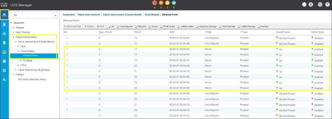
5. Repeat steps 1-4 for Fabric Interconnect B.
6. After configuring Server Ports, acknowledge both the Chassis. Go to Equipment > Chassis > Chassis 1 > General > Actions > select Acknowledge Chassis. Similarly, acknowledge the chassis 2.
7. After acknowledging both the chassis, Re-acknowledge all the servers placed in the chassis. Go to Equipment > Chassis 1 > Servers > Server 1 > General > Actions > select Server Maintenance > select option Re-acknowledge and click OK. Similarly, repeat the process to Re-acknowledge all the eight Servers.
8. Once the acknowledgement of the Servers completed, verify Port-channel of Internal LAN. Go to tab LAN > Internal LAN > Internal Fabric A > Port Channels as shown below.

9. Verify the same for Internal Fabric B.
![]() The last 6 ports of the Cisco UCS 6332 and Cisco UCS 6332-16UP FIs will only work with optical based QSFP transceivers and AOC cables, so they can be better utilized as uplinks to upstream resources that might be optical only.
The last 6 ports of the Cisco UCS 6332 and Cisco UCS 6332-16UP FIs will only work with optical based QSFP transceivers and AOC cables, so they can be better utilized as uplinks to upstream resources that might be optical only.
Configure LAN
Configure Ethernet Uplink ports as explained in the following sections.
Configure Ethernet LAN Uplinks Ports
To configure network ports used to uplink the Fabric Interconnects to the Nexus switches, follow these steps:
1. In Cisco UCS Manager, in the navigation pane, click the Equipment tab.
2. Select Equipment > Fabric Interconnects > Fabric Interconnect A > Fixed Module.
3. Expand Ethernet Ports.
4. Select ports (for this solution ports are 31-34) that are connected to the Nexus switches, right-click them, and select Configure as Network Port.
5. Click Yes to confirm ports and click OK.
6. Verify the Ports connected to Nexus upstream switches are now configured as network ports.
7. Repeat steps 1-6 for Fabric Interconnect B. The screenshot shows the network uplink ports for Fabric A.
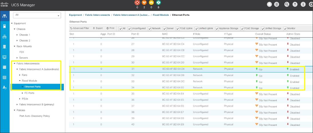
Now you have created four uplink ports on each Fabric Interconnect as shown above. These ports will be used to create Virtual Port Channel in the next section.
![]() The last 6 ports of the Cisco UCS 6332 and UCS 6332-16UP FIs will only work with optical based QSFP transceivers and AOC cables, so they can be better utilized as uplinks to upstream resources that might be optical only.
The last 6 ports of the Cisco UCS 6332 and UCS 6332-16UP FIs will only work with optical based QSFP transceivers and AOC cables, so they can be better utilized as uplinks to upstream resources that might be optical only.
Create Uplink Port Channels to Nexus Switches
In this procedure, two port channels were created: one from Fabric A to both Nexus switch and one from Fabric B to both Nexus switch. To configure the necessary port channels in the Cisco UCS environment, follow these steps:
1. In Cisco UCS Manager, click the LAN tab in the navigation pane.
2. Under LAN > LAN Cloud, expand node Fabric A tree:
a. Right-click Port Channels.
b. Select Create Port Channel.
c. Enter 51 as the unique ID of the port channel.
d. Enter FI-A as the name of the port channel.

e. Click Next.
f. Select Ethernet ports 31-34 for the port channel.
g. Click >> to add the ports to the port channel
3. Click Finish to create the port channel and then click OK.
4. Repeat steps 1-3 for Fabric Interconnect B, substituting 52 for the port channel number and FI-B for the name. The resulting configuration should look like the screenshot shown below.

Configure VLANs
In this solution, four VLANs were created: one for private network (VLAN 10) traffic, one for public network (VLAN 135) traffic and two storage network (VLAN 11 and VLAN 12) traffic. These four VLANs will be used in the vNIC templates that are discussed later.
To configure the necessary virtual local area networks (VLANs) for the Cisco UCS environment, follow these steps:
![]() It is very important to create both VLANs as global across both fabric interconnects. This way, VLAN identity is maintained across the fabric interconnects in case of NIC failover.
It is very important to create both VLANs as global across both fabric interconnects. This way, VLAN identity is maintained across the fabric interconnects in case of NIC failover.
1. In Cisco UCS Manager, click the LAN tab in the navigation pane.
2. Select LAN > LAN Cloud.
3. Right-click VLANs.
4. Select Create VLANs.

5. Enter Public_Traffic as the name of the VLAN to be used for Public Network Traffic.
6. Keep the Common/Global option selected for the scope of the VLAN.
7. Enter 135 as the ID of the VLAN ID.
8. Keep the Sharing Type as None.
9. Click OK and then click OK again.
10. Create the second VLAN: for private network (VLAN 10) traffic and remaining two storage VLANs for storage network (VALN 11 & 12) traffic as shown below:
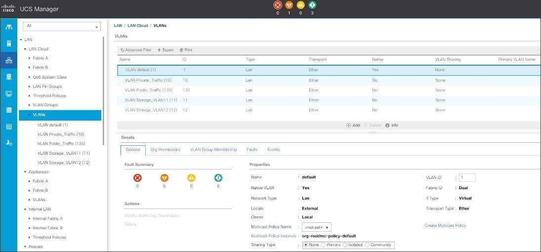
These four VLANs will be used in the vNIC templates that are discussed.
Configure IP, UUID, Server and MAC Pools
IP Pool Creation
An IP address pool on the out of band management network must be created to facilitate KVM access to each compute node in the UCS domain. To create a block of IP addresses for server KVM access in the Cisco UCS environment, follow these steps:
1. In Cisco UCS Manager, in the navigation pane, click the LAN tab.
2. Select Pools > root > IP Pools >click Create IP Pool.
3. We have named IP Pool as ORA19C-KVMPoo for this solution.
4. Select option Sequential to assign IP in sequential order then click next.
5. Click Add IPv4 Block.
6. Enter the starting IP address of the block and the number of IP addresses required, and the subnet and gateway information as shown below.

7. Click Next and Finish to create the IP block.
UUID Suffix Pool Creation
To configure the necessary universally unique identifier (UUID) suffix pool for the Cisco UCS environment, follow these steps:
1. In Cisco UCS Manager, click the Servers tab in the navigation pane.
2. Select Pools > root.
3. Right-click UUID Suffix Pools and then select Create UUID Suffix Pool.
4. Enter ORA19C-UUID-Pool as the name of the UUID name.
5. Optional: Enter a description for the UUID pool.
6. Keep the prefix at the derived option and select Sequential in as Assignment Order then click Next.
7. Click Add to add a block of UUIDs.
8. Create a starting point UUID as per your environment.
9. Specify a size for the UUID block that is sufficient to support the available blade or server resources.
Server Pool Creation
To configure the necessary server pool for the Cisco UCS environment, follow these steps:
![]() Consider creating unique server pools to achieve the granularity that is required in your environment.
Consider creating unique server pools to achieve the granularity that is required in your environment.
1. In Cisco UCS Manager, click the Servers tab in the navigation pane.
2. Select Pools > root > Right-click Server Pools > Select Create Server Pool.
3. Enter ORA19C-SERVER-POOL as the name of the server pool.
4. Optional: Enter a description for the server pool then click Next.
5. Select all the eight servers to be used for the Oracle RAC management and click > to add them to the server pool.
6. Click Finish and click OK.
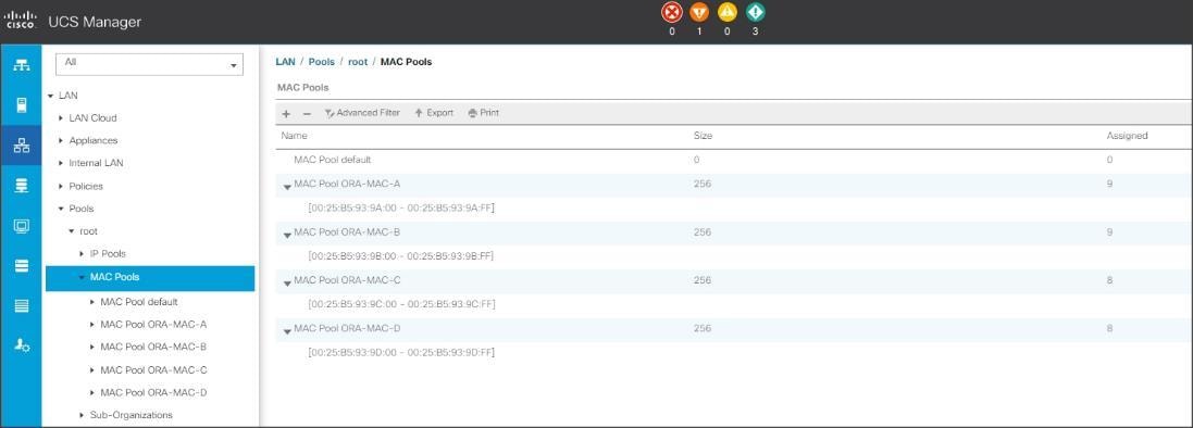
MAC Pool Creation
To configure the necessary MAC address pools for the Cisco UCS environment, follow these steps:
1. In Cisco UCS Manager, click the LAN tab in the navigation pane.
2. Select Pools > root > right-click MAC Pools under the root organization.
3. Select Create MAC Pool to create the MAC address pool.
4. Enter ORA-MAC-A as the name for MAC pool.
5. Enter the seed MAC address and provide the number of MAC addresses to be provisioned.
6. Click OK and then click Finish.
7. In the confirmation message, click OK.
8. Create remaining MAC Pool and assign unique MAC Addresses as shown below:
![]() When there are multiple Cisco UCS domains sitting in adjacency, it is important that these blocks of MAC Addresses, hold differing values between each set.
When there are multiple Cisco UCS domains sitting in adjacency, it is important that these blocks of MAC Addresses, hold differing values between each set.
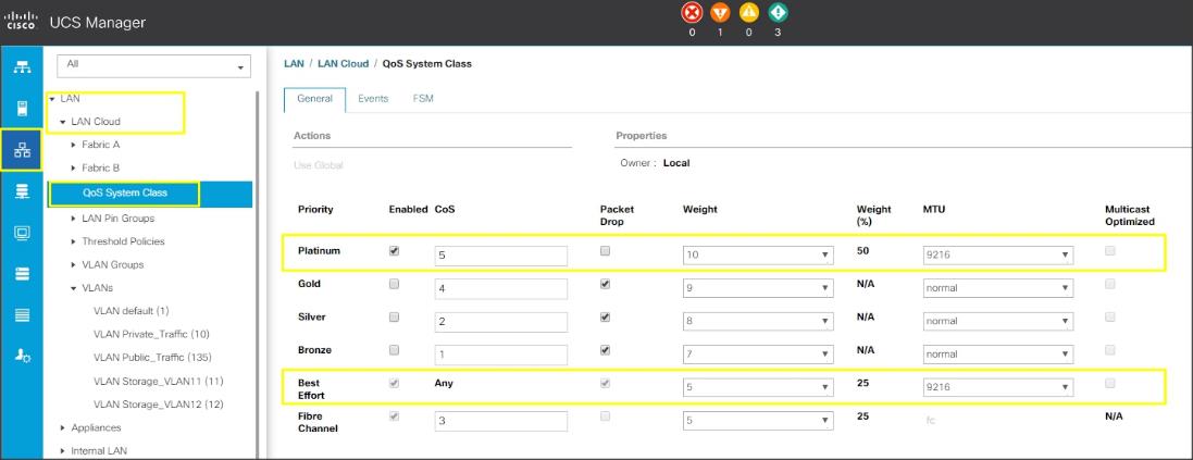
Set Jumbo Frames in both the Fabric Interconnect
To configure jumbo frames and enable quality of service in the Cisco UCS fabric, follow these steps:
1. In Cisco UCS Manager, click the LAN tab in the navigation pane.
2. Select LAN > LAN Cloud > QoS System Class.
3. In the right pane, click the General tab.
4. On the Best Effort row, enter 9216 in the box under the MTU column.
5. Enable the Platinum Priority and configured as shown below.
6. Click Save Changes in the bottom of the window.
7. Click OK.
The Platinum QoS System Classes are enabled in this FlashStack implementation. The Cisco UCS and Nexus switches are intentionally configured this way so that all IP traffic within the FlashStack will be treated as Platinum CoS5. Enabling the other QoS System Classes without having a comprehensive, end-to-end QoS setup in place can cause difficult to troubleshoot issues.
For example, Pure storage controllers by default mark all interfaces nvme-roce protocol packets with a CoS value of 5. With the configuration on the Nexus switches in this implementation, storage packets will pass through the switches and into the UCS Fabric Interconnects with CoS 5 set in the packet header.
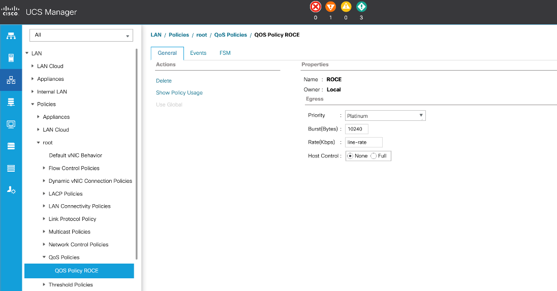
Create QoS Policy for RoCE
To configure QoS Policy for RoCE Network traffic, follow these steps:
1. Go to LAN > Policies > root > QoS Policies and right-click for Create QoS Policy
2. Name the policy as ROCE and select priority as Platinum as shown below:
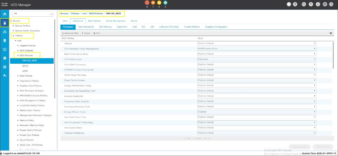
Configure Server BIOS Policy
To create a server BIOS policy for the Cisco UCS environment, follow these steps
1. In Cisco UCS Manager, click Servers.
2. Select Policies > root.
3. Right-click BIOS Policies.
4. Select Create BIOS Policy.
5. Enter ORA19C_BIOS as the BIOS policy name
6. Select and click the newly created BIOS Policy.
7. Click the Advanced tab, leaving the Processor tab selected within the Advanced tab.
8. Set the following within the Processor tab:
- CPU Hardware Power Management: HWPM Native Mode
- CPU Performance: Enterprise
- Energy Efficient Turbo: Disabled
- IMC Inteleave: Auto
- Sub NUMA Clustering: Disabled
- Package C State Limit: C0 C1 State
- Processor C State: Disabled
- Processor C1E: Disabled
- Processor C3 Report: Disabled
- Processor C6 Report: Disabled
- Processor C7 Report: Disabled
- LLC Prefetch: Disabled
- Demand Scrub: Disabled
- Patrol Scrub: Disabled
- Workload Configuration: IO Sensitive

9. Set the following within the RAS Memory tab:
- Memory RAS configuration: ADDDC Sparing
10. Click Save Changes and then click OK.
![]() All BIOS policies might be required on your setup. Please follow the steps according to your environment and requirement. The following changes were made on the test bed where Oracle RAC installed. Please validate and change as needed.
All BIOS policies might be required on your setup. Please follow the steps according to your environment and requirement. The following changes were made on the test bed where Oracle RAC installed. Please validate and change as needed.
![]() For more details on BIOS settings, refer to: https://www.cisco.com/c/dam/en/us/products/collateral/servers-unified-computing/ucs-b-series-blade-servers/whitepaper_c11-740098.pdf
For more details on BIOS settings, refer to: https://www.cisco.com/c/dam/en/us/products/collateral/servers-unified-computing/ucs-b-series-blade-servers/whitepaper_c11-740098.pdf
![]() It is recommended to disable C states in the BIOS and in addition, Oracle recommends disabling it from OS level as well by modifying grub entries. The OS level settings are explained in section Operating System Configuration.
It is recommended to disable C states in the BIOS and in addition, Oracle recommends disabling it from OS level as well by modifying grub entries. The OS level settings are explained in section Operating System Configuration.
Create Adapter Policy
In this solution, we created two adapter policy. One Adapter policy for Public and Private Network Interface Traffic and second adapter policy for Storage Network Interface RoCE Traffic as explained in the following sections.
Create Adapter Policy for Public and Private Network Interfaces
To create an Adapter Policy for the UCS environment, follow these steps:
1. In Cisco UCS Manager, click the Servers tab in the navigation pane.
2. Select Policies > root > right-click Adapter Policies.
3. Select Create Ethernet Adapter Policy.
4. Provide a name for the Ethernet adapter policy as ORA_Linux_Tuning. Change the following fields and click Save Changes:
a. Resources
i. Transmit Queues: 8
ii. Ring Size: 4096
iii. Receive Queues: 8
iv. Ring Size: 4096
v. Completion Queues: 16
vi. Interrupts: 32
b. Options
i. Receive Side Scaling (RSS): Enabled
5. Configure the adapter policy as shown below:

![]() RSS distributes network receive processing across multiple CPUs in multiprocessor systems. This can be one of the following:
RSS distributes network receive processing across multiple CPUs in multiprocessor systems. This can be one of the following:
Disabled—Network receive processing is always handled by a single processor even if additional processors are available.
Enabled—Network receive processing is shared across processors whenever possible.
Create Adapter Policy for Storage Network RoCE Interfaces
To create an adapter policy for the storage network RoCE traffic, follow these steps:
1. In Cisco UCS Manager, click the Servers tab in the navigation pane.
2. Select Policies > root > right-click Adapter Policies.
3. Select Create Ethernet Adapter Policy.
4. Provide a name for the Ethernet adapter policy as ROCE Adapter. Change the following fields and click Save Changes when you are finished:
a. Resources
i. Transmit Queues: 8
ii. Ring Size: 4096
iii. Receive Queues: 8
iv. Ring Size: 4096
v. Completion Queues: 16
vi. Interrupts: 256
b. Options
i. Receive Side Scaling (RSS): Enabled
ii. RoCE: Enabled
iii. RoCE Properties:
- Version 2: Enabled
- Queue Pairs: 1024
- Memory Regions: 131072
- Resource Groups: 8
- Priority: Platinum
5. Configure the adapter policy as shown below:

Configure Update Default Maintenance Policy
To update the default Maintenance Policy, follow these steps:
1. In Cisco UCS Manager, click the Servers tab in the navigation pane.
2. Select Policies > root > Maintenance Policies > Default.
3. Change the Reboot Policy to User Ack.
4. Click Save Changes.
5. Click OK to accept the changes.
Configure vNIC Template
With the four vNIC template for Public Network, Private Network and RoCE Storage Network Traffic you’ve created, you will use these vNIC Templates during the creation of the Service Profile later in this section.
To create vNIC (virtual network interface card) template for the Cisco UCS environment, follow these steps:
1. In Cisco UCS Manager, click the LAN tab in the navigation pane.
2. Select Policies > root > vNIC Templates > right-click to vNIC Template and Select "Create vNIC Template."
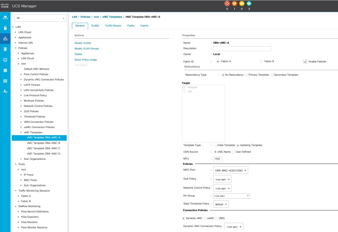
3. Enter ORA-vNIC-A as the vNIC template name and keep Fabric A selected.
4. Select the Enable Failover checkbox for high availability of the vNIC.
![]() Selecting Hardware level Failover is strongly recommended for Oracle Private Interconnect Network Interfaces.
Selecting Hardware level Failover is strongly recommended for Oracle Private Interconnect Network Interfaces.
5. Select Template Type as Updating Template.
6. Under VLANs, select the checkboxes default and Public_Traffic and set Native-VLAN as the Public_Traffic.
7. Keep MTU value 1500 for Public Network Traffic.
8. In the MAC Pool list, select ORA-MAC-A.
9. Click OK to create the vNIC template as shown below.
10. Click OK to finish.
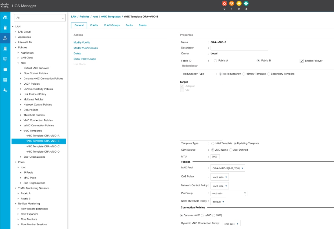
11. Similarly, create another vNIC template for Private Network Traffic with few changes.
12. Enter ORA-vNIC-B as the vNIC template name for Private Network Traffic.
13. Select the Fabric B and Enable Failover for Fabric ID options.
14. Select Template Type as Updating Template.
15. Under VLANs, select the checkboxes default and Private_Traffic and set Native-VLAN as the Private_Traffic.
16. Set MTU value to 9000 and MAC Pool as ORA-MAC-B.
17. Click OK to create the vNIC template as shown below:
18. Create third vNIC template for Storage Network Traffic through Fabric Interconnect – A.
19. Enter ORA-vNIC-C as the vNIC template name for Storage Network Traffic.
20. Select the Fabric A for Fabric ID options.
21. Select Template Type as Updating Template.
22. Under VLANs, select the checkboxes Storage_VLAN11 and set Native-VLAN as VLAN 11.
23. Set MTU value to 9000 and MAC Pool as ORA-MAC-C.
24. Set QoS Policy as ROCE.
25. Click OK to create the vNIC template as shown below.
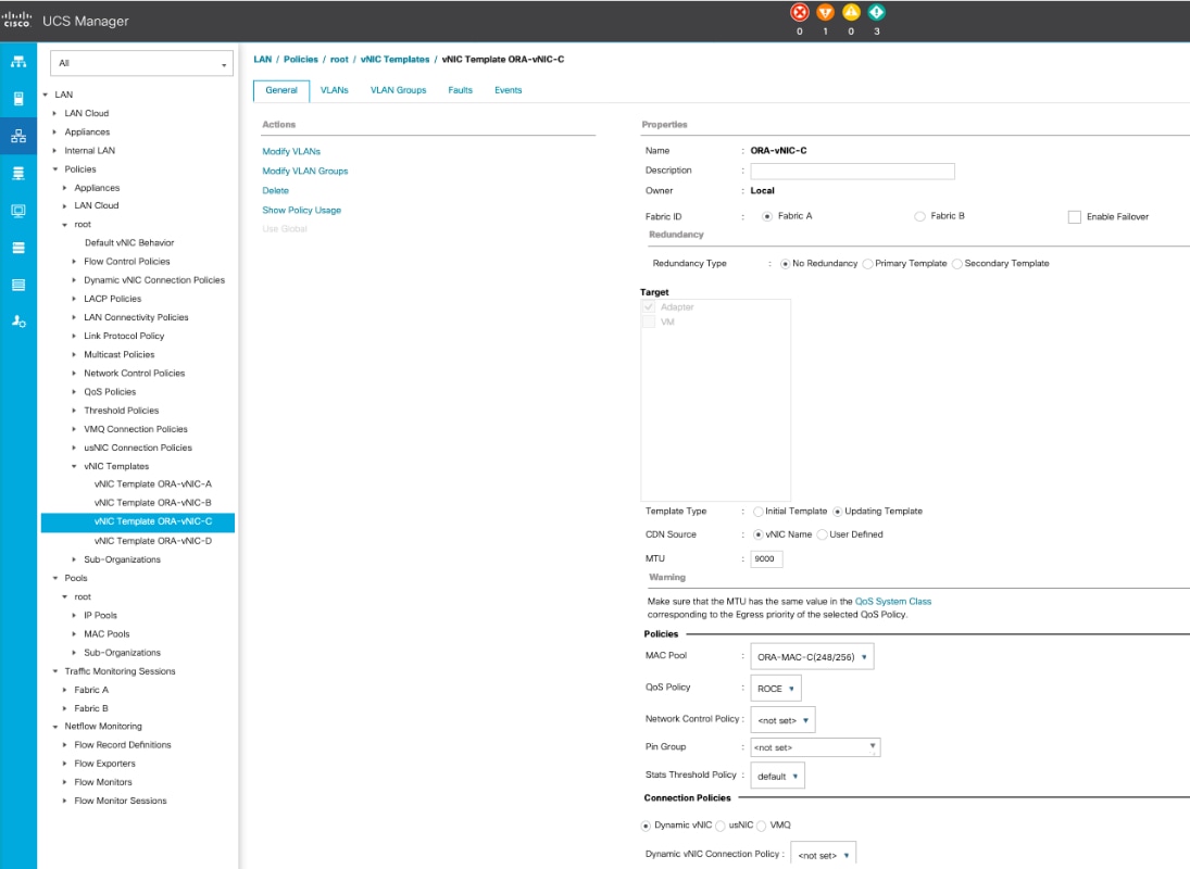
![]() Fabric failover is not supported on RoCE based vNICs with this release of UCSM and the recommendation is to use the OS level multipathing to reroute and balance the storage network traffic.
Fabric failover is not supported on RoCE based vNICs with this release of UCSM and the recommendation is to use the OS level multipathing to reroute and balance the storage network traffic.
26. Create fourth vNIC template for Storage Network Traffic through Fabric Interconnect – B.
27. Enter ORA-vNIC-D as the vNIC template name for Storage Network Traffic.
28. Select the Fabric B for Fabric ID options.
29. Select Template Type as Updating Template.
30. Under VLANs, select the checkboxes Storage_VLAN12 and set Native-VLAN as VLAN 12.
31. Set MTU value to 9000 and MAC Pool as ORA-MAC-D.
32. Set QoS Policy as ROCE.
33. Click OK to create the vNIC template as shown below.

![]() Fabric failover is not supported on RoCE based vNICs with this release of UCSM and the recommendation is to use the OS level multipathing to reroute and balance the storage network traffic.
Fabric failover is not supported on RoCE based vNICs with this release of UCSM and the recommendation is to use the OS level multipathing to reroute and balance the storage network traffic.
All the vNIC templates are configured as shown below:

Create Server Boot Policy for Local Boot
All Oracle nodes were set to boot from Local Disk for this Cisco Validated Design as part of the Service Profile template. A Local disk configuration for Cisco UCS is necessary if the servers in the environments have a local disk.
To create Boot Policies for the Cisco UCS environments, follow these steps:
1. Go to Cisco UCS Manager and then go to Servers > Policies > root > Boot Policies.
2. Right-click and select Create Boot Policy. Enter Local_Disk for the name of the boot policy.
3. Expand the Local Devices drop-down menu and Choose Add CD/DVD and then Local Disk for the Boot Order as shown below:

4. Click OK to create the boot policy.
Create and Configure Service Profile Template
Service profile templates enable policy-based server management that helps ensure consistent server resource provisioning suitable to meet predefined workload needs.
The Cisco UCS service profile provides the following benefits:
· Scalability - Rapid deployment of new servers to the environment in a very few steps.
· Manageability - Enables seamless hardware maintenance and upgrades without any restrictions.
· Flexibility - Easy to repurpose physical servers for different applications and services as needed.
· Availability - Hardware failures are not impactful and critical. In rare case of a server failure, it is easier to associate the logical service profile to another healthy physical server to reduce the impact.
You will create one Service Profile Template named ORA19C as explained in the follow sections.
Create Service Profile Template
To create a service profile template, follow these steps:
1. In the Cisco UCS Manager, go to Servers > Service Profile Templates > root and right-click to Create Service Profile Template as shown below:
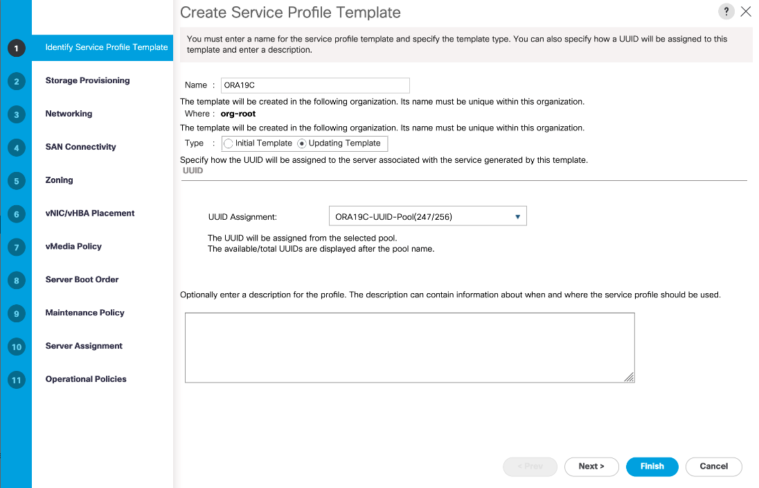
2. Enter the Service Profile Template name, select the UUID Pool that was created earlier, and click Next.
3. Select Local Disk Configuration Policy to default as Any configuration mode.
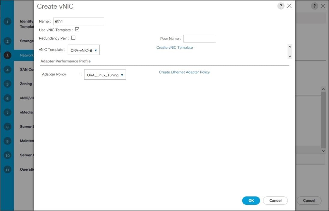
4. In the networking window, select Expert and click Add to create vNICs. Add one or more vNICs that the server should use to connect to the LAN.
Now there are four vNIC in the create vNIC menu. You have provided a name to the first vNIC as eth0 and second vNIC as eth1. Similarly, you have provided name to third vNIC as eth2 and fourth vNIC as eth3.
5. As shown below, select vNIC Template as ORA-vNIC-A and Adapter Policy as ORA_Linux_Tuning which was created earlier for vNIC eth0.

6. Select vNIC Template as Oracle-vNIC-B and Adapter Policy as ORA_Linux_Tuning for vNIC eth1.
7. For vNIC eth2, select vNIC Template as ORA-vNIC-C and Adapter Policy as ROCE_Adapter as shown below.
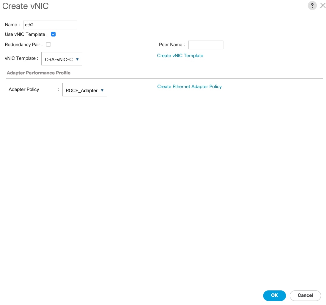
8. For vNIC eth3, select vNIC Template as ORA-vNIC-D and Adapter Policy as ROCE_Adapter as shown below.

Four vNICs are configured for each linux host as shown below:
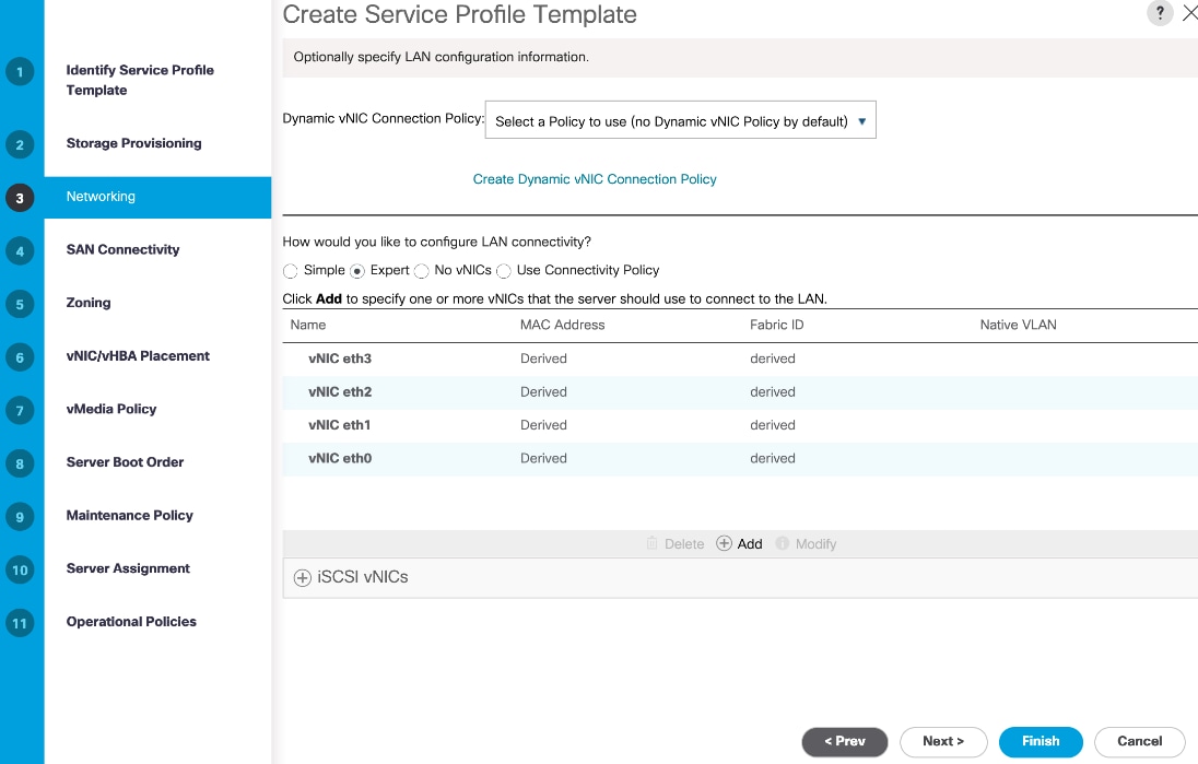
![]() With this release of UCSM, only two RDMA vNICs are supported.
With this release of UCSM, only two RDMA vNICs are supported.
9. When the vNICs are created, click Next.
10. In the SAN Connectivity menu, select No vHBAs. Click Next.
11. Skip zoning; for this Oracle RAC Configuration, we have not used any zoning for SAN.
12. In the vNIC/vHBA Placement Menu, select option Specify Manually. For this solution, we configured the vNIC placement manually as shown below:

![]() You can configure vNIC Placement by selecting option as Specify Manually. Click vCon1 from Name option and eth0 from vNICs, and then select assign button to send eth0 under vCon1 option.
You can configure vNIC Placement by selecting option as Specify Manually. Click vCon1 from Name option and eth0 from vNICs, and then select assign button to send eth0 under vCon1 option.
13. Keep default value in the vMedia Policy menu then click Next.
14. For the Server Boot Policy, select Local Disk as Boot Policy which you created earlier.

15. The remaining maintenance, pool assignment, firmware management and server assignment policies were left as default in the configuration. However, they may vary from site-to-site depending on workloads, best practices, and policies.
16. Click Next and Select BIOS Policy as ORA19C_BIOS in the BIOS Configuration.

17. Click Finish to create a service profile template as ORA19C. This service profile template is used to create all eight service profiles for oracle RAC node 1 to 8 (orarac1 to orarac8).
You have now created the Service profile template as ORA19C with each having four vNICs as shown below:

Create Service Profiles from Template and Associate to Servers
Create Service Profiles from Template
To create eight service profiles as ORARAC1 to ORARAC8 from template ORA19C, follow these steps:
1. Go to tab Servers > Service Profiles > root > and right-click Create Service Profiles from Template.
2. Select the Service profile template as ORA19C previously created and name the service profile ORARAC.
3. To create eight service profiles, enter Number of Instances as 8 as shown below. This process will create service profiles as ORARAC1, ORARAC2, ORARAC3, ORARAC4, ORARAC5, ORARAC6, ORARAC7 and ORRAC8.

4. Once the service profiles are created, associate them to the servers as described in the following section.
Associate Service Profiles to the Servers
To associate service profiles to the servers, follow these steps:
1. Under the server tab, right-click the name of service profile you want to associate with the server and select the option "Change Service Profile Association".
2. In the Change Service Profile Association page, from the Server Assignment drop-down, select the existing server that you would like to assign, and click OK.
3. You will assign service profiles ORARAC1 to ORARAC4 to Chassis 1 Servers and ORARAC5 to ORARAC8 to Chassis 2 Servers.
4. Repeat the steps 1-3 to associate remaining seven service profiles for the blade servers.
You have assigned ORARAC1 to Chassis 1 Server 1, Service Profile ORARAC2 to Chassis 1 Server 2, Service Profile ORARAC3 to Chassis 1 Server 3 and, Service Profile ORARAC4 to Chassis 1 Server 4.
You have assigned Service Profile ORARAC5 to Chassis 2 Server 1, Service Profile ORARAC6 to Chassis 2 Server 2, Service Profile ORARAC7 to Chassis 2 Server 3 and Service Profile ORARAC8 to Chassis 2 Server 4
5. Make sure all the service profiles are associated as shown below:

6. As shown above, make sure all server nodes have no major or critical fault and all are in operable state.
This will complete the configuration required for Cisco UCS Manager Setup.
![]() Additional server pools, service profile templates, and service profiles can be created in the respective organizations to add more servers to the FlashStack unit. All other pools and policies are at the root level and can be shared among the organizations.
Additional server pools, service profile templates, and service profiles can be created in the respective organizations to add more servers to the FlashStack unit. All other pools and policies are at the root level and can be shared among the organizations.
Operating System and Database Deployment
The design goal of the reference architecture is to best represent a real-world environment as closely as possible. The approach included features of Cisco UCS to rapidly deploy stateless servers and use Pure Storage FlashArray//X90 R2 to provision volumes for the database storage.
Each Server node has a dedicated local disk to install the operating system. For this solution, we have installed Red Hat Enterprise Linux Server release 7.6 (3.10.0-957.27.2.el7.x86_64) and performed all the prerequisite packages for Oracle Database 19c to create eight node Oracle Multitenant RAC database solution.
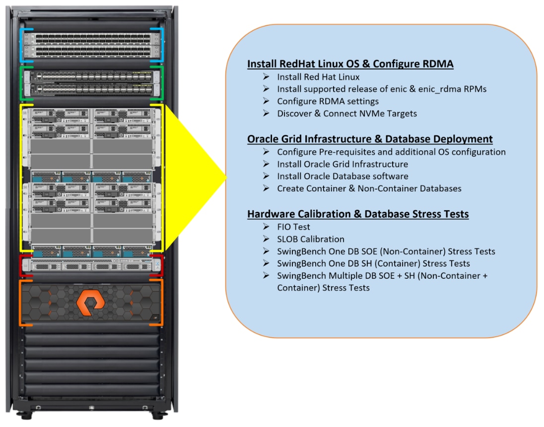
Operating System Configuration
To configure the operating system, follow these steps:
1. Launch KVM console on desired server by going to tab Equipment > Chassis > Chassis 1 > Servers > Server 1 > from right side windows General > and select KVM Console to open KVM.
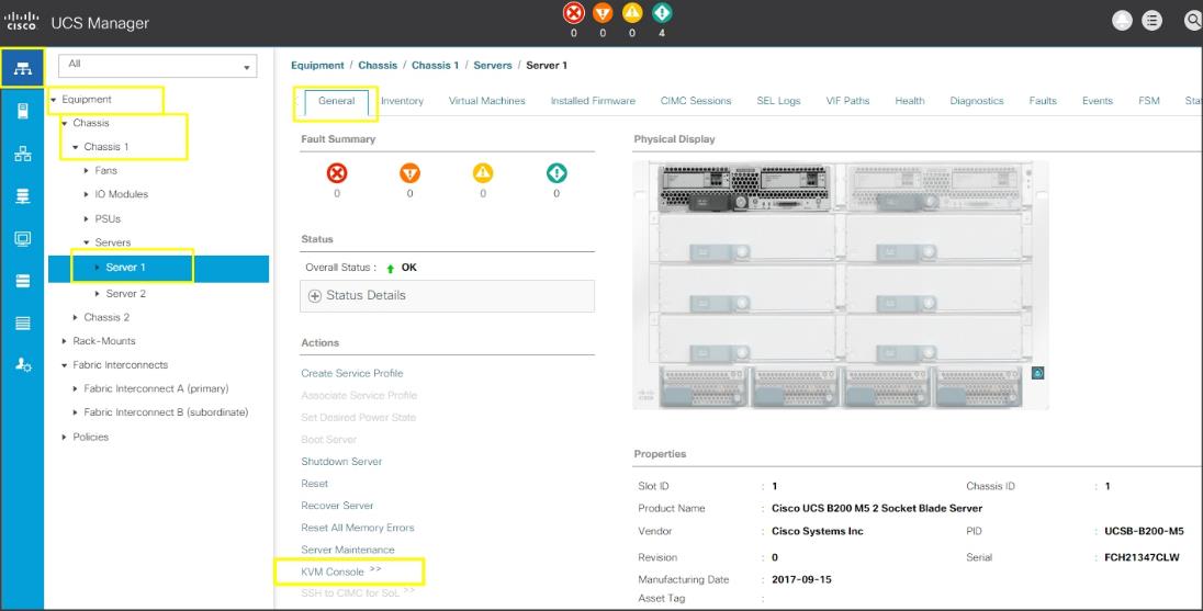
2. Click Accept security and open KVM. Enable virtual media, map the Red Hat Linux 7.6 ISO image and reset the server.
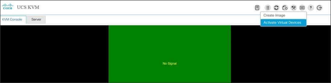
When the server starts booting, it will detect the Local Disk and the virtual media connected as Red Hat Linux CD. The server should launch the Red Hat Linux installer.
3. Select a language and assign the Installation destination as Local Disk. Apply hostname and click Configure Network to configure all network interfaces. Alternatively, you can only configure Public Network in this step. You can configure additional interfaces as part of post install steps.
![]() As a part of additional RPM package, we recommend selecting Customize Now and configure UEK kernel Repo.
As a part of additional RPM package, we recommend selecting Customize Now and configure UEK kernel Repo.
4. After the OS install, reboot the server, complete the appropriate registration steps. You can choose to synchronize the time with the ntp server. Alternatively, you can choose to use Oracle RAC cluster synchronization daemon (OCSSD). Both ntp and OCSSD are mutually exclusive and OCSSD will be setup during GRID install if ntp is not configured.
Configure Public, Private and Storage Interfaces
If you have not configured network settings during OS installation, then configure it now. Each node must have at least four network interface cards (NIC), or network adapters. One network interface is for the public network traffic, one interface is for the private network traffic (the node interconnects) and the two interfaces are for storage network RoCE traffic. As described earlier, 4 vNIC for each linux host were configured so you can configure networks.
Login as a root user into each node and go to /etc/sysconfig/network-scripts and configure Public network, Private network, Storage Network IP Address. Configure the private, public and storage NICs with the appropriate IP addresses across all the Oracle RAC nodes.
Operating System Prerequisites for NVMe/RoCE Configuration
To configure Linux host and enable NVMe storage targets, follow these steps:
1. As explained in the UCSM configuration section, you configured two vNIC and enabled NVMe/RoCE on those vNIC to access the storage array using NVMe over Fabrics.
2. Install an updated and supported RHEL kernel. For this solution, we installed RHEL 7.6 and configured RHEL Kernel to the version 3.10.0-957.27.2.el7.x86_64.
3. After the kernel upgrade, install the Cisco UCS supported enic and enic_rdma relevant rpm to match the supported NIC drivers. For this solution, we configured the following enic driver version:
[root@orarac1 ~]# rpm -q kmod-enic
kmod-enic-4.0.0.6-802.21.rhel7u6.x86_64
[root@orarac1 ~]# rpm -q kmod-enic_rdma
kmod-enic_rdma-1.0.0.6-802.21.rhel7u6.x86_64
![]() You should use a matching enic and enic_rdma pair. Review the Cisco UCS supported driver release for more information about the supported kernel version.
You should use a matching enic and enic_rdma pair. Review the Cisco UCS supported driver release for more information about the supported kernel version.
![]() To download the supported driver, go to https://software.cisco.com/download/home/283853163/type/283853158/release/4.1(1a)
To download the supported driver, go to https://software.cisco.com/download/home/283853163/type/283853158/release/4.1(1a)
4. Enable and start the multipath service on the node.
[root@orarac1 ~]# mpathconf --enable
[root@orarac1 ~]# systemctl start multipathd.service
[root@orarac1 ~]# systemctl enable multipathd.service
5. Install nvme-cli tool rpm on the node. Create an NQN for the host and put it in /etc/nvme/hostnqn file. This needs to be persistent.
[root@orarac1 ~]# nvme gen-hostnqn
nqn.2014-08.org.nvmexpress:uuid:0ee84155-f53d-42c8-9998-d1b771613980
[root@orarac1 ~]# echo nqn.2014-08.org.nvmexpress:uuid:0ee84155-f53d-42c8-9998-d1b771613980 > /etc/nvme/hostnqn
![]() The NVMe Qualified Name (NQN) is used to identify the remote NVMe storage target. It is similar to an iSCSI Qualified Name (IQN). If the file /etc/nvme/hostnqn doesn’t exist, then create the new one and update it as shown above.
The NVMe Qualified Name (NQN) is used to identify the remote NVMe storage target. It is similar to an iSCSI Qualified Name (IQN). If the file /etc/nvme/hostnqn doesn’t exist, then create the new one and update it as shown above.
6. Add this Linux host into Pure storage array by Log into storage array and then navigate to Storage > Hosts > and then click + sign to add host into pure storage array as shown below.
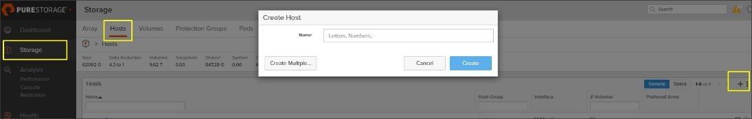
7. After creating the host name into storage array, select the created host name. Then go to option Host Ports and then select Configure NQNs. Enter the NQN details from the above Host NQN entry and add the host.
8. Configure file /etc/modules-load.d/ as shown below:
[root@orarac1 ~]# cat /etc/modules-load.d/nvme_rdma.conf
nvme_rdma
9. To configure the TOS settings on Linux Host, configure the following script (these settings are non-persistent):
for f in `ls /sys/class/infiniband`;
do
echo "setting TOS for IB interface:" $f
mkdir -p /sys/kernel/config/rdma_cm/$f/ports/1
echo 186 > /sys/kernel/config/rdma_cm/$f/ports/1/default_roce_tos
done
10. The best way to make it persistent is to create a script and the execute it as a service on startup. Use the following script file into the Linux host:
[root@orarac1 nvme]# cat /opt/nvme_tos.sh
#!/bin/bash
for f in `ls /sys/class/infiniband`;
do
echo "setting TOS for IB interface:" $f
mkdir -p /sys/kernel/config/rdma_cm/$f/ports/1
echo 186 > /sys/kernel/config/rdma_cm/$f/ports/1/default_roce_tos
done
11. Change the permission for the above file:
[root@orarac1 nvme]# chmod +x /opt/nvme_tos.sh
12. To create a file to connect nvme devices after node reboot by writing the following script:
[root@orarac1 nvme]# cat nvme_discover_connect.sh
#!/bin/bash
modprobe nvme-rdma
nvme connect -t rdma -a 200.200.11.3 -n nqn.2010-06.com.purestorage:flasharray.1d77a305a2e7000d
nvme connect -t rdma -a 200.200.11.4 -n nqn.2010-06.com.purestorage:flasharray.1d77a305a2e7000d
nvme connect -t rdma -a 200.200.12.3 -n nqn.2010-06.com.purestorage:flasharray.1d77a305a2e7000d
nvme connect -t rdma -a 200.200.12.4 -n nqn.2010-06.com.purestorage:flasharray.1d77a305a2e7000d
13. Change the permission on the above file:
[root@orarac1 nvme]# chmod +x /opt/nvme_discover_connect.sh
14. Create a service to use that script and enable it:
[root@orarac1 nvme]# vi /etc/systemd/system/nvme_tos.service
[root@orarac1 nvme]# cat /etc/systemd/system/nvme_tos.service
[Unit]
Description=RDMA TOS persistence
Requires=network.services
After=systemd-modules-load.service network.target
[Service]
Type=oneshot
ExecStart=/opt/nvme_tos.sh
ExecStart=/opt/nvme_discover_connect.sh
StandardOutput=journal
[Install]
WantedBy=default.target
15. Change the permission on the above file:
[root@orarac1 nvme]# chmod +x /etc/systemd/system/nvme_tos.service
16. Start the service to make sure there are no errors and enable it to start at each boot.
[root@orarac1 nvme]# systemctl start nvme_tos.service
[root@orarac1 nvme]# systemctl enable nvme_tos.service
Created symlink from /etc/systemd/system/default.target.wants/nvme_tos.service to /etc/systemd/system/nvme_tos.service.
17. Load the nvme driver and discover the rdma target as (nvme discover –t rdma –a <ip address>)
[root@orarac1 ~]# modprobe nvme-rdma
[root@orarac1 ~]# nvme discover -t rdma -a 200.200.11.3
Discovery Log Number of Records 2, Generation counter 2
=====Discovery Log Entry 0======
trtype: rdma
adrfam: ipv4
subtype: nvme subsystem
treq: not required
portid: 0
trsvcid: 4420
subnqn: nqn.2010-06.com.purestorage:flasharray.1d77a305a2e7000d
traddr: 200.200.11.3
rdma_prtype: roce-v2
rdma_qptype: connected
rdma_cms: rdma-cm
rdma_pkey: 0x0000
=====Discovery Log Entry 1======
trtype: rdma
adrfam: ipv4
subtype: discovery subsystem
treq: not required
portid: 0
trsvcid: 4420
subnqn: nqn.2014-08.org.nvmexpress.discovery
traddr: 200.200.11.3
rdma_prtype: roce-v2
rdma_qptype: connected
rdma_cms: rdma-cm
rdma_pkey: 0x0000
18. Discover the remaining RDMA target:
[root@orarac1 ~]# nvme discover -t rdma -a 200.200.11.4
[root@orarac1 ~]# nvme discover -t rdma -a 200.200.12.3
[root@orarac1 ~]# nvme discover -t rdma -a 200.200.12.4
19. After discovering all the target ports, connect to the target:
nvme connect -t rdma –a <ip address> -n <storage nqn>
[root@orarac1 ~]# nvme connect -t rdma -a 200.200.11.3 -n nqn.2010-06.com.purestorage:flasharray.1d77a305a2e7000d
[root@orarac1 ~]# nvme connect -t rdma -a 200.200.11.4 -n nqn.2010-06.com.purestorage:flasharray.1d77a305a2e7000d
[root@orarac1 ~]# nvme connect -t rdma -a 200.200.12.3 -n nqn.2010-06.com.purestorage:flasharray.1d77a305a2e7000d
[root@orarac1 ~]# nvme connect -t rdma -a 200.200.12.4 -n nqn.2010-06.com.purestorage:flasharray.1d77a305a2e7000d
20. Reboot the Linux host and make sure the nvme driver is loading and the Linux host can discover the rdma targets.
This concludes the NVMe/RoCE setup for the first Linux host.
21. Repeat steps 1-20 on each Linux host to enable and configure NVMe/RoCE storage connectivity. Next, you will configure the operating system prerequisites to install Oracle Grid and Oracle Database Software as explained in the following sections.
Operating System Prerequisites for Oracle Software Installation
Configure BIOS
This section describes how to optimize the BIOS settings to meet requirements for the best performance and energy efficiency for the Cisco UCS M5 generation of blade servers.
Configure BIOS for OLTP Workloads
OLTP systems are often decentralized to avoid single points of failure. Spreading the work over multiple servers can also support greater transaction processing volume and reduce response time. Make sure to disable Intel IDLE driver in the OS configuration section. When the Intel idle driver is disabled, the OS uses acpi_idle driver to control the c-states.
The settings explained in Cisco UCS configuration are the recommended options for optimizing OLTP workloads on Cisco UCS M5 platforms managed by Cisco UCS Manager.
For more information about BIOS settings, refer to: https://www.cisco.com/c/dam/en/us/products/collateral/servers-unified-computing/ucs-b-series-blade-servers/whitepaper_c11-740098.pdf
If the CPU gets into a deeper C-state and is not able to get out to deliver full performance quickly, there will be unwanted latency spikes for workloads. To address this, it is recommended to disable C-states in the BIOS. Oracle recommends disabling it from the OS level as well by modifying grub entries.
For this solution, configure the BIOS options by modifying in /etc/default/grub file as shown below:
[root@orarac1 ~]# cat /etc/default/grub
GRUB_TIMEOUT=5
GRUB_DISTRIBUTOR="$(sed 's, release .*$,,g' /etc/system-release)"
GRUB_DEFAULT=saved
GRUB_DISABLE_SUBMENU=true
GRUB_TERMINAL_OUTPUT="console"
GRUB_CMDLINE_LINUX="crashkernel=auto rd.lvm.lv=ol/root rd.lvm.lv=ol/swap rhgb quiet numa=off transparent_hugepage=never biosdevname=0 net.ifnames=0 intel_idle.max_cstate=0 processor.max_cstate=0"
GRUB_DISABLE_RECOVERY="true"
![]() For latency sensitive workloads, it is recommended to disable C-states in both OS and BIOS.
For latency sensitive workloads, it is recommended to disable C-states in both OS and BIOS.
Prerequisites Automatic Installation
After installing Red Hat Linux 7.6 (3.10.0-957.27.2.el7.x86_64) on all the server nodes (ORARAC1 to ORARAC8), you must configure the operating system prerequisites on all the eight nodes to successfully install Oracle RAC Database 19C.
For more information, refer to section Configuring Operating Systems for Oracle Grid Infrastructure on Linux, in the Grid Infrastructure Installation and Upgrade Guide for Linux Guide.
To configure operating system prerequisites for Oracle 19c software on all nodes, configure the prerequisites by installing the oracle-database-preinstall-19c rpm package. You can also download the required packages from http://public-yum.oracle.com/oracle-linux-7.html.
If you plan to use the oracle-database-preinstall-19c rpm package to perform all your prerequisite setup automatically, then login as root user and issue the following command:
[root@orarac1 ~]# yum install oracle-database-preinstall-19c
Additional Prerequisites Setup
After configuring automatic or manual prerequisites steps, you have to configure a few additional steps to complete the prerequisites for the Oracle database software installations on all the eight nodes as described in the following sections.
Disable SELinux
As most of the Organizations might already be running hardware-based firewalls to protect their corporate networks, we disabled Security Enhanced Linux (SELinux) and the firewalls at the server level for this reference architecture.
You can set secure Linux to permissive by editing the "/etc/selinux/config" file, making sure the SELINUX flag is set as follows:
SELINUX=permissive
Disable Firewall
Check the status of the firewall by running following commands. (The status displays as active (running) or inactive (dead)). If the firewall is active / running, to stop it, enter the following command:
systemctl status firewalld.service
systemctl stop firewalld.service
Also, to prevent the firewall from reloading when you restart the host machine, completely disable the firewall service by running the following command:
systemctl disable firewalld.service
Create the Grid User
To create the grid user, run the following command:
useradd –u 54322 –g oinstall –G dba grid
Set the Users Passwords
To change the password for Oracle and Grid users, run the following command:
passwd oracle
passwd grid
Configure Multipath
With DM-Multipath, you can configure multiple I/O paths between a host and storage controllers into a single device. If one path fails, DM-Multipath reroutes I/Os to the remaining paths. Configure multipath to access the LUNs presented from Pure Storage to the nodes as shown below.
![]() To implement Pure Storage’s recommendations to configuring the multipath, go to: https://support.purestorage.com/Solutions/Linux/Reference/Linux_Recommended_Settings
To implement Pure Storage’s recommendations to configuring the multipath, go to: https://support.purestorage.com/Solutions/Linux/Reference/Linux_Recommended_Settings
![]() For more information, go to: https://support.purestorage.com/Solutions/Oracle/Oracle_on_FlashArray/Oracle_Database_Recommended_Settings_for_FlashArray
For more information, go to: https://support.purestorage.com/Solutions/Oracle/Oracle_on_FlashArray/Oracle_Database_Recommended_Settings_for_FlashArray
Add or modify /etc/multipath.conf file accordingly to give the alias name of each volume presented from Pure Storage FlashArray as provided below into all eight nodes:
[root@orarac1 ~]# cat /etc/multipath.conf | more
defaults {
path_selector "queue-length 0"
path_grouping_policy multibus
fast_io_fail_tmo 10
no_path_retry 0
features 0
dev_loss_tmo 60
polling_interval 10
user_friendly_names no
}
multipaths {
multipath {
wwid eui.0073b45e390db04a24a9372f000129ed
alias dg_orarac_crs
}
}
You will add more LUNs and associated wwid into /etc/multipath.conf file later as you add more LUNs for Databases.
Configure UDEV Rules
You need to configure UDEV rules to assign permission in all the Oracle RAC nodes to access Pure Storage LUNs. This includes the device details along with required permissions to enable grid and oracle user to have read/write privileges on these devices. Configure UDEV rules on all the Oracle Nodes as shown below.
Create a new file named /etc/udev/rules.d/99-oracleasm.rules with the following entries on all nodes:
#All volumes which starts with dg_orarac_* #
ENV{DM_NAME}=="dg_orarac_crs", OWNER:="grid", GROUP:="oinstall", MODE:="660"
#All volumes which starts with dg_oradata_* #
ENV{DM_NAME}=="dg_oradata_*", OWNER:="oracle", GROUP:="oinstall", MODE:="660"
#All volumes which starts with dg_oraredo_* #
ENV{DM_NAME}=="dg_oraredo_*", OWNER:="oracle", GROUP:="oinstall", MODE:="660"
Create a new file named /etc/udev/rules.d/99-pure-storage.rules with the following entries on all nodes:
# Recommended settings for Pure Storage FlashArray.
# Use noop scheduler for high-performance solid-state storage
ACTION=="add|change", KERNEL=="sd*[!0-9]", SUBSYSTEM=="block", ENV{ID_VENDOR}=="PURE", ATTR{queue/scheduler}="noop"
# Reduce CPU overhead due to entropy collection
ACTION=="add|change", KERNEL=="sd*[!0-9]", SUBSYSTEM=="block", ENV{ID_VENDOR}=="PURE", ATTR{queue/add_random}="0"
# Spread CPU load by redirecting completions to originating CPU
ACTION=="add|change", KERNEL=="sd*[!0-9]", SUBSYSTEM=="block", ENV{ID_VENDOR}=="PURE", ATTR{queue/rq_affinity}="2"
# Set the HBA timeout to 60 seconds
ACTION=="add", SUBSYSTEMS=="scsi", ATTRS{model}=="FlashArray ", RUN+="/bin/sh -c 'echo 60 > /sys/$DEVPATH/device/timeout'"
The /etc/multipath.conf for the Oracle ASM devices and udev rules for these devices should be configured on all the RAC nodes. Make sure the devices are visible, and permissions are enabled for the grid user on all the nodes.
Configure /etc/hosts
Login as a root user into node and edit /etc/hosts file. Provide details for Public IP Address, Private IP Address, SCAN IP Address and Virtual IP Address for all the nodes. Configure these settings in each Oracle RAC Nodes as shown below.
[root@orarac1 ~]# cat /etc/hosts
127.0.0.1 localhost localhost.localdomain localhost4 localhost4.localdomain4
### Public IP
10.29.135.121 orarac1 orarac1.ciscoucs.com
10.29.135.122 orarac2 orarac2.ciscoucs.com
10.29.135.123 orarac3 orarac3.ciscoucs.com
10.29.135.124 orarac4 orarac4.ciscoucs.com
10.29.135.125 orarac5 orarac5.ciscoucs.com
10.29.135.126 orarac6 orarac6.ciscoucs.com
10.29.135.127 orarac7 orarac7.ciscoucs.com
10.29.135.128 orarac8 orarac8.ciscoucs.com
### Virtual IP
10.29.135.129 orarac1-vip orarac1-vip.ciscoucs.com
10.29.135.130 orarac2-vip orarac2-vip.ciscoucs.com
10.29.135.131 orarac3-vip orarac3-vip.ciscoucs.com
10.29.135.132 orarac4-vip orarac4-vip.ciscoucs.com
10.29.135.133 orarac5-vip orarac5-vip.ciscoucs.com
10.29.135.134 orarac6-vip orarac6-vip.ciscoucs.com
10.29.135.135 orarac7-vip orarac7-vip.ciscoucs.com
10.29.135.136 orarac8-vip orarac8-vip.ciscoucs.com
### Private IP
200.200.10.121 orarac1-priv orarac1-priv.ciscoucs.com
200.200.10.122 orarac2-priv orarac2-priv.ciscoucs.com
200.200.10.123 orarac3-priv orarac3-priv.ciscoucs.com
200.200.10.124 orarac4-priv orarac4-priv.ciscoucs.com
200.200.10.125 orarac5-priv orarac5-priv.ciscoucs.com
200.200.10.126 orarac6-priv orarac6-priv.ciscoucs.com
200.200.10.127 orarac7-priv orarac7-priv.ciscoucs.com
200.200.10.128 orarac8-priv orarac8-priv.ciscoucs.com
### SCAN IP
10.29.135.137 orarac-scan orarac-scan.ciscoucs.com
10.29.135.138 orarac-scan orarac-scan.ciscoucs.com
10.29.135.139 orarac-scan orarac-scan.ciscoucs.com
10.29.135.120 ora19c-client ora19c-client.ciscoucs.com
You must configure the following addresses manually in your corporate setup:
· A Public IP Address for each node
· A Virtual IP address for each node
· Three single client access name (SCAN) address for the oracle database cluster
All the steps listed (above) were performed on all of the eight nodes. These steps complete the prerequisite for Oracle Database 19c Installation at OS level on Oracle RAC Nodes.
Configure Pure Storage Host Group and LUN for OCR and Voting Disk
To share LUN’s across multiple hosts, you need to create and configure a Host Group on the storage array. To create a Host Group on the storage array and add all the eight nodes into that host group, follow this step:
1. Go to > Storage > Hosts > and select “+” option from the “Host Groups” option to create Host Group as shown below.

You have created CRS Volume of 200 GB for storing OCR and Voting Disk files for all the database. You have assigned this LUN to the Oracle RAC Host Group. Attach the LUN to a host group by going to the Connected Hosts and Host Groups tab under the volume context menu, click the Settings icon and select Connect Host Group. Select the host group where this LUN should be attached and click Confirm.
When all the O.S level prerequisites are completed, you are ready to install Oracle Grid Infrastructure as a grid user. Download Oracle Database 19c Release (19.3) for Linux x86-64 and Oracle Database 19c Release Grid Infrastructure (19.3) for Linux x86-64 software from Oracle Software site. Copy these software binaries to Oracle RAC Node 1 and Unzip all files into appropriate directories
These steps complete the prerequisite for Oracle Database 19c Installation at OS level on Oracle RAC Nodes.
Oracle Database 19c GRID Infrastructure Deployment
This section describes the high-level steps for Oracle Database 19c RAC install. It is not within the scope of this document to include the specifics of an Oracle RAC installation; you should refer to the Oracle installation documentation for specific installation instructions for your environment. We will provide a partial summary of details that might be relevant. For more information, use this link for Oracle Database 19c install and upgrade guide: https://docs.oracle.com/en/database/oracle/oracle-database/19/cwlin/index.html
For this solution, you will install Oracle Grid and Database software on all the eight nodes (orarac1 to orarac8).
Oracle 19c Release 19.3 Grid Infrastructure (GI) was installed on the first node as grid user. The installation also configured and added the remaining 7 nodes as a part of the GI setup. We also configured Oracle ASM Filter Driver and ASM in Flex mode. The installation guides you through gathering all node information and configuring ASM devices and all the prerequisite validations for GI. Complete this procedure to install Oracle Grid Infrastructure software for Oracle Standalone Cluster:
Create Directory Structure
![]() Download and copy the Oracle Grid Infrastructure image files to the local node only. During installation, the software is copied and installed on all other nodes in the cluster.
Download and copy the Oracle Grid Infrastructure image files to the local node only. During installation, the software is copied and installed on all other nodes in the cluster.
Create directory structure appropriately according to your environment. For example:
mkdir -p /u01/app/19.3.0/grid
chown grid:oinstall /u01/app/19.3.0/grid
As the grid user, download the Oracle Grid Infrastructure image files and extract the files into the Grid home
cd /u01/app/19.3.0/grid
unzip -q download_location/grid.zip
Configure Oracle ASM Filter Driver and Shared Disk
Log in as the root user and set the environment variable ORACLE_HOME to the location of the Grid home:
export ORACLE_HOME=/u01/app/19.3.0/grid
Use Oracle ASM command line tool (ASMCMD) to provision the disk devices for use with Oracle ASM Filter Driver:
[root@orarac1 bin]# ./asmcmd afd_label OCRVOTE /dev/mapper/dg_orarac_crs --init
Verify the device has been marked for use with Oracle ASMFD:
[root@orarac1 bin]# ./asmcmd afd_lslbl /dev/mapper/dg_orarac_crs
--------------------------------------------------------------------------------
Label Duplicate Path
================================================================================
OCRVOTE /dev/mapper/dg_orarac_crs
Run Cluster Verification Utility
This step verifies that all the prerequisites are met to install Oracle Grid Infrastructure Software. Oracle Grid Infrastructure ships with the Cluster Verification Utility (CVU) that can run to validate pre and post installation configurations.
To run this utility, login as Grid User in Oracle RAC Node 1 and go to the directory where oracle grid software binaries are located. Run script named as runcluvfy.sh as follows:
./runcluvfy.sh stage -pre crsinst -n orarac1,orarac2,orarac3,orarac4,orarac5,orarac6,orarac7,orarac8 –verbose
Configure HugePages
HugePages is a method to have larger page size that is useful for working with a very large memory. For Oracle Databases, using HugePages reduces the operating system maintenance of page states, and increases Translation Lookaside Buffer (TLB) hit ratio.
Advantage of HugePages:
· HugePages are not swappable so there is no page-in/page-out mechanism overhead.
· HugePages uses fewer pages to cover the physical address space, so the size of "bookkeeping"(mapping from the virtual to the physical address) decreases, so it requires fewer entries in the TLB and so TLB hit ratio improves.
· HugePages reduces page table overhead. Also, HugePages eliminated page table lookup overhead: Since the pages are not subject to replacement, page table lookups are not required.
· Faster overall memory performance: On virtual memory systems each memory operation is two abstract memory operations. Since there are fewer pages to work on, the possible bottleneck on page table access is clearly avoided.
For this configuration, HugePages are used for all the OLTP and DSS workloads. For detailed information, refer to the Oracle guidelines:
After configuration, you are ready to install Oracle Grid Infrastructure and Oracle Database 19c standalone software. For this solution, install the Oracle binaries on the local disk of the nodes. The OCR, Data, and Redo Log files reside in the file system configured on FlashArray//X90 R2.
Log in as the grid user and start the Oracle Grid Infrastructure installer as detailed in the following section.
Install and Configure Oracle Database Grid Infrastructure Software
It is not within the scope of this document to include the specifics of an Oracle RAC installation. However, a partial summary of details that might be relevant is provided. Please refer to the Oracle installation documentation for specific installation instructions for your environment.
To install Oracle Database Grid Infrastructure Software, follow these steps:
1. Go to the grid home where the Oracle 19c Grid Infrastructure software has been unzipped and launch the installer as the "grid" user.
2. Start the Oracle Grid Infrastructure installer by running the following command:
./gridSetup.sh
3. Select option Configure Oracle Grid Infrastructure for a New Cluster, then click Next.
4. Select cluster configuration options Configure an Oracle Standalone Cluster, then click Next.
5. In the next window, enter the Cluster Name and SCAN Name fields. Enter the names for your cluster and cluster scan that are unique throughout your entire enterprise network. You can also select to Configure GNS if you have configured your domain name server (DNS) to send to the GNS virtual IP address name resolution requests.
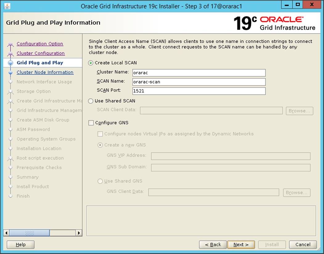
6. In Cluster node information window, click Add to add all eight nodes Public Hostname and Virtual Hostname as shown below:
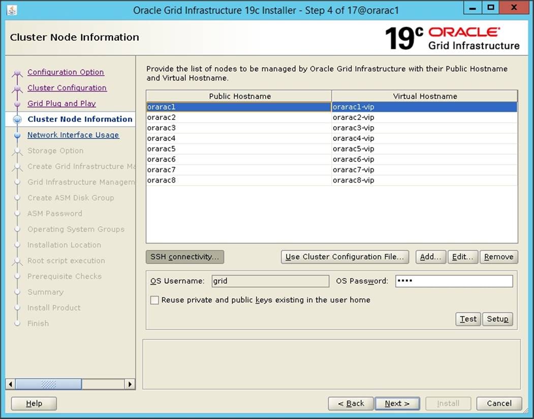
7. You will see all nodes listed in the table of cluster nodes. Click the SSH Connectivity button at the bottom of the window. Enter the operating system username and password for the Oracle software owner (grid). Click Setup.
8. A message window appears, indicating that it might take several minutes to configure SSH connectivity between the nodes. After some time, another message window appears indicating that password-less SSH connectivity has been established between the cluster nodes. Click OK to continue.
9. In Network Interface Usage screen, select the usage type for each network interface displayed as shown below:
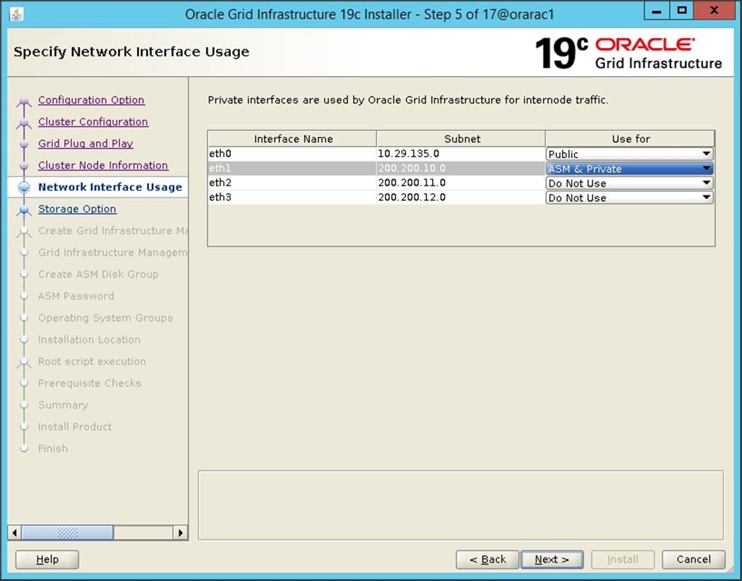
10. In the storage option window, select the “Use Oracle Flex ASM for storage” option and then click Next. For this solution, choose the No option for creating a separate ASM disk group for the Grid Infrastructure Management Repository data.
11. In the Create ASM Disk Group window, select the OCRVOTE LUNs assigned from Pure Storage to store OCR and Voting disk files. Enter the name of the disk group as OCRVOTE and select appropriate redundancy options as shown below and click Next.
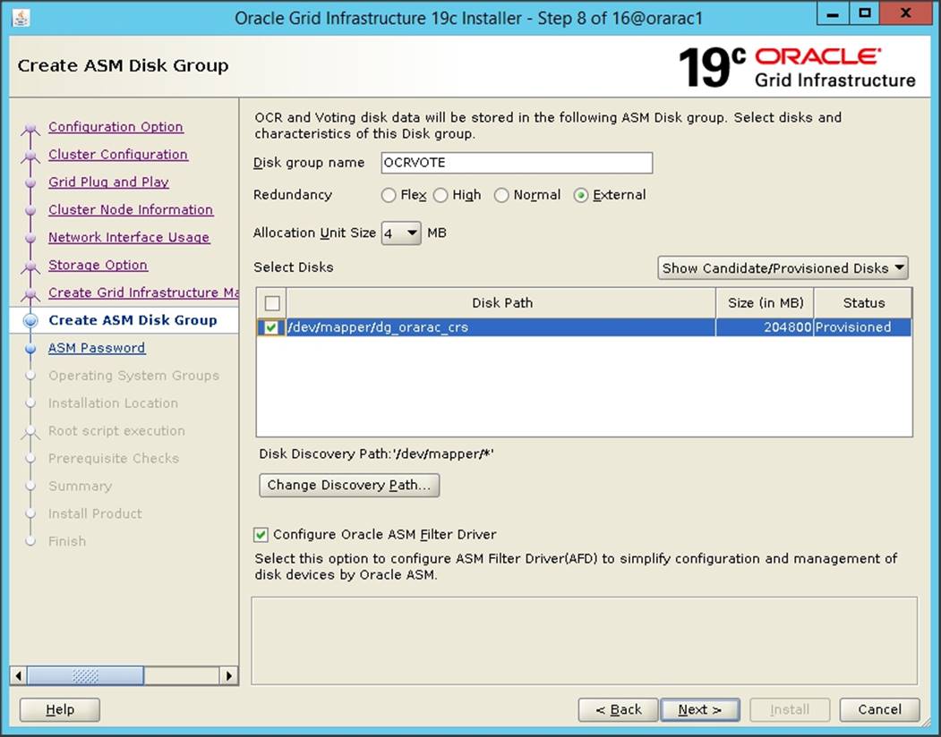
12. Choose the password for the Oracle ASM SYS and ASMSNMP account, then click Next.
13. For this solution, select the option Do not use Intelligent Platform Management Interface (IPMI). Click Next.
14. You can configure this instance of Oracle Grid Infrastructure and Oracle Automatic Storage Management to be managed by Enterprise Manager Cloud Control. For this solution, we did not select this option. Click Next.
![]() You can choose to set it up according to your requirements.
You can choose to set it up according to your requirements.
15. Select the appropriate operating system group names for Oracle ASM according to your environments.
16. Specify the Oracle base and Inventory directory to use for the Oracle Grid Infrastructure installation and then click Next. The Oracle base directory must be different from the Oracle home directory. Click Next and specify the Inventory Directory according to your setup.
17. Click Automatically run configuration scripts to run scripts automatically and enter the root user credentials. Click Next.
18. Wait while the prerequisite checks complete. If you have any issues, use the "Fix & Check Again" button. If any of the checks have a status of Failed and are not fixable, then you must manually correct these issues. After you have fixed the issue, you can click the Check Again button to have the installer re-check the requirement and update the status. Repeat as needed until all the checks have a status of Succeeded. Then Click Next
19. Review the contents of the Summary window and then click Install. The installer displays a progress indicator enabling you to monitor the installation process.
20. Wait for the grid installer configuration assistants to complete.

21. When the configuration completes successfully, click Close to finish and exit the grid installer.
22. When GRID install is successful, login to each of the nodes and perform minimum health checks to make sure that Cluster state is healthy. After your Oracle Grid Infrastructure installation is complete, you can install Oracle Database on a cluster node for high availability or install Oracle RAC.
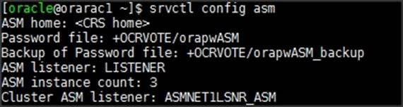
![]()
Oracle Database Installation
After successfully installing the Oracle GRID software, we recommend installing the Oracle Database 19c software only. You can create databases using DBCA or database creation scripts at later stage. It is not within the scope of this document to include the specifics of an Oracle RAC database installation. However, a partial summary of details that might be relevant is provided. Please refer to the Oracle database installation documentation for specific installation instructions for your environment: https://docs.oracle.com/en/database/oracle/oracle-database/19/ladbi/index.html
To install Oracle Database software, follow these steps:
1. Start the runInstaller command from the Oracle Database 19c installation media where Oracle database software is located.
2. Select “Set Up Software Only” configuration option.
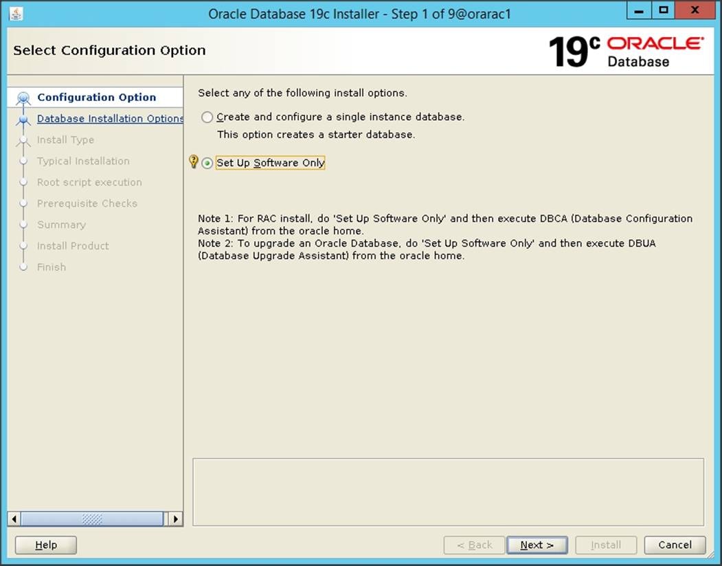
3. Select option "Oracle Real Application Clusters database installation" and click Next.
4. Select nodes in the cluster where installer should install Oracle RAC. For this setup, install the software on all eight nodes as shown below.

5. Click "SSH Connectivity..." and enter the password for the "oracle" user. Click Setup to configure passwordless SSH connectivity and the click Test to test it once it is complete. When the test is complete, click Next.
6. Select Database Edition Options according to your environments and then click Next.
7. Enter appropriate Oracle Base, then click Next.
8. Select the desired operating system groups, and then click Next.
9. Select option Automatically run configuration script from the option Root script execution menu and click Next.
10. Wait for the prerequisite check to complete. If there are, any problems either click Fix & Check Again or try to fix those by checking and manually installing required packages. Click Next.
11. Verify the Oracle Database summary information and then click Install.
12. After the installation of Oracle Database finishes successfully, click Close to exit the installer.
Overview of Oracle Flex ASM
Oracle ASM is Oracle's recommended storage management solution that provides an alternative to conventional volume managers, file systems, and raw devices. Oracle ASM is a volume manager and a file system for Oracle Database files that reduces the administrative overhead for managing database storage by consolidating data storage into a small number of disk groups. The smaller number of disk groups consolidates the storage for multiple databases and provides for improved I/O performance.
Oracle Flex ASM enables an Oracle ASM instance to run on a separate physical server from the database servers. With this deployment, larger clusters of Oracle ASM instances can support more database clients while reducing the Oracle ASM footprint for the overall system.

When using Oracle Flex ASM, Oracle ASM clients are configured with direct access to storage. With Oracle Flex ASM, you can consolidate all the storage requirements into a single set of disk groups. All these disk groups are mounted by and managed by a small set of Oracle ASM instances running in a single cluster. You can specify the number of Oracle ASM instances with a cardinality setting. The default is three instances.
Prior to Oracle 12c, if ASM instance on one of the RAC nodes crashes, all the instances running on that node will crash too. This issue has been addressed in Flex ASM; Flex ASM can be used even if all the nodes are hub nodes. However, GNS configuration is mandatory for enabling Flex ASM. You can check what instances relate to a simple query as shown below.
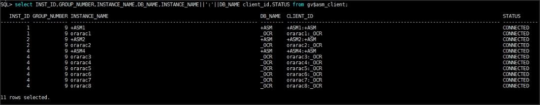
As you can see from the query (above), instance1 (orarac1), instance2 (orarac2) and instance4 (orarac4) are connected to +ASM. Also, the following screenshot shows a few more commands to check cluster and FLEX ASM details.
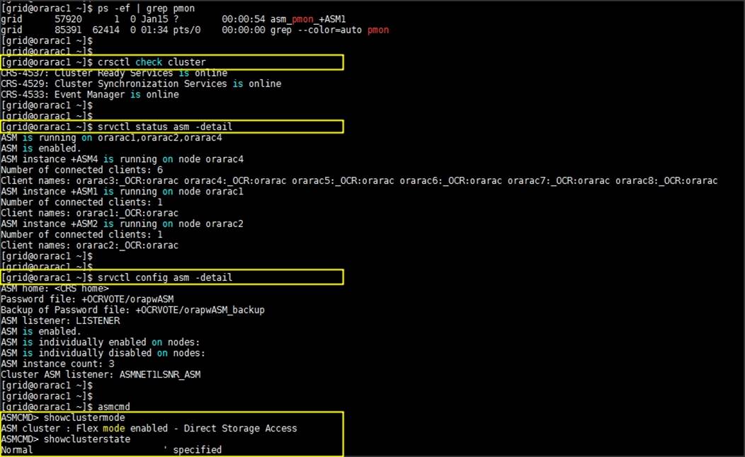
For more information, see: https://docs.oracle.com/en/database/oracle/oracle-database/19/ostmg/manage-flex-asm.html#GUID-DE759521-9CF3-45D9-9123-7159C9ED4D30
Oracle ASM Filter Driver (Oracle ASMFD)
During Oracle Grid Infrastructure installation, you can choose to install and configure Oracle Automatic Storage Management Filter Driver (Oracle ASMFD). Oracle ASMFD helps prevent corruption in Oracle ASM disks and files within the disk group. Oracle ASM Filter Driver (Oracle ASMFD) rejects write I/O requests that are not issued by Oracle software. This write filter helps to prevent users with administrative privileges from inadvertently overwriting Oracle ASM disks, thus preventing corruption in Oracle ASM disks and files within the disk group. For disk partitions, the area protected is the area on the disk managed by Oracle ASMFD, assuming the partition table is left untouched by the user.
Oracle ASMFD simplifies the configuration and management of disk devices by eliminating the need to rebind disk devices used with Oracle ASM each time the system is restarted. For more details, please refer to: https://docs.oracle.com/en/database/oracle/oracle-database/19/ladbi/about-oracle-asm-with-oracle-asm-filter-driver-asmfd.html#GUID-02BAA12B-51A3-4E05-B1C7-76DD05A94F51
Oracle Database Multitenant Architecture
The multitenant architecture enables an Oracle database to function as a multitenant container database (CDB). A CDB includes zero, one, or many customer-created pluggable databases (PDBs). A PDB is a portable collection of schemas, schema objects, and non-schema objects that appears to an Oracle Net client as a non-CDB. All Oracle databases before Oracle Database 12c were non-CDBs.
A container is a logical collection of data or metadata within the multitenant architecture. The following figure represents possible containers in a CDB.
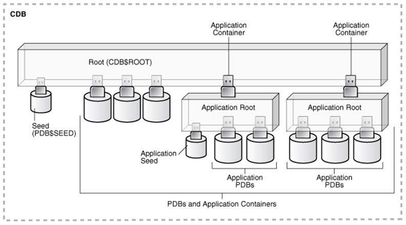
The multitenant architecture solves several problems posed by the traditional non-CDB architecture. Large enterprises may use hundreds or thousands of databases. Often these databases run on different platforms on multiple physical servers. Because of improvements in hardware technology, especially the increase in the number of CPUs, servers can handle heavier workloads than before. A database may use only a fraction of the server hardware capacity. This approach wastes both hardware and human resources. Database consolidation is the process of consolidating data from multiple databases into one database on one computer. The Oracle Multitenant option enables you to consolidate data and code without altering existing schemas or applications.
For more information on Oracle Database Multitenant Architecture, please refer to: https://docs.oracle.com/en/database/oracle/oracle-database/19/multi/introduction-to-the-multitenant-architecture.html#GUID-267F7D12-D33F-4AC9-AA45-E9CD671B6F22
In this solution, configure both types of databases to check performance of Non-Container Databases and Container Databases as explained in the next section.
Before configuring a database for workload tests, it is extremely important to validate that this is indeed a balanced configuration that can deliver expected performance. In this solution, we will test and validate nodes, user and performance scalability on all eight node Oracle RAC Databases with various benchmarking tools as explained below.
Hardware Calibration Using FIO
FIO is short for Flexible IO, a versatile IO workload generator. FIO is a tool that will spawn several threads or processes doing a particular type of I/O action as specified by the user. For our solution, we use FIO to measure the performance of a Pure storage device over a given period. For the FIO Tests, we created 8 LUNs and each LUNs was shared across all the eight nodes for read/write IO operations.
We run various FIO tests for measuring IOPS, Latency and Throughput performance of this solution by changing block size parameter into the FIO test. For each FIO test, we also changed the read/write ratio as 0/100 % read/write, 50/50 % read/write, 70/30 % read/write, 90/10 % read/write and 100/0 % read/write to scale the performance of the system. We also ran the tests for at least 3 hours to help ensure that this configuration can sustain this type of load for a longer period of time.
8k Random Read/Write IOPs Tests
The chart below shows results for the random read/write FIO test for the 8k block size representing OLTP type of workloads

For the 100/0 % read/write test, we achieved around 496k IOPS with the read latency around 0.9 millisecond. Similarly, for the 90/10 % read/write test, we achieved around 440k IOPS with the read latency around 0.8 millisecond and the write latency around 1 millisecond. For the 70/30 % read/write test, we achieved around 404k IOPS with the read latency around 0.7 millisecond and the write latency around 1.2 millisecond. For the 50/50 % read/write test, we achieved around 392k IOPS with the read latency around 0.7 millisecond and the write latency around 1.5 millisecond. For the 0/100 % read/write test, we achieved around 468k IOPS with the write latency around 1.8 millisecond
Bandwidth Test
The bandwidth tests were carried out with 512k IO Size and represents the DSS database type workloads. The chart below shows results for the sequential read/write FIO test for the 512k block size.

For the 100/0 % read/write test, we achieved around 13.5 GB/s throughput while for the 90/10 % read/write test we achieved around 13.28 GB/s throughput. For the 70/30 % read/write test, we achieved around 12.29 GB/s throughput and for the 50/50 % read/write test, we achieved around 10.63 throughput. For the 0/100 % read/write test, we achieved around 8.3 GB/s throughput.
As shown above, with all the eight nodes, you could generate about 13.15 GB/sec of sustained bandwidth over a 3 hour run period. We did not see any performance dips or degradation over the period of runtime. It is also important to note that this is not a benchmarking exercise and the numbers presented are not the peak numbers where there is hardware resource saturation. Now you are ready to create OLTP database(s) and continue with database tests
Database Creation with DBCA
We used Oracle Database Configuration Assistant (DBCA) to create two OLTP (DB Name as SLOB and OLTP) and one DSS (DB Name as DSSCDB) databases for SLOB and Swingbench test calibration. Alternatively, you can use Database creation scripts to create the databases as well. The database related files (data files, redo log files, control files, temp files, password file, parameter files, etc.) were placed on FlashArray//X90 R2 LUNs as listed in the below table. We have configured ASMFD and Flex ASM for this solution and configured two ASM disk group as DATA Disk Group for storing database related files and REDO Disk Group for storing Redo Log files for each database. We have used 8 LUNs to create Oracle ASM DATA disk group and 4 LUNs to create Oracle ASM REDO disk group for each database and all the LUNs were configured to use with Oracle ASM Filter Driver.
We deployed and tested both the non-container type of database as well as container type of database in this solution and recorded performance results as explained later in the section. The table below displays the storage layout of all the LUN configuration for all the databases used in this solution.
Table 10 Database LUN Configuration
| Database Name |
Type of Database |
ASM Disk Group |
Pure Storage LUN |
Size (G) |
Description |
| ASM |
|
OCRVOTE |
1 LUN (dg_orarac_crs) |
200 G |
OCR & Voting Disk |
| SLOB |
Non-Container Database |
DATASLOB |
8 LUNs (dg_oradata_slob01 to dg_oradata_slob08) |
500 G |
Data Files and Control Files for SLOB Database |
| REDOSLOB |
4 LUNs (dg_oraredo_slob01 to dg_oraredo_slob04) |
100 G |
Redo Log Files for SLOB Database |
||
| OLTP |
Non-Container Database |
DATAOLTP |
8 LUNs (dg_oradata_oltp01 to dg_oradata_oltp08) |
1250 G |
Data Files and Control Files for OLTP Database |
| REDOOLTP |
4 LUNs (dg_oraredo_oltp01 to dg_oraredo_oltp04) |
100 G |
Redo Log Files for OLTP Database |
||
| DSSCDB |
Container Database |
DATACDB |
4 LUNs (dg_oradata_cdb01 to dg_oradata_cdb04) |
200 G |
Data Files and Control Files for DSSCDB Container Database |
| REDOCDB |
4 LUNs (dg_oraredo_cdb01 to dg_oraredo_cdb04) |
200 G |
Redo Log Files for DSSCDB Container Database |
||
| PDBSH |
Pluggable Database plugged into DSSCDB Container Database |
DATASH |
8 LUNs (dg_oradata_pdbsh01 to dg_oradata_pdbsh08) |
1250 G |
Data Files and Control Files for PDBSH Pluggable Database |
As previously mentioned, we created a non-container database (DB Name – SLOB) for testing an Oracle I/O workload generation tool SLOB. We also have configured non-container (DB Name – ORCL) and container (DB Name – DSSCDB) type of database to stress test an Oracle database by using load generator and benchmarking tool Swingbench.
SLOB Calibration
We used the widely adopted SLOB and Swingbench database performance test tools to test and validate throughput, IOPS, and latency for various test scenarios as explained in the following section.
The Silly Little Oracle Benchmark (SLOB) is a toolkit for generating and testing I/O through an Oracle database. SLOB is very effective in testing the I/O subsystem with genuine Oracle SGA-buffered physical I/O. SLOB supports testing physical random single-block reads (db file sequential read) and random single block writes (DBWR flushing capability).
SLOB issues single block reads for the read workload that are generally 8K (as the database block size was 8K).
For testing the SLOB workload, we have created one non-container database as SLOB. We created two disk group to store the data and redo log files for the SLOB database. First disk group DATASLOB was created with 8 LUNs (500 GB each) while second disk-group REDOSLOB was created with four LUN (100 GB each). We loaded SLOB schema on DATASLOB disk group of up to 1.6 TB in size. The following tests were performed and various metrics like IOPS and latency were captured along with Oracle AWR reports for each test scenario.
User Scalability Test
SLOB was configured to run against all the eight RAC nodes and the concurrent users were equally spread across all the nodes. We tested the environment by increasing the number of Oracle users in database from a minimum of 32 users up to a maximum of 512 users across all the nodes. At each load point, we verified that the storage system and the server nodes could maintain steady-state behavior without failure. We also made sure that there were no bottlenecks across servers or networking systems
We performed User Scalability test with 32, 64, 128, 192, 256 and 512 users on 4 Oracle RAC nodes by varying read/write ratio as follows:
· Varying Workloads
- 100% read (0% update)
- 90% read (10% update)
- 70% read (30% update)
- 50% read (50% update)
Table 11 lists the total number of IOPS (both read and write) for user scalability test when run with 32, 64, 128, 192, 256, 384 and 512 Users on the SLOB database.
Table 11 Total IOPS for SLOB User Scale Test
| Users |
IOPS for Read/Write % (100/0) |
IOPS for Read/Write % (90/10) |
IOPS for Read/Write % (70/30) |
IOPS for Read/Write % (50/50) |
| 32 |
68,225 |
102,401 |
128,487 |
130,390 |
| 64 |
200,871 |
215,735 |
231,311 |
237,536 |
| 128 |
371,631 |
388,693 |
410,166 |
414,151 |
| 196 |
511,180 |
508,980 |
487,162 |
471,841 |
| 256 |
637,607 |
558,923 |
491,302 |
483,806 |
| 384 |
749,241 |
555,102 |
483,405 |
484,166 |
| 512 |
761,184 |
547,204 |
479,612 |
486,401 |
The following graphs demonstrate total number of IOPS while running SLOB workload for various concurrent users for each test scenario.

The graph above shows the total IOPS scale with increased users and similar IOPS from 32 users to 512 users with 100% read, 90% read, 70% read and 50% read.
The following AWR snapshot was captured from a 100% Read (0% update) Test scenario while running SLOB test for 512 users. The snapshot shows a section from the Oracle AWR report from the run that highlights Physical Reads/Sec and Physical Writes/Sec for each instance.

The screenshot above highlights that IO load is distributed across all the cluster nodes performing workload operations. Due to variations in workload randomness, we conducted multiple runs to ensure consistency in behavior and test results.
The following snapshot was captured from a 50% Read (50% update) Test scenario while running SLOB test for 512 users. The snapshot shows a section from AWR report from the run that highlights Physical Reads/Sec and Physical Writes/Sec for each instance.
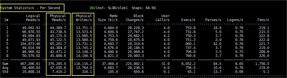
The following graph illustrates the latency exhibited by the FlashArray//X90 R2 across different workloads. All the workloads experienced less than and around 1 millisecond latency and it varied based on the workload. As expected, the 50% read (50% update) test exhibited higher latencies as the user count was increased. However, these are exceptional performance characteristics keeping the nature of the IO load.
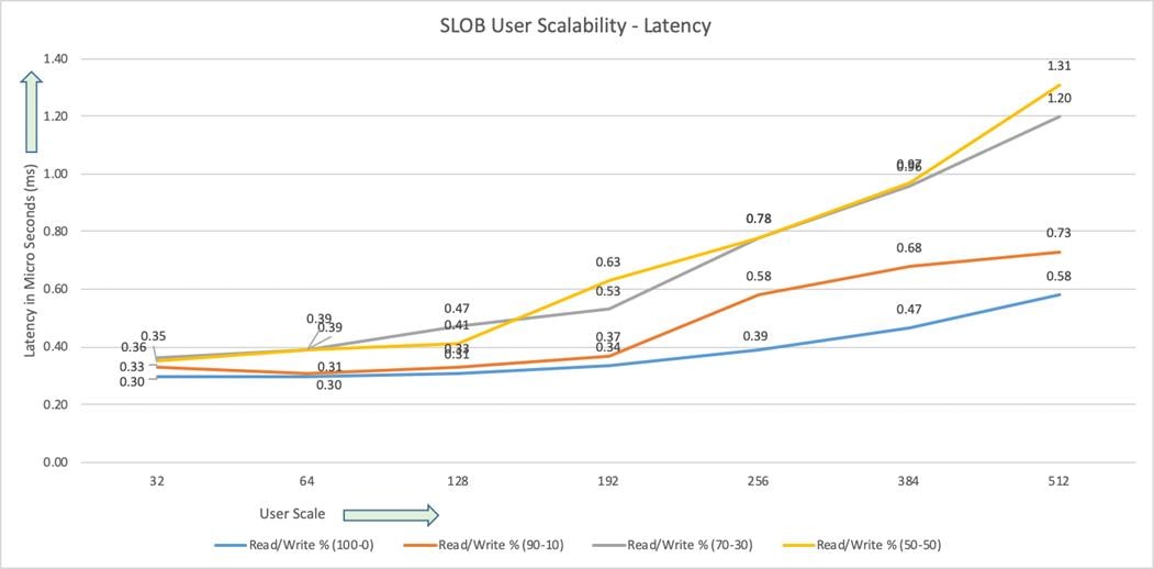
The following screenshot was captured from 50% Read (50% Update) Test scenario while running SLOB test. The snapshot shows a section from a 3-hour window of AWR report from the run that highlights Top Timed Events.

SwingBench Test
We used Swingbench for OLTP and DSS workload testing and deployed both types of databases (non-container and container) to check the performance of multitenant architecture. Swingbench is a simple to use, free, Java-based tool to generate database workload and perform stress testing using different benchmarks in Oracle database environments. Swingbench can be used to demonstrate and test technologies such as Real Application Clusters, Online table rebuilds, Standby databases, online backup and recovery, and so on.
Swingbench provides four separate benchmarks, namely, Order Entry, Sales History, Calling Circle, and Stress Test. For the tests described in this solution, Swingbench Order Entry benchmark was used for OLTP workload testing and the Sales History benchmark was used for the DSS workload testing.
The Order Entry benchmark is based on SOE schema and is TPC-C like by types of transactions. The workload uses a very balanced read/write ratio around 60/40 and can be designed to run continuously and test the performance of a typical Order Entry workload against a small set of tables, producing contention for database resources.
The Sales History benchmark is based on the SH schema and is TPC-H like. The workload is query (read) centric and is designed to test the performance of queries against large tables.
Typically encountered in the real-world deployments, we tested a combination of scalability and stress related scenarios that ran on all the 8-node Oracle RAC cluster configuration.
· OLTP database user scalability and OLTP database node scalability representing small and random transactions.
· DSS database workload representing larger transactions
· Mixed workload featuring OLTP and DSS database workloads running simultaneously for 24 hours
For Swingbench workload, we created one OLTP (Order Entry) and one DSS (Sales History) database to demonstrate database consolidation, multi-tenancy capability, performance and sustainability. We created approximately 3 TB of OLTP and 4 TB of DSS database to perform Order Entry and Sales Entry Swingbench workload testing.
The first step after the database creation is calibration; about the number of concurrent users, nodes, throughput, IOPS and latency for database optimization. For this solution, we have tested system performance with different databases running at a time and capture the results as explained in the following sections.
One OLTP Database Performance (OLTP Non-Container Database)
For one OLTP database workload featuring Order Entry schema, we have created one non-container database as OLTP. For the OLTP database (3 TB), we used 64GB size of System Global Area (SGA). We also ensured that HugePages were in use. The OLTP Database scalability test was run for at least 24 hours and made sure that results are consistent for the duration of the full run. We ran the SwingBench scripts on each node to start OLTP database and generate AWR reports for each scenario as shown below.
User Scalability
Table 12 lists the Transaction Per Minutes (TPM), IOPS and System Utilization for OLTP Databases while running Swingbench workloads from 100 users to 800 users.
Table 12 Transaction Per Minutes, IOPS, and System Utilization for OLTP Databases
| Users |
Transactions |
Storage IOPS |
CPU Utilization (%) |
|||
| Per Seconds (TPS) |
Per Minutes (TPM) |
Reads/Sec |
Writes/Sec |
Total Phy IOPS |
||
| 100 |
9,127 |
547,620 |
47,834 |
26,435 |
74,269 |
11.2 |
| 200 |
16,234 |
974,040 |
79,463 |
38,746 |
118,209 |
18.2 |
| 300 |
22,374 |
1,342,440 |
99,352 |
51,294 |
150,646 |
22.3 |
| 400 |
27,645 |
1,658,700 |
128,095 |
66,314 |
194,409 |
23.6 |
| 500 |
31,020 |
1,861,200 |
152,103 |
76,053 |
228,156 |
27.2 |
| 600 |
34,654 |
2,079,240 |
170,298 |
88,263 |
258,561 |
31.2 |
| 700 |
39,756 |
2,385,360 |
191,583 |
92,526 |
284,109 |
34.1 |
| 800 |
47,458 |
2,847,480 |
217,357 |
97,637 |
314,994 |
38.2 |
The following chart shows the IOPS and Latency of OLTP database while running Swingbench workload for 100 users to 800 users on all eight RAC nodes.

The following chart shows TPM and System Utilization of the system while running Swingbench workload for 100 users to 800 users.

The screenshot shown below was captured from the 800 User Scale Test scenario while running Swingbench workload on SOE database. The snapshot shows a section from a 24-hour window of AWR Global report from the run that highlights Physical Reads/Sec and Physical Writes/Sec for each instance. Notice that IO load is distributed across all the cluster nodes performing workload operations.
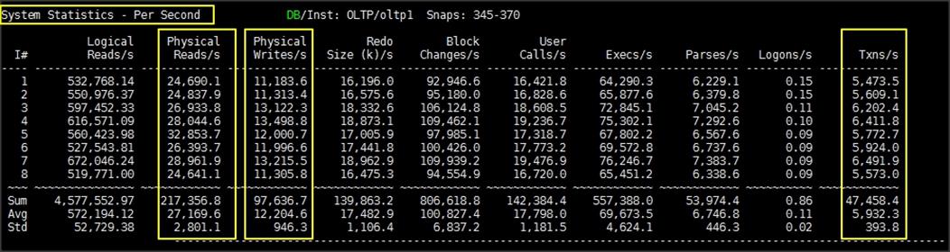
The AWR screenshot shown below shows top timed events for the same 800 User Scale Test while Swingbench test was running.
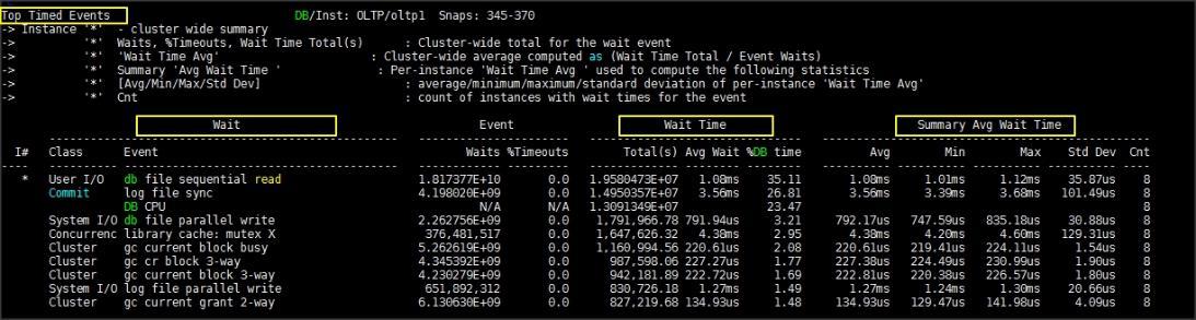
The AWR screenshot shown below shows the Interconnect Device Statistics for the same 800 Users Scale Test while Swingbench test was running. We observed interconnect statistics average 250MB/s on each of the node.

One DSS Database Performance (DSSCDB Container Database and PDBSH Pluggable Database)
DSS database workloads are generally sequential, read intensive and exercise large IO size. DSS database workload runs a small number of users that typically exercise extremely complex queries that run for hours. For running oracle database multitenant architecture, we configured one container database as DSSCDB and into that container, we created one pluggable database as PDBSH as shown below across the eight Oracle RAC nodes.
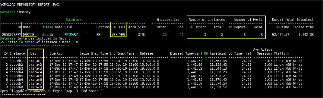
We configured 4 TB of PDBSH pluggable database by loading Swingbench sh schema into Datafile Tablespace. PDBSH Database activity is captured for eight Oracle RAC Instances using Oracle AWR for 24 hours workload test through container CDB. For 24-hour DSS workload test, we observed the total sustained IO bandwidth average was around 11.1 GB/sec after the initial ramp up workload. As shown in the below screenshot, the IO was consistent throughout the run and we did not observe any significant dips in performance for the complete period of time.
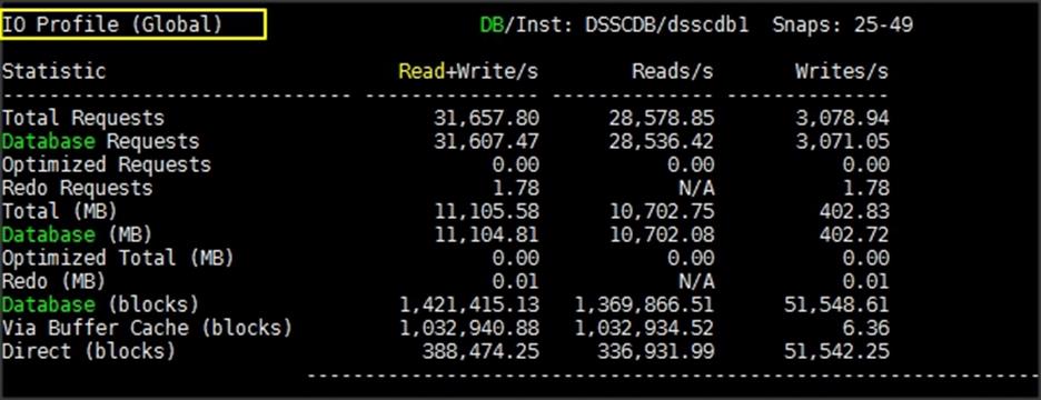
The screenshot shown below was captured from Oracle Enterprise Manager while database stress test was running across all the Oracle RAC nodes.

The screenshot shown below was captured from Oracle AWR report while running Swingbench SH workload on DSS database for 24 hours. The screenshot shown below shows top timed events while the Swingbench test was running across all eight Oracle RAC nodes.

The screenshot shown below shows the storage array performance captured while running Swingbench SH workload on DSS database across all eight Oracle RC nodes.

Multiple Database Performance (OLTP (Non-Container DB) + DSS (Container and Pluggable DB))
In this test, we used both non-container and container type of database together and performed stress tests on both the databases together as explained below. We run OLTP (OLTP) and DSS (PDBSH) Database Swingbench workload at the same time to measure the system performance on small random queries presented via OLTP databases as well as large and sequential transactions submitted via DSS database workload.
The screenshots shown below were captured from Oracle AWR reports while running the Swingbench workload tests on both the databases at the same time for 24 hours.

As shown above, for OLTP database, we achieved around 232k IOPS (Physical Reads/s – 160,349 and Physical Writes/s – 71,583) and 34,299 Transactions Per Seconds for OLTP database. As shown below for DSS Database, we achieved round 3.3 GB/s throughput while running both the databases workloads for 24-hour tests.

We also captured storage array performance by logging into storage array while running mixed workload for 24-Hour as shown in the below screenshot.

The screenshots shown below were captured from the Oracle Enterprise Manager while running the Swingbench workload tests on both the database simultaneously for 24 hours.
OLTP Database screenshot below shows Average Wait Time per Instance, IO Requests per Second and Average Host CPU Utilization as well as highlights Transactions per Seconds for 24 hour sustained run.
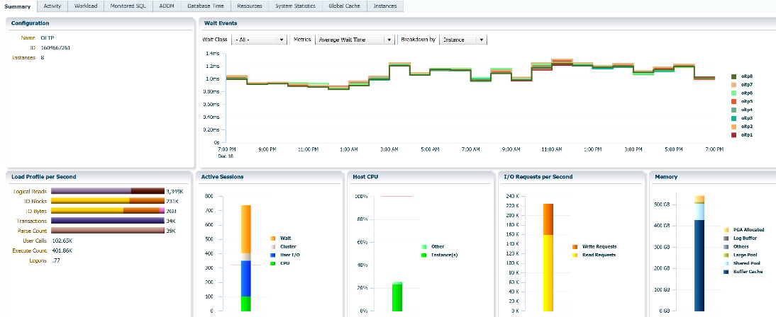
DSSCDB Database screenshot below shows Average Wait Time per Instance, IO Requests per Second and Average Host CPU Utilization as well as highlights IO Bytes per Second for 24 hour sustained run.
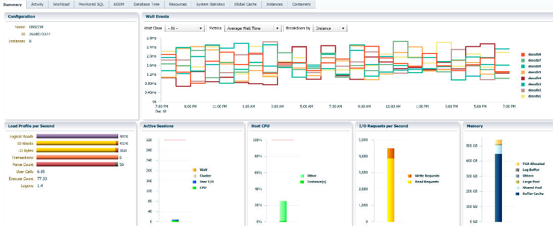
The screenshot below shows IO Requests per Second for OLTP Database while running mixed workload for 24-hour Swingbench Test.
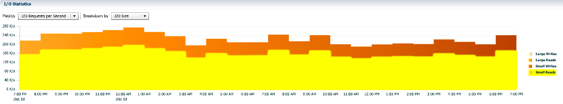
The screenshot below shows IO Bytes per Second for DSS (PDBSH) Database while running mixed workload for 24-hour Swingbench Test
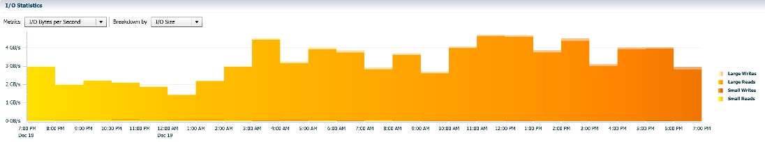
The screenshot below shows OLTP Database average IO Requests, Host CPU and Active Sessions per instance while running mixed workload for 24-hour stress tests.

The screenshot below shows DSS (PDBSH) Database average IO Throughput, Host CPU and Active Sessions per instance while running mixed workload for 24-hour stress tests. 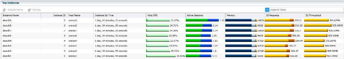
Hardware Failure Tests
The goal of these tests was to ensure that reference architecture withstands common or typical human errors. We conduct many hardware (disconnect power), software (process kills) and OS specific failures that simulate real world scenarios under stress conditions. In the destructive testing, we also demonstrate unique failover capabilities of Cisco UCS components. We have highlighted some of those test cases below.
Table 13 Hardware Failover Tests
| Test Scenario |
Tests Performed |
| Test 1 – UCS Chassis 1 and Chassis 2 IOM Links Failure |
Run the system on full Database workload. Disconnect one link from each Chassis 1 IOM and Chassis 2 IOM by pulling it out and reconnect it after 10 minutes. |
| Test 2 – UCS FI – A Failure |
Run the system on Full Database workload. Power Off Fabric Interconnect – A and check network traffic on Fabric Interconnect – B. |
| Test 3 – UCS FI – B Failure |
Run the system on Full Database workload. Power Off Fabric Interconnect – B and check network traffic on Fabric Interconnect – A. |
| Test 4 – Nexus Switch – A Failure |
Run the system on Full Database workload. Power Off Nexus Switch – A and check network traffic on Nexus Switch – B. |
| Test 5 – Nexus Switch – B Failure |
Run the system on Full Database workload. Power Off Nexus Switch – B and check network traffic on Nexus Switch – A. |
| Test 6 – Server Node Failure |
Run the system on Full Database workload. Power Off one Linux Host and check the Database Performance. |
The following architecture illustrates various failure scenario that can occur due to either unexpected crashes or hardware failures.

As shown above, Scenario 1 and/or 2 represents the Chassis 1 and/or Chassis 2 IOM Link Failure. Scenario 5 represents the UCS FI – A Failure and similarly, scenario 6 represents the Nexus Switch – A Failure. Scenario 7 represents one of the Server Node Failure. In this section, we will perform most of the above failure scenario and check the system performance as explained below.
The following snapshots show a complete infrastructure details of MAC address and VLAN information for UCS Fabric Interconnect – A and Fabric Interconnect – B Switches before failover test.
Log into Fabric Interconnect – A and type connect nxos a then type show mac address-table to see all VLAN connection on Fabric Interconnect – A as shown below.

As shown in the above screenshot, Fabric Interconnect – A carry Oracle Public Network traffic on VLAN 135 and Storage Network Traffic VLAN 11 under normal operating conditions before the failover tests.
Similarly, log into Fabric Interconnect – B and type connect nxos b then type show mac address-table to see all VLAN connection on Fabric – B as shown in the screenshot below.

As shown in the above screenshot, Fabric Interconnect – B carry Oracle Private Network traffic on VLAN 10 and Storage Network Traffic VLAN 12 under normal operating conditions before the failover tests.
![]() All the Hardware failover tests were conducted during all the databases (OLTP and DSS) running Swingbench workloads.
All the Hardware failover tests were conducted during all the databases (OLTP and DSS) running Swingbench workloads.
Test 1 – Cisco UCS Chassis 1 and Chassis 2 IOM Links Failure
We conducted IOM Links failure test on Cisco UCS Chassis 1 and Chassis by disconnecting one of the server port link cable from the Chassis as shown below.
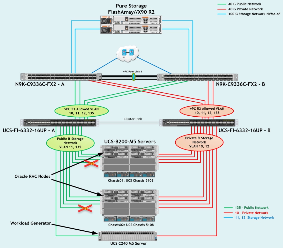
Unplug one server port cable from Chassis 1 and Chassis 2 and check the MAC address and VLAN traffic information on both UCS Fabric Interconnects. The screenshot below shows network traffic on Fabric Interconnect A when one link from Chassis 1 and one link from Chassis 2 IOM Failed.
The screenshot below shows network traffic on Fabric Interconnect B when one link from Chassis 1 and one link from Chassis 2 IOM Failed.
Also, we logged into the storage array and checked the database workload performance as shown below.

As shown this screenshot, we noticed no disruption in public, private and storage network traffic even after one failed traffic link from both the Chassis because of the Cisco UCS Port-Channel Feature.
Test 2 – Cisco UCS Fabric Interconnect – A Failure Test
We conducted a hardware failure test on Fabric Interconnect – A by disconnecting power cable to the Fabric Interconnect Switch.
The figure below illustrates how during Fabric Interconnect – A switch failure, the respective nodes (ORARAC1, ORARAC2, ORARAC3 and ORARAC4) on chassis 1 and nodes (ORARAC5, ORARAC6, ORARAC7 and ORARAC8) on chassis 2 will fail over the public network interface MAC addresses and its VLAN network traffic 135 to fabric interconnect – B.
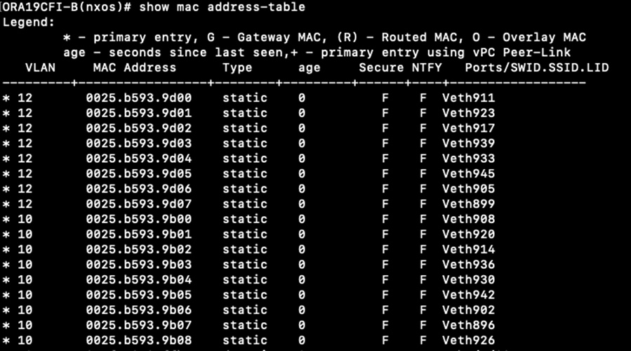
Log into Fabric Interconnect – B and type connect nxos a then type show mac address-table to see all VLAN connection on Fabric Interconnect – B.
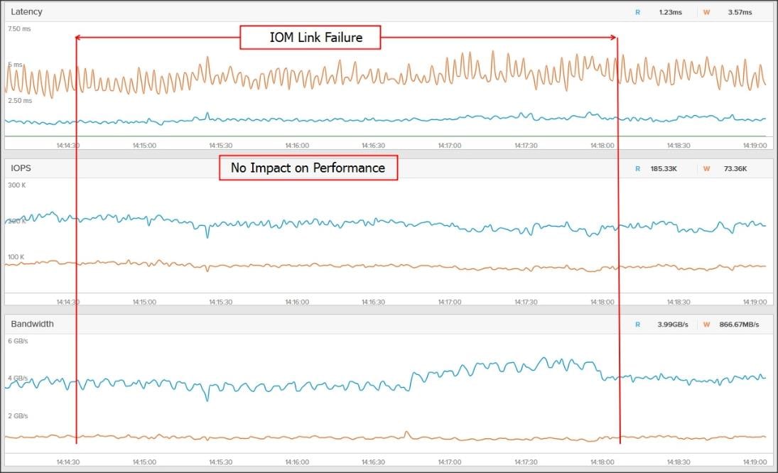
We noticed in the screenshot above, when the Fabric Interconnect – A failed, it would route all the Public Network traffic of VLAN 135 to Fabric Interconnect – B. So, Fabric Interconnect – A Failover did not cause any disruption to Private and Public Network Traffic.
![]() Fabric Failover on RDMA vNICs is not supported with this release of UCSM and the recommendation is to use host OS multipathing to take care of the FI failure or upgrade scenarios. The plan is to evaluate the feasibility of supporting fabric failover for RDMA enic as a future enhancement.
Fabric Failover on RDMA vNICs is not supported with this release of UCSM and the recommendation is to use host OS multipathing to take care of the FI failure or upgrade scenarios. The plan is to evaluate the feasibility of supporting fabric failover for RDMA enic as a future enhancement.
The following screenshot shows the pure storage array performance of the mixed workloads on both the databases while one of the Fabric Interconnect failed.

We also recorded performance of the databases from the Oracle Enterprise Manager and noticed no performance impact on IO Service Requests to the storage as shown in the below screenshot.
OLTP Database performance while Fabric Interconnect – A failure.

DSS Database performance while Fabric Interconnect – A failure.

When we disconnect power from Fabric Interconnect – A, we did not see any disruption in any Private, Public and Storage Network Traffic.
![]() Fabric failover times can vary depends upon various factors. We need to look at failover times and how they impact NVMe Keep Alives, out of order frame reception handling on Linux Host and Storage Target end. So, a manual step “nvme connect” must be issued from each of the host to connect to NVMe storage target once the FI comes back online. Alternatively, you can configure the script for connecting storage targets.
Fabric failover times can vary depends upon various factors. We need to look at failover times and how they impact NVMe Keep Alives, out of order frame reception handling on Linux Host and Storage Target end. So, a manual step “nvme connect” must be issued from each of the host to connect to NVMe storage target once the FI comes back online. Alternatively, you can configure the script for connecting storage targets.
After plugging back power cable to Fabric Interconnect – A Switch, the respective nodes (ORARAC1, ORARAC2, ORARAC3 and ORARAC4) on chassis 1 and nodes (ORARAC5, ORARAC6, ORARAC7 & ORARAC8) on chassis 2 will route back the MAC addresses and its VLAN public network traffic 135 to Fabric Interconnect – A. Also, we connected all the NVME storage targets on VLAN 11 manually by running the “nvme connect" commands to restore all the database nodes and storage connectivity. After restoring back all the nodes to storage connectivity, the operating system level multipath configuration will bring back all the path back to active and database performance will resume to normal operating state.
Test 3 – Cisco UCS Fabric Interconnect – B Failure Test
Similarly, we conducted a hardware failure test on Fabric Interconnect – B by disconnecting power cable to the Fabric Interconnect Switch.
The figure below illustrates how during Fabric Interconnect – B switch failure, the respective nodes (ORARAC1, ORARAC2, ORARAC3 and ORARAC4) on chassis 1 and nodes (ORARAC5, ORARAC6, ORARAC7 and ORARAC8) on chassis 2 will fail over the private network interface MAC addresses and its VLAN network traffic 10 to fabric interconnect – A.

Log into Fabric Interconnect – A and type connect nxos a then type show mac address-table to see all VLAN connection on Fabric Interconnect – A and observed the network traffic.
We noticed when the Fabric Interconnect – B failed, it would route all the Private network traffic of VLAN 10 to Fabric Interconnect – A. So, Fabric Interconnect – B Failover did not cause any disruption to Private and Public Network Traffic.
![]() Fabric Failover on RDMA vNICs is not supported with this release of UCSM and the recommendation is to use host OS multipathing to take care of the FI failure or upgrade scenarios. The plan is to evaluate the feasibility of supporting fabric failover for RDMA enic as a future enhancement.
Fabric Failover on RDMA vNICs is not supported with this release of UCSM and the recommendation is to use host OS multipathing to take care of the FI failure or upgrade scenarios. The plan is to evaluate the feasibility of supporting fabric failover for RDMA enic as a future enhancement.
Similar to the Fabric Interconnect – A failure test, we noticed no performance impact on IO Service Requests to both the database when Fabric Interconnect – B failure occurred.
After plugging back power cable to Fabric Interconnect – B Switch, the respective nodes (ORARAC1, ORARAC2, ORARAC3 & ORARAC4) on chassis 1 and nodes (ORARAC5, ORARAC6, ORARAC7 & ORARAC8) on chassis 2 will route back the MAC addresses and its VLAN private network traffic 10 to Fabric Interconnect – B. Also, we connected all the NVME storage targets on VLAN 12 manually by running the “nvme connect” commands to restore all the database nodes and storage connectivity.
Test 4 and 5 – Cisco UCS Nexus Switch – A or Nexus Switch – B Failure Test
We conducted a hardware failure test on Nexus Switch – A by disconnecting power cable to the switch and checking the MAC address and VLAN information on Cisco UCS Nexus Switch – B.

During Nexus Switch – A failure, it routed all the Private Network (VLAN 10), Public Network Traffic (VLAN 135) and Storage Network Traffic (VLAN 11 and VLAN 12) to Nexus Switch – B. So, Nexus Switch – A Failover did not cause any disruption to Private, Public and Storage Network Traffic.
Similarly, we conducted a hardware failure test on Nexus Switch – B by disconnecting power cable to the switch and checking the MAC address and VLAN information on Cisco UCS Nexus Switch – A. During Nexus Switch – B failure, it routed all the Private Network (VLAN 10), Public Network Traffic (VLAN 135) and Storage Network Traffic (VLAN 11 & VLAN 12) to Nexus Switch – A. So, Nexus Switch – B Failover did not cause any disruption to Private, Public and Storage Network Traffic.
Test 6 – Server Node Failure Test
We conducted a Server Node failure test on this solution by rebooting one node from the Oracle Database RAC while databases were running the workloads and observed the database performance.

We observed no impact on the database performance when one node evicted from the Oracle Database RAC while the workloads was running. After some time, the node restarted and joined back in the cluster as well as databases were resume to the normal operating states.
Database administrators and their IT departments face many challenges that demand a simplified Oracle RAC Database deployment and operation model providing high performance, availability and lower TCO. DBAs are under constant pressure to deliver fast response time to user applications. RDMA has proven useful in applications that require fast and massive parallel high-performance computing clusters like Oracle RAC Database and data center networks. It is particularly useful when analyzing database system and process applications that requires the very low latencies and highest transfer rates.
The current industry trend in data center design is towards shared infrastructures featuring multitenant workload deployments. Cisco Unified Computing System (Cisco UCS) is a next-generation data center platform that unites computing, network, storage access, and virtualization into a single cohesive system. Cisco UCS is an ideal platform for the architecture of mission critical database workloads such as Oracle RAC. Cisco and Pure Storage have partnered to deliver FlashStack solutions, which uses best-in-class storage, server, and network components to serve as the foundation for a variety of workloads, enabling efficient architectural designs that can be quickly and confidently deployed for enterprise applications. FlashStack's fully modular and non-disruptive architecture abstracts hardware into software for non-disruptive changes which allow customers to seamlessly deploy new technology without having to re-architect their data center solutions.
The tests results demonstrate that this FlashStack solution built on NVMe-oF delivers higher performance and optimizes the use of CPU resources on the Oracle database server. As Oracle database servers are typically licensed per CPU core, this gives our customers one more reason to optimize their Oracle licenses by consolidating their workloads on fewer hosts, thereby resulting in lower TCO. This FlashStack solution provides extremely high performance while maintaining the very low latency available via NVMe storage over RoCE.
NVMe over Fabrics (NVMe-oF) is an emerging storage technology that is beginning to take hold in the data center. This protocol is set to disrupt the storage networking space thanks to its ability to provide low latency and high data transfer speeds.
Cisco Nexus Switch 9336C-FX2 Configuration
N9K-ORA19C135-A# show running-config
!Command: show running-config
!Running configuration last done at: Tue Dec 24 01:59:27 2019
!Time: Thu Feb 3 12:04:28 2020
version 9.3(2) Bios:version 05.39
hostname N9K-ORA19C135-A
policy-map type network-qos jumbo
class type network-qos class-default
mtu 9216
policy-map type network-qos RoCE-UCS-NQ-Policy
class type network-qos c-8q-nq3
pause pfc-cos 3
mtu 9216
class type network-qos c-8q-nq5
pause pfc-cos 5
mtu 9216
feature udld
feature interface-vlan
feature hsrp
feature lacp
feature vpc
feature lldp
ip domain-lookup
system default switchport
class-map type qos match-all class-pure
match dscp 46
class-map type qos match-all class-platinum
match cos 5
class-map type qos match-all class-best-effort
match cos 0
policy-map type qos policy-pure
description qos policy for pure ports
class class-pure
set qos-group 5
set cos 5
set dscp 46
policy-map type qos system_qos_policy
class class-platinum
set qos-group 5
set dlb-disable
set dscp 46
set cos 5
class class-best-effort
set qos-group 0
system qos
service-policy type network-qos RoCE-UCS-NQ-Policy
vlan 1,10-12,135
vlan 10
name Oracle_RAC_Private_Network
vlan 11
name RoCE_Traffic_FI_A
vlan 12
name RoCE_Traffic_FI_B
vlan 135
name Oracle_RAC_Public_Network
spanning-tree port type edge bpduguard default
spanning-tree port type network default
vrf context management
ip route 0.0.0.0/0 10.29.135.1
port-channel load-balance src-dst l4port
vpc domain 1
peer-keepalive destination 10.29.135.104 source 10.29.135.103
auto-recovery
interface Vlan1
interface Vlan11
no shutdown
mtu 9216
ip address 200.200.11.251/24
hsrp 11
priority 110
ip 200.200.11.1
interface Vlan12
no shutdown
mtu 9216
ip address 200.200.12.251/24
hsrp 12
priority 110
ip 200.200.12.1
interface port-channel1
description vPC peer-link
switchport mode trunk
switchport trunk allowed vlan 1,10-12,135
spanning-tree port type network
service-policy type qos input system_qos_policy
vpc peer-link
interface port-channel51
description Port-Channel FI-A
switchport mode trunk
switchport trunk allowed vlan 1,10-12,135
spanning-tree port type edge trunk
mtu 9216
service-policy type qos input system_qos_policy
vpc 51
interface port-channel52
description Port-Channel FI-B
switchport mode trunk
switchport trunk allowed vlan 1,10-12,135
spanning-tree port type edge trunk
mtu 9216
service-policy type qos input system_qos_policy
vpc 52
interface Ethernet1/1
description Peer link connected to N9K-B-Eth1/1
switchport mode trunk
switchport trunk allowed vlan 1,10-12,135
channel-group 1 mode active
interface Ethernet1/2
description Peer link connected to N9K-B-Eth1/2
switchport mode trunk
switchport trunk allowed vlan 1,10-12,135
channel-group 1 mode active
interface Ethernet1/3
description Peer link connected to N9K-B-Eth1/3
switchport mode trunk
switchport trunk allowed vlan 1,10-12,135
channel-group 1 mode active
interface Ethernet1/4
description Peer link connected to N9K-B-Eth1/4
switchport mode trunk
switchport trunk allowed vlan 1,10-12,135
channel-group 1 mode active
interface Ethernet1/9
description Connected to Fabric-Interconnect-A-31
switchport mode trunk
switchport trunk allowed vlan 1,10-12,135
spanning-tree port type edge trunk
mtu 9216
channel-group 51 mode active
interface Ethernet1/10
description Connected to Fabric-Interconnect-A-32
switchport mode trunk
switchport trunk allowed vlan 1,10-12,135
spanning-tree port type edge trunk
mtu 9216
channel-group 51 mode active
interface Ethernet1/11
description Connected to Fabric-Interconnect-B-31
switchport mode trunk
switchport trunk allowed vlan 1,10-12,135
spanning-tree port type edge trunk
mtu 9216
channel-group 52 mode active
interface Ethernet1/12
description Connected to Fabric-Interconnect-B-32
switchport mode trunk
switchport trunk allowed vlan 1,10-12,135
spanning-tree port type edge trunk
mtu 9216
channel-group 52 mode active
interface Ethernet1/23
description Connected to Pure-Storage-CT0.Eth14
switchport access vlan 11
priority-flow-control mode on
spanning-tree port type edge
mtu 9216
service-policy type qos input policy-pure
interface Ethernet1/24
description Connected to Pure-Storage-CT1.Eth14
switchport access vlan 12
priority-flow-control mode on
spanning-tree port type edge
mtu 9216
service-policy type qos input policy-pure
interface Ethernet1/31
description connect to uplink switch
switchport access vlan 135
speed 1000
interface mgmt0
vrf member management
ip address 10.29.135.103/24
line console
line vty
boot nxos bootflash:/nxos.9.3.2.bin
no system default switchport shutdown
Multipath Configuration /etc/multipath.conf
[root@orarac1 ~]# cat /etc/multipath.conf
defaults {
path_selector "queue-length 0"
path_grouping_policy multibus
fast_io_fail_tmo 10
no_path_retry 0
features 0
dev_loss_tmo 60
polling_interval 10
user_friendly_names no
}
multipaths {
multipath {
wwid eui.0073b45e390db04a24a9372f000129ed
alias dg_orarac_crs
}
multipath {
wwid eui.0073b45e390db04a24a9372f00012e32
alias dg_oradata_oltp01
}
multipath {
wwid eui.0073b45e390db04a24a9372f00012e31
alias dg_oradata_oltp02
}
multipath {
wwid eui.0073b45e390db04a24a9372f00012e30
alias dg_oradata_oltp03
}
multipath {
wwid eui.0073b45e390db04a24a9372f00012e2f
alias dg_oradata_oltp04
}
multipath {
wwid eui.0073b45e390db04a24a9372f00012e2e
alias dg_oradata_oltp05
}
multipath {
wwid eui.0073b45e390db04a24a9372f00012e2d
alias dg_oradata_oltp06
}
multipath {
wwid eui.0073b45e390db04a24a9372f00012e2c
alias dg_oradata_oltp07
}
multipath {
wwid eui.0073b45e390db04a24a9372f00012e2b
alias dg_oradata_oltp08
}
multipath {
wwid eui.0073b45e390db04a24a9372f00012e33
alias dg_oraredo_oltp01
}
multipath {
wwid eui.0073b45e390db04a24a9372f00012e34
alias dg_oraredo_oltp02
}
multipath {
wwid eui.0073b45e390db04a24a9372f00012e35
alias dg_oraredo_oltp03
}
multipath {
wwid eui.0073b45e390db04a24a9372f00012e36
alias dg_oraredo_oltp04
}
multipath {
wwid eui.0073b45e390db04a24a9372f00012a11
alias dg_oradata_slob01
}
multipath {
wwid eui.0073b45e390db04a24a9372f000129ff
alias dg_oradata_slob02
}
multipath {
wwid eui.0073b45e390db04a24a9372f000129fd
alias dg_oradata_slob03
}
multipath {
wwid eui.0073b45e390db04a24a9372f00012a10
alias dg_oradata_slob04
}
multipath {
wwid eui.0073b45e390db04a24a9372f000129fc
alias dg_oradata_slob05
}
multipath {
wwid eui.0073b45e390db04a24a9372f000129fe
alias dg_oradata_slob06
}
multipath {
wwid eui.0073b45e390db04a24a9372f000129fb
alias dg_oradata_slob07
}
multipath {
wwid eui.0073b45e390db04a24a9372f000129fa
alias dg_oradata_slob08
}
multipath {
wwid eui.0073b45e390db04a24a9372f00012a15
alias dg_oraredo_slob01
}
multipath {
wwid eui.0073b45e390db04a24a9372f00012a14
alias dg_oraredo_slob02
}
multipath {
wwid eui.0073b45e390db04a24a9372f00012a13
alias dg_oraredo_slob03
}
multipath {
wwid eui.0073b45e390db04a24a9372f00012a12
alias dg_oraredo_slob04
}
multipath {
wwid eui.0073b45e390db04a24a9372f0001363a
alias dg_oradata_cdb01
}
multipath {
wwid eui.0073b45e390db04a24a9372f00013639
alias dg_oradata_cdb02
}
multipath {
wwid eui.0073b45e390db04a24a9372f00013638
alias dg_oradata_cdb03
}
multipath {
wwid eui.0073b45e390db04a24a9372f00013637
alias dg_oradata_cdb04
}
multipath {
wwid eui.0073b45e390db04a24a9372f0001363e
alias dg_oraredo_cdb01
}
multipath {
wwid eui.0073b45e390db04a24a9372f0001363d
alias dg_oraredo_cdb02
}
multipath {
wwid eui.0073b45e390db04a24a9372f0001363c
alias dg_oraredo_cdb03
}
multipath {
wwid eui.0073b45e390db04a24a9372f0001363b
alias dg_oraredo_cdb04
}
multipath {
wwid eui.0073b45e390db04a24a9372f00013a38
alias dg_oradata_pdbsh01
}
multipath {
wwid eui.0073b45e390db04a24a9372f00013a3c
alias dg_oradata_pdbsh02
}
multipath {
wwid eui.0073b45e390db04a24a9372f00013a3e
alias dg_oradata_pdbsh03
}
multipath {
wwid eui.0073b45e390db04a24a9372f00013a3a
alias dg_oradata_pdbsh04
}
multipath {
wwid eui.0073b45e390db04a24a9372f00013a3b
alias dg_oradata_pdbsh05
}
multipath {
wwid eui.0073b45e390db04a24a9372f00013a3d
alias dg_oradata_pdbsh06
}
multipath {
wwid eui.0073b45e390db04a24a9372f00013a37
alias dg_oradata_pdbsh07
}
multipath {
wwid eui.0073b45e390db04a24a9372f00013a39
alias dg_oradata_pdbsh08
}
multipath {
wwid eui.0073b45e390db04a24a9372f000129ec
alias fio-lun01
}
multipath {
wwid eui.0073b45e390db04a24a9372f000129eb
alias fio-lun02
}
multipath {
wwid eui.0073b45e390db04a24a9372f000129ea
alias fio-lun03
}
multipath {
wwid eui.0073b45e390db04a24a9372f000129e9
alias fio-lun04
}
multipath {
wwid eui.0073b45e390db04a24a9372f000129e8
alias fio-lun05
}
multipath {
wwid eui.0073b45e390db04a24a9372f000129e6
alias fio-lun06
}
multipath {
wwid eui.0073b45e390db04a24a9372f000129e5
alias fio-lun07
}
multipath {
wwid eui.0073b45e390db04a24a9372f000129e7
alias fio-lun08
}
}
Configuration of /etc/sysctl.conf
[root@orarac1 ~]# cat /etc/sysctl.conf
## Added For HugePage
vm.nr_hugepages=90000
# oracle-database-preinstall-19c setting for fs.file-max is 6815744
fs.file-max = 6815744
# oracle-database-preinstall-19c setting for kernel.sem is '250 32000 100 128'
#kernel.sem = 250 32000 100 128
kernel.sem = 8192 48000 8192 8192
# oracle-database-preinstall-19c setting for kernel.shmmni is 4096
kernel.shmmni = 4096
# oracle-database-preinstall-19c setting for kernel.shmall is 1073741824 on x86_64
kernel.shmall = 1073741824
# oracle-database-preinstall-19c setting for kernel.shmmax is 4398046511104 on x86_64
kernel.shmmax = 4398046511104
# oracle-database-preinstall-19c setting for kernel.panic_on_oops is 1 per Orabug 19212317
kernel.panic_on_oops = 1
# oracle-database-preinstall-19c setting for net.core.rmem_default is 262144
net.core.rmem_default = 262144
#net.core.rmem_default = 4194304
# oracle-database-preinstall-19c setting for net.core.rmem_max is 4194304
net.core.rmem_max = 4194304
#net.core.rmem_max = 16777216
# oracle-database-preinstall-19c setting for net.core.wmem_default is 262144
net.core.wmem_default = 262144
#net.core.wmem_default = 4194304
# oracle-database-preinstall-19c setting for net.core.wmem_max is 1048576
net.core.wmem_max = 1048576
#net.core.wmem_max = 16777216
# oracle-database-preinstall-19c setting for net.ipv4.conf.all.rp_filter is 2
net.ipv4.conf.all.rp_filter = 2
# oracle-database-preinstall-19c setting for net.ipv4.conf.default.rp_filter is 2
net.ipv4.conf.default.rp_filter = 2
# oracle-database-preinstall-19c setting for fs.aio-max-nr is 1048576
fs.aio-max-nr = 1048576
# oracle-database-preinstall-19c setting for net.ipv4.ip_local_port_range is 9000 65500
net.ipv4.ip_local_port_range = 9000 65500
Configuration of /etc/security/limits.d/oracle-database-preinstall-19c.conf
[root@orarac1 ~]# cat /etc/security/limits.d/oracle-database-preinstall-19c.conf
# oracle-database-preinstall-19c setting for nofile soft limit is 1024
#oracle soft nofile 1024
oracle soft nofile 4096
# oracle-database-preinstall-19c setting for nofile hard limit is 65536
oracle hard nofile 65536
# oracle-database-preinstall-19c setting for nproc soft limit is 16384
# refer orabug15971421 for more info.
#oracle soft nproc 16384
oracle soft nproc 32767
# oracle-database-preinstall-19c setting for nproc hard limit is 16384
#oracle hard nproc 16384
oracle hard nproc 32767
# oracle-database-preinstall-19c setting for stack soft limit is 10240KB
oracle soft stack 10240
# oracle-database-preinstall-19c setting for stack hard limit is 32768KB
oracle hard stack 32768
# oracle-database-preinstall-19c setting for memlock hard limit is maximum of 128GB on x86_64 or 3GB on x86 OR 90 % of RAM
oracle hard memlock 711503582
# oracle-database-preinstall-19c setting for memlock soft limit is maximum of 128GB on x86_64 or 3GB on x86 OR 90% of RAM
oracle soft memlock 711503582
Configuration of /etc/udev/rules.d/99-oracle-asmdevices.rules
[root@orarac1 ~]# cat /etc/udev/rules.d/99-oracleasm.rules
#All volumes which starts with dg_orarac_* #
ENV{DM_NAME}=="dg_orarac_crs", OWNER:="grid", GROUP:="oinstall", MODE:="660"
#All volumes which starts with dg_oradata_* #
ENV{DM_NAME}=="dg_oradata_*", OWNER:="oracle", GROUP:="oinstall", MODE:="660"
#All volumes which starts with dg_oraredo_* #
ENV{DM_NAME}=="dg_oraredo_*", OWNER:="oracle", GROUP:="oinstall", MODE:="660"
Configuration of /etc/udev/rules.d/99-pure-storage.rules
[root@orarac1 ~]# cat /etc/udev/rules.d/99-pure-storage.rules
# Recommended settings for PURE Storage FlashArray
# Use noop scheduler for high-performance solid-state storage
ACTION=="add|change", SUBSYSTEM=="block", ENV{ID_VENDOR}=="PURE", ATTR{queue/scheduler}="noop"
# Reduce CPU overhead due to entropy collection
ACTION=="add|change", SUBSYSTEM=="block", ENV{ID_VENDOR}=="PURE", ATTR{queue/add_random}="0"
# Schedule I/O on the core that initiated the process
ACTION=="add|change", SUBSYSTEM=="block", ENV{ID_VENDOR}=="PURE", ATTR{queue/rq_affinity}="2"
Tushar Patel, Principal Engineer, CSPG UCS Products and Data Center Solutions Engineering Group, Cisco Systems, Inc.
Tushar Patel is a Principal Engineer in Cisco Systems CSPG UCS Product Management and Data Center Solutions Engineering Group and a specialist in Flash Storage technologies and Oracle RAC RDBMS. Tushar has over 23 years of experience in Flash Storage architecture, Database architecture, design and performance. Tushar also has strong background in Intel X86 architecture, hyper converged systems, Storage technologies and Virtualization. He has worked with large number of enterprise customers, evaluate and deploy mission critical database solutions. Tushar has presented to both internal and external audiences at various conferences and customer events.
Hardikkumar Vyas, Technical Marketing Engineer, CSPG UCS Products and Data Center Solutions Engineering Group, Cisco Systems, Inc.
Hardikkumar Vyas is a Solution Engineer in Cisco Systems CSPG UCS Product Management and Data Center Solutions Engineering Group for configuring, implementing and validating infrastructure best practices for highly available Oracle RAC databases solutions on Cisco UCS Servers, Cisco Nexus Products and various Storage Technologies. Hardikkumar Vyas holds a master’s degree in Electrical Engineering and has over 6 years of experience working with Oracle RAC Databases and associated applications. Hardikkumar Vyas’s focus is developing database solutions on different platforms, perform benchmarks, prepare reference architectures and write technical documents for Oracle RAC Databases on Cisco UCS Platforms.
Acknowledgements
For their support and contribution to the design, validation, and creation of this Cisco Validated Design, the authors would like to thank:
· Cisco CSPG UCS Solutions, VIC, Engineering and QA Teams (Special thanks to – Vijay Durairaj, Eldho Jacob, Salman Hasan, Latha Vemulapalli, Nelson Escobar, Tanmay Inamdar, Haritha Vaddi, and Victor Tan)
· Rakesh Tikku, Oracle Solutions Architect, Pure Storage, Inc.
· Steve McQuerry, Sr. Technical Marketing Engineer, Pure Storage, Inc.
· Craig Waters – Solution Architect, Pure Storage, Inc.
The following references were used in preparing this document.
Cisco Unified Computing System
https://www.cisco.com/c/en/us/products/servers-unified-computing/index.html
Cisco UCS Data Center Design Guides
https://www.cisco.com/c/en/us/solutions/design-zone/data-center-design-guides.html
Cisco UCS Manager Configuration
Cisco UCS B200 M5 Servers
Pure Storage FlashArray//X
https://www.purestorage.com/products/flasharray-x.html
Pure Storage DirectFlash™ Fabric
https://www.purestorage.com/products/purity/directflash.html
Oracle Database 19c
https://www.oracle.com/database/technologies/
FlashStack Converged Infrastructure
Cisco Nexus 9000 Series Switches
https://www.cisco.com/c/en/us/products/switches/nexus-9000-series-switches/index.html
For comments and suggestions about this guide and related guides, join the discussion on Cisco Community at https://cs.co/en-cvds.