FlashStack with Red Hat OpenShift Containerization and Virtualization
Available Languages
Bias-Free Language
The documentation set for this product strives to use bias-free language. For the purposes of this documentation set, bias-free is defined as language that does not imply discrimination based on age, disability, gender, racial identity, ethnic identity, sexual orientation, socioeconomic status, and intersectionality. Exceptions may be present in the documentation due to language that is hardcoded in the user interfaces of the product software, language used based on RFP documentation, or language that is used by a referenced third-party product. Learn more about how Cisco is using Inclusive Language.
- US/Canada 800-553-2447
- Worldwide Support Phone Numbers
- All Tools
 Feedback
 Feedback

In partnership with:
![]()
![]()
About the Cisco Validated Design Program
The Cisco Validated Design (CVD) program consists of systems and solutions designed, tested, and documented to facilitate faster, more reliable, and more predictable customer deployments. For more information, go to: http://www.cisco.com/go/designzone.
FlashStack is a validated, converged infrastructure solution developed jointly by Cisco and Pure Storage. The solution offers a predesigned data center architecture that incorporates compute, storage, and network to reduce IT risk by validating the architecture and helping ensure compatibility among the components. The FlashStack solution is successful because of its ability to evolve and incorporate both technology and product innovations in the areas of management, compute, storage, and networking. This document covers the design and deployment details of Red Hat OpenShift Container Platform (OCP) as well as Red Hat OpenShift Virtualization on FlashStack Bare Metal infrastructure. This solution allows customers to run and manage virtual machine workloads alongside with containerized workloads.
Some of the key advantages of FlashStack solution with Red Hat OpenShift Container Platform and Red Hat OpenShift Virtualization are:
● Simplify IT operations with a unified Red Hat OpenShift platform: Red Hat OpenShift, a leading enterprise Kubernetes platform, offers a robust solution for managing both containers and virtual machines (VMs) through its integrated feature, Red Hat OpenShift Virtualization. Customers can run and manage both containers and virtual machines side-by-side within a single Red Hat OpenShift cluster avoiding operational complexity and challenges of maintaining separate platforms for running these workloads.
● Cisco UCS AMD M8 Series servers: These servers, powered by AMD EPYC processors designed to deliver high core density, large memory capacity, and energy efficient for hosting modern enterprise workloads. Cisco UCS integrates compute, networking, and storage into a unified architecture with Cisco Intersight for cloud-based management, making them ideal for virtualization, AI/ML, big data, and cloud-native applications.
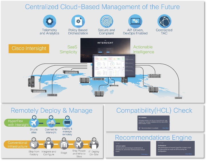
● Consistent infrastructure configuration: Cisco Intersight and UCS help bring up the entire server farm with standardized methods and consistent configuration tools that helps to improve the compute availability, avoid human configuration errors and achieve higher Return on Investments (ROI). Intersight Integration with OpenShift Assisted Installation method enhances deployment experience without hopping on to multiple management points.
● Isovalent Networking for Kubernetes: Cisco’s cloud-native networking and security solution for Kubernetes built on Cilium and eBPF, designed to provide advanced observability, zero-trust security, and high-performance networking for Kubernetes and multi-cloud environments. It extends beyond traditional CNI (Container Network Interface) by offering deep visibility into workloads, identity-aware networking, and policy enforcement at the kernel level without relying on sidecars or iptables. Through this, Cisco positions Isovalent as a foundation for modern application connectivity and security, helping enterprises securely scale containerized and microservices-based architectures.
● Portworx Enterprise integration with Pure Storage FlashArray: This integration offers a unique platform that combines Portworx’s Kubernetes-native storage and data management with the enterprise-grade performance and reliability of FlashArray. With this integration, Portworx abstracts FlashArray’s block storage into a container-ready, software-defined layer, enabling dynamic provisioning, snapshots, backup, and disaster recovery for stateful Kubernetes workloads. FlashArray provides consistent low-latency storage, while Portworx adds capabilities like multi-cloud portability, encryption, and application-level policies—together ensuring scalable, highly available, and production-ready data services for cloud-native applications.
● Splunk Observability Cloud is a SaaS-based, full-stack observability platform that unifies metrics, logs, traces, real user monitoring, and synthetic testing into a single solution for modern, distributed applications. Built on OpenTelemetry and designed for real-time, full-fidelity data ingestion, it helps DevOps, SRE, and IT teams quickly detect, investigate, and resolve issues across infrastructure, applications, and end-user experiences. Its key benefits include faster root cause analysis with AI-driven insights, reduced downtime through proactive alerting, seamless integration with Splunk logs, and improved visibility across hybrid and multi-cloud environments—ultimately driving better performance, reliability, and customer experience.
In addition to the compute-specific hardware and software innovations, integration of the Cisco Intersight cloud platform with Pure Storage FlashArray and Cisco Nexus delivers monitoring, orchestration, and workload optimization capabilities for different layers of the FlashStack solution.
If you are interested in understanding the FlashStack design and deployment details, including configuration of various elements of design and associated best practices, refer to the Cisco Validated Designs for FlashStack here: https://www.cisco.com/c/en/us/solutions/design-zone/data-center-design-guides/data-center-design-guides-all.html#FlashStack
Note: This document serves as the design and deployment guide for the solution.
This chapter contains the following:
● Audience
The FlashStack solution with Red Hat OpenShift on a Cisco UCS Bare Metal configuration represents a cohesive and flexible infrastructure solution that combines computing hardware, networking, and storage resources into a single, integrated architecture. Designed as a collaborative effort between Cisco and Pure Storage, this converged infrastructure platform is engineered to deliver high levels of efficiency, scalability, and performance, suitable for a multitude of data center workloads. By standardizing on a validated design, organizations can accelerate deployment, reduce operational complexities, and confidently scale their IT operations to meet evolving business demands. The FlashStack architecture leverages Cisco's Unified Computing System (Cisco UCS) servers, Cisco Nexus networking, Pure’s innovative storage systems, and Isovalent Enterprise Platform, providing a robust foundation for containerized, virtualized, and non-virtualized environments.
The intended audience for this document includes, but is not limited to IT architects, sales engineers, field consultants, professional services, NetOps teams, K8s Platform teams, Cloud Native teams, IT managers, IT engineers, partners, and customers who are interested to take the advantage of an infrastructure built to deliver IT efficiency and enable IT innovation.
This document provides deployment guidance for bringing up the FlashStack solution with Red Hat OpenShift container and virtualization platforms on Bare Metal Infrastructure. This document introduces various design elements and explains various considerations and best practices for a successful Red Hat OpenShift deployment.
The highlights of this solution are:
● Red Hat OpenShift Bare Metal deployment on FlashStack solution enabling customers to run both containerized and virtualized workloads running alongside each other within a cluster.
● Cisco UCS AMD M8 series servers, powered by the latest AMD EPYC processors, offers higher compute, memory densities for hosting modern enterprise workloads and AI-Ready design to support required GPUs for running AI/ML based workloads. Additionally, boot from SAN storage (Fiber Channel) provides several benefits including stateless and simplified computing, rapid provisioning of the compute nodes and integration with enterprise grade storage features like clones, backup, snapshots, replication etc. for faster backup and recovery of boot volumes.
● This OpenShift solution utilizes Isovalent Enterprise as Container Networking Interface (CNI) framework offering high performing networking, security, policy enforcement, and observability by leveraging Extended Berkeley Packet Filter (eBPF) technology.
● With the latest Portworx Enterprise brings in support for ReadWriteMany (RWX) raw block volumes for KubeVirt virtual machines (VMs), enabling high-performance, shared storage configurations that support live migration of VMs in OpenShift environments. PX-Backup offers a data protection solution that provides application-consistent backup, restore, and disaster recovery for containerized and virtualized workloads across on-premises and cloud environments. The solution uses Pure Storage FlashArray as backend storage for Portworx which is a truly unified block, file, and object storage that continues to get faster, more reliable, more secure, smarter, and easier to manage over time. Upgrades are always with data-in-place and completely non-disruptively—without caveats or compromise.
● Splunk Observability Cloud is a SaaS-based, full-stack observability platform designed for modern, distributed environments. It brings together the three pillars of observability—metrics, logs, and traces—into a unified interface, enabling teams to quickly detect, troubleshoot, and resolve issues across applications, infrastructure, and digital experiences.
This chapter contains the following:
● Cisco UCS AMD M8 Series Servers and Cisco Intersight
● Isovalent Networking for Kubernetes
● Portworx Enterprise with Red Hat OpenShift Virtualization
● Portworx Enterprise with Pure Storage FlashArray
● Data Protection with PX-Backup and Pure Storage FlashBlade
● Infrastructure and Application Monitoring with Splunk Observability
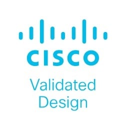
The FlashStack architecture was jointly developed by Cisco and Pure Storage. All FlashStack components are integrated, allowing you to deploy the solution quickly and economically while eliminating many of the risks associated with researching, designing, building, and deploying similar solutions from the foundation. One of the main benefits of FlashStack is its ability to maintain consistency at scale. Figure 1 illustrates the series of hardware components used for building the FlashStack architectures. Each of the component families (Cisco UCS, Cisco Nexus, Cisco MDS, Portworx by Pure Storage and Pure Storage FlashArray systems) offers platform and resource options to scale-up or scale-out the infrastructure while supporting the same features and functions.
Go to the Appendix for more information about the components used in this solution.
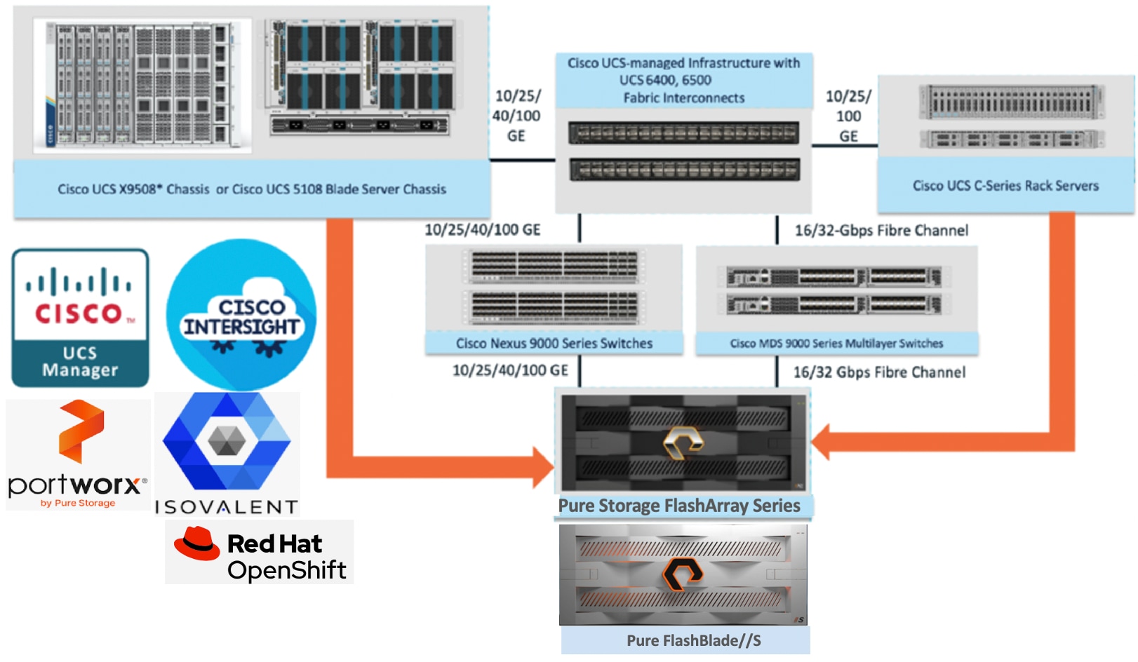
Red Hat OpenShift is a family of containerization software products developed by Red Hat. Red Hat OpenShift Container Platform (OCP) is its flagship product that is Kubernetes-based enterprise container platform helps organizations build, deploy, and manage applications consistently across hybrid and multi-cloud environments. It is built on open-source Kubernetes but adds enterprise features like enhanced security, developer productivity tools, built-in CI/CD pipelines, and centralized management.
Red Hat OpenShift Virtualization is an add-on feature of OpenShift that lets us run and manage virtual machines (VMs) side by side with containers on the same OpenShift cluster. It uses the open-source KubeVirt project to extend Kubernetes APIs for VM lifecycle management so that you can create, start, stop, migrate, scale VMs through the OpenShift console or oc CLI. It leverages KVM, QEMU and few other libraries like libvirt, virt_launcher, Multus CNI, OVN-K etc. to provide a reliable type-1 hypervisor for virtualization tasks. It leverages CNI for VM networking and CSI for the persistent storage. It uses OpenShift security features such as SCCs, RBAC, and SELinux for VM isolation. When Red Hat OpenShift Virtualization is added to a Red Hat OpenShift environment, both containers and VMs can now be run side-by-side on the same infrastructure as shown in Figure 2.
Cisco UCS AMD M8 Series Servers and Cisco Intersight
Cisco UCS AMD M8 Series Servers use 4th-and 5th-gen AMD EPYC CPUs which offer large numbers of cores per socket. This gives high aggregate compute power and larger memory capacity offering high performance for multi-threaded workloads, virtualization, big data, analytics. Cisco UCS X215c M8 and C245 M8 offer dual socket configurations with DDR5 memory DIMMS (operating at high speeds 4800 MTs to 6000 MTs) for higher compute, better memory capacity, and bandwidth. Cisco UCS C225 M8 offers single socket configuration simplifying the configurations (no NUMA complications), reduce the costs but achieving high core counts and I/O. These servers also support multiple GPU options offering dense GPU-compute per rack useful for scale out workloads like analytics and AI/ML workloads. With Cisco UCS 5th generation VIC cards, these servers offer unified fabric for consolidating various traffics, high speed networking, agile infrastructure with virtualization feature, and simplified Management.
Cisco Intersight is a lifecycle management platform for your infrastructure, regardless of where it resides. In your enterprise data center, at the edge, in remote and branch offices, at retail and industrial sites—all these locations present unique management challenges and have typically required separate tools. Cisco Intersight Software as a Service (SaaS) unifies and simplifies your experience of the Cisco Unified Computing System (Cisco UCS). In addition to the Cisco UCS management, Cisco switches, and Pure Storage FlashArray are also integrated into the Cisco Intersight. With this integration, FlashArray storage controllers can be managed and perform all day one management tasks, and these tasks can be incorporated into the Intersight workflows.
Isovalent Networking for Kubernetes
Isovalent Networking for Kubernetes is available and supported across several Kubernetes platforms and offerings. One of the most popular is that of Red Hat OpenShift. Red Hat OpenShift provides a default networking model leveraging Open Virtual Network (OVN) which internally uses Open Virtual Switch (OVS). When business-critical applications are migrated to OpenShift, there is an increased need for a cloud native networking approach. Identity- and application-aware policy enforcement become standard requirements. Isovalent Networking for Kubernetes leverages eBPF (extended Berkeley Packet Filter) to address these needs, providing high-performance networking, robust security, and deep observability directly within the Kubernetes environment.
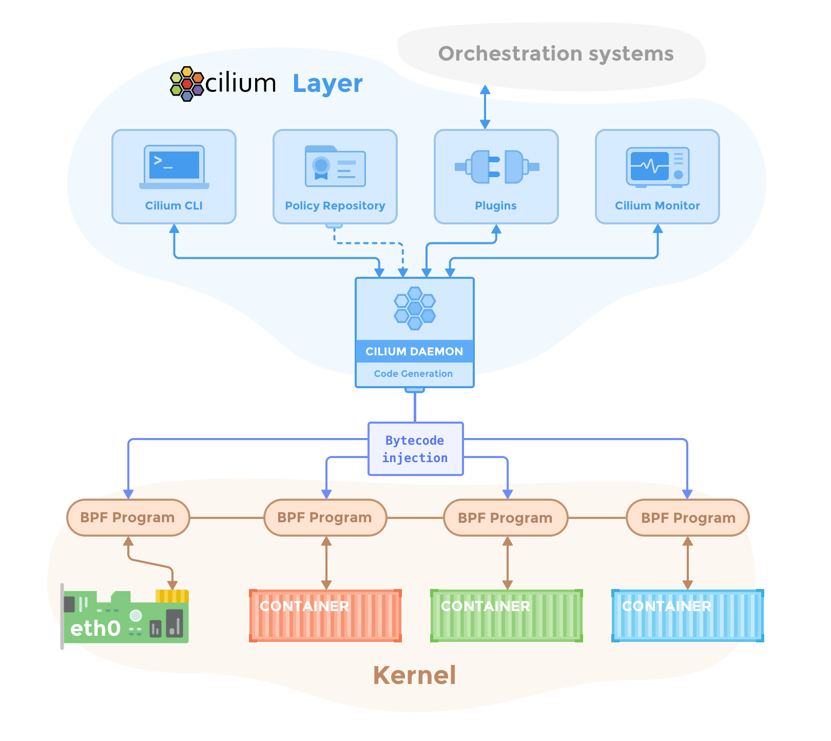
Isovalent's platform, built on the open-source Cilium project, utilizes eBPF technology to embed networking and security logic directly into the Linux kernel, offering an innovative approach to managing containerized environments. This enables capabilities such as L3/L4 and L7-aware network policy enforcement, identity-based security, zero-trust networking, and transparent encryption. Furthermore, it provides extensive observability through tools like Hubble, offering cluster-wide flow visibility and identity-aware network metrics. Designed for Kubernetes environments, including being certified for Red Hat OpenShift, Isovalent Enterprise for Cilium ensures optimal scale, performance, and compliance across cloud and on-prem infrastructure.
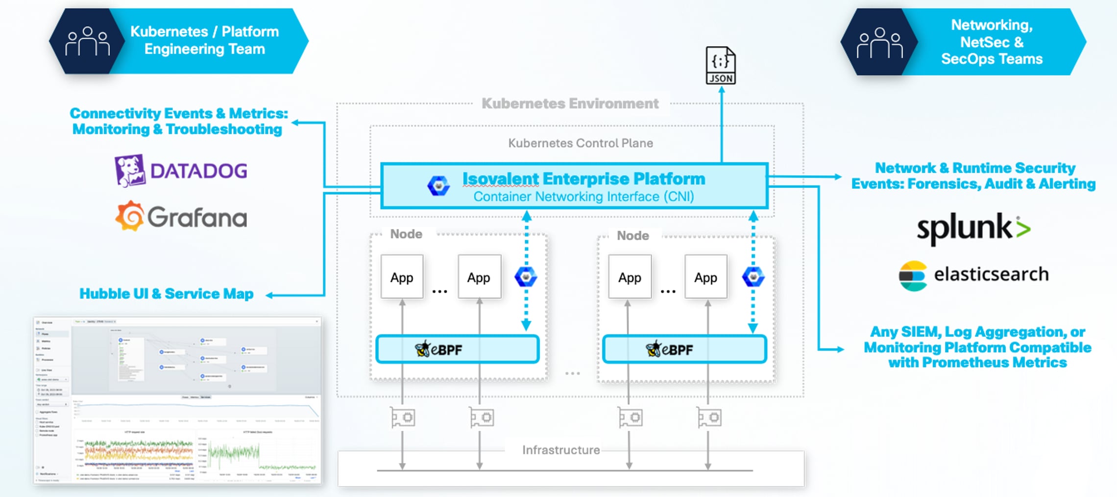
By using an eBPF based implementation, the default, iptables-based OpenShift provided CNI can be replaced with a dataplane that executes directly within the Linux kernel. The above enhanced capabilities are provided as part of the wider cloud native platform offering, in this case, Red Hat OpenShift, whilst avoiding the resource overheads associated with other typical cloud native networking implementation models. As a certified Operator, the solution integrates with OpenShift's Cluster Network Operator (CNO) for deployment and lifecycle management from the OpenShift console.
The eBPF data plane’s kernel-level operation provides performance advantages over iptables. By using eBPF maps for lookups instead of traversing linear iptables rule chains, it processes network traffic with lower CPU overhead and reduced latency. eBPF programs handle packet forwarding, policy enforcement, and telemetry collection within the kernel, which eliminates context switches between user and kernel modes.
For FlashStack deployments with Red Hat OpenShift, Isovalent Networking for Kubernetes provides a highly flexible overlay networking model using VXLAN encapsulation. This mode, which is the default, simplifies deployment by creating a virtual network that spans all cluster nodes, requiring minimal configuration on the underlying physical network fabric. The container network is decoupled from the physical infrastructure, allowing OpenShift nodes to span multiple L2 or L3 domains without complex fabric configurations. While the VXLAN overlay offers maximum flexibility, a native routing underlay model using Border Gateway Protocol (BGP) is also supported for use cases requiring direct fabric integration and the elimination of encapsulation overhead.
General Architectural Benefits of Isovalent Networking for Kubernetes
● EBPF-based Data Plane Performance: The eBPF data plane provides performance improvements over iptables-based CNIs by processing packets in the kernel. This reduces CPU overhead and network latency by using efficient map-based lookups instead of linear rule chain processing and by eliminating kernel-to-userspace context switches for packet forwarding and policy enforcement.
● Identity-Based Security Model: The security model is based on workload identity derived from Kubernetes labels, rather than ephemeral IP addresses. Policies are enforced by eBPF in the kernel for L3/L4 traffic.
● Integrated Network Observability: The architecture includes Hubble or Hubble Timescape (for future releases of Isovalent), an observability platform that uses the same eBPF data source to provide visibility into network flows, service dependencies, and policy enforcement without requiring separate agents.
● Flexible Networking Models: The CNI supports multiple networking modes, including an overlay model using VXLAN for deployment flexibility and an underlay model using BGP for native routing performance.
Benefits of FlashStack with OpenShift Environments
● Optimized Resource Utilization on UCS Compute: The CPU cycle reduction from the eBPF data plane frees compute resources on Cisco UCS X-Series nodes, allowing more capacity to be allocated to application workloads. This efficiency applies to complex server configurations, including those with multiple vNICs, without the need to manage iptables rules for each interface.
● Flexible Overlay Networking with VXLAN: Cilium’s default VXLAN overlay mode provides significant operational simplicity for FlashStack deployments. It establishes a virtual network fabric on top of the existing Cisco Nexus infrastructure, requiring only standard IP connectivity between nodes. This decouples the lifecycle and management of the container network from the physical network, allowing for greater agility. Pod-to-pod traffic is encapsulated, meaning the physical network does not need to be aware of pod IP addresses. The VXLAN header can also carry metadata, which Cilium uses to transmit security identity information, optimizing policy enforcement between nodes.
● XDP Acceleration and Hardware Offload Readiness: The solution supports eXpress Data Path (XDP) to accelerate services like NodePort and LoadBalancer by processing packets at the network driver layer. The eBPF architecture is also suited for future offloading to Data Processing Units (DPUs) and SmartNICs, a capability that aligns with the evolution of Cisco's hardware portfolio (upcoming capabilities).
● Resilient Fabric Integration: The BGP implementation supports the high-availability design of the FlashStack fabric, which includes redundant Cisco UCS Fabric Interconnects and Nexus switches. It enables routing topologies that can reconverge in the event of a link or switch failure, maintaining network connectivity for applications by rerouting traffic through available paths.
Isovalent Networking for Kubernetes Deployment in OpenShift
Isovalent Networking for OpenShift can be deployed in the following methods:
● Base Installation: In this method, the Isovalent is deployed when OpenShift cluster is being provisioned (commonly referred to as “bootstrap”). The installation of Isovalent Networking for Kubernetes varies depending on how the OpenShift cluster is being provisioned. Isovalent can be installed with OpenShift Installer binary (Agent-based Installer, Installer-Provisioned Infrastructure, User-Provisioned Infrastructure) and with Red Hat Advanced Cluster Management (RHACM) and with Red Hat OpenShift Container Platform with hosted control planes (HCP).
● Migrating to Isovalent Networking for Kubernetes: Isovalent can also be installed after the OpenShift cluster is being provisioned by migrating the default OVN-K CNI plugin to Isovalent.
In this FlashStack validation, Isovalent is used as CNI plugin for providing OpenShift networking. This is achieved by migrating the default OpenShift OVN CNI plugin to Isovalent Networking for Kubernetes.
The following sections provide the steps for migrating to Isovalent Networking for Kubernetes in an existing OpenShift cluster.
Note: For this CVD validation, to cover both new and existing FlashStack deployments, the process of OVN migration to Isovalent has been chosen. This migration process from OVN to Isovalent Enterprise can be utilized for both green and brown field environments.
Portworx Enterprise with Red Hat OpenShift Virtualization
Portworx delivers integrated, enterprise-grade storage for VMs and containers, simplifying operations through Kubernetes while providing high availability, cross-site resiliency, advanced (sync/async) disaster recovery, automated scaling, and strong data security. With STORK, you gain VM migration between clusters plus policy-driven backup and restore to meet SLA commitments. This integration supports a unified infrastructure where traditional and cloud-native workloads coexist, offering flexible deployment across diverse environments. For more information, go to the Appendix.
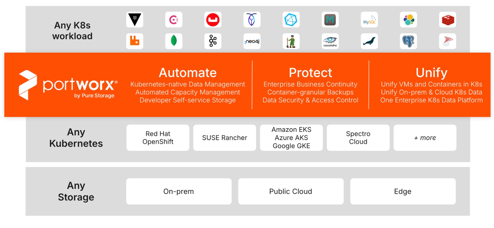
Portworx by Pure Storage unlocks the value of Kubernetes data at enterprise scale. It’s a fully integrated container data platform that Automates, Protects, and Unifies modern applications across hybrid and multi-cloud, works with any underlying storage (on-prem or cloud) and any Kubernetes distribution, and simplifies developer actions and platform data management.
● Automate: Portworx automates Kubernetes data management end-to-end, boosting efficiency and time-to-market across DevOps/MLOps. It abstracts heterogeneous on-prem/cloud storage and delivers a cloud operating model with self-service storage/database services.
● Protect: Architect app-aware resiliency from Day 1 with synchronous DR (zero-data-loss targets) and automated Day-2 operations. Encrypt at cluster or storage-class scope, enforce RBAC, and use policy-driven backups with immutability/portability to counter ransomware.
● Unify: Unify Kubernetes storage by removing per-array CSI dependencies so platforms stay fully declarative across hybrid/multi-cloud. Manage data for containers and VMs in one solution—reducing VM licensing overhead and preserving future flexibility.
Portworx with Red Hat OpenShift Virtualization and KubeVirt enhances data management for virtual machines and containers by offering integrated, enterprise-grade storage. Includes simplified storage operations through Kubernetes, high availability and resiliency across environments, advanced disaster recovery options, and automated scaling capabilities. This integration supports a unified infrastructure where traditional and modern workloads coexist, providing flexibility in deployment across diverse infrastructures and ensuring robust data security. Portworx and Stork offers capabilities like VM migration between clusters, Synchronous Disaster Recovery, Ability to backup and restore VMs running on Red Hat OpenShift to comply with the service level agreements.
Figure 6 shows the suite of products that Portworx offers as of today. For more information on these products, go to the Appendix.
This solution is validated with Portworx version 3.4, which offers following additional benefits alongside its established enterprise-grade storage features, including replication, snapshots, clones, compression, and encryption.
● Shared ReadWriteMany (RWX) Block volumes for KubeVirt VMs: Portworx supports RWX raw block volumes for KubeVirt virtual machines (VMs) enabling high-performance, shared storage configurations that is required to support live migration of VMs in the OpenShift environments.
● DR support for KubeVirt VMs with Portworx RWX Block Volumes: Portworx supports synchronous and asynchronous disaster recovery on KubeVirt virtual machines (VMs) with ReadWriteMany (RWX) raw block volumes running on OpenShift Virtualization version 4.18.5 or later and OpenShift Container Platform version 4.18.x.
● Application I/O Control: Portworx supports Application I/O Control on hosts that use cgroup v2, in addition to cgroup v1. Portworx automatically detects the available cgroup version and applies I/O throttling accordingly to ensure seamless operation across supported Linux distributions. This feature becomes handy to prevent a "noisy neighbor" problem by setting IOPS (input/output operations per second) and bandwidth limits for individual persistent volumes in a shared storage pool.
● FlashArray Direct Access (FADA) Shared Block Devices: Portworx enables the seamless integration of KubeVirt virtual machines (VMs) within Kubernetes clusters, leveraging the high performance of ReadWriteMany (RWX) volumes backed by FlashArray Direct Access (FADA) shared raw block RWX volumes. This approach supports raw block devices, which provide direct block storage access instead of a mounted filesystem. This is particularly beneficial for applications that demand low-latency and high-performance storage.
Portworx Enterprise with Pure Storage FlashArray
Portworx on FlashArray offers flexible storage deployment options for Kubernetes. Using FlashArray as cloud drives enables Autopilot-driven automatic volume provisioning, and seamless cluster expansion. Direct Access volumes allow for efficient on-premises storage management, offering file system operations, IOPS, and snapshot capabilities. Multi-tenancy features isolate storage access per user, enhancing security in shared environments.
Portworx on FlashArray enhances Kubernetes environments with robust data reduction, resiliency, simplicity, and support. It lowers storage costs through FlashArray’s deduplication, compression, and thin provisioning, providing 2-10x data reduction. FlashArray’s reliable infrastructure ensures high availability, reducing server-side rebuilds. Portworx simplifies Kubernetes deployment with minimal configuration and end-to-end visibility via Pure1. Additionally, unified support, powered by Pure1 telemetry, offers centralized, proactive assistance for both storage hardware and Kubernetes services, creating an efficient and scalable solution for enterprise needs.
Figure 7 shows the high-level logical storage architecture of Portworx Enterprise deployment with Pure Storage FlashArray as backend storage for the OpenShift cluster.
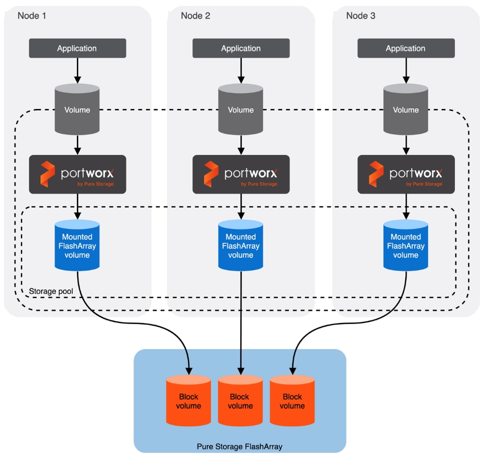
This is the high-level summary of the Portworx Enterprise implementation of distributed storage on a typical Kubernetes based Cluster:
● Portworx Enterprise runs on each worker node as Daemonset pod and based on the configuration information provided in the StorageCluster spec, Portworx Enterprise provisions one or more volumes on Pure Storage FlashArray for each worker node.
● All these Pure Storage FlashArray volumes are pooled together to form one or more Distributed Storage Pools.
● When a PVC requested by the application, Portworx Enterprise provisions the volume from the storage pool.
● The PVCs consume space on the storage pool, and if space begins to run low, Portworx Enterprise can add or expand drive space from Pure Storage FlashArray.
● Portworx is designed to minimize downtime and data unavailability during worker node failures by leveraging storage-level replication and intelligent pod scheduling. Portworx volumes can be configured with multiple replicas, each stored on different worker nodes. This means that if a node fails, other nodes still have up-to-date copies of the data. Also with the help of Stork, Portworx’s scheduler extender can reschedule pods to other nodes that already have a replica of the required volume.
Data Protection with PX-Backup and Pure Storage FlashBlade
PX-Backup is a leading data protection built for any Kubernetes, securing persistent data irrespective of their deployments (on-prem or cloud). It provides enterprise-grade data protection for containerized workloads, and virtual machines hosted on variants of Kubernetes clusters like OpenShift. In this solution, PX-Backup, backed by Pure Storage FlashBlade//S200, is used to back up the various container-based applications as well as virtual machines running on OpenShift cluster. The backups can be easily schedulable based on the RTO/RPO objectives and can be restored seamlessly on to the same or different OpenShift clusters.
Pure Storage FlashBlade//S200 is an all-flash, scale-out unified fast file and object storage solution that is an ideal high-performance and scalable backup target for PX-Backup. Using Pure Storage FlashBlade//S200 with PX-Backup gives Kubernetes environments a blazing-fast, S3-compliant, on-premises backup target that ensures rapid application recovery, high scalability, and enterprise-grade for mission-critical workloads.
Infrastructure and Application Monitoring with Splunk Observability
Splunk Observability is Splunk’s cloud-based platform for full-stack observability, helping organizations monitor, troubleshoot, and optimize the performance of applications, infrastructure, and user experiences in real time. It combines metrics, traces, logs, and events into a single platform so teams can quickly detect issues and improve reliability.
Explore the benefits of Splunk Infrastructure Monitoring, Splunk APM, Splunk RUM, Splunk Synthetic Monitoring and Splunk Log Observer Connect, all in one interface (one user seat):
● Easily detect potential issues and identify root causes using high-resolution, streaming analytics.
● Instantly see how every user experiences your app and how each code change impacts site performance.
● Keep total control over your data with no vendor lock-in and OpenTelemetry — instrument once, observe everywhere.
This chapter contains the following:
● FlashStack Physical Topology
● Red Hat OpenShift Cluster on Bare Metal Server Configuration
● OpenShift Networking and VM Networking
FlashStack with Cisco UCS and Cisco Intersight meets the following design requirements:
● Resilient design across all the layers of infrastructure with no single point of failure
● Scalable design with the flexibility to add compute capacity, storage, or network bandwidth as needed
● Modular design that can be replicated to expand and grow as the needs of the business grow
● Flexible design that can support different models of various components with ease
● Simplified design with the ability to integrate and automate with external automation tools
● AI-Ready design to support required NVIDIA GPUs for running AI/ML based workloads
● Cloud-enabled design which can be configured, managed, and orchestrated from the cloud using GUI or APIs
● Unified full-stack visibility for real-time monitoring, faster troubleshooting, and improved digital resilience by correlating metrics, logs, and traces across infrastructure and applications
To deliver a solution meets all these design requirements, various solution components are connected and configured as explained in later sections.
This CVD details the Red Hat OpenShift Bare Metal deployments built over FC and Ethernet-based FlashStack designs using the latest Cisco UCS AMD M8 series servers. Cisco Nexus 93699CD-GX switches are used to provide the IP storage connectivity between the servers and storage using TCP/IP protocol while Cisco MDS 9132T switches are used for providing storage access using Fibre Channel protocol. The physical components and connectivity details are covered below.
Figure 8 shows the two physical topologies and network connections used for this Ethernet and Fibre Channel-based FlashStack designs.
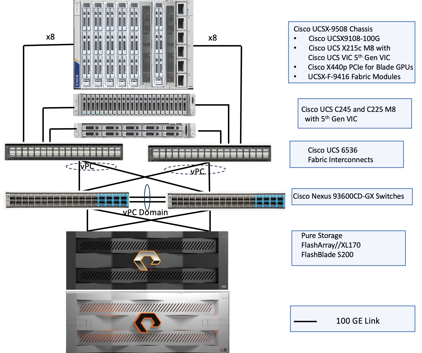
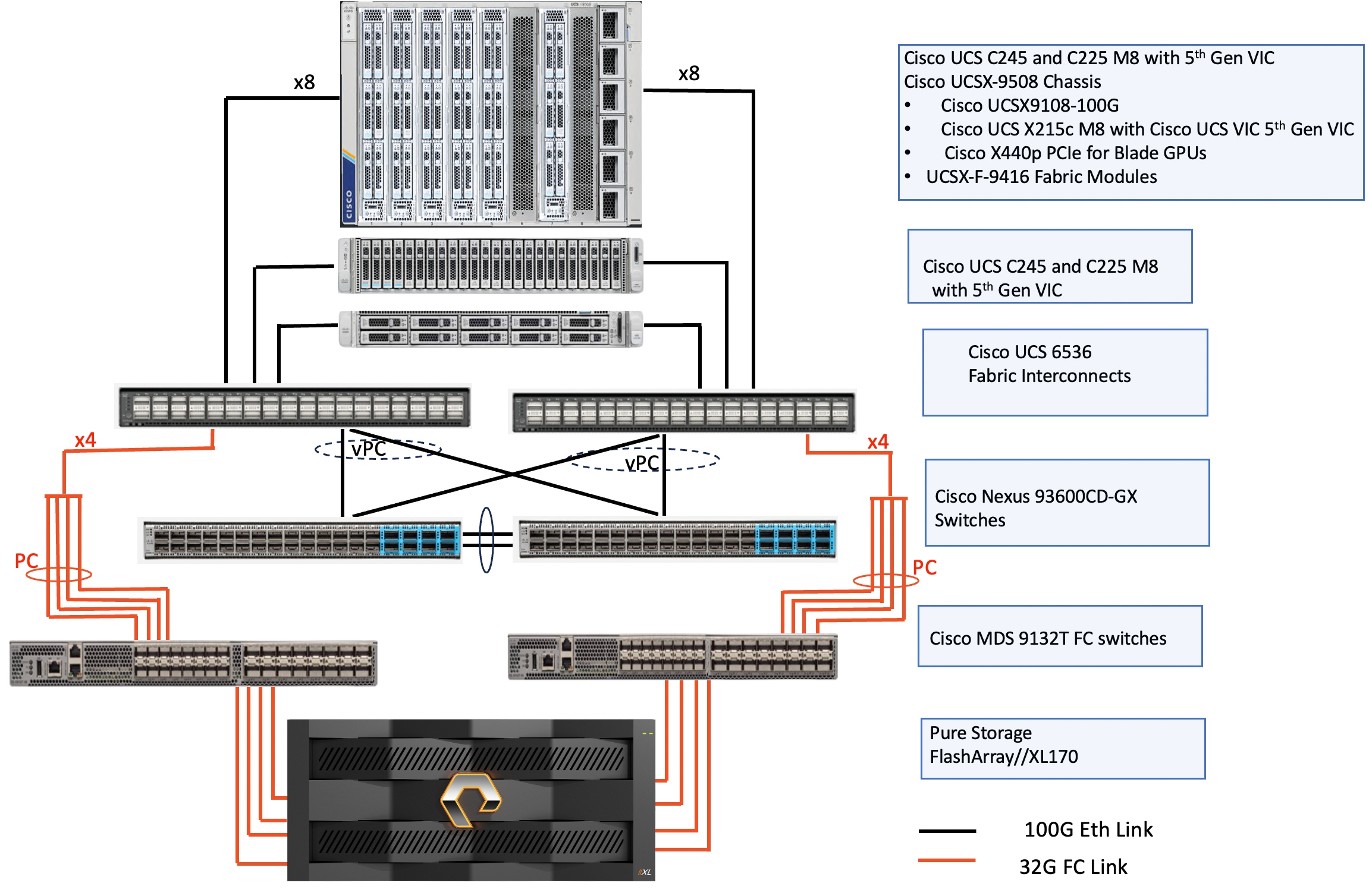
The reference hardware configuration includes:
● Cisco UCS X9508 chassis, equipped with a pair of Cisco UCS X9108 100G IFMs, contains six Cisco UCS X215c M8 compute nodes and two Cisco UCS X440p PCIe nodes each with couple of NVDIA L40S and H100 NVL GPUs. Other configurations of servers with and without GPUs are also supported. Each compute node is equipped with fifth-generation Cisco UCS VIC card 15231 providing 100-G ethernet connectivity on each side of the fabric. A pair of Fabric Modules installed at the rear side of the chassis enables connectivity between the X440p PCIe nodes and X215c M8 nodes. Cisco VIC is configured with required vNICs and vHBAs for enabling network as well as storage access (using iSCSI, NVMe-TCP and FC protocols).
● Cisco UCS Cisco UCS C245 and C225 M8 C-Series servers also validated for this solution. UCS C245 M8 is a dual socket server that support up to 24 memory DIMMs. These servers are ideal for cpu-intensive and memory-intensive workloads that benefit from dual-CPU configurations. On the other hand, UCS C225 M8 is a single socket server supporting highest core AMD CPUs (up to 160 Cores) with plenty of PCIe slots for additional I/O expansion. Both C245 and C225 servers are equipped with UCS 5th Gen VIC 15237 dual port 40/100Gbps mLOM network card. Cisco VIC is configured with required vNICs and vHBAs for enabling network as well as storage access (using iSCSI, NVMe-TCP and FC protocols).
● Cisco fifth-generation 6536 Fabric Interconnects (FIs) are used to provide connectivity to the compute nodes installed in the chassis. These FIs are configured in End-Host mode acting like a host (not a traditional switch) to the upstream network, optimizing traffic flow and simplifying network management. The Unified ports (33 to 36) on each FI can be breakout into four 8/16/32 Gbps Fibre Channel connections per port. In case FC-based FlashStack deployment, breakout cables are required to connect FIs and MDS for Fibre Channel storage access.
● A pair of Nexus C93600CD-GX switches are used in Virtual Port Channel (vPC) mode. This high-speed Cisco NXOS-based Nexus C93600CD-GX switching design supports up to 100 and 400-GE connectivity.
● A pair of Cisco MDS 9132T Fibre Channel switches are used for providing storage access to the compute nodes using Fibre Channel protocol. Cisco MDS 9132T is a 32-Gbps 32-Port Fibre Channel Switch and is a powerful and compact 1-rack unit (1RU) SAN fabric switch.
● The Pure Storage FlashArray //XL170 is a high-performance, all-flash storage array designed for mission-critical enterprise workloads. It is part of Pure Storage’s FlashArray //XL family, aimed at delivering extreme performance, high availability, and scalability for demanding applications such as databases, virtualization, analytics, and large-scale consolidations. In this solution, FlashArray//XL170 is used as backend storage for Portworx that provides persistent storage for both containers and virtual machines hosted on the OpenShift cluster. The storage array controllers are connected Nexus switches using 100Gbps network cards for storage access over iSCSI/NVMe-TCP protocols. For FC-based deployments, each controller needs to be connected to MDS switches as shown in the above figure.
● The FlashBlade S200 is a next-generation unified fast file and object storage platform from Pure Storage, designed for high-performance workloads such as modern analytics, AI/ML, rapid backup and recovery, and large-scale unstructured data management. This unified storage supports both file (NFS, SMB) and object (S3 compliant) protocols within a single platform. In this solution, FlashBlade S200 is used as S3 compliant back end storage for PX backup which provides consistent data protection for the pods and virtual machines hosted on the OpenShift cluster. The FIOMs of FlashBlade are connected to the Nexus switches to provide S3 compatible object storage to the cluster over ethernet for backup/restore of application Pods/VMs hosted on the OpenShift cluster.
Note: Additional 1Gb management connections are needed for one or more out-of-band network switches that are apart from the FlashStack infrastructure. Each Cisco UCS C-Series server, fabric interconnect and Cisco Nexus switch is connected to the out-of-band network switches, Pure Storage FlashArray controllers and FlashBlade//S200 have connections to the out-of-band network switches. Layer 3 network connectivity is required between the Out-of-Band (OOB) and In-Band (IB) Management Subnets.
The software components consist of:
● Cisco Intersight platform to deploy, maintain, and support the FlashStack components.
● Cisco Intersight Assist virtual appliance to help connect the Pure Storage FlashArray and Cisco Nexus Switches with the Cisco Intersight platform to enable visibility into these platforms from Intersight.
● Red Hat OpenShift Container Platform for providing a consistent hybrid cloud foundation for building and scaling containerized and virtualized applications.
● Isovalent Networking for Kubernetes replaces the default OVN. The seamless integration of Isovalent with OpenShift enables Isovalent to provide advanced eBPF-powered networking, security, and observability for containerized applications, offering high performance, zero-trust network policies, and a unified CNI and service mesh.
● Portworx by Pure Storage (Portworx Enterprise) data platform for providing enterprise grade storage for containerized and virtualized workloads hosted on OpenShift platform.
● PX-Backup for data protection of container based applications and virtual machines hosed on the Red Hat OpenShift cluster.
● Pure Storage Pure1 is a cloud-based, AI-driven SaaS platform that simplifies and optimizes data storage management for Pure Storage arrays, offering features like proactive monitoring, predictive analytics, and automated tasks.
The information in this section is provided as a reference for cabling the physical equipment in a FlashStack environment.
The compute infrastructure in FlashStack solution consists of the following:
● Cisco UCS X215c M8 Compute Nodes
● Cisco UCSC-C245-M8SX and UCSC-C225-M8N
● Cisco UCS X-Series Chassis (Cisco UCSX-9508) with Intelligent Fabric Modules (Cisco UCSX-I-9108-100G)
● Cisco UCS Fabric Interconnects (Cisco UCS-FI-6536)
● Cisco Nexus 93600CD-GX Ethernet switches
● Cisco MDS 9132T Fibre Channel Switches
The Cisco UCS X9508 Chassis is equipped with the Cisco UCS X9108-100G intelligent fabric modules (IFMs). The Cisco UCS X9508 Chassis connects to each Cisco UCS 6536 FI using four 100GE ports, as shown in Figure 10. If you require more bandwidth, all eight ports on the IFMs can be connected to each FI.
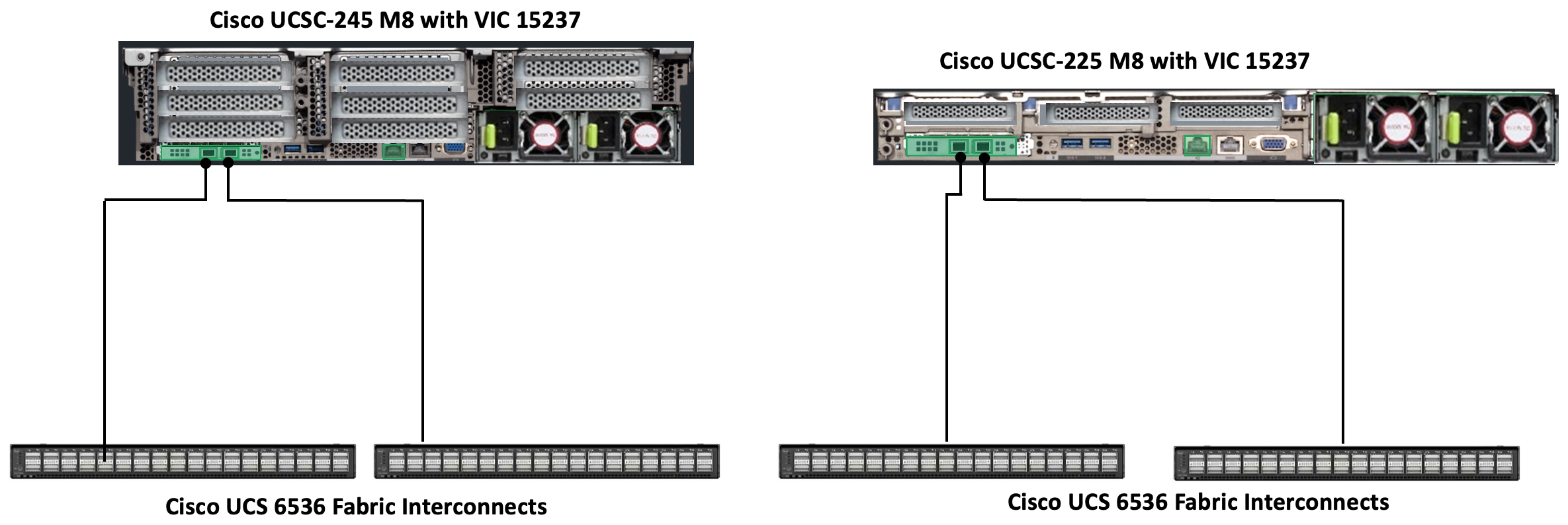
Cisco UCS C245 and C225 M8 C-Series servers are equipped with Cisco UCS 5th Gen VIC 15237 dual port 40/100Gbps mLOM network card. Each C-Series server is connected to Cisco UCS 6536 FIs using two 100GE ports as shown in Figure 11.

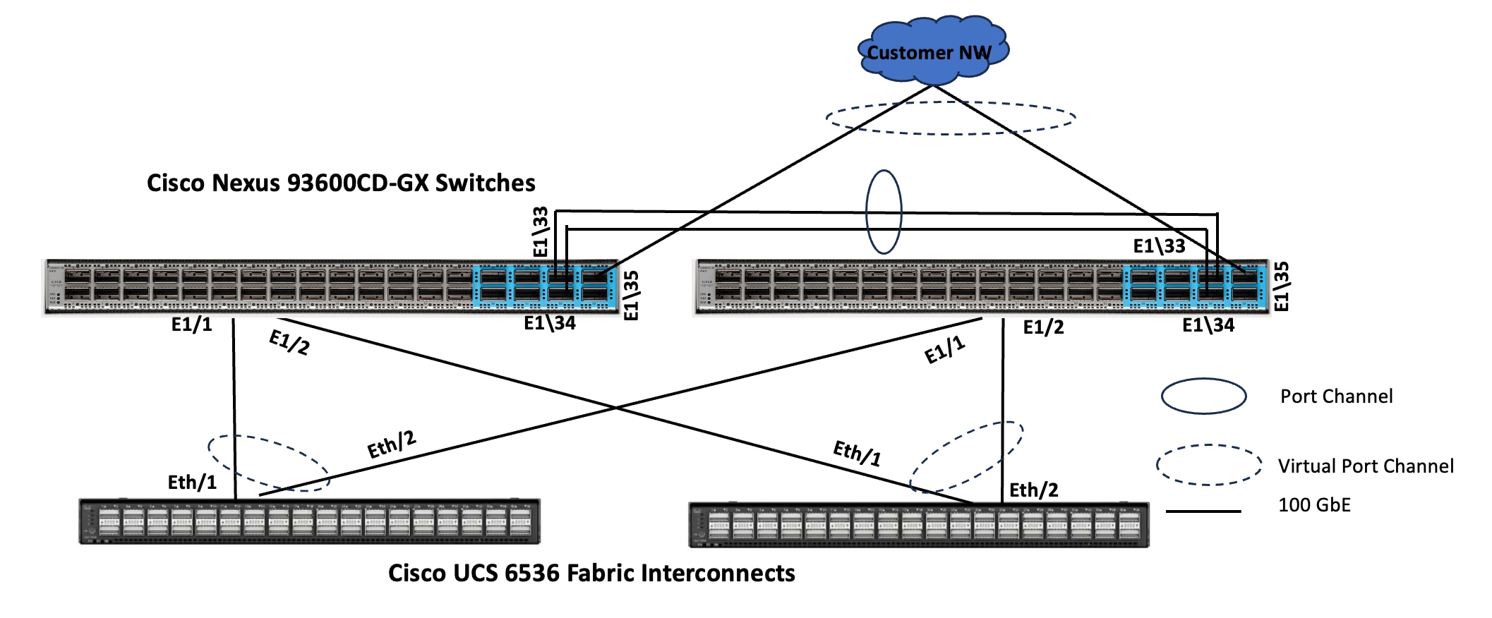
Compute UCS Fabric Interconnect 6536 Connectivity
Cisco UCS 6536 FIs are connected to Cisco Nexus 93600CD-GX switches using 100GE connections configured as virtual port channels. Each FI is connected to both Cisco Nexus switches using a 100G connections; additional links can easily be added to the port channel to increase the bandwidth as needed. Figure 12 illustrates the physical connectivity details.
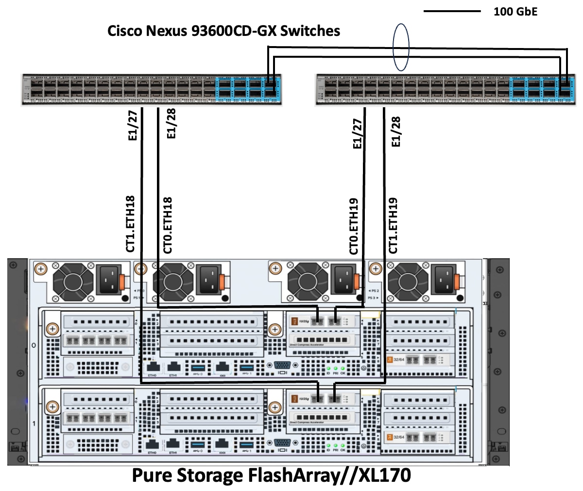
Pure Storage FlashArray//XL170 Ethernet Connectivity
Pure Storage FlashArray controllers are connected to Cisco Nexus 93600CD-GX switches using redundant 100-GE. Figure 13 illustrates the physical connectivity details.
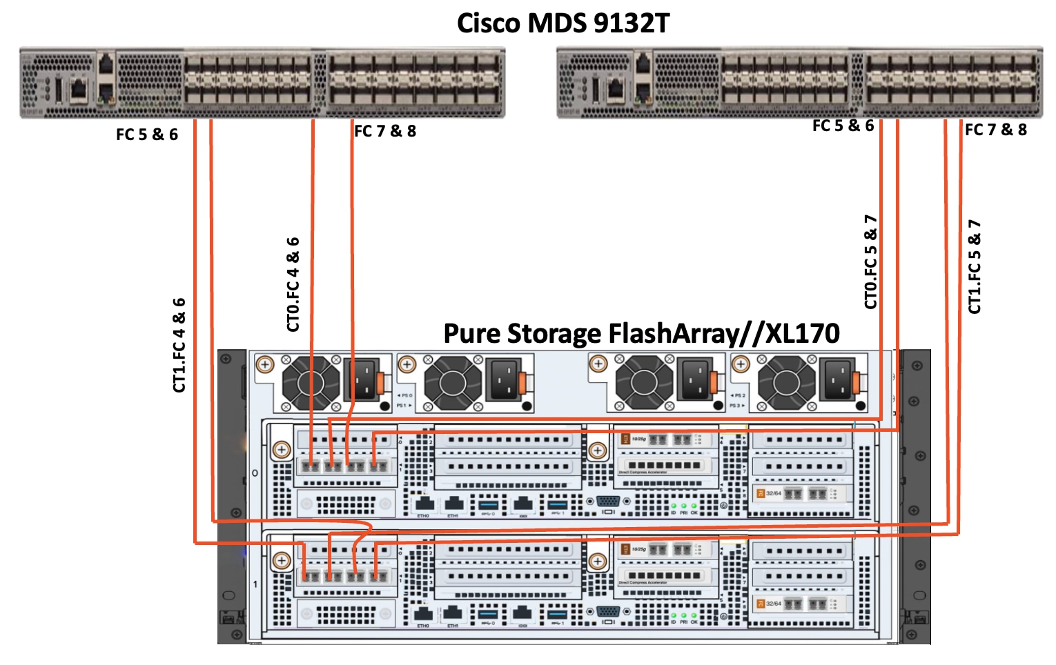
Pure Storage FlashArray//XL170 Fibre Channel Connectivity
Pure Storage FlashArray controller are connected to Cisco MDS 9132T Fibre Channel switches using redundant 32Gbps fibre channel cables as shown in Figure 14.
Pure Storage FlashBlade//S200 Ethernet Connectivity
Pure Storage FlashBlade uplink ports (2x 100GbE from each FIOM) are connected to Cisco Nexus 93600CD-GX switches as shown in the below figure. Additional links can easily be added (up to 8x 100GbE on each FIOM) to the port channel to increase the bandwidth as needed. Figure 15 illustrates the physical connectivity details.
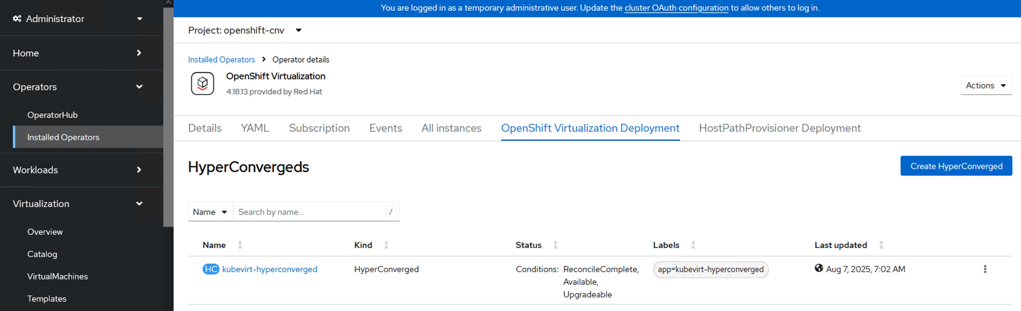
Figure 16 details the cable connections used in the validation lab for the FlashStack topology based on the 5th Generation Cisco UCS 6536 Fabric Interconnects.
On each Fabric Interconnect, E1/3 and E1/4 ports are configured as Server ports for discovering and managing the UCS X9508 chassis through UCS 9108 100G IFMs. on each FI, five 100G ports ( from 7 to 11) are as Server Ports for connecting and managing UCS C-Series servers. E1/1 and E1/2 ports on each FI are configured as Ethernet Uplink ports and connected to the pair of Cisco Nexus 93600CD-GX switches that are configured with a vpc domain. On each side of fabric, one breakout cable is used to connect FI (from Port 36) and MDS switch. Pure Storage FlashArray//Xl170 and FlashBlade//S200 arrays are also connected to the pair of Nexus 93600CD-GX switches over 100G ports. Similarly, each FlashArray controller is connected to pair of MDS switches using 4x 32Gbps FC ports. As mentioned earlier, Additional 1Gbps network ( not shown in the figure) is required for Out of Band management connectivity.
Red Hat OpenShift Cluster on Bare Metal Server Configuration
A simple Red Hat OpenShift cluster consists of at least five servers – Control Plane Nodes and two or more Worker compute nodes where applications and VMs are run. The control plane nodes require less cpu and memory resources compared to worker nodes, and the resource requirements depend on the number of worker nodes in the OpenShift cluster. Hence, for dedicated control-plane deployments, low end servers (configured with low end cpu and memory configs) can be used.
Note: In this lab validation, a total of three control plane nodes and four Worker Nodes are configured using both Cisco UCS X-Series and C-Series servers. Another worker node (eighth node) will be added to the cluster as part of cluster expansion. The CPU and memory resources available on these nodes are higher than Red Hat recommended values for control plane nodes. Therefore, the three control plane nodes are also configured as worker nodes to run the workloads
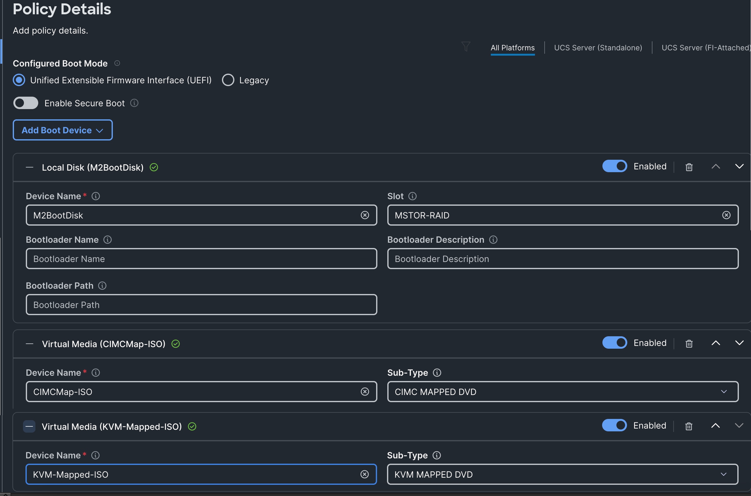
In IP-based FlashStack design, each Node is booted from RAID1 disk created using two M.2 SSD drives. In the absence of M.2 cards, the front-loaded disks, in RAID 1 configuration, can also be used for OS installation. In FC-Based design, all the nodes are configured to boot from SAN using Fibre Channel protocol. Required vHBAs created in the Server profile and a separate boot order policy is used for booting the servers from SAN. UCS X440p PCIe Nodes provides PCIe expansion for UCS X-Series compute nodes. NVIDIA L40S and H100 NVL GPUs are installed X440p nodes and exposed to the X215c M8 nodes. For the C-Series servers, GPUs can be installed directly in the PCIe slots.
From a networking perspective, in case of dedicated control-plane nodes deployment, only single vNIC with UCS Fabric Failover option enabled is required for the Management traffic. No other vNICs are required for control plane nodes as they do not run workloads pods/VMs. In the case of combined or mixed deployments (control plane + worker role), all the nodes are configured with several vNICs to support different network traffic as detailed in the following sections.
Red Hat OpenShift Virtualization
Red Hat OpenShift Virtualization is a feature within Red Hat OpenShift that enables you to run and manage virtual machines (VMs) alongside your container workloads in a unified Kubernetes platform. It can be enabled by installing and configuring the OpenShift Virtualization Operator and a HyperConverged Deployment as shown below. By default, the OpenShift Virtualization Operator is deployed in the openshift-cnv namespace and initial VMs can be configured there, but before VMs can be configured, VM networking and a place to store VMs will need to be set up.

OpenShift Networking and VM Networking
By default, Red Hat OpenShift is installed with networking model leveraging OVN-K CNI plugin. However, in this solution, Isovalent Enterprise is used over OVN-K to provide OpenShift networking. It integrates seamlessly with OpenShift to offer enhanced network policy enforcement, load balancing, service mesh capabilities, security, and visibility. When used with OpenShift Virtualization, Isovalent Cilium can extend its capabilities to manage and secure both containerized workloads and virtual machines running as part of the same Kubernetes/OpenShift cluster. This unified networking and security layer simplifies operations by applying consistent policies and monitoring across containers and VMs. Steps for migrating from OVN-K to Isovalent Enterprise are detailed in the following sections.
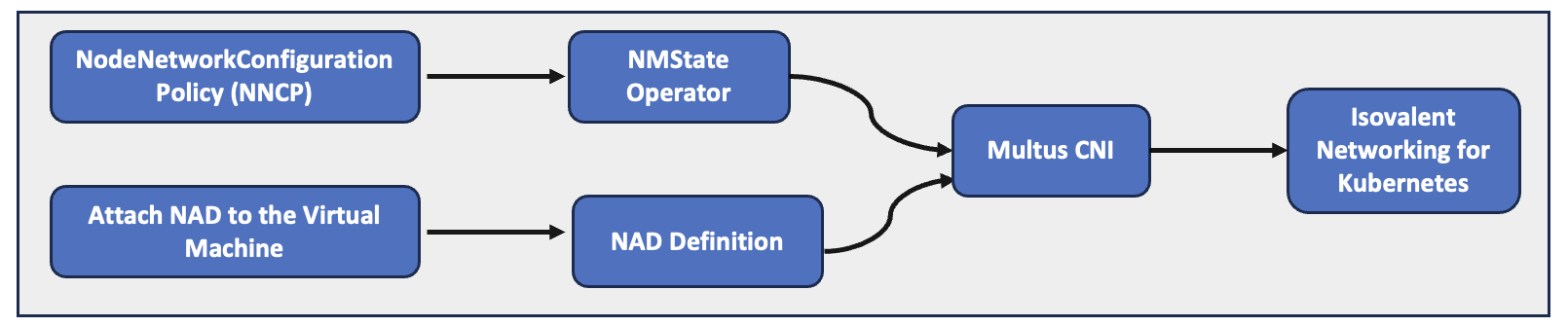
In OpenShift, the NMState Operator automates the deployment and management of NMState, allowing administrators to declaratively configure host-level networking through Kubernetes APIs without having to manually log into each node.
In this solution, NMState Operator CRD NodeNetworkConfigurationPolicy (NNCP) is used to configure the desired network settings like interfaces, bonds, bridges, IP assignments, routes and so on, using declarative yaml files. Any primary CNI plugin, such as Isovalent Cilium or OVN-Kubernetes, is responsible for providing and managing the pod’s primary (default) network interface (eth0), which is handled entirely by that plugin itself. In OpenShift, Multus is a CNI plugin that allows us to configure PODs or VMs with the multiple network interfaces. This feature is especially important in OpenShift virtualization as it is very common that a VM attached one or more networks.
In this solution, NMState Operator CRD NodeNetworkConfigurationPolicy (NNCP) is used to configure the desired network settings like interfaces, bonds, bridges, IP assignments, routes and so on, using declarative yaml files. Then, using Multus’ NetworkAttachmentDefinition CRD, additional secondary networks have been defined by specifying things like VLAN tag, bridge devices, MTU and so on. Once the NADs for secondary networks are in place, PODs or VMs can be attached to NADs to have secondary network interfaces.

Figure 17 illustrates networking is configured for OpenShift.
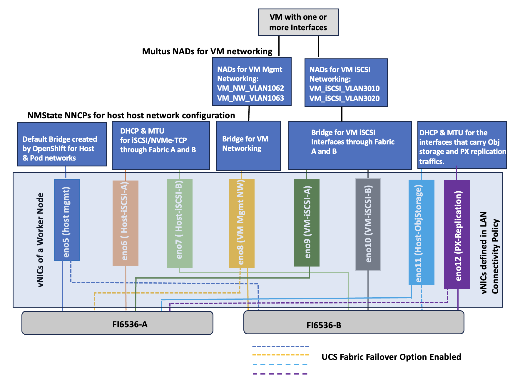
Figure 17 illustrates how networking is configured in OpenShift. Eno5 vNIC is used for host management as well as internal pod network. During the OpenShift installation, a default bridge (br-ex) is created, and it serves as default bridge for pod networking. Eno8 is used for VM front end connectivity for VMs hence a bridge (br-vm-mgmt) is created using NNCP. Multiple networks (for instance VM_NW_VLAN1062, VM_NW_VLAN1063 and so on) each with different vlans can be created using NADS. Eno11 is used for host object storage network (connected to FlashBlade) for PX-backup traffic. The NNCP sets the IP addresses and MTU to 9000 on this vNIC. Eno12 is used for data replication traffic by Portworx nodes running on the OpenShift cluster and configured with mtu 9000. These vNICs (eno6, eno8, eno11, and eno12) are configured with Cisco UCS Fabric Failover which will fail the vNIC over to the other FI in case of an FI failure or reboot.
Eno6 and eno7 interfaces are used for host storage access over iSCSI or NVMe-TCP protocols each vNIC pinning to the Fabric A and B respectively. NNCP sets the IP address by using DHCP, MTU to 9000 and creates additional interfaces of type VLAN for storage traffic using NVMe-TCP protocol.
Optionally, eno9 and eno10 interfaces are used for In-Guest direct access to the storage for the virtual machines using iSCSI protocol each vNIC pinning to Fabric-A and Fabric-B respectively. NNCP creates a linux bridges on each interface (iscsi-vm-a, iscsi-vm-b) and NADs will define two networks (VM_iSCSI_VLAN3010, VM_iSCSI_VLAN3020) for VMs storage access.
Note: It is required that these VLANs are configured in the Cisco Nexus switches and in the Cisco UCS Domain Profile VLAN policy and in the Ethernet Network Group policy attached to the vNIC in the LAN Connectivity policy.
Note: NADs configured in the default namespace or project are globally available to VMs in any namespace. NADs can also be configured in a specific namespace and are then only visible to VMs in that namespace.
VLAN and VSAN Configuration
Table 1 lists the VLAN and VSAN IDs configured for setting up the FlashStack environment.
Table 1. VLANs used in this solution
| VLAN ID |
Name |
Usage |
IP Subnet used in this Deployment |
| 2 |
Native-VLAN |
VLAN2 is used as native VLAN instead of default VLAN1 |
|
| 1060 |
OOB-Mgmt-VLAN |
Out-of-band management VLAN to connect management port for various devices |
10.106.0.0/24 GW: 10.106.0.254 |
| 1061 |
IB-Mgmt-VLAN |
Routable Bare Metal VLAN used for OpenShift cluster and node management |
10.106.1.0/24 GW: 10.106.1.254 |
| 1062 |
VM-Mgmt-VLAN1062 |
VM management network with VLAN 1062 |
10.106.2.0/24 GW: 10.106.2.254 |
| 1063 |
VM-Mgmt-VLAN1063 |
VM management network with VLAN 1063 |
10.106.3.0/24 GW: 10.106.3.254 |
| 3010 |
iSCSI-NVMe-TCP_A |
Used for OpenShift iSCSI/NVMe-TCP persistent storage using Fabric-A |
192.168.51.0/24 |
| 3020 |
iSCSI-NVMe-TCP_B |
Used for OpenShift iSCSI/NVMe-TCP persistent storage using Fabric-B |
192.168.52.0/24 |
| 3040 |
Object-storage |
Used for Object Storage traffic |
192.168.40.0/24 |
| 3050 |
Px-Replication |
Used for carrying replication traffic among the PX nodes |
192.168.50.0/24 |
| VSAN ID |
Name |
Usage |
| 103 |
VSAN-A |
For Fibre Channel storage traffic through MDS-A |
| 104 |
VSAN-B |
For Fibre Channel storage traffic through MDS-B |
Table 2 lists the infrastructure services running on either virtual machines or bar mental servers required for deployment as outlined in the document. All these services are hosted on pre-existing infrastructure with in the FlashStack.
Table 2. Infrastructure services
| Service Description |
VLAN |
IP Address |
| AD/DNS-1 & DHCP |
1061 |
10.106.1.21 |
| AD/DNS-2 |
1061 |
10.106.1.22 |
| OCP installer/bastion node |
1061 |
10.106.1.23 |
| Cisco Intersight Assist Virtual Appliance |
1061 |
10.106.1.24 |
Software Revisions
The FlashStack Solution with Red Hat OpenShift on Bare Metal infrastructure configuration is built using the following components.
Table 3 lists the required software revisions for various components of the solution.
| Layer |
Device |
Image Bundle Version |
| Compute |
A pair of Cisco UCS Fabric Interconnect – 6536 Cisco UCS X215 M8 with Cisco VIC 15230 Cisco UCSC-C245 M8 with Cisco VIC 15237 Cisco UCSC-C225 M8 with Cisco VIC 15237 |
6.0(1.250198) -6.0(1.250122) 6.0(1.250131) 6.0(1.250131) |
| Network |
Cisco Nexus 93699CD-GX-NX-OS Cisco MDS 9132T |
10.3(5)(M) 8.4(2c) |
| Storage |
Pure Storage FlashArray Purity //FA Pure Storage FlashBlade//S200 |
Purity//FA 6.9.0 Purity//FB 4.5.0 |
| Software |
Red Hat OpenShift |
4.18.26 |
| Isovalent Networking for Kubernetes Hubble-UI version |
1.17 1.3.5 |
|
| Portworx Enterprise Px-Backup |
3.4.0 2.9.0 |
|
| Cisco Intersight Assist Appliance |
1.1.1-0 |
|
| NVIDIA GPU L40S and H100 NVL Driver version |
580.95.05 |
Deployment Hardware and Software
This chapter contains the following:
● Cisco Nexus Switch Manual Configuration
● Claim Cisco Nexus Switches into Cisco Intersight
Physical cabling should be completed by following the diagram and table references in section FlashStack Cabling.
The following procedures describe how to configure the Cisco Nexus 93600CD-GX switches for use in a FlashStack environment. This procedure assumes the use of Cisco Nexus 9000 10.3(5), the Cisco suggested Nexus switch released at the time of this validation.
The procedure includes the setup of NTP distribution on both the mgmt0 port and the in-band management VLAN. The interface-vlan feature and ntp commands are used to set this up. This procedure also assumes that the default VRF is used to route the in-band management VLAN.
This document assumes that initial day-0 switch configuration is already done using switch console ports and ready to use the switches using their management IPs.
Cisco Nexus Switch Manual Configuration
Procedure 1. Enable features on Cisco Nexus A and Cisco Nexus B
Step 1. Log into both Nexus switches as admin using ssh.
Step 2. Enable the switch features as described below:
config t
feature nxapi
cfs eth distribute
feature udld
feature interface-vlan
feature netflow
feature hsrp
feature lacp
feature vpc
feature lldp
Procedure 2. Set Global Configurations on Cisco Nexus A and Cisco Nexus B
Step 1. Log into both Nexus switches as admin using ssh.
Step 2. Run the following commands to set the global configurations:
spanning-tree port type edge bpduguard default
spanning-tree port type edge bpdufilter default
spanning-tree port type network default
system default switchport
system default switchport shutdown
port-channel load-balance src-dst l4port
ntp server <Global-ntp-server-ip> use-vrf default
ntp master 3
clock timezone <timezone> <hour-offset> <minute-Offset>
clock summer-time <timezone> <start-weekk> <start-day> <start-month> <start-time> <end-week> <end-day> <enb-month> <end-time> <offset-minutes>
ip route 0.0.0.0/0 <IB-Mgmt-VLAN-gatewayIP>
copy run start
Note: It is important to configure the local time so that logging time alignment and any backup schedules are correct. For more information on configuring the timezone and daylight savings time or summer time, go to: https://www.cisco.com/c/en/us/td/docs/dcn/nx-os/nexus9000/102x/configuration/fundamentals/cisco-nexus-9000-nx-os-fundamentals-configuration-guide-102x/m-basic-device-management.html#task_1231769
Sample clock commands for the United States Eastern timezone are:
● clock timezone EST -5 0
● clock summer-time EDT 2 Sunday March 02:00 1 Sunday November 02:00 60
Procedure 3. Create VLANs on Cisco Nexus A and Cisco Nexus B
Step 1. From the global configuration mode, run the following:
Vlan <oob-mgmt-vlan-id> #1060
name OOB-Mgmt-VLAN
Vlan <ib-mgmt-vlan-id> #1061
name IB-Mgmt-VLAN
Vlan <native-vlan-id> #2
name Native-VLAN
Vlan <iscsi-NVMe-TCP_A-vlan-id> #3010
name iscsi-NVMe-TCP_A
Vlan <iscsi-NVMe-TCP_B-vlan-id> #3020
name iscsi-NVMe-TCP_B
Vlan <vm-mgmt1-vlan-id> #1062
name VM-Mgmt1
Vlan <vm-mgm2t-vlan-id> #1063
name VM-Mgmt2
Vlan < Object-storage> #3040
name Object-Storage
Vlan < PX_Replication> #3050
name PX_Replication
Procedure 4. Add NTP Distribution Interface
Cisco Nexus - A
Step 1. From the global configuration mode, run the following commands:
interface vlan <ib-mgmt-vlan-id>
ip address <switch-a-ntp-ip>/<ib-mgmt-vlan-netmask-length>
no shut
exit
ntp peer <switch-b-ntp-ip> use-vrf default
Cisco Nexus - B
Step 1. From the global configuration mode, run the following commands:
interface vlan <ib-mgmt-vlan-id>
ip address <switch-b-ntp-ip>/<ib-mgmt-vlan-netmask-length>
no shut
exit
ntp peer <switch-a-ntp-ip> use-vrf default
Procedure 5. Define Port Channels on Cisco Nexus A and Cisco Nexus B
Cisco Nexus – A and B
Step 1. From the global configuration mode, run the following commands:
interface port-channel 10
description vPC Peer Link
switchport mode trunk
switchport trunk native vlan 2
switchport trunk allowed vlan 1060-1062,3010,3020,3040,3050
spanning-tree port type network
interface port-channel 20
switchport mode trunk
switchport trunk native vlan 2
switchport trunk allowed vlan 1060-1062,3010,3020,3040,3050
spanning-tree port type edge trunk
mtu 9216
interface port-channel 30
switchport mode trunk
switchport trunk native vlan 2
switchport trunk allowed vlan 1060-1062,3010,3020,3040,3050
spanning-tree port type edge trunk
mtu 9216
interface port-channel 100
description vPC to AC10-Pure-FB-S200
switchport mode trunk
switchport trunk allowed vlan 3040
spanning-tree port type edge trunk
mtu 9216
### Optional: The below port channels is for connecting the Nexus switches to the existing customer network
interface port-channel 106
description connecting-to-customer-Core-Switches
switchport mode trunk
switchport trunk native vlan 2
switchport trunk allowed vlan 1060-1062
spanning-tree port type normal
mtu 9216
Procedure 6. Configure Virtual Port Channel Domain on Nexus A and Cisco Nexus B
Cisco Nexus - A
Step 1. From the global configuration mode, run the following commands:
vpc domain <nexus-vpc-domain-id>
peer-switch
role priority 10
peer-keepalive destination 10.106.0.6 source 10.106.0.5
delay restore 150
peer-gateway
auto-recovery
ip arp synchronize
Cisco Nexus - B
Step 1. From the global configuration mode, run the following commands:
vpc domain <nexus-vpc-domain-id>
peer-switch
role priority 20
peer-keepalive destination 10.106.0.5 source 10.106.0.6
delay restore 150
peer-gateway
auto-recovery
ip arp synchronize
Procedure 7. Configure individual Interfaces
Cisco Nexus-A
Step 1. From the global configuration mode, run the following commands:
interface Ethernet1/1
description FI6536-A-uplink-Eth1
channel-group 20 mode active
no shutdown
interface Ethernet1/2
description FI6536-B-uplink-Eth1
channel-group 30 mode active
no shutdown
interface Ethernet1/33
description Nexus-B-33
channel-group 10 mode active
no shutdown
interface Ethernet1/34
description Nexus-B-34
channel-group 10 mode active
no shutdown
## Optional: Configuration for interfaces that connected to the customer existing management network
interface Ethernet1/35/1
description customer-Core-1:Eth1/37
channel-group 106 mode active
no shutdown
interface Ethernet1/35/2
description customer-Core-2:Eth1/37
channel-group 106 mode active
no shutdown
Cisco Nexus-B
Step 1. From the global configuration mode, run the following commands:
interface Ethernet1/1
description FI6536-A-uplink-Eth2
channel-group 20 mode active
no shutdown
interface Ethernet1/2
description FI6536-B-uplink-Eth2
channel-group 30 mode active
no shutdown
interface Ethernet1/33
description Nexus-A-33
channel-group 10 mode active
no shutdown
interface Ethernet1/34
description Nexus-A-34
channel-group 10 mode active
no shutdown
## Optional: Configuration for interfaces that connected to the customer existing management network
interface Ethernet1/35/1
description customer-Core-1:Eth1/38
channel-group 106 mode active
no shutdown
interface Ethernet1/35/2
description customer-Core-2:Eth1/38
channel-group 106 mode active
no shutdown
Procedure 8. Update the port channels
Cisco Nexus-A and B
Step 1. From the global configuration mode, run the following commands:
interface port-channel 10
vpc peer-link
interface port-channel 20
vpc 20
interface port-channel 30
vpc 30
interface port-channel 100
vpc 100
interface port-channel 106
vpc 106
copy run start
Step 2. To check for correct switch configuration, run the following commands:
Show run
show vpc
show port-channel summary
show ntp peer-status
show cdp neighbors
show lldp neighbors
show udld neighbors
show run int
show int
show int status
Cisco Nexus Configuration for Storage Traffic
Procedure 1. Configure Interfaces for Pure Storage on Cisco Nexus and Cisco Nexus B
Cisco Nexus - A
Step 1. From the global configuration mode, run the following commands:
### Configuration for FlashArray//XL170
interface Ethernet1/27
description PureXL170-ct0-eth19
switchport access vlan 3010
spanning-tree port type edge
mtu 9216
no shutdown
interface Ethernet1/28
description PureXL170-ct1-eth19
switchport access vlan 3010
spanning-tree port type edge
mtu 9216
no shutdown
copy run start
### Configuration for FlashBlade//S200
interface Ethernet1/10
description vPC to AC10-Pure-FB-S200
switchport mode trunk
switchport trunk allowed vlan 3040
spanning-tree port type edge
mtu 9216
channel-group 100 mode active
no shutdown
interface Ethernet1/11
description vPC to AC10-Pure-FB-S200
switchport mode trunk
switchport trunk allowed vlan 3040
spanning-tree port type edge
mtu 9216
channel-group 100 mode active
no shutdown
Cisco Nexus - B
Step 1. From the global configuration mode, run the following commands:
### Configuration for FlashArray//XL170
interface Ethernet1/27
description PureXL170-ct0-eth18
switchport access vlan 3020
spanning-tree port type edge
mtu 9216
no shutdown
interface Ethernet1/28
description PureXL170-ct1-eth18
switchport access vlan 3020
spanning-tree port type edge
mtu 9216
no shutdown
copy run start
### Configuration for FlashBlade//S200
interface Ethernet1/10
description vPC to AC10-Pure-FB-S200
switchport mode trunk
switchport trunk allowed vlan 3040
spanning-tree port type edge
mtu 9216
channel-group 100 mode active
no shutdown
interface Ethernet1/11
description vPC to AC10-Pure-FB-S200
switchport mode trunk
switchport trunk allowed vlan 3040
spanning-tree port type edge
mtu 9216
channel-group 100 mode active
no shutdown
Claim Cisco Nexus Switches into Cisco Intersight
Cisco Nexus switches can be claimed into the Cisco Intersight either using Cisco Intersight Assist or Direct claim using Device ID and Claim Codes.
This section provides the steps to claim the Cisco Nexus switches using Cisco Intersight Assist.
Note: This procedure assumes that Cisco Intersight is already hosted outside the OpenShift cluster and claimed into the Intersight.com.
Procedure 1. Claim Cisco Nexus Switches into Cisco Intersight using Cisco Intersight Assist
Cisco Nexus - A
Step 1. Log into Nexus Switches and confirm the nxapi feature is enabled:
show nxapi
nxapi enabled
NXAPI timeout 10
HTTPS Listen on port 443
Certificate Information:
Issuer: issuer=C = US, ST = CA, L = San Jose, O = Cisco Systems Inc., OU = dcnxos, CN = nxos
Expires: Sep 12 06:08:58 2024 GMT
Step 2. Log into Cisco Intersight with your login credentials. From the drop-down list select System.
Step 3. Under Admin, click Target then click Claim a New Target. Under Categories, select Network, click Cisco Nexus Switch and then click Start.
Step 4. Select the Cisco Assist name which is already deployed and configured. Provide the Cisco Nexus Switch management IP address, username and password details and click Claim.
Step 5. Repeat steps 1 through 4 to claim the remaining Switch B.
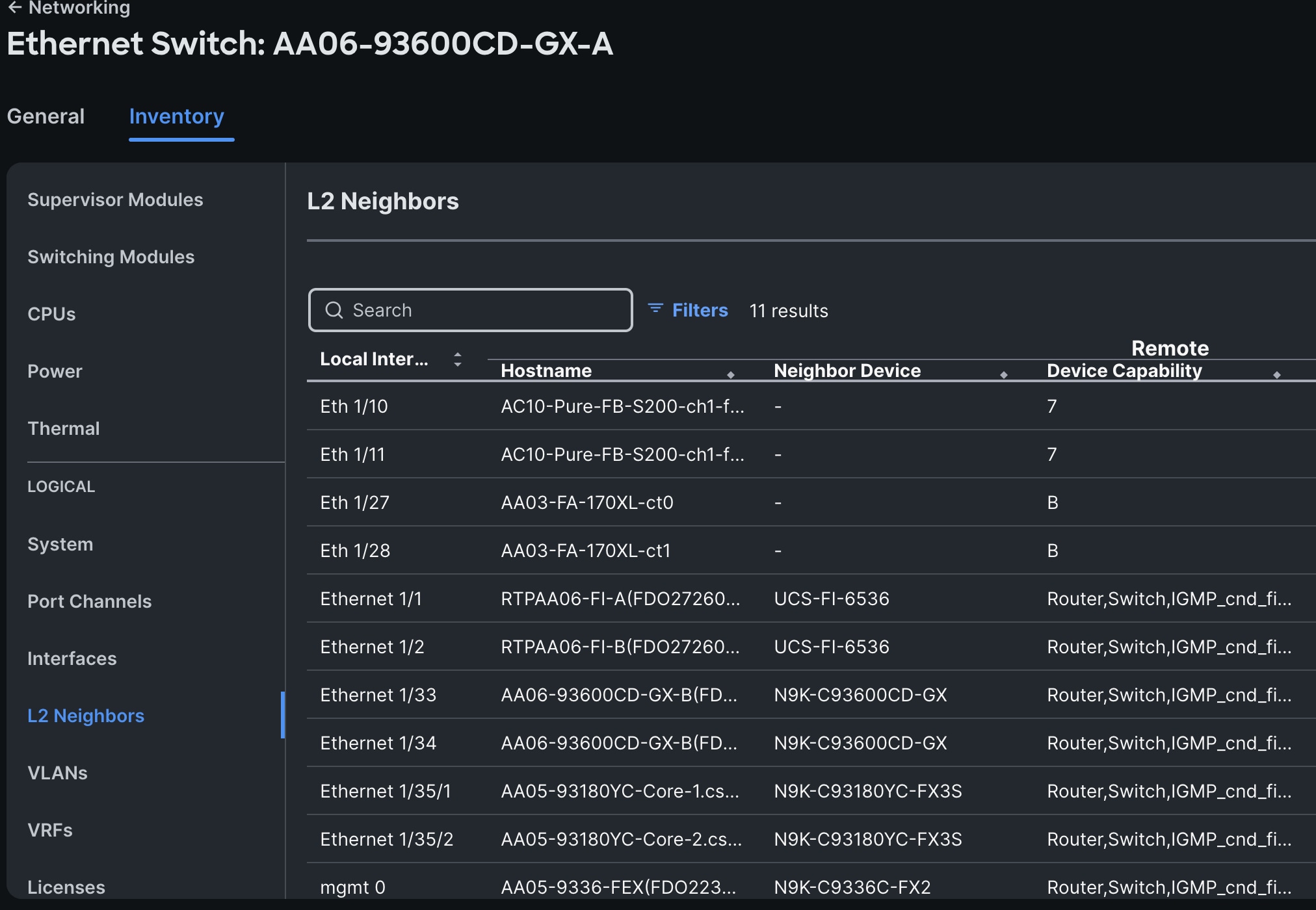
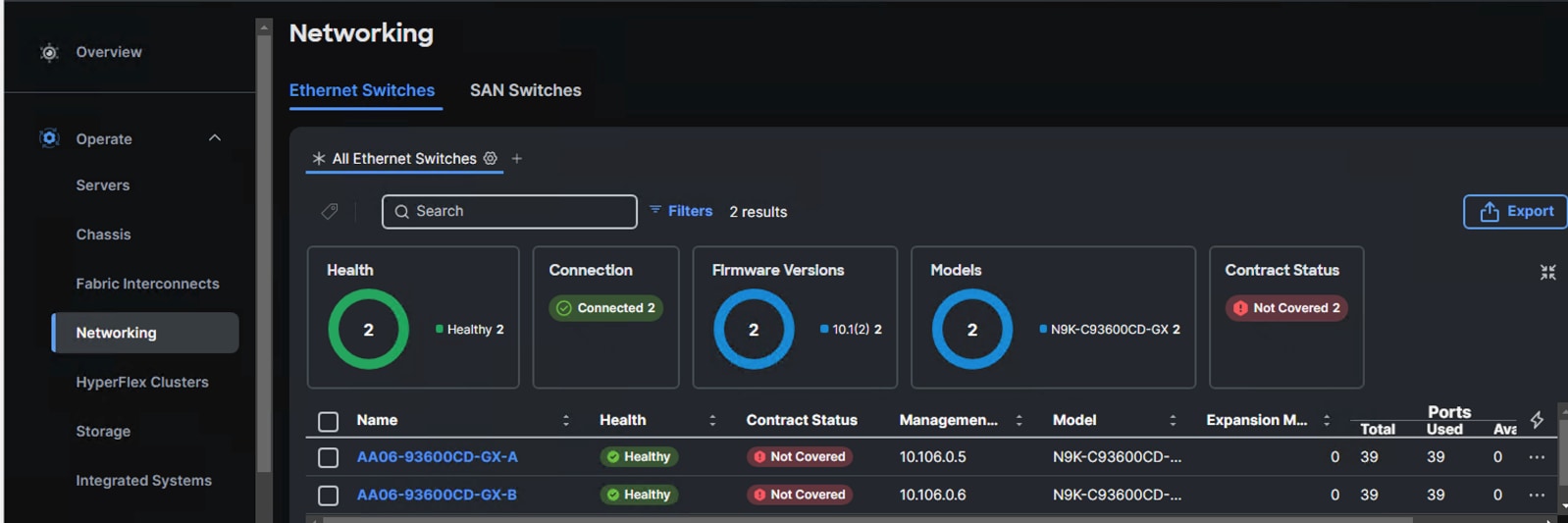
Step 6. When the switches are successfully claimed, from the drop-down list, select Infrastructure Services. Under Operate, click the Networking tab. On the right you will find the newly claimed Cisco Nexus switch details and browse through the Switches for viewing the inventory details.
The L2 neighbors of the Cisco Nexus Switch-A is shown below:
Pure Storage FlashArray Configuration
This chapter contains the following:
● iSCSI and NVMe-TCP Interfaces
● Fibre Channel Interfaces
In this solution, Pure Storage FlashArray//XL170 is used as the storage provider for all the application pods and virtual machines provisioned on the OpenShift cluster using Portworx Enterprise. The Pure Storage FlashArray//XL170 array will be used as Cloud Storage Provider for Portworx which allows us to store data on-premises with FlashArray while benefiting from Portworx Enterprise cloud drive features.
This chapter describes the high-level steps to configure Pure Storage FlashArray//X170 network interfaces required for storage connectivity over Ethernet and Fibre Channel.
Note: This document is not intended to explain every day-0 initial configuration steps to bring the array up and running. For detailed day-0 configuration steps, see: https://www.cisco.com/c/en/us/td/docs/unified_computing/ucs/UCS_CVDs/flashstack_ucs_xseries_e2e_5gen.html#FlashArrayConfiguration
As discussed in the previous steps, each storage controller of FlashArray is connected to the pair of Nexus switches using 2x 100GpE ports offering aggregated network bandwidth of 400Gbps from the two controllers. Similarly, each storage controller of FlashArray is connected to the pair of Cisco MDS switches using 4x 32Gbps ports offering aggregated fabric bandwidth of 256Gbps from the two controllers.
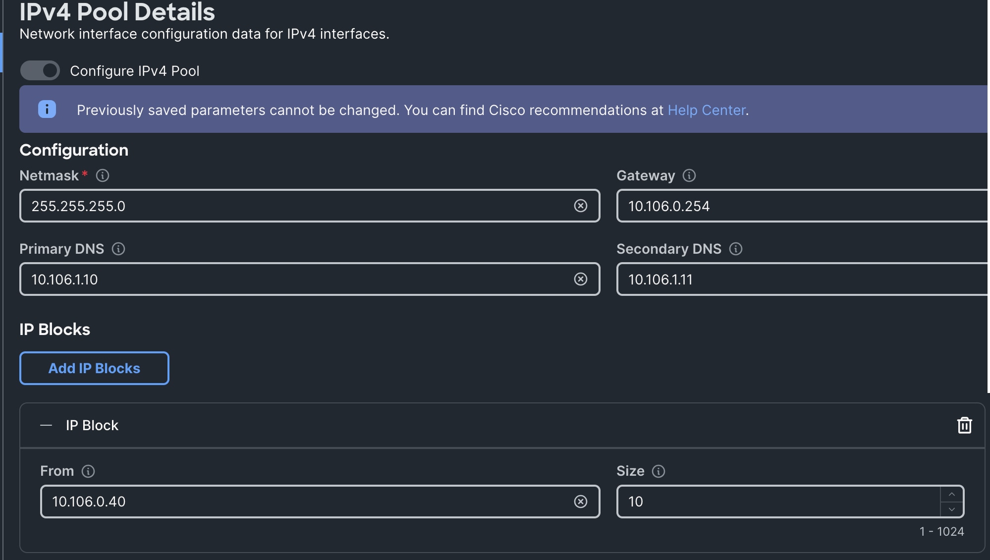
The Pure Storage FlashArray network settings were configured with three subnets across three VLANs. Storage Interfaces CT0.Eth0 and CT1.Eth0 were configured to access management for the storage on VLAN 1030. Storage Interfaces (CT0.Eth18, CT0.Eth19, CT1.Eth18, and CT1.Eth19) were configured to run iSCSI or NVMe-TCP Storage network traffic on the VLAN 3010 and VLAN 3020.
The following tables list the IP addressing configured on the interfaces used for storage access.
Table 4. Pure Storage FlashArray//XL170 Interface Configuration Settings
| FlashArray Controller |
iSCSI Port |
IP Address |
Subnet |
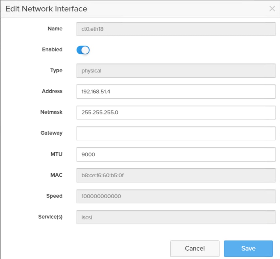
| FlashArray//X170 Controller 0 |
CT0.ETH18 |
192.168.51.4 |
255.255.255.0 |
| FlashArray//X170 Controller 1 |
CT1.ETH18 |
192.168.51.5 |
255.255.255.0 |
Table 5. Pure Storage FlashArray//XL170 Interface Configuration Settings
| FlashArray Controller |
iSCSI Port |
IP Address |
Subnet |
| FlashArray//X170 Controller 0 |
CT0.ETH19 |
192.168.52.4 |
255.255.255.0 |
| FlashArray//X170 Controller 1 |
CT1.ETH19 |
192.168.52.5 |
255.255.255.0 |
This section contains the procedures to configure the iSCSI interfaces.
Procedure 1. Configure iSCSI Interfaces
Step 1. Log into Pure FlashArray//XL170 using its management IP addresses.
Step 2. Click Settings > Network > Connectors > Ethernet.
Step 3. Click Edit for Interface CT0.eth18.
Step 4. Click Enable and add the IP information from Table 4 and Table 5 and set the MTU to 9000.
Step 5. Click Save.
Step 6. Repeat steps 1 through 5 to configure the remaining interfaces CT0.eth19, CT1.eth18 and CT1.eth19.
Step 7. If the Ethernet ports of FlashArray controllers are not configured with iSCSI service, then run the following command to enable iSCSI service on the Ethernet ports:
purenetwork eth setattr --servicelist iscsi ct1.eth18 ct1.18 ct0.eth19 ct1.eth19
Procedure 2. Configure Storage Interfaces for NVMe-TCP
The following steps are required only when you want to use nvme-tcp (instead of iscsi) protocol for accessing storage target.
Note: For this CVD, the ethernet ports that are used for iSCSI, are also used for NVMe-TCP validation.
Step 1. ssh to the Pure FlashArray//Xl170 using its management ip and pureuser credentials.
Step 2. Enable nvme-tcp service on all the four ethernet interfaces as shown below:
purenetwork eth setattr --servicelist nvme-tcp ct1.eth18 ct1.18 ct0.eth19 ct1.eth19
Note: For this validation, from the host side, the same network interfaces (eno6 and eno7) and the same VLANs (3010 and 3020) are also used for nvme-tcp.
Procedure 3. Fibre Channel Port Configuration
The WWNs of each fibre channel port on the storage controllers are preconfigured. It is required to gather WWNs of each fibre channel port which will be later used for creating Intersight boot policy and creation of Zones and Device aliases in MDS switches.
Table 6 lists the WWNs of fibre channel ports of each controller gathered from the FlashArray controllers.
Table 6. WWNs of Fibre Channel Ports
| FlashArray Controller |
FC Port |
WWN ID |
Service Enabled |
| FlashArray//X170 Controller 0 |
CT0.FC4 |
52:4A:93:7D:FE:FB:53:04 |
scsi-fc |
| FlashArray//X170 Controller 0 |
CT0.FC5 |
52:4A:93:7D:FE:FB:53:05 |
scsi-fc |
| FlashArray//X170 Controller 0 |
CT0.FC6 |
52:4A:93:7D:FE:FB:53:06 |
nvme-fc (not used in this validation) |
| FlashArray//X170 Controller 0 |
CT0.FC7 |
52:4A:93:7D:FE:FB:53:07 |
nvme-fc (not used in this validation) |
| FlashArray//X170 Controller 1 |
CT1.FC4 |
52:4A:93:7D:FE:FB:53:14 |
scsi-fc |
| FlashArray//X170 Controller 1 |
CT1.FC5 |
52:4A:93:7D:FE:FB:53:15 |
scsi-fc |
| FlashArray//X170 Controller 1 |
CT1.FC6 |
52:4A:93:7D:FE:FB:53:16 |
nvme-fc (not used in this validation) |
| FlashArray//X170 Controller 1 |
CT1.FC7 |
52:4A:93:7D:FE:FB:53:17 |
nvme-fc (not used in this validation) |
Note: As shown in Table 6, only two fibre channel ports, configured with scsi-fc service, are used for this CVD validation. The rest of the FC ports are, configured with nvme-fc serivice, are not used. For additional bandwidth, nvme-fc ports can be converted to scsi-fc.
Procedure 4. Claim Pure Storage FlashArray//XL170 into Intersight
Note: This procedure assumes that Cisco Intersight is already hosted outside the OpenShift cluster and Pure Storage FlashArray//XL170 is claimed into Intersight.com.
Step 1. Log into Cisco Intersight using your login credentials. From the drop-down menu select System.
Step 2. Under Admin, select Target and click Claim a New Target. Under Categories, select Storage, click Pure Storage FlashArray and then click Start.
Step 3. Select the Cisco Assist name which is already deployed and configured. Provide the Pure Storage FlashArray management IP address, username, and password details and click Claim.
Step 4. When the storage is successfully claimed, from the drop-down list, select Infrastructure Services. Under Operate, click Storage. You will see the newly claimed Pure Storage FlashArray; browse through it to view the inventory details.

Cisco Intersight Managed Mode Configuration for Cisco UCS
The chapter contains the following:
● Fabric Interconnect Domain Profile and Policies
● Server Profile Templates and Policies
● vNIC Templates, vNICs and LAN Connectivity Policy
● Ethernet Adapter Policy for Storage Traffic
● vHBA Templates, vHBAs and SAN Connectivity Policy
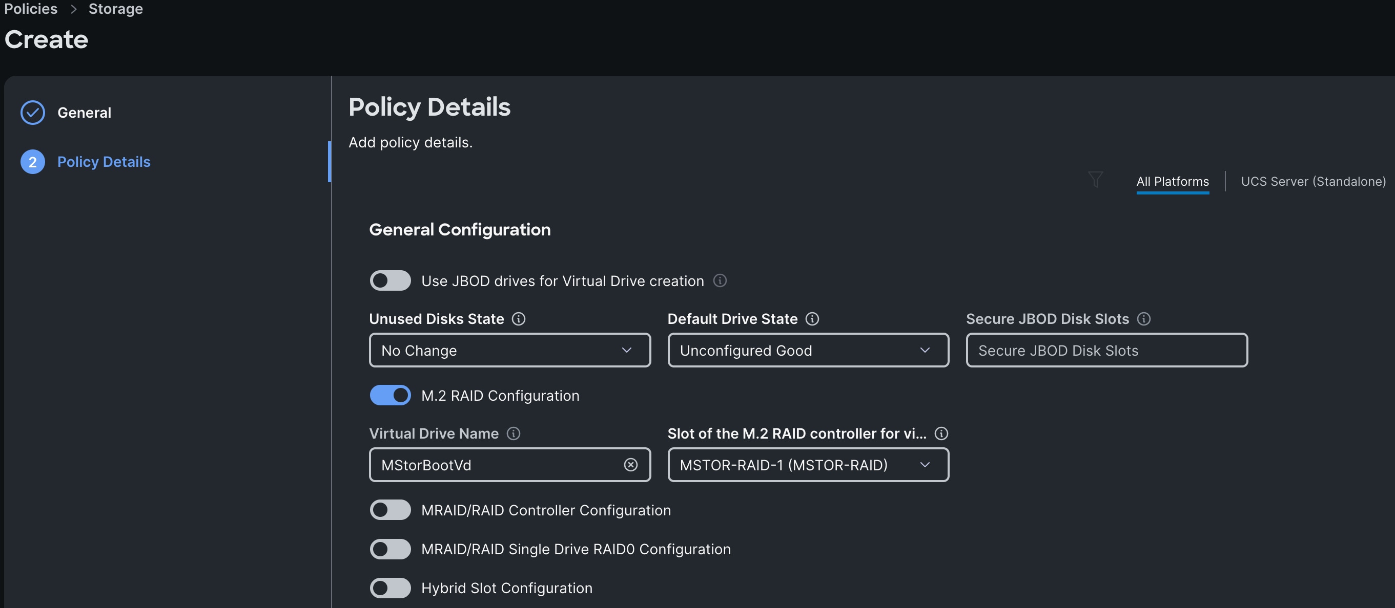
● Storage Policy for Local M.2 Boot
● Compute Configuration Policies
● Management Configuration Policies
● Cisco MDS 9132T Switch Manual Configuration
● Create Boot Volumes for SAN Boot
The procedures in this chapter describe how to configure a Cisco UCS domain for use in a base FlashStack environment. A Cisco UCS domain is defined as a pair for Cisco UCS FIs and all the X-Series and C-Series servers connected to it. These can be managed using two methods: UCSM and IMM. The procedures detailed below are for Cisco UCS Fabric Interconnects running in Intersight managed mode (IMM).
The Cisco Intersight platform is a management solution delivered as a service with embedded analytics for Cisco and third-party IT infrastructures. The Cisco Intersight Managed Mode (also referred to as Cisco IMM or Intersight Managed Mode) is an architecture that manages Cisco Unified Computing System (Cisco UCS) fabric interconnect–attached systems through a Redfish-based standard model. Cisco Intersight managed mode standardizes both policy and operation management for Cisco UCS C-Series M8 and Cisco UCS X-Series M8 compute nodes used in this deployment guide.
Note: This deployment guide assumes an Intersight account is already created, configured with required licenses and ready to use. Intersight Default Resource Group and Default Organizations are used for claiming all the physical components of the FlashStack solution.
Note: This deployment guide assumes that the initial day-0 configuration of Fabric Interconnects is already done in the IMM mode and claimed into the Intersight account.
Fabric Interconnect Domain Profile and Policies
This section contains the procedures to create fabric interconnect domain profiles and policies.
Procedure 1. Create Fabric Interconnect Domain Profile and Policies
Step 1. Log into the Intersight portal and select Infrastructure Service. On the left select Profiles then select UCS Domain Profiles.
Step 2. Click Create UCS Domain Profile to create a new domain profile for Fabric Interconnects. Under the General tab, select the Default Organization, enter a name and descriptions of the profile.
Step 3. Click Next to go to UCS Domain Assignment. Click Assign Later.
Step 4. Click Next to go to VLAN & VSAN Configuration.
Step 5. Under VLAN & VSAN Configuration > VLAN Configuration, click Select Policy then click Create New.
Step 6. On the Create VLAN page, go to the General tab, enter a name (AA06-FI-VLANs) and click Next to go to Policy Details.
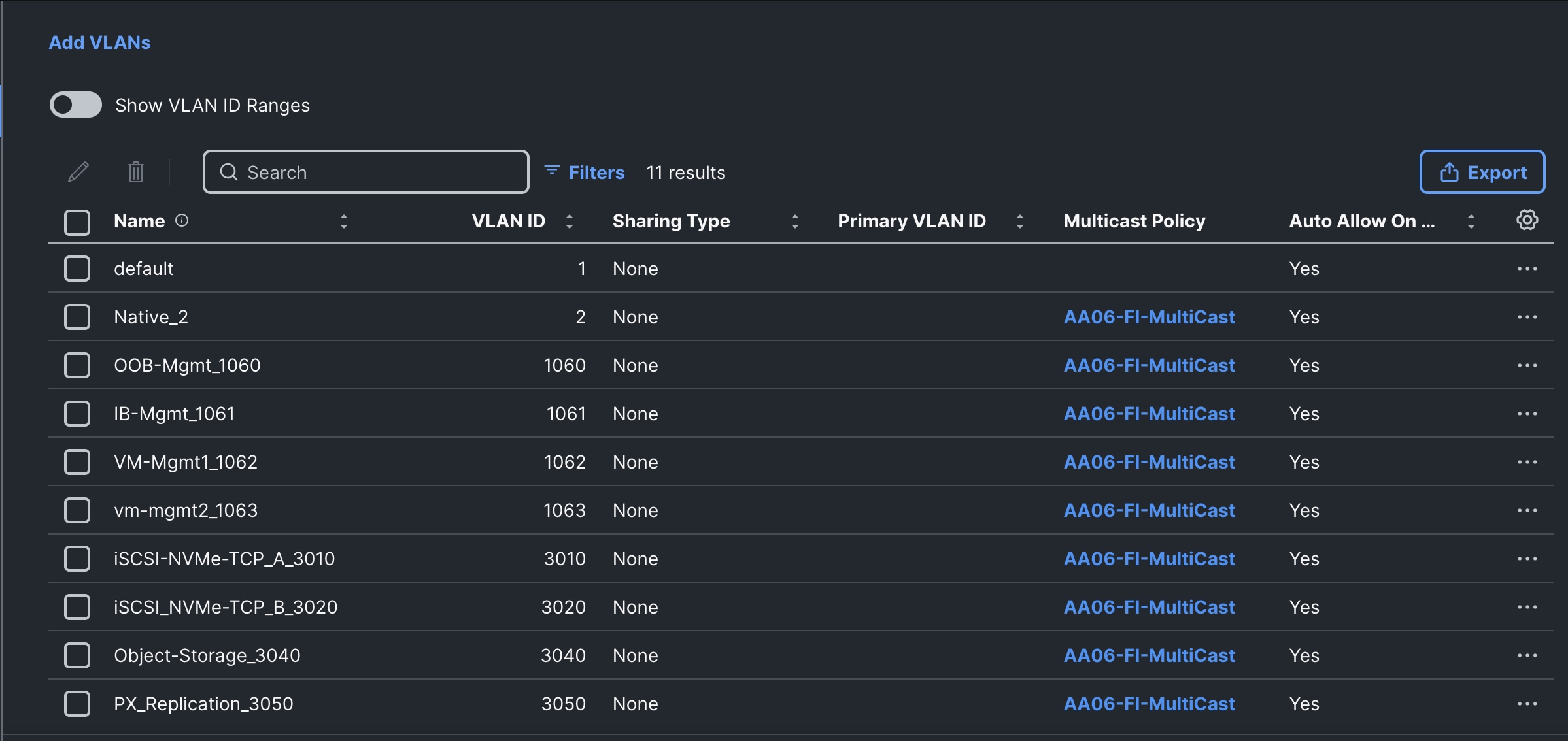
Step 7. To add a VLAN, click Add VLANs.
Step 8. For the Prefix, enter the VLAN name as OOB-Mgmt-VLAN. For the VLAN ID, enter the VLAN ID 1061. Leave Auto Allow on Uplinks enabled and Enable VLAN Sharing disabled.
Step 9. Under Multicast Policy, click Select Policy and select Create New to create a Multicast policy.
Step 10. On the Create Multicast Policy page, enter the name (AA06-FI-MultiCast) of the policy and click Next to go to Policy Details. Leave the Snooping State and Source IP Proxy state checked/enabled and click Create. Select the newly created Multicast policy.
Step 11. Repeat steps 1 through 10 to add all the required VLANs to the VLAN policy.
Step 12. After adding all the VLANs, click Set Native VLAN ID and enter the native VLANs (for example 2) and click Create. The VLANs used for this solution are shown below:
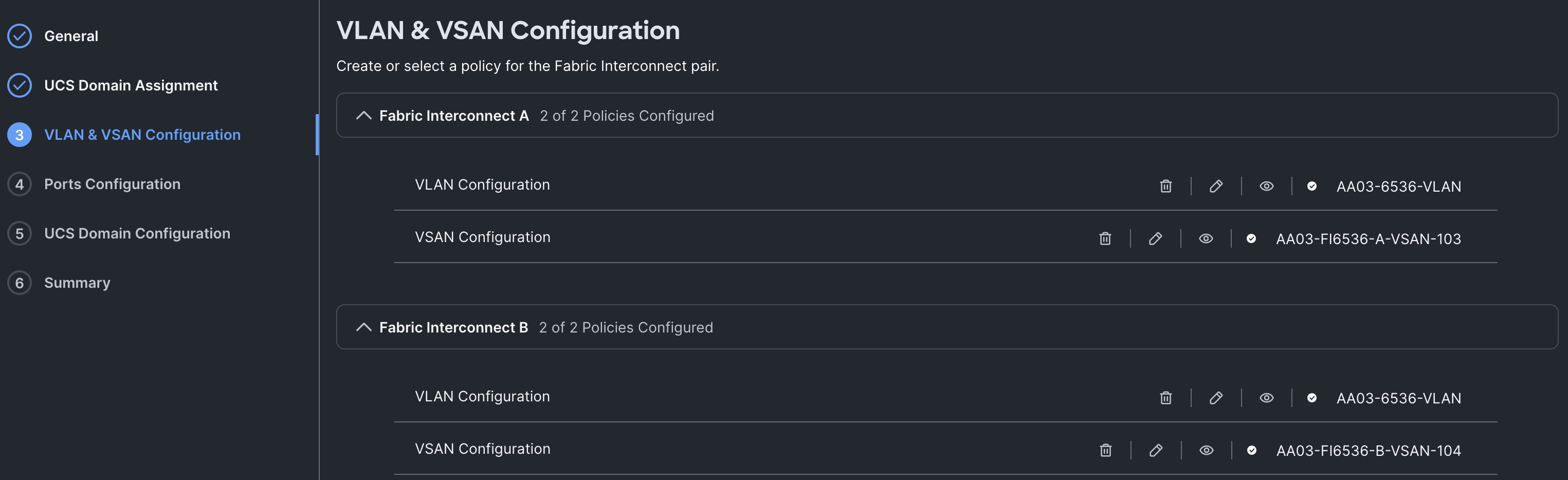
Step 13. Select the newly created VLAN policy for both Fabric Interconnects A and B.
Step 14. Click Select Policy to create a VSAN policy for Fabric-A. Provide a name to the VSAN policy (AA03-FI6536-A-VSAN-103). Click Next.
Step 15. Enable the Uplink Trunking option. Click Add VSAN. Provide name (MDSUplink103), select Uplink for VSAN Scope, set VSAN and FCoE VLAN IDs to 103. Click Save. Click Create to complete the creation of the VSAN policy for Fabric-A.
Step 16. Repeat steps 14 and 15 to create another VSAN policy (AA03-FI6536-B-VSAN-104) for Fabric-B with VSAN and FCoE IDs as 104. The final VLAN and VSAN configurations is shown below:
Step 17. Click Next to go to Ports Configuration. Create a new Ports Configuration Policy for Fabric Interconnect -A (AA03-FI-A-PortConfig).
Step 18. Enter the name of the policy (AA03-FI-PortConfig) and click Next.
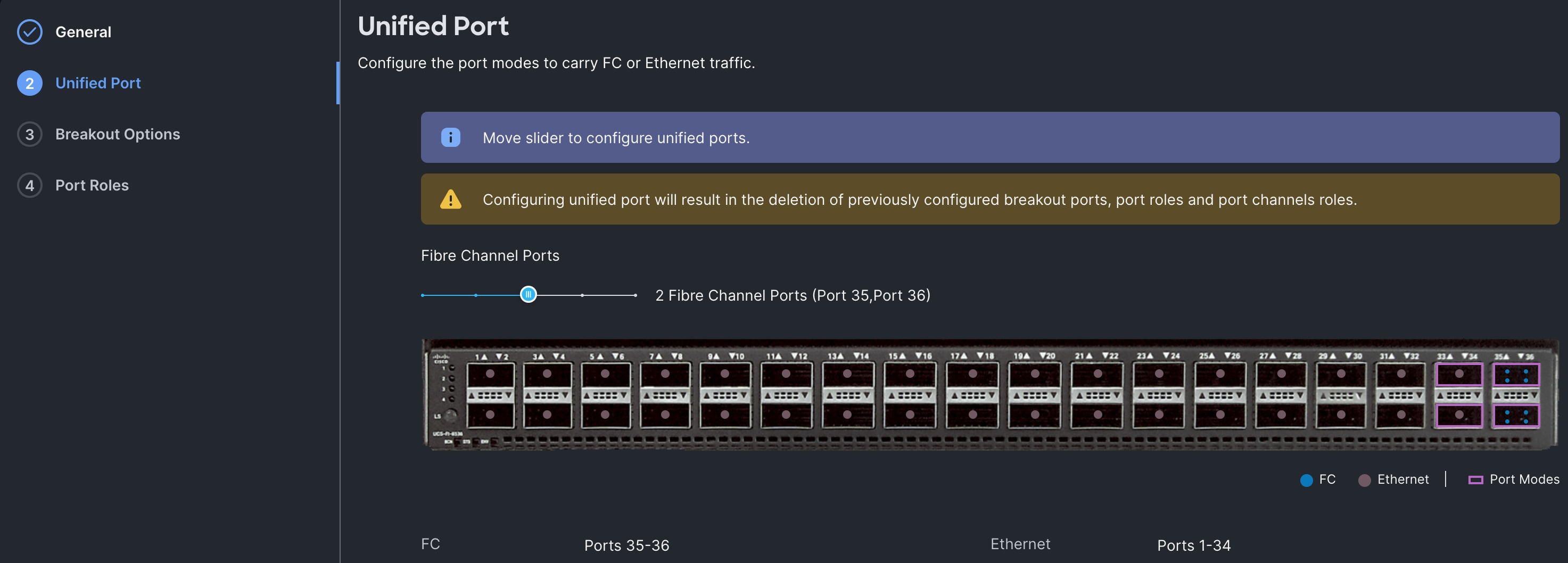
Step 19. For the Unified Port option, ensure the last two ports (35 and 36) are configured as unified ports by adjusting the slide. Click Next.
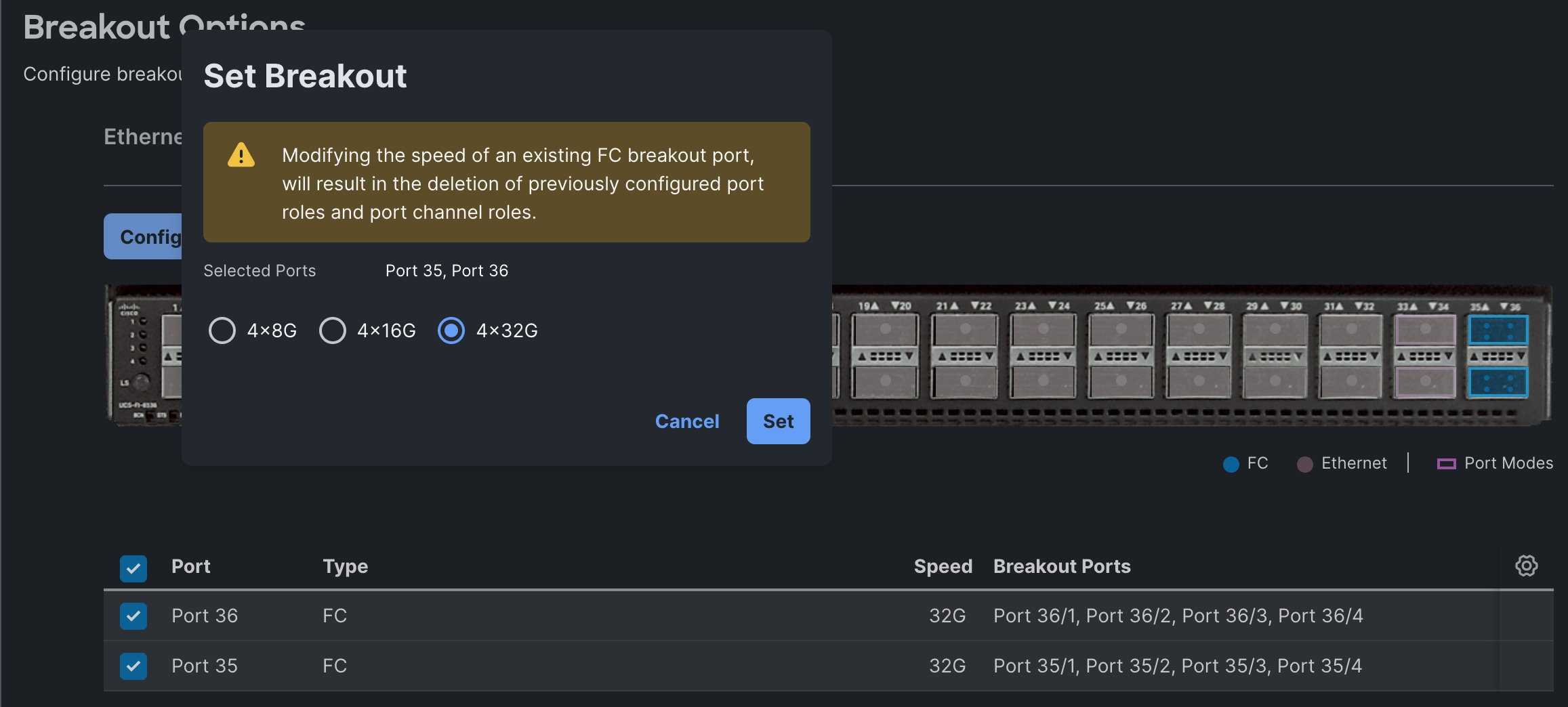
Step 20. Under Breakout option, click the Fibre Channel tab, select ports 35 and 36 and click Configure. Select option 4x32G and click Set. Click Next to go the Port Roles page.
Step 21. For defining server ports, click Port Roles, select ports from 3 to 11 and click Configure. For Role, select Server for and click Save.
Step 22. Go to Port Channels > Create Port Channel . First select ports 1 and 2, then set Role to Ethernet Uplink Port Channel. Enter 11 for the Port Channel ID. Set Admin speed to 100Gbps and FEC to Cl91. Under Link Control, create a new link control policy with settings from Table 7. Once created, select the policy.
Step 23. Click Create Port Channel to create a port channel for FC. Select ports 36/1, 36/2,36/3 and 36/4, then set Role to FC Uplink Port Channel, set Port channel ID to 203, ensure to set 32Gbps for Admin Speed, and VSAN ID to 103. Click Save.
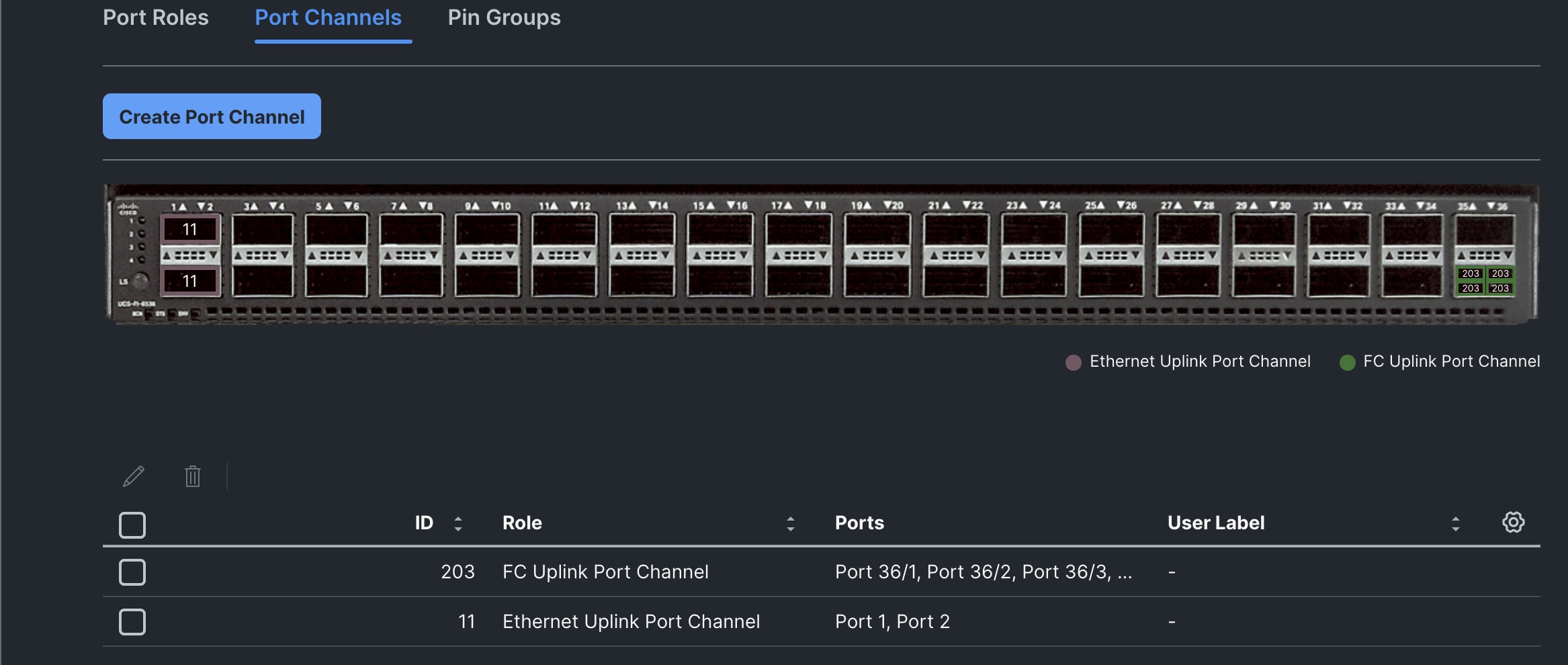
Step 24. Click Save to complete the port configuration for FI-A. Repeat steps 21, 22, and 23 to create Port rules ( AA03-FI-B-PortConfig) for FI-B. Set 12 for Ethernet Port Channel ID, 204 for FC Port Channel ID and 104 for VSAN ID.
Step 25. For Link Control policy of Ethernet Uplink configuration, create a new link control policy with the options in Table 7. Once created, select the policy.
| Policy Name |
Setting Name |
| AA06-FI-LinkControll |
UDLD Admin State: True UDLD mode: Normal |
Step 26. Once two Port configurations selected for FI-A and B, click Next to go to the UCS Domain Configuration page.
The following tables lists the Management and Network related policies that are created and used.
| Policy Name |
Setting Name |
| AA06-FI-OCP-NTP |
Enable ntp: on Server list: 172.20.10.11,172.20.10.12,172.20.10.13 Timezone: America/New_York |
Table 9. Network Connectivity Policy
| Policy Name |
Setting Name |
| AA06-FS-OCP-NWPolicy |
Proffered IPV4 DNS Server: 10.106.1.21 Alternate IPV4 DNS Server: 10.106.1.22 |
| Policy Name |
Setting Name |
| AA06-FS-OCP-SNMP |
Enable SNMP: On (select Both v2c and v3) Snmp Port: 161 System Contact: your snmp admin email address System location: Location details snmp user: Name: snmpadmin Security level: AuthPriv Set Auth and Privacy passwords. |
| Policy Name |
Setting Name |
| AA06-FS-OCP-SystemQoS |
Best Effort: Enable Weight: 5 MTU: 9216 |
Step 27. When the UCS Domain profile is created with the policies, edit the policy and assign it to the Fabric Interconnects.
Intersight will go through the discovery process and discover all the Cisco UCS C and X-Series compute nodes attached to the Fabric Interconnects.
Server Profile Templates and Policies
In the Cisco Intersight platform, a server profile enables resource management by simplifying policy alignment and server configuration. The server profiles are derived from a server profile template. A Server profile template and its associated policies can be created using the server profile template wizard. After creating the server profile template, you can derive multiple consistent server profiles from the template.
The server profile templates captured in this deployment guide supports Cisco UCS X210c M7 compute nodes with 5th Generation VICs and can be modified to support other Cisco UCS blades and rack mount servers.
The following pools need to be created before proceeding with server profile template creation.
MAC Pools
Table 12 lists the two MAC pools for the vNICs that will be configured in the templates.
Table 12. MAC Pool Names and Address Ranges
| MAC Pool Name |
Address Ranges |
| AA06-OCP-MACPool-A |
From: 00:25:B5:A6:0A:00 Size: 64 |
| AA06-OCP-MACPool-B |
From: 00:25:B5:A6:0B:00 Size: 64 |
UUID Pool
Table 13 lists the settings for the UUID pools.
Table 13. UUID Pool Names and Settings
| UUID Pool Name |
Settings |
| AA06-OCP-UUIDPool |
UUID Prefix: AA060000-0000-0001 From: AA06-000000000001 To: AA06-000000000080 Size: 128 |
Procedure 1. Create Out-Of-Band (OOB) Management IP Pool
Step 1. Create the OOB management IP pool (AA06-OCP-OOB-MGMT-IPPool) with the following settings:
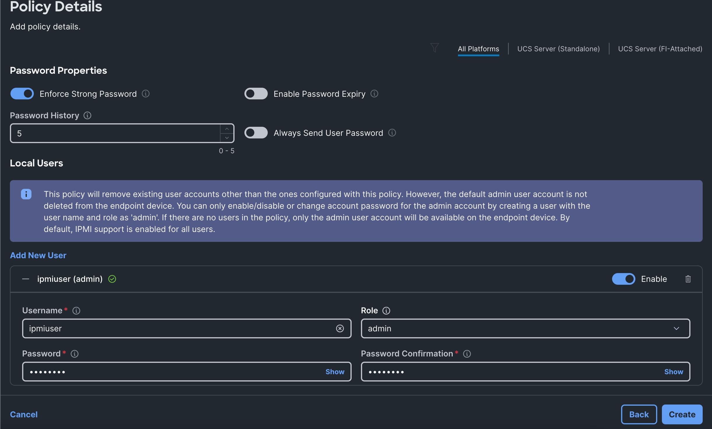
vNIC Templates, vNICs and LAN Connectivity Policy
For an IP-Based FlashStack design, in a mixed cluster validation, where control plane nodes are configured to run the workloads, control plane nodes also need to be configured with storage network interfaces. Hence single server profile template is created for both worker and control plane nodes.
The following vNIC templates are used for deriving the vNICs for OpenShift nodes for host management, VM management and storage traffics.
Table 14. vNIC Templates used for IP-Based FlashStack Design
| Template Name |
AA06-OCP-Mgmt-vNIC Template |
AA06-OCP-iSCSIA-vNIC Template |
AA06-OCP-iSCSIB-vNIC Template |
AA06-VMMgmt-vNIC Template |
ObjectStorage vNIC Template |
AA06 -PX-Replication vNIC Template |
| Purpose |
In-Band management of OpenShift hosts |
iSCSI traffic through fabric-A (OpenShift -host and VM’s In-Guest) |
iSCSI traffic through fabric-B (OpenShift -host and VM’s In-Guest) |
VM management networks |
Host access to the Object storage access (FlashBlade) |
Carries replication data traffic among the PX nodes |
| Derived vNICs Names |
eno5 |
eno6 (for Host iSCSI traffic) eno9 (for VM iSCSI traffic) |
eno7 (for Host iSCSI traffic) eno10 (for VM iSCSI traffic) |
eno8 |
eno11 |
eno12 |
| Mac Pool |
AA06-OCP-MACPool-A |
AA06-OCP-MACPool-A |
AA06-OCP-MACPool-B |
AA06-OCP-MACPool-B |
AA06-OCP-MACPool-A |
AA06-OCP-MACPool-B |
| Switch ID |
A |
A |
B |
B |
A |
B |
| CDN Source setting |
vNIC Name |
vNIC Name |
vNIC Name |
vNIC Name |
vNIC Name |
vNIC Name |
| Fabric Failover setting |
Yes |
No |
No |
Yes |
Yes |
Yes |
| Network Group Policy name and Allowed VLANs and Native VLAN |
AA06-OCP-BareMetal-NetGrp: Native and Allowed VLAN: 1061 |
AA06-OCP-iSCSI-A-NetGrp: Native and Allowed VLAN: 3010 |
AA06-OCP-iSCSIB-NetGrp: Native and Allowed VLAN: 3020 |
AA06-OCP-VMMgmt-NetGrp Allowed VLANs: 1062,1063 Native VLAN: 1062 |
AA06-OCP-ObjectStoreNWG Native and Allowed Vlans: 3040 |
AA06-OCP-PX_replciationNWG Native and Allowed Vlans: 3050 |
| Network Control Policy Name and CDP and LLDP settings |
AA06-OCP-CDPLLDP: CDP Enabled LLDP (Tx and Rx) Enable |
|
|
|
|
|
| QoS Policy name and Settings |
AA06-OCP-MTU1500-MgmtQoS: Best Effort MTU: 1500 Rate Limit (Mbps): 100000 |
AA06-OCP-iSCSI-QoS: Best-effort MTU:9000 Rate Limit (Mbps): 100000 |
AA06-OCP-iSCSI-QoS: Best-effort MTU:9000 Rate Limit (Mbps): 100000 |
AA06-OCP-MTU1500-MgmtQoS: Best Effort MTU: 1500 Rate Limit (Mbps): 100000 |
AA06-OCP-iSCSI-QoS: Best-effort MTU:9000 Rate Limit (Mbps): 100000 |
AA06-OCP-iSCSI-QoS: Best-effort MTU:9000 Rate Limit (Mbps): 100000 |
| Ethernet Adapter Policy Name and Settings |
AA06-OCP-EthAdapter-Linux-v2: Uses system defined Policy: Linux-V2 |
AA06-OCP-EthAdapter-16RXQs-5G (refer to the following section) |
AA06-OCP-EthAdapter-16RXQs-5G (refer to the following section) |
AA06-OCP-EthAdapter-Linux-v2: Uses system defined Policy: Linux-V2 |
AA06-OCP-EthAdapter-16RXQs-5G (refer below section) |
AA06-OCP-EthAdapter-16RXQs-5G (refer to the following section) |
Ethernet Adapter Policy for Storage Traffic
The ethernet adapter policy is used to set the interrupts, send and receive queues, and queue ring size. The values are set according to the best-practices guidance for the operating system in use. Cisco Intersight provides a default Linux Ethernet Adapter policy for typical Linux deployments.
Optionally, you can configure a tweaked ethernet adapter policy for additional hardware receive queues handled by multiple CPUs in scenarios where there is a lot of traffic and multiple flows. In this deployment, a modified ethernet adapter policy, AA06-EthAdapter-16RXQs-5G, is created and attached to storage vNICs eno6, eno7, eno9, eno10, eno11 and eno12. Other vNICs (eno5 and eno8) will use the default Linux-v2 Ethernet Adapter policy. Table 15 lists the settings that are changed from defaults in the Adapter policy used for the iSCSI traffic. The remaining settings are left at defaults
Table 15. Ethernet Adapter Policy used for Storage traffic
| Setting Name |
Value |
| Interrupt Settings |
Interrupts: 19, Interrupt Mode: MSX, Interrupt Timer: 125 |
| Receive |
Receive Queue Count: 16, Receive Ring Size: 16384 |
| Transmit |
Transmit Queue Count: 1, Transmit Ring Size: 16384 |
| Completion |
Completion Queue Count: 17, Completion Ring Size: 1 |
| Interrupt Settings |
Interrupts: 19, Interrupt Mode: MSX, Interrupt Timer: 125 |
Using the templates listed in Table 14, single LAN connectivity policy is created for both control plane and worker nodes.
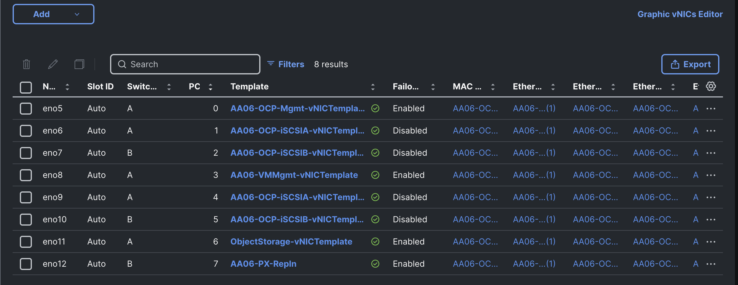
Note: With a dedicated control-plane nodes deployment, the LAN connectivity policy for control-plane nodes must be configured with a single vNIC for host management traffic. The rest of the vNICs are not required since they do not run workloads.
For FC-based FlashStack deployment, the vNICs (eno6,eno7,eno9,eno10 derived from AA06-OCP-iSCSIA and AA06-OCP-iSCSIB templates) that carry storage traffic over ethernet are not required to be configured. Hence, the LAN connectivity policy for FC-Based FlashStack design, would have only four vNICs (derived from templates: AA06-OCP-Mgmt, AA06-VMMgmt, ObjectStorage and AA06-PX-Repln) to carry management and other traffics. The below screenshot shows the LAN connectivity policy (AA06-OCP-Worker-LANConn_AMD_FCSAN) used for FC-based FlashStack deployment.
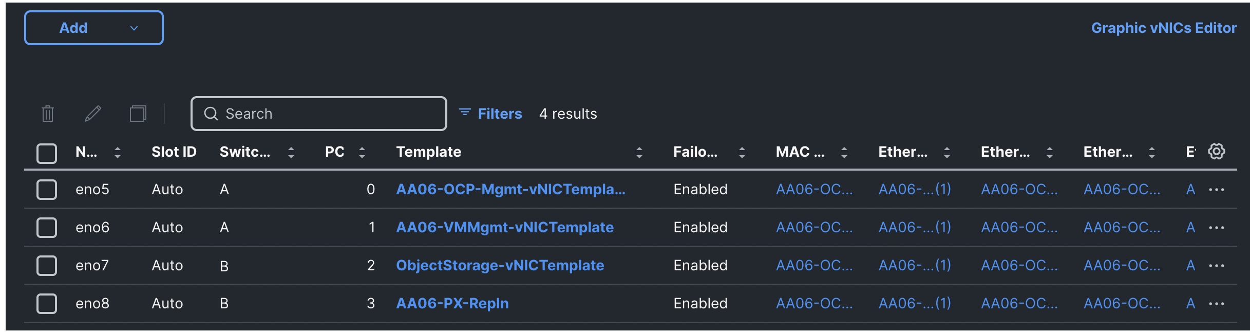
vHBA Templates, vHBAs and SAN Connectivity Policy
For FC-Based FlashStack design, Fibre Channel protocol is used for accessing the Storage through Cisco MDS Fibre Channel switches. Compute nodes are configured with required virtual HBAs (vHBAs) for accessing the FlashArray using Fibre Channel protocol. The Computes nodes are also configured to boot from FC SAN by leveraging vHBAs.
Table 16 provides vHBA templates used for deriving the required vHBAs for the FC-based FlashStack design.
Table 16. vHBA templates used for FC-Based FlashStack design
| Template Name |
AA06-OCP-vHBA-Temp-A |
AA06-OCP-vHBA-Temp-B |
| Purpose |
For FC Storage traffic through Fabric-A |
For FC Storage traffic through Fabric-B |
| Derived vHBA Names |
vHBA-A |
vHBA-B |
| HBA Type |
fc-Initiator |
fc-Initiator |
| WWPN Pool |
AA06-OCP-WWPN-Pool-A |
AA06-OCP-WWPN-Pool-B From: : 20:00:00:25:B5:00:0B:00 |
| Switch ID |
A |
B |
| FC Network |
Policy Name: AA06-OCP-VSAN103 |
Name: AA06-OCP-VSAN104 |
| FC QoS |
Policy Name: AA06-OCP-FC-QoS Rate Limit: 0 Priority: FC, Burts: 10240 |
|
| Fibre Channel Adapter |
Policy Name: AA06-OCP-FC-Adapter (with Default settings) |
|
Note: Required WWPN and WWNN pols need to be created before creating vHBA templates and SAN policy.
Using these vHBA templates, the following vHBAs are derived by creating the SAN Connectivity Policy (AA06-OCP-SANConn_AMD).
Note: Adjust the PCI order for vHBAs based on the number of vNICs derived in the LAN Connectivity policy.
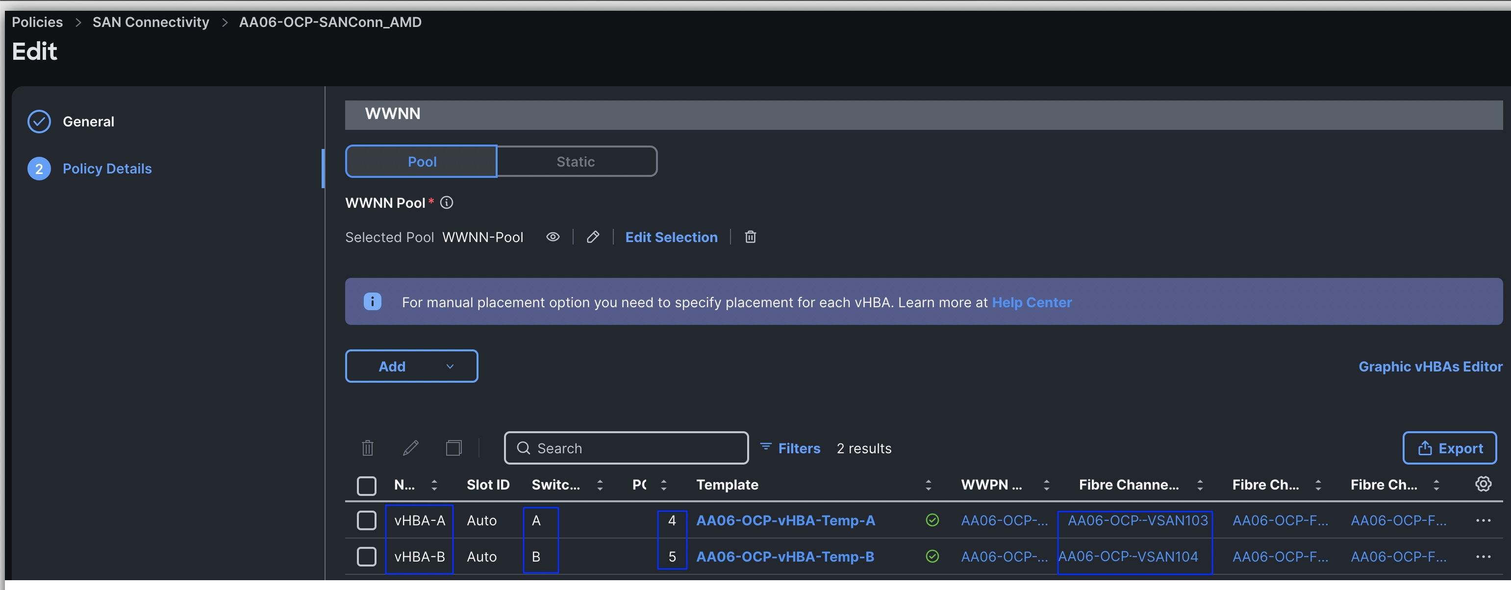
Storage Policy for Local M.2 Boot
For IP-Based FlashStack solution, Cisco UCS AMD M8 (X and C-Series) nodes are configured to boot from local M.2 SSD disks. Two M.2 disks are used and configured with RAID-1 configuration. Boot from SAN option will be supported in upcoming releases. The following screenshot shows the storage policy, and the settings used for configuring the M.2 disks in RAID-1 configuration.
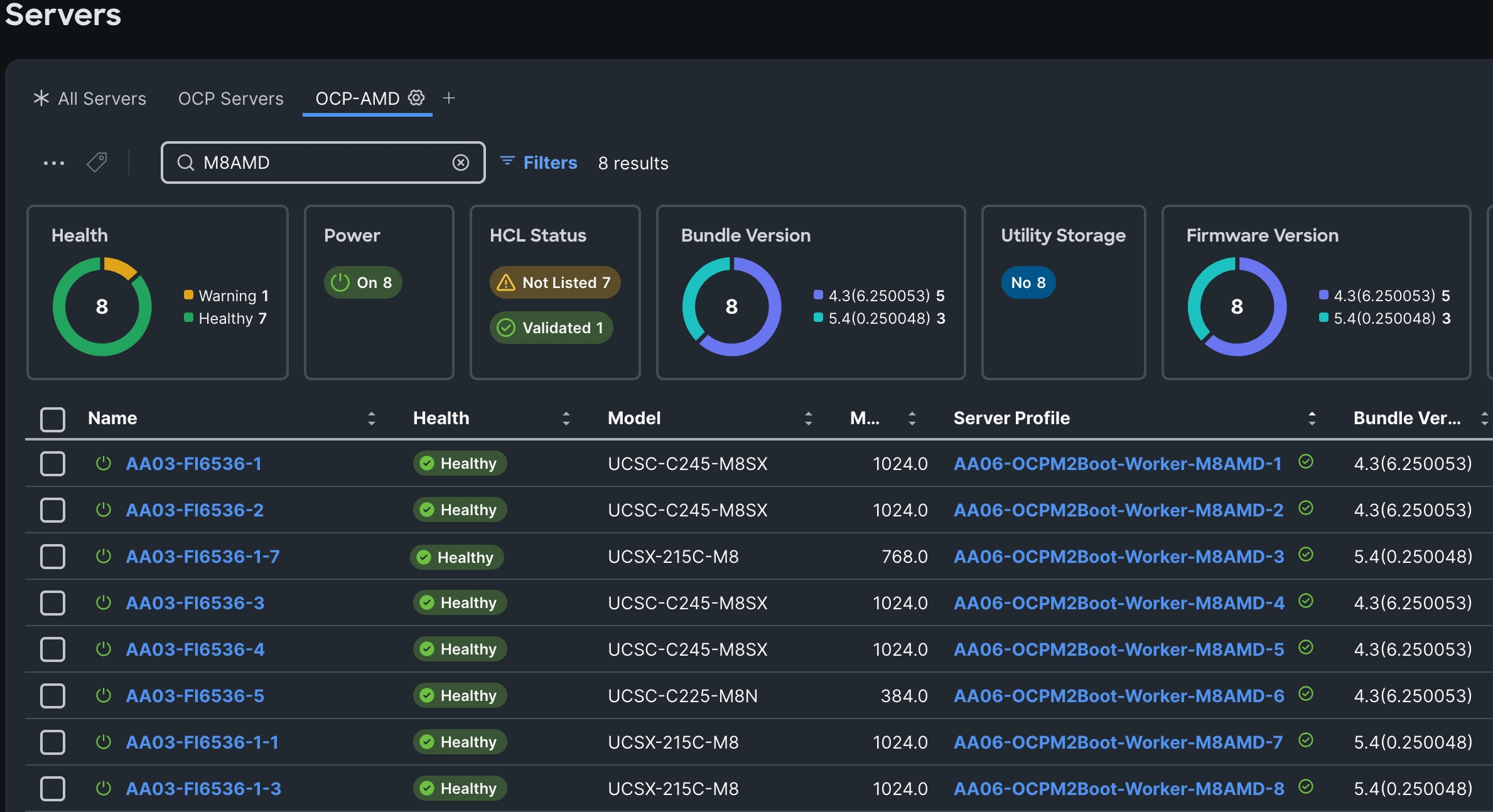
Note: In the absence of M.2 disks/controller in the servers, optionally, front loaded NVMe or SSD drives can be used in RAID1 configuration for OS installation. UCS-RAID Tri-mode raid controllers can be used for configuring these drives in Raid-1 configuration.
Note: In case of FC-based FlashStack deployment, the compute nodes are configured to boot from SAN. In that case, the above storage policy is not required. We would need to update the Boot policy with FlashArray Target WWNs. See the Boot Order policy for FC SAN Boot for more details.
Compute Configuration Policies
Boot Order Policy for M.2 Local boot
The following boot policy is used for both controller and worker nodes for IP-Based FlashStack design.
Note: Do not enable UEFI Secure Boot. Secure Boot needs to be disabled for the proper functionality of Portworx Enterprise and the NVIDIA GPU Operator GPU driver initialization.
The Local Disk boot option being at the top ensures that the nodes always boot from the M.2 disks once after CoreOS installed. The CIMC Mapped DVC option at the second is used to install the CoreOS using Discovery ISO which is mapped using a Virtual Media policy (CIMCMap-ISO). KVM Mapped DVD will be used if you want to manually mount any ISO to the KVM session of the server and install the OS. This option will be used when installing CoreOS during the OpenShift cluster expansion by adding additional worker node.
Note: Intersight integration with OpenShift Assisted installation console enables you to select the list of nodes that you want to use for OpenShift installation and boot them from the Discovery ISO without having you to download the Discovery ISO and boot the nodes manually with the Discovery ISO. This integration automatically creates a Intersight workflow “Boot servers from ISO URL” which downloads the Discovery ISO from Red Hat website, mount it to the servers, and boot each server with ISO. This enhancement saves lots of effort and time and improves deployment experience.

Boot Order Policy For FC SAN Boot
For FC-Based FlashStack design, compute nodes are configured to boot from SAN volumes. A separate boot order policy is created as detailed below. Refer the Table 6 for WWN ID of the FlashArray controllers and use the details in this policy. The Policy ensure that vHBA-A will establish connection with CT0.FC4 and CT1.FC4 ports while vHBA-B will connect to CT0.FC5 and CT1.FC5 ports of the FlashArray. Required zoning needs to be configured on the MDS switches. Refer the MDS configuration section for more details.
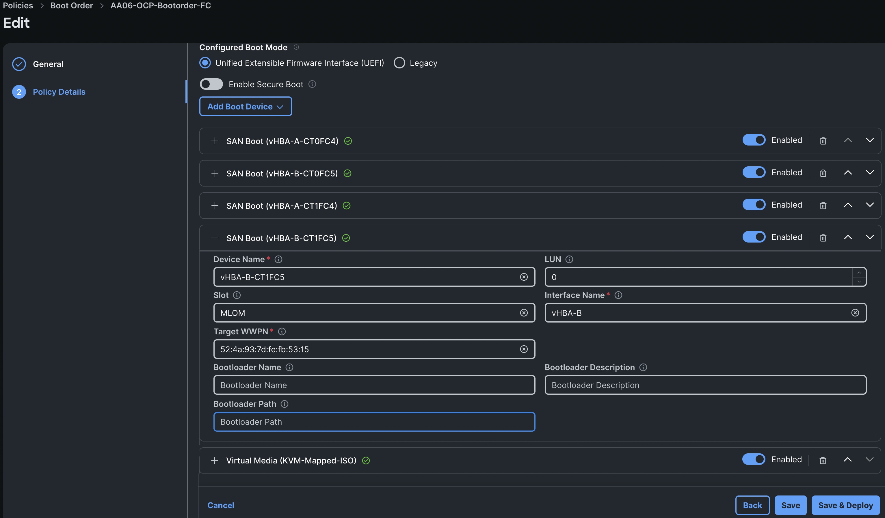
Virtual Media (vMedia) Policy
Virtual Media policy is used to mount the Red Hat CoreOS Discovery ISO to the server using CIMC Mapped DVD policy as previously explained.
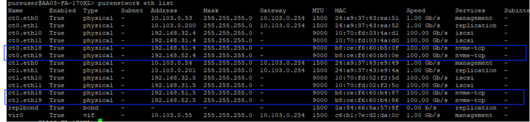
BIOS Policy
Create a BIOS policy by selecting pre-defined policy “Virtualization-M8-AMD” as shown below:
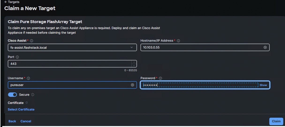
For more information about tunings for the AMD CPU BIOS, refer to : https://www.cisco.com/c/en/us/products/collateral/servers-unified-computing/ucs-c-series-rack-servers/ucs-c245-m8-rack-ser-4th-gen-amd-epyc-pro-wp.html
Firmware Policy
The following image shows the firmware versions used for each type of servers in this validation:
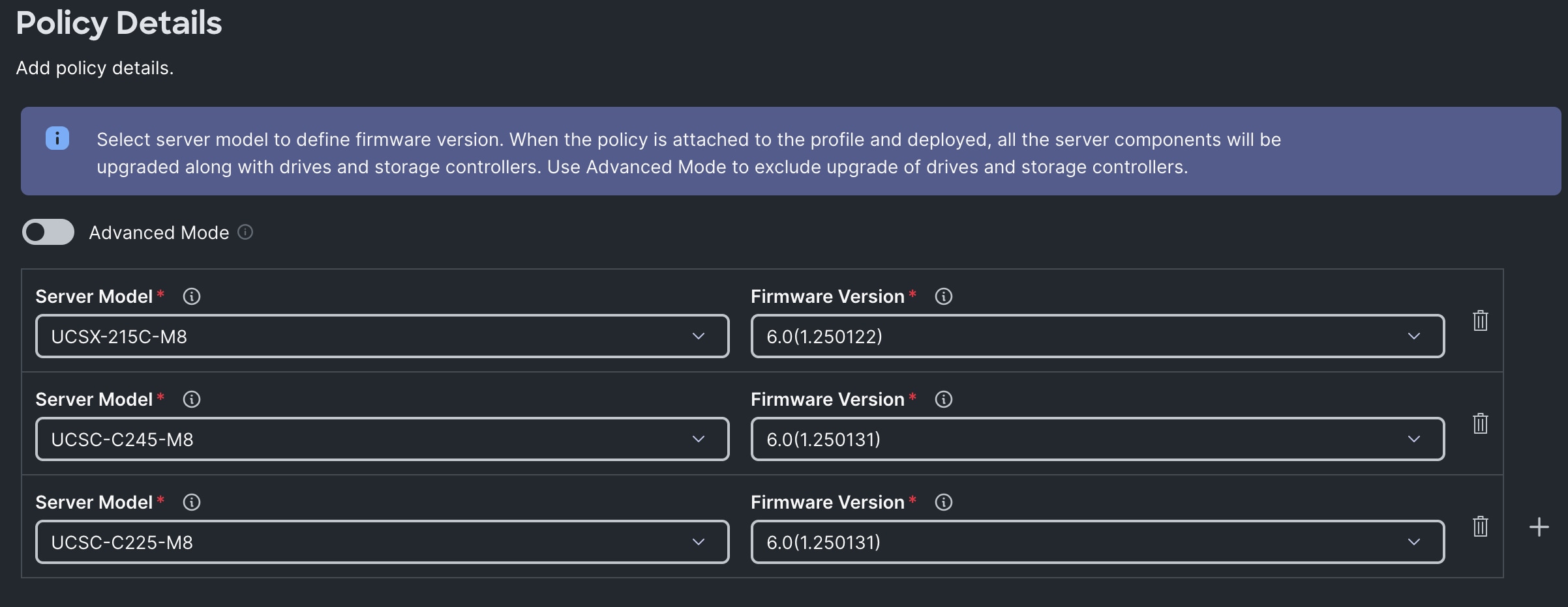
Power Policy
Create a Power Policy using the default values as shown below. Ensure to select UCS Server (FI-Attached) option.
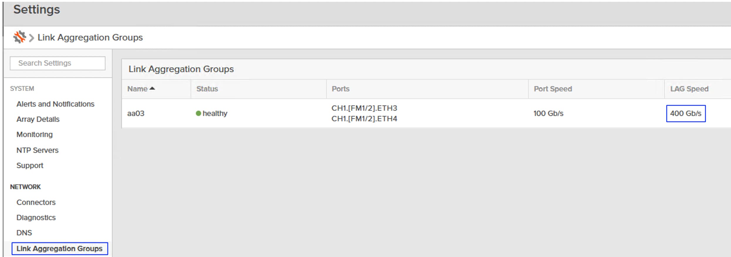
Management Configuration Policies
The following policies will be added to the management configuration:
● IMC Access to define the pool of IP addresses for compute node KVM access
● IPMI Over LAN to allow the servers to be managed by IPMI or redfish through the BMC or CIMC
● Local User to provide local administrator to access KVM
● Virtual KVM to allow the Tunneled KVM
Cisco IMC Access Policy
Create a CIMC Access Policy with settings as shown in the following screenshot.
Since certain features are not yet enabled for Out-of-Band Configuration (accessed using the Fabric Interconnect mgmt0 ports), you need to access the OOB-MGMT VLAN (1060) through the Fabric Interconnect Uplinks and mapping it as the In-Band Configuration VLAN.
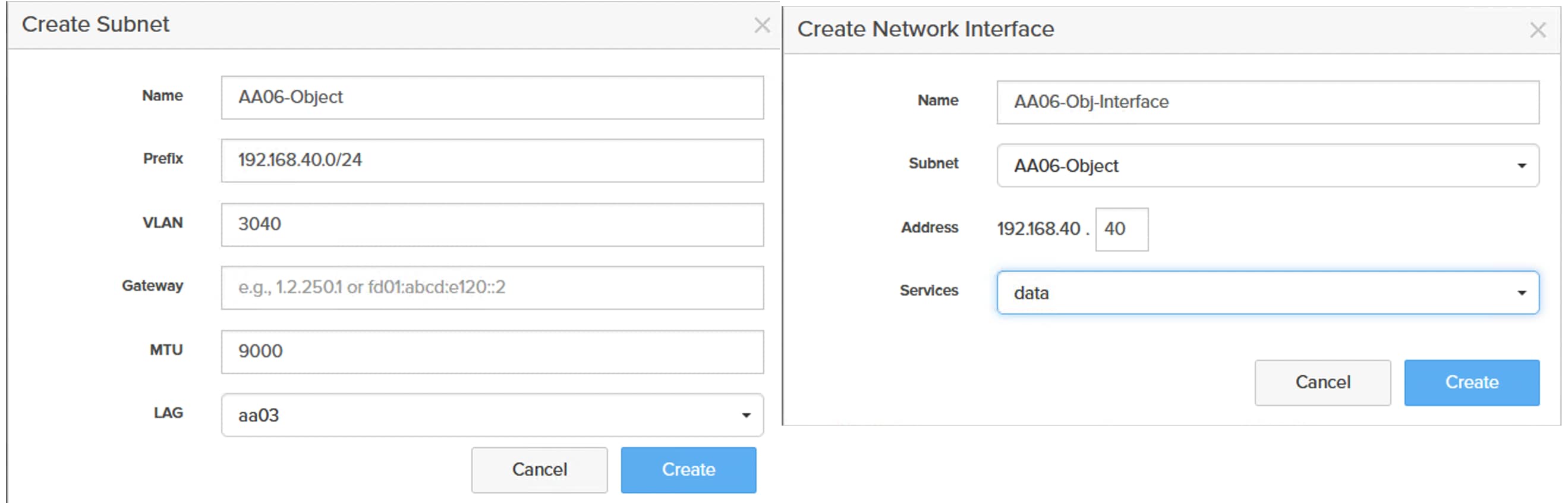
IPMI over LAN and Local User Policies
The IPMI Over LAN Policy can be used to allow both IPMI and Redfish connectivity to Cisco UCS Servers. Red Hat OpenShift platform uses these two policies to power manage (power off, restart, and so on) the OpenShift bare metal servers.
Create IPMI over LAN policy and Local User policies is shown below:
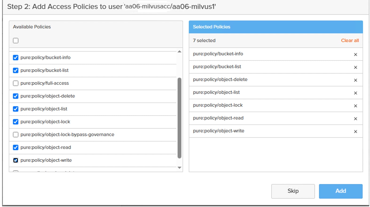
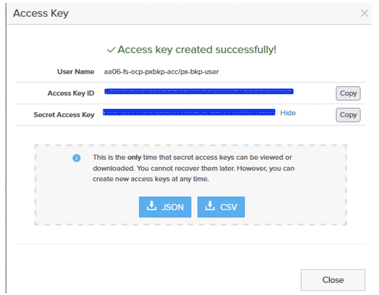
Virtual KVM Policy
The following image shows the virtual KVM policy used in the solution:
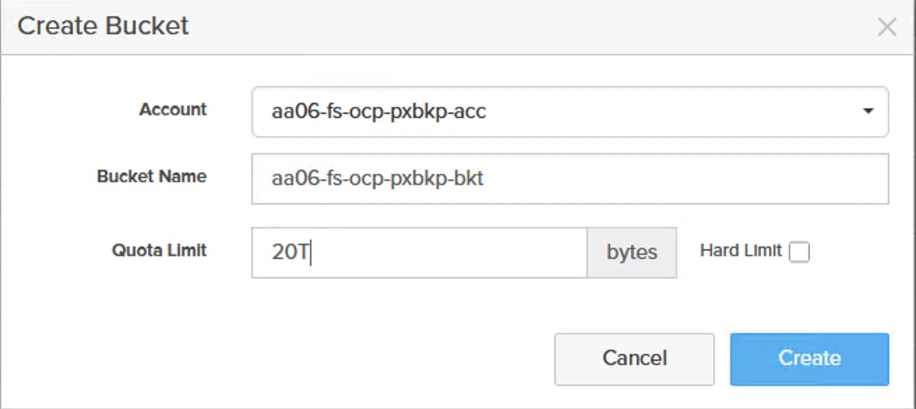
Create Server Profile Templates
When you have the required pools, polices, vNIC templates created, Server profile templates can be created. Single Server Profile Template is used for control plane and worker nodes.
Table 17 lists the policies and pools used to create the Server Profile template (AA06-OCPM2Boot-Worker-M8AMD) for IP and FC-based FlashStack Design.
Table 17. Policies and Pools used for IP-Based FlashStack DesControl Nodes
| Page Name |
Setting |
| General |
Name: AA06-OCPM2Boot-Worker-M8AMD/AA06-OCP-AMDM8_FCBoot |
| Compute Configuration |
UUID: AA06-OCP-UUIDPool BIOS: AA06-OCP-AMD-BIOS Boot Order: AA06-OCP-BootOrder-M2 OR AA06-OCP-BootOrder-FC Firmware: AA06-OCP-FWAMDM8 Power: AA06-OCP-ServerPower Virtual Media: CIMCMap-ISO-vMedia |
| Management Configuration |
IMC Access: AA06-OCP-IMC-AccessPolicy IPMI Over LAN: AA06-OCP-IPMoverLAN Local User: AA06-OCP-IMCLocalUser Virtual KVM: AA06-OCP-VitrualKVM |
| Storage Configuration |
Storage: AA06-OCP-Storage-M2R1 (Optional for FC-based Design) |
| Network Configuration |
LAN Connectivity: AA06-OCP-Worker-LANConn_AMD/ AA06-OCP-Worker-LANConn_AMD_FCSAN |
| SAN Configuration |
SAN Connectivity: AA06-OCP-SANConn_AMD (only for FC-based Design) |
The following images show the server profile templates created for the control and worker nodes for IP and FC -Based Designs:
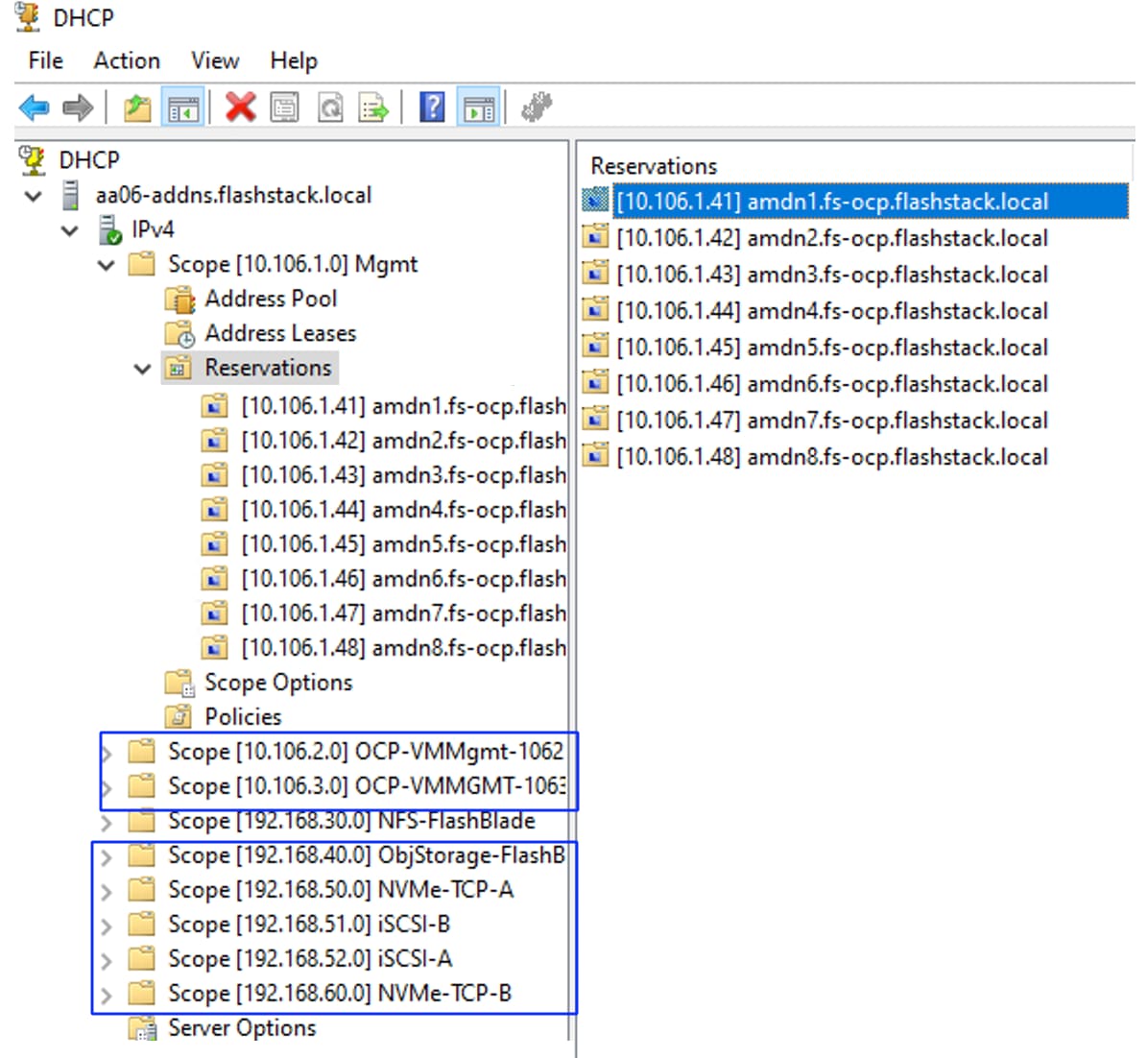
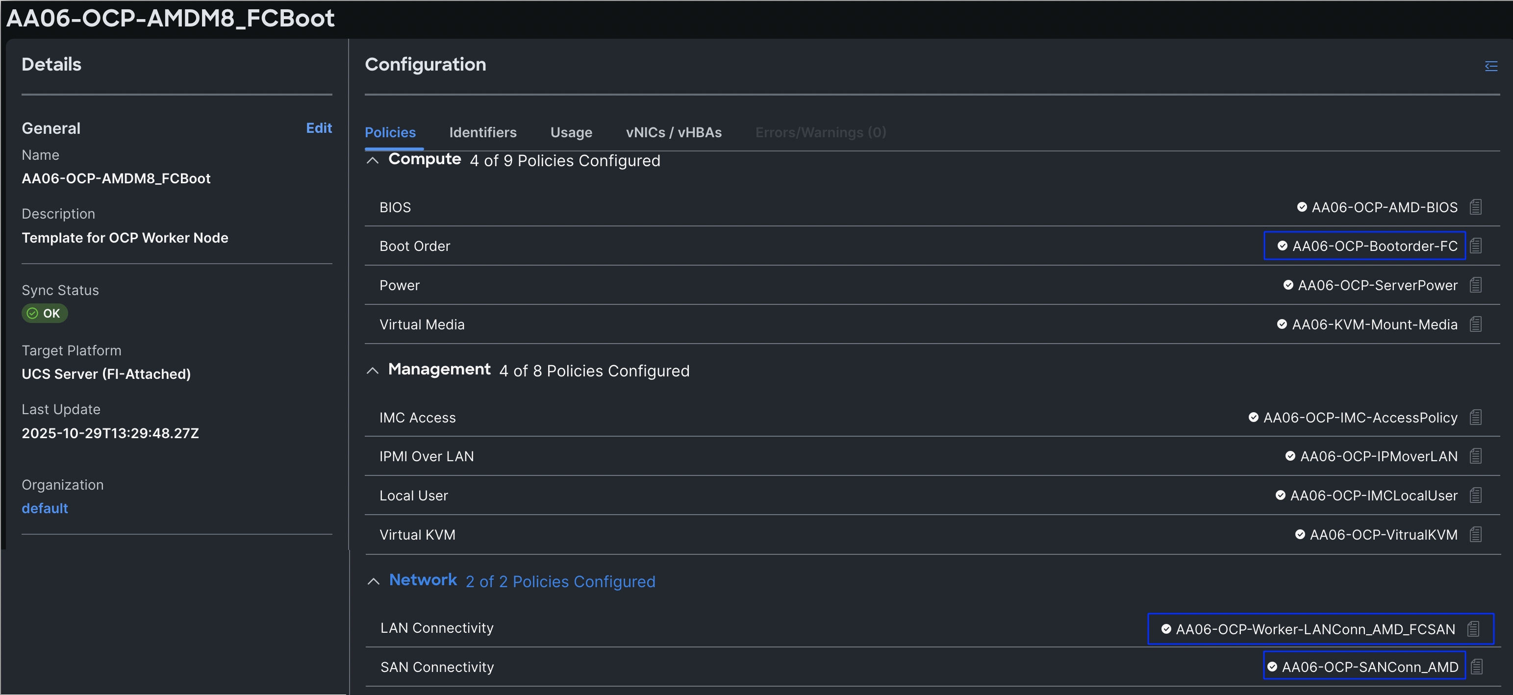
Create Server Profiles
Once Server Profile Templates are created, the server profiles can be derived from the template. The following screenshot shows a total of eight server profiles derived (three for control nodes and five for worker nodes).
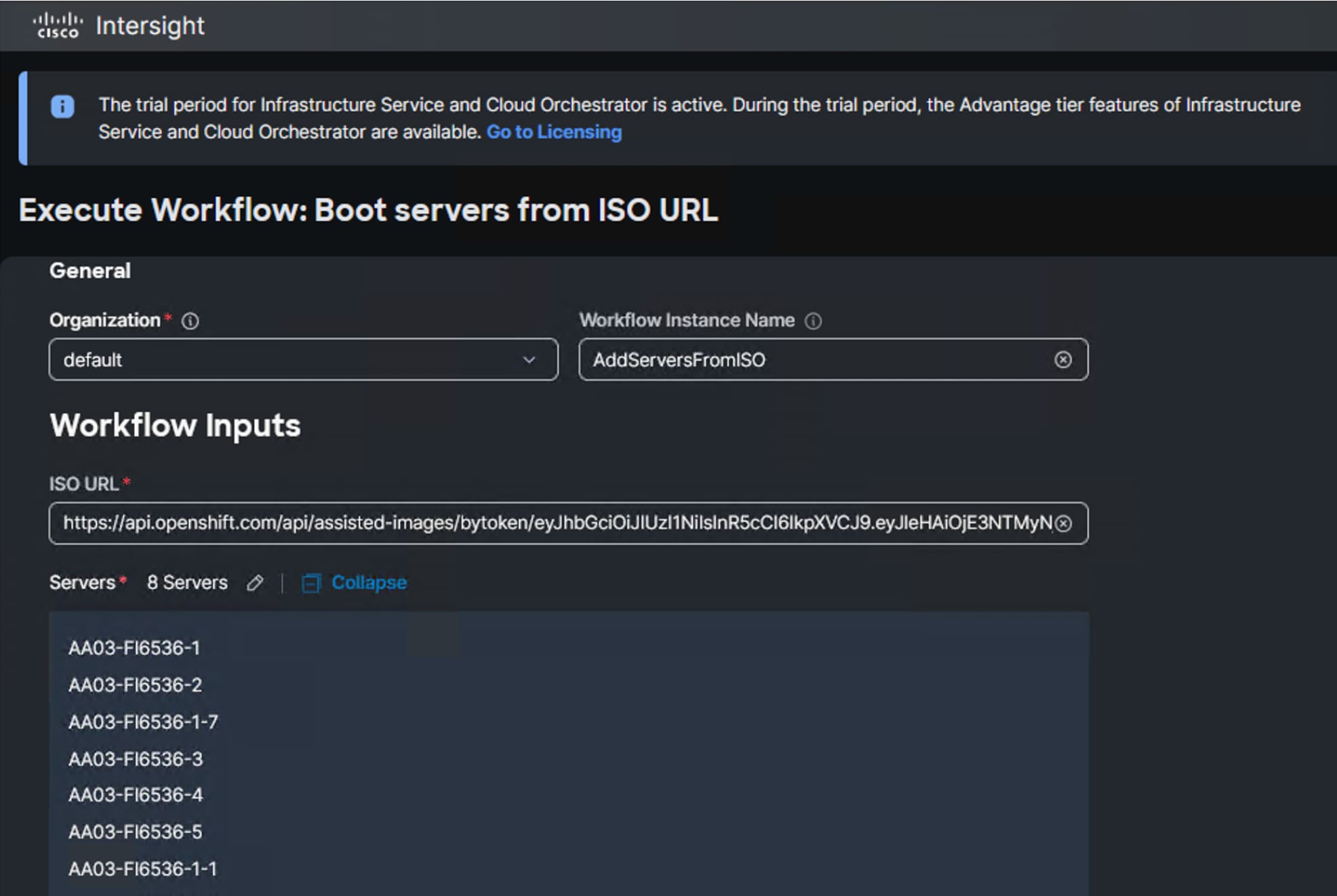
When the Server profiles are created, associate these server profiles to the control and workers nodes as shown below:
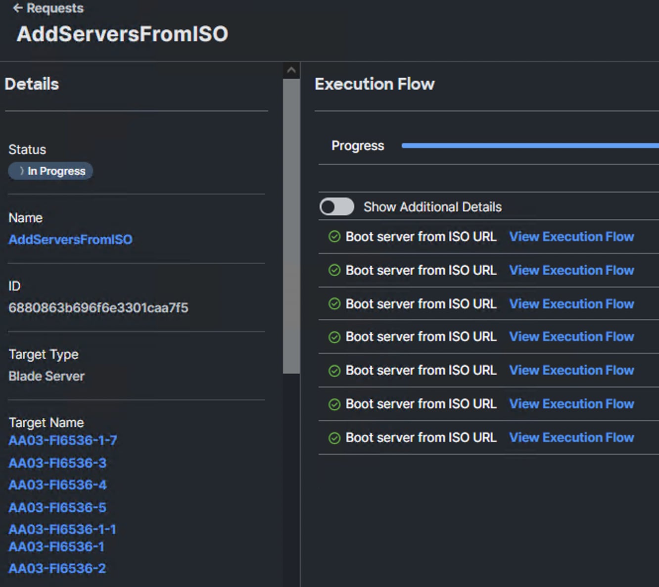
FC-based deployment, gather WWPN IDs for each host by clicking the server profile > vNICs/vHBAs as shown below. These WWPNs are required for zoning in MDS switches and granting access to the Boot volume in the FlashArray.
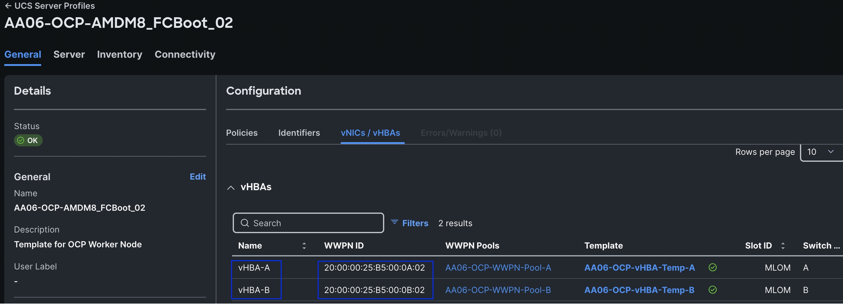
The following information is required to be gathered before MDS switches and creating Boot volumes later in the following sections:
Table 18. WWPNs of Compute nodes for FC Storage Access
| Profile Name |
WWPN of vHBA-A and vHBA-B |
| AA06-OCP-AMDM8_FCBoot_01 |
20:00:00:25:B5:00:0A:01, 20:00:00:25:B5:00:0B:01 |
| AA06-OCP-AMDM8_FCBoot_02 |
20:00:00:25:B5:00:0A:02, 20:00:00:25:B5:00:0B:02 |
| AA06-OCP-AMDM8_FCBoot_03 |
20:00:00:25:B5:00:0A:03, 20:00:00:25:B5:00:0B:03 |
| AA06-OCP-AMDM8_FCBoot_04 |
20:00:00:25:B5:00:0A:04, 20:00:00:25:B5:00:0B:04 |
| AA06-OCP-AMDM8_FCBoot_05 |
20:00:00:25:B5:00:0A:05, 20:00:00:25:B5:00:0B:05 |
| AA06-OCP-AMDM8_FCBoot_06 |
20:00:00:25:B5:00:0A:06, 20:00:00:25:B5:00:0B:06 |
| AA06-OCP-AMDM8_FCBoot_07 |
20:00:00:25:B5:00:0A:07, 20:00:00:25:B5:00:0B:07 |
| AA06-OCP-AMDM8_FCBoot_08 |
20:00:00:25:B5:00:0A:08, 20:00:00:25:B5:00:0B:08 |
Cisco MDS 9132T Switch Manual Configuration
Note: This document assumes that initial day-0 switch configuration is already done using switch console ports and ready to use the switches using their management IPs.
Procedure 1. Enable features on Cisco MDS A and Cisco MDS B
Step 1. Log into both MDS switches as admin using ssh.
Step 2. Enable the switch features as described below:
config terminal
feature npiv
feature fport-channel-trunk
feature scp-server
feature telemetry
feature nxapi
feature analytics
Procedure 2. Configure Individual Ports on each Switch
Step 1. Log into MDS Switch-A as admin using ssh.
Step 2. Run the following commands to configure the individual ports and port channels, and so on:
interface fc1/1
switchport description AA06-FI6536-A-36-1to4
port-license acquire
channel-group 203 force
no shutdown
interface fc1/2
switchport description AA06-FI6536-A-36-1to4
port-license acquire
channel-group 203 force
no shutdown
interface fc1/3
switchport description AA06-FI6536-A-36-1to4
port-license acquire
channel-group 203 force
no shutdown
interface fc1/4
switchport description AA06-FI6536-A-36-1to4
port-license acquire
channel-group 203 force
no shutdown
##configure FlashArray ports
interface fc1/5
analytics type fc-scsi
switchport description XL170-CT0fc4
switchport trunk mode off
port-license acquire
no shutdown
interface fc1/6
analytics type fc-scsi
switchport description XL170-CT1fc4
switchport trunk mode off
port-license acquire
no shutdown
interface fc1/7
analytics type fc-nvme
switchport description XL170-CT0fc6
switchport trunk mode off
port-license acquire
no shutdown
interface fc1/8
analytics type fc-nvme
switchport description XL170-CT1fc6
switchport trunk mode off
port-license acquire
no shutdown
interface port-channel203
switchport trunk allowed vsan 103
switchport description AA06-FI56536-A
switchport speed 32000
switchport rate-mode dedicated
Step 3. Log into MDS Switch-B as admin using ssh.
Step 4. Run the following commands to configure the individual ports and port channel, and so on:
interface fc1/1
switchport description AA06-FI6536-B-36-1to4
port-license acquire
channel-group 204 force
no shutdown
interface fc1/2
switchport description AA06-FI6536-B-36-1to4
port-license acquire
channel-group 204 force
no shutdown
interface fc1/3
switchport description AA06-FI6536-B-36-1to4
port-license acquire
channel-group 204 force
no shutdown
interface fc1/4
switchport description AA06-FI6536-B-36-1to4
port-license acquire
channel-group 204 force
no shutdown
##configure FlashArray ports
interface fc1/5
analytics type fc-scsi
switchport description XL170-CT0fc5
switchport trunk mode off
port-license acquire
no shutdown
interface fc1/6
analytics type fc-scsi
switchport description XL170-CT1fc5
switchport trunk mode off
port-license acquire
no shutdown
interface fc1/7
analytics type fc-nvme
switchport description XL170-CT0fc7
switchport trunk mode off
port-license acquire
no shutdown
interface fc1/8
analytics type fc-nvme
switchport description XL170-CT1fc7
switchport trunk mode off
port-license acquire
no shutdown
interface port-channel204
switchport trunk allowed vsan 104
switchport description AA06-FI56536-B
switchport speed 32000
Procedure 3. Create VSAN & Device Aliases on each Switch
Step 1. Log into MDS Switch-A and B as admin using ssh.
Step 2. Run the following commands to configure the VSAN and device aliases:
vsan database
vsan 103
vsan 103 name Fabric-A
exit
zone smart-zoning enable vsan 103
vsan database
vsan 103 interface port-channel201
vsan 103 interface fc1/1
vsan 103 interface fc1/2
vsan 103 interface fc1/3
vsan 103 interface fc1/4
exit
#### create following device Aliases
device-alias mode enhanced
device-alias database
device-alias name FA170-CT0FC4_scsi pwwn 52:4A:93:7D:FE:FB:53:04
device-alias name FA170-CT1FC4_scsi pwwn 52:4A:93:7D:FE:FB:53:14
device-alias name FA170-CT0FC6_nvme pwwn 52:4A:93:7D:FE:FB:53:06
device-alias name FA170-CT1FC6_nvme pwwn 52:4A:93:7D:FE:FB:53:16
device-alias name amdn1-a pwwn 20:00:00:25:B5:00:0A:01
device-alias name amdn2-a pwwn 20:00:00:25:B5:00:0A:02
device-alias name amdn3-a pwwn 20:00:00:25:B5:00:0A:03
device-alias name amdn4-a pwwn 20:00:00:25:B5:00:0A:04
device-alias name amdn5-a pwwn 20:00:00:25:B5:00:0A:05
device-alias name amdn6-a pwwn 20:00:00:25:B5:00:0A:06
device-alias name amdn7-a pwwn 20:00:00:25:B5:00:0A:07
device-alias name amdn8-a pwwn 20:00:00:25:B5:00:0A:08
device-alias commit
########## on MDS Switch B
vsan database
vsan 104
vsan 104 name Fabric-B
exit
zone smart-zoning enable vsan 104
vsan database
vsan 103 interface port-channel202
vsan 103 interface fc1/1
vsan 103 interface fc1/2
vsan 103 interface fc1/3
vsan 103 interface fc1/4
exit
#### create following device Aliases
device-alias mode enhanced
device-alias database
device-alias name FA170-CT0FC5_scsi pwwn 52:4A:93:7D:FE:FB:53:05
device-alias name FA170-CT1FC5_scsi pwwn 52:4A:93:7D:FE:FB:53:15
device-alias name FA170-CT0FC7_nvme pwwn 52:4A:93:7D:FE:FB:53:07
device-alias name FA170-CT1FC7_nvme pwwn 52:4A:93:7D:FE:FB:53:17
device-alias name amdn1-b pwwn 20:00:00:25:B5:00:0B:01
device-alias name amdn2-b pwwn 20:00:00:25:B5:00:0B:02
device-alias name amdn3-b pwwn 20:00:00:25:B5:00:0B:03
device-alias name amdn4-b pwwn 20:00:00:25:B5:00:0B:04
device-alias name amdn5-b pwwn 20:00:00:25:B5:00:0B:05
device-alias name amdn6-b pwwn 20:00:00:25:B5:00:0B:06
device-alias name amdn7-b pwwn 20:00:00:25:B5:00:0B:07
device-alias name amdn8-b pwwn 20:00:00:25:B5:00:0B:08
device-alias commit
Procedure 4. Create Zones and Zonesets
Step 1. Log into MDS Switch-A and B as admin using ssh.
Step 2. Run the following commands to configure the individual zones and zoneset and so on:
##Zone, Zoneset configuration for Switch-A
zone name amdn1-a vsan 103
member device-alias amdn1-a init
member device-alias FA170-CT0FC4_scsi target
member device-alias FA170-CT1FC4_scsi target
zone name amdn2-a vsan 103
member device-alias amdn2-a init
member device-alias FA170-CT0FC4_scsi target
member device-alias FA170-CT1FC4_scsi target
zone name amdn3-a vsan 103
member device-alias amdn3-a init
member device-alias FA170-CT0FC4_scsi target
member device-alias FA170-CT1FC4_scsi target
## Repeat the zones for 8 hosts
zone name amdn8-a vsan 103
member device-alias amdn8-a init
member device-alias FA-XL-CT0-Port-5-SCSI target
member device-alias FA-XL-CT1-Port-14-SCSI target
## Create Zoneset and add the zones
zoneset name Fabric-A vsan 103
member amdn1-a
member amdn2-a
member amdn3-a
member amdn8-a
zoneset activate name Fabric-A VSAN 103
show zoneset active
copy r s
##Zone, Zoneset configuration for Switch-B
zone name amdn1-b vsan 104
member device-alias amdn1-b init
member device-alias FA170-CT0FC5_scsi target
member device-alias FA170-CT1FC5_scsi target
zone name amdn2-b vsan 104
member device-alias amdn2-b init
member device-alias FA170-CT0FC5_scsi target
member device-alias FA170-CT1FC5_scsi target
zone name amdn3-b vsan 104
member device-alias amdn3-b init
member device-alias FA170-CT0FC5_scsi target
member device-alias FA170-CT1FC5_scsi target
## Repeat the zones for 8 hosts
zone name amdnb-a vsan 104
member device-alias amdn8-b init
member device-alias FA170-CT0FC5_scsi target
member device-alias FA170-CT1FC5_scsi target
## Create Zoneset and add the zones
zoneset name Fabric-B vsan 104
member amdn1-b
member amdn2-b
member amdn3-b
member amdn8-b
zoneset activate name Fabric-B VSAN 104
show zoneset active
copy r s
Create Boot Volumes for SAN Boot
Once the required vHBAs configuration and zone configuration is completed on the hosts and switches, Boot volumes can be created and mapped to the corresponding hosts in the FlashArray. Follow the below steps to create Hosts, Boot volumes and attach Boot volumes to the Hosts with in the FlashArray//XL170.
Procedure 1. Create Hosts with WWPN
Step 1. Log into both Pure Storage FlashArray with admin credentials.
Step 2. Click the Storage tab > Hosts > click the + symbol to create a host(s). Click Create Multiple to create multiple hosts at a time. Provide a name (amdn-#), set start Number to 1, count to 8 and Number of Digits to 1 and click Create. Ignore Add HostGroup option when it is prompted.
Step 3. Click the newly created host > click the + symbol under Host Ports and select Configure WWNs.
Step 4. Click the + symbol and provide WWPN of the host from vHBA-A and vHBA-B by referring to Table 18. Repeat this steps for all the hosts.
Step 5. Click Storage > Volumes tab, click the + to create boot volumes. Click Create Multiple to create multiple boot volumes at a time. Provide a name (amdn-#-bootvol), set size to 1024GB, set start Number to 1, count to 8 and Number of Digits to 1 and click Create.
Step 6. Click each volume, click the + under Connect Hosts box, click Connect. Select the corresponding host name from the available host list and click Connect.
Step 7. Power on each host and connect to one of the KVM console of a host. If it is configured correctly, the host will be able to detect the boot volume with four paths as shown below:
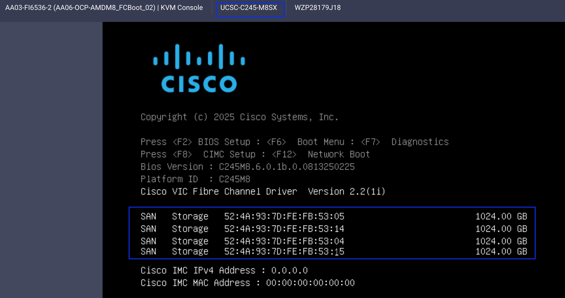
Now the Cisco UCS AMD M8 servers are ready for the OpenShift installation.
Pure Storage FlashBlade Configuration
This chapter contains the following:
In this solution, Pure Storage FlashBlade//S200 is used as the S3 compliant on-prem object storage provider for the PX-Backup as explained in the previous sections. The FlashBlade is directly accessed by the PX-Backup pods by using Workers node’s interface that carries object storage traffic (eno11). This section describes high-level steps to configure Pure Storage FlashBlade//S200 network interfaces required for storage connectivity over ethernet.
The FlashBlade//S200 provides up to 8x 100GbE interfaces for data traffic. In this solution, 2x 100GbE from each FIOM (with aggregated network bandwidth of 400 GbE) are connected to a pair of Nexus switches.
Note: This document is not intended to explain every day-0 initial configuration steps to bring the array up and running. For day-0 configuration steps, see: https://support.purestorage.com/bundle/m_flashblades/page/FlashBlade/FlashBlade_Hardware/topics/concept/c_flashblades.html
Table 19 lists the IP addressing configured on the interfaces used for objects storage access.
Table 19. Link Aggregation Groups (LAG)
| LAG Name |
FM |
Ethernet Ports |
| AA03 |
1 |
CH1. FM1.ETH3 and CH1. FM1.ETH4 |
| 2 |
CH1. FM2.ETH3 and CH1. FM2.ETH4 |
A Link Aggregation Group is created using CH1.FM1.ETH3, CH1.FM1.ETH4, CH1.FM2.ETH3, and CH1.FM2.ETH4 interfaces as shown below. Notice that the aggregated bandwidth of the LAG is 400GbE as it is created with 4x 100GbE interfaces as shown below:
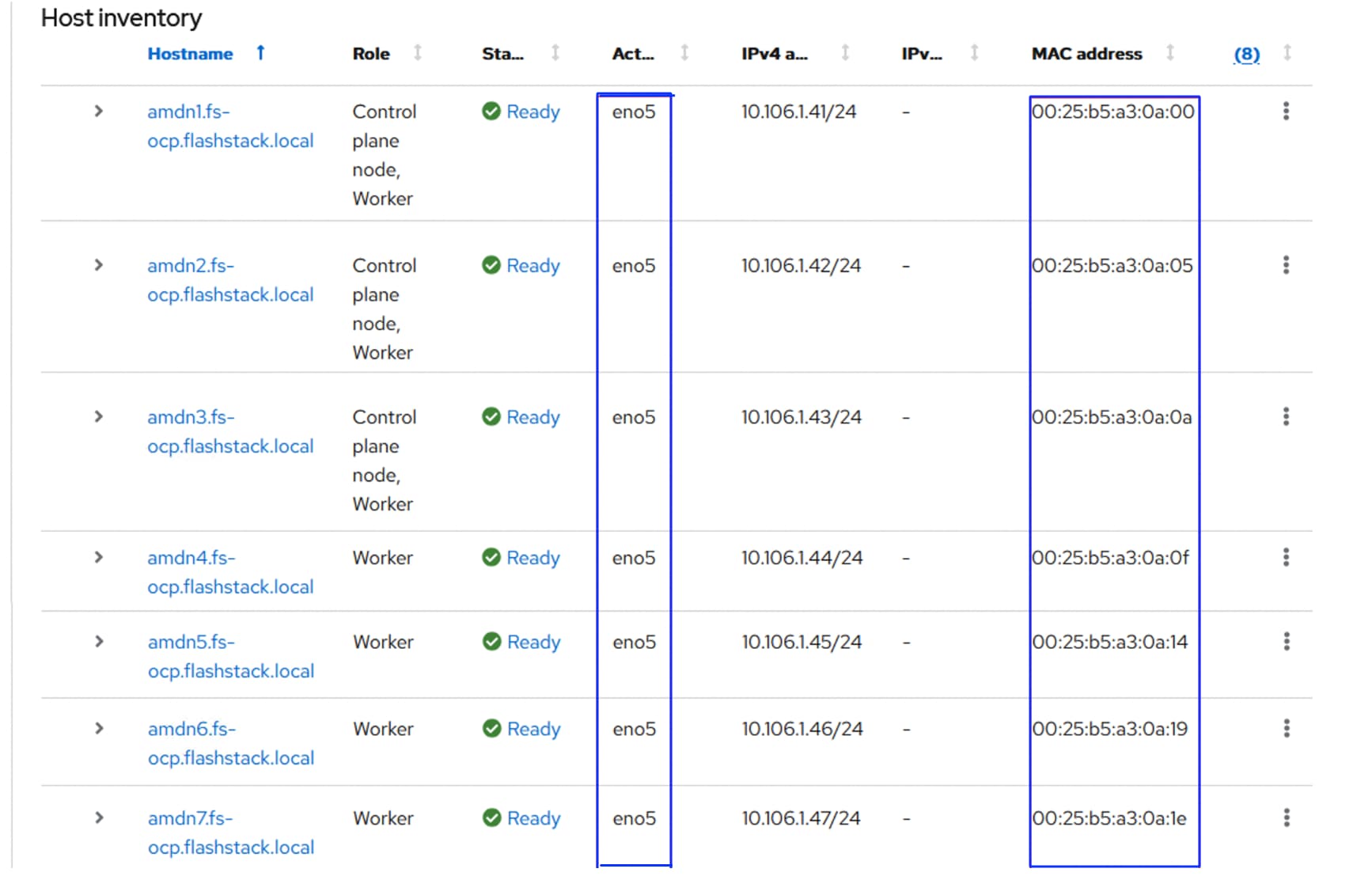
Once the LAG is created, a Subnet (AA06-Object) and an interface (AA06-Obj-Interface) are created as shown below. For the subnet, ensure to set MTU as 9000, VLAN as 3040 and select aa03 for the LAG. Ensure to set Services as Data for the interface.
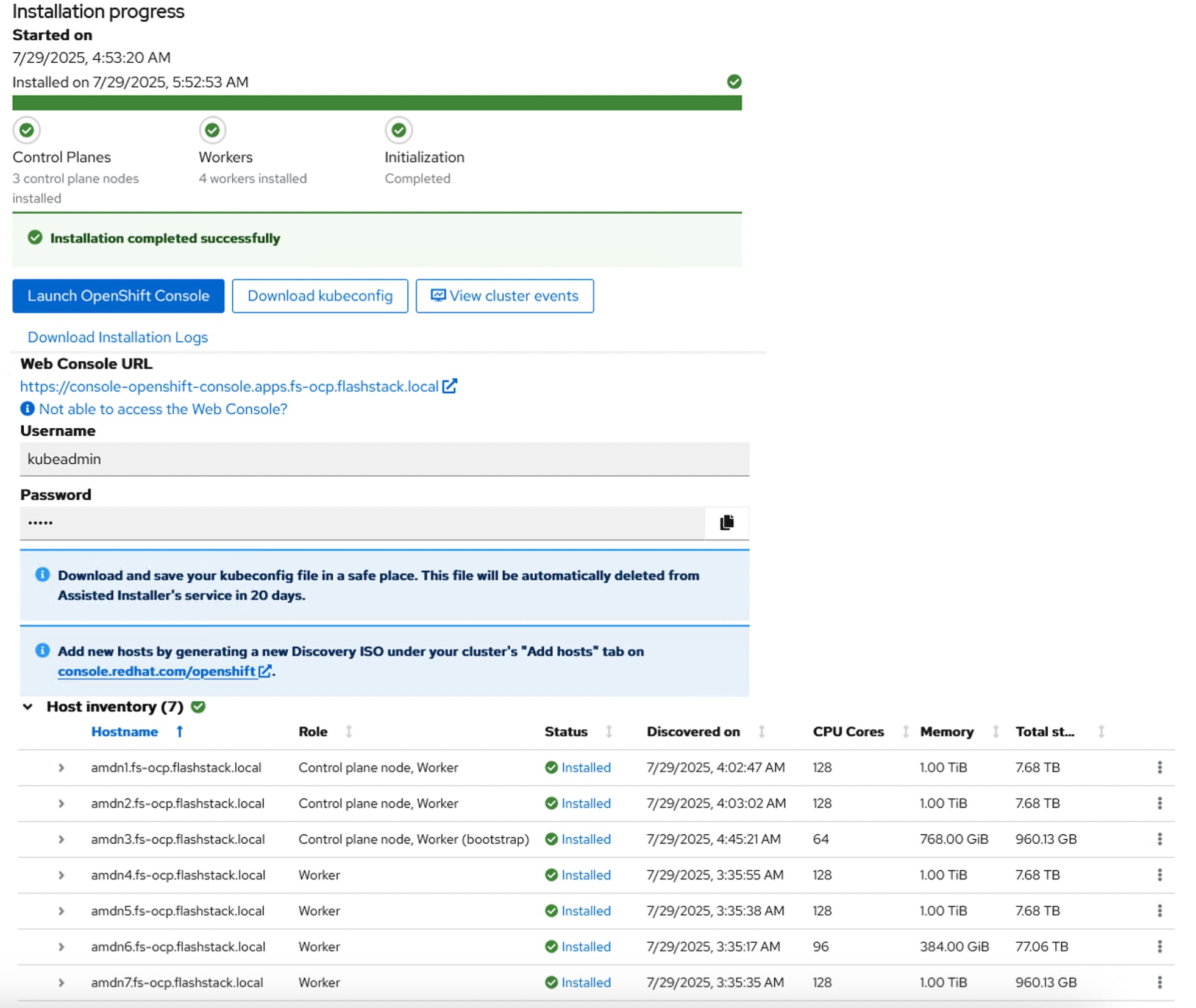
FlashBlade Object Store configuration involves creating an Object Store Account, User, Access Keys and a Bucket.
Procedure 1. Create Object Store Account, User, Access Keys and Bucket
Step 1. Log into Pure FlashBlade//S200 using its management IP addresses.
Step 2. Click Storage > Object Store > Accounts > Click + to create an account.
Step 3. Provide a name for Account, Quota Limit and Bucket Default Quota Limit as per your requirements. Click Create.
Step 4. Click the newly created Account name and click + to create a new user for the account.
Step 5. Provide a username and click Create.
Step 6. In the Add Access Policies window, select the pre-defined access policies as shown below. Or create your own access policy with a set of rules and finally select it.
Step 7. Click Add when Access Policy is selected.
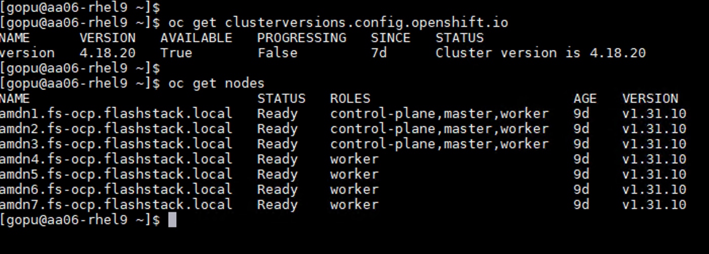
Step 8. Click Create a new key and click Create to create a pair of access and secret keys. Preserve the Access and Secret Keys for later use. Click Close.
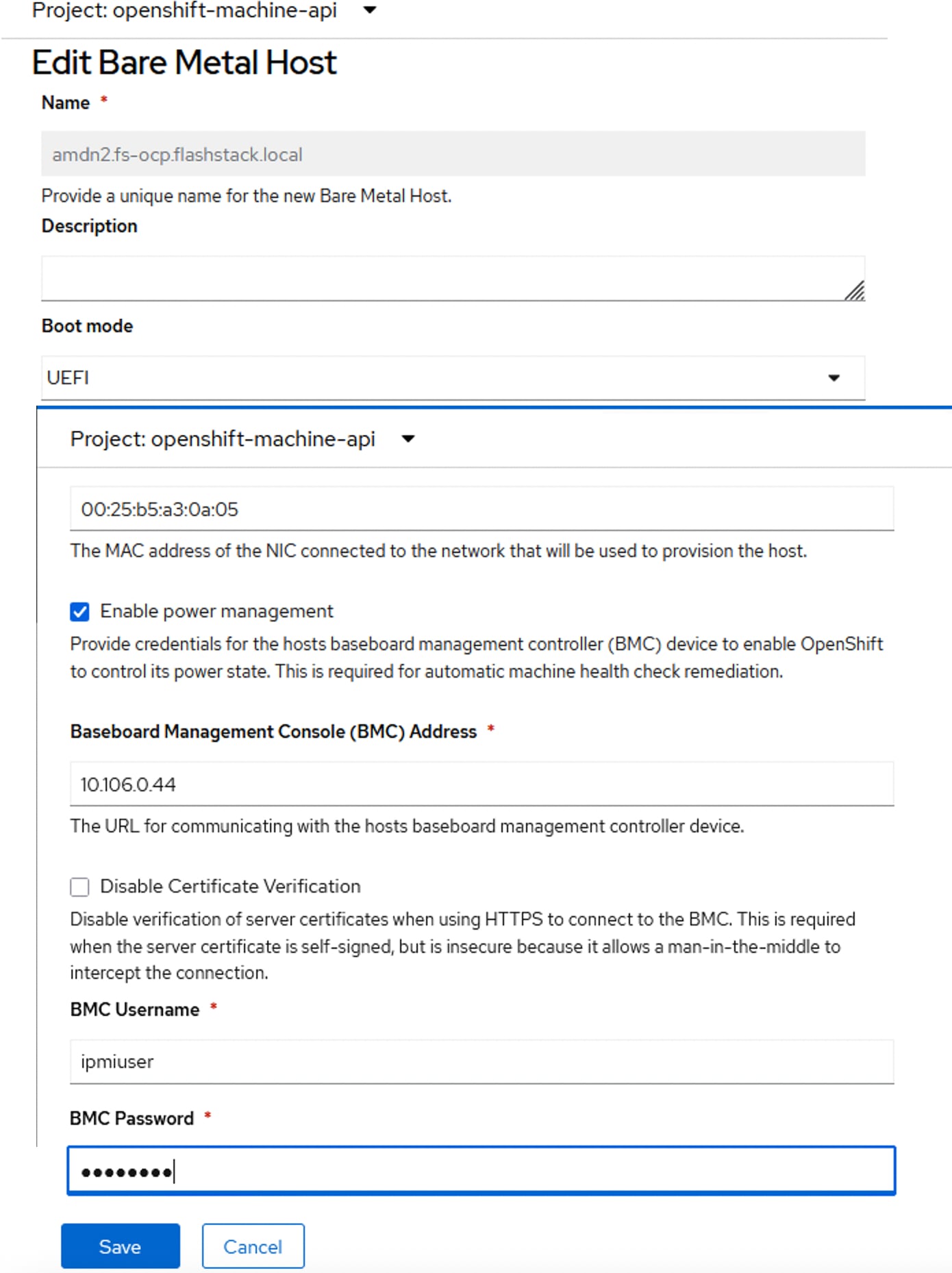
Step 9. Ensure you note and backup the Access Key ID and Secret Access key as you need these details to configure the PX-Backup.
Step 10. Click Account name and go to the Buckets sections. Click + to create a bucket and add it to the account.
Step 11. Select the account created in the previous step and input values for Bucket Name and Quota Limit. Click Create.
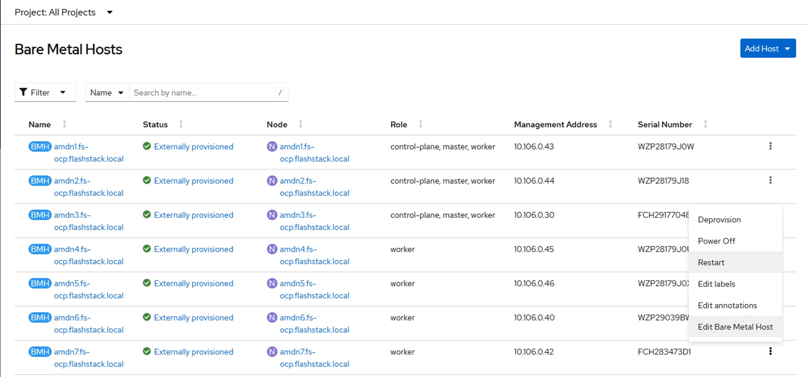
OpenShift Installation and Configuration
This chapter contains the following:
● OpenShift Container Platform – Installation Requirements
OpenShift v4.18 is deployed on Cisco UCS infrastructure as M.2 booted bare metal servers. The Cisco UCS AMD M8 servers need to be equipped with an M.2 controller (SATA or NVMe) card, and two identical M.2 drives. Three control plane nodes and four worker nodes are deployed in the validation environment and additional worker nodes can easily be added to increase the scalability of the solution. This document will guide you through the process of using the Assisted Installer to deploy OpenShift 4.18.
OpenShift Container Platform – Installation Requirements
The Red Hat OpenShift Assisted Installer provides support for installing OpenShift Container Platform on bare metal nodes. This guide provides a methodology to achieving a successful installation using the Assisted Installer.
The FlashStack for OpenShift utilizes the Assisted Installer for OpenShift installation. Therefore, when provisioning and managing the FlashStack infrastructure, you must provide all the supporting cluster infrastructure and resources, including an installer VM or host, networking, storage, and individual cluster machines.
The following supporting cluster resources are required for the Assisted Installer installation:
● The control plane and compute machines that make up the cluster
● Cluster networking
● Storage for the cluster infrastructure and applications
● The Installer VM or Host
The following infrastructure services need to be deployed to support the OpenShift cluster, during the validation of this solution we have provided VMs on your hypervisor of choice to run the required services. You can use the existing DNS and DHCP services available in the data center.
There are various infrastructure services prerequisites for deploying OpenShift 4.18. These prerequisites are as follows:
● DNS and DHCP services – these services were configured on Microsoft Windows Server VMs in this validation
● NTP Distribution was done with Nexus switches
● Specific DNS entries for deploying OpenShift – added to the DNS server
● A Linux VM for initial automated installation and cluster management – a Rocky Linux / RHEL VM with appropriate packages
NTP
Each OpenShift Container Platform node in the cluster must have access to at least two NTP servers.
NICs
NICs configured on the Cisco UCS servers based on the design previously discussed.
DNS
Clients access the OpenShift Container Platform cluster nodes over the bare metal network. Configure a subdomain or subzone where the canonical name extension is the cluster name.
The following domain and OpenShift cluster names are used in this deployment guide:
● Base Domain: flashstack.local
● OpenShift Cluster Name: fs-ocp
The DNS domain name for the OpenShift cluster should be the cluster name followed by the base domain, for example fs-ocp.flashstack.local.
Table 20 lists the information for fully qualified domain names used during validation. The API and Nameserver addresses begin with canonical name extensions. The hostnames of the control plane and worker nodes are exemplary, so you can use any host naming convention you prefer.
| Usage |
Hostname |
IP Address |
| API |
api.fs-ocp.flashstack.local |
10.106.1.39 |
| Ingress LB (apps) |
*.apps.fs-ocp.flashstack.local |
10.106.1.40 |
| amdn1 |
amdn1.fs-ocp.flashstack.local |
10.106.1.41 |
| amdn2 |
amdn2.fs-ocp.flashstack.local |
10.106.1.42 |
| amdn3 |
amdn3.fs-ocp.flashstack.local |
10.106.1.43 |
| amdn4 |
amdn4.fs-ocp.flashstack.local |
10.106.1.44 |
| amdn5 |
amdn5.fs-ocp.flashstack.local |
10.106.1.45 |
| amdn6 |
amdn6.fs-ocp.flashstack.local |
10.106.1.46 |
| amdn7 |
amdn7.fs-ocp.flashstack.local |
10.106.1.47 |
| amdn8 |
amdn8.fs-ocp.flashstack.local |
10.106.1.48 |
For initial deployment, only first seven nodes ( three control plane and four worker nodes) are used for OpenShift deployment. The last node amdn8.fs-ocp.flashstack.local will be added later as part of the cluster expansion by adding a new server node to the already existing cluster.
DHCP
For the bare metal network, a network administrator must reserve several IP addresses, including:
● One IP address for the API endpoint
● One IP address for the wildcard Ingress endpoint
● One IP address for each control node (DHCP server assigns to the node)
● One IP address for each worker node (DHCP server assigns to the node)
Note: Get the MAC addresses of the bare metal Interfaces from the UCS Server Profile for each node to be used in the DHCP configuration to assign reserved IP addresses (reservations) to the nodes. The KVM IP address also needs to be gathered for the control plane and worker nodes from the server profiles.
Procedure 1. Gather MAC Addresses of Node Bare Metal Interfaces
Step 1. Log into Cisco Intersight.
Step 2. Go to Infrastructure Service > Profiles > click any UCS Server Profile.
Step 3. In the center pane, go to Inventory > Network Adapters > Network Adapter.
Step 4. In the center pane, click Interfaces.
Step 5. Record the MAC address for NIC Interface eno5.
Step 6. Select the General tab and click Identifiers.
Step 7. Record the Management IP assigned from the AA06-OCP-OOB-MGMT-IP Pool.
Table 21 lists the IP addresses used for the OpenShift cluster including bare metal network IPs and UCS KVM Management IPs for IMPI or Redfish access.
Table 21. Host BMC Information
| Hostname |
Management IP Address |
UCS KVM Mgmt. IP Address |
BareMetal MAC Address (eno5) |
| amdn1.fs-ocp.flashstack.local |
10.106.1.41 |
10.106.0.43 |
00:25:B5:A3:0A:00 |
| amdn2.fs-ocp.flashstack.local |
10.106.1.42 |
10.106.0.44 |
00:25:B5:A3:0A:05 |
| amdn3.fs-ocp.flashstack.local |
10.106.1.43 |
10.106.0.30 |
00:25:B5:A3:0A:0A |
| amdn4.fs-ocp.flashstack.local |
10.106.1.44 |
10.106.0.45 |
00:25:B5:A3:0A:0F |
| amdn5.fs-ocp.flashstack.local |
10.106.1.45 |
10.106.0.46 |
00:25:B5:A3:0A:14 |
| amdn6.fs-ocp.flashstack.local |
10.106.1.46 |
10.106.0.40 |
00:25:B5:A3:0A:19 |
| amdn7.fs-ocp.flashstack.local |
10.106.1.47 |
10.106.0.42 |
00:25:B5:A3:0A:1E |
| amdn8.fs-ocp.flashstack.local |
10.106.1.48 |
10.106.0.41 |
00:25:B5:A3:0A:23 |
Step 8. From Table 21, enter the hostnames, IP addresses, and MAC addresses as reservations in your DHCP and DNS server(s) or configure the DHCP server to dynamically update DNS.
Step 9. You need to pipe VLAN interfaces for all three storage VLANs (3010, 3020 and 3040) and three management VLANs (1061,1062,1063) into your DHCP server(s) and assign IPs in the storage networks on those interfaces.
Step 10. Create a DHCP scope for each management and storage VLANs with the appropriate subnets.
Step 11. Ensure that the IPs assigned by the scope do not overlap with the already consumed IPs (like FlashArray//XL170 storage iSCSI interface IPs, FlashBlade//S200 interfaces and OpenShift reserved IPs).
Step 12. Either enter the nodes in the DNS server or configure the DHCP server to forward entries to the DNS server. For the cluster nodes, create reservations to map the hostnames to the desired IP addresses as shown in below:
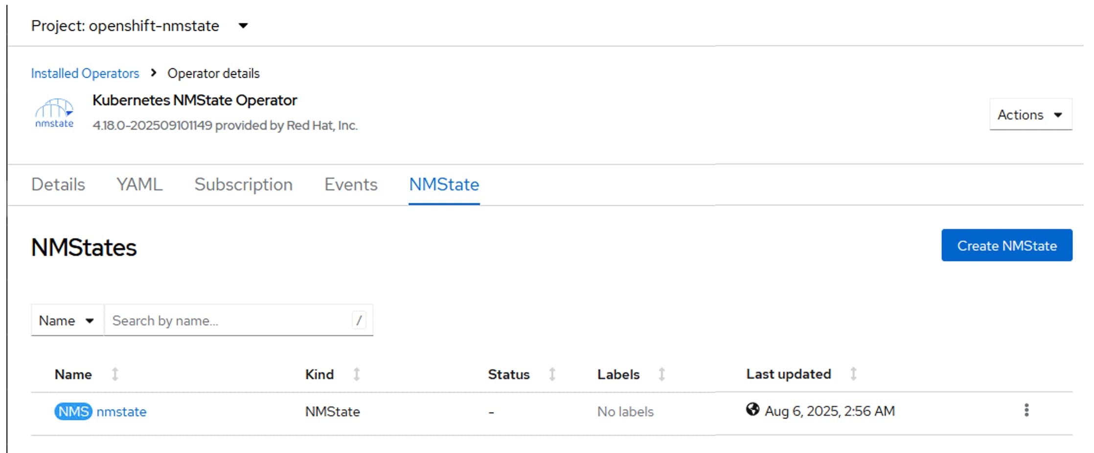
Note: With these DHCP scopes in place, the Management and storage IPs will be assigned automatically from the corresponding DHCP pools to the respective interfaces of control plane nodes and worker nodes. No manual IP configuration is required.
Step 13. Setup either a VM (installer/bastion node) or spare server with the network interface connected to the Host management VLAN (1061).
Step 14. Install either Red Hat Enterprise Linux (RHEL) 9.4 or Rocky Linux 9.4 Server with GUI and create an administrator user. Once the VM or host is up and running, update it and install and configure XRDP. Connect to this host with a Windows Remote Desktop client as the admin user.
Step 15. ssh into the installer node VM, open a terminal session and create an SSH key pair to use to communicate with the OpenShift hosts:
cd
ssh-keygen -t ed25519 -N '' -f ~/.ssh/id_ed25519
Step 16. Copy the public SSH key to the user directory:
cp ~/.ssh/id_ed25519.pub ~/
Step 17. Add the private key to the ssh-agent:
ssh-add ~/.ssh/id_ed25519
Procedure 2. Install Red Hat OpenShift Container Platform using the Assisted Installer
Step 1. Launch Firefox and connect to https://console.redhat.com/openshift/cluster-list. Log into your Red Hat account.
Step 2. Click Create cluster to create an OpenShift cluster.
Step 3. Select Datacenter and then select Bare Metal (x86_64).
Step 4. Select Interactive to launch the Assisted Installer.
Step 5. Provide the cluster name and base domain.
Step 6. Select the latest OpenShift version (4.18.20 or above), scroll down and click Next.
Step 7. Do not select the operator and click Next.
Step 8. Click Add hosts.
Step 9. Under Provisioning type, from the drop-down list select the Full Image file. Under SSH public key, click Browse and browse to, select, and open the id_ed25519.pub file. The contents of the public key should now appear in the box. Click Generate Discovery ISO. Now the Discovery ISO is ready for download. Click the Add Hosts from Cisco Intersight link to select the server list to boot them using Discovery ISO.
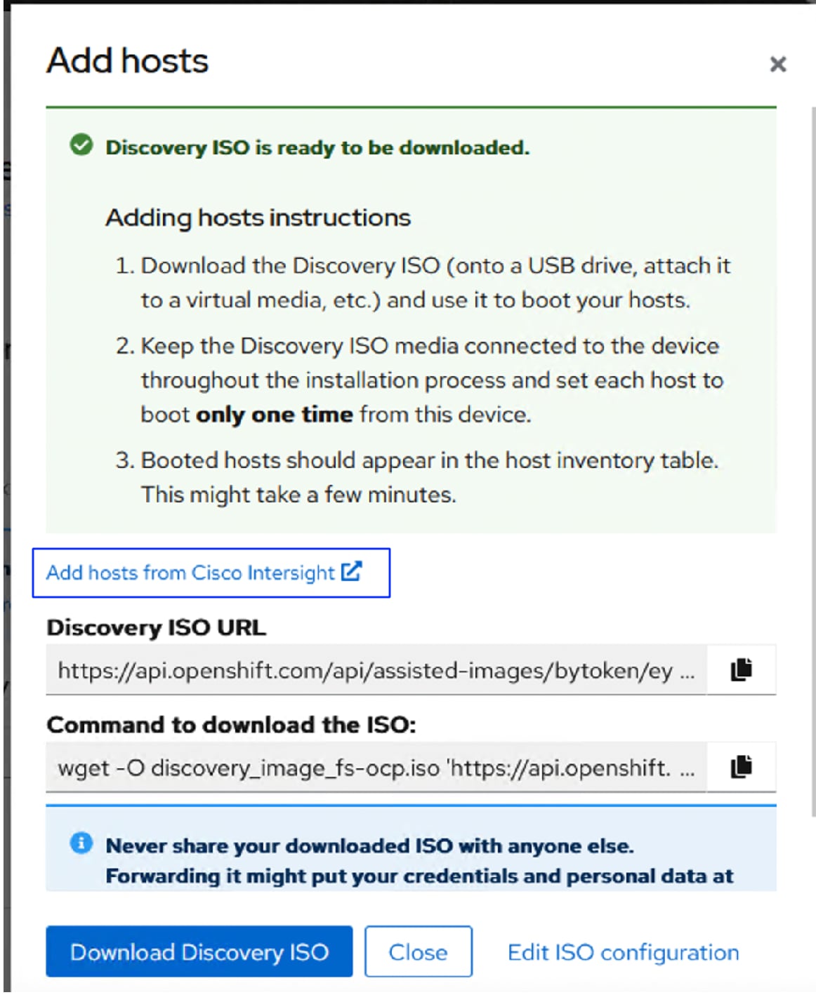
Step 10. A new Intersight workflow Boot server from ISO URL window appears. Click the pencil symbol and select the required servers and click Close.
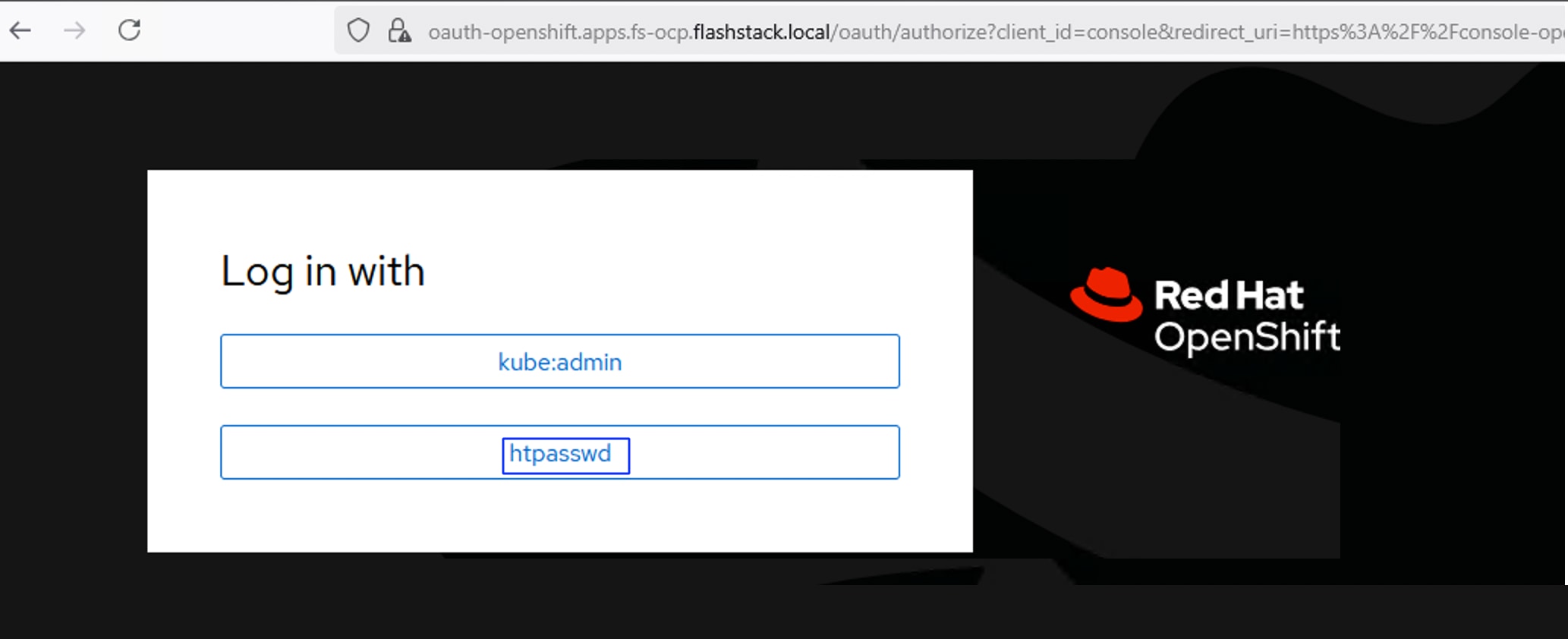
The Intersight workflow will be created to download the Discovery ISO, mount the ISO to the selected hosts, and boot them using the ISO. The workflow task details is shown below:

Step 11. Wait for all servers to boot and appear in the Red Hat Assisted installer console. The server will get names and IPs assigned from the DHCP reservations configured in the previous steps.
Step 12. Enable the Run workloads on the control plane nodes radio button to schedule workloads on the control plane nodes.
Step 13. From the drop-down list under Role assign the appropriate server roles. Scroll down and click Next. Configure the first nodes as control plane nodes and the rest as workers.
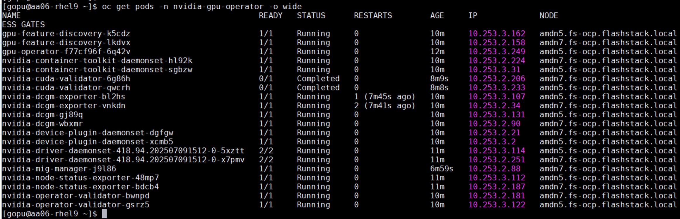
Step 14. Expand each node and confirm the role of the M.2 disk is set to Installation disk. Click Next.
Step 15. Under Network Management, make sure Cluster-Managed Networking is selected. Under Machine network, from the drop-down list, select the subnet for the host management network. Enter the IPs for API IP (api.fs-ocp.flashstack.local) and Ingress IP (*.apps.fs-ocp.flashstack.local).
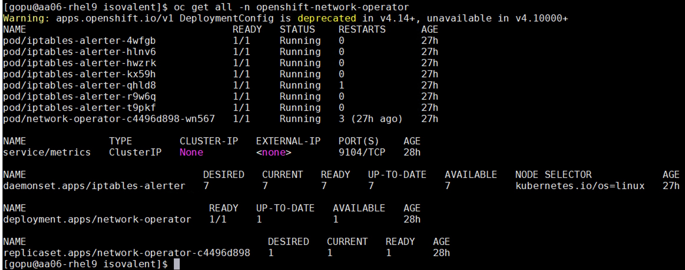
Note: If you see insufficient warning message for the nodes due to missing ntp server information, expand one of the nodes, click Add NTP Sources and provide the NTP servers IPs separated by a comma.
Note: If you see a warning message on each node having multiple network devices on the L2 network; SSH into each worker and deactivate interfaces from eno6 to eno11 using nmtui utility or nmcli command (“nmcli device disconnect <interface-name>”).
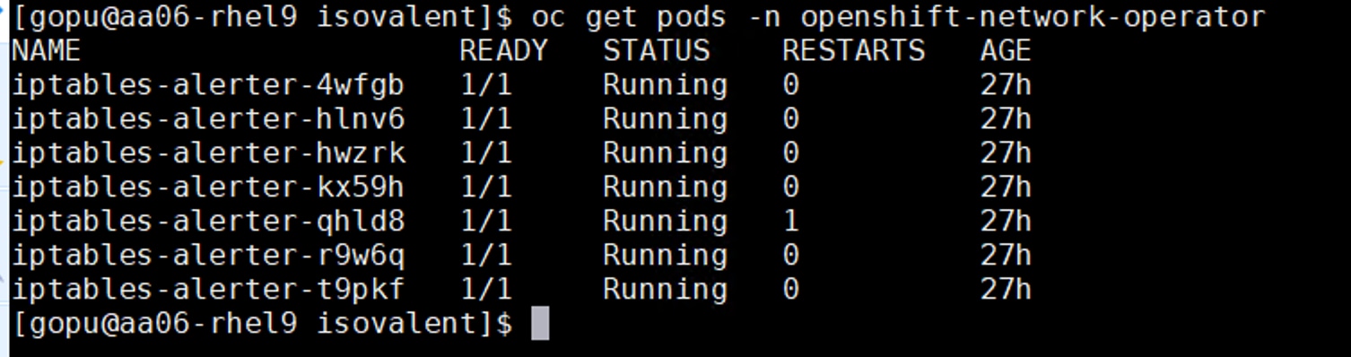
Step 16. When all the nodes are in ready status, click Next. Review all the settings and click Install Cluster. The OpenShift Cluster will be installed as shown below:
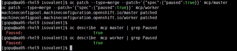
Step 17. Click Web Console URL to log into the newly created OpenShift cluster with kubeadmin user and verify the cluster settings.
Step 18. Once the cluster is installed, ensure to download the kubeconfig file. Upload the file Installer VM and from a terminal window, setup a cluster directory and save the kubeconfig credentials:
cd
mkdir <clustername> # for example, ocp
cd <clustername>
mkdir auth
cd auth
mv ~/Downloads/kubeconfig ./
mkdir ~/.kube
cp kubeconfig ~/.kube/config
Step 19. In the Assisted Installer, click the icon to copy the kubeadmin password:
echo <paste password> > ./kubeadmin-password
Step 20. Click Open console to launch the OpenShift Console. Log in using the kubeadmin and the kubeadmin password.
Step 21. Click the ? mask. Links for various tools are provided in that page. Download oc for Linux for x86_64 and virtctl for Linux for x86_64 Common Line Tools.
cd ..
mkdir client
cd client
ls ~/Downloads
mv ~/Downloads/oc.tar.gz ./
mv ~/Downloads/virtctl.tar.gz ./
tar xvf oc.tar
tar xvf virtctl.tar.gf
ls
sudo mv oc /usr/local/bin/
sudo mv virtcl /usr/local/bin/
sudo mv kubectl /usr/local/bin/
oc get nodes
Step 22. To enable oc tab completion for bash, run the following:
oc completion bash > oc_bash_completion
sudo mv oc_bash_completion /etc/bash_completion.d/
You should now be able to use oc to fetch the OpenShift node details:
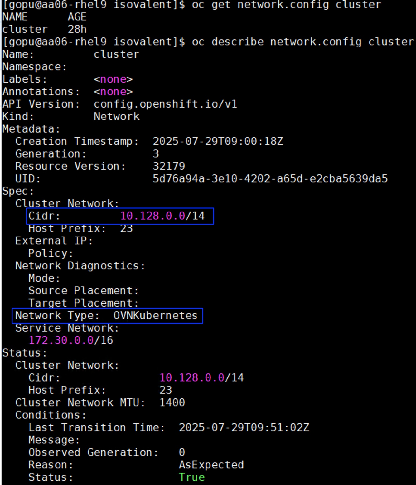
Procedure 3. Update Bare metal Hosts with IPMI user details
This procedure provides the steps to edit the bare metal host configuration with IPMI user details to perform some of the basic maintenance tasks, like restart and poweroff operations.
Step 1. In the Red Hat OpenShift Console, go to Compute > Bare Metal Hosts. For each Bare Metal Host, click the ellipses to the right of the host and select Edit Bare Metal Host. Select Enable power management.
Step 2. From Table 20, fill in the BMC Address and make sure the Boot MAC Address matches the MAC address. For the BMC Username and BMC Password, use what was entered into the Cisco Intersight IPMI over LAN policy. Click Save to save the changes. Repeat this step for all Bare Metal Hosts.
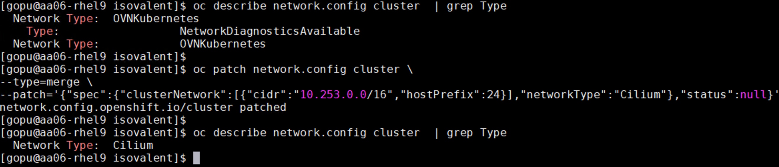
Step 3. Go to Compute > Bare Metal Hosts. When all hosts have been configured, the Status displays “Externally provisioned,” and the Management Address are populated. You can now manage power on the OpenShift hosts from the OpenShift console.
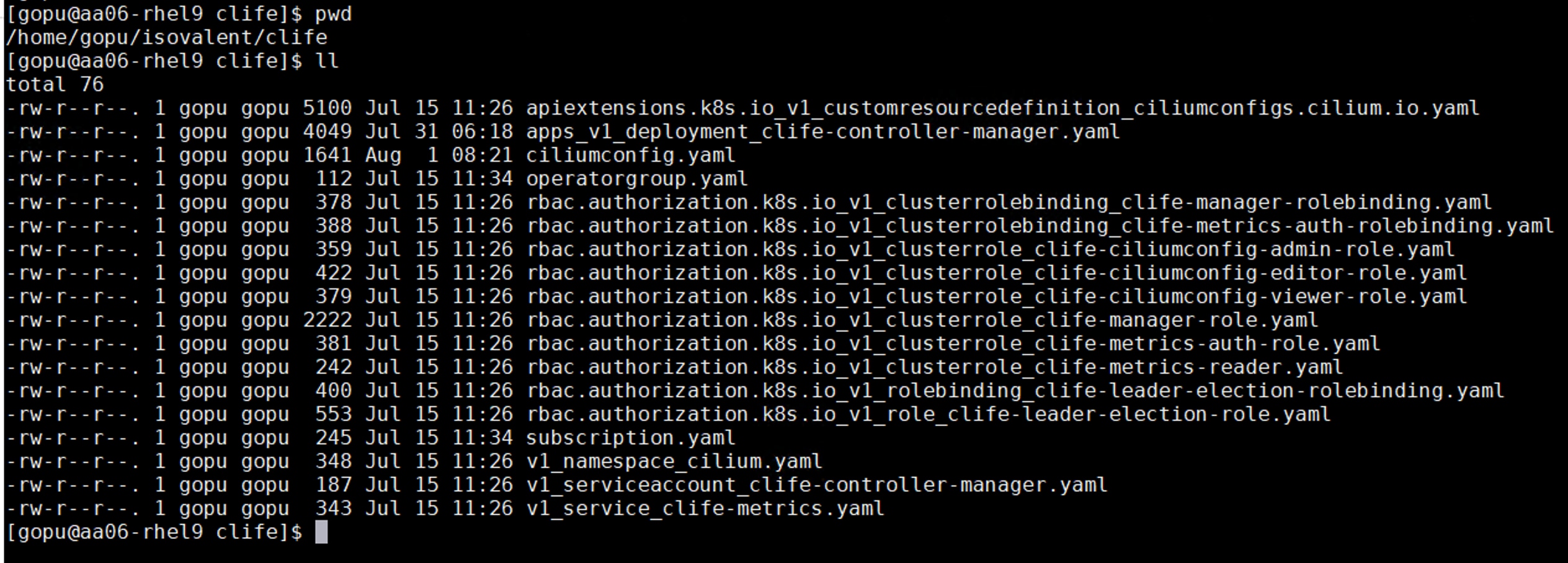
Note: For an IPMI connection to the server, use the BMC IP address. However, for Redfish to connect to the server, use this format for the BMS address; redfish://<BMC IP>/redfish/v1/Systems/<server Serial Number> and make sure to check Disable Certificate Verification. For Instance, for amdn1.fs-ocp.flashstack.local Bare Metal node, the redfish BMC management Address will be: redfish://10.106.0.43/redfish/v1/Systems/WZP28179J0W. When using Redfish to connect to the server, it is critical to check the box for Disable Certificate Verification.
Note: It is recommended to reserve enough resources (CPU and memory) for system components like kubelet. OpenShift Container Platform can automatically determine the optimal system-reserved CPU and memory resources for nodes associated with a specific machine config pool and update the nodes with those values when the nodes start.
Step 4. To automatically determine and allocate the system-reserved resources on nodes, create a KubeletConfig CUSTOM RESOURCE (CR) to set the autoSizingReserved: true parameter as shown below and apply the machine configuration files:
cat dynamic-resource-alloc-workers.yaml
apiVersion: machineconfiguration.openshift.io/v1
kind: KubeletConfig
metadata:
name: dynamic-node-worker
spec:
autoSizingReserved: true
machineConfigPoolSelector:
matchLabels:
pools.operator.machineconfiguration.openshift.io/worker: ""
cat dynamic-resource-alloc-master.yaml
apiVersion: machineconfiguration.openshift.io/v1
kind: KubeletConfig
metadata:
name: dynamic-resource-allow-master
spec:
autoSizingReserved: true
machineConfigPoolSelector:
matchLabels:
pools.operator.machineconfiguration.openshift.io/master: ""
oc apply -f dynamic-resource-alloc-workers.yaml
oc apply -f dynamic-resource-alloc-master.yaml
Note: To manually configure the resources for the system components on the nodes, go to: https://docs.openshift.com/container-platform/4.16/nodes/nodes/nodes-nodes-resources-configuring.html#nodes-nodes-resources-configuring-setting_nodes-nodes-resources-configuring
Procedure 4. Install NMState Operator and configure Host Network Interfaces
As previously explained, NMState operator is used to configure the storage networking interfaces and other Linux bridges on the interfaces. Use the following steps to configure storage network interfaces for iSCSI and NVMe-TCP protocols.
Step 1. In the Red Hat OpenShift Console, go to Operators > OperatorHub. Search for NMState and install Kubernetes NMState Operator.
Step 2. Click Install. Leave all the defaults in place and click Install again. The operator will take a few minutes to install. Once the operator is installed, click View Operator.
Step 3. Select the NMState tab. On the right, click Create NMState. Leave all defaults in place and click Create. The nmstate will be created. You will also need to refresh the console because additional items will be added under Networking.
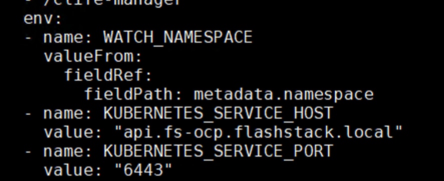
Step 4. Create the following yaml scripts in a folder:
## The following script configures eno6 interfaces for storage traffic over Fabric-A using iSCSI/NVMe-TCP protocols.
cat iscsi-nvme-tcp-a.yaml
apiVersion: nmstate.io/v1
kind: NodeNetworkConfigurationPolicy
metadata:
name: iscsi-nvme-tcp-a-nncp
spec:
#nodeSelector:
#node-role.kubernetes.io/worker: ''
desiredState:
interfaces:
- name: eno6
description: ipv4 Configuring on eno6 for iscsi storage traffic via Fabric A
type: ethernet
state: up
mtu: 9000
ipv4:
dhcp: true
enabled: true
ipv6:
enabled: false
## The following script configures eno7 interfaces for storage traffic over Fabric-B using iSCSI/NVMe-TCP protocols.
cat iscsi-nvme-tcp-b.yaml
apiVersion: nmstate.io/v1
kind: NodeNetworkConfigurationPolicy
metadata:
name: iscsi-nvme-tcp-b-nncp
spec:
#nodeSelector:
#node-role.kubernetes.io/worker: ''
desiredState:
interfaces:
- name: eno7
description: ipv4 Configuring on eno7 for iscsi storage traffic
type: ethernet
state: up
ipv4:
dhcp: true
enabled: true
ipv6:
enabled: false
## The following script configures eno11 interface for accessing S3 complaint Object storage provided by ##FlashBlade for Px-Backup usecase
cat objectstorage-eno11.yaml
apiVersion: nmstate.io/v1
kind: NodeNetworkConfigurationPolicy
metadata:
name: objectstorage-nncp
spec:
#nodeSelector:
#node-role.kubernetes.io/worker: ''
desiredState:
interfaces:
- name: eno11
description: ipv4 Configuring on eno11 for object storage access from FlashBlade
type: ethernet
state: up
mtu: 9000
ipv4:
dhcp: true
enabled: true
ipv6:
enabled: false
## The following script configures eno12 interface used for carrying replication data traffic among the Portworx nodes.
cat px-repln-eno12.yaml
apiVersion: nmstate.io/v1
kind: NodeNetworkConfigurationPolicy
metadata:
name: px-repln-nncp
spec:
#nodeSelector:
#node-role.kubernetes.io/worker: ''
desiredState:
interfaces:
- name: eno12
description: ipv4 Configuring on eno12 for portworx node to node replciatiom traffic
type: ethernet
state: up
mtu: 9000
ipv4:
dhcp: true
enabled: true
ipv6:
enabled: false
## The following script configures eno8 interface as a Linux bridge for VM’s management access using vlans ## 1062 and 1063. In the later sections, required NADs will be created for VMs/PODs to get access to this ##bridge.
cat br-vmmgmt.yaml
apiVersion: nmstate.io/v1
kind: NodeNetworkConfigurationPolicy
metadata:
name: bridge-vmgmt-nncp
spec:
#nodeSelector:
# node-role.kubernetes.io/worker: ""
desiredState:
interfaces:
- name: br-vm-network
description: Linux bridge using eno8
type: linux-bridge
state: up
ipv4:
enabled: false
bridge:
options:
stp:
enabled: false
port:
- name: eno8
##Optional Configruation for VM’s direct storage access using In-Guest iSCSI protocol.
## The following script configures eno9 interface as a Linux bridge for VM’s storage traffic over Fabric-A.
cat iscsi-in-guest-a.yaml
apiVersion: nmstate.io/v1
kind: NodeNetworkConfigurationPolicy
metadata:
name: iscsi-vm-a-nncp
spec:
#nodeSelector:
#node-role.kubernetes.io/worker: ''
desiredState:
interfaces:
- name: iscsi-vm-a
description: Linux bridge for in-guest iscsi-A with eno9 as a port
type: linux-bridge
state: up
ipv4:
enabled: false
ipv6:
enabled: false
bridge:
options:
stp:
enabled: false
port:
- name: eno9
## The following script configures eno10 interface as a Linux bridge for VM’s storage over Fabric-B.
cat iscsi-in-guest-b.yaml
apiVersion: nmstate.io/v1
kind: NodeNetworkConfigurationPolicy
metadata:
name: iscsi-vm-b-nncp
spec:
#nodeSelector:
#node-role.kubernetes.io/worker: ''
desiredState:
interfaces:
- name: iscsi-vm-b
description: Linux bridge for in-guest iscsi-B with eno10 as a port
type: linux-bridge
state: up
ipv4:
enabled: false
ipv6:
enabled: false
bridge:
options:
stp:
enabled: false
port:
- name: eno10
Note: If using combined control plane and worker nodes (mixed OpenShift deployment), separate MachineConfig files for workers and masters (control-plane) need to be created and applied.
Step 5. Apply the files and verify that all interfaces are configured accordingly:
oc apply -f iscsi-nvme-tcp-a.yaml
Oc apply -f iscsi-nvme-tcp-b.yaml
oc apply -f objectstorage-eno11.yaml
oc apply -f px-repln-eno12.yaml
oc apply -f br-vmmgmt.yaml
oc apply -f iscsi-in-guest-a.yaml
oc apply -f iscsi-in-guest-b.yaml
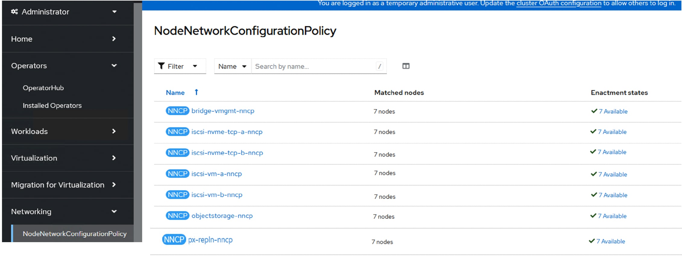
In the following sections, the required NADs will be created for VMs/PODs to get access to these bridges.
Procedure 5. Add an Additional Administrator User
It is recommended to install a permanent administrative user to an OpenShift cluster to provide an alternative to logging in with the “temporary” kubeadmin user.
For this validation, an HTPasswd user is created with admin rights on the OpenShift cluster by following the instructions detailed here: https://access.redhat.com/solutions/4039941.
Step 1. After creating an admin user using the HTPasswd method, logout from the current session and login again by selecting the htpasswd option as shown below:
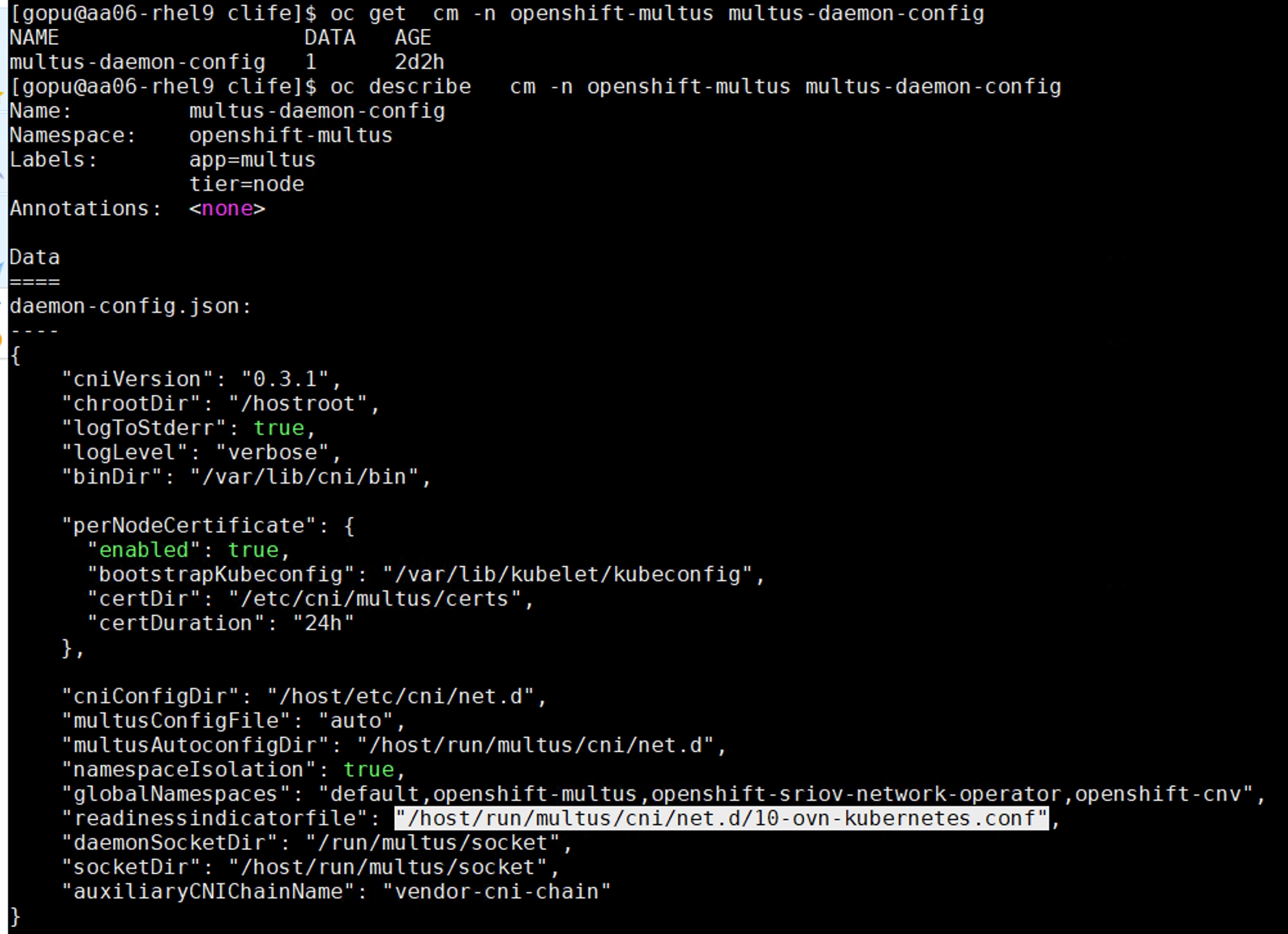
Install NVIDIA GPU Operator and Drivers
This chapter contains the following:
This chapter provides the procedures to install the required NVIDIA GPU operators, CUDA drivers and so on, to work with NVIDIA GPUs.
This section provides the procedures to install the NVIDIA GPU operators.
Procedure 1. Install NVIDIA GPU Operators
If you have GPUs installed in your Cisco UCS servers, you need to install the Node Feature Discovery (NFD) Operator to detect NVIDIA GPUs and the NVIDIA GPU Operator to make these GPUs available to containers and virtual machines.
Step 1. In the OpenShift Container Platform web console, click Operators > OperatorHub.
Step 2. Type Node Feature in the filter box and then click the Node Feature Discovery Operator with Red Hat in the upper right corner. Click Install.
Step 3. Do not change any settings and click Install.
Step 4. When the Install operator is ready for use, click View Operator.
Step 5. In the bar to the right of Details, click NodeFeatureDiscovery.
Step 6. Click Create NodeFeatureDiscovery.
Step 7. Click Create.
Step 8. When the nfd-instance has a status of Available, Upgradeable, click Compute > Nodes.
Step 9. Select a node that has one or more GPUs and then click Details.
The label feature.node.kubernetes.io/pci-10de.present=true should be present on the host.
This label appears on all nodes with GPUs:
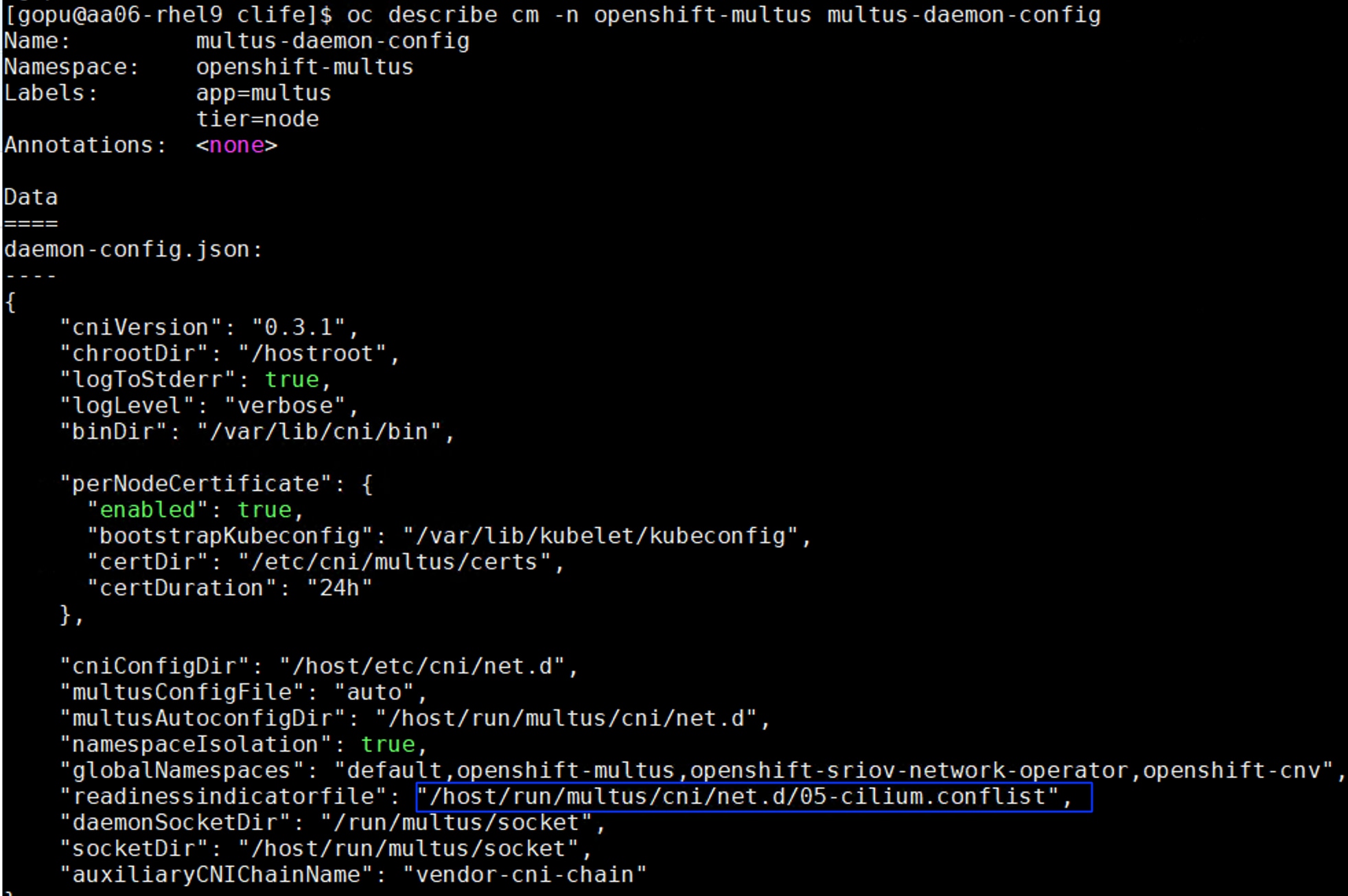
Step 10. Go to Operators > OperatorHub.
Step 11. Type NVIDIA in the filter box and then click the NVIDIA GPU Operator. Click Install.
Step 12. Do not change any settings and click Install.
Step 13. When the Install operator is ready for use, click View Operator.
Step 14. In the bar to the right of Details, click ClusterPolicy.
Step 15. Click Create ClusterPolicy.
Step 16. Do not change any settings and scroll down and click Create. This will install the latest GPU driver.
Step 17. Wait for the gpu-cluster-policy Status to become Ready.
Step 18. Connect to a terminal window on the OpenShift Installer machine. Type the following commands. The output shown is for two servers that are equipped with GPUs:
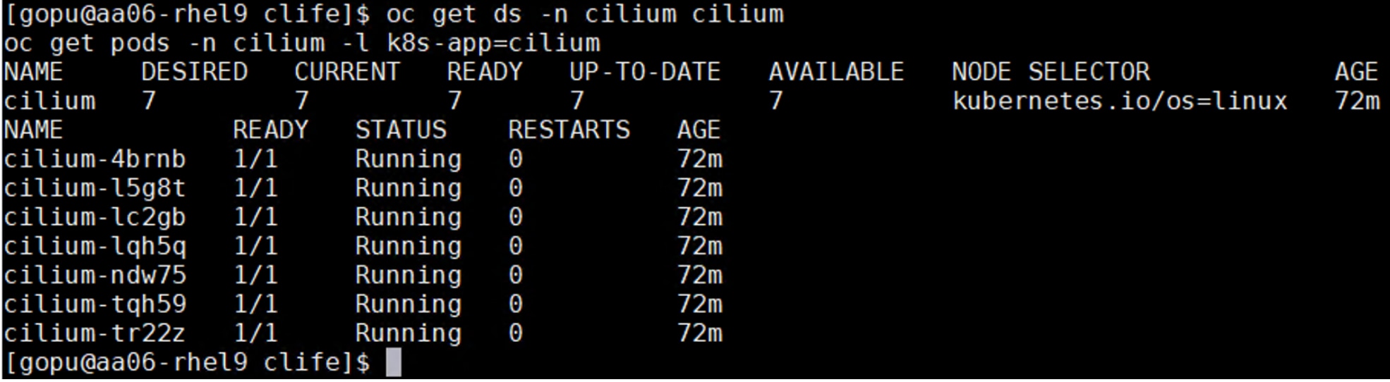
oc project nvidia-gpu-operator
[gopu@aa06-rhel9 ~]$ oc project nvidia-gpu-operator
Now using project "nvidia-gpu-operator" on server "https://api.fs-ocp.flashstack.local:6443".
[gopu@aa06-rhel9 ~]$
[gopu@aa06-rhel9 ~]$ oc get pods
NAME READY STATUS RESTARTS AGE
gpu-feature-discovery-br6km 1/1 Running 0 10m
gpu-feature-discovery-tgdcp 1/1 Running 0 10m
gpu-operator-c596d8bc-wqxwx 1/1 Running 0 12m
nvidia-container-toolkit-daemonset-d798z 1/1 Running 0 10m
nvidia-container-toolkit-daemonset-f6w2p 1/1 Running 0 10m
nvidia-cuda-validator-pxgr4 0/1 Completed 0 8m9s
nvidia-cuda-validator-zkdt7 0/1 Completed 0 8m9s
nvidia-dcgm-exporter-2888x 1/1 Running 0 10m
nvidia-dcgm-exporter-pswvs 1/1 Running 0 10m
nvidia-dcgm-rt46d 1/1 Running 0 10m
nvidia-dcgm-sgl95 1/1 Running 0 10m
nvidia-device-plugin-daemonset-hb6hq 1/1 Running 0 10m
nvidia-device-plugin-daemonset-m5mmc 1/1 Running 0 10m
nvidia-driver-daemonset-418.94.202507091512-0-l25ws 2/2 Running 2 11m
nvidia-driver-daemonset-418.94.202507091512-0-pnwqt 2/2 Running 2 11m
nvidia-mig-manager-8fp96 1/1 Running 0 10m
nvidia-node-status-exporter-97jmp 1/1 Running 0 10m
nvidia-node-status-exporter-jv4j5 1/1 Running 0 10m
nvidia-operator-validator-cc6dm 1/1 Running 0 10m
nvidia-operator-validator-vxv26 1/1 Running 0 10m
[gopu@aa06-rhel9 ~]$
Step 19. Connect to one of the nvidia-driver-daemonset containers and view the GPU status:
oc exec -it nvidia-driver-daemonset-418.94.202507091512-0-pnwqt -n nvidia-gpu-operator -- nvidia-smi
Sun Sep 21 11:36:37 2025
+-----------------------------------------------------------------------------------------+
| NVIDIA-SMI 580.82.07 Driver Version: 580.82.07 CUDA Version: 13.0 |
+-----------------------------------------+------------------------+----------------------+
| GPU Name Persistence-M | Bus-Id Disp.A | Volatile Uncorr. ECC |
| Fan Temp Perf Pwr:Usage/Cap | Memory-Usage | GPU-Util Compute M. |
| | | MIG M. |
|=========================================+========================+======================|
| 0 NVIDIA H100 NVL On | 00000000:01:00.0 Off | 0 |
| N/A 32C P0 56W / 400W | 0MiB / 95830MiB | 0% Default |
| | | Disabled |
+-----------------------------------------+------------------------+----------------------+
| 1 NVIDIA H100 NVL On | 00000000:E1:00.0 Off | 0 |
| N/A 35C P0 58W / 400W | 0MiB / 95830MiB | 0% Default |
| | | Disabled |
+-----------------------------------------+------------------------+----------------------+
+-----------------------------------------------------------------------------------------+
| Processes: |
| GPU GI CI PID Type Process name GPU Memory |
| ID ID Usage |
|=========================================================================================|
| No running processes found |
+-----------------------------------------------------------------------------------------+
Procedure 2. Enable the GPU Monitoring Dashboard
Step 1. Go to https://docs.nvidia.com/datacenter/cloud-native/openshift/latest/enable-gpu-monitoring-dashboard.html, enable the GPU Monitoring Dashboard to monitor GPUs in the OpenShift Web-Console.
Migrate OpenShift OVN to Isovalent Networking for Kubernetes
This chapter contains the following:
● Migrate OpenShift Cluster from OpenShift OVN to Isovalent Networking for Kubernetes
Migrate OpenShift Cluster from OpenShift OVN to Isovalent Networking for Kubernetes
The OVN-Kubernetes network plugin is the default network provider for OpenShift. As previously stated, this FlashStack deployment uses Isovalent Enterprise as CNI plugin for providing OpenShift networking.
This section provides the steps to migrate to Isovalent Networking for Kubernetes in an existing OpenShift cluster.
Note: Isovalent Networking for Kubernetes is a fully certified and supported network plugin for Red Hat OpenShift Container Platform. Migration does incur some downtime, as nodes and pods are restarted. Hence it is recommended to contact the Isovalent support team before proceeding with migrating on an active existing OpenShift cluster.
Note: Before proceeding with the migration, ensure that OpenShift cluster is full functional with OVN-Kubernetes, meaning all nodes are online and cluster operators are not running in a degraded state.
Note: With green filed environments, migration from OVN to Isovalent Enterprise must be performed before installing any other application or infrastructure pods (for instance storage). In case of brown filed environments, this activity must be performed in the maintenance windows only.
Note: Hubble Timescape is another alternative for Hubble for that provides insights into live and historical data. Hubble is lightweight version and more suitable for compact design providing same level of insights into the network traffic but without historical data. For future releases of Isovalent, it is recommended to use HubbleTimescape instead of Hubble.
Procedure 1. Disable the Cluster Network Operator
The Cluster Network Operator (CNO) deploys and manages cluster network components in OpenShift, including OVN-Kubernetes. The first step in a migration is to temporarily disable this operator to prevent overwriting changes you make to the cluster network configuration. The following screenshot shows the components of OpenShift-network-operator namespace:
![[ gopu@aa06- rhel9 isovalent]$ oc get all -n openshift-network-operatorWarning: apps . openshift. io/v1 DeploymentConfig is deprecated in v4.14+, unavailable in v4. 10000+NAMEREADYSTATUSRESTARTSAGEpod/iptables-alerter-4wfgb1/1Running027hpod/iptables-alerter-hlnv61/1Running027hpod/iptables -alerter-hwzrk1/1Running27hpod/iptables -alerter- kx59h1/1Running27hpod/iptables -alerter-qhld81/1Running127hpod/iptables-alerter-r9w6q1/1Running27hpod/iptables -alerter-t9pkf1/1Running027hpod/network-operator-c4496d898-wn5671/1Running3 (27h ago)27hNAMETYPECLUSTER - IPEXTERNAL - IPPORT ( S)AGEservice/metricsClusterIPNone<none>9104/TCP28hNAMEDESIREDCURRENTREADYUP - TO-DATEAVAILABLENODE SELECTORAGEdaemonset . apps/iptables - alerter77777kubernetes . io/os=linux27hNAMEREADYUP - TO-DATEAVAILABLEAGEdeployment . apps/network-operator1/11128hNAMEDESIREDCURRENTREADYAGEreplicaset . apps/network-operator-c4496d89811128h[ gopu@aa06 - rhel9 isovalent ]$](/c/dam/en/us/td/docs/unified_computing/ucs/UCS_CVDs/flashstack_ocp_baremetal_ucs_amd_imm.docx/_jcr_content/renditions/flashstack_ocp_baremetal_ucs_amd_imm_77.png)
Step 1. Log into Installer VM, create a folder and then create .yaml file as shown below. Patch the cluster with this file.
[gopu@aa06-rhel9 isovalent]$ mkdir isovalent
[gopu@aa06-rhel9 isovalent]$ cd isovalent
[gopu@aa06-rhel9 isovalent]$ cat cno-disable.yaml
- op: add
path: /spec/overrides
value:
- kind: Deployment
group: apps
name: network-operator
namespace: openshift-network-operator
unmanaged: true
oc patch clusterversion version –-type json -–patch-file cno-disable.yaml
Step 2. Scale down the network operator from 1 to 0:
oc scale deployment -n openshift-network-operator network-operator --replicas=0
oc get pods -n openshift-network-operator
![[ gopu@aa06- rhel9 isovalent ]$ oc get pods -n openshift-network-operatorNAMEREADYSTATUSRESTARTSAGEiptables-alerter-4wfgb1/1Running027hiptables-alerter-hlnv61/1Running027hiptables-alerter-hwzrk1/1Running027hiptables -alerter-kx59h1/1Running27hiptables-alerter-qhld81/1Running127hiptables-alerter-r9w6q1/1Running027hiptables-alerter-t9pkf1/1Running27h[ gopu@aa06- rhel9 isovalent ] $](/c/dam/en/us/td/docs/unified_computing/ucs/UCS_CVDs/flashstack_ocp_baremetal_ucs_amd_imm.docx/_jcr_content/renditions/flashstack_ocp_baremetal_ucs_amd_imm_78.png)
Step 3. Delete the applied-cluster configmap in the openshift-network-operator namespace. This removes the state file created when the cluster was initially deployed.
oc delete configmap applied-cluster -n openshift-network-operator
Procedure 2. Change Network plugin to Cilium
When changes are made to network objects, the Machine Config Operator will automatically reboot nodes to make them compliant with the new configuration. To prevent this until the nodes are rebooted later in this process, you must put a "pause" on management.
Step 1. Apply the pause to the automatic node reboots:
oc patch --type=merge --patch='{"spec":{"paused":true}}' mcp/master
oc patch --type=merge --patch='{"spec":{"paused":true}}' mcp/worker

Step 2. Configure the Cluster Network Operator to use Isovalent Enterprise. Review the network.config object specifications before making changes.

Step 3. Patch the network.config object with network CIDR you want to use for Cilium. This example uses 10.253.0.0/16 as CIDR for Cilium pod network.
Note: The network CIDR you choose must not overlap with the existing OVN-Kubernetes network.
oc patch network.config cluster --type=merge \
--patch='{"spec":{"clusterNetwork":[{"cidr":"10.253.0.0/16","hostPrefix":24}],"networkType":"Cilium"},"status":null}'
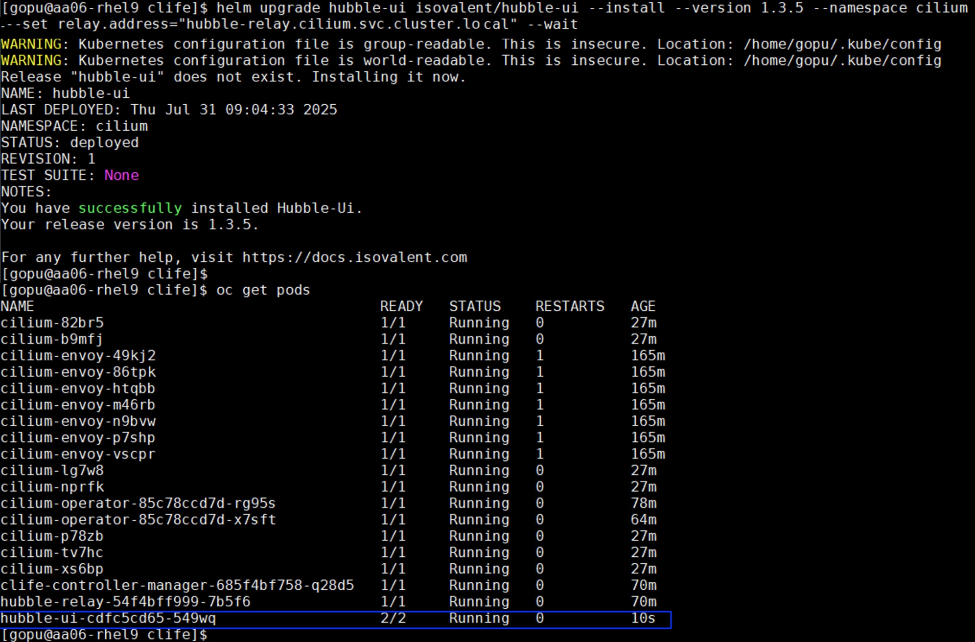
Step 4. Patch the network.cluster object to set the default network for the cluster to Cilium, keep kube-proxy from being deployed, and use the CIDR you've chosen. Isovalent Networking for Kubernetes will replace kube-proxy functionality:
oc patch network.operator cluster --type=merge \
--patch='{"spec":{"clusterNetwork":[{"cidr":"10.253.0.0/16","hostPrefix":24}],"defaultNetwork":{"type":"Cilium"},"deployKubeProxy":false},"status":null}'
Procedure 3. Configure Isovalent Networking Kubernetes Manifests
Step 1. Download the Isovalent Networking for Kubernetes manifests from the Install Networking for Kubernetes on Red Hat OpenShift guide and extract them locally.
mkdir clife
tar -xzvf /path/to/clife-v1.x.y.tar.gz -C clife
cd clife
The following image shows the files that make up the entire Cilium CNI and are important to configure for any customization:
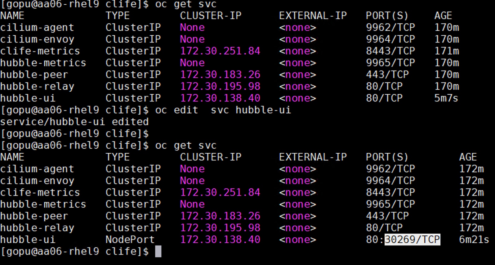
Step 2. Customize the Isovalent deployment according to our environment and requirements by updating ciliumconfig.yaml file.
The following screenshot highlights the changes in bold made to the ciliumconfig.yaml:
cat ciliumconfig.yaml
apiVersion: cilium.io/v1alpha1
kind: CiliumConfig
metadata:
name: cilium-enterprise
namespace: cilium
spec:
socketLB:
hostNamespaceOnly: true
securityContext:
privileged: true
ipam:
mode: "cluster-pool"
operator:
clusterPoolIPv4PodCIDRList: ["10.253.0.0/16"]
clusterPoolIPv4MaskSize: 24
cni:
binPath: "/var/lib/cni/bin"
confPath: "/var/run/multus/cni/net.d"
exclusive: false
prometheus:
enabled: true
serviceMonitor: {enabled: true}
kubeProxyReplacement: "true"
k8sServiceHost: "api.fs-ocp.flashstack.local"
k8sServicePort: 6443
hubble:
tls:
enabled: true
relay:
enabled: true
serviceMonitor: {enabled: true}
enabled: true
metrics:
enabled:
- dns:labelsContext=source_namespace,destination_namespace
- drop:labelsContext=source_namespace,destination_namespace
- tcp:labelsContext=source_namespace,destination_namespace
- icmp:labelsContext=source_namespace,destination_namespace
- flow:labelsContext=source_namespace,destination_namespace;sourceContext=workload-name|reserved-identity;destinationContext=workload-name|reserved-identity
- "httpV2:exemplars=true;labelsContext=source_ip,source_namespace,source_workload,destination_ip,destination_namespace,destination_workload,traffic_direction;sourceContext=workload-name|reserved-identity;destinationContext=workload-name|reserved-identity"
- flow_export
operator:
prometheus: {enabled: true}
serviceMonitor: {enabled: true}
devices: "br-ex,eno5"
tunnelPort: 4789
Some layered products like OpenShift Service Mesh, OpenShift Virtualization and OpenShift sandboxed containers may not work well with socket level load balancing. Cilium supports bypassing the socket level load balancers by setting spec.socketLB.hostNamespaceOnly: true.
We need to explicitly mention the openvswitch devices under spec.devices: “br-ex,eno5”. Here, br-ex is the openvswitch used by OVN-K and eno5 is the default network device used by Cilium. Replace k8sServiceHost and k8sServicePort with the internal API server hostname and API port for your environment.
Hubble is part of Cilium platform, and it is a fully distributed networking and security observability platform for cloud native workloads. It is built on top of Cilium and eBPF to enable deep visibility into the communication and behavior of services as well as the networking infrastructure in a completely transparent manner. Relay is an extra component that aggregates observability data across multiple Hubble server instances across all nodes (or even clusters) in your setup. Enable both Hubble and Relay by editing the spec.hubble section as previously stated.
Step 3. Add your OpenShift server details to the apps_v1_deployment_clife-controller-manager.yaml file under the env section as shown below:
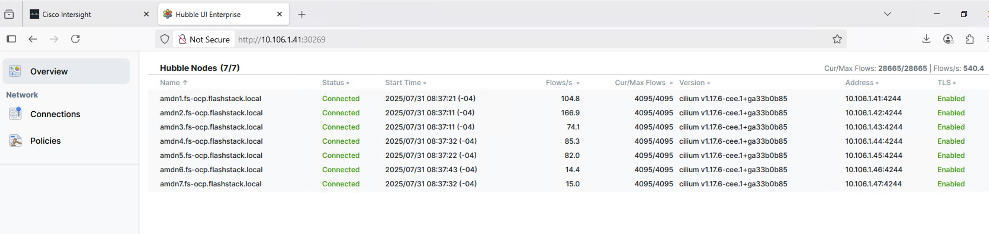
Step 4. Apply all files under clife folder:
until oc apply -f .
do
sleep 1
done
Step 5. Wait until all the corresponding pods comes up neatly in Cilium namespace.
![[ gopu@aa06- rhe19 clife]$ oc get podsNAMEREADYSTATUSRESTARTSAGEcilium-4brnb1/1Running04m6scilium-envoy - 49kj 21/1Running4m6scilium-envoy-86tpk1/1Running04m6scilium-envoy-htqbb1/1Running4m6scilium-envoy-m46rb1/1Running04m6scilium-envoy-n9bvw1/1Running04m6scilium-envoy-p7shp1/1Running04m6scilium-envoy - vscpr1/1Running04m6scilium-15g8t1/1Running04m6scilium-lc2gb1/1Running4m6scilium- 1qh5q1/1Running4m6scilium-ndw751/1Running4m6scilium-operator-85c78ccd7d-nc49r1/1Running04m6scilium-operator-85c78ccd7d-nlg5s1/1Running04m6scilium-tqh591/1Running04m6scilium-tr22z1/1Running04m6sclife-controller-manager-685f4bf758-24pvk1/1Running4m13shubble- relay -54f4bff999-xjnx41/1Running04m6s[ gopu@aa06 - rhel9 clife]$](/c/dam/en/us/td/docs/unified_computing/ucs/UCS_CVDs/flashstack_ocp_baremetal_ucs_amd_imm.docx/_jcr_content/renditions/flashstack_ocp_baremetal_ucs_amd_imm_84.png)
Step 6. The OpenShift Multus configuration will need to be changed to point to Cilium instead of OVN-Kubernetes. The following screenshot shows Multus pointing to OVN configuration file:
![[ gopu@aa06- rhel9 clife]$ oc get cm -n openshift-multus multus -daemon-configNAMEDATAAGEmul tus - daemon - config12d2h[ gopu@aa06- rhel9 clife]$ oc describecm -n openshift-multus multus -daemon-configName :mul tus - daemon - configNamespace :openshift -multusLabels :app=multustier=nodeAnnotations :<none>Datadaemon - config . json :{"cniVersion": "0.3.1","chrootDir": "/hostroot","logToStderr": true,"logLevel": "verbose","binDir": "/var/lib/cni/bin","perNodeCertificate": {"enabled": true,"bootstrapKubeconfig" : "/var/lib/kubelet/kubeconfig","certDir": "/etc/cni/multus/certs","certDuration": "24h"},"cniConfigDir": "/host/etc/cni/net.d","multusConfigFile": "auto""multusAutoconfigDir" : "/host/run/multus/cni/net. d","namespaceIsolation": true,"globalNamespaces" : "default, openshift -multus , openshift -sriov-network-operator, openshift-cnv","readinessindicatorfile": "/host/run/multus/cni/net. d/10-ovn-kubernetes. conf","daemonSocketDir" : "/run/multus/socket""socketDir" : "/host/run/multus/socket","auxiliaryCNIChainName" : "vendor-cni-chain"](/c/dam/en/us/td/docs/unified_computing/ucs/UCS_CVDs/flashstack_ocp_baremetal_ucs_amd_imm.docx/_jcr_content/renditions/flashstack_ocp_baremetal_ucs_amd_imm_85.png)
Step 7. Run the following command to replace the string /host/run/Multus/cni/net.d/10-ovn-kubernetes.conf with host/run/multus/cni/net.d/05-cilium.conflist. When the string is replaced, restart multus operator:
KUBE_EDITOR="sed -i s;host/run/multus/cni/net.d/10-ovn-kubernetes.conf;host/run/multus/cni/net.d/05-cilium.conflist;" oc edit cm -n openshift-multus multus-daemon-config
oc rollout restart -n openshift-multus ds/multus
The following screenshot shows the multus configuration after replacing the OVN config file with the Cilium config file:

Step 8. Wait for Isovalent Networking for Kubernetes to fully deploy in the cilium namespace before proceeding. Run the following command and ensure all the Cilium pods in cilium namespace are in running state:

Procedure 4. Enable OpenShift Operator Management
Step 1. Restart the OpenShift API server and Machine Config Operator pods. Wait for few minutes and confirm that all API server pods are up and running:
oc delete pod -n openshift-kube-apiserver -l apiserver=true
oc -n openshift-machine-config-operator rollout restart deploy/machine-config-controller
oc -n openshift-machine-config-operator rollout restart deploy/machine-config-operator
oc get pods -n openshift-kube-apiserver -l apiserver=true
Step 2. Scale the Cluster Network Operator to start managing the network with Cilium as the default network plugin:
oc scale deployment -n openshift-network-operator network-operator --replicas=1
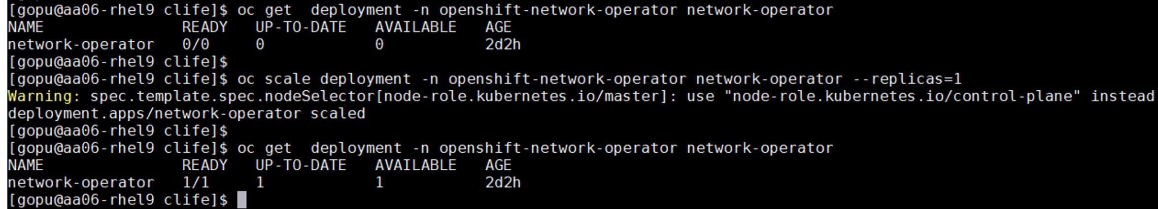
Step 3. Configure the Cluster Version Operator to manage the Network Operator once again:
oc patch clusterversions version --type=merge --patch '{"spec":{"overrides":null}}'
Step 4. Reboot the nodes by removing the pauses on the Machine Config Operator:
oc patch --type=merge --patch='{"spec":{"paused":false}}' mcp/master
oc patch --type=merge --patch='{"spec":{"paused":false}}' mcp/worker
This step will immediately begin rebooting nodes in a safe fashion, by cordoning and draining workloads before a reboot. The cluster will be in a degraded state until all nodes are back online. The impact can be reduced by using multiple machine pools for workloads and removing the pause in sequence.
Step 5. During node reboot, it is possible that some pods cannot be evicted. Run the following command to check the following logs for further information:
oc logs -n openshift-machine-config-operator -l k8s-app=machine-config-controller -f
Procedure 5. Verify the Migration and Test Network connectivity with Cilium
Step 1. Once all nodes have been rebooted, check that all nodes are reporting as "Ready" and that all pods are running as expected:
oc get nodes
oc get pods --all-namespaces -o wide --sort-by='{.spec.nodeName}'
oc get clusteroperators
Step 2. Make sure all Cluster Operators are working as expected:
![[ gopu@aa06- rhe19 clife]$ oc get clusteroperators . config. openshift. ioNAMEVERSIONAVAILABLEPROGRESSINGDEGRADEDSINCEauthentication4.18.20TrueFalseFalse19mbaremetal4.18.20TrueFalseFalse2d3hcloud-controller-manager4.18.20TrueFalseFalse2d3hcloud-credential4.18.20TrueFalseFalse2d3hcluster-autoscaler4.18.20TrueFalseFalse2d3hconfig-operator4.18.20TrueFalseFalse2d3hconsole4.18.20TrueFalseFalse23mcontrol-plane-machine-set4.18.20TrueFalseFalse2d3hcsi-snapshot - controller4.18.20TrueFalseFalse2d3hdns4.18.20TrueFalseFalse2d2hetcd4.18.20TrueFalseFalse42mimage- registry4.18.20TrueFalseFalse2d2hingress4.18.20TrueFalseFalse2d2hinsights4.18.20TrueFalseFalse2d3hkube-apiserver4.18.20TrueFalseFalse2d2hkube-controller-manager4.18.20TrueFalseFalse2d2hkube-scheduler4.18.20TrueFalseFalse2d2hkube-storage- version -migrator4.18.20TrueFalseFalse35mmachine-api4.18.20TrueFalseFalse2d2hmachine-approver4.18.20TrueFalseFalse2d3hmachine-config4.18.20TrueFalseFalse2d3hmarketplace4.18.20TrueFalseFalse2d3hmonitoring4.18.20TrueFalseFalse2d2hnetwork4.18.20TrueFalseFalse2d3hnode- tuning4.18.20TrueFalseFalse2d2holm4.18.20TrueFalseFalse35mopenshift -apiserver4.18.20TrueFalseFalse27mopenshift-controller-manager4.18.20TrueFalseFalse2d2hopenshift-samples4.18.20TrueFalseFalse2d2hoperator-lifecycle-manager4.18.20TrueFalseFalse2d3hoperator-lifecycle-manager-catalog4.18.20TrueFalseFalse2d3hoperator-lifecycle-manager-packageserver4.18.20TrueFalseFalse35mservice-ca4.18.20TrueFalseFalse2d3hstorage4.18.20TrueFalseFalse2d3h[ gopu@aa06 - rhel9 clife]$](/c/dam/en/us/td/docs/unified_computing/ucs/UCS_CVDs/flashstack_ocp_baremetal_ucs_amd_imm.docx/_jcr_content/renditions/flashstack_ocp_baremetal_ucs_amd_imm_89.png)
Step 3. If you set devices in ciliumconfig.yaml file, you can now delete them. Cilium should be able to auto-detect non-openvswitch network devices:
sed -i "s/br-ex,ens5//" path/to/clife/ciliumconfig.yaml
oc apply -f path/to/clife
oc -n cilium rollout restart ds/cilium
Step 4. Verify that Cilium restarted and is healthy:
oc get ds -n cilium cilium
oc get pods -n cilium -l k8s-app=cilium
Step 5. When everything is healthy, remove the openshift-ovn-kubernetes namespace:
oc delete namespace openshift-ovn-kubernetes
![[ gopu@aa06- rhel9 clife]$ oc delete namespace openshift -ovn-kubernetesnamespace "openshift -ovn- kubernetes" deleted[ gopu@aa06 - rhe19 clife]$](/c/dam/en/us/td/docs/unified_computing/ucs/UCS_CVDs/flashstack_ocp_baremetal_ucs_amd_imm.docx/_jcr_content/renditions/flashstack_ocp_baremetal_ucs_amd_imm_90.png)
Procedure 6. Test network connectivity with Cilium
An OpenShift Security Constraint (SCC) will be created to allow the required connectivity tests in Cilium-test namespace.
Step 1. Run the following scripts to create OpenShift SSC and to deploy the Cilium network connectivity testing pods:
cat cilium-scc.yaml
apiVersion: security.openshift.io/v1
kind: SecurityContextConstraints
metadata:
name: cilium-test
allowHostPorts: true
allowHostNetwork: true
users:
- system:serviceaccount:cilium-test:default
priority: null
readOnlyRootFilesystem: false
runAsUser:
type: MustRunAsRange
seLinuxContext:
type: MustRunAs
volumes: null
allowHostDirVolumePlugin: false
allowHostIPC: false
allowHostPID: false
allowPrivilegeEscalation: false
allowPrivilegedContainer: false
allowedCapabilities: null
defaultAddCapabilities: null
requiredDropCapabilities: null
groups: null
oc create ns cilium-test
oc project cilium-test
oc apply -f cilium-scc.yaml -n cilium-test
## apply the following script that creates a set of pods for various network connectivity tests.
oc apply -n cilium-test -f https://raw.githubusercontent.com/cilium/cilium/1.14.3/examples/kubernetes/connectivity-check/connectivity-check.yaml
This will configure a series of deployments that will use various connectivity paths to connect to each other. Connectivity paths include with and without service load-balancing and various network policy combinations. The pod name indicates the connectivity variant, and the readiness and liveness gate indicates success or failure of the test:
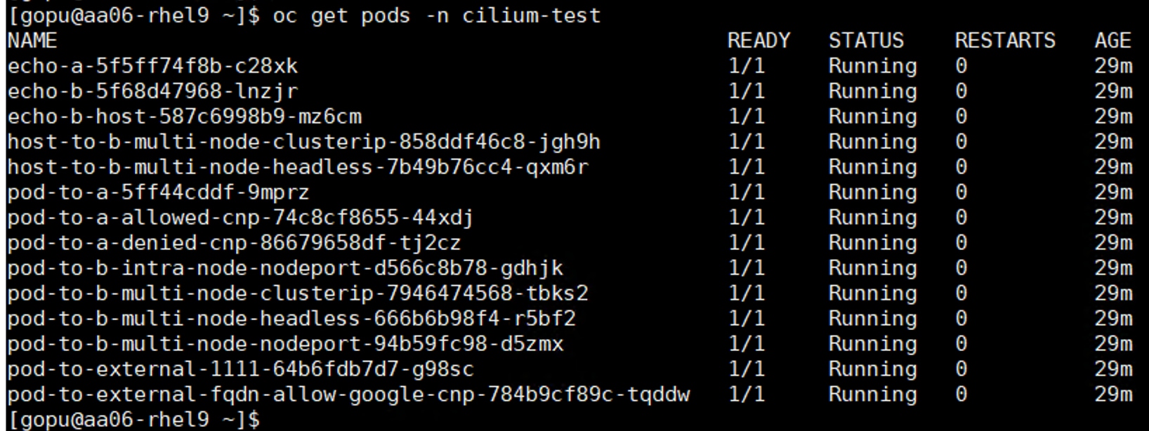
To access the Hubble-Relay services, Hubble client tools like Hubble CLI and UI needs to be installed. This section covers the deploying Hubble UI and CLI on top of Isovalent in OpenShift Cluster.
Procedure 1. Install Hubble UI
Step 1. Verify Isovalent helm repo is added. If not, add it by running the following commands. If the repo is already added, upgrade it:
helm repo list
helm repo add isovalent https://helm.isovalent.com
helm repo update
Step 2. Search for the latest version of hubble UI image available. For relay-address, set service name of hubble-relay as shown below. Wait for few minutes and check the hubble UI pod.
helm search repo -l isovalent
oc get svc oc get svc -n cilium | grep relay
hubble-relay ClusterIP 172.30.195.98 <none> 80/TCP 51d
helm upgrade hubble-ui isovalent/hubble-ui --install --version 1.3.5 --namespace cilium --set relay.address="hubble-relay.cilium.svc.cluster.local" –wait
oc get pods -n cilium

Step 3. Set the hubble-ui service type by setting .spec.type from ClusterIP to NodePort to as shown below. Note down the nodeport number and access the hubble-ui service by using this URL https://nodeip:nodeport.
![[ gopu@aa06- rhel9 clife]$ oc get svcNAMETYPECLUSTER - IPEXTERNAL - IPPORT (S)AGEcilium-agentClusterIPNone<none>9962/TCP170mcilium-envoyClusterIPNone<none>9964/TCP170mclife-metricsClusterIP172.30.251.84<none>8443/TCP171mhubble-metricsClusterIPNone<none>9965/TCP170mhubble-peerClusterIP172.30.183.26<none>443/TCP170mhubble-relayClusterIP172.30.195.98<none>80/TCP170mhubble-uiClusterIP172.30.138.40<none>80/TCP5m7s[ gopu@aa06- rhel9 clife]$ oc editsvc hubble-uiservice/hubble-ui edited[ gopu@aa06- rhel9 clife]$[ gopu@aa06- rhel9 clife]$ oc get svcNAMETYPECLUSTER - IPEXTERNAL - IPPORT (S)AGEcilium-agentClusterIPNone<none>9962/TCP172mcilium-envoyClusterIPNone<none>9964/TCP172mclife-metricsClusterIP172.30.251.84<none>8443/TCP172mhubble-metricsClusterIPNone<none>9965/TCP172mhubble-peerClusterIP172.30.183.26<none>443/TCP172mhubble-relayClusterIP172.30. 195.98<none>80/TCP172mhubble-uiNodePort172.30. 138.40<none>80: 30269/TCP6m21s[ gopu@aa06 - rhe19 clife]$](/c/dam/en/us/td/docs/unified_computing/ucs/UCS_CVDs/flashstack_ocp_baremetal_ucs_amd_imm.docx/_jcr_content/renditions/flashstack_ocp_baremetal_ucs_amd_imm_93.png)

Procedure 2. Install Hubble CLI
The hubble-cli can be leveraged to observe network flows from Cilium agents. Network flows are digested in userspace from the eBPF maps within each cilium agents' hubble server component. You can observe the flows from your local machine workstation for troubleshooting or monitoring.
Step 1. Download the hubble cli here: https://github.com/isovalent/hubble-releases/releases/latest/download/hubble-linux-amd64.tar.gz
Step 2. Create a directory hubblecli and move it to the binary file. Extract the binary from the archive using tar.
Step 3. Move the hubble cli binary (hubble) to a directory listed in your $PATH environment variable.
Step 4. For the hubble cli to access the hubble-relay service, use the oc port-forward command to forward the hubble-relay service to a local port. Use the hubble status command to view the overall health of hubble service:
tar zxf hubble-linux-amd64.tar.gz
sudo mv hubble /usr/local/bin
kubectl port-forward -n cilium svc/hubble-relay --address 0.0.0.0 --address :: 4245:80
hubble status --server localhost:4245
Procedure 3. Observe and troubleshoot with Hubble CLI and UI
Some useful commands to observe the network traffic within the OpenShift cluster are provided below:
## Display the most recent events based on the number filter.
hubble observe –server localhost:4245 –last 5
## Display real time events using -f filter.
hubble observe –server localhost:4245 –last 5
## Fitler by Virdict (FORWARDED, ERROR, DROPPED); Display real time events using -f filter.
hubble observe --server localhost:4245 --output table --verdict DROPPED
## To show the flow for a specific pod
hubble observe --server localhost:4245 --from-pod default/frontend-app
## To show the traffic from a pod to pod
hubble observe --server localhost:4245 --from-pod default/frontend-app --to-pod db/mssql
## To show the traffic with in a namespace
hubble observe --server localhost:4245 --from-namespace kube-system
To showcase observability capabilities, a demo application Cilium Stat Wars is installed using this GitHub link: https://github.com/cilium/star-wars-demo:
## Install Cilium Star Wars demo application
sudo git clone https://github.com/cilium/star-wars-demo.git
cd star-wars-demo
oc apply -f 01-deathstar.yaml -f 02-xwing.yaml
[gopu@aa06-rhel9 star-wars-demo]$ oc get pods
NAME READY STATUS RESTARTS AGE
deathstar-5d99d8d98c-d6qnm 1/1 Running 0 5s
deathstar-5d99d8d98c-rkxwb 1/1 Running 0 5s
deathstar-5d99d8d98c-rzjgd 1/1 Running 0 5s
spaceship-66f979cfdc-64z2d 1/1 Running 0 5s
spaceship-66f979cfdc-6h6qg 1/1 Running 0 5s
spaceship-66f979cfdc-6lcg2 1/1 Running 0 5s
spaceship-66f979cfdc-jqfh9 1/1 Running 0 5s
xwing-55df86d9c4-4zf7t 1/1 Running 0 5s
xwing-55df86d9c4-9fd4q 1/1 Running 0 5s
xwing-55df86d9c4-mcjcc 1/1 Running 0 5s
Step 1. Log into Hubble UI, click Policies and select namespace where the star-wars application is installed. Generate one http request from any xwing to deathstar service and observe the level of detail that Hubble captures for just one simple request:
oc get svc in default
NAME TYPE CLUSTER-IP EXTERNAL-IP PORT(S) AGE
deathstar ClusterIP 172.30.91.57 <none> 80/TCP 51d
headless ClusterIP None <none> 5434/TCP 41d
kubernetes ClusterIP 172.30.0.1 <none> 443/TCP 54d
openshift ExternalName <none> kubernetes.default.svc.cluster.local <none> 54d
oc exec -it xwing-55df86d9c4-4zf7t -- curl -XGET deathstar.default.svc.cluster.local/v1/
{
"name": "Death Star",
"model": "DS-1 Orbital Battle Station",
"manufacturer": "Imperial Department of Military Research, Sienar Fleet Systems",
"cost_in_credits": "1000000000000",
"length": "120000",
"crew": "342953",
"passengers": "843342",
"cargo_capacity": "1000000000000",
"hyperdrive_rating": "4.0",
"starship_class": "Deep Space Mobile Battlestation",
"api": [
"GET /v1",
"GET /v1/healthz",
"POST /v1/request-landing",
"PUT /v1/cargobay",
"GET /v1/hyper-matter-reactor/status",
"PUT /v1/exhaust-port"
]
}
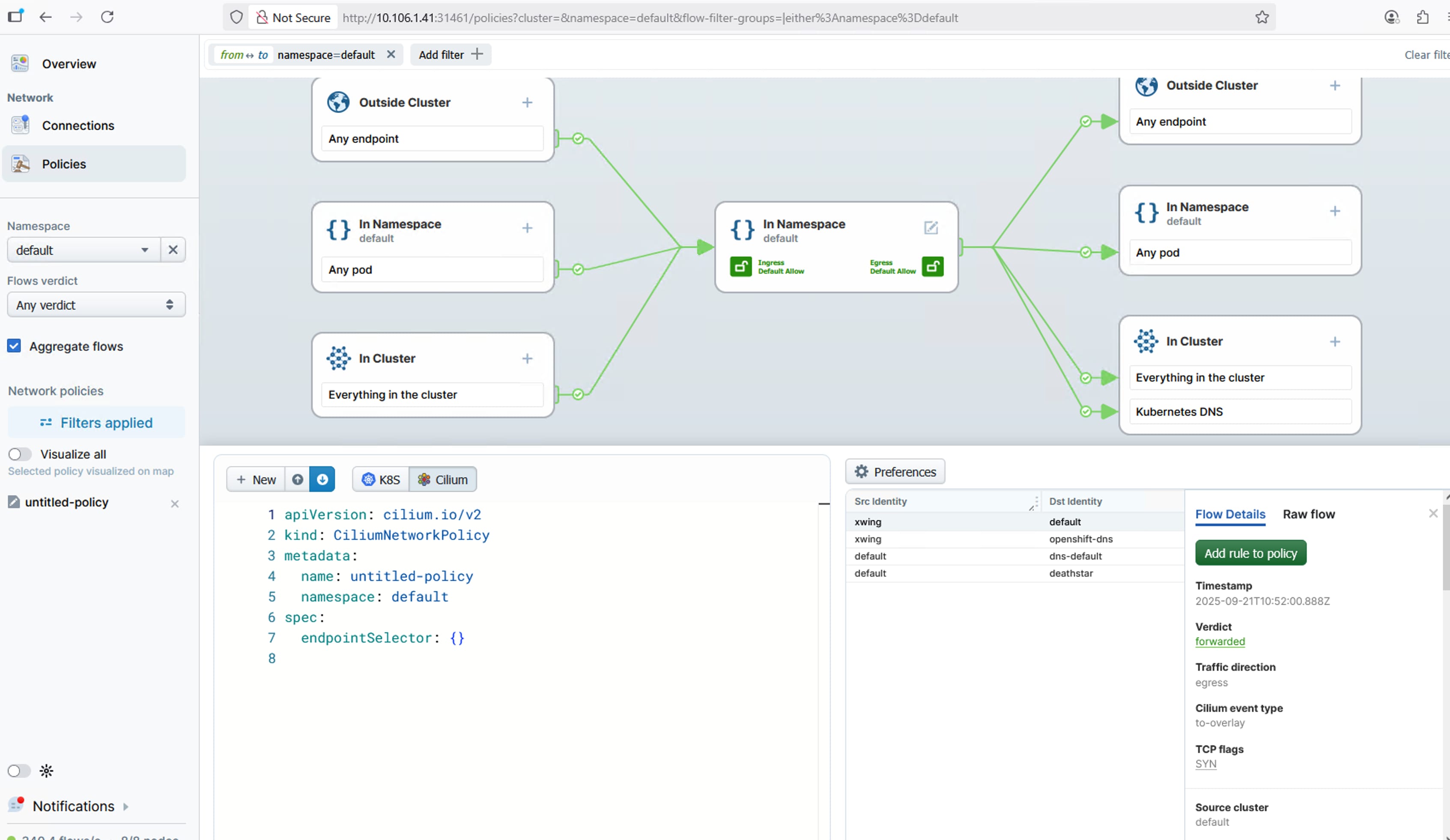
The usual flow of tasks creating a policy from a service map include:
● Observe Traffic: An administrator navigates to the Hubble Service Map in the Isovalent Enterprise UI. This view provides a real-time visualization of services and the traffic flowing between them.
● Select a Flow: The user identifies and clicks on a specific traffic flow (the line connecting two services) that they wish to authorize with a network policy.
● Generate the Policy: Upon selecting a flow, a context-aware side panel appears with details about the traffic. The user clicks the "Create Network Policy" button within this panel.
● Review and Apply: Hubble automatically generates the CiliumNetworkPolicy YAML required to allow that specific connection. The administrator can then review this auto-generated policy, make any necessary adjustments, and apply it to the cluster directly from the UI.
Install and Configure Portworx Enterprise on OpenShift with Pure Storage FlashArray
This chapter contains the following:
● Configure Physical Environment
● Deploy Portworx and Configure Storage Classes
● Portworx Enterprise Console Plugin for OpenShift
Portworx by Pure Storage is fully integrated with Red Hat OpenShift. Hence you can install and manage Portworx Enterprise from OpenShift web console itself. Portworx Enterprise can be installed with Pure Storage FlashArray as a cloud storage provider. This allows you to store your data on-premises with Pure Storage FlashArray while benefiting from Portworx Enterprise cloud drive features, such as:
● Automatically provisioning block volumes
● Expanding a cluster by adding new drives or expanding existing ones
● Support for PX-Backup and Autopilot
Portworx Enterprise creates and manages the underlying storage pool volumes on the registered arrays.
Note: Pure Storage recommends installing Portworx Enterprise with Pure Storage FlashArray Cloud Drives before using Pure Storage FlashArray Direct Access volumes.
These prerequisites must be met before installing the Portworx Enterprise on OpenShift with Pure Storage FlashArray:
● SecureBoot mode option must be disabled.
● The Pure Storage FlashArray should be time-synced with the same time service as the Kubernetes cluster.
● Pure Storage FlashArray must be running a minimum Purity//FA version of at least 4.8. Refer to the Supported models and versions topic for more information.
● Both multipath and iSCSI, if being used, should have their services enabled in systemd so that they start after reboots. These services are already enabled in systemd within the Red Hat CoreOS Linux.
Configure Physical Environment
Before you install Portworx Enterprise, ensure that your physical network is configured appropriately and that you meet the prerequisites. You must provide Portworx Enterprise with your Pure Storage FlashArray configuration details during installation:
● Each Pure Storage FlashArray management IP address can be accessed by each node.
● Your cluster contains an up-and-running Pure Storage FlashArray with an existing data plane connectivity layout (iSCSI, NVMe-TCP).
● If you're using iSCSI or NVMe-TCP, ensure the storage node initiators are on the same VLAN as the Pure Storage FlashArray iSCSI or NVMe-TCP target ports.
● For FC-based FlashStack design, ensure required zoning configuration is done on the MDS switches so that the compute nodes can access the volumes over FC protocol.
● You have an API token for a user on your Pure Storage FlashArray with at least storage_admin permissions.
● Ensure IP addresses have been assigned to the storage interfaces on each node and configured with MTU 9000. Verify all the workers reach target with large packet sizes without fragmenting the packets.
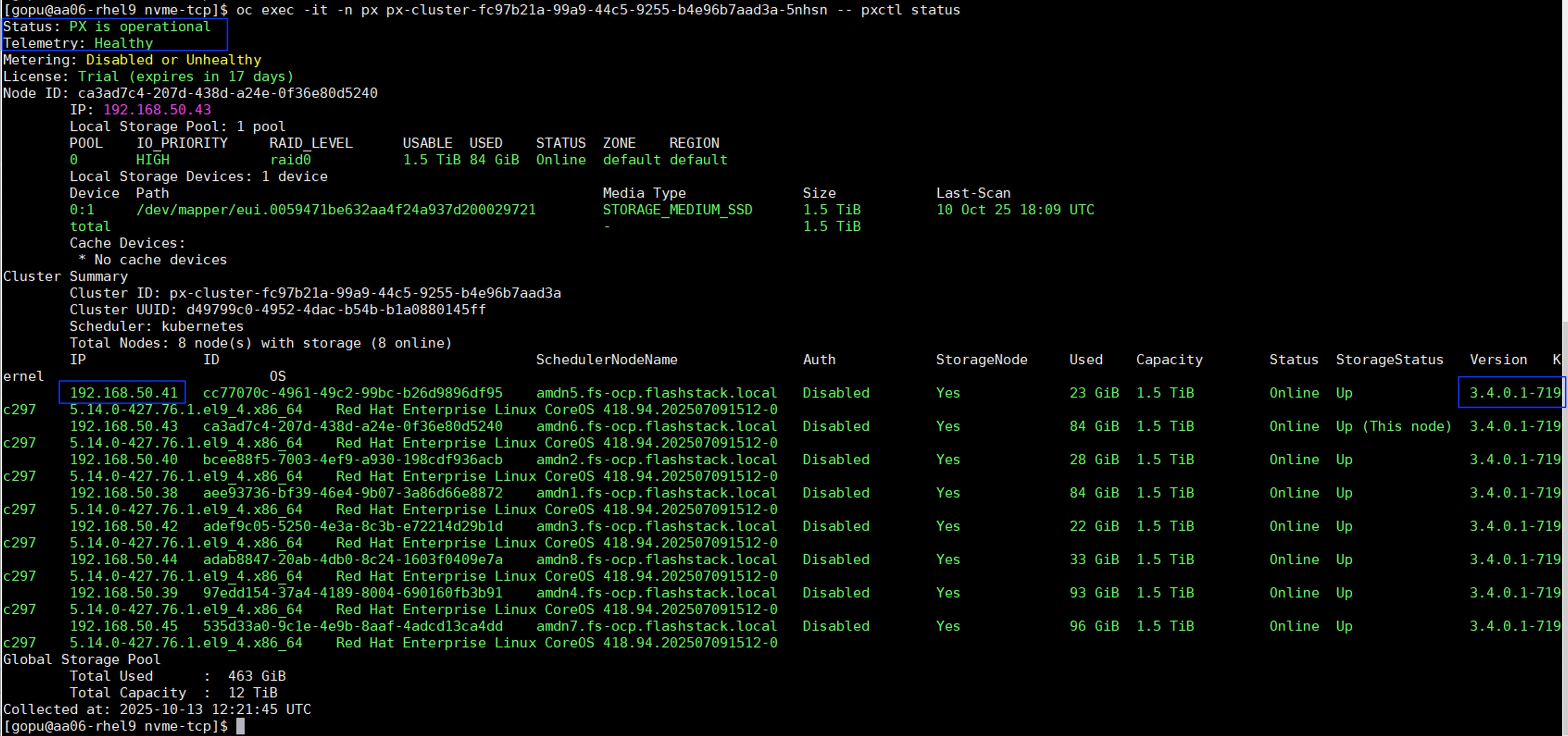
Procedure 1. Prepare for the Portworx Enterprise Deployment
Step 1. Secure the boot option already disabled at Intersight Boot Policy level. To reconfirm at the OS level, SSH into any of the worker node from the installer VM and ensure that SecureBoot mode is disabled at the OS level.
Step 2. Apply the following MachineConfig to the cluster configures each worker node with the following:
● Enable and start the multipathd.service with the specified multipath.conf configuration file.
● Enable and start the iscsid.service service.
● Applies the Queue Settings with Udev rules.
● Copy the /etc/nvme/discovery.conf file
The settings of multipath and Udev rules are defined as shown below:
##Storage target IPs for nvme-tcp connections
cat discovery.conf
# Used for extracting default parameters for discovery
#
# Example:
# --transport= --traddr= --trsvcid= --host-traddr= --host-iface=<host-iface>
--transport=tcp --traddr=192.168.51.4 --host-iface=eno7 -s 4420 -i 48
--transport=tcp --traddr=192.168.52.4 --host-iface=eno6 -s 4420 -i 48
--transport=tcp --traddr=192.168.51.5 --host-iface=eno7 -s 4420 -i 48
--transport=tcp --traddr=192.168.52.5 --host-iface=eno6 -s 4420 -i 48
## Multipath file to copied to /etc/multipath.conf
cat multipath.conf
defaults {
user_friendly_names no
enable_foreign "^$"
polling_interval 10
find_multipaths yes
}
devices {
device {
vendor "NVME"
product "Pure Storage FlashArray"
path_selector "queue-length 0"
path_grouping_policy group_by_prio
prio ana
failback immediate
fast_io_fail_tmo 10
user_friendly_names no
no_path_retry 0
features 0
dev_loss_tmo 60
}
device {
vendor "PURE"
product "FlashArray"
path_selector "service-time 0"
hardware_handler "1 alua"
path_grouping_policy group_by_prio
prio alua
failback immediate
path_checker tur
fast_io_fail_tmo 10
user_friendly_names no
no_path_retry 0
features 0
dev_loss_tmo 600
}
}
blacklist_exceptions {
property "(SCSI_IDENT_|ID_WWN)"
}
blacklist {
devnode "^pxd[0-9]*"
devnode "^pxd*"
device {
vendor "VMware"
product "Virtual disk"
}
}
## Dev rules to be used.
cat udevrules.txt
# Recommended settings for Pure Storage FlashArray.
# Use none scheduler for high-performance solid-state storage for SCSI devices
ACTION=="add|change", KERNEL=="sd*[!0-9]", SUBSYSTEM=="block", ENV{ID_VENDOR}=="PURE", ATTR{queue/scheduler}="none"
ACTION=="add|change", KERNEL=="dm-[0-9]*", SUBSYSTEM=="block", ENV{DM_NAME}=="3624a937*", ATTR{queue/scheduler}="none"
# Reduce CPU overhead due to entropy collection
ACTION=="add|change", KERNEL=="sd*[!0-9]", SUBSYSTEM=="block", ENV{ID_VENDOR}=="PURE", ATTR{queue/add_random}="0"
ACTION=="add|change", KERNEL=="dm-[0-9]*", SUBSYSTEM=="block", ENV{DM_NAME}=="3624a937*", ATTR{queue/add_random}="0"
# Spread CPU load by redirecting completions to originating CPU
ACTION=="add|change", KERNEL=="sd*[!0-9]", SUBSYSTEM=="block", ENV{ID_VENDOR}=="PURE", ATTR{queue/rq_affinity}="2"
ACTION=="add|change", KERNEL=="dm-[0-9]*", SUBSYSTEM=="block", ENV{DM_NAME}=="3624a937*", ATTR{queue/rq_affinity}="2"
# Set the HBA timeout to 60 seconds
ACTION=="add|change", KERNEL=="sd*[!0-9]", SUBSYSTEM=="block", ENV{ID_VENDOR}=="PURE", ATTR{device/timeout}="60"
The following is the MachineConfig file that takes the base64 encode results of the previous three files and copies them to the corresponding directory on each worker node. It also enables and starts iscsid and multipathd services. For FC-based FlashStack deployment, copy only multipath.conf and udev rules file (99-pure-storage.rules). Rest of the sections can be removed in the below script.
cat multipathmcp_worker.yaml
apiVersion: machineconfiguration.openshift.io/v1
kind: MachineConfig
metadata:
labels:
machineconfiguration.openshift.io/role: worker
name: 99-worker-multipath-iscsi-config
spec:
config:
ignition:
version: 3.2.0
storage:
files:
- contents:
source: 'data:text/plain;charset=utf-8;base64,ZGVmYXVsdHMgewogICAgdXNlcl9mcmllbmRseV9uYW1lcyBubwogICAgZW5hYmxlX2ZvcmVpZ24gIl4kIgogICAgcG9sbGluZ19pbnRlcnZhbCAgICAxMAogICAgZmluZF9tdWx0aXBhdGhzIHllcwp9CgpkZXZpY2VzIHsKICAgIGRldmljZSB7CiAgICAgICAgdmVuZG9yICAgICAgICAgICAgICAgICAgICAgICJOVk1FIgogICAgICAgIHByb2R1Y3QgICAgICAgICAgICAgICAgICAgICAiUHVyZSBTdG9yYWdlIEZsYXNoQXJyYXkiCiAgICAgICAgcGF0aF9zZWxlY3RvciAgICAgICAgICAgICAgICJxdWV1ZS1sZW5ndGggMCIKICAgICAgICBwYXRoX2dyb3VwaW5nX3BvbGljeSAgICAgICAgZ3JvdXBfYnlfcHJpbwogICAgICAgIHByaW8gICAgICAgICAgICAgICAgICAgICAgICBhbmEKICAgICAgICBmYWlsYmFjayAgICAgICAgICAgICAgICAgICAgaW1tZWRpYXRlCiAgICAgICAgZmFzdF9pb19mYWlsX3RtbyAgICAgICAgICAgIDEwCiAgICAgICAgdXNlcl9mcmllbmRseV9uYW1lcyAgICAgICAgIG5vCiAgICAgICAgbm9fcGF0aF9yZXRyeSAgICAgICAgICAgICAgIDAKICAgICAgICBmZWF0dXJlcyAgICAgICAgICAgICAgICAgICAgMAogICAgICAgIGRldl9sb3NzX3RtbyAgICAgICAgICAgICAgICA2MAogICAgfQogICAgZGV2aWNlIHsKICAgICAgICB2ZW5kb3IgICAgICAgICAgICAgICAgICAgIlBVUkUiCiAgICAgICAgcHJvZHVjdCAgICAgICAgICAgICAgICAgICJGbGFzaEFycmF5IgogICAgICAgIHBhdGhfc2VsZWN0b3IgICAgICAgICAgICAic2VydmljZS10aW1lIDAiCiAgICAgICAgaGFyZHdhcmVfaGFuZGxlciAgICAgICAgICIxIGFsdWEiCiAgICAgICAgcGF0aF9ncm91cGluZ19wb2xpY3kgICAgIGdyb3VwX2J5X3ByaW8KICAgICAgICBwcmlvICAgICAgICAgICAgICAgICAgICAgYWx1YQogICAgICAgIGZhaWxiYWNrICAgICAgICAgICAgICAgICBpbW1lZGlhdGUKICAgICAgICBwYXRoX2NoZWNrZXIgICAgICAgICAgICAgdHVyCiAgICAgICAgZmFzdF9pb19mYWlsX3RtbyAgICAgICAgIDEwCiAgICAgICAgdXNlcl9mcmllbmRseV9uYW1lcyAgICAgIG5vCiAgICAgICAgbm9fcGF0aF9yZXRyeSAgICAgICAgICAgIDAKICAgICAgICBmZWF0dXJlcyAgICAgICAgICAgICAgICAgMAogICAgICAgIGRldl9sb3NzX3RtbyAgICAgICAgICAgICA2MDAKICAgIH0KfQoKYmxhY2tsaXN0X2V4Y2VwdGlvbnMgewogICAgICAgIHByb3BlcnR5ICIoU0NTSV9JREVOVF98SURfV1dOKSIKfQoKYmxhY2tsaXN0IHsKICAgICAgZGV2bm9kZSAiXnB4ZFswLTldKiIKICAgICAgZGV2bm9kZSAiXnB4ZCoiCiAgICAgIGRldmljZSB7CiAgICAgICAgdmVuZG9yICJWTXdhcmUiCiAgICAgICAgcHJvZHVjdCAiVmlydHVhbCBkaXNrIgogICAgICB9Cn0K'
filesystem: root
mode: 420
overwrite: true
path: /etc/multipath.conf
- contents:
source: 'data:text/plain;charset=utf-8;base64,IyBSZWNvbW1lbmRlZCBzZXR0aW5ncyBmb3IgUHVyZSBTdG9yYWdlIEZsYXNoQXJyYXkuCiMgVXNlIG5vbmUgc2NoZWR1bGVyIGZvciBoaWdoLXBlcmZvcm1hbmNlIHNvbGlkLXN0YXRlIHN0b3JhZ2UgZm9yIFNDU0kgZGV2aWNlcwpBQ1RJT049PSJhZGR8Y2hhbmdlIiwgS0VSTkVMPT0ic2QqWyEwLTldIiwgU1VCU1lTVEVNPT0iYmxvY2siLCBFTlZ7SURfVkVORE9SfT09IlBVUkUiLCBBVFRSe3F1ZXVlL3NjaGVkdWxlcn09Im5vbmUiCkFDVElPTj09ImFkZHxjaGFuZ2UiLCBLRVJORUw9PSJkbS1bMC05XSoiLCBTVUJTWVNURU09PSJibG9jayIsIEVOVntETV9OQU1FfT09IjM2MjRhOTM3KiIsIEFUVFJ7cXVldWUvc2NoZWR1bGVyfT0ibm9uZSIKCiMgUmVkdWNlIENQVSBvdmVyaGVhZCBkdWUgdG8gZW50cm9weSBjb2xsZWN0aW9uCkFDVElPTj09ImFkZHxjaGFuZ2UiLCBLRVJORUw9PSJzZCpbITAtOV0iLCBTVUJTWVNURU09PSJibG9jayIsIEVOVntJRF9WRU5ET1J9PT0iUFVSRSIsIEFUVFJ7cXVldWUvYWRkX3JhbmRvbX09IjAiCkFDVElPTj09ImFkZHxjaGFuZ2UiLCBLRVJORUw9PSJkbS1bMC05XSoiLCBTVUJTWVNURU09PSJibG9jayIsIEVOVntETV9OQU1FfT09IjM2MjRhOTM3KiIsIEFUVFJ7cXVldWUvYWRkX3JhbmRvbX09IjAiCgojIFNwcmVhZCBDUFUgbG9hZCBieSByZWRpcmVjdGluZyBjb21wbGV0aW9ucyB0byBvcmlnaW5hdGluZyBDUFUKQUNUSU9OPT0iYWRkfGNoYW5nZSIsIEtFUk5FTD09InNkKlshMC05XSIsIFNVQlNZU1RFTT09ImJsb2NrIiwgRU5We0lEX1ZFTkRPUn09PSJQVVJFIiwgQVRUUntxdWV1ZS9ycV9hZmZpbml0eX09IjIiCkFDVElPTj09ImFkZHxjaGFuZ2UiLCBLRVJORUw9PSJkbS1bMC05XSoiLCBTVUJTWVNURU09PSJibG9jayIsIEVOVntETV9OQU1FfT09IjM2MjRhOTM3KiIsIEFUVFJ7cXVldWUvcnFfYWZmaW5pdHl9PSIyIgoKIyBTZXQgdGhlIEhCQSB0aW1lb3V0IHRvIDYwIHNlY29uZHMKQUNUSU9OPT0iYWRkfGNoYW5nZSIsIEtFUk5FTD09InNkKlshMC05XSIsIFNVQlNZU1RFTT09ImJsb2NrIiwgRU5We0lEX1ZFTkRPUn09PSJQVVJFIiwgQVRUUntkZXZpY2UvdGltZW91dH09IjYwIgo='
filesystem: root
mode: 420
overwrite: true
path: /etc/udev/rules.d/99-pure-storage.rules
- contents:
source: 'data:text/plain;charset=utf-8;base64,IyBVc2VkIGZvciBleHRyYWN0aW5nIGRlZmF1bHQgcGFyYW1ldGVycyBmb3IgZGlzY292ZXJ5CiMKIyBFeGFtcGxlOgojIC0tdHJhbnNwb3J0PTx0cnR5cGU+IC0tdHJhZGRyPTx0cmFkZHI+IC0tdHJzdmNpZD08dHJzdmNpZD4gLS1ob3N0LXRyYWRkcj08aG9zdC10cmFkZHI+IC0taG9zdC1pZmFjZT08aG9zdC1pZmFjZT4KLS10cmFuc3BvcnQ9dGNwIC0tdHJhZGRyPTE5Mi4xNjguNTEuNCAtLWhvc3QtaWZhY2U9ZW5vNyAtcyA0NDIwIC1pIDQ4Ci0tdHJhbnNwb3J0PXRjcCAtLXRyYWRkcj0xOTIuMTY4LjUyLjQgLS1ob3N0LWlmYWNlPWVubzYgLXMgNDQyMCAtaSA0OAotLXRyYW5zcG9ydD10Y3AgLS10cmFkZHI9MTkyLjE2OC41MS41IC0taG9zdC1pZmFjZT1lbm83IC1zIDQ0MjAgLWkgNDgKLS10cmFuc3BvcnQ9dGNwIC0tdHJhZGRyPTE5Mi4xNjguNTIuNSAtLWhvc3QtaWZhY2U9ZW5vNiAtcyA0NDIwIC1pIDQ4Cg=='
filesystem: root
mode: 420
overwrite: true
path: /etc/nvme/discovery.conf
systemd:
units:
- enabled: true
name: iscsid.service
- enabled: true
name: multipathd.service
For NVMe-TCP protocol implementation, create another MachineConfig file to ensure device mapper multipath is used instead of native nvme multipathing for managing nvme volumes over nvme-tcp. Output of command "cat /sys/module/nvme_core/parameters/multipath” should return ‘N’. This indicates native nvme multipath is supported but disabled:
cat tcp-nvme-disable-native-nvme-multipath-worker.yaml
apiVersion: machineconfiguration.openshift.io/v1
kind: MachineConfig
metadata:
labels:
machineconfiguration.openshift.io/role: worker
name: 99-worker-disable-nvme-multipath-worker
spec:
config:
ignition:
version: 3.4.0
kernelArguments:
- nvme_core.multipath=N
Step 3. Apply the machine configuration files:
oc apply -f multipathmcp_worker.yaml
oc apply -f tcp-nvme-disable-native-nvme-multipath-worker.yaml
Note: If using combined control plane and worker nodes (mixed OpenShift deployment), separate files for workers and masters (control-plane) need to be created for each MachineConfig file. For creating MachineConfig files for control-plane nodes, create files by setting “machineconfiguration.openshift.io/role” to “master”.
Step 4. This machine config is applied to each worker node one by one. To view the status of this process, from the cluster console go to Administration > Cluster Settings.
Step 5. After the MachineConfig is applied on all the worker nodes, ssh into one of the worker nodes and verify if the two files multipath.conf and 99-pure-stroage.rules are created and iscsid and multipathd services are running.

Step 6. The hostnqn (NVMe Host NQN) is expected to be a unique identifier, often generated using the UUID of the host system. However, in some OpenShift deployments, particularly during the installer boot process, duplicate NQNs are observed across different nodes, meaning multiple nodes end up with the same hostnqn. For this validation, we used the “nvme gen-hostnqn" command that generates a unique hostnqn id using host’s UUID. Host UUID is assigned from the Intersight UUID pool. For this, you need to connect to each worker node using the “oc debug node/<nodename> command and generate the hostnqn id as shown below:
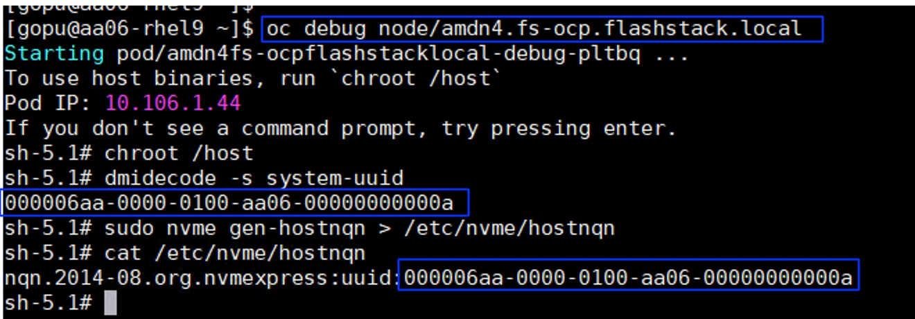
Step 7. Create Kubernetes secret object constituting the Pure Storage FlashArray API endpoints and API Tokens that Portworx Enterprise needs to communicate with and manage the Pure Storage FlashArray storage device.
Step 8. Log into Pure Storage FlashArray and go to Settings > Users and Polices. Create a dedicated user (for instance, ocp-user) with storage Admin role for Portworx Enterprise authentication.
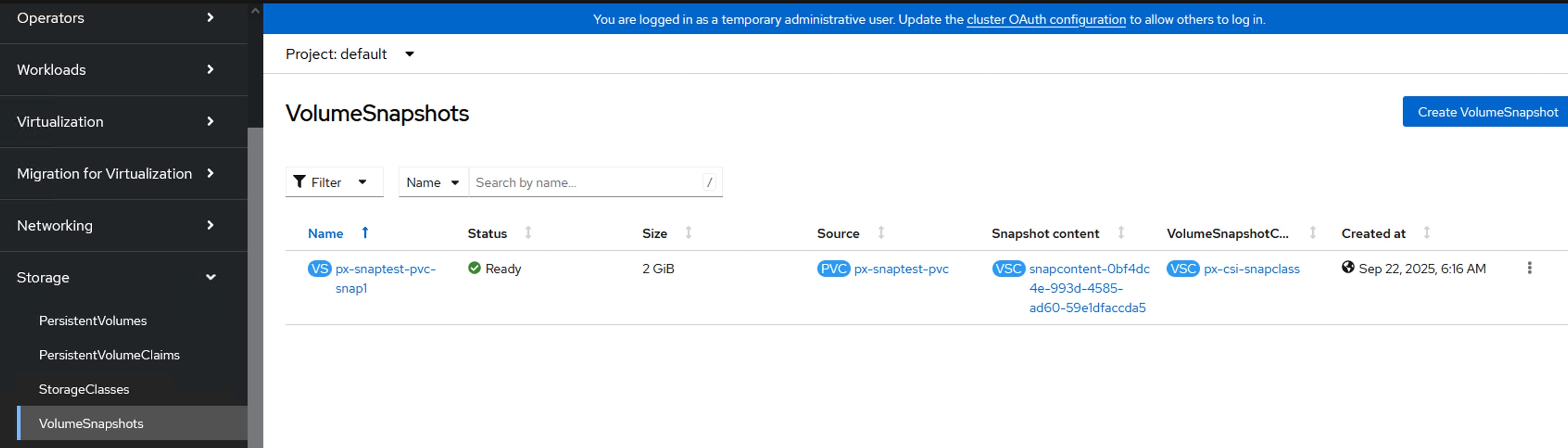
Step 9. Click the ellipses of the previously created user and select Create API Token. In the Create API Token wizard, set the number of weeks (for instance 24) for the API key to expire and click Create. A new API Token for the ocp-user is created and displays. Copy the API key and preserve it since it will be used later to create Kubernetes Secret.
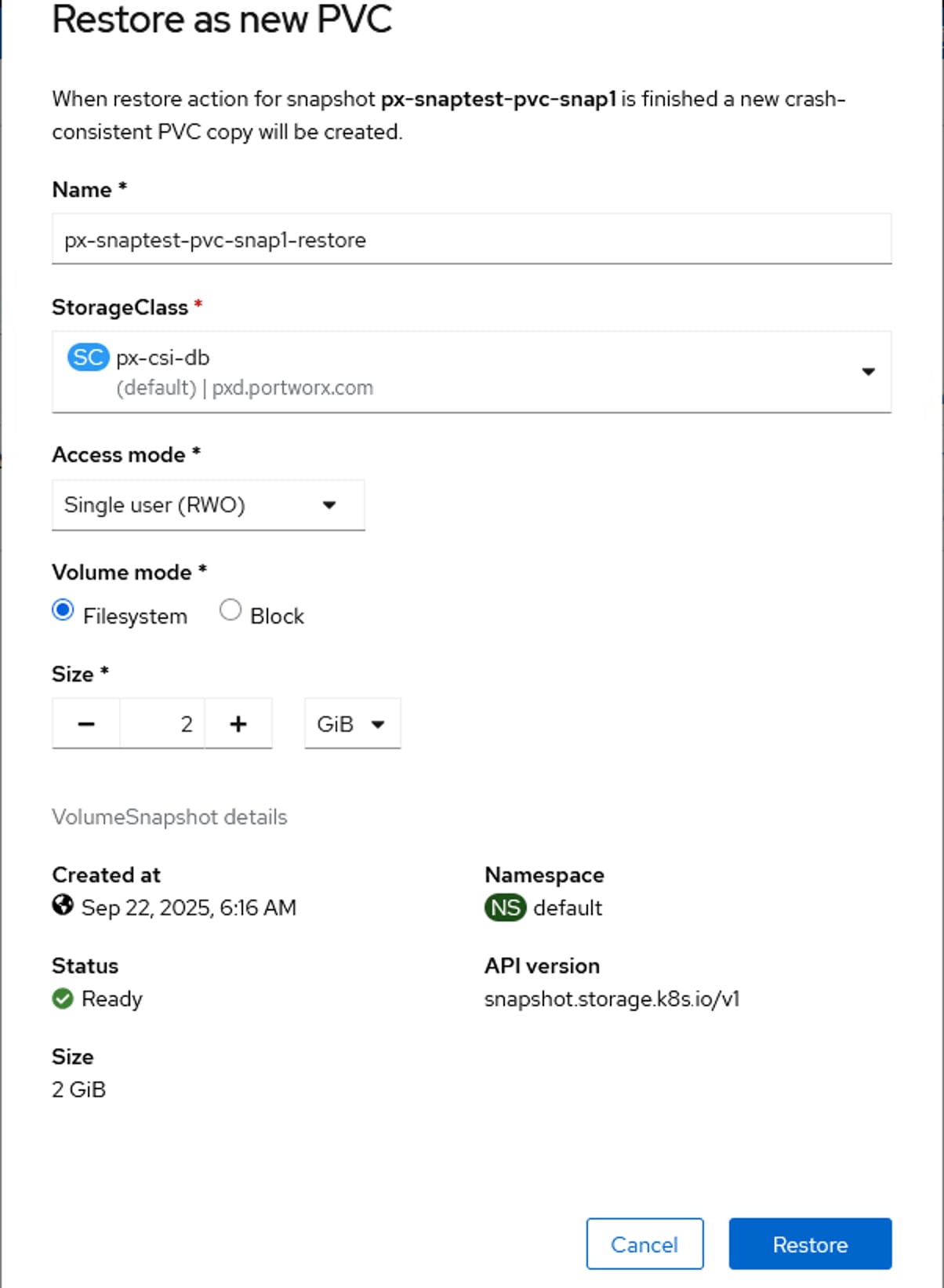
Step 10. Create Kubernetes secret with the API key (located above) using the following manifest:
## Create a json file constituting FlashArray Management IP addresses and API key created in the above step.
cat pure.json
{
"FlashArrays": [
{
"MgmtEndPoint": "10.103.0.55",
"APIToken": "< your API KEY >"
}
]
}
## secret name must match with below name
kubectl create secret generic px-pure-secret --namespace px --from-file=pure.json
Note: If multiple arrays configured with Availability Zones labels (AZs) are available, then you can use these AZ topology labels and enter those into pure.json to distinguish the arrays. For more details, go to: https://docs.portworx.com/portworx-enterprise/operations/operate-kubernetes/cluster-topology/csi-topology
Deploy Portworx and Configure Storage Classes
This section covers the steps for deploying Portworx Storage Cluster and creating Storage Classes for dynamic storage provisioning of ReadWriteMany (RWX) volumes.
Procedure 1. Deploy Portworx Enterprise
Step 1. Log into the OpenShift cluster console using the kubeadmin account and go to Operators > OperatorHub.
Step 2. In the right pane, enter Portworx Enterprise to filter the available operators in the Operator Hub. Select Portworx Enterprise and click Install.
Step 3. In the Operator Installation window, from the Installed Namespace drop-down list, select Create Project and create a new project (for instance, px) and select the newly created project to install the Portworx Operator.
Step 4. Install the Portworx plugin for OpenShift by clicking Enable under the Console Plugin. Click Install.
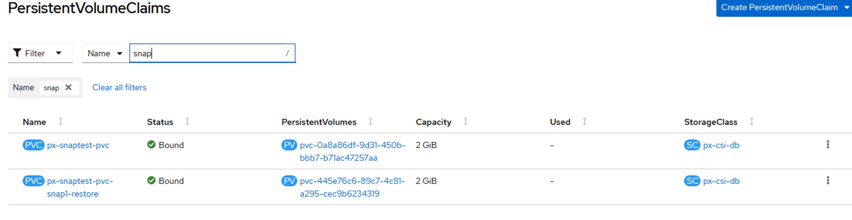
Note: The Portworx Console Plugin for OpenShift will be activated and shown only after installing the StorageCluster. Follow the below steps to create Portworx StorageCluster.
Step 5. When the Portworx operator is successfully installed, the StorageCluster needs to be created. To create the StorageCluster Specifications (manifest file) log into https://central.portworx.com/ and use your credentials and click Get Started.
Step 6. Select Portworx Enterprise and click Continue.
Step 7. From the Generate Spec page, select the latest Portworx version (version 3.4 was the latest when this solution was validated). Select Pure Storage FlashArray as the platform. Select OpenShift 4+ from the Distribution drop-down list, provide px for the Namespace field. Click Customize.
Step 8. Get the Kubernetes version by running kubectl version | grep -i 'Server Version'. Click Next.
Step 9. From the Storage tab, select required protocol for the deployment. In this CVD, iSCSI, Fibre Channel and NVMe-OF- TCP options are validated. Provide the size of the Cloud drive (1500GB) and click plus (+) to add additional disks. Click Next.
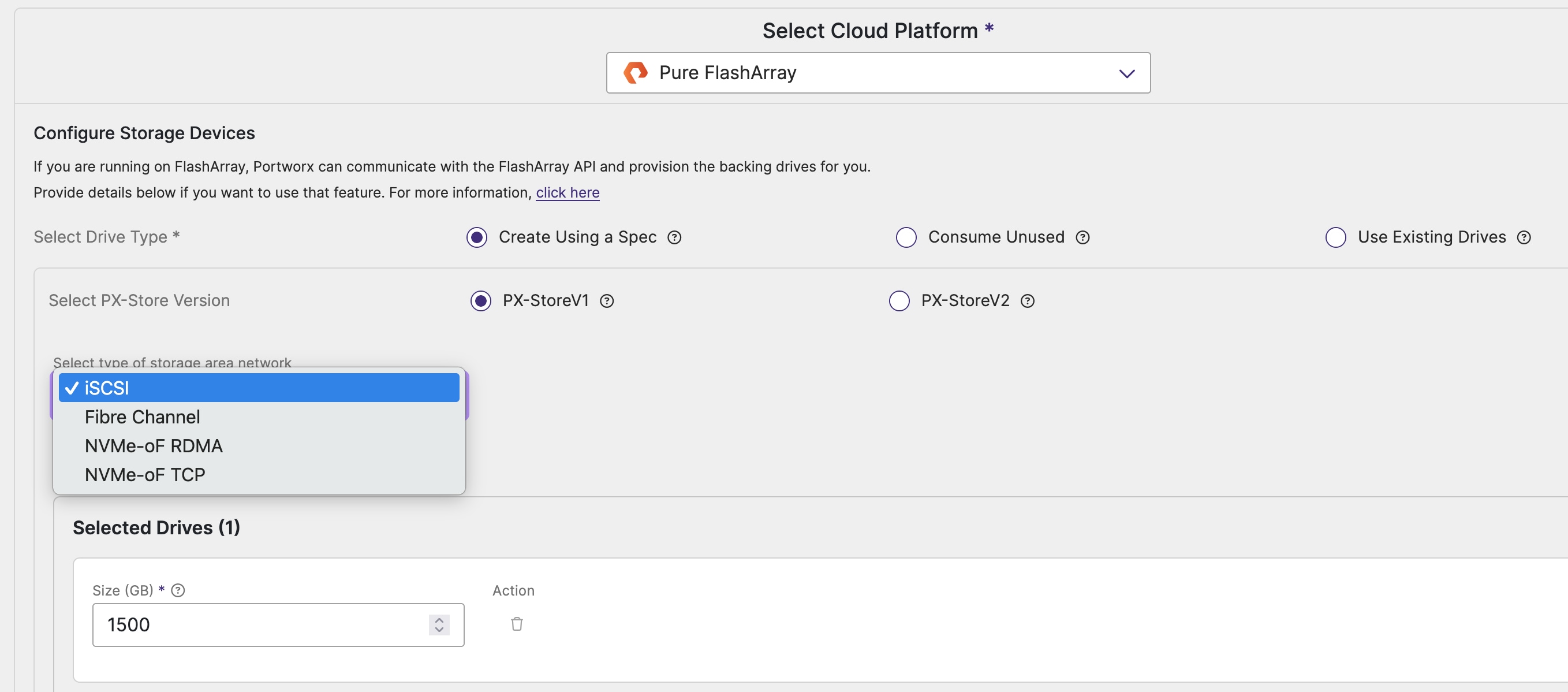
Step 10. In the Network tab, set eno12 for Data Network Interface. Click Next.
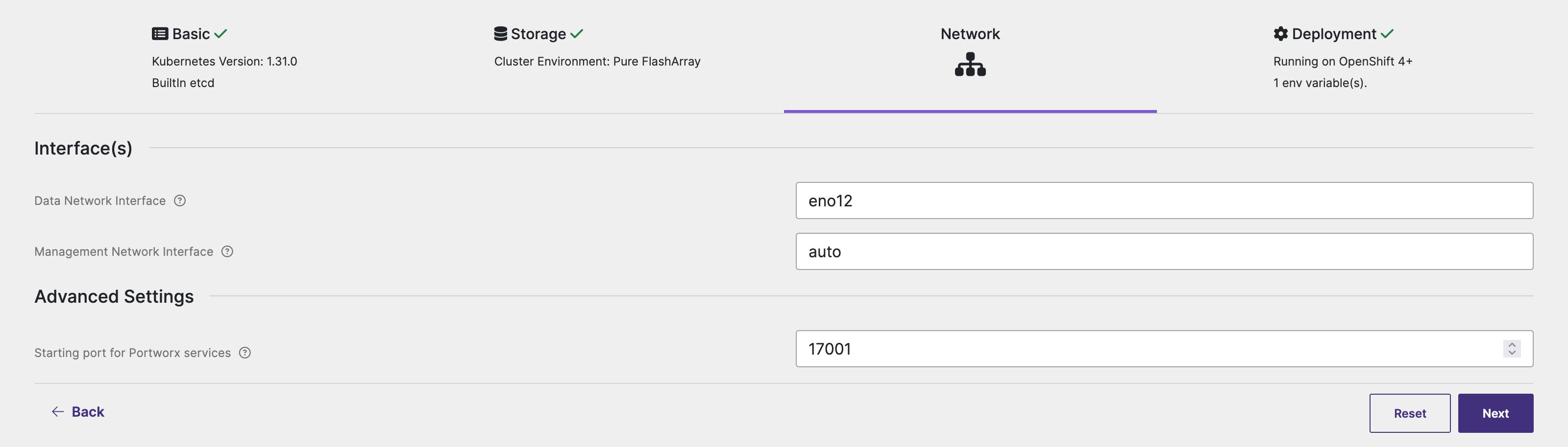
Step 11. Click Next. Under Environment Variables, add the variable and value as shown below for IP-Based FlashStack deployment:
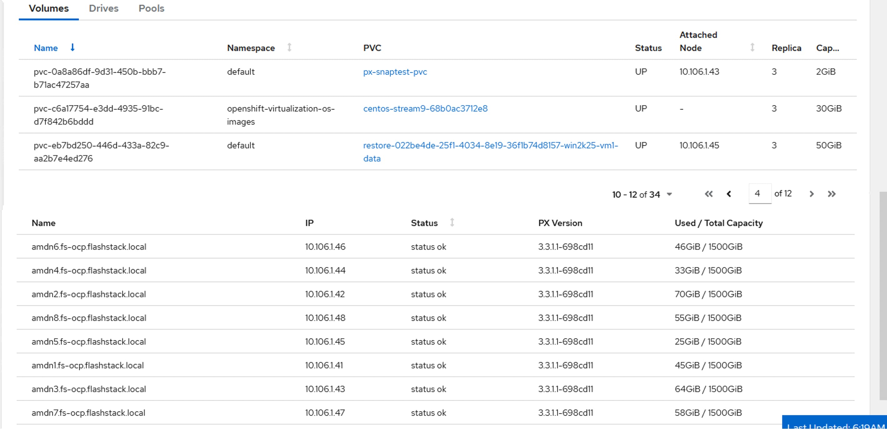
Note: Ensure to enter both the iSCSI network subnets. This enables the volumes on the workers nodes to leverage all the available data paths to access target volumes.
Step 12. Click Advanced Settings, enter the name of the portworx cluster (for instance, ocp-pxclus). Click Finish. Click Download.yaml to download the StorageCluster specification file.
Step 13. From the OpenShift console, go to Operators > Installed Operators > Portworx Enterprise. Click the StorageCluster tab and click Create Storage Cluster to create StorageCluster. This opens the YAML view of Storage Cluster.
Step 14. Copy the contents of the spec file previously downloaded and paste it in the yaml body. Verify that both the iSCSI/NVMe-TCP subnet networks are listed under env: as shown below. Click Create to create the StorageCluster. The following image shows environmental variables used for Portworx deployment with nvme-tcp. For iSCSI deployment, set PURE_FLASHARRAY_SAN_TYPE to “ISCSI” and for FC deployment, set PURE_FLASHARRAY_SAN_TYPE to “FC.”
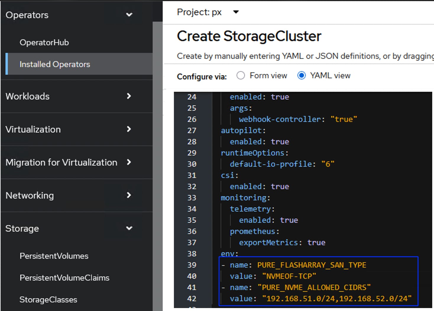
Step 15. Wait until all the Portworx related pods come online.
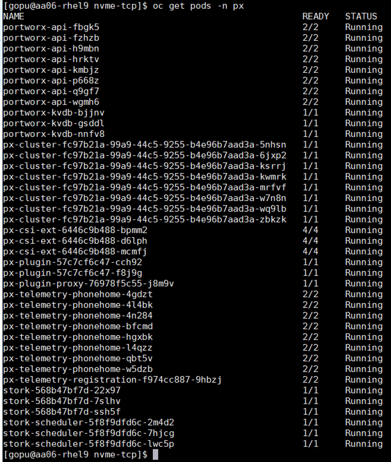
Step 16. Verify the cluster status by running the command on any worker node: sudo /opt/pwx/bin/pxctl status.

Step 17. Run the sudo multipath -ll command on one of the worker nodes to verify all four paths (for both IP and FC based deployments) from the worker node to storage target are being used. The following screen shots shows settings for nvme-tcp deployment:
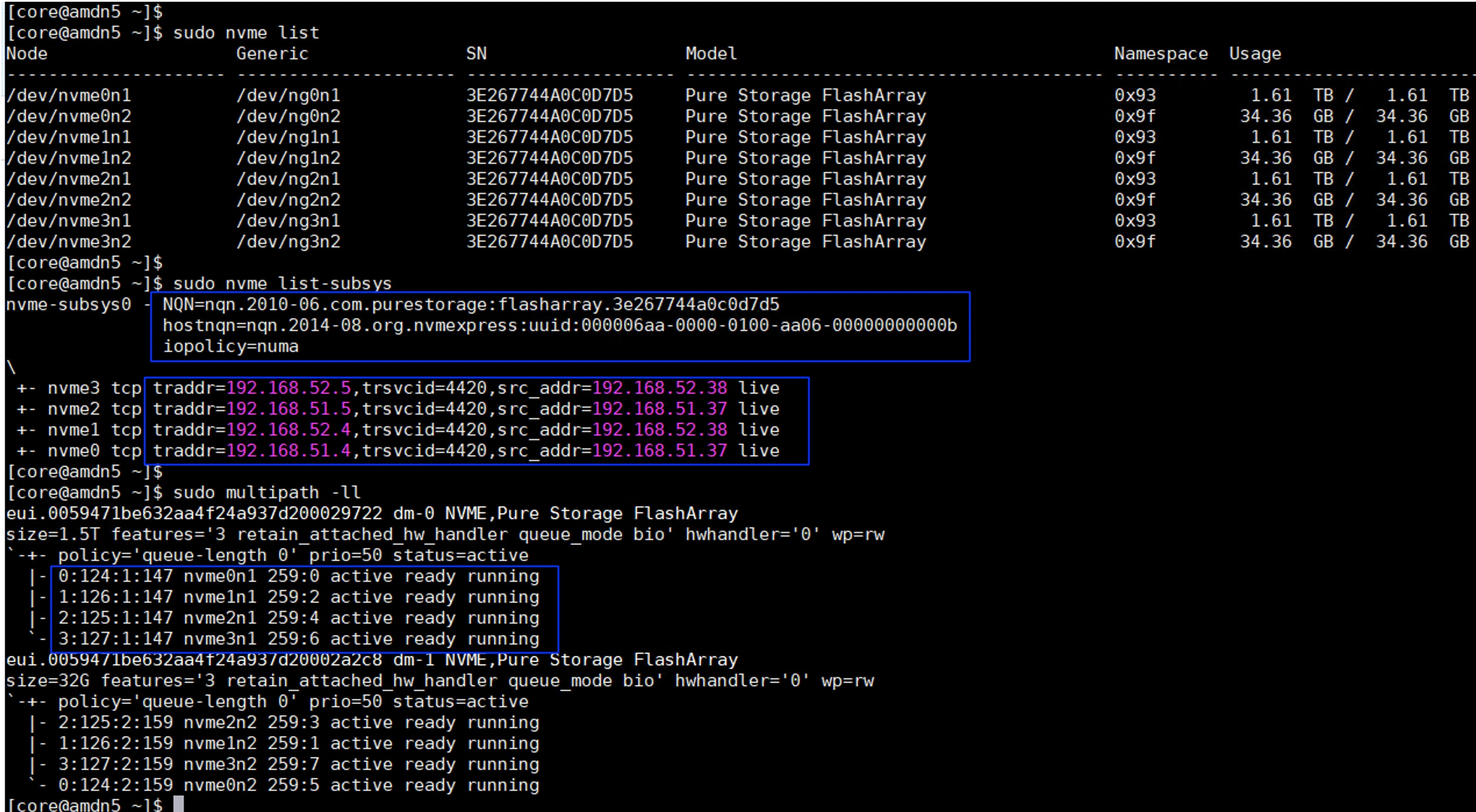
Step 18. Verify how FlashArray hosts are created and configured for each of the portworx storage node in the FlashArray. The following image shows the hosts created for nvme-tcp deployment:
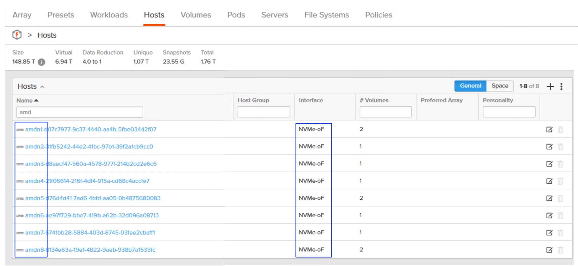
Procedure 2. Dynamic Volume Provisioning and Data Protection
Portworx by Pure Storage offers a set of pre-configured storage classes out of the box for various use cases. These storage classes support CSI features and dynamic provisioning. You are advised to choose from the available out-of-the-box storage classes for traditional use cases.
The list of preconfigured storage using the pxd.portworx.com provisioner implementing kubernetes CSI specifications for Portworx is shown below:
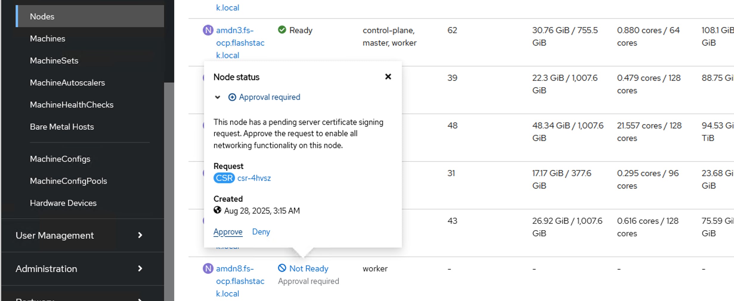
Step 1. Execute oc describe sc <sc-name> commands to view various parameters used by each Storage Class. For more details on the storage class parameters go to: https://docs.portworx.com/portworx-enterprise/platform/provision-storage/create-pvcs/dynamic-provisioning.
Step 2. Run the following command to set the Storage Class as the default Storage Class:
oc patch storageclass <your storage class Name> -p '{"metadata": {"annotations":{"storageclass.kubernetes.io/is-default-class":"true"}}}'
To enable special features such as KubeVirt VM live migration and use cases that require shared filesystem volumes across multiple pods, Portworx supports the ReadWriteMany(RWX) Block and File System volumes. The following are some of the available options:
● Shared File System Volumes (sharedV4 volumes): These volumes allow multiple pods ( across the nodes) to read and write the same volume simultaneously. The file system level abstraction, access, and permission will be managed care by Portworx’s Sharedv4. These sharedv4 volumes are best suited for most RWX workloads in kubernetes. Some of the typical use cases that use sharedV4 volumes are web servers accessing shared file system volumes, Logs aggregation and so on. These shared file system volumes can be used for provisioning OS and Data disks for the OpenShift virtual machines. These shared disks support RWX option for enabling VMs live migration within the OpenShift cluster. The Storage Class provided below provides shared file system volumes for KubeVirt VMs.
cat px-rwx-kubevirt.yaml
allowVolumeExpansion: true
apiVersion: storage.k8s.io/v1
kind: StorageClass
metadata:
name: px-rwx-kubevirt
annotations:
storageclass.kubernetes.io/is-default-class: "false"
provisioner: pxd.portworx.com
parameters:
repl: "2"
sharedv4: "true"
sharedv4_mount_options: vers=3.0,nolock
sharedv4_svc_type: ""
reclaimPolicy: Retain
volumeBindingMode: Immediate
## create the storage class px-rwx-kubevirt
oc apply -f px-rwx-kubevirt.yaml
● Shared Block Devices (RWX Block): The shared block devices provide shared access (RWX) at the block level hence recommended to use them in specific scenarios like KubeVirt VM live migration. As the volumes are accessed at the block level, these shared block volumes provide better performance compared to shared file system volumes. Ensure to use these shared block volumes only for the cluster-aware applications like clustered file systems or databases. The Storage Class provided below provides shared block volumes for KubeVirt VMs.
cat px-rwx-block-kubevirt.yaml
apiVersion: storage.k8s.io/v1
kind: StorageClass
metadata:
name: px-rwx-block-kubevirt
provisioner: pxd.portworx.com
parameters:
repl: "3"
nodiscard: "true" # Disables discard operations on the block device to help avoid known compatibility issues on OpenShift Container Platform (OCP) versions 4.18 and earlier.
volumeBindingMode: Immediate
allowVolumeExpansion: true
## create the storage class px-rwx-block-kubevirt
oc apply -f px-rwx-block-kubevirt.yaml
● FlashArray Direct Access Shared Block Device: Portworx enables the seamless integration of KubeVirt virtual machines (VMs) within Kubernetes clusters, leveraging the high performance of ReadWriteMany (RWX) volumes backed by FlashArray Direct Access (FADA) shared raw block RWX volumes. This approach supports raw block devices, which provide direct block storage access instead of a mounted filesystem. This is particularly beneficial for applications that demand low-latency and high-performance storage. These volumes eliminate filesystem overhead, provide direct access to the underlying storage for improved performance and enable efficient live migration of VMs in OpenShift clusters.
cat px-fada-sc.yaml
apiVersion: storage.k8s.io/v1
kind: StorageClass
metadata:
name: px-fada-rwx-sc
parameters:
backend: "pure_block"
provisioner: pxd.portworx.com
volumeBindingMode: WaitForFirstConsumer
allowVolumeExpansion: true
## create the storage class px-fada-rwx-sc
oc apply -f px-fada-sc.yaml
This section provides the procedures to create SnapshotClass for enabling snapshots of PVCs and also explains clones.
Snapshots and Clones: Portworx Enterprise offers data protection of volumes using volume snapshots and restore them for point in time recovery of the data. Any Storage Class that implements portworx csi driver pxd.portworx.com supports volume Snapshots.
Procedure 1. Create volume snapshots and clones
Step 1. Run the following scripts to create the VolumeSnapshotClass and a PVC. Then create Snapshot of the PVC and restore the snapshot as a new PVC.
## For Openshift platform, px-csi-account service account needs to be added to the privileged security context.
oc adm policy add-scc-to-user privileged system:serviceaccount:kube-system:px-csi-account
## Now creat VolumeSnapshotClass using below manifest
## cat VolumeStroageClass.yaml
apiVersion: snapshot.storage.k8s.io/v1
kind: VolumeSnapshotClass
metadata:
name: px-csi-snapclass
annotations:
snapshot.storage.kubernetes.io/is-default-class: "true"
driver: pxd.portworx.com
deletionPolicy: Delete
parameters:
csi.openstorage.org/snapshot-type: local
Step 2. Use the following sample manifest to create a sample PVC:
## cat px-snaptest-pvc.yaml
kind: PersistentVolumeClaim
apiVersion: v1
metadata:
name: px-snaptest-pvc
spec:
storageClassName: px-csi-db. ## Any Storage Class can be used which implements Portworx CSI driver.
accessModes:
- ReadWriteOnce
resources:
requests:
storage: 2Gi
## Assume this pvc is attached to a pod and the pod has written some data into the pvc.
## Now create Snapshot of the above volume. It can be created using UI also.
## cat create-snapshot-snaptest-pvc.yaml
apiVersion: snapshot.storage.k8s.io/v1
kind: VolumeSnapshot
metadata:
name: px-snaptest-pvc-snap1
spec:
volumeSnapshotClassName: px-csi-snapclass
source:
persistentVolumeClaimName: px-snaptest-pvc. ## the name of the pvc
The following image shows px-snaptest-pvc-snap1 is the snapshot of the PVC px-snaptest-pvc:
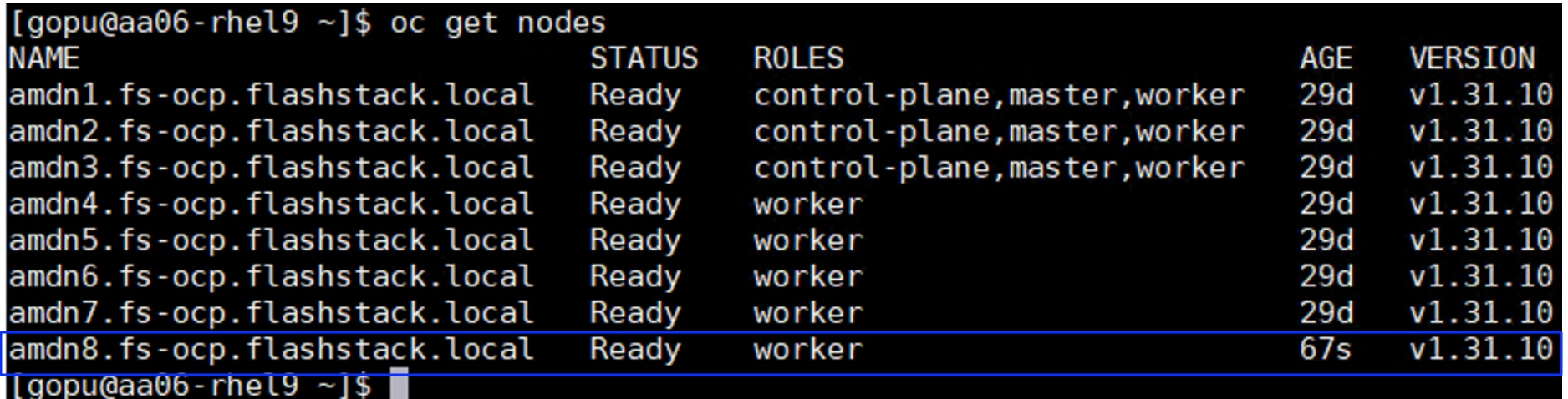
Step 3. You can now restore this snapshot as a new PVC, and it can be mounted to other pods.
Step 4. Click the ellipses of the snapshot and select Restore as new PVC. In the Restore as new PVC window, click Restore.
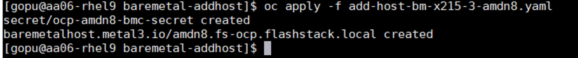
Step 5. You can view the original and restored PVC under PVC list.
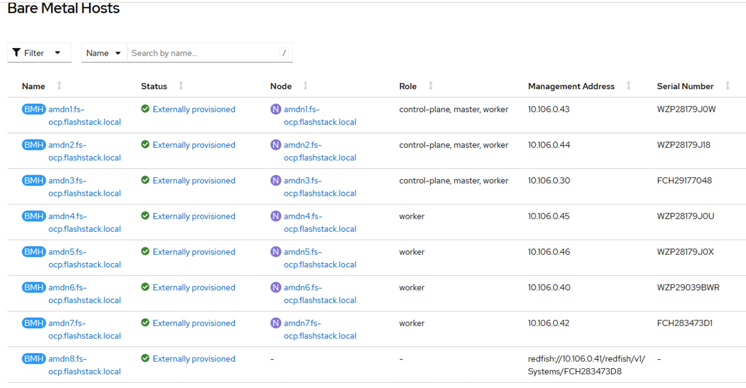
Step 6. To clone PVC (px-snaptest-pvc), click three of the PVC and select Clone PVC. Click Clone.
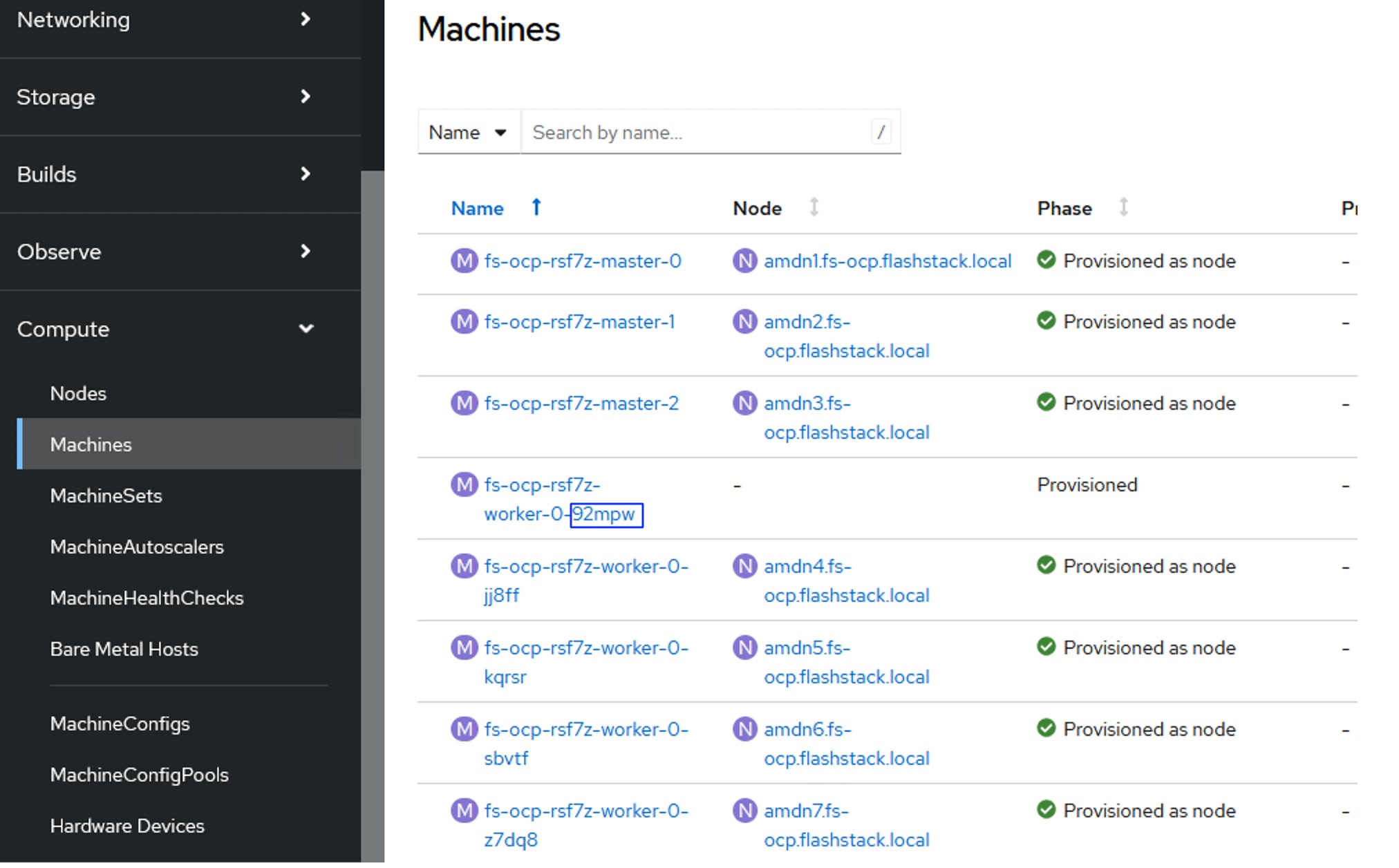
Portworx Enterprise Console Plugin for OpenShift
Portworx by Pure Storage has built an OpenShift Dynamic console plugin that enables single-pane-of-glass management of storage resources running on Red Hat OpenShift clusters. This allows platform administrators to use the OpenShift web console to manage not just their applications and their OpenShift cluster, but also their Portworx Enterprise installation and their stateful applications running on OpenShift.
This plugin can be installed with a single click during the Installation of Portworx Operator. Once the plugin is enabled, the Portworx Operator automatically installs the plugin pods in the same OpenShift project as the Portworx storage cluster. When the pods are up and running, administrators will see a message in the OpenShift web console to refresh their browser window for the Portworx tabs to show up in the UI.
With this plugin, Portworx has built three different UI pages, including a Portworx Cluster Dashboard that displays in the left navigation menu, a Portworx tab under Storage > Storage Class section, and another Portworx tab under Storage > Persistent Volume Claims.
Portworx Cluster Dashboard
Platform administrators can use the Portworx Cluster Dashboard to monitor the status of their Portworx Storage Cluster and their persistent volumes and storage nodes. Here are a few operations that are now streamlined by the OpenShift Dynamic plugin from Portworx.
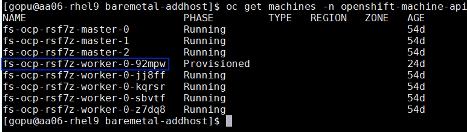
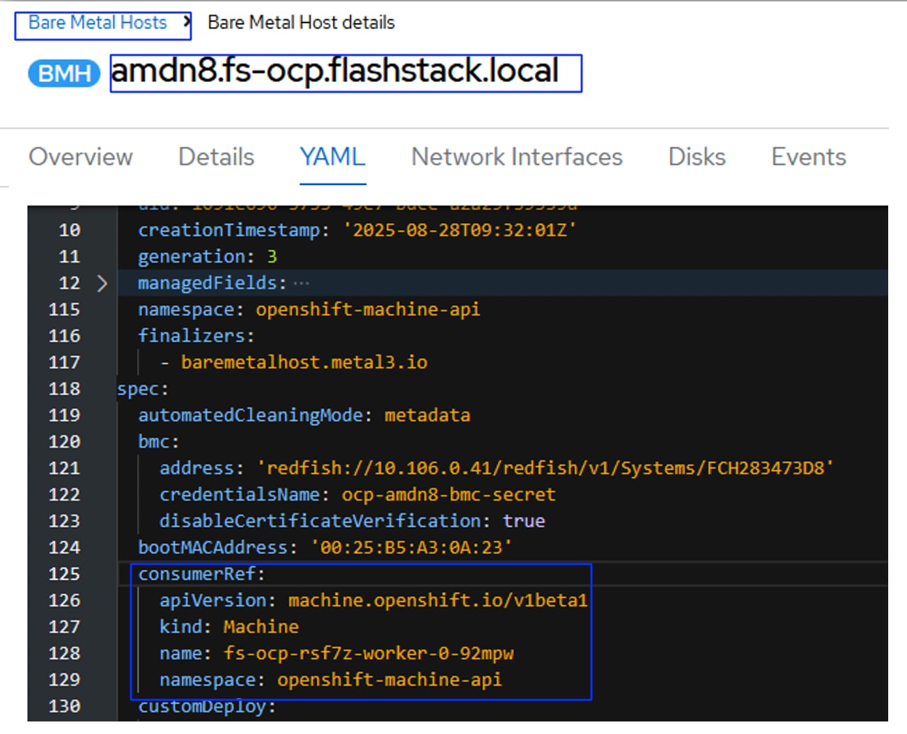
To view detailed inventory about the Portworx Cluster, click the Drives and Pools tabs.
Portworx PVC Dashboard
This dashboard contains some of the important attributes of the PVC Replication Factor, node details of replicas, attached node, and so on. Previously, you would have had to use multiple pxctl inspect volume CLI commands to obtain these details. Now all this information can be found in Console Plugin.
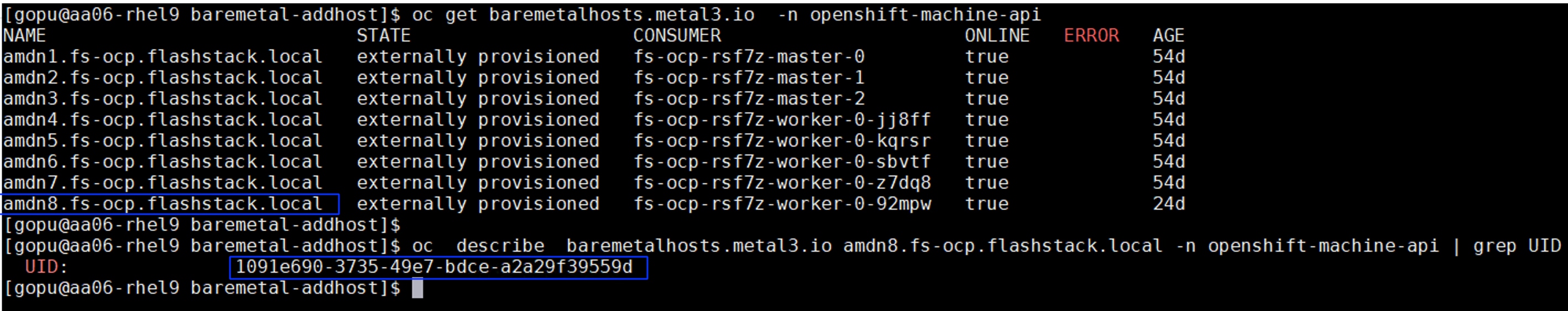
Portworx StorageClass Dashboard
From the Portworx storage cluster tab, administrators can get details about the custom parameters set for each storage class, the number of persistent volumes dynamically provisioned using the storage class, and a table that lists all the persistent volumes deployed using that storage class. The OpenShift dynamic plugin eliminates the need for administrators to use multiple “kubectl get” and “kubectl describe” commands to find all these details—instead, they can just use a simple UI to monitor their storage classes.
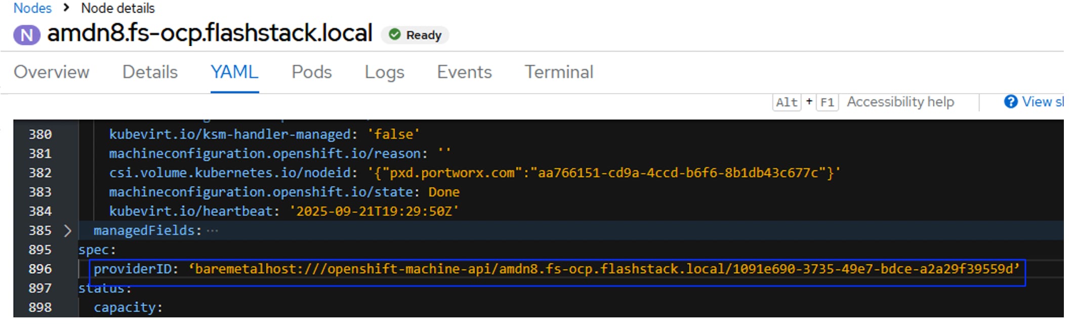
Add a Worker Node to an OpenShift Cluster
This chapter contains the following:
This chapter provides the procedures to scale-up the worker nodes of OpenShift cluster by adding a new worker node to the existing cluster. For this exercise, a UCS X215 M8 blade will be added as a new worker node as amdn8.fs-ocp.flashstack.local to the already existing OpenShift cluster.
Note: This chapter assumes that a new Intersight server profile is already derived from the same template and assigned to the new server successfully.
This section details how to create and configure an OpenShift Cluster expansion.
Procedure 1. Create and configure the OpenShift Cluster
Step 1. Launch a web browser and go to https://console.redhat.com/openshift/cluster-list. Log into your Red Hat account.
Step 2. Click your cluster name and go to Add Hosts.
Step 3. Under Host Discovery, click Add hosts.
Step 4. In the Add hosts wizard, for the CPU architecture select x86_64 and for the Host’s network configuration select DHCP Only. Click Next.
Step 5. For the Provision type select Full image file from the drop-down list, for SSH public key browse or copy/paste the contents of id-ed25519.pub file. Click Generate Discovery ISO and when the file is generated and click Download Discovery ISO file.
Step 6. Click Add hosts from Cisco Intersight and select the node from the intersight. Click Save. Click Execute. This will mount the Discovery ISO to the host and boot the server into it.
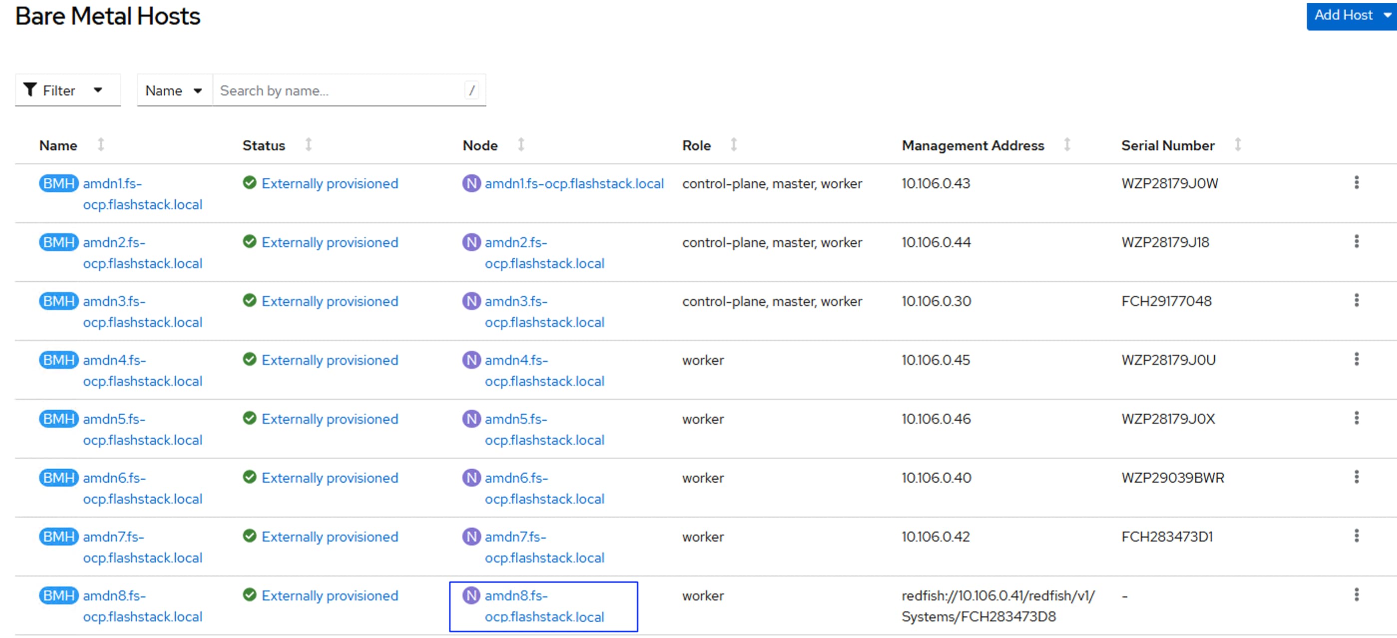
When the server has booted RHEL CoreOS (live) from the newly generated Discovery ISO, it will appear in the assisted installer under Add hosts:
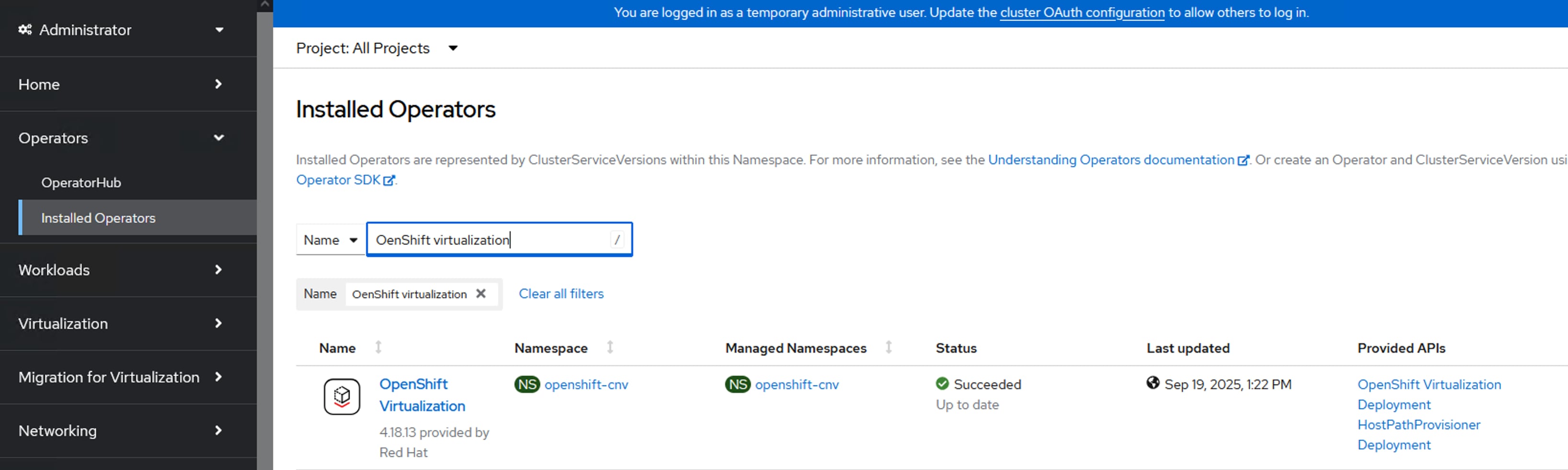
Note: If you see insufficient warning messages for the node due to missing ntp server information, expand one of the nodes, click Add NTP Sources and provide the NTP servers IPs separated by a comma.
Note: If a warning message appears stating you have multiple network devices on the L2 network, ssh into worker node and deactivate eno8,eno9, and eno10 interfaces using the nmtui utility.
Step 7. When the node status shows Ready, click Install ready hosts. After few minutes, the required components will be installed on the node and displays the status as Installed.
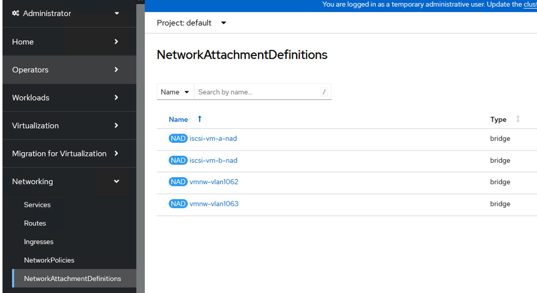
Step 8. Log into the cluster with kubeadmin user and go to Compute > Nodes > and select the newly added worker node and approve the Cluster join request of the worker node and request for server certificate signing.
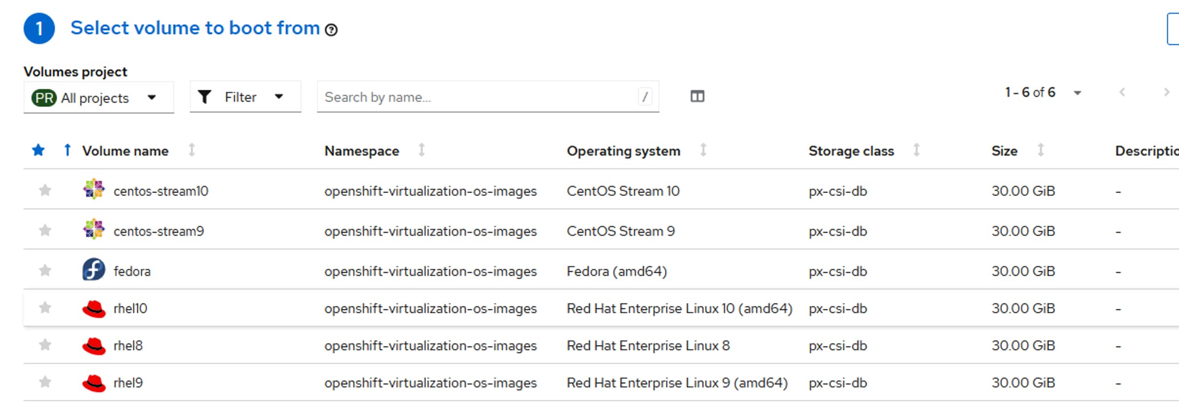
Step 9. Wait for a few seconds and the node will be ready, and the pods are scheduled on the newly added worker node.
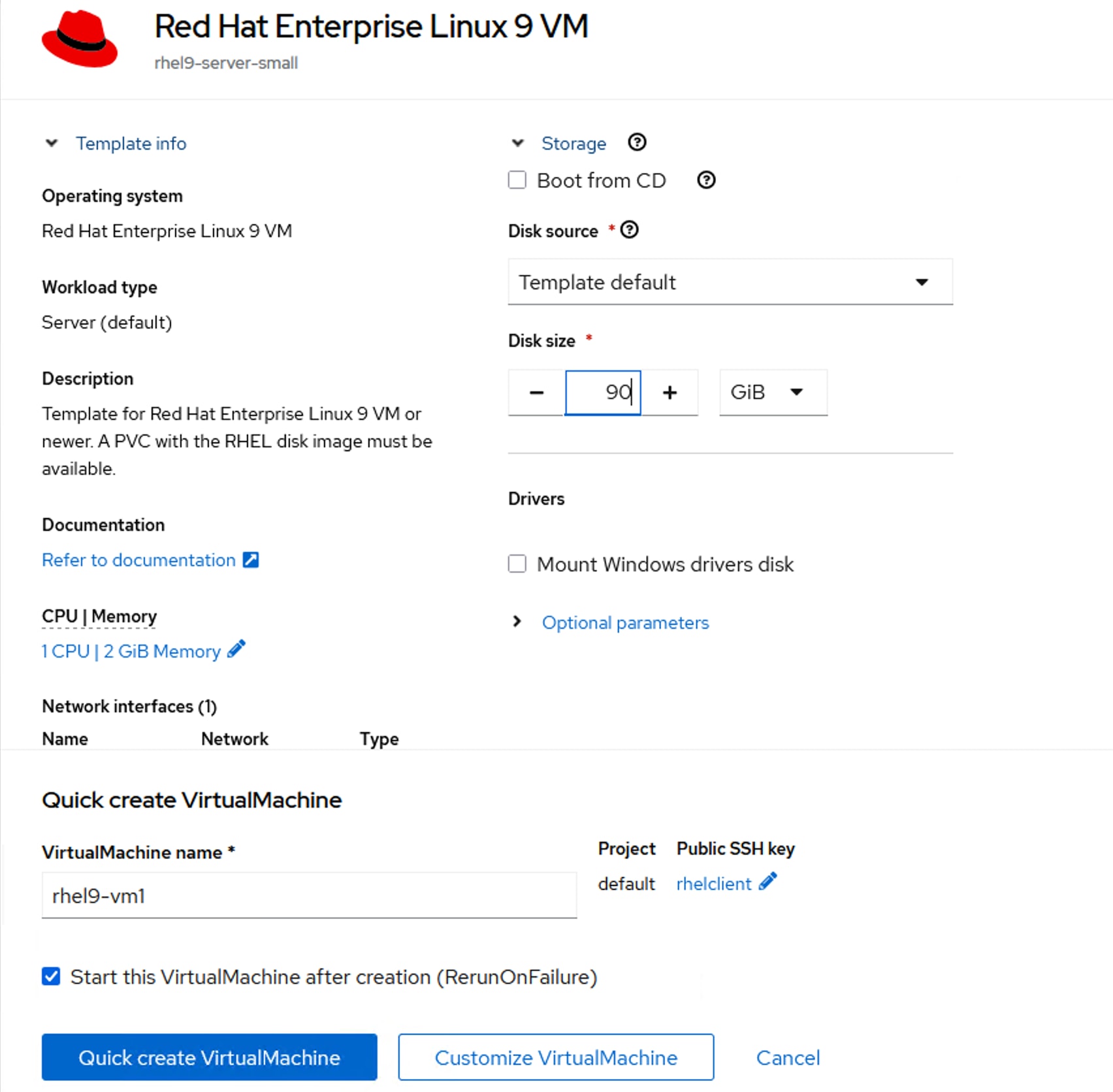
Step 10. Create secret and BareMetalHost objects in openshift-machine-api namespace by executing the following manifest (add-host-bm-x215-3-amdn8.yaml). See Table 21 for MAC addresses and OOB IP of the newly added node.
cat add-host-bm-x215-3-amdn8.yaml
apiVersion: v1
kind: Secret
metadata:
name: ocp-amdn8-bmc-secret
namespace: openshift-machine-api
type: Opaque
data:
username: aXBtaXVzZXIK
password: SDFnaFYwbHQK
---
apiVersion: metal3.io/v1alpha1
kind: BareMetalHost
metadata:
name: amdn8.fs-ocp.flashstack.local
namespace: openshift-machine-api
spec:
online: True
bootMACAddress: 00:25:B5:A3:0A:23
bmc:
address: redfish://10.106.0.41/redfish/v1/Systems/FCH283473D8
credentialsName: ocp-amdn8-bmc-secret
disableCertificateVerification: True
customDeploy:
method: install_coreos
externallyProvisioned: true
Note: The username and password shown in the above file are base64 encoded values.
Note: In this case, redfish connection is used for connecting to the server. 00:25:B5:A3:0A:23 is the MAC address of eno5 interface, 10.106.0.41 is the OOB management IP and FCH283473D8 is the serial number of the newly added worker node. These values are updated in Table 21. If you would like to use IPMI over LAN instead of redfish, just put the server’s out of band management IP for the bmc address field.
Step 11. Apply the bare metal configure for the newly added node.
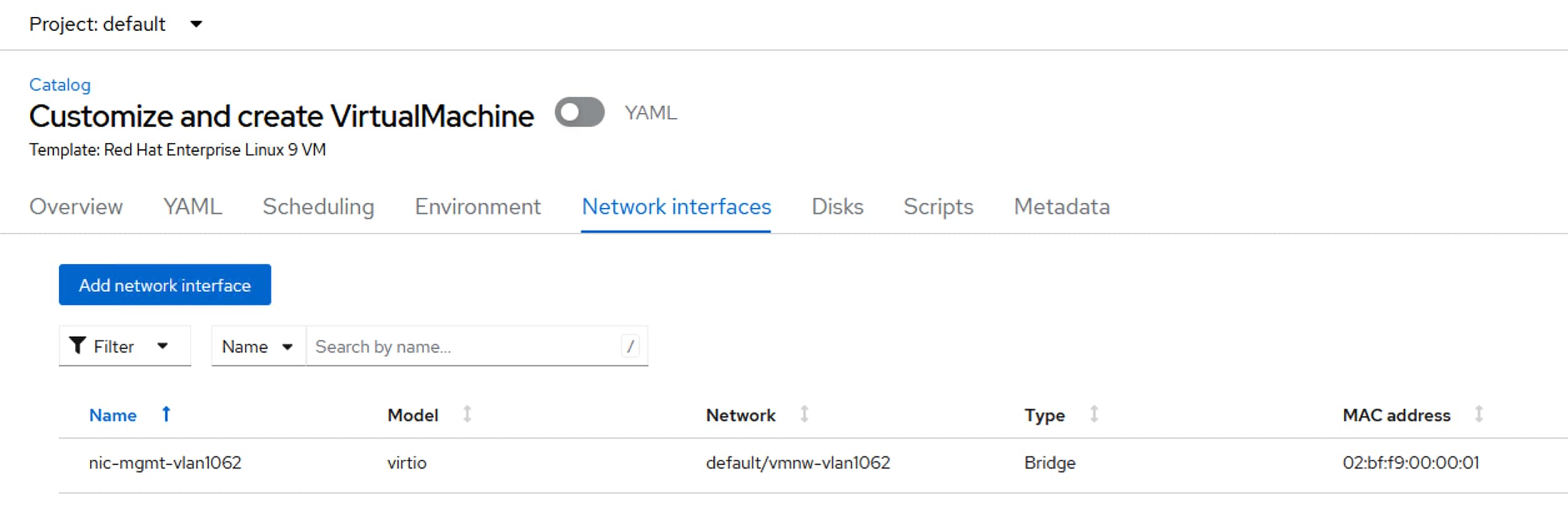
A new entry will be created for the newly added worker node under Compute > Bare Metal Hosts.
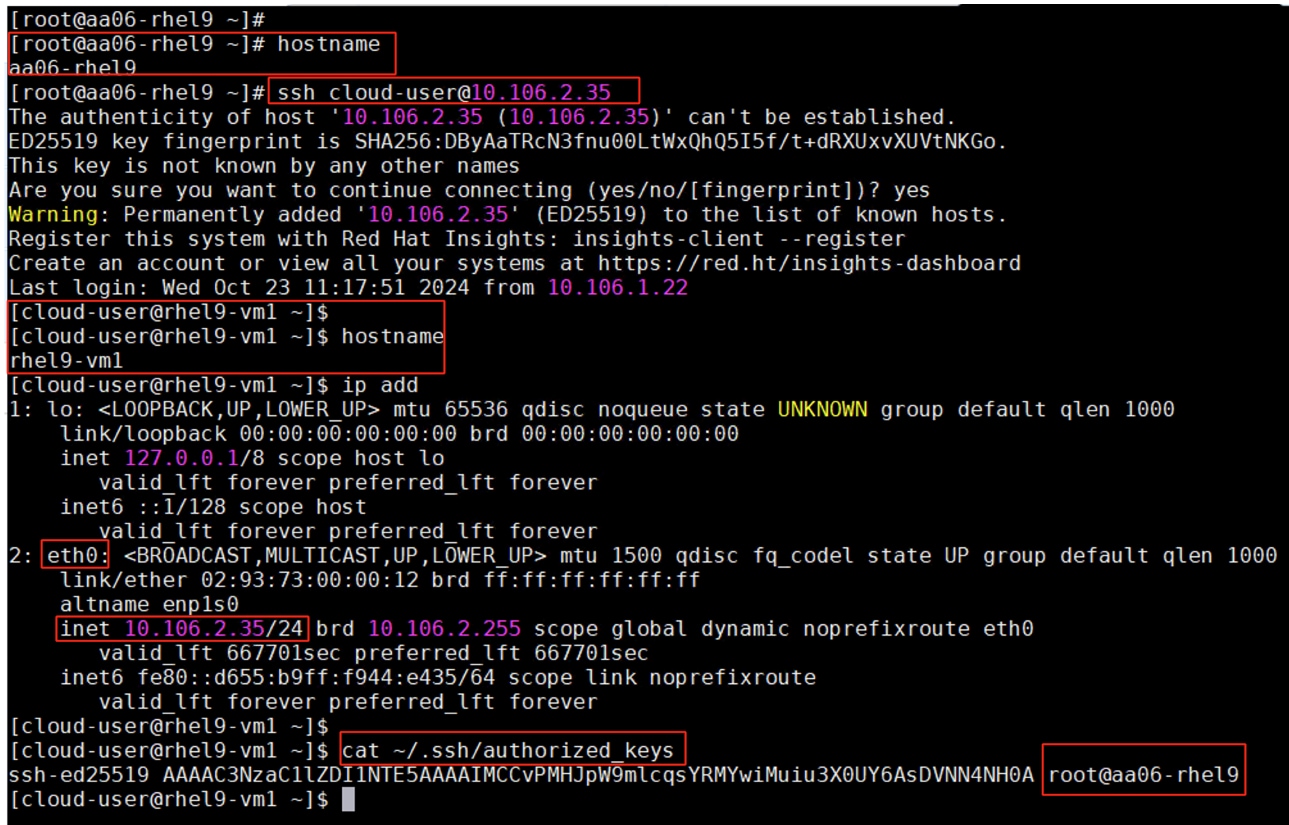
Note: The node field is not yet populated for this bare metal host since it is not yet logically linked to any OpenShift Machine.
Step 12. Increase the worker machineset count by one since you are adding one machine to the existing cluster. Go to Compute > MachineSets. Click the ellipses of worker-0 machineset and select Edit Machine Count and increase the count by 1. Click Save.
A new worker node will be provisioned to match to the worker new machine count. It is under the provisioning state until the node is logically mapped to the Bare Metal Host.
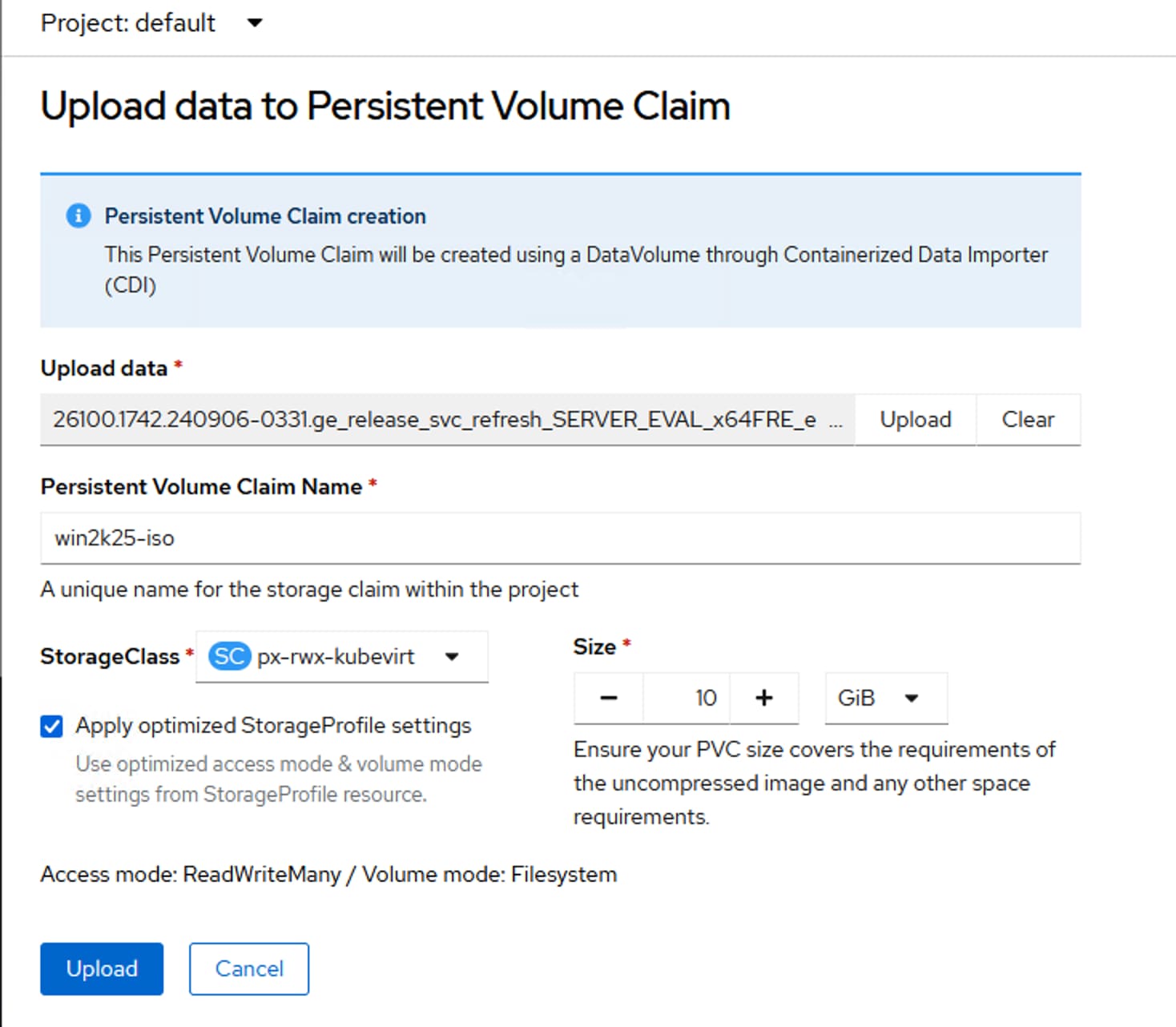
Procedure 2. Link the Machine and Bare Metal Host, Node and Bare Metal Host
Step 1. To logically link Bare Metal Host to Machine, obtain the name of the newly created machine from its manifest file or by running oc get machine -n openshift-machine-api:
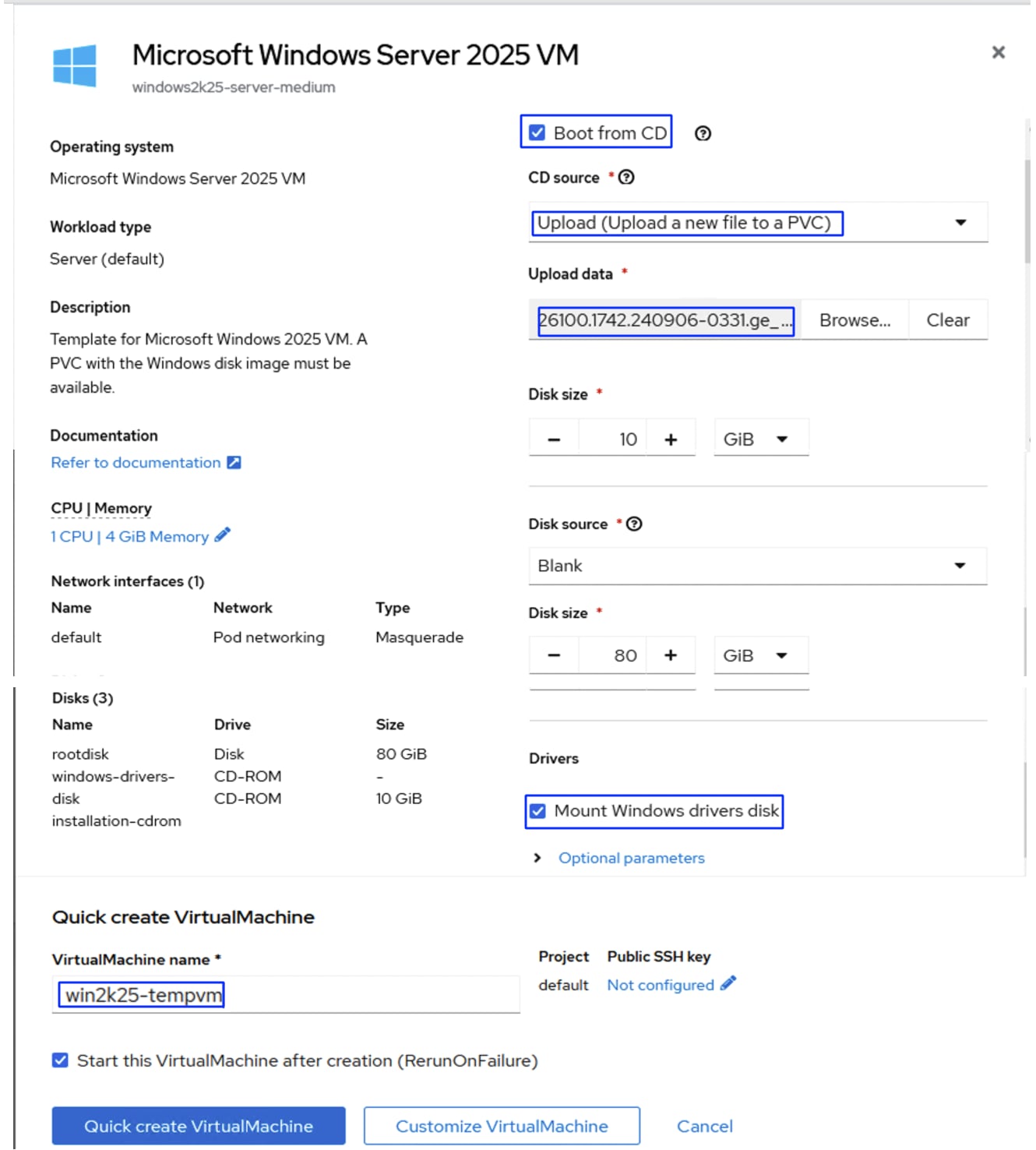
Step 2. Update the machine name in the Bare Metal Host’s manifest file under spec. consumerRef as shown below. Save the Yaml and reload:
consumerRef:
apiVersion: machine.openshift.io/v1beta1
kind: Machine
name: fs-ocp-rsf7z-worker-0-92mpw
namespace: openshift-machine-api
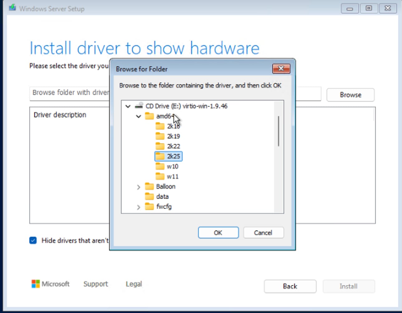
Step 3. The bare metal host providerID needs to be generated and updated in the newly added worker (amdn8.fs-ocp.flashstack.local). The providerID is a combination of the name and UUID of the Bare Metal Host and is shown below. These details can be gathered by running providerID: baremetalhost:///openshift-machine-api/<Bare Metal Host Name>/<Bare Metal Host UID>.
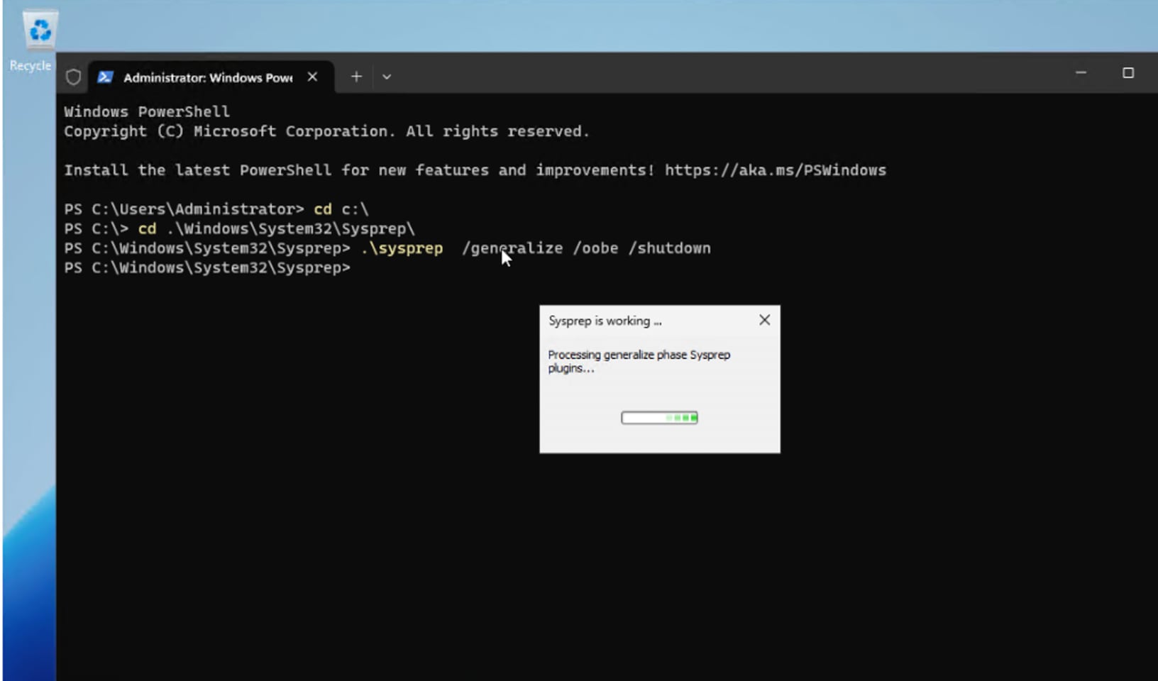
By using the provided information, the providerID for of the newly added Bare Metal Host is built as providerID: ‘baremetalhost:///openshift-machine-api/amdn8.fs-ocp.flashstack.local/1091e690-3735-49e7-bdce-a2a29f39559d’.
Step 4. Copy the providerID of the Bare Metal Host into the third node yaml manifest file under spec. as shown below:
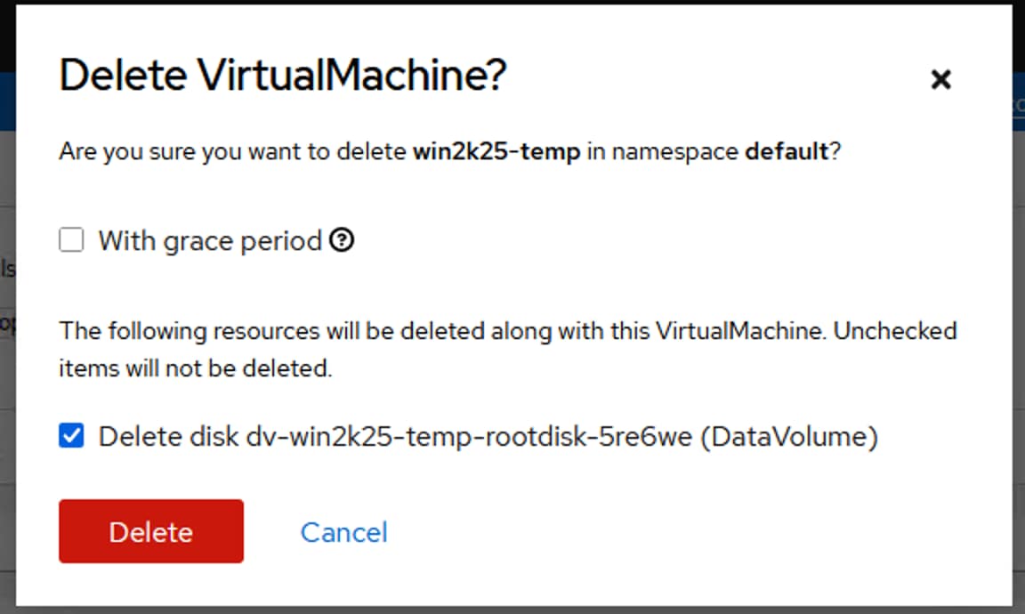
When the providerID of amdn8 is updated, the node details are automatically populated for the newly added Bare Metal Host as shown below:
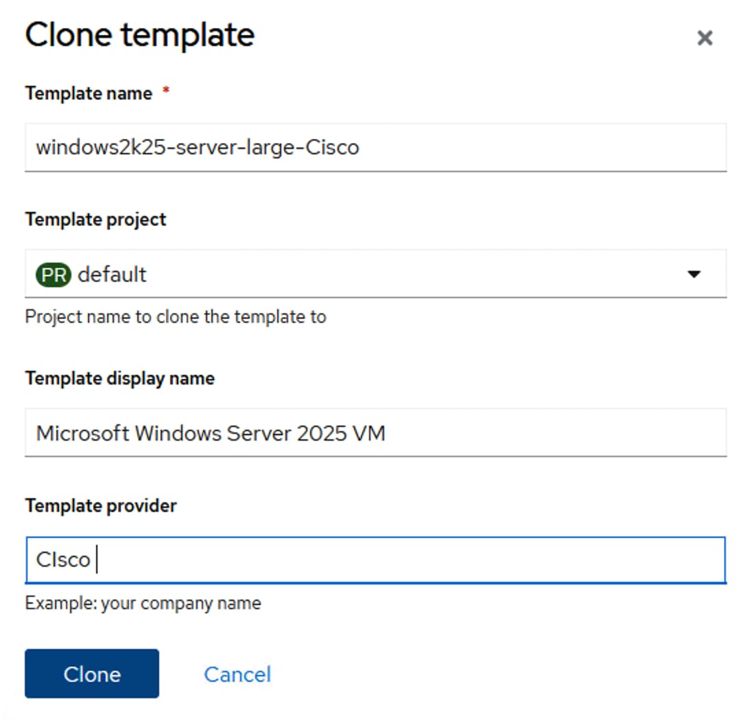
Step 5. After the node is added to the cluster, verify if daemonset pod of deployments Isovalent, Portworx and so on, are created automatically on the amdn8.fs-ocp.flashstack.local node as shown below:
oc get pods -n px -o wide | grep amdn8
portworx-api-vq697 2/2 Running 4 (2d12h ago) 2d12h 10.106.1.48 amdn8.fs-ocp.flashstack.local <none> <none>
px-cluster-bf76439c-a88e-4af3-9ccc-14c687ec1c31-rdtsc 1/1 Running 0 2d12h 10.106.1.48 amdn8.fs-ocp.flashstack.local <none> <none>
px-telemetry-phonehome-smprr 2/2 Running 4 18d 10.253.7.158 amdn8.fs-ocp.flashstack.local <none> <none>
oc get pods -n cilium -o wide | grep amdn8
cilium-66bks 1/1 Running 5 24d 10.106.1.48 amdn8.fs-ocp.flashstack.local <none> <none>
cilium-envoy-zl2xq 1/1 Running 5 24d 10.106.1.48 amdn8.fs-ocp.flashstack.local <none> <none
OpenShift Virtualization
This chapter contains the following:
● OpenShift Virtualization Operator
● Post Installation Configuration
● Create OpenShift Virtual Machines
● Migrate Virtual Machines from VMware vSphere Cluster to OpenShift Virtualization
Red Hat OpenShift Virtualization, an included feature of Red Hat OpenShift, provides a modern platform for organizations to run and deploy their new and existing virtual machine (VM) workloads. The solution allows for easy migration and management of traditional virtual machines onto a trusted, consistent, and comprehensive hybrid cloud application platform.
OpenShift Virtualization is an operator included with any OpenShift subscription. It enables infrastructure architects to create and add virtualized applications to their projects from OperatorHub in the same way they would for a containerized application.
Existing virtual machines can be migrated from other platforms onto the OpenShift application platform through the use of free, intuitive migration tools. The resulting VMs will run alongside containers on the same Red Hat OpenShift nodes.
The following sections and procedures provide detailed steps to create custom network policies for creating management and iSCSI networks for virtual machines to use, steps to deploy Red Hat virtual machines using pre-defined templates, steps to create custom Windows Server template and create windows virtual machine from this custom template.
OpenShift Virtualization Operator
This section provides the procedures necessary for the OpenShift Virtualization Operator.
Procedure 1. Deploy OpenShift Virtualization Operator
Step 1. If the Red Hat OpenShift Virtualization is not deployed, go to Operators > OperatorHub. Type virtualization in the All Items checkbox. From the available list, select the OpenShift Virtualization tile with Red Hat source label. Click Install to install OpenShift Virtualization with default settings.
Note: For OpenShift Virtualization operator, ensure that the Operator recommended namespace option is selected. This installs the Operator in the mandatory openshift-cnv namespace, which is automatically created if it does not exist
Step 2. When the operator is installed successfully, go to Operators > Installed Operators and type virtualization under the Name checkbox and verify that operator is installed successfully.
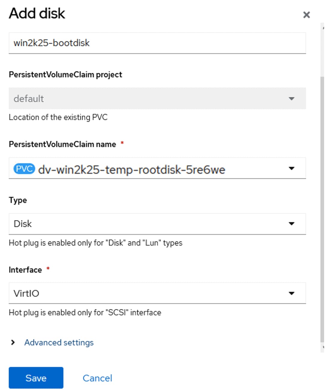
Post Installation Configuration
The procedures in this section are typically performed after OpenShift Virtualization is installed. You can configure the components that are relevant for your environment:
● Node placement rules for OpenShift Virtualization Operators, workloads, and controllers: The default scheduling for virtual machines (VMs) on bare metal nodes is appropriate. Optionally, you can specify the nodes where you want to deploy OpenShift Virtualization Operators, workloads, and controllers by configuring node placement rules. For detailed options on VM scheduling and placement options, see: https://docs.redhat.com/en/documentation/openshift_container_platform/4.18/html/virtualization/postinstallation-configuration#virt-node-placement-virt-components.
● Storage Configuration: Storage profile must be configured for OpenShift virtualization. A storage profile provides recommended settings based on the associated storage class. When the Portworx Enterprise is deployed on the OpenShift Cluster, it deploys several storage classes with different settings for different use-cases. OpenShift Virtualization automatically creates a storage profile with the recommended storage settings based on the associated storage class. There is no need for additional configuration.
● A Default Storage Class must be configured for the OpenShift Cluster. Otherwise, the cluster cannot receive automated boot source updates. To configure an existing storage class (created by Portworx) as Default Storage Class run the following command:
kubectl patch storageclass <StorageClassName> -p '{"metadata": {"annotations":{"storageclass.kubernetes.io/is-default-class":"true"}}}'
● Network configuration: By default, OpenShift Virtualization is installed with a single, internal pod network. After you install OpenShift Virtualization, you can install networking Operators and configure additional networks. The following sections provides more details on network configurations validated in this solution.
In this solution, the NMState operator and Multus CRDs are used for connecting the virtual machines to the secondary networks in the Red Hat OpenShift cluster.
NMState NodeNetworkConfigurationPolicies are already configured in Procedure 4. Install NMState Operator. The following NodeAttachmentDefinitions (NAD) are created for attaching the VMs to secondary networks.
Table 22. Node Attachment Definitions
| NAD Name |
Network |
NNCP used |
VLAN |
Purpose |
| vmnw-vlan1062 |
10.106.2.0/24 |
Bridge-vmgmt-nncp |
1062 (native) |
VMs management traffic over VLAN 1062 |
| vmnw-vlan1063 |
10.106.3.0/24 |
Bridge-vmgmt-nncp |
1063 |
VMs management traffic over VLAN 1063 |
| iscsi-vm-a-nad |
192.168.51.0/24 |
iscsi-vm-a-nncp |
3010(Native) |
In-Guest iSCSI traffic over Fabric-A fabric |
| iscsi-vm-b-nad |
192.168.52.0/24 |
iscsi-vm-b-nncp |
3020(Native) |
In-Guest iSCSI traffic over Fabric-B fabric |
The following yaml manifests are used for creating NAD definitions:
cat vm-mgmt-vlan1062-nad.yaml
apiVersion: k8s.cni.cncf.io/v1
kind: NetworkAttachmentDefinition
metadata:
name: vmnw-vlan1062
namespace: default
spec:
config: |-
{
"cniVersion": "0.3.1",
"name": "vmnw-vlan1062",
"type": "bridge",
"bridge": "br-vm-network",
"ipam": {},
"macspoofchk": false,
"preserveDefaultVlan": false
##"vlan": 1062. ##1062 is set as Native vlan. No need of mention it here.
}
cat vm-mgmt-vlan1063-nad.yaml
apiVersion: k8s.cni.cncf.io/v1
kind: NetworkAttachmentDefinition
metadata:
name: vmnw-vlan1063
namespace: default
spec:
config: |-
{
"cniVersion": "0.3.1",
"name": "vmnw-vlan1063",
"type": "bridge",
"bridge": "br-vm-network",
"ipam": {},
"macspoofchk": false,
"preserveDefaultVlan": false,
"vlan": 1063. ##1063 is not a native vlan
}
cat iscsi-vm-a-nad.yaml
apiVersion: k8s.cni.cncf.io/v1
kind: NetworkAttachmentDefinition
metadata:
annotations:
description: NAD for Guest iSCSI-A traffic
k8s.v1.cni.cncf.io/resourceName: bridge.network.kubevirt.io/iscsi-vm-a
name: iscsi-vm-a-nad
namespace: default
spec:
config: |-
{
"name": "iscsi-vm-a-nad",
"type": "bridge",
"bridge": "iscsi-vm-a",
"mtu": 9000,
"macspoofchk": false,
"preserveDefaultVlan": false
}
cat iscsi-vm-b-nad.yaml
apiVersion: k8s.cni.cncf.io/v1
kind: NetworkAttachmentDefinition
metadata:
annotations:
description: NAD for Guest iSCSI-B traffic
k8s.v1.cni.cncf.io/resourceName: bridge.network.kubevirt.io/iscsi-vm-b
name: iscsi-vm-b-nad
namespace: default
spec:
config: |-
{
"name": "iscsi-vm-b-nad",
"type": "bridge",
"bridge": "iscsi-vm-b",
"mtu": 9000,
"macspoofchk": false,
"preserveDefaultVlan": false
}
## create the NADs
oc apply -f vm-mgmt-vlan1062-nad.yaml
oc apply -f vm-mgmt-vlan1063-nad.yaml
oc apply -f iscsi-vm-a-nad.yaml
oc apply -f iscsi-vm-b-nad.yaml
The following scripts shows the NADs created for secondary VM networks:
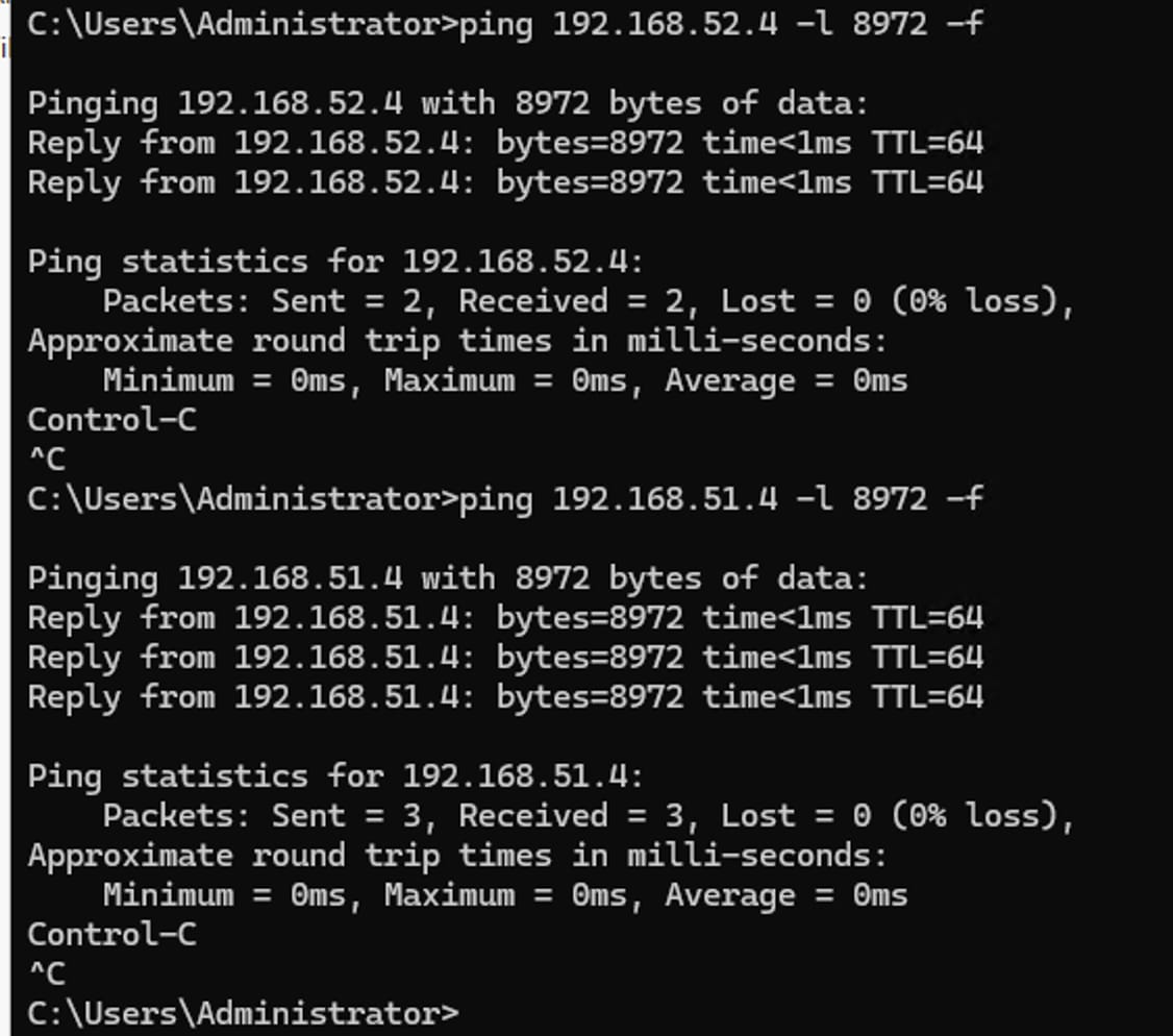
Create OpenShift Virtual Machines
This section explains the creation of linux and windows virtual machines. Before proceeding with virtual machines, ensure the following prerequisites are completed.
Note: Verify that you have Default storage classed configured. If the default storage class is not defined, the qcow2 boot images of various template VMs cannot be downloaded by OpenShift. Ensure Automatic Image Download option (Virtualization > Overview > Settings > General settings) is enabled. When this option is enabled, all the boot images will be downloaded automatically, and virtual machine templates will be configured with boot images as shown below.

Note: Ensure the required NNCP and NAD definitions are created for the VMs to attach to the secondary networks.
Procedure 1. Create Linux Virtual Machine
Step 1. To create a VM, go to Virtualization > Virtual Machines > Create > From template. Select one of the templates which has the Source available label on it.
Step 2. Provide a name to the VM and change the Disk size to the required size. Click Customize Virtual Machine.
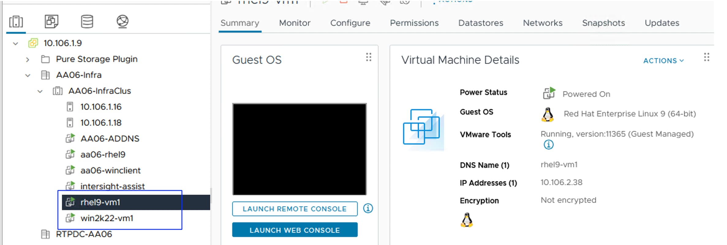
Step 3. From the Network Interface tab, remove the preconfigured Pod network interface and add new interface on vmnw-vlan1062 network as shown below:
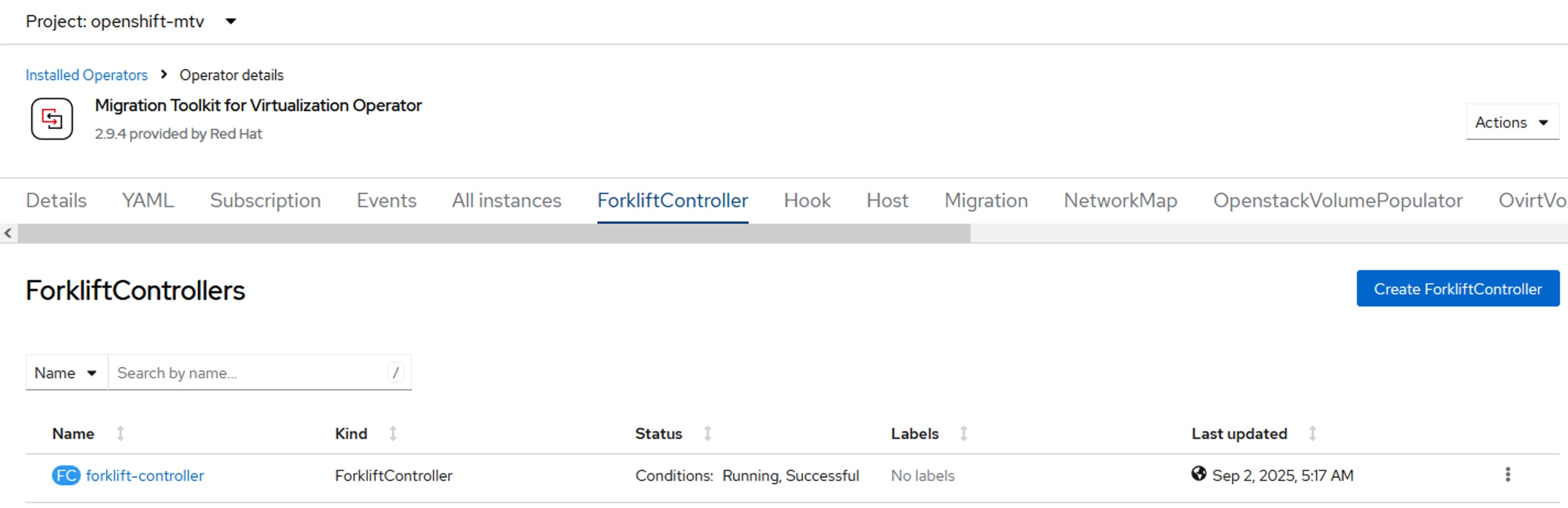
Step 4. From the Scripts tab, click the pen icon near Public SSH. Click Add New and upload the public key of your installer VM. Provide a name for the public key and check the box to use this key for all the VMs you create in future. Make a note of the default user name (cloud-user) and the default password. You can click the pen icon and change default user and password.
Step 5. Optionally, from the Overview tab, change the CPUs and memory resources to be allocated to the VM. Click Create Virtual Machine.
In a few seconds a new virtual machine will be provisioned. The interface of the VM will get a DHCP IP from vmnw-vlan1062 network and the VM can be accessed directly from rhel-installer VM (aa06-rhel9) using its public ssh key without using password as shown below:
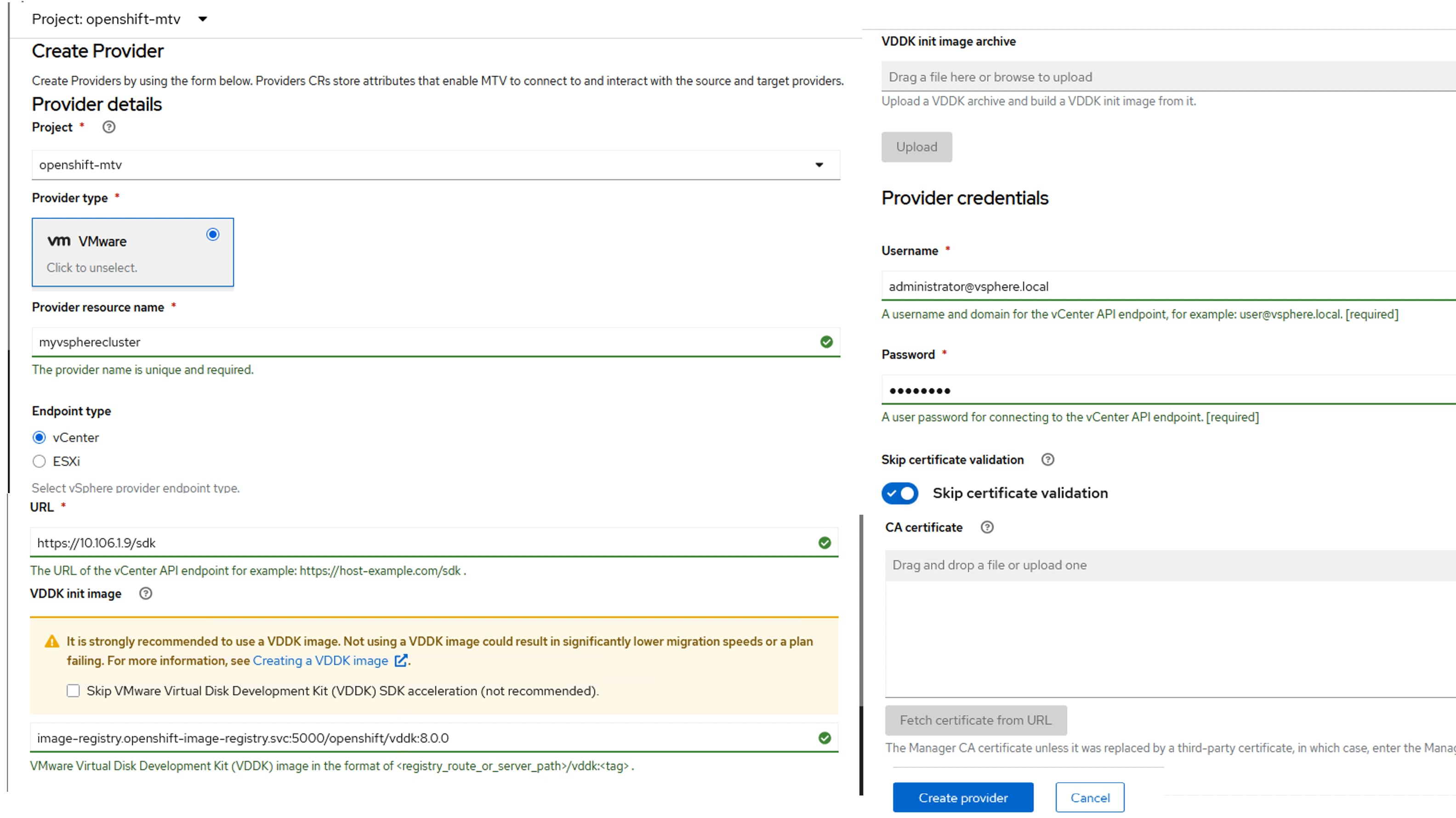
Procedure 2. Create Windows Template and provisioning Windows VMs from Template
Follow this procedure to create a temporary windows Server 2025 virtual machine using Windows Server ISO, then install and configure the VM with all the required software components. Use this VM to create sysprep image. Then use this sysprep image as gold image for all the future windows Server 2025 VMs. Before proceeding with VM creation, Download the Windows Server 2025 ISO from Microsoft website
Step 1. To create a new VM, go to Virtualization > Virtual Machines > Create > Using Template. Select Windows server 2025 (windows2k25-server-medium) template.
Step 2. From the Create VM window, check the box for Boot from CD and select Upload (upload a new file to PVC) option for CD source. Click Browse. The Upload data to PVC window opens. Provide a name to the PVC (win2k25-iso) and set the storage class to px-rwx-kubevirt and click Upload.
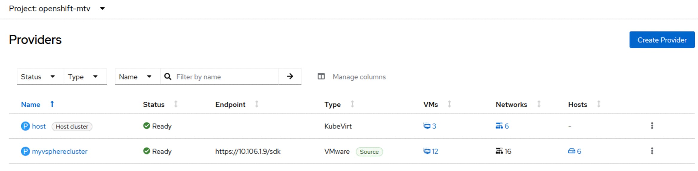
Step 3. Once the PVC is created, from the Create VM window, provide a name to the windows VM. (win2k25-tempvm) and to create a new VM, go to Virtualization > Virtual Machines > Create > Using Template. Select Windows server 2025 (windows2k25-server-medium) template.
Step 4. From the Create VM window, check the box for Boot from CD and select Upload (upload a new file to PVC) option for CD source. Set Blank for Disk Source and set 80G for the Disk size. Select Mount Windows Drivers disk. Click Customize VirtualMachine. This starts the uploading of the ISO to the PVC.
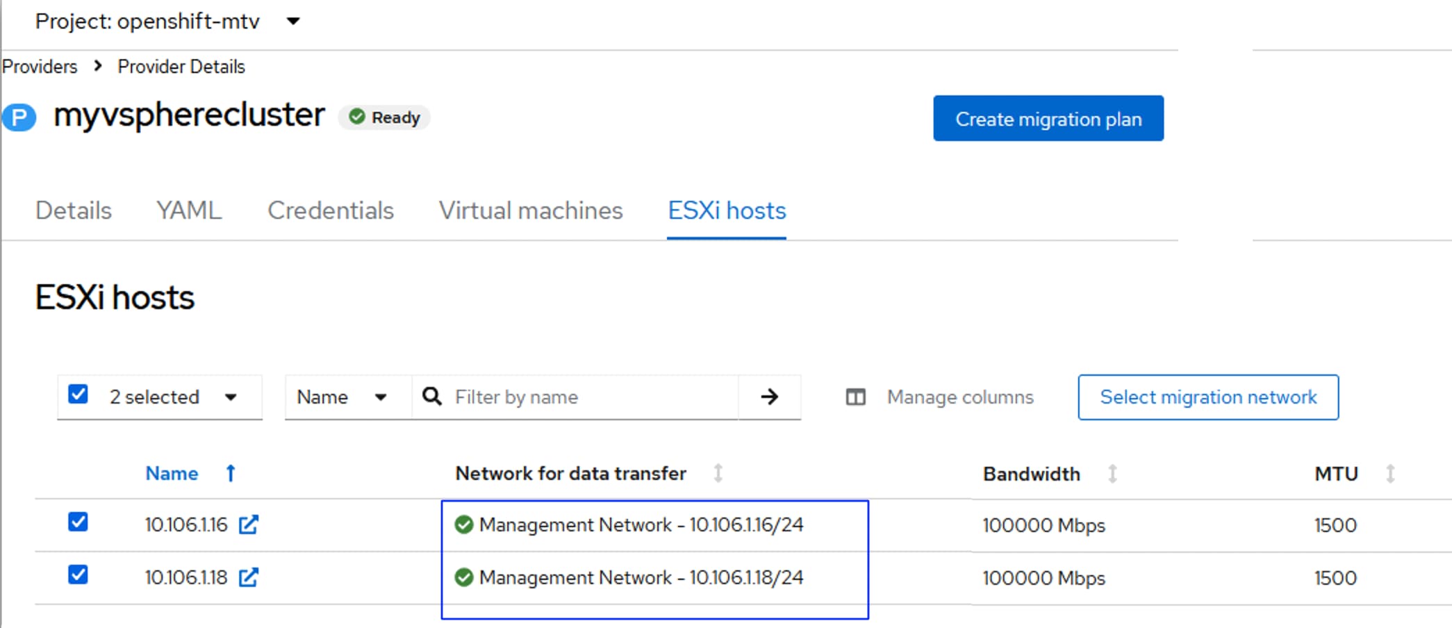
Step 5. Click the Disks tab. By editing the root disk, set the disk driver from SATA to Virtio and storage class to px-rwx-kubevirt. Click Create VM. When the VM is connected, connect to the VM console and press any key to start Windows Server 2025 installation. From the Windows Server setup window, select Install Windows Server and check the box and then click Next.
Step 6. From the Select location to install Windows Server window, click Load Driver link and select the folder E:\virtio-win-XX\amd64\2k25\.
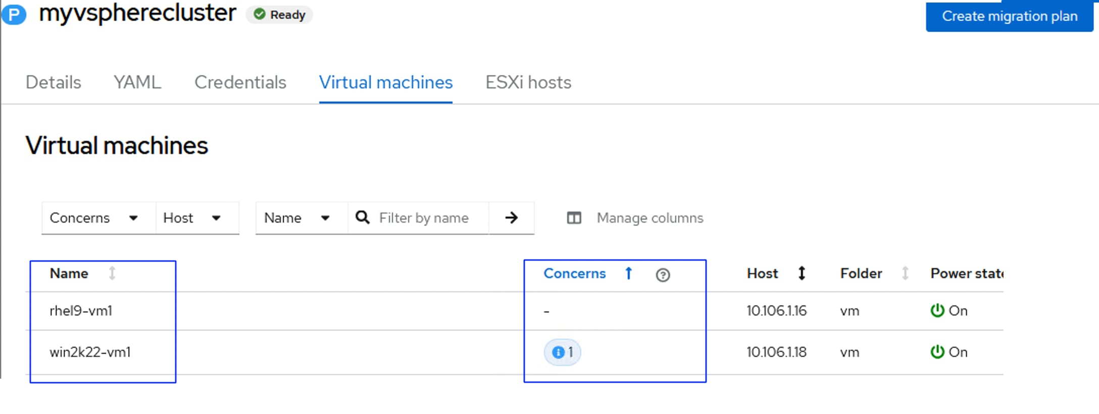
Step 7. Select Red Hat VirtIO SCSI controller driver and click Install. Once driver is installed successfully, the 80G volumes display for the OS installation. Select the volume, click Next and then click Next again. Once OS installed, provide Administrator password and then login to the Windows server 2025.
Step 8. When the Windows is installed successfully, go to E:\ disk and install the virtio driver by double-clicking the virtio-win-gt-x64.msi. Complete the drivers installation with default options.
Step 9. When the drivers are installed, the network interfaces display and are assigned with a DHCP IP address. Turn off the firewalls temporarily to verify the VM can reach the outside services like AD/DNS. Enable Remote Desktop.
Note: Install and configure the required software, roles, features etc before converting this image as template.
Step 10. Convert this temporary VM into a sysprep image by executing the sysprep command as shown below. When sysprep is completed, the VM tries to restart. Before it restarts, stop the VM from OpenShift console.
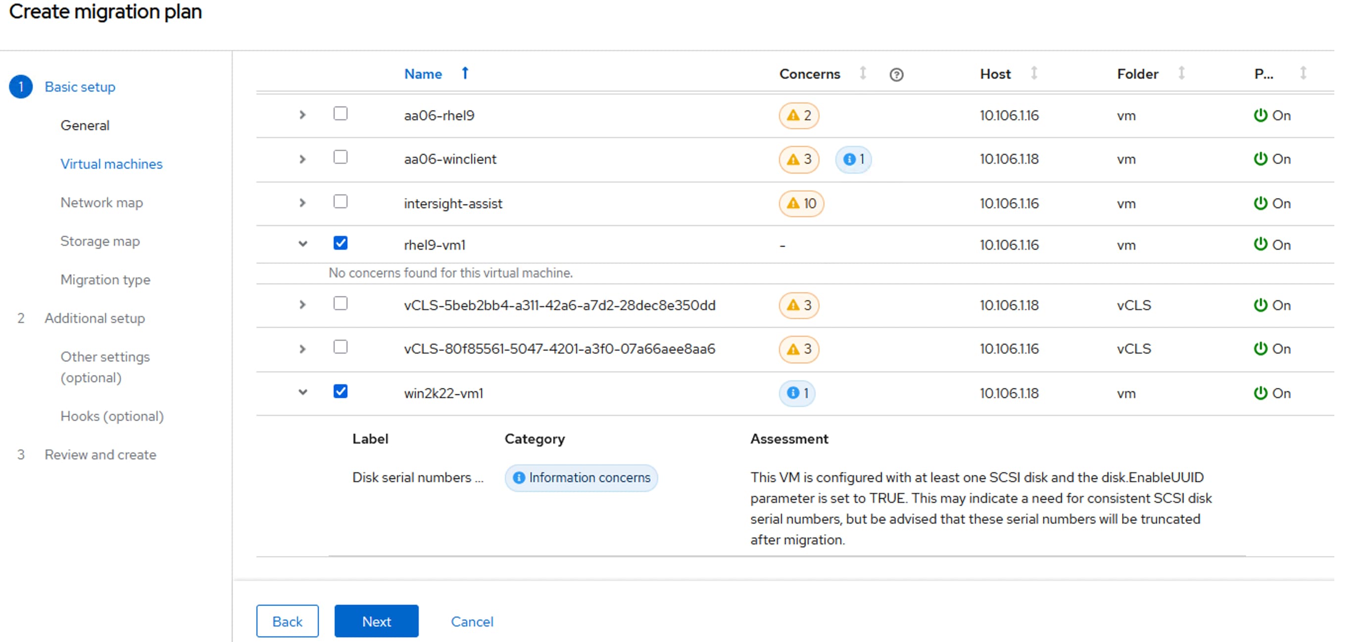
Step 11. Delete this temporary VM. While deleting the VM, ensure you DO NOT delete the root disk of this VM by unchecking the checkbox as shown below:
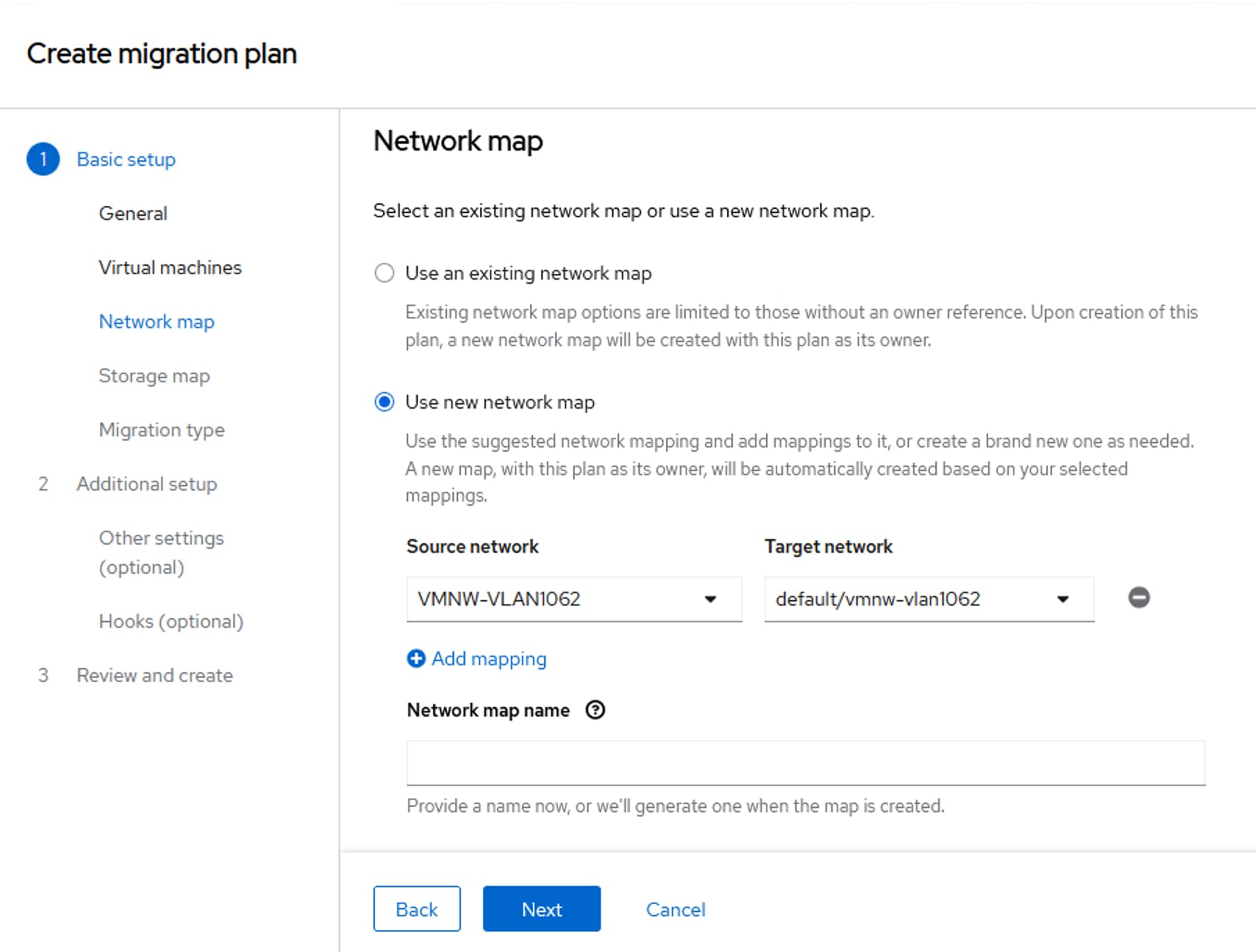
Note: This data volume has the Windows Server 2025 boot image of and can be used as the boot image for Windows Server Template.
Step 12. Create a new template by cloning the existing windows2k25-server-large template. Click the ellipses and select Clone. Provide a name to the new template (windows2k25-server-large-Cisco) and click Clone.
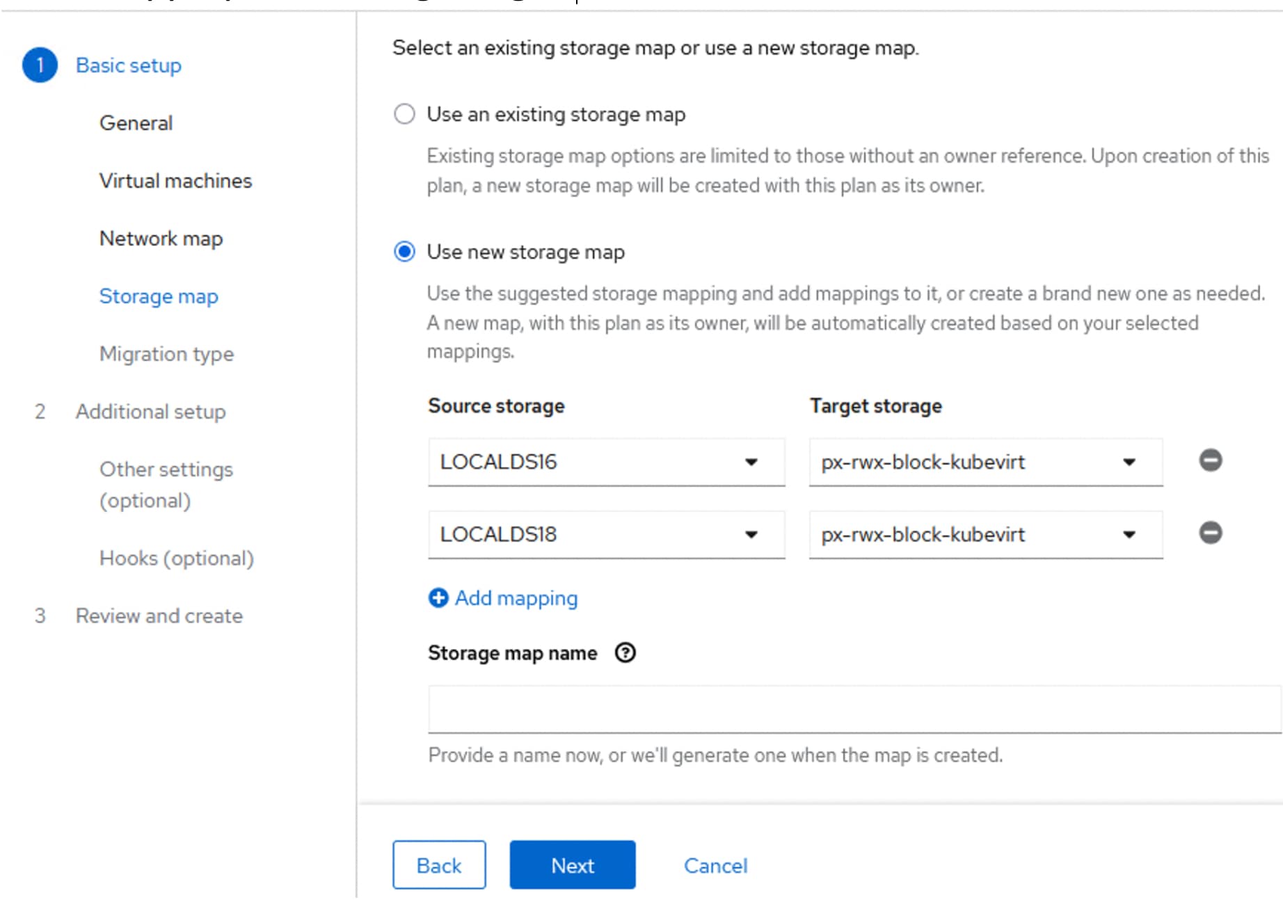
Step 13. Click the newly created template and then go to the Disks tab. Click Add Disk > Clone Volume to add a new disk. Select the template. Edit this newly created windows2k25-template by clicking Edit. Select the PVC that has the Windows Server 2025 sysprep image previously created. Click Save.
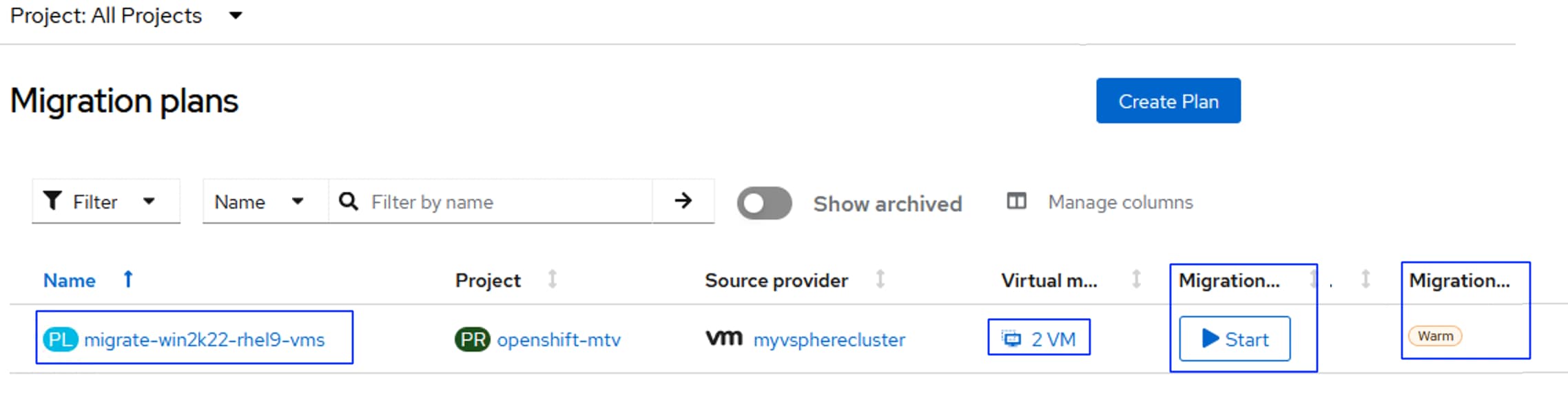
Step 14. Delete the existing root disk. The newly added disk automatically sets as new root disk.
Step 15. Go to Network Interfaces, add two additional network interfaces from iscsi-vm-a-nad and iscsi-vm-b-nad.
Note: This template is customized to boot from the sysprep image and configured with a total of three interfaces. One for management and two for iSCSI traffic.
Step 16. Create a fresh Windows Server 2025 virtual machine using the template created in the previous steps. Go to Virtualization > VirtualMachines > Create > From template. Click User templates. Select the new windows2k25-server-large-Cisco.
Step 17. Provide a name for the VM and click Quick Create VirtualMachine. Since the template is pre-configured with everything according to our requirements, nothing has to be changed to create the virtual machine. The VMs displays in seconds.
Step 18. When the VM is fully provisioned, verify all three interfaces get corresponding DHCP IP addresses and are able to reach the FlashArray//XL170 target IP addresses with larger packet sizes as shown below:
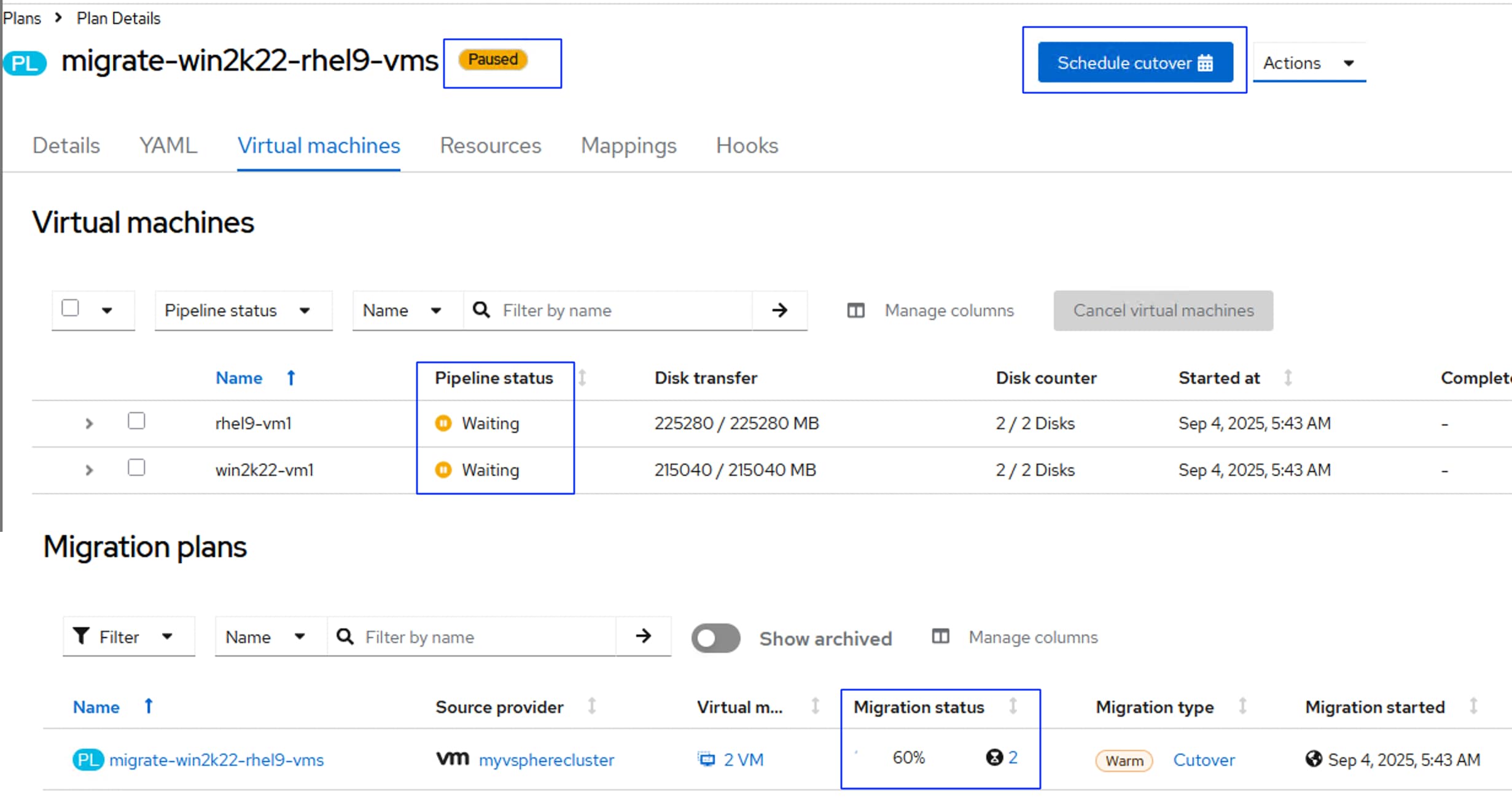
Step 19. Since the storage target IP addresses are reachable from the VM, the VM can be connected to the FlashArray volumes directly by configuring the in-guest iscsi initiator.
Step 20. To migrate the VM from one to other, click ellipses and select Migrate. The VMs will be migrated to a different worker node.
Migrate Virtual Machines from VMware vSphere Cluster to OpenShift Virtualization
The Migration Toolkit for Virtualization (MTV) is an operator-based functionality that enables us to migrate virtual machines at scale to Red Hat OpenShift Virtualization. MTV supports migration of virtual machines from VMware vSphere, Red Hat Virtualization, OpenStack, OVA and OpenShift Virtualization source providers to OpenShift Virtualization. VMware vSphere VMs were migrated to OpenShift. RHEL and Windows VMs were successfully imported and all migrated VMs were brought into OpenShift with both virtio network interfaces and virtio disk controllers.
The following are some of the vSphere prerequisites to be met before planning for migration of virtual machines from vSphere environments:
● VMware vSphere version must be compatible with OpenShift virtualization. At a minimum, vSphere 6.5 or later is compatible with OpenShift Virtualization 4.14 or later. For more details on compatibility, go to: https://docs.redhat.com/en/documentation/migration_toolkit_for_virtualization/2.9/html-single/installing_and_using_the_migration_toolkit_for_virtualization/index#compatibility-guidelines_mtv
● Not all guest operating systems migration is supported. Only the specific Guest Operating Systems can be migrated to OpenShift Virtualization. See the list of guest operating systems supported by OpenShift Virtualization here: https://access.redhat.com/articles/1351473?extIdCarryOver=true&sc_cid=RHCTG0250000454097
● The guest OS must be supported by virt-v2v utility to convert them into OpenShift virtualization compatible images as listed here: https://access.redhat.com/articles/1351473
● You must have a user with at least the minimal set of VMware privileges. Required privileges listed here: https://docs.redhat.com/en/documentation/migration_toolkit_for_virtualization/2.9/html-single/installing_and_using_the_migration_toolkit_for_virtualization/index#vmware-prerequisites_mtv
● The Secure boot option must be disabled on the VMs.
● For a warm migration, changed block tracking (CBT) must be enabled on the VMs and on the VM disks. Here are the steps for enabling CBT on the VMs running on vSphere cluster: https://knowledge.broadcom.com/external/article/320557/changed-block-tracking-cbt-on-virtual-ma.html
● The MTV can use the VMware Virtual Disk Development Kit (VDDK) SDK to accelerate transferring virtual disks from VMware vSphere. Optionally, VDDK can be used for the faster migration. For this validation, VDDK is installed as detailed here: https://docs.redhat.com/en/documentation/migration_toolkit_for_virtualization/2.9/html-single/installing_and_using_the_migration_toolkit_for_virtualization/index#creating-vddk-image_mtv
The following image shows the VDDK image version 8.0.0 is available in the OpenShift local image registry. The full local image path to pull the VDDK image is Image-registry.openshift-image-registry:5000/openshift/vddk:8.0.0.
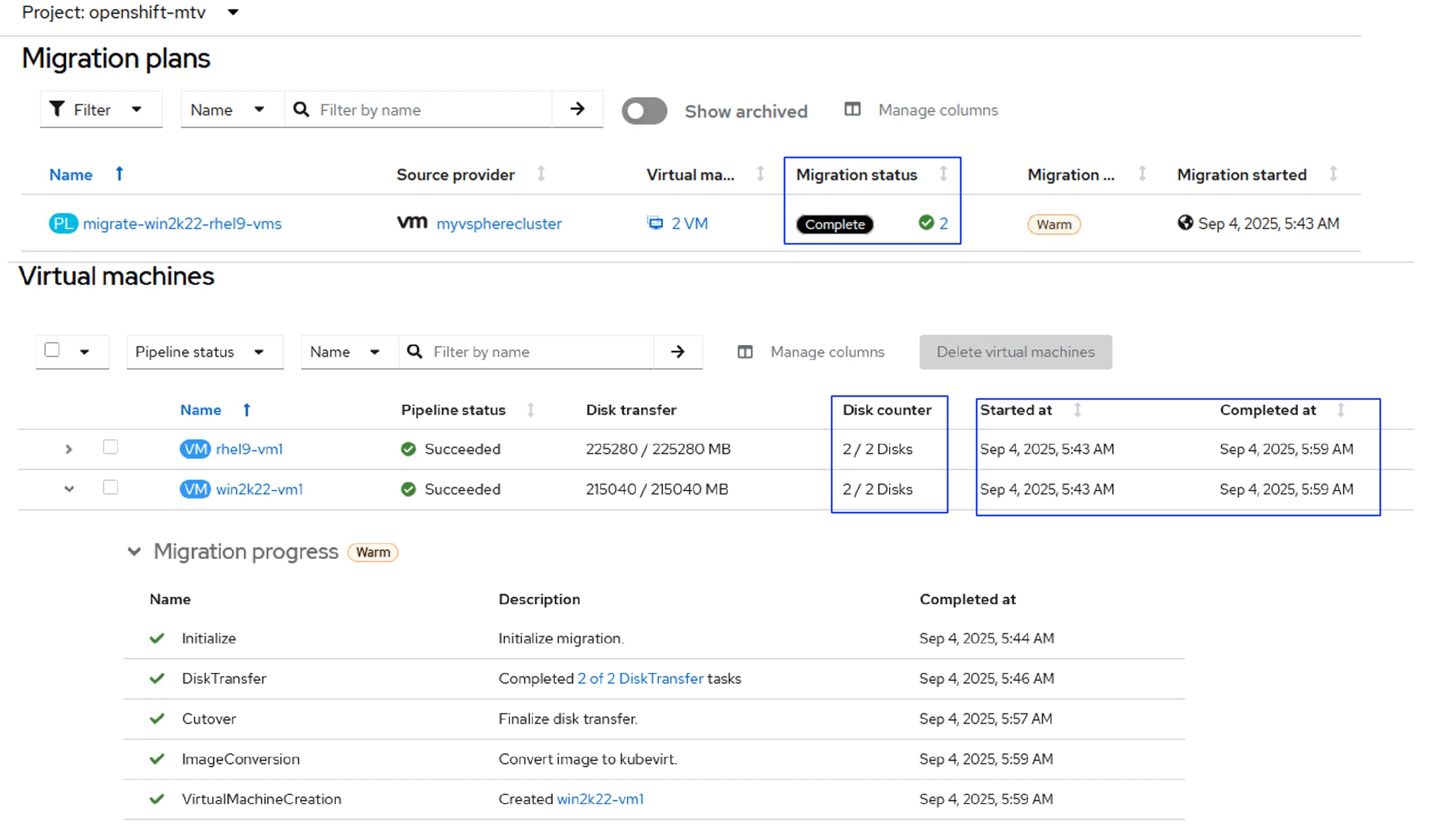
For more information on the MTV prerequisites, see: https://docs.redhat.com/en/documentation/migration_toolkit_for_virtualization/2.9/html-single/installing_and_using_the_migration_toolkit_for_virtualization/index#rhv-prerequisites_mtv
The virtual machines with guest-initiated storage connections, such as Internet Small Computer Systems Interface (iSCSI) connections or Network File System (NFS) mounts, are not handled by MTV and could require additional planning before or reconfiguration after the migration.
This section describes the migration of the following two VMs running on vSphere 8.0 cluster:
| VM Name |
Number of Disks |
VLAN/MAC/IP |
| rhel9-vm1 |
OS Disk: 120GiB Data Disk: 100GiB (mounted on /data directory) |
VLAN: 1062 MAC: 00:50:56:a5:50:44 IP: 10.106.2.38 |
| Win2k22-vm1 |
OS Disk: 90GiB Data Disk: 120G (E:\drive) |
VLAN: 1062 MAC: 00:50:56:a5:90:00 IP: 10.106.2.40 |
The following screenshot shows the vSphere cluster with above two VMs (rhe8-vm1 and win2k19-vm2) to be migrated to OpenShift cluster:
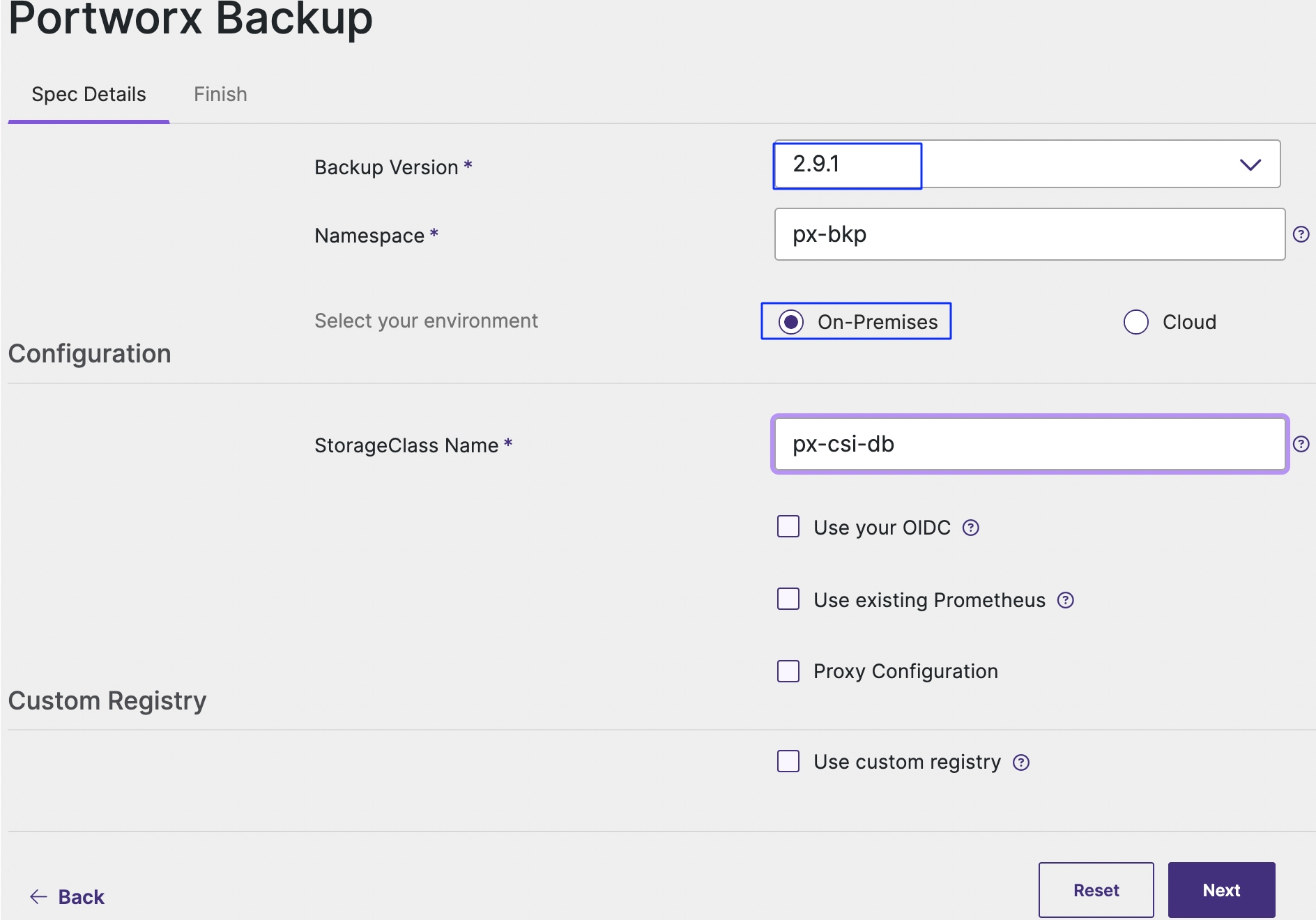
Procedure 3. Install the Migration Toolkit for Virtualization
Step 1. Install the MTV operator, go to Operators > OperatorHub, search for mtv, and select the Migration Toolkit for Virtualization operator and click Install. When the operator is installed successfully, click Create ForkliftController to install the ForkliftController. With the default option, complete the FortliftController installation. Refresh the browser to view the Migration tab on the console.
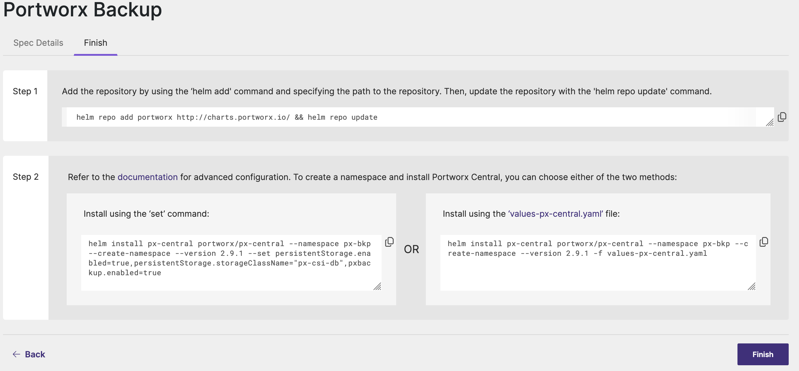
The actions to perform the migration of VMs from vSphere environment to OpenShift Virtualization are as follows:
● Identify the VMs on the vSphere environment and ensure the VMs are ready for migration by verifying that all the prerequisites are met
● Create Provider
● Create Migration Plan
● Execute the migration plan
Procedure 4. Migrate VMs from vSphere to OpenShift Virtualization
Step 1. To create vSphere Provider, go to Migration > Providers for Virtualization and click Create Provider. Select the required project name and select vm VMware. Provide a name to the provider, URL to the provider sdk in the format https://host-example.com/sdk, URL for VDDK, and credential details as shown below. Click Create Provider to create the vSphere cluster as provider.
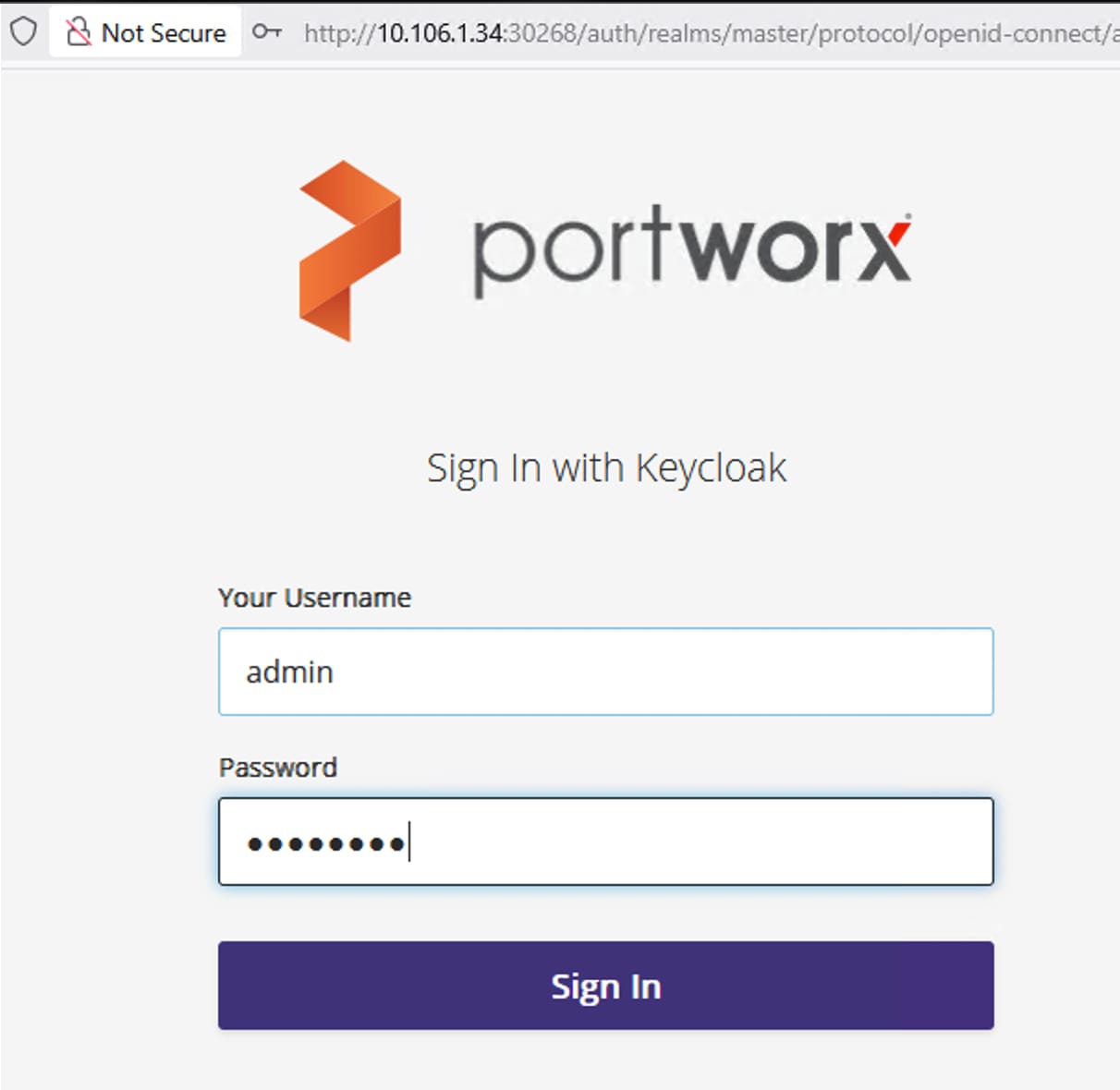
The following vSphere provider is created:
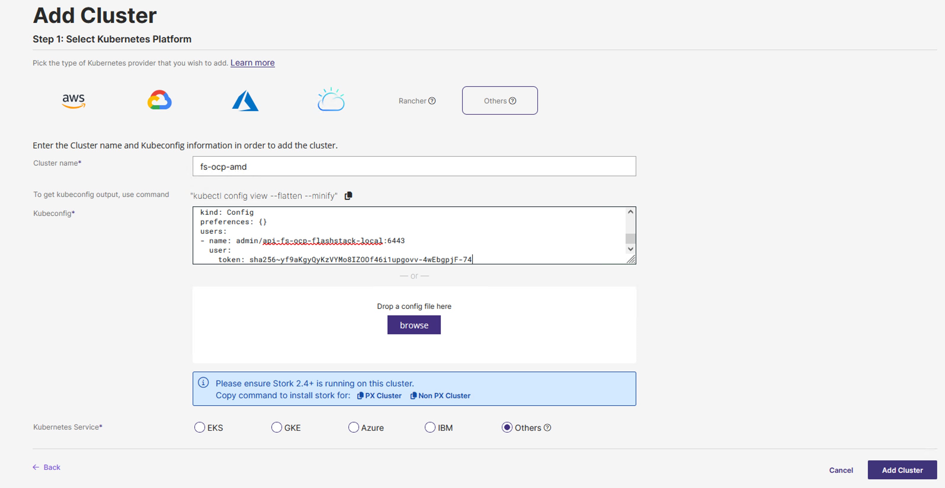
Step 2. Click the vSphere provider, then click ESXI Hosts, select the hosts that are currently owning the VMs and click Select Migration Network. Select the Management Network 10.106.1.X/24 and provide root credentials. Click Save.

Step 3. Click the Virtual machines tab and review the list of Warning concerns (yellow colored) reported for each source VM. You need to address each and concern and clear them.
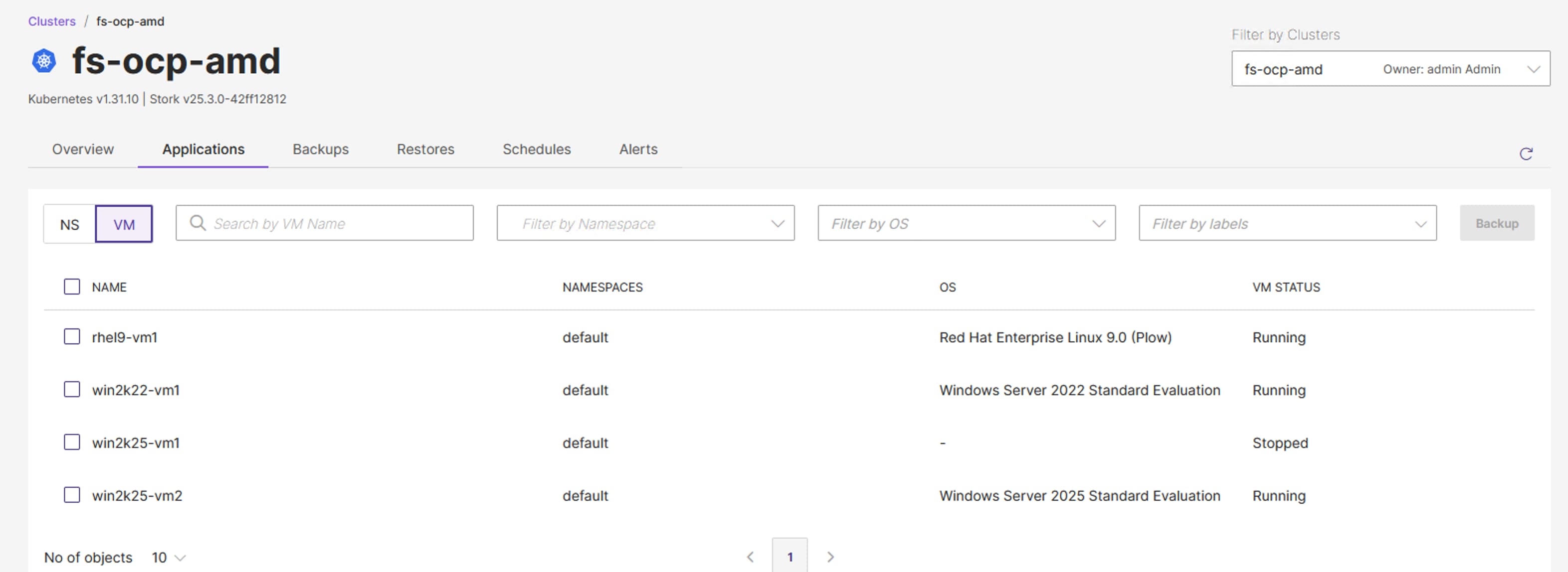
Procedure 5. Create Migration Plan
Step 1. Go to Migration > Plan for Virtualization and click Create Plan. Provide a name to the migration plan and select the project name. Select the vSphere provider previously created. Select the OpenShift cluster (host) as Target Provider and Target project as default. Click Next.
Step 2. Select the VMs rhel9-vm1 and win2k222-vm1 that need to be migrated to OpenShift. Click Next.
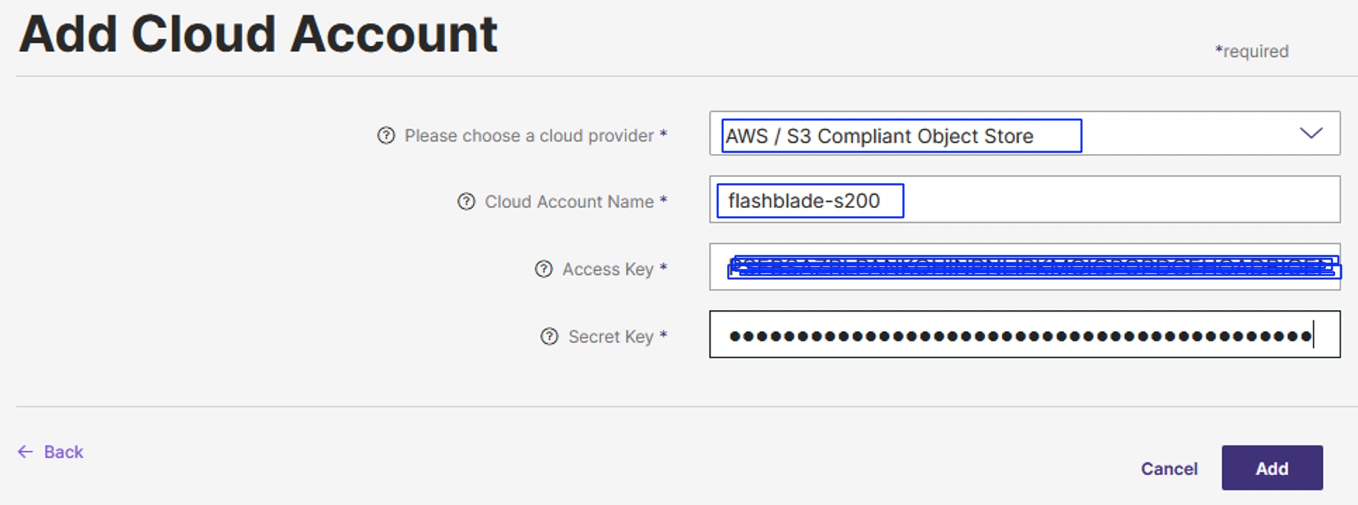
Step 3. From the Network Map tab, click Use New Network Map and select the appropriate source and target networks as shown below. Click Next.

Step 4. From the Storage Map tab, click Use New Storage Map and select the appropriate source and target networks as shown below. Click Next. Ensure to the storage class that support RWX option. Click Next.
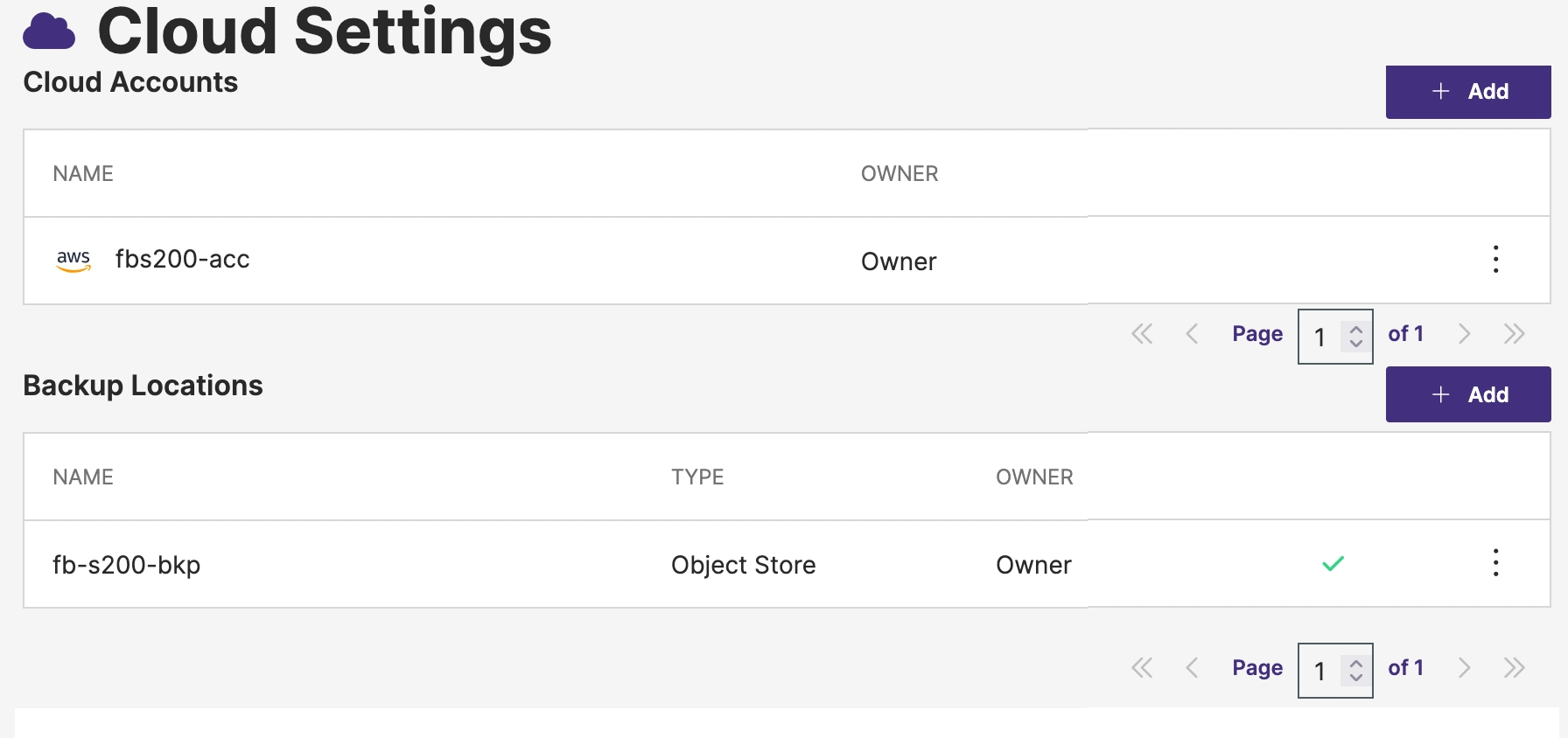
Step 5. Select the migration type. For this validation, warm migration is selected. Click Next.
Step 6. Optional: From the Additional Steps tab, select Perverse Static IPs and Migrate shared disks options.
Step 7. Review the migration plan and click Create Plan.
All the options in the migration plan will be validated, and the plan status will be set to Start when all the options are valid.
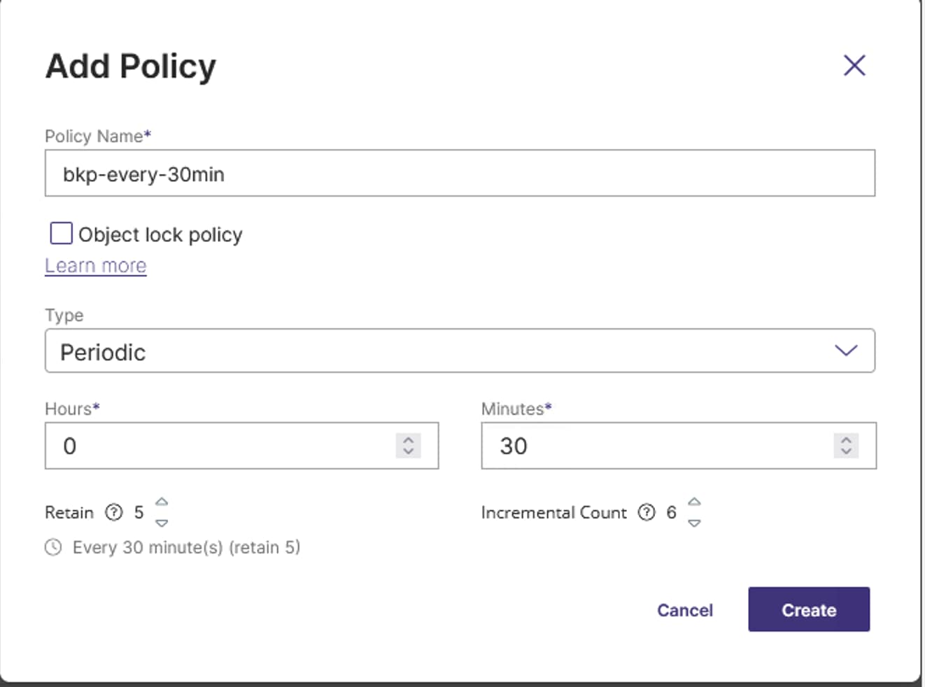
Step 8. Click Start to start the migration of VMs.
Note: If the warm migration is selected for the VM migration, when the migration plan reaches cutover stage, you need to schedule the cutover time to finalize the warm migration. Until then the migration plan will be paused.
Step 9. To schedule cutover time, click the migration plan > virtual machines. Click Schedule cutover located on the top right. Once you set the time for cutover, the migration plan will resume at the cutover you set.
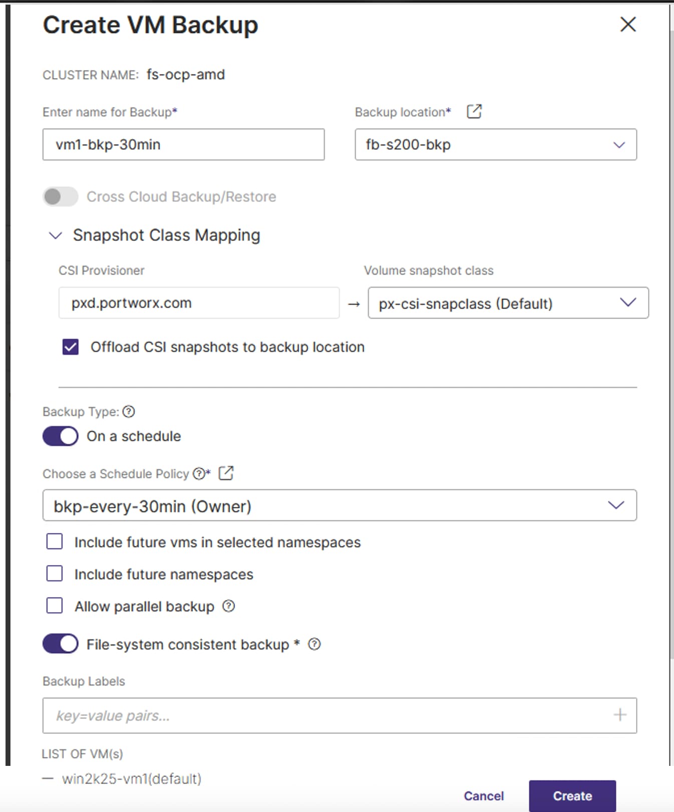
When the VMs migrated successfully to the OpenShift cluster the Migration status is complete:
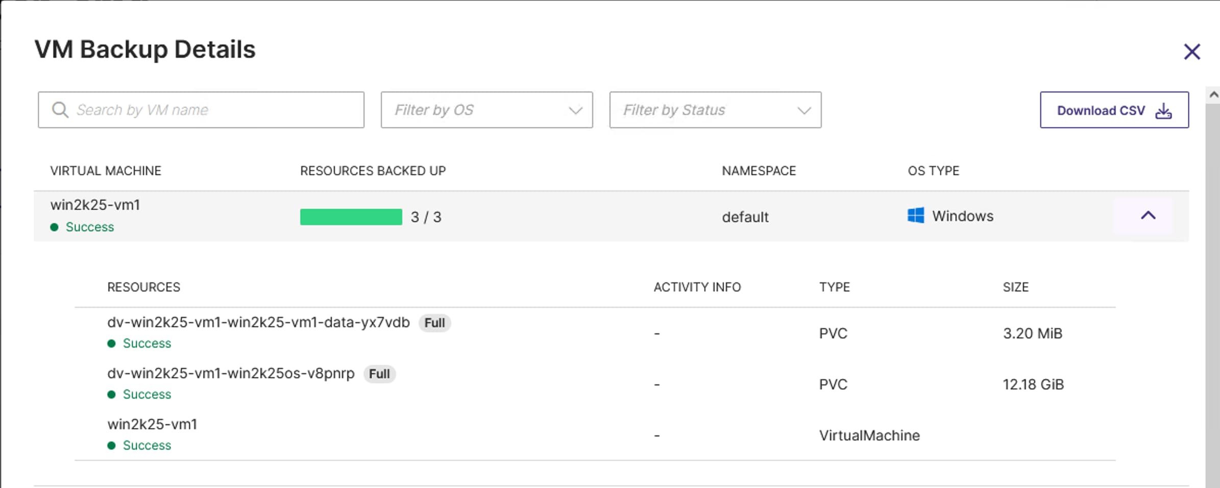
When the VMs are migrated to the OpenShift, ensure the agents are running inside the virtual machines, all the disks are mounted to the right folders, IP addresses and MAC addresses are retained.
Data Protection with Portworx Backup
This chapter contains the following:
● Backup and Restore Virtual Machines
The following prerequisites need to be met before proceeding with this PX-backup validation.
● PX-Backup can be installed on a dedicated Kubernetes cluster or on the application clusters where application workloads are running. For this validation, PX-Backup is installed on a dedicated OpenShift cluster (fs-ocp1.flashstack.local) installed on a different set of hardware. Later, this FlashStack AMD M8 based cluster (fs-ocp.flashstack.local) is registered as an application cluster for protecting the virtual machines and applications running on the cluster.
● Pure Storage FlashBlade//S200 should be reachable from both clusters. For this connectivity, network interface eno11 is used for carrying the backup/restore traffic with VLAN 3040 from clusters to the FlashBlade. Refer vNIC Template and vNICs section for more details on eno11 interface.
● Ensure User Accounts, users, Access policies, and buckets are already configured on FlashBlade. These details will be used while adding backup locations in PX-backup.
● Ensure that stork scheduler is installed on all the application clusters. For this validation, the stork component is automatically installed when Portworx Enterprise is installed on the clusters. For more details on stock requirement, refer: https://docs.portworx.com/portworx-backup-on-prem/install/install/install-stork
Procedure 1. Install and Configure PX-Backup
Step 1. Connect to the fs-ocp1.flashstack.local cluster and create a namespace or project px-bkp.
Step 2. Log into the PX-Central with your credentials. Check the box for the EULA located under Backup Services and click Start Free Trial. Select 2.9.1 as the backup version. Select On-Premises for Environment and provide a Storage Class name defined in the OpenShift cluster for creating PVCs required by PX-Backup deployment. Click Next.
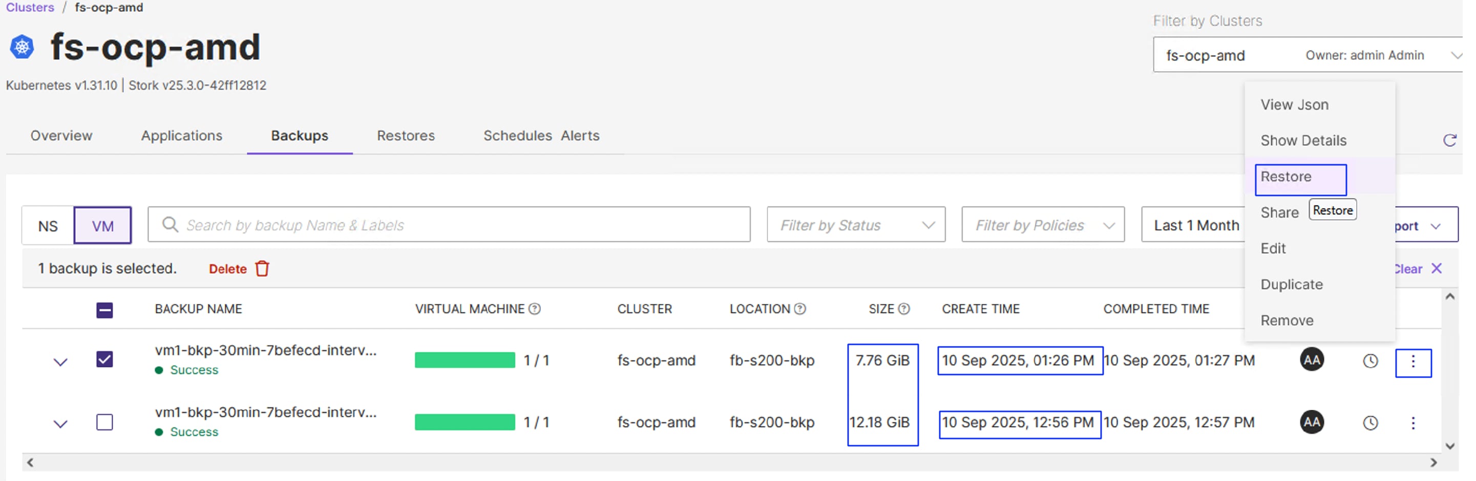
Step 3. The required installation scripts are generated as shown below. Run the generated scripts on the cluster (fs-ocp1.flashstack.local):
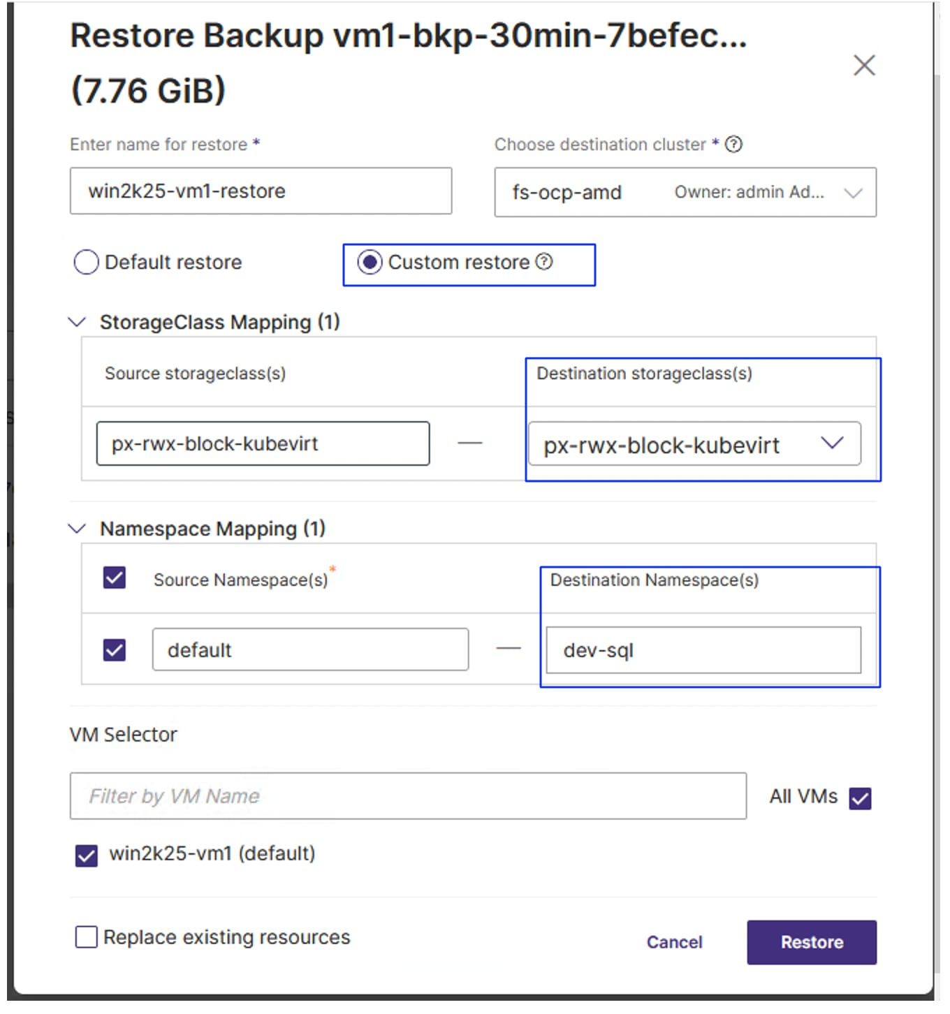
helm install px-central portworx/px-central --namespace px-bkp --create-namespace --version 2.9.1 --set persistentStorage.enabled=true,persistentStorage.storageClassName="px-csi-db",pxbackup.enabled=true
WARNING: Kubernetes configuration file is group-readable. This is insecure. Location: /home/gopu/.kube/config
WARNING: Kubernetes configuration file is world-readable. This is insecure. Location: /home/gopu/.kube/config
NAME: px-central
LAST DEPLOYED: Fri Sep 5 06:11:27 2025
NAMESPACE: px-bkp
STATUS: deployed
REVISION: 1
TEST SUITE: None
NOTES:
Your Release is named: "px-central"
PX-Central is deployed in the namespace: px-bkp
Chart Version: 2.9.1
--------------------------------------------------
Monitor PX-Central Install:
--------------------------------------------------
Wait for job "pxcentral-post-install-hook" status to be in "Completed" state.
kubectl get po --namespace px-bkp -ljob-name=pxcentral-post-install-hook -o wide | awk '{print $1, $3}' | grep -iv error
----------------------------
Features Summary:
----------------------------
PX-Backup: enabled
PX-Monitor: disabled
PX-License-Server: disabled
--------------------------------------------------
Access PX-Central/PX-Backup UI:
--------------------------------------------------
To access PX-Central/PX-Backup UI please refer: https://backup.docs.portworx.com/use-px-backup/configure-ui/#access-the-portworx-backup-ui-using-a-node-ip
Login with the following credentials:
Username: admin
Password: admin
For more information: https://github.com/portworx/helm/blob/master/charts/px-central/README.md
For more information on network pre-requisites: https://docs.portworx.com/portworx-backup-on-prem/install/install-prereq/nw-prereqs.html
--------------------------------------------------
View Pre-Install Report:
--------------------------------------------------
To view the Pre-Install Report, run:
kubectl get cm px-central-report -n px-bkp -o go-template='{{ index .data "report-2.9.1" }}'
Step 4. Wait until all the pods display in the px-bkp namespace. Get the node port of px-backup-ui or px-central-ui services and access the services using http://nodeip:nodeport>.
Step 5. Log in with the default userid and password and reset the admin password.

Step 6. When the password is reset, click Add Cluster to add both application cluster (fs-ocp.flashstack.local) and backup cluster (fs-ocp1.flashstack.local) by using the kubeconfig file. Use the following command to get the kubeconfig files of each cluster. The following screenshot shows adding application cluster (fs-ocp.flashstack.local) with the name fs-ocp-amd.
kubectl config view --flatten --minify
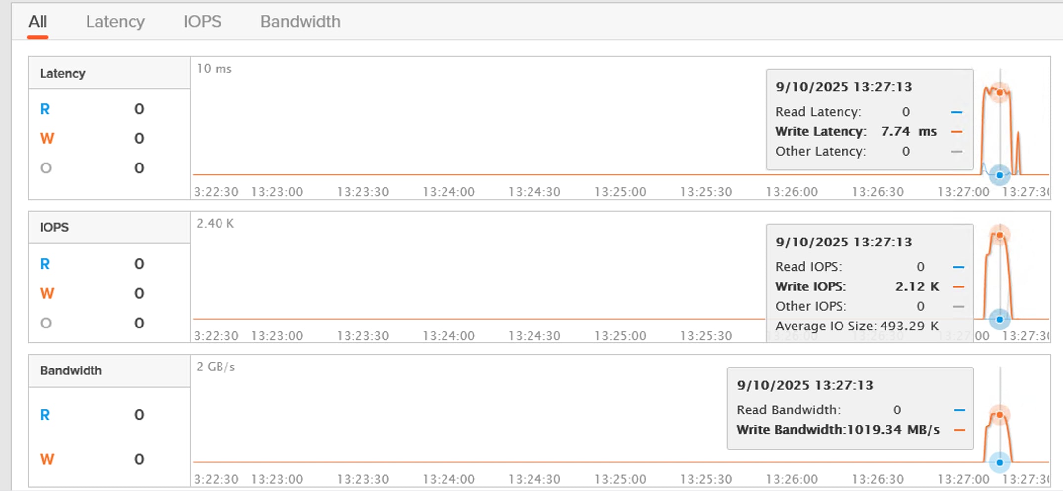
Step 7. Repeat step 6 to add backup cluster (fs-ocp1.flashstack.local).
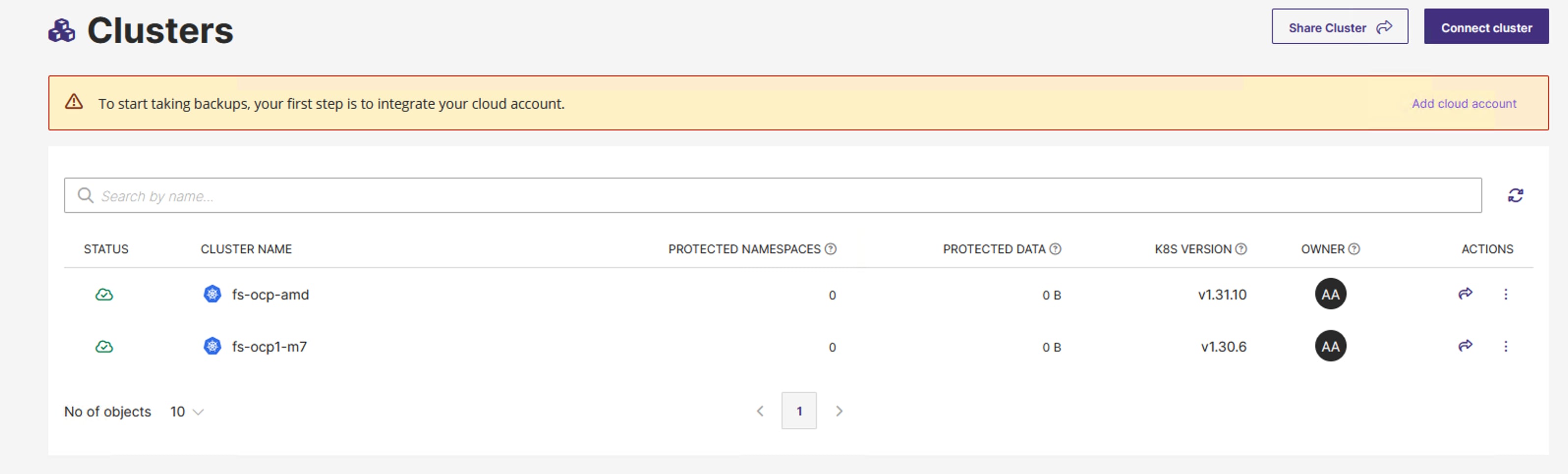
Step 8. Click the application fs-ocp-amd cluster and verify if all the container workloads and virtual machines are populated.
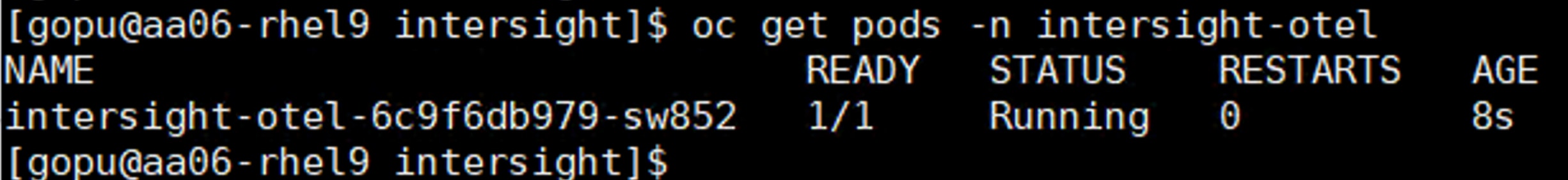
Step 9. Add the backup location. Click the cloud symbol. Add a cloud account by using the Access token, Secrets created in the chapter Pure Storage FlashBlade Configuration.

Step 10. Add backup location as shown below. Note that 192.168.40.40 is the IP addresses on FlashBlade array.
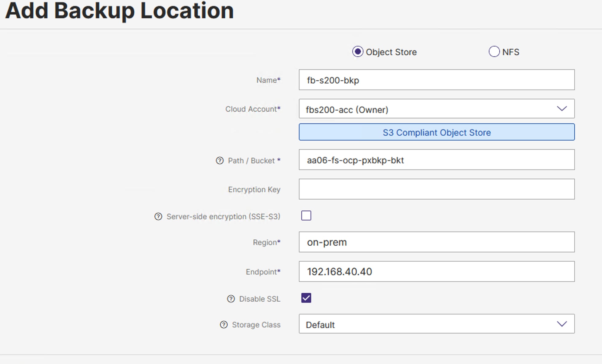

Backup and Restore Virtual Machines
This section provides the procedures to create a backup schedule (policy), backup and restore of the virtual machines to achieve a point in time recovery.
Procedure 1. Backup and Restore of Virtual Machines
Step 1. Click Policies. Create a policy that periodically backs up every 30 minutes.
Step 2. Click + to create policy. Provide a Name for the policy and select Periodic and set 30min and leave the other settings with defaults as show below:

Step 3. Create a backup of a VM, go to Clusters > click fs-ocp-amd cluster > applications > VM. Select the VM (win2k25-vm1) and click Backup. Provide the required details as shown below. Select a backup location and volume snapshot class. Enable On a schedule backups and select schedule policy previously created. Click on Create to start the VM backup.

The full backup of the entire virtual machine will start and complete as shown below:

Step 4. After the completion of the first scheduled backup, wait for 30 minutes to start the second scheduled backup or snapshot. Log into the VM, copy or create some files in the VM. When the second backup completes, log into the VM and make changes.
Note: For this validation, we purposely deleted a few files.
Step 5. Recover the deleted files, by selecting the latest snapshot copy and restore it. Before restoring, pause the next scheduled backup (third backup).
Step 6. Click the Backups tab to view the list backups available for your VMs. The following screenshot shows two backups created in the previous steps with 30 minutes apart:

Step 7. Select the latest backup of the VM and click Restore as shown above. Provide a name to the Restore operation. Select the Destination cluster.
Note: In this validation, the backup is restored on the same application cluster but in a different name space. Therefore, the same application cluster is selected.
Step 8. Click Customer Restore to customize the restore operation. Select the appropriate Storage Class that supports RWX volumes in the destination cluster. Provide a name space in which the VM needs to be restored. Click Restore to start the restore of the VM.

Step 9. After the successful completion of restore, a new VM is created and running in the dev-sql namespace, in the same application cluster as shown below. Verify if the deleted files are available. This verifies that data is being recovered from accidental deletion.
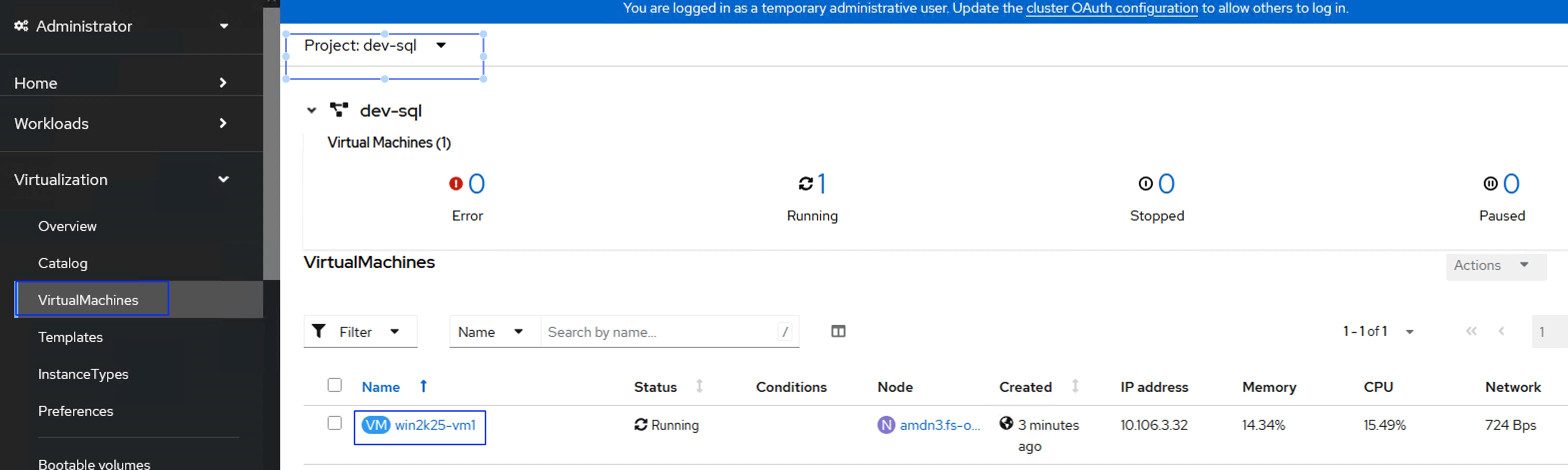
When the backup or restore operations are in progress, you can login to the FlashBlade and check for data traffic. The following screenshot shows nearly 1GB write bandwidth during the backup operation.

Splunk Observability
This chapter contains the following:
● Install and Configure OTEL Collector Agents
This section provides the procedures to install and configure OTEL agents for various components of the solution to gain deep observability capabilities with Splunk Observability Cloud.
The following prerequisites need to be met before installing and configuring Splunk OpenTelemetry Collector (OTEL):
● To install Splunk OpenTelemetry Collector in a Kubernetes cluster environment, either of the destinations (splunkPlatform or splunkObservabilitycloud) to be configured. For this validation, Splunk Observability Cloud is pre-configured and required access to the observability cloud is provided.
● Once access to observability cloud is enabled, generate Realm and Access token with which the OTEL collectors authenticates with Observability cloud and sends the metrics data. To create the Access token and realm, see: https://help.splunk.com/en/splunk-observability-cloud/administer/authentication-and-security/authentication-tokens/org-access-tokens#admin-org-tokens and https://dev.splunk.com/observability/docs/realms_in_endpoints/
● Administrator Access to OpenShift cluster for deploying OTEL collector agents and sending the logs to the Observability cloud.
● Ensure Helm version 3 is installed on the Linux client machine.
Install and Configure OTEL Collector Agents
Procedure 1. Install OpenShift OTEL Collector Kubernetes
Step 1. From the Linux VM (jump host), log into your OpenShift cluster with CLI using kubeconfig or admin user.
Step 2. Create Install otel collector agents for OpenShift by running the following commands from the linux client machine.
Step 3. Add helm repository of Splunk OTEL collector charts.
helm repo add splunk-otel-collector-chart https://signalfx.github.io/splunk-otel-collector-chart
Step 4. Install the Splunk otel collector using values.yaml file. Update the exporters, receivers and processors sections with appropriate values for your environment and run the following command to install the otel collector for your environment. Sample values.yaml file is provided below:
Note: In this sample script, under the receivers section, metrics endpoints and pod names of various components are added.
##create a name space and get into the namespace
oc create namespace otel
oc project otel
helm upgrade ucs-otel-collector --set="distribution=openshift,splunkObservability.accessToken=<XXXXXXX>,clusterName=amd-ocp.flashstack.local,splunkObservability.realm=us1,gateway.enabled=false,environment=flashstack,operatorcrds.install=false,operator.enabled=false,agent.discovery.enabled=true,splunkObservability.profilingEnabled=true" -f values.yaml splunk-otel-collector-chart/splunk-otel-collector
##Sample values.yaml with Receivers for collecting metrics from Kubernetes, GPU DCGM, Nexus and Portworx metrics.
cat values.yaml
readinessProbe:
initialDelaySeconds: 180
livenessProbe:
initialDelaySeconds: 180
agent:
resources:
limits:
cpu: 200m
# This value is being used as a source for default memory_limiter processor configurations
memory: 2000Mi
config:
exporters:
signalfx:
send_otlp_histograms: true
processors:
filter/health:
error_mode: ignore
traces:
span:
- |
(
IsMatch(name, ".*/v1/health/live.*") or
IsMatch(name, ".*/v1/health/ready.*")
)
filter/metrics_to_be_included:
metrics:
# Include only metrics used in charts and detectors
include:
match_type: strict
metric_names:
- cisco_collector_duration_seconds
- cisco_interface_receive_broadcast
- cisco_interface_receive_bytes
- cisco_interface_receive_drops
- cisco_interface_receive_errors
- cisco_interface_receive_multicast
- cisco_interface_transmit_bytes
- cisco_interface_transmit_drops
- cisco_interface_transmit_errors
- cisco_interface_up
- cisco_up
- DCGM_FI_DEV_FB_FREE
- DCGM_FI_DEV_FB_USED
- DCGM_FI_DEV_GPU_TEMP
- DCGM_FI_DEV_GPU_UTIL
- DCGM_FI_DEV_MEM_CLOCK
- DCGM_FI_DEV_MEM_COPY_UTIL
- DCGM_FI_DEV_MEMORY_TEMP
- DCGM_FI_DEV_POWER_USAGE
- DCGM_FI_DEV_SM_CLOCK
- DCGM_FI_DEV_TOTAL_ENERGY_CONSUMPTION
- DCGM_FI_PROF_DRAM_ACTIVE
- DCGM_FI_PROF_GR_ENGINE_ACTIVE
- DCGM_FI_PROF_PCIE_RX_BYTES
- DCGM_FI_PROF_PCIE_TX_BYTES
- DCGM_FI_PROF_PIPE_TENSOR_ACTIVE
- go_memstats_alloc_bytes
- go_memstats_alloc_bytes_total
- go_memstats_buck_hash_sys_bytes
- go_memstats_frees_total
- go_memstats_gc_sys_bytes
- go_memstats_heap_alloc_bytes
- go_memstats_heap_idle_bytes
- go_memstats_heap_inuse_bytes
- go_memstats_heap_objects
- go_memstats_heap_released_bytes
- go_memstats_heap_sys_bytes
- go_memstats_last_gc_time_seconds
- go_memstats_lookups_total
- go_memstats_mallocs_total
- go_memstats_mcache_inuse_bytes
- go_memstats_mcache_sys_bytes
- go_memstats_mspan_inuse_bytes
- go_memstats_mspan_sys_bytes
- go_memstats_next_gc_bytes
- go_memstats_other_sys_bytes
- go_memstats_stack_inuse_bytes
- go_memstats_stack_sys_bytes
- go_memstats_sys_bytes
- go_sched_gomaxprocs_threads
- gpu_cache_usage_perc
- gpu_total_energy_consumption_joules
- http.server.active_requests
- intersight.advisories.nonsecurity.affected_objects
- intersight.advisories.security.affected_objects
- intersight.advisories.security.count
- intersight.alarms.count
- intersight.ucs.fan.speed
- intersight.ucs.host.power
- intersight.ucs.host.temperature
- intersight.ucs.network.receive.rate
- intersight.ucs.network.transmit.rate
- intersight.ucs.network.utilization.average
- intersight.vm_count
- num_request_max
- num_requests_running
- num_requests_waiting
- process_cpu_seconds_total
- process_max_fds
- process_open_fds
- process_resident_memory_bytes
- process_start_time_seconds
- process_virtual_memory_bytes
- process_virtual_memory_max_bytes
- promhttp_metric_handler_requests_in_flight
- promhttp_metric_handler_requests_total
- prompt_tokens_total
- px_cluster_cpu_percent
- px_cluster_disk_total_bytes
- px_cluster_disk_utilized_bytes
- px_cluster_status_nodes_offline
- px_cluster_status_nodes_online
- px_volume_read_latency_seconds
- px_volume_reads_total
- px_volume_readthroughput
- px_volume_write_latency_seconds
- px_volume_writes_total
- px_volume_writethroughput
- redfish_performance_scrape_duration_seconds
- redfish_thermal_fans_lower_threshold_critical
- redfish_thermal_fans_upper_threshold_critical
- redfish_thermal_temperatures_reading_celsius
- request_failure_total
- request_finish_total
- request_success_total
- system.cpu.time
receivers:
kubeletstats:
insecure_skip_verify: true
receiver_creator/nvidia:
# Name of the extensions to watch for endpoints to start and stop.
watch_observers: [ k8s_observer ]
receivers:
prometheus/nexus:
config:
config:
scrape_configs:
- job_name: nexus-metrics
metrics_path: /metrics
scrape_interval: 10s
static_configs:
- targets:
- '`endpoint`:9362'
rule: type == "pod" && labels["app"] == "cisco-exporter"
prometheus/dcgm:
config:
config:
scrape_configs:
- job_name: gpu-metrics
scrape_interval: 10s
static_configs:
- targets:
- '`endpoint`:9400'
rule: type == "pod" && labels["app"] == "nvidia-dcgm-exporter"
prometheus/portworx:
config:
config:
scrape_configs:
- job_name: portworx-metrics
static_configs:
- targets:
- '`endpoint`:17001'
- '`endpoint`:17018'
rule: type == "pod" && labels["name"] == "portworx"
service:
pipelines:
metrics/nvidia-metrics:
exporters:
- signalfx
processors:
- memory_limiter
- filter/metrics_to_be_included
- batch
- resourcedetection
- resource
receivers:
- receiver_creator/nvidia
traces:
processors:
- memory_limiter
- k8sattributes
- batch
- resourcedetection
- resource
- resource/add_environment
- filter/health
Step 5. After deploying the splunk otel collector, wait for pods (collector agents for each node) to come up as shown below:
Note: This splunk otel collector does not include collector agent for Intersight. Therefore, the collector agents for the additional components need to be installed separately.
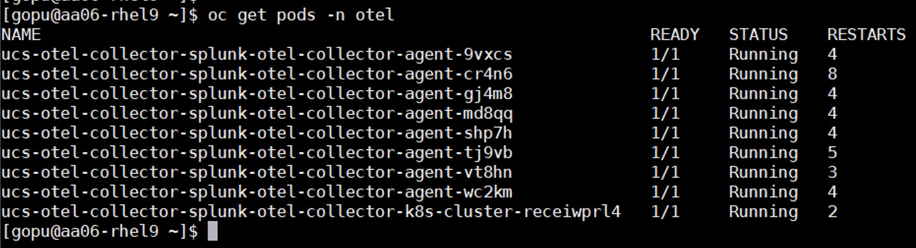
Step 6. Install the Intersight otel collector using the following values.yaml. Set intersight.organization to any arbitrary name:
cat values.yaml
# this deployment will create a pod with both the intersight-otel collector
apiVersion: apps/v1
kind: Deployment
metadata:
name: intersight-otel
spec:
selector:
matchLabels:
app: intersight-otel
template:
metadata:
labels:
app: intersight-otel
component: otel-collector
annotations:
eks.amazonaws.com/compute-type: fargate
spec:
tolerations:
- key: eks.amazonaws.com/compute-type
value: fargate
operator: Equal
effect: NoSchedule
containers:
- name: intersight-otel
securityContext:
allowPrivilegeEscalation: false
capabilities:
drop:
- all
privileged: false
readOnlyRootFilesystem: true
image: ghcr.io/cgascoig/intersight-otel:v0.1.2
# args: ["-c", "/etc/intersight-otel/intersight-otel.toml"]
command:
- "/target/release/intersight_otel"
- "-c"
- "/etc/intersight-otel/intersight-otel.toml"
env:
- name: RUST_LOG
value: "info"
- name: intersight_otel_key_file
value: /etc/intersight-otel-key/intersight.pem
- name: intersight_otel_key_id
valueFrom:
secretKeyRef:
name: intersight-api-credentials
key: intersight-key-id
resources:
requests:
cpu: 100m
memory: 64Mi
limits:
cpu: 200m
memory: 128Mi
volumeMounts:
- name: intersight-otel-config
mountPath: /etc/intersight-otel
readOnly: true
- name: intersight-otel-key
mountPath: /etc/intersight-otel-key
readOnly: true
volumes:
- name: intersight-otel-config
configMap:
name: intersight-otel-config
- name: intersight-otel-key
secret:
secretName: intersight-api-credentials
items:
- key: intersight-key
path: intersight.pem
---
apiVersion: v1
kind: ConfigMap
metadata:
name: intersight-otel-config
data:
intersight-otel.toml: |
otel_collector_endpoint = "http://ucs-otel-collector-splunk-otel-collector-agent.otel.svc.cluster.local:4317"
[[pollers]]
name = "intersight.vm_count"
otel_attributes = { "intersight.account.name" = "POD_NAME", "intersight.fsotype" = "account", "intersight.organization" = "RTPAA06" }
api_query = "api/v1/virtualization/VirtualMachines?$count=true"
aggregator = "result_count"
interval = 60
[[pollers]]
name = "intersight.policy.ntp.count"
otel_attributes = { "intersight.organization" = "RTPAA06" }
api_query = "api/v1/ntp/Policies?$count=true"
aggregator = "result_count"
interval = 60
[[pollers]]
name = "intersight.advisories.security.affected_objects"
otel_attributes = { "intersight.organization" = "RTPAA06" }
api_query = "api/v1/tam/AdvisoryInstances?$count=true&$filter=Advisory/ObjectType eq 'tam.SecurityAdvisory'"
aggregator = "result_count"
interval = 60
[[pollers]]
name = "intersight.advisories.nonsecurity.affected_objects"
otel_attributes = { "intersight.organization" = "RTPAA06" }
api_query = "api/v1/tam/AdvisoryInstances?$count=true&$filter=Advisory/ObjectType ne 'tam.SecurityAdvisory'"
aggregator = "result_count"
interval = 60
[[pollers]]
name = "intersight.advisories.security.count"
otel_attributes = { "intersight.organization" = "RTPAA06" }
api_query = "api/v1/tam/AdvisoryInstances?$filter=Advisory/ObjectType eq 'tam.SecurityAdvisory'&$apply=groupby((Advisory), aggregate($count as count))"
aggregator = "count_results"
interval = 60
[[pollers]]
name = "intersight.alarms.count"
otel_attributes = { severity = "critical", "intersight.organization" = "RTPAA06" }
api_query = "api/v1/cond/Alarms?$filter=Acknowledge eq 'None' and Severity eq 'Critical'&$count=true"
aggregator = "result_count"
interval = 60
[[pollers]]
name = "intersight.alarms.count"
otel_attributes = { severity = "warning", "intersight.organization" = "RTPAA06" }
api_query = "api/v1/cond/Alarms?$filter=Acknowledge eq 'None' and Severity eq 'Warning'&$count=true"
aggregator = "result_count"
interval = 60
[[tspollers]]
name = "hx_performance"
datasource = "hx"
dimensions = ["deviceId"]
filter = { type = "and", fields = [{type = "selector", dimension = "node", value = "allhosts"},{type = "selector", dimension = "datastore", value = "cluster"}]}
aggregations = [{name = "read_ops_per_min", type = "longSum", fieldName = "sumReadOps"}, {name = "write_ops_per_min", type = "longSum",fieldName = "sumWriteOps"}, {name = "read_tp_bytes_per_min", type = "longSum", fieldName = "sumReadBytes"},{name = "write_tp_bytes_per_min", type = "longSum", fieldName = "sumWriteBytes"},{name = "sum_read_latency",type = "longSum", fieldName = "sumReadLatency"},{name = "sum_write_latency",type = "longSum", fieldName = "sumWriteLatency"}]
post_aggregations = [{type = "arithmetic",name = "intersight.hyperflex.read.iops",fn = "/",fields = [{type = "fieldAccess",name = "read_ops_per_min",fieldName = "read_ops_per_min"},{type = "constant",name = "const",value = 300}]}, {type = "arithmetic",name = "intersight.hyperflex.write.iops",fn = "/",fields = [{type = "fieldAccess",name = "write_ops_per_min",fieldName = "write_ops_per_min"},{type = "constant",name = "const",value = 300}]},{type = "arithmetic", name = "intersight.hyperflex.read.throughput", fn = "/", fields = [{type = "fieldAccess", name = "read_tp_bytes_per_min", fieldName = "read_tp_bytes_per_min"},{type = "constant", name = "const", value = 300}]},{type = "arithmetic", name = "intersight.hyperflex.write.throughput", fn = "/", fields = [{type = "fieldAccess", name = "write_tp_bytes_per_min", fieldName = "write_tp_bytes_per_min"},{type = "constant", name = "const", value = 300}]},{type = "arithmetic", name = "intersight.hyperflex.read.latency", fn = "/", fields = [{type = "fieldAccess", name = "sum_read_latency", fieldName = "sum_read_latency"},{type = "fieldAccess",name = "read_ops_per_min", fieldName = "read_ops_per_min"}]},{type = "arithmetic", name = "intersight.hyperflex.write.latency", fn = "/", fields = [{type = "fieldAccess", name = "sum_write_latency",fieldName = "sum_write_latency"},{type = "fieldAccess", name = "write_ops_per_min", fieldName = "write_ops_per_min"}]}]
field_names = ["intersight.hyperflex.read.iops", "intersight.hyperflex.write.iops", "intersight.hyperflex.read.throughput", "intersight.hyperflex.write.throughput", "intersight.hyperflex.read.latency", "intersight.hyperflex.write.latency"]
otel_dimension_to_attribute_map = { deviceId = "intersight.hyperflex.device.id" }
otel_attributes = { "intersight.account.name" = "POD_NAME", "intersight.fsotype" = "hyperflex_cluster", "intersight.organization" = "RTPAA06" }
interval = 60
[[tspollers]]
name = "ucs_network_utilization"
datasource = "NetworkInterfaces"
dimensions = ["host.name"]
filter = { type = "and", fields = [{type = "selector", dimension = "instrument.name", value = "hw.network"}]}
aggregations = [{type = "longSum", name = "count", fieldName = "hw.network.bandwidth.utilization_all_count"}, {type = "doubleSum", name = "hw.network.bandwidth.utilization_all-Sum", fieldName = "hw.network.bandwidth.utilization_all"}]
post_aggregations = [{type = "arithmetic", name = "intersight.ucs.network.utilization.average", fn = "/", fields = [{type = "fieldAccess", name = "hw.network.bandwidth.utilization_all-Sum",fieldName = "hw.network.bandwidth.utilization_all-Sum"},{type = "fieldAccess", name = "count", fieldName = "count"}]}]
field_names = ["intersight.ucs.network.utilization.average"]
otel_dimension_to_attribute_map = { "host.name" = "intersight.host.name" }
otel_attributes = { "intersight.account.name" = "POD_NAME", "intersight.fsotype" = "ucs_domain", "intersight.organization" = "RTPAA06" }
interval = 60
[[tspollers]]
name = "ucs_network_bytes"
datasource = "NetworkInterfaces"
dimensions = ["host.name"]
filter = { type = "and", fields = [{type = "selector", dimension = "instrument.name", value = "hw.network"}]}
aggregations = [{"type" = "doubleSum", "name" = "hw.network.io_transmit_duration-Sum", "fieldName" = "hw.network.io_transmit_duration"}, {"type" = "longSum", "name" = "hw.network.io_transmit-Sum", "fieldName" = "hw.network.io_transmit" }, {"type" = "doubleSum", "name" = "hw.network.io_receive_duration-Sum", "fieldName" = "hw.network.io_receive_duration"}, {"type" = "longSum", "name" = "hw.network.io_receive-Sum", "fieldName" = "hw.network.io_receive" }]
post_aggregations = [{type = "arithmetic", name = "intersight.ucs.network.transmit.rate", fn = "/", fields = [{type = "fieldAccess", name = "hw.network.io_transmit-Sum",fieldName = "hw.network.io_transmit-Sum"},{type = "fieldAccess", name = "hw.network.io_transmit_duration-Sum", fieldName = "hw.network.io_transmit_duration-Sum"}]}, {type = "arithmetic", name = "intersight.ucs.network.receive.rate", fn = "/", fields = [{type = "fieldAccess", name = "hw.network.io_receive-Sum",fieldName = "hw.network.io_receive-Sum"},{type = "fieldAccess", name = "hw.network.io_transmit_receive-Sum", fieldName = "hw.network.io_receive_duration-Sum"}]}]
field_names = ["intersight.ucs.network.transmit.rate", "intersight.ucs.network.receive.rate"]
otel_dimension_to_attribute_map = { "host.name" = "intersight.host.name" }
otel_attributes = { "intersight.account.name" = "POD_NAME", "intersight.fsotype" = "ucs_domain", "intersight.organization" = "RTPAA06" }
interval = 60
[[tspollers]]
name = "ucs_fan_speed"
datasource = "PhysicalEntities"
dimensions = ["host.name"]
filter = { type = "and", fields = [{type = "selector", dimension = "instrument.name", value = "hw.fan"}]}
aggregations = [{type = "longSum", name = "count", fieldName = "hw.fan.speed_count"}, {type = "longSum", name = "hw.fan.speed-Sum", fieldName = "hw.fan.speed"}]
post_aggregations = [{"type" = "expression", "name" = "intersight.ucs.fan.speed", "expression" = "(\"hw.fan.speed-Sum\" / \"count\")"}]
field_names = ["intersight.ucs.fan.speed"]
otel_dimension_to_attribute_map = { "host.name" = "intersight.host.name" }
otel_attributes = { "intersight.account.name" = "POD_NAME", "intersight.fsotype" = "ucs_domain", "intersight.organization" = "RTPAA06" }
interval = 60
[[tspollers]]
name = "ucs_host_power"
datasource = "PhysicalEntities"
dimensions = ["name"]
filter = { type = "and", fields = [{type = "selector", dimension = "instrument.name", value = "hw.host"}]}
aggregations = [{type = "longSum", name = "count", fieldName = "hw.host.power_count"}, {type = "doubleSum", name = "hw.host.power-Sum", fieldName = "hw.host.power"}]
post_aggregations = [{"type" = "expression", "name" = "intersight.ucs.host.power", "expression" = "(\"hw.host.power-Sum\" / \"count\")"}]
field_names = ["intersight.ucs.host.power"]
otel_dimension_to_attribute_map = { "name" = "intersight.name" }
otel_attributes = { "intersight.account.name" = "POD_NAME", "intersight.fsotype" = "ucs_domain", "intersight.organization" = "RTPAA06" }
interval = 60
[[tspollers]]
name = "ucs_host_temperature"
datasource = "PhysicalEntities"
dimensions = ["host.name"]
filter = { type = "and", fields = [{type = "selector", dimension = "instrument.name", value = "hw.temperature"}, {type = "selector", dimension = "host.type", value = "compute.Blade"}]}
aggregations = [{type = "longSum", name = "count", fieldName = "hw.temperature_count"}, {type = "doubleSum", name = "hw.temperature-Sum", fieldName = "hw.temperature"}]
post_aggregations = [{"type" = "expression", "name" = "intersight.ucs.host.temperature", "expression" = "(\"hw.temperature-Sum\" / \"count\")"}]
field_names = ["intersight.ucs.host.temperature"]
otel_dimension_to_attribute_map = { "host.name" = "intersight.host.name" }
otel_attributes = { "intersight.account.name" = "POD_NAME", "intersight.fsotype" = "ucs_domain", "intersight.organization" = "RTPAA06" }
interval = 60
## create name space for Intel Otel agent
oc create ns intersight-otel
## apply the configuration.
oc apply -f values.yaml -n intersight-otel
Step 7. After installing the otel agents for Intersight, wait for the pod to come up.

Step 8. Portworx metrics can be pushed to the Splunk observability cloud by enabling the user defined project monitoring by running the following:
cat enableUserwlMonitoring.yaml
apiVersion: v1
kind: ConfigMap
metadata:
name: cluster-monitoring-config
namespace: openshift-monitoring
data:
config.yaml: |
enableUserWorkload: true
### apply the config
oc apply -f enableUserwlMonitoring.yaml
Step 9. Log into the Splunk Observability site with your credentials and start creating your own dashboards and dashboard groups. You can also leverage built-in dashboards by importing them and customize them as per your requirements. The following dashboards have been built using the metrics pushed by Otel agents running on the OpenShift cluster. For more information about dashboards, go to: https://help.splunk.com/en/splunk-observability-cloud/create-dashboards-and-charts/create-dashboards
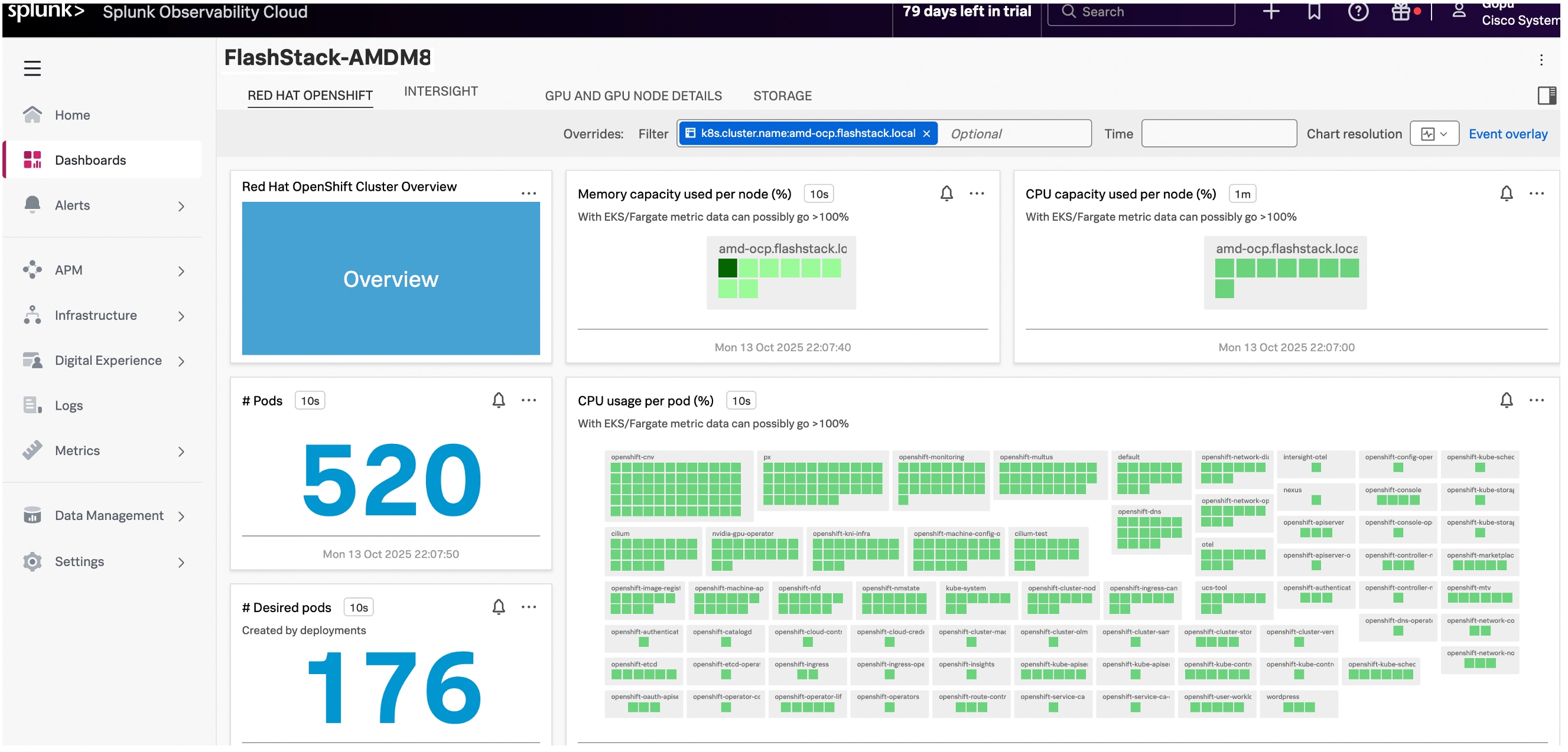
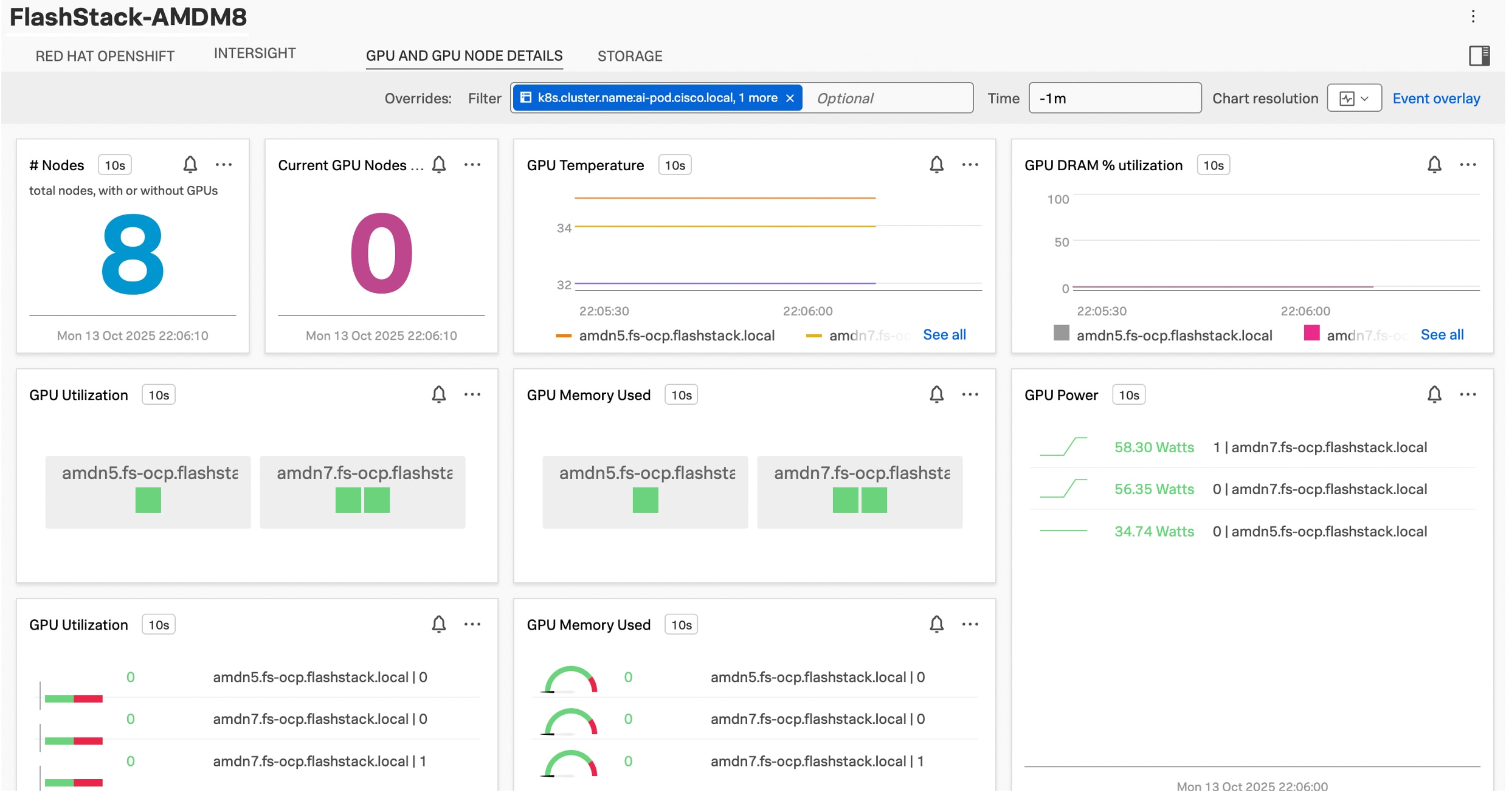
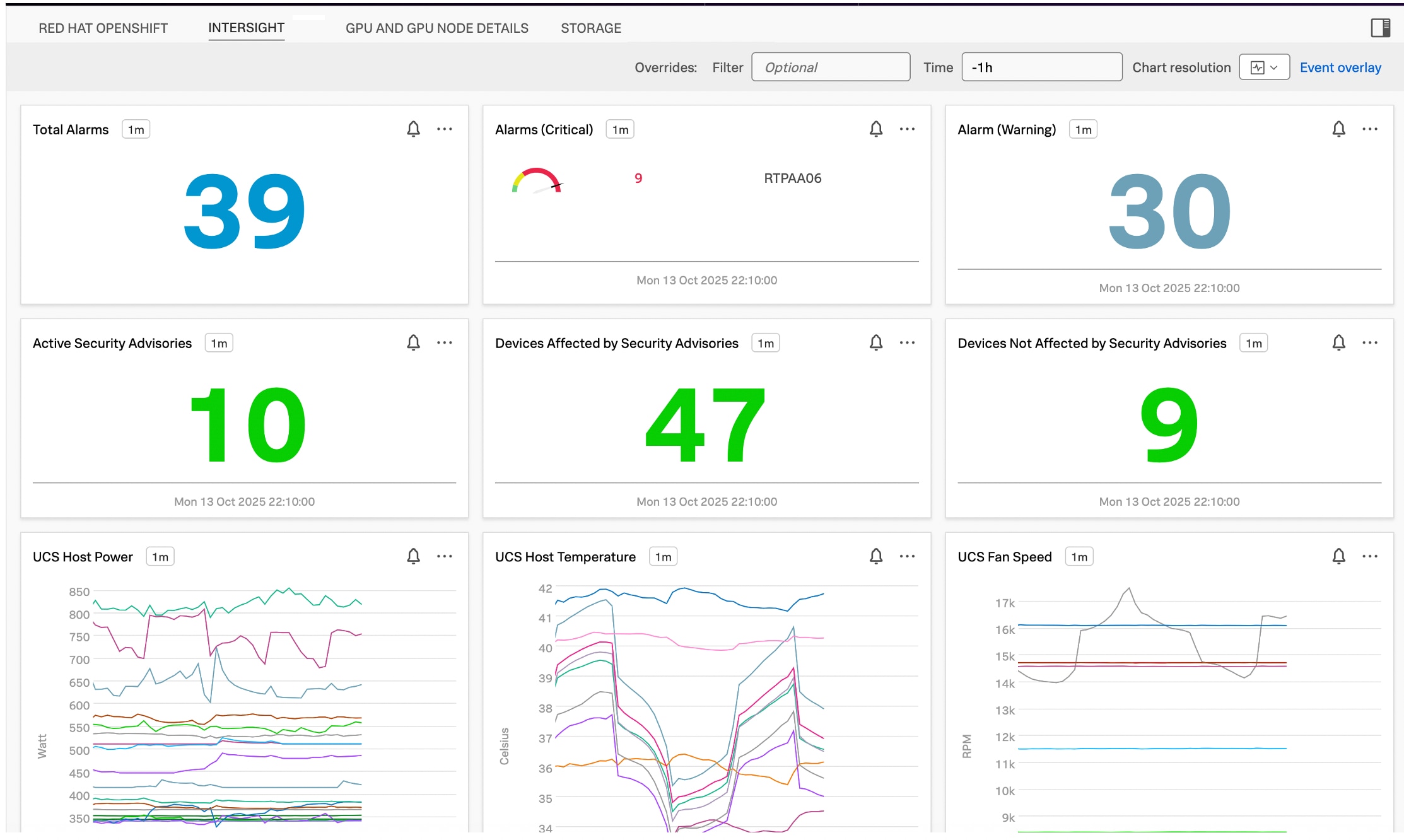
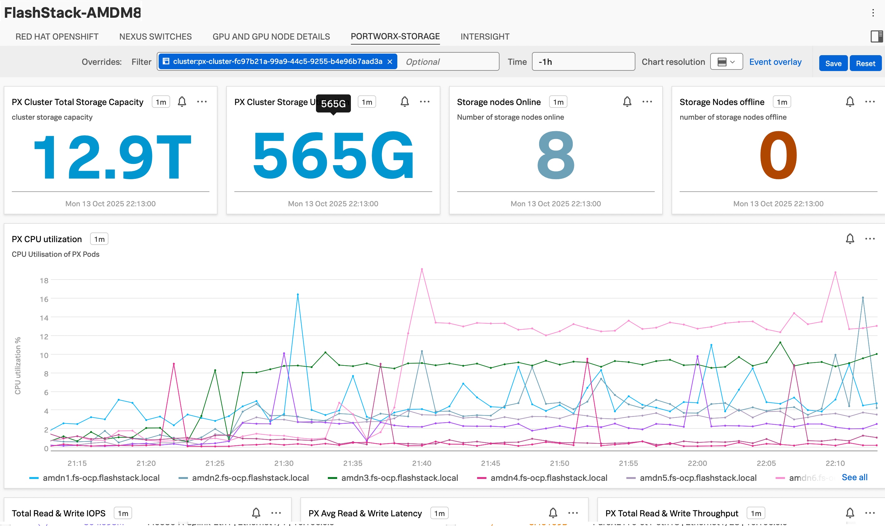
About the Authors
Gopu Narasimha Reddy, Technical Marketing Engineer, Cisco Systems, Inc.
Gopu Narasimha Reddy is a Technical Marketing engineer with the UCS Solutions team at Cisco. He is currently focused on validating and developing Cisco UCS infrastructure solutions for enterprise workloads with different operating environments including Windows, VMware, Linux, and OpenShift. Gopu is also involved in publishing database benchmarks on Cisco UCS servers. His areas of interest include building and validating reference architectures, and development of sizing tools in addition to assisting customers in database deployments.
Vijay Bhaskar Kulari, Solution Architect, Pure Storage, Inc.
Vijay Kulari works at Pure Storage, part of the Portworx Technical Marketing team. He specializes in designing, developing, and optimizing solutions across Storage, Converged Infrastructure, Cloud, and Container technologies. His role includes establishing best practices, streamlining automation, and creating technical content. As an experienced Solution Architect, Vijay has a strong background in VMware products, storage solutions, converged and hyper-converged infrastructure, and container platforms
Acknowledgements
For their support and contribution to the design, validation, and creation of this Cisco Validated Design, the authors would like to thank:
● Chris O’Brien, Senior Director, Technical Marketing, Cisco Systems, Inc.
● John George, Technical Marketing Engineer, Cisco Systems, Inc.
● Paniraja Koppa, Technical Marketing Engineer, Cisco Systems, Inc.
● Andrew Riconosciuto, Customer Success, Isovalent@Cisco
● Piotr Jablonski, Customer Success, Isovalent@Cisco
● Marcos Hernandez, Distinguished Engineer, Isovalent@Cisco
● Craig Waters, Solutions Director, Pure Storage, Inc.
● Eric Shanks, Principal Technical Marketing Engineer, Pure Storage, Inc.
This appendix contains the following:
● Appendix A – References used in this guide
Appendix A – References used in this guide
Compute
Cisco Intersight: https://www.intersight.com
Cisco Intersight Managed Mode: https://www.cisco.com/c/en/us/td/docs/unified_computing/Intersight/b_Intersight_Managed_Mode_Configuration_Guide.html
Cisco Unified Computing System: http://www.cisco.com/en/US/products/ps10265/index.html
Cisco UCS M8 AMD Servers: https://www.cisco.com/c/m/en_us/solutions/computing/ucs-amd.html#~models
Cisco UCS 6536 Fabric Interconnect Data Sheet: https://www.cisco.com/c/en/us/products/collateral/servers-unified-computing/ucs6536-fabric-interconnect-ds.html
Network
Cisco Nexus 9300-GX Series Switches: https://www.cisco.com/c/en/us/products/collateral/switches/nexus-9000-series-switches/nexus-9300-gx-series-switches-ds.html
Pure Storage
FlashStack: https://flashstack.com
Pure Storage FlashArray//X: https://www.purestorage.com/products/unified-block-file-storage/flasharray-x.html
Pure Storage FlashArray//XL: https://www.purestorage.com/products/unified-block-file-storage/flasharray-xl.html
Pure Storage FlashBlade//S: https://www.purestorage.com/products/unstructured-data-storage/flashblade-s.html
Red Hat OpenShift
Documentation: https://docs.openshift.com/
Red Hat OpenShift Container Platform: https://www.redhat.com/en/technologies/cloud-computing/openshift/container-platform
Red Hat OpenShift Virtualization: https://docs.redhat.com/en/documentation/openshift_container_platform/4.16/html/virtualization/index
Red Hat Hybrid Cloud Console: https://cloud.redhat.com/
Isovalent Networking for Kubernetes
Isovalent Enterprise: https://docs.isovalent.com/documentation.html
Migration from OpenShift OVN: https://docs.isovalent.com/operations-guide/migrating/ovn-kubernetes.html
Portworx Enterprise
Portworx Enterprise documentation: https://docs.portworx.com/
Portworx Backup
Portworx Backup documentation: https://docs.portworx.com/portworx-backup-on-prem/
Cisco Splunk Observability Cloud
Built-in Dashboards: https://help.splunk.com/en/splunk-observability-cloud/create-dashboards-and-charts/create-dashboards
Interoperability Matrix
Cisco UCS Hardware Compatibility Matrix: https://ucshcltool.cloudapps.cisco.com/public/
Pure Storage FlashStack Compatibility Matrix. This interoperability list will require a support login from Pure: https://support.purestorage.com/bundle/m_product_information/page/FlashStack/Product_Information/topics/reference/r_flashstack_compatibility_matrix.html
Feedback
For comments and suggestions about this guide and related guides, join the discussion on Cisco Community here: https://cs.co/en-cvds.
CVD Program
"DESIGNS") IN THIS MANUAL ARE PRESENTED "AS IS," WITH ALL FAULTS. CISCO AND ITS SUPPLIERS DISCLAIM ALL WARRANTIES, INCLUDING, WITHOUT LIMITATION, THE WARRANTY OF MERCHANTABILITY, FITNESS FOR A PARTICULAR PURPOSE AND NONINFRINGEMENT OR ARISING FROM A COURSE OF DEALING, USAGE, OR TRADE PRACTICE. IN NO EVENT SHALL CISCO OR ITS SUPPLIERS BE LIABLE FOR ANY INDIRECT, SPECIAL, CONSEQUENTIAL, OR INCIDENTAL DAMAGES, INCLUDING, WITHOUT LIMITATION, LOST PROFITS OR LOSS OR DAMAGE TO DATA ARISING OUT OF THE USE OR INABILITY TO USE THE DESIGNS, EVEN IF CISCO OR ITS SUPPLIERS HAVE BEEN ADVISED OF THE POSSIBILITY OF SUCH DAMAGES.
THE DESIGNS ARE SUBJECT TO CHANGE WITHOUT NOTICE. USERS ARE SOLELY RESPONSIBLE FOR THEIR APPLICATION OF THE DESIGNS. THE DESIGNS DO NOT CONSTITUTE THE TECHNICAL OR OTHER PROFESSIONAL ADVICE OF CISCO, ITS SUPPLIERS OR PARTNERS. USERS SHOULD CONSULT THEIR OWN TECHNICAL ADVISORS BEFORE IMPLEMENTING THE DESIGNS. RESULTS MAY VARY DEPENDING ON FACTORS NOT TESTED BY CISCO.
CCDE, CCENT, Cisco Eos, Cisco Lumin, Cisco Nexus, Cisco StadiumVision, Cisco TelePresence, Cisco WebEx, the Cisco logo, DCE, and Welcome to the Human Network are trademarks; Changing the Way We Work, Live, Play, and Learn and Cisco Store are service marks; and Access Registrar, Aironet, AsyncOS, Bringing the Meeting To You, Catalyst, CCDA, CCDP, CCIE, CCIP, CCNA, CCNP, CCSP, CCVP, Cisco, the Cisco Certified Internetwork Expert logo, Cisco IOS, Cisco Press, Cisco Systems, Cisco Systems Capital, the Cisco Systems logo, Cisco Unified Computing System (Cisco UCS), Cisco UCS B-Series Blade Servers, Cisco UCS C-Series Rack Servers, Cisco UCS S-Series Storage Servers, Cisco UCS X-Series, Cisco UCS Manager, Cisco UCS Management Software, Cisco Unified Fabric, Cisco Application Centric Infrastructure, Cisco Nexus 9000 Series, Cisco Nexus 7000 Series. Cisco Prime Data Center Network Manager, Cisco NX-OS Software, Cisco MDS Series, Cisco Unity, Collaboration Without Limitation, EtherFast, EtherSwitch, Event Center, Fast Step, Follow Me Browsing, FormShare, GigaDrive, HomeLink, Internet Quotient, IOS, iPhone, iQuick Study, LightStream, Linksys, MediaTone, MeetingPlace, MeetingPlace Chime Sound, MGX, Networkers, Networking Academy, Network Registrar, PCNow, PIX, PowerPanels, ProConnect, ScriptShare, SenderBase, SMARTnet, Spectrum Expert, StackWise, The Fastest Way to Increase Your Internet Quotient, TransPath, WebEx, and the WebEx logo are registered trade-marks of Cisco Systems, Inc. and/or its affiliates in the United States and certain other countries. (LDW_P6)
All other trademarks mentioned in this document or website are the property of their respective owners. The use of the word partner does not imply a partnership relationship between Cisco and any other company. (0809R)