FlexPod Datacenter with Citrix Virtual Apps & Desktops 1912 LTSR and VMware vSphere 7 for up to 6000 Seats
Available Languages
Bias-Free Language
The documentation set for this product strives to use bias-free language. For the purposes of this documentation set, bias-free is defined as language that does not imply discrimination based on age, disability, gender, racial identity, ethnic identity, sexual orientation, socioeconomic status, and intersectionality. Exceptions may be present in the documentation due to language that is hardcoded in the user interfaces of the product software, language used based on RFP documentation, or language that is used by a referenced third-party product. Learn more about how Cisco is using Inclusive Language.
- US/Canada 800-553-2447
- Worldwide Support Phone Numbers
- All Tools
 Feedback
 Feedback

FlexPod Datacenter with Citrix Virtual Apps & Desktops 1912 LTSR and VMware vSphere 7 for up to 6000 Seats
Deployment Guide for a 6000 Seat Virtual Desktop Infrastructure Built on Cisco UCS B200 M5 with NetApp AFF A-Series using Citrix 1912 LTSR, and VMware vSphere ESXi 7 Hypervisor Platform
Published: May 2021
![]()
In partnership with
![]()
About the Cisco Validated Design Program
The Cisco Validated Design (CVD) program consists of systems and solutions designed, tested, and documented to facilitate faster, more reliable, and more predictable customer deployments. For more information, go to:
http://www.cisco.com/go/designzone.
ALL DESIGNS, SPECIFICATIONS, STATEMENTS, INFORMATION, AND RECOMMENDATIONS (COLLECTIVELY, "DESIGNS") IN THIS MANUAL ARE PRESENTED "AS IS," WITH ALL FAULTS. CISCO AND ITS SUPPLIERS DISCLAIM ALL WARRANTIES, INCLUDING, WITHOUT LIMITATION, THE WARRANTY OF MERCHANTABILITY, FITNESS FOR A PARTICULAR PURPOSE AND NONINFRINGEMENT OR ARISING FROM A COURSE OF DEALING, USAGE, OR TRADE PRACTICE. IN NO EVENT SHALL CISCO OR ITS SUPPLIERS BE LIABLE FOR ANY INDIRECT, SPECIAL, CONSEQUENTIAL, OR INCIDENTAL DAMAGES, INCLUDING, WITHOUT LIMITATION, LOST PROFITS OR LOSS OR DAMAGE TO DATA ARISING OUT OF THE USE OR INABILITY TO USE THE DESIGNS, EVEN IF CISCO OR ITS SUPPLIERS HAVE BEEN ADVISED OF THE POSSIBILITY OF SUCH DAMAGES.
THE DESIGNS ARE SUBJECT TO CHANGE WITHOUT NOTICE. USERS ARE SOLELY RESPONSIBLE FOR THEIR APPLICATION OF THE DESIGNS. THE DESIGNS DO NOT CONSTITUTE THE TECHNICAL OR OTHER PROFESSIONAL ADVICE OF CISCO, ITS SUPPLIERS OR PARTNERS. USERS SHOULD CONSULT THEIR OWN TECHNICAL ADVISORS BEFORE IMPLEMENTING THE DESIGNS. RESULTS MAY VARY DEPENDING ON FACTORS NOT TESTED BY CISCO.
CCDE, CCENT, Cisco Eos, Cisco Lumin, Cisco Nexus, Cisco StadiumVision, Cisco TelePresence, Cisco WebEx, the Cisco logo, DCE, and Welcome to the Human Network are trademarks; Changing the Way We Work, Live, Play, and Learn and Cisco Store are service marks; and Access Registrar, Aironet, AsyncOS, Bringing the Meeting To You, Catalyst, CCDA, CCDP, CCIE, CCIP, CCNA, CCNP, CCSP, CCVP, Cisco, the Cisco Certified Internetwork Expert logo, Cisco IOS, Cisco Press, Cisco Systems, Cisco Systems Capital, the Cisco Systems logo, Cisco Unified Computing System (Cisco UCS), Cisco UCS B-Series Blade Servers, Cisco UCS C-Series Rack Servers, Cisco UCS S-Series Storage Servers, Cisco UCS Manager, Cisco UCS Management Software, Cisco Unified Fabric, Cisco Application Centric Infrastructure, Cisco Nexus 9000 Series, Cisco Nexus 7000 Series. Cisco Prime Data Center Network Manager, Cisco NX-OS Software, Cisco MDS Series, Cisco Unity, Collaboration Without Limitation, EtherFast, EtherSwitch, Event Center, Fast Step, Follow Me Browsing, FormShare, GigaDrive, HomeLink, Internet Quotient, IOS, iPhone, iQuick Study, LightStream, Linksys, MediaTone, MeetingPlace, MeetingPlace Chime Sound, MGX, Networkers, Networking Academy, Network Registrar, PCNow, PIX, PowerPanels, ProConnect, ScriptShare, SenderBase, SMARTnet, Spectrum Expert, StackWise, The Fastest Way to Increase Your Internet Quotient, TransPath, WebEx, and the WebEx logo are registered trademarks of Cisco Systems, Inc. and/or its affiliates in the United States and certain other countries. (LDW)
All other trademarks mentioned in this document or website are the property of their respective owners. The use of the word partner does not imply a partnership relationship between Cisco and any other company. (0809R)
© 2021 Cisco Systems, Inc. All rights reserved.
Cisco® Validated Designs include systems and solutions that are designed, tested, and documented to facilitate and improve customer deployments. These designs incorporate a wide range of technologies and products into a portfolio of solutions that have been developed to address the business needs of customers. Cisco and NetApp have partnered to deliver this document, which serves as a specific step by step guide for implementing this solution. This Cisco Validated Design provides an efficient architectural design that is based on customer requirements. The solution that follows is a validated approach to deploying Cisco, NetApp, Citrix and VMware technologies as a shared, high performance, resilient, virtual desktop infrastructure.
This document provides a Reference Architecture for a virtual desktop and application design using Citrix RDS/Citrix Virtual Apps & Desktops 1912 LTSR built on Cisco UCS with a NetApp® All Flash FAS (AFF) A400 storage and the VMware vSphere ESXi 7.01 hypervisor platform.
The landscape of desktop and application virtualization is changing constantly. The new M5 high-performance Cisco UCS Blade Servers and Cisco UCS unified fabric combined as part of the FlexPod Proven Infrastructure with the latest generation NetApp AFF storage result in a more compact, more powerful, more reliable, and more efficient platform.
This document provides the architecture and design of a virtual desktop infrastructure for up to 6000 End User Compute users. The solution virtualized on fifth generation Cisco UCS B200 M5 blade servers, booting VMware vSphere 7.01 Update 1 through FC SAN from the AFF A400 storage array. The virtual desktops are powered using Citrix Provisioning Server 1912 LTSR and Citrix RDS/Citrix Virtual Apps & Desktops 1912 LTSR, with a mix of RDS hosted shared desktops (6000), pooled/non-persistent hosted virtual Windows 10 desktops (5000) and persistent hosted virtual Windows 10 desktops provisioned with Citrix Machine Creation Services (5000) to support the user population. Where applicable, the document provides best practice recommendations and sizing guidelines for customer deployments of this solution.
The solution is fully capable of supporting hardware accelerated graphicss workloads. The Cisco UCS B200 M5 server supports up to two NVIDIA P6 cards for high density, high-performance graphics workload support. See our Cisco Graphics White Paper for details on how to integrate NVIDIA GPU with Citrix Virtual Apps & Desktops.
The solution provides outstanding virtual desktop end-user experience as measured by the Login VSI 4.1.40 Knowledge Worker workload running in benchmark mode.
The 6000-seat solution provides a large-scale building block that can be replicated to confidently scale-out to tens of thousands of users.
Solution Overview
The current industry trend in data center design is towards shared infrastructures. By using virtualization along with pre-validated IT platforms, enterprise customers have embarked on the journey to the cloud by moving away from application silos and toward shared infrastructure that can be quickly deployed, thereby increasing agility, and reducing costs. Cisco, NetApp storage, and VMware have partnered to deliver this Cisco Validated Design, which uses best of breed storage, server, and network components to serve for the foundation for desktop virtualization workloads, enabling efficient architectural designs that can be quickly and confidently deployed.
The audience for this document includes, but is not limited to; sales engineers, field consultants, professional services, IT managers, partner engineers, and customers who want to take advantage of an infrastructure built to deliver IT efficiency and enable IT innovation.
This document provides a step-by-step design, configuration, and implementation guide for the Cisco Validated Design for a large-scale Citrix Virtual Apps & Desktops 1912 LTSR mixed workload solution with NetApp AFF A400, NS224 NVMe Disk Shelf, Cisco UCS Blade Servers, Cisco Nexus 9000 series Ethernet switches and Cisco MDS 9000 series fibre channel switches.
This is the first Citrix Virtual Apps & Desktops desktop virtualization Cisco Validated Design with Cisco UCS 5th generation servers and a NetApp AFF A-Series system.
It incorporates the following features:
● Cisco UCS B200 M5 blade servers with Intel Xeon Scalable Family processors and 2933 MHz memory
● Validation of Cisco Nexus 9000 with NetApp AFF A400 system
● Validation of Cisco MDS 9000 with NetApp AFF A400 system
● Support for the Cisco UCS 4.1(2b) release and Cisco UCS B200-M5 servers
● Support for the latest release of NetApp AFF A400 hardware and NetApp ONTAP® 9.7
● VMware vSphere 7.01 U1 Hypervisor
● Citrix Virtual Apps & Desktops 1912 LTSR Server 2019 RDS hosted shared virtual desktops
● Citrix Virtual Apps & Desktops 1912 LTSR non-persistent hosted virtual Windows 10 desktops provisioned with Citrix Provisioning Services
● Citrix Virtual Apps & Desktops 1912 LTSR persistent full clones hosted virtual Windows 10 desktops provisioned with Citrix Machine Creation Services
The data center market segment is shifting toward heavily virtualized private, hybrid and public cloud computing models running on industry-standard systems. These environments require uniform design points that can be repeated for ease of management and scalability.
These factors have led to the need for predesigned computing, networking and storage building blocks optimized to lower the initial design cost, simplify management, and enable horizontal scalability and high levels of utilization.
The use cases include:
● Enterprise Datacenter
● Service Provider Datacenter
● Large Commercial Datacenter
This Cisco Validated Design prescribes a defined set of hardware and software that serves as an integrated foundation for both Citrix Virtual Apps & Desktops Microsoft Windows 10 virtual desktops and Citrix RDS server desktop sessions based on Microsoft Server 2019.
The mixed workload solution includes NetApp AFF A400 storage, Cisco Nexus® and MDS networking, the Cisco Unified Computing System (Cisco UCS®), Citrix Virtual Apps & Desktops and VMware vSphere software in a single package. The design is space optimized such that the network, compute, and storage required can be housed in one data center rack. Switch port density enables the networking components to accommodate multiple compute and storage configurations of this kind.
The infrastructure is deployed to provide Fibre Channel-booted hosts with access to shared storage using NFS mounts. The reference architecture reinforces the "wire-once" strategy because as additional storage is added to the architecture, no re-cabling is required from the hosts to the Cisco UCS fabric interconnect.
The combination of technologies from Cisco Systems, Inc., NetApp Inc., Citrix Inc., and VMware Inc., produced a highly efficient, robust, and affordable desktop virtualization solution for a hosted virtual desktop and hosted shared desktop mixed deployment supporting different use cases. Key components of the solution include the following:
● More power, same size. Cisco UCS B200 M5 half-width blade with dual 20-core 2.1 GHz Intel ® Xeon ® Gold (6230) processors and 768 GB of memory supports more virtual desktop workloads than the previously released generation processors on the same hardware. The Intel 20-core 2.1 GHz Intel ® Xeon ® Gold (6230) processors used in this study provided a balance between increased per-blade capacity and cost.
● Fault-tolerance with high availability built into the design. The various designs are based on using one Unified Computing System chassis with multiple Cisco UCS B200 M5 blades for virtualized desktop and infrastructure workloads. The design provides N+1 server fault tolerance for hosted virtual desktops, hosted shared desktops and infrastructure services.
● Stress-tested to the limits during simulated login storms. All 6000 simulated users logged in and started running workloads up to steady state in 48-minutes without overwhelming the processors, exhausting memory, or exhausting the storage subsystems, providing customers with a desktop virtualization system that can easily handle the most demanding login and startup storms.
● Ultra-condensed computing for the datacenter. The rack space required to support the system is a single 42U rack, conserving valuable data center floor space.
● All Virtualized: This CVD presents a validated design that is 100 percent virtualized on VMware ESXi 7.01. All of the virtual desktops, user data, profiles, and supporting infrastructure components, including Active Directory, SQL Servers, Citrix Virtual Apps & Desktops components, Citrix Virtual Apps & Desktops VDI desktops and RDS servers were hosted as virtual machines. This provides customers with complete flexibility for maintenance and capacity additions because the entire system runs on the FlexPod converged infrastructure with stateless Cisco UCS Blade servers and NetApp FC storage.
● Cisco maintains industry leadership with the new Cisco UCS Manager 4.1(2b) software that simplifies scaling, guarantees consistency, and eases maintenance. Cisco’s ongoing development efforts with Cisco UCS Manager, Cisco UCS Central, and Cisco UCS Director ensure that customer environments are consistent locally, across Cisco UCS Domains and across the globe, our software suite offers increasingly simplified operational and deployment management, and it continues to widen the span of control for customer organizations’ subject matter experts in compute, storage, and network.
● Our 40G unified fabric story gets additional validation on Cisco UCS 6400 Series Fabric Interconnects as Cisco runs more challenging workload testing, while maintaining unsurpassed user response times.
● NetApp AFF A400 array provides industry-leading storage solutions that efficiently handle the most demanding I/O bursts (for example, login storms), profile management, and user data management, deliver simple and flexible business continuance, and help reduce storage cost per desktop.
● NetApp AFF A400 array provides a simple to understand storage architecture for hosting all user data components (VMs, profiles, user data) on the same storage array.
● NetApp clustered Data ONTAP software enables to seamlessly add, upgrade, or remove storage from the infrastructure to meet the needs of the virtual desktops.
● Citrix Virtual Apps & Desktops and RDS Advantage. RDS and Citrix Virtual Apps & Desktops are virtualization solutions that give IT control of virtual machines, applications, licensing, and security while providing anywhere access for any device.
RDS and Citrix Virtual Apps & Desktops allow:
● End users to run applications and desktops independently of the device's operating system and interface.
● Administrators to manage the network and control access from selected devices or from all devices.
● Administrators to manage an entire network from a single data center.
● RDS and Citrix Virtual Apps & Desktops share a unified architecture called FlexCast Management Architecture (FMA). FMA's key features are the ability to run multiple versions of RDS or Citrix Virtual Apps & Desktops from a single Site and integrated provisioning.
● Optimized to achieve the best possible performance and scale. For hosted shared desktop sessions, the best performance was achieved when the number of vCPUs assigned to the RDS virtual machines did not exceed the number of hyper-threaded (logical) cores available on the server. In other words, maximum performance is obtained when not overcommitting the CPU resources for the virtual machines running virtualized RDS systems.
● Provisioning desktop machines made easy. Citrix provides two core provisioning methods for Citrix Virtual Apps & Desktops and RDS virtual machines: Citrix Provisioning Services for pooled virtual desktops and RDS virtual servers and Citrix Machine Creation Services for pooled or persistent virtual desktops. This paper provides guidance on how to use each method and documents the performance of each technology.
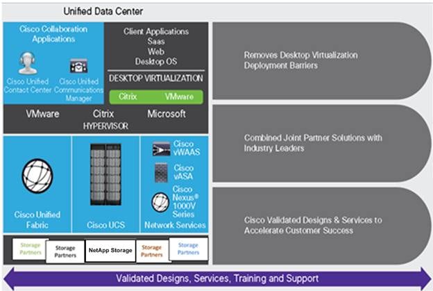
Cisco Desktop Virtualization Solutions: Data Center
Today’s IT departments are facing a rapidly evolving workplace environment. The workforce is becoming increasingly diverse and geographically dispersed, including offshore contractors, distributed call center operations, knowledge and task workers, partners, consultants, and executives connecting from locations around the world at all times.
This workforce is also increasingly mobile, conducting business in traditional offices, conference rooms across the enterprise campus, home offices, on the road, in hotels, and at the local coffee shop. This workforce wants to use a growing array of client computing and mobile devices that they can choose based on personal preference. These trends are increasing pressure on IT to ensure the protection of corporate data and prevent data leakage or loss through any combination of user, endpoint device, and desktop access scenarios (Figure 1).
These challenges are compounded by desktop refresh cycles to accommodate aging PCs and bounded local storage and migration to new operating systems, specifically Microsoft Windows 10 and productivity tools, specifically Microsoft Office 2016.
Figure 1. Cisco Data Center Partner Collaboration
Some of the key drivers for desktop virtualization are increased data security and reduced TCO through increased control and reduced management costs.
Cisco Desktop Virtualization Focus
Cisco focuses on three key elements to deliver the best desktop virtualization data center infrastructure: simplification, security, and scalability. The software combined with platform modularity provides a simplified, secure, and scalable desktop virtualization platform.
Simplified
Cisco UCS provides a radical new approach to industry-standard computing and provides the core of the data center infrastructure for desktop virtualization. Among the many features and benefits of Cisco UCS are the drastic reduction in the number of servers needed and in the number of cables used per server, and the capability to rapidly deploy or reprovision servers through Cisco UCS service profiles. With fewer servers and cables to manage and with streamlined server and virtual desktop provisioning, operations are significantly simplified. Thousands of desktops can be provisioned in minutes with Cisco UCS Manager service profiles and Cisco storage partners’ storage-based cloning. This approach accelerates the time to productivity for end users, improves business agility, and allows IT resources to be allocated to other tasks.
Cisco UCS Manager (UCSM) automates many mundane, error-prone data center operations such as configuration and provisioning of server, network, and storage access infrastructure. In addition, Cisco UCS B-Series Blade Servers and C-Series Rack Servers with large memory footprints enable high desktop density that helps reduce server infrastructure requirements.
Simplification also leads to more successful desktop virtualization implementation. Cisco and its technology partners like VMware Technologies and NetApp have developed integrated, validated architectures, including predefined converged architecture infrastructure packages such as FlexPod. Cisco Desktop Virtualization Solutions have been tested with VMware vSphere, VMware Horizon, Citrix Virtual Apps and Desktops.
Secure
Although virtual desktops are inherently more secure than their physical predecessors, they introduce new security challenges. Mission-critical web and application servers using a common infrastructure such as virtual desktops are now at a higher risk for security threats. Inter–virtual machine traffic now poses an important security consideration that IT managers need to address, especially in dynamic environments in which virtual machines, using VMware vMotion, move across the server infrastructure.
Desktop virtualization, therefore, significantly increases the need for the virtual machine–level awareness of policy and security, especially given the dynamic and fluid nature of virtual machine mobility across an extended computing infrastructure. The ease with which new virtual desktops can proliferate magnifies the importance of a virtualization-aware network and security infrastructure. Cisco data center infrastructure (Cisco UCS and Cisco Nexus Family solutions) for desktop virtualization provides strong data center, network, and desktop security, with comprehensive security from the desktop to the hypervisor. Security is enhanced with segmentation of virtual desktops, virtual machine–aware policies and administration, and network security across the LAN and WAN infrastructure.
Scalable
The growth of a desktop virtualization solution is all but inevitable, so a solution must be able to scale, and scale predictably, with that growth. The Cisco Desktop Virtualization Solutions built on FlexPod Datacenter infrastructure supports high virtual-desktop density (desktops per server), and additional servers and storage scale with near-linear performance. FlexPod Datacenter provides a flexible platform for growth and improves business agility. Cisco UCS Manager service profiles allow on-demand desktop provisioning and make it just as easy to deploy dozens of desktops as it is to deploy thousands of desktops.
Cisco UCS servers provide near-linear performance and scale. Cisco UCS implements the patented Cisco Extended Memory Technology to offer large memory footprints with fewer sockets (with scalability to up to 1 terabyte (TB) of memory with 2- and 4-socket servers). Using unified fabric technology as a building block, Cisco UCS server aggregate bandwidth can scale to up to 80 Gbps per server, and the northbound Cisco UCS fabric interconnect can output 2 terabits per second (Tbps) at line rate, helping prevent desktop virtualization I/O and memory bottlenecks. Cisco UCS, with its high-performance, low-latency unified fabric-based networking architecture, supports high volumes of virtual desktop traffic, including high-resolution video and communications traffic. In addition, Cisco storage partners NetApp help maintain data availability and optimal performance during boot and login storms as part of the Cisco Desktop Virtualization Solutions. Recent Cisco Validated Designs for End User Computing based on FlexPod solutions have demonstrated scalability and performance, with up to 6000 desktops up and running in less than 30 minutes.
FlexPod Datacenter provides an excellent platform for growth, with transparent scaling of server, network, and storage resources to support desktop virtualization, data center applications, and cloud computing.
Savings and Success
The simplified, secure, scalable Cisco data center infrastructure for desktop virtualization solutions saves time and money compared to alternative approaches. Cisco UCS enables faster payback and ongoing savings (better ROI and lower TCO) and provides the industry’s greatest virtual desktop density per server, reducing both capital expenditures (CapEx) and operating expenses (OpEx). The Cisco UCS architecture and Cisco Unified Fabric also enables much lower network infrastructure costs, with fewer cables per server and fewer ports required. In addition, storage tiering and deduplication technologies decrease storage costs, reducing desktop storage needs by up to 50 percent.
The simplified deployment of Cisco UCS for desktop virtualization accelerates the time to productivity and enhances business agility. IT staff and end users are more productive more quickly, and the business can respond to new opportunities quickly by deploying virtual desktops whenever and wherever they are needed. The high-performance Cisco systems and network deliver a near-native end-user experience, allowing users to be productive anytime and anywhere.
The ultimate measure of desktop virtualization for any organization is its efficiency and effectiveness in both the near term and the long term. The Cisco Desktop Virtualization Solutions are very efficient, allowing rapid deployment, requiring fewer devices and cables, and reducing costs. The solutions are also very effective, providing the services that end users need on their devices of choice while improving IT operations, control, and data security. Success is bolstered through Cisco’s best-in-class partnerships with leaders in virtualization and storage, and through tested and validated designs and services to help customers throughout the solution lifecycle. Long-term success is enabled through the use of Cisco’s scalable, flexible, and secure architecture for the platform for desktop virtualization.
Figure 2 illustrates the physical architecture.
Figure 2. Physical Architecture
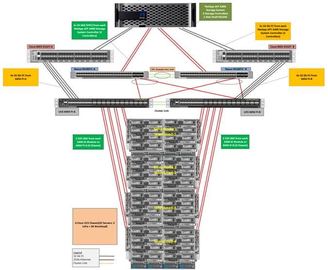
The reference hardware configuration includes:
● Two Cisco Nexus 93180YC-FX switches
● Two Cisco MDS 9132T 32GB Fibre Channel switches
● Two Cisco UCS 6454 Fabric Interconnects
● Four Cisco UCS 5108 Blade Chassis
● Two Cisco UCS B200 M5 Blade Servers (2 Infra Server hosting Infrastructure VMs)
● Thirty Cisco UCS B200 M5 Blade Servers (for workload)
● One NetApp AFF A400 Storage System
● Two NetApp NS224 Disk Shelves
For desktop virtualization, the deployment includes Citrix Virtual Apps & Desktops 1912 LTSR running on VMware vSphere 7.01.
The design is intended to provide a large-scale building block for Citrix Virtual Apps & Desktops workloads consisting of RDS Windows Server 2019 hosted shared desktop sessions and Windows 10 non-persistent and persistent hosted desktops in the following:
● 6000 Random Hosted Shared Windows 2019 user sessions with office 2016 (PVS)
● 5000 Random Pooled Windows 10 Desktops with office 2016 (PVS)
● 5000 Static Full Copy Windows 10 Desktops with office 2016 (MCS)
The data provided in this document will allow our customers to adjust the mix of HSD and HSD desktops to suit their environment. For example, additional blade servers and chassis can be deployed to increase compute capacity, additional disk shelves can be deployed to improve I/O capability and throughput, and special hardware or software features can be added to introduce new features. This document guides you through the detailed steps for deploying the base architecture. This procedure explains everything from physical cabling to network, compute, and storage device configurations.
This Cisco Validated Design provides details for deploying a fully redundant, highly available 6000 seats mixed workload virtual desktop solution with VMware on a FlexPod Datacenter architecture. Configuration guidelines are provided that refer the reader to which redundant component is being configured with each step. For example, storage controller 01and storage controller 02 are used to identify the two AFF A400 storage controllers that are provisioned with this document, Cisco Nexus A or Cisco Nexus B identifies the pair of Cisco Nexus switches that are configured, and Cisco MDS A or Cisco MDS B identifies the pair of Cisco MDS switches that are configured.
The Cisco UCS 6454 Fabric Interconnects are similarly configured. Additionally, this document details the steps for provisioning multiple Cisco UCS hosts, and these are identified sequentially: VM-Host-Infra-01, VM-Host-Infra-02, VM-Host-RDSH-01, VM-Host-VDI-01 and so on. Finally, to indicate that you should include information pertinent to your environment in a given step, <text> appears as part of the command structure.
This section describes the components used in the solution outlined in this study.
FlexPod is a defined set of hardware and software that serves as an integrated foundation for both virtualized and non-virtualized solutions. VMware vSphere® built on FlexPod includes NetApp AFF storage, Cisco Nexus® networking, Cisco MDS storage networking, the Cisco Unified Computing System (Cisco UCS®), and VMware vSphere software in a single package. The design is flexible enough that the networking, computing, and storage can fit in one data center rack or be deployed according to a customer's data center design. Port density enables the networking components to accommodate multiple configurations of this kind.
One benefit of the FlexPod architecture is the ability to customize or "flex" the environment to suit a customer's requirements. A FlexPod can easily be scaled as requirements and demand change. The unit can be scaled both up (adding resources to a FlexPod unit) and out (adding more FlexPod units). The reference architecture detailed in this document highlights the resiliency, cost benefit, and ease of deployment of a Fibre Channel and IP-based storage solution. A storage system capable of serving multiple protocols across a single interface allows for customer choice and investment protection because it truly is a wire-once architecture.
Figure 3. FlexPod Component Families
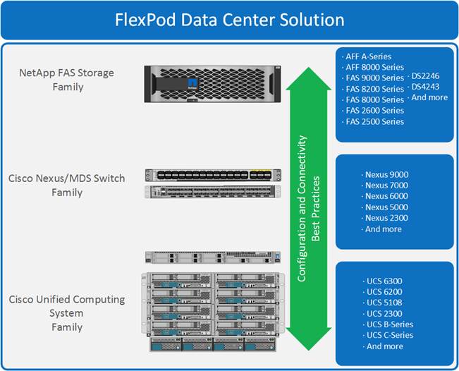
These components are connected and configured according to the best practices of both Cisco and NetApp to provide an ideal platform for running a variety of enterprise workloads with confidence. FlexPod can scale up for greater performance and capacity (adding compute, network, or storage resources individually as needed), or it can scale out for environments that require multiple consistent deployments (such as rolling out of additional FlexPod stacks). The reference architecture covered in this document leverages Cisco Nexus 9000 for the network switching element and pulls in the Cisco MDS 9000 for the SAN switching component.
One of the key benefits of FlexPod is its ability to maintain consistency during scale. Each of the component families shown (Cisco UCS, Cisco Nexus, and NetApp AFF) offers platform and resource options to scale the infrastructure up or down, while supporting the same features and functionality that are required under the configuration and connectivity best practices of FlexPod.
The following lists the benefits of FlexPod:
● Consistent Performance and Scalability
◦ Consistent sub-millisecond latency with 100% flash storage
◦ Consolidate 100’s of enterprise-class applications in a single rack
◦ Scales easily, without disruption
◦ Continuous growth through multiple FlexPod CI deployments
● Operational Simplicity
◦ Fully tested, validated, and documented for rapid deployment
◦ Reduced management complexity
◦ Auto-aligned 512B architecture removes storage alignment issues
◦ No storage tuning or tiers necessary
● Lowest TCO
◦ Dramatic savings in power, cooling, and space with 100 percent Flash
◦ Industry leading data reduction
● Enterprise-Grade Resiliency
◦ Highly available architecture with no single point of failure
◦ Nondisruptive operations with no downtime
◦ Upgrade and expand without downtime or performance loss
◦ Native data protection: snapshots and replication
◦ Suitable for even large resource-intensive workloads such as real-time analytics or heavy transactional databases
This section describes the components used in the solution outlined in this solution.
Cisco Unified Computing System
Cisco UCS Manager (UCSM) provides unified, embedded management of all software and hardware components of the Cisco Unified Computing System™ (Cisco UCS) through an intuitive GUI, a CLI, and an XML API. The manager provides a unified management domain with centralized management capabilities and can control multiple chassis and thousands of virtual machines.
Cisco UCS is a next-generation data center platform that unites computing, networking, and storage access. The platform, optimized for virtual environments, is designed using open industry-standard technologies and aims to reduce total cost of ownership (TCO) and increase business agility. The system integrates a low-latency; lossless 25 Gigabit Ethernet unified network fabric with enterprise-class, x86-architecture servers. It is an integrated, scalable, multi-chassis platform in which all resources participate in a unified management domain.
Cisco Unified Computing System Components
The main components of Cisco UCS are:
● Compute: The system is based on an entirely new class of computing system that incorporates blade servers based on Intel® Xeon® Scalable Family processors.
● Network: The system is integrated on a low-latency, lossless, 25-Gbe unified network fabric. This network foundation consolidates LANs, SANs, and high-performance computing (HPC) networks, which are separate networks today. The unified fabric lowers costs by reducing the number of network adapters, switches, and cables needed, and by decreasing the power and cooling requirements.
● Virtualization: The system unleashes the full potential of virtualization by enhancing the scalability, performance, and operational control of virtual environments. Cisco security, policy enforcement, and diagnostic features are now extended into virtualized environments to better support changing business and IT requirements.
● Storage access: The system provides consolidated access to local storage, SAN storage, and network-attached storage (NAS) over the unified fabric. With storage access unified, Cisco UCS can access storage over Ethernet, Fibre Channel, Fibre Channel over Ethernet (FCoE), and Small Computer System Interface over IP (iSCSI) protocols. This capability provides customers with choice for storage access and investment protection. In addition, server administrators can pre-assign storage-access policies for system connectivity to storage resources, simplifying storage connectivity and management and helping increase productivity.
● Management: Cisco UCS uniquely integrates all system components, enabling the entire solution to be managed as a single entity by Cisco UCS Manager. Cisco UCS Manager has an intuitive GUI, a CLI, and a robust API for managing all system configuration processes and operations.
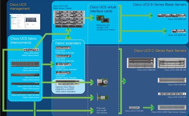
Figure 4. Cisco Data Center Overview
Cisco UCS is designed to deliver:
● Reduced TCO and increased business agility
● Increased IT staff productivity through just-in-time provisioning and mobility support
● A cohesive, integrated system that unifies the technology in the data center; the system is managed, serviced, and tested as a whole
● Scalability through a design for hundreds of discrete servers and thousands of virtual machines and the capability to scale I/O bandwidth to match demand
● Industry standards supported by a partner ecosystem of industry leaders
Cisco UCS Manager provides unified, embedded management of all software and hardware components of the Cisco Unified Computing System across multiple chassis, rack servers, and thousands of virtual machines. Cisco UCS Manager manages Cisco UCS as a single entity through an intuitive GUI, a CLI, or an XML API for comprehensive access to all Cisco UCS Manager Functions.
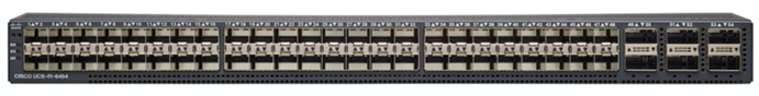
The Cisco UCS 6400 Series Fabric Interconnects are a core part of the Cisco Unified Computing System, providing both network connectivity and management capabilities for the system. The Cisco UCS 6400 Series offer line-rate, low-latency, lossless 10/25/40/100 Gigabit Ethernet, Fibre Channel over Ethernet (FCoE), and Fibre Channel functions.
The Cisco UCS 6400 Series provide the management and communication backbone for the Cisco UCS B-Series Blade Servers, Cisco UCS 5108 B-Series Server Chassis, Cisco UCS Managed C-Series Rack Servers, and Cisco UCS S-Series Storage Servers. All servers attached to a Cisco UCS 6400 Series Fabric Interconnect become part of a single, highly available management domain. In addition, by supporting a unified fabric, Cisco UCS 6400 Series Fabric Interconnect provides both the LAN and SAN connectivity for all servers within its domain.
From a networking perspective, the Cisco UCS 6400 Series use a cut-through architecture, supporting deterministic, low-latency, line-rate 10/25/40/100 Gigabit Ethernet ports, switching capacity of 3.82 Tbps for the 6454, 7.42 Tbps for the 64108, and 200 Gbe bandwidth between the Fabric Interconnect 6400 series and the IOM 2408 per 5108 blade chassis, independent of packet size and enabled services. The product family supports Cisco low-latency, lossless 10/25/40/100 Gigabit Ethernet unified network fabric capabilities, which increase the reliability, efficiency, and scalability of Ethernet networks. The fabric interconnect supports multiple traffic classes over a lossless Ethernet fabric from the server through the fabric interconnect. Significant TCO savings come from an FCoE-optimized server design in which Network Interface Cards (NICs), Host Bus Adapters (HBAs), cables, and switches can be consolidated.
Figure 5. Cisco UCS 6400 Series Fabric Interconnect – 6454 Front View
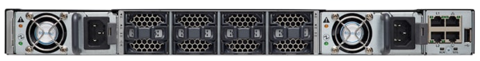
Figure 6. Cisco UCS 6400 Series Fabric Interconnect – 6454 Rear view
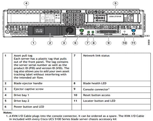
Cisco UCS B200 M5 Blade Server
The Cisco UCS B200 M5 Blade Server (Figure 7 and Figure 8) is a density-optimized, half-width blade server that supports two CPU sockets for Intel Xeon processor 6230 Gold series CPUs and up to 24 DDR4 DIMMs. It supports one modular LAN-on-motherboard (LOM) dedicated slot for a Cisco virtual interface card (VIC) and one mezzanine adapter. In additions, the Cisco UCS B200 M5 supports an optional storage module that accommodates up to two SAS or SATA hard disk drives (HDDs) or solid-state disk (SSD) drives. You can install up to eight Cisco UCS B200 M5 servers in a chassis, mixing them with other models of Cisco UCS blade servers in the chassis if desired.
Figure 7. Cisco UCS B200 M5 Front View
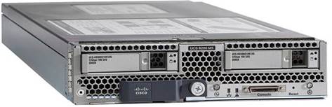
Figure 8. Cisco UCS B200 M5 Back View
Cisco UCS combines Cisco UCS B-Series Blade Servers and C-Series Rack Servers with networking and storage access into a single converged system with simplified management, greater cost efficiency and agility, and increased visibility and control. The Cisco UCS B200 M5 Blade Server is one of the newest servers in the Cisco UCS portfolio.
The Cisco UCS B200 M5 delivers performance, flexibility, and optimization for data centers and remote sites. This enterprise-class server offers market-leading performance, versatility, and density without compromise for workloads ranging from web infrastructure to distributed databases. The Cisco UCS B200 M5 can quickly deploy stateless physical and virtual workloads with the programmable ease of use of the Cisco UCS Manager software and simplified server access with Cisco® Single Connect technology. Based on the Intel Xeon® processor Gold 6230 product family, it offers up to 3 TB of memory using 128GB DIMMs, up to two disk drives, and up to 320 GB of I/O throughput. The Cisco UCS B200 M5 offers exceptional levels of performance, flexibility, and I/O throughput to run your most demanding applications.
In addition, Cisco UCS has the architectural advantage of not having to power and cool excess switches, NICs, and HBAs in each blade server chassis. With a larger power budget per blade server, it provides uncompromised expandability and capabilities, as in the new Cisco UCS B200 M5 server with its leading memory-slot capacity and drive capacity.
The Cisco UCS B200 M5 provides:
● Latest Intel® Xeon® Scalable processors with up to 28 cores per socket
● Up to 24 DDR4 DIMMs for improved performance
● Intel 3D XPoint-ready support, with built-in support for next-generation nonvolatile memory technology
● Two GPUs
● Two Small-Form-Factor (SFF) drives
● Two Secure Digital (SD) cards or M.2 SATA drives
● Up to 80 Gbe of I/O throughput
The Cisco UCS B200 M5 server is a half-width blade. Up to eight servers can reside in the 6-Rack-Unit (6RU) Cisco UCS 5108 Blade Server Chassis, offering one of the highest densities of servers per rack unit of blade chassis in the industry. You can configure the Cisco UCS B200 M5 to meet your local storage requirements without having to buy, power, and cool components that you do not need.
The Cisco UCS B200 M5 provides these main features:
● Up to two Intel Xeon Scalable CPUs with up to 28 cores per CPU
● 24 DIMM slots for industry-standard DDR4 memory at speeds up to 2933 MHz, with up to 3 TB of total memory when using 128-GB DIMMs
● Modular LAN On Motherboard (mLOM) card with Cisco UCS Virtual Interface Card (VIC) 1440 or 1340, a 2-port, 40 Gigabit Ethernet, Fibre Channel over Ethernet (FCoE)–capable mLOM mezzanine adapter
● Optional rear mezzanine VIC with two 40-Gbe unified I/O ports or two sets of 4 x 10-Gbe unified I/O ports, delivering 80 Gbe to the server; adapts to either 10- or 40-Gbe fabric connections
● Two optional, hot-pluggable, hard-disk drives (HDDs), solid-state drives (SSDs), or NVMe 2.5-inch drives with a choice of enterprise-class RAID or pass-through controllers
● Cisco FlexStorage local drive storage subsystem, which provides flexible boot and local storage capabilities and allows you to boot from dual, mirrored SD cards
● Support for up to two optional GPUs
● Support for up to one rear storage mezzanine card
● Support for one 16-GB internal flash USB drive
For more information about Cisco UCS B200 M5, see the Cisco UCS B200 M5 Blade Server Specsheet.
Table 1. Ordering Information
| Part Number |
Description |
| UCSB-B200-M5 |
UCS B200 M5 Blade w/o CPU, mem, HDD, mezz |
| UCSB-B200-M5-U |
UCS B200 M5 Blade w/o CPU, mem, HDD, mezz (UPG) |
| UCSB-B200-M5-CH |
UCS B200 M5 Blade w/o CPU, mem, HDD, mezz, Drive bays, HS |
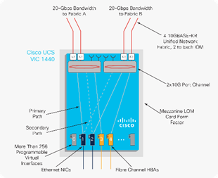
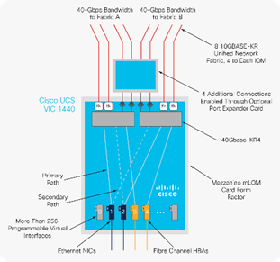
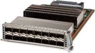
Cisco UCS VIC1440 Converged Network Adapter
The Cisco UCS VIC 1440 (Figure 9) is a single-port 40-Gbe or 4x10-Gbe Ethernet/FCoE capable modular LAN On Motherboard (mLOM) designed exclusively for the M5 generation of Cisco UCS B-Series Blade Servers. When used in combination with an optional port expander, the Cisco UCS VIC 1440 capabilities are enabled for two ports of 40-Gbe Ethernet. The Cisco UCS VIC 1440 enables a policy-based, stateless, agile server infrastructure that can present to the host PCIe standards-compliant interfaces that can be dynamically configured as either NICs or HBAs.
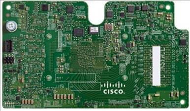
Figure 10 illustrates the Cisco UCS VIC 1440 deployed in the Cisco UCS B-Series B200 M5 Blade Servers.
Figure 10. Cisco UCS VIC 1440 Deployed in the Cisco UCS B-Series B200 M5 Blade Servers
Cisco Nexus 93180YC-FX Switches
The 93180YC-EX Switch provides a flexible line-rate Layer 2 and Layer 3 feature set in a compact form factor. Designed with Cisco Cloud Scale technology, it supports highly scalable cloud architectures. With the option to operate in Cisco NX-OS or Application Centric Infrastructure (ACI) mode, it can be deployed across enterprise, service provider, and Web 2.0 data centers.
● Architectural Flexibility
◦ Includes top-of-rack or middle-of-row fiber-based server access connectivity for traditional and leaf-spine architectures
◦ Leaf node support for Cisco ACI architecture is provided in the roadmap
◦ Increase scale and simplify management through Cisco Nexus 2000 Fabric Extender support
● Feature Rich
◦ Enhanced Cisco NX-OS Software is designed for performance, resiliency, scalability, manageability, and programmability
◦ ACI-ready infrastructure helps users take advantage of automated policy-based systems management
◦ Virtual Extensible LAN (VXLAN) routing provides network services
◦ Rich traffic flow telemetry with line-rate data collection
◦ Real-time buffer utilization per port and per queue, for monitoring traffic micro-bursts and application traffic patterns
● Highly Available and Efficient Design
◦ High-density, non-blocking architecture
◦ Easily deployed into either a hot-aisle and cold-aisle configuration
◦ Redundant, hot-swappable power supplies and fan trays
● Simplified Operations
◦ Power-On Auto Provisioning (POAP) support allows for simplified software upgrades and configuration file installation
◦ An intelligent API offers switch management through remote procedure calls (RPCs, JSON, or XML) over a HTTP/HTTPS infrastructure
◦ Python Scripting for programmatic access to the switch command-line interface (CLI)
◦ Hot and cold patching, and online diagnostics
● Investment Protection
A Cisco 40 Gbe bidirectional transceiver allows reuse of an existing 10 Gigabit Ethernet multimode cabling plant for 40 Gigabit Ethernet Support for 1 Gbe and 10 Gbe access connectivity for data centers migrating access switching infrastructure to faster speed. The following is supported:
◦ 1.8 Tbps of bandwidth in a 1 RU form factor
◦ 48 fixed 1/10/25-Gbe SFP+ ports
◦ 6 fixed 40/100-Gbe QSFP+ for uplink connectivity
◦ Latency of less than 2 microseconds
◦ Front-to-back or back-to-front airflow configurations
◦ 1+1 redundant hot-swappable 80 Plus Platinum-certified power supplies
◦ Hot swappable 3+1 redundant fan trays
Figure 11. Cisco Nexus 93180YC-EX Switch
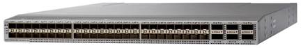
Cisco MDS 9132T 32-Gb Fiber Channel Switch
The next-generation Cisco® MDS 9132T 32-Gb 32-Port Fibre Channel Switch (Figure 15) provides high-speed Fibre Channel connectivity from the server rack to the SAN core. It empowers small, midsize, and large enterprises that are rapidly deploying cloud-scale applications using extremely dense virtualized servers, providing the dual benefits of greater bandwidth and consolidation.
Small-scale SAN architectures can be built from the foundation using this low-cost, low-power, non-blocking, line-rate, and low-latency, bi-directional airflow capable, fixed standalone SAN switch connecting both storage and host ports.
Medium-size to large-scale SAN architectures built with SAN core directors can expand 32-Gb connectivity to the server rack using these switches either in switch mode or Network Port Virtualization (NPV) mode.
Additionally, investing in this switch for the lower-speed (4- or 8- or 16-Gb) server rack gives you the option to upgrade to 32-Gb server connectivity in the future using the 32-Gb Host Bus Adapter (HBA) that are available today. The Cisco® MDS 9132T 32-Gb 32-Port Fibre Channel switch also provides unmatched flexibility through a unique port expansion module (Figure 12) that provides a robust cost-effective, field swappable, port upgrade option.
This switch also offers state-of-the-art SAN analytics and telemetry capabilities that have been built into this next-generation hardware platform. This new state-of-the-art technology couples the next-generation port ASIC with a fully dedicated Network Processing Unit designed to complete analytics calculations in real time. The telemetry data extracted from the inspection of the frame headers are calculated on board (within the switch) and, using an industry-leading open format, can be streamed to any analytics-visualization platform. This switch also includes a dedicated 10/100/1000BASE-T telemetry port to maximize data delivery to any telemetry receiver including Cisco Data Center Network Manager.
Figure 12. Cisco 9132T 32-Gb MDS Fibre Channel Switch
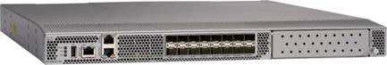
Figure 13. Cisco MDS 9132T 32-Gb 16-Port Fibre Channel Port Expansion Module
● Features
◦ High performance: MDS 9132T architecture, with chip-integrated nonblocking arbitration, provides consistent 32-Gb low-latency performance across all traffic conditions for every Fibre Channel port on the switch.
◦ Capital Expenditure (CapEx) savings: The 32-Gb ports allow users to deploy them on existing 16- or 8-Gb transceivers, reducing initial CapEx with an option to upgrade to 32-Gb transceivers and adapters in the future.
◦ High availability: MDS 9132T switches continue to provide the same outstanding availability and reliability for the previous-generation Cisco MDS 9000 Family switches by providing optional redundancy on all major components such for the power supply and fan. Dual power supplies also facilitate redundant power grids.
◦ Pay-as-you-grow: The MDS 9132T Fibre Channel switch provides an option to deploy as few as eight 32-Gb Fibre Channel ports in the entry-level variant, which can grow by 8 ports to 16 ports, and thereafter with a port expansion module with sixteen 32-Gb ports, to up to 32 ports. This approach results in lower initial investment and power consumption for entry-level configurations of up to 16 ports compared to a fully loaded switch. Upgrading through an expansion module also reduces the overhead of managing multiple instances of port activation licenses on the switch. This unique combination of port upgrade options allow four possible configurations of 8 ports, 16 ports, 24 ports and 32 ports.
◦ Next-generation Application-Specific Integrated Circuit (ASIC): The MDS 9132T Fibre Channel switch is powered by the same high-performance 32-Gb Cisco ASIC with an integrated network processor that powers the Cisco MDS 9700 48-Port 32-Gb Fibre Channel Switching Module. Among all the advanced features that this ASIC enables, one of the most notable is inspection of Fibre Channel and Small Computer System Interface (SCSI) headers at wire speed on every flow in the smallest form-factor Fibre Channel switch without the need for any external taps or appliances. The recorded flows can be analyzed on the switch and also exported using a dedicated 10/100/1000BASE-T port for telemetry and analytics purposes.
◦ Intelligent network services: Slow-drain detection and isolation, VSAN technology, Access Control Lists (ACLs) for hardware-based intelligent frame processing, smartzoning and fabric wide Quality of Service (QoS) enable migration from SAN islands to enterprise wide storage networks. Traffic encryption is optionally available to meet stringent security requirements.
◦ Sophisticated diagnostics: The MDS 9132T provides intelligent diagnostics tools such as Inter-Switch Link (ISL) diagnostics, read diagnostic parameters, protocol decoding, network analysis tools, and integrated Cisco Call Home capability for greater reliability, faster problem resolution, and reduced service costs.
◦ Virtual machine awareness: The MDS 9132T provides visibility into all virtual machines logged into the fabric. This feature is available through HBAs capable of priority tagging the Virtual Machine Identifier (VMID) on every FC frame. Virtual machine awareness can be extended to intelligent fabric services such as analytics[1] to visualize performance of every flow originating from each virtual machine in the fabric.
◦ Programmable fabric: The MDS 9132T provides powerful Representational State Transfer (REST) and Cisco NX-API capabilities to enable flexible and rapid programming of utilities for the SAN as well as polling point-in-time telemetry data from any external tool.
◦ Single-pane management: The MDS 9132T can be provisioned, managed, monitored, and troubleshot using Cisco Data Center Network Manager (DCNM), which currently manages the entire suite of Cisco data center products.
◦ Self-contained advanced anticounterfeiting technology: The MDS 9132T uses on-board hardware that protects the entire system from malicious attacks by securing access to critical components such for the bootloader, system image loader and Joint Test Action Group (JTAG) interface.
This Cisco Validated Design includes VMware vSphere ESXi 7.0.1 Update 1.
VMware vSphere 7.0
VMware provides virtualization software. VMware’s enterprise software hypervisors for servers are bare-metal hypervisors that run directly on server hardware without requiring an additional underlying operating system. VMware vCenter Server for vSphere provides central management and complete control and visibility into clusters, hosts, virtual machines, storage, networking, and other critical elements of your virtual infrastructure.
vSphere 7 is the latest major vSphere release from VMware. vSphere 7 has been rearchitected with native Kubernetes to enable IT Admins to use vCenter Server® to operate Kubernetes clusters through namespaces. VMware vSphere with Tanzu allows IT Admins to operate with their existing skillset and deliver a self-service access to infrastructure for the Dev Ops teams; while providing observability and troubleshooting for Kubernetes workloads. vSphere 7 provides an enterprise platform for both traditional applications as well as modern applications – so customers and partners can deliver a developer-ready infrastructure, scale without compromise and simplify operations.
Deliver Developer-ready Infrastructure: IT teams can use existing vSphere environments to set up an Enterprise-grade Kubernetes infrastructure at a rapid pace (within one hour), while enabling enterprise-class governance, reliability, and security. After this one-time setup, vSphere with Tanzu enables a simple, fast, and self-service provisioning of Tanzu Kubernetes clusters within a few minutes1. Aligning DevOps teams and IT teams is critical to the success of modern application development; to bring efficiency, scale and security to Kubernetes deployments and operations. vSphere with Tanzu brings agile cloud operations to the IT admin to enable this transition into the role of Cloud Admin or SRE by delivering agility in day to day IT operations related to Kubernetes infrastructure.
Scale Without Compromise: vSphere can scale your infrastructure to meet the demands of high-performance applications and memory intensive databases including SAP HANA and Epic Caché Operational Database to name a few. With vSphere 7, a vSphere cluster can now support 50% more hosts compared to previous releases.
Simplify Operations: Simplified operations are delivered through key capabilities of vSphere 7 including elastic AI/ML infrastructure for sharing resources, simplified lifecycle management and intrinsic security across your hybrid cloud infrastructure.
Key Features and Capabilities
The following are the key feature and capabilities:
● TKG Service2: Run the Tanzu Kubernetes Grid Service directly on vSphere to simplify operation of Kubernetes on-premises by putting cloud native constructs at the IT Admin’s fingertips. TKG allows IT admins to manage consistent, compliant, and conformant Kubernetes, while providing developers self-service access to infrastructure. vSphere with Tanzu enables a simple, fast, and self-service provisioning of Tanzu Kubernetes clusters within a few minutes1.
● Drop-in to Existing Infrastructure2: Quickly deploy Kubernetes workloads on existing infrastructure with enterprise-grade governance, reliability, and security. Leverage existing networking infrastructure (or BYO networking) using vSphere Distributed Switch's (VDS) centralized interface to configure, monitor and administer switching access for VMs and Kubernetes workloads. Deploy existing block and file storage infrastructure (BYO storage) for containerized workloads. Choose your own L4 load balancing solution using HAProxy (commercial support offered directly by HAProxy) for Tanzu Kubernetes clusters.
● Application focused management2: Kubernetes makes vSphere better by providing DevOps teams (Platform Operators and SREs) with self-service access to infrastructure through Kubernetes APIs. vSphere makes Kubernetes better by empowering IT admins to use vCenter Server skills/tools to operate modern applications, alongside VMs, using namespaces as a unit of management. This is referred to as ‘application focused management’. Using application focused management, IT admins can use vCenter Server to observe and troubleshoot Tanzu Kubernetes clusters alongside VMs, implement role-based access and allocate capacity to developer teams.
● Monster VMs: Deliver industry leading scale through Monster VMs designed for SAP HANA and Epic Cache Operational Database. Improve performance and scale for Monster VMs to support your large scale-up environments. Scale-up to 24TB memory and support up to 768 vCPUs through Monster VMs, leaving other hypervisor vendors far behind in the category. Speed-up the ESXi scheduler and co-scheduling logic for large VMs using selective latency sensitivity setting for workloads, removal of bottlenecks in vCPU sleep/wakeup paths and a reduced memory overhead.
● Cluster scale enhancements: Expand the number of hosts per cluster by 50% to support a total of 96 hosts per cluster, compared to previous releases.
● vLCM enhancements: Simplify software upgrades, patching and firmware updates for vSphere, vSAN and NSX-T with a single tool. vLCM will also monitor for desired image compliance continuously and enable simple remediation in the event of any compliance drift.
● vSphere Ideas®: Submit feature requests right from the vSphere Client UI, track the status of the feature requests and look at all the other feature requests submitted by other users to vote for them, through the Ideas portal.
● vCenter connect®: Manage on-premises and off-premises (cloud providers) vCenter Servers in a single interface using the any to any vCenter connect capability.
Citrix Virtual Apps & Desktops 1912 LTSR
Enterprise IT organizations are tasked with the challenge of provisioning Microsoft Windows apps and desktops while managing cost, centralizing control, and enforcing corporate security policy. Deploying Windows apps to users in any location, regardless of the device type and available network bandwidth, enables a mobile workforce that can improve productivity. With Citrix Virtual Apps & Desktops 1912 LTSR, IT can effectively control app and desktop provisioning while securing data assets and lowering capital and operating expenses.
The Citrix Virtual Apps & Desktops 1912 LTSR release offers these benefits:
● Comprehensive virtual desktop delivery for any use case. The Citrix Virtual Apps & Desktops 1912 LTSR release incorporates the full power of RDS, delivering full desktops or just applications to users. Administrators can deploy both RDS published applications and desktops (to maximize IT control at low cost) or personalized VDI desktops (with simplified image management) from the same management console. Citrix Virtual Apps & Desktops 1912 LTSR leverages common policies and cohesive tools to govern both infrastructure resources and user access.
● Simplified support and choice of BYO (Bring Your Own) devices. Citrix Virtual Apps & Desktops 1912 LTSR brings thousands of corporate Microsoft Windows-based applications to mobile devices with a native-touch experience and optimized performance. HDX technologies create a “high definition” user experience, even for graphics intensive design and engineering applications.
● Lower cost and complexity of application and desktop management. Citrix Virtual Apps & Desktops 1912 LTSR helps IT organizations take advantage of agile and cost-effective cloud offerings, allowing the virtualized infrastructure to flex and meet seasonal demands or the need for sudden capacity changes. IT organizations can deploy Citrix Virtual Apps & Desktops application and desktop workloads to private or public clouds.
● Protection of sensitive information through centralization. Citrix Virtual Apps & Desktops decreases the risk of corporate data loss, enabling access while securing intellectual property and centralizing applications since assets reside in the datacenter.
● Virtual Delivery Agent improvements. Universal print server and driver enhancements and support for the HDX 3D Pro graphics acceleration for Windows 10 are key additions in Citrix Virtual Apps & Desktops 1912 LTSR
● Improved high-definition user experience. Citrix Virtual Apps & Desktops 1912 LTSR continues the evolutionary display protocol leadership with enhanced Thinwire display remoting protocol and Framehawk support for HDX 3D Pro.
Citrix RDS and Citrix Virtual Apps & Desktops are application and desktop virtualization solutions built on a unified architecture so they're simple to manage and flexible enough to meet the needs of all your organization's users. RDS and Citrix Virtual Apps & Desktops have a common set of management tools that simplify and automate IT tasks. You use the same architecture and management tools to manage public, private, and hybrid cloud deployments as you do for on premises deployments.
Citrix RDS delivers:
● RDS published apps, also known as server-based hosted applications: These are applications hosted from Microsoft Windows servers to any type of device, including Windows PCs, Macs, smartphones, and tablets. Some RDS editions include technologies that further optimize the experience of using Windows applications on a mobile device by automatically translating native mobile-device display, navigation, and controls to Windows applications; enhancing performance over mobile networks; and enabling developers to optimize any custom Windows application for any mobile environment.
● RDS published desktops, also known as server-hosted desktops: These are inexpensive, locked-down Windows virtual desktops hosted from Windows server operating systems. They are well suited for users, such as call center employees, who perform a standard set of tasks.
● Virtual machine–hosted apps: These are applications hosted from machines running Windows desktop operating systems for applications that can’t be hosted in a server environment.
● Windows applications delivered with Microsoft App-V: These applications use the same management tools that you use for the rest of your RDS deployment.
● Citrix Virtual Apps & Desktops: Includes significant enhancements to help customers deliver Windows apps and desktops as mobile services while addressing management complexity and associated costs. Enhancements in this release include:
● Unified product architecture for RDS and Citrix Virtual Apps & Desktops: The FlexCast Management Architecture (FMA). This release supplies a single set of administrative interfaces to deliver both hosted-shared applications (RDS) and complete virtual desktops (VDI). Unlike earlier releases that separately provisioned Citrix RDS and Citrix Virtual Apps & Desktops farms, the Citrix Virtual Apps & Desktops 1912 LTSR release allows administrators to deploy a single infrastructure and use a consistent set of tools to manage mixed application and desktop workloads.
● Support for extending deployments to the cloud. This release provides the ability for hybrid cloud provisioning from Microsoft Azure, Amazon Web Services (AWS) or any Cloud Platform-powered public or private cloud. Cloud deployments are configured, managed, and monitored through the same administrative consoles as deployments on traditional on-premises infrastructure.
Citrix Virtual Apps & Desktops delivers:
● VDI desktops: These virtual desktops each run a Microsoft Windows desktop operating system rather than running in a shared, server-based environment. They can provide users with their own desktops that they can fully personalize.
● Hosted physical desktops: This solution is well suited for providing secure access powerful physical machines, such as blade servers, from within your data center.
● Remote PC access: This solution allows users to log in to their physical Windows PC from anywhere over a secure Citrix Virtual Apps & Desktops connection.
● Server VDI: This solution is designed to provide hosted desktops in multitenant, cloud environments.
● Capabilities that allow users to continue to use their virtual desktops: These capabilities let users continue to work while not connected to your network.
New and Enhanced Features
This section describes the new and enhanced features in this product release.
![]() Some Citrix Virtual Apps & Desktops editions include the features available in RDS.
Some Citrix Virtual Apps & Desktops editions include the features available in RDS.
Deployments that span widely-dispersed locations connected by a WAN can face challenges due to network latency and reliability. Configuring zones can help users in remote regions connect to local resources without forcing connections to traverse large segments of the WAN. Using zones allows effective Site management from a single Citrix Studio console, Citrix Director, and the Site database. This saves the costs of deploying, staffing, licensing, and maintaining additional Sites containing separate databases in remote locations.
Zones can be helpful in deployments of all sizes. You can use zones to keep applications and desktops closer to end users, which improves performance.
For more information, see the Zones article.
Improved Database Flow and Configuration
When you configure the databases during Site creation, you can now specify separate locations for the Site, Logging, and Monitoring databases. Later, you can specify different locations for all three databases. In previous releases, all three databases were created at the same address, and you could not specify a different address for the Site database later.
You can now add more Delivery Controllers when you create a Site, as well as later. In previous releases, you could add more Controllers only after you created the Site.
For more information, see the Databases and Controllers articles.
Configure application limits to help manage application use. For example, you can use application limits to manage the number of users accessing an application simultaneously. Similarly, application limits can be used to manage the number of simultaneous instances of resource-intensive applications, this can help maintain server performance and prevent deterioration in service.
For more information, see the Manage applications article.
Multiple Notifications before Machine Updates or Scheduled Restarts
You can now choose to repeat a notification message that is sent to affected machines before the following types of actions begin:
● Updating machines in a Machine Catalog using a new master image
● Restarting machines in a Delivery Group according to a configured schedule
If you indicate that the first message should be sent to each affected machine 15 minutes before the update or restart begins, you can also specify that the message be repeated every five minutes until the update/restart begins.
For more information, see the Manage Machine Catalogs and Manage machines in Delivery Groups articles.
API Support for Managing Session Roaming
By default, sessions roam between client devices with the user. When the user launches a session and then moves to another device, the same session is used, and applications are available on both devices. The applications follow, regardless of the device or whether current sessions exist. Similarly, printers and other resources assigned to the application follow.
![]() You can now use the PowerShell SDK to tailor session roaming. This was an experimental feature in the previous release.
You can now use the PowerShell SDK to tailor session roaming. This was an experimental feature in the previous release.
For more information, see the Sessions article.
API Support for Provisioning VMs from Hypervisor Templates
When using the PowerShell SDK to create or update a Machine Catalog, you can now select a template from other hypervisor connections. This is in addition to the currently-available choices of VM images and snapshots.
Support for New and Additional Platforms
See the System requirements article for full support information. Information about support for third-party product versions is updated periodically.
When installing a Controller, Microsoft SQL Server Express LocalDB 2017 with Cumulative Update 16 is installed for use with the Local Host Cache feature. This installation is separate from the default SQL Server Express installation for the site database. (When upgrading a Controller, the existing Microsoft SQL Server Express LocalDB version is not upgraded. If you want to upgrade the LocalDB version, follow the guidance in Database actions.).
Installing the Microsoft Visual C++ 2017 Runtime on a machine that has the Microsoft Visual C++ 2015 Runtime installed can result in automatic removal of the Visual C++ 2015 Runtime. This is as designed.
If you’ve already installed Citrix components that automatically install the Visual C++ 2015 Runtime, those components will continue to operate correctly with the Visual C++ 2017 version.
You can install Studio or VDAs for Windows Desktop OS on machines running Windows 10.
You can create connections to Microsoft Azure virtualization resources.
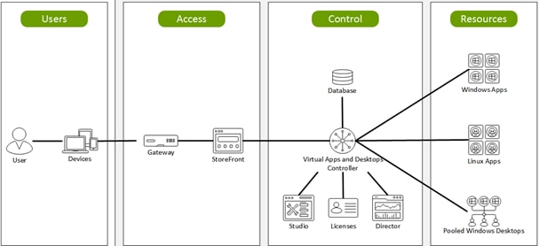
Figure 14. Logical Architecture of Citrix Virtual Apps & Desktops
Citrix Provisioning Services 1912 LTSR
Most enterprises struggle to keep up with the proliferation and management of computers in their environments. Each computer, whether it is a desktop PC, a server in a data center, or a kiosk-type device, must be managed as an individual entity. The benefits of distributed processing come at the cost of distributed management. It costs time and money to set up, update, support, and ultimately decommission each computer. The initial cost of the machine is often dwarfed by operating costs.
Citrix PVS takes a very different approach from traditional imaging solutions by fundamentally changing the relationship between hardware and the software that runs on it. By streaming a single shared disk image (vDisk) rather than copying images to individual machines, PVS enables organizations to reduce the number of disk images that they manage, even for the number of machines continues to grow, simultaneously providing the efficiency of centralized management and the benefits of distributed processing.
In addition, because machines are streaming disk data dynamically and in real time from a single shared image, machine image consistency is essentially ensured. At the same time, the configuration, applications, and even the OS of large pools of machines can be completed changed in the time it takes the machines to reboot.
Using PVS, any vDisk can be configured in standard-image mode. A vDisk in standard-image mode allows many computers to boot from it simultaneously, greatly reducing the number of images that must be maintained and the amount of storage that is required. The vDisk is in read-only format, and the image cannot be changed by target devices.
Benefits for Citrix RDS and Other Server Farm Administrators
If you manage a pool of servers that work as a farm, such as Citrix RDS servers or web servers, maintaining a uniform patch level on your servers can be difficult and time consuming. With traditional imaging solutions, you start with a clean golden master image, but as soon as a server is built with the master image, you must patch that individual server along with all the other individual servers. Rolling out patches to individual servers in your farm is not only inefficient, but the results can also be unreliable. Patches often fail on an individual server, and you may not realize you have a problem until users start complaining or the server has an outage. After that happens, getting the server resynchronized with the rest of the farm can be challenging, and sometimes a full reimaging of the machine is required.
With Citrix PVS, patch management for server farms is simple and reliable. You start by managing your golden image, and you continue to manage that single golden image. All patching is performed in one place and then streamed to your servers when they boot. Server build consistency is assured because all your servers use a single shared copy of the disk image. If a server becomes corrupted, simply reboot it, and it is instantly back to the known good state of your master image. Upgrades are extremely fast to implement. After you have your updated image ready for production, you simply assign the new image version to the servers and reboot them. You can deploy the new image to any number of servers in the time it takes them to reboot. Just as important, rollback can be performed in the same way, so problems with new images do not need to take your servers or your users out of commission for an extended period of time.
Benefits for Desktop Administrators
Because Citrix PVS is part of Citrix Virtual Apps & Desktops, desktop administrators can use PVS’s streaming technology to simplify, consolidate, and reduce the costs of both physical and virtual desktop delivery. Many organizations are beginning to explore desktop virtualization. Although virtualization addresses many of IT’s needs for consolidation and simplified management, deploying it also requires deployment of supporting infrastructure. Without PVS, storage costs can make desktop virtualization too costly for the IT budget. However, with PVS, IT can reduce the amount of storage required for VDI by as much as 90 percent. And with a single image to manage instead of hundreds or thousands of desktops, PVS significantly reduces the cost, effort, and complexity for desktop administration.
Different types of workers across the enterprise need different types of desktops. Some require simplicity and standardization, and others require high performance and personalization. Citrix Virtual Apps & Desktops can meet these requirements in a single solution using Citrix FlexCast delivery technology. With FlexCast, IT can deliver every type of virtual desktop, each specifically tailored to meet the performance, security, and flexibility requirements of each individual user.
Not all desktop applications can be supported by virtual desktops. For these scenarios, IT can still reap the benefits of consolidation and single-image management. Desktop images are stored and managed centrally in the data center and streamed to physical desktops on demand. This model works particularly well for standardized desktops such as those in lab and training environments and call centers and thin-client devices used to access virtual desktops.
Citrix Provisioning Services Solution
Citrix PVS streaming technology allows computers to be provisioned and re-provisioned in real time from a single shared disk image. With this approach, administrators can completely eliminate the need to manage and patch individual systems. Instead, all image management is performed on the master image. The local hard drive of each system can be used for runtime data caching or, in some scenarios, removed from the system entirely, which reduces power use, system failure rate, and security risk.
The PVS solution’s infrastructure is based on software-streaming technology. After PVS components are installed and configured, a vDisk is created from a device’s hard drive by taking a snapshot of the OS and application image and then storing that image as a vDisk file on the network. A device used for this process is referred to as a master target device. The devices that use the vDisks are called target devices. vDisks can exist on a PVS, file share, or in larger deployments, on a storage system with which PVS can communicate (iSCSI, SAN, network-attached storage [NAS], and Common Internet File System [CIFS]). vDisks can be assigned to a single target device in private-image mode, or to multiple target devices in standard-image mode.
Citrix Provisioning Services Infrastructure
The Citrix PVS infrastructure design directly relates to administrative roles within a PVS farm. The PVS administrator role determines which components that administrator can manage or view in the console.
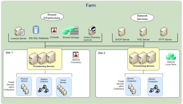
A PVS farm contains several components. Figure 15 provides a high-level view of a basic PVS infrastructure and shows how PVS components might appear within that implementation.
Figure 15. Logical Architecture of Citrix Provisioning Services
The following new features are available with Provisioning Services 1912 LTSR:
● Linux streaming
● Citrix Hypervisor proxy using PVS-Accelerator
NetApp® All Flash FAS (AFF) is a robust scale-out platform built for virtualized environments, combining low-latency performance with best-in-class data management, built-in efficiencies, integrated data protection, multiprotocol support, and nondisruptive operations. Deploy as a stand-alone system or as a high-performance tier in a NetApp ONTAP® configuration.
The NetApp AFF A400 offers full end-to-end NVMe support at the midrange. The front-end NVMe/FC connectivity makes it possible to achieve optimal performance from an all-flash array for workloads that include Virtual Desktop Environments. The AFF A-Series lineup includes the A200, A400, A700, and A800. These controllers and their specifications listed in Table 2. For more information about the A-Series AFF controllers, see:
http://www.netapp.com/us/products/storage-systems/all-flash-array/aff-a-series.aspx
https://www.netapp.com/pdf.html?item=/media/7828-ds-3582.pdf
https://hwu.netapp.com/Controller/Index?platformTypeId=13684325
Table 2. NetApp A-Series Controller Specifications
| Specifications |
AFF A250 |
AFF A400 |
AFF A700 |
| Max Raw capacity (HA) |
1101.6 TB |
14688 TB |
6609.6 TB |
| Max Storage Devices (HA) |
48 (drives) |
480 (drives) |
240 (drives) |
| Processor Speed |
2.10 Ghz |
2.20 Ghz |
2.10 Ghz |
| Total Processor Cores (Per Node) |
12 |
20 |
48 |
| Total Processor Cores (Per HA Pair) |
24 |
40 |
96 |
| Memory |
128 GB |
256 GB |
1280 GB |
| NVRAM |
16 GB |
32 GB |
64 GB |
| Ethernet Ports |
4 x RJ45 (10Gb) |
0 or 8 x SFP28 (25Gb, optional) |
- |
| Rack Units |
2 |
4 |
4 |
| Maximum number of storage virtual machines (SVMs) - SAN |
250 |
250 |
250 |
| Maximum number of flexible volumes - SAN |
400 |
400 |
400 |
This solution utilizes the NetApp AFF A400, seen in Figure 16 and Figure 17. The NetApp AFF A400 offers greater port availability, network connectivity, and expandability. When buying a storage system, most customers plan to use it for 3 to 5 years, but it’s difficult to predict how requirements may change during that time frame. The NetApp AFF A400 has 10 PCIe Gen3 slots per HA pair. Many customers have a strong preference for additional I/O capabilities, and now with the NetApp AFF A400, the increased number of PCIe Gen3 slots makes additional I/O possible.
The NetApp AFF A400 offers 25GbE or 100GbE, as well as 32Gb/FC and NVMe/FC network connectivity, which is at the leading edge of a midrange system. This model was created to keep up with changing business needs and performance and workload requirements by merging the latest technology for data acceleration and ultra-low latency in an end-to-end NVMe storage system, along with additional slots for expansion.
For more information about the AFF A-Series product family, see: http://www.netapp.com/us/products/storage-systems/all-flash-array/aff-a-series.aspx
Figure 16. NetApp AFF A400 Front View
Figure 17. NetApp AFF A400 Rear View
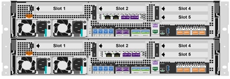 Rear Fiber Channel
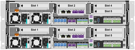 Rear Ethernet
![]()
![]() We used 4 port 32Gb FC HBA on slot 1 (1a,1b, other two ports unused) for front-end FC SAN connection, 4x25Gb Ethernet NICs on slot 0 (e0e, e0f, e0g, e0h) for NAS connectivity, 2x100Gb ethernet ports on slot 3 (e3a, e3b) used for cluster interconnect, 2x25Gb ethernet on slot 0 (e0a, e0b) used for Node HA interconnect, 2x100Gb ethernet on slot 0 (e0c, e0d) and 2x100Gb ethernet on slot 5 (e5a, e5b) are used for backend NVMe storage connectivity.
We used 4 port 32Gb FC HBA on slot 1 (1a,1b, other two ports unused) for front-end FC SAN connection, 4x25Gb Ethernet NICs on slot 0 (e0e, e0f, e0g, e0h) for NAS connectivity, 2x100Gb ethernet ports on slot 3 (e3a, e3b) used for cluster interconnect, 2x25Gb ethernet on slot 0 (e0a, e0b) used for Node HA interconnect, 2x100Gb ethernet on slot 0 (e0c, e0d) and 2x100Gb ethernet on slot 5 (e5a, e5b) are used for backend NVMe storage connectivity.
ONTAP Features for VDI
The following are the ONTAP features for VDI:
● Secure Multi-Tenancy
Tenants can be in overlapping subnet or can use identical IP subnet range.
● Multi-Protocol
Same storage system can be used for Block/File/Object storage demands.
● FlexGroup Volumes
High performance and massive capacity (~20PB and ~40 billion files) for file shares and for hosting VDI pools.
● FlexCache
Enables Single Global Namespace can be consumed around the clouds or multi-site.
● File System Analytics
Fast query to file metadata on the SMB file share.
● Ease of management with vCenter Plugins
Best practices are validated and implemented while provisioning. Supports VAAI and VASA for fast provisioning and storage capability awareness.
● SnapCenter integration with vCenter
Space efficient data protection with snapshots and FlexClones.
● Automation support
Supports RESTapi, has modules for Ansible, PowerShell, and so on.
● Storage Efficiency
Supports inline dedupe, compression, thin provisioning, etc. Guaranteed dedupe of 8:1 for VDI.
● Adaptive QoS
Adjusts QoS setting based on space consumption.
● ActiveIQ Unified Manager
Application based storage provisioning, Performance Monitoring, End-End storage visibility diagrams.
Storage efficiency has always been a primary architectural design point of ONTAP. A wide array of features allows businesses to store more data using less space. In addition to deduplication and compression, businesses can store their data more efficiently by using features such as unified storage, multi-tenancy, thin provisioning, and NetApp Snapshot® technology.
Starting with ONTAP 9, NetApp guarantees that the use of NetApp storage efficiency technologies on AFF systems reduce the total logical capacity used to store customer data by 75 percent, a data reduction ratio of 4:1. This space reduction is a combination of several different technologies, such as deduplication, compression, and compaction, which provide additional reduction to the basic features provided by ONTAP.
Compaction, which is introduced in ONTAP 9, is the latest patented storage efficiency technology released by NetApp. In the NetApp WAFL® file system, all I/O takes up 4KB of space, even if it does not actually require 4KB of data. Compaction combines multiple blocks that are not using their full 4KB of space together into one block. This one block can be more efficiently stored on the disk-to-save space. This process is illustrated in Figure 18.
Storage Efficiency Features
The storage efficiency features are as follows:
Deduplication reduces the amount of physical storage required for a volume (or all the volumes in an AFF aggregate) by discarding duplicate blocks and replacing them with references to a single shared block. Reads of deduplicated data typically incur no performance charge. Writes incur a negligible charge except on overloaded nodes.
As data is written during normal use, WAFL uses a batch process to create a catalog of block signatures. After deduplication starts, ONTAP compares the signatures in the catalog to identify duplicate blocks. If a match exists, a byte-by-byte comparison is done to verify that the candidate blocks have not changed since the catalog was created. Only if all the bytes match is the duplicate block discarded and its disk space reclaimed.
● Compression
Compression reduces the amount of physical storage required for a volume by combining data blocks in compression groups, each of which is stored as a single block. Reads of compressed data are faster than in traditional compression methods because ONTAP decompresses only the compression groups that contain the requested data, not an entire file or LUN.
You can perform inline or postprocess compression, separately or in combination:
● Inline compression compresses data in memory before it is written to disk, significantly reducing the amount of write I/O to a volume, but potentially degrading write performance. Performance-intensive operations are deferred until the next postprocess compression operation, if any.
● Postprocess compression compresses data after it is written to disk, on the same schedule as deduplication.
● Compaction
Small files or I/O padded with zeros are stored in a 4 KB block whether or not they require 4 KB of physical storage. Inline data compaction combines data chunks that would ordinarily consume multiple 4 KB blocks into a single 4 KB block on disk. Compaction takes place while data is still in memory, so it is best suited to faster controllers (Figure 18).
Figure 18. Storage Efficiency Features

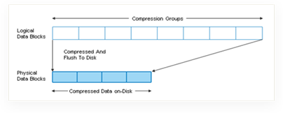
Figure 19. Storage Efficiency
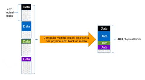
![]() Some applications such as Oracle and SQL have unique headers in each of their data blocks that prevent the blocks to be identified as duplicates. So, for such applications, enabling deduplication does not result in significant savings. So, deduplication is not recommended to be enabled for databases. However, NetApp data compression works very well with databases and we strongly recommend enabling compression for databases. Table 3 lists some guidelines where compression, deduplication and/or inline Zero block deduplication can be used. These are guidelines, not rules; environment may have different performance requirements and specific use cases.
Some applications such as Oracle and SQL have unique headers in each of their data blocks that prevent the blocks to be identified as duplicates. So, for such applications, enabling deduplication does not result in significant savings. So, deduplication is not recommended to be enabled for databases. However, NetApp data compression works very well with databases and we strongly recommend enabling compression for databases. Table 3 lists some guidelines where compression, deduplication and/or inline Zero block deduplication can be used. These are guidelines, not rules; environment may have different performance requirements and specific use cases.
Table 3. Compression and Deduplication Guidelines
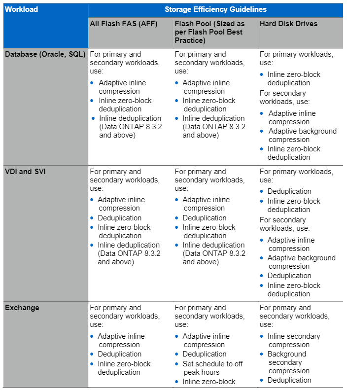
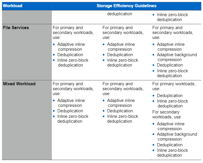
NetApp Storage Virtual Machine (SVM)
An SVM is a logical abstraction that represents the set of physical resources of the cluster. This adds extra security and peace of mind to your VDI environment, giving you another place besides vCenter to apply HA, High Availability. Data volumes and network logical interfaces (LIFs) are created and assigned to an SVM and may reside on any node in the cluster to which the SVM has been given access. An SVM may own resources on multiple nodes concurrently, and those resources can be moved non-disruptively from one node to another. For example, a flexible volume can be non-disruptively moved to a new node and aggregate, or a data LIF can be transparently reassigned to a different physical network port. The SVM abstracts the cluster hardware, and it is not tied to any specific physical hardware.
An SVM can support multiple data protocols concurrently. Volumes within the SVM can be joined together to form a single NAS namespace, which makes all of an SVM's data available through a single share or mount point to create a VMware NFS datastore for your VDI desktop folders. SVMs also support block-based protocols, and LUNs can be created and exported by using iSCSI, FC, or FCoE. Any or all of these data protocols can be configured for use within a given SVM to support your VDI needs.
Figure 20. NetApp Storage Virtual Machine
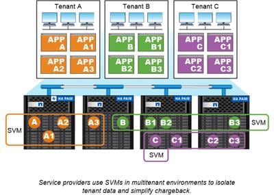
FlexClones
FlexClone technology references Snapshot metadata to create writable, point-in-time copies of a volume. Copies share data blocks with their parents, consuming no storage except what is required for metadata until changes are written to the copy. FlexClone files and FlexClone LUNs use identical technology, except that a backing Snapshot copy is not required.
Where traditional copies can take minutes or even hours to create, FlexClone software lets you copy even the largest datasets almost instantaneously. That makes it ideal for situations in which you need multiple copies of identical datasets (a virtual desktop deployment, for example) or temporary copies of a dataset (testing an application against a production dataset).
You can clone an existing FlexClone volume, clone a volume containing LUN clones, or clone mirror and vault data. You can split a FlexClone volume from its parent, in which case the copy is allocated its own storage.
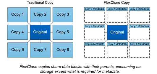
NetApp recommends implementing SAN boot for Cisco UCS servers in the FlexPod Datacenter solution. Doing so enables the ESXI host to be safely secured by the NetApp All Flash FAS storage system, providing better performance. In this design, FC SAN boot is validated.
In FC SAN boot, each Cisco UCS server boots by connecting the NetApp All Flash FAS storage to the Cisco MDS switch. The 16G FC storage ports, in this example 0g and 0h, are connected to Cisco MDS switch. The FC LIFs are created on the physical ports and each FC LIF is uniquely identified by its target WWPN. The storage system target WWPNs can be zoned with the server initiator WWPNs in the Cisco MDS switches. The FC boot LUN is exposed to the servers through the FC LIF using the MDS switch; this enables only the authorized server to have access to the boot LUN. Figure 21 shows the port and LIF layout.
Figure 21. FC - SVM ports and LIF layout
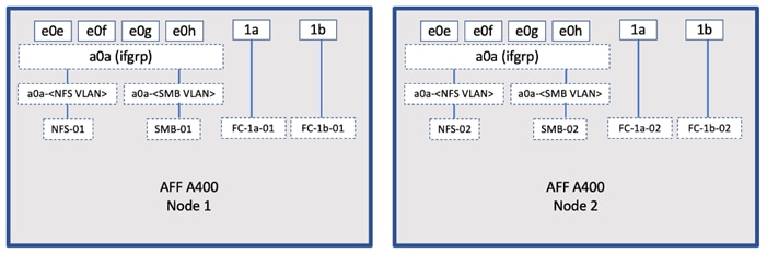
Unlike NAS network interfaces, the SAN network interfaces are not configured to fail over during a failure. Instead if a network interface becomes unavailable, the ESXI host chooses a new optimized path to an available network interface. ALUA is a standard supported by NetApp used to provide information about SCSI targets, which allows a host to identify the best path to the storage.
ONTAP 9.3 brought an innovation in scale-out NAS file systems: NetApp FlexGroup volumes, which plays a major role to give ONTAP the ability to be scaled nondisruptively out to 24 storage nodes while not degrading the performance of the VDI infrastructure.
With FlexGroup volumes, a storage administrator can easily provision a massive single namespace in a matter of seconds. FlexGroup volumes have virtually no capacity or file count constraints outside of the physical limits of hardware or the total volume limits of ONTAP. Limits are determined by the overall number of constituent member volumes that work in collaboration to dynamically balance load and space allocation evenly across all members. There is no required maintenance or management overhead with a FlexGroup volume. You simply create the FlexGroup volume and share it with your NAS clients. ONTAP does the rest.
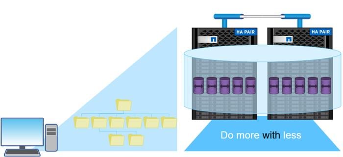
Storage QoS (Quality of Service) can help you manage risks around meeting your performance objectives. You use Storage QoS to limit the throughput to workloads and to monitor workload performance. You can reactively limit workloads to address performance problems and you can pro-actively limit workloads to prevent performance problems.
A workload represents the input/output (I/O) operations to one of the following kinds of storage objects:
● FlexVol volumes
● LUNs
You assign a storage object to a policy group to control and monitor a workload. You can monitor workloads without controlling them.
Figure 22 shows an example environment before and after using Storage QoS. On the left, workloads compete for cluster resources to transmit I/O. These workloads get "best effort" performance, which means you have less performance predictability (for example, a workload might get such good performance that it negatively impacts other workloads). On the right are the same workloads assigned to policy groups. The policy groups enforce a maximum throughput limit.
Figure 22. Before and After using Storage QoS
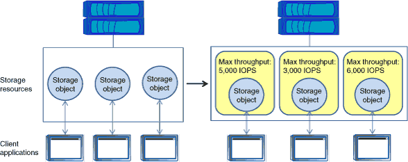
NetApp storage quality of service (QoS) works with both SAN and NAS storage, and it runs across the entire NetApp product line from entry to enterprise. Storage QoS offers significant benefits for all types of VDI environments and lets you:
● Achieve greater levels of consolidation
● Set maximum and minimum limits on multiple VDI workloads that require separate service level agreements (SLAs)
● Add additional workloads with less risk of interference
● Make sure your customers get what they pay for, but not more
Adaptive QoS
Adaptive QoS automatically scales the policy group (A policy group defines the throughput ceiling for one or more workloads) value to workload (A workload represents the I/O operations for a storage object: a volume, file, qtree or LUN, or all the volumes, files, qtrees, or LUNs in an SVM) size, for the size of the workload changes. That is a significant advantage when you are managing hundreds or thousands of workloads in a VDI deployment. With Adaptive QoS, Ceiling and Floor limit can be set using allocated or used space. The QoS also address HA and Scaling as it will assist in both efforts to produce a non-disruptive change during VDI growth by maintaining the ratio of IOPS to TBs/GBs. To assist in managing your QOS, Active IQ unified manager will provide QOS suggestions based on historical performance and usage.
Three default adaptive QoS policy groups are available, as shown in Table 4. You can apply these policy groups directly to a volume.
Table 4. Available Default Adaptive QoS Policy Groups
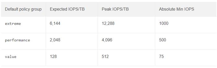
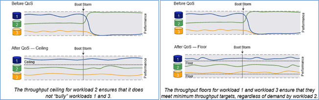
Security and Data Protection
Vscan
With Vscan you can use integrated antivirus functionality on NetApp storage systems to protect data from being compromised by viruses or other malicious code. NetApp virus scanning, called Vscan, combines best-in-class third-party antivirus software with ONTAP features that give you the flexibility you need to control which files get scanned and when.
Storage systems offload scanning operations to external servers hosting antivirus software from third-party vendors. The ONTAP Antivirus Connector, provided by NetApp and installed on the external server, handles communication between the storage system and the antivirus software.
You can use on-access scanning to check for viruses when clients open, read, rename, or close files over CIFS. File operation is suspended until the external server reports the scan status of the file. If the file has already been scanned, ONTAP allows the file operation. Otherwise, it requests a scan from the server.
You can use on-demand scanning to check files for viruses immediately or on a schedule. You might want to run scans only in off-peak hours, for example. The external server updates the scan status of the checked files, so that file-access latency for those files (assuming they have not been modified) is typically reduced when they are next accessed over CIFS. You can use on-demand scanning for any path in the SVM namespace, even for volumes that are exported only through NFS.
Typically, you enable both scanning modes on an SVM. In either mode, the antivirus software takes remedial action on infected files based on your settings in the software.
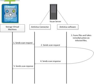
NetApp Volume Encryption (NVE) and NetApp Aggregate Encryption (NAE)
NetApp Volume Encryption is a software-based, data-at-rest encryption solution that is FIPS 140-2 compliant. NVE allows ONTAP to encrypt data for each volume for granularity. NAE, is an outgrowth of NVE; it allows ONTAP to encrypt data for each volume, and the volumes can share keys across the aggregate. NVE and NAE enable you to use storage efficiency features that would be lost with encryption at the application layer. For greater storage efficiency, you can use aggregate deduplication with NAE.
Here’s how the process works: The data leaves the disk encrypted, is sent to RAID, is decrypted by the CryptoMod, and is then sent up the rest of the stack. This process is outlined in Figure 23.
Figure 23. NVE and NAE Process
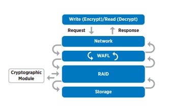
To view the latest security features for ONTAP 9, go to: Security Features in ONTAP 9 | NetApp.
ONTAP Rest API
ONTAP Rest API enables you to automate the deployment and administration of your ONTAP storage systems using one of several available options. The ONTAP REST API provides the foundation for all the various ONTAP automation technologies.
Beginning with ONTAP 9.6, ONTAP includes an expansive workflow-driven REST API that you can use to automate deployment and management of your storage. In addition, NetApp provides a Python client library, which makes it easier to write robust code, as well as support for ONTAP automation based on Ansible.
AutoSupport and Active IQ Digital Advisor
ONTAP offers artificial intelligence-driven system monitoring and reporting through a web portal and through a mobile app. The AutoSupport component of ONTAP sends telemetry that is analyzed by Active IQ Digital Advisor. Active IQ enables you to optimize your data infrastructure across your global hybrid cloud by delivering actionable predictive analytics and proactive support through a cloud-based portal and mobile app. Data-driven insights and recommendations from Active IQ are available to all NetApp customers with an active SupportEdge contract (features vary by product and support tier).
The following are some things you can do with Active IQ:
● Plan upgrades. Active IQ identifies issues in your environment that can be resolved by upgrading to a newer version of ONTAP and the Upgrade Advisor component helps you plan for a successful upgrade.
● View system wellness. Your Active IQ dashboard reports any issues with wellness and helps you correct those issues. Monitor system capacity to make sure you never run out of storage space.
● Manage performance. Active IQ shows system performance over a longer period than you can see in ONTAP System Manager. Identify configuration and system issues that are impacting your performance.
● Maximize efficiency. View storage efficiency metrics and identify ways to store more data in less space.
● View inventory and configuration. Active IQ displays complete inventory and software and hardware configuration information. View when service contracts are expiring to ensure you remain covered.
ONTAP Tools for VMware vSphere
NetApp ONTAP tools for VMware vSphere is a unified appliance that includes vSphere Storage Console (VSC),VASA Provider and SRA Provider. This vCenter web client plug-in that provides Context sensitive menu to provision traditional datastores & Virtual Volume (vVol) datastore.
ONTAP tools provides visibility into the NetApp storage environment from within the vSphere web client. VMware administrators can easily perform tasks that improve both server and storage efficiency while still using role-based access control to define the operations that administrators can perform. It includes enhanced REST APIs that provide vVols metrics for SAN storage systems using ONTAP 9.7 and later. So, NetApp OnCommand API Services is no longer required to get metrics for ONTAP systems 9.7 and later.
NetApp NFS Plug-in for VMware VAAI
The NetApp NFS Plug-in for VMware vStorage APIs - Array Integration (VAAI) is a software library that integrates the VMware Virtual Disk Libraries that are installed on the ESXi host. The VMware VAAI package enables the offloading of certain tasks from the physical hosts to the storage array. Performing those tasks at the array level can reduce the workload on the ESXi hosts.
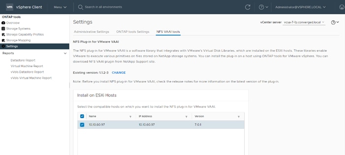
The copy offload feature and space reservation feature improve the performance of VSC operations. The NetApp NFS Plug-in for VAAI is not shipped with VSC, but you can install it by using VSC. You can download the plug-in installation package and obtain the instructions for installing the plug-in from the NetApp Support Site.
For more information about the NetApp VSC for VMware vSphere, see the NetApp Virtual Infrastructure Management product page.
NetApp SnapCenter Plug-In for VMware vSphere 4.4
NetApp SnapCenter Plug-in for VMware vSphere enables VM-consistent and crash-consistent backup and restore operations for VMs and datastores from the vCenter server. The SnapCenter plug-in is deployed as a virtual appliance and it integrates with the vCenter server web client GUI.
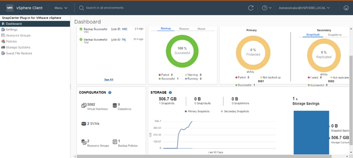
Here are some of the functionalities provided by the SnapCenter plug-in to help protect your VMs and datastores:
● Backup VMs, virtual machine disks (VMDKs), and datastores
◦ You can back up VMs, underlying VMDKs, and datastores. When you back up a datastore, you back up all the VMs in that datastore.
◦ You can create mirror copies of backups on another volume that has a SnapMirror relationship to the primary backup or perform a disk-to-disk backup replication on another volume that has a NetApp SnapVault® relationship to the primary backup volume.
◦ Backup operations are performed on all the resources defined in a resource group. If a resource group has a policy attached and a schedule configured, then backups occur automatically according to the schedule.
● Restore VMs and VMDKs from backups
◦ You can restore VMs from either a primary or secondary backup to the same ESXi server. When you restore a VM, you overwrite the existing content with the backup copy that you select.
◦ You can restore one or more VMDKs on a VM to the same datastore. You can restore existing
● VMDKs, or deleted or detached VMDKs from either a primary or a secondary backup
◦ You can attach one or more VMDKs from a primary or secondary backup to the parent VM (the same VM that the VMDK was originally associated with) or an alternate VM. You can detach the VMDK after you have restored the files you need.
◦ You can restore a deleted VM from a datastore primary or secondary backup to an ESXi host that you select.
![]() For application-consistent backup and restore operations, the NetApp SnapCenter Server software is required.
For application-consistent backup and restore operations, the NetApp SnapCenter Server software is required.
![]() For additional information, requirements, licensing, and limitations of the NetApp SnapCenter Plug-In for VMware vSphere, see the NetApp Product Documentation.
For additional information, requirements, licensing, and limitations of the NetApp SnapCenter Plug-In for VMware vSphere, see the NetApp Product Documentation.
NetApp Active IQ Unified Manager 9.8
NetApp Active IQ Unified Manager is a comprehensive monitoring and proactive management tool for NetApp ONTAP systems to help manage the availability, capacity, protection, and performance risks of your storage systems and virtual infrastructure. You can deploy Unified Manager on a Linux server, on a Windows server, or as a virtual appliance on a VMware host.
Active IQ Unified Manager enables monitoring your ONTAP storage clusters, VMware vCenter server and VMs from a single redesigned, intuitive interface that delivers intelligence from community wisdom and AI analytics. It provides comprehensive operational, performance, and proactive insights into the storage environment and the VMs running on it. When an issue occurs on the storage or virtual infrastructure, Active IQ Unified Manager can notify you about the details of the issue to help with identifying the root cause.
The VM dashboard gives you a view into the performance statistics for the VM so that you can investigate the entire I/O path from the vSphere host down through the network and finally to the storage. Some events also provide remedial actions that can be taken to rectify the issue. You can also configure custom alerts for events so that when issues occur, you are notified through email and SNMP traps.
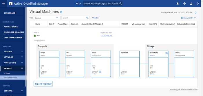
NetApp XCP File Analytics
NetApp XCP file analytics is host-based software to scan the file shares, collect and analyzes the data and provide insights into the file system. XCP file analytics works for both NetApp and non-NetApp systems and runs on Linux or Windows host. For more info, go to: http://docs.netapp.com/us-en/xcp/index.html
Architecture and Design Considerations for Desktop Virtualization
There are many reasons to consider a virtual desktop solution such as an ever growing and diverse base of user devices, complexity in management of traditional desktops, security, and even Bring Your Own Device (BYOD) to work programs. The first step in designing a virtual desktop solution is to understand the user community and the type of tasks that are required to successfully execute their role. The following user classifications are provided:
● Knowledge Workers today do not just work in their offices all day – they attend meetings, visit branch offices, work from home, and even coffee shops. These anywhere workers expect access to all of their same applications and data wherever they are.
● External Contractors are increasingly part of your everyday business. They need access to certain portions of your applications and data, yet administrators still have little control over the devices they use and the locations they work from. Consequently, IT is stuck making trade-offs on the cost of providing these workers a device vs. the security risk of allowing them access from their own devices.
● Task Workers perform a set of well-defined tasks. These workers access a small set of applications and have limited requirements from their PCs. However, since these workers are interacting with your customers, partners, and employees, they have access to your most critical data.
● Mobile Workers need access to their virtual desktop from everywhere, regardless of their ability to connect to a network. In addition, these workers expect the ability to personalize their PCs, by installing their own applications and storing their own data, such as photos and music, on these devices.
● Shared Workstation users are often found in state-of-the-art University and business computer labs, conference rooms or training centers. Shared workstation environments have the constant requirement to re-provision desktops with the latest operating systems and applications for the needs of the organization change, tops the list.
After the user classifications have been identified and the business requirements for each user classification have been defined, it becomes essential to evaluate the types of virtual desktops that are needed based on user requirements. There are essentially five potential desktops environments for each user:
● Traditional PC: A traditional PC is what typically constitutes a desktop environment: a physical device with a locally installed operating system.
● Hosted Shared Desktop: A hosted, server-based desktop is a desktop where the user interacts through a delivery protocol. With hosted, server-based desktops, a single installed instance of a server operating system, such as Microsoft Windows Server 2016, is shared by multiple users simultaneously. Each user receives a desktop "session" and works in an isolated memory space. Remoted Desktop Server Hosted Server sessions: A hosted virtual desktop is a virtual desktop running on a virtualization layer (ESX). The user does not work with and sit in front of the desktop, but instead, the user interacts through a delivery protocol.
● Published Applications: Published applications run entirely on the Citrix RDS server virtual machines and the user interacts through a delivery protocol. With published applications, a single installed instance of an application, such as Microsoft Office, is shared by multiple users simultaneously. Each user receives an application "session" and works in an isolated memory space.
● Streamed Applications: Streamed desktops and applications run entirely on the user‘s local client device and are sent from a server on demand. The user interacts with the application or desktop directly, but the resources may only available while they are connected to the network.
● Local Virtual Desktop: A local virtual desktop is a desktop running entirely on the user‘s local device and continues to operate when disconnected from the network. In this case, the user’s local device is used as a type 1 hypervisor and is synced with the data center when the device is connected to the network.
Understanding Applications and Data
When the desktop user groups and sub-groups have been identified, the next task is to catalog group application and data requirements. This can be one of the most time-consuming processes in the VDI planning exercise but is essential for the VDI project’s success. If the applications and data are not identified and co-located, performance will be negatively affected.
The process of analyzing the variety of application and data pairs for an organization will likely be complicated by the inclusion cloud applications, for example, SalesForce.com. This application and data analysis is beyond the scope of this Cisco Validated Design but should not be omitted from the planning process. There are a variety of third-party tools available to assist organizations with this crucial exercise.
Project Planning and Solution Sizing Sample Questions
Now that user groups, their applications, and their data requirements are understood, some key project and solution sizing questions may be considered.
General project questions should be addressed at the outset, including:
● Has a VDI pilot plan been created based on the business analysis of the desktop groups, applications, and data?
● Is there infrastructure and budget in place to run the pilot program?
● Are the required skill sets to execute the VDI project available? Can we hire or contract for them?
● Do we have end user experience performance metrics identified for each desktop sub-group?
● How will we measure success or failure?
● What is the future implication of success or failure?
Below is a short, non-exhaustive list of sizing questions that should be addressed for each user sub-group:
● What is the desktop OS planned? Windows 8 or Windows 10?
● 32 bit or 64 bit desktop OS?
● How many virtual desktops will be deployed in the pilot? In production? All Windows 8/10?
● How much memory per target desktop group desktop?
● Are there any rich media, Flash, or graphics-intensive workloads?
● Are there any applications installed? What application delivery methods will be used, Installed, Streamed, Layered, Hosted, or Local?
● What is the OS planned for RDS Server Roles? Windows Server 2012 or Server 2016?
● What is the hypervisor for the solution?
● What is the storage configuration in the existing environment?
● Are there sufficient IOPS available for the write-intensive VDI workload?
● Will there be storage dedicated and tuned for VDI service?
● Is there a voice component to the desktop?
● Is anti-virus a part of the image?
● What is the SQL server version for the database? SQL server 2012 or 2016?
● Is user profile management (for example, non-roaming profile based) part of the solution?
● What is the fault tolerance, failover, disaster recovery plan?
● Are there additional desktop sub-group specific questions?
VMware vSphere has been identified for the hypervisor for both HSD Sessions and HVD based desktops.
VMware vSphere: VMware vSphere comprises the management infrastructure or virtual center server software and the hypervisor software that virtualizes the hardware resources on the servers. It offers features like Distributed Resource Scheduler, vMotion, high availability, Storage vMotion, VMFS, and a multi-pathing storage layer. More information on vSphere can be obtained at the VMware website: http://www.vmware.com/products/datacentervirtualization/vsphere/overview.html.
![]() For this CVD, the hypervisor used was VMware ESXi 7.01 Update 1.
For this CVD, the hypervisor used was VMware ESXi 7.01 Update 1.
Citrix Virtual Apps & Desktops Design Fundamentals
An ever growing and diverse base of user devices, complexity in management of traditional desktops, security, and even Bring Your Own (BYO) device to work programs are prime reasons for moving to a virtual desktop solution.
Citrix Virtual Apps & Desktops 1912 LTSR integrates Hosted Shared and VDI desktop virtualization technologies into a unified architecture that enables a scalable, simple, efficient, and manageable solution for delivering Windows applications and desktops as a service.
Users can select applications from an easy-to-use “store” that is accessible from tablets, smartphones, PCs, Macs, and thin clients. Citrix Virtual Apps & Desktops delivers a native touch-optimized experience with HDX high-definition performance, even over mobile networks.
Collections of identical Virtual Machines (VMs) or physical computers are managed as a single entity called a Machine Catalog. In this CVD, VM provisioning relies on Citrix Provisioning Services to make sure that the machines in the catalog are consistent. In this CVD, machines in the Machine Catalog are configured to run either a Windows Server OS (for RDS hosted shared desktops) or a Windows Desktop OS (for hosted pooled VDI desktops).
To deliver desktops and applications to users, you create a Machine Catalog and then allocate machines from the catalog to users by creating Delivery Groups. Delivery Groups provide desktops, applications, or a combination of desktops and applications to users. Creating a Delivery Group is a flexible way of allocating machines and applications to users. In a Delivery Group, you can:
● Use machines from multiple catalogs
● Allocate a user to multiple machines
● Allocate multiple users to one machine
As part of the creation process, you specify the following Delivery Group properties:
● Users, groups, and applications allocated to Delivery Groups
● Desktop settings to match users' needs
● Desktop power management options
Figure 24 illustrates how users access desktops and applications through machine catalogs and delivery groups.
![]() The Server OS and Desktop OS Machines configured in this CVD support the hosted shared desktops and hosted virtual desktops (both non-persistent and persistent).
The Server OS and Desktop OS Machines configured in this CVD support the hosted shared desktops and hosted virtual desktops (both non-persistent and persistent).
Figure 24. Access Desktops and Applications through Machine Catalogs and Delivery Groups
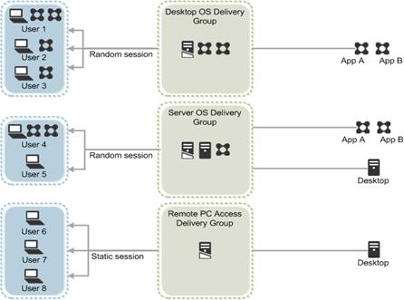
Citrix Virtual Apps & Desktops 1912 LTSR can be deployed with or without Citrix Provisioning Services (PVS). The advantage of using Citrix PVS is that it allows virtual machines to be provisioned and re-provisioned in real-time from a single shared-disk image. In this way administrators can completely eliminate the need to manage and patch individual systems and reduce the number of disk images that they manage, even for the number of machines continues to grow, simultaneously providing the efficiencies of a centralized management with the benefits of distributed processing.
The Provisioning Services solution’s infrastructure is based on software-streaming technology. After installing and configuring Provisioning Services components, a single shared disk image (vDisk) is created from a device’s hard drive by taking a snapshot of the OS and application image, and then storing that image as a vDisk file on the network. A device that is used during the vDisk creation process is the Master target device. Devices or virtual machines that use the created vDisks are called target devices.
When a target device is turned on, it is set to boot from the network and to communicate with a Provisioning Server. Unlike thin-client technology, processing takes place on the target device.
Figure 25. Citrix Provisioning Services Functionality
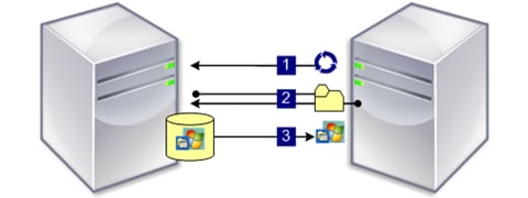
The target device downloads the boot file from a Provisioning Server (Step 2) and boots. Based on the boot configuration settings, the appropriate vDisk is mounted on the Provisioning Server (Step 3). The vDisk software is then streamed to the target device as needed, appearing as a regular hard drive to the system.
Instead of immediately pulling all the vDisk contents down to the target device (as with traditional imaging solutions), the data is brought across the network in real-time as needed. This approach allows a target device to get a completely new operating system and set of software in the time it takes to reboot. This approach dramatically decreases the amount of network bandwidth required and making it possible to support a larger number of target devices on a network without impacting performance
Citrix PVS can create desktops as Pooled or Private:
● Pooled Desktop: A pooled virtual desktop uses Citrix PVS to stream a standard desktop image to multiple desktop instances upon boot.
● Private Desktop: A private desktop is a single desktop assigned to one distinct user.
The alternative to Citrix Provisioning Services for pooled desktop deployments is Citrix Machine Creation Services (MCS), which is integrated with the Citrix Virtual Apps & Desktops Studio console.
Locate PVS Write Cache
When considering a PVS deployment, there are some design decisions that need to be made regarding the write cache for the target devices that leverage provisioning services. The write cache is a cache of all data that the target device has written. If data is written to the PVS vDisk in a caching mode, the data is not written back to the base vDisk. Instead, it is written to a write cache file in one of the following locations:
● Cache on device hard drive. Write cache exists as a file in NTFS format, located on the target-device’s hard drive. This option frees up the Provisioning Server since it does not have to process write requests and does not have the finite limitation of RAM.
● Cache on device hard drive persisted. (Experimental Phase) This is the same as “Cache on device hard drive”, except that the cache persists. At this time, this method is an experimental feature only, and is only supported for NT6.1 or later (Windows 10 and Windows 2008 R2 and later). This method also requires a different bootstrap.
● Cache in device RAM. Write cache can exist as a temporary file in the target device’s RAM. This provides the fastest method of disk access since memory access is always faster than disk access.
● Cache in device RAM with overflow on hard disk. This method uses VHDX differencing format and is only available for Windows 10 and Server 2008 R2 and later. When RAM is zero, the target device write cache is only written to the local disk. When RAM is not zero, the target device write cache is written to RAM first. When RAM is full, the least recently used block of data is written to the local differencing disk to accommodate newer data on RAM. The amount of RAM specified is the non-paged kernel memory that the target device will consume.
● Cache on a server. Write cache can exist as a temporary file on a Provisioning Server. In this configuration, all writes are handled by the Provisioning Server, which can increase disk I/O and network traffic. For additional security, the Provisioning Server can be configured to encrypt write cache files. Since the write-cache file persists on the hard drive between reboots, encrypted data provides data protection in the event a hard drive is stolen.
● Cache on server persisted. This cache option allows for the saved changes between reboots. Using this option, a rebooted target device is able to retrieve changes made from previous sessions that differ from the read only vDisk image. If a vDisk is set to this method of caching, each target device that accesses the vDisk automatically has a device-specific, writable disk file created. Any changes made to the vDisk image are written to that file, which is not automatically deleted upon shutdown.
![]() In this CVD, Provisioning Server 1912 LTSR was used to manage Pooled/Non-Persistent VDI Machines and RDS Machines with “Cache in device RAM with Overflow on Hard Disk” for each virtual machine. This design enables good scalability to many thousands of desktops. Provisioning Server 1912 LTSR was used for Active Directory machine account creation and management as well as for streaming the shared disk to the hypervisor hosts.
In this CVD, Provisioning Server 1912 LTSR was used to manage Pooled/Non-Persistent VDI Machines and RDS Machines with “Cache in device RAM with Overflow on Hard Disk” for each virtual machine. This design enables good scalability to many thousands of desktops. Provisioning Server 1912 LTSR was used for Active Directory machine account creation and management as well as for streaming the shared disk to the hypervisor hosts.
Example Citrix Virtual Apps & Desktops Deployments
Two examples of typical Citrix Virtual Apps & Desktops deployments are the following:
● A distributed components configuration
● A multiple site configuration
Since RDS and Citrix Virtual Apps & Desktops 1912 LTSR are based on a unified architecture, combined they can deliver a combination of Hosted Shared Desktops (HSDs, using a Server OS machine) and Hosted Virtual Desktops (HVDs, using a Desktop OS).
Distributed Components Configuration
You can distribute the components of your deployment among a greater number of servers or provide greater scalability and failover by increasing the number of controllers in your site. You can install management consoles on separate computers to manage the deployment remotely. A distributed deployment is necessary for an infrastructure based on remote access through NetScaler Gateway (formerly called Access Gateway).
Figure 26 shows an example of a distributed components configuration. A simplified version of this configuration is often deployed for an initial proof-of-concept (POC) deployment. The CVD described in this document deploys Citrix Virtual Apps & Desktops in a configuration that resembles this distributed components configuration shown. Two Cisco UCS B200M5 blade servers host the required infrastructure services (AD, DNS, DHCP, License Server, SQL, Citrix Virtual Apps & Desktops management, and StoreFront servers).
Figure 26. Example of a Distributed Components Configuration
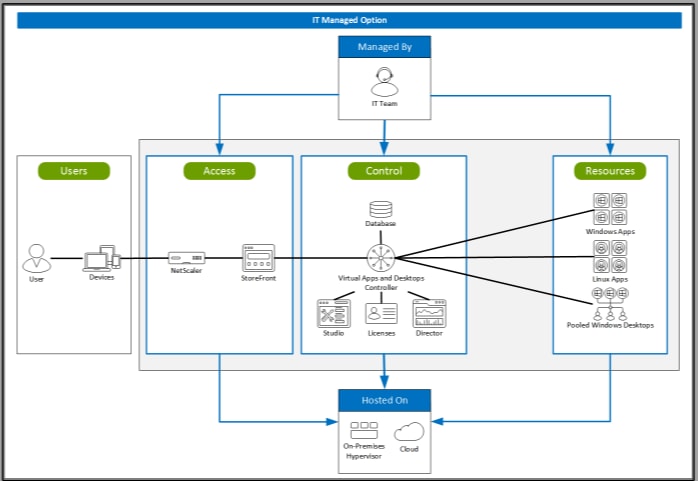
If you have multiple regional sites, you can use Citrix NetScaler to direct user connections to the most appropriate site and StoreFront to deliver desktops and applications to users.
Figure 27 depicts multiple sites with a site created in two data centers. Having two sites globally, rather than just one, minimizes the amount of unnecessary WAN traffic.
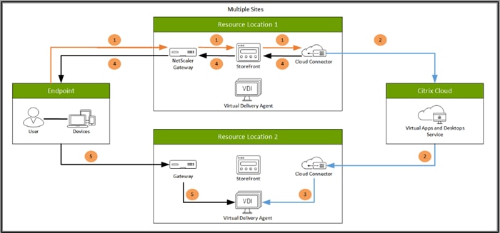
You can use StoreFront to aggregate resources from multiple sites to provide users with a single point of access with NetScaler. A separate Studio console is required to manage each site; sites cannot be managed as a single entity. You can use Director to support users across sites.
Citrix NetScaler accelerates application performance, load balances servers, increases security, and optimizes the user experience. In this example, two NetScalers are used to provide a high availability configuration. The NetScalers are configured for Global Server Load Balancing and positioned in the DMZ to provide a multi-site, fault-tolerant solution.
Easily deliver the Citrix portfolio of products as a service. Citrix Cloud services simplify the delivery and management of Citrix technologies extending existing on-premises software deployments and creating hybrid workspace services.
● Fast: Deploy apps and desktops, or complete secure digital workspaces in hours, not weeks.
● Adaptable: Choose to deploy on any cloud or virtual infrastructure — or a hybrid of both.
● Secure: Keep all proprietary information for your apps, desktops, and data under your control.
● Simple: Implement a fully-integrated Citrix portfolio via a single-management plane to simplify administration
Designing a Citrix Virtual Apps & Desktops Environment for a Mixed Workload
With Citrix Virtual Apps & Desktops 1912 LTSR, the method you choose to provide applications or desktops to users depends on the types of applications and desktops you are hosting and available system resources, as well for the types of users and user experience you want to provide.
| Server OS machines |
You want: Inexpensive server-based delivery to minimize the cost of delivering applications to a large number of users, while providing a secure, high-definition user experience. Your users: Perform well-defined tasks and do not require personalization or offline access to applications. Users may include task workers such as call center operators and retail workers, or users that share workstations. Application types: Any application. |
| Desktop OS machines |
You want: A client-based application delivery solution that is secure, provides centralized management, and supports a large number of users per host server (or hypervisor), while providing users with applications that display seamlessly in high-definition. Your users: Are internal, external contractors, third-party collaborators, and other provisional team members. Users do not require off-line access to hosted applications. Application types: Applications that might not work well with other applications or might interact with the operating system, such as .NET framework. These types of applications are ideal for hosting on virtual machines. Applications running on older operating systems such as Windows XP or Windows Vista, and older architectures, such as 32-bit or 16-bit. By isolating each application on its own virtual machine, if one machine fails, it does not impact other users. |
| Remote PC Access |
You want: Employees with secure remote access to a physical computer without using a VPN. For example, the user may be accessing their physical desktop PC from home or through a public WIFI hotspot. Depending upon the location, you may want to restrict the ability to print or copy and paste outside of the desktop. This method enables BYO device support without migrating desktop images into the datacenter. Your users: Employees or contractors that have the option to work from home but need access to specific software or data on their corporate desktops to perform their jobs remotely. Host: The same as Desktop OS machines. Application types: Applications that are delivered from an office computer and display seamlessly in high definition on the remote user's device. |
For the Cisco Validated Design described in this document, a mix of Windows Server 2019 based Hosted Shared Destops sessions (RDS), and Windows 10 Hosted Virtual desktops (Statically assigned Persistent and Random Pooled) were configured and tested.
Deployment Hardware and Software
The architecture deployed is highly modular. While each customer’s environment might vary in its exact configuration, once the reference architecture contained in this document is built, it can easily be scaled as requirements and demands change. This includes scaling both up (adding additional resources within a Cisco UCS Domain) and out (adding additional Cisco UCS Domains and NetApp AFF Storage platform).
The Citrix solution includes Cisco networking, Cisco UCS, and NetApp AFF storage, which efficiently fits into a single data center rack, including the access layer network switches.
This validated design document details the deployment of the multiple configurations extending to 6000 users for a mixed Citrix Virtual Apps & Desktops workload featuring the following software:
● Citrix RDS 1912 LTSR Hosted Shared Virtual Desktops (HSD) with PVS write cache on NFS storage
● Citrix Virtual Apps & Desktops 1912 LTSR Non-Persistent Hosted Virtual Desktops (HVD) with PVS write cache on NFS storage
● Citrix Virtual Apps & Desktops 1912 LTSR Persistent Hosted Virtual Desktops (VDI) provisioned with MCS and stored on NFS storage
● Citrix Provisioning Server 1912 LTSR
● FSlogix for Profile Management
● Citrix StoreFront 1912 LTSR
● VMware vSphere ESXi 7.01 Update 1 Hypervisor
● Microsoft Windows Server 2019 and Windows 10 (build 2004) 64-bit virtual machine Operating Systems
● Microsoft SQL Server 2017
Figure 28. Virtual Desktop and Application Workload Architecture

The workload contains the following hardware as shown in Figure 28:
● Two Cisco Nexus 93180YC-FX Layer 2 Access Switches.
● Four Cisco UCS 5108 Blade Server Chassis with two built-in UCS-IOM-2408XP IO Modules.
● Two Cisco UCS B200 M5 Blade servers with Intel Xeon Scalable 4114R 2.20-GHz 10-core processors, 19GB 2666MHz RAM, and one Cisco VIC1440 mezzanine card for the hosted infrastructure, providing N+1 server fault tolerance.
● Thirty Cisco UCS B200 M5 Blade Servers with Intel Xeon Gold 6230 2.30-GHz 20-core processors, 768GB 2933MHz RAM, and one Cisco VIC1440 mezzanine card for the desktop workload, providing N+1 server fault tolerance at the workload cluster level.
● NetApp AFF A400 Storage System with dual redundant controllers, 2x disk shelves, and 48 x 1.75 TB solid-state NVMe drives providing storage and NVME/FC/NFS/CIFS connectivity.
![]() (LoginVSI Test infrastructure is not a part of the solution) Sixteen Cisco UCS B200M4 Blade servers with Intel E5-2680 v4 processors, 256GB RAM, and VIC1240 mezzanine cards plus a NetApp FAS2240 for the Login VSI launcher and logging infrastructure.
(LoginVSI Test infrastructure is not a part of the solution) Sixteen Cisco UCS B200M4 Blade servers with Intel E5-2680 v4 processors, 256GB RAM, and VIC1240 mezzanine cards plus a NetApp FAS2240 for the Login VSI launcher and logging infrastructure.
The NetApp AFF400 configuration is detailed later in this document.
The logical architecture of the validated solution which is designed to support up to 6000 users within a single 42u rack containing 32 blades in 4 chassis, with physical redundancy for the blade servers for each workload type is outlined in Figure 29.
Figure 29. Logical Architecture Overview
This section includes the software versions of the primary products installed in the environment.
Table 5. Software Revisions
| Vendor |
Product |
Version |
| Cisco |
Cisco UCS Component Firmware |
4.1(2b) bundle release |
| Cisco |
Cisco UCS Manager |
4.1(2b) bundle release |
| Cisco |
Cisco UCS B200 M5 Blades |
4.1(2b) bundle release |
| Cisco |
Cisco VIC 1440 |
4.1(2b) |
| Cisco |
Cisco UCS B200 M5 Blades |
4.1(2b) bundle release |
| Citrix |
RDS VDA |
1912 LTSR |
| Citrix |
Citrix Virtual Apps & Desktops VDA |
1912 LTSR |
| Citrix |
Citrix Virtual Apps & Desktops Controller |
1912 LTSR |
| Citrix |
Provisioning Services |
1912 LTSR |
| Citrix |
StoreFront Services |
1912 LTSR |
| VMware |
vCenter Server Appliance |
7.01 |
| VMware |
vSphere ESXi 7.01 |
7.01.16850804 |
| NetApp |
Clustered Data ONTAP |
9.7P10 |
| NetApp |
ONTAP tools for VMware vSphere |
9.8 |
| NetApp |
ActiveIQ Unified Manager |
9.8 |
| NetApp |
SnapCenter Plug-in for VMware vSphere |
4.4 |
| NetApp |
XCP File Analytics |
1.6.3 |
The Citrix Virtual Apps & Desktops solution described in this document provides details for configuring a fully redundant, highly-available configuration. Configuration guidelines are provided that refer to which redundant component is being configured with each step, whether that be A or B. For example, Nexus A and Nexus B identify the pair of Cisco Nexus switches that are configured. The Cisco UCS Fabric Interconnects are configured similarly.
![]() This document is intended to allow you to configure the Citrix Virtual Apps & Desktops 1912 LTSR customer environment as stand-alone solution.
This document is intended to allow you to configure the Citrix Virtual Apps & Desktops 1912 LTSR customer environment as stand-alone solution.
The VLAN configuration recommended for the environment includes a total of seven VLANs as listed in Table 6.
| VLAN Name |
VLAN ID |
VLAN Purpose |
VLAN Name |
| Default |
1 |
Native VLAN |
Default |
| In-Band-Mgmt |
60 |
VLAN for in-band management interfaces |
In-Band-Mgmt |
| Infra-Mgmt |
61 |
VLAN for Virtual Infrastructure |
Infra-Mgmt |
| CIFS |
62 |
VLAN for CIFS traffic |
CIFS |
| NFS |
63 |
VLAN for Infrastructure NFS traffic |
NFS |
| vMotion |
66 |
VLAN for VMware vMotion |
vMotion |
We utilized Two VMware Clusters in one vCenter data center to support the solution and testing environment:
● VDI Cluster FlexPod Data Center with Cisco UCS
◦ Infrastructure: Infra VMs (vCenter, Active Directory, DNS, DHCP, SQL Server, Citrix Virtual Apps & Desktops Controllers, Provisioning Servers, and NetApp VSC, ActiveIQ Unified Manager, VSMs, and so on)
◦ VDI Workload VMs (Windows Server 2019 streamed with PVS, Windows 10 Streamed with PVS and persistent desktops with Machine Creation Services)
● VSI Launchers and Launcher Cluster
◦ LVS-Launcher-CLSTR: Login VSI Cluster (The Login VSI launcher infrastructure was connected using the same set of switches and vCenter instance but was hosted on separate storage and servers)
Figure 30. vCenter Data Center and Clusters Deployed
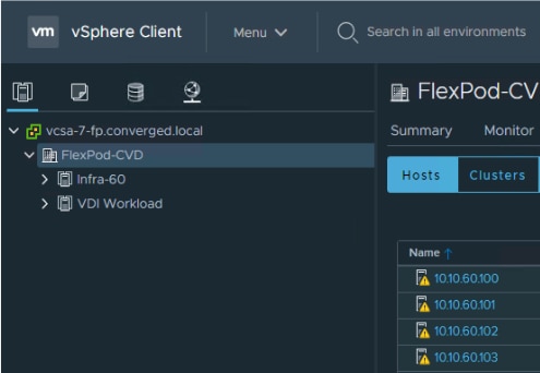
This section details the configuration and tuning that was performed on the individual components to produce a complete, validated solution.
The architecture is divided into three distinct layers:
● Cisco UCS Compute Platform
● Network Access layer and LAN
● Storage Access to the NetApp AFF400
Figure 31 details the physical connectivity configuration of the Citrix Virtual Apps & Desktops 1912 LTSR environment.
Figure 31. Cabling Diagram of the FlexPod Data Center with Cisco UCS
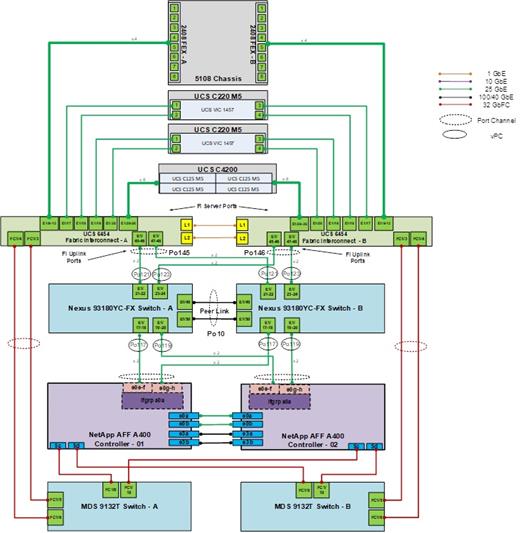
Table 7 through Table 13 list the details of all the connections in use.
Table 7. Cisco Nexus 93108-A Cabling Information
| Local Device |
Local Port |
Connection |
Remote Device |
Remote Port |
| Cisco Nexus 93108 A |
Eth1/15 |
25GbE |
NetApp Controller 2 |
e0e |
| Eth1/14 |
25GbE |
NetApp Controller 2 |
e1a |
|
| Eth1/15 |
25GbE |
NetApp Controller 1 |
e0e |
|
| Eth1/16 |
25GbE |
NetApp Controller 1 |
e4a |
|
| Eth1/17 |
25GbE |
NetApp Controller 1 |
e0h |
|
| Eth1/18 |
25GbE |
NetApp Controller 1 |
e0g |
|
| Eth1/19 |
25GbE |
NetApp Controller 2 |
e0e |
|
| Eth1/20 |
25GbE |
NetApp Controller 2 |
e0h |
|
| Eth1/21 |
25GbE |
Cisco UCS fabric interconnect A |
Eth2/1 |
|
| Eth1/22 |
25GbE |
Cisco UCS fabric interconnect A |
Eth2/2 |
|
| Eth1/23 |
25GbE |
Cisco UCS fabric interconnect B |
Eth2/3 |
|
| Eth1/24 |
25GbE |
Cisco UCS fabric interconnect B |
Eth2/4 |
|
| Eth1/49 |
40GbE |
Cisco Nexus 93108 B |
Eth1/49 |
|
| Eth1/50 |
40GbE |
Cisco Nexus 93108 B |
Eth1/50 |
|
|
|
MGMT0 |
GbE |
GbE management switch |
Any |
![]() For devices requiring GbE connectivity, use the GbE Copper SFP+s (GLC-T=).
For devices requiring GbE connectivity, use the GbE Copper SFP+s (GLC-T=).
Table 8. Cisco Nexus 93108-B Cabling Information
| Local Device |
Local Port |
Connection |
Remote Device |
Remote Port |
| Cisco Nexus 93108 B |
Eth1/14 |
25GbE |
NetApp Controller 2 |
e0g |
| Eth1/15 |
25GbE |
NetApp Controller 2 |
e1b |
|
| Eth1/16 |
25GbE |
NetApp Controller 1 |
e0g |
|
| Eth1/17 |
25GbE |
NetApp Controller 1 |
e0e |
|
| Eth1/18 |
25GbE |
NetApp Controller 1 |
e0f |
|
| Eth1/19 |
25GbE |
NetApp Controller 2 |
e0f |
|
| Eth1/20 |
25GbE |
NetApp Controller 2 |
e0g |
|
| Eth1/21 |
25GbE |
NetApp Controller 1 |
e1b |
|
| Eth1/22 |
25GbE |
Cisco UCS fabric interconnect A |
Eth2/1 |
|
| Eth1/23 |
25GbE |
Cisco UCS fabric interconnect A |
Eth2/2 |
|
| Eth1/24 |
25GbE |
Cisco UCS fabric interconnect B |
Eth2/3 |
|
| Eth1/14 |
25GbE |
Cisco UCS fabric interconnect B |
Eth2/4 |
|
| Eth1/49 |
40GbE |
Cisco Nexus 93108 B |
Eth1/49 |
|
| Eth1/50 |
40GbE |
Cisco Nexus 93108 B |
Eth1/50 |
|
|
|
MGMT0 |
GbE |
GbE management switch |
Any |
Table 9. NetApp Controller-1 Cabling Information
| Local Device |
Local Port |
Connection |
Remote Device |
Remote Port |
| NetApp AFF400 Node 1 |
e0M |
1GbE |
1GbE management switch |
Any |
| e0s |
GbE |
GbE management switch |
Any |
|
| e0a |
25GbE |
NetApp Controller 2 |
e0a |
|
| e0b |
25GbE |
NetApp Controller 2 |
e0b |
|
| e0c |
100GbE |
NS224-1 |
e0a |
|
| e0d |
100GbE |
NS224-2 |
e0b |
|
| e0e |
25GbE |
Cisco Nexus 93108 B |
Eth1/17 |
|
| e0f |
25GbE |
Cisco Nexus 93108 B |
Eth1/18 |
|
| e0g |
25GbE |
Cisco Nexus 93108 A |
Eth1/18 |
|
| e0h |
25GbE |
Cisco Nexus 93108 A |
Eth1/17 |
|
| e3a |
100GbE |
NetApp Controller 2 |
e3a |
|
| e3b |
100GbE |
NetApp Controller 2 |
e3b |
|
| e5a |
100GbE |
NS224-2 |
e0a |
|
| e5b |
100GbE |
NS224-1 |
e0b |
![]() When the term e0M is used, the physical Ethernet port to which the table is referring is the port indicated by a wrench icon on the rear of the chassis.
When the term e0M is used, the physical Ethernet port to which the table is referring is the port indicated by a wrench icon on the rear of the chassis.
Table 10. NetApp Controller 2 Cabling Information
| Local Device |
Local Port |
Connection |
Remote Device |
Remote Port |
| NetApp AFF400 Node 2 |
e0M |
100E |
100MbE management switch |
Any |
| e0s |
GbE |
GbE management switch |
Any |
|
| e0a |
25GbE |
NetApp Controller 2 |
e0a |
|
| e0b |
25GbE |
NetApp Controller 2 |
e0b |
|
| e0c |
100GbE |
NS224-1 |
e0a |
|
| e0d |
100GbE |
NS224-2 |
e0b |
|
| e0e |
25GbE |
Cisco Nexus 93108 A |
Eth1/19 |
|
| e0f |
25GbE |
Cisco Nexus 93108 B |
Eth1/19 |
|
| e0g |
25GbE |
Cisco Nexus 93108 B |
Eth1/20 |
|
| e0h |
25GbE |
Cisco Nexus 93108 A |
Eth1/20 |
|
| e3a |
100GbE |
NetApp Controller 2 |
e3a |
|
| e3b |
100GbE |
NetApp Controller 2 |
e3b |
|
| e5a |
100GbE |
NS224-2 |
e0a |
|
| e5b |
100GbE |
NS224-1 |
e0b |
Table 11. Cisco UCS Fabric Interconnect A Cabling Information
| Local Device |
Local Port |
Connection |
Remote Device |
Remote Port |
| Cisco UCS Fabric Interconnect A |
Eth2/1 |
25GbE |
Cisco Nexus 93108 A |
Eth1/17 |
| Eth2/2 |
25GbE |
Cisco Nexus 93108 A |
Eth1/18 |
|
| Eth2/3 |
25GbE |
Cisco Nexus 93108 B |
Eth1/19 |
|
| Eth2/4 |
25GbE |
Cisco Nexus 93108 B |
Eth1/20 |
|
| Eth1/1 |
25GbE |
Cisco UCS Chassis1 FEX A |
IOM 1/1 |
|
| Eth1/2 |
25GbE |
Cisco UCS Chassis1 FEX A |
IOM 1/2 |
|
| Eth1/3 |
25GbE |
Cisco UCS Chassis1 FEX A |
IOM 1/3 |
|
| Eth1/4 |
25GbE |
Cisco UCS Chassis1 FEX A |
IOM 1/4 |
|
| Eth1/5 |
25GbE |
Cisco UCS Chassis2 FEX A |
IOM 1/1 |
|
| Eth1/6 |
25GbE |
Cisco UCS Chassis2 FEX A |
IOM 1/2 |
|
| Eth1/7 |
25GbE |
Cisco UCS Chassis2 FEX A |
IOM 1/3 |
|
| Eth1/8 |
25GbE |
Cisco UCS Chassis2 FEX A |
IOM 1/4 |
|
| Eth1/9 |
25GbE |
Cisco UCS Chassis3 FEX A |
IOM 1/1 |
|
| Eth1/10 |
25GbE |
Cisco UCS Chassis3 FEX A |
IOM 1/2 |
|
| Eth1/11 |
25GbE |
Cisco UCS Chassis3 FEX A |
IOM 1/3 |
|
| Eth1/12 |
25GbE |
Cisco UCS Chassis3 FEX A |
IOM 1/4 |
|
| Eth1/13 |
25GbE |
Cisco UCS Chassis4 FEX A |
IOM 1/1 |
|
| Eth1/14 |
25GbE |
Cisco UCS Chassis4 FEX A |
IOM 1/2 |
|
| Eth1/15 |
25GbE |
Cisco UCS Chassis4 FEX A |
IOM 1/3 |
|
| Eth1/16 |
25GbE |
Cisco UCS Chassis4 FEX A |
IOM 1/4 |
|
| MGMT0 |
GbE |
GbE management switch |
Any |
|
| L1 |
GbE |
Cisco UCS fabric interconnect B |
L1 |
|
|
|
L2 |
GbE |
Cisco UCS fabric interconnect B |
L2 |
Table 12. Cisco UCS Fabric Interconnect B Cabling Information
| Local Device |
Local Port |
Connection |
Remote Device |
Remote Port |
| Cisco UCS Fabric Interconnect B
|
Eth2/1 |
25GbE |
Cisco Nexus 93108 A |
Eth1/17 |
| Eth2/2 |
25GbE |
Cisco Nexus 93108 A |
Eth1/18 |
|
| Eth2/3 |
25GbE |
Cisco Nexus 93108 B |
Eth1/19 |
|
| Eth2/4 |
25GbE |
Cisco Nexus 93108 B |
Eth1/20 |
|
| Eth1/1 |
25GbE |
Cisco UCS Chassis1 FEX B |
IOM 2/1 |
|
| Eth1/2 |
25GbE |
Cisco UCS Chassis1 FEX B |
IOM 2/2 |
|
| Eth1/3 |
25GbE |
Cisco UCS Chassis1 FEX B |
IOM 2/3 |
|
| Eth1/4 |
25GbE |
Cisco UCS Chassis1 FEX B |
IOM 2/4 |
|
| Eth1/5 |
25GbE |
Cisco UCS Chassis2 FEX B |
IOM 2/1 |
|
| Eth1/6 |
25GbE |
Cisco UCS Chassis2 FEX B |
IOM 2/2 |
|
| Eth1/7 |
25GbE |
Cisco UCS Chassis2 FEX B |
IOM 2/3 |
|
| Eth1/8 |
25GbE |
Cisco UCS Chassis2 FEX B |
IOM 2/4 |
|
| Eth1/9 |
25GbE |
Cisco UCS Chassis3 FEX B |
IOM 2/1 |
|
| Eth1/10 |
25GbE |
Cisco UCS Chassis3 FEX B |
IOM 2/2 |
|
| Eth1/11 |
25GbE |
Cisco UCS Chassis3 FEX B |
IOM 2/3 |
|
| Eth1/12 |
25GbE |
Cisco UCS Chassis3 FEX B |
IOM 2/4 |
|
| Eth1/13 |
25GbE |
Cisco UCS Chassis4 FEX B |
IOM 2/1 |
|
| Eth1/14 |
25GbE |
Cisco UCS Chassis4 FEX B |
IOM 2/2 |
|
| Eth1/15 |
25GbE |
Cisco UCS Chassis4 FEX B |
IOM 2/3 |
|
| Eth1/16 |
25GbE |
Cisco UCS Chassis4 FEX B |
IOM 2/4 |
|
| MGMT0 |
GbE |
GbE management switch |
Any |
|
| L1 |
GbE |
Cisco UCS fabric interconnect B |
L1 |
|
|
|
L2 |
GbE |
Cisco UCS fabric interconnect B |
L2 |
![]() Follow these steps precisely because failure to do so could result in an improper configuration.
Follow these steps precisely because failure to do so could result in an improper configuration.
Follow the physical connectivity guidelines for FlexPod as explained in section FlexPod Cabling.
The following procedures describe how to configure the Cisco Nexus switches for use in a base FlexPod environment. This procedure assumes the use of Cisco Nexus 9000 9.3(4), the Cisco suggested Nexus switch release at the time of this validation.
If using the Cisco Nexus 93180YC-FX switches for both LAN and SAN switching, please refer to section FlexPod with Cisco Nexus 93180YC-FX SAN Switching Configuration – Part 1 in the Appendix.
The following procedure includes the setup of NTP distribution on both the mgmt0 port and the in-band management VLAN. The interface-vlan feature and ntp commands are used to set this up. This procedure also assumes that the default VRF is used to route the in-band management VLAN.
![]() In this validation, port speed and duplex are hard set at both ends of every 100GE connection.
In this validation, port speed and duplex are hard set at both ends of every 100GE connection.
Cisco Nexus A
To set up the initial configuration for the Cisco Nexus A switch on <nexus-A-hostname>, follow these steps:
1. Configure the switch.
2. On initial boot and connection to the serial or console port of the switch, the NX-OS setup should automatically start and attempt to enter Power on Auto Provisioning.
Abort Power On Auto Provisioning [yes - continue with normal setup, skip - bypass password and basic configuration, no - continue with Power On Auto Provisioning] (yes/skip/no)[no]: yes
Disabling POAP.......Disabling POAP
poap: Rolling back, please wait... (This may take 5-15 minutes)
---- System Admin Account Setup ----
Do you want to enforce secure password standard (yes/no) [y]: Enter
Enter the password for "admin": <password>
Confirm the password for "admin": <password>
Would you like to enter the basic configuration dialog (yes/no): yes
Create another login account (yes/no) [n]: Enter
Configure read-only SNMP community string (yes/no) [n]: Enter
Configure read-write SNMP community string (yes/no) [n]: Enter
Enter the switch name: <nexus-A-hostname>
Continue with Out-of-band (mgmt0) management configuration? (yes/no) [y]: Enter
Mgmt0 IPv4 address: <nexus-A-mgmt0-ip>
Mgmt0 IPv4 netmask: <nexus-A-mgmt0-netmask>
Configure the default gateway? (yes/no) [y]: Enter
IPv4 address of the default gateway: <nexus-A-mgmt0-gw>
Configure advanced IP options? (yes/no) [n]: Enter
Enable the telnet service? (yes/no) [n]: Enter
Enable the ssh service? (yes/no) [y]: Enter
Type of ssh key you would like to generate (dsa/rsa) [rsa]: Enter
Number of rsa key bits <1024-2048> [1024]: Enter
Configure the ntp server? (yes/no) [n]: Enter
Configure default interface layer (L3/L2) [L2]: Enter
Configure default switchport interface state (shut/noshut) [noshut]: shut
Enter basic FC configurations (yes/no) [n]: n
Configure CoPP system profile (strict/moderate/lenient/dense) [strict]: Enter
Would you like to edit the configuration? (yes/no) [n]: Enter
3. Review the configuration summary before enabling the configuration.
Use this configuration and save it? (yes/no) [y]: Enter
Cisco Nexus B
To set up the initial configuration for the Cisco Nexus B switch on <nexus-B-hostname>, follow these steps:
1. Configure the switch.
2. On initial boot and connection to the serial or console port of the switch, the NX-OS setup should automatically start and attempt to enter Power on Auto Provisioning.
Abort Power On Auto Provisioning [yes - continue with normal setup, skip - bypass password and basic configuration, no - continue with Power On Auto Provisioning] (yes/skip/no)[no]: yes
Disabling POAP.......Disabling POAP
poap: Rolling back, please wait... (This may take 5-15 minutes)
---- System Admin Account Setup ----
Do you want to enforce secure password standard (yes/no) [y]: Enter
Enter the password for "admin": <password>
Confirm the password for "admin": <password>
Would you like to enter the basic configuration dialog (yes/no): yes
Create another login account (yes/no) [n]: Enter
Configure read-only SNMP community string (yes/no) [n]: Enter
Configure read-write SNMP community string (yes/no) [n]: Enter
Enter the switch name: <nexus-B-hostname>
Continue with Out-of-band (mgmt0) management configuration? (yes/no) [y]: Enter
Mgmt0 IPv4 address: <nexus-B-mgmt0-ip>
Mgmt0 IPv4 netmask: <nexus-B-mgmt0-netmask>
Configure the default gateway? (yes/no) [y]: Enter
IPv4 address of the default gateway: <nexus-B-mgmt0-gw>
Configure advanced IP options? (yes/no) [n]: Enter
Enable the telnet service? (yes/no) [n]: Enter
Enable the ssh service? (yes/no) [y]: Enter
Type of ssh key you would like to generate (dsa/rsa) [rsa]: Enter
Number of rsa key bits <1024-2048> [1024]: Enter
Configure the ntp server? (yes/no) [n]: Enter
Configure default interface layer (L3/L2) [L2]: Enter
Configure default switchport interface state (shut/noshut) [noshut]: shut
Enter basic FC configurations (yes/no) [n]: Enter
Configure CoPP system profile (strict/moderate/lenient/dense) [strict]: Enter
Would you like to edit the configuration? (yes/no) [n]: Enter
3. Review the configuration summary before enabling the configuration.
Use this configuration and save it? (yes/no) [y]: Enter
FlexPod Cisco Nexus Switch Configuration
Cisco Nexus A and Cisco Nexus B
SAN switching requires both the SAN_ENTERPRISE_PKG and FC_PORT_ACTIVATION_PKG licenses. Please ensure these licenses are installed on each Nexus 93180YC-FX switch. To enable the appropriate features on the Cisco Nexus switches, follow these steps:
1. Log in as admin.
2. Since basic FC configurations were entered in the setup script, feature-set fcoe has been automatically installed and enabled. Run the following commands:
config t
feature udld
feature interface-vlan
feature lacp
feature vpc
feature lldp
Cisco Nexus A and Cisco Nexus B
To set global configurations, follow this step on both switches:
1. Run the following commands to set global configurations:
spanning-tree port type network default
spanning-tree port type edge bpduguard default
spanning-tree port type edge bpdufilter default
port-channel load-balance src-dst l4port
ntp server <global-ntp-server-ip> use-vrf management
ntp master 3
clock timezone <timezone> <hour-offset> <minute-offset>
clock summer-time <timezone> <start-week> <start-day> <start-month> <start-time> <end-week> <end-day> <end-month> <end-time> <offset-minutes>
ip route 0.0.0.0/0 <ib-mgmt-vlan-gateway>
copy run start
It is important to configure the local time so that logging time alignment and any backup schedules are correct. For more information on configuring the timezone and daylight savings time or summer time, please see Cisco Nexus 9000 Series NX-OS Fundamentals Configuration Guide, Release 9.3(x). Sample clock commands for the United States Eastern timezone are:
clock timezone EST -5 0
clock summer-time EDT 2 Sunday March 02:00 1 Sunday November 02:00 60
Cisco Nexus A and Cisco Nexus B
To create the necessary virtual local area networks (VLANs), follow this step on both switches:
1. From the global configuration mode, run the following commands:
vlan <ib-mgmt-vlan-id>
name IB-MGMT-VLAN
vlan <native-vlan-id>
name Native-VLAN
vlan <vmotion-vlan-id>
name vMotion-VLAN
vlan <vm-traffic-vlan-id>
name VM-Traffic-VLAN
vlan <infra-nfs-vlan-id>
name Infra-NFS-VLAN
exit
Add NTP Distribution Interface
Cisco Nexus A
1. From the global configuration mode, run the following commands:
interface Vlan<ib-mgmt-vlan-id>
ip address <switch-a-ntp-ip>/<ib-mgmt-vlan-netmask-length>
no shutdown
exit
ntp peer <switch-b-ntp-ip> use-vrf default
Cisco Nexus B
1. From the global configuration mode, run the following commands:
interface Vlan<ib-mgmt-vlan-id>
ip address <switch-b-ntp-ip>/<ib-mgmt-vlan-netmask-length>
no shutdown
exit
ntp peer <switch-a-ntp-ip> use-vrf default
This version of the FlexPod solution uses port profiles for virtual port channel (vPC) connections to NetApp Storage, Cisco UCS, and the vPC peer link. To add port profiles, follow these steps:
Cisco Nexus A and Cisco Nexus B
1. From the global configuration mode, run the following commands:
port-profile type port-channel FP-ONTAP-Storage
switchport mode trunk
switchport trunk native vlan <native-vlan-id>
switchport trunk allowed vlan <ib-mgmt-vlan-id>, <infra-nfs-vlan-id>
spanning-tree port type edge trunk
mtu 9216
state enabled
port-profile type port-channel FP-UCS
switchport mode trunk
switchport trunk native vlan <native-vlan-id>
switchport trunk allowed vlan <ib-mgmt-vlan-id>, <infra-nfs-vlan-id>, <vmotion-vlan-id>, <vm-traffic-vlan-id>
spanning-tree port type edge trunk
mtu 9216
state enabled
port-profile type port-channel vPC-Peer-Link
switchport mode trunk
switchport trunk native vlan <native-vlan-id>
switchport trunk allowed vlan <ib-mgmt-vlan-id>, <infra-nfs-vlan-id>, <vmotion-vlan-id>, <vm-traffic-vlan-id>
spanning-tree port type network
speed 100000
duplex full
state enabled
Add Individual Port Descriptions for Troubleshooting and Enable UDLD for Cisco UCS Interfaces
Cisco Nexus A
To add individual port descriptions for troubleshooting activity and verification for switch A, follow these steps:
1. In this step and in the following sections, configure the AFF nodename <st-node> and Cisco UCS 6454 fabric interconnect clustername <ucs-clustername> interfaces as appropriate to your deployment.
2. From the global configuration mode, run the following commands:
interface Eth1/21
description <ucs-clustername>-a:1/45
udld enable
interface Eth1/22
description <ucs-clustername>-a:1/46
udld enable
interface Eth1/23
description <ucs-clustername>-b:1/45
udld enable
interface Eth1/24
description <ucs-clustername>-b:1/46
udld enable
3. For fibre optic connections to Cisco UCS systems (AOC or SFP-based), entering udld enable will result in a message stating that this command is not applicable to fiber ports. This message is expected. If you have fibre optic connections, do not enter the udld enable command.
interface Eth1/17
description <st-clustername>-01:e0e
interface Eth1/18
description <st-clustername>-01:e0f
interface Eth1/19
description <st-clustername>-02:e0e
interface Eth1/20
description <st-clustername>-02:e0f
interface Eth1/49
description <nexus-b-hostname>:1/49
interface Eth1/50
description <nexus-b-hostname>:1/50
exit
Cisco Nexus B
To add individual port descriptions for troubleshooting activity and verification for switch B and to enable aggressive UDLD on copper interfaces connected to Cisco UCS systems, follow this step:
1. From the global configuration mode, run the following commands:
interface Eth1/21
description <ucs-clustername>-a:1/47
udld enable
interface Eth1/22
description <ucs-clustername>-a:1/48
udld enable
interface Eth1/23
description <ucs-clustername>-b:1/47
udld enable
interface Eth1/24
description <ucs-clustername>-b:1/48
udld enable
2. For fibre optic connections to Cisco UCS systems (AOC or SFP-based), entering udld enable will result in a message stating that this command is not applicable to fiber ports. This message is expected.
interface Eth1/17
description <st-clustername>-01:e0g
interface Eth1/18
description <st-clustername>-01:e0h
interface Eth1/19
description <st-clustername>-02:e0g
interface Eth1/20
description <st-clustername>-02:e0h
interface Eth1/49
description <nexus-a-hostname>:1/49
interface Eth1/50
description <nexus-a-hostname>:1/50
exit
Cisco Nexus A and Cisco Nexus B
To create the necessary port channels between devices, follow this step on both switches:
1. From the global configuration mode, run the following commands:
interface Po10
description vPC peer-link
interface Eth1/49-50
channel-group 10 mode active
no shutdown
interface Po117
description <st-clustername>-01
interface Eth1/17-18
channel-group 117 mode active
no shutdown
interface Po119
description <st-clustername>-02
interface Eth1/19-20
channel-group 119 mode active
no shutdown
interface Po121
description <ucs-clustername>-a
interface Eth1/21-22
channel-group 121 mode active
no shutdown
interface Po123
description <ucs-clustername>-b
interface Eth1/23-24
channel-group 123 mode active
no shutdown
exit
copy run start
Configure Port Channel Parameters
Cisco Nexus A and Cisco Nexus B
To configure port channel parameters, follow this step on both switches:
1. From the global configuration mode, run the following commands:
interface Po10
inherit port-profile vPC-Peer-Link
interface Po117
inherit port-profile FP-ONTAP-Storage
interface Po119
inherit port-profile FP-ONTAP-Storage
interface Po121
inherit port-profile FP-UCS
interface Po123
inherit port-profile FP-UCS
exit
copy run start
Configure Virtual Port Channels
Cisco Nexus A
To configure virtual port channels (vPCs) for switch A, follow this step:
1. From the global configuration mode, run the following commands:
vpc domain <nexus-vpc-domain-id>
role priority 10
peer-keepalive destination <nexus-B-mgmt0-ip> source <nexus-A-mgmt0-ip>
peer-switch
peer-gateway
auto-recovery
delay restore 150
ip arp synchronize
interface Po10
vpc peer-link
interface Po117
vpc 117
interface Po119
vpc 119
interface Po121
vpc 121
interface Po123
vpc 123
exit
copy run start
Cisco Nexus B
To configure vPCs for switch B, follow this step:
1. From the global configuration mode, run the following commands:
vpc domain <nexus-vpc-domain-id>
role priority 20
peer-keepalive destination <nexus-A-mgmt0-ip> source <nexus-B-mgmt0-ip>
peer-switch
peer-gateway
auto-recovery
delay restore 150
ip arp synchronize
interface Po10
vpc peer-link
interface Po117
vpc 117
interface Po119
vpc 119
interface Po121
vpc 121
interface Po123
vpc 123
exit
copy run start
Uplink into Existing Network Infrastructure
Depending on the available network infrastructure, several methods and features can be used to uplink the FlexPod environment. If an existing Cisco Nexus environment is present, we recommend using vPCs to uplink the Cisco Nexus switches included in the FlexPod environment into the infrastructure. The previously described procedures can be used to create an uplink vPC to the existing environment. Make sure to run copy run start to save the configuration on each switch after the configuration is completed.
The following commands can be used to check for correct switch configuration:
![]() Some of these commands need to run after completing the configuration of the FlexPod components to see all results.
Some of these commands need to run after completing the configuration of the FlexPod components to see all results.
show run
show vpc
show port-channel summary
show ntp peer-status
show cdp neighbors
show lldp neighbors
show run int
show int
show udld neighbors
show int status
See the following section (NetApp Hardware Universe) for planning the physical location of the storage systems:
● Site Preparation
● System Connectivity Requirements
● Circuit Breaker, Power Outlet Balancing, System Cabinet Power Cord Plugs, and Console Pinout Requirements
● AFF Series Systems
To confirm that the hardware and software components that you would like to use are supported with the version of ONTAP that you plan to install, follow these steps at the NetApp Support site.
Access the HWU application to view the System Configuration guides. Click the Platforms menu to view the compatibility between different version of the ONTAP software and the NetApp storage appliances with your desired specifications.
Alternatively, to compare components by storage appliance, click Compare Storage Systems.
Follow the physical installation procedures for the controllers found here: http://docs.netapp.com/platstor/index.jsp?topic=%2Fcom.netapp.nav.a400%2Fhome.html on the NetApp Support site.
NetApp storage systems support a wide variety of disk shelves and disk drives. The complete list of disk shelves that are supported by the AFF A400 and AFF A800 is available at the NetApp Support site.
When using SAS disk shelves with NetApp storage controllers, refer to the SAS cabling rules section in the AFF and FAS System Documentation Center for proper cabling guidelines.
When using NVMe drive shelves with NetApp storage controllers, refer to the NS224 Drive Shelves documentation for installation and servicing guidelines.
Complete Configuration Worksheet
Before running the setup script, complete the Cluster setup worksheet in the ONTAP 9 Documentation Center. You must have access to the NetApp Support site to open the cluster setup worksheet.
![]() We reused some content from FlexPod Platform guide. There will be minor differences (for example node name, IP Address, and so on) between the images and our validation environment.
We reused some content from FlexPod Platform guide. There will be minor differences (for example node name, IP Address, and so on) between the images and our validation environment.
Before running the setup script, review the configuration worksheets in the Software setup section of the ONTAP 9 Documentation Center to learn about configuring ONTAP. Table 13 lists the information needed to configure two ONTAP nodes. Customize the cluster-detail values with the information applicable to your deployment.
Table 13. ONTAP Software Installation Prerequisites
| Cluster Detail |
Cluster Detail Value |
| Cluster node 01 IP address |
<node01-mgmt-ip> |
| Cluster node 01 netmask |
<node01-mgmt-mask> |
| Cluster node 01 gateway |
<node01-mgmt-gateway> |
| Cluster node 02 IP address |
<node02-mgmt-ip> |
| Cluster node 02 netmask |
<node02-mgmt-mask> |
| Cluster node 02 gateway |
<node02-mgmt-gateway> |
| ONTAP 9.7 URL |
<url-boot-software> |
Configure Node 01
To configure node 01, follow these steps:
1. Connect to the storage system console port. You should see a Loader-A prompt. However, if the storage system is in a reboot loop, press Ctrl-C to exit the autoboot loop when the following message displays:
Starting AUTOBOOT press Ctrl-C to abort…
2. Allow the system to boot up.
autoboot
3. Press Ctrl-C when prompted.
4. If ONTAP 9.7 is not the version of software being booted, continue with the following steps to install new software. If ONTAP 9.7 is the version being booted, choose option 8 and y to reboot the node.
5. To install new software, choose option 7 from the menu.
6. Enter y to continue the installation.
7. Choose e0M for the network port you want to use for the download.
8. Enter n to skip the reboot.
9. Choose option 7 from the menu: Install new software first
10. Enter y to continue the installation
11. Enter the IP address, netmask, and default gateway for e0M.
Enter the IP address for port e0M: <node01-mgmt-ip>
Enter the netmask for port e0M: <node01-mgmt-mask>
Enter the IP address of the default gateway: <node01-mgmt-gateway>
12. Enter the URL where the software can be found.
![]() The web server must be pingable from node 01.
The web server must be pingable from node 01.
<url-boot-software>
13. Press Enter for the user name, indicating no user name.
14. Enter y to set the newly installed software for the default to be used for subsequent reboots.
15. Enter yes to reboot the node.
![]() When installing new software, the system might perform firmware upgrades to the BIOS and adapter cards, causing reboots and possible stops at the Loader-A prompt. If these actions occur, the system might deviate from this procedure.
When installing new software, the system might perform firmware upgrades to the BIOS and adapter cards, causing reboots and possible stops at the Loader-A prompt. If these actions occur, the system might deviate from this procedure.
![]() During the ONTAP installation a prompt to reboot the node requests a Y/N response. The prompt requires the entire Yes or No response to reboot the node and continue the installation.
During the ONTAP installation a prompt to reboot the node requests a Y/N response. The prompt requires the entire Yes or No response to reboot the node and continue the installation.
16. Press Ctrl-C when the following message displays:
Press Ctrl-C for Boot Menu
17. Choose option 4 for Clean Configuration and Initialize All Disks.
18. Enter y to zero disks, reset config, and install a new file system.
19. Enter yes to erase all the data on the disks.
![]() The initialization and creation of the root aggregate can take 90 minutes or more to complete, depending on the number and type of disks attached. When initialization is complete, the storage system reboots. Note that SSDs take considerably less time to initialize. You can continue with the configuration of node 02 while the disks for node 01 are zeroing.
The initialization and creation of the root aggregate can take 90 minutes or more to complete, depending on the number and type of disks attached. When initialization is complete, the storage system reboots. Note that SSDs take considerably less time to initialize. You can continue with the configuration of node 02 while the disks for node 01 are zeroing.
Configure Node 02
To configure node 02, follow these steps:
1. Connect to the storage system console port. You should see a Loader-B prompt. However, if the storage system is in a reboot loop, press Ctrl-C to exit the autoboot loop when the following message displays:
Starting AUTOBOOT press Ctrl-C to abort…
2. Allow the system to boot up.
autoboot
3. Press Ctrl-C when prompted.
![]() If ONTAP 9.7 is not the version of software being booted, continue with the following steps to install new software. If ONTAP 9.7 is the version being booted, choose option 8 and y to reboot the node, then continue with step 16.
If ONTAP 9.7 is not the version of software being booted, continue with the following steps to install new software. If ONTAP 9.7 is the version being booted, choose option 8 and y to reboot the node, then continue with step 16.
4. To install new software, choose option 7.
5. Enter y to continue the installation.
6. Choose e0M for the network port you want to use for the download.
7. Enter n to skip the reboot.
8. Choose option 7: Install new software first
9. Enter y to continue the installation
10. Enter the IP address, netmask, and default gateway for e0M.
Enter the IP address for port e0M: <node02-mgmt-ip>
Enter the netmask for port e0M: <node02-mgmt-mask>
Enter the IP address of the default gateway: <node02-mgmt-gateway>
11. Enter the URL where the software can be found.
![]() The web server must be pingable from node 02.
The web server must be pingable from node 02.
<url-boot-software>
12. Press Enter for the user name, indicating no user name.
13. Enter y to set the newly installed software for the default to be used for subsequent reboots.
14. Enter yes to reboot the node.
![]() When installing new software, the system might perform firmware upgrades to the BIOS and adapter cards, causing reboots and possible stops at the Loader-A prompt. If these actions occur, the system might deviate from this procedure.
When installing new software, the system might perform firmware upgrades to the BIOS and adapter cards, causing reboots and possible stops at the Loader-A prompt. If these actions occur, the system might deviate from this procedure.
![]() During the ONTAP installation a prompt to reboot the node requests a Y/N response. The prompt requires the entire Yes or No response to reboot the node and continue the installation.
During the ONTAP installation a prompt to reboot the node requests a Y/N response. The prompt requires the entire Yes or No response to reboot the node and continue the installation.
15. Press Ctrl-C when you see this message:
Press Ctrl-C for Boot Menu
16. Choose option 4 for Clean Configuration and Initialize All Disks.
17. Enter y to zero disks, reset config, and install a new file system.
18. Enter yes to erase all the data on the disks.
![]() The initialization and creation of the root aggregate can take 90 minutes or more to complete, depending on the number and type of disks attached. When initialization is complete, the storage system reboots. Note that SSDs take considerably less time to initialize.
The initialization and creation of the root aggregate can take 90 minutes or more to complete, depending on the number and type of disks attached. When initialization is complete, the storage system reboots. Note that SSDs take considerably less time to initialize.
From a console port program attached to the storage controller A (node 01) console port, run the node setup script. This script appears when ONTAP 9.7 boots on the node for the first time. To set up the node, follow these steps:
1. Follow the prompts to set up node 01.
Welcome to node setup.
You can enter the following commands at any time:
"help" or "?" - if you want to have a question clarified,
"back" - if you want to change previously answered questions, and
"exit" or "quit" - if you want to quit the setup wizard.
Any changes you made before quitting will be saved.
You can return to cluster setup at any time by typing “cluster setup”.
To accept a default or omit a question, do not enter a value.
This system will send event messages and weekly reports to NetApp Technical Support.
To disable this feature, enter "autosupport modify -support disable" within 24 hours.
Enabling AutoSupport can significantly speed problem determination and resolution should a problem occur on your system.
For further information on AutoSupport, see:
http://support.netapp.com/autosupport/
Type yes to confirm and continue {yes}: yes
Enter the node management interface port [e0M]: Enter
Enter the node management interface IP address: <node01-mgmt-ip>
Enter the node management interface netmask: <node01-mgmt-mask>
Enter the node management interface default gateway: <node01-mgmt-gateway>
A node management interface on port e0M with IP address <node01-mgmt-ip> has been created
Use your web browser to complete cluster setup by accesing https://<node01-mgmt-ip>
Otherwise press Enter to complete cluster setup using the command line interface:
2. To complete cluster setup, open a web browser and navigate to https://<node01-mgmt-ip>.
Table 14. Cluster Create in ONTAP Prerequisites
| Cluster Detail |
Cluster Detail Value |
| Cluster name |
<clustername> |
| Cluster Admin SVM |
<cluster-adm-svm> |
| Infrastructure Data SVM |
<infra-data-svm> |
| ONTAP base license |
<cluster-base-license-key> |
| Cluster management IP address |
<clustermgmt-ip> |
| Cluster management netmask |
<clustermgmt-mask> |
| Cluster management gateway |
<clustermgmt-gateway> |
| Cluster node 01 IP address |
<node01-mgmt-ip> |
| Cluster node 01 netmask |
<node01-mgmt-mask> |
| Cluster node 01 gateway |
<node01-mgmt-gateway> |
| Cluster node 02 IP address |
<node02-mgmt-ip> |
| Cluster node 02 netmask |
<node02-mgmt-mask> |
| Cluster node 02 gateway |
<node02-mgmt-gateway> |
| Node 01 service processor IP address |
<node01-sp-ip> |
| Node 01 service processor network mask |
<node01-sp-mask> |
| Node 01 service processor gateway |
<node01-sp-gateway> |
| Node 02 service processor IP address |
<node02-sp-ip> |
| Node 02 service processor network mask |
<node02-sp-mask> |
| Node 02 service processor gateway |
<node02-sp-gateway> |
| Node 01 node name |
<st-node01> |
| Node 02 node name |
<st-node02> |
| DNS domain name |
<dns-domain-name> |
| DNS server IP address |
<dns-ip> |
| NTP server A IP address |
<switch-a-ntp-ip> |
| NTP server B IP address |
<switch-b-ntp-ip> |
| SNMPv3 User |
<snmp-v3-usr> |
| SNMPv3 Authentication Protocol |
<snmp-v3-auth-proto> |
| SNMPv3 Privacy Protocol |
<snmpv3-priv-proto> |
![]() Cluster setup can also be performed using the CLI. This document describes the cluster setup using the NetApp ONTAP System Manager guided setup.
Cluster setup can also be performed using the CLI. This document describes the cluster setup using the NetApp ONTAP System Manager guided setup.
3. Complete the required information on the Initialize Storage System screen:
In the Cluster screen, follow these steps:
1. Enter the cluster name and administrator password.
2. Complete the Networking information for the cluster and each node.
3. Choose the box Use time services (NTP) and enter the IP addresses of the time servers in a comma separated list.
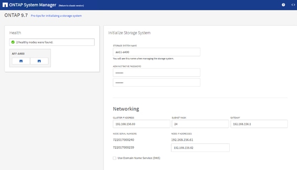
![]() The nodes should be discovered automatically; if they are not, Refresh the browser page. By default, the cluster interfaces are created on all the new factory shipping storage controllers.
The nodes should be discovered automatically; if they are not, Refresh the browser page. By default, the cluster interfaces are created on all the new factory shipping storage controllers.
![]() If all the nodes are not discovered, then configure the cluster using the command line.
If all the nodes are not discovered, then configure the cluster using the command line.
![]() The node management interface can be on the same subnet for the cluster management interface, or it can be on a different subnet. In this document, we assume that it is on the same subnet.
The node management interface can be on the same subnet for the cluster management interface, or it can be on a different subnet. In this document, we assume that it is on the same subnet.
4. Click Submit.
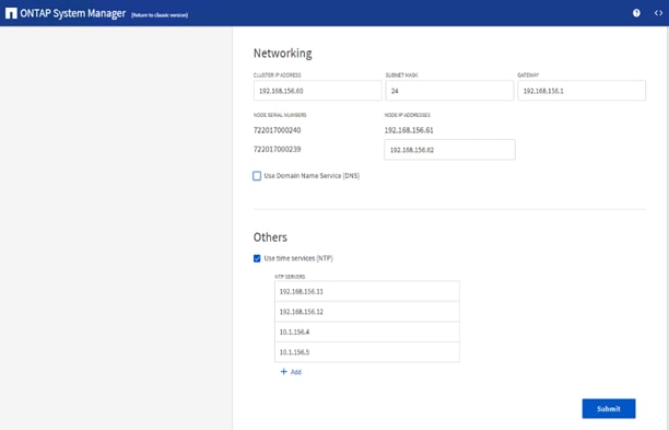
5. A few minutes will pass while the cluster is configured. When prompted, login to ONTAP System Manager to continue the cluster configuration.
6. From the Dashboard click the Cluster menu on the left and choose Overview.
7. Click the Details ellipsis button in the Overview pane and choose Edit.
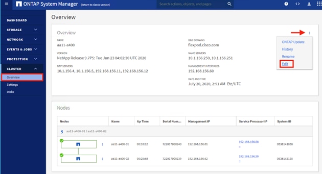
8. Add additional cluster configuration details and click Save to make the changes persistent:
a. Cluster location
b. DNS domain name
c. DNS server IP addresses
![]() DNS server IP addresses can be added individually or with a comma separated list on a single line.
DNS server IP addresses can be added individually or with a comma separated list on a single line.
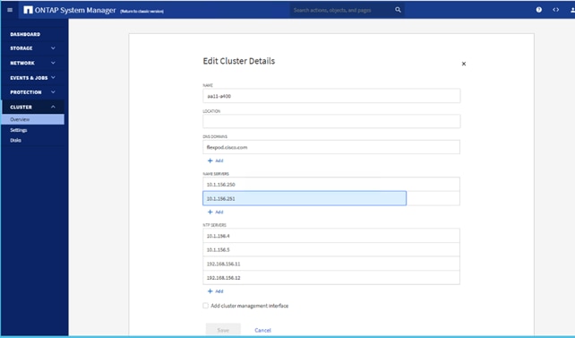
9. Click Save to make the changes persistent.
10. To configure AutoSupport, add licenses and create storage aggregates via the ONTAP CLI, skip this section and configure the options in section Configure and Test AutoSuport.
11. Click the ellipsis in the top right of the AutoSupport tile and choose More options.
12. Choose the Settings menu under the Cluster menu.
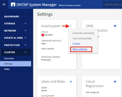
13. If AutoSupport was not configured during the initial setup, click the ellipsis in the AutoSupport tile and choose More options.
14. To enable AutoSupport click the slider button.
15. Click Edit to change the transport protocol, add a proxy server address and a mail host as needed.
16. Click Save to enable the changes.
17. In the Email tile to the right, click Edit and enter the desired email information:
a. Email send from address
b. Email recipient addresses
c. Recipient Category
18. Click Save when complete.
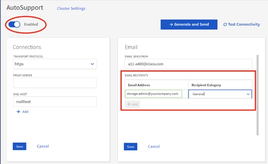
19. Choose Cluster Settings at the top left of the page to return to the cluster settings page.
20. Locate the Licenses tile on the right and click the detail arrow.
21. Add the desired licenses to the cluster by clicking Add and entering the license keys in a comma separated list.
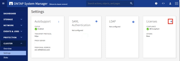
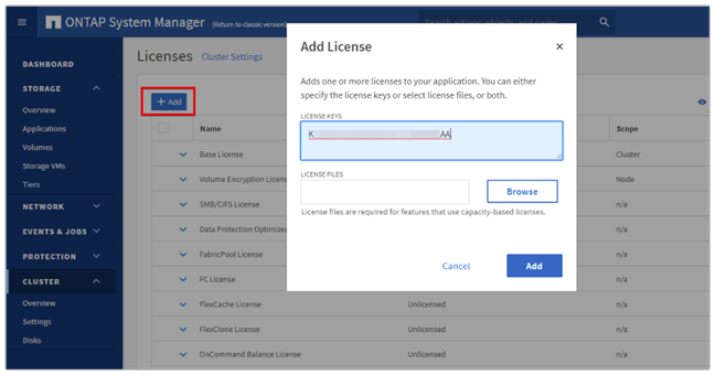
22. Configure storage aggregates by selecting the Storage menu on the left and choosing Tiers.
23. Click Add Local Tier and allow ONTAP System Manager to recommend a storage aggregate configuration.
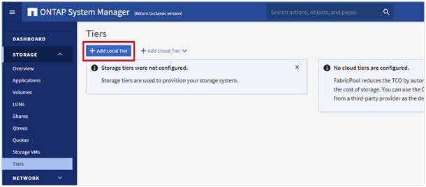
24. ONTAP will use best practices to recommend an aggregate layout. Click the Recommended details link to view the aggregate information.
25. Optionally, enable NetApp Aggregate Encryption (NAE) by selecting the Configure Onboard Key Manager for encryption check box.
26. Enter and confirm the passphrase and save it in a secure location for future use.
27. Click Save to make the configuration persistent.

![]() Careful consideration should be taken before enabling aggregate encryption. Aggregate encryption may not be supported for all deployments. Please review the NetApp Encryption Power Guide and the Security Hardening Guide for NetApp ONTAP 9 (TR-4569) to help determine if aggregate encryption is right for your environment.
Careful consideration should be taken before enabling aggregate encryption. Aggregate encryption may not be supported for all deployments. Please review the NetApp Encryption Power Guide and the Security Hardening Guide for NetApp ONTAP 9 (TR-4569) to help determine if aggregate encryption is right for your environment.
To log into the cluster, follow these steps:
1. Open an SSH connection to either the cluster IP or the host name.
2. Log into the admin user with the password you provided earlier.
To confirm that storage failover is enabled, run the following commands for a failover pair:
1. Verify the status of the storage failover.
storage failover show
2. Both <st-node01> and <st-node02> must be capable of performing a takeover. Continue with step 69 if the nodes are capable of performing a takeover.
3. Enable failover on one of the two nodes if it was not completed during the installation.
storage failover modify -node <st-node01> -enabled true
![]() Enabling failover on one node enables it for both nodes.
Enabling failover on one node enables it for both nodes.
4. Verify the HA status for a two-node cluster.
![]() This step is not applicable for clusters with more than two nodes.
This step is not applicable for clusters with more than two nodes.
cluster ha show
5. Continue with step 7 if high availability is configured.
6. Only enable HA mode for two-node clusters. Do not run this command for clusters with more than two nodes because it causes problems with failover.
cluster ha modify -configured true
Do you want to continue? {y|n}: y
7. Verify that hardware assist is correctly configured.
storage failover hwassist show
Set Auto-Revert on Cluster Management
To set the auto-revert parameter on the cluster management interface, follow these steps:
1. A storage virtual machine (SVM) is referred to as a Vserver or vserver in the GUI and CLI.
2. Run the following command:
net interface modify -vserver <clustername> -lif cluster_mgmt_lif_1 -auto-revert true
To zero all spare disks in the cluster, run the following command:
disk zerospares
Advanced Data Partitioning creates a root partition and two data partitions on each SSD drive in an AFF configuration. Disk autoassign should have assigned one data partition to each node in an HA pair. If a different disk assignment is required, disk autoassignment must be disabled on both nodes in the HA pair by running the disk option modify command. Spare partitions can then be moved from one node to another by running the disk removeowner and disk assign commands.
Set Up Service Processor Network Interface
To assign a static IPv4 address to the Service Processor on each node, run the following commands:
system service-processor network modify –node <st-node01> -address-family IPv4 –enable true –dhcp none –ip-address <node01-sp-ip> -netmask <node01-sp-mask> -gateway <node01-sp-gateway>
system service-processor network modify –node <st-node02> -address-family IPv4 –enable true –dhcp none –ip-address <node02-sp-ip> -netmask <node02-sp-mask> -gateway <node02-sp-gateway>
The Service Processor IP addresses should be in the same subnet for the node management IP addresses.
Create Auto-provisioned Aggregates
It is a best practice to allow ONTAP to create auto provisioned aggregates. The auto provisioning tool will create a storage layout including the appropriate number of spare disks according to ONTAP best practices. To create new storage aggregates with the auto provisioning tool, run the following commands, or skip to the manual aggregate creation steps below.
aa11-a400::*> storage aggregate auto-provision -verbose
Per node summary of new aggregates to create, discovered spares, and also
remaining spare disks and partitions after aggregate creation:
New Total New -Discovered Spare- -Remaining Spare-
Node Aggrs Usable Size Disks Partitions Disks Partitions
------------------ ----- ------------ ------ ----------- ------ ----------
aa11-a400-01 1 16.29TB 0 24 0 1
aa11-a400-02 1 16.29TB 0 24 0 1
------------------ ----- ------------ ------ ----------- ------ ----------
Total: 2 32.57TB 0 48 0 2
New data aggregates to create with counts of
disks and partitions to be used:
-Devices To Use-
Node New Data Aggregate Usable Size Disks Partitions
------------------ ---------------------------- ------------ ----- ----------
aa11-a400-01 aa11_a400_01_NVME_SSD_1 16.29TB 0 23
aa11-a400-02 aa11_a400_02_NVME_SSD_1 16.29TB 0 23
RAID group layout showing how spare disks and partitions will be used
in new data aggregates to be created:
RAID Group In New Disk Usable Disk Or ---Count---
Data Aggregate To Be Created Type Size Partition Data Parity
-------------------------------------- ------ ---------- --------- ---- ------
/aa11_a400_01_NVME_SSD_1/plex0/rg0 NVMe-SSD 882.4GB partition 21 2
/aa11_a400_02_NVME_SSD_1/plex0/rg0 NVMe-SSD 882.4GB partition 21 2
Details about spare disks and partitions remaining after aggregate creation:
Disk Device Disk Or Remaining
Node Type Usable Size Partition Spares
------------------ ------ ------------ --------- ---------
aa11-a400-01 NVMe-SSD 882.4GB partition 1
aa11-a400-02 NVMe-SSD 882.4GB partition 1
Do you want to create recommended aggregates? {y|n}: y
Info: Aggregate auto provision has started. Use the "storage aggregate
show-auto-provision-progress" command to track the progress.
Auto provisioning is not supported for use with MetroCluster or third-party array LUNs. Refer to the Aggregate creation workflow within the Disk and Aggregate Management chapter of the ONTAP 9 Cluster Administration guide for more information.
When using aggregate auto provisioning you cannot specify the aggregate names, however they can be changed via the ONTAP CLI or System Manager after the aggregates have been created.
Create Manual Provisioned Aggregates (Optional)
An aggregate containing the root volume is created during the ONTAP setup process. To manually create additional aggregates, determine the aggregate name, the node on which to create it, and the number of disks it should contain.
To create new aggregates, run the following commands:
storage aggregate create -aggregate aggr1_node01 -node <st-node01> -diskcount <num-disks>
storage aggregate create -aggregate aggr1_node02 -node <st-node02> -diskcount <num-disks>
storage aggregate auto-provision -verbose
You should have the minimum number of hot spare disks for hot spare disk partitions recommended for your aggregate.
For all-flash aggregates, you should have a minimum of one hot spare disk or disk partition. For non-flash homogenous aggregates, you should have a minimum of two hot spare disks or disk partitions. For Flash Pool aggregates, you should have a minimum of two hot spare disks or disk partitions for each disk type.
In an AFF configuration with a small number of SSDs, you might want to create an aggregate with all, but one remaining disk (spare) assigned to the controller.
The aggregate cannot be created until disk zeroing completes. Run the storage aggregate show command to display the aggregate creation status. Do not proceed until both aggr1_node1 and aggr1_node2 are online.
Remove Ports from Default Broadcast Domain
By default, all network ports are included in the default broadcast domain. Network ports used for data services (for example, e0e, e0f, and so on) should be removed from the default broadcast domain, leaving just the management network port (e0M). To perform this task, run the following commands:
network port broadcast-domain remove-ports -broadcast-domain Default -port <st-node01>:e0e,<st-node02>:e0e,<st-node01>:e0f,<st-node02>:e0f,<st-node01>:e0g,<st-node02>:e0g,<st-node01>:e0h,<st-node02>:e0h
network port broadcast-domain show
Disable Flow Control on 25/100GbE Ports
To disable flow control on 25 and 100GbE ports, follow these steps:
1. Run the following command to configure the ports on node 01:
network port modify -node <st-node01> -port e3a,e3b -flowcontrol-admin none network port modify -node <st-node01> -port e0e,e0f,e0g,e0h -flowcontrol-admin none
2. Run the following command to configure the ports on node 02:
network port modify -node <st-node02> -port e3a,e3b -flowcontrol-admin none
network port modify -node <st-node02> -port e0e,e0f,e0g,e0h -flowcontrol-admin none
aa11-a400::*> net port show -node * -port e0e,e0f,e0g,e0h -fields speed-admin,duplex-admin,flowcontrol-admin
(network port show)
node port duplex-admin speed-admin flowcontrol-admin
------------ ---- ------------ ----------- -----------------
aa11-a400-01 e0e full 25000 none
aa11-a400-01 e0f full 25000 none
aa11-a400-01 e0g full 25000 none
aa11-a400-01 e0h full 25000 none
aa11-a400-02 e0e full 25000 none
aa11-a400-02 e0f full 25000 none
aa11-a400-02 e0g full 25000 none
aa11-a400-02 e0h full 25000 none
8 entries were displayed.
aa11-a400::*> net port show -node * -port e4a,e4b -fields speed-admin,duplex-admin,flowcontrol-admin
(network port show)
node port duplex-admin speed-admin flowcontrol-admin
------------ ---- ------------ ----------- -----------------
aa11-a400-01 e4a full 100000 none
aa11-a400-01 e4b full 100000 none
aa11-a400-02 e4a full 100000 none
aa11-a400-02 e4b full 100000 none
4 entries were displayed.
Disable Auto-Negotiate on Fibre Channel Ports
In accordance with the best practices for FC host ports, to disable auto-negotiate on each FCP adapter in each controller node, follow these steps:
1. Disable each FC adapter in the controllers with the fcp adapter modify command:
fcp adapter modify -node <st-node01> -adapter 1a –status-admin down
fcp adapter modify -node <st-node01> -adapter 1b –status-admin down
fcp adapter modify -node <st-node02> -adapter 1a –status-admin down
fcp adapter modify -node <st-node02> -adapter 1b –status-admin down
2. Set the desired speed on the adapter and return it to the online state:
fcp adapter modify -node <st-node01> -adapter 1a -speed 32 -status-admin up
fcp adapter modify -node <st-node01> -adapter 1b -speed 32 -status-admin up
fcp adapter modify -node <st-node02> -adapter 1a -speed 32 -status-admin up
fcp adapter modify -node <st-node02> -adapter 1b -speed 32 -status-admin up
Enable Cisco Discovery Protocol
To enable the Cisco Discovery Protocol (CDP) on the NetApp storage controllers, run the following command to enable CDP in ONTAP:
node run -node * options cdpd.enable on
![]() To be effective, CDP must also be enabled on directly connected networking equipment such as switches and routers.
To be effective, CDP must also be enabled on directly connected networking equipment such as switches and routers.
Enable Link-layer Discovery Protocol on all Ethernet Ports
To enable the exchange of Link-layer Discovery Protocol (LLDP) neighbor information between the storage and network switches, follow this step:
1. Enable LLDP on all ports of all nodes in the cluster:
node run * options lldp.enable on
Create Management Broadcast Domain
If the management interfaces are required to be on a separate VLAN, create a new broadcast domain for those interfaces by running the following command:
network port broadcast-domain create -broadcast-domain IB-MGMT -mtu 1500
network port broadcast-domain show
To create an NFS data broadcast domain with a maximum transmission unit (MTU) of 9000, run the following commands to create a broadcast domain for NFS in ONTAP:
network port broadcast-domain create -broadcast-domain Infra_NFS -mtu 9000
network port broadcast-domain show
To create the LACP interface groups for the 25GbE data interfaces, run the following commands:
network port ifgrp create -node <st-node01> -ifgrp a0a -distr-func port -mode multimode_lacp
network port ifgrp add-port -node <st-node01> -ifgrp a0a -port e0e
network port ifgrp add-port -node <st-node01> -ifgrp a0a -port e0f
network port ifgrp add-port -node <st-node01> -ifgrp a0a -port e0g
network port ifgrp add-port -node <st-node01> -ifgrp a0a -port e0h
network port ifgrp create -node <st-node02> -ifgrp a0a -distr-func port -mode multimode_lacp
network port ifgrp add-port -node <st-node02> -ifgrp a0a -port e0e
network port ifgrp add-port -node <st-node02> -ifgrp a0a -port e0f
network port ifgrp add-port -node <st-node02> -ifgrp a0a -port e0g
network port ifgrp add-port -node <st-node02> -ifgrp a0a -port e0h
network port ifgrp show
Change MTU on Interface Groups
To change the MTU size on the base interface-group ports before creating the VLAN ports, run the following:
network port modify –node <st-node01> -port a0a –mtu 9000
network port modify –node <st-node02> -port a0a –mtu 9000
To create VLANs, follow these steps:
1. Create the management VLAN ports and add them to the management broadcast domain:
network port vlan create –node <st-node01> -vlan-name a0a-<ib-mgmt-vlan-id>
network port vlan create –node <st-node02> -vlan-name a0a-<ib-mgmt-vlan-id>
network port broadcast-domain add-ports -broadcast-domain IB-MGMGT -ports <st-node01>:a0a-<ib-mgmt-vlan-id>,<st-node02>:a0a-<ib-mgmt-vlan-id>
network port vlan show
2. Create the NFS VLAN ports and add them to the Infra_NFS broadcast domain:
network port vlan create –node <st-node01> -vlan-name a0a-<infra-nfs-vlan-id>
network port vlan create –node <st-node02> -vlan-name a0a-<infra-nfs-vlan-id>
network port broadcast-domain add-ports -broadcast-domain Infra_NFS -ports <st-node01>:a0a-<infra-nfs-vlan-id>,<st-node02>:a0a-<infra-nfs-vlan-id>
Configure Network Time Protocol
To configure time synchronization on the cluster, follow these steps:
1. Set the time zone for the cluster:
timezone -timezone <timezone>
For example, in the eastern United States, the time zone is America/New_York.
1. Set the date for the cluster:
date <ccyymmddhhmm.ss>
The format for the date is <[Century][Year][Month][Day][Hour][Minute].[Second]> (for example, 201903271549.30).
2. Configure the Network Time Protocol (NTP) servers for the cluster:
cluster time-service ntp server create -server <nexus-A-mgmt0-ip>
cluster time-service ntp server create -server <nexus-B-mgmt0-ip>
Configure Simple Network Management Protocol
To configure the Simple Network Management Protocol (SNMP), follow these steps:
1. Configure basic SNMP information, such for the location and contact. When polled, this information is visible for the sysLocation and sysContact variables in SNMP:
snmp contact <snmp-contact>
snmp location “<snmp-location>”
snmp init 1
options snmp.enable on
2. Configure SNMP traps to send to remote hosts, such as an Active IQ Unified Manager server or another fault management system:
snmp traphost add <oncommand-um-server-fqdn>
SNMPv3 offers advanced security by using encryption and passphrases. The SNMPv3 user can run SNMP utilities from the traphost using the authentication and privacy settings that you specify. To configure SNMPv3 access, run the following commands:
security login create -user-or-group-name <<snmp-v3-usr>> -application snmp -authentication-method usm
Enter the authoritative entity's EngineID [local EngineID]:
Which authentication protocol do you want to choose (none, md5, sha, sha2-256) [none]: <<snmp-v3-auth-proto>>
Enter the authentication protocol password (minimum 8 characters long):
Enter the authentication protocol password again:
Which privacy protocol do you want to choose (none, des, aes128) [none]: <<snmpv3-priv-proto>>
Enter privacy protocol password (minimum 8 characters long):
Enter privacy protocol password again:
For more information about configuring SNMPv3 security users, refer to the SNMP Configuration Express Guide.
Create SVM
To create an infrastructure SVM, follow these steps:
1. Run the vserver create command:
vserver create –vserver Infra-SVM –rootvolume infra_svm_root –aggregate aggr1_node01 –rootvolume-security-style unix
2. Remove the unused data protocols from the SVM: CIFS, iSCSI, and NVMe:
vserver remove-protocols –vserver Infra-SVM -protocols iscsi,cifs,nvme
3. Add the two data aggregates to the Infra-SVM aggregate list for the NetApp VSC:
vserver modify –vserver Infra-SVM –aggr-list aggr1_node01,aggr1_node02
4. Enable and run the NFS protocol in the Infra-SVM:
vserver nfs create -vserver Infra-SVM -udp disabled -v3 enabled -vstorage enabled
![]() If the NFS license was not installed during the cluster configuration, make sure to install the license before starting the NFS service.
If the NFS license was not installed during the cluster configuration, make sure to install the license before starting the NFS service.
5. Verify the NFS vstorage parameter for the NetApp NFS VAAI plug-in was enabled:
vserver nfs show -fields vstorage
Create Load-Sharing Mirrors of SVM Root Volume
To create a load-sharing mirror of an SVM root volume, follow these steps:
1. Create a volume to be the load-sharing mirror of the infrastructure SVM root volume on each node:
volume create –vserver Infra-SVM –volume infra_svm_root_m01 –aggregate aggr1_node01 –size 1GB –type DP
volume create –vserver Infra-SVM –volume infra_svm_root_m02 –aggregate aggr1_node02 –size 1GB –type DP
2. Create a job schedule to update the root volume mirror relationships every 15 minutes:
job schedule interval create -name 15min -minutes 15
3. Create the mirroring relationships:
snapmirror create –source-path Infra-SVM:infra_svm_root -destination-path Infra-SVM:infra_svm_root_m01 –type LS -schedule 15min
snapmirror create –source-path Infra-SVM:infra_svm_root –destination-path Infra-SVM:infra_svm_root_m02 –type LS -schedule 15min
4. Initialize the mirroring relationship:
snapmirror initialize-ls-set –source-path Infra-SVM:infra_svm_root
snapmirror show -type ls
Create Block Protocol (FC) Service
Run the following command to create the FCP service on each SVM. This command also starts the FCP service and sets the worldwide name (WWN) for the SVM:
vserver fcp create -vserver Infra-SVM -status-admin up
vserver fcp show
![]() If the FC license was not installed during the cluster configuration, make sure to install the license before creating the FC service.
If the FC license was not installed during the cluster configuration, make sure to install the license before creating the FC service.
To configure secure access to the storage controller, follow these steps:
1. Increase the privilege level to access the certificate commands:
set -privilege diag
Do you want to continue? {y|n}: y
2. A self-signed certificate is already in place. Verify the certificate and obtain parameters (for example, the <serial-number>) by running the following command:
security certificate show
3. For each SVM shown, the certificate common name should match the DNS fully qualified domain name (FQDN) of the SVM. Delete the two default certificates and replace them with either self-signed certificates or certificates from a certificate authority (CA). To delete the default certificates, run the following commands:
security certificate delete -vserver Infra-SVM -common-name Infra-SVM -ca Infra-SVM -type server -serial <serial-number>
4. Deleting expired certificates before creating new certificates is a best practice. Run the security certificate delete command to delete the expired certificates. In the following command, use TAB completion to select and delete each default certificate.
5. To generate and install self-signed certificates, run the following commands as one-time commands. Generate a server certificate for the Infra-SVM and the cluster SVM. Use TAB completion to aid in the completion of these commands:
security certificate create -common-name <cert-common-name> -type server -size 2048 -country <cert-country> -state <cert-state> -locality <cert-locality> -organization <cert-org> -unit <cert-unit> -email-addr <cert-email> -expire-days <cert-days> -protocol SSL -hash-function SHA256 -vserver Infra-SVM
6. To obtain the values for the parameters required in step 5 (<cert-ca> and <cert-serial>), run the security certificate show command.
7. Enable each certificate that was just created by using the –server-enabled true and –client-enabled false parameters. Use TAB completion to aid in the completion of these commands:
security ssl modify -vserver <clustername> -server-enabled true -client-enabled false -ca <cert-ca> -serial <cert-serial> -common-name <cert-common-name>
8. Disable HTTP cluster management access;
system services firewall policy delete -policy mgmt -service http –vserver <clustername>
![]() It is normal for some of these commands to return an error message stating that the entry does not exist.
It is normal for some of these commands to return an error message stating that the entry does not exist.
9. Change back to the normal admin privilege level and verify that the system logs are available in a web browser:
set –privilege admin
https://<node01-mgmt-ip>/spi
https://<node02-mgmt-ip>/spi
To configure NFSv3 on the SVM, follow these steps:
1. Create a new rule for the infrastructure NFS subnet in the default export policy:
vserver export-policy rule create –vserver Infra-SVM -policyname default –ruleindex 1 –protocol nfs -clientmatch <infra-nfs-subnet-cidr> -rorule sys –rwrule sys -superuser sys –allow-suid true
2. Assign the FlexPod export policy to the infrastructure SVM root volume:
volume modify –vserver Infra-SVM –volume infra_svm_root –policy default
The following information is required to create a NetApp FlexVol volume:
● The volume name
● The volume size
● The aggregate on which the volume exists
To create a FlexVol volume, run the following commands:
volume create -vserver Infra-SVM -volume infra_datastore -aggregate aggr1_node02 -size 1TB -state online -policy default -junction-path /infra_datastore -space-guarantee none -percent-snapshot-space 0
volume create -vserver Infra-SVM -volume infra_swap -aggregate aggr1_node01 -size 100GB -state online -policy default -junction-path /infra_swap -space-guarantee none -percent-snapshot-space 0 -snapshot-policy none
volume create -vserver Infra-SVM -volume esxi_boot -aggregate aggr1_node01 -size 100GB -state online -policy default -space-guarantee none -percent-snapshot-space 0
snapmirror update-ls-set -source-path Infra-SVM:infra_svm_root
![]() If you are going to setup and use SnapCenter to backup the infra_datastore volume, add “-snapshot-policy none” to the end of the volume create command for the infra_datastore volume.
If you are going to setup and use SnapCenter to backup the infra_datastore volume, add “-snapshot-policy none” to the end of the volume create command for the infra_datastore volume.
To create three boot LUNs, run the following commands:
lun create -vserver Infra-SVM -path /vol/esxi_boot/VM-Host-Infra-01 -size 32GB -ostype vmware -space-reserve disabled
lun create -vserver Infra-SVM -path /vol/esxi_boot/VM-Host-Infra-02 -size 32GB -ostype vmware -space-reserve disabled
lun create -vserver Infra-SVM -path /vol/esxi_boot/VM-Host-Infra-03 -size 32GB -ostype vmware -space-reserve disabled
On NetApp AFF systems, deduplication is enabled by default. To disable the efficiency policy on the infra_swap volume, run the following command:
volume efficiency off –vserver Infra-SVM –volume infra_swap
Run the following commands to create four FC LIFs (two on each node):
network interface create -vserver Infra-SVM -lif fc-1a-01 -role data -data-protocol fcp -home-node <st-node01> -home-port 1a –status-admin up
network interface create -vserver Infra-SVM -lif fc-1b-01 -role data -data-protocol fcp -home-node <st-node01> -home-port 1b –status-admin up
network interface create -vserver Infra-SVM -lif fc-1a-02 -role data -data-protocol fcp -home-node <st-node02> -home-port 1a –status-admin up
network interface create -vserver Infra-SVM -lif fc-1b-02 -role data -data-protocol fcp -home-node <st-node02> -home-port 1b –status-admin up
network interface show
To create NFS LIFs, run the following commands:
network interface create -vserver Infra-SVM -lif nfs-01-01 -role data -data-protocol nfs -home-node <st-node01> -home-port a0a-<infra-nfs-vlan-id> –address <node01-nfs-lif-01-ip> -netmask <node01-nfs-lif-01-mask> -status-admin up –failover-policy broadcast-domain-wide –firewall-policy data –auto-revert true
network interface create -vserver Infra-SVM -lif nfs-02-02 -role data -data-protocol nfs -home-node <st-node02> -home-port a0a-<infra-nfs-vlan-id> –address <node02-nfs-lif-02-ip> -netmask <node02-nfs-lif-02-mask>> -status-admin up –failover-policy broadcast-domain-wide –firewall-policy data –auto-revert true
network interface show
Add Infrastructure SVM Administrator
To add the infrastructure SVM administrator and SVM administration LIF in the in-band management network, follow these steps:
1. Run the following commands:
network interface create –vserver Infra-SVM –lif svm-mgmt –role data –data-protocol none –home-node <st-node02> -home-port a0a-<ib-mgmt-vlan-id> –address <svm-mgmt-ip> -netmask <svm-mgmt-mask> -status-admin up –failover-policy broadcast-domain-wide –firewall-policy mgmt –auto-revert true
2. Create a default route that enables the SVM management interface to reach the outside world:
network route create –vserver Infra-SVM -destination 0.0.0.0/0 –gateway <svm-mgmt-gateway>
network route show
3. Set a password for the SVM vsadmin user and unlock the user:
security login password –username vsadmin –vserver Infra-SVM
Enter a new password: <password>
Enter it again: <password>
security login unlock –username vsadmin –vserver Infra-SVM
A cluster serves data through at least one and possibly several SVMs. These steps have created a single data SVM. If you would like to configure your environment with multiple SVMs, this is a good time to create them.
Configure and Test AutoSupport
NetApp AutoSupport® sends support summary information to NetApp through HTTPS. To configure AutoSupport, run the following command:
system node autosupport modify -node * -state enable –mail-hosts <mailhost> -transport https -support enable -noteto <storage-admin-email>
Test the AutoSupport configuration by sending a message from all nodes of the cluster:
autosupport invoke -node * -type all -message “FlexPod storage configuration completed”
The following is the configuration information that was modified from the platform guide to validate this solution:
● 32 Gbps HBA on slot 1 which was used for boot from SAN using FC. It can also be used for NVMe when required. By default, it stays in initiator type. You will need to change the type to target for the fcp adapter to be listed under network ports:
system node hardware unified-connect modify -node * -adapter <adapter-port>
● 3 FlexGroups volumes are created for hosting virtual desktops, PVS share, and SMB share;
volume create -server <vserver> -volume <volumename> -aggr-list <aggr-node-01>,<aggr-node-02> -aggr-list-multiplier <number_of_member_volume/aggr> -size <allocation_size> -security-style <unix/ntfs> -qos-adaptive-policy-group <aqos_policy>
| Name |
Number of Members |
Size |
Adaptive QoS Policy |
Expected IOPS (2048 * Allocated Space) |
Peak IOPS (4096 * Used Space) |
| VDI |
8 |
30TB (12% used) |
performance |
61440 |
14745.6 |
| PVS |
8 |
2TB (2% used) |
performance |
4096 |
163.84 |
| Data |
8 |
10TB (25% used) |
performance |
20480 |
10240 |
For NFS, DNS Load balancing feature was used and is available on ONTAP. DNS load balancing helps in selecting an appropriately loaded data LIF and balancing user network traffic across all available ports (physical, interface groups, and VLANs). With DNS load balancing, LIFs are associated with the load balancing zone of an SVM. A site-wide DNS server is configured to forward all DNS requests and return the least-loaded LIF based on the network traffic and the availability of the port resources (CPU usage, throughput, open connections, and so on). DNS load balancing provides the following benefits:
● New client connections balanced across available resources.
● No manual intervention required for deciding which LIFs to use when mounting a particular SVM.
● DNS load balancing supports NFSv3, NFSv4, NFSv4.1, CIFS, SMB 2.0, SMB 2.1, and SMB 3.0.
network interface modify -vserver <vserver_name> -lif <lif_name> -dns-zone <zone_name>
for example, network interface modify -vserver Infra-FC -lif NFS-1-A400-01 -dns-zone nfsserver.converged.local
On AD domain, a delegation was created for the subdomain.
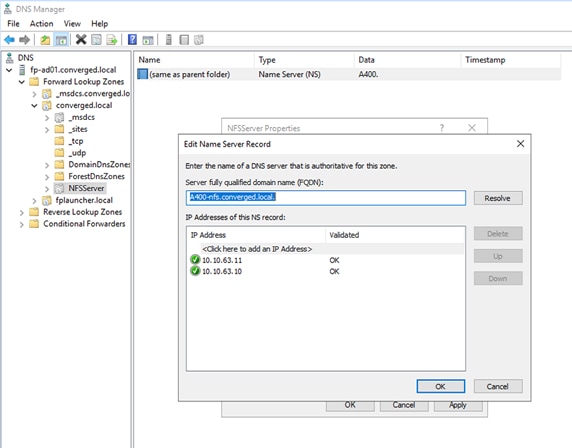
Cisco UCS Configuration
Cisco UCS Base Configuration
This FlexPod deployment explains the configuration steps for the Cisco UCS 6454 Fabric Interconnects (FI) in a design that will support FC SAN boot.
If setting up a system with iSCSI boot, the sections with (FCP) in the heading can be skipped and then complete the Cisco UCS iSCSI Configuration section in the Appendix.
Perform Initial Setup of Cisco UCS 6454 Fabric Interconnects for FlexPod Environments
This section provides the detailed procedures for configuring the Cisco Unified Computing System (Cisco UCS) for use in a FlexPod environment.
![]() These steps are necessary to provision the Cisco UCS B-Series and C-Series servers and should be followed precisely to avoid improper configuration.
These steps are necessary to provision the Cisco UCS B-Series and C-Series servers and should be followed precisely to avoid improper configuration.
Cisco UCS Fabric Interconnect A
To configure the Cisco UCS for use in a FlexPod environment in ucsm managed mode, follow these steps:
1. Connect to the console port on the first Cisco UCS fabric interconnect:
Enter the configuration method. (console/gui) ? console
Enter the management mode. (ucsm/intersight)? ucsm
Enter the setup mode; setup newly or restore from backup. (setup/restore) ? setup
You have chosen to setup a new Fabric interconnect in “ucsm” managed mode. Continue? (y/n): y
Enforce strong password? (y/n) [y]: Enter
Enter the password for "admin": <password>
Confirm the password for "admin": <password>
Is this Fabric interconnect part of a cluster(select 'no' for standalone)? (yes/no) [n]: y
Enter the switch fabric (A/B) []: A
Enter the system name: <ucs-cluster-name>
Physical Switch Mgmt0 IP address : <ucsa-mgmt-ip>
Physical Switch Mgmt0 IPv4 netmask : <ucsa-mgmt-mask>
IPv4 address of the default gateway : <ucsa-mgmt-gateway>
Cluster IPv4 address : <ucs-cluster-ip>
Configure the DNS Server IP address? (yes/no) [n]: y
DNS IP address : <dns-server-1-ip>
Configure the default domain name? (yes/no) [n]: y
Default domain name : <ad-dns-domain-name>
Join centralized management environment (UCS Central)? (yes/no) [n]: Enter
Apply and save the configuration (select 'no' if you want to re-enter)? (yes/no): yes
Cisco UCS Fabric Interconnect B
To configure the Cisco UCS for use in a FlexPod environment, follow these steps:
1. Connect to the console port on the second Cisco UCS fabric interconnect:
Enter the configuration method. (console/gui) ? console
Installer has detected the presence of a peer Fabric interconnect. This Fabric interconnect will be added to the cluster. Continue (y/n) ? y
Enter the admin password of the peer Fabric interconnect: <password>
Connecting to peer Fabric interconnect... done
Retrieving config from peer Fabric interconnect... done
Peer Fabric interconnect Mgmt0 IPv4 Address: <ucsa-mgmt-ip>
Peer Fabric interconnect Mgmt0 IPv4 Netmask: <ucsa-mgmt-mask>
Cluster IPv4 address : <ucs-cluster-ip>
Peer FI is IPv4 Cluster enabled. Please Provide Local Fabric Interconnect Mgmt0 IPv4 Address
Physical Switch Mgmt0 IP address : <ucsb-mgmt-ip>
Local fabric interconnect model(UCS-FI-6454)
Peer fabric interconnect is compatible with the local fabric interconnect. Continuing with the installer...
Apply and save the configuration (select 'no' if you want to re-enter)? (yes/no): yes
2. Wait for the login prompt for UCS Fabric Interconnect B before proceeding to the next section.
Cisco UCS Setup
To log into the Cisco Unified Computing System (Cisco UCS) environment, follow these steps:
1. Open a web browser and navigate to the Cisco UCS fabric interconnect cluster address.
![]() You may need to wait at least 5 minutes after configuring the second fabric interconnect for Cisco UCS Manager to open.
You may need to wait at least 5 minutes after configuring the second fabric interconnect for Cisco UCS Manager to open.
2. Click the Launch UCS Manager link to launch Cisco UCS Manager.
3. If prompted to accept security certificates, accept as necessary.
4. When prompted, enter admin for the user name and enter the administrative password.
5. Click Login to log into Cisco UCS Manager.
To enable anonymous reporting, follow this step:
1. In the Anonymous Reporting window, choose whether to send anonymous data to Cisco for improving future products. If you choose Yes, enter the IP address of your SMTP Server. Click OK.
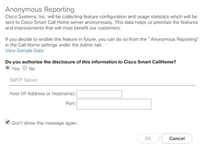
Upgrade Cisco UCS Manager Software to Version 4.1(2b)
This document assumes the use of Cisco UCS 4.1(2b). To upgrade the Cisco UCS Manager software and the Cisco UCS Fabric Interconnect software to version 4.1(2b), refer to Cisco UCS Manager Install and Upgrade Guides.
Cisco Intersight can also be used to upgrade the Cisco UCS Infrastructure (Cisco UCS Manager, Cisco UCS Fabric Interconnects, and Cisco UCS Fabric Extenders) to version 4.1(2b). Before the upgrade can be done from Cisco Intersight, the UCS cluster will need to be claimed into Intersight. Please see the Cisco Intersight section in the FlexPod Management Tools section of this document. For the Cisco Intersight-based upgrade procedure, please see https://intersight.com/help/features#firmware_upgrade. This upgrade does require interacting with Cisco UCS Manager to reboot the Primary Fabric Interconnect when upgrading. Because the Cisco UCS servers are not yet connected to the Cisco UCS Infrastructure, the servers will not be upgraded using Cisco Intersight. However, the Cisco UCS B and C-Series 4.1(2b) bundles need to be manually downloaded to the Cisco UCS system.
It is highly recommended by Cisco to configure Call Home in Cisco UCS Manager. Configuring Call Home will accelerate the resolution of support cases. To configure Call Home, follow these steps:
1. In Cisco UCS Manager, click Admin.
2. Choose All > Communication Management > Call Home.
3. Change the State to On.
4. Fill in all the fields according to your Management preferences and click Save Changes and OK to complete configuring Call Home.
To synchronize the Cisco UCS environment to the NTP servers in the Nexus switches, follow these steps:
1. In Cisco UCS Manager, click Admin.
2. Expand All > Time Zone Management.
3. Choose Timezone.
4. In the Properties pane, choose the appropriate time zone in the Timezone menu.
5. Click Save Changes and then click OK.
6. Click Add NTP Server.
7. Enter <nexus-A-mgmt0-ip> and click OK. Click OK on the confirmation.
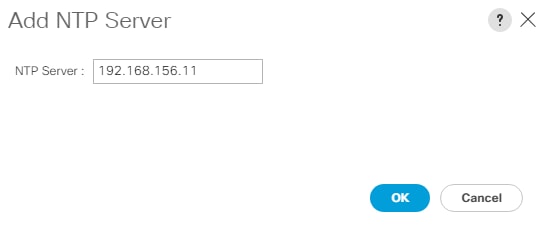
![]() We used the Nexus switch mgmt0 interface IP here because it is in the same L2 domain for the UCS mgmt0 IPs. We could also use the Nexus NTP IPs, but that traffic would then have to pass through an L3 router.
We used the Nexus switch mgmt0 interface IP here because it is in the same L2 domain for the UCS mgmt0 IPs. We could also use the Nexus NTP IPs, but that traffic would then have to pass through an L3 router.
8. Click Add NTP Server.
9. Enter <nexus-B-mgmt0-ip> and click OK, then click OK again.
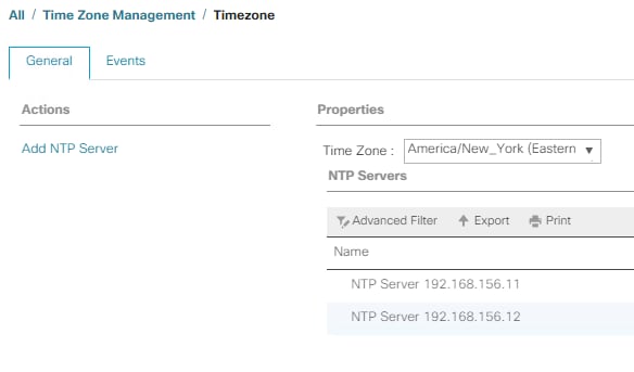
10. Add Additional DNS Server(s)
To add one or more additional DNS servers to the UCS environment, follow these steps:
11. In Cisco UCS Manager, click Admin.
12. Expand All > Communications Management.
13. Choose DNS Management.
14. In the Properties pane, choose Specify DNS Server.
15. Enter the IP address of the additional DNS server.
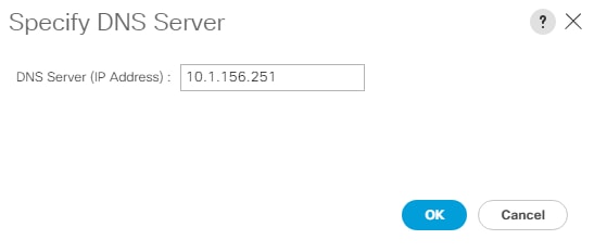
16. Click OK and then click OK again. Repeat this process for any additional DNS servers.
Add an Additional Administrative User
To add an additional locally authenticated Administrative user (flexadmin) to the Cisco UCS environment in case issues arise with the admin user, follow these steps:
1. In Cisco UCS Manager, click Admin.
2. Expand User Management > User Services > Locally Authenticated Users.
3. Right-click Locally Authenticated Users and choose Create User.
4. In the Create User fields it is only necessary to fill in the Login ID, Password, and Confirm Password fields. Fill in the Create User fields according to your local security policy.
5. Leave the Account Status field set to Active.
6. Set Account Expires according to your local security policy.
7. Under Roles, choose admin.
8. Leave Password Required selected for the SSH Type field.
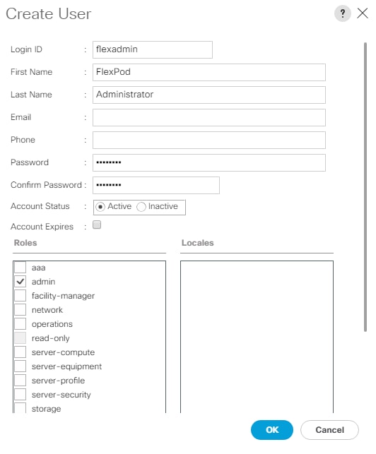
9. Click OK and then click OK again to complete adding the user.
Configure Unified Ports (FCP)
Fibre Channel port configurations differ between the Cisco UCS 6454, 6332-16UP and the 6248UP fabric interconnects. All fabric interconnects have a slider mechanism within the Cisco UCS Manager GUI interface, but the fibre channel port selection options for the 6454 are from the first 16 ports starting from the first port and configured in increments of 4 ports from the left. For the 6332-16UP the port selection options are from the first 16 ports starting from the first port, and configured in increments of the first 6, 12, or all 16 of the unified ports. With the 6248UP, the port selection options will start from the right of the 32 fixed ports, or the right of the 16 ports of the expansion module, going down in contiguous increments of 2. The remainder of this section shows configuration of the 6454. Modify as necessary for the 6332-16UP or 6248UP.
To enable the fibre channel ports, follow these steps for the 6454:
1. In Cisco UCS Manager, click Equipment.
2. Choose Equipment > Fabric Interconnects > Fabric Interconnect B (subordinate).
3. Choose Configure Unified Ports.
4. Click Yes on the pop-up window warning that changes to the fixed module will require a reboot of the fabric interconnect and changes to the expansion module will require a reboot of that module.
5. Within the Configured Fixed Ports pop-up window move the gray slider bar from the left to the right to choose either 4, 8, 12, or 16 ports to be set as FC Uplinks.
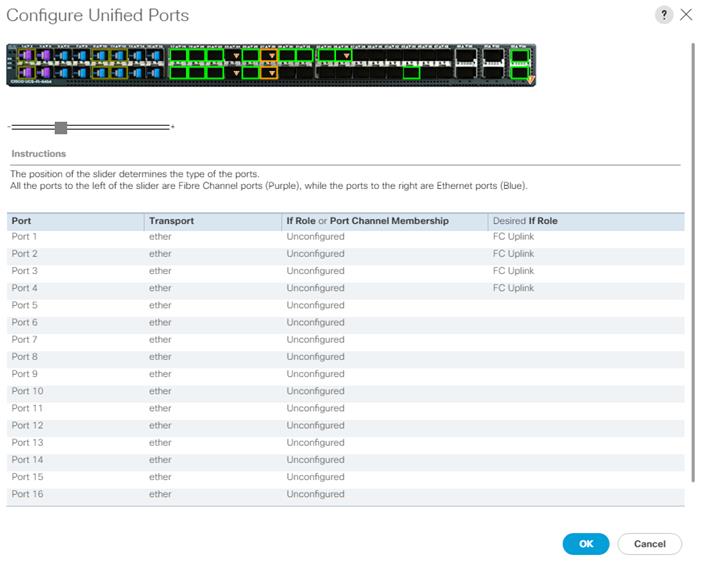
6. Click OK, then click Yes, then click OK to continue.
7. Choose Equipment > Fabric Interconnects > Fabric Interconnect A (primary).
8. Choose Configure Unified Ports.
9. Click Yes on the pop-up window warning that changes to the fixed module will require a reboot of the fabric interconnect and changes to the expansion module will require a reboot of that module.
10. Within the Configured Fixed Ports pop-up window move the gray slider bar from the left to the right to choose either 4 or 8 ports to be set as FC Uplinks.
11. Click OK, then click Yes, then OK to continue.
12. Wait for both Fabric Interconnects to reboot.
13. Log back into Cisco UCS Manager.
Setting the discovery policy simplifies the addition of Cisco UCS B-Series chassis and of additional fabric extenders for further Cisco UCS C-Series connectivity. To modify the chassis discovery policy, follow these steps:
1. In Cisco UCS Manager, click Equipment and choose the Policies tab.
2. Under Global Policies, set the Chassis/FEX Discovery Policy to match the minimum number of ports that are cabled between the chassis or fabric extenders (FEXes) and the fabric interconnects.
3. If varying numbers of links between chassis and the Fabric Interconnects will be used, set Action to 2 Link, the minimum recommended number of links for a FlexPod.
4. On the 6454 Fabric Interconnects, the Link Grouping Preference is automatically set to Port Channel and is greyed out. On a 6400 Series or 6200 Series Fabric Interconnect, set the Link Grouping Preference to Port Channel. If Backplane Speed Preference appears, leave it set at 40G.
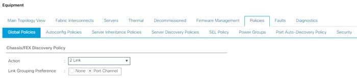
5. If any changes have been made, click Save Changes, and then click OK.
Enable Port Auto-Discovery Policy
Setting the port auto-discovery policy enables automatic discovery of Cisco UCS B-Series chassis server ports. To modify the port auto-discovery policy, follow these steps:
1. In Cisco UCS Manager, click Equipment, choose All > Equipment in the Navigation Pane, and choose the Policies tab.
2. Under Port Auto-Discovery Policy, set Auto Configure Server Port to Enabled.
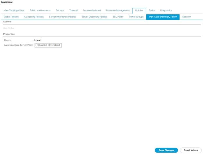
3. Click Save Changes and then OK.
Enable Server and Uplink Ports
To enable and verify server and uplink ports, follow these steps:
1. In Cisco UCS Manager, click Equipment.
2. Expand Equipment > Fabric Interconnects > Fabric Interconnect A (primary) > Fixed Module.
3. Expand and choose Ethernet Ports.
4. Verify that all ports connected to UCS chassis and rack mounts are configured as Server ports and have a status of Up.
5. If any rack mount ports are missing, choose the ports that are connected to Cisco FEXes and direct connect Cisco UCS C-Series servers, right-click them, and choose Configure as Server Port.
6. Click Yes to confirm server ports and click OK.
7. Verify that the ports connected to the chassis, C-series servers and Cisco FEX are now configured as server ports.
8. Choose the ports that are connected to the Cisco Nexus switches, right-click them, and choose Configure as Uplink Port.
9. Click Yes to confirm uplink ports and click OK.
10. Choose Equipment > Fabric Interconnects > Fabric Interconnect B (subordinate) > Fixed Module.
11. Expand and choose Ethernet Ports.
12. Verify that all ports connected to UCS chassis and rack mounts are configured as Server ports and have a status of Up.
13. If any rack mount ports are missing, choose the ports that are connected to Cisco FEXes and direct connect C-series servers, right-click them, and choose Configure as Server Port.
14. Click Yes to confirm server ports and click OK.
15. Verify that the ports connected to the chassis, C-series servers and Cisco FEX are now configured as server ports.
16. Choose the ports that are connected to the Cisco Nexus switches, right-click them, and choose Configure as Uplink Port.
17. Click Yes to confirm the uplink ports and click OK.
Enable Info Policy for Neighbor Discovery
Enabling the info policy enables Fabric Interconnect neighbor information to be displayed. To modify the info policy, follow these steps:
1. In Cisco UCS Manager, click Equipment, choose All > Equipment in the Navigation Pane, and choose the Policies tab on the right.
2. Under Global Policies, scroll down to Info Policy and choose Enabled for Action.

3. Click Save Changes and then click OK.
4. Under Equipment, choose Fabric Interconnect A or B. On the right, choose the Neighbors tab. CDP information is shown under the LAN tab and LLDP information is shown under the LLDP tab.
Acknowledge Cisco UCS Chassis and FEX
To acknowledge all Cisco UCS chassis and any external FEX modules, follow these steps:
1. In Cisco UCS Manager, click Equipment.
2. Expand Chassis and choose each chassis that is listed.
3. Right-click each chassis and choose Acknowledge Chassis.

4. Click Yes and then click OK to complete acknowledging the chassis.
5. If Nexus FEXes are part of the configuration, expand Rack Mounts and FEX.
6. Right-click each FEX that is listed and choose Acknowledge FEX.
7. Click Yes and then click OK to complete acknowledging the FEX.
To this point in the Cisco UCS deployment, all items have been deployed at the root level in Cisco UCS Manager. To allow Cisco UCS to be shared among different projects, you need to create Cisco UCS Organizations. In this validation, the organization for this FlexPod deployment is FlexPod. To create an organization, follow these steps:
1. In Cisco UCS Manager, click Servers.
2. In the Navigation Pane, expand Servers > Service Profiles.
3. Right-click root under Service Profiles and choose Create Organization.
4. Provide a name for the Organization to indicate this FlexPod deployment and optionally provide a Description.
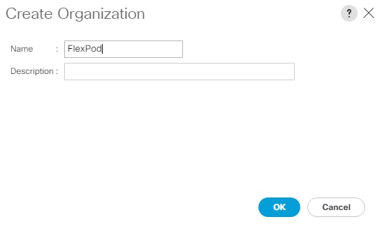
5. Click OK then click OK again to complete creating the organization.
Create a WWNN Pool for FC Boot (FCP)
In this FlexPod implementation, a WWNN pool is created at the root organization level to avoid WWNN address pool overlaps. If your deployment plan calls for different WWNN ranges in different UCS organizations, place the WWNN pool at the organizational level. To configure the necessary WWNN pool for the Cisco UCS environment, follow these steps on Cisco UCS Manager.
1. Click SAN.
2. Click Pools > root.
3. Right-click WWNN Pools under the root organization.
4. Click Create WWNN Pool to create the WWNN pool.
5. Enter WWNN-Pool for the name of the WWNN pool.
6. Optional: Enter a description for the WWNN pool.
7. Click Sequential for Assignment Order.
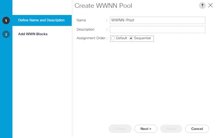
8. Click Next.
9. Click Add.
10. Modify the From field as necessary for the Cisco UCS Environment.
![]() Modifications of the WWNN block, as well for the WWPN and MAC Addresses, can convey identifying information for the Cisco UCS domain. Within the From field in our example, the sixth and seventh octets were changed from 00:00 to A1:30 to represent these WWNNs being in the A13 cabinet.
Modifications of the WWNN block, as well for the WWPN and MAC Addresses, can convey identifying information for the Cisco UCS domain. Within the From field in our example, the sixth and seventh octets were changed from 00:00 to A1:30 to represent these WWNNs being in the A13 cabinet.
![]() When there are multiple UCS domains sitting in adjacency, it is important that these blocks; the WWNN, WWPN, and MAC, hold differing values between each set.
When there are multiple UCS domains sitting in adjacency, it is important that these blocks; the WWNN, WWPN, and MAC, hold differing values between each set.
11. Specify a size of the WWNN block sufficient to support the available server resources. In this example, with the WWNN block modification, a maximum of 256 addresses are available.
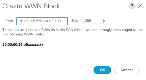
12. Click OK.
13. Click Finish and click OK to complete creating the WWNN pool.
Create WWPN Pools (FCP)
In this FlexPod implementation, WWPN address pools are created at the root organization level to avoid WWPN address pool overlaps. If your deployment plan calls for different WWPN address ranges in different UCS organizations, place the WWPN pools at the organizational level. To configure the necessary WWPN pools for the Cisco UCS environment, follow these steps:
1. In Cisco UCS Manager, click SAN.
2. Click Pools > root.
![]() In this procedure, two WWPN pools are created, one for each switching fabric.
In this procedure, two WWPN pools are created, one for each switching fabric.
3. Right-click WWPN Pools under the root organization.
4. Click Create WWPN Pool to create the WWPN pool.
5. Enter WWPN-Pool-A for the name of the WWPN pool.
6. Optional: Enter a description for the WWPN pool.
7. Click Sequential for Assignment Order.
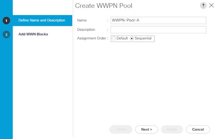
8. Click Next.
9. Click Add.
10. Specify a starting WWPN.
![]() For the FlexPod solution, the recommendation is to place A in the next-to-last octet of the starting WWPN to identify all of the WWPNs as fabric A addresses. Merging this with the pattern we used for the WWNN we see a WWPN block starting with 20:00:00:25:B5:A1:3A:00
For the FlexPod solution, the recommendation is to place A in the next-to-last octet of the starting WWPN to identify all of the WWPNs as fabric A addresses. Merging this with the pattern we used for the WWNN we see a WWPN block starting with 20:00:00:25:B5:A1:3A:00
11. Specify a size for the WWPN pool that is sufficient to support the available blade or server resources remembering that servers could have multiple vHBAs and unassociated service profiles could be created. In this example, with the WWPN block modification, a maximum of 256 addresses are available.
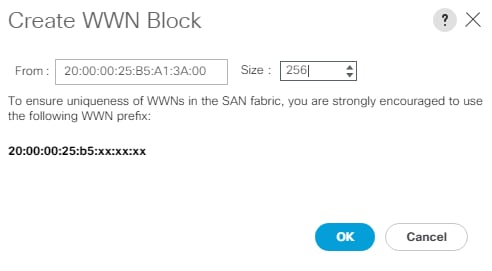
12. Click OK.
13. Click Finish.
14. In the confirmation message, click OK.
15. Right-click WWPN Pools under the root organization.
16. Click Create WWPN Pool to create the WWPN pool.
17. Enter WWPN-Pool-B for the name of the WWPN pool.
18. Optional: Enter a description for the WWPN pool.
19. Click Sequential for Assignment Order.
20. Click Next.
21. Click Add.
22. Specify a starting WWPN.
![]() For the FlexPod solution, the recommendation is to place B in the next-to-last octet of the starting WWPN to identify all of the WWPNs as fabric B addresses. Merging this with the pattern we used for the WWNN we see a WWPN block starting with 20:00:00:25:B5:A1:3B:00.
For the FlexPod solution, the recommendation is to place B in the next-to-last octet of the starting WWPN to identify all of the WWPNs as fabric B addresses. Merging this with the pattern we used for the WWNN we see a WWPN block starting with 20:00:00:25:B5:A1:3B:00.
23. Specify a size for the WWPN address pool that is sufficient to support the available blade or server resources remembering that servers could have multiple vHBAs and unassociated service profiles could be created. In this example, with the WWPN block modification, a maximum of 256 addresses are available.
24. Click OK.
25. Click Finish.
26. In the confirmation message, click OK.
Create VSANs (FCP)
To configure the necessary virtual storage area networks (VSANs) for the FlexPod Organization in the Cisco UCS environment, follow these steps:
1. In Cisco UCS Manager, click SAN.
2. In this procedure, two VSANs are created, one for each SAN switching fabric.
3. Click SAN > SAN Cloud.
4. Right-click VSANs.
5. Click Create VSAN.
6. Enter VSAN-A for the name of the VSAN to be used for Fabric A.
7. Leave FC Zoning set at Disabled.
8. Click Fabric A.
9. Enter a unique VSAN ID and a corresponding FCoE VLAN ID that matches the configuration in the MDS switch for Fabric A. It is recommended to use the same ID for both parameters and to use something other than 1.
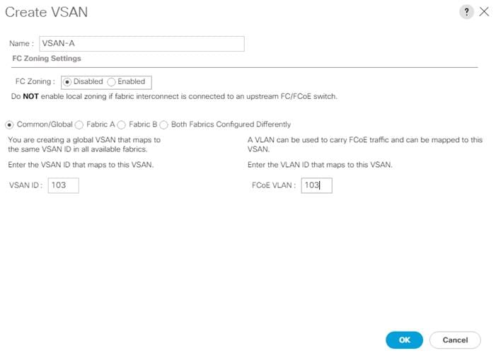
10. Click OK and then click OK again.
11. Under SAN Cloud, right-click VSANs.
12. Click Create VSAN.
13. Enter VSAN-B for the name of the VSAN to be used for Fabric B.
14. Leave FC Zoning set at Disabled.
15. Click Fabric B.
16. Enter a unique VSAN ID and a corresponding FCoE VLAN ID that matches the configuration in the MDS switch for Fabric B. It is recommended use the same ID for both parameters and to use something other than 1.
17. Click OK and then click OK again.
Enable FC Uplink VSAN Trunking (FCP)
To enable VSAN trunking on the FC Uplinks in the Cisco UCS environment, follow these steps:
![]() Enabling VSAN trunking is optional. It is important that the Cisco Nexus 93180YC-FX VSAN trunking configuration match the configuration set in Cisco UCS Manager.
Enabling VSAN trunking is optional. It is important that the Cisco Nexus 93180YC-FX VSAN trunking configuration match the configuration set in Cisco UCS Manager.
1. In Cisco UCS Manager, click SAN.
2. Expand SAN > SAN Cloud.
3. Click Fabric A and in the Actions pane click Enable FC Uplink Trunking.
4. Click Yes on the Confirmation and Warning.
5. Click OK.
6. Click Fabric B and in the Actions pane click Enable FC Uplink Trunking.
7. Click Yes on the Confirmation and Warning.
8. Click OK.
Create FC Uplink Port Channels (FCP)
To create the FC Uplink Port Channels and assign the appropriate VSANs to them for the Cisco UCS environment, follow these steps:
1. In Cisco UCS Manager, click SAN.
2. Click SAN > SAN Cloud.
3. Expand Fabric A and choose FC Port Channels.
4. Right-click FC Port Channels and click Create FC Port Channel.
5. Set a unique ID for the port channel and provide a unique name for the port channel.
6. Click Next.
7. Click the appropriate Port Channel Admin Speed.
8. Click the ports connected to Cisco MDS 9132T A and use >> to add them to the port channel.
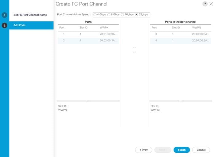
9. Click Finish to complete creating the port channel.
10. Click OK on the confirmation.
11. Under FC Port-Channels, click the newly created port channel.
12. From the drop-down list to choose VSAN-A.
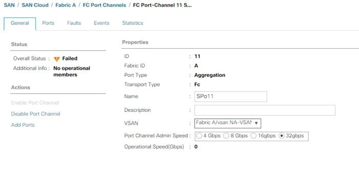
13. Click Save Changes to assign the VSAN.
14. Click OK.
16. Expand Fabric B and choose FC Port Channels.
17. Right-click FC Port Channels and click Create FC Port Channel.
18. Set a unique ID for the port channel and provide a unique name for the port channel.
19. Click Next.
20. Choose the ports connected to Cisco MDS 9132T B and use >> to add them to the port channel.
21. Click Finish to complete creating the port channel.
22. Click OK on the confirmation.
23. Under FC Port-Channels, click the newly created port channel.
24. In the right pane, from the drop-down list click VSAN-B.
25. Click Save Changes to assign the VSAN.
26. Click OK.
27. Under FC Port Channels, expand the newly created FC Port-Channel. Under the FC Port-Channel click the first FC Interface. Enter a User Label to indicate the connectivity on the Nexus 93180YC-FX switch, such as <nexus-B-hostname>:fc1/5. Click Save Changes and OK. Repeat this process for the other FC Interface.
Disable Unused FC Uplink Ports (FCP)
When Unified Ports were configured earlier in this procedure, on the Cisco UCS 6454 FI and the Cisco UCS 6332-16UP FI, FC ports were configured in groups. Because of this group configuration, some FC ports are unused and need to be disabled to prevent alerts. To disable the unused FC ports 1 and 2 on the Cisco UCS 6454 FIs, follow these steps:
1. In Cisco UCS Manager, click SAN.
2. In the Navigation Pane, expand SAN > SAN Cloud > Fabric A > Uplink FC Interfaces.
3. Right-click FC Interface 1/1 and click Disable Interface.
4. Click Yes and OK to complete disabling FC Interface 1/1.
5. Repeat this process to disable FC Interface 1/2.
6. In the Navigation Pane, go to SAN > SAN Cloud > Fabric B > Uplink FC Interfaces.
7. Right-click FC Interface 1/1 and click Disable Interface.
8. Click Yes and then click OK to complete disabling FC Interface 1/1.
9. Repeat steps 1-8 to disable FC Interface 1/2.
Create vHBA Templates (FCP)
To create the necessary virtual host bus adapter (vHBA) templates for the Cisco UCS environment within the FlexPod organization, follow these steps:
1. In Cisco UCS Manager, click SAN.
2. Expand Policies > root > Sub-Organizations > FlexPod.
3. Right-click vHBA Templates under the FlexPod Organization.
4. Click Create vHBA Template.
5. Enter FCP-vHBA-A for the vHBA template name.
6. Keep Fabric A selected.
7. Leave Redundancy Type set to No Redundancy.
8. Choose VSAN-A.
9. Leave Initial Template for the Template Type.
10. Click WWPN-Pool-A for the WWPN Pool.
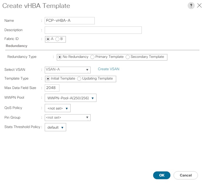
11. Click OK to create the vHBA template.
12. Click OK.
13. Right-click vHBA Templates under the FlexPod Organization.
14. Click Create vHBA Template.
15. Enter FCP-vHBA-B for the vHBA template name.
16. Click B for the Fabric ID.
17. Leave Redundancy Type set to No Redundancy.
18. Click VSAN-B.
19. Leave Initial Template for the Template Type.
20. Click WWPN-Pool-B for the WWPN Pool.
21. Click OK to create the vHBA template.
22. Click OK.
Create SAN Connectivity Policy (FCP)
To configure the necessary Infrastructure SAN Connectivity Policy within the FlexPod organization, follow these steps:
1. In Cisco UCS Manager, click SAN.
2. Go to SAN > Policies > root > Sub-Organizations > FlexPod.
3. Right-click SAN Connectivity Policies under the FlexPod Organization.
4. Click Create SAN Connectivity Policy.
5. Enter FC-Boot for the name of the policy.
6. Click the previously created WWNN-Pool for the WWNN Assignment.
7. Click Add to add a vHBA.
8. In the Create vHBA dialog box, enter FCP-Fabric-A for the name of the vHBA.
9. Click the Use vHBA Template checkbox.
10. In the vHBA Template list, choose FCP-vHBA-A.
11. In the Adapter Policy list, choose VMWare.
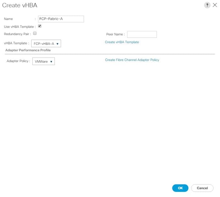
12. Click OK.
13. Click Add to add a second vHBA.
14. In the Create vHBA dialog box, enter FCP-Fabric-B for the name of the vHBA.
15. Click the Use vHBA Template checkbox.
16. In the vHBA Template list, choose FCP-vHBA-B.
17. In the Adapter Policy list, choose VMWare.
18. Click OK.
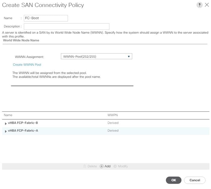
19. Click OK to create the SAN Connectivity Policy.
20. Click OK to confirm creation.
Add Block of IP Addresses for KVM Access
To create a block of IP addresses for in band server Keyboard, Video, Mouse (KVM) access in the Cisco UCS environment, follow these steps:
1. In Cisco UCS Manager, click LAN.
2. Expand Pools > root > IP Pools.
3. Right-click IP Pool ext-mgmt and choose Create Block of IPv4 Addresses.
4. Enter the starting IP address of the block, number of IP addresses required, and the subnet mask and gateway information. Optionally, enter the Primary and Secondary DNS server addresses.
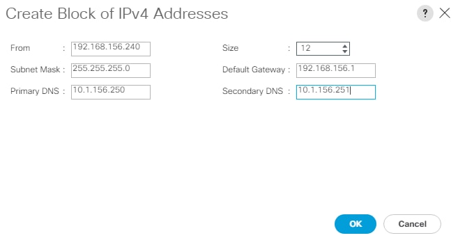
5. Click OK to create the block.
6. Click OK in the confirmation message.
Create Uplink Port Channels to Cisco Nexus Switches
To configure the necessary port channels out of the Cisco UCS environment, follow these steps:
1. In Cisco UCS Manager, click LAN.
![]() In this procedure, two port channels are created: one from fabric A to both Cisco Nexus switches and one from fabric B to both Cisco Nexus switches.
In this procedure, two port channels are created: one from fabric A to both Cisco Nexus switches and one from fabric B to both Cisco Nexus switches.
2. Under LAN > LAN Cloud, expand the Fabric A tree.
3. Right-click Port Channels under Fabric A.
4. Click Create Port Channel.
5. Enter 145 for the unique ID of the port channel.
6. Enter Po145-Nexus for the name of the port channel.
7. Click Next.
8. Click the uplink ports connected to the Nexus switches to be added to the port channel.
9. Click >> to add the ports to the port channel.
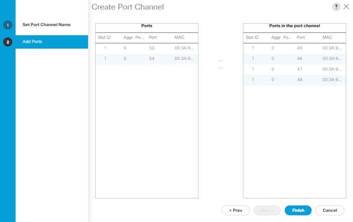
10. Click Finish to create the port channel.
11. Click OK.
12. In the navigation pane, under LAN > LAN Cloud > Fabric A > Port Channels, choose Port-Channel 145. Ensure Auto is selected for the Admin Speed. After a few minutes, verify that the Overall Status is Up, and the Operational Speed is correct.
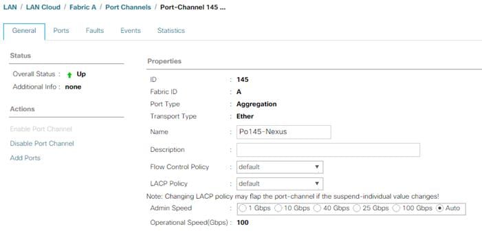
13. In the navigation pane, under LAN > LAN Cloud, expand the Fabric B tree.
14. Right-click Port Channels under Fabric B.
15. Click Create Port Channel.
16. Enter 146 for the unique ID of the port channel.
17. Enter Po146-Nexus for the name of the port channel.
18. Click Next.
19. Click the ports connected to the Nexus switches to be added to the port channel:
20. Click >> to add the ports to the port channel.
21. Click Finish to create the port channel.
22. Click OK.
23. In the navigation pane, under LAN > LAN Cloud > Fabric B > Port Channels, Click Port-Channel 146. Ensure Auto is selected for the Admin Speed. After a few minutes, verify that the Overall Status is Up, and the Operational Speed is correct.
24. In the navigation pane, under LAN > LAN Cloud > Fabric A > Port Channels, expand Port-Channel 145. Under Port-Channel 145, choose Eth Interface 1/45. In the center pane under Properties, enter a User Label to indicate the port connectivity, such as <nexus-a-hostname>:Eth1/21. Click Save Changes and then click OK. Repeat this process for the remaining seven uplink ports.
Add UDLD to Uplink Port Channels
To configure the unidirectional link detection (UDLD) on the Uplink Port Channels to the Nexus switches for fibre optic connections, follow these steps:
1. In Cisco UCS Manager, click LAN.
2. Expand Policies > LAN Cloud > UDLD Link Policy.
3. Right-click UDLD Link Policy and choose Create UDLD Link Policy.
4. Name the Policy UDLD-Normal and choose Enabled for the Admin State and Normal for the Mode.
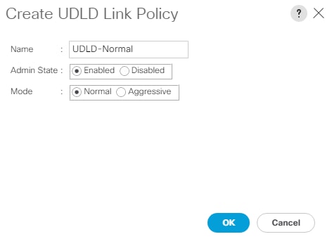
5. Click OK, then click OK again to complete creating the policy.
6. Expand Policies > LAN Cloud > Link Profile.
7. Right-click Link Profile and choose Create Link Profile.
8. Name the Profile UDLD-Normal and choose the UDLD-Normal Link Policy created above.
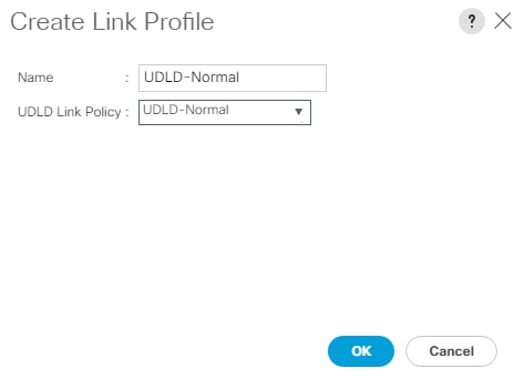
9. Click OK, then click OK again to complete creating the profile.
10. In the navigation pane, under LAN > LAN Cloud > Fabric A > Port Channels, expand Port-Channel 145. Click the first Eth Interface under Port-Channel 145. From the drop-down list, click the UDLD-Normal Link Profile previously created, click Save Changes, and then click OK. Repeat this process for each Eth Interface under Port-Channel 145 and for each Eth Interface under Port-Channel 146 on Fabric B.
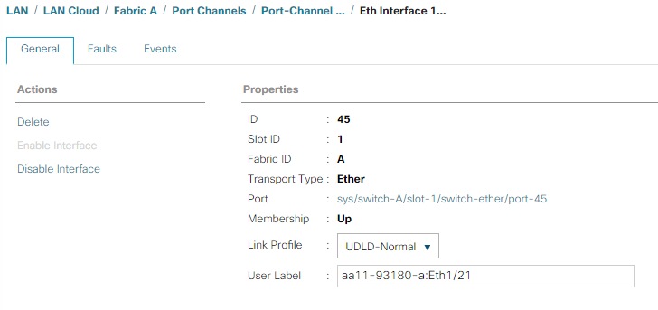
Set Jumbo Frames in Cisco UCS Fabric
Jumbo Frames are used in FlexPod for the NFS and iSCSI storage protocols. The normal best practice in FlexPod has been to set the MTU of the Best Effort QoS System Class in Cisco UCS Manager to 9216 for Jumbo Frames. In the Cisco UCS 6454 Fabric Interconnect with Cisco UCS Manager version 4.0 software the MTU for the Best Effort QoS System Class is fixed at normal and cannot be changed. With this setting of normal in the 6454, Jumbo Frames can pass through the Cisco UCS fabric without being dropped. In Cisco UCS Manager version 4.1, the MTU for the Best Effort QoS System Class is again settable. To configure jumbo frames in the UCS fabric, follow these steps:
1. In Cisco UCS Manager, click LAN.
2. Go to LAN > LAN Cloud > QoS System Class.
3. In the right pane, click the General tab.
4. On the Best Effort row, enter 9216 in the box under the MTU column.
5. Click Save Changes.
6. Click OK.
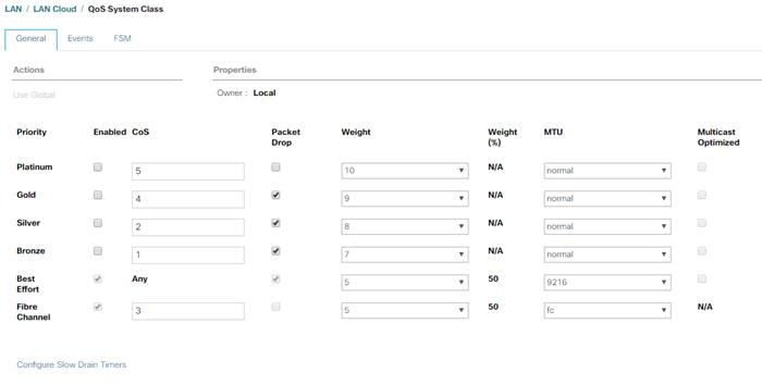
![]() Only the Fibre Channel and Best Effort QoS System Classes are enabled in this FlexPod implementation. The Cisco UCS and Cisco Nexus switches are intentionally configured this way so that all IP traffic within the FlexPod will be treated as Best Effort. Enabling the other QoS System Classes without having a comprehensive, end-to-end QoS setup in place can cause difficult to troubleshoot issues. For example, NetApp storage controllers by default mark IP-based, VLAN-tagged packets with a CoS value of 4. With the default configuration on the Nexus switches in this implementation, storage packets will pass through the switches and into the Cisco UCS Fabric Interconnects with CoS 4 set in the packet header. If the Gold QoS System Class in the Cisco UCS is enabled and the corresponding CoS value left at 4, these storage packets will be treated according to that class and if Jumbo Frames is being used for the storage protocols, but the MTU of the Gold QoS System Class is not set to Jumbo (9216), packet drops will occur. Note also that if the Platinum class is enabled, the MTU must be set to 9216 to use Jumbo Frames in that class.
Only the Fibre Channel and Best Effort QoS System Classes are enabled in this FlexPod implementation. The Cisco UCS and Cisco Nexus switches are intentionally configured this way so that all IP traffic within the FlexPod will be treated as Best Effort. Enabling the other QoS System Classes without having a comprehensive, end-to-end QoS setup in place can cause difficult to troubleshoot issues. For example, NetApp storage controllers by default mark IP-based, VLAN-tagged packets with a CoS value of 4. With the default configuration on the Nexus switches in this implementation, storage packets will pass through the switches and into the Cisco UCS Fabric Interconnects with CoS 4 set in the packet header. If the Gold QoS System Class in the Cisco UCS is enabled and the corresponding CoS value left at 4, these storage packets will be treated according to that class and if Jumbo Frames is being used for the storage protocols, but the MTU of the Gold QoS System Class is not set to Jumbo (9216), packet drops will occur. Note also that if the Platinum class is enabled, the MTU must be set to 9216 to use Jumbo Frames in that class.
To configure the necessary virtual local area networks (VLANs) for the Cisco UCS environment, follow these steps:
1. In Cisco UCS Manager, click LAN.
2. In this procedure, five unique VLANs are created. See Table2.
3. Expand LAN > LAN Cloud.
4. Right-click VLANs.
5. Choose Create VLANs.
6. Enter Native-VLAN for the name of the VLAN to be used for the native VLAN.
7. Keep the Common/Global option selected for the scope of the VLAN.
8. Enter the native VLAN ID.
9. Keep the Sharing Type as None.
10. Click OK and then click OK again.
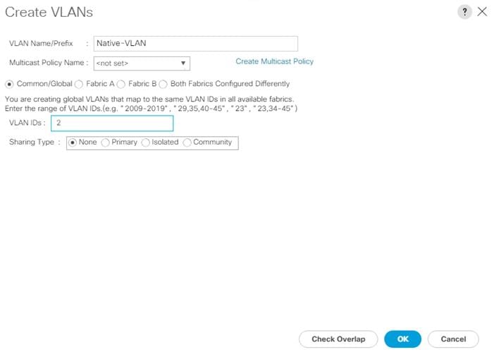
11. Expand the list of VLANs in the navigation pane, right-click the newly created Native-VLAN and choose Set as Native VLAN.
12. Click Yes and then click OK.
13. Right-click VLANs.
14. Click Create VLANs.
15. Enter IB-MGMT for the name of the VLAN to be used for management traffic.
16. Modify these VLAN names as necessary for your environment.
17. Keep the Common/Global option selected for the scope of the VLAN.
18. Enter the In-Band management VLAN ID.
19. Keep the Sharing Type as None.
20. Click OK, and then click OK again.
21. Right-click VLANs.
22. Click Create VLANs.
23. Enter Infra-NFS for the name of the VLAN to be used for NFS.
24. Keep the Common/Global option selected for the scope of the VLAN.
25. Enter the Infrastructure NFS VLAN ID.
26. Keep the Sharing Type as None.
27. Click OK, and then click OK again.
28. Right-click VLANs.
29. Click Create VLANs.
30. Enter vMotion for the name of the VLAN to be used for vMotion.
31. Keep the Common/Global option selected for the scope of the VLAN.
32. Enter the vMotion VLAN ID.
33. Keep the Sharing Type as None.
34. Click OK and then click OK again.
35. Click Create VLANs.
36. Enter VM-Traffic for the name of the VLAN to be used for VM Traffic.
37. Keep the Common/Global option selected for the scope of the VLAN.
38. Enter the VM-Traffic VLAN ID.
39. Keep the Sharing Type as None.
40. Click OK and then click OK again.
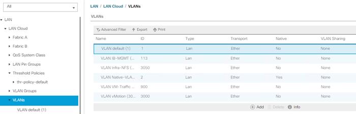
In this FlexPod implementation, MAC address pools are created at the root organization level to avoid MAC address pool overlaps. If your deployment plan calls for different MAC address ranges in different UCS organizations, place the MAC pools at the organizational level. To configure the necessary MAC address pools for the Cisco UCS environment, follow these steps:
1. In Cisco UCS Manager, click LAN.
2. Go to Pools > root.
![]() In this procedure, two MAC address pools are created, one for each switching fabric.
In this procedure, two MAC address pools are created, one for each switching fabric.
3. Right-click MAC Pools under the root organization.
4. Click Create MAC Pool to create the MAC address pool.
5. Enter MAC-Pool-A for the name of the MAC pool.
6. Optional: Enter a description for the MAC pool.
7. Click Sequential for the option for Assignment Order.
8. Click Next.
9. Click Add.
10. Specify a starting MAC address.
![]() For the FlexPod solution, the recommendation is to place A in the next-to-last octet of the starting MAC address to identify all of the MAC addresses as fabric A addresses. In our example, we have carried forward the example of also embedding the cabinet number information giving us 00:25:B5:A1:3A:00 as our first MAC address.
For the FlexPod solution, the recommendation is to place A in the next-to-last octet of the starting MAC address to identify all of the MAC addresses as fabric A addresses. In our example, we have carried forward the example of also embedding the cabinet number information giving us 00:25:B5:A1:3A:00 as our first MAC address.
11. Specify a size for the MAC address pool that is sufficient to support the available blade or server resources remembering that a server may contain multiple vNICs and that multiple unassociated Service Profiles can be created. In this example, with the MAC block modification, a maximum of 256 addresses are available.
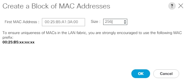
12. Click OK.
13. Click Finish.
14. In the confirmation message, click OK.
15. Right-click MAC Pools under the root organization.
16. Click Create MAC Pool to create the MAC address pool.
17. Enter MAC-Pool-B for the name of the MAC pool.
18. Optional: Enter a description for the MAC pool.
19. Choose Sequential for the option for Assignment Order.
20. Click Next.
21. Click Add.
22. Specify a starting MAC address.
![]() For the FlexPod solution, it is recommended to place B in the next to last octet of the starting MAC address to identify all the MAC addresses in this pool as fabric B addresses. Once again, we have carried forward our example of also embedding the cabinet number information giving us 00:25:B5:A1:3B:00 as our first MAC address.
For the FlexPod solution, it is recommended to place B in the next to last octet of the starting MAC address to identify all the MAC addresses in this pool as fabric B addresses. Once again, we have carried forward our example of also embedding the cabinet number information giving us 00:25:B5:A1:3B:00 as our first MAC address.
23. Specify a size for the MAC address pool that is sufficient to support the available blade or server resources remembering that a server may contain multiple vNICs and that multiple unassociated Service Profiles can be created. In this example, with the MAC block modification, a maximum of 256 addresses are available.
24. Click OK.
25. Click Finish.
26. In the confirmation message, click OK.
Create Network Control Policy for Cisco Discovery Protocol (CDP) and Link Layer Discovery Protocol (LLDP)
To create a network control policy that enables CDP and LLDP on server virtual network controller (vNIC) ports, follow these steps:
1. In Cisco UCS Manager, click LAN.
2. Expand Policies > root.
3. Right-click Network Control Policies.
4. Click Create Network Control Policy.
5. Enter Enable-CDP-LLDP for the policy name.
6. For CDP, Click the Enabled option.
7. For LLDP, scroll down and click Enabled for both Transmit and Receive.
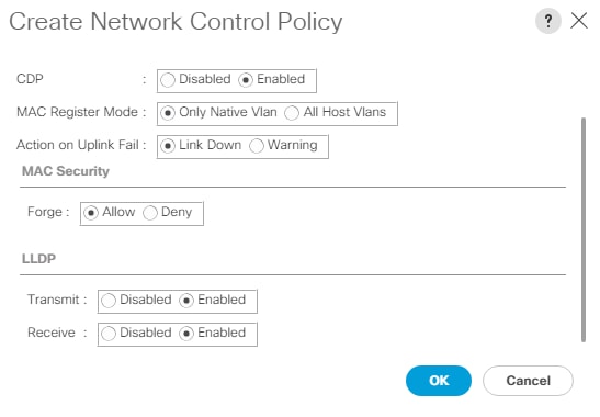
8. Click OK to create the network control policy.
9. Click OK.
To create multiple virtual network interface card (vNIC) templates within the FlexPod organization, follow these steps. A total of 4 vNIC Templates will be created. Two of the vNIC templates (vSwitch0-A and vSwitch0-B) will be created for vNICs to connect to VMware ESXi vSwitch0. vSwitch0 will have port groups for the IB-MGMT, Infra-NFS, vMotion, and VM-Traffic VLANs. The third and fourth vNIC templates (vDS0-A and vDS0-B) will be created for vNICs to connect to the VMware Virtual Distributed Switch (vDS0). The vDS will have port groups for the vMotion and VM-Traffic VLANs. The vMotion VLAN is being placed on both vSwitch0 and vDS0 so that the vMotion VMkernel port can initially be created on vSwitch0 then migrated to the vDS to allow QoS marking of vMotion packets to occur within the vDS if QoS policies need to be applied to vMotion in the future. Any tenant or application VLANs can be placed on the vDS in the future.
Create Infrastructure vNIC Templates
To create the infrastructure vNIC templates, follow these steps:
1. In Cisco UCS Manager, click LAN.
2. Go to Policies > root > Sub-Organizations > FlexPod.
3. Under the FlexPod Organization, right-click vNIC Templates.
4. Click Create vNIC Template.
5. Enter vSwitch0-A for the vNIC template name.
6. Keep Fabric A selected.
7. Do not select the Enable Failover checkbox.
8. Choose Primary Template for Redundancy Type.
9. Leave the Peer Redundancy Template set to <not set>.
10. Under Target, make sure that only the Adapter checkbox is selected.
11. Click Updating Template for the Template Type.
12. Under VLANs, choose the checkboxes for IB-MGMT, Infra-NFS, vMotion, and Native-VLAN VLANs.
13. Set Native-VLAN for the native VLAN.
14. Click vNIC Name for the CDN Source.
15. For MTU, enter 9000.
16. In the MAC Pool list, click MAC-Pool-A.
17. In the Network Control Policy list, click Enable-CDP-LLDP.
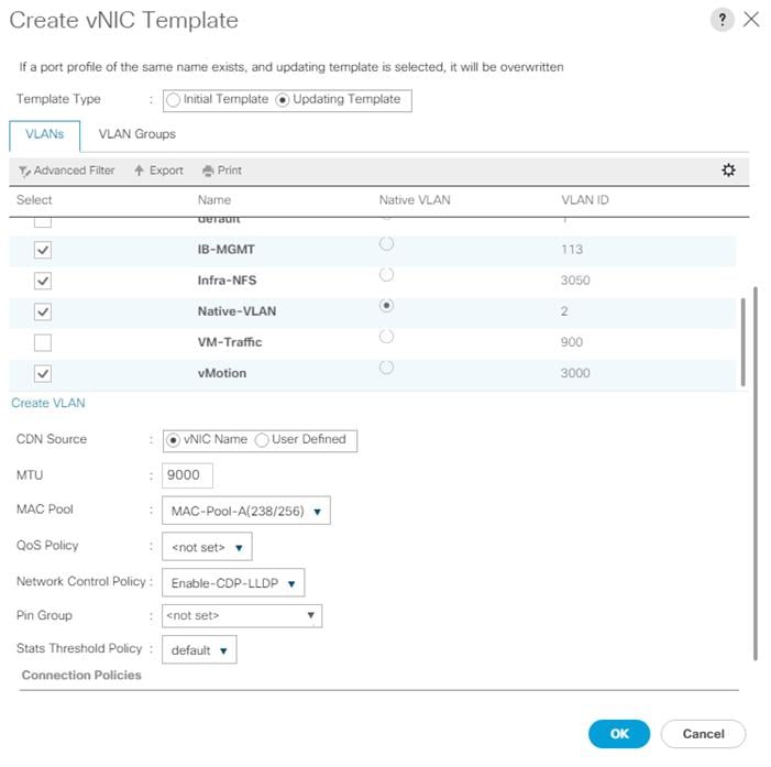
18. Click OK to create the vNIC template.
19. Click OK.
20. Under the FlexPod organization, right-click vNIC Templates.
21. Click Create vNIC Template.
22. Enter vSwitch0-B for the vNIC template name.
23. Click Fabric B.
24. Do not select the Enable Failover checkbox.
25. Set Redundancy Type to Secondary Template.
26. Click vSwitch0-A for the Peer Redundancy Template.
27. In the MAC Pool list, choose MAC-Pool-B.
28. The MAC Pool is all that needs to be selected for the Secondary Template, all other values will either be propagated from the Primary Template or set at default values.
29. Click OK to create the vNIC template.
30. Click OK.
31. Under the FlexPod Organization, right-click vNIC Templates.
32. Click Create vNIC Template.
33. Enter vDS0-A for the vNIC template name.
34. Keep Fabric A selected.
35. Do not select the Enable Failover checkbox.
36. Click Primary Template for Redundancy Type.
37. Leave the Peer Redundancy Template set to <not set>.
38. Under Target, make sure that only the Adapter checkbox is selected.
39. Click Updating Template for the Template Type.
40. Under VLANs, choose the checkboxes for vMotion, VM-Traffic, and Native-VLAN VLANs.
41. Set Native-VLAN for the native VLAN.
42. Click vNIC Name for the CDN Source.
43. For MTU, enter 9000.
44. In the MAC Pool list, choose MAC-Pool-A.
45. In the Network Control Policy list, choose Enable-CDP-LLDP.
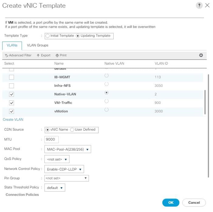
46. Click OK to create the vNIC template.
47. Click OK.
48. Under the FlexPod organization, right-click vNIC Templates.
49. Click Create vNIC Template.
50. Enter vDS0-B for the vNIC template name.
51. Click Fabric B.
52. Do not select the Enable Failover checkbox.
53. Set Redundancy Type to Secondary Template.
54. Click vDS0-A for the Peer Redundancy Template.
55. In the MAC Pool list, choose MAC-Pool-B.
![]() The MAC Pool is all that needs to be selected for the Secondary Template, all other values will either be propagated from the Primary Template or set at default values.
The MAC Pool is all that needs to be selected for the Secondary Template, all other values will either be propagated from the Primary Template or set at default values.
56. Click OK to create the vNIC template.
57. Click OK.
Create High Traffic VMware Adapter Policy
To create the optional VMware-High-Traffic Ethernet Adapter policy to provide higher vNIC performance, follow these steps:
![]() This Ethernet Adapter policy can be attached to vNICs when creating the LAN Connectivity policy for vNICs that have large amounts of traffic on multiple flows or TCP sessions. This policy provides more hardware receive queues handled by multiple CPUs to the vNIC.
This Ethernet Adapter policy can be attached to vNICs when creating the LAN Connectivity policy for vNICs that have large amounts of traffic on multiple flows or TCP sessions. This policy provides more hardware receive queues handled by multiple CPUs to the vNIC.
1. In Cisco UCS Manager, click Servers.
2. Expand Policies > root.
3. Right-click Adapter Policies and choose Create Ethernet Adapter Policy.
4. Name the policy VMware-HighTrf.
5. Expand Resources and set the values as shown below.
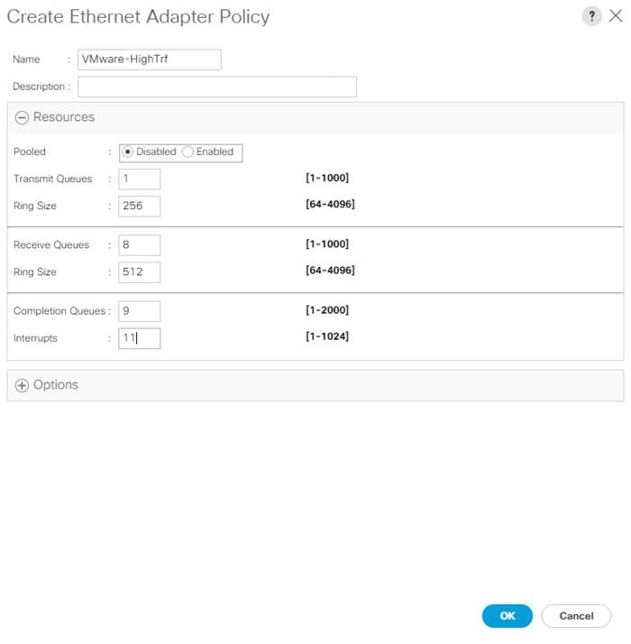
![]() In this policy, Receive Queues can be set to 1-16. Completion Queues = Transmit Queues + Receive Queues. Interrupts = Completion Queues + 2. For more information, see Cisco UCS Manager Network Management Guide, Release 4.1, Network-Related Policies.
In this policy, Receive Queues can be set to 1-16. Completion Queues = Transmit Queues + Receive Queues. Interrupts = Completion Queues + 2. For more information, see Cisco UCS Manager Network Management Guide, Release 4.1, Network-Related Policies.
![]() Although previous versions of this document set the Ring Sizes for the Transmit and Receive Queues to 4096, Tuning Guidelines for Cisco UCS Virtual Interface Cards states that the sizes should be increased only if packet drops are observed on the vNIC interfaces.
Although previous versions of this document set the Ring Sizes for the Transmit and Receive Queues to 4096, Tuning Guidelines for Cisco UCS Virtual Interface Cards states that the sizes should be increased only if packet drops are observed on the vNIC interfaces.
6. Expand Options and choose Enabled for Receive Side Scaling (RSS).
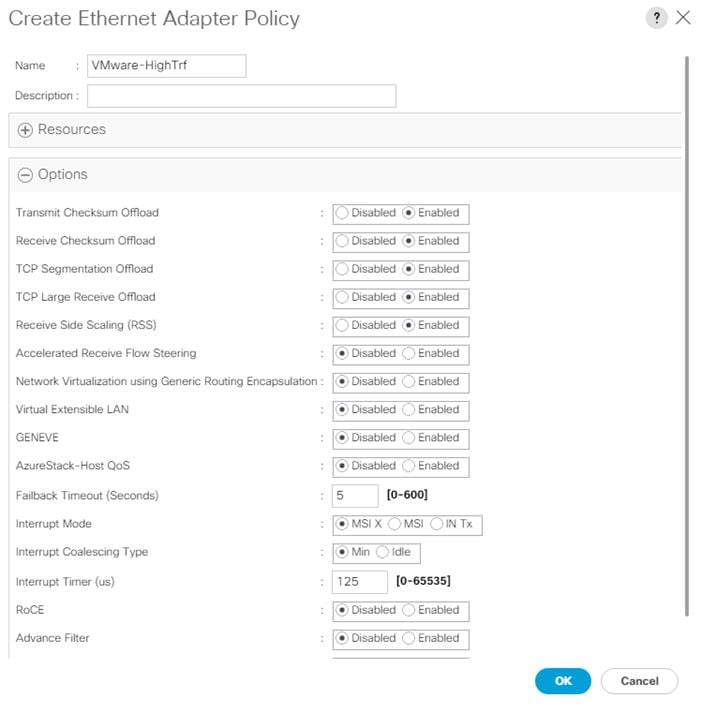
7. Click OK, then click OK again to complete creating the Ethernet Adapter Policy.
Create LAN Connectivity Policy for FC Boot (FCP)
To configure the necessary Infrastructure LAN Connectivity Policy within the FlexPod organization, follow these steps:
1. In Cisco UCS Manager, click LAN.
2. Go to LAN > Policies > root > Sub-Organizations > FlexPod.
3. Under the FlexPod Organization, right-click LAN Connectivity Policies.
4. Click Create LAN Connectivity Policy.
5. Enter FC-Boot for the name of the policy.
6. Click OK then click OK again to add the policy.
7. Go to LAN > Policies > root > Sub-Organizations > FlexPod > LAN Connectivity Policies, choose FC-Boot.
8. Click Add to add a vNIC.
9. In the Create vNIC dialog box, enter 00-vSwitch0-A for the name of the vNIC.
10. Click the Use vNIC Template checkbox.
11. In the vNIC Template list, choose vSwitch0-A.
12. In the Adapter Policy list, choose VMWare.
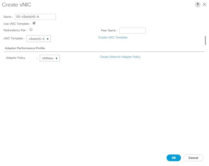
13. Click OK to add this vNIC to the policy.
14. Click Save Changes and OK.
15. Click Add to add another vNIC to the policy.
16. In the Create vNIC box, enter 01-vSwitch0-B for the name of the vNIC.
17. Check the box for the Use vNIC Template.
18. In the vNIC Template list, choose vSwitch0-B.
19. In the Adapter Policy list, choose VMWare.
20. Click OK to add the vNIC to the policy.
21. Click Save Changes and OK.
22. Click Add to add another vNIC to the policy.
23. In the Create vNIC dialog box, enter 02-vDS0-A for the name of the vNIC.
24. Click the Use vNIC Template checkbox.
25. In the vNIC Template list, choose vDS0-A.
26. In the Adapter Policy list, choose VMWare-HighTrf.
27. The VMware Adapter Policy can also be selected for this vNIC.
28. Click OK to add this vNIC to the policy.
29. Click Save Changes and OK.
30. Click Add to add another vNIC to the policy.
31. In the Create vNIC box, enter 03-vDS0-B for the name of the vNIC.
32. Choose the Use vNIC Template checkbox.
33. In the vNIC Template list, choose vDS0-B.
34. In the Adapter Policy list, choose VMWare-HighTrf.
35. Choose the same Adapter Policy that was selected for 02-Infra-vDS-A.
36. Click OK to add this vNIC to the policy.
37. Click Save Changes and then click OK.
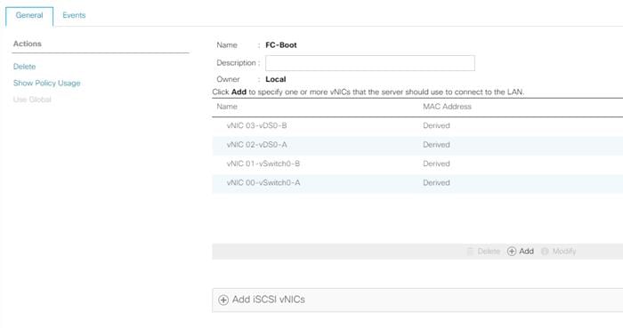
To configure the necessary server pool for the Cisco UCS environment in the FlexPod Organization, follow these steps:
![]() Consider creating unique server pools to achieve the granularity that is required in your environment.
Consider creating unique server pools to achieve the granularity that is required in your environment.
1. In Cisco UCS Manager, click Servers.
2. Expand Pools > root > Sub-Organizations > FlexPod.
3. Right-click Server Pools under the FlexPod Organization.
4. Choose Create Server Pool.
5. Enter Intel-Infra-Pool for the name of the server pool.
6. Optional: Enter a description for the server pool.
7. Click Next.
8. Choose three (or more) servers to be used for the VMware management cluster and click >> to add them to the Intel-Infra-Pool server pool.
![]() Although the VMware minimum host cluster size is two, in most use cases three servers are recommended.
Although the VMware minimum host cluster size is two, in most use cases three servers are recommended.
9. Click Finish.
To configure the necessary universally unique identifier (UUID) suffix pool for the Cisco UCS environment, follow these steps:
1. In Cisco UCS Manager, click Servers.
2. Go to Pools > root.
3. Right-click UUID Suffix Pools.
4. Click Create UUID Suffix Pool.
5. Enter UUID-Pool for the name of the UUID suffix pool.
6. Optional: Enter a description for the UUID suffix pool.
7. Keep the prefix at the derived option.
8. Click Sequential for the Assignment Order.
9. Click Next.
10. Click Add to add a block of UUIDs.
11. Keep the From field at the default setting.
12. Specify a size for the UUID block that is sufficient to support the available blade or server resources and the number of Service Profiles that will be created.
13. Click OK.
14. Click Finish.
15. Click OK.
Modify Default Host Firmware Package
Firmware management policies allow the administrator to choose the corresponding packages for a given server configuration. These policies often include packages for adapter, BIOS, board controller, FC adapters, host bus adapter (HBA) option ROM, and storage controller properties.
To modify the default firmware management policy in the Cisco UCS environment, follow these steps:
1. In Cisco UCS Manager, click Servers.
2. Go to Policies > root.
3. Expand Host Firmware Packages.
4. Click default.
5. In the Actions pane, choose Modify Package Versions.
6. Choose version 4.1(2a) for both the Blade and Rack Packages.
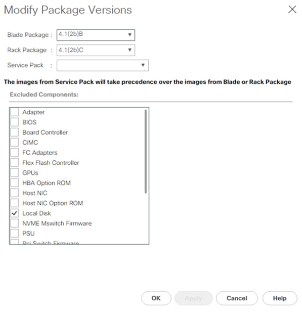
7. Click OK, then click OK again to modify the host firmware package.
Create Local Disk Configuration Policy (Optional)
A local disk configuration specifying no local disks for the Cisco UCS environment can be used to ensure that servers with no local disks are used for SAN Boot.
![]() This policy should not be used on servers that contain local disks.
This policy should not be used on servers that contain local disks.
To create a local disk configuration policy, follow these steps:
1. In Cisco UCS Manager, click Servers.
2. Go to Policies > root.
3. Right-click Local Disk Config Policies.
4. Click Create Local Disk Configuration Policy.
5. Enter SAN-Boot for the local disk configuration policy name.
6. Change the mode to No Local Storage.
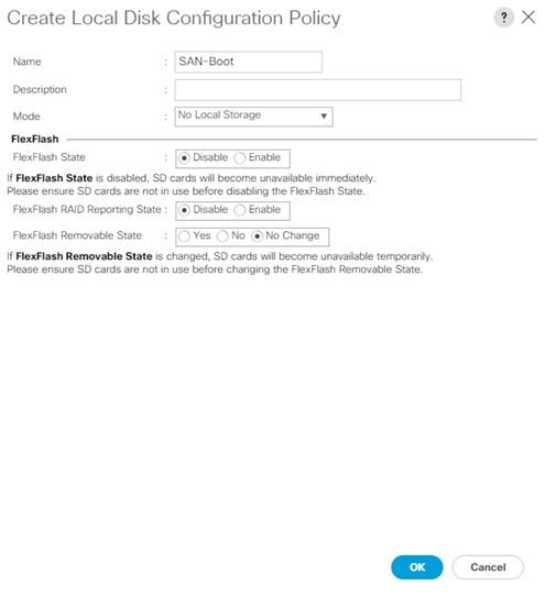
7. Click OK to create the local disk configuration policy.
8. Click OK.
To create a power control policy for the Cisco UCS environment, follow these steps:
1. In Cisco UCS Manager, click Servers.
2. Go to Policies > root.
3. Right-click Power Control Policies.
4. Click Create Power Control Policy.
5. Enter No-Power-Cap for the power control policy name.
6. Change the power capping setting to No Cap.
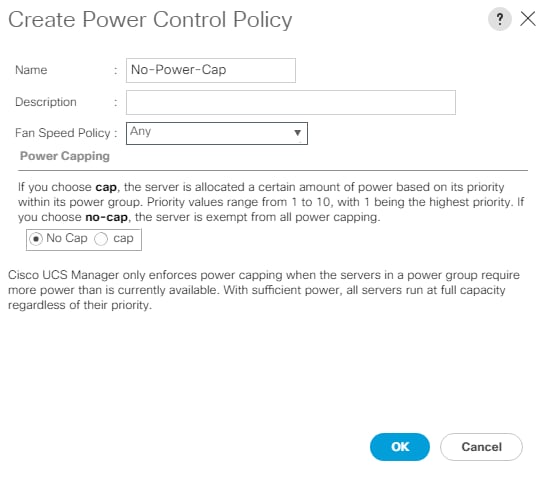
7. Click OK to create the power control policy.
8. Click OK.
Create Server Pool Qualification Policy (Optional)
To create an optional server pool qualification policy for the Cisco UCS environment, follow these steps:
![]() This example creates a policy for Cisco UCS B200 M5 servers for a server pool.
This example creates a policy for Cisco UCS B200 M5 servers for a server pool.
1. In Cisco UCS Manager, click Servers.
2. Expand Policies > root.
3. Right-click Server Pool Policy Qualifications.
4. Click Create Server Pool Policy Qualification.
5. Name the policy UCS-B200M5.
6. Click Create Server PID Qualifications.
7. Click UCSB-B200-M5 from the PID drop-down list.
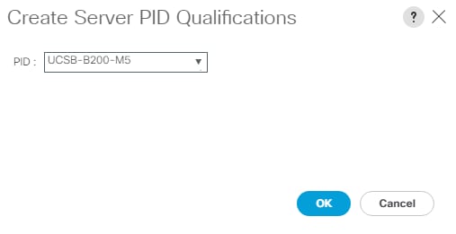
8. Click OK
9. Optionally, choose additional qualifications to refine server selection parameters for the server pool.
10. Click OK to create the policy then click OK to confirm.
Update the Default Maintenance Policy
To update the default Maintenance Policy to either require user acknowledgement before server boot when service profiles change or to make the changes on the next server reboot, follow these steps:
1. In Cisco UCS Manager, click Servers.
2. Go to Policies > root.
3. Click Maintenance Policies > default.
4. Change the Reboot Policy to User Ack.
5. Click “On Next Boot” to delegate maintenance windows to server administrators.
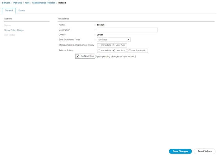
6. Click Save Changes.
7. Click OK to accept the changes.
Create Memory Mode Persistent Memory Policy (Optional)
If any servers in your environment are equipped with Intel Optane DC Persistent Memory (PMEM), a Persistent Memory Policy should be used. Intel Optane DC PMEM can be used in App Direct Mode or Memory Mode with VMware vSphere 7.0. In a Cisco UCS server that is equipped with Intel Optane DC PMEM, if a Persistent Memory Policy is not assigned, 100 percent of the Intel Optane DC PMEM will be used in Memory Mode and the standard DIMMs in the server will be used as cache and the DIMM capacity will not be visible. In VMware vSphere 7.0, usage of Intel Optane DC PMEM in Memory Mode is supported with certain configurations identified in vSphere Support for Intel's Optane Persistent Memory (PMEM) (67645). If you have Intel Optane DC PMEM installed in any of your servers in a configuration identified in the KB, Memory Mode is supported with VMware vSphere 7.0. If you have Intel Optane DC PMEM installed in a server, but not in one of the supported configurations, you should use App Direct Mode.
To create a memory mode persistent memory policy, follow these steps:
1. In Cisco UCS Manager, choose Servers.
2. Go to Policies > root.
3. Right-click Persistent Memory Policy.
4. Click Create Persistent Memory Policy.
5. Name the policy Memory-Mode.
6. Under Goals, click Add.
7. Set Memory Mode (%) to 100 and set Persistent Memory Type to App Direct.
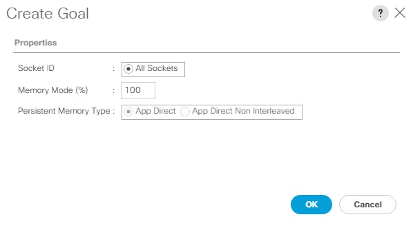
8. Click OK to complete creating the Goal.
9. Click OK to complete creating the policy and click OK on the confirmation.
Create App Direct Mode Persistent Memory Policy (Optional)
If you have Intel Optane DC PMEM installed in a server, but not in one of the supported configurations for Memory Mode, you should use App Direct Mode. You can also use App Direct Mode with any third-party application that supports it.
To create an app direct mode persistent memory policy, follow these steps:
1. In Cisco UCS Manager, click Servers.
2. Go to Policies > root.
3. Right-click Persistent Memory Policy.
4. Click Create Persistent Memory Policy.
5. Name the policy App-Direct-Mode.
6. Under Goals, click Add.
7. Leave Memory Mode (%) set to zero and Persistent Memory Type set to App Direct.
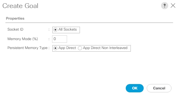
8. Click OK to complete creating the Goal.
9. Click OK to complete creating the policy and click OK to confirm.
In the NetApp ONTAP setup steps, an HTTP web server is required, which is used for hosting ONTAP as well as VMware software. The vMedia Policy created will map the Cisco Custom ISO for UCS 4.1.2a to the Cisco UCS server in order to boot the ESXi installation. To create this policy, follow these steps:
The Cisco Custom ISO for UCS 4.1.2a should also be used for Cisco UCS software release 4.1(2b) and VMware vSphere 7.0.
1. In Cisco UCS Manager, click Servers.
2. Go to Policies > root.
3. Right-click vMedia Policies.
4. Click Create vMedia Policy.
5. Name the policy ESXi-7.0-HTTP.
6. Enter “Mounts Cisco Custom ISO ESXi7 for UCS 4.2(2a)” in the Description field.
7. Click Add to add a vMedia Mount.
8. Name the mount ESXi-7.0-HTTP.
9. Click the CDD Device Type.
10. Click the HTTP Protocol.
11. Enter the IP Address of the web server.
12. To avoid any DNS lookup issues, enter the IP of the web server instead of the hostname.
13. Enter VMware-ESXi-7.0.0-16324942-Custom-Cisco-4.1.2a.iso for the Remote File name.
![]() This VMware ESXi 7.0 Cisco Custom ISO can be downloaded from VMware Downloads.
This VMware ESXi 7.0 Cisco Custom ISO can be downloaded from VMware Downloads.
![]() If a working vCenter 7.0 installation is already in your environment, a FlexPod custom ISO for installing ESXi 7.0 with all necessary drivers for this FlexPod deployment can be created. Please see the Appendix for a procedure for building this custom ISO.
If a working vCenter 7.0 installation is already in your environment, a FlexPod custom ISO for installing ESXi 7.0 with all necessary drivers for this FlexPod deployment can be created. Please see the Appendix for a procedure for building this custom ISO.
14. Enter the web server path to the ISO file in the Remote Path field.
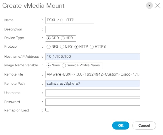
15. Click OK to create the vMedia Mount.
16. Click OK then click OK again to complete creating the vMedia Policy.
For any new servers added to the Cisco UCS environment, the vMedia service profile template can be used to install the ESXi host. On first boot the host will boot into the ESXi installer since the SAN mounted disk is empty. After ESXi is installed, the vMedia will not be referenced as long for the boot disk is accessible.
To create a server BIOS policy for VMware ESXi hosts within the FlexPod organization, follow these steps:
![]() In this lab validation, some Cisco UCS B200 M5 and Cisco UCS C220 M5 servers had TPM2.0 modules installed. To utilize TPM2.0 functionality with VMware vSphere 7.0, the TPM module must be enabled, and Trusted Execution Technology (TXT) disabled in BIOS. According to the Cisco UCS Server BIOS Tokens, Release 4.1 document, these settings are the default or Platform Default settings for all M5 servers. Because of this, these settings do not have to be added to this BIOS policy.
In this lab validation, some Cisco UCS B200 M5 and Cisco UCS C220 M5 servers had TPM2.0 modules installed. To utilize TPM2.0 functionality with VMware vSphere 7.0, the TPM module must be enabled, and Trusted Execution Technology (TXT) disabled in BIOS. According to the Cisco UCS Server BIOS Tokens, Release 4.1 document, these settings are the default or Platform Default settings for all M5 servers. Because of this, these settings do not have to be added to this BIOS policy.
1. In Cisco UCS Manager, click Servers.
2. Go to Policies > root > Sub-Organizations > FlexPod.
3. Right-click BIOS Policies under FlexPod Organization.
4. Click Create BIOS Policy.
5. Enter Intel-VM-Host for the BIOS policy name.
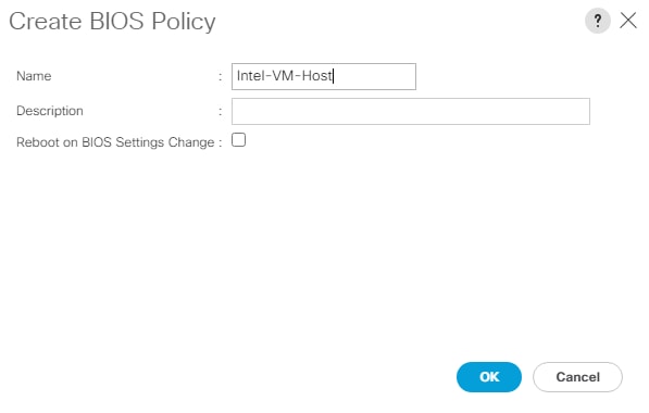
6. Click OK, then click OK again to create the BIOS Policy.
7. Under the FlexPod Organization, expand BIOS Policies and choose the newly created BIOS Policy. Set the following within the Main tab of the Policy:
● CDN Control -> Enabled
● Quiet Boot -> Disabled
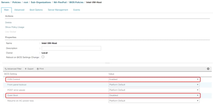
8. Click the Advanced tab, leaving the Processor tab selected within the Advanced tab. Set the following within the Processor tab:
● Processor C State -> Disabled
● Processor C1E -> Disabled
● Processor C3 Report -> Disabled
● Processor C6 Report -> Disabled
● Processor C7 Report -> Disabled
● Power Technology -> Custom
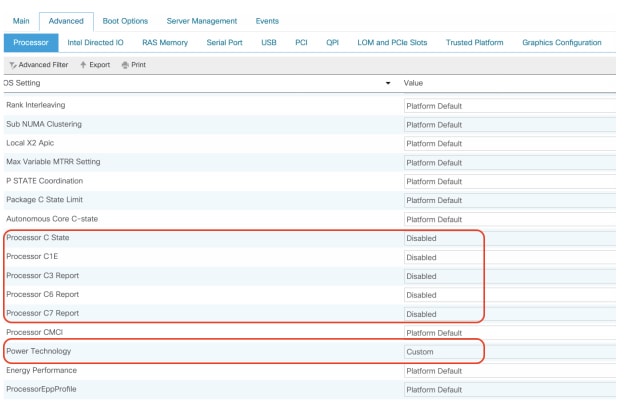
9. Click the RAS Memory tab, and choose:
● NVM Performance Setting -> Balanced Profile
● Memory RAS configuration -> Maximum Performance
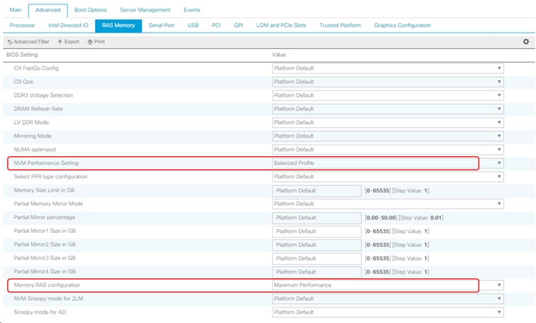
10. Click Save Changes.
11. Click OK.
Create FC Boot Policy (FCP)
This procedure applies to a Cisco UCS environment in which two Fibre Channel logical interfaces (LIFs) are on cluster node 1 (fcp-lif01a and fcp-lif01b) and two Fibre Channel LIFs are on cluster node 2 (fcp-lif02a and fcp-lif02b). Also, it is assumed that the A LIFs are connected to switching Fabric A and the B LIFs are connected to switching Fabric B.
![]() One boot policy is configured in this procedure. The policy configures the primary target to be fcp-lif01a.
One boot policy is configured in this procedure. The policy configures the primary target to be fcp-lif01a.
To create a boot policy for the within the FlexPod organization, follow these steps:
1. In Cisco UCS Manager, click Servers.
2. Go to Policies > root > Sub-Organizations > FlexPod.
3. Under the FlexPod Organization, right-click Boot Policies.
4. Click Create Boot Policy.
5. Enter Boot-FCP-A for the name of the boot policy.
6. Optional: Enter a description for the boot policy.
7. Do not select the Reboot on Boot Order Change checkbox.
8. Click the Uefi Boot Mode.
9. Click the Boot Security checkbox.
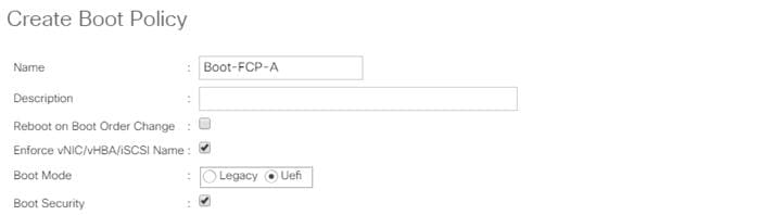
![]() UEFI Secure Boot can be used to boot VMware ESXi 7.0 with or without a TPM 2.0 module in the UCS server.
UEFI Secure Boot can be used to boot VMware ESXi 7.0 with or without a TPM 2.0 module in the UCS server.
10. Expand Local Devices and choose Add Remote CD/DVD.
11. Expand vHBAs and choose Add SAN Boot.
12. Choose Primary for the Type field.
13. Enter FCP-Fabric-A in the vHBA field.
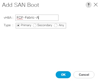
14. Click OK.
15. From vHBAs, choose Add SAN Boot Target.
16. Keep 0 for the value for Boot Target LUN.
17. Enter the WWPN for fcp-lif-01a.
18. To obtain this information, log into the storage cluster and run the network interface show -vserver Infra-SVM command.
19. Choose Primary for the SAN boot target type.
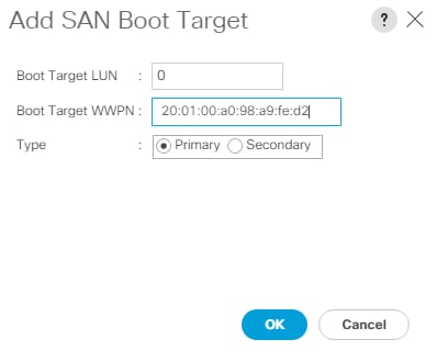
20. Click OK to add the SAN boot target.
21. From vHBAs, choose Add SAN Boot Target.
22. Enter 0 for the value for Boot Target LUN.
23. Enter the WWPN for fcp-lif-02a.
24. Click OK to add the SAN boot target.
25. From vHBAs, choose Add SAN Boot.
26. In the Add SAN Boot dialog box, enter FCP-Fabric-B in the vHBA box.
![]() The SAN boot type should automatically be set to Secondary.
The SAN boot type should automatically be set to Secondary.
27. Click OK.
28. From vHBAs, choose Add SAN Boot Target.
29. Keep 0 for the value for Boot Target LUN.
30. Enter the WWPN for fcp-lif-01b.
31. Choose Primary for the SAN boot target type.
32. Click OK to add the SAN boot target.
33. From vHBAs, choose Add SAN Boot Target.
34. Keep 0 for the value for Boot Target LUN.
35. Enter the WWPN for fcp-lif-02b.
36. Click OK to add the SAN boot target.
37. Expand CIMC Mounted Media and choose Add CIMC Mounted CD/DVD.
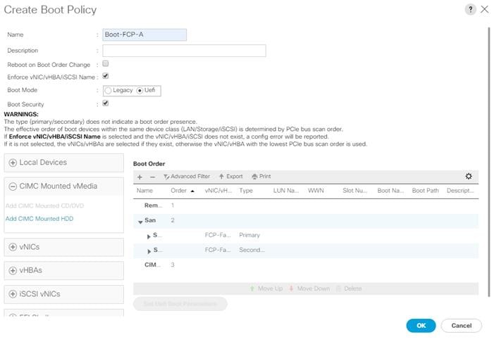
38. Expand San > SAN Primary and select SAN Target Primary. Select Set Uefi Boot Parameters.
![]() For Cisco UCS B200 M5 and Cisco UCS C220 M5 servers, it is not necessary to set the Uefi Boot Parameters. These servers will boot properly with or without these parameters set. However, for M4 and earlier servers, VMware ESXi 7.0 will not boot with Uefi Secure Boot unless these parameters are set exactly as shown.
For Cisco UCS B200 M5 and Cisco UCS C220 M5 servers, it is not necessary to set the Uefi Boot Parameters. These servers will boot properly with or without these parameters set. However, for M4 and earlier servers, VMware ESXi 7.0 will not boot with Uefi Secure Boot unless these parameters are set exactly as shown.
39. Fill in the Set Uefi Boot Parameters exactly as shown in the following screenshot:
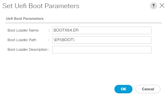
40. Click OK to complete setting the Uefi Boot Parameters for the SAN Boot Target and click OK for the confirmation.
41. Repeat steps 1-40 to set Uefi Boot Parameters for each of the 4 SAN Boot Targets.
42. Click OK, then click OK again to create the boot policy.
Create Service Profile Template (FCP)
In this procedure, one service profile template for Infrastructure ESXi hosts is created for Fabric A boot within the FlexPod organization. To create the service profile template, follow these steps:
1. In Cisco UCS Manager, click Servers.
2. Expand Service Profile Templates > root > Sub-Organizations > FlexPod.
3. Right-click the FlexPod Organization.
4. Choose Create Service Profile Template to open the Create Service Profile Template wizard.
5. Enter Intel-VM-Host-Infra-FCP-A for the name of the service profile template. This service profile template is configured to boot from storage node 1 on fabric A.
6. Choose the Updating Template option.
7. Under UUID, choose UUID_Pool for the UUID pool.
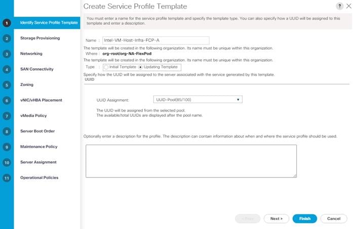
8. Click Next.
Configure Storage Provisioning
To configure storage provisioning, follow these steps:
1. If you have servers with no physical disks, click the Local Disk Configuration Policy tab and choose the SAN-Boot Local Storage Policy. Otherwise, choose the default Local Storage Policy.
2. Click Next.
4. To configure networking, follow these steps:
5. Choose the “Use Connectivity Policy” option to configure the LAN connectivity.
6. Choose FC-Boot from the LAN Connectivity Policy drop-down list.
7. Leave Initiator Name Assignment at <not set>.
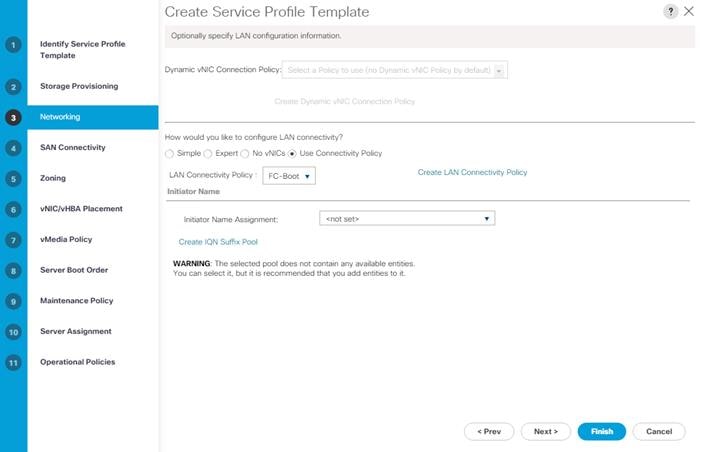
8. Click Next.
To configure SAN connectivity, follow these steps:
1. Choose the Use Connectivity Policy option for the “How would you like to configure SAN connectivity?” field.
2. Choose the FC-Boot option from the SAN Connectivity Policy drop-down list.
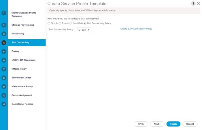
3. Click Next.
To configure zoning, follow this step:
1. Set no zoning options and click Next.
![]() Set no zoning options here since the fabric interconnects are in end host (NPV) mode and zoning is being done in the upstream SAN switch.
Set no zoning options here since the fabric interconnects are in end host (NPV) mode and zoning is being done in the upstream SAN switch.
To configure vNIC/HBA placement, follow these steps:
1. In the Select Placement list, retain the placement policy as Let System Perform Placement.
2. Click Next.
To configure the vMedia policy, follow these steps:
1. Do not select a vMedia Policy.
2. Click Next.
To configure the server boot order, follow these steps:
1. Choose Boot-FCP-A for Boot Policy.
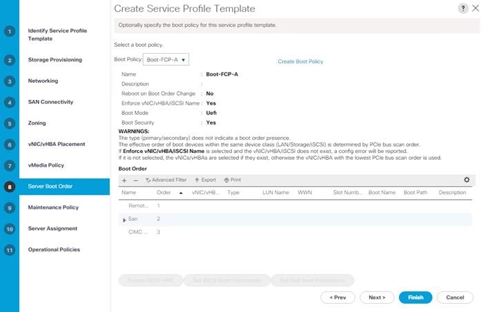
2. Click Next.
To configure the maintenance policy, follow these steps:
1. Change the Maintenance Policy to default.
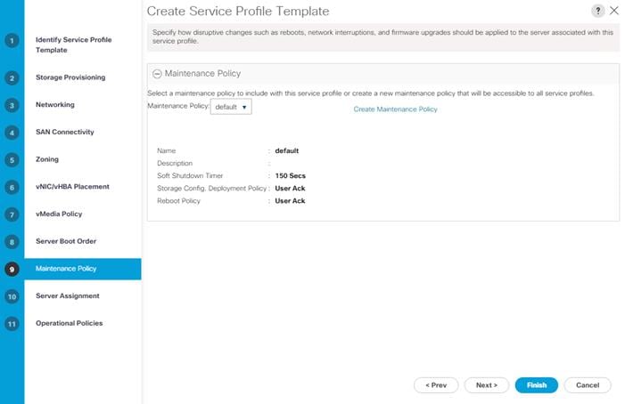
2. Click Next.
To configure server assignment, follow these steps:
1. In the Pool Assignment list, choose Intel-Infra-Pool.
2. Choose Down for the power state to be applied when the profile is associated with the server.
3. Optional: Choose “UCS-B200M5” for the Server Pool Qualification to choose only UCS B200M5 servers in the pool.
4. Expand Firmware Management and choose the default Host Firmware Package.
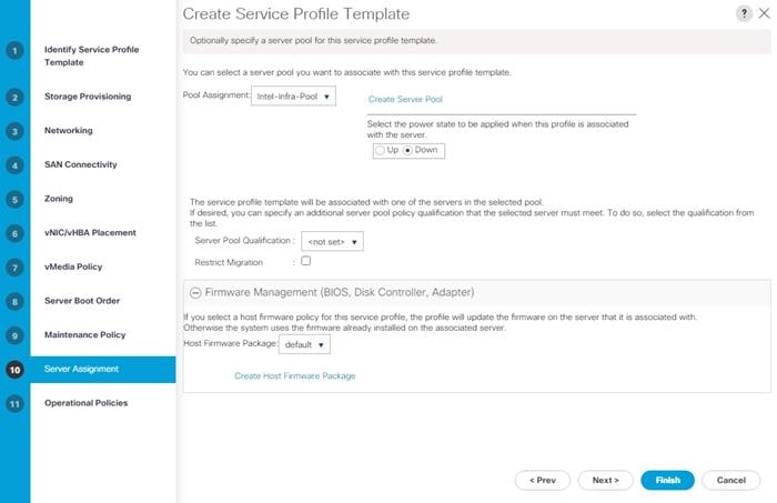
5. Click Next.
Configure Operational Policies
To configure the operational policies, follow these steps:
1. In the BIOS Policy list, choose Intel-VM-Host.
2. Expand Power Control Policy Configuration and choose No-Power-Cap in the Power Control Policy list.
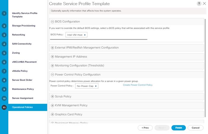
3. Click Finish to create the service profile template.
4. Click OK in the confirmation message.
Create vMedia-Enabled Service Profile Template
To create a service profile template with vMedia enabled, follow these steps:
1. Connect to UCS Manager and click Servers.
2. Go to Service Profile Templates > root > Sub-Organizations > FlexPod > Service Template Intel-VM-Host-Infra-FCP-A.
3. Right-click Intel-VM-Host-Infra-FCP-A and choose Create a Clone.
4. Name the clone Intel-VM-Host-Infra-FCP-A-vM.
5. Click OK then click OK again to create the Service Profile Template clone.
6. Choose the newly created Intel-VM-Host-Infra-FCP-A-vM and choose the vMedia Policy tab.
7. Click Modify vMedia Policy.
8. Choose the ESXi-7.0-HTTP vMedia Policy and click OK.
9. Click OK to confirm.
Create Intel Optane Memory Mode Service Profile Template (Optional)
To create a service profile template for servers with Intel Optane DC PMEM installed and Memory Mode enabled, follow these steps:
1. Connect to UCS Manager and click Servers.
2. Choose Service Profile Templates > root > Sub-Organizations > FlexPod > Service Template Intel-VM-Host-Infra-FCP-A.
3. Right-click Intel-VM-Host-Infra-FCP-A and choose Create a Clone.
4. Name the clone Intel-MM-Host-Infra-FCP-A.
5. Click OK then click OK again to create the Service Profile Template clone.
6. Choose the newly created Intel-MM-Host-Infra-FCP-A and choose the Policies tab.
7. Expand Persistent Memory Policy and use the pulldown to select the Memory-Mode Policy.
8. Click Save Changes.
9. Click OK to confirm.
Create vMedia-Enabled Intel Optane Memory Mode Service Profile Template (Optional)
To create a service profile template with vMedia enabled for servers with Intel Optane DC PMEM installed and Memory Mode enabled, follow these steps:
1. Connect to UCS Manager and click Servers.
2. Go to Service Profile Templates > root > Sub-Organizations > FlexPod > Service Template Intel-MM-Host-Infra-FCP-A.
3. Right-click Intel-MM-Host-Infra-FCP-A and choose Create a Clone.
4. Name the clone Intel-MM-Host-Infra-FCP-A-vM.
5. Click OK then click OK again to create the Service Profile Template clone.
6. Choose the newly created Intel-MM-Host-Infra-FCP-A-vM and choose the vMedia Policy tab.
7. Click Modify vMedia Policy.
8. Choose the ESXi-7.0-HTTP vMedia Policy and click OK.
9. Click OK to confirm.
Create Intel Optane App Direct Mode Service Profile Template (Optional)
To create a service profile template for servers with Intel Optane DC PMEM installed and App Direct Mode enabled, follow these steps:
1. Connect to UCS Manager and click Servers.
2. Choose Service Profile Templates > root > Sub-Organizations > FlexPod > Service Template Intel-VM-Host-Infra-FCP-A.
3. Right-click Intel-VM-Host-Infra-FCP-A and choose Create a Clone.
4. Name the clone Intel-AD-Host-Infra-FCP-A.
5. Click OK then click OK again to create the Service Profile Template clone.
6. Choose the newly created Intel-AD-Host-Infra-FCP-A and choose the Policies tab.
7. Expand Persistent Memory Policy and use the pulldown to select the App-Direct-Mode Policy.
8. Click Save Changes.
9. Click OK to confirm.
Create vMedia-Enabled Intel Optane App Direct Mode Service Profile Template (Optional)
To create a service profile template with vMedia enabled for servers with Intel Optane DC PMEM installed and App Direct Mode enabled, follow these steps:
1. Connect to Cisco UCS Manager and click Servers.
2. Go to Service Profile Templates > root > Sub-Organizations > FlexPod > Service Template Intel-AD-Host-Infra-FCP-A.
3. Right-click Intel-AD-Host-Infra-FCP-A and choose Create a Clone.
4. Name the clone Intel-AD-Host-Infra-FCP-A-vM.
5. Click OK then click OK again to create the Service Profile Template clone.
6. Choose the newly created Intel-AD-Host-Infra-FCP-A-vM and choose the vMedia Policy tab.
7. Click Modify vMedia Policy.
8. Choose the ESXi-7.0-HTTP vMedia Policy and click OK.
9. Click OK to confirm.
To create service profiles from the service profile template within the FlexPod organization, follow these steps:
1. Connect to Cisco UCS Manager and click Servers.
2. Go to Service Profile Templates > root > Sub-Organizations > FlexPod.
3. Right-click the appropriate vMedia-enabled template and choose Create Service Profiles from Template.
4. Enter VM-Host-Infra-0 for the service profile prefix.
5. Enter 1 as “Name Suffix Starting Number.”
6. Enter 3 for the “Number of Instances.”
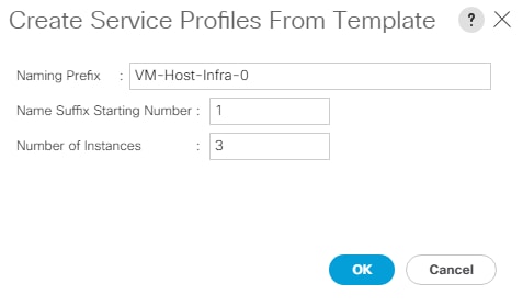
7. Click OK to create the service profiles.
8. Click OK in the confirmation message.
![]() When VMware ESXi 7.0 has been installed on the hosts, the host Service Profiles can be bound to the corresponding non-vMedia-enabled Service Profile Template to remove the vMedia Mapping from the host.
When VMware ESXi 7.0 has been installed on the hosts, the host Service Profiles can be bound to the corresponding non-vMedia-enabled Service Profile Template to remove the vMedia Mapping from the host.
Add More Servers to FlexPod Unit
Additional server pools, service profile templates, and service profiles can be created in the respective organizations to add more servers to the FlexPod unit. All pools and policies created at the organizational level will need to be recreated within other organizations.
After the Cisco UCS service profiles have been created, each infrastructure server in the environment will have a unique configuration. To proceed with the FlexPod deployment, specific information must be gathered from each Cisco UCS server and from the NetApp controllers.
Table 15. WWPNs from NetApp Storage
| SVM |
Adapter |
MDS Switch |
Target: WWPN |
| Infra-SVM |
fcp-lif-01a |
Fabric A |
<fcp-lif-01a-wwpn> |
| fcp-lif-01b |
Fabric B |
<fcp-lif-01b-wwpn> |
|
| fcp-lif-02a |
Fabric A |
<fcp-lif-02a-wwpn> |
|
| fcp-lif-02b |
Fabric B |
<fcp-lif-02b-wwpn> |
To obtain the FC WWPNs, run the network interface show command on the storage cluster management interface.
Table 16. WWPNs for Cisco UCS Service Profiles
| Cisco UCS Service Profile Name |
MDS Switch |
Initiator WWPN |
| VM-Host-Infra-01 |
Fabric A |
<vm-host-infra-01-wwpna> |
| Fabric B |
<vm-host-infra-01-wwpnb> |
|
| Fabric A |
<vm-host-infra-02-wwpna> |
|
| Fabric B |
<vm-host-infra-02-wwpnb> |
|
| VM-Host-Infra-03 |
Fabric A |
<vm-host-infra-03-wwpna> |
| Fabric B |
<vm-host-infra-03-wwpnb> |
To obtain the FC vHBA WWPN information in Cisco UCS Manager GUI, go to Servers > Service Profiles > root > Sub-Organizations > Organization. Expand each service profile and then expand vHBAs. Select each vHBA. The WWPN is shown under Properties on the right.
This section explains how to configure the Cisco MDS 9000s for use in a FlexPod environment.
![]() Follow the steps precisely because failure to do so could result in an improper configuration.
Follow the steps precisely because failure to do so could result in an improper configuration.
![]() If you’re directly connecting storage to the Cisco UCS fabric interconnects, skip this section.
If you’re directly connecting storage to the Cisco UCS fabric interconnects, skip this section.
Physical Connectivity
Follow the physical connectivity guidelines for FlexPod as explained in the section FlexPod Cabling.
FlexPod Cisco MDS Base
The following procedures describe how to configure the Cisco Nexus switches for use in a base FlexPod environment. This procedure assumes you are using the Cisco MDS 9132T with NX-OS 8.4(1a).
Cisco MDS 9132T A
To set up the initial configuration for the Cisco MDS A switch, <mds-A-hostname>, follow these steps:
1. On initial boot and connection to the serial or console port of the switch, the NX-OS setup should automatically start and attempt to enter Power on Auto Provisioning. Enter y to get to the System Admin Account Setup.
2. Configure the switch using the command line:
---- System Admin Account Setup ----
Do you want to enforce secure password standard (yes/no) [y]: Enter
Enter the password for "admin": <password>
Confirm the password for "admin": <password>
Would you like to enter the basic configuration dialog (yes/no): yes
Create another login account (yes/no) [n]: Enter
Configure read-only SNMP community string (yes/no) [n]: Enter
Configure read-write SNMP community string (yes/no) [n]: Enter
Enter the switch name : <mds-A-hostname>
Continue with Out-of-band (mgmt0) management configuration? (yes/no) [y]: Enter
Mgmt0 IPv4 address : <mds-A-mgmt0-ip>
Mgmt0 IPv4 netmask : <mds-A-mgmt0-netmask>
Configure the default gateway? (yes/no) [y]: Enter
IPv4 address of the default gateway : <mds-A-mgmt0-gw>
Configure advanced IP options? (yes/no) [n]: Enter
Enable the ssh service? (yes/no) [y]: Enter
Type of ssh key you would like to generate (dsa/rsa) [rsa]: Enter
Number of rsa key bits <1024-2048> [1024]: Enter
Enable the telnet service? (yes/no) [n]: Enter
Configure congestion/no_credit drop for fc interfaces? (yes/no) [y]: Enter
Enter the type of drop to configure congestion/no_credit drop? (con/no) [c]: Enter
Enter milliseconds in multiples of 10 for congestion-drop for logical-type edge
in range (<200-500>/default), where default is 500. [d]: Enter
Enable the http-server? (yes/no) [y]: Enter
Configure clock? (yes/no) [n]: Enter
Configure timezone? (yes/no) [n]: Enter
Configure summertime? (yes/no) [n]: Enter
Configure the ntp server? (yes/no) [n]: yes
NTP server IPv4 address : <nexus-A-mgmt0-ip>
Configure default switchport interface state (shut/noshut) [shut]: Enter
Configure default switchport trunk mode (on/off/auto) [on]: auto
Configure default switchport port mode F (yes/no) [n]: yes
Configure default zone policy (permit/deny) [deny]: Enter
Enable full zoneset distribution? (yes/no) [n]: Enter
Configure default zone mode (basic/enhanced) [basic]: Enter
3. Review the configuration:
Would you like to edit the configuration? (yes/no) [n]: Enter
Use this configuration and save it? (yes/no) [y]: Enter
Cisco MDS 9132T B
To set up the initial configuration for the Cisco MDS B switch, <mds-B-hostname>, follow these steps:
1. On initial boot and connection to the serial or console port of the switch, the NX-OS setup should automatically start and attempt to enter Power on Auto Provisioning. Enter y to get to the System Admin Account Setup.
2. Configure the switch using the command line:
---- System Admin Account Setup ----
Do you want to enforce secure password standard (yes/no) [y]: Enter
Enter the password for "admin": <password>
Confirm the password for "admin": <password>
Would you like to enter the basic configuration dialog (yes/no): yes
Create another login account (yes/no) [n]: Enter
Configure read-only SNMP community string (yes/no) [n]: Enter
Configure read-write SNMP community string (yes/no) [n]: Enter
Enter the switch name : <mds-B-hostname>
Continue with Out-of-band (mgmt0) management configuration? (yes/no) [y]: Enter
Mgmt0 IPv4 address : <mds-B-mgmt0-ip>
Mgmt0 IPv4 netmask : <mds-B-mgmt0-netmask>
Configure the default gateway? (yes/no) [y]: Enter
IPv4 address of the default gateway : <mds-B-mgmt0-gw>
Configure advanced IP options? (yes/no) [n]: Enter
Enable the ssh service? (yes/no) [y]: Enter
Type of ssh key you would like to generate (dsa/rsa) [rsa]: Enter
Number of rsa key bits <1024-2048> [1024]: Enter
Enable the telnet service? (yes/no) [n]: Enter
Configure congestion/no_credit drop for fc interfaces? (yes/no) [y]: Enter
Enter the type of drop to configure congestion/no_credit drop? (con/no) [c]: Enter
Enter milliseconds in multiples of 10 for congestion-drop for logical-type edge
in range (<200-500>/default), where default is 500. [d]: Enter
Enable the http-server? (yes/no) [y]: Enter
Configure clock? (yes/no) [n]: Enter
Configure timezone? (yes/no) [n]: Enter
Configure summertime? (yes/no) [n]: Enter
Configure the ntp server? (yes/no) [n]: yes
NTP server IPv4 address : <nexus-A-mgmt0-ip>
Configure default switchport interface state (shut/noshut) [shut]: Enter
Configure default switchport trunk mode (on/off/auto) [on]: auto
Configure default switchport port mode F (yes/no) [n]: yes
Configure default zone policy (permit/deny) [deny]: Enter
Enable full zoneset distribution? (yes/no) [n]: Enter
Configure default zone mode (basic/enhanced) [basic]: Enter
3. Review the configuration:
Would you like to edit the configuration? (yes/no) [n]: Enter
Use this configuration and save it? (yes/no) [y]: Enter
FlexPod Cisco MDS Switch Configuration
Cisco MDS 9132T A and Cisco MDS 9132T B
To enable the correct features on the Cisco MDS switches, follow these steps:
1. Log in as admin.
2. Run the following commands:
configure terminal
feature npiv
feature fport-channel-trunk
3. Add Second NTP Server and Local Time Configuration
Cisco MDS 9132T A and Cisco MDS 9132T B
To configure the second NTP server and add local time configuration, follow this step:
1. From the global configuration mode, run the following command:
ntp server <nexus-B-mgmt0-ip>
clock timezone <timezone> <hour-offset> <minute-offset>
clock summer-time <timezone> <start-week> <start-day> <start-month> <start-time> <end-week> <end-day> <end-month> <end-time> <offset-minutes>
![]() It is important to configure the local time so that logging time alignment, any backup schedules, and SAN Analytics forwarding are correct. For more information on configuring the timezone and daylight savings time or summer time, please see the Cisco MDS 9000 Series Fundamentals Configuration Guide, Release 8.x.
It is important to configure the local time so that logging time alignment, any backup schedules, and SAN Analytics forwarding are correct. For more information on configuring the timezone and daylight savings time or summer time, please see the Cisco MDS 9000 Series Fundamentals Configuration Guide, Release 8.x.
Sample clock commands for the United States Eastern timezone are:
clock timezone EST -5 0
clock summer-time EDT 2 Sunday March 02:00 1 Sunday November 02:00 60
Cisco MDS 9132T A
To configure individual ports and port-channels for switch A, follow this step:
1. From the global configuration mode, run the following commands:
switchport description <st-clustername>-1:2a
switchport speed 32000
switchport trunk mode off
no shutdown
exit
interface fc1/10
switchport description <st-clustername>-2:2a
switchport speed 32000
switchport trunk mode off
no shutdown
exit
interface fc1/5
switchport description <ucs-clustername>-a:1/1
channel-group 15
no shutdown
exit
interface fc1/6
switchport description <ucs-clustername>-a:1/2
channel-group 15
no shutdown
exit
interface port-channel15
channel mode active
switchport trunk allowed vsan <vsan-a-id>
switchport description <ucs-clustername>-a
switchport speed 32000
no shutdown
exit
Cisco MDS 9132T B
To configure individual ports and port-channels for switch B, follow this step:
1. From the global configuration mode, run the following commands:
interface fc1/9
switchport description <st-clustername>-1:2b
switchport speed 32000
switchport trunk mode off
no shutdown
exit
interface fc1/10
switchport description <st-clustername>-2:2b
switchport speed 32000
switchport trunk mode off
no shutdown
exit
interface fc1/5
switchport description <ucs-clustername>-b:1/1
channel-group 15
no shutdown
exit
interface fc1/6
switchport description <ucs-clustername>-b:1/2
channel-group 15
no shutdown
exit
interface port-channel15
channel mode active
switchport trunk allowed vsan <vsan-b-id>
switchport description <ucs-clustername>-b
switchport speed 32000
no shutdown
exit
![]() If VSAN trunking is not being used between the Cisco UCS Fabric Interconnects and the MDS switches, do not enter “switchport trunk allowed vsan <vsan-b-id>” for interface port-channel15. The default setting of switchport trunk mode auto is being used for the port channel.
If VSAN trunking is not being used between the Cisco UCS Fabric Interconnects and the MDS switches, do not enter “switchport trunk allowed vsan <vsan-b-id>” for interface port-channel15. The default setting of switchport trunk mode auto is being used for the port channel.
Cisco MDS 9132T A
To create the necessary VSANs for fabric A and add ports to them, follow these steps:
1. From the global configuration mode, run the following commands:
vsan database
vsan <vsan-a-id>
vsan <vsan-a-id> name Fabric-A
exit
zone smart-zoning enable vsan <vsan-a-id>
vsan database
vsan <vsan-a-id> interface fc1/9
vsan <vsan-a-id> interface fc1/10
vsan <vsan-a-id> interface port-channel15
exit
Cisco MDS 9132T B
To create the necessary VSANs for fabric B and add ports to them, follow these steps:
1. From the global configuration mode, run the following commands:
vsan database
vsan <vsan-b-id>
vsan <vsan-b-id> name Fabric-B
exit
zone smart-zoning enable vsan <vsan-b-id>
vsan database
vsan <vsan-b-id> interface fc1/9
vsan <vsan-b-id> interface fc1/10
vsan <vsan-b-id> interface port-channel15
exit
2. At this point, it may be necessary to go into Cisco UCS Manager and disable and then enable the FC port-channel interfaces to get the port-channels to come up.
Cisco MDS 9132T A
To create device aliases for Fabric A that will be used to create zones, follow this step:
1. From the global configuration mode, run the following commands:
device-alias mode enhanced
device-alias database
device-alias name Infra-SVM-fcp-lif-01a pwwn <fcp-lif-01a-wwpn>
device-alias name Infra-SVM-fcp-lif-02a pwwn <fcp-lif-02a-wwpn>
device-alias name VM-Host-Infra-01-A pwwn <vm-host-infra-01-wwpna>
device-alias name VM-Host-Infra-02-A pwwn <vm-host-infra-02-wwpna>
device-alias name VM-Host-Infra-03-A pwwn <vm-host-infra-03-wwpna>
device-alias commit
Cisco MDS 9132T B
To create device aliases for Fabric B that will be used to create zones, follow this step:
1. From the global configuration mode, run the following commands:
device-alias mode enhanced
device-alias database
device-alias name Infra-SVM-fcp-lif-01b pwwn <fcp-lif-01b-wwpn>
device-alias name Infra-SVM-fcp-lif-02b pwwn <fcp-lif-02b-wwpn>
device-alias name VM-Host-Infra-01-B pwwn <vm-host-infra-01-wwpnb>
device-alias name VM-Host-Infra-02-B pwwn <vm-host-infra-02-wwpnb>
device-alias name VM-Host-Infra-03-B pwwn <vm-host-infra-03-wwpnb>
device-alias commit
Cisco MDS 9132T A
To create the required zones and zoneset on Fabric A, run the following commands:
configure terminal
zone name Infra-SVM-Fabric-A vsan <vsan-a-id>
member device-alias VM-Host-Infra-01-A init
member device-alias VM-Host-Infra-02-A init
member device-alias VM-Host-Infra-03-A init
member device-alias Infra-SVM-fcp-lif-01a target
member device-alias Infra-SVM-fcp-lif-02a target
exit
zoneset name Fabric-A vsan <vsan-a-id>
member Infra-SVM-Fabric-A
exit
zoneset activate name Fabric-A vsan <vsan-a-id>
show zoneset active
copy r s
Since Smart Zoning is enabled, a single zone is created with all host boot initiators and boot targets for the Infra-SVM instead of creating a separate zone for each host with the host initiator and boot targets. If a new host is added, its boot initiator can simply be added to the single zone in each MDS switch and then the zoneset reactivated. If another SVM is added to the FlexPod with FC targets, a new zone can be added for that SVM.
Cisco MDS 9132T B
To create the required zones and zoneset on Fabric B, run the following commands:
configure terminal
zone name Infra-SVM-Fabric-B vsan <vsan-b-id>
member device-alias VM-Host-Infra-01-B init
member device-alias VM-Host-Infra-02-B init
member device-alias VM-Host-Infra-03-B init
member device-alias Infra-SVM-fcp-lif-01b target
member device-alias Infra-SVM-fcp-lif-02b target
exit
zoneset name Fabric-B vsan <vsan-b-id>
member Infra-SVM-Fabric-B
exit
zoneset activate name Fabric-B vsan <vsan-b-id>
exit
show zoneset active
copy r s
Storage Configuration – Boot LUNs
To create igroups, follow these steps:
1. Create initiator groups (igroups) by entering the following commands from the storage cluster management node Secure Shell (SSH) connection:
lun igroup create –vserver Infra-SVM –igroup VM-Host-Infra-01 –protocol fcp –ostype vmware –initiator <vm-host-infra-01-wwpna>, <vm-host-infra-01-wwpnb>
lun igroup create –vserver Infra-SVM –igroup VM-Host-Infra-02 –protocol fcp –ostype vmware –initiator <vm-host-infra-02-wwpna>, <vm-host-infra-02-wwpnb>
lun igroup create –vserver Infra-SVM –igroup VM-Host-Infra-03 –protocol fcp –ostype vmware –initiator <vm-host-infra-03-wwpna>, <vm-host-infra-03-wwpnb>
lun igroup create –vserver Infra-SVM –igroup MGMT-Hosts –protocol fcp –ostype vmware –initiator <vm-host-infra-01-wwpna>, <vm-host-infra-01-wwpnb>, <vm-host-infra-02-wwpna>, <vm-host-infra-02-wwpnb>, <vm-host-infra-03-wwpna>, <vm-host-infra-03-wwpnb>
2. Use the values listed in Table 6 and Table 7 for the WWPN information.
3. To view the three igroups just created, use the command lun igroup show.
lun igroup show -protocol fcp
To map boot LUNs to igroups, follow this step:
1. From the storage cluster management SSH connection, enter the following commands:
lun mapping create –vserver Infra-SVM –path /vol/esxi_boot/VM-Host-Infra-01 –igroup VM-Host-Infra-01 –lun-id 0
lun mapping create –vserver Infra-SVM –path /vol/esxi_boot/VM-Host-Infra-02 –igroup VM-Host-Infra-02 –lun-id 0
lun mapping create –vserver Infra-SVM –path /vol/esxi_boot/VM-Host-Infra-03 –igroup VM-Host-Infra-03 –lun-id 0
This section provides detailed instructions for installing VMware ESXi 7.0 in a FlexPod environment. After the procedures are completed, three booted ESXi hosts will be provisioned.
Several methods exist for installing ESXi in a VMware environment. These procedures focus on how to use the built-in keyboard, video, mouse (KVM) console and virtual media features in Cisco UCS Manager to map remote installation media to individual servers and connect to their boot logical unit numbers (LUNs).
If the VMware ESXi ISO has not already been downloaded, follow these steps:
1. Click the following link: Cisco Custom ISO for UCS 4.1.2a. You will need a user id and password on vmware.com to download this software.
![]() The Cisco Custom ISO for UCS 4.1.2a should also be used for Cisco UCS software release 4.1(2b) and VMware vSphere 7.0.
The Cisco Custom ISO for UCS 4.1.2a should also be used for Cisco UCS software release 4.1(2b) and VMware vSphere 7.0.
2. Download the .iso file.
Log into Cisco UCS 6454 Fabric Interconnect
Cisco UCS Manager
The Cisco UCS IP KVM enables the administrator to begin the installation of the operating system (OS) through remote media. It is necessary to log in to the Cisco UCS environment to run the IP KVM.
To log into the Cisco UCS environment, follow these steps:
1. Open a web browser and enter the IP address for the Cisco UCS cluster address. This step launches the Cisco UCS Manager application.
2. Click the Launch UCS Manager link to launch the HTML 5 UCS Manager GUI.
3. If prompted to accept security certificates, accept as necessary.
4. When prompted, enter admin for the user name and enter the administrative password.
5. To log in to Cisco UCS Manager, click Login.
6. From the main menu, click Servers.
8. In the Actions pane, click KVM Console.
9. Follow the prompts to launch the HTML5 KVM console.
10. Choose Servers > Service Profiles > root > Sub-Organizations > FlexPod Organization > VM-Host-Infra-02.
11. In the Actions pane, click KVM Console.
12. Follow the prompts to launch the HTML5 KVM console.
13. Go to Servers > Service Profiles > root > Sub-Organizations > FlexPod Organization > VM-Host-Infra-03.
14. In the Actions pane, click KVM Console.
15. Follow the prompts to launch the HTML5 KVM console.
Set Up VMware ESXi Installation
ESXi Hosts VM-Host-Infra-01, VM-Host-Infra-02, and VM-Host-Infra-03
![]() Skip this section if you’re using vMedia policies; the ISO file will already be connected to KVM.
Skip this section if you’re using vMedia policies; the ISO file will already be connected to KVM.
To prepare the server for the OS installation, follow these steps on each ESXi host:
1. In the KVM window, click Virtual Media.
2. Choose Activate Virtual Devices.
3. If prompted to accept an Unencrypted KVM session, accept as necessary.
4. Click Virtual Media and choose Map CD/DVD.
5. Browse to the ESXi installer ISO image file and click Open.
6. Click Map Device.
7. Click the KVM Console tab to monitor the server boot.
ESXi Hosts VM-Host-Infra-01, VM-Host-Infra-02, and VM-Host-Infra-03
To install VMware ESXi to the bootable LUN of the hosts, follow these steps on each host:
1. Boot the server by selecting Boot Server in the KVM and click OK, then click OK again.
2. On boot, the machine detects the presence of the ESXi installation media and loads the ESXi installer.
![]() If the ESXi installer fails to load because the software certificates cannot be validated, reset the server, and when prompted, press F2 to go into BIOS and set the system time and date to current. Now the ESXi installer should load properly.
If the ESXi installer fails to load because the software certificates cannot be validated, reset the server, and when prompted, press F2 to go into BIOS and set the system time and date to current. Now the ESXi installer should load properly.
3. After the installer is finished loading, press Enter to continue with the installation.
4. Read and accept the end-user license agreement (EULA). Press F11 to accept and continue.
![]() It may be necessary to map function keys as User Defined Macros under the Macros menu in the Cisco UCS KVM console.
It may be necessary to map function keys as User Defined Macros under the Macros menu in the Cisco UCS KVM console.
5. Choose the LUN that was previously set up for the installation disk for ESXi and press Enter to continue with the installation.
6. Choose the appropriate keyboard layout and press Enter.
7. Enter and confirm the root password and press Enter.
8. The installer issues a warning that the selected disk will be repartitioned. Press F11 to continue with the installation.
9. After the installation is complete, press Enter to reboot the server.
![]() The ESXi installation image will be automatically unmapped in the KVM when Enter is pressed.
The ESXi installation image will be automatically unmapped in the KVM when Enter is pressed.
10. In Cisco UCS Manager, bind the current service profile to the non-vMedia service profile template to prevent mounting the ESXi installation iso over HTTP.
Set Up Management Networking for ESXi Hosts
Adding a management network for each VMware host is necessary for managing the host. To add a management network for the VMware hosts, follow these steps on each ESXi host:
ESXi Host VM-Host-Infra-01, VM-Host-Infra-02, and VM-Host-Infra-03
To configure each ESXi host with access to the management network, follow these steps:
1. After the server has finished rebooting, in the UCS KVM console, press F2 to customize VMware ESXi.
2. Log in as root, enter the corresponding password, and press Enter to log in.
3. Use the down arrow key to choose Troubleshooting Options and press Enter.
4. Choose Enable ESXi Shell and press Enter.
5. Choose Enable SSH and press Enter.
6. Press Esc to exit the Troubleshooting Options menu.
7. Choose the Configure Management Network option and press Enter.
8. Choose Network Adapters and press Enter.
9. Verify that the numbers in the Hardware Label field match the numbers in the Device Name field. If the numbers do not match, note the mapping of vmnic ports to vNIC ports for later use.
10. Using the spacebar, choose vmnic1.
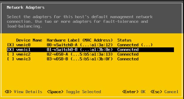
![]() In lab testing, examples were seen where the vmnic and device ordering do not match. In this case, use the Consistent Device Naming (CDN) to note which vmnics are mapped to which vNICs and adjust the upcoming procedure accordingly.
In lab testing, examples were seen where the vmnic and device ordering do not match. In this case, use the Consistent Device Naming (CDN) to note which vmnics are mapped to which vNICs and adjust the upcoming procedure accordingly.
11. Press Enter.
12. Choose the VLAN (Optional) option and press Enter.
13. Enter the <ib-mgmt-vlan-id> and press Enter.
14. Choose IPv4 Configuration and press Enter.
15. Choose the “Set static IPv4 address and network configuration” option by using the arrow keys and space bar.
16. Move to the IPv4 Address field and enter the IP address for managing the ESXi host.
17. Move to the Subnet Mask field and enter the subnet mask for the ESXi host.
18. Move to the Default Gateway field and enter the default gateway for the ESXi host.
19. Press Enter to accept the changes to the IP configuration.
20. Choose the IPv6 Configuration option and press Enter.
21. Using the spacebar, choose Disable IPv6 (restart required) and press Enter.
22. Choose the DNS Configuration option and press Enter.
![]() Since the IP address is assigned manually, the DNS information must also be entered manually.
Since the IP address is assigned manually, the DNS information must also be entered manually.
23. Using the spacebar, choose “Use the following DNS server addresses and hostname:”
24. Move to the Primary DNS Server field and enter the IP address of the primary DNS server.
25. Optional: Move to the Alternate DNS Server field and enter the IP address of the secondary DNS server.
26. Move to the Hostname field and enter the fully qualified domain name (FQDN) for the ESXi host.
27. Press Enter to accept the changes to the DNS configuration.
28. Press Esc to exit the Configure Management Network submenu.
29. Press Y to confirm the changes and reboot the ESXi host.
Reset VMware ESXi Host VMkernel Port vmk0 MAC Address (Optional)
ESXi Host VM-Host-Infra-01, VM-Host-Infra-02, and VM-Host-Infra-03
By default, the MAC address of the management VMkernel port vmk0 is the same for the MAC address of the Ethernet port it is placed on. If the ESXi host’s boot LUN is remapped to a different server with different MAC addresses, a MAC address conflict will exist because vmk0 will retain the assigned MAC address unless the ESXi System Configuration is reset. To reset the MAC address of vmk0 to a random VMware-assigned MAC address, follow these steps:
1. From the ESXi console menu main screen, type Ctrl-Alt-F1 to access the VMware console command line interface. In the UCSM KVM, Ctrl-Alt-F1 appears in the list of Static Macros.
2. Log in as root.
3. Type esxcfg-vmknic –l to get a detailed listing of interface vmk0. vmk0 should be a part of the “Management Network” port group. Note the IP address and netmask of vmk0.
4. To remove vmk0, type esxcfg-vmknic –d “Management Network”.
5. To re-add vmk0 with a random MAC address, type esxcfg-vmknic –a –i <vmk0-ip> -n <vmk0-netmask> “Management Network.”
6. Verify vmk0 has been re-added with a random MAC address by typing esxcfg-vmknic –l.
7. Tag vmk0 for the management interface by typing esxcli network ip interface tag add -i vmk0 -t Management.
8. When vmk0 was re-added, if a message popped up saying vmk1 was marked for the management interface, type esxcli network ip interface tag remove -i vmk1 -t Management.
9. If this VMware ESXi host is iSCSI booted, the vmk1, iScsiBootPG-A interface’s MAC address can also be reset to a random, VMware-assigned MAC address.
a. Type esxcfg-vmknic –l to get a detailed listing of interface vmk1. vmk1 should be a part of the “iScsiBootPG-A” port group and should have a MAC address from the UCS MAC Pool. Note the IP address and netmask of vmk1.
b. To remove vmk1, type esxcfg-vmknic –d “iScsiBootPG-A”.
c. To re-add vmk1 with a random MAC address, type esxcfg-vmknic –a –i <vmk1-ip> -n <vmk1-netmask> -m 9000 “iScsiBootPG-A”.
d. Verify vmk1 has been re-added with a random MAC address by typing esxcfg-vmknic –l.
10. Type exit to log out of the command line interface.
11. Type Ctrl-Alt-F2 to return to the ESXi console menu interface.
Install VMware and Cisco VIC Drivers for the ESXi Host
Download the offline bundle for the Cisco UCS Tools Component and the NetApp NFS Plug-in for VMware VAAI to the Management workstation:
Cisco UCS Tools Component for ESXi 7.0 1.1.5 (ucs-tool-esxi_1.1.5-1OEM.zip)
NetApp NFS Plug-in 1.1.2-3 for VMware VAAI (ucs-tool-esxi_1.1.2-1OEM.zip)
![]() This document describes using the driver versions shown above along with Cisco VIC nenic version 1.0.33.0 and nfnic version 4.0.0.56 along with VMware vSphere version 7.0.0, Cisco UCS version 4.1(2a), and the latest patch NetApp ONTAP 9.7. These were the versions validated and supported at the time this document was published. This document can be used as a guide for configuring future versions of software. Consult the Cisco UCS Hardware Compatibility List and the NetApp Interoperability Matrix Tool to determine supported combinations of firmware and software.
This document describes using the driver versions shown above along with Cisco VIC nenic version 1.0.33.0 and nfnic version 4.0.0.56 along with VMware vSphere version 7.0.0, Cisco UCS version 4.1(2a), and the latest patch NetApp ONTAP 9.7. These were the versions validated and supported at the time this document was published. This document can be used as a guide for configuring future versions of software. Consult the Cisco UCS Hardware Compatibility List and the NetApp Interoperability Matrix Tool to determine supported combinations of firmware and software.
ESXi Hosts VM-Host-Infra-01, VM-Host-Infra-02, and VM-Host-Infra-03
To install VMware VIC Drivers and the NetApp NFS Plug-in for VMware VAAI on the ESXi host VM-Host-Infra-01 and VM-Host-Infra-02, follow these steps:
1. Using an SCP program such as WinSCP, copy the two offline bundles referenced above to the /tmp directory on each ESXi host.
2. Using a ssh tool such as PuTTY, ssh to each VMware ESXi host. Log in as root with the root password.
3. Type cd /tmp.
4. Run the following commands on each host:
esxcli software component apply -d /tmp/ucs-tool-esxi_1.1.5-1OEM.zip
esxcli software vib install -d /tmp/NetAppNasPlugin.v23.zip
reboot
5. After reboot, log back into each host and run the following commands and ensure the correct version is installed:
esxcli software component list | grep ucs
esxcli software vib list | grep NetApp
Log into the First VMware ESXi Host by Using VMware Host Client
ESXi Host VM-Host-Infra-01
To log into the VM-Host-Infra-01 ESXi host by using the VMware Host Client, follow these steps:
1. Open a web browser on the management workstation and navigate to the VM-Host-Infra-01 management IP address.
2. Enter root for the User name.
3. Enter the root password.
4. Click Login to connect.
5. Decide whether to join the VMware Customer Experience Improvement Program and click OK.
Set Up VMkernel Ports and Virtual Switch
ESXi Host VM-Host-Infra-01
To set up the VMkernel ports and the virtual switches on the first ESXi host, follow these steps:
![]() In this procedure, you’re only setting up the first ESXi host. The second and third hosts will be added to vCenter and setup from the vCenter HTML5 Interface.
In this procedure, you’re only setting up the first ESXi host. The second and third hosts will be added to vCenter and setup from the vCenter HTML5 Interface.
1. From the Host Client Navigator, choose Networking.
2. In the center pane, choose the Virtual switches tab.
3. Highlight the vSwitch0 line.
4. Choose Edit settings.
5. Change the MTU to 9000.
6. Expand NIC teaming.
7. In the Failover order section, choose vmnic1 and click Mark active.
8. Verify that vmnic1 now has a status of Active.
9. Click Save.
10. Choose Networking, then choose the Port groups tab.
11. In the center pane, right-click VM Network and choose Edit settings.
12. Name the port group IB-MGMT Network and enter <ib-mgmt-vlan-id> in the VLAN ID field.
13. Click Save to finalize the edits for the IB-MGMT Network.
14. At the top, choose the VMkernel NICs tab.
15. Click Add VMkernel NIC.
16. For New port group, enter VMkernel-Infra-NFS.
17. For Virtual switch, choose vSwitch0.
18. Enter <infra-nfs-vlan-id> for the VLAN ID.
19. Change the MTU to 9000.
20. Choose Static IPv4 settings and expand IPv4 settings.
21. Enter the ESXi host Infrastructure NFS IP address and netmask.
22. Leave TCP/IP stack set at Default TCP/IP stack and do not choose any of the Services.
23. Click Create.
24. Click Add VMkernel NIC.
25. For New port group, enter VMkernel-vMotion.
26. For Virtual switch, choose vSwitch0.
27. Enter <vmotion-vlan-id> for the VLAN ID.
29. Choose Static IPv4 settings and expand IPv4 settings.
30. Enter the ESXi host vMotion IP address and netmask.
31. Choose the vMotion stack for TCP/IP stack.
32. Click Create.
33. Optionally, create two more vMotion VMkernel NICs to increase the speed of multiple simultaneous vMotion on this solution’s 40 and 50GE vNICs:
b. For New port group, enter VMkernel-vMotion1.
c. For Virtual switch, choose vSwitch0.
d. Enter <vmotion-vlan-id> for the VLAN ID.
e. Change the MTU to 9000.
f. Choose Static IPv4 settings and expand IPv4 settings.
g. Enter the ESXi host’s second vMotion IP address and netmask.
h. Choose the vMotion stack for TCP/IP stack.
i. Click Create.
j. Click Add VMkernel NIC.
k. For New port group, enter VMkernel-vMotion2.
l. For Virtual switch, choose vSwitch0.
m. Enter <vmotion-vlan-id> for the VLAN ID.
n. Change the MTU to 9000.
o. Choose Static IPv4 settings and expand IPv4 settings.
p. Enter the ESXi host’s third vMotion IP address and netmask.
q. Choose the vMotion stack for TCP/IP stack.
r. Click Create.
34. Choose the Virtual Switches tab, then vSwitch0. The properties for vSwitch0 VMkernel NICs should be similar to the following example:
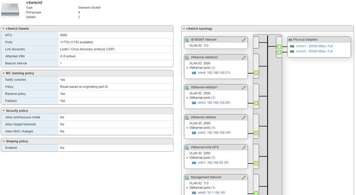
35. Choose Networking and the VMkernel NICs tab to confirm configured virtual adapters. The adapters listed should be similar to the following example:
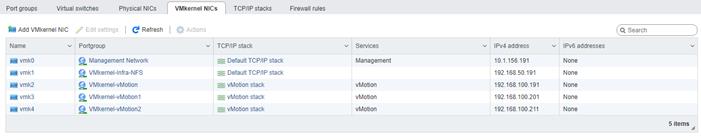
ESXi Host VM-Host-Infra-01
To mount the required datastores, follow these steps on the first ESXi host:
1. From the Host Client, choose Storage.
2. In the center pane, choose the Datastores tab.
3. In the center pane, choose New Datastore to add a new datastore.
4. In the New datastore popup, choose Mount NFS datastore and click Next.
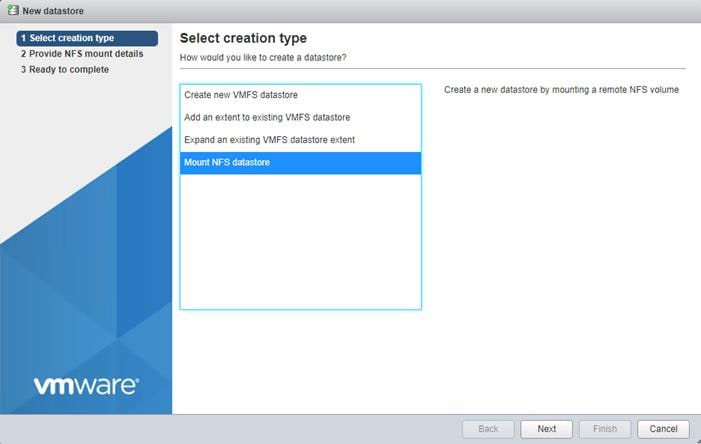
5. Input infra_datastore for the datastore name. Input the IP address for the nfs-lif-02 LIF for the NFS server. Input /infra_datastore for the NFS share. Leave the NFS version set at NFS 3. Click Next.
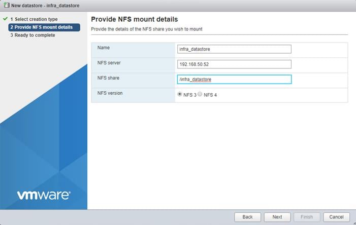
6. Click Finish. The datastore should now appear in the datastore list.
7. In the center pane, choose New Datastore to add a new datastore.
8. In the New datastore popup, choose Mount NFS datastore and click Next.
9. Input infra_swap for the datastore name. Input the IP address for the nfs-lif-01 LIF for the NFS server. Input /infra_swap for the NFS share. Leave the NFS version set at NFS 3. Click Next.
10. Click Finish. The datastore should now appear in the datastore list.
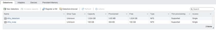
Configure NTP on First ESXi Host
ESXi Host VM-Host-Infra-01
To configure Network Time Protocol (NTP) on the first ESXi host, follow these steps:
1. From the Host Client, choose Manage.
2. In the center pane, choose System > Time & date.
3. Click Edit NTP settings.
4. Make sure “Manually configure the date and time on this host and enter the approximate date and time.
5. Select Use Network Time Protocol (enable NTP client).
6. Use the drop-down list to choose Start and stop with host.
7. Enter the two Nexus switch NTP addresses in the NTP servers box separated by a comma.
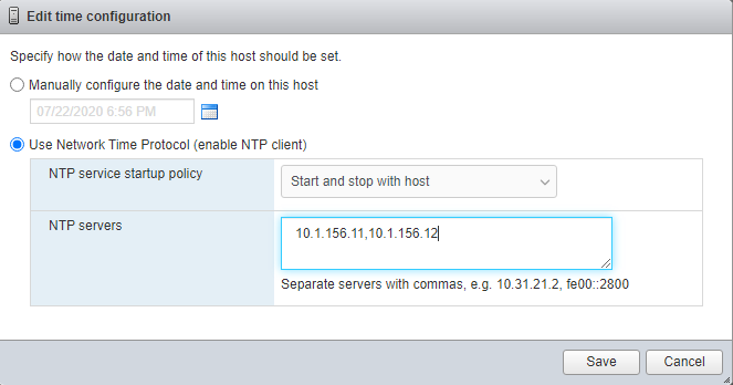
8. Click Save to save the configuration changes.
![]() Currently, it isn’t possible to start NTP from the ESXi Host Client. NTP will be started from vCenter. The NTP server time may vary slightly from the host time.
Currently, it isn’t possible to start NTP from the ESXi Host Client. NTP will be started from vCenter. The NTP server time may vary slightly from the host time.
ESXi Host VM-Host-Infra-01
To configure host swap on the first ESXi host, follow these steps on the host:
1. From the Host Client, choose Manage.
2. In the center pane, choose System > Swap.
3. Click Edit settings.
4. Use the drop-down list to choose infra_swap. Leave all other settings unchanged.
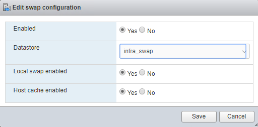
5. Click Save to save the configuration changes.
ESXi Host VM-Host-Infra-01
To configure the host power policy on the first ESXi host, follow these steps on the host:
![]() Implementing this policy is recommended in Performance Tuning Guide for Cisco UCS M5 Servers for maximum VMware ESXi performance. If your organization has specific power policies, please set this policy accordingly.
Implementing this policy is recommended in Performance Tuning Guide for Cisco UCS M5 Servers for maximum VMware ESXi performance. If your organization has specific power policies, please set this policy accordingly.
1. From the Host Client, choose Manage.
2. Go to Hardware > Power Management.
3. Choose Change policy.
4. Choose High performance and click OK.
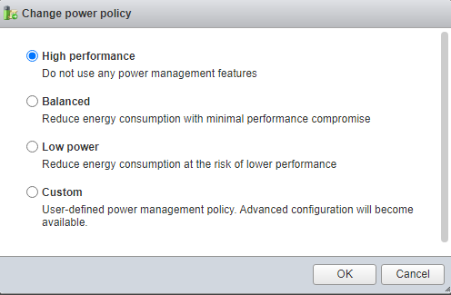
5. If you are implementing iSCSI boot, execute the VMware ESXi setup scripts in the iSCSI Addition Appendix.
VMware vCenter 7.0
The procedures in the following subsections provide detailed instructions for installing the VMware vCenter 7.0D Server Appliance in a FlexPod environment. After the procedures are completed, a VMware vCenter Server will be configured.
Build the VMware vCenter Server Appliance
The VCSA deployment consists of 2 stages: install and configuration. To build the VMware vCenter virtual machine, follow these steps:
1. Locate and copy the VMware-VCSA-all-7.0.0-16749653.iso file to the desktop of the management workstation. This ISO is for the VMware vSphere 7.0 vCenter Server Appliance.
![]() It is important to use at minimum VMware vCenter release 7.0B to ensure access to all needed features.
It is important to use at minimum VMware vCenter release 7.0B to ensure access to all needed features.
2. Using ISO mounting software, mount the ISO image as a disk on the management workstation. (For example, with the Mount command in Windows Server 2012 and above).
3. In the mounted disk directory, navigate to the vcsa-ui-installer > win32 directory and double-click installer.exe. The vCenter Server Appliance Installer wizard appears.
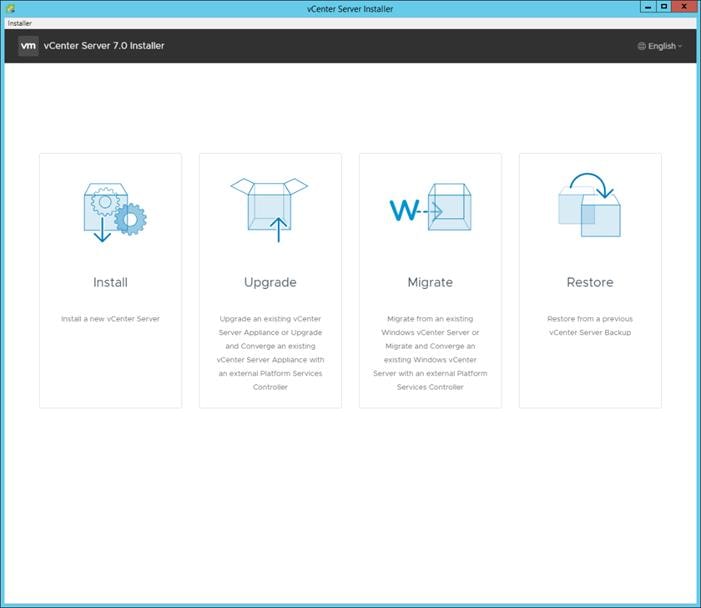
4. Click Install to start the vCenter Server Appliance deployment wizard.
5. Click NEXT in the Introduction section.
6. Read and accept the license agreement and click NEXT.
7. In the “vCenter Server deployment target” window, enter the host name or IP address of the first ESXi host, User name (root) and Password. Click NEXT.
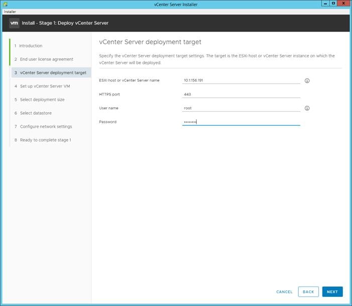
8. Click YES to accept the certificate.
9. Enter the Appliance VM name and password details in the “Set up vCenter Server VM” section. Click NEXT.
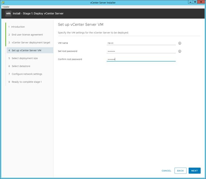
10. In the “Select deployment size” section, choose the Deployment size and Storage size. For example, choose “Small” and “Default”. Click NEXT.
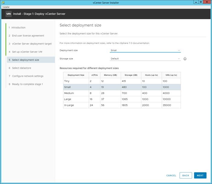
11. Choose infra_datastore for storage. Click NEXT.
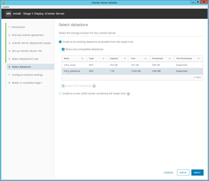
12. In the “Network Settings” section, configure the below settings:
a. Choose a Network: IB-MGMT Network.
![]() It is important that the vCenter VM stay on the IB-MGMT Network on vSwitch0 and that it not get moved to a vDS. If vCenter is moved to a vDS and the virtual environment is completely shut down and then brought back up, and it is attempted to bring up vCenter on a different host than the one it was running on before the shutdown, vCenter will not have a functional network connection. With the vDS, for a virtual machine to move from one host to another, vCenter must be up and running to coordinate the move of the virtual ports on the vDS. If vCenter is down, the port move on the vDS cannot occur correctly. Moving vCenter to a different host on vSwitch0 to be brought up always occurs correctly without requiring vCenter to already be up and running.
It is important that the vCenter VM stay on the IB-MGMT Network on vSwitch0 and that it not get moved to a vDS. If vCenter is moved to a vDS and the virtual environment is completely shut down and then brought back up, and it is attempted to bring up vCenter on a different host than the one it was running on before the shutdown, vCenter will not have a functional network connection. With the vDS, for a virtual machine to move from one host to another, vCenter must be up and running to coordinate the move of the virtual ports on the vDS. If vCenter is down, the port move on the vDS cannot occur correctly. Moving vCenter to a different host on vSwitch0 to be brought up always occurs correctly without requiring vCenter to already be up and running.
b. IP version: IPV4
c. IP assignment: static
d. FQDN: <vcenter-fqdn>
e. IP address: <vcenter-ip>
f. Subnet mask or prefix length: <vcenter-subnet-mask>
g. Default gateway: <vcenter-gateway>
h. DNS Servers: <dns-server1>,<dns-server2>
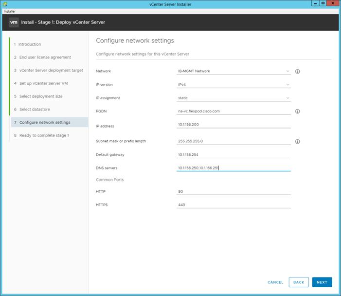
13. Click NEXT.
14. Review all values and click FINISH to complete the installation.
![]() The vCenter Server appliance installation will take a few minutes to complete.
The vCenter Server appliance installation will take a few minutes to complete.
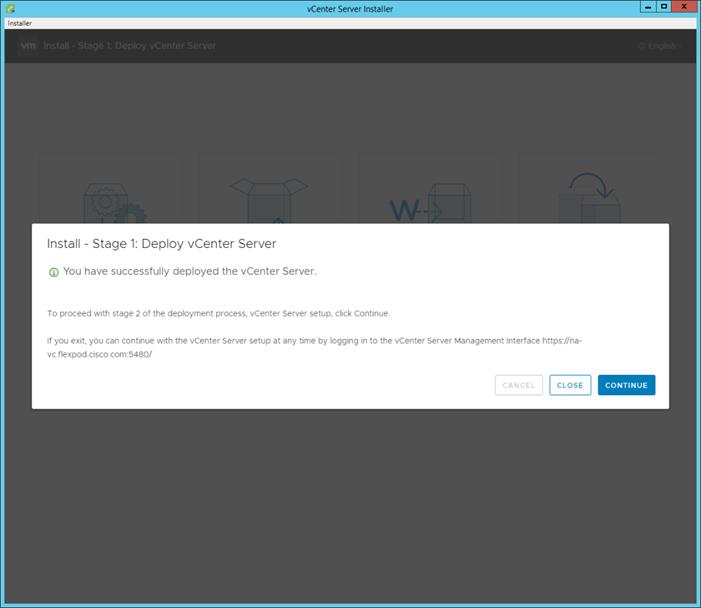
15. Click CONTINUE to proceed with stage 2 configuration.
16. Click NEXT.
17. In the vCenter Server configuration window, configure these settings:
a. Time Synchronization Mode: Synchronize time with NTP servers.
b. NTP Servers: <nexus-a-ntp-ip>,<nexus-b-ntp-ip>
c. SSH access: Enabled.
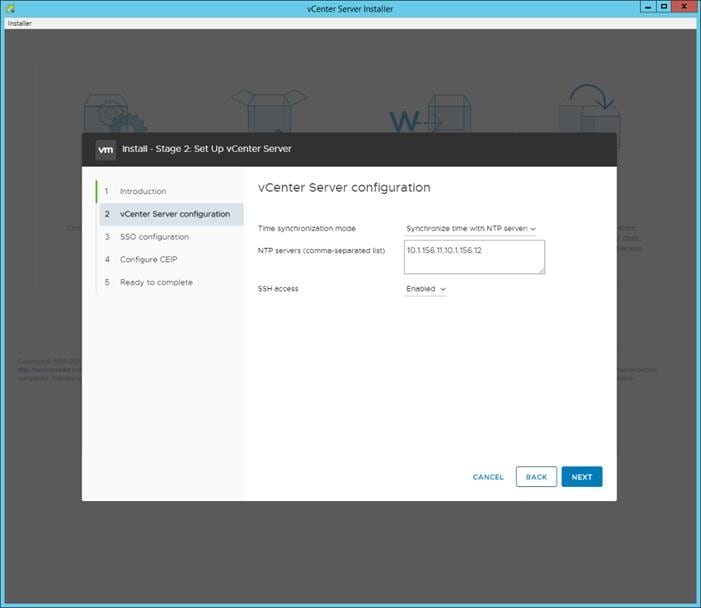
18. Click NEXT.
19. Complete the SSO configuration as shown below or according to your organization’s security policies:
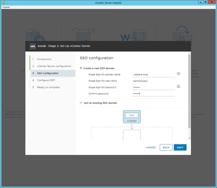
20. Click NEXT.
21. Decide whether to join VMware’s Customer Experience Improvement Program (CEIP).
22. Click NEXT.
23. Review the configuration and click FINISH.
24. Click OK.
![]() vCenter Server setup will take a few minutes to complete.
vCenter Server setup will take a few minutes to complete.
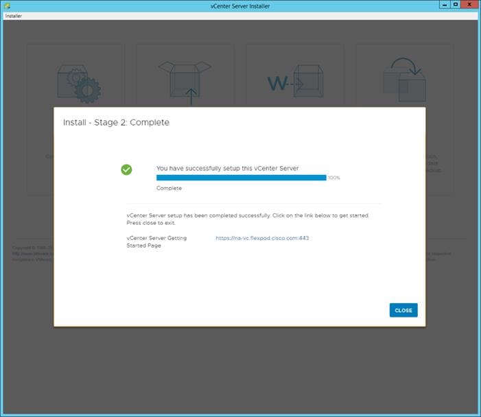
25. Click CLOSE. Eject or unmount the VCSA installer ISO.
If a vCenter deployment size Small or Larger was selected in the vCenter setup, it is possible that the VCSA’s CPU setup does not match the Cisco UCS server CPU hardware configuration. Cisco UCS B and C-Series servers are normally 2-socket servers. In this validation, the Small deployment size was selected and vCenter was setup for a 4-socket server. This setup will cause issues in the VMware ESXi cluster Admission Control. To resolve the Admission Control issue, follow these steps:
1. Open a web browser on the management workstation and navigate to the VM-Host-Infra-01 management IP address.
2. Enter root for the user name.
3. Enter the root password.
4. Click Login to connect.
5. On the left, choose Virtual Machines.
6. In the center pane, right-click the vCenter VM and choose Edit settings.
7. In the Edit settings window, expand CPU and check the value of Sockets.
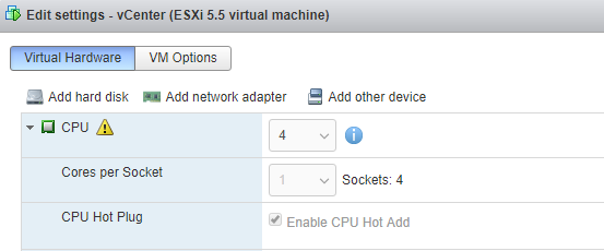
8. If the number of Sockets does not match your server configuration, it will need to be adjusted. Click Cancel.
9. If the number of Sockets needs to be adjusted:
a. Right-click the vCenter VM and choose Guest OS > Shut down. Click Yes on the confirmation.
b. Once vCenter is shut down, right-click the vCenter VM and choose Edit settings.
c. In the Edit settings window, expand CPU and change the Cores per Socket value to make the Sockets value equal to your server configuration (normally 2).
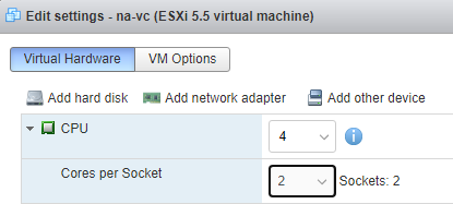
d. Click Save.
e. Right-click the vCenter VM and choose Power > Power on. Wait approximately 10 minutes for vCenter to come up.
To setup the VMware vCenter Server, follow these steps:
1. Using a web browser, navigate to https://<vcenter-ip-address>:5480.
2. Log into the VMware vCenter Server Management interface as root with the root password set in the vCenter installation.
3. In the menu on the left, choose Time.
4. Click EDIT to the right of Time zone.
5. Choose the appropriate Time zone and click SAVE.
6. In the menu on the left choose Administration.
7. According to your Security Policy, adjust the settings for the root user and password.
8. Click Update.
9. Follow the prompts to STAGE AND INSTALL any available vCenter updates. In this validation, vCenter version 7.0.0.10700 was installed.
10. Go to root > Logout to logout of the Appliance Management interface.
11. Using a web browser, navigate to https://<vcenter-fqdn>. You will need to navigate security screens.
![]() With VMware vCenter 7.0, the use of the vCenter FQDN is required.
With VMware vCenter 7.0, the use of the vCenter FQDN is required.
12. Choose LAUNCH VSPHERE CLIENT (HTML5).
![]() Although the previous versions of this document used the FLEX vSphere Web Client, the VMware vSphere HTML5 Client is the only option in vSphere 7 and will be used going forward.
Although the previous versions of this document used the FLEX vSphere Web Client, the VMware vSphere HTML5 Client is the only option in vSphere 7 and will be used going forward.
13. Log in using the Single Sign-On username (administrator@vsphere.local) and password created during the vCenter installation. Dismiss the Licensing warning at this time.
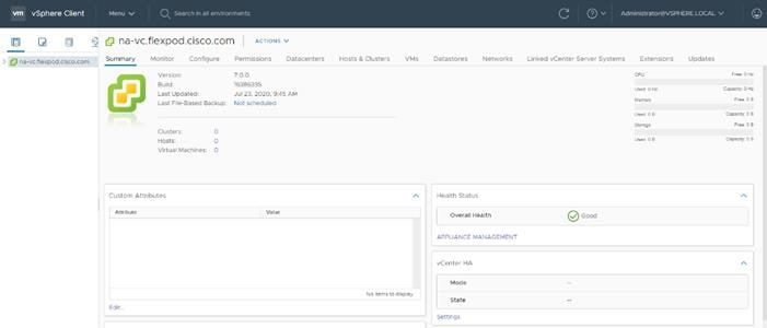
14. Click ACTIONS > New Datacenter.
15. Type “FlexPod-DC” in the Datacenter name field.
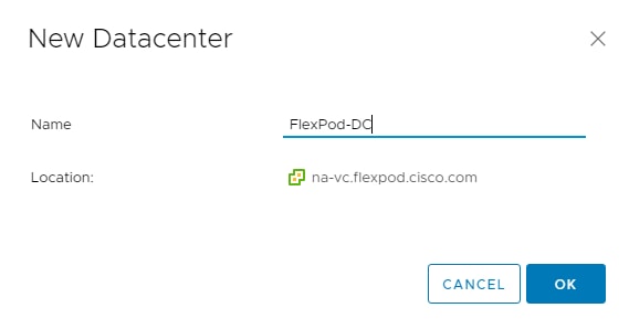
16. Click OK.
17. Expand the vCenter on the left.
18. Right-click the datacenter FlexPod-DC in the list in the left pane. Choose New Cluster.
19. Name the cluster FlexPod-Management.
20. Turn on DRS and vSphere HA. Do not turn on vSAN.
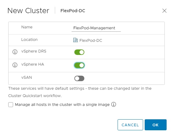
21. Click OK to create the new cluster.
22. Right-click “FlexPod-Management” and choose Settings.
23. Choose Configuration > General in the list located on the left and choose EDIT located on the right of General.
24. Choose Datastore specified by host and click OK.
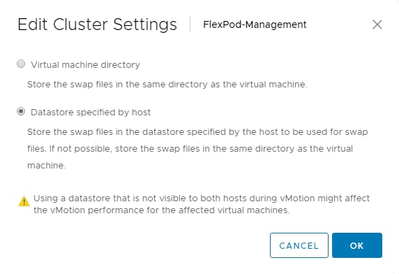
25. Right-click “FlexPod-Management” and click Add Hosts.
26. In the IP address or FQDN field, enter either the IP address or the FQDN of the first VMware ESXi host. Enter root for the Username and the root password. Click NEXT.
27. In the Security Alert window, choose the host and click OK.
28. Verify the Host summary information and click NEXT.
29. Ignore warnings about the host being moved to Maintenance Mode and click FINISH to complete adding the host to the cluster.
30. The added ESXi host will have Warnings that the ESXi Shell and SSH have been enabled. These warnings can be suppressed.
31. In the list, right-click the added ESXi host and choose Settings.
32. In the center pane under Virtual Machines, choose Swap File location.
33. Click EDIT.
34. Choose the infra_swap datastore and click OK.
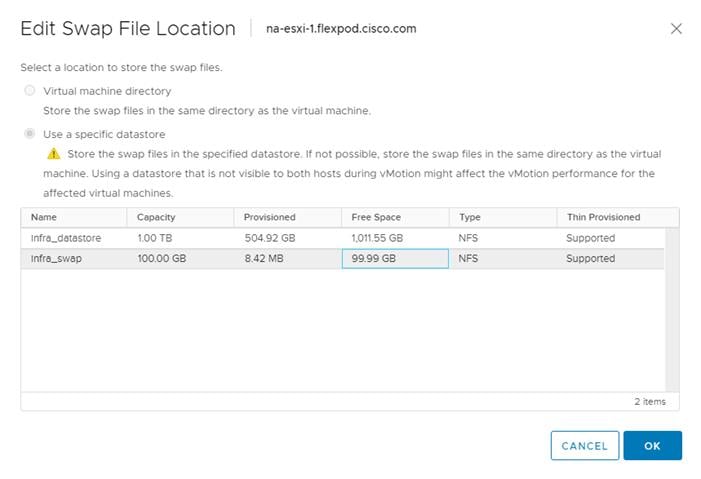
35. In the list under System, choose Time Configuration.
36. Click EDIT to the right of Manual Time Configuration. Set the time and date to the correct local time and click OK.
37. Click EDIT to the right of Network Time Protocol.
38. In the Edit Network Time Protocol window, select Enable and then select Start NTP Service. Ensure the other fields are filled in correctly and click OK.
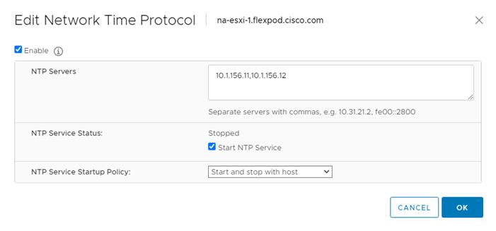
39. In the list under Hardware, choose Overview. Scroll to the bottom and ensure the Power Management Active policy is High Performance. If the Power Management Active policy is not High Performance, to the right of Power Management, choose EDIT POWER POLICY. Choose High performance and click OK.
40. In the list under Storage, choose Storage Devices. Make sure the NETAPP Fibre Channel Disk LUN 0 or NETAPP iSCSI Disk LUN 0 is selected.
41. Click the Paths tab.
42. Ensure that 4 paths appear, two of which should have the status Active (I/O).
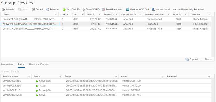
Build the Virtual Machines and Environment
Software Infrastructure Configuration
This section details how to configure the software infrastructure components that comprise this solution. Install and configure the infrastructure virtual machines by following the process provided in Table 17.
Table 17. Test Infrastructure Virtual Machine Configuration
| Configuration |
Citrix Virtual Apps & Desktops Controllers Virtual Machines |
Citrix Provisioning Servers Virtual Machines |
| Operating system |
Microsoft Windows Server 2019 |
Microsoft Windows Server 2019 |
| Virtual CPU amount |
6 |
8 |
| Memory amount |
8 GB |
16 GB |
| Network |
VMXNET3 Infra-Mgmt |
VMXNET3 VDI |
| Disk-1 (OS) size |
40 GB |
40 GB |
| Configuration |
Microsoft Active Directory DCs Virtual Machines |
vCenter Server Appliance Virtual Machine |
| Operating system |
Microsoft Windows Server 2019 |
VCSA – SUSE Linux |
| Virtual CPU amount |
2 |
16 |
| Memory amount |
4 GB |
32 GB |
| Network |
VMXNET3 Infra-Mgmt |
VMXNET3 In-Band-Mgmt |
| Disk size |
40 GB
|
599 GB (across 12 VMDKs)
|
| Configuration |
Microsoft SQL Server Virtual Machine |
Citrix StoreFront Controller Virtual Machine |
| Operating system |
Microsoft Windows Server 2019 Microsoft SQL Server 2012 SP1 |
Microsoft Windows Server 2019 |
| Virtual CPU amount |
6 |
4 |
| Memory amount |
24GB |
8 GB |
| Network |
VMXNET3 Infra-Mgmt |
VMXNET3 Infra-Mgmt |
| Disk-1 (OS) size |
40 GB |
40 GB |
| Disk-2 size |
100 GB SQL Databases\Logs |
- |
This section provides guidance around creating the golden (or master) images for the environment. VMs for the master targets must first be installed with the software components needed to build the golden images. For this CVD, the images contain the basics needed to run the Login VSI workload.
To prepare the master VMs for the Hosted Virtual Desktops (HVDs) and Hosted Shared Desktops (HSDs), there are three major steps: installing the PVS Target Device x64 software, installing the Virtual Delivery Agents (VDAs), and installing application software.
The master target Hosted Virtual Desktop (HVD) and Hosted Shared Desktop (HSD) VMs were configured as listed in Table 18.
Table 18. VDI and RDS Configurations
| Configuration |
HVD Virtual Machines |
HSD Virtual Machines |
| Operating system |
Microsoft Windows 10 64-bit |
Microsoft Windows Server 2019 |
| Virtual CPU amount |
2 |
8 |
| Memory amount |
4 GB memory |
32 GB memory |
| Network |
VMXNET3 DV-VDI |
VMXNET3 DV-VDI |
| Citrix PVS vDisk size Full Clone Disk Size |
24 GB (dynamic) 45 GB |
40 GB (dynamic)
|
| Citrix PVS write cache Disk size |
6 GB |
30 GB |
| Citrix PVS write cache RAM cache size |
256 MB |
1024 MB |
| Additional software used for testing |
Microsoft Office 2016 Login VSI 4.1.40 (Knowledge Worker Workload) |
Microsoft Office 2016 Login VSI 4.1.40 (Knowledge Worker Workload) |
Install and Configure Citrix Virtual Apps & Desktops and RDS
This section details the installation of the core components of the Citrix Virtual Apps & Desktops/RDS 1912 LTSR system. This CVD installs two Citrix Virtual Apps & Desktops Delivery Controllers to support both hosted shared desktops (HSD), non-persistent hosted virtual desktops (HVD), and persistent hosted virtual desktops (HVD).
Citrix recommends that you use Secure HTTP (HTTPS) and a digital certificate to protect vSphere communications. Citrix recommends that you use a digital certificate issued by a certificate authority (CA) according to your organization's security policy. Otherwise, if security policy allows, use the VMware-installed self-signed certificate.
To install vCenter Server self-signed Certificate, follow these steps:
1. Add the FQDN of the computer running vCenter Server to the hosts file on that server, located at SystemRoot/
WINDOWS/system32/Drivers/etc/. This step is required only if the FQDN of the computer running vCenter Server is not already present in DNS.
2. Open Internet Explorer and enter the address of the computer running vCenter Server (e.g., https://FQDN for the URL).
3. Accept the security warnings.
4. Click the Certificate Error in the Security Status bar and select View certificates.
5. Click Install certificate, select Local Machine, and then click Next.
6. Select Place all certificates in the following store and then click Browse.
7. Select Show physical stores.
8. Select Trusted People.
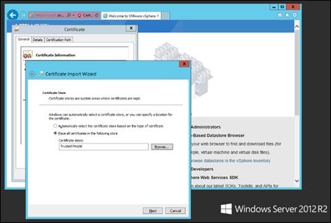
9. Click Next and then click Finish.
10. Perform the above steps on all Delivery Controllers and Provisioning Servers.
Install and Configure Citrix Desktop Delivery Controller, Citrix Licensing, and StoreFront
This section details the installation of the core components of the Citrix Virtual Apps and Desktops 1912 LTSR system. This CVD provides the process to install two Desktop Delivery Controllers to support hosted shared desktops (HSD), non-persistent virtual desktops (VDI), and persistent virtual desktops (VDI).
The process of installing the Desktop Delivery Controller also installs other key Citrix Desktop software components, including Studio, which is used to create and manage infrastructure components, and Director, which is used to monitor performance and troubleshoot problems.
To install the Citrix License Server, follow these steps:
1. To begin the installation, connect to the first Citrix License server and launch the installer from the Citrix Virtual Apps and Desktops 1912 LTSR ISO.
2. Click Start.

3. Click “Extend Deployment – Citrix License Server.”

4. Read the Citrix License Agreement. If acceptable, indicate your acceptance of the license by selecting the “I have read, understand, and accept the terms of the license agreement” radio button.
5. Click Next.
6. Click Next.
7. Select the default ports and automatically configured firewall rules.
8. Click Next.
9. Click Install.
10. Click Finish to complete the installation.
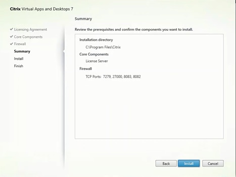
To install the Citrix Licenses, follow these steps:
1. Copy the license files to the default location (C:\Program Files (x86)\Citrix\Licensing\ MyFiles) on the license server.
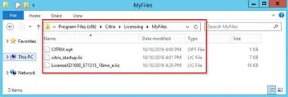
2. Restart the server or Citrix licensing services so that the licenses are activated.
3. Run the application Citrix License Administration Console.
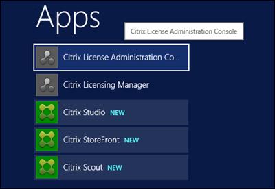
4. Confirm that the license files have been read and enabled correctly.
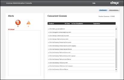
Install Citrix Desktop Broker/Studio
To install Citrix Desktop, follow these steps:
1. Connect to the first Citrix VDI server and launch the installer from the Citrix Desktop 1912 LTSR ISO.
2. Click Start.

The installation wizard presents a menu with three subsections.
3. Click “Get Started - Delivery Controller.”
4. Read the Citrix License Agreement and if acceptable, indicate your acceptance of the license by selecting the “I have read, understand, and accept the terms of the license agreement” radio button.
5. Click Next.
6. Select the components to be installed on the first Delivery Controller Server:
a. Delivery Controller
b. Studio
c. Director
7. Click Next.
![]() Dedicated StoreFront and License servers should be implemented for large-scale deployments.
Dedicated StoreFront and License servers should be implemented for large-scale deployments.
8. Since a SQL Server will be used to Store the Database, leave “Install Microsoft SQL Server 2017 CU16 Express” unchecked.
9. Click Next.
10. Select the default ports and automatically configured firewall rules.
11. Click Next.
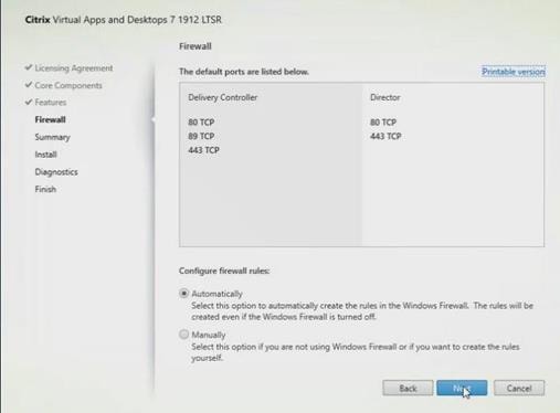
12. Click Install.
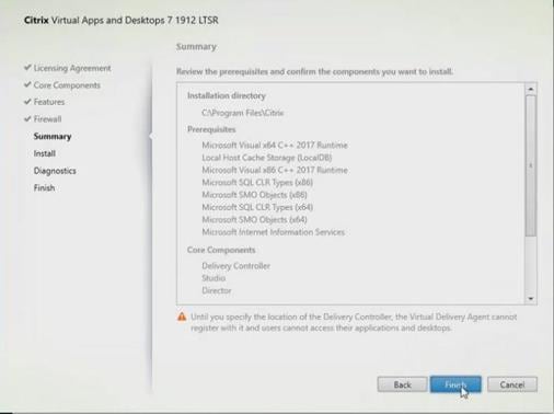
13. (Optional) Click the Call Home participation.
14. Click Next.
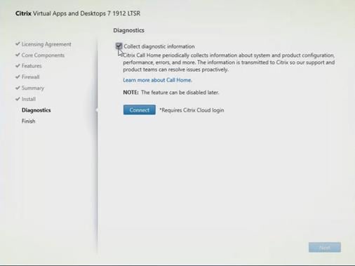
15. Click Finish to complete the installation.
16. (Optional) Check Launch Studio to launch Citrix Studio Console.
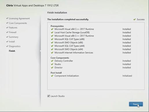
Citrix Studio is a management console that allows you to create and manage infrastructure and resources to deliver desktops and applications. Replacing Desktop Studio from earlier releases, it provides wizards to set up your environment, create workloads to host applications and desktops, and assign applications and desktops to users.
Citrix Studio launches automatically after the Citrix VDI Delivery Controller installation, or if necessary, it can be launched manually. Citrix Studio is used to create a Site, which is the core Citrix VDI environment consisting of the Delivery Controller and the Database.
To configure Citrix VDI, follow these steps:
1. From Citrix Studio, click Deliver applications and desktops to your users.
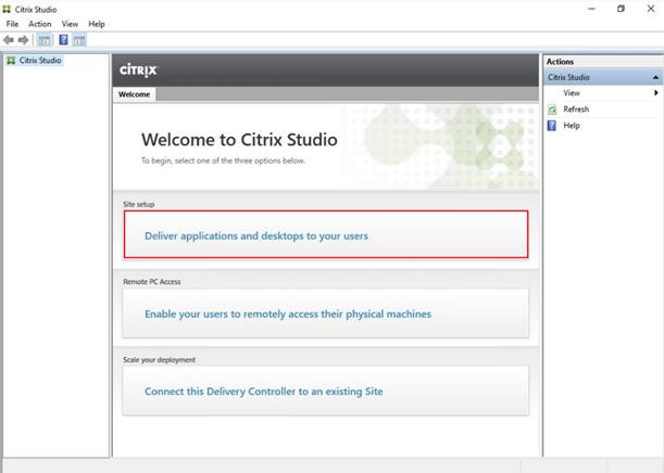
2. Select the “A fully configured, production-ready Site” radio button.
3. Enter a site name.
4. Click Next.
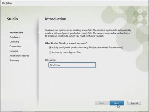
5. Provide the Database Server Locations for each data type and click Next.
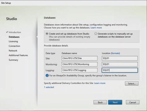
6. For an AlwaysOn Availability Group, use the group’s listener DNS name.
7. Provide the FQDN of the license server.
8. Click Connect to validate and retrieve any licenses from the server.
![]() If no licenses are available, you can use the 30-day free trial or activate a license file.
If no licenses are available, you can use the 30-day free trial or activate a license file.
9. Select the appropriate product edition using the license radio button.
10. Click Next.
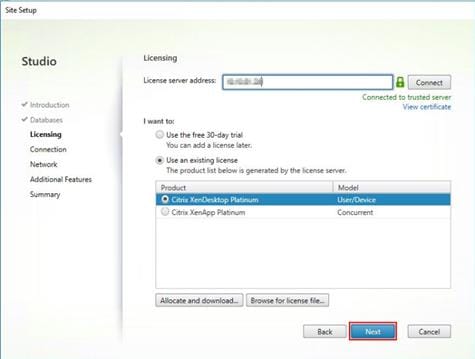
11. Select the Connection type of ‘Microsoft System Center Virtual Machine Manager’.
12. Enter the Connection Address to the VCenter Server Appliance.
13. Enter the username (in username@domain format) for the vCenter account.
14. Provide the password for the VCenter Admin account.
15. Provide a connection name.
16. Select the Studio tools radio button.
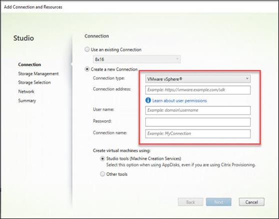
17. Click Next.
18. Select the FlexPod Cluster that will be used by this connection.
19. Check Studio Tools radio button required to support desktop provisioning task by this connection.
20. Click Next.
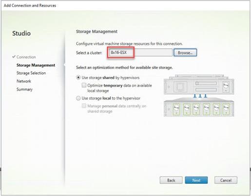
21. Make Storage selection to be used by this connection.
22. Click Next.
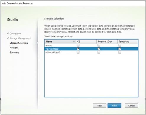
23. Select the Network to be used by this connection.
24. Click Next.
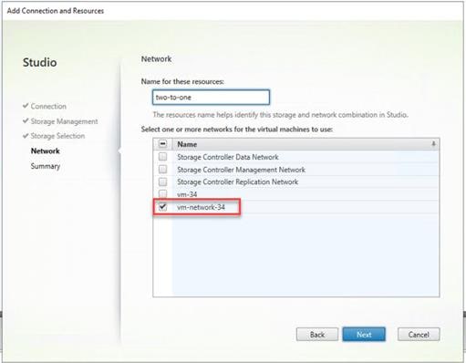
25. Select Additional features.
26. Click Next.
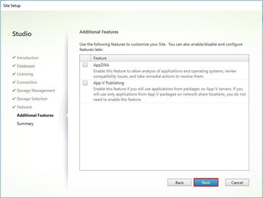
27. Review Site configuration Summary and click Finish.
Configure the Citrix VDI Site Administrators
To configure the Citrix VDI site administrators, follow these steps:
1. Connect to the Citrix VDI server and open Citrix Studio Management console.
2. From the Configuration menu, right-click Administrator and select Create Administrator from the drop-down list.
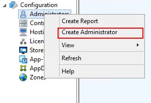
3. Select/Create appropriate scope and click Next.
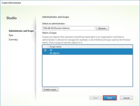
4. Choose an appropriate Role.
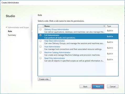
5. Review the Summary, check Enable administrator, and click Finish.
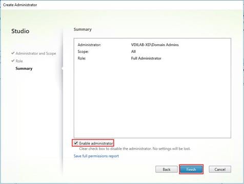
Configure Additional Desktop Controller
After the first controller is completely configured and the Site is operational, you can add additional controllers.
![]() In this CVD, we created 5 Delivery Controllers. Citrix recommends 1 Delivery Controller per 1000 users
In this CVD, we created 5 Delivery Controllers. Citrix recommends 1 Delivery Controller per 1000 users
To configure additional Citrix Desktop controllers, follow these steps:
1. To begin the installation of the second Delivery Controller, connect to the second Citrix VDI server and launch the installer from the Citrix Virtual Apps and Desktops ISO.
2. Click Start.
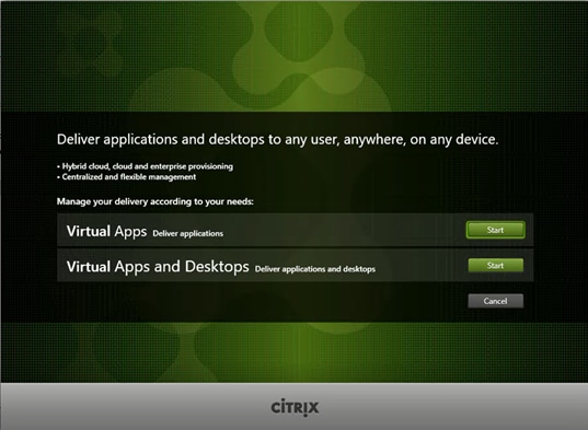
3. Click Delivery Controller.

4. Repeat these steps used to install the first Delivery Controller, including the step of importing an SSL certificate for HTTPS between the controller and Hyper-V.
5. Review the Summary configuration.
6. Click Install.
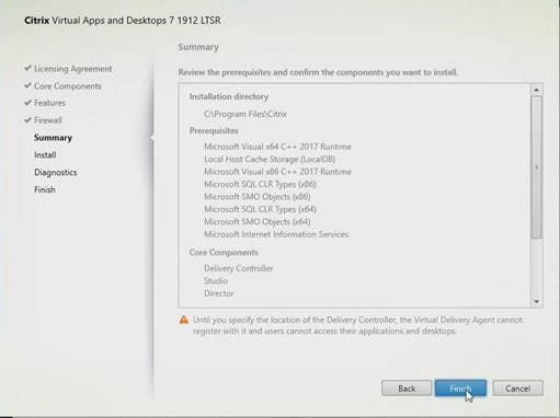
7. (Optional) Click the “Collect diagnostic information.”
8. Click Next.
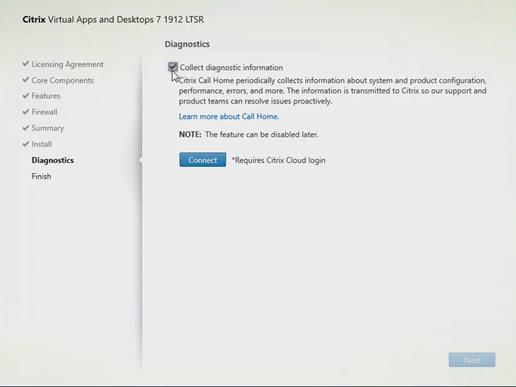
9. Verify the components installed successfully.
10. Click Finish.
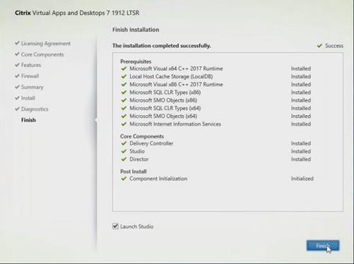
Add the Second Delivery Controller to the Citrix Desktop Site
To add the second Delivery Controller to the Citrix Desktop Site, follow these steps:
1. In Desktop Studio, click Connect this Delivery Controller to an existing Site.
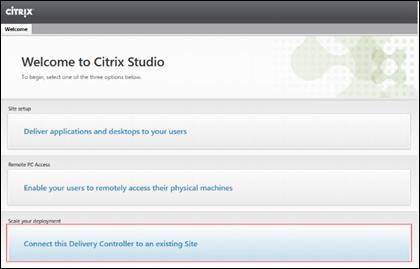
2. Enter the FQDN of the first delivery controller.
3. Click OK.
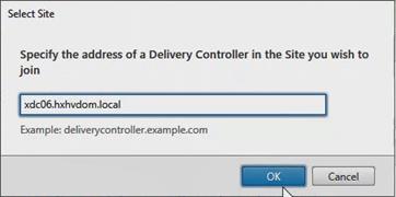
4. Click Yes to allow the database to be updated with this controller’s information automatically.
5. When complete, test the site configuration and verify the Delivery Controller has been added to the list of Controllers.
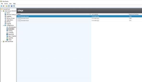
Install and Configure StoreFront
Citrix StoreFront stores aggregate desktops and applications from Citrix VDI sites, making resources readily available to users.
![]() In this CVD, we created two StoreFront servers on dedicated virtual machines.
In this CVD, we created two StoreFront servers on dedicated virtual machines.
To install and configure StoreFront, follow these steps:
1. To begin the installation of the StoreFront, connect to the first StoreFront server and launch the installer from the Citrix Desktop 1912 LTSR ISO.
2. Click Start.
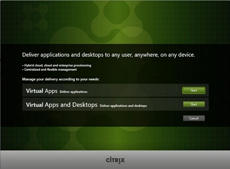
3. Click Extend Deployment Citrix StoreFront.
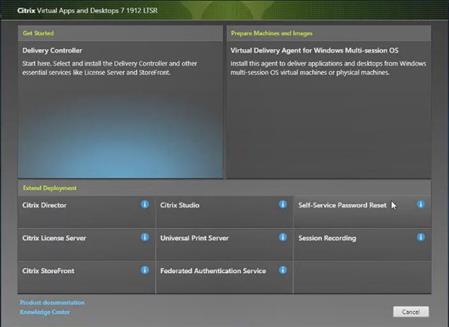
4. If acceptable, indicate your acceptance of the license by selecting the “I have read, understand, and accept the terms of the license agreement” radio button.
5. Click Next.

6. Select Storefront and click Next.
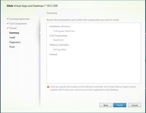
7. Select the default ports and automatically configured firewall rules.
8. Click Next.
9. Click Install.
10. (Optional) Click Collect diagnostic information.
11. Click Next.
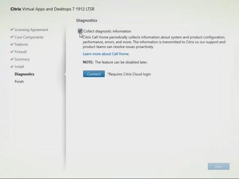
12. Click Finish.
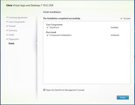
13. Click Create a new deployment.
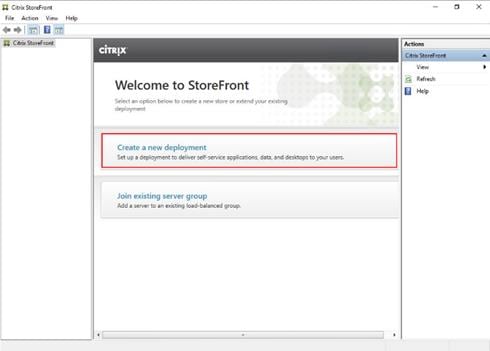
14. Specify the URL of the StoreFront server and click Next.
![]() For a multiple server deployment use the load balancing environment in the Base URL box.
For a multiple server deployment use the load balancing environment in the Base URL box.
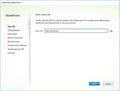
15. Click Next.
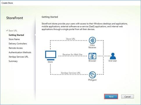
16. Specify a name for your store and click Next.
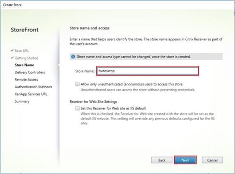
17. Add the required Delivery Controllers to the store and click Next.
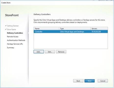
18. Specify how connecting users can access the resources, in this environment only local users on the internal network are able to access the store and click Next.
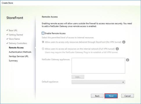
19. On the “Authentication Methods” page, select the methods your users will use to authenticate to the store and click Next. You can select from the following methods as shown below:
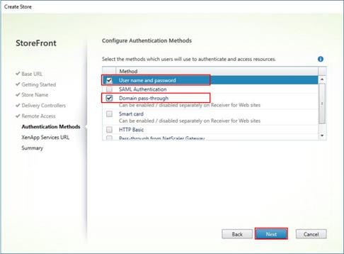
20. Username and password: Users enter their credentials and are authenticated when they access their stores.
21. Domain pass-through: Users authenticate to their domain-joined Windows computers and their credentials are used to log them on automatically when they access their stores.
22. Configure the XenApp Service URL for users who use PNAgent to access the applications and desktops and click Create.
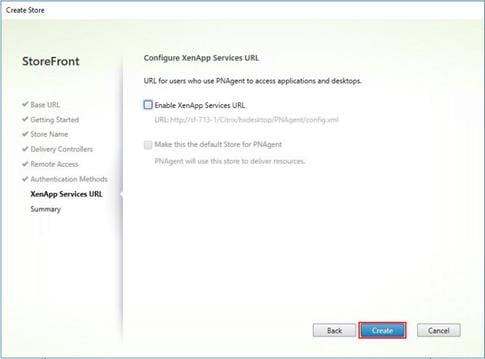
23. After creating the store click Finish.
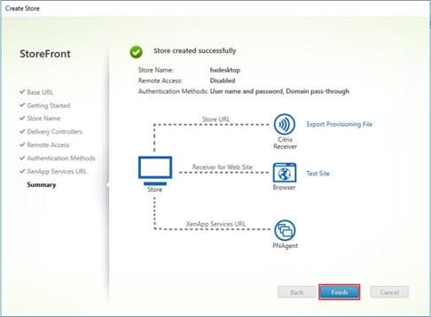
Additional StoreFront Configuration
After the first StoreFront server is completely configured and the Store is operational, you can add additional servers.
To configure additional StoreFront server, follow these steps:
1. To begin the installation of the second StoreFront, connect to the second StoreFront server and launch the installer from the Citrix VDI ISO.
2. Click Start.

3. Click Extended Deployment Citrix StoreFront.

4. Repeat steps 1-3 used to install the first StoreFront.
5. Review the Summary configuration.
6. Click Install.
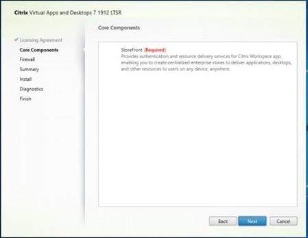
7. (Optional) Click Collect diagnostic information.
8. Click Next.
9. Check Open the StoreFront Management Console.
10. Click Finish.
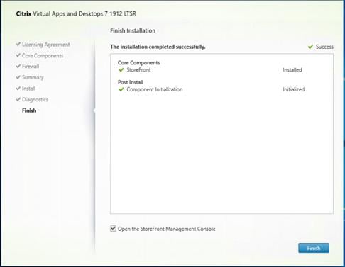
To configure the second StoreFront if used, follow these steps:
1. From the StoreFront Console on the second server, select Join existing server group.
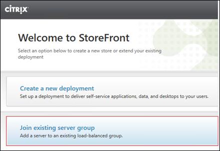
2. In the Join Server Group dialog, enter the name of the first Storefront server.
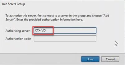
3. Before the additional StoreFront server can join the server group, you must connect to the first Storefront server, add the second server, and obtain the required authorization information.
4. Connect to the first StoreFront server.
5. Using the StoreFront menu on the left, you can scroll through the StoreFront management options.
6. Select Server Group from the menu.
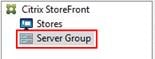
7. To add the second server and generate the authorization information that allows the additional StoreFront server to join the server group, select Add Server.
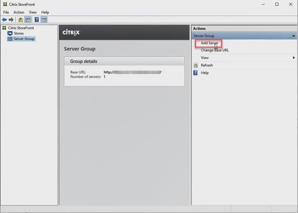
8. Copy the Authorization code from the Add Server dialog.
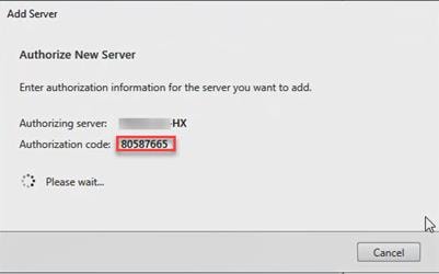
9. Connect to the second Storefront server and paste the Authorization code into the Join Server Group dialog.
10. Click Join.
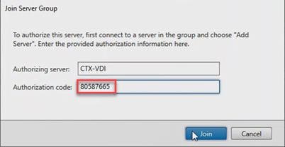
11. A message appears when the second server has joined successfully.
12. Click OK.
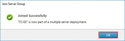
The second StoreFront is now in the Server Group.
Install the Citrix Provisioning Services Target Device Software
For non-persistent Windows 10 virtual desktops and Server 2019 RDS virtual machines, Citrix Provisioning Services (PVS) is used for deployment. The Master Target Device refers to the target device from which a hard disk image is built and stored on a vDisk. Provisioning Services then streams the contents of the vDisk created to other target devices. This procedure installs the PVS Target Device software that is used to build the RDS and VDI golden images.
To install the Citrix Provisioning Server Target Device software, follow these steps:
![]() The instructions below outline the installation procedure to configure a vDisk for VDI desktops. When you have completed these installation steps, repeat the procedure to configure a vDisk for RDS.
The instructions below outline the installation procedure to configure a vDisk for VDI desktops. When you have completed these installation steps, repeat the procedure to configure a vDisk for RDS.
1. On the Window 10 Master Target Device, launch the PVS installer from the Provisioning Services ISO.
2. Click Target Device Installation.
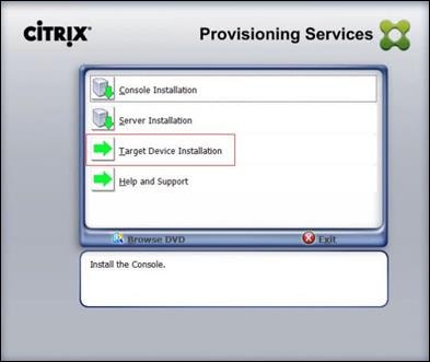
![]() The installation wizard will check to resolve dependencies and then begin the PVS target device installation process.
The installation wizard will check to resolve dependencies and then begin the PVS target device installation process.
3. Click Next.
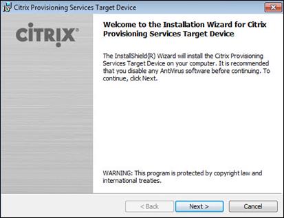
4. Confirm the installation settings and click Install.
5. Deselect the checkbox to launch the Imaging Wizard and click Finish.
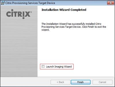
6. Reboot the machine.
Create Citrix Provisioning Services vDisks
The PVS Imaging Wizard automatically creates a base vDisk image from the master target device. To create the Citrix Provisioning Server vDisks, follow these steps:
![]() The following procedure explains how to create a vDisk for VDI desktops. When you have completed these steps, repeat the procedure to build a vDisk for RDS.
The following procedure explains how to create a vDisk for VDI desktops. When you have completed these steps, repeat the procedure to build a vDisk for RDS.
1. The PVS Imaging Wizard's Welcome page appears.
2. Click Next.
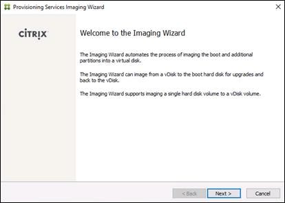
3. The Connect to Farm page appears. Enter the name or IP address of a Provisioning Server within the farm to connect to and the port to use to make that connection.
4. Use the Windows credentials (default) or enter different credentials.
5. Click Next.
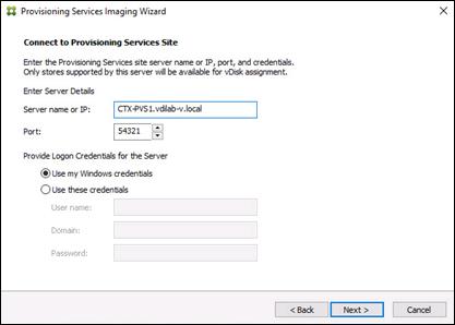
6. Click Create new vDisk.
7. Click Next.
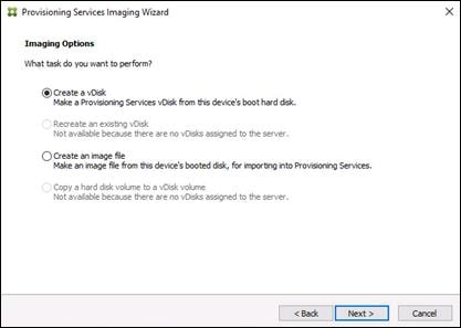
8. The Add Target Device page appears.
9. Select the Target Device Name, the MAC address associated with one of the NICs that was selected when the target device software was installed on the master target device, and the Collection to which you are adding the device.
10. Click Next.
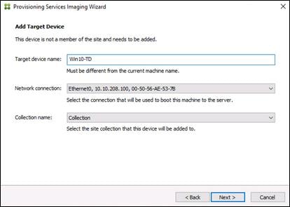
11. The New vDisk dialog displays. Enter the name of the vDisk.
12. Select the Store where the vDisk will reside. Select the vDisk type, either Fixed or Dynamic, from the drop-down list. (This CVD used Dynamic rather than Fixed vDisks.)
13. Click Next.
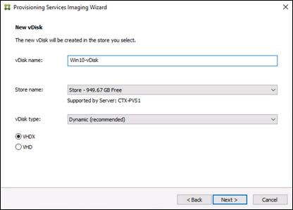
14. On the Microsoft Volume Licensing page, select the volume license option to use for target devices. For this CVD, volume licensing is not used, so the None button is selected.
15. Click Next.
16. Select Image entire boot disk on the Configure Image Volumes page.
17. Click Next.
18. Select Optimize for hard disk again for Provisioning Services before imaging on the Optimize Hard Disk for Provisioning Services.
19. Click Next.
20. Click Create on the Summary page.
21. Review the configuration and click Continue.
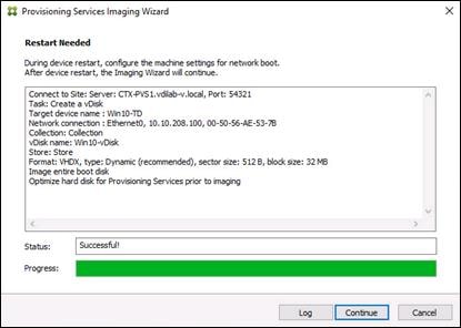
22. When prompted, click No to shut down the machine.
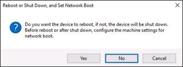
23. Edit the virtual machine settings and select Boot options under VM Options.
24. Click Force BIOS setup and click OK.
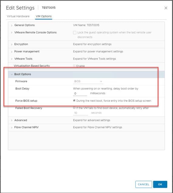
25. Restart the Virtual Machine.
26. When the VM boots into the BIOS, go to the Boot menu to move the Network boot from VMware VMXNET3 to the top of the list.
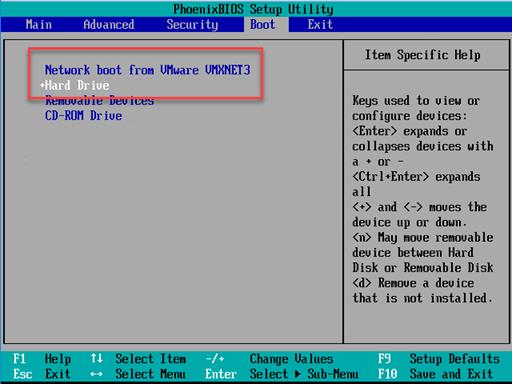
25. Restart the Virtual Machine
![]() After restarting the virtual machine, log into the VDI or RDS master target. The PVS imaging process begins, copying the contents of the C: drive to the PVS vDisk located on the server.
After restarting the virtual machine, log into the VDI or RDS master target. The PVS imaging process begins, copying the contents of the C: drive to the PVS vDisk located on the server.
27. If prompted to Restart select Restart Later.
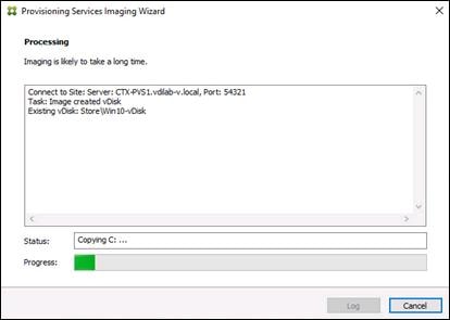
28. A message is displayed when the conversion is complete, click Done.
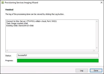
29. Shutdown the virtual machine used for the VDI or RDS master target.
30. Connect to the PVS server and validate that the vDisk image is available in the Store.
31. Right-click the newly created vDisk and select Properties.
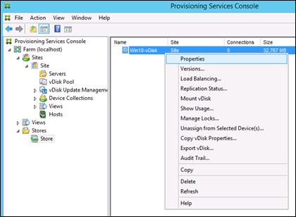
32. On the vDisk Properties dialog, change Access mode to Private mode so the Citrix Virtual Desktop Agent can be installed.
Install Citrix Virtual Apps and Desktop Virtual Desktop Agents
Virtual Delivery Agents (VDAs) are installed on the server and workstation operating systems and enable connections for desktops and apps. The following procedure was used to install VDAs for both HVD and HSD environments.
To install Citrix Desktop Virtual Desktop Agents, follow these steps:
1. Launch the Citrix Desktop installer from the CVA Desktop 1912 LTSR CU2 ISO.
2. Click Start on the Welcome Screen.
3. To install the VDA for the Hosted Virtual Desktops (VDI), select Virtual Delivery Agent for Windows Desktop OS. After the VDA is installed for Hosted Virtual Desktops, repeat the procedure to install the VDA for Hosted Shared Desktops (RDS). In this case, select Virtual Delivery Agent for Windows Server OS and follow the same basic steps.
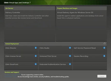
4. Select Create a Master Image. Be sure to select the proper provisioning technology here.
5. Click Next.
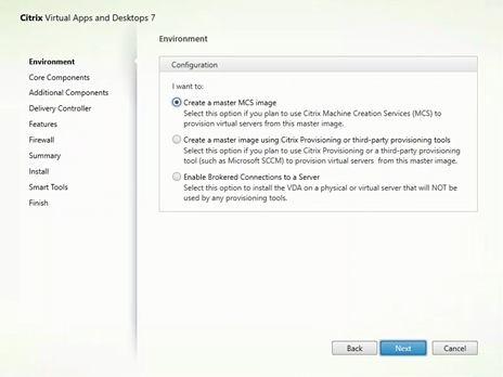
6. Optional: Select Citrix Workspace App.
7. Click Next.
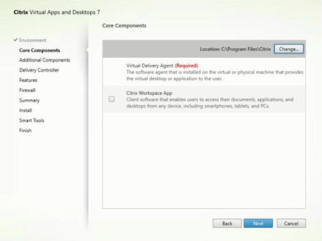
8. Click Next.
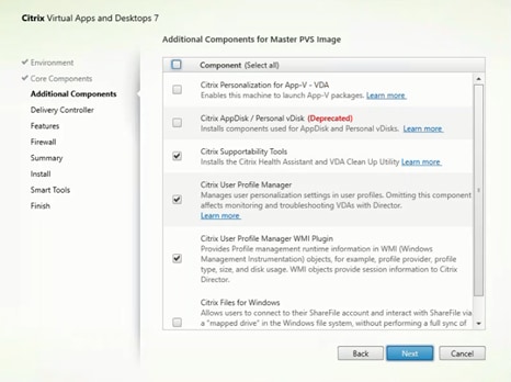
9. Select Do it manually and specify the FQDN of the Delivery Controllers.
10. Click Next.
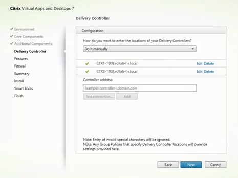
11. Accept the default features.
12. Click Next.
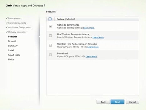
13. Allow the firewall rules to be configured automatically.
14. Click Next.
15. Verify the Summary and click Install.
16. (Optional) Select Call Home participation.
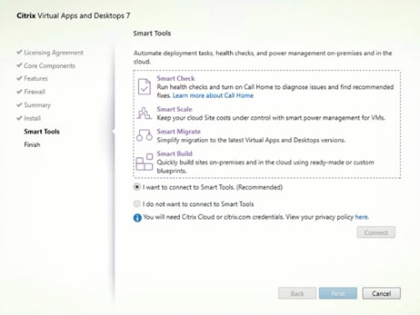
17. (Optional) Click Restart Machine.
18. Click Finish.
19. Repeat steps 1-18 so that VDAs are installed for both HVD (using the Windows 10 OS image) and the HSD desktops (using the Windows Server 2019 image).
20. Select an appropriate workflow for the HSD desktop.
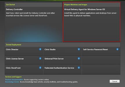
21. When the Citrix VDA is installed, on the vDisk Properties dialog, change Access mode to Standard Image (multi-device, read-only access).
22. Set the Cache Type to Cache in device RAM with overflow on hard disk.
23. Set Maximum RAM size (MBs): 256 for VDI and set 1024 MB for RDS vDisk.
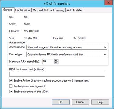
24. Click OK.
![]() Repeat steps 1-23 to create vDisks for both the Hosted VDI Desktops (using the Windows 10 OS image) and the Hosted Shared Desktops (using the Windows Server 2019 image).
Repeat steps 1-23 to create vDisks for both the Hosted VDI Desktops (using the Windows 10 OS image) and the Hosted Shared Desktops (using the Windows Server 2019 image).
Provision Virtual Desktop Machines
To create VDI and RDS machines, follow these steps:
1. Select the Master Target Device virtual machine from the VCenter Client.
2. Right-click the virtual machine and go to Clone -> Clone to Template.
3. Name the clone Template.
4. Select the cluster and datastore where the first phase of provisioning will occur.
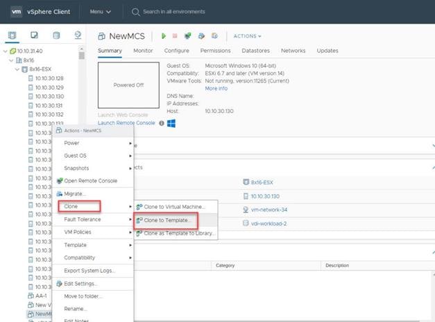
5. Name the template and click Next.
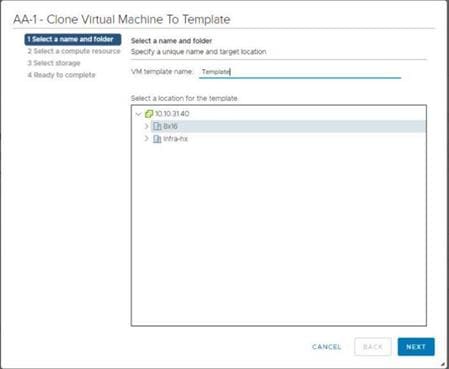
6. Select a host in the cluster to place the template.
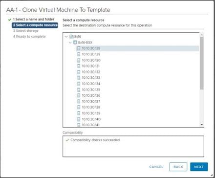
7. Click Next after selecting a datastore.
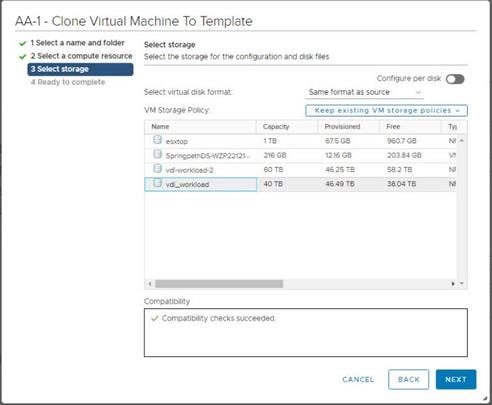
8. Click Next.
9. Click Next through the remaining screens
10. Click Finish to create the template.
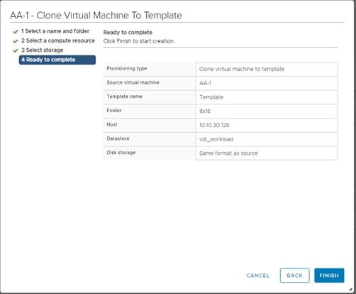
11. From Citrix Studio on the Desktop Controller, select Hosting and Add Connection and Resources.
12. Select Use an existing Connection and click Next.
13. Correspond the name of the resource with desktop machine clusters.
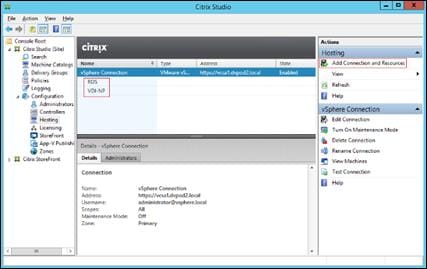
14. Browse and select the VCenter cluster for desktop provisioning and use the default storage method Use storage shared by hypervisors.
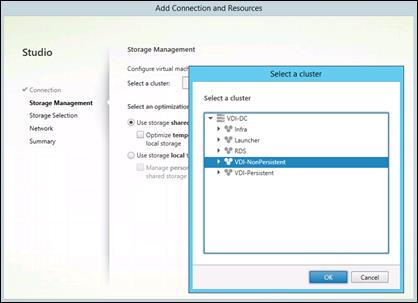
15. Select the data storage location for the corresponding resource.
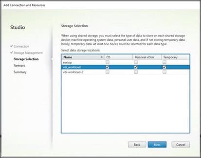
16. Select the VDI networks for the desktop machines and click Next.
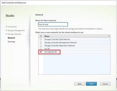
17. Click Finish.
![]() Return to these settings to alter the datastore selection for each set of provisioned desktop machines if you want to create a separate datastore for each image
Return to these settings to alter the datastore selection for each set of provisioned desktop machines if you want to create a separate datastore for each image
Provision Desktop Machines from Citrix Provisioning Services Console
To provision the desktop machines using the Citrix Provisioning Service Console, follow these steps:
1. Start the Virtual Desktops Setup Wizard from the Provisioning Services Console.
2. Right-click Site.
3. Choose Virtual Desktops Setup Wizard… from the context menu.
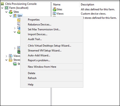
4. Click Next.
5. Enter the Virtual Desktops Controller address that will be used for the wizard operations.
6. Click Next.
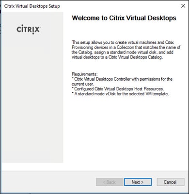
7. Select the Host Resources on which the virtual machines will be created.
8. Click Next.
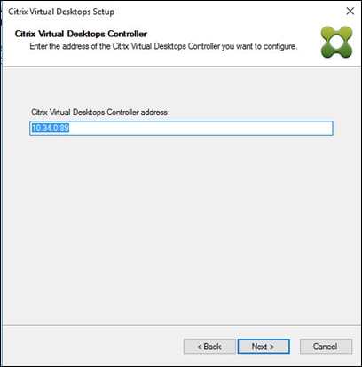
9. Provide the Host Resources Credentials (Username and Password) to the Virtual Desktops controller when prompted.
10. Click OK.
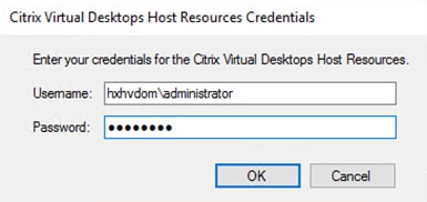
11. Select the Template created earlier.
12. Click Next.
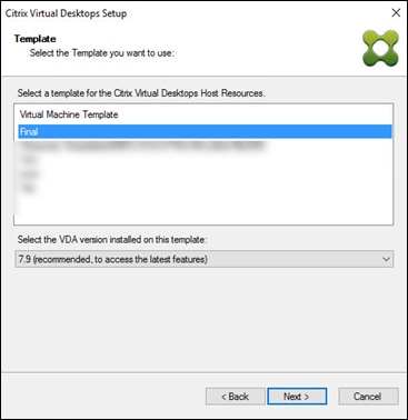
13. Select the vDisk that will be used to stream virtual machines.
14. Click Next.
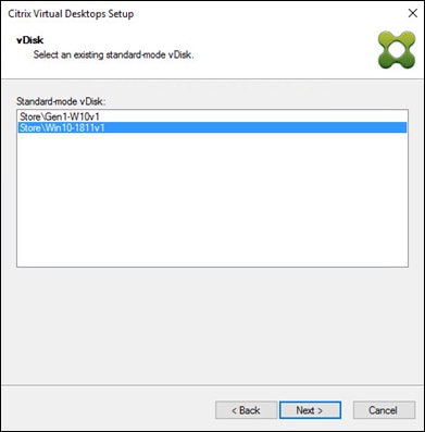
15. Select Create a new catalog.
![]() The catalog name is also used for the collection name in the PVS site.
The catalog name is also used for the collection name in the PVS site.
16. Click Next.
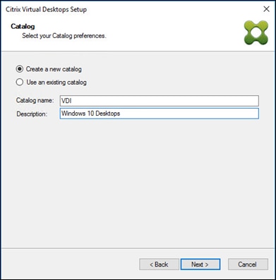
17. On the Operating System dialog, specify the operating system for the catalog. Specify Windows Desktop Operating System for VDI and Windows Server Operating System for RDS.
18. Click Next.
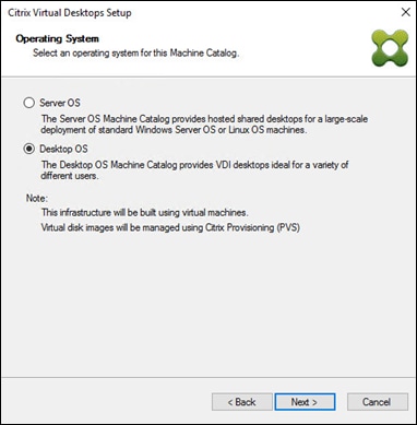
19. If you specified a Windows Desktop OS for VDIs, a User Experience dialog appears. Specify that the user will connect to “A fresh new (random) desktop each time.”
20. Click Next.
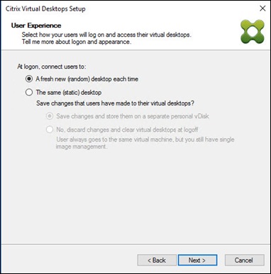
21. On the Virtual machines dialog, specify:
a. The number of virtual machines to create.
b. Number of vCPUs for the virtual machine (2 for VDI, 8 for RDS).
c. The amount of memory for the virtual machine (4GB for VDI, 24GB for RDS).
d. The write-cache disk size (10GB for VDI, 30GB for RDS).
e. PXE boot for the Boot Mode.
22. Click Next.
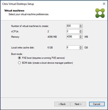
23. Select Create new accounts radio.
24. Click Next.
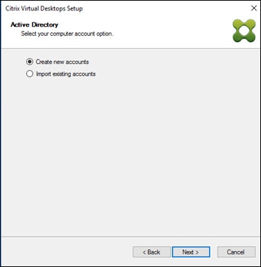
25. Specify the Active Directory Accounts and Location. This is where the wizard should create the computer accounts.
26. Provide the Account naming scheme. An example name is shown in the text box below the name scheme selection location.
27. Click Next.
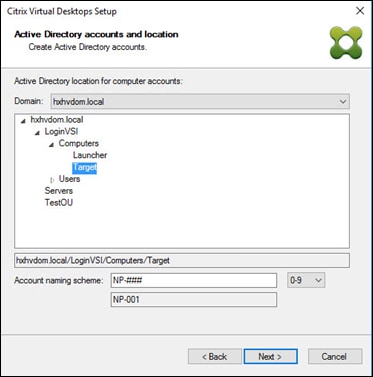
28. Click Finish to begin the virtual machine creation.
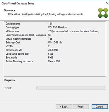
29. When the wizard is done provisioning the virtual machines, click Done.
30. Verify the desktop machines were successfully created in the following locations:
a. PVS1 > Provisioning Services Console > Farm > Site > Device Collections > VDI-NP > CTX-VDI-001
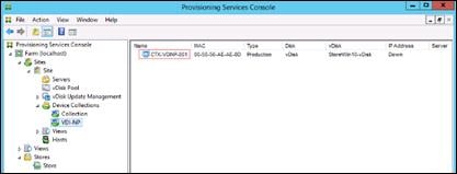
b. CTX-XD1 > Citrix Studio > Machine Catalogs > VDI-NP
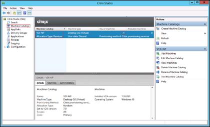
c. AD-DC1 > Active Directory Users and Computers > hxhvdom.local > Computers > CTX-VDI-001
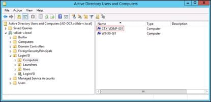
31. Log into the newly provisioned desktop machine, using the Virtual Disk Status verify the image mode is set to Ready Only and the cache type as Device Ram with overflow on local hard drive.
Citrix Machine Creation Services
To create the Citrix Machine services, follow these steps:
1. Connect to a Citrix Virtual Apps & Desktops server and launch Citrix Studio.
2. Choose Create Machine Catalog from the Actions pane.
3. Click Next.
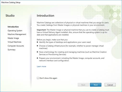
4. Select Desktop OS.
5. Click Next.
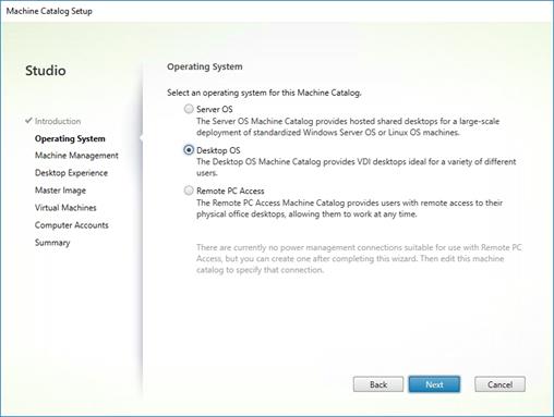
6. Select the appropriate machine management.
7. Click Next.
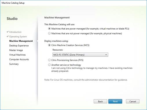
8. Select Static, Dedicated Virtual Machine for Desktop Experience.
9. Click Next.
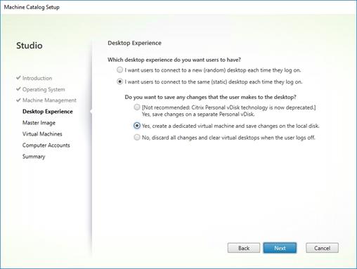
10. Select a Virtual Machine to be used for Catalog Master Image.
11. Click Next.
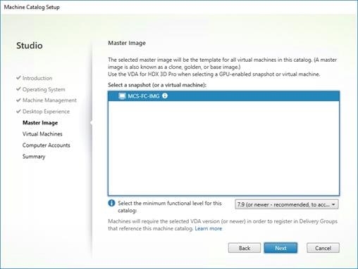
12. Specify the number of desktop to create and machine configuration.
13. Set amount of memory (MB) to be used by virtual desktops.
14. Select Full Copy for machine copy mode.
15. Click Next.
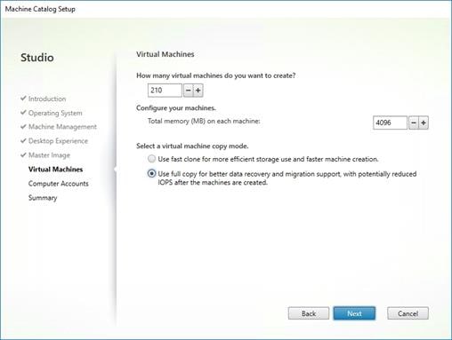
16. Specify AD account naming scheme and OU where accounts will be created.
17. Click Next.
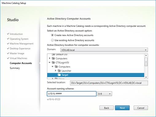
18. On Summary page specify Catalog name and click Finish to start deployment.
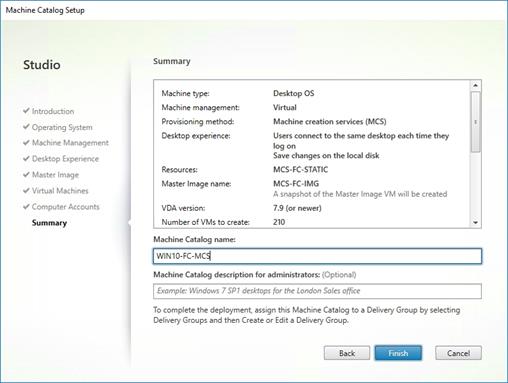
Delivery Groups are collections of machines that control access to desktops and applications. With Delivery Groups, you can specify which users and groups can access which desktops and applications.
To create delivery groups, follow these steps:
![]() The instructions below outline the procedure to create a Delivery Group for VDI desktops. When you have completed these steps, repeat the procedure to a Delivery Group for RDS desktops.
The instructions below outline the procedure to create a Delivery Group for VDI desktops. When you have completed these steps, repeat the procedure to a Delivery Group for RDS desktops.
1. Connect to a Citrix Virtual Apps & Desktops server and launch Citrix Studio.
2. Choose Create Delivery Group from the drop-down list.
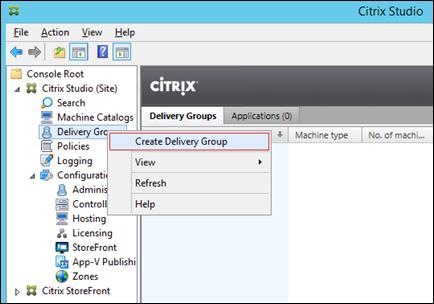
3. Click Next.
4. Specify the Machine Catalog and increment the number of machines to add.
5. Click Next.
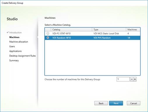
6. Specify what the machines in the catalog will deliver: Desktops, Desktops and Applications, or Applications.
7. Select Desktops.
8. Click Next.
9. To make the Delivery Group accessible, you must add users, select Allow any authenticated users to use this Delivery Group
![]() User assignment can be updated any time after Delivery group creation by accessing Delivery group properties in Desktop Studio.
User assignment can be updated any time after Delivery group creation by accessing Delivery group properties in Desktop Studio.
10. Click Next.
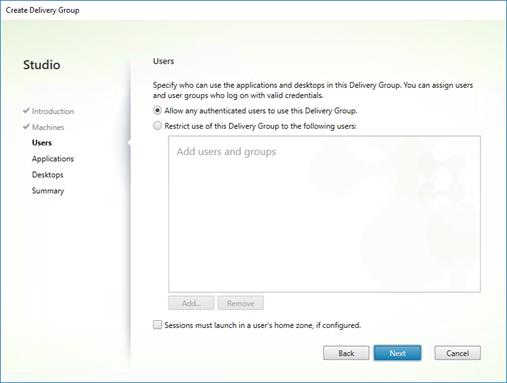
11. Click Next (no applications used in this design).
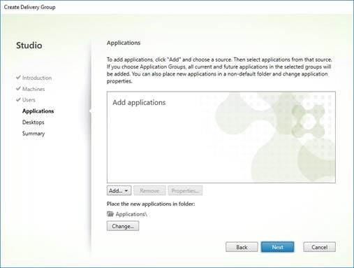
12. Enable Users to access the desktops.
13. Click Next.
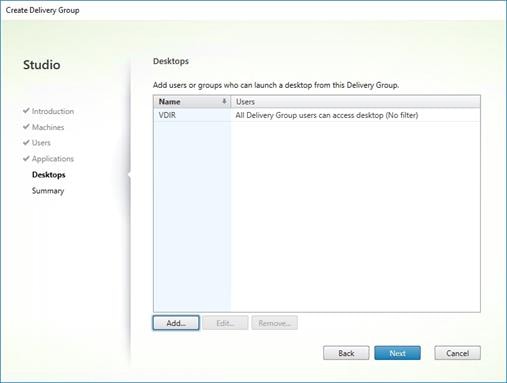
14. On the Summary dialog, review the configuration. Enter a Delivery Group name and a Description (Optional).
15. Click Finish.
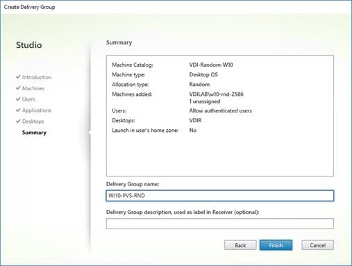
16. Citrix Studio lists the created Delivery Groups as well for the type, number of machines created, sessions, and applications for each group in the Delivery Groups tab.
17. From the drop-down list, select Turn on Maintenance Mode.
FSLogix for Citrix Virtual Apps & Desktops Profile Management
FSLogix for user profiles allows the Citrix Virtual Apps & Desktops environment to be easily and efficiently customized.
Configure FSLogix for Citrix Virtual Apps & Desktops Profiles Profile Container
Profile Container is a full remote profile solution for non-persistent environments. Profile Container redirects the entire user profile to a remote location. Profile Container configuration defines how and where the profile is redirected.
![]() Profile Container is inclusive of the benefits found in Office Container.
Profile Container is inclusive of the benefits found in Office Container.
When using Profile Container, both applications and users see the profile as if it's located on the local drive.
Before configuring Profile Container, follow these steps:
1. Verify that you meet all entitlement and configuration requirements.
2. Download and install FSLogix Software
3. Consider the storage and network requirements for your users' profiles (in this CVD, we used the Netapp A400 to store the FSLogix Profile disks).
4. Verify that your users have appropriate storage permissions where profiles will be placed.
5. Profile Container is installed and configured after stopping use of other solutions used to manage remote profiles.
6. Exclude the VHD(X) files for Profile Containers from Anti-Virus (AV) scanning.
Configure FSLogix Profile Management
To configure FSLogix profile management, follow these steps:
7. When the FSLogix software is downloaded, copy the ‘fslogix.admx and fslogix.adml’ to the ‘PolicyDefinitions’ folder in your domain to manage the settings with Group Policy.
8. On your VDI master image, install the FSLogix agent ‘FSLogixAppsSetup’ and accept all the defaults.
9. Create a Group Policy object and link it to the Organizational Unit the VDI computer accounts.
10. Right-click the FSLogix GPO policy.
11. Enable FSLogix Profile Management.
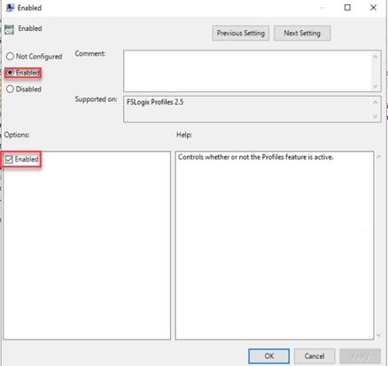
12. Select Profile Type (in this solution, we used Read-Write profiles).
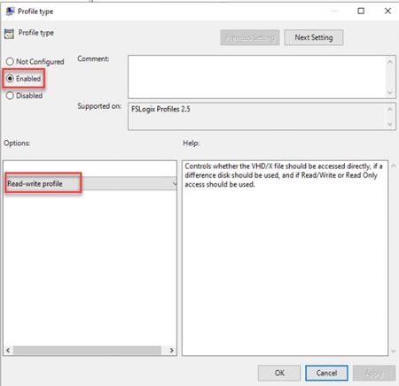
13. Enter the location of the Profile location (our solution used a CIFS share on the Netapp Array).
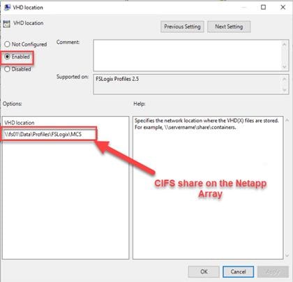
![]() We recommend using the Dynamic VHDX setting.
We recommend using the Dynamic VHDX setting.
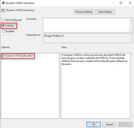
![]() VHDX is recommended over VHD.
VHDX is recommended over VHD.
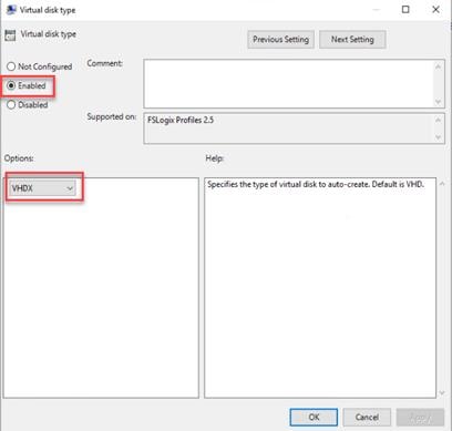
![]() We enabled the ‘Swap directory name components’ setting for an easier administration but is not necessary for improved performance.
We enabled the ‘Swap directory name components’ setting for an easier administration but is not necessary for improved performance.
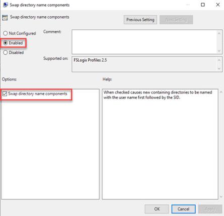
![]() FSLogix is an outstanding method of controlling the user experience and profile data in a VDI environment. There are many helpful settings and configurations for VDI with FSLogix that were not used in this solution.
FSLogix is an outstanding method of controlling the user experience and profile data in a VDI environment. There are many helpful settings and configurations for VDI with FSLogix that were not used in this solution.
In this solution, we tested a single UCS B200 M5 blade to validate against the performance of one blade and thirty B200 M5 blades across four chassis to illustrate linear scalability for each workload use case studied.
Cisco UCS Test Configuration for Single Blade Scalability
This test case validates Recommended Maximum Workload per host server using Citrix Virtual Apps & Desktops 1912 LTSR with 260 RDS sessions, 210 VDI Non-Persistent sessions, and 210 VDI Persistent sessions.
Figure 32. Test configuration for Single Server Scalability Citrix Virtual Apps & Desktops 1912 LTSR VDI (Persistent) Using MCS

Figure 33. Test configuration for Single Server Scalability Citrix Virtual Apps & Desktops 1912 LTSR VDI (Non-Persistent) using PVS
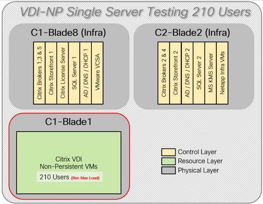
Figure 34. Test configuration for Single Server Scalability Citrix Virtual Apps & Desktops 1912 LTSR RDS
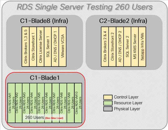
Hardware components:
● Cisco UCS 5108 Blade Server Chassis
● 2 Cisco UCS 6454 4th Gen Fabric Interconnects
● 2 (Infrastructure Hosts) Cisco UCS B200 M5 Blade servers with Intel Xeon Silver 4210 2.20-GHz 10-core processors, 384GB 2933MHz RAM for all host blades
● 1 (RDS/VDI Host) Cisco UCS B200 M5 Blade Servers with Intel Xeon Gold 6230 2.1-GHz 20-core processors, 768GB 2933MHz RAM for all host blades
● Cisco VIC 1440 CNA (1 per blade)
● 2 Cisco Nexus 93180YC-FX Access Switches
● 2 Cisco MDS 9132T 32-Gb 32-Port Fibre Channel Switches
● NetApp A400
Software components:
● Cisco UCS firmware 4.1(2b)
● Netapp ONTAP 9.7
● VMware ESXi 7.0 GA for host blades
● Citrix Virtual Apps & Desktops 1912 LTSR VDI Desktops and RDS Desktops
● FSLogix
● Microsoft SQL Server 2019
● Microsoft Windows 10 64 bit (2004), 2vCPU, 4 GB RAM, 40 GB HDD (master)
● Microsoft Windows Server 2019 (2004), 8vCPU, 32GB RAM, 60 GB vDisk (master)
● Microsoft Office 2016
● Login VSI 4.1.40 Knowledge Worker Workload (Benchmark Mode)
● NetApp Harvest, Graphite and Grafana
Cisco UCS Configuration for Full-Scale Testing
This test case validates thirty blade workloads using RDS/Citrix Virtual Apps & Desktops 1912 LTSR with 6000 RDS sessions, 5000 VDI Non-Persistent sessions, and 5000 VDI Persistent sessions. Server N+1 fault tolerance is factored into this solution for each workload and infrastructure cluster.
Figure 35. Full-Scale Test Configuration with 30 Blades
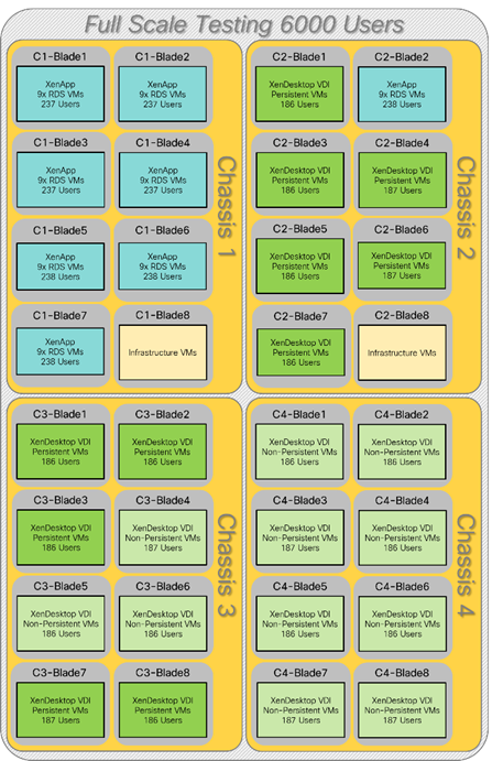
Hardware components:
● Cisco UCS 5108 Blade Server Chassis
● 2 Cisco UCS 6454 Fabric Interconnects
● 2 (Infrastructure Hosts) Cisco UCS B200 M4 Blade servers with Intel Xeon E5-2660v3 2.60-GHz 10-core processors, 128GB 2133MHz RAM for all host blades
● 30 (RDS/VDI Host) Cisco UCS B200 M5 Blade Servers with Intel Xeon Gold 6230 2.30-GHz 18-core processors, 768GB 2933MHz RAM for all host blades
● Cisco VIC 1440 CNA (1 per blade)
● 2 Cisco Nexus 93180YC-FX Access Switches
● 2 Cisco MDS 9132T Fibre Channel Storage Switches
● 1 NetApp AFF A400 storage system (2x storage controllers- Active/Active High Availability pair) with 2x DS224C disk shelves, 24x 3.8TB SSD- 65TB usable / 130TB effective (2:1 efficiency)
Software components:
● Cisco UCS firmware 4.1(2b)
● VMware ESXi 7.01 Update 1 for host blades
● Citrix RDS/Citrix Virtual Apps & Desktops 1912 LTSR VDI Hosted Virtual Desktops and RDS Hosted Shared Desktops
● Citrix Provisioning Server 1912 LTSR
● Citrix User Profile Manager
● Microsoft SQL Server 2016
● Microsoft Windows 10 64 bit, 2vCPU, 2 GB RAM, 32 GB vDisk (master)
● Microsoft Windows Server 2016, 9vCPU, 24GB RAM, 40 GB vDisk (master)
● Microsoft Office 2016
● Login VSI 4.1.25 Knowledge Worker Workload (Benchmark Mode)
Testing Methodology and Success Criteria
All validation testing was conducted on-site within the Cisco labs in San Jose, California.
The testing results focused on the entire process of the virtual desktop lifecycle by capturing metrics during the desktop boot-up, user logon and virtual desktop acquisition (also referred to as ramp-up,) user workload execution (also referred to as steady state), and user logoff for the Citrix RDS and Citrix Virtual Apps & Desktops Hosted Virtual Desktop and RDS Hosted Shared models under test.
Test metrics were gathered from the hypervisor, virtual desktop, storage, and load generation software to assess the overall success of an individual test cycle. Each test cycle was not considered passing unless all of the planned test users completed the ramp-up and steady state phases (described below) and unless all metrics were within the permissible thresholds as noted as success criteria.
Three successfully completed test cycles were conducted for each hardware configuration and results were found to be relatively consistent from one test to the next.
You can obtain additional information and a free test license from http://www.loginvsi.com.
The following protocol was used for each test cycle in this study to ensure consistent results.
Pre-Test Setup for Single and Multi-Blade Testing
All virtual machines were shut down utilizing the Citrix Virtual Apps & Desktops Administrator and vCenter.
All Launchers for the test were shut down. They were then restarted in groups of 10 each minute until the required number of launchers was running with the Login VSI Agent at a “waiting for test to start” state.
All VMware ESXi VDI host blades to be tested were restarted prior to each test cycle.
Test Run Protocol
To simulate severe, real-world environments, Cisco requires the log-on and start-work sequence, known as Ramp Up, to complete in 48 minutes. Additionally, we require all sessions started, whether single server users or full-scale test users to become active within two minutes after the last session is launched.
In addition, Cisco requires that the Login VSI Benchmark method is used for all single server and scale testing. This assures that our tests represent real-world scenarios. For each of the three consecutive runs on single server tests, the same process was followed. Follow these steps:
1. Time 0:00:00 Start PerfMon/Esxtop/XenServer Logging on the following systems:
a. Infrastructure and VDI Host Blades used in the test run
b. SCVMM/vCenter used in the test run
c. All Infrastructure VMs used in test run (AD, SQL, brokers, image mgmt., and so on)
2. Time 0:00:10 Start Storage Partner Performance Logging on Storage System
3. Time 0:05: Boot Virtual Desktops/RDS Virtual Machines using Citrix Virtual Apps & Desktops Studio or View Connection server.
![]() The boot rate should be around 10-12 VMs per minute per server.
The boot rate should be around 10-12 VMs per minute per server.
4. Time 0:06 First machines boot
5. Time 0:30 Single Server or Scale target number of desktop VMs booted on 1 or more blades
![]() No more than 30 minutes for boot up of all virtual desktops is allowed.
No more than 30 minutes for boot up of all virtual desktops is allowed.
6. Time 0:35 Single Server or Scale target number of desktop VMs desktops registered on XD Studio or available on View Connection Server
7. Virtual machine settling time.
![]() No more than 60 Minutes of rest time is allowed after the last desktop is registered on the XD Studio or available in View Connection Server dashboard. Typically, a 30-40 minute rest period is sufficient.
No more than 60 Minutes of rest time is allowed after the last desktop is registered on the XD Studio or available in View Connection Server dashboard. Typically, a 30-40 minute rest period is sufficient.
8. Time 1:35 Start Login VSI 4.1.40 Office Worker Benchmark Mode Test, setting auto-logoff time at 900 seconds, with Single Server or Scale target number of desktop VMs utilizing sufficient number of Launchers (at 20-25 sessions/Launcher)
9. Time 2:23 Single Server or Scale target number of desktop VMs desktops launched (48 minute benchmark launch rate)
10. Time 2:25 All launched sessions must become active
![]() All sessions launched must become active for a valid test run within this window.
All sessions launched must become active for a valid test run within this window.
11. Time 2:40 Login VSI Test Ends (based on Auto Logoff 900 Second period designated above.)
12. Time 2:55 All active sessions logged off
13. Time 2:57 All logging terminated; Test complete
14. Time 3:15 Copy all log files off to archive; Set virtual desktops to maintenance mode through broker; Shutdown all Windows machines
15. Time 3:30 Reboot all hypervisor hosts.
16. Time 3:45 Ready for the new test sequence.
Our “pass” criteria for this testing follows:
Cisco will run tests at a session count level that effectively utilizes the blade capacity measured by CPU utilization, memory utilization, storage utilization, and network utilization. We will use Login VSI to launch version 4.1 Office Worker workloads. The number of launched sessions must equal active sessions within two minutes of the last session launched in a test as observed on the VSI Management console.
The Citrix Desktop Studio be monitored throughout the steady state to make sure of the following:
● All running sessions report In Use throughout the steady state
● No sessions move to unregistered, unavailable or available state at any time during steady state
Within 20 minutes of the end of the test, all sessions on all launchers must have logged out automatically and the Login VSI Agent must have shut down. Stuck sessions define a test failure condition.
Cisco requires three consecutive runs with results within +/-1% variability to pass the Cisco Validated Design performance criteria. For white papers written by partners, two consecutive runs within +/-1% variability are accepted. (All test data from partner run testing must be supplied along with the proposed white paper.)
We will publish Cisco Validated Designs with our recommended workload following the process above and will note that we did not reach a VSImax dynamic in our testing. FlexPod Data Center with Cisco UCS and Citrix RDS/Citrix Virtual Apps & Desktops 1912 LTSR on VMware ESXi 7.01 Update 1 Test Results
The purpose of this testing is to provide the data needed to validate Citrix RDS Hosted Shared Desktop (RDS) and Citrix Virtual Apps & Desktops Hosted Virtual Desktop (VDI) randomly assigned, non-persistent with Citrix Provisioning Services 1912 LTSR and Citrix Virtual Apps & Desktops Hosted Virtual Desktop (VDI) statically assigned, persistent full-clones models using ESXi and vCenter to virtualize Microsoft Windows 10 desktops and Microsoft Windows Server 2019 sessions on Cisco UCS B200 M5 Blade Servers using a NetApp AFF400 storage system.
The information contained in this section provides data points that a customer may reference in designing their own implementations. These validation results are an example of what is possible under the specific environment conditions outlined here, and do not represent the full characterization of Citrix products with VMware vSphere.
Four test sequences, each containing three consecutive test runs generating the same result, were performed to establish single blade performance and multi-blade, linear scalability.
The philosophy behind Login VSI is different from conventional benchmarks. In general, most system benchmarks are steady state benchmarks. These benchmarks execute one or multiple processes, and the measured execution time is the outcome of the test. Simply put: the faster the execution time or the bigger the throughput, the faster the system is according to the benchmark.
Login VSI is different in approach. Login VSI is not primarily designed to be a steady state benchmark (however, if needed, Login VSI can act like one). Login VSI was designed to perform benchmarks for SBC or VDI workloads through system saturation. Login VSI loads the system with simulated user workloads using well known desktop applications like Microsoft Office, Internet Explorer, and Adobe PDF reader. By gradually increasing the amount of simulated users, the system will eventually be saturated. Once the system is saturated, the response time of the applications will increase significantly. This latency in application response times show a clear indication whether the system is (close to being) overloaded. As a result, by nearly overloading a system it is possible to find out what its true maximum user capacity is.
After a test is performed, the response times can be analyzed to calculate the maximum active session/desktop capacity. Within Login VSI this is calculated as VSImax. When the system is coming closer to its saturation point, response times will rise. When reviewing the average response time, it will be clear the response times escalate at saturation point.
This VSImax is the “Virtual Session Index (VSI)”. With Virtual Desktop Infrastructure (VDI) and Terminal Services (RDS) workloads this is valid and useful information. This index simplifies comparisons and makes it possible to understand the true impact of configuration changes on hypervisor host or guest level.
Server-Side Response Time Measurements
It is important to understand why specific Login VSI design choices have been made. An important design choice is to execute the workload directly on the target system within the session instead of using remote sessions. The scripts simulating the workloads are performed by an engine that executes workload scripts on every target system and are initiated at logon within the simulated user’s desktop session context.
An alternative to the Login VSI method would be to generate user actions client side through the remoting protocol. These methods are always specific to a product and vendor dependent. More importantly, some protocols simply do not have a method to script user actions client side.
For Login VSI the choice has been made to execute the scripts completely server side. This is the only practical and platform independent solution, for a benchmark like Login VSI.
Calculate VSImax v4.1.x
The simulated desktop workload is scripted in a 48 minute loop when a simulated Login VSI user is logged on, performing generic Office worker activities. After the loop is finished it will restart automatically. Within each loop, the response times of sixteen specific operations are measured in a regular interval: sixteen times in within each loop. The response times of these five operations are used to determine VSImax.
The five operations from which the response times are measured are:
● Notepad File Open (NFO)
Loading and initiating VSINotepad.exe and opening the openfile dialog. This operation is handled by the OS and by the VSINotepad.exe itself through execution. This operation seems almost instant from an end-user’s point of view.
● Notepad Start Load (NSLD)
Loading and initiating VSINotepad.exe and opening a file. This operation is also handled by the OS and by the VSINotepad.exe itself through execution. This operation seems almost instant from an end-user’s point of view.
● Zip High Compression (ZHC)
This action copy's a random file and compresses it (with 7zip) with high compression enabled. The compression will very briefly spike CPU and disk IO.
● Zip Low Compression (ZLC)
This action copy's a random file and compresses it (with 7zip) with low compression enabled. The compression will very briefly disk IO and creates some load on the CPU.
● CPU
Calculates a large array of random data and spikes the CPU for a short period of time.
These measured operations within Login VSI do hit considerably different subsystems such as CPU (user and kernel), Memory, Disk, the OS in general, the application itself, print, GDI, etc. These operations are specifically short by nature. When such operations become consistently long: the system is saturated because of excessive queuing on any kind of resource. As a result, the average response times will then escalate. This effect is clearly visible to end-users. If such operations consistently consume multiple seconds the user will regard the system as slow and unresponsive.
Figure 36. Sample of a VSI max response time graph, representing a normal test

Figure 37. Sample of a VSI test response time graph where there was a clear performance issue

When the test is finished, VSImax can be calculated. When the system is not saturated, and it could complete the full test without exceeding the average response time latency threshold, VSImax is not reached and the amount of sessions ran successfully.
The response times are very different per measurement type, for instance Zip with compression can be around 2800 ms, while the Zip action without compression can only take 75ms. These response time of these actions are weighted before they are added to the total. This ensures that each activity has an equal impact on the total response time.
In comparison to previous VSImax models, this weighting much better represents system performance. All actions have very similar weight in the VSImax total. The following weighting of the response times is applied.
The following actions are part of the VSImax v4.1 calculation and are weighted as follows (US notation):
● Notepad File Open (NFO): 0.75
● Notepad Start Load (NSLD): 0.2
● Zip High Compression (ZHC): 0.125
● Zip Low Compression (ZLC): 0.2
● CPU: 0.75
This weighting is applied on the baseline and normal Login VSI response times.
With the introduction of Login VSI 4.1, we also created a new method to calculate the basephase of an environment. With the new workloads (Taskworker, Powerworker, and so on) enabling 'basephase' for a more reliable baseline has become obsolete. The calculation is explained below. In total 15 lowest VSI response time samples are taken from the entire test; the lowest 2 samples are removed, and the 13 remaining samples are averaged. The result is the Baseline. To calculate the basephase, follow these steps:
1. Take the lowest 15 samples of the complete test
2. From those 15 samples remove the lowest 2
3. Average the 13 results that are left is the baseline
The VSImax average response time in Login VSI 4.1.x is calculated on the amount of active users that are logged on the system.
Always a 5 Login VSI response time samples are averaged + 40 percent of the number of “active” sessions. For example, if the active sessions is 60, then latest 5 + 24 (=40 percent of 60) = 31 response time measurement are used for the average calculation.
To remove noise (accidental spikes) from the calculation, the top 5 percent, and bottom 5 percent of the VSI response time samples are removed from the average calculation, with a minimum of 1 top and 1 bottom sample. As a result, with 60 active users, the last 31 VSI response time sample are taken. From those 31 samples the top 2 samples are removed and lowest 2 results are removed (5 percent of 31 = 1.55, rounded to 2). At 60 users the average is then calculated over the 27 remaining results.
VSImax v4.1.x is reached when the VSIbase + a 1000 ms latency threshold is not reached by the average VSI response time result. Depending on the tested system, VSImax response time can grow 2 - 3x the baseline average. In end-user computing, a 3x increase in response time in comparison to the baseline is typically regarded for the maximum performance degradation to be considered acceptable.
In VSImax v4.1.x this latency threshold is fixed to 1000ms, this allows better and fairer comparisons between two different systems, especially when they have different baseline results. Ultimately, in VSImax v4.1.x, the performance of the system is not decided by the total average response time, but by the latency is has under load. For all systems, this is now 1000ms (weighted).
The threshold for the total response time is: average weighted baseline response time + 1000ms.
When the system has a weighted baseline response time average of 1500ms, the maximum average response time may not be greater than 2500ms (1500+1000). If the average baseline is 4000 the maximum average response time may not be greater than 4000ms (4000+1000).
When the threshold is not exceeded by the average VSI response time during the test, VSImax is not hit and the amount of sessions ran successfully. This approach is fundamentally different in comparison to previous VSImax methods, as it was always required to saturate the system beyond VSImax threshold.
Lastly, VSImax v4.1.x is now always reported with the average baseline VSI response time result. For example: “The VSImax v4.1 was 125 with a baseline of 1526ms”. This helps considerably in the comparison of systems and gives a more complete understanding of the system. The baseline performance helps to understand the best performance the system can give to an individual user. VSImax indicates what the total user capacity is for the system. These two are not automatically connected and related:
When a server with a very fast dual core CPU, running at 3.6 GHz, is compared to a 10 core CPU, running at 2,26 GHz, the dual core machine will give and individual user better performance than the 10 core machine. This is indicated by the baseline VSI response time. The lower this score is, the better performance an individual user can expect.
However, the server with the slower 10 core CPU will easily have a larger capacity than the faster dual core system. This is indicated by VSImax v4.1.x, and the higher VSImax is, the larger overall user capacity can be expected.
With Login VSI 4.1.x a new VSImax method is introduced: VSImax v4.1. This methodology gives much better insight into system performance and scales to extremely large systems.
Single-Server Recommended Maximum Workload
For both the Citrix Virtual Apps & Desktops 1912 LTSR Hosted Virtual Desktop and Citrix RDS 1912 LTSR RDS Hosted Shared Desktop use cases, a recommended maximum workload was determined by the Login VSI Knowledge Worker Workload in VSI Benchmark Mode end user experience measurements and blade server operating parameters.
This recommended maximum workload approach allows you to determine the server N+1 fault tolerance load the blade can successfully support in the event of a server outage for maintenance or upgrade.
Our recommendation is that the Login VSI Average Response and VSI Index Average should not exceed the Baseline plus 2000 milliseconds to insure that end user experience is outstanding. Additionally, during steady state, the processor utilization should average no more than 90-95%. (Memory should never be oversubscribed for Desktop Virtualization workloads.)
Table 19. Phases of test runs
| Test Phase |
Description |
| Boot |
Start all RDS and VDI virtual machines at the same time |
| Idle |
The rest time after the last desktop is registered on the XD Studio. (typically, a 30-40 minute, <60 min) |
| Logon |
The Login VSI phase of the test is where sessions are launched and start executing the workload over a 48 minutes duration |
| Steady state |
The steady state phase is where all users are logged in and performing various workload tasks such as using Microsoft Office, Web browsing, PDF printing, playing videos, and compressing files (typically for 15-minute duration) |
| Logoff |
Session’s finish executing the Login VSI workload and logoff |
Single-Server Recommended Maximum Workload Testing
This section shows the key performance metrics that were captured on the Cisco UCS host blades during the single server testing to determine the Recommended Maximum Workload per host server. The single server testing comprised of three tests: 260 RDS sessions, 210 VDI Non-Persistent sessions, and 210 VDI Persistent sessions.
Single-Server Recommended Maximum Workload for RDS with 260 Users
The following figure illustrates the single-server recommended maximum workload for RDS with 260 users.
Figure 38. Single Server Recommended Maximum Workload for RDS with 260 Users

The recommended maximum workload for a Cisco UCS B200 M5 blade server with dual Intel Xeon Gold 6230 processors, 768GB 2933MHz RAM is 260 Server 2019 Hosted Shared Desktops. Each dedicated blade server ran 10 Server 2019 Virtual Machines. Each virtual server was configured with 8 vCPUs and 32GB RAM.
Figure 39. Single Server Recommended Maximum Workload | RDS 1912 LTSR RDS | VSI Score
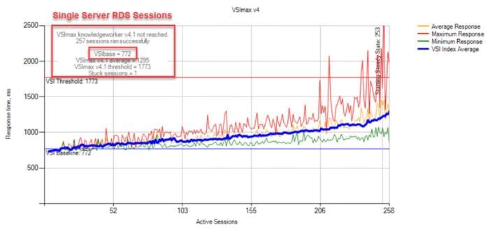
Figure 40. Single Server Recommended Maximum Workload | RDS 1912 LTSR RDS | VSI Repeatability
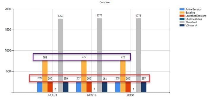
Performance data for the server running the workload is as follows:
Figure 41. Single Server Recommended Maximum Workload | RDS 1912 LTSRRDS | Host CPU Utilization

Figure 42. Single Server Recommended Maximum Workload | RDS 1912 LTSRRDS | Host Memory Utilization
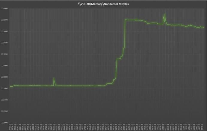
Figure 43. Single Server | RDS 1912 LTSRRDS | Host Network Utilization
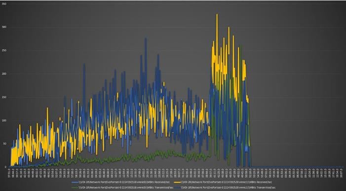
Single-Server Recommended Maximum Workload for VDI Non-Persistent with 210 Users
The following figure illustrates the single-server recommended maximum workload for VDI non-persistent with 210 users.
Figure 44. Single Server Recommended Maximum Workload for VDI Non-Persistent with 210 Users

The recommended maximum workload for a Cisco UCS B200 M5 blade server with dual Intel Xeon Gold 6230 processors, 768GB 2933MHz RAM is 210 Windows 10 64-bit virtual machines with 2 vCPU and 4GB RAM. Login VSI and blade performance data as follows:
Figure 45. Single Server | Citrix Virtual Apps & Desktops 1912 LTSR VDI-NP | VSI Score
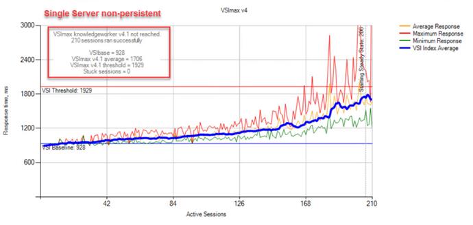
Figure 46. Single Server | Citrix Virtual Apps & Desktops 1912 LTSR VDI-NP | VSI Repeatability
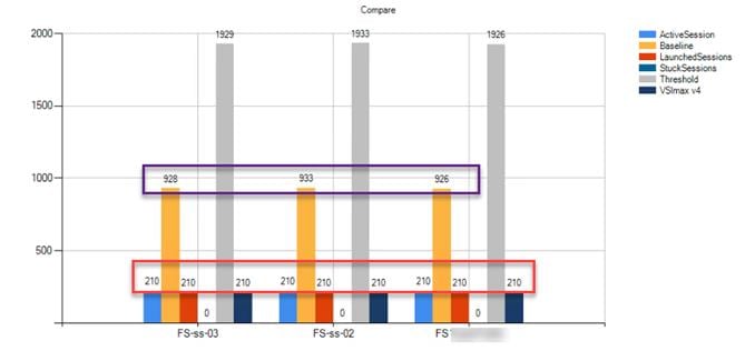
Performance data for the server running the workload is as follows:
Figure 47. Single Server | Citrix Virtual Apps & Desktops 1912 LTSR VDI-NP | Host CPU Utilization
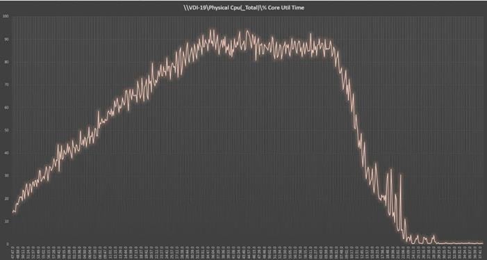
Figure 48. Single Server | Citrix Virtual Apps & Desktops 1912 LTSR VDI-NP | Host Memory Utilization
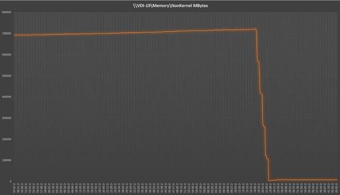
Figure 49. Single Server | Citrix Virtual Apps & Desktops 1912 LTSR VDI-NP | Host Network Utilization
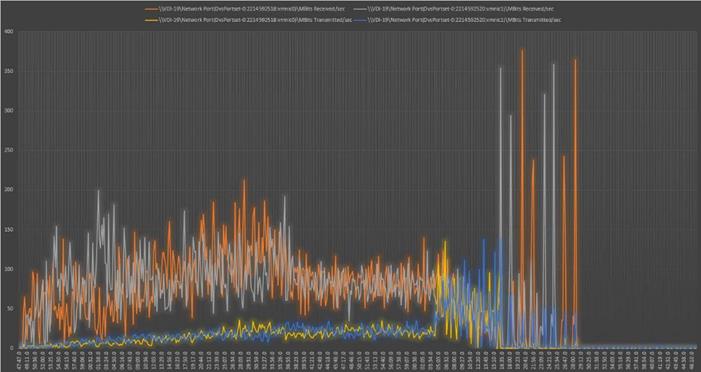
Single-Server Recommended Maximum Workload for VDI Persistent with 210 Users
Figure 50 illustrates the single-server recommended maximum workload for VDI persistent with 210 users.
Figure 50. Single Server Recommended Maximum Workload for VDI Persistent with 210 Users
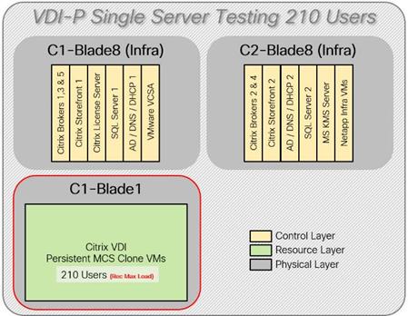
The recommended maximum workload for a B200 M5 blade server with dual Intel Xeon Gold 6230 processors, 768GB 2933MHz RAM is 210 Windows 10 64-bit virtual machines with 2 vCPU and 4GB RAM. Login VSI and blade performance data is as follows:
Figure 51. Single Server | Citrix Virtual Apps & Desktops 1912 LTSR VDI-P | VSI Score

Figure 52. Single Server | Citrix Virtual Apps & Desktops 1912 LTSR VDI-P | VSI Repeatability
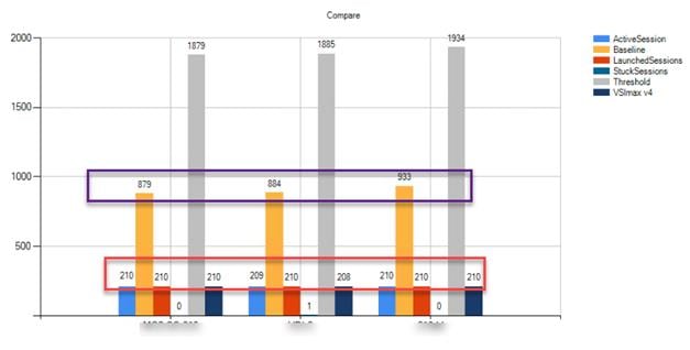
Performance data for the server running the workload is as follows:
Figure 53. Single Server | Citrix Virtual Apps & Desktops 1912 LTSR VDI-P | Host CPU Utilization
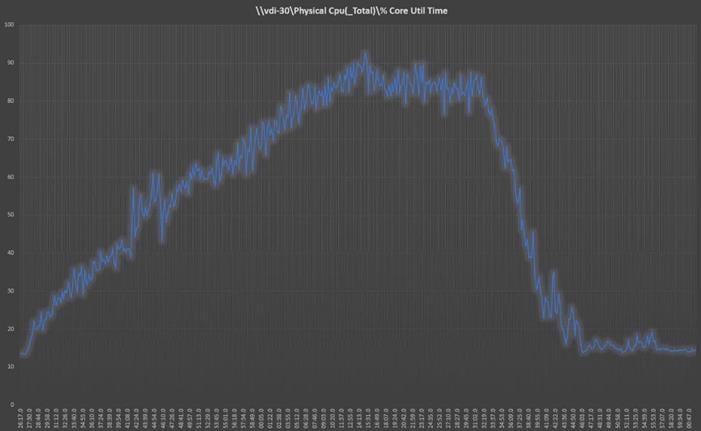
Figure 54. Single Server | Citrix Virtual Apps & Desktops 1912 LTSR VDI-P | Host Memory Utilization

Figure 55. Single Server | Citrix Virtual Apps & Desktops 1912 LTSR VDI-P | Host Network Utilization
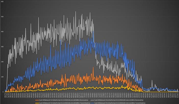
Full-Scale RDS Workload Testing with 6000 Users
This section shows the key performance metrics that were captured on the Cisco UCS, during the full-scale testing. The full-scale testing with 6000 users comprised of: 6000 Hosted Shared Desktop Sessions using 30 blades,.
To achieve the target, sessions were launched against all workload clusters concurrently. As per the Cisco Test Protocol for VDI solutions, all sessions were launched within 48 minutes (using the official Knowledge Worker Workload in VSI Benchmark Mode) and all launched sessions became active within two minutes subsequent to the last logged in session.
The configured system efficiently and effectively delivered the following results:
Figure 56. Full-Scale | 6000 Mixed Users | VSI Score
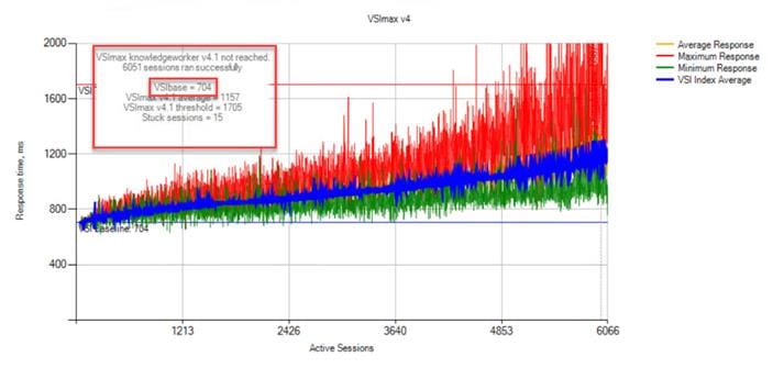
Figure 57. Full-Scale | 6000 Mixed Users | VSI Repeatability
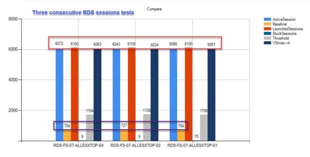
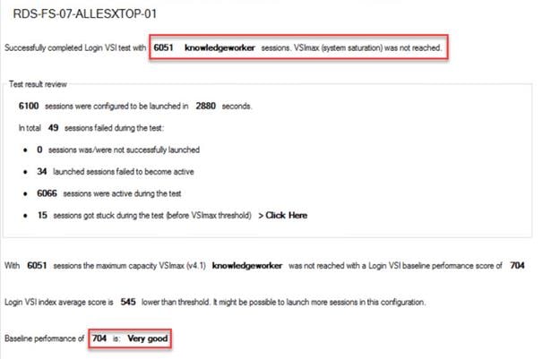
Figure 58. Full-Scale | 6000 RDS Users | RDS Hosts | Host CPU Utilization

Figure 59. Full-Scale | 6000 RDS Users | RDS Hosts | Host Memory Utilization
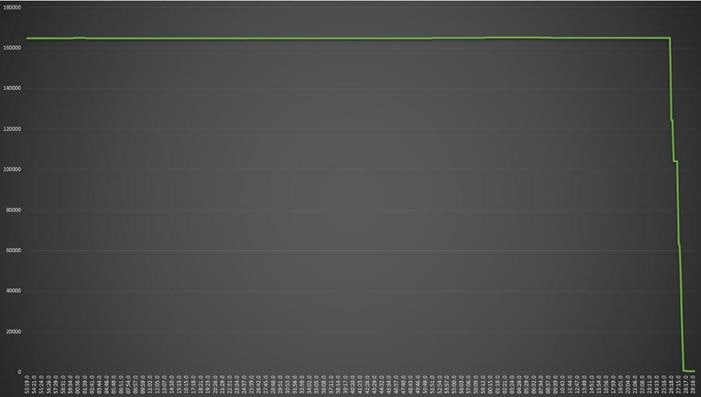
Figure 60. Full-Scale | 6000 RDS Users | RDS Hosts | Host Network Utilization
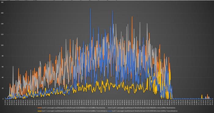
Full-Scale Non-Persistent Workload Testing with 5000 Users
This section shows the key performance metrics that were captured on the Cisco UCS, during the full-scale testing. The full-scale testing with 5000 users comprised of: 5000 Hosted Virtual Desktops using 30 blades.
The combined mixed workload for the solution is 5000 users. To achieve the target, sessions were launched against all workload clusters concurrently. As per the Cisco Test Protocol for VDI solutions, all sessions were launched within 48 minutes (using the official Knowledge Worker Workload in VSI Benchmark Mode) and all launched sessions became active within two minutes subsequent to the last logged in session.
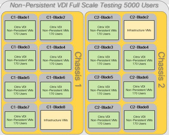
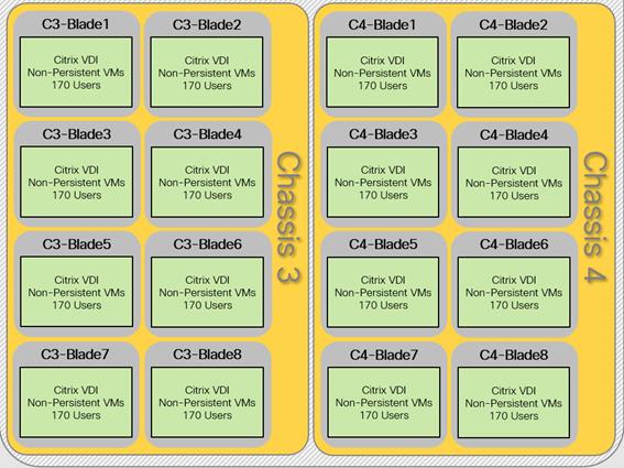
The configured system efficiently and effectively delivered the following results:
Figure 61. Full-Scale | 5000 non-persistent Users | VSI Score
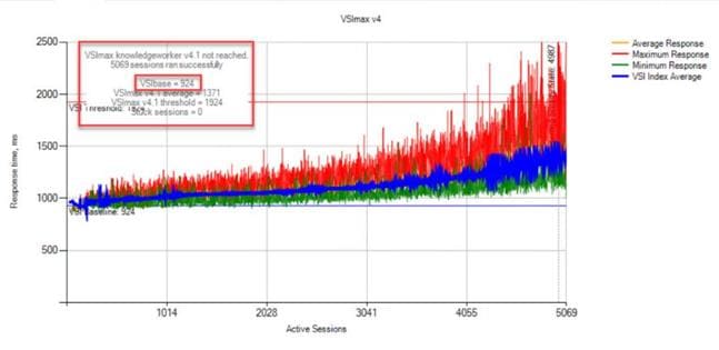
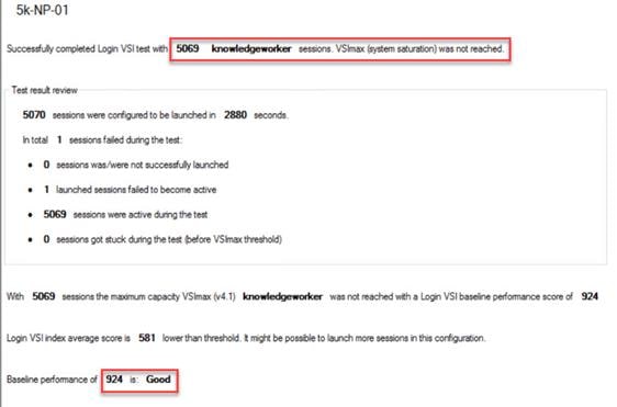
Figure 62. Full-Scale | 5000 Non-persistent Users | VSI Repeatability
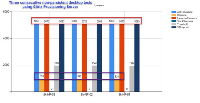
Figure 63. Full-Scale | 5000 non-persistent Users | NP-VDI Hosts | Host CPU Utilization

Figure 64. Full-Scale | 5000 non-persistent users | NP-VDI Hosts | Host Memory Utilization
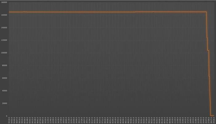
Figure 65. Full-Scale | 5000 non-persistent users | NP-VDI Hosts | Host Network Utilization
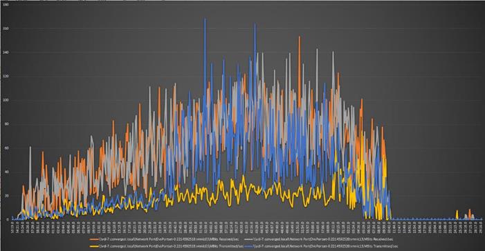
Full-Scale Persistent Workload Testing with 5000 Users
This section shows the key performance metrics that were captured on the Cisco UCS, during the full-scale testing. The full-scale testing with 5000 users comprised of: 5000 Persistent Hosted Virtual Desktop using 30 blades.
The combined mixed workload for the solution is 5000 users. To achieve the target, sessions were launched against all workload clusters concurrently. As per the Cisco Test Protocol for VDI solutions, all sessions were launched within 48 minutes (using the official Knowledge Worker Workload in VSI Benchmark Mode) and all launched sessions became active within two minutes subsequent to the last logged in session.
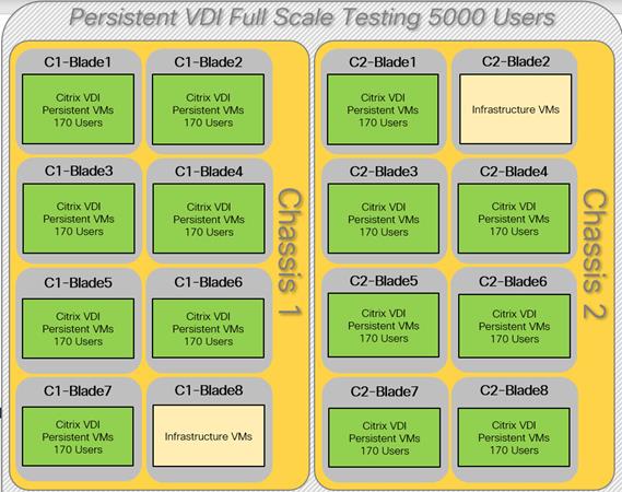
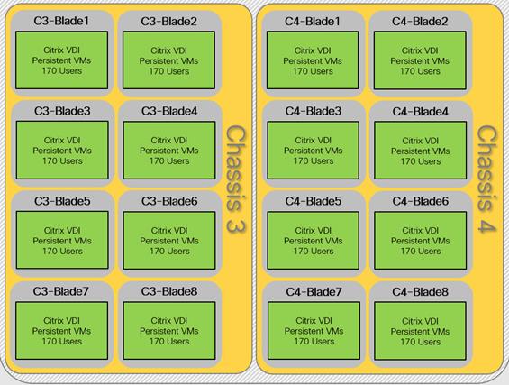
The configured system efficiently and effectively delivered the following results.:
Figure 66. Full-Scale | 6000 Mixed Users | VSI Score
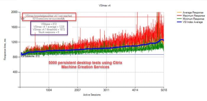
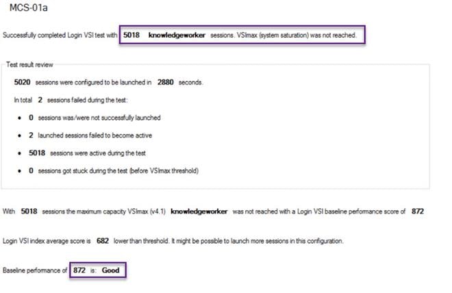
Figure 67. Full-Scale | 6000 Mixed Users | VSI Repeatability
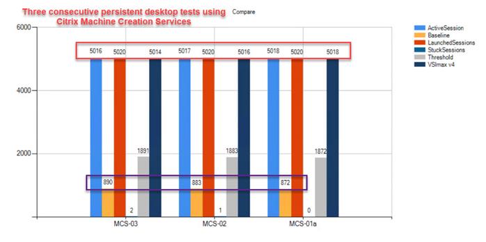
Figure 68. Full-Scale | 5000 persistent users | P-VDI Hosts | Host CPU Utilization
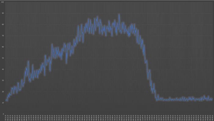
Figure 69. Full-Scale | 5000 persistent users | P-VDI Hosts | Host Memory Utilization

Figure 70. Full-Scale | 5000 persistent users | P-VDI Hosts | Host Network Utilization
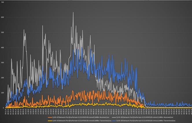
AFF A400 Storage Detailed Test Results for Cluster Scalability Test
This section highlights and provides analysis of the NetApp AFF A400 storage system performance results for each of the Citrix software module testing (HSD, PVS, Persistent), which we call cluster testing, and they are identified previously in this document. Specifically, it depicts and discusses the results for the following test case scenarios:
● 1900 Windows Server 2016 Citrix Hosted Shared desktops (RDS)
● 2100 Windows 10 x64 Citrix PVS Non-Persistent desktops
● 2100 Windows 10 x64 Citrix Persistent Full-Clone desktops
From a storage perspective, it is critical to maintain a latency of less than a millisecond for an optimal end-user experience no matter the IOPS and bandwidth being driven. The test results indicate that the AFF A400 storage delivers that essential minimum level of latency despite driving a substantial amount of IOPs and bandwidth for the thousands of desktops hosted on the AFF A400 system.
The sections that follow show screenshots of the AFF A400 storage test data for all three use case scenarios with information about IOPS, bandwidth, and latency at the peak of each use case test. In all three use cases (cluster level testing with HSD PVS VDI, full clone persistent desktops and full-scale mixed workload sessions, the criteria followed prior to launching Login VSI workload test are the same.
6000 Users Citrix HSD (RDS) Windows 2019 Sessions
This test uses Login VSI for the workload generator in Benchmark mode with the Knowledge Worker user type and with Citrix Hosted Shared Desktops (RDSH) Sessions for the VDI delivery mechanism. This first highlighted cluster test shows that the AFF A400 can easily handle this workload with exceptional end-user experience as confirmed from Login VSI.
6000 Citrix HSD (RDS) Cluster Test: Storage Charts
SVM Performance
From the charts below, we notice that Read:Write is around 1:4 for the SVM, Max IOPS is about 10000 IOPS and read/write latency is very low which produces better response time for the users.
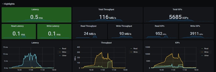
NFSv3
NFS protocol is used by Virtual machines hosting the server sessions. It’s peak IOPS is around 4000 and workload is write heavy compared to read operations. The average latency stayed below 1ms.
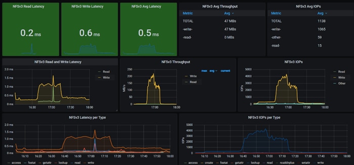
NFS Logical Interface
We notice both the network interfaces are equally utilized and the load is distributed to both storage nodes.
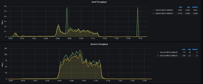
SMB
The file share is used for storing user profile containers with FSLogix. The Write IOPS is around 6000 during session launch and it reached peak of around 8000 IOPS during session logoff.
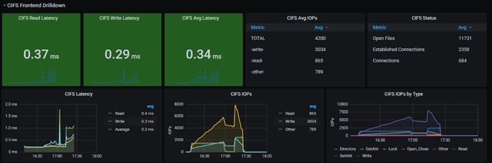
SMB Logical Interface
Here we notice both the network interfaces are equally utilized. ONTAP does support SMB3 multi-session. Even though, in this test, we just used single NIC on virtual desktops.
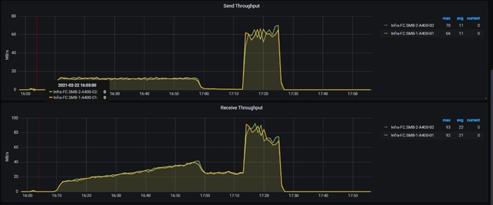
Storage Node Ethernet Port Throughput
Even though the logical ports are equally utilized, we notice there is performance difference between port e0f and e0g on storage node 02. You will need to double-check the LACP configuration on the physical switches.
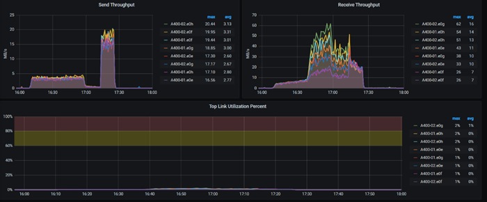
FlexGroup IOPS
For this test case, we noticed SMB file storage is demanding more IOPS compared to block on NFS.
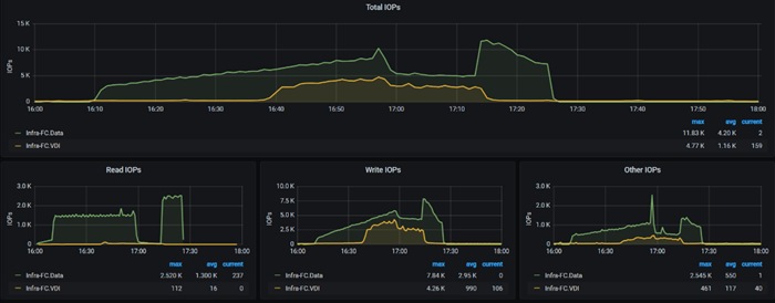
FlexGroup Member Volume IOPS
The IO pattern on constituent member volume matches close to IO pattern of FlexGroup.
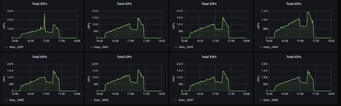
FlexGroup Latency and bandwidth
The disk latency is low (which is the desired state) for this test case. The networks are underutilized and has more headroom to add other workloads.
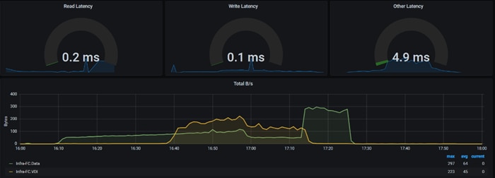
Node A400-01 Latency & CPU Utilization
For this use case, CPU on storage nodes are well below 25% and can be treated as underutilized.

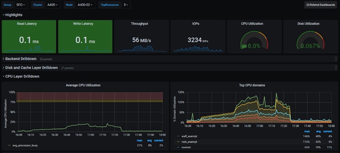
5000 Users Persistent Desktops Cluster Test
NetApp AFF A400 Test Results for 5000 Persistent Windows 10 x64 Citrix MCS Desktops
SVM Performance
For this use case, SVM noticed IOPS of around 40000 while Read/Write latency below is way below 1ms. Read/Write ratio is around 1:6.
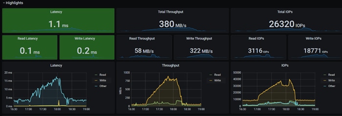
NFSv3
We noticed about 40000 IOPS is consumed by 5000 virtual desktops for write operations which is around 6 IOPS per desktop. The network throughput is around 750MB/s during peak session count. The average latency is 0.5ms.
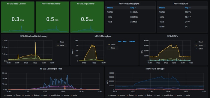
The NFS logical network interfaces are utilized equally.
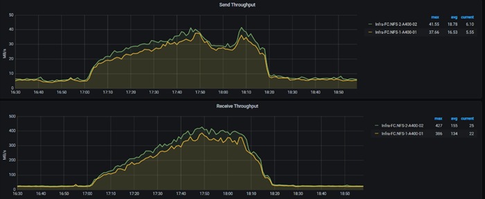
SMB
For this use case, SMB noticed a peak IOPS of around 6000 when users starting to logoff.
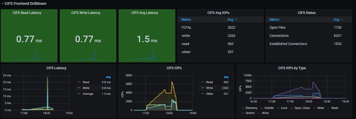
The logical network interfaces are equally utilized. Each logical network interface is hosted on every storage node. The physical port e0f and e0g on storage node 02 showing difference in performance for this test case too.
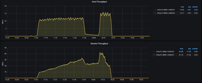
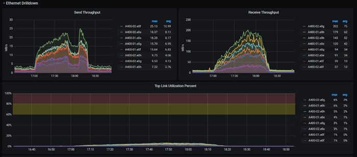
FlexGroup IOPS
On this use case, we are seeing VDI datastore is consumed more than SMB file share. SMB file share is used most when users are logging off.
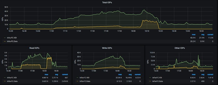
FlexGroup Latency and Bandwidth
For the number of virtual desktops on VDI datastore puts into use, we can see the disk bandwidth is consumed and it was at peak of around 880 KB/s.
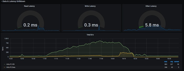
FlexGroup Member Volumes
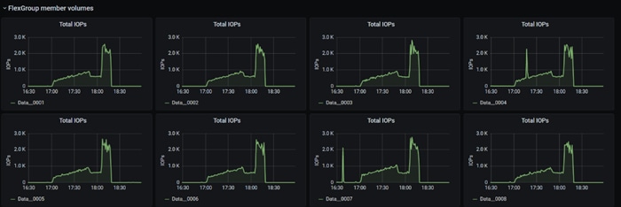
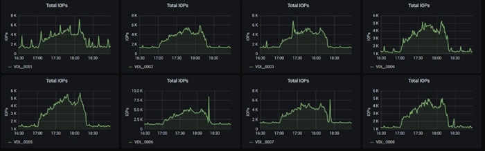
Storage Node
The CPU utilization of storage nodes reached a max of around 80% which is ideal. If planning to add other workloads in to this cluster, you will need to consider adding storage nodes.
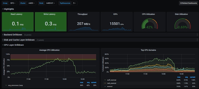
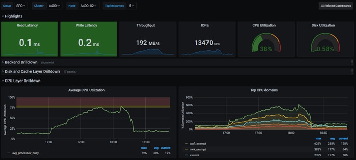
5000 Users PVS Non-Persistent Desktops Cluster Test
NetApp
SVM
In this use case, we noticed the write IOPS at peak of 14000 at SVM during logoff process. The read/write ratio is about 1:6. Read/write latency stayed below 1ms and peak throughput is around 400MB/s.
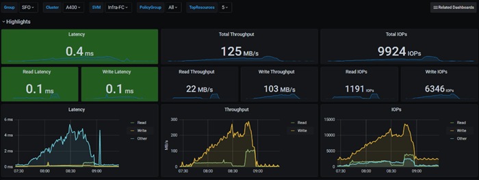
NFSv3
With PVS, the desktop image is retrieved from SMB share, then uses compute resources & SMB share for user profiles. The reason we are seeing activity with NFS is, we distributed infrastructure VMs across FC datastore and NFS datastore. Even though the NFS datastore is different, it used the logical network interfaces since we had single SVM. To avoid this scenario, need to have separate SVM for Infrastructure and workloads like how the compute resources are separated out.
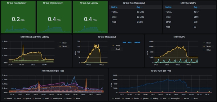
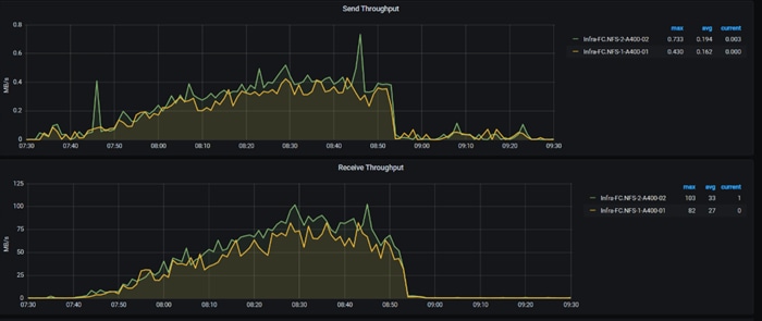
SMB
For this use case, SMB is used for streaming vDisks and for storing user profile containers. Compared to MCS, we can notice SMB network throughput is 1-2 MB/s higher.
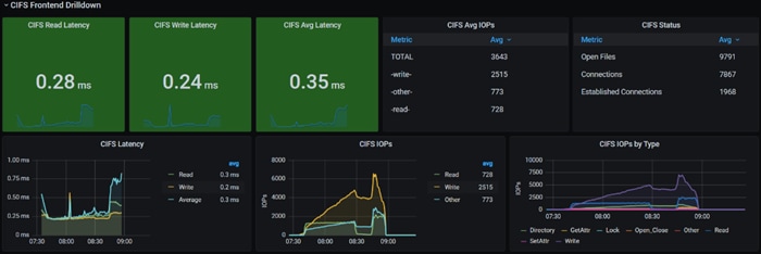
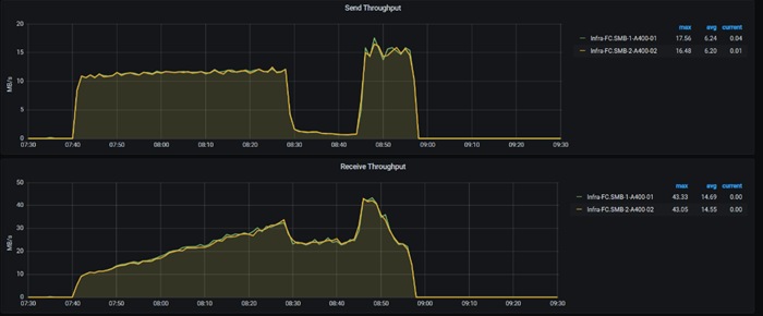
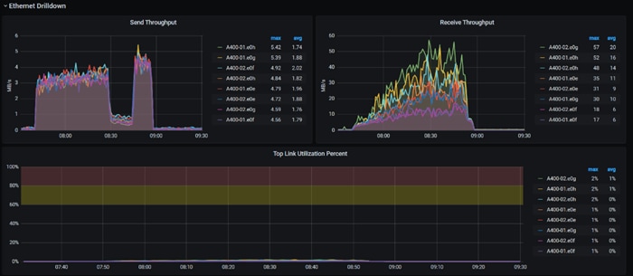
FlexGroup
IOPS for PVS FlexGroup remained close to zero and we didn’t include in the graph. As expected, Data FlexGroup had more IOPS and spiked during user logoff process.
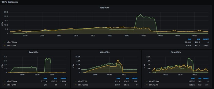
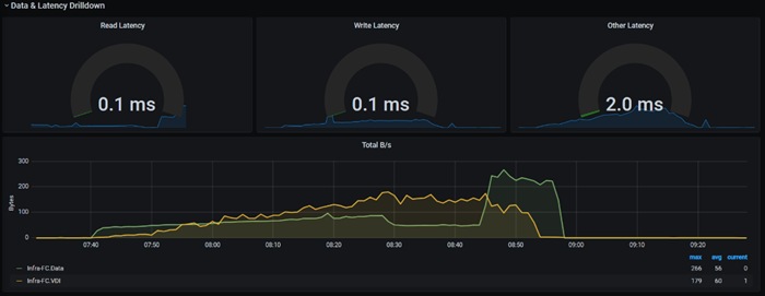
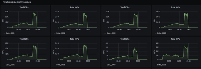
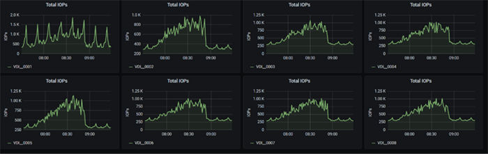
Storage Nodes
CPU resource utilization is below 25% and can be considered as underutilized. It has headroom to add more workloads.
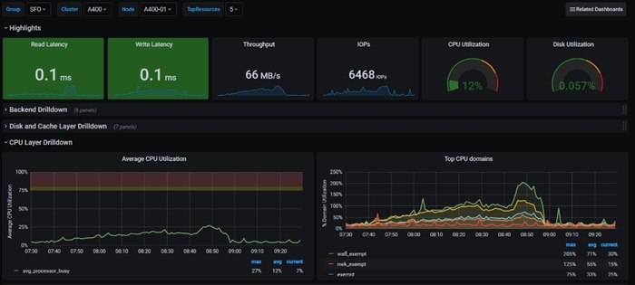
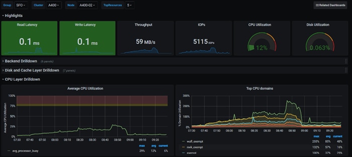
The QoS policies ensured each group of workloads were provisioned with minimum required IOPS to meet the application need. Users could create multiple QoS polices addressing different levels of performance, and the policies could be changed dynamically and is completely transparent to the workloads. The policies mentioned above were configured a Max limit as well, to avoid over consumption of performance resources
For this use case- HR, Sales, and Engineer workloads were created to show performance in a mix workload environment using NetApp’s QoS policies.
qos policy-group modify -policy-group ENG -vserver <v-servername> -is-shared true -max-throughput 40840IOPS -min-throughput 24456IOPS
qos policy-group modify -policy-group SALES -vserver <v-servername> -is-shared true -max-throughput 32648IOPS -min-throughput 16384IOPS
qos policy-group modify -policy-group HR -vserver <v-servername> -is-shared true -max-throughput 24456IOPS -min-throughput 8192IOPS
The Desktop group is designed with 3 separate catalogs HR, Sales, and Engineering. All machines from each catalog are added to the same Desktop group and Citrix’s power policy is managing the bootup of the Desktop group.
The following images show the performance during the boot up process of 5000 vms spread across 3 catalog workloads.
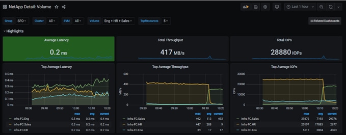
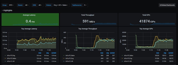
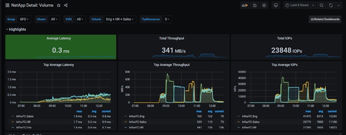
The following image shows the performance of the system once the vms are up, idle, and stable. Citrix boots one catalog in the group at a time. After all are up and registered, we waited 15 mins for settling time for the host CPUs, then the test ran for 63 mins. 48 mins to login users and 15 mins of steady state.
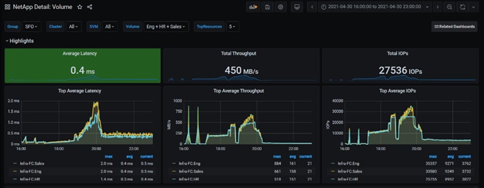
Scalability Considerations and Guidelines
There are many factors to consider when you begin to scale beyond 6000 users, which this reference architecture has successfully tested. This 6000-seat solution provides a large-scale building block that can be replicated to confidently scale-out to tens of thousands of users.
As our results indicate, we have proven linear scalability in the Cisco UCS Reference Architecture as tested:
● Cisco UCS Manager Software supports up to 20 Cisco UCS chassis within a single Cisco UCS domain with Cisco UCS 6454 Fabric Interconnect. A single UCS domain can grow to 160 blades for an enterprise deployment.
● Cisco UCS Central, the manager of managers, extends UCS domains and vastly increases the reach of the Cisco UCS system. Simplify daily operations by centrally managing and automating routine tasks and expediting problem resolution. Our powerful platform eliminates disparate management environments. Use it to support up to 10,000 Cisco UCS servers (blade, rack, composable, and Mini) and manage multiple Cisco UCS instances or domains across globally-distributed locations.
● As scale grows, the value of the combined Cisco UCS fabric, Cisco Nexus physical switches, and Cisco Nexus virtual switches increases dramatically to define the Quality of Services required to deliver excellent end user experience 100 percent of the time.
● To accommodate the Cisco Nexus 9000 upstream connectivity in the way we describe in the network configuration section, two Ethernet uplinks are needed to be configured on the Cisco UCS 6454 Fabric Interconnect.
The backend storage has to be scaled accordingly, based on the IOP considerations as described in the following NetApp scaling section.
NetApp FAS Storage Guidelines for Scale Desktop Virtualization Workloads
Storage sizing has three steps:
1. Gathering solution requirements
2. Estimating storage capacity and performance
3. Obtaining recommendations for the storage configuration
Solution Assessment
Assessment is an important first step. Liquidware Labs Stratusphere FIT, and Lakeside VDI Assessment are recommended to collect network, server, and storage requirements. NetApp has contracted with Liquidware Labs to provide free licenses to NetApp employees and channel partners. For information on how to obtain software and licenses, refer to this FAQ. Liquidware Labs also provides a storage template that fits the NetApp system performance modeler. For guidelines on how to use Stratusphere FIT and the NetApp custom report template, refer to TR-3902: Guidelines for Virtual Desktop Storage Profiling.
Virtual desktop sizing depends on the following:
● The number of the seats
● The VM workload (applications, VM size, and VM OS)
● The connection broker (Citrix Virtual Apps & Desktops)
● The hypervisor type (vSphere, Citrix Hypervisor, or Hyper-V)
● The provisioning method (NetApp clone, Linked clone, PVS, and MCS)
● Future storage growth
● Disaster recovery requirements
● User home directories
NetApp has developed a sizing tool called the System Performance Modeler (SPM) that simplifies the process of performance sizing for NetApp systems. It has a step-by-step wizard to support varied workload requirements and provides recommendations for meeting your performance needs.
Storage sizing has two factors: capacity and performance. NetApp recommends using the NetApp SPM tool to size the virtual desktop solution. To use this tool, contact NetApp partners and NetApp sales engineers who have the access to SPM. When using the NetApp SPM to size a solution, NetApp recommends separately sizing the VDI workload (including the write cache and personal vDisk if used), and the CIFS profile and home directory workload. When sizing CIFS, NetApp recommends sizing with a heavy user workload. Eighty percent concurrency was assumed in this solution.
Capacity Considerations
Deploying Citrix Virtual Apps & Desktops with PVS imposes the following capacity considerations:
● vDisk. The size of the vDisk depends on the OS and the number of applications installed. It is a best practice to create vDisks larger than necessary in order to leave room for any additional application installations or patches. Each organization should determine the space requirements for its vDisk images.
● As an example, a 20GB vDisk with a Windows 7 image is used. NetApp deduplication can be used for space savings.
● Write cache file. NetApp recommends a size range of 4 to 18GB for each user. Write cache size is based on what type of workload and how often the VM is rebooted. In this example, 4GB is used for the write-back cache. Since NFS is thin provisioned by default, only the space currently used by the VM will be consumed on the NetApp storage. If iSCSI or FCP is used, N x 4GB would be consumed as soon as a new virtual machine is created.
● PvDisk. Normally, 5 to 10GB is allocated, depending on the application and the size of the profile. Use 20 percent of the master image as a starting point. NetApp recommends running deduplication.
● CIFS home directory. Various factors must be considered for each home directory deployment. The key considerations for architecting and sizing a CIFS home directory solution include the number of users, the number of concurrent users, the space requirement for each user, and the network load. Run deduplication to obtain space savings.
● Infrastructure. Host Citrix Virtual Apps & Desktops, PVS, SQL Server, DNS, and DHCP.
The space calculation formula for a 2000-seat deployment is as follows: Number of vDisk x 20GB + 2000 x 4GB write cache + 2000 x 10GB PvDisk + 2000 x 5GB user home directory x 70% + 2000 x 1GB vSwap + 500GB infrastructure.
Performance Considerations
The collection of performance requirements is a critical step. After using Liquidware Labs Stratusphere FIT and Lakeside VDI Assessment to gather I/O requirements, contact the NetApp account team to obtain recommended software and hardware configurations.
Size, the read/write ratio, and random or sequential reads comprise the I/O considerations. We use 90 percent write and 10 percent read for PVS workload. Storage CPU utilization must also be considered. Table 83 can be used as guidance for your sizing calculations for a PVS workload when using a LoginVSI heavy workload.
Table 20. Typical IOPS without RamCache plus Overflow Feature
|
|
Boot IOPS |
Login IOPS |
Steady IOPS |
| Write Cache (NFS) |
8-10 |
9 |
7.5 |
| vDisk (CIFS SMB 3) |
0.5 |
0 |
0 |
| Infrastructure (NFS) |
2 |
1.5 |
0 |
Scalability of Citrix Virtual Apps & Desktops 1912 LTSR Configuration
Citrix Virtual Apps & Desktops environments can scale to large numbers. When implementing Citrix Virtual Apps & Desktops, consider the following in scaling the number of hosted shared and hosted virtual desktops:
● Types of storage in your environment
● Types of desktops that will be deployed
● Data protection requirements
● For Citrix Provisioning Server pooled desktops, the write cache sizing and placement
When designing and deploying this CVD environment Cisco and Citrix recommends using N+1 schema for virtualization host servers to accommodate resiliency. In all reference architectures (such as this CVD), this recommendation is applied to all host servers.
Appendix A Cisco Switch Configuration
!Command: show running-config
!
version 7.0(3)I1(3b)
switchname DV-Pod-2-N9K-A
class-map type network-qos class-platinum
match qos-group 2
class-map type network-qos class-all-flood
match qos-group 2
class-map type network-qos system_nq_policy
match qos-group 2
class-map type network-qos class-ip-multicast
match qos-group 2
policy-map type network-qos jumbo
class type network-qos class-platinum
mtu 9216
class type network-qos class-default
mtu 9216
vdc DV-Pod-2-N9K-A id 1
limit-resource vlan minimum 16 maximum 4094
limit-resource vrf minimum 2 maximum 4096
limit-resource port-channel minimum 0 maximum 511
limit-resource u4route-mem minimum 248 maximum 248
limit-resource u6route-mem minimum 96 maximum 96
limit-resource m4route-mem minimum 58 maximum 58
limit-resource m6route-mem minimum 8 maximum 8
feature telnet
cfs ipv4 distribute
cfs eth distribute
feature interface-vlan
feature hsrp
feature lacp
feature dhcp
feature vpc
feature lldp
clock protocol none vdc 1
no password strength-check
username admin password 5 $1$tYYajkfc$7P7nLjWYvfTWAlvFDnwJZ. role network-admin
ip domain-lookup
ip access-list NFS_VLAN63
10 permit ip 10.10.63.0 255.255.255.0 any
20 deny ip any any
ip access-list iSCSI-A_64
10 permit ip 10.10.64.0 255.255.255.0 any
20 deny ip any any
ip access-list iSCSI-B_65
10 permit ip 10.10.65.0 255.255.255.0 any
20 deny ip any any
class-map type qos match-any class-platinum
match cos 5
policy-map type qos jumbo
class class-platinum
set qos-group 2
class class-default
set qos-group 0
system qos
service-policy type network-qos jumbo
copp profile strict
snmp-server user admin network-admin auth md5 0xf747567d6cfecf362a9641ac6f3cefc9 priv 0xf747567d6cfecf362a9641ac6f3cefc9 localizedkey
rmon event 1 log trap public description FATAL(1) owner PMON@FATAL
rmon event 2 log trap public description CRITICAL(2) owner PMON@CRITICAL
rmon event 3 log trap public description ERROR(3) owner PMON@ERROR
rmon event 4 log trap public description WARNING(4) owner PMON@WARNING
rmon event 5 log trap public description INFORMATION(5) owner PMON@INFO
ntp server 10.81.254.202
vlan 1-2,60-70,102,164
vlan 60
name In-Band-Mgmt
vlan 61
name Infra-Mgmt
vlan 62
name CIFS
vlan 63
name NFS
vlan 64
name iSCSI-A
vlan 65
name iSCSI-B
vlan 66
name vMotion
vlan 67
name N1KV
vlan 68
name LauncherPXE
vlan 69
name Launcher81
vlan 70
name other-3
vlan 102
name VDI
vlan 164
name Out-Of-Band-Mgmt
spanning-tree port type edge bpduguard default
spanning-tree port type edge bpdufilter default
spanning-tree port type network default
service dhcp
ip dhcp relay
ipv6 dhcp relay
vrf context management
ip route 0.0.0.0/0 10.29.164.1
port-channel load-balance src-dst l4port
vpc domain 10
peer-switch
role priority 10
peer-keepalive destination 10.29.164.66 source 10.29.164.65
delay restore 150
peer-gateway
auto-recovery
interface Vlan1
no ip redirects
no ipv6 redirects
interface Vlan2
description Default native vlan 2
no ip redirects
no ipv6 redirects
interface Vlan60
description Out of Band Management vlan 60
no shutdown
no ip redirects
ip address 10.10.60.2/24
no ipv6 redirects
hsrp version 2
hsrp 60
preempt
priority 110
ip 10.10.60.1
interface Vlan61
description Infrastructure vlan 61
no shutdown
no ip redirects
ip address 10.10.61.2/24
no ipv6 redirects
hsrp version 2
hsrp 61
preempt
ip 10.10.61.1
interface Vlan62
description CIFS vlan 62
no shutdown
no ip redirects
ip address 10.10.62.2/24
no ipv6 redirects
hsrp version 2
hsrp 62
preempt
priority 110
ip 10.10.62.1
interface Vlan63
no shutdown
no ip redirects
ip address 10.10.63.2/24
no ipv6 redirects
hsrp version 2
hsrp 63
preempt
ip 10.10.63.1
interface Vlan64
description iSCSI Fabric A path vlan 64
no shutdown
no ip redirects
ip address 10.10.64.2/24
no ipv6 redirects
hsrp version 2
hsrp 64
preempt
priority 110
ip 10.10.64.1
interface Vlan65
description iSCSI Fabric B path vlan 65
no shutdown
no ip redirects
ip address 10.10.65.2/24
no ipv6 redirects
hsrp version 2
hsrp 65
preempt
ip 10.10.65.1
interface Vlan66
description vMotion network vlan 66
no shutdown
ip address 10.10.66.2/24
hsrp version 2
hsrp 66
preempt
ip 10.10.66.1
interface Vlan67
description vlan 67
no shutdown
ip address 10.10.67.2/24
hsrp version 2
hsrp 67
preempt
ip 10.10.67.1
interface Vlan68
description LoginVSI Launchers vlan 68
no shutdown
no ip redirects
ip address 10.10.68.2/24
no ipv6 redirects
hsrp version 2
hsrp 68
preempt
ip 10.10.68.1
interface Vlan69
description LoginVSI Launchers 10.10.81-network vlan 69
no shutdown
no ip redirects
ip address 10.10.81.2/24
no ipv6 redirects
hsrp version 2
hsrp 69
preempt
ip 10.10.81.1
interface Vlan102
description VDI vlan 102
no shutdown
no ip redirects
ip address 10.2.0.2/19
no ipv6 redirects
hsrp version 2
hsrp 102
preempt delay minimum 240
priority 110
timers 1 3
ip 10.2.0.1
ip dhcp relay address 10.10.61.30
interface port-channel10
description VPC-PeerLink
switchport mode trunk
switchport trunk allowed vlan 1-2,60-70,102,164
spanning-tree port type network
vpc peer-link
interface port-channel11
description FI-A_6k_UCS-Uplink
switchport mode trunk
switchport trunk allowed vlan 1-2,60-70,102,164
spanning-tree port type edge trunk
mtu 9216
vpc 11
interface port-channel12
description FI-B_6k_UCS-Uplink
switchport mode trunk
switchport trunk allowed vlan 1-2,60-70,102,164
spanning-tree port type edge trunk
mtu 9216
vpc 12
interface port-channel13
description NetApp_AFF400_Node_02_CIFS
switchport mode trunk
switchport trunk allowed vlan 62,64-65
spanning-tree port type edge trunk
mtu 9216
vpc 13
interface port-channel14
description NetApp_AFF400_Node_02_NFS
switchport mode trunk
switchport trunk allowed vlan 63
spanning-tree port type edge trunk
mtu 9216
vpc 14
interface port-channel15
description FI-A_6k_Launchers-Uplink
switchport mode trunk
switchport trunk allowed vlan 1-2,60-70,102,164
spanning-tree port type edge trunk
mtu 9216
vpc 15
interface port-channel16
description FI-B_6k_Launchers-Uplink
switchport mode trunk
switchport trunk allowed vlan 1-2,60-70,102,164
spanning-tree port type edge trunk
mtu 9216
vpc 16
interface port-channel17
description NetApp_AFF400_Node_01_CIFS
switchport mode trunk
switchport trunk allowed vlan 62,64-65
spanning-tree port type edge trunk
mtu 9216
vpc 17
interface port-channel18
description NetApp_AFF400_Node_01_NFS
switchport mode trunk
switchport trunk allowed vlan 63
spanning-tree port type edge trunk
mtu 9216
vpc 18
interface Ethernet1/1
description NetApp_AFF400_Node-02_port_e0e_NFS
switchport mode trunk
switchport trunk allowed vlan 63
mtu 9216
channel-group 14 mode active
interface Ethernet1/2
description NetApp_AFF400_Node-02_port_e1a_NFS
switchport mode trunk
switchport trunk allowed vlan 63
mtu 9216
channel-group 14 mode active
interface Ethernet1/3
description NetApp_AFF400_Node-01_port_e0e_NFS
switchport mode trunk
switchport trunk allowed vlan 63
mtu 9216
channel-group 18 mode active
interface Ethernet1/4
description NetApp_AFF400_Node-01_port_e4a_NFS
switchport mode trunk
switchport trunk allowed vlan 63
mtu 9216
channel-group 18 mode active
interface Ethernet1/5
description NetApp_AFF400_Node-02_port_e0f_CIFS
switchport mode trunk
switchport trunk allowed vlan 62,64-65
mtu 9216
channel-group 13 mode active
interface Ethernet1/6
description NetApp_AFF400_Node-02_port_e4a_CIFS
switchport mode trunk
switchport trunk allowed vlan 62,64-65
mtu 9216
channel-group 13 mode active
interface Ethernet1/7
description NetApp_AFF400_Node-01_port_e0f_CIFS
switchport mode trunk
switchport trunk allowed vlan 62,64-65
mtu 9216
channel-group 17 mode active
interface Ethernet1/8
description NetApp_AFF400_Node-01_port_e1a_CIFS
switchport mode trunk
switchport trunk allowed vlan 62,64-65
mtu 9216
channel-group 17 mode active
interface Ethernet1/9
interface Ethernet1/10
interface Ethernet1/11
interface Ethernet1/12
interface Ethernet1/13
interface Ethernet1/14
interface Ethernet1/15
interface Ethernet1/16
interface Ethernet1/17
description Uplink_from_FI-A_6k
switchport mode trunk
switchport trunk allowed vlan 1-2,60-70,102,164
mtu 9216
channel-group 11 mode active
interface Ethernet1/18
description Uplink_from_FI-A_6k
switchport mode trunk
switchport trunk allowed vlan 1-2,60-70,102,164
mtu 9216
channel-group 11 mode active
interface Ethernet1/19
description Uplink_from_FI-B_6k
switchport mode trunk
switchport trunk allowed vlan 1-2,60-70,102,164
mtu 9216
channel-group 12 mode active
interface Ethernet1/20
description Uplink_from_FI-B_6k
switchport mode trunk
switchport trunk allowed vlan 1-2,60-70,102,164
mtu 9216
channel-group 12 mode active
interface Ethernet1/21
interface Ethernet1/22
interface Ethernet1/23
interface Ethernet1/24
interface Ethernet1/25
interface Ethernet1/26
interface Ethernet1/27
interface Ethernet1/28
interface Ethernet1/29
interface Ethernet1/30
interface Ethernet1/31
interface Ethernet1/32
interface Ethernet1/33
interface Ethernet1/34
interface Ethernet1/35
interface Ethernet1/36
interface Ethernet1/37
interface Ethernet1/38
interface Ethernet1/39
interface Ethernet1/40
interface Ethernet1/41
interface Ethernet1/42
interface Ethernet1/43
interface Ethernet1/44
interface Ethernet1/45
description Uplink_from_LoginVSI_Launchers_FI-A
switchport mode trunk
switchport trunk allowed vlan 1-2,60-70,102,164
mtu 9216
channel-group 15 mode active
interface Ethernet1/46
description Uplink_from_LoginVSI_Launchers_FI-B
switchport mode trunk
switchport trunk allowed vlan 1-2,60-70,102,164
mtu 9216
channel-group 16 mode active
interface Ethernet1/47
interface Ethernet1/48
description TOR
switchport access vlan 164
interface Ethernet1/49
description VPC Peer Link between 9ks
switchport mode trunk
switchport trunk allowed vlan 1-2,60-70,102,164
channel-group 10 mode active
interface Ethernet1/50
description VPC Peer Link between 9ks
switchport mode trunk
switchport trunk allowed vlan 1-2,60-70,102,164
channel-group 10 mode active
interface Ethernet1/51
interface Ethernet1/52
interface Ethernet1/53
interface Ethernet1/54
interface mgmt0
vrf member management
ip address 10.29.164.65/24
line console
line vty
boot nxos bootflash://sup-1/n9000-dk9.7.0.3.I1.3b.bin
!Command: show running-config
!Time: Fri Feb 26 16:47:01 2016
version 7.0(3)I1(3b)
switchname DV-Pod-2-N9K-B
class-map type network-qos class-platinum
match qos-group 2
class-map type network-qos class-all-flood
match qos-group 2
class-map type network-qos system_nq_policy
match qos-group 2
class-map type network-qos class-ip-multicast
match qos-group 2
policy-map type network-qos jumbo
class type network-qos class-platinum
mtu 9216
class type network-qos class-default
mtu 9216
vdc DV-Pod-2-N9K-B id 1
limit-resource vlan minimum 16 maximum 4094
limit-resource vrf minimum 2 maximum 4096
limit-resource port-channel minimum 0 maximum 511
limit-resource u4route-mem minimum 248 maximum 248
limit-resource u6route-mem minimum 96 maximum 96
limit-resource m4route-mem minimum 58 maximum 58
limit-resource m6route-mem minimum 8 maximum 8
feature telnet
cfs ipv4 distribute
cfs eth distribute
feature interface-vlan
feature hsrp
feature lacp
feature dhcp
feature vpc
feature lldp
clock protocol none vdc 1
no password strength-check
username admin password 5 $1$fp3LrGLC$PF8eML85qkPBgdH/bZAKK/ role network-admin
ip domain-lookup
ip access-list NFS_VLAN63
10 permit ip 10.10.63.0 255.255.255.0 any
20 deny ip any any
ip access-list iSCSI-A_64
10 permit ip 10.10.64.0 255.255.255.0 any
20 deny ip any any
ip access-list iSCSI-B_65
10 permit ip 10.10.65.0 255.255.255.0 any
20 deny ip any any
class-map type qos match-any class-platinum
match cos 5
policy-map type qos jumbo
class class-platinum
set qos-group 2
class class-default
set qos-group 0
system qos
service-policy type network-qos jumbo
copp profile strict
snmp-server user admin network-admin auth md5 0x13ec164cc65d2b9854d70379681039c8 priv 0x13ec164cc65d2b9854d70379681039c8 localizedkey
ntp master 8
vlan 1-2,60-70,102,164
vlan 60
name In-Band-Mgmt
vlan 61
name Infra-Mgmt
vlan 62
name CIFS
vlan 63
name NFS
vlan 64
name iSCSI-A
vlan 65
name iSCSI-B
vlan 66
name vMotion
vlan 67
name N1KV
vlan 68
name LauncherPXE
vlan 69
name Launcher81
vlan 70
name other-3
vlan 102
name VDI
vlan 164
name Out-Of-Band-Mgmt
spanning-tree port type edge bpduguard default
spanning-tree port type edge bpdufilter default
spanning-tree port type network default
service dhcp
ip dhcp relay
ipv6 dhcp relay
vrf context management
ip route 0.0.0.0/0 10.29.164.1
port-channel load-balance src-dst l4port
vpc domain 10
peer-switch
role priority 10
peer-keepalive destination 10.29.164.65 source 10.29.164.66
delay restore 150
peer-gateway
auto-recovery
interface Vlan1
no ip redirects
no ipv6 redirects
interface Vlan2
description Default native vlan 2
no ip redirects
no ipv6 redirects
interface Vlan60
description Out of Band Management vlan 60
no shutdown
no ip redirects
ip address 10.10.60.3/24
no ipv6 redirects
hsrp version 2
hsrp 60
preempt
priority 110
ip 10.10.60.1
interface Vlan61
description Infrastructure vlan 61
no shutdown
no ip redirects
ip address 10.10.61.3/24
no ipv6 redirects
hsrp version 2
hsrp 61
preempt
ip 10.10.61.1
interface Vlan62
description CIFS vlan 62
no shutdown
no ip redirects
ip address 10.10.62.3/24
no ipv6 redirects
hsrp version 2
hsrp 62
preempt
priority 110
ip 10.10.62.1
interface Vlan63
description NFS vlan 63
no shutdown
no ip redirects
ip address 10.10.63.3/24
no ipv6 redirects
hsrp version 2
hsrp 63
preempt
ip 10.10.63.1
interface Vlan64
description iSCSI Fabric A path vlan 64
no shutdown
no ip redirects
ip address 10.10.64.3/24
no ipv6 redirects
hsrp version 2
hsrp 64
preempt
priority 110
ip 10.10.64.1
interface Vlan65
description iSCSI Fabric B path vlan 65
no shutdown
no ip redirects
ip address 10.10.65.3/24
no ipv6 redirects
hsrp version 2
hsrp 65
preempt
ip 10.10.65.1
interface Vlan66
description vMotion network vlan 66
no shutdown
ip address 10.10.66.3/24
hsrp version 2
hsrp 66
preempt
ip 10.10.66.1
interface Vlan67
description vlan 67
no shutdown
ip address 10.10.67.3/24
hsrp version 2
hsrp 67
preempt
ip 10.10.67.1
interface Vlan68
description LoginVSI Launchers vlan 68
no shutdown
no ip redirects
ip address 10.10.68.3/24
no ipv6 redirects
hsrp version 2
hsrp 68
preempt
ip 10.10.68.1
interface Vlan69
description LoginVSI Launchers 10.10.81-network vlan 69
no shutdown
no ip redirects
ip address 10.10.81.3/24
no ipv6 redirects
hsrp version 2
hsrp 69
preempt
ip 10.10.81.1
interface Vlan102
description VDI vlan 102
no shutdown
no ip redirects
ip address 10.2.0.3/19
no ipv6 redirects
hsrp version 2
hsrp 102
preempt delay minimum 240
priority 110
timers 1 3
ip 10.2.0.1
ip dhcp relay address 10.10.61.30
interface port-channel10
description VPC-PeerLink
switchport mode trunk
switchport trunk allowed vlan 1-2,60-70,102,164
spanning-tree port type network
vpc peer-link
interface port-channel11
description FI-A_6k_UCS-Uplink
switchport mode trunk
switchport trunk allowed vlan 1-2,60-70,102,164
spanning-tree port type edge trunk
mtu 9216
vpc 11
interface port-channel12
description FI-B_6k_UCS-Uplink
switchport mode trunk
switchport trunk allowed vlan 1-2,60-70,102,164
spanning-tree port type edge trunk
mtu 9216
vpc 12
interface port-channel13
description NetApp_AFF400_Node_02_CIFS
switchport mode trunk
switchport trunk allowed vlan 62,64-65
spanning-tree port type edge trunk
mtu 9216
vpc 13
interface port-channel14
description NetApp_AFF400_Node_02_NFS
switchport mode trunk
switchport trunk allowed vlan 63
spanning-tree port type edge trunk
mtu 9216
vpc 14
interface port-channel15
description FI-A_6k_Launchers-Uplink
switchport mode trunk
switchport trunk allowed vlan 1-2,60-70,102,164
spanning-tree port type edge trunk
mtu 9216
vpc 15
interface port-channel16
description FI-B_6k_Launchers-Uplink
switchport mode trunk
switchport trunk allowed vlan 1-2,60-70,102,164
spanning-tree port type edge trunk
mtu 9216
vpc 16
interface port-channel17
description NetApp_AFF400_Node_01_CIFS
switchport mode trunk
switchport trunk allowed vlan 62,64-65
spanning-tree port type edge trunk
mtu 9216
vpc 17
interface port-channel18
description NetApp_AFF400_Node-01_port_NFS
switchport mode trunk
switchport trunk allowed vlan 63
spanning-tree port type edge trunk
mtu 9216
vpc 18
interface Ethernet1/1
description NetApp_AFF400_Node-02_port_e0g_NFS
switchport mode trunk
switchport trunk allowed vlan 63
mtu 9216
channel-group 14 mode active
interface Ethernet1/2
description NetApp_AFF400_Node-02_port_e1b_NFS
switchport mode trunk
switchport trunk allowed vlan 63
mtu 9216
channel-group 14 mode active
interface Ethernet1/3
description NetApp_AFF400_Node-01_port_e0g_NFS
switchport mode trunk
switchport trunk allowed vlan 63
mtu 9216
channel-group 18 mode active
interface Ethernet1/4
description NetApp_AFF400_Node-01_port_e4b_NFS
switchport mode trunk
switchport trunk allowed vlan 63
mtu 9216
channel-group 18 mode active
interface Ethernet1/5
description NetApp_AFF400_Node-02_port_e0h_CIFS
switchport mode trunk
switchport trunk allowed vlan 62,64-65
mtu 9216
channel-group 13 mode active
interface Ethernet1/6
description NetApp_AFF400_Node-02_port_e4b_CIFS
switchport mode trunk
switchport trunk allowed vlan 62,64-65
mtu 9216
channel-group 13 mode active
interface Ethernet1/7
description NetApp_AFF400_Node-01_port_e0h_CIFS
switchport mode trunk
switchport trunk allowed vlan 62,64-65
mtu 9216
channel-group 17 mode active
interface Ethernet1/8
description NetApp_AFF400_Node-01_port_e1b_CIFS
switchport mode trunk
switchport trunk allowed vlan 62,64-65
mtu 9216
channel-group 17 mode active
interface Ethernet1/9
description Jumphost ToR
switchport access vlan 60
spanning-tree port type edge
speed 1000
interface Ethernet1/10
interface Ethernet1/11
interface Ethernet1/12
interface Ethernet1/13
interface Ethernet1/14
interface Ethernet1/15
interface Ethernet1/16
interface Ethernet1/17
description Uplink_from_FI-A_6k
switchport mode trunk
switchport trunk allowed vlan 1-2,60-70,102,164
mtu 9216
channel-group 11 mode active
interface Ethernet1/18
description Uplink_from_FI-A_6k
switchport mode trunk
switchport trunk allowed vlan 1-2,60-70,102,164
mtu 9216
channel-group 11 mode active
interface Ethernet1/19
description Uplink_from_FI-B_6k
switchport mode trunk
switchport trunk allowed vlan 1-2,60-70,102,164
mtu 9216
channel-group 12 mode active
interface Ethernet1/20
description Uplink_from_FI-B_6k
switchport mode trunk
switchport trunk allowed vlan 1-2,60-70,102,164
mtu 9216
channel-group 12 mode active
interface Ethernet1/21
interface Ethernet1/22
interface Ethernet1/23
interface Ethernet1/24
interface Ethernet1/25
interface Ethernet1/26
interface Ethernet1/27
interface Ethernet1/28
interface Ethernet1/29
interface Ethernet1/30
interface Ethernet1/31
interface Ethernet1/32
interface Ethernet1/33
interface Ethernet1/34
interface Ethernet1/35
interface Ethernet1/36
interface Ethernet1/37
interface Ethernet1/38
interface Ethernet1/39
interface Ethernet1/40
interface Ethernet1/41
interface Ethernet1/42
interface Ethernet1/43
interface Ethernet1/44
interface Ethernet1/45
description Uplink_from_LoginVSI_Launchers_FI-A
switchport mode trunk
switchport trunk allowed vlan 1-2,60-70,102,164
mtu 9216
channel-group 15 mode active
interface Ethernet1/46
description Uplink_from_LoginVSI_Launchers_FI-B
switchport mode trunk
switchport trunk allowed vlan 1-2,60-70,102,164
mtu 9216
channel-group 16 mode active
interface Ethernet1/47
interface Ethernet1/48
description TOR
switchport access vlan 164
interface Ethernet1/49
description VPC Peer Link between 9ks
switchport mode trunk
switchport trunk allowed vlan 1-2,60-70,102,164
channel-group 10 mode active
interface Ethernet1/50
description VPC Peer Link between 9ks
switchport mode trunk
switchport trunk allowed vlan 1-2,60-70,102,164
channel-group 10 mode active
interface Ethernet1/51
interface Ethernet1/52
interface Ethernet1/53
interface Ethernet1/54
interface mgmt0
vrf member management
ip address 10.29.164.66/24
line console
line vty
boot nxos bootflash://sup-1/n9000-dk9.7.0.3.I1.3b.bin
Cisco MDS 9132T - A Configuration
!Command: show running-config
!Time: Wed Feb 7 00:49:39 2018
version 8.1(1)
power redundancy-mode redundant
feature npiv
feature fport-channel-trunk
role name default-role
description This is a system defined role and applies to all users.
rule 5 permit show feature environment
rule 4 permit show feature hardware
rule 3 permit show feature module
rule 2 permit show feature snmp
rule 1 permit show feature system
no password strength-check
username admin password 5 $1$DDq8vF1x$EwCSM0O3dlXZ4jlPy9ZoC. role network-admin
ip domain-lookup
ip host MDS-A 10.29.164.238
aaa group server radius radius
snmp-server contact jnichols
snmp-server user admin network-admin auth md5 0x2efbf582e573df2038164f1422c231fe
priv 0x2efbf582e573df2038164f1422c231fe localizedkey
snmp-server host 10.155.160.192 traps version 2c public udp-port 1163
snmp-server host 10.155.166.14 traps version 2c public udp-port 1163
snmp-server host 10.29.132.18 traps version 2c public udp-port 1163
snmp-server host 10.29.164.130 traps version 2c public udp-port 1163
snmp-server host 10.29.164.250 traps version 2c public udp-port 1164
rmon event 1 log trap public description FATAL(1) owner PMON@FATAL
rmon event 2 log trap public description CRITICAL(2) owner PMON@CRITICAL
rmon event 3 log trap public description ERROR(3) owner PMON@ERROR
rmon event 4 log trap public description WARNING(4) owner PMON@WARNING
rmon event 5 log trap public description INFORMATION(5) owner PMON@INFO
snmp-server community public group network-operator
vsan database
vsan 400 name "FlexPod-A"
device-alias database
device-alias name B200M5-SP pwwn 20:00:00:25:b5:03:9a:06
device-alias name A400_N1P3 pwwn 50:01:73:80:59:16:01:12
device-alias name A400_N2P1 pwwn 50:01:73:80:59:16:01:20
device-alias name A400_N2P3 pwwn 50:01:73:80:59:16:01:22
device-alias name A400_N3P1 pwwn 50:01:73:80:59:16:01:30
device-alias name A400_N3P3 pwwn 50:01:73:80:59:16:01:32
device-alias name VDI-1-hba1 pwwn 20:00:00:25:b5:3a:00:3f
device-alias name VDI-2-hba1 pwwn 20:00:00:25:b5:3a:00:0f
device-alias name VDI-3-hba1 pwwn 20:00:00:25:b5:3a:00:1f
device-alias name VDI-4-hba1 pwwn 20:00:00:25:b5:3a:00:4e
device-alias name VDI-5-hba1 pwwn 20:00:00:25:b5:3a:00:2e
device-alias name VDI-6-hba1 pwwn 20:00:00:25:b5:3a:00:3e
device-alias name VDI-7-hba1 pwwn 20:00:00:25:b5:3a:00:0e
device-alias name VDI-9-hba1 pwwn 20:00:00:25:b5:3a:00:4d
device-alias name A400-01-0g pwwn 20:01:00:a0:98:af:bd:e8
device-alias name A400-02-0g pwwn 20:03:00:a0:98:af:bd:e8
device-alias name srv01_HBA1 pwwn 20:00:00:25:b5:03:9a:12
device-alias name srv02_HBA1 pwwn 20:00:00:25:b5:03:9a:14
device-alias name srv03_HBA1 pwwn 20:00:00:25:b5:03:9a:0e
device-alias name srv04_HBA1 pwwn 20:00:00:25:b5:03:9a:00
device-alias name srv05_HBA1 pwwn 20:00:00:25:b5:03:9a:02
device-alias name srv06_HBA1 pwwn 20:00:00:25:b5:03:9a:0c
device-alias name srv07_HBA1 pwwn 20:00:00:25:b5:03:9a:10
device-alias name srv09_HBA1 pwwn 20:00:00:25:b5:03:9a:16
device-alias name srv10_HBA1 pwwn 20:00:00:25:b5:03:9a:18
device-alias name srv11_HBA1 pwwn 20:00:00:25:b5:03:9a:1a
device-alias name srv12_HBA1 pwwn 20:00:00:25:b5:03:9a:1c
device-alias name srv13_HBA1 pwwn 20:00:00:25:b5:03:9a:1e
device-alias name srv14_HBA1 pwwn 20:00:00:25:b5:03:9a:20
device-alias name srv15_HBA1 pwwn 20:00:00:25:b5:03:9a:22
device-alias name srv17_HBA1 pwwn 20:00:00:25:b5:03:9a:24
device-alias name srv18_HBA1 pwwn 20:00:00:25:b5:03:9a:26
device-alias name srv19_HBA1 pwwn 20:00:00:25:b5:03:9a:30
device-alias name srv20_HBA1 pwwn 20:00:00:25:b5:03:9a:28
device-alias name srv21_HBA1 pwwn 20:00:00:25:b5:03:9a:2a
device-alias name srv22_HBA1 pwwn 20:00:00:25:b5:03:9a:2c
device-alias name srv23_HBA1 pwwn 20:00:00:25:b5:03:9a:2e
device-alias name srv24_HBA1 pwwn 20:00:00:25:b5:03:9a:32
device-alias name srv27_HBA1 pwwn 20:00:00:25:b5:03:9a:38
device-alias name VDI-10-hba1 pwwn 20:00:00:25:b5:3a:00:2d
device-alias name VDI-11-hba1 pwwn 20:00:00:25:b5:3a:00:3d
device-alias name VDI-12-hba1 pwwn 20:00:00:25:b5:3a:00:0d
device-alias name VDI-13-hba1 pwwn 20:00:00:25:b5:3a:00:1d
device-alias name VDI-14-hba1 pwwn 20:00:00:25:b5:3a:00:4c
device-alias name VDI-15-hba1 pwwn 20:00:00:25:b5:3a:00:2c
device-alias name VDI-17-hba1 pwwn 20:00:00:25:b5:3a:00:0c
device-alias name VDI-18-hba1 pwwn 20:00:00:25:b5:3a:00:1c
device-alias name VDI-19-hba1 pwwn 20:00:00:25:b5:3a:00:4b
device-alias name VDI-20-hba1 pwwn 20:00:00:25:b5:3a:00:2b
device-alias name VDI-21-hba1 pwwn 20:00:00:25:b5:3a:00:3b
device-alias name VDI-22-hba1 pwwn 20:00:00:25:b5:3a:00:0b
device-alias name VDI-23-hba1 pwwn 20:00:00:25:b5:3a:00:1b
device-alias name VDI-24-hba1 pwwn 20:00:00:25:b5:3a:00:4a
device-alias name VDI-25-hba1 pwwn 20:00:00:25:b5:3a:00:2a
device-alias name VDI-26-hba1 pwwn 20:00:00:25:b5:3a:00:3a
device-alias name VDI-27-hba1 pwwn 20:00:00:25:b5:3a:00:0a
device-alias name VDI-28-hba1 pwwn 20:00:00:25:b5:3a:00:1a
device-alias name VDI-29-hba1 pwwn 20:00:00:25:b5:3a:00:49
device-alias name VDI-30-hba1 pwwn 20:00:00:25:b5:3a:00:39
device-alias name VDI-31-hba1 pwwn 20:00:00:25:b5:3a:00:1e
device-alias name VDI-32-hba1 pwwn 20:00:00:25:b5:3a:00:3c
device-alias name SP-Infra1-fc0 pwwn 20:00:00:25:b5:00:00:2f
device-alias name SP-Infra2-fc0 pwwn 20:00:00:25:b5:00:00:0f
device-alias name SP-VDI-01-fc0 pwwn 20:00:00:25:b5:00:00:2c
device-alias name B200M5-SP_HBA1 pwwn 20:00:00:25:b5:03:9a:04
device-alias name Infra01-8-hba1 pwwn 20:00:00:25:b5:3a:00:4f
device-alias name Infra02-16-hba1 pwwn 20:00:00:25:b5:3a:00:2f
device-alias commit
fcdomain fcid database
vsan 1 wwn 52:4a:93:72:0d:21:6b:11 fcid 0x290000 dynamic
vsan 1 wwn 52:4a:93:72:0d:21:6b:10 fcid 0x290100 dynamic
vsan 1 wwn 20:20:00:2a:6a:d3:df:80 fcid 0x290200 dynamic
vsan 1 wwn 24:01:00:2a:6a:d3:df:80 fcid 0x290400 dynamic
vsan 1 wwn 52:4a:93:72:0d:21:6b:00 fcid 0x290400 dynamic
vsan 1 wwn 50:01:73:80:59:16:01:10 fcid 0x290500 dynamic
vsan 1 wwn 50:01:73:80:59:16:01:20 fcid 0x290600 dynamic
! [A400_N2P1]
vsan 1 wwn 50:01:73:80:59:16:01:30 fcid 0x290700 dynamic
! [A400_N3P1]
vsan 1 wwn 50:01:73:80:59:16:01:12 fcid 0x290800 dynamic
! [A400_N1P3]
vsan 1 wwn 50:01:73:80:59:16:01:22 fcid 0x290900 dynamic
! [A400_N2P3]
vsan 1 wwn 50:01:73:80:59:16:01:32 fcid 0x290a00 dynamic
! [A400_N3P3]
vsan 400 wwn 50:01:73:80:59:16:01:10 fcid 0xa30400 dynamic
vsan 400 wwn 50:01:73:80:59:16:01:20 fcid 0xa30400 dynamic
! [A400_N2P1]
vsan 400 wwn 50:01:73:80:59:16:01:30 fcid 0xa30500 dynamic
! [A400_N3P1]
vsan 400 wwn 50:01:73:80:59:16:01:12 fcid 0xa30600 dynamic
! [A400_N1P3]
vsan 400 wwn 50:01:73:80:59:16:01:22 fcid 0xa30700 dynamic
! [A400_N2P3]
vsan 400 wwn 50:01:73:80:59:16:01:32 fcid 0xa30800 dynamic
! [A400_N3P3]
vsan 1 wwn 20:4d:54:7f:ee:83:42:00 fcid 0x290b00 dynamic
vsan 1 wwn 20:4e:54:7f:ee:83:42:00 fcid 0x290c00 dynamic
vsan 1 wwn 20:4f:54:7f:ee:83:42:00 fcid 0x290d00 dynamic
vsan 1 wwn 20:50:54:7f:ee:83:42:00 fcid 0x290e00 dynamic
vsan 400 wwn 50:0a:09:84:80:d3:67:d3 fcid 0x680000 dynamic
vsan 400 wwn 20:03:00:a0:98:af:bd:e8 fcid 0x680001 dynamic
! [A400-02-0g]
vsan 400 wwn 50:0a:09:84:80:13:41:27 fcid 0x680100 dynamic
vsan 400 wwn 20:01:00:a0:98:af:bd:e8 fcid 0x680101 dynamic
! [A400-01-0g]
vsan 400 wwn 20:02:00:de:fb:90:a0:80 fcid 0x680200 dynamic
vsan 400 wwn 20:03:00:de:fb:90:a0:80 fcid 0x680400 dynamic
vsan 400 wwn 20:04:00:de:fb:90:a0:80 fcid 0x680400 dynamic
vsan 400 wwn 20:01:00:de:fb:90:a0:80 fcid 0x680500 dynamic
vsan 400 wwn 20:00:00:25:b5:3a:00:49 fcid 0x680308 dynamic
! [VDI-29-hba1]
vsan 400 wwn 20:00:00:25:b5:3a:00:1a fcid 0x680415 dynamic
! [VDI-28-hba1]
vsan 400 wwn 20:00:00:25:b5:3a:00:4b fcid 0x680206 dynamic
! [VDI-19-hba1]
vsan 400 wwn 20:00:00:25:b5:3a:00:0a fcid 0x680508 dynamic
! [VDI-27-hba1]
vsan 400 wwn 20:00:00:25:b5:3a:00:0c fcid 0x680307 dynamic
! [VDI-17-hba1]
vsan 400 wwn 20:00:00:25:b5:3a:00:2c fcid 0x680402 dynamic
! [VDI-15-hba1]
vsan 400 wwn 20:00:00:25:b5:3a:00:3a fcid 0x680210 dynamic
! [VDI-26-hba1]
vsan 400 wwn 20:00:00:25:b5:3a:00:4a fcid 0x680505 dynamic
! [VDI-24-hba1]
vsan 400 wwn 20:00:00:25:b5:3a:00:2a fcid 0x680413 dynamic
! [VDI-25-hba1]
vsan 400 wwn 20:00:00:25:b5:3a:00:1c fcid 0x680207 dynamic
! [VDI-18-hba1]
vsan 400 wwn 20:00:00:25:b5:3a:00:3c fcid 0x680502 dynamic
! [VDI-32-hba1]
vsan 400 wwn 20:00:00:25:b5:3a:00:0b fcid 0x68020b dynamic
! [VDI-22-hba1]
vsan 400 wwn 20:00:00:25:b5:3a:00:4c fcid 0x680208 dynamic
! [VDI-14-hba1]
vsan 400 wwn 20:00:00:25:b5:3a:00:39 fcid 0x680306 dynamic
! [VDI-30-hba1]
vsan 400 wwn 20:00:00:25:b5:3a:00:0d fcid 0x68040d dynamic
! [VDI-12-hba1]
vsan 400 wwn 20:00:00:25:b5:3a:00:1e fcid 0x680501 dynamic
! [VDI-31-hba1]
vsan 400 wwn 20:00:00:25:b5:3a:00:2b fcid 0x680202 dynamic
! [VDI-20-hba1]
vsan 400 wwn 20:00:00:25:b5:3a:00:0e fcid 0x680203 dynamic
! [VDI-7-hba1]
vsan 400 wwn 20:00:00:25:b5:3a:00:1b fcid 0x680509 dynamic
! [VDI-23-hba1]
vsan 400 wwn 20:00:00:25:b5:3a:00:2f fcid 0x680401 dynamic
! [Infra02-16-hba1]
vsan 400 wwn 20:00:00:25:b5:3a:00:4d fcid 0x680302 dynamic
! [VDI-9-hba1]
vsan 400 wwn 20:00:00:25:b5:3a:00:1d fcid 0x680507 dynamic
! [VDI-13-hba1]
vsan 400 wwn 20:00:00:25:b5:3a:00:3d fcid 0x68040e dynamic
! [VDI-11-hba1]
vsan 400 wwn 20:00:00:25:b5:3a:00:2d fcid 0x680305 dynamic
! [VDI-10-hba1]
vsan 400 wwn 20:00:00:25:b5:3a:00:3b fcid 0x680303 dynamic
! [VDI-21-hba1]
vsan 400 wwn 20:00:00:25:b5:3a:00:0f fcid 0x680201 dynamic
! [VDI-2-hba1]
vsan 400 wwn 20:00:00:25:b5:3a:00:3f fcid 0x680506 dynamic
! [VDI-1-hba1]
vsan 400 wwn 20:00:00:25:b5:3a:00:3e fcid 0x680304 dynamic
! [VDI-6-hba1]
vsan 400 wwn 20:00:00:25:b5:3a:00:4f fcid 0x680406 dynamic
! [Infra01-8-hba1]
vsan 400 wwn 20:00:00:25:b5:3a:00:1f fcid 0x680204 dynamic
! [VDI-3-hba1]
vsan 400 wwn 20:00:00:25:b5:3a:00:4e fcid 0x680504 dynamic
! [VDI-4-hba1]
vsan 400 wwn 20:00:00:25:b5:3a:00:2e fcid 0x68050a dynamic
! [VDI-5-hba1]
vsan 1 wwn 56:c9:ce:90:0d:e8:24:02 fcid 0x290f00 dynamic
!Active Zone Database Section for vsan 400
zone name A400_VDI-1-hba1 vsan 400
member pwwn 20:00:00:25:b5:3a:00:3f
! [VDI-1-hba1]
member pwwn 20:01:00:a0:98:af:bd:e8
! [A400-01-0g]
member pwwn 20:03:00:a0:98:af:bd:e8
! [A400-02-0g]
zone name A400_VDI-2-hba1 vsan 400
member pwwn 20:01:00:a0:98:af:bd:e8
! [A400-01-0g]
member pwwn 20:03:00:a0:98:af:bd:e8
! [A400-02-0g]
member pwwn 20:00:00:25:b5:3a:00:0f
! [VDI-2-hba1]
zone name A400_VDI-3-hba1 vsan 400
member pwwn 20:01:00:a0:98:af:bd:e8
! [A400-01-0g]
member pwwn 20:03:00:a0:98:af:bd:e8
! [A400-02-0g]
member pwwn 20:00:00:25:b5:3a:00:1f
! [VDI-3-hba1]
zone name A400_VDI-4-hba1 vsan 400
member pwwn 20:01:00:a0:98:af:bd:e8
! [A400-01-0g]
member pwwn 20:03:00:a0:98:af:bd:e8
! [A400-02-0g]
member pwwn 20:00:00:25:b5:3a:00:4e
! [VDI-4-hba1]
zone name A400_VDI-5-hba1 vsan 400
member pwwn 20:01:00:a0:98:af:bd:e8
! [A400-01-0g]
member pwwn 20:03:00:a0:98:af:bd:e8
! [A400-02-0g]
member pwwn 20:00:00:25:b5:3a:00:2e
! [VDI-5-hba1]
zone name A400_VDI-6-hba1 vsan 400
member pwwn 20:01:00:a0:98:af:bd:e8
! [A400-01-0g]
member pwwn 20:03:00:a0:98:af:bd:e8
! [A400-02-0g]
member pwwn 20:00:00:25:b5:3a:00:3e
! [VDI-6-hba1]
zone name A400_VDI-7-hba1 vsan 400
member pwwn 20:01:00:a0:98:af:bd:e8
! [A400-01-0g]
member pwwn 20:03:00:a0:98:af:bd:e8
! [A400-02-0g]
member pwwn 20:00:00:25:b5:3a:00:0e
! [VDI-7-hba1]
zone name A400_Infra01-8-hba1 vsan 400
member pwwn 20:01:00:a0:98:af:bd:e8
! [A400-01-0g]
member pwwn 20:03:00:a0:98:af:bd:e8
! [A400-02-0g]
member pwwn 20:00:00:25:b5:3a:00:4f
! [Infra01-8-hba1]
zone name A400_VDI-9-hba1 vsan 400
member pwwn 20:01:00:a0:98:af:bd:e8
! [A400-01-0g]
member pwwn 20:03:00:a0:98:af:bd:e8
! [A400-02-0g]
member pwwn 20:00:00:25:b5:3a:00:4d
! [VDI-9-hba1]
zone name A400_VDI-10-hba1 vsan 400
member pwwn 20:01:00:a0:98:af:bd:e8
! [A400-01-0g]
member pwwn 20:03:00:a0:98:af:bd:e8
! [A400-02-0g]
member pwwn 20:00:00:25:b5:3a:00:2d
! [VDI-10-hba1]
zone name A400_VDI-11-hba1 vsan 400
member pwwn 20:01:00:a0:98:af:bd:e8
! [A400-01-0g]
member pwwn 20:03:00:a0:98:af:bd:e8
! [A400-02-0g]
member pwwn 20:00:00:25:b5:3a:00:3d
! [VDI-11-hba1]
zone name A400_VDI-12-hba1 vsan 400
member pwwn 20:01:00:a0:98:af:bd:e8
! [A400-01-0g]
member pwwn 20:03:00:a0:98:af:bd:e8
! [A400-02-0g]
member pwwn 20:00:00:25:b5:3a:00:0d
! [VDI-12-hba1]
zone name A400_VDI-13-hba1 vsan 400
member pwwn 20:01:00:a0:98:af:bd:e8
! [A400-01-0g]
member pwwn 20:03:00:a0:98:af:bd:e8
! [A400-02-0g]
member pwwn 20:00:00:25:b5:3a:00:1d
! [VDI-13-hba1]
zone name A400_VDI-14-hba1 vsan 400
member pwwn 20:01:00:a0:98:af:bd:e8
! [A400-01-0g]
member pwwn 20:03:00:a0:98:af:bd:e8
! [A400-02-0g]
member pwwn 20:00:00:25:b5:3a:00:4c
! [VDI-14-hba1]
zone name A400_VDI-15-hba1 vsan 400
member pwwn 20:01:00:a0:98:af:bd:e8
! [A400-01-0g]
member pwwn 20:03:00:a0:98:af:bd:e8
! [A400-02-0g]
member pwwn 20:00:00:25:b5:3a:00:2c
! [VDI-15-hba1]
zone name A400_Infra02-16-hba1 vsan 400
member pwwn 20:01:00:a0:98:af:bd:e8
! [A400-01-0g]
member pwwn 20:03:00:a0:98:af:bd:e8
! [A400-02-0g]
member pwwn 20:00:00:25:b5:3a:00:2f
! [Infra02-16-hba1]
zone name A400_VDI-17-hba1 vsan 400
member pwwn 20:01:00:a0:98:af:bd:e8
! [A400-01-0g]
member pwwn 20:03:00:a0:98:af:bd:e8
! [A400-02-0g]
member pwwn 20:00:00:25:b5:3a:00:0c
! [VDI-17-hba1]
zone name A400_VDI-18-hba1 vsan 400
member pwwn 20:01:00:a0:98:af:bd:e8
! [A400-01-0g]
member pwwn 20:03:00:a0:98:af:bd:e8
! [A400-02-0g]
member pwwn 20:00:00:25:b5:3a:00:1c
! [VDI-18-hba1]
zone name A400_VDI-19-hba1 vsan 400
member pwwn 20:01:00:a0:98:af:bd:e8
! [A400-01-0g]
member pwwn 20:03:00:a0:98:af:bd:e8
! [A400-02-0g]
member pwwn 20:00:00:25:b5:3a:00:4b
! [VDI-19-hba1]
zone name A400_VDI-20-hba1 vsan 400
member pwwn 20:01:00:a0:98:af:bd:e8
! [A400-01-0g]
member pwwn 20:03:00:a0:98:af:bd:e8
! [A400-02-0g]
member pwwn 20:00:00:25:b5:3a:00:2b
! [VDI-20-hba1]
zone name A400_VDI-21-hba1 vsan 400
member pwwn 20:01:00:a0:98:af:bd:e8
! [A400-01-0g]
member pwwn 20:03:00:a0:98:af:bd:e8
! [A400-02-0g]
member pwwn 20:00:00:25:b5:3a:00:3b
! [VDI-21-hba1]
zone name A400_VDI-22-hba1 vsan 400
member pwwn 20:01:00:a0:98:af:bd:e8
! [A400-01-0g]
member pwwn 20:03:00:a0:98:af:bd:e8
! [A400-02-0g]
member pwwn 20:00:00:25:b5:3a:00:0b
! [VDI-22-hba1]
zone name A400_VDI-23-hba1 vsan 400
member pwwn 20:01:00:a0:98:af:bd:e8
! [A400-01-0g]
member pwwn 20:03:00:a0:98:af:bd:e8
! [A400-02-0g]
member pwwn 20:00:00:25:b5:3a:00:1b
! [VDI-23-hba1]
zone name A400_VDI-24-hba1 vsan 400
member pwwn 20:01:00:a0:98:af:bd:e8
! [A400-01-0g]
member pwwn 20:03:00:a0:98:af:bd:e8
! [A400-02-0g]
member pwwn 20:00:00:25:b5:3a:00:4a
! [VDI-24-hba1]
zone name A400_VDI-25-hba1 vsan 400
member pwwn 20:01:00:a0:98:af:bd:e8
! [A400-01-0g]
member pwwn 20:03:00:a0:98:af:bd:e8
! [A400-02-0g]
member pwwn 20:00:00:25:b5:3a:00:2a
! [VDI-25-hba1]
zone name A400_VDI-26-hba1 vsan 400
member pwwn 20:01:00:a0:98:af:bd:e8
! [A400-01-0g]
member pwwn 20:03:00:a0:98:af:bd:e8
! [A400-02-0g]
member pwwn 20:00:00:25:b5:3a:00:3a
! [VDI-26-hba1]
zone name A400_VDI-27-hba1 vsan 400
member pwwn 20:01:00:a0:98:af:bd:e8
! [A400-01-0g]
member pwwn 20:03:00:a0:98:af:bd:e8
! [A400-02-0g]
member pwwn 20:00:00:25:b5:3a:00:0a
! [VDI-27-hba1]
zone name A400_VDI-28-hba1 vsan 400
member pwwn 20:01:00:a0:98:af:bd:e8
! [A400-01-0g]
member pwwn 20:03:00:a0:98:af:bd:e8
! [A400-02-0g]
member pwwn 20:00:00:25:b5:3a:00:1a
! [VDI-28-hba1]
zone name A400_VDI-29-hba1 vsan 400
member pwwn 20:01:00:a0:98:af:bd:e8
! [A400-01-0g]
member pwwn 20:03:00:a0:98:af:bd:e8
! [A400-02-0g]
member pwwn 20:00:00:25:b5:3a:00:49
! [VDI-29-hba1]
zone name A400_VDI-30-hba1 vsan 400
member pwwn 20:01:00:a0:98:af:bd:e8
! [A400-01-0g]
member pwwn 20:03:00:a0:98:af:bd:e8
! [A400-02-0g]
member pwwn 20:00:00:25:b5:3a:00:39
! [VDI-30-hba1]
zone name A400_VDI-31-hba1 vsan 400
member pwwn 20:01:00:a0:98:af:bd:e8
! [A400-01-0g]
member pwwn 20:03:00:a0:98:af:bd:e8
! [A400-02-0g]
member pwwn 20:00:00:25:b5:3a:00:1e
! [VDI-31-hba1]
zone name A400_VDI-32-hba1 vsan 400
member pwwn 20:01:00:a0:98:af:bd:e8
! [A400-01-0g]
member pwwn 20:03:00:a0:98:af:bd:e8
! [A400-02-0g]
member pwwn 20:00:00:25:b5:3a:00:3c
! [VDI-32-hba1]
zoneset name FlexPod_FabricA vsan 400
member A400_VDI-1-hba1
member A400_VDI-2-hba1
member A400_VDI-3-hba1
member A400_VDI-4-hba1
member A400_VDI-5-hba1
member A400_VDI-6-hba1
member A400_VDI-7-hba1
member A400_Infra01-8-hba1
member A400_VDI-9-hba1
member A400_VDI-10-hba1
member A400_VDI-11-hba1
member A400_VDI-12-hba1
member A400_VDI-13-hba1
member A400_VDI-14-hba1
member A400_VDI-15-hba1
member A400_Infra02-16-hba1
member A400_VDI-17-hba1
member A400_VDI-18-hba1
member A400_VDI-19-hba1
member A400_VDI-20-hba1
member A400_VDI-21-hba1
member A400_VDI-22-hba1
member A400_VDI-23-hba1
member A400_VDI-24-hba1
member A400_VDI-25-hba1
member A400_VDI-26-hba1
member A400_VDI-27-hba1
member A400_VDI-28-hba1
member A400_VDI-29-hba1
member A400_VDI-30-hba1
member A400_VDI-31-hba1
member A400_VDI-32-hba1
zoneset activate name FlexPod_FabricA vsan 400
do clear zone database vsan 400
!Full Zone Database Section for vsan 400
zone name A400_VDI-1-hba1 vsan 400
member pwwn 20:00:00:25:b5:3a:00:3f
! [VDI-1-hba1]
member pwwn 20:01:00:a0:98:af:bd:e8
! [A400-01-0g]
member pwwn 20:03:00:a0:98:af:bd:e8
! [A400-02-0g]
zone name A400_VDI-2-hba1 vsan 400
member pwwn 20:01:00:a0:98:af:bd:e8
! [A400-01-0g]
member pwwn 20:03:00:a0:98:af:bd:e8
! [A400-02-0g]
member pwwn 20:00:00:25:b5:3a:00:0f
! [VDI-2-hba1]
zone name A400_VDI-3-hba1 vsan 400
member pwwn 20:01:00:a0:98:af:bd:e8
! [A400-01-0g]
member pwwn 20:03:00:a0:98:af:bd:e8
! [A400-02-0g]
member pwwn 20:00:00:25:b5:3a:00:1f
! [VDI-3-hba1]
zone name A400_VDI-4-hba1 vsan 400
member pwwn 20:01:00:a0:98:af:bd:e8
! [A400-01-0g]
member pwwn 20:03:00:a0:98:af:bd:e8
! [A400-02-0g]
member pwwn 20:00:00:25:b5:3a:00:4e
! [VDI-4-hba1]
zone name A400_VDI-5-hba1 vsan 400
member pwwn 20:01:00:a0:98:af:bd:e8
! [A400-01-0g]
member pwwn 20:03:00:a0:98:af:bd:e8
! [A400-02-0g]
member pwwn 20:00:00:25:b5:3a:00:2e
! [VDI-5-hba1]
zone name A400_VDI-6-hba1 vsan 400
member pwwn 20:01:00:a0:98:af:bd:e8
! [A400-01-0g]
member pwwn 20:03:00:a0:98:af:bd:e8
! [A400-02-0g]
member pwwn 20:00:00:25:b5:3a:00:3e
! [VDI-6-hba1]
zone name A400_VDI-7-hba1 vsan 400
member pwwn 20:01:00:a0:98:af:bd:e8
! [A400-01-0g]
member pwwn 20:03:00:a0:98:af:bd:e8
! [A400-02-0g]
member pwwn 20:00:00:25:b5:3a:00:0e
! [VDI-7-hba1]
zone name A400_Infra01-8-hba1 vsan 400
member pwwn 20:01:00:a0:98:af:bd:e8
! [A400-01-0g]
member pwwn 20:03:00:a0:98:af:bd:e8
! [A400-02-0g]
member pwwn 20:00:00:25:b5:3a:00:1e
! [VDI-31-hba1]
zone name A400_VDI-9-hba1 vsan 400
member pwwn 20:01:00:a0:98:af:bd:e8
! [A400-01-0g]
member pwwn 20:03:00:a0:98:af:bd:e8
! [A400-02-0g]
member pwwn 20:00:00:25:b5:3a:00:4d
! [VDI-9-hba1]
zone name A400_VDI-10-hba1 vsan 400
member pwwn 20:01:00:a0:98:af:bd:e8
! [A400-01-0g]
member pwwn 20:03:00:a0:98:af:bd:e8
! [A400-02-0g]
member pwwn 20:00:00:25:b5:3a:00:2d
! [VDI-10-hba1]
zone name A400_VDI-11-hba1 vsan 400
member pwwn 20:01:00:a0:98:af:bd:e8
! [A400-01-0g]
member pwwn 20:03:00:a0:98:af:bd:e8
! [A400-02-0g]
member pwwn 20:00:00:25:b5:3a:00:3d
! [VDI-11-hba1]
zone name A400_VDI-12-hba1 vsan 400
member pwwn 20:01:00:a0:98:af:bd:e8
! [A400-01-0g]
member pwwn 20:03:00:a0:98:af:bd:e8
! [A400-02-0g]
member pwwn 20:00:00:25:b5:3a:00:0d
! [VDI-12-hba1]
zone name A400_VDI-13-hba1 vsan 400
member pwwn 20:01:00:a0:98:af:bd:e8
! [A400-01-0g]
member pwwn 20:03:00:a0:98:af:bd:e8
! [A400-02-0g]
member pwwn 20:00:00:25:b5:3a:00:1d
! [VDI-13-hba1]
zone name A400_VDI-14-hba1 vsan 400
member pwwn 20:01:00:a0:98:af:bd:e8
! [A400-01-0g]
member pwwn 20:03:00:a0:98:af:bd:e8
! [A400-02-0g]
member pwwn 20:00:00:25:b5:3a:00:4c
! [VDI-14-hba1]
zone name A400_VDI-15-hba1 vsan 400
member pwwn 20:01:00:a0:98:af:bd:e8
! [A400-01-0g]
member pwwn 20:03:00:a0:98:af:bd:e8
! [A400-02-0g]
member pwwn 20:00:00:25:b5:3a:00:2c
! [VDI-15-hba1]
zone name A400_Infra02-16-hba1 vsan 400
member pwwn 20:01:00:a0:98:af:bd:e8
! [A400-01-0g]
member pwwn 20:03:00:a0:98:af:bd:e8
! [A400-02-0g]
member pwwn 20:00:00:25:b5:3a:00:2f
! [Infra02-16-hba1]
zone name A400_VDI-17-hba1 vsan 400
member pwwn 20:01:00:a0:98:af:bd:e8
! [A400-01-0g]
member pwwn 20:03:00:a0:98:af:bd:e8
! [A400-02-0g]
member pwwn 20:00:00:25:b5:3a:00:0c
! [VDI-17-hba1]
zone name A400_VDI-18-hba1 vsan 400
member pwwn 20:01:00:a0:98:af:bd:e8
! [A400-01-0g]
member pwwn 20:03:00:a0:98:af:bd:e8
! [A400-02-0g]
member pwwn 20:00:00:25:b5:3a:00:1c
! [VDI-18-hba1]
zone name A400_VDI-19-hba1 vsan 400
member pwwn 20:01:00:a0:98:af:bd:e8
! [A400-01-0g]
member pwwn 20:03:00:a0:98:af:bd:e8
! [A400-02-0g]
member pwwn 20:00:00:25:b5:3a:00:4b
! [VDI-19-hba1]
zone name A400_VDI-20-hba1 vsan 400
member pwwn 20:01:00:a0:98:af:bd:e8
! [A400-01-0g]
member pwwn 20:03:00:a0:98:af:bd:e8
! [A400-02-0g]
member pwwn 20:00:00:25:b5:3a:00:2b
! [VDI-20-hba1]
zone name A400_VDI-21-hba1 vsan 400
member pwwn 20:01:00:a0:98:af:bd:e8
! [A400-01-0g]
member pwwn 20:03:00:a0:98:af:bd:e8
! [A400-02-0g]
member pwwn 20:00:00:25:b5:3a:00:3b
! [VDI-21-hba1]
zone name A400_VDI-22-hba1 vsan 400
member pwwn 20:01:00:a0:98:af:bd:e8
! [A400-01-0g]
member pwwn 20:03:00:a0:98:af:bd:e8
! [A400-02-0g]
member pwwn 20:00:00:25:b5:3a:00:0b
! [VDI-22-hba1]
zone name A400_VDI-23-hba1 vsan 400
member pwwn 20:01:00:a0:98:af:bd:e8
! [A400-01-0g]
member pwwn 20:03:00:a0:98:af:bd:e8
! [A400-02-0g]
member pwwn 20:00:00:25:b5:3a:00:1b
! [VDI-23-hba1]
zone name A400_VDI-24-hba1 vsan 400
member pwwn 20:01:00:a0:98:af:bd:e8
! [A400-01-0g]
member pwwn 20:03:00:a0:98:af:bd:e8
! [A400-02-0g]
member pwwn 20:00:00:25:b5:3a:00:4a
! [VDI-24-hba1]
zone name A400_VDI-25-hba1 vsan 400
member pwwn 20:01:00:a0:98:af:bd:e8
! [A400-01-0g]
member pwwn 20:03:00:a0:98:af:bd:e8
! [A400-02-0g]
member pwwn 20:00:00:25:b5:3a:00:2a
! [VDI-25-hba1]
zone name A400_VDI-26-hba1 vsan 400
member pwwn 20:01:00:a0:98:af:bd:e8
! [A400-01-0g]
member pwwn 20:03:00:a0:98:af:bd:e8
! [A400-02-0g]
member pwwn 20:00:00:25:b5:3a:00:3a
! [VDI-26-hba1]
zone name A400_VDI-27-hba1 vsan 400
member pwwn 20:01:00:a0:98:af:bd:e8
! [A400-01-0g]
member pwwn 20:03:00:a0:98:af:bd:e8
! [A400-02-0g]
member pwwn 20:00:00:25:b5:3a:00:0a
! [VDI-27-hba1]
zone name A400_VDI-28-hba1 vsan 400
member pwwn 20:01:00:a0:98:af:bd:e8
! [A400-01-0g]
member pwwn 20:03:00:a0:98:af:bd:e8
! [A400-02-0g]
member pwwn 20:00:00:25:b5:3a:00:1a
! [VDI-28-hba1]
zone name A400_VDI-29-hba1 vsan 400
member pwwn 20:01:00:a0:98:af:bd:e8
! [A400-01-0g]
member pwwn 20:03:00:a0:98:af:bd:e8
! [A400-02-0g]
member pwwn 20:00:00:25:b5:3a:00:49
! [VDI-29-hba1]
zone name A400_VDI-30-hba1 vsan 400
member pwwn 20:01:00:a0:98:af:bd:e8
! [A400-01-0g]
member pwwn 20:03:00:a0:98:af:bd:e8
! [A400-02-0g]
member pwwn 20:00:00:25:b5:3a:00:39
! [VDI-30-hba1]
zone name A400_VDI-31-hba1 vsan 400
member pwwn 20:01:00:a0:98:af:bd:e8
! [A400-01-0g]
member pwwn 20:03:00:a0:98:af:bd:e8
! [A400-02-0g]
member pwwn 20:00:00:25:b5:3a:00:1e
! [VDI-31-hba1]
zone name A400_VDI-32-hba1 vsan 400
member pwwn 20:01:00:a0:98:af:bd:e8
! [A400-01-0g]
member pwwn 20:03:00:a0:98:af:bd:e8
! [A400-02-0g]
member pwwn 20:00:00:25:b5:3a:00:3c
! [VDI-32-hba1]
zoneset name FlexPod_FabricA vsan 400
member A400_VDI-1-hba1
member A400_VDI-2-hba1
member A400_VDI-3-hba1
member A400_VDI-4-hba1
member A400_VDI-5-hba1
member A400_VDI-6-hba1
member A400_VDI-7-hba1
member A400_Infra01-8-hba1
member A400_VDI-9-hba1
member A400_VDI-10-hba1
member A400_VDI-11-hba1
member A400_VDI-12-hba1
member A400_VDI-13-hba1
member A400_VDI-14-hba1
member A400_VDI-15-hba1
member A400_Infra02-16-hba1
member A400_VDI-17-hba1
member A400_VDI-18-hba1
member A400_VDI-19-hba1
member A400_VDI-20-hba1
member A400_VDI-21-hba1
member A400_VDI-22-hba1
member A400_VDI-23-hba1
member A400_VDI-24-hba1
member A400_VDI-25-hba1
member A400_VDI-26-hba1
member A400_VDI-27-hba1
member A400_VDI-28-hba1
member A400_VDI-29-hba1
member A400_VDI-30-hba1
member A400_VDI-31-hba1
member A400_VDI-32-hba1
interface mgmt0
ip address 10.29.164.238 255.255.255.0
interface port-channel1
channel mode active
switchport rate-mode dedicated
interface port-channel2
channel mode active
switchport rate-mode dedicated
interface port-channel30
switchport rate-mode dedicated
vsan database
vsan 400 interface fc1/37
vsan 400 interface fc1/38
vsan 400 interface fc1/43
vsan 400 interface fc1/44
vsan 400 interface fc1/45
vsan 400 interface fc1/46
switchname MDS-A
no terminal log-all
line console
terminal width 80
line vty
boot kickstart bootflash:/m9100-s5ek9-kickstart-mz.8.1.1.bin
boot system bootflash:/m9100-s5ek9-mz.8.1.1.bin
interface fc1/13
switchport speed 8000
interface fc1/14
switchport speed 8000
interface fc1/15
switchport speed 8000
interface fc1/16
switchport speed 8000
interface fc1/1
interface fc1/2
interface fc1/11
interface fc1/12
interface fc1/19
interface fc1/20
interface fc1/21
interface fc1/22
interface fc1/23
interface fc1/24
interface fc1/43
interface fc1/44
interface fc1/45
interface fc1/46
interface fc1/3
interface fc1/4
interface fc1/5
interface fc1/6
interface fc1/7
interface fc1/8
interface fc1/9
interface fc1/10
interface fc1/17
interface fc1/18
interface fc1/25
interface fc1/26
interface fc1/27
interface fc1/28
interface fc1/29
interface fc1/30
interface fc1/31
interface fc1/32
interface fc1/33
interface fc1/34
interface fc1/35
interface fc1/36
interface fc1/37
interface fc1/38
interface fc1/39
interface fc1/40
interface fc1/41
interface fc1/42
interface fc1/47
interface fc1/48
interface fc1/13
interface fc1/14
interface fc1/15
interface fc1/16
interface fc1/1
interface fc1/2
interface fc1/11
interface fc1/12
interface fc1/19
interface fc1/20
interface fc1/21
interface fc1/22
interface fc1/23
interface fc1/24
interface fc1/43
interface fc1/44
interface fc1/45
interface fc1/46
interface fc1/1
switchport trunk mode off
port-license acquire
no shutdown
interface fc1/2
switchport trunk mode off
port-license acquire
no shutdown
interface fc1/3
switchport trunk mode off
port-license acquire
no shutdown
interface fc1/4
switchport trunk mode off
port-license acquire
no shutdown
interface fc1/5
port-license acquire
no shutdown
interface fc1/6
port-license acquire
no shutdown
interface fc1/7
port-license acquire
no shutdown
interface fc1/8
port-license acquire
no shutdown
interface fc1/9
port-license acquire
interface fc1/10
port-license acquire
interface fc1/11
port-license acquire
interface fc1/12
port-license acquire
interface fc1/13
port-license acquire
no shutdown
interface fc1/14
port-license acquire
no shutdown
interface fc1/15
port-license acquire
no shutdown
interface fc1/16
port-license acquire
no shutdown
interface fc1/17
port-license acquire
channel-group 1 force
no shutdown
interface fc1/18
port-license acquire
channel-group 1 force
no shutdown
interface fc1/19
switchport description CS700 CTRL-A:01
port-license acquire
no shutdown
interface fc1/20
switchport description CS700 CTRL-A:05
port-license acquire
no shutdown
interface fc1/21
switchport description Launcher-FIA
port-license acquire
no shutdown
interface fc1/22
switchport description Launcher-FIA
port-license acquire
no shutdown
interface fc1/23
switchport description Launcher-FIA
port-license acquire
no shutdown
interface fc1/24
switchport description Launcher-FIA
port-license acquire
no shutdown
interface fc1/25
port-license acquire
no shutdown
interface fc1/26
port-license acquire
no shutdown
interface fc1/27
port-license acquire
no shutdown
interface fc1/28
port-license acquire
no shutdown
interface fc1/29
port-license acquire
interface fc1/30
port-license acquire
interface fc1/31
port-license acquire
interface fc1/32
port-license acquire
interface fc1/33
port-license acquire
interface fc1/34
port-license acquire
interface fc1/35
port-license acquire
interface fc1/36
port-license acquire
interface fc1/37
switchport trunk mode off
port-license acquire
no shutdown
interface fc1/38
switchport trunk mode off
port-license acquire
no shutdown
interface fc1/39
port-license acquire
no shutdown
interface fc1/40
port-license acquire
no shutdown
interface fc1/41
port-license acquire
no shutdown
interface fc1/42
port-license acquire
no shutdown
interface fc1/43
port-license acquire
no shutdown
interface fc1/44
port-license acquire
no shutdown
interface fc1/45
port-license acquire
no shutdown
interface fc1/46
port-license acquire
no shutdown
interface fc1/47
port-license acquire
no shutdown
interface fc1/48
port-license acquire
no shutdown
ip default-gateway 10.29.164.1
MDS-A#
Cisco MDS 9132T - B Configuration
login as: admin
User Access Verification
Using keyboard-interactive authentication.
Password:
Cisco Nexus Operating System (NX-OS) Software
TAC support: http://www.cisco.com/tac
Copyright (c) 2002-2017, Cisco Systems, Inc. All rights reserved.
The copyrights to certain works contained in this software are
owned by other third parties and used and distributed under
license. Certain components of this software are licensed under
the GNU General Public License (GPL) version 2.0 or the GNU
Lesser General Public License (LGPL) Version 2.1. A copy of each
such license is available at
http://www.opensource.org/licenses/gpl-2.0.php and
http://www.opensource.org/licenses/lgpl-2.1.php
MDS-B# show run
!Command: show running-config
!Time: Wed Feb 7 00:55:59 2018
version 8.1(1)
power redundancy-mode redundant
feature npiv
feature fport-channel-trunk
role name default-role
description This is a system defined role and applies to all users.
rule 5 permit show feature environment
rule 4 permit show feature hardware
rule 3 permit show feature module
rule 2 permit show feature snmp
rule 1 permit show feature system
no password strength-check
username admin password 5 $1$OPnyy3RN$s8SLqLN3W3JPvf4rEb2CD0 role network-admin
ip domain-lookup
ip host MDS-B 10.29.164.239
aaa group server radius radius
snmp-server user admin network-admin auth md5 0xc9e1af5dbb0bbac72253a1bef037bbbe
priv 0xc9e1af5dbb0bbac72253a1bef037bbbe localizedkey
snmp-server host 10.155.160.192 traps version 2c public udp-port 1164
snmp-server host 10.29.164.250 traps version 2c public udp-port 1163
rmon event 1 log trap public description FATAL(1) owner PMON@FATAL
rmon event 2 log trap public description CRITICAL(2) owner PMON@CRITICAL
rmon event 3 log trap public description ERROR(3) owner PMON@ERROR
rmon event 4 log trap public description WARNING(4) owner PMON@WARNING
rmon event 5 log trap public description INFORMATION(5) owner PMON@INFO
snmp-server community public group network-operator
vsan database
vsan 4 name "SP-FAB-B"
vsan 401
vsan 401 name "FlexPod-B"
fcdroplatency network 2000 vsan 1
device-alias database
device-alias name A400_N2P2 pwwn 50:01:73:80:59:16:01:21
device-alias name VDI-1-hba2 pwwn 20:00:00:25:d5:06:00:3f
device-alias name VDI-2-hba2 pwwn 20:00:00:25:d5:06:00:0f
device-alias name VDI-3-hba2 pwwn 20:00:00:25:d5:06:00:1f
device-alias name VDI-4-hba2 pwwn 20:00:00:25:d5:06:00:4e
device-alias name VDI-5-hba2 pwwn 20:00:00:25:d5:06:00:2e
device-alias name VDI-6-hba2 pwwn 20:00:00:25:d5:06:00:3e
device-alias name VDI-7-hba2 pwwn 20:00:00:25:d5:06:00:0e
device-alias name VDI-9-hba2 pwwn 20:00:00:25:d5:06:00:4d
device-alias name A400-01-0h pwwn 20:02:00:a0:98:af:bd:e8
device-alias name A400-02-0h pwwn 20:04:00:a0:98:af:bd:e8
device-alias name srv01_HBA2 pwwn 20:00:00:25:b5:03:9a:13
device-alias name srv02_HBA2 pwwn 20:00:00:25:b5:03:9a:15
device-alias name srv03_HBA2 pwwn 20:00:00:25:b5:03:9a:0f
device-alias name srv04_HBA2 pwwn 20:00:00:25:b5:03:9a:01
device-alias name srv05_HBA2 pwwn 20:00:00:25:b5:03:9a:03
device-alias name srv06_HBA2 pwwn 20:00:00:25:b5:03:9a:0d
device-alias name srv07_HBA2 pwwn 20:00:00:25:b5:03:9a:11
device-alias name srv09_HBA2 pwwn 20:00:00:25:b5:03:9a:17
device-alias name srv10_HBA2 pwwn 20:00:00:25:b5:03:9a:19
device-alias name srv11_HBA2 pwwn 20:00:00:25:b5:03:9a:1b
device-alias name srv12_HBA2 pwwn 20:00:00:25:b5:03:9a:1d
device-alias name srv13_HBA2 pwwn 20:00:00:25:b5:03:9a:1f
device-alias name srv14_HBA2 pwwn 20:00:00:25:b5:03:9a:21
device-alias name srv15_HBA2 pwwn 20:00:00:25:b5:03:9a:23
device-alias name srv17_HBA2 pwwn 20:00:00:25:b5:03:9a:25
device-alias name srv18_HBA2 pwwn 20:00:00:25:b5:03:9a:27
device-alias name srv19_HBA2 pwwn 20:00:00:25:b5:03:9a:31
device-alias name srv20_HBA2 pwwn 20:00:00:25:b5:03:9a:29
device-alias name srv21_HBA2 pwwn 20:00:00:25:b5:03:9a:2b
device-alias name srv22_HBA2 pwwn 20:00:00:25:b5:03:9a:2d
device-alias name srv23_HBA2 pwwn 20:00:00:25:b5:03:9a:2f
device-alias name srv24_HBA2 pwwn 20:00:00:25:b5:03:9a:33
device-alias name srv25_HBA2 pwwn 20:00:00:25:b5:03:9a:35
device-alias name srv26_HBA2 pwwn 20:00:00:25:b5:03:9a:37
device-alias name srv27_HBA2 pwwn 20:00:00:25:b5:03:9a:39
device-alias name srv28_HBA2 pwwn 20:00:00:25:b5:03:9a:3b
device-alias name srv29_HBA2 pwwn 20:00:00:25:b5:03:9a:3d
device-alias name VDI-10-hba2 pwwn 20:00:00:25:d5:06:00:2d
device-alias name VDI-11-hba2 pwwn 20:00:00:25:d5:06:00:3d
device-alias name VDI-12-hba2 pwwn 20:00:00:25:d5:06:00:0d
device-alias name VDI-13-hba2 pwwn 20:00:00:25:d5:06:00:1d
device-alias name VDI-14-hba2 pwwn 20:00:00:25:d5:06:00:4c
device-alias name VDI-15-hba2 pwwn 20:00:00:25:d5:06:00:2c
device-alias name VDI-17-hba2 pwwn 20:00:00:25:d5:06:00:0c
device-alias name VDI-18-hba2 pwwn 20:00:00:25:d5:06:00:1c
device-alias name VDI-19-hba2 pwwn 20:00:00:25:d5:06:00:4b
device-alias name VDI-20-hba2 pwwn 20:00:00:25:d5:06:00:2b
device-alias name VDI-21-hba2 pwwn 20:00:00:25:d5:06:00:3b
device-alias name VDI-22-hba2 pwwn 20:00:00:25:d5:06:00:6b
device-alias name VDI-23-hba2 pwwn 20:00:00:25:d5:06:00:1b
device-alias name VDI-24-hba2 pwwn 20:00:00:25:d5:06:00:4a
device-alias name VDI-25-hba2 pwwn 20:00:00:25:d5:06:00:2a
device-alias name VDI-26-hba2 pwwn 20:00:00:25:d5:06:00:3a
device-alias name VDI-27-hba2 pwwn 20:00:00:25:d5:06:00:0a
device-alias name VDI-28-hba2 pwwn 20:00:00:25:d5:06:00:1a
device-alias name VDI-29-hba2 pwwn 20:00:00:25:d5:06:00:49
device-alias name VDI-30-hba2 pwwn 20:00:00:25:d5:06:00:39
device-alias name VDI-31-hba2 pwwn 20:00:00:25:d5:06:00:1e
device-alias name VDI-32-hba2 pwwn 20:00:00:25:d5:06:00:3c
device-alias name SP-Infra2-fc1 pwwn 20:00:00:25:b5:00:00:1f
device-alias name B200M5-SP_HBA2 pwwn 20:00:00:25:b5:03:9a:05
device-alias name Infra01-8-hba2 pwwn 20:00:00:25:d5:06:00:4f
device-alias name Infra02-16-hba2 pwwn 20:00:00:25:d5:06:00:2f
device-alias commit
fcdomain fcid database
vsan 1 wwn 20:20:00:2a:6a:d9:84:c0 fcid 0xb60000 dynamic
vsan 4 wwn 56:c9:ce:90:0d:e8:24:05 fcid 0x5b1400 dynamic
vsan 1 wwn 52:4a:93:72:0d:21:6b:01 fcid 0xb60100 dynamic
vsan 1 wwn 52:4a:93:72:0d:21:6b:00 fcid 0xb60200 dynamic
vsan 401 wwn 20:20:00:2a:6a:d9:84:c0 fcid 0x6b0000 dynamic
vsan 401 wwn 20:1f:00:2a:6a:d9:84:c0 fcid 0x6b0100 dynamic
vsan 1 wwn 24:01:00:2a:6a:d9:84:c0 fcid 0xb60400 dynamic
vsan 401 wwn 24:01:00:2a:6a:d9:84:c0 fcid 0x6b0200 dynamic
vsan 1 wwn 52:4a:93:72:0d:21:6b:10 fcid 0xb60400 dynamic
vsan 4 wwn 24:01:00:2a:6a:d9:84:c0 fcid 0x5b0000 dynamic
vsan 4 wwn 56:c9:ce:90:0d:e8:24:02 fcid 0x5b0100 dynamic
vsan 4 wwn 56:c9:ce:90:0d:e8:24:06 fcid 0x5b0200 dynamic
vsan 4 wwn 20:00:00:25:b5:00:00:5a fcid 0x5b0004 dynamic
vsan 4 wwn 20:00:00:25:b5:00:00:1b fcid 0x5b0019 dynamic
vsan 4 wwn 20:00:00:25:b5:00:00:19 fcid 0x5b001f dynamic
vsan 4 wwn 20:00:00:25:b5:00:00:1a fcid 0x5b0002 dynamic
vsan 4 wwn 20:00:00:25:b5:00:00:3a fcid 0x5b0012 dynamic
vsan 4 wwn 20:00:00:25:b5:00:00:1f fcid 0x5b001e dynamic
! [SP-Infra2-fc1]
vsan 4 wwn 20:00:00:25:b5:00:00:58 fcid 0x5b001c dynamic
vsan 4 wwn 20:00:00:25:b5:00:00:3c fcid 0x5b0008 dynamic
vsan 4 wwn 20:00:00:25:b5:00:00:3f fcid 0x5b0003 dynamic
vsan 4 wwn 20:00:00:25:b5:00:00:5b fcid 0x5b0006 dynamic
vsan 4 wwn 20:00:00:25:b5:00:00:3b fcid 0x5b0001 dynamic
vsan 4 wwn 20:00:00:25:b5:00:00:38 fcid 0x5b001b dynamic
vsan 4 wwn 20:00:00:25:b5:00:00:1c fcid 0x5b0007 dynamic
vsan 4 wwn 20:00:00:25:b5:00:00:49 fcid 0x5b0021 dynamic
vsan 4 wwn 20:00:00:25:b5:00:00:08 fcid 0x5b0005 dynamic
vsan 4 wwn 20:00:00:25:b5:00:00:39 fcid 0x5b0009 dynamic
vsan 1 wwn 52:4a:93:72:0d:21:6b:02 fcid 0xb60500 dynamic
vsan 1 wwn 52:4a:93:72:0d:21:6b:12 fcid 0xb60600 dynamic
vsan 1 wwn 52:4a:93:72:0d:21:6b:13 fcid 0xb60700 dynamic
vsan 4 wwn 20:00:00:25:b5:00:00:37 fcid 0x5b0011 dynamic
vsan 4 wwn 20:00:00:25:b5:00:00:24 fcid 0x5b0014 dynamic
vsan 4 wwn 20:00:00:25:b5:00:00:05 fcid 0x5b001a dynamic
vsan 4 wwn 20:00:00:25:b5:00:00:53 fcid 0x5b000b dynamic
vsan 4 wwn 20:00:00:25:b5:00:00:42 fcid 0x5b0017 dynamic
vsan 4 wwn 20:00:00:25:b5:00:00:33 fcid 0x5b000f dynamic
vsan 4 wwn 20:00:00:25:b5:00:00:62 fcid 0x5b0010 dynamic
vsan 4 wwn 20:00:00:25:b5:00:00:51 fcid 0x5b0015 dynamic
vsan 4 wwn 20:00:00:25:b5:00:00:44 fcid 0x5b000c dynamic
vsan 4 wwn 20:00:00:25:b5:00:00:13 fcid 0x5b000e dynamic
vsan 4 wwn 20:00:00:25:b5:00:00:02 fcid 0x5b0016 dynamic
vsan 4 wwn 20:00:00:25:b5:00:00:31 fcid 0x5b0018 dynamic
vsan 4 wwn 56:c9:ce:90:bc:34:85:02 fcid 0x5b0400 dynamic
vsan 4 wwn 56:c9:ce:90:bc:34:85:04 fcid 0x5b0400 dynamic
vsan 4 wwn 56:c9:ce:90:bc:34:85:06 fcid 0x5b0500 dynamic
vsan 4 wwn 56:c9:ce:90:bc:34:85:08 fcid 0x5b0600 dynamic
vsan 4 wwn 56:c9:ce:90:0d:e8:24:0a fcid 0x5b0700 dynamic
vsan 4 wwn 56:c9:ce:90:0d:e8:24:0c fcid 0x5b0800 dynamic
vsan 4 wwn 56:c9:ce:90:0d:e8:24:0e fcid 0x5b0900 dynamic
vsan 4 wwn 56:c9:ce:90:0d:e8:24:10 fcid 0x5b0a00 dynamic
vsan 4 wwn 20:1e:00:2a:6a:d9:84:c0 fcid 0x5b0b00 dynamic
vsan 4 wwn 20:1d:00:2a:6a:d9:84:c0 fcid 0x5b0c00 dynamic
vsan 4 wwn 20:00:00:25:b5:00:00:25 fcid 0x5b000a dynamic
vsan 4 wwn 20:00:00:25:b5:00:00:04 fcid 0x5b000d dynamic
vsan 4 wwn 20:00:00:25:b5:00:00:22 fcid 0x5b0013 dynamic
vsan 1 wwn 50:01:73:80:59:16:01:11 fcid 0xb60800 dynamic
vsan 1 wwn 50:01:73:80:59:16:01:21 fcid 0xb60900 dynamic
! [A400_N2P2]
vsan 1 wwn 50:01:73:80:59:16:01:31 fcid 0xb60a00 dynamic
vsan 1 wwn 50:01:73:80:59:16:01:13 fcid 0xb60b00 dynamic
vsan 1 wwn 50:01:73:80:59:16:01:23 fcid 0xb60c00 dynamic
vsan 1 wwn 50:01:73:80:59:16:01:33 fcid 0xb60d00 dynamic
vsan 401 wwn 50:01:73:80:59:16:01:11 fcid 0x6b0400 dynamic
vsan 401 wwn 50:01:73:80:59:16:01:21 fcid 0x6b0400 dynamic
! [A400_N2P2]
vsan 401 wwn 50:01:73:80:59:16:01:31 fcid 0x6b0500 dynamic
vsan 401 wwn 50:01:73:80:59:16:01:13 fcid 0x6b0600 dynamic
vsan 401 wwn 50:01:73:80:59:16:01:23 fcid 0x6b0700 dynamic
vsan 401 wwn 50:01:73:80:59:16:01:33 fcid 0x6b0800 dynamic
vsan 1 wwn 20:4d:54:7f:ee:77:5b:c0 fcid 0xb60e00 dynamic
vsan 1 wwn 20:4e:54:7f:ee:77:5b:c0 fcid 0xb60f00 dynamic
vsan 1 wwn 20:4f:54:7f:ee:77:5b:c0 fcid 0xb61000 dynamic
vsan 1 wwn 20:50:54:7f:ee:77:5b:c0 fcid 0xb61100 dynamic
vsan 401 wwn 20:4d:54:7f:ee:77:5b:c0 fcid 0x6b0900 dynamic
vsan 401 wwn 20:4e:54:7f:ee:77:5b:c0 fcid 0x6b0a00 dynamic
vsan 401 wwn 20:4f:54:7f:ee:77:5b:c0 fcid 0x6b0b00 dynamic
vsan 401 wwn 20:50:54:7f:ee:77:5b:c0 fcid 0x6b0c00 dynamic
vsan 401 wwn 20:00:00:25:b5:03:9a:0f fcid 0x6b1004 dynamic
! [srv03_HBA2]
vsan 401 wwn 20:00:00:25:b5:03:9a:01 fcid 0x6b0f03 dynamic
! [srv04_HBA2]
vsan 401 wwn 20:00:00:25:b5:03:9a:03 fcid 0x6b0e01 dynamic
! [srv05_HBA2]
vsan 401 wwn 20:00:00:25:b5:03:9a:0d fcid 0x6b0e09 dynamic
! [srv06_HBA2]
vsan 401 wwn 20:00:00:25:b5:03:9a:17 fcid 0x6b0d07 dynamic
! [srv09_HBA2]
vsan 401 wwn 20:00:00:25:b5:03:9a:19 fcid 0x6b0e05 dynamic
! [srv10_HBA2]
vsan 401 wwn 20:00:00:25:b5:03:9a:1b fcid 0x6b0f09 dynamic
! [srv11_HBA2]
vsan 401 wwn 20:00:00:25:b5:03:9a:1d fcid 0x6b1001 dynamic
! [srv12_HBA2]
vsan 401 wwn 20:00:00:25:b5:03:9a:1f fcid 0x6b0d06 dynamic
! [srv13_HBA2]
vsan 401 wwn 20:00:00:25:b5:03:9a:21 fcid 0x6b0f07 dynamic
! [srv14_HBA2]
vsan 401 wwn 20:00:00:25:b5:03:9a:35 fcid 0x6b0d09 dynamic
! [srv25_HBA2]
vsan 401 wwn 20:00:00:25:b5:03:9a:37 fcid 0x6b0f02 dynamic
! [srv26_HBA2]
vsan 401 wwn 20:00:00:25:b5:03:9a:39 fcid 0x6b0f01 dynamic
! [srv27_HBA2]
vsan 401 wwn 20:00:00:25:b5:03:9a:3b fcid 0x6b0e0b dynamic
! [srv28_HBA2]
vsan 401 wwn 20:00:00:25:b5:03:9a:13 fcid 0x6b1003 dynamic
! [srv01_HBA2]
vsan 401 wwn 20:00:00:25:b5:03:9a:2b fcid 0x6b0e04 dynamic
! [srv21_HBA2]
vsan 401 wwn 20:00:00:25:b5:03:9a:27 fcid 0x6b0d01 dynamic
! [srv18_HBA2]
vsan 401 wwn 20:00:00:25:b5:03:9a:15 fcid 0x6b0f08 dynamic
! [srv02_HBA2]
vsan 401 wwn 20:00:00:25:b5:03:9a:29 fcid 0x6b0f04 dynamic
! [srv20_HBA2]
vsan 401 wwn 20:00:00:25:b5:03:9a:25 fcid 0x6b0d04 dynamic
! [srv17_HBA2]
vsan 401 wwn 20:00:00:25:b5:03:9a:0b fcid 0x6b0d03 dynamic
vsan 401 wwn 20:00:00:25:b5:03:9a:31 fcid 0x6b0e03 dynamic
! [srv19_HBA2]
vsan 401 wwn 20:00:00:25:b5:03:9a:2d fcid 0x6b1002 dynamic
! [srv22_HBA2]
vsan 401 wwn 20:00:00:25:b5:03:9a:09 fcid 0x6b1006 dynamic
vsan 401 wwn 20:00:00:25:b5:03:9a:33 fcid 0x6b1008 dynamic
! [srv24_HBA2]
vsan 401 wwn 20:00:00:25:b5:03:9a:3d fcid 0x6b0e0a dynamic
! [srv29_HBA2]
vsan 401 wwn 20:00:00:25:b5:03:9a:3f fcid 0x6b0d02 dynamic
vsan 401 wwn 20:00:00:25:b5:03:9a:43 fcid 0x6b0c01 dynamic
vsan 4 wwn 20:00:00:25:b5:00:00:01 fcid 0x5b0020 dynamic
vsan 4 wwn 56:c9:ce:90:0d:e8:24:14 fcid 0x5b0d00 dynamic
vsan 4 wwn 56:c9:ce:90:0d:e8:24:18 fcid 0x5b0e00 dynamic
vsan 4 wwn 56:c9:ce:90:0d:e8:24:12 fcid 0x5b0f00 dynamic
vsan 4 wwn 56:c9:ce:90:0d:e8:24:16 fcid 0x5b1000 dynamic
vsan 4 wwn 20:00:00:25:b5:00:00:40 fcid 0x5b001d dynamic
vsan 4 wwn 20:1f:00:2a:6a:d9:84:c0 fcid 0x5b1100 dynamic
vsan 4 wwn 20:20:00:2a:6a:d9:84:c0 fcid 0x5b1200 dynamic
vsan 401 wwn 20:00:00:25:b5:03:9a:45 fcid 0x6b0907 dynamic
vsan 401 wwn 20:00:00:25:b5:03:9a:41 fcid 0x6b1007 dynamic
vsan 401 wwn 20:00:00:25:b5:03:9a:11 fcid 0x6b0d05 dynamic
! [srv07_HBA2]
vsan 401 wwn 20:00:00:25:b5:03:9a:2f fcid 0x6b0e02 dynamic
! [srv23_HBA2]
vsan 401 wwn 20:00:00:25:b5:03:9a:23 fcid 0x6b0e08 dynamic
! [srv15_HBA2]
vsan 401 wwn 20:4d:00:de:fb:18:3c:00 fcid 0x6b0d00 dynamic
vsan 401 wwn 20:4e:00:de:fb:18:3c:00 fcid 0x6b0e00 dynamic
vsan 401 wwn 20:4f:00:de:fb:18:3c:00 fcid 0x6b0f00 dynamic
vsan 401 wwn 20:50:00:de:fb:18:3c:00 fcid 0x6b1000 dynamic
vsan 401 wwn 20:00:00:25:b5:03:9a:05 fcid 0x6b0e07 dynamic
! [B200M5-SP_HBA2]
vsan 4 wwn 20:00:00:25:b5:00:00:10 fcid 0x5b0022 dynamic
vsan 4 wwn 20:00:00:25:b5:09:00:1f fcid 0x5b0023 dynamic
vsan 401 wwn 20:01:00:de:fb:92:0c:80 fcid 0x6b1100 dynamic
vsan 401 wwn 20:03:00:de:fb:92:0c:80 fcid 0x6b1200 dynamic
vsan 401 wwn 20:02:00:de:fb:92:0c:80 fcid 0x6b1400 dynamic
vsan 401 wwn 20:04:00:de:fb:92:0c:80 fcid 0x6b1400 dynamic
vsan 401 wwn 20:00:00:25:b5:30:00:4e fcid 0x6b1101 dynamic
vsan 401 wwn 20:00:00:25:d5:06:00:2f fcid 0x6b1201 dynamic
! [Infra02-16-hba2]
vsan 401 wwn 20:00:00:25:d5:06:00:4f fcid 0x6b1408 dynamic
! [Infra01-8-hba2]
vsan 401 wwn 50:0a:09:83:80:d3:67:d3 fcid 0x6b1500 dynamic
vsan 401 wwn 20:04:00:a0:98:af:bd:e8 fcid 0x6b1501 dynamic
! [A400-02-0h]
vsan 401 wwn 50:0a:09:83:80:13:41:27 fcid 0x6b1600 dynamic
vsan 401 wwn 20:02:00:a0:98:af:bd:e8 fcid 0x6b1601 dynamic
! [A400-01-0h]
vsan 401 wwn 20:00:00:25:d5:06:00:3f fcid 0x6b1402 dynamic
! [VDI-1-hba2]
vsan 401 wwn 20:00:00:25:d5:06:00:0f fcid 0x6b1412 dynamic
! [VDI-2-hba2]
vsan 401 wwn 20:00:00:25:d5:06:00:4e fcid 0x6b140a dynamic
! [VDI-4-hba2]
vsan 401 wwn 20:00:00:25:d5:06:00:1f fcid 0x6b1413 dynamic
! [VDI-3-hba2]
vsan 401 wwn 20:00:00:25:d5:06:00:2e fcid 0x6b1411 dynamic
! [VDI-5-hba2]
vsan 401 wwn 24:1f:00:de:fb:92:0c:80 fcid 0x6b1700 dynamic
vsan 401 wwn 20:00:00:25:d5:06:00:3e fcid 0x6b1414 dynamic
! [VDI-6-hba2]
vsan 401 wwn 20:00:00:25:d5:06:00:0e fcid 0x6b1409 dynamic
! [VDI-7-hba2]
vsan 401 wwn 20:00:00:25:d5:06:00:4d fcid 0x6b1401 dynamic
! [VDI-9-hba2]
vsan 401 wwn 20:00:00:25:d5:06:00:2d fcid 0x6b140b dynamic
! [VDI-10-hba2]
vsan 401 wwn 20:00:00:25:d5:06:00:0d fcid 0x6b1403 dynamic
! [VDI-12-hba2]
vsan 401 wwn 20:00:00:25:d5:06:00:3d fcid 0x6b1415 dynamic
! [VDI-11-hba2]
vsan 401 wwn 20:00:00:25:d5:06:00:1d fcid 0x6b1416 dynamic
! [VDI-13-hba2]
vsan 401 wwn 20:00:00:25:d5:06:00:4c fcid 0x6b140c dynamic
! [VDI-14-hba2]
vsan 401 wwn 20:00:00:25:d5:06:00:2c fcid 0x6b1417 dynamic
! [VDI-15-hba2]
vsan 401 wwn 20:00:00:25:d5:06:00:2b fcid 0x6b1419 dynamic
! [VDI-20-hba2]
vsan 401 wwn 20:00:00:25:d5:06:00:0c fcid 0x6b140d dynamic
! [VDI-17-hba2]
vsan 401 wwn 20:00:00:25:d5:06:00:4a fcid 0x6b141b dynamic
! [VDI-24-hba2]
vsan 401 wwn 20:00:00:25:d5:06:00:2a fcid 0x6b140e dynamic
! [VDI-25-hba2]
vsan 401 wwn 20:00:00:25:d5:06:00:49 fcid 0x6b1405 dynamic
! [VDI-29-hba2]
vsan 401 wwn 20:00:00:25:d5:06:00:3a fcid 0x6b141c dynamic
! [VDI-26-hba2]
vsan 401 wwn 20:00:00:25:d5:06:00:1a fcid 0x6b141d dynamic
! [VDI-28-hba2]
vsan 401 wwn 20:00:00:25:d5:06:00:39 fcid 0x6b141e dynamic
! [VDI-30-hba2]
vsan 401 wwn 20:00:00:25:d5:06:00:1c fcid 0x6b1418 dynamic
! [VDI-18-hba2]
vsan 401 wwn 20:00:00:25:d5:06:00:3b fcid 0x6b1404 dynamic
! [VDI-21-hba2]
vsan 401 wwn 20:00:00:25:d5:06:00:4b fcid 0x6b1406 dynamic
! [VDI-19-hba2]
vsan 401 wwn 20:00:00:25:d5:06:00:0a fcid 0x6b140f dynamic
! [VDI-27-hba2]
vsan 401 wwn 20:00:00:25:d5:06:00:1b fcid 0x6b1407 dynamic
! [VDI-23-hba2]
vsan 401 wwn 20:00:00:25:d5:06:00:0b fcid 0x6b141a dynamic
vsan 401 wwn 20:00:00:25:d5:06:00:1e fcid 0x6b1410 dynamic
! [VDI-31-hba2]
vsan 401 wwn 20:00:00:25:d5:06:00:3c fcid 0x6b141f dynamic
! [VDI-32-hba2]
vsan 401 wwn 50:0a:09:83:80:d3:67:d3 fcid 0x870000 dynamic
vsan 401 wwn 20:04:00:a0:98:af:bd:e8 fcid 0x870001 dynamic
! [A400-02-0h]
vsan 401 wwn 50:0a:09:83:80:13:41:27 fcid 0x870100 dynamic
vsan 401 wwn 20:02:00:a0:98:af:bd:e8 fcid 0x870101 dynamic
! [A400-01-0h]
vsan 401 wwn 20:01:00:de:fb:92:0c:80 fcid 0x870200 dynamic
vsan 401 wwn 20:02:00:de:fb:92:0c:80 fcid 0x870400 dynamic
vsan 401 wwn 20:03:00:de:fb:92:0c:80 fcid 0x870400 dynamic
vsan 401 wwn 20:04:00:de:fb:92:0c:80 fcid 0x870500 dynamic
vsan 401 wwn 20:00:00:25:d5:06:00:4f fcid 0x870203 dynamic
! [Infra01-8-hba2]
vsan 401 wwn 20:00:00:25:d5:06:00:49 fcid 0x870214 dynamic
! [VDI-29-hba2]
vsan 401 wwn 20:00:00:25:d5:06:00:4b fcid 0x870207 dynamic
! [VDI-19-hba2]
vsan 401 wwn 20:00:00:25:d5:06:00:1a fcid 0x870406 dynamic
! [VDI-28-hba2]
vsan 401 wwn 20:00:00:25:d5:06:00:0a fcid 0x870212 dynamic
! [VDI-27-hba2]
vsan 401 wwn 20:00:00:25:d5:06:00:2a fcid 0x870405 dynamic
! [VDI-25-hba2]
vsan 401 wwn 20:00:00:25:d5:06:00:3a fcid 0x870508 dynamic
! [VDI-26-hba2]
vsan 401 wwn 20:00:00:25:d5:06:00:0c fcid 0x870506 dynamic
! [VDI-17-hba2]
vsan 401 wwn 20:00:00:25:d5:06:00:1c fcid 0x87030a dynamic
! [VDI-18-hba2]
vsan 401 wwn 20:00:00:25:d5:06:00:4c fcid 0x870507 dynamic
! [VDI-14-hba2]
vsan 401 wwn 20:00:00:25:d5:06:00:2c fcid 0x870407 dynamic
! [VDI-15-hba2]
vsan 401 wwn 20:00:00:25:d5:06:00:1b fcid 0x870309 dynamic
! [VDI-23-hba2]
vsan 401 wwn 20:00:00:25:d5:06:00:3c fcid 0x870520 dynamic
! [VDI-32-hba2]
vsan 401 wwn 20:00:00:25:d5:06:00:1e fcid 0x870303 dynamic
! [VDI-31-hba2]
vsan 401 wwn 20:00:00:25:d5:06:00:0d fcid 0x870201 dynamic
! [VDI-12-hba2]
vsan 401 wwn 20:00:00:25:d5:06:00:2b fcid 0x870501 dynamic
! [VDI-20-hba2]
vsan 401 wwn 20:00:00:25:d5:06:00:4a fcid 0x870306 dynamic
! [VDI-24-hba2]
vsan 401 wwn 20:00:00:25:d5:06:00:2d fcid 0x870302 dynamic
! [VDI-10-hba2]
vsan 401 wwn 20:00:00:25:d5:06:00:4d fcid 0x870401 dynamic
! [VDI-9-hba2]
vsan 401 wwn 20:00:00:25:d5:06:00:3d fcid 0x870209 dynamic
! [VDI-11-hba2]
vsan 401 wwn 20:00:00:25:d5:06:00:2f fcid 0x870502 dynamic
! [Infra02-16-hba2]
vsan 401 wwn 20:00:00:25:d5:06:00:0e fcid 0x870504 dynamic
! [VDI-7-hba2]
vsan 401 wwn 20:00:00:25:d5:06:00:3e fcid 0x870305 dynamic
! [VDI-6-hba2]
vsan 401 wwn 20:00:00:25:d5:06:00:1f fcid 0x870503 dynamic
! [VDI-3-hba2]
vsan 401 wwn 20:00:00:25:d5:06:00:3b fcid 0x870505 dynamic
! [VDI-21-hba2]
vsan 401 wwn 20:00:00:25:d5:06:00:39 fcid 0x870307 dynamic
! [VDI-30-hba2]
vsan 401 wwn 20:00:00:25:d5:06:00:4e fcid 0x870402 dynamic
! [VDI-4-hba2]
vsan 401 wwn 20:00:00:25:d5:06:00:2e fcid 0x870403 dynamic
! [VDI-5-hba2]
vsan 401 wwn 20:00:00:25:d5:06:00:3f fcid 0x870404 dynamic
! [VDI-1-hba2]
vsan 401 wwn 20:00:00:25:d5:06:00:0f fcid 0x870304 dynamic
! [VDI-2-hba2]
vsan 401 wwn 20:00:00:25:d5:06:00:1d fcid 0x870308 dynamic
! [VDI-13-hba2]
vsan 401 wwn 20:00:00:25:d5:06:00:0b fcid 0x870401 dynamic
vsan 4 wwn 56:c9:ce:90:0d:e8:24:01 fcid 0x5b1400 dynamic
vsan 1 wwn 56:c9:ce:90:0d:e8:24:01 fcid 0xb61200 dynamic
!Active Zone Database Section for vsan 4
zone name SP-VDI-01-fc1 vsan 4
member pwwn 20:00:00:25:b5:00:00:3c
member pwwn 56:c9:ce:90:0d:e8:24:02
member pwwn 56:c9:ce:90:0d:e8:24:06
member pwwn 56:c9:ce:90:0d:e8:24:0c
member pwwn 56:c9:ce:90:0d:e8:24:10
member pwwn 56:c9:ce:90:0d:e8:24:0a
member pwwn 56:c9:ce:90:0d:e8:24:0e
zone name SP-VDI-02-fc1 vsan 4
member pwwn 20:00:00:25:b5:00:00:1c
member pwwn 56:c9:ce:90:0d:e8:24:02
member pwwn 56:c9:ce:90:0d:e8:24:06
member pwwn 56:c9:ce:90:0d:e8:24:10
member pwwn 56:c9:ce:90:0d:e8:24:0c
member pwwn 56:c9:ce:90:0d:e8:24:0e
member pwwn 56:c9:ce:90:0d:e8:24:0a
zone name SP-VDI-03-fc1 vsan 4
member pwwn 20:00:00:25:b5:00:00:5b
member pwwn 56:c9:ce:90:0d:e8:24:06
member pwwn 56:c9:ce:90:0d:e8:24:02
member pwwn 56:c9:ce:90:0d:e8:24:0c
member pwwn 56:c9:ce:90:0d:e8:24:10
member pwwn 56:c9:ce:90:0d:e8:24:0a
member pwwn 56:c9:ce:90:0d:e8:24:0e
zone name SP-VDI-04-fc1 vsan 4
member pwwn 20:00:00:25:b5:00:00:3b
member pwwn 56:c9:ce:90:0d:e8:24:02
member pwwn 56:c9:ce:90:0d:e8:24:06
member pwwn 56:c9:ce:90:0d:e8:24:10
member pwwn 56:c9:ce:90:0d:e8:24:0c
member pwwn 56:c9:ce:90:0d:e8:24:0e
member pwwn 56:c9:ce:90:0d:e8:24:0a
zone name SP-VDI-05-fc1 vsan 4
member pwwn 20:00:00:25:b5:00:00:1b
member pwwn 56:c9:ce:90:0d:e8:24:02
member pwwn 56:c9:ce:90:0d:e8:24:06
member pwwn 56:c9:ce:90:0d:e8:24:0c
member pwwn 56:c9:ce:90:0d:e8:24:10
member pwwn 56:c9:ce:90:0d:e8:24:0a
member pwwn 56:c9:ce:90:0d:e8:24:0e
zone name SP-VDI-06-fc1 vsan 4
member pwwn 20:00:00:25:b5:00:00:5a
member pwwn 56:c9:ce:90:0d:e8:24:02
member pwwn 56:c9:ce:90:0d:e8:24:06
member pwwn 56:c9:ce:90:0d:e8:24:0c
member pwwn 56:c9:ce:90:0d:e8:24:10
member pwwn 56:c9:ce:90:0d:e8:24:0e
member pwwn 56:c9:ce:90:0d:e8:24:0a
zone name SP-VDI-07-fc1 vsan 4
member pwwn 20:00:00:25:b5:00:00:3a
member pwwn 56:c9:ce:90:0d:e8:24:02
member pwwn 56:c9:ce:90:0d:e8:24:06
member pwwn 56:c9:ce:90:0d:e8:24:10
member pwwn 56:c9:ce:90:0d:e8:24:0c
member pwwn 56:c9:ce:90:0d:e8:24:0a
member pwwn 56:c9:ce:90:0d:e8:24:0e
zone name SP-VDI-08-fc1 vsan 4
member pwwn 20:00:00:25:b5:00:00:1a
member pwwn 56:c9:ce:90:0d:e8:24:02
member pwwn 56:c9:ce:90:0d:e8:24:06
member pwwn 56:c9:ce:90:0d:e8:24:10
member pwwn 56:c9:ce:90:0d:e8:24:0c
member pwwn 56:c9:ce:90:0d:e8:24:0e
member pwwn 56:c9:ce:90:0d:e8:24:0a
zone name SP-VDI-09-fc1 vsan 4
member pwwn 20:00:00:25:b5:00:00:49
member pwwn 56:c9:ce:90:0d:e8:24:02
member pwwn 56:c9:ce:90:0d:e8:24:06
member pwwn 56:c9:ce:90:0d:e8:24:0c
member pwwn 56:c9:ce:90:0d:e8:24:10
member pwwn 56:c9:ce:90:0d:e8:24:0a
member pwwn 56:c9:ce:90:0d:e8:24:0e
zone name SP-VDI-10-fc1 vsan 4
member pwwn 20:00:00:25:b5:00:00:39
member pwwn 56:c9:ce:90:0d:e8:24:02
member pwwn 56:c9:ce:90:0d:e8:24:06
member pwwn 56:c9:ce:90:0d:e8:24:10
member pwwn 56:c9:ce:90:0d:e8:24:0c
member pwwn 56:c9:ce:90:0d:e8:24:0a
member pwwn 56:c9:ce:90:0d:e8:24:0e
zone name SP-VDI-11-fc1 vsan 4
member pwwn 20:00:00:25:b5:00:00:19
member pwwn 56:c9:ce:90:0d:e8:24:02
member pwwn 56:c9:ce:90:0d:e8:24:06
member pwwn 56:c9:ce:90:0d:e8:24:10
member pwwn 56:c9:ce:90:0d:e8:24:0c
member pwwn 56:c9:ce:90:0d:e8:24:0e
member pwwn 56:c9:ce:90:0d:e8:24:0a
zone name SP-VDI-12-fc1 vsan 4
member pwwn 20:00:00:25:b5:00:00:58
member pwwn 56:c9:ce:90:0d:e8:24:06
member pwwn 56:c9:ce:90:0d:e8:24:02
member pwwn 56:c9:ce:90:0d:e8:24:0c
member pwwn 56:c9:ce:90:0d:e8:24:10
member pwwn 56:c9:ce:90:0d:e8:24:0a
member pwwn 56:c9:ce:90:0d:e8:24:0e
zone name SP-VDI-13-fc1 vsan 4
member pwwn 20:00:00:25:b5:00:00:38
member pwwn 56:c9:ce:90:0d:e8:24:02
member pwwn 56:c9:ce:90:0d:e8:24:06
member pwwn 56:c9:ce:90:0d:e8:24:10
member pwwn 56:c9:ce:90:0d:e8:24:0c
member pwwn 56:c9:ce:90:0d:e8:24:0e
member pwwn 56:c9:ce:90:0d:e8:24:0a
zone name SP-VDI-14-fc1 vsan 4
member pwwn 20:00:00:25:b5:00:00:08
member pwwn 56:c9:ce:90:0d:e8:24:02
member pwwn 56:c9:ce:90:0d:e8:24:06
member pwwn 56:c9:ce:90:0d:e8:24:0c
member pwwn 56:c9:ce:90:0d:e8:24:10
member pwwn 56:c9:ce:90:0d:e8:24:0a
member pwwn 56:c9:ce:90:0d:e8:24:0e
zone name SP-Infra1-fc1 vsan 4
member pwwn 20:00:00:25:b5:00:00:3f
member pwwn 56:c9:ce:90:0d:e8:24:02
member pwwn 56:c9:ce:90:0d:e8:24:06
member pwwn 56:c9:ce:90:0d:e8:24:0a
member pwwn 56:c9:ce:90:0d:e8:24:0e
member pwwn 56:c9:ce:90:0d:e8:24:0c
member pwwn 56:c9:ce:90:0d:e8:24:10
zone name SP-Infra2-fc1 vsan 4
member pwwn 20:00:00:25:b5:00:00:1f
! [SP-Infra2-fc1]
member pwwn 56:c9:ce:90:0d:e8:24:02
member pwwn 56:c9:ce:90:0d:e8:24:06
member pwwn 56:c9:ce:90:0d:e8:24:0e
member pwwn 56:c9:ce:90:0d:e8:24:0a
member pwwn 56:c9:ce:90:0d:e8:24:10
member pwwn 56:c9:ce:90:0d:e8:24:0c
zone name AFA-VDI-15-fc1 vsan 4
member pwwn 20:00:00:25:b5:00:00:25
member pwwn 56:c9:ce:90:0d:e8:24:0a
member pwwn 56:c9:ce:90:0d:e8:24:0e
member pwwn 56:c9:ce:90:0d:e8:24:0c
member pwwn 56:c9:ce:90:0d:e8:24:10
zone name AFA-VDI-16-fc1 vsan 4
member pwwn 20:00:00:25:b5:00:00:05
member pwwn 56:c9:ce:90:0d:e8:24:0a
member pwwn 56:c9:ce:90:0d:e8:24:0e
member pwwn 56:c9:ce:90:0d:e8:24:0c
member pwwn 56:c9:ce:90:0d:e8:24:10
zone name AFA-VDI-17-fc1 vsan 4
member pwwn 20:00:00:25:b5:00:00:44
member pwwn 56:c9:ce:90:0d:e8:24:0e
member pwwn 56:c9:ce:90:0d:e8:24:0a
member pwwn 56:c9:ce:90:0d:e8:24:10
member pwwn 56:c9:ce:90:0d:e8:24:0c
zone name AFA-VDI-18-fc1 vsan 4
member pwwn 20:00:00:25:b5:00:00:24
member pwwn 56:c9:ce:90:0d:e8:24:0a
member pwwn 56:c9:ce:90:0d:e8:24:0e
member pwwn 56:c9:ce:90:0d:e8:24:10
member pwwn 56:c9:ce:90:0d:e8:24:0c
zone name AFA-VDI-19-fc1 vsan 4
member pwwn 20:00:00:25:b5:00:00:04
member pwwn 56:c9:ce:90:0d:e8:24:0a
member pwwn 56:c9:ce:90:0d:e8:24:0e
member pwwn 56:c9:ce:90:0d:e8:24:0c
member pwwn 56:c9:ce:90:0d:e8:24:10
zone name AFA-VDI-20-fc1 vsan 4
member pwwn 20:00:00:25:b5:00:00:53
member pwwn 56:c9:ce:90:0d:e8:24:0e
member pwwn 56:c9:ce:90:0d:e8:24:0a
member pwwn 56:c9:ce:90:0d:e8:24:10
member pwwn 56:c9:ce:90:0d:e8:24:0c
zone name AFA-VDI-21-fc1 vsan 4
member pwwn 20:00:00:25:b5:00:00:33
member pwwn 56:c9:ce:90:0d:e8:24:0a
member pwwn 56:c9:ce:90:0d:e8:24:0e
member pwwn 56:c9:ce:90:0d:e8:24:0c
member pwwn 56:c9:ce:90:0d:e8:24:10
zone name AFA-VDI-22-fc1 vsan 4
member pwwn 20:00:00:25:b5:00:00:13
member pwwn 56:c9:ce:90:0d:e8:24:0a
member pwwn 56:c9:ce:90:0d:e8:24:0e
member pwwn 56:c9:ce:90:0d:e8:24:10
member pwwn 56:c9:ce:90:0d:e8:24:0c
zone name AFA-VDI-23-fc1 vsan 4
member pwwn 20:00:00:25:b5:00:00:62
member pwwn 56:c9:ce:90:0d:e8:24:0e
member pwwn 56:c9:ce:90:0d:e8:24:0a
member pwwn 56:c9:ce:90:0d:e8:24:0c
member pwwn 56:c9:ce:90:0d:e8:24:10
zone name AFA-VDI-24-fc1 vsan 4
member pwwn 20:00:00:25:b5:00:00:42
member pwwn 56:c9:ce:90:0d:e8:24:0a
member pwwn 56:c9:ce:90:0d:e8:24:0e
member pwwn 56:c9:ce:90:0d:e8:24:10
member pwwn 56:c9:ce:90:0d:e8:24:0c
zone name AFA-VDI-25-fc1 vsan 4
member pwwn 20:00:00:25:b5:00:00:22
member pwwn 56:c9:ce:90:0d:e8:24:0a
member pwwn 56:c9:ce:90:0d:e8:24:0e
member pwwn 56:c9:ce:90:0d:e8:24:0c
member pwwn 56:c9:ce:90:0d:e8:24:10
member pwwn 56:c9:ce:90:0d:e8:24:02
member pwwn 56:c9:ce:90:0d:e8:24:06
zone name AFA-VDI-26-fc1 vsan 4
member pwwn 20:00:00:25:b5:00:00:02
member pwwn 56:c9:ce:90:0d:e8:24:0a
member pwwn 56:c9:ce:90:0d:e8:24:0e
member pwwn 56:c9:ce:90:0d:e8:24:10
member pwwn 56:c9:ce:90:0d:e8:24:0c
member pwwn 56:c9:ce:90:0d:e8:24:06
member pwwn 56:c9:ce:90:0d:e8:24:02
zone name AFA-VDI-27-fc1 vsan 4
member pwwn 20:00:00:25:b5:00:00:51
member pwwn 56:c9:ce:90:0d:e8:24:0a
member pwwn 56:c9:ce:90:0d:e8:24:0e
member pwwn 56:c9:ce:90:0d:e8:24:0c
member pwwn 56:c9:ce:90:0d:e8:24:10
member pwwn 56:c9:ce:90:0d:e8:24:02
member pwwn 56:c9:ce:90:0d:e8:24:06
zone name AFA-VDI-28-fc1 vsan 4
member pwwn 20:00:00:25:b5:00:00:31
member pwwn 56:c9:ce:90:0d:e8:24:0a
member pwwn 56:c9:ce:90:0d:e8:24:0e
member pwwn 56:c9:ce:90:0d:e8:24:10
member pwwn 56:c9:ce:90:0d:e8:24:0c
member pwwn 56:c9:ce:90:0d:e8:24:02
member pwwn 56:c9:ce:90:0d:e8:24:06
zone name M5-a-fc1 vsan 4
member pwwn 20:00:00:25:b5:00:00:10
member pwwn 56:c9:ce:90:0d:e8:24:02
member pwwn 56:c9:ce:90:0d:e8:24:06
zoneset name SP-Infra-B vsan 4
member SP-VDI-01-fc1
member SP-VDI-02-fc1
member SP-VDI-03-fc1
member SP-VDI-04-fc1
member SP-VDI-05-fc1
member SP-VDI-06-fc1
member SP-VDI-07-fc1
member SP-VDI-08-fc1
member SP-VDI-09-fc1
member SP-VDI-10-fc1
member SP-VDI-11-fc1
member SP-VDI-12-fc1
member SP-VDI-13-fc1
member SP-VDI-14-fc1
member SP-Infra1-fc1
member SP-Infra2-fc1
member AFA-VDI-15-fc1
member AFA-VDI-16-fc1
member AFA-VDI-17-fc1
member AFA-VDI-18-fc1
member AFA-VDI-19-fc1
member AFA-VDI-20-fc1
member AFA-VDI-21-fc1
member AFA-VDI-22-fc1
member AFA-VDI-23-fc1
member AFA-VDI-24-fc1
member AFA-VDI-25-fc1
member AFA-VDI-26-fc1
member AFA-VDI-27-fc1
member AFA-VDI-28-fc1
member M5-a-fc1
zoneset activate name SP-Infra-B vsan 4
do clear zone database vsan 4
!Full Zone Database Section for vsan 4
zone name SP-VDI-01-fc1 vsan 4
member pwwn 20:00:00:25:b5:00:00:3c
member pwwn 56:c9:ce:90:0d:e8:24:02
member pwwn 56:c9:ce:90:0d:e8:24:06
member pwwn 56:c9:ce:90:0d:e8:24:0c
member pwwn 56:c9:ce:90:0d:e8:24:10
member pwwn 56:c9:ce:90:0d:e8:24:0a
member pwwn 56:c9:ce:90:0d:e8:24:0e
zone name SP-VDI-02-fc1 vsan 4
member pwwn 20:00:00:25:b5:00:00:1c
member pwwn 56:c9:ce:90:0d:e8:24:02
member pwwn 56:c9:ce:90:0d:e8:24:06
member pwwn 56:c9:ce:90:0d:e8:24:10
member pwwn 56:c9:ce:90:0d:e8:24:0c
member pwwn 56:c9:ce:90:0d:e8:24:0e
member pwwn 56:c9:ce:90:0d:e8:24:0a
zone name SP-VDI-03-fc1 vsan 4
member pwwn 20:00:00:25:b5:00:00:5b
member pwwn 56:c9:ce:90:0d:e8:24:06
member pwwn 56:c9:ce:90:0d:e8:24:02
member pwwn 56:c9:ce:90:0d:e8:24:0c
member pwwn 56:c9:ce:90:0d:e8:24:10
member pwwn 56:c9:ce:90:0d:e8:24:0a
member pwwn 56:c9:ce:90:0d:e8:24:0e
zone name SP-VDI-04-fc1 vsan 4
member pwwn 20:00:00:25:b5:00:00:3b
member pwwn 56:c9:ce:90:0d:e8:24:02
member pwwn 56:c9:ce:90:0d:e8:24:06
member pwwn 56:c9:ce:90:0d:e8:24:10
member pwwn 56:c9:ce:90:0d:e8:24:0c
member pwwn 56:c9:ce:90:0d:e8:24:0e
member pwwn 56:c9:ce:90:0d:e8:24:0a
zone name SP-VDI-05-fc1 vsan 4
member pwwn 20:00:00:25:b5:00:00:1b
member pwwn 56:c9:ce:90:0d:e8:24:02
member pwwn 56:c9:ce:90:0d:e8:24:06
member pwwn 56:c9:ce:90:0d:e8:24:0c
member pwwn 56:c9:ce:90:0d:e8:24:10
member pwwn 56:c9:ce:90:0d:e8:24:0a
member pwwn 56:c9:ce:90:0d:e8:24:0e
zone name SP-VDI-06-fc1 vsan 4
member pwwn 20:00:00:25:b5:00:00:5a
member pwwn 56:c9:ce:90:0d:e8:24:02
member pwwn 56:c9:ce:90:0d:e8:24:06
member pwwn 56:c9:ce:90:0d:e8:24:0c
member pwwn 56:c9:ce:90:0d:e8:24:10
member pwwn 56:c9:ce:90:0d:e8:24:0e
member pwwn 56:c9:ce:90:0d:e8:24:0a
zone name SP-VDI-07-fc1 vsan 4
member pwwn 20:00:00:25:b5:00:00:3a
member pwwn 56:c9:ce:90:0d:e8:24:02
member pwwn 56:c9:ce:90:0d:e8:24:06
member pwwn 56:c9:ce:90:0d:e8:24:10
member pwwn 56:c9:ce:90:0d:e8:24:0c
member pwwn 56:c9:ce:90:0d:e8:24:0a
member pwwn 56:c9:ce:90:0d:e8:24:0e
zone name SP-VDI-08-fc1 vsan 4
member pwwn 20:00:00:25:b5:00:00:1a
member pwwn 56:c9:ce:90:0d:e8:24:02
member pwwn 56:c9:ce:90:0d:e8:24:06
member pwwn 56:c9:ce:90:0d:e8:24:10
member pwwn 56:c9:ce:90:0d:e8:24:0c
member pwwn 56:c9:ce:90:0d:e8:24:0e
member pwwn 56:c9:ce:90:0d:e8:24:0a
zone name SP-VDI-09-fc1 vsan 4
member pwwn 20:00:00:25:b5:00:00:49
member pwwn 56:c9:ce:90:0d:e8:24:02
member pwwn 56:c9:ce:90:0d:e8:24:06
member pwwn 56:c9:ce:90:0d:e8:24:0c
member pwwn 56:c9:ce:90:0d:e8:24:10
member pwwn 56:c9:ce:90:0d:e8:24:0a
member pwwn 56:c9:ce:90:0d:e8:24:0e
zone name SP-VDI-10-fc1 vsan 4
member pwwn 20:00:00:25:b5:00:00:39
member pwwn 56:c9:ce:90:0d:e8:24:02
member pwwn 56:c9:ce:90:0d:e8:24:06
member pwwn 56:c9:ce:90:0d:e8:24:10
member pwwn 56:c9:ce:90:0d:e8:24:0c
member pwwn 56:c9:ce:90:0d:e8:24:0a
member pwwn 56:c9:ce:90:0d:e8:24:0e
zone name SP-VDI-11-fc1 vsan 4
member pwwn 20:00:00:25:b5:00:00:19
member pwwn 56:c9:ce:90:0d:e8:24:02
member pwwn 56:c9:ce:90:0d:e8:24:06
member pwwn 56:c9:ce:90:0d:e8:24:10
member pwwn 56:c9:ce:90:0d:e8:24:0c
member pwwn 56:c9:ce:90:0d:e8:24:0e
member pwwn 56:c9:ce:90:0d:e8:24:0a
zone name SP-VDI-12-fc1 vsan 4
member pwwn 20:00:00:25:b5:00:00:58
member pwwn 56:c9:ce:90:0d:e8:24:06
member pwwn 56:c9:ce:90:0d:e8:24:02
member pwwn 56:c9:ce:90:0d:e8:24:0c
member pwwn 56:c9:ce:90:0d:e8:24:10
member pwwn 56:c9:ce:90:0d:e8:24:0a
member pwwn 56:c9:ce:90:0d:e8:24:0e
zone name SP-VDI-13-fc1 vsan 4
member pwwn 20:00:00:25:b5:00:00:38
member pwwn 56:c9:ce:90:0d:e8:24:02
member pwwn 56:c9:ce:90:0d:e8:24:06
member pwwn 56:c9:ce:90:0d:e8:24:10
member pwwn 56:c9:ce:90:0d:e8:24:0c
member pwwn 56:c9:ce:90:0d:e8:24:0e
member pwwn 56:c9:ce:90:0d:e8:24:0a
zone name SP-VDI-14-fc1 vsan 4
member pwwn 20:00:00:25:b5:00:00:08
member pwwn 56:c9:ce:90:0d:e8:24:02
member pwwn 56:c9:ce:90:0d:e8:24:06
member pwwn 56:c9:ce:90:0d:e8:24:0c
member pwwn 56:c9:ce:90:0d:e8:24:10
member pwwn 56:c9:ce:90:0d:e8:24:0a
member pwwn 56:c9:ce:90:0d:e8:24:0e
zone name SP-Infra1-fc1 vsan 4
member pwwn 20:00:00:25:b5:00:00:3f
member pwwn 56:c9:ce:90:0d:e8:24:02
member pwwn 56:c9:ce:90:0d:e8:24:06
member pwwn 56:c9:ce:90:0d:e8:24:0a
member pwwn 56:c9:ce:90:0d:e8:24:0e
member pwwn 56:c9:ce:90:0d:e8:24:0c
member pwwn 56:c9:ce:90:0d:e8:24:10
zone name SP-Infra2-fc1 vsan 4
member pwwn 20:00:00:25:b5:00:00:1f
! [SP-Infra2-fc1]
member pwwn 56:c9:ce:90:0d:e8:24:02
member pwwn 56:c9:ce:90:0d:e8:24:06
member pwwn 56:c9:ce:90:0d:e8:24:0e
member pwwn 56:c9:ce:90:0d:e8:24:0a
member pwwn 56:c9:ce:90:0d:e8:24:10
member pwwn 56:c9:ce:90:0d:e8:24:0c
zone name AFA-VDI-15-fc1 vsan 4
member pwwn 20:00:00:25:b5:00:00:25
member pwwn 56:c9:ce:90:0d:e8:24:0a
member pwwn 56:c9:ce:90:0d:e8:24:0e
member pwwn 56:c9:ce:90:0d:e8:24:0c
member pwwn 56:c9:ce:90:0d:e8:24:10
zone name AFA-VDI-16-fc1 vsan 4
member pwwn 20:00:00:25:b5:00:00:05
member pwwn 56:c9:ce:90:0d:e8:24:0a
member pwwn 56:c9:ce:90:0d:e8:24:0e
member pwwn 56:c9:ce:90:0d:e8:24:0c
member pwwn 56:c9:ce:90:0d:e8:24:10
zone name AFA-VDI-17-fc1 vsan 4
member pwwn 20:00:00:25:b5:00:00:44
member pwwn 56:c9:ce:90:0d:e8:24:0e
member pwwn 56:c9:ce:90:0d:e8:24:0a
member pwwn 56:c9:ce:90:0d:e8:24:10
member pwwn 56:c9:ce:90:0d:e8:24:0c
zone name AFA-VDI-18-fc1 vsan 4
member pwwn 20:00:00:25:b5:00:00:24
member pwwn 56:c9:ce:90:0d:e8:24:0a
member pwwn 56:c9:ce:90:0d:e8:24:0e
member pwwn 56:c9:ce:90:0d:e8:24:10
member pwwn 56:c9:ce:90:0d:e8:24:0c
zone name AFA-VDI-19-fc1 vsan 4
member pwwn 20:00:00:25:b5:00:00:04
member pwwn 56:c9:ce:90:0d:e8:24:0a
member pwwn 56:c9:ce:90:0d:e8:24:0e
member pwwn 56:c9:ce:90:0d:e8:24:0c
member pwwn 56:c9:ce:90:0d:e8:24:10
zone name AFA-VDI-20-fc1 vsan 4
member pwwn 20:00:00:25:b5:00:00:53
member pwwn 56:c9:ce:90:0d:e8:24:0e
member pwwn 56:c9:ce:90:0d:e8:24:0a
member pwwn 56:c9:ce:90:0d:e8:24:10
member pwwn 56:c9:ce:90:0d:e8:24:0c
zone name AFA-VDI-21-fc1 vsan 4
member pwwn 20:00:00:25:b5:00:00:33
member pwwn 56:c9:ce:90:0d:e8:24:0a
member pwwn 56:c9:ce:90:0d:e8:24:0e
member pwwn 56:c9:ce:90:0d:e8:24:0c
member pwwn 56:c9:ce:90:0d:e8:24:10
zone name AFA-VDI-22-fc1 vsan 4
member pwwn 20:00:00:25:b5:00:00:13
member pwwn 56:c9:ce:90:0d:e8:24:0a
member pwwn 56:c9:ce:90:0d:e8:24:0e
member pwwn 56:c9:ce:90:0d:e8:24:10
member pwwn 56:c9:ce:90:0d:e8:24:0c
zone name AFA-VDI-23-fc1 vsan 4
member pwwn 20:00:00:25:b5:00:00:62
member pwwn 56:c9:ce:90:0d:e8:24:0e
member pwwn 56:c9:ce:90:0d:e8:24:0a
member pwwn 56:c9:ce:90:0d:e8:24:0c
member pwwn 56:c9:ce:90:0d:e8:24:10
zone name AFA-VDI-24-fc1 vsan 4
member pwwn 20:00:00:25:b5:00:00:42
member pwwn 56:c9:ce:90:0d:e8:24:0a
member pwwn 56:c9:ce:90:0d:e8:24:0e
member pwwn 56:c9:ce:90:0d:e8:24:10
member pwwn 56:c9:ce:90:0d:e8:24:0c
zone name AFA-VDI-25-fc1 vsan 4
member pwwn 20:00:00:25:b5:00:00:22
member pwwn 56:c9:ce:90:0d:e8:24:0a
member pwwn 56:c9:ce:90:0d:e8:24:0e
member pwwn 56:c9:ce:90:0d:e8:24:0c
member pwwn 56:c9:ce:90:0d:e8:24:10
member pwwn 56:c9:ce:90:0d:e8:24:02
member pwwn 56:c9:ce:90:0d:e8:24:06
zone name AFA-VDI-26-fc1 vsan 4
member pwwn 20:00:00:25:b5:00:00:02
member pwwn 56:c9:ce:90:0d:e8:24:0a
member pwwn 56:c9:ce:90:0d:e8:24:0e
member pwwn 56:c9:ce:90:0d:e8:24:10
member pwwn 56:c9:ce:90:0d:e8:24:0c
member pwwn 56:c9:ce:90:0d:e8:24:06
member pwwn 56:c9:ce:90:0d:e8:24:02
zone name AFA-VDI-27-fc1 vsan 4
member pwwn 20:00:00:25:b5:00:00:51
member pwwn 56:c9:ce:90:0d:e8:24:0a
member pwwn 56:c9:ce:90:0d:e8:24:0e
member pwwn 56:c9:ce:90:0d:e8:24:0c
member pwwn 56:c9:ce:90:0d:e8:24:10
member pwwn 56:c9:ce:90:0d:e8:24:02
member pwwn 56:c9:ce:90:0d:e8:24:06
zone name AFA-VDI-28-fc1 vsan 4
member pwwn 20:00:00:25:b5:00:00:31
member pwwn 56:c9:ce:90:0d:e8:24:0a
member pwwn 56:c9:ce:90:0d:e8:24:0e
member pwwn 56:c9:ce:90:0d:e8:24:10
member pwwn 56:c9:ce:90:0d:e8:24:0c
member pwwn 56:c9:ce:90:0d:e8:24:02
member pwwn 56:c9:ce:90:0d:e8:24:06
zone name M5-a-fc1 vsan 4
member pwwn 20:00:00:25:b5:00:00:10
member pwwn 56:c9:ce:90:0d:e8:24:02
member pwwn 56:c9:ce:90:0d:e8:24:06
zoneset name SP-Infra-B vsan 4
member SP-VDI-01-fc1
member SP-VDI-02-fc1
member SP-VDI-03-fc1
member SP-VDI-04-fc1
member SP-VDI-05-fc1
member SP-VDI-06-fc1
member SP-VDI-07-fc1
member SP-VDI-08-fc1
member SP-VDI-09-fc1
member SP-VDI-10-fc1
member SP-VDI-11-fc1
member SP-VDI-12-fc1
member SP-VDI-13-fc1
member SP-VDI-14-fc1
member SP-Infra1-fc1
member SP-Infra2-fc1
member AFA-VDI-15-fc1
member AFA-VDI-16-fc1
member AFA-VDI-17-fc1
member AFA-VDI-18-fc1
member AFA-VDI-19-fc1
member AFA-VDI-20-fc1
member AFA-VDI-21-fc1
member AFA-VDI-22-fc1
member AFA-VDI-23-fc1
member AFA-VDI-24-fc1
member AFA-VDI-25-fc1
member AFA-VDI-26-fc1
member AFA-VDI-27-fc1
member AFA-VDI-28-fc1
member M5-a-fc1
!Active Zone Database Section for vsan 401
zone name AFF-A400-VDI-01-HBA2 vsan 401
member pwwn 20:00:00:25:d5:06:00:3f
! [VDI-1-hba2]
member pwwn 20:02:00:a0:98:af:bd:e8
! [A400-01-0h]
member pwwn 20:04:00:a0:98:af:bd:e8
! [A400-02-0h]
zone name AFF-A400-VDI-02-HBA2 vsan 401
member pwwn 20:00:00:25:d5:06:00:0f
! [VDI-2-hba2]
member pwwn 20:02:00:a0:98:af:bd:e8
! [A400-01-0h]
member pwwn 20:04:00:a0:98:af:bd:e8
! [A400-02-0h]
zone name AFF-A400-VDI01-HBA2 vsan 401
member pwwn 20:00:00:25:d5:06:00:3f
! [VDI-1-hba2]
member pwwn 20:02:00:a0:98:af:bd:e8
! [A400-01-0h]
member pwwn 20:04:00:a0:98:af:bd:e8
! [A400-02-0h]
zone name AFF-A400-VDI02-HBA2 vsan 401
member pwwn 20:00:00:25:d5:06:00:0f
! [VDI-2-hba2]
member pwwn 20:02:00:a0:98:af:bd:e8
! [A400-01-0h]
member pwwn 20:04:00:a0:98:af:bd:e8
! [A400-02-0h]
zoneset name AFF-A400_VDI vsan 401
member AFF-A400-VDI-01-HBA2
member AFF-A400-VDI-02-HBA2
member AFF-A400-VDI01-HBA2
member AFF-A400-VDI02-HBA2
zoneset activate name AFF-A400_VDI vsan 401
do clear zone database vsan 401
!Full Zone Database Section for vsan 401
zone name Infra01_HBA2__A400_1 vsan 401
member pwwn 20:00:00:25:b5:03:9a:09
member pwwn 50:01:73:80:59:16:01:13
member pwwn 50:01:73:80:59:16:01:23
member pwwn 50:01:73:80:59:16:01:33
zone name Infra02_HBA2__A400_1 vsan 401
member pwwn 20:00:00:25:b5:03:9a:0b
member pwwn 50:01:73:80:59:16:01:13
member pwwn 50:01:73:80:59:16:01:23
member pwwn 50:01:73:80:59:16:01:33
zone name srv01_HBA2__A400_1 vsan 401
member pwwn 20:00:00:25:b5:03:9a:13
! [srv01_HBA2]
member pwwn 50:01:73:80:59:16:01:11
member pwwn 50:01:73:80:59:16:01:21
! [A400_N2P2]
member pwwn 50:01:73:80:59:16:01:31
zone name srv02_HBA2__A400_1 vsan 401
member pwwn 20:00:00:25:b5:03:9a:15
! [srv02_HBA2]
member pwwn 50:01:73:80:59:16:01:13
member pwwn 50:01:73:80:59:16:01:23
member pwwn 50:01:73:80:59:16:01:33
zone name srv03_HBA2__A400_1 vsan 401
member pwwn 20:00:00:25:b5:03:9a:0f
! [srv03_HBA2]
member pwwn 50:01:73:80:59:16:01:11
member pwwn 50:01:73:80:59:16:01:21
! [A400_N2P2]
member pwwn 50:01:73:80:59:16:01:31
zone name srv04_HBA2__A400_1 vsan 401
member pwwn 20:00:00:25:b5:03:9a:01
! [srv04_HBA2]
member pwwn 50:01:73:80:59:16:01:13
member pwwn 50:01:73:80:59:16:01:23
member pwwn 50:01:73:80:59:16:01:33
zone name srv05_HBA2__A400_1 vsan 401
member pwwn 20:00:00:25:b5:03:9a:03
! [srv05_HBA2]
member pwwn 50:01:73:80:59:16:01:11
member pwwn 50:01:73:80:59:16:01:21
! [A400_N2P2]
member pwwn 50:01:73:80:59:16:01:31
zone name srv06_HBA2__A400_1 vsan 401
member pwwn 20:00:00:25:b5:03:9a:0d
! [srv06_HBA2]
member pwwn 50:01:73:80:59:16:01:13
member pwwn 50:01:73:80:59:16:01:23
member pwwn 50:01:73:80:59:16:01:33
zone name srv09_HBA2__A400_1 vsan 401
member pwwn 20:00:00:25:b5:03:9a:17
! [srv09_HBA2]
member pwwn 50:01:73:80:59:16:01:11
member pwwn 50:01:73:80:59:16:01:21
! [A400_N2P2]
member pwwn 50:01:73:80:59:16:01:31
zone name srv10_HBA2__A400_1 vsan 401
member pwwn 20:00:00:25:b5:03:9a:19
! [srv10_HBA2]
member pwwn 50:01:73:80:59:16:01:13
member pwwn 50:01:73:80:59:16:01:23
member pwwn 50:01:73:80:59:16:01:33
zone name srv11_HBA2__A400_1 vsan 401
member pwwn 20:00:00:25:b5:03:9a:1b
! [srv11_HBA2]
member pwwn 50:01:73:80:59:16:01:11
member pwwn 50:01:73:80:59:16:01:21
! [A400_N2P2]
member pwwn 50:01:73:80:59:16:01:31
zone name srv12_HBA2__A400_1 vsan 401
member pwwn 20:00:00:25:b5:03:9a:1d
! [srv12_HBA2]
member pwwn 50:01:73:80:59:16:01:13
member pwwn 50:01:73:80:59:16:01:23
member pwwn 50:01:73:80:59:16:01:33
zone name srv13_HBA2__A400_1 vsan 401
member pwwn 20:00:00:25:b5:03:9a:1f
! [srv13_HBA2]
member pwwn 50:01:73:80:59:16:01:11
member pwwn 50:01:73:80:59:16:01:21
! [A400_N2P2]
member pwwn 50:01:73:80:59:16:01:31
zone name srv14_HBA2__A400_1 vsan 401
member pwwn 20:00:00:25:b5:03:9a:21
! [srv14_HBA2]
member pwwn 50:01:73:80:59:16:01:13
member pwwn 50:01:73:80:59:16:01:23
member pwwn 50:01:73:80:59:16:01:33
zone name srv17_HBA2__A400_1 vsan 401
member pwwn 20:00:00:25:b5:03:9a:25
! [srv17_HBA2]
member pwwn 50:01:73:80:59:16:01:11
member pwwn 50:01:73:80:59:16:01:21
! [A400_N2P2]
member pwwn 50:01:73:80:59:16:01:31
zone name srv18_HBA2__A400_1 vsan 401
member pwwn 20:00:00:25:b5:03:9a:27
! [srv18_HBA2]
member pwwn 50:01:73:80:59:16:01:13
member pwwn 50:01:73:80:59:16:01:23
member pwwn 50:01:73:80:59:16:01:33
zone name srv19_HBA2__A400_1 vsan 401
member pwwn 20:00:00:25:b5:03:9a:31
! [srv19_HBA2]
member pwwn 50:01:73:80:59:16:01:11
member pwwn 50:01:73:80:59:16:01:21
! [A400_N2P2]
member pwwn 50:01:73:80:59:16:01:31
zone name srv20_HBA2__A400_1 vsan 401
member pwwn 20:00:00:25:b5:03:9a:29
! [srv20_HBA2]
member pwwn 50:01:73:80:59:16:01:13
member pwwn 50:01:73:80:59:16:01:23
member pwwn 50:01:73:80:59:16:01:33
zone name srv21_HBA2__A400_1 vsan 401
member pwwn 20:00:00:25:b5:03:9a:2b
! [srv21_HBA2]
member pwwn 50:01:73:80:59:16:01:11
member pwwn 50:01:73:80:59:16:01:21
! [A400_N2P2]
member pwwn 50:01:73:80:59:16:01:31
zone name srv22_HBA2__A400_1 vsan 401
member pwwn 20:00:00:25:b5:03:9a:2d
! [srv22_HBA2]
member pwwn 50:01:73:80:59:16:01:13
member pwwn 50:01:73:80:59:16:01:23
member pwwn 50:01:73:80:59:16:01:33
zone name srv24_HBA2__A400_1 vsan 401
member pwwn 20:00:00:25:b5:03:9a:33
! [srv24_HBA2]
member pwwn 50:01:73:80:59:16:01:13
member pwwn 50:01:73:80:59:16:01:23
member pwwn 50:01:73:80:59:16:01:33
zone name srv25_HBA2__A400_1 vsan 401
member pwwn 20:00:00:25:b5:03:9a:35
! [srv25_HBA2]
member pwwn 50:01:73:80:59:16:01:11
member pwwn 50:01:73:80:59:16:01:21
! [A400_N2P2]
member pwwn 50:01:73:80:59:16:01:31
zone name srv26_HBA2__A400_1 vsan 401
member pwwn 20:00:00:25:b5:03:9a:37
! [srv26_HBA2]
member pwwn 50:01:73:80:59:16:01:13
member pwwn 50:01:73:80:59:16:01:23
member pwwn 50:01:73:80:59:16:01:33
zone name srv27_HBA2__A400_1 vsan 401
member pwwn 20:00:00:25:b5:03:9a:39
! [srv27_HBA2]
member pwwn 50:01:73:80:59:16:01:11
member pwwn 50:01:73:80:59:16:01:21
! [A400_N2P2]
member pwwn 50:01:73:80:59:16:01:31
zone name srv28_HBA2__A400_1 vsan 401
member pwwn 20:00:00:25:b5:03:9a:3b
! [srv28_HBA2]
member pwwn 50:01:73:80:59:16:01:13
member pwwn 50:01:73:80:59:16:01:23
member pwwn 50:01:73:80:59:16:01:33
zone name srv29_HBA2__A400_1 vsan 401
member pwwn 20:00:00:25:b5:03:9a:3d
! [srv29_HBA2]
member pwwn 50:01:73:80:59:16:01:11
member pwwn 50:01:73:80:59:16:01:21
! [A400_N2P2]
member pwwn 50:01:73:80:59:16:01:31
zone name srv30_HBA2__A400_1 vsan 401
member pwwn 20:00:00:25:b5:03:9a:3f
member pwwn 50:01:73:80:59:16:01:13
member pwwn 50:01:73:80:59:16:01:23
member pwwn 50:01:73:80:59:16:01:33
zone name srv32_HBA2__A400_1 vsan 401
member pwwn 20:00:00:25:b5:03:9a:43
member pwwn 50:01:73:80:59:16:01:13
member pwwn 50:01:73:80:59:16:01:23
member pwwn 50:01:73:80:59:16:01:33
zone name srv31_HBA2__A400_1 vsan 401
member pwwn 20:00:00:25:b5:03:9a:41
member pwwn 50:01:73:80:59:16:01:11
member pwwn 50:01:73:80:59:16:01:21
! [A400_N2P2]
member pwwn 50:01:73:80:59:16:01:31
zone name srv23_HBA2__A400_1 vsan 401
member pwwn 20:00:00:25:b5:03:9a:2f
! [srv23_HBA2]
member pwwn 50:01:73:80:59:16:01:11
member pwwn 50:01:73:80:59:16:01:21
! [A400_N2P2]
member pwwn 50:01:73:80:59:16:01:31
zone name srv15_HBA2__A400_1 vsan 401
member pwwn 20:00:00:25:b5:03:9a:23
! [srv15_HBA2]
member pwwn 50:01:73:80:59:16:01:11
member pwwn 50:01:73:80:59:16:01:21
! [A400_N2P2]
member pwwn 50:01:73:80:59:16:01:31
zone name srv07_HBA2__A400_1 vsan 401
member pwwn 20:00:00:25:b5:03:9a:11
! [srv07_HBA2]
member pwwn 50:01:73:80:59:16:01:11
member pwwn 50:01:73:80:59:16:01:21
! [A400_N2P2]
member pwwn 50:01:73:80:59:16:01:31
zone name B200M5-SP_HBA2__A400_1 vsan 401
member pwwn 20:00:00:25:b5:03:9a:05
! [B200M5-SP_HBA2]
member pwwn 50:01:73:80:59:16:01:11
member pwwn 50:01:73:80:59:16:01:21
! [A400_N2P2]
member pwwn 50:01:73:80:59:16:01:31
zone name AFFA400_VDI vsan 401
member pwwn 20:01:00:a0:98:af:bd:e8
member pwwn 20:02:00:a0:98:af:bd:e8
! [A400-01-0h]
member pwwn 20:04:00:a0:98:af:bd:e8
! [A400-02-0h]
zone name Infra01_HBA2_AFF-A400 vsan 401
member pwwn 20:00:00:25:b5:3a:00:4f
member pwwn 20:02:00:a0:98:af:bd:e8
! [A400-01-0h]
member pwwn 20:04:00:a0:98:af:bd:e8
! [A400-02-0h]
zone name Infra02_HBA2_AFF-A400 vsan 401
member pwwn 20:00:00:25:b5:3a:00:2f
member pwwn 20:02:00:a0:98:af:bd:e8
! [A400-01-0h]
member pwwn 20:04:00:a0:98:af:bd:e8
! [A400-02-0h]
zone name AFF-A400-VDI-INFRA01-HBA2 vsan 401
member pwwn 20:00:00:25:d5:06:00:4f
! [Infra01-8-hba2]
member pwwn 20:02:00:a0:98:af:bd:e8
! [A400-01-0h]
member pwwn 20:04:00:a0:98:af:bd:e8
! [A400-02-0h]
zone name AFF-A400-VDI-INFRA02-HBA2 vsan 401
member pwwn 20:00:00:25:d5:06:00:2f
! [Infra02-16-hba2]
member pwwn 20:02:00:a0:98:af:bd:e8
! [A400-01-0h]
member pwwn 20:04:00:a0:98:af:bd:e8
! [A400-02-0h]
zone name AFF-A400-VDI-01-HBA2 vsan 401
member pwwn 20:00:00:25:d5:06:00:3f
! [VDI-1-hba2]
member pwwn 20:02:00:a0:98:af:bd:e8
! [A400-01-0h]
member pwwn 20:04:00:a0:98:af:bd:e8
! [A400-02-0h]
zone name AFF-A400-VDI-02-HBA2 vsan 401
member pwwn 20:00:00:25:d5:06:00:0f
! [VDI-2-hba2]
member pwwn 20:02:00:a0:98:af:bd:e8
! [A400-01-0h]
member pwwn 20:04:00:a0:98:af:bd:e8
! [A400-02-0h]
zone name AFF-A400-VDI01-HBA2 vsan 401
member pwwn 20:00:00:25:d5:06:00:3f
! [VDI-1-hba2]
member pwwn 20:02:00:a0:98:af:bd:e8
! [A400-01-0h]
member pwwn 20:04:00:a0:98:af:bd:e8
! [A400-02-0h]
zone name AFF-A400-VDI02-HBA2 vsan 401
member pwwn 20:00:00:25:d5:06:00:0f
! [VDI-2-hba2]
member pwwn 20:02:00:a0:98:af:bd:e8
! [A400-01-0h]
member pwwn 20:04:00:a0:98:af:bd:e8
! [A400-02-0h]
zoneset name AFF-A400_VDI vsan 401
member AFF-A400-VDI-01-HBA2
member AFF-A400-VDI-02-HBA2
member AFF-A400-VDI01-HBA2
member AFF-A400-VDI02-HBA2
!Active Zone Database Section for vsan 401
zone name A400_VDI-1-hba2 vsan 401
member pwwn 20:00:00:25:d5:06:00:3f
! [VDI-1-hba2]
member pwwn 20:02:00:a0:98:af:bd:e8
! [A400-01-0h]
member pwwn 20:04:00:a0:98:af:bd:e8
! [A400-02-0h]
zone name A400_VDI-2-hba2 vsan 401
member pwwn 20:00:00:25:d5:06:00:0f
! [VDI-2-hba2]
member pwwn 20:02:00:a0:98:af:bd:e8
! [A400-01-0h]
member pwwn 20:04:00:a0:98:af:bd:e8
! [A400-02-0h]
zone name A400_VDI-3-hba2 vsan 401
member pwwn 20:00:00:25:d5:06:00:1f
! [VDI-3-hba2]
member pwwn 20:02:00:a0:98:af:bd:e8
! [A400-01-0h]
member pwwn 20:04:00:a0:98:af:bd:e8
! [A400-02-0h]
zone name A400_VDI-4-hba2 vsan 401
member pwwn 20:00:00:25:d5:06:00:4e
! [VDI-4-hba2]
member pwwn 20:02:00:a0:98:af:bd:e8
! [A400-01-0h]
member pwwn 20:04:00:a0:98:af:bd:e8
! [A400-02-0h]
zone name A400_VDI-5-hba2 vsan 401
member pwwn 20:00:00:25:d5:06:00:2e
! [VDI-5-hba2]
member pwwn 20:02:00:a0:98:af:bd:e8
! [A400-01-0h]
member pwwn 20:04:00:a0:98:af:bd:e8
! [A400-02-0h]
zone name A400_VDI-6-hba2 vsan 401
member pwwn 20:00:00:25:d5:06:00:3e
! [VDI-6-hba2]
member pwwn 20:02:00:a0:98:af:bd:e8
! [A400-01-0h]
member pwwn 20:04:00:a0:98:af:bd:e8
! [A400-02-0h]
zone name A400_VDI-7-hba2 vsan 401
member pwwn 20:00:00:25:d5:06:00:0e
! [VDI-7-hba2]
member pwwn 20:02:00:a0:98:af:bd:e8
! [A400-01-0h]
member pwwn 20:04:00:a0:98:af:bd:e8
! [A400-02-0h]
zone name A400_Infra01-8-hba2 vsan 401
member pwwn 20:00:00:25:d5:06:00:4f
! [Infra01-8-hba2]
member pwwn 20:02:00:a0:98:af:bd:e8
! [A400-01-0h]
member pwwn 20:04:00:a0:98:af:bd:e8
! [A400-02-0h]
zone name A400_VDI-9-hba2 vsan 401
member pwwn 20:00:00:25:d5:06:00:4d
! [VDI-9-hba2]
member pwwn 20:02:00:a0:98:af:bd:e8
! [A400-01-0h]
member pwwn 20:04:00:a0:98:af:bd:e8
! [A400-02-0h]
zone name A400_VDI-10-hba2 vsan 401
member pwwn 20:00:00:25:d5:06:00:2d
! [VDI-10-hba2]
member pwwn 20:02:00:a0:98:af:bd:e8
! [A400-01-0h]
member pwwn 20:04:00:a0:98:af:bd:e8
! [A400-02-0h]
zone name A400_VDI-11-hba2 vsan 401
member pwwn 20:00:00:25:d5:06:00:3d
! [VDI-11-hba2]
member pwwn 20:02:00:a0:98:af:bd:e8
! [A400-01-0h]
member pwwn 20:04:00:a0:98:af:bd:e8
! [A400-02-0h]
zone name A400_VDI-12-hba2 vsan 401
member pwwn 20:00:00:25:d5:06:00:0d
! [VDI-12-hba2]
member pwwn 20:02:00:a0:98:af:bd:e8
! [A400-01-0h]
member pwwn 20:04:00:a0:98:af:bd:e8
! [A400-02-0h]
zone name A400_VDI-13-hba2 vsan 401
member pwwn 20:00:00:25:d5:06:00:1d
! [VDI-13-hba2]
member pwwn 20:02:00:a0:98:af:bd:e8
! [A400-01-0h]
member pwwn 20:04:00:a0:98:af:bd:e8
! [A400-02-0h]
zone name A400_VDI-14-hba2 vsan 401
member pwwn 20:00:00:25:d5:06:00:4c
! [VDI-14-hba2]
member pwwn 20:02:00:a0:98:af:bd:e8
! [A400-01-0h]
member pwwn 20:04:00:a0:98:af:bd:e8
! [A400-02-0h]
zone name A400_VDI-15-hba2 vsan 401
member pwwn 20:00:00:25:d5:06:00:2c
! [VDI-15-hba2]
member pwwn 20:02:00:a0:98:af:bd:e8
! [A400-01-0h]
member pwwn 20:04:00:a0:98:af:bd:e8
! [A400-02-0h]
zone name A400_Infra02-16-hba2 vsan 401
member pwwn 20:00:00:25:d5:06:00:2f
! [Infra02-16-hba2]
member pwwn 20:02:00:a0:98:af:bd:e8
! [A400-01-0h]
member pwwn 20:04:00:a0:98:af:bd:e8
! [A400-02-0h]
zone name A400_VDI-17-hba2 vsan 401
member pwwn 20:00:00:25:d5:06:00:0c
! [VDI-17-hba2]
member pwwn 20:02:00:a0:98:af:bd:e8
! [A400-01-0h]
member pwwn 20:04:00:a0:98:af:bd:e8
! [A400-02-0h]
zone name A400_VDI-18-hba2 vsan 401
member pwwn 20:00:00:25:d5:06:00:1c
! [VDI-18-hba2]
member pwwn 20:02:00:a0:98:af:bd:e8
! [A400-01-0h]
member pwwn 20:04:00:a0:98:af:bd:e8
! [A400-02-0h]
zone name A400_VDI-19-hba2 vsan 401
member pwwn 20:00:00:25:d5:06:00:4b
! [VDI-19-hba2]
member pwwn 20:02:00:a0:98:af:bd:e8
! [A400-01-0h]
member pwwn 20:04:00:a0:98:af:bd:e8
! [A400-02-0h]
zone name A400_VDI-20-hba2 vsan 401
member pwwn 20:00:00:25:d5:06:00:2b
! [VDI-20-hba2]
member pwwn 20:02:00:a0:98:af:bd:e8
! [A400-01-0h]
member pwwn 20:04:00:a0:98:af:bd:e8
! [A400-02-0h]
zone name A400_VDI-21-hba2 vsan 401
member pwwn 20:00:00:25:d5:06:00:3b
! [VDI-21-hba2]
member pwwn 20:02:00:a0:98:af:bd:e8
! [A400-01-0h]
member pwwn 20:04:00:a0:98:af:bd:e8
! [A400-02-0h]
zone name A400_VDI-22-hba2 vsan 401
member pwwn 20:00:00:25:d5:06:00:6b
! [VDI-22-hba2]
member pwwn 20:02:00:a0:98:af:bd:e8
! [A400-01-0h]
member pwwn 20:04:00:a0:98:af:bd:e8
! [A400-02-0h]
zone name A400_VDI-23-hba2 vsan 401
member pwwn 20:00:00:25:d5:06:00:1b
! [VDI-23-hba2]
member pwwn 20:02:00:a0:98:af:bd:e8
! [A400-01-0h]
member pwwn 20:04:00:a0:98:af:bd:e8
! [A400-02-0h]
zone name A400_VDI-24-hba2 vsan 401
member pwwn 20:00:00:25:d5:06:00:4a
! [VDI-24-hba2]
member pwwn 20:02:00:a0:98:af:bd:e8
! [A400-01-0h]
member pwwn 20:04:00:a0:98:af:bd:e8
! [A400-02-0h]
zone name A400_VDI-25-hba2 vsan 401
member pwwn 20:00:00:25:d5:06:00:2a
! [VDI-25-hba2]
member pwwn 20:02:00:a0:98:af:bd:e8
! [A400-01-0h]
member pwwn 20:04:00:a0:98:af:bd:e8
! [A400-02-0h]
zone name A400_VDI-26-hba2 vsan 401
member pwwn 20:00:00:25:d5:06:00:3a
! [VDI-26-hba2]
member pwwn 20:02:00:a0:98:af:bd:e8
! [A400-01-0h]
member pwwn 20:04:00:a0:98:af:bd:e8
! [A400-02-0h]
zone name A400_VDI-27-hba2 vsan 401
member pwwn 20:00:00:25:d5:06:00:0a
! [VDI-27-hba2]
member pwwn 20:02:00:a0:98:af:bd:e8
! [A400-01-0h]
member pwwn 20:04:00:a0:98:af:bd:e8
! [A400-02-0h]
zone name A400_VDI-28-hba2 vsan 401
member pwwn 20:00:00:25:d5:06:00:1a
! [VDI-28-hba2]
member pwwn 20:02:00:a0:98:af:bd:e8
! [A400-01-0h]
member pwwn 20:04:00:a0:98:af:bd:e8
! [A400-02-0h]
zone name A400_VDI-29-hba2 vsan 401
member pwwn 20:00:00:25:d5:06:00:49
! [VDI-29-hba2]
member pwwn 20:02:00:a0:98:af:bd:e8
! [A400-01-0h]
member pwwn 20:04:00:a0:98:af:bd:e8
! [A400-02-0h]
zone name A400_VDI-30-hba2 vsan 401
member pwwn 20:00:00:25:d5:06:00:39
! [VDI-30-hba2]
member pwwn 20:02:00:a0:98:af:bd:e8
! [A400-01-0h]
member pwwn 20:04:00:a0:98:af:bd:e8
! [A400-02-0h]
zone name A400_VDI-31-hba2 vsan 401
member pwwn 20:02:00:a0:98:af:bd:e8
! [A400-01-0h]
member pwwn 20:04:00:a0:98:af:bd:e8
! [A400-02-0h]
member pwwn 20:00:00:25:d5:06:00:1e
! [VDI-31-hba2]
zone name A400_VDI-32-hba2 vsan 401
member pwwn 20:00:00:25:d5:06:00:3c
! [VDI-32-hba2]
member pwwn 20:02:00:a0:98:af:bd:e8
! [A400-01-0h]
member pwwn 20:04:00:a0:98:af:bd:e8
! [A400-02-0h]
zoneset name FlexPod_FabricB vsan 401
member A400_VDI-1-hba2
member A400_VDI-2-hba2
member A400_VDI-3-hba2
member A400_VDI-4-hba2
member A400_VDI-5-hba2
member A400_VDI-6-hba2
member A400_VDI-7-hba2
member A400_Infra01-8-hba2
member A400_VDI-9-hba2
member A400_VDI-10-hba2
member A400_VDI-11-hba2
member A400_VDI-12-hba2
member A400_VDI-13-hba2
member A400_VDI-14-hba2
member A400_VDI-15-hba2
member A400_Infra02-16-hba2
member A400_VDI-17-hba2
member A400_VDI-18-hba2
member A400_VDI-19-hba2
member A400_VDI-20-hba2
member A400_VDI-21-hba2
member A400_VDI-22-hba2
member A400_VDI-23-hba2
member A400_VDI-24-hba2
member A400_VDI-25-hba2
member A400_VDI-26-hba2
member A400_VDI-27-hba2
member A400_VDI-28-hba2
member A400_VDI-29-hba2
member A400_VDI-30-hba2
member A400_VDI-31-hba2
member A400_VDI-32-hba2
zoneset activate name FlexPod_FabricB vsan 401
do clear zone database vsan 401
!Full Zone Database Section for vsan 401
zone name A400_VDI-1-hba2 vsan 401
member pwwn 20:00:00:25:d5:06:00:3f
! [VDI-1-hba2]
member pwwn 20:02:00:a0:98:af:bd:e8
! [A400-01-0h]
member pwwn 20:04:00:a0:98:af:bd:e8
! [A400-02-0h]
zone name A400_VDI-2-hba2 vsan 401
member pwwn 20:00:00:25:d5:06:00:0f
! [VDI-2-hba2]
member pwwn 20:02:00:a0:98:af:bd:e8
! [A400-01-0h]
member pwwn 20:04:00:a0:98:af:bd:e8
! [A400-02-0h]
zone name A400_VDI-3-hba2 vsan 401
member pwwn 20:00:00:25:d5:06:00:1f
! [VDI-3-hba2]
member pwwn 20:02:00:a0:98:af:bd:e8
! [A400-01-0h]
member pwwn 20:04:00:a0:98:af:bd:e8
! [A400-02-0h]
zone name A400_VDI-4-hba2 vsan 401
member pwwn 20:00:00:25:d5:06:00:4e
! [VDI-4-hba2]
member pwwn 20:02:00:a0:98:af:bd:e8
! [A400-01-0h]
member pwwn 20:04:00:a0:98:af:bd:e8
! [A400-02-0h]
zone name A400_VDI-5-hba2 vsan 401
member pwwn 20:00:00:25:d5:06:00:2e
! [VDI-5-hba2]
member pwwn 20:02:00:a0:98:af:bd:e8
! [A400-01-0h]
member pwwn 20:04:00:a0:98:af:bd:e8
! [A400-02-0h]
zone name A400_VDI-6-hba2 vsan 401
member pwwn 20:00:00:25:d5:06:00:3e
! [VDI-6-hba2]
member pwwn 20:02:00:a0:98:af:bd:e8
! [A400-01-0h]
member pwwn 20:04:00:a0:98:af:bd:e8
! [A400-02-0h]
zone name A400_VDI-7-hba2 vsan 401
member pwwn 20:00:00:25:d5:06:00:0e
! [VDI-7-hba2]
member pwwn 20:02:00:a0:98:af:bd:e8
! [A400-01-0h]
member pwwn 20:04:00:a0:98:af:bd:e8
! [A400-02-0h]
zone name A400_Infra01-8-hba2 vsan 401
member pwwn 20:00:00:25:d5:06:00:1e
! [VDI-31-hba2]
member pwwn 20:02:00:a0:98:af:bd:e8
! [A400-01-0h]
member pwwn 20:04:00:a0:98:af:bd:e8
! [A400-02-0h]
zone name A400_VDI-9-hba2 vsan 401
member pwwn 20:00:00:25:d5:06:00:4d
! [VDI-9-hba2]
member pwwn 20:02:00:a0:98:af:bd:e8
! [A400-01-0h]
member pwwn 20:04:00:a0:98:af:bd:e8
! [A400-02-0h]
zone name A400_VDI-10-hba2 vsan 401
member pwwn 20:00:00:25:d5:06:00:2d
! [VDI-10-hba2]
member pwwn 20:02:00:a0:98:af:bd:e8
! [A400-01-0h]
member pwwn 20:04:00:a0:98:af:bd:e8
! [A400-02-0h]
zone name A400_VDI-11-hba2 vsan 401
member pwwn 20:00:00:25:d5:06:00:3d
! [VDI-11-hba2]
member pwwn 20:02:00:a0:98:af:bd:e8
! [A400-01-0h]
member pwwn 20:04:00:a0:98:af:bd:e8
! [A400-02-0h]
zone name A400_VDI-12-hba2 vsan 401
member pwwn 20:00:00:25:d5:06:00:0d
! [VDI-12-hba2]
member pwwn 20:02:00:a0:98:af:bd:e8
! [A400-01-0h]
member pwwn 20:04:00:a0:98:af:bd:e8
! [A400-02-0h]
zone name A400_VDI-13-hba2 vsan 401
member pwwn 20:00:00:25:d5:06:00:1d
! [VDI-13-hba2]
member pwwn 20:02:00:a0:98:af:bd:e8
! [A400-01-0h]
member pwwn 20:04:00:a0:98:af:bd:e8
! [A400-02-0h]
zone name A400_VDI-14-hba2 vsan 401
member pwwn 20:00:00:25:d5:06:00:4c
! [VDI-14-hba2]
member pwwn 20:02:00:a0:98:af:bd:e8
! [A400-01-0h]
member pwwn 20:04:00:a0:98:af:bd:e8
! [A400-02-0h]
zone name A400_VDI-15-hba2 vsan 401
member pwwn 20:00:00:25:d5:06:00:2c
! [VDI-15-hba2]
member pwwn 20:02:00:a0:98:af:bd:e8
! [A400-01-0h]
member pwwn 20:04:00:a0:98:af:bd:e8
! [A400-02-0h]
zone name A400_Infra02-16-hba2 vsan 401
member pwwn 20:00:00:25:d5:06:00:2f
! [Infra02-16-hba2]
member pwwn 20:02:00:a0:98:af:bd:e8
! [A400-01-0h]
member pwwn 20:04:00:a0:98:af:bd:e8
! [A400-02-0h]
zone name A400_VDI-17-hba2 vsan 401
member pwwn 20:00:00:25:d5:06:00:0c
! [VDI-17-hba2]
member pwwn 20:02:00:a0:98:af:bd:e8
! [A400-01-0h]
member pwwn 20:04:00:a0:98:af:bd:e8
! [A400-02-0h]
zone name A400_VDI-18-hba2 vsan 401
member pwwn 20:00:00:25:d5:06:00:1c
! [VDI-18-hba2]
member pwwn 20:02:00:a0:98:af:bd:e8
! [A400-01-0h]
member pwwn 20:04:00:a0:98:af:bd:e8
! [A400-02-0h]
zone name A400_VDI-19-hba2 vsan 401
member pwwn 20:00:00:25:d5:06:00:4b
! [VDI-19-hba2]
member pwwn 20:02:00:a0:98:af:bd:e8
! [A400-01-0h]
member pwwn 20:04:00:a0:98:af:bd:e8
! [A400-02-0h]
zone name A400_VDI-20-hba2 vsan 401
member pwwn 20:00:00:25:d5:06:00:2b
! [VDI-20-hba2]
member pwwn 20:02:00:a0:98:af:bd:e8
! [A400-01-0h]
member pwwn 20:04:00:a0:98:af:bd:e8
! [A400-02-0h]
zone name A400_VDI-21-hba2 vsan 401
member pwwn 20:00:00:25:d5:06:00:3b
! [VDI-21-hba2]
member pwwn 20:02:00:a0:98:af:bd:e8
! [A400-01-0h]
member pwwn 20:04:00:a0:98:af:bd:e8
! [A400-02-0h]
zone name A400_VDI-22-hba2 vsan 401
member pwwn 20:00:00:25:d5:06:00:6b
! [VDI-22-hba2]
member pwwn 20:02:00:a0:98:af:bd:e8
! [A400-01-0h]
member pwwn 20:04:00:a0:98:af:bd:e8
! [A400-02-0h]
zone name A400_VDI-23-hba2 vsan 401
member pwwn 20:00:00:25:d5:06:00:1b
! [VDI-23-hba2]
member pwwn 20:02:00:a0:98:af:bd:e8
! [A400-01-0h]
member pwwn 20:04:00:a0:98:af:bd:e8
! [A400-02-0h]
zone name A400_VDI-24-hba2 vsan 401
member pwwn 20:00:00:25:d5:06:00:4a
! [VDI-24-hba2]
member pwwn 20:02:00:a0:98:af:bd:e8
! [A400-01-0h]
member pwwn 20:04:00:a0:98:af:bd:e8
! [A400-02-0h]
zone name A400_VDI-25-hba2 vsan 401
member pwwn 20:00:00:25:d5:06:00:2a
! [VDI-25-hba2]
member pwwn 20:02:00:a0:98:af:bd:e8
! [A400-01-0h]
member pwwn 20:04:00:a0:98:af:bd:e8
! [A400-02-0h]
zone name A400_VDI-26-hba2 vsan 401
member pwwn 20:00:00:25:d5:06:00:3a
! [VDI-26-hba2]
member pwwn 20:02:00:a0:98:af:bd:e8
! [A400-01-0h]
member pwwn 20:04:00:a0:98:af:bd:e8
! [A400-02-0h]
zone name A400_VDI-27-hba2 vsan 401
member pwwn 20:00:00:25:d5:06:00:0a
! [VDI-27-hba2]
member pwwn 20:02:00:a0:98:af:bd:e8
! [A400-01-0h]
member pwwn 20:04:00:a0:98:af:bd:e8
! [A400-02-0h]
zone name A400_VDI-28-hba2 vsan 401
member pwwn 20:00:00:25:d5:06:00:1a
! [VDI-28-hba2]
member pwwn 20:02:00:a0:98:af:bd:e8
! [A400-01-0h]
member pwwn 20:04:00:a0:98:af:bd:e8
! [A400-02-0h]
zone name A400_VDI-29-hba2 vsan 401
member pwwn 20:00:00:25:d5:06:00:49
! [VDI-29-hba2]
member pwwn 20:02:00:a0:98:af:bd:e8
! [A400-01-0h]
member pwwn 20:04:00:a0:98:af:bd:e8
! [A400-02-0h]
zone name A400_VDI-30-hba2 vsan 401
member pwwn 20:00:00:25:d5:06:00:39
! [VDI-30-hba2]
member pwwn 20:02:00:a0:98:af:bd:e8
! [A400-01-0h]
member pwwn 20:04:00:a0:98:af:bd:e8
! [A400-02-0h]
zone name A400_VDI-31-hba2 vsan 401
member pwwn 20:02:00:a0:98:af:bd:e8
! [A400-01-0h]
member pwwn 20:04:00:a0:98:af:bd:e8
! [A400-02-0h]
member pwwn 20:00:00:25:d5:06:00:1e
! [VDI-31-hba2]
zone name A400_VDI-32-hba2 vsan 401
member pwwn 20:00:00:25:d5:06:00:3c
! [VDI-32-hba2]
member pwwn 20:02:00:a0:98:af:bd:e8
! [A400-01-0h]
member pwwn 20:04:00:a0:98:af:bd:e8
! [A400-02-0h]
zoneset name FlexPod_FabricB vsan 401
member A400_VDI-1-hba2
member A400_VDI-2-hba2
member A400_VDI-3-hba2
member A400_VDI-4-hba2
member A400_VDI-5-hba2
member A400_VDI-6-hba2
member A400_VDI-7-hba2
member A400_Infra01-8-hba2
member A400_VDI-9-hba2
member A400_VDI-10-hba2
member A400_VDI-11-hba2
member A400_VDI-12-hba2
member A400_VDI-13-hba2
member A400_VDI-14-hba2
member A400_VDI-15-hba2
member A400_Infra02-16-hba2
member A400_VDI-17-hba2
member A400_VDI-18-hba2
member A400_VDI-19-hba2
member A400_VDI-20-hba2
member A400_VDI-21-hba2
member A400_VDI-22-hba2
member A400_VDI-23-hba2
member A400_VDI-24-hba2
member A400_VDI-25-hba2
member A400_VDI-26-hba2
member A400_VDI-27-hba2
member A400_VDI-28-hba2
member A400_VDI-29-hba2
member A400_VDI-30-hba2
member A400_VDI-31-hba2
member A400_VDI-32-hba2
interface mgmt0
ip address 10.29.164.239 255.255.255.0
vsan database
vsan 401 interface fc1/37
vsan 401 interface fc1/38
vsan 401 interface fc1/43
vsan 401 interface fc1/44
vsan 401 interface fc1/45
vsan 401 interface fc1/46
switchname MDS-B
no terminal log-all
line console
terminal width 80
line vty
boot kickstart bootflash:/m9100-s5ek9-kickstart-mz.8.1.1.bin
boot system bootflash:/m9100-s5ek9-mz.8.1.1.bin
interface fc1/13
switchport speed 8000
interface fc1/14
switchport speed 8000
interface fc1/15
switchport speed 8000
interface fc1/16
switchport speed 8000
interface fc1/1
interface fc1/2
interface fc1/11
interface fc1/12
interface fc1/19
interface fc1/20
interface fc1/21
interface fc1/22
interface fc1/23
interface fc1/24
interface fc1/43
interface fc1/44
interface fc1/45
interface fc1/46
interface fc1/3
interface fc1/4
interface fc1/5
interface fc1/6
interface fc1/7
interface fc1/8
interface fc1/9
interface fc1/10
interface fc1/17
interface fc1/18
interface fc1/25
interface fc1/26
interface fc1/27
interface fc1/28
interface fc1/29
interface fc1/30
interface fc1/31
interface fc1/32
interface fc1/33
interface fc1/34
interface fc1/35
interface fc1/36
interface fc1/37
interface fc1/38
interface fc1/39
interface fc1/40
interface fc1/41
interface fc1/42
interface fc1/47
interface fc1/48
interface fc1/13
interface fc1/14
interface fc1/15
interface fc1/16
interface fc1/1
interface fc1/2
interface fc1/11
interface fc1/12
interface fc1/19
interface fc1/20
interface fc1/21
interface fc1/22
interface fc1/23
interface fc1/24
interface fc1/43
interface fc1/44
interface fc1/45
interface fc1/46
interface fc1/1
switchport trunk mode off
port-license acquire
no shutdown
interface fc1/2
switchport trunk mode off
port-license acquire
no shutdown
interface fc1/3
switchport trunk mode off
port-license acquire
no shutdown
interface fc1/4
switchport trunk mode off
port-license acquire
no shutdown
interface fc1/5
port-license acquire
no shutdown
interface fc1/6
port-license acquire
no shutdown
interface fc1/7
port-license acquire
no shutdown
interface fc1/8
port-license acquire
no shutdown
interface fc1/9
port-license acquire
no shutdown
interface fc1/10
port-license acquire
no shutdown
interface fc1/11
port-license acquire
interface fc1/12
port-license acquire
interface fc1/13
port-license acquire
no shutdown
interface fc1/14
port-license acquire
no shutdown
interface fc1/15
port-license acquire
no shutdown
interface fc1/16
port-license acquire
no shutdown
interface fc1/17
port-license acquire
channel-group 1 force
no shutdown
interface fc1/18
port-license acquire
channel-group 1 force
no shutdown
interface fc1/19
switchport description CS700 CTRL-A:02
port-license acquire
no shutdown
interface fc1/20
switchport description CS700 CTRL-A:06
port-license acquire
no shutdown
interface fc1/21
switchport description Launcher-FIB
port-license acquire
no shutdown
interface fc1/22
switchport description Launcher-FIB
port-license acquire
no shutdown
interface fc1/23
switchport description Launcher-FIB
port-license acquire
no shutdown
interface fc1/24
switchport description Launcher-FIB
port-license acquire
no shutdown
interface fc1/25
port-license acquire
no shutdown
interface fc1/26
port-license acquire
no shutdown
interface fc1/27
port-license acquire
no shutdown
interface fc1/28
port-license acquire
no shutdown
interface fc1/29
port-license acquire
interface fc1/30
port-license acquire
interface fc1/31
port-license acquire
interface fc1/32
port-license acquire
interface fc1/33
port-license acquire
interface fc1/34
port-license acquire
interface fc1/35
port-license acquire
interface fc1/36
port-license acquire
interface fc1/37
switchport trunk mode off
port-license acquire
no shutdown
interface fc1/38
switchport trunk mode off
port-license acquire
no shutdown
interface fc1/39
port-license acquire
no shutdown
interface fc1/40
port-license acquire
no shutdown
interface fc1/41
port-license acquire
no shutdown
interface fc1/42
port-license acquire
no shutdown
interface fc1/43
port-license acquire
no shutdown
interface fc1/44
port-license acquire
no shutdown
interface fc1/45
port-license acquire
no shutdown
interface fc1/46
port-license acquire
no shutdown
interface fc1/47
port-license acquire
no shutdown
interface fc1/48
port-license acquire
no shutdown
ip default-gateway 10.29.164.1
MDS-B#
This section provides links to additional information for each partner’s solution component of this document.
● https://www.cisco.com/c/en/us/support/servers-unified-computing/ucs-b200-m5-blade-server/model.html
● https://www.cisco.com/c/en/us/td/docs/unified_computing/ucs/hw/blade-servers/B200M5.pdf
Cisco UCS Manager Configuration Guides
● http://www.cisco.com/c/en/us/td/docs/unified_computing/ucs/release/notes/CiscoUCSManager-RN-3-1.html
Cisco UCS Virtual Interface Cards
● http://www.cisco.com/c/en/us/products/interfaces-modules/ucs-virtual-interface-card-1340/index.html
Cisco Nexus Switching References
● http://www.cisco.com/c/en/us/products/switches/nexus-93180YC-FX -switch/index.html
Cisco MDS 9000 Service Switch References
● http://www.cisco.com/c/en/us/products/storage-networking/product-listing.html
● https://docs.citrix.com/en-us/citrix-virtual-apps-desktops/1912-ltsr.html
● https://docs.citrix.com/en-us/provisioning/1912-ltsr.html
● https://support.citrix.com/article/CTX216252?recommended
● https://support.citrix.com/article/CTX224676
● https://support.citrix.com/article/CTX117374
● https://support.citrix.com/article/CTX202400
● https://support.citrix.com/article/CTX210488
● https://www.cisco.com/c/en/us/td/docs/unified_computing/ucs/UCS_CVDs/flexpod_esxi65u1_n9fc.html
● https://docs.vmware.com/en/VMware-vSphere/index.html
● https://labs.vmware.com/flings/vmware-os-optimization-tool
● https://technet.microsoft.com/en-us/library/hh831620(v=ws.11).aspx
● https://technet.microsoft.com/en-us/library/dn281793(v=ws.11).aspx
● https://support.microsoft.com/en-us/kb/2833839
● https://technet.microsoft.com/en-us/library/hh831447(v=ws.11).aspx
● https://www.loginvsi.com/documentation/Main_Page
● https://www.loginvsi.com/documentation/Start_your_first_test
● http://www.netapp.com/us/products/storage-systems/all-flash-array/aff-a-series.aspx
● http://www.netapp.com/us/products/data-management-software/ontap.aspx
● https://mysupport.netapp.com/documentation/docweb/index.html?productID=62379&language=en-US
● http://www.netapp.com/us/products/management-software/
● http://www.netapp.com/us/products/management-software/vsc/
Jeff Nichols, Technical Marketing Engineer, Desktop Virtualization and Graphics Solutions, Cisco Systems, Inc.
Jeff Nichols is a member of the Cisco’s Computing Systems Product Group team focusing on design, testing, and solutions validation, technical content creation, and performance testing/benchmarking. He has years of experience in server and desktop virtualization. Jeff is a subject matter expert on Cisco HyperFlex, Cisco Unified Computing System, Cisco Nexus Switching, and Citrix Certified Expert - Virtualization.
Suresh Thoppay, Senior Technical Marketing Engineer, NetApp
Suresh Thoppay is a Senior Technical Marketing Engineer at NetApp, part of Hybrid Cloud Solutions Team focused on VDI solutions. He is member of Login VSI Technology Advocates and past member of NVIDIA GRID Community Advisors. Suresh holds various vendor IT certifications and specializes in automation and the data protection space.
Dre Jackson, Senior Technical Marketing Engineer, NetApp
Dre Jackson is a Principal Architect and Technical Marketing Engineer at NetApp. As an EUC and VDI specialist, Dre works with NetApp’s field team and partners to set VDI policy, research new VDI solutions, and share his latest insights into VDI with customers. He also works side by side with NetApp sales reps and partners to leverage his hands-on VDI experience when helping prospects determine their technical requirements and evaluate NetApp solutions.
For their support and contribution to the design, validation, and creation of this Cisco Validated Design, we would like to acknowledge the significant contribution and expertise that resulted in developing this document:
● Vadim Lebedev, Cisco Systems, Inc.
Feedback
For comments and suggestions about this guide and related guides, join the discussion on Cisco Community at https://cs.co/en-cvds.