Cisco Data Intelligence Platform on Cisco UCS C240 M5 with Cloudera Data Platform Private Cloud Experiences
Available Languages
Bias-Free Language
The documentation set for this product strives to use bias-free language. For the purposes of this documentation set, bias-free is defined as language that does not imply discrimination based on age, disability, gender, racial identity, ethnic identity, sexual orientation, socioeconomic status, and intersectionality. Exceptions may be present in the documentation due to language that is hardcoded in the user interfaces of the product software, language used based on RFP documentation, or language that is used by a referenced third-party product. Learn more about how Cisco is using Inclusive Language.
- US/Canada 800-553-2447
- Worldwide Support Phone Numbers
- All Tools
 Feedback
 Feedback

Cisco Data Intelligence Platform on Cisco UCS C240 M5 with Cloudera Data Platform Private Cloud Experiences
Deployment Guide for Cisco Data Intelligence Platform with Cloudera Data Platform Private Cloud Experiences 1.1
Published: April 2021

In partnership with:
![]()
About the Cisco Validated Design Program
The Cisco Validated Design (CVD) program consists of systems and solutions designed, tested, and documented to facilitate faster, more reliable, and more predictable customer deployments. For more information, go to:
http://www.cisco.com/go/designzone.
ALL DESIGNS, SPECIFICATIONS, STATEMENTS, INFORMATION, AND RECOMMENDATIONS (COLLECTIVELY, "DESIGNS") IN THIS MANUAL ARE PRESENTED "AS IS," WITH ALL FAULTS. CISCO AND ITS SUPPLIERS DISCLAIM ALL WARRANTIES, INCLUDING, WITHOUT LIMITATION, THE WARRANTY OF MERCHANTABILITY, FITNESS FOR A PARTICULAR PURPOSE AND NONINFRINGEMENT OR ARISING FROM A COURSE OF DEALING, USAGE, OR TRADE PRACTICE. IN NO EVENT SHALL CISCO OR ITS SUPPLIERS BE LIABLE FOR ANY INDIRECT, SPECIAL, CONSEQUENTIAL, OR INCIDENTAL DAMAGES, INCLUDING, WITHOUT LIMITATION, LOST PROFITS OR LOSS OR DAMAGE TO DATA ARISING OUT OF THE USE OR INABILITY TO USE THE DESIGNS, EVEN IF CISCO OR ITS SUPPLIERS HAVE BEEN ADVISED OF THE POSSIBILITY OF SUCH DAMAGES.
THE DESIGNS ARE SUBJECT TO CHANGE WITHOUT NOTICE. USERS ARE SOLELY RESPONSIBLE FOR THEIR APPLICATION OF THE DESIGNS. THE DESIGNS DO NOT CONSTITUTE THE TECHNICAL OR OTHER PROFESSIONAL ADVICE OF CISCO, ITS SUPPLIERS OR PARTNERS. USERS SHOULD CONSULT THEIR OWN TECHNICAL ADVISORS BEFORE IMPLEMENTING THE DESIGNS. RESULTS MAY VARY DEPENDING ON FACTORS NOT TESTED BY CISCO.
CCDE, CCENT, Cisco Eos, Cisco Lumin, Cisco Nexus, Cisco StadiumVision, Cisco TelePresence, Cisco WebEx, the Cisco logo, DCE, and Welcome to the Human Network are trademarks; Changing the Way We Work, Live, Play, and Learn and Cisco Store are service marks; and Access Registrar, Aironet, AsyncOS, Bringing the Meeting To You, Catalyst, CCDA, CCDP, CCIE, CCIP, CCNA, CCNP, CCSP, CCVP, Cisco, the Cisco Certified Internetwork Expert logo, Cisco IOS, Cisco Press, Cisco Systems, Cisco Systems Capital, the Cisco Systems logo, Cisco Unified Computing System (Cisco UCS), Cisco UCS B-Series Blade Servers, Cisco UCS C-Series Rack Servers, Cisco UCS S-Series Storage Servers, Cisco UCS Manager, Cisco UCS Management Software, Cisco Unified Fabric, Cisco Application Centric Infrastructure, Cisco Nexus 9000 Series, Cisco Nexus 7000 Series. Cisco Prime Data Center Network Manager, Cisco NX-OS Software, Cisco MDS Series, Cisco Unity, Collaboration Without Limitation, EtherFast, EtherSwitch, Event Center, Fast Step, Follow Me Browsing, FormShare, GigaDrive, HomeLink, Internet Quotient, IOS, iPhone, iQuick Study, LightStream, Linksys, MediaTone, MeetingPlace, MeetingPlace Chime Sound, MGX, Networkers, Networking Academy, Network Registrar, PCNow, PIX, PowerPanels, ProConnect, ScriptShare, SenderBase, SMARTnet, Spectrum Expert, StackWise, The Fastest Way to Increase Your Internet Quotient, TransPath, WebEx, and the WebEx logo are registered trademarks of Cisco Systems, Inc. and/or its affiliates in the United States and certain other countries. (LDW_P)
All other trademarks mentioned in this document or website are the property of their respective owners. The use of the word partner does not imply a partnership relationship between Cisco and any other company. (0809R)
© 2021 Cisco Systems, Inc. All rights reserved.
In the beginning of 2019, providers of leading Hadoop distribution, Hortonworks and Cloudera merged together. This merger raised the bar on innovation in the big data space and the new “Cloudera” launched Cloudera Data Platform (CDP) which combined the best of Hortonwork’s and Cloudera’s technologies to deliver the industry leading first enterprise data cloud. Later, Cloudera released the CDP Private Cloud which is the on-prem version of CDP. This unified distribution brought in several new features, optimizations, and integrated analytics.
The CDP Private Cloud is built on Hadoop 3.x distribution. Hadoop developed several capabilities since its inception. However, Hadoop 3.0 had been an eagerly awaited major release with lots of new features and optimizations. Upgrading from Hadoop 2.x to 3.0 is a paradigm shift as it enables diverse computing resources, such as CPU, GPU, and FPGA to work on data and leverage AI/ML methodologies. It supports flexible and elastic containerized workloads managed either by Hadoop scheduler such as YARN or Kubernetes, distributed deep learning, GPU enabled Spark workloads, and so on. Not only that, Hadoop 3.0 offered better reliability and availability of metadata through multiple standby name nodes, disk balancing for evenly utilized data nodes, enhanced workloads scheduling with YARN 3.0, and overall improved operational efficiency.
The Ozone initiative provides the foundation for the next generation of storage architecture for HDFS, where data blocks are organized in storage containers for higher scale and handling of small objects in HDFS. The Ozone project also includes an object store implementation to support several new use cases.
In this reference architecture, Cisco Data Intelligence Platform (CDIP) is thoughtfully designed, supports data intensive workloads with Cloudera Data Platform Private Cloud Base, and compute rich and compute intensive workloads with Cloudera Data Platform Private Cloud Experiences and Storage dense nodes with Apache Ozone.
This CVD is based on Cisco Data Intelligence Platform Private Cloud Base on Cisco UCS C240 M5 Rack Server with Cloudera Data Platform Private Cloud Base (CDP PvC) 7.1.4 with CDP Private Cloud Experiences 1.1 running on OpenShift 4.5. Cisco UCS C240 M5 Rack Servers delivers a highly dense, cost-optimized, on-premises storage with broad infrastructure flexibility for object storage, Hadoop, and Big Data analytics solutions. This CDIP with Cloudera Data Platform enables the customer to independently scale storage and computing resources as needed while offering an exabyte scale architecture with low total cost of ownership (TCO) and future-proof architecture with the latest technology offered by Cloudera.
This architecture is the beginning of the convergence of three of the largest open-source initiatives with Hadoop, Kubernetes, and AI/ML largely driven by an impressive software framework and technology introduced to crunch big data. Furthermore, specialized hardware such as GPU and FPGA are becoming the de-facto standard to facilitate deep learning for processing gigantic datasets expeditiously. This platform is a flexible architecture and supports processing massive data on thousands of cores and delivers heterogeneous compute.
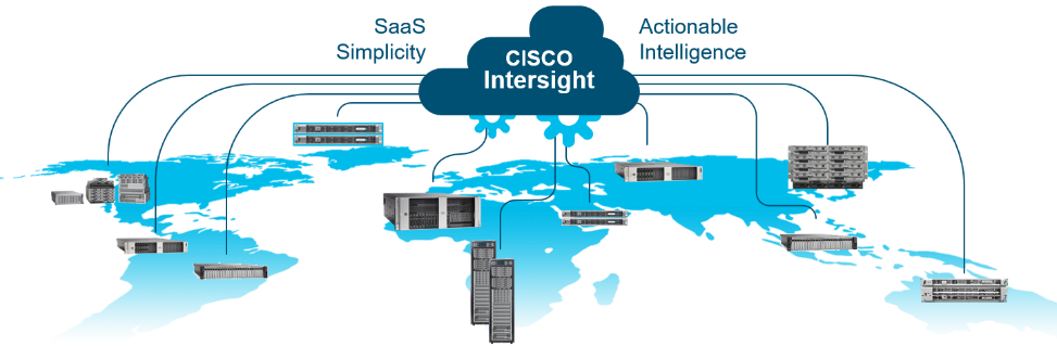
CDIP is brought together with a single pane of glass management with Cisco Intersight.
Both Big Data and machine learning technology have progressed to the point where they are being implemented in production systems running 24x7. There exists a need for a proven, dependable, high-performance platform for the ingestion, processing, storage, and analysis of the data, as well as the seamless dissemination of the output, results, and insights of the analysis.
This solution implements Cloudera Data Platform Private Cloud Base (CDP PvC Base) and Cloudera Data Platform Private Cloud Experiences (CDP PVC Experiences) on Cisco Data Intelligence Platform (CDIP) architecture, a world-class platform specifically designed for demanding workloads that is both easy to scale and easy to manage, even as the requirements grow to thousands of servers and petabytes of storage.
Many companies, recognizing the immense potential of big data and machine learning technology, are gearing up to leverage these new capabilities, building out departments and increasing hiring. However, these efforts face a new set of challenges:
● Making the data available to the diverse set of engineers (Data engineers, analysts, data scientists) who need it
● Enabling access to high-performance computing resources, GPUs, that also scale with the data growth
● Allowing people to work with the data using the environments in which they are familiar
● Publishing their results so the organization can make use of it
● Enabling the automated production of those results
● Managing the data for compliance and governance
● Scaling the system as the data grows
● Managing and administering the system in an efficient, cost-effective way
This solution is based on the Cisco Data Intelligence Platform that includes computing, storage, connectivity, capabilities built on Cisco Unified Computing System (Cisco UCS) infrastructure, using Cisco UCS C-Series and S-Series Rack Servers and unified management with Cisco Intersight to help companies manage the entire infrastructure from a single pane of glass along with Cloudera Data Platform to provide the software for fast ingest of data and managing and processing exabyte scale data being collected. This architecture is specifically designed for performance and linear scalability for big data and machine learning workload.
The intended audience of this document includes sales engineers, field consultants, professional services, IT managers, partner engineering and customers who want to deploy the Cloudera Data Platform Private Cloud Experiences on the Cisco Data Intelligence Platform (Cisco UCS M5 Rack-Mount servers).
This document describes the architecture, design choices, and deployment procedures for Cisco Data Intelligence Platform using Cloudera Data Platform Private Cloud Base and Cloudera Data Platform Private Cloud Experiences on Cisco UCS C240 M5.
This document also serves as a step-by-step guide on how to deploy Cloudera Data Platform on a 25-node cluster of Cisco UCS C240 M5 Rack Server.
This solution extends the portfolio of Cisco Data Intelligence Platform (CDIP) architecture with Cloudera Data Platform Private Cloud Experiences, a state-of-the-art platform, providing a data cloud for demanding workloads that is easy to deploy, scale and manage which is built on top of Red Hat Openshift Container Platform (RHOCP). Furthermore, as the enterprise’s requirements and needs changes overtime, the platform can grow to thousands of servers, at exabytes of storage and tens of thousands of cores to process this data.
The following will be implemented in this validated design:
● Cisco Intersight to configure and manage Cisco Infrastructure
● Data lake provided by Cloudera Data Platform Private Cloud Base on Cisco UCS servers
● Compute Farm running
◦ Red Hat OpenShift Container Platform to provide the Kubernetes and container platform for the private cloud
◦ Cloudera Data Platform Private Cloud Experiences as the application providing data processing, auto scaling and self-service onboarding of the user
In this release, we will be primarily exploring Cloudera Machine Learning as the persona to cater to data scientists. This release of Cloudera Private Cloud Experiences also includes Cloudera Data Warehouse and is not the subject of this document.
This CVD details the process of installing CDP Private Cloud Experiences including the installation of Red Hat OpenShift Container Platform 4.5, the prerequisites for CDP Private Cloud Experiences and the configuration details of the cluster.
Cisco Data Intelligence Platform
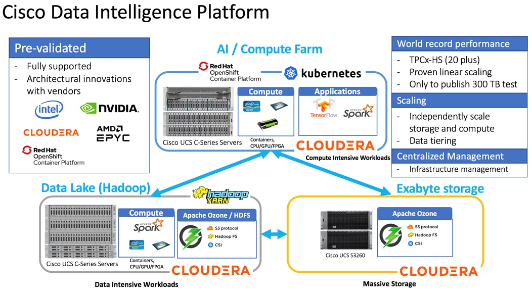
Cisco Data Intelligence Platform (CDIP) is a cloud-scale architecture which brings together big data, AI/compute farm, and storage tiers to work together as a single entity while also being able to scale independently to address the IT issues in the modern data center. This architecture provides the following:
● Extremely fast data ingest, and data engineering done at the data lake.
● AI compute farm allowing for different types of AI frameworks and compute types (GPU, CPU, FPGA) to work on this data for further analytics.
![]() GPU and FPGA are not supported in this release of Cloudera Private Cloud Experiences 1.1
GPU and FPGA are not supported in this release of Cloudera Private Cloud Experiences 1.1
● A storage tier, allowing to gradually retire data which has been worked on to a storage dense system with a lower $/TB providing a better TCO. Next-generation Apache Ozone filesystem for storage in a data lake.
● Seamlessly scale the architecture to thousands of nodes with a single pane of glass management using Cisco Intersight and Cisco Application Centric Infrastructure (ACI).
Cisco Data Intelligence Platform caters to the evolving architecture bringing together a fully scalable infrastructure with centralized management and fully supported software stack (in partnership with industry leaders in the space) to each of these three independently scalable components of the architecture including data lake, AI/ML and Object stores.
Cisco Data Intelligence Platform with Cloudera Data Platform
Cisco developed numerous industry leading Cisco Validated Designs (reference architectures) in the area of Big Data, compute farm with Kubernetes (CVD with RedHat OpenShift Container Platform) and Object store.
A CDIP architecture can be fully enabled by the Cloudera Data Platform with the following components:
● Data lake enabled through CDP PvC Base
● Private Cloud with compute on Kubernetes can be enabled through CDP Private Cloud Experiences and
● Exabyte storage enabled through Apache Ozone
Figure 1. Cisco Data Intelligent Platform with Cloudera Data Platform
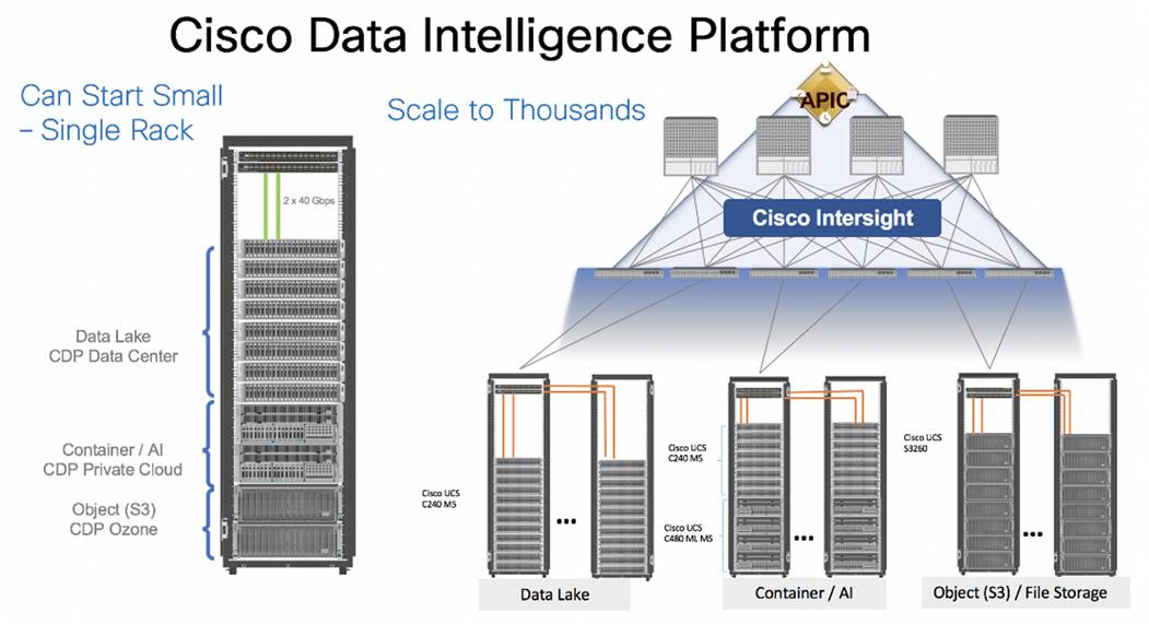
This architecture can start from a single rack and scale to thousands of nodes with a single pane of glass management with Cisco Application Centric Infrastructure (ACI).
Figure 2. Cisco Data Intelligent Platform at Scale
Cisco Data Intelligence Platform reference architectures are carefully designed, optimized, and tested with the leading big data and analytics software distributions to achieve a balance of performance and capacity to address specific application requirements. You can deploy these configurations as is or use them as templates for building custom configurations. You can scale your solution as your workloads demand, including expansion to thousands of servers through the use of Cisco Nexus 9000 Series Switches. The configurations vary in disk capacity, bandwidth, price, and performance characteristics.
Data Lake Reference Architecture
Figure 3 illustrates the data lake reference architecture.
Figure 3. Cisco UCS Integrated Infrastructure for Big Data and Analytics – Modernize Hadoop Infrastructure
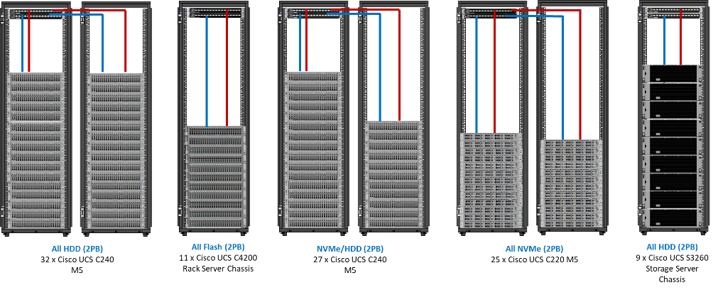
Table 1 lists the data lake, private cloud, and dense storage with Apache Ozone reference architecture for Cisco Data Intelligence Platform.
Table 1. Cisco Data Intelligence Platform Data Lake Configuration
|
|
High Performance |
Performance |
Capacity |
High Capacity |
| Servers |
16 x Cisco UCS C220 M5SN Rack Servers with small-form-factor (SFF) drives (UCSC-C220-M5SN) |
16 x Cisco UCS C240 M5 Rack Servers with small-form-factor (SFF) drives |
16 x Cisco UCS C240 M5 Rack Servers with large-form-factor (LFF) drives |
8 x Cisco UCS S3260 Storage Servers each with dual nodes and each node with the following: |
| CPU |
2 x 2nd Gen Intel® Xeon® Scalable Processors 6230R (2 x 26 cores, at 2.1 GHz) |
2 x 2nd Gen Intel® Xeon® Scalable Processors 5218R processors (2 x 20 cores, at 2.1 GHz) |
2 x 2nd Gen Intel Xeon Scalable Processors 5218R (2 x 20 cores, at 2.1 GHz) |
2 x 2nd Gen Intel Xeon Scalable Processors 6230R (2 x 26 cores, 2.1 GHz) |
| Memory |
12 x 32GB DDR4 (384 GB) |
12 x 32GB DDR4 (384 GB) |
12 x 32GB DDR4 (384 GB) |
12 x 32GB DDR4 (384 GB) |
| Boot |
M.2 with 2 x 240-GB SSDs |
M.2 with 2 x 240-GB SSDs |
M.2 with 2 x 240-GB SSDs |
2 x 240-GB SATA SSDs |
| Storage |
10 x 8TB 2.5in U.2 Intel P4510 NVMe High Perf. Value Endurance |
26 x 2.4TB 10K rpm SFF SAS HDDs or 12 x 1.6-TB Enterprise Value SATA SSDs |
12 x 8-TB 7.2K rpm LFF SAS HDDs |
28 x 4 TB 7.2K rpm LFF SAS HDDs per server node |
| Virtual interface card (VIC) |
25 Gigabit Ethernet (Cisco UCS VIC 1457) or 40/100 Gigabit Ethernet (Cisco UCS VIC 1497) |
25 Gigabit Ethernet (Cisco UCS VIC 1455) or 40/100 Gigabit Ethernet (Cisco UCS VIC 1497) |
25 Gigabit Ethernet (Cisco UCS VIC 1455) or 40/100 Gigabit Ethernet (Cisco UCS VIC 1497) |
40 Gigabit Ethernet (Cisco UCS VIC 1387) or 25 Gigabit Ethernet (Cisco UCS VIC 1455) or 40/100 Gigabit Ethernet (Cisco UCS VIC 1495) |
| Storage controller |
NVMe Switch included in the optimized server |
Cisco 12-Gbps SAS modular RAID controller with 4-GB flash-based write cache (FBWC) or Cisco 12-Gbps modular SAS host bus adapter (HBA) |
Cisco 12-Gbps SAS modular RAID controller with 2-GB FBWC or Cisco 12-Gbps modular SAS host bus adapter (HBA) |
Cisco 12-Gbps SAS Modular RAID Controller with 4-GB flash-based write cache (FBWC) |
| Network connectivity |
Cisco UCS 6332 Fabric Interconnect or Cisco UCS 6454/64108 Fabric Interconnect |
Cisco UCS 6332 Fabric Interconnect or Cisco UCS 6454/64108 Fabric Interconnect |
Cisco UCS 6332 Fabric Interconnect or Cisco UCS 6454/64108 Fabric Interconnect |
Cisco UCS 6332 Fabric Interconnect or Cisco UCS 6454/64108 Fabric Interconnect |
| GPU (optional) |
Up to 2 x NVIDIA Tesla T4 with 16 GB memory each |
Up to 2 x NVIDIA Tesla V100 with 32 GB memory each Or Up to 6 x NVIDIA Tesla T4 with 16 GB memory each |
2 x NVIDIA Tesla V100 with 32 GB memory each Or Up to 6 x NVIDIA Tesla T4 with 16 GB memory each |
|
Private Cloud Reference Architecture
Table 2 lists the CDIP private cloud configuration for master and worker nodes.
Table 2. Cisco Data Intelligence Platform Private Cloud configuration (Master and worker nodes)
|
|
High Core Option |
| Servers |
8 x Cisco UCS C240 M5 Rack Servers |
| CPU |
2 x 2nd Gen Intel Xeon Scalable Processor 6230R (2 x 26 cores, 2.1 GHz) |
| Memory |
12 x 32GB DDR4 (384 GB) |
| Boot |
M.2 with 2 x 960GB SSDs |
| Storage |
4 x 2.4TB 10K rpm SFF SAS HDDs or 4 x 1.6TB Enterprise Value SATA SSDs |
| VIC |
25 Gigabit Ethernet (Cisco UCS VIC 1457) or 40/100 Gigabit Ethernet (Cisco UCS VIC 1497) |
| Storage controller |
Cisco 12-Gbps SAS modular RAID controller with 4-GB FBWC or Cisco 12-Gbps modular SAS HBA |
| Network connectivity |
Cisco UCS 6332 Fabric Interconnect or Cisco UCS 6454 Fabric Interconnect |
| GPU (optional) |
2 x NVIDIA TESLA V100 with 32-GB memory each or up to 6 x NVIDIA T4
|
Dense Storage Apache Ozone Reference Architecture
Table 3 lists the CDIP Apache Ozone reference architecture.
Table 3. Cisco Data Intelligence Platform Apache Ozone Reference Architecture
|
|
High Capacity |
High Performance |
| Server |
Cisco UCS S3260 with Single Node |
Cisco UCS S3260 with Dual Node, each node with |
| CPU |
2 x 2nd Gen Intel Xeon Scalable Processor 6230R (2 x 26 cores, 2.1 GHz) |
2 x 2nd Gen Intel Xeon Scalable Processor 6230R (2 x 26 cores, 2.1 GHz) |
| Memory |
12 x 32GB 2666 MHz (384 GB) |
12 x 32GB 2666 MHz (192 GB) per Node |
| Boot |
2 x 1.6TB SATA Boot SSDs |
2 x 1.6TB SATA Boot SSDs |
| Storage |
48x8TB drives + 2x1.9TB 1xDWPD EV SSD |
24x16TB drives + 2x1.9TB 1xDWPD EV SSD |
| VIC |
25 Gigabit Ethernet (Cisco UCS VIC 1455) or 40/100 Gigabit Ethernet (Cisco UCS VIC 1495) |
25 Gigabit Ethernet (Cisco UCS VIC 1455) or 40/100 Gigabit Ethernet (Cisco UCS VIC 1495) |
| Storage controller |
Cisco UCS S3260 dual RAID controller |
Cisco UCS S3260 dual RAID controller |
| Network connectivity |
Cisco UCS 6332 Fabric Interconnect or Cisco UCS 6454 Fabric Interconnect |
Cisco UCS 6332 Fabric Interconnect or Cisco UCS 6454 Fabric Interconnect |
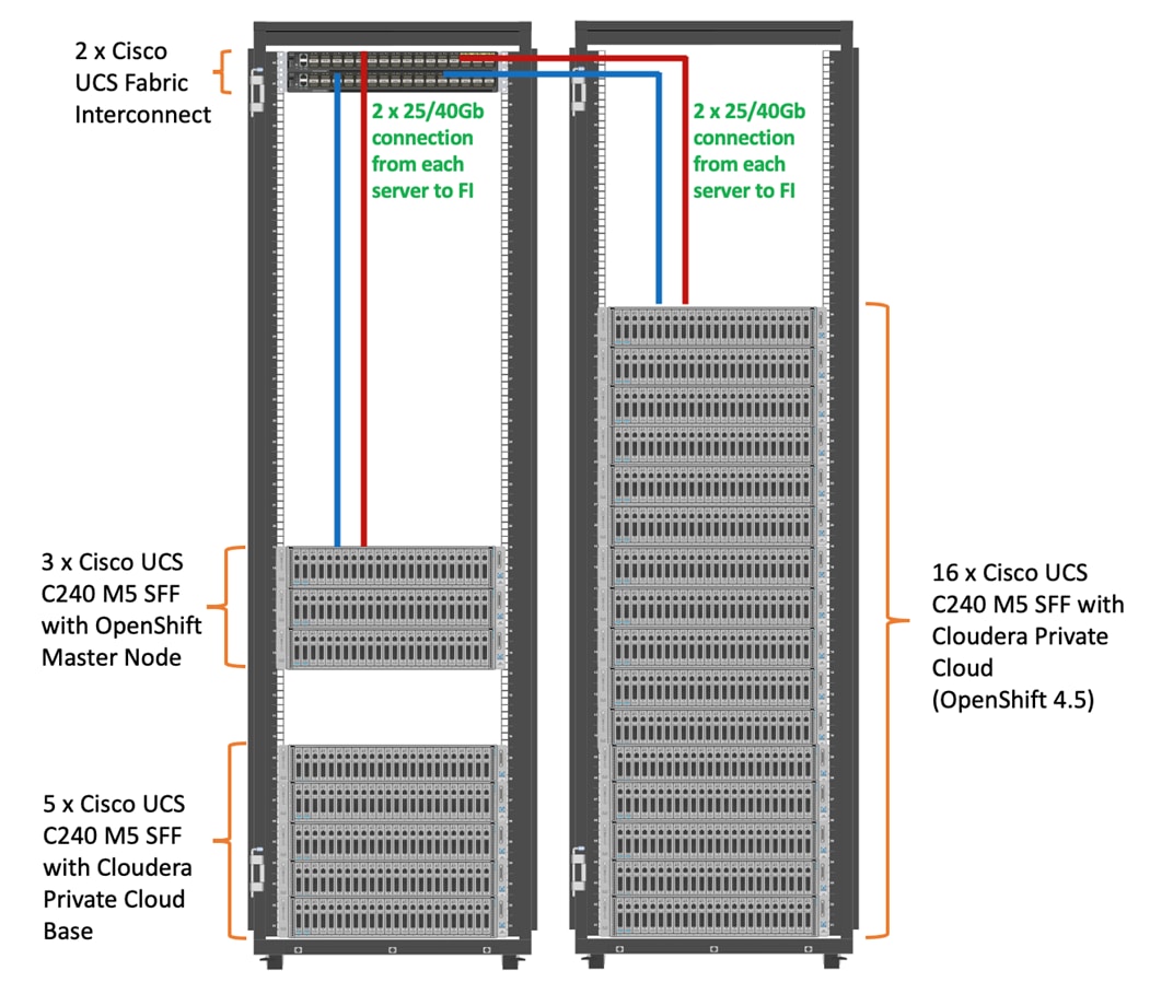
As illustrated in Figure 4, this CVD was designed with the following:
· 3 x Cisco UCS C240 M5 and RedHat OpenShift Container Platform Master nodes
· 16 x Cisco UCS C240 M5 and RedHat OpenShift Container Platform worker nodes
· 1 x Cisco UCS C240 M5 bootstrap node for RedHat OpenShift Container Platform
· 1 x Cisco UCS C240 running HA Proxy
· Cloudera Data Platform Private Cloud Base running the Cloudera manager.
Refer to http://www.cisco.com/go/bigdata_design to build a fully supported CDP Private Cloud Base on CDIP reference architecture. This CVD does not provide the details to build a CDP Private Cloud Base. For detailed instruction, click the following links:
Cisco Data Intelligence Platform with All NVMe Storage, Cisco Intersight, and Cloudera Data Platform
Cisco Data Intelligence Platform on Cisco UCS S3260 with Cloudera Data Platform
Cisco Data Intelligence Platform with Cloudera Data Platform
· 16 node cluster with Rack#1 hosting 16 Cisco UCS C240 M5 and 9 node Cisco UCS C240 M5 in Rack#2. Each link in Figure 4 represents a 40 Gigabit Ethernet link from each of the 16-server connected to a pair of Cisco Fabric Interconnect switches.
Figure 4. Cisco Data Intelligence Platform with Cloudera Data Platform Private Cloud Experiences

![]() The bootstrap controller node is not shown in the reference architecture (Figure 4). The bootstrap node is temporary and is used to deploy OpenShift control plane, once OpenShift masters are up, it can be removed.
The bootstrap controller node is not shown in the reference architecture (Figure 4). The bootstrap node is temporary and is used to deploy OpenShift control plane, once OpenShift masters are up, it can be removed.
![]() HAproxy server is used for load balancing OpenShift control and application traffic. It is recommended to use external load balancer in production environment or implement HA for HAproxy load balancers with keepalived VIP
HAproxy server is used for load balancing OpenShift control and application traffic. It is recommended to use external load balancer in production environment or implement HA for HAproxy load balancers with keepalived VIP
![]() The Cisco UCS VIC 1497 provides 40Gbps, Cisco UCS VIC 1457 provides 10/25Gbps, and the Cisco UCS VIC 1497 provides 40/100Gbps connectivity for the Cisco UCS C-series rack server. For more information see: Cisco UCS C-Series Servers Managing Network Adapters.
The Cisco UCS VIC 1497 provides 40Gbps, Cisco UCS VIC 1457 provides 10/25Gbps, and the Cisco UCS VIC 1497 provides 40/100Gbps connectivity for the Cisco UCS C-series rack server. For more information see: Cisco UCS C-Series Servers Managing Network Adapters.
Figure 5 and Figure 6 illustrates how to scale the solution. Each pair of Cisco UCS 6332 Fabric Interconnects has 24 Cisco UCS C240 M5 servers connected to it. This allows for eight uplinks from each Fabric Interconnect to the Cisco Nexus 9332 switch. Six pairs of 6332 FIs can connect to a single switch with four uplink ports each. With 24 servers per FI, a total of 144 servers can be supported. Additionally, this solution can scale to thousands of nodes with the Cisco Nexus 9500 series family of switches.
In this reference architectures, each of the components is scaled separately, and for the purposes of this example, scaling is uniform. Two scale scenarios are as follows:
· Scaled architecture with 3:1 oversubscription with Cisco fabric interconnects and Cisco ACI
· Scaled architecture with 2:1 oversubscription with Cisco ACI
In the following scenarios, the goal is to populate up to a maximum of 200 leaf nodes in a Cisco ACI domain. Not all cases reach that number because they use the Cisco Nexus 9508 Switch for this sizing and not the Cisco Nexus 9516 Switch.
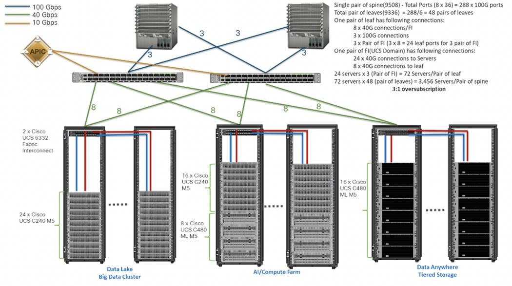
Scaled Architecture with 3:1 Oversubscription with Cisco Fabric Interconnects and Cisco ACI
The architecture discussed here and shown in Figure 5 supports 3:1 network oversubscription from every node to every other node across a multidomain cluster (nodes in a single domain within a pair of Cisco fabric interconnects are locally switched and not oversubscribed).
From the viewpoint of the data lake, 24 Cisco UCS C240 M5 Rack Servers are connected to a pair of Cisco UCS 6332 Fabric Interconnects (with 24 x 40-Gbps throughput). From each fabric interconnect, 8 x 40-Gbps links connect to a pair of Cisco Nexus 9336 Switches. Three pairs of fabric interconnects can connect to a single pair of Cisco Nexus 9336 Switches (8 x 40-Gbps links per Fabric Interconnect to a pair of Cisco Nexus switches). Each of these Cisco Nexus 9336 Switches connects to a pair of Cisco Nexus 9508 Cisco ACI switches with 6 x 100-Gbps uplinks (connecting to a Cisco N9K-X9736C-FX line card). the Cisco Nexus 9508 Switch with the Cisco N9K-X9736C-FX line card can support up to 36 x 100-Gbps ports, each and 8 such line cards.
Figure 5. Scaled Architecture with 3:1 Oversubscription with Cisco Fabric Interconnects and Cisco ACI
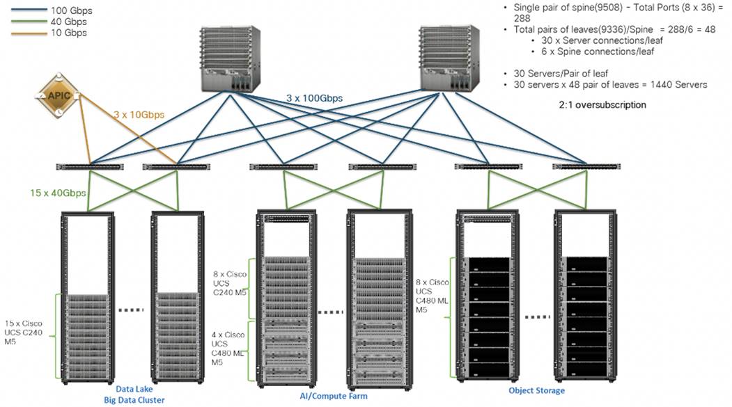
Scaled Architecture with 2:1 Oversubscription with Cisco ACI
In this scenario and shown in Figure 6, the Cisco Nexus 9508 Switch with the Cisco N9K-X9736C-FX line card can support up to 36 x 100-Gbps ports, each and 8 such line cards.
For the 2:1 oversubscription, 30 Cisco UCS C240 M5 Rack Servers are connected to a pair of Cisco Nexus 9336 Switches, and each Cisco Nexus 9336 connects to a pair of Cisco Nexus 9508 Switches with three uplinks each. A pair of Cisco Nexus 9336 Switches can support 30 servers and connect to a spine with 6 x 100-Gbps links on each spine. This single pod (pair of Cisco Nexus 9336 Switches connecting to 30 Cisco UCS C240 M5 servers and 6 uplinks to each spine) can be repeated 48 times (288/6) for a given Cisco Nexus 9508 Switch and can support up to1440 servers.
To reduce the oversubscription ratio (to get 1:1 network subscription from any node to any node), you can use just 15 servers under a pair of Cisco Nexus 9336 Switches and then move to Cisco Nexus 9516 Switches (the number of leaf nodes would double).
To scale beyond this number, multiple spines can be aggregated.
Figure 6. Scaled Architecture with 2:1 Oversubscription with Cisco ACI
![]() In a 5-rack system, 80% of traffic is expected to go upstream.
In a 5-rack system, 80% of traffic is expected to go upstream.
Cisco Data Intelligence Platform
This section describes the components used to build Cisco Data Intelligence Platform, a highly scalable architecture designed to meet a variety of scale-out application demands with seamless data integration and management integration capabilities.
Cisco Data Intelligence Platform powered by Cloudera Data Platform delivers:
● Latest generation of CPUs from Intel (2nd generation Intel Scalable family, with Cascade Lake CLXR).
● Cloud scale and fully modular architecture where big data, AI/compute farm, and massive storage tiers work together as a single entity and each CDIP component can also scale independently to address the IT issues in the modern data center.
● World record Hadoop performance both for MapReduce and Spark frameworks published at TPCx-HS benchmark.
● AI compute farm offers different types of AI frameworks and compute types (GPU, CPU, FPGA) to work data for analytics.
● A massive storage tier enables to gradually retire data and quick retrieval when needed on a storage dense sub-systems with a lower $/TB providing a better TCO.
● Data compression with FPGA, offload compute-heavy compression tasks to FPGA, relieve CPU to perform other tasks, and gain significant performance.
● Seamlessly scale the architecture to thousands of nodes.
● Single pane of glass management with Cisco Intersight.
● ISV Partner ecosystem – Top notch ISV partner ecosystem, offering best of the breed end-to-end validated architectures.
● Pre-validated and fully supported platform.
● Disaggregate Architecture supports separation of storage and compute for a data lake.
● Container Cloud, Kubernetes, compute farm backed by the industry leading container orchestration engine and offers the very first container cloud plugged with data lake and object store.
Containerization
Hadoop 3.0 introduced production-ready Docker container support on YARN with GPU isolation and scheduling. This opened up plethora of opportunities for modern applications, such as micro-services and distributed applications frameworks comprised of 1000s of containers to execute AI/ML algorithms on peta bytes of data with ease and in a speedy fashion.
Distributed Deep Learning with Apache Submarine
Hadoop community initiated the Apache Submarine project to make distributed deep learning/machine learning applications easily launched, managed, and monitored. These improvements make distributed deep learning/machine learning applications (such as TensorFlow) run on Apache Hadoop YARN, Kubernetes, or just a container service. It enables data scientists to focus on algorithms instead of worrying about underlying infrastructure. Apache Submarine Workbench (work in progress) is a WEB system for data scientists where they can interactively access notebooks, submit/manage jobs, manage models, create model training workflows, access data sets, and more.
Apache Spark 3.0
Apache Spark 3.0 is a highly-anticipated release. To meet this expectation, Spark is no longer limited just to CPU for its workload, it now offers GPU isolation and pooling GPUs from different servers to accelerated compute. To easily manage the deep learning environment, YARN launches the Spark 3.0 applications with GPU. This prepares the other workloads, such as Machine Learning and ETL, to be accelerated by GPU for Spark Workloads. Cisco Blog on Apache Spark 3.0
Cloudera Data Platform – Private Cloud Base (PvC)
With the merger of Cloudera and Hortonworks, a new “Cloudera” software named Cloudera Data Platform (CDP) combined the best of Hortonwork’s and Cloudera’s technologies to deliver the industry leading first enterprise data cloud. CDP Private Cloud Base is the on-prem version of CDP and CDP Private Cloud Experiences is the on-prem version of Private Cloud to enable compute on Kubernetes with Redhat Openshift Container Platform. This unified distribution is a scalable and customizable platform where workloads can be securely provisioned. CDP gives a clear path for extending or refreshing your existing HDP and CDH deployments and set the stage for cloud-native architecture.
Cloudera Data Platform Private Cloud Experiences
Shadow IT can now be eliminated when the CDP Private Cloud is implemented in Cisco Data Intelligence Platform. CDP Private Cloud offers cloud-like experience in customer’s on-prem environment. With disaggregated compute and storage, complete self-service analytics environment can be implemented, thereby, offering better infrastructure utilization.
Also, CDP Private Cloud offers the persona’s Data Scientist, Data Engineer, and Data Analyst, thus providing the right tools to the user improving time-to-value.
Red Hat OpenShift Container Platform (RHOCP) Cluster
Cloudera has selected Red Hat OpenShift as the preferred container platform for CDP Private Cloud. With Red Hat OpenShift, CDP Private Cloud delivers powerful, self-service analytics and enterprise-grade performance with the granular security and governance policies that IT leaders demand.
To keep pace in the digital era, businesses must modernize their data strategy for increased agility, ease-of-use, and efficiency. Together, Red Hat OpenShift and CDP Private Cloud help create an essential hybrid, multi-cloud data architecture, enabling teams to rapidly onboard mission-critical applications and run them anywhere, without disrupting existing ones.
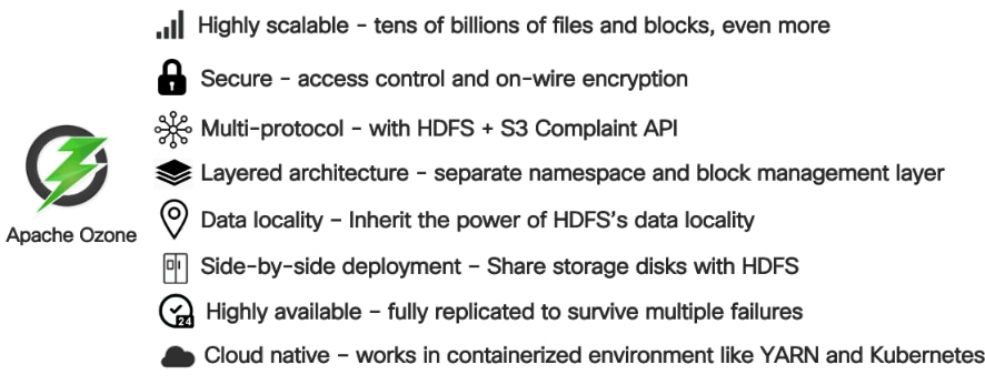
Apache Ozone Object Store
Apache Ozone is a scalable, redundant, and distributed object store for Hadoop. Apart from scaling to billions of objects of varying sizes, Ozone can function effectively in containerized environments such as Kubernetes and YARN. Applications using frameworks like Apache Spark, YARN and Hive work natively without any modifications. Ozone is built on a highly available, replicated block storage layer called Hadoop Distributed Data Store (HDDS).
Ozone is a scale-out architecture with minimal operational overheads and long-term maintenance efforts. Ozone can be co-located with HDFS with single security and governance policies for easy data exchange or migration and also offers seamless application portability. Ozone enables separation of compute and storage via the S3 API as well as similar to HDFS, it also supports data locality for applications that choose to use it.
The design of Ozone was guided by the following key principles:
Figure 7. Ozone Design Principle
Kubernetes
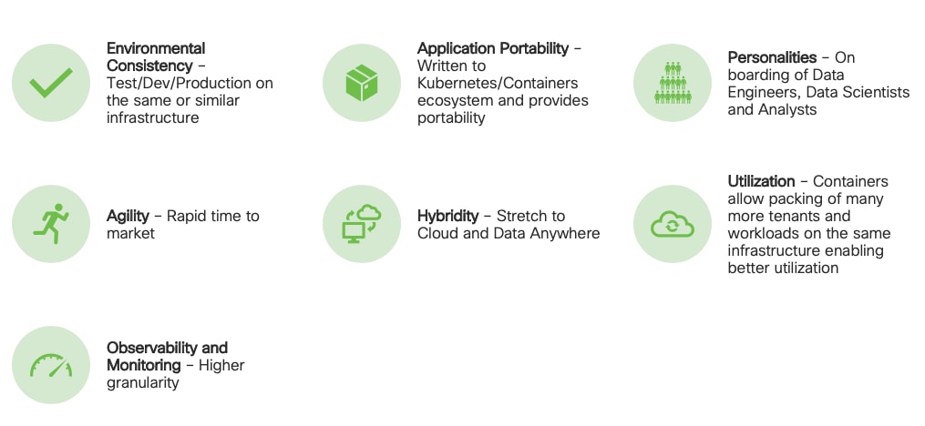
Extracting intelligence from data lake in a timely and speedy fashion is an absolute necessity in finding emerging business opportunities, accelerating time to market efforts, gaining market share, and by all means, increasing overall business agility.
In today’s fast-paced digitization, Kubernetes enables enterprises to rapidly deploy new updates and features at scale while maintaining environmental consistency across test/dev/prod. Kubernetes provides the foundation for cloud-native apps which can be packaged in container images and can be ported to diverse platforms. Containers with microservice architecture managed and orchestrated by Kubernetes help organizations embark on a modern development pattern. Moreover, Kubernetes has become in fact, the standard for container orchestration and offers the core for on-prem container cloud for enterprises. it's a single cloud-agnostic infrastructure with a rich open-source ecosystem. It allocates, isolates, and manages resources across many tenants at scale as needed in elastic fashion, thereby, giving efficient infrastructure resource utilization. Figure 8 illustrates how Kubernetes is transforming the use of compute and becoming the standard for running applications.
Figure 8. Compute on Kubernetes is exciting!!!
Spark on Kubernetes
With Spark 2.4.5 along with YARN as a scheduler, comes full support for Apache Spark on Kubernetes as a scheduler. This enables a Kubernetes cluster act as compute layer running Spark workloads for the data lake much of which is used in Cloudera Private Cloud applications.
Spark on Kubernetes has considerably advanced the Hadoop ecosystem, since it made is easier for many public cloud-specific applications and framework use cases to be deployed on-prem; thus, providing hybridity to stretch to cloud anywhere. Kubernetes address gaps that existed in YARN such as lack of isolation and reproducibility and allows workloads to be packaged in docker images. Spark on Kubernetes also inherit all other in-built features such as auto-scaling, detailed metrics, advanced container networking, security, and so on.
Hybrid Architecture
Red Hat OpenShift, being the preferred container cloud platform for CDP private cloud and so is for CDIP, is the market leading Kubernetes powered container platform. This combination is the first enterprise data cloud with a powerful hybrid architecture that decouples compute and storage for greater agility, ease-of-use, and more efficient use of private and multi-cloud infrastructure resources. With Cloudera’s Shared Data Experience (SDX), security and governance policies can be easily and consistently enforced across data and analytics in private as well as multi-cloud deployments. This hybridity will open myriad opportunities for multi-function integration with other frameworks such as streaming data, batch workloads, analytics, data pipelining/engineering, and machine learning.
Cloud Native Architecture for Data Lake and AI
Cisco Data Intelligence Platform with CDP private cloud accelerates the process of becoming cloud-native for your data lake and AI/ML workloads. By leveraging Kubernetes powered container cloud, enterprises can now quickly break the silos in monolithic application frameworks and embrace a continuous innovation of micro-services architecture with CI/CD approach. With cloud-native ecosystem, enterprises can build scalable and elastic modern applications that extends the boundaries from private cloud to hybrid.
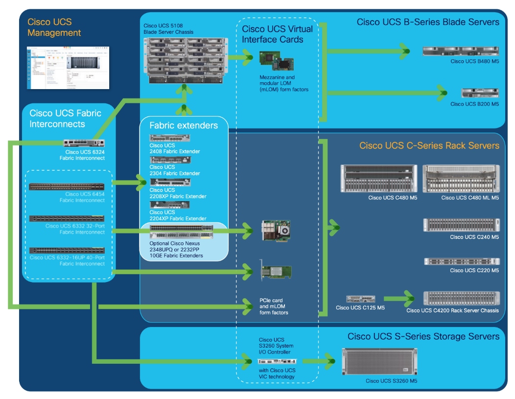
Cisco Unified Computing System
Cisco Unified Computing System™ (Cisco UCS®) is a next-generation data center platform that unites computing, networking, storage access, and virtualization resources into a cohesive system designed to reduce Total Cost of Ownership (TCO) and increase business agility. The system integrates a low-latency, lossless 10/25/40/100 Gigabit Ethernet unified network fabric with enterprise-class, x86-architecture servers. The system is an integrated, scalable, multi-chassis platform in which all resources participate in a unified management domain (Figure 9).
Figure 9. Cisco UCS Component Hierarchy
Cisco Intersight is Cisco’s systems management platform that delivers intuitive computing through cloud-powered intelligence. This platform offers a more intelligent level of management that enables IT organizations to analyze, simplify, and automate their environments in ways that were not possible with prior generations of tools. This capability empowers organizations to achieve significant savings in Total Cost of Ownership (TCO) and to deliver applications faster, so they can support new business initiatives.
Cisco Intersight is a Software as a Service (SaaS) infrastructure management which provides a single pane of glass management of CDIP infrastructure in the data center. Cisco Intersight scales easily, and frequent updates are implemented without impact to operations. Cisco Intersight Essentials enables customers to centralize configuration management through a unified policy engine, determine compliance with the Cisco UCS Hardware Compatibility List (HCL), and initiate firmware updates. Enhanced capabilities and tight integration with Cisco TAC enables more efficient support. Cisco Intersight automates uploading files to speed troubleshooting. The Intersight recommendation engine provides actionable intelligence for IT operations management. The insights are driven by expert systems and best practices from Cisco.
Cisco Intersight offers flexible deployment either as Software as a Service (SaaS) on Intersight.com or running on your premises with the Cisco Intersight virtual appliance. The virtual appliance provides users with the benefits of Cisco Intersight while allowing more flexibility for those with additional data locality and security requirements.
Cisco Intersight has the following:
● Connected TAC
● Security Advisories
● Hardware Compatibility List (HCL) and much more
To learn more about all the features of Intersight, go to: https://www.cisco.com/c/en/us/products/servers-unified-computing/intersight/index.html
Cisco UCS Manager (UCSM) resides within the Cisco UCS Fabric Interconnect. It makes the system self-aware and self-integrating, managing all the system components as a single logical entity. Cisco UCS Manager can be accessed through an intuitive graphical user interface (GUI), a command-line interface (CLI), or an XML application-programming interface (API). Cisco UCS Manager uses service profiles to define the personality, configuration, and connectivity of all resources within Cisco UCS, radically simplifying provisioning of resources so that the process takes minutes instead of days. This simplification allows IT departments to shift their focus from constant maintenance to strategic business initiatives.
Key Features
● Supports Cisco UCS B-Series Blade and Cisco UCS C-Series Rack Servers, the Cisco UCS C3260 storage server, Cisco UCS Mini, and the Cisco HyperFlex hyperconverged infrastructure.
● Programmatically controls server, network, and storage resources, with a unified, policy-driven management, so they can be efficiently managed at scale through software.
● Works with HTML 5, Java, or CLI graphical user interfaces.
● Can automatically detect, inventory, manage, and provision system components that are added or changed.
● Facilitates integration with third-party systems management tools.
● Builds on existing skills and supports collaboration across disciplines through role-based administration.
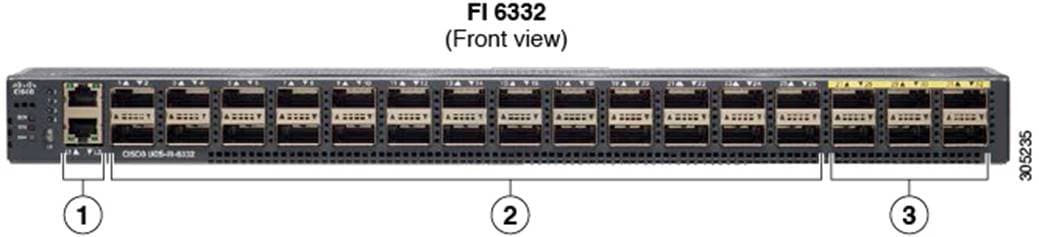
Cisco UCS 6300 Series Fabric Interconnects
Cisco UCS 6300 Series Fabric Interconnects provide high-bandwidth, low-latency connectivity for servers, with integrated, unified management provided for all connected devices by Cisco UCS Manager. Deployed in redundant pairs, Cisco fabric interconnects offer the full active-active redundancy, performance, and exceptional scalability needed to support the large number of nodes that are typical in clusters serving big data applications. Cisco UCS Manager enables rapid and consistent server configuration using service profiles, automating ongoing system maintenance activities such as firmware updates across the entire cluster as a single operation. Cisco UCS Manager also offers advanced monitoring with options to raise alarms and send notifications about the health of the entire cluster.
The Cisco UCS 6300 Series Fabric Interconnects are a core part of Cisco UCS, providing low-latency, lossless 10 and 40 Gigabit Ethernet, Fiber Channel over Ethernet (FCoE), and Fiber Channel functions with management capabilities for the entire system. All servers attached to Fabric interconnects become part of a single, highly available management domain.
Figure 11. Cisco UCS 6332UP 32 -Port Fabric Interconnect
For more information, go to: https://www.cisco.com/c/en/us/products/collateral/servers-unified-computing/ucs-6300-series-fabric-interconnects/datasheet-c78-736682.html?cachemode=refresh
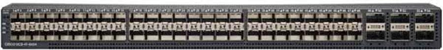
Cisco UCS 6400 Series Fabric Interconnect
The Cisco UCS 6400 Series Fabric Interconnects are a core part of the Cisco Unified Computing System, providing both network connectivity and management capabilities for the system. The Cisco UCS 6400 Series offer line-rate, low-latency, lossless 10/25/40/100 Gigabit Ethernet, Fibre Channel over Ethernet (FCoE), and Fibre Channel functions. (Figure 12 and Figure 13).
The Cisco UCS 6454 54-Port Fabric Interconnect (Figure 13) is a One-Rack-Unit (1RU) 10/25/40/100 Gigabit Ethernet, FCoE, and Fibre Channel switch offering up to 3.82 Tbps throughput and up to 54 ports. The switch has 28 10/25-Gbps Ethernet ports, 4 1/10/25- Gbps Ethernet ports, 6 40/100-Gbps Ethernet uplink ports, and 16 unified ports that can support 10/25-Gbps Ethernet ports or 8/16/32-Gbps Fibre Channel ports. All Ethernet ports are capable of supporting FCoE.
Figure 12. Cisco UCS 6454 Fabric Interconnect
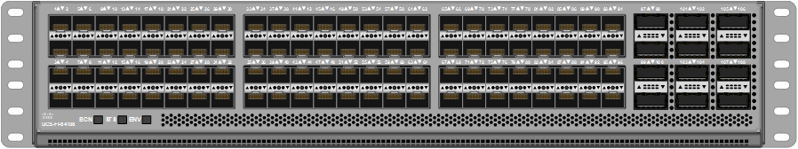
The Cisco UCS 64108 Fabric Interconnect (Figure 13) is a 2-RU top-of-rack switch that mounts in a standard 19-inch rack such as the Cisco R Series rack. The 64108 is a 10/25/40/100 Gigabit Ethernet, FCoE and Fiber Channel switch offering up to 7.42 Tbps throughput and up to 108 ports. The switch has 16 unified ports (port numbers 1-16) that can support 10/25-Gbps SFP28 Ethernet ports or 8/16/32-Gbps Fibre Channel ports, 72 10/25-Gbps Ethernet SFP28 ports (port numbers 17-88), 8 1/10/25-Gbps Ethernet SFP28 ports (port numbers 89-96), and 12 40/100-Gbps Ethernet QSFP28 uplink ports (port numbers 97-108). All Ethernet ports are capable of supporting FCoE.
Figure 13. Cisco UCS 64108 Fabric Interconnect
Cisco UCS C-Series Rack-Mount Servers
Cisco UCS C-Series Rack-Mount Servers keep pace with Intel Xeon processor innovation by offering the latest processors with increased processor frequency and improved security and availability features. With the increased performance provided by the Intel Xeon Scalable Family Processors, Cisco UCS C-Series servers offer an improved price-to-performance ratio. They also extend Cisco UCS innovations to an industry-standard rack-mount form factor, including a standards-based unified network fabric, Cisco VN-Link virtualization support, and Cisco Extended Memory Technology.
It is designed to operate both in standalone environments and as part of Cisco UCS managed configuration, these servers enable organizations to deploy systems incrementally—using as many or as few servers as needed—on a schedule that best meets the organization’s timing and budget. Cisco UCS C-Series servers offer investment protection through the capability to deploy them either as standalone servers or as part of Cisco UCS. One compelling reason that many organizations prefer rack-mount servers is the wide range of I/O options available in the form of PCIe adapters. Cisco UCS C-Series servers support a broad range of I/O options, including interfaces supported by Cisco and adapters from third parties.
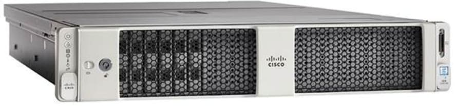
Cisco UCS C240 M5 Rack-Mount Server
The Cisco UCS C240 M5 Rack-Mount Server (Figure 14) is a 2-socket, 2-Rack-Unit (2RU) rack server offering industry-leading performance and expandability. It supports a wide range of storage and I/O-intensive infrastructure workloads, from big data and analytics to collaboration. Cisco UCS C-Series Rack Servers can be deployed as standalone servers or as part of a Cisco Unified Computing System (Cisco UCS) managed environment to take advantage of Cisco’s standards-based unified computing innovations that help reduce customers’ Total Cost of Ownership (TCO) and increase their business agility.
In response to the ever-increasing computing and data-intensive real-time workloads, the enterprise-class Cisco UCS C240 M5 server extends the capabilities of the Cisco UCS portfolio in a 2RU form factor. It incorporates the 2nd generation Intel® Xeon® Scalable and Intel® Xeon® Scalable processors, supporting up to 20 percent more cores per socket, twice the memory capacity, and five times more Non-Volatile Memory Express (NVMe) PCI Express (PCIe) Solid-State Disks (SSDs) compared to the previous generation of servers. These improvements deliver significant performance and efficiency gains that will improve your application performance. The Cisco UCS C240 M5 delivers outstanding levels of storage expandability with exceptional performance, along with the following:
● Latest Intel Xeon Scalable CPUs with up to 28 cores per socket
● Up to 24 DDR4 DIMMs for improved performance
● Up to 26 hot-swappable Small-Form-Factor (SFF) 2.5-inch drives, including 2 rear hot-swappable SFF drives (up to 10 support NVMe PCIe SSDs on the NVMe-optimized chassis version), or 12 Large-Form- Factor (LFF) 3.5-inch drives plus 2 rear hot-swappable SFF drives
● Support for 12-Gbps SAS modular RAID controller in a dedicated slot, leaving the remaining PCIe Generation 3.0 slots available for other expansion cards
● Modular LAN-On-Motherboard (mLOM) slot that can be used to install a Cisco UCS Virtual Interface Card (VIC) without consuming a PCIe slot, supporting dual 10- or 40-Gbps network connectivity
● Dual embedded Intel x550 10GBASE-T LAN-On-Motherboard (LOM) ports
● Modular M.2 or Secure Digital (SD) cards that can be used for boot
Figure 14. Cisco UCS C240 M5 Rack-Mount Server
Cisco UCS S3260 Storage Servers
The Cisco UCS S3260 Storage Server is a modular storage server with dual M5 server nodes and is optimized to deliver efficient, industry-leading storage for data-intensive workloads. The Cisco UCS S3260 server with dual-node capability that is based on the 2nd Gen Intel® Xeon® Scalable and Intel® Xeon® Scalable processors, the server features up to 840 TB of local storage in a compact 4-Rack-Unit (4RU) form factor. The drives can be configured with enterprise-class Redundant Array of Independent Disks (RAID) redundancy or with a pass-through Host Bus Adapter (HBA) controller. Network connectivity is provided with dual-port 40-Gbps nodes in each server, with expanded unified I/O capabilities for data migration between Network-Attached Storage (NAS) and SAN environments. This storage-optimized server comfortably fits in a standard 32-inch-depth rack, such as the Cisco® R 42610 Rack.
Figure 15. Cisco UCS S3260 Storage Server
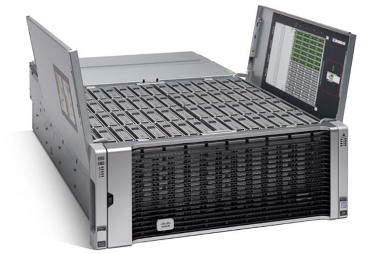
The Cisco UCS S3260 Storage Server chassis has 56 top-load LFF HDDs option as shown above with a maximum capacity of 4 TB per HDD and can be mixed with up to 28 SSDs.
The modular Cisco UCS S3260 Storage Server chassis offers flexibility with more computing, storage, and PCIe expansion on the second slot in the chassis. This second slot can be used for:
· An additional server node
· Four additional LFF HDDs with up to 10 TB capacity per HDD
· New PCIe expansion tray with up to two x8 half-height, half-width PCIe slots that can use any industry-standard PCIe card including Fibre Channel and Ethernet cards
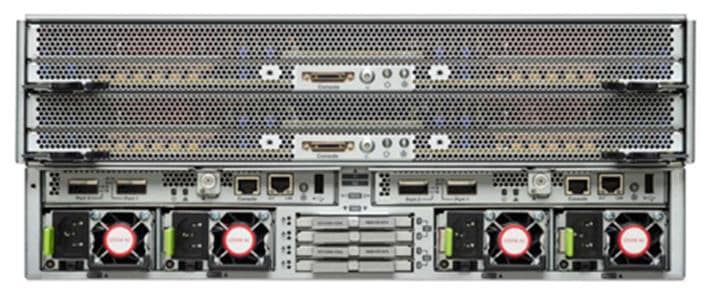
The Cisco UCS S3260 Storage Server Chassis includes a Cisco UCS Virtual Interface Card (VIC) 1300 platform chip onboard the system I/O controller, offering high-performance bandwidth with dual-port 40 Gigabit Ethernet and FCoE interfaces per system I/O controller.
Figure 16. Cisco UCS S3260 Storage Server: Rear View
Cisco UCS Virtual Interface Cards (VICs)
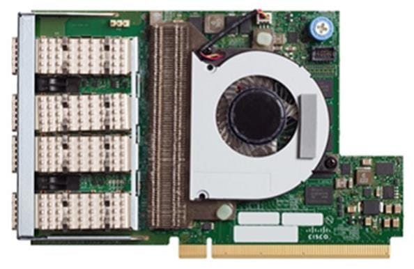
Cisco UCS VIC 1387
Cisco UCS Virtual Interface Cards (VIC) are unique to Cisco. Cisco UCS Virtual Interface Cards incorporate next-generation converged network adapter (CNA) technology from Cisco and offer dual 10- and 40-Gbps ports designed for use with Cisco UCS servers. Optimized for virtualized networking, these cards deliver high performance and bandwidth utilization, and support up to 256 virtual devices.
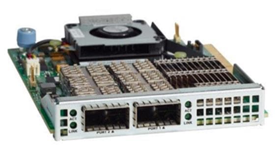
The Cisco UCS Virtual Interface Card 1387 (Figure 17) offers dual-port Enhanced Quad Small Form-Factor Pluggable (QSFP+) 40 Gigabit Ethernet and Fiber Channel over Ethernet (FCoE) in a modular-LAN-on-motherboard (mLOM) form factor. The mLOM slot can be used to install a Cisco VIC without consuming a PCIe slot providing greater I/O expandability.
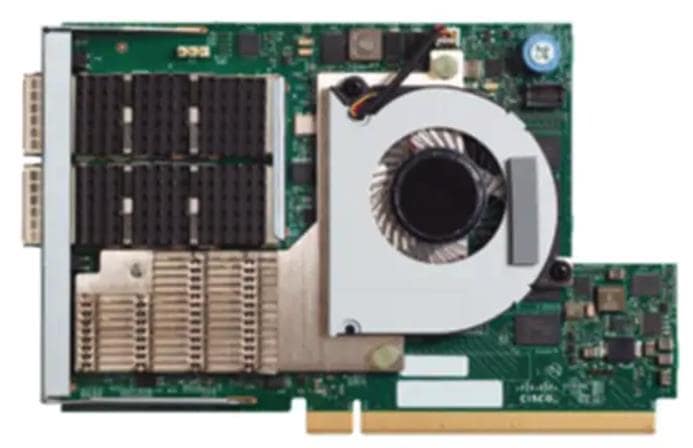
Cisco UCS VIC 1457
The Cisco UCS VIC 1457 (Figure 18) is a quad-port Small Form-Factor Pluggable (SFP28) mLOM card designed for the M5 generation of Cisco UCS C-Series Rack Servers. The card supports 10/25-Gbps Ethernet or FCoE. The card can present PCIe standards-compliant interfaces to the host, and these can be dynamically configured as either NICs or HBAs.
The Cisco VIC 1497 (Figure 19) is a dual-port Small Form-Factor (QSFP28) mLOM card designed for the M5 generation of Cisco UCS C-Series Rack Servers. The card supports 40/100-Gbps Ethernet and FCoE. The card can present PCIe standards-compliant interfaces to the host, and these can be dynamically configured as NICs and HBAs.
Cisco Intersight is Cisco’s systems management platform that delivers intuitive computing through cloud-powered intelligence. This platform offers a more intelligent level of management that enables IT organizations to analyze, simplify, and automate their environments in ways that were not possible with prior generations of tools. This capability empowers organizations to achieve significant savings in Total Cost of Ownership (TCO) and to deliver applications faster, so they can support new business initiatives.
Cisco Intersight is a Software as a Service (SaaS) infrastructure management which provides a single pane of glass management of CDIP infrastructure in the data center. Cisco Intersight scales easily, and frequent updates are implemented without impact to operations. Cisco Intersight Essentials enables customers to centralize configuration management through a unified policy engine, determine compliance with the Cisco UCS Hardware Compatibility List (HCL), and initiate firmware updates. Enhanced capabilities and tight integration with Cisco TAC enables more efficient support. Cisco Intersight automates uploading files to speed troubleshooting. The Intersight recommendation engine provides actionable intelligence for IT operations management. The insights are driven by expert systems and best practices from Cisco.
Cisco Intersight offers flexible deployment either as Software as a Service (SaaS) on Intersight.com or running on your premises with the Cisco Intersight virtual appliance. The virtual appliance provides users with the benefits of Cisco Intersight while allowing more flexibility for those with additional data locality and security requirements.
Cisco Intersight provides the following features for ease of operations and administration for the IT staff:
· Connected TAC
· Security Advisories
· Hardware Compatibility List (HCL)
To learn more about all the features of Cisco Intersight, go to: https://www.cisco.com/c/en/us/products/servers-unified-computing/intersight/index.html
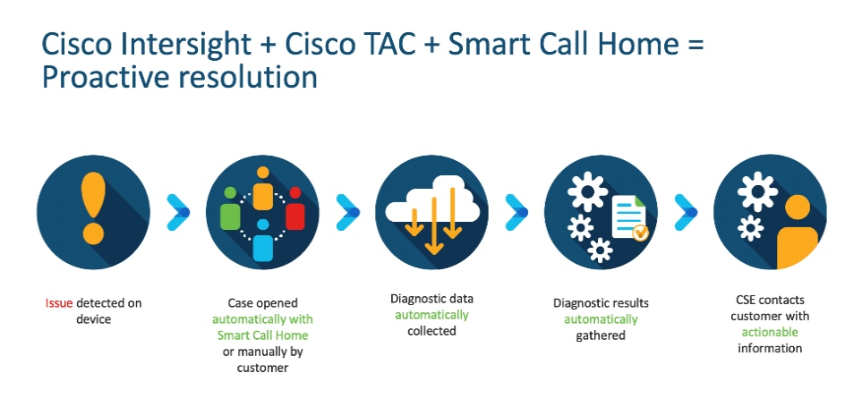
Connected TAC is an automated transmission of technical support files to the Cisco Technical Assistance Center (TAC) for accelerated troubleshooting.
Cisco Intersight enables Cisco TAC to automatically generate and upload Tech Support Diagnostic files when a Service Request is opened. If you have devices that are connected to Intersight but not claimed, Cisco TAC can only check the connection status and will not be permitted to generate Tech Support files. When enabled, this feature works in conjunction with the Smart Call Home service and with an appropriate service contract. Devices that are configured with Smart Call Home and claimed in Intersight can use Smart Call Home to open a Service Request and have Intersight collect Tech Support diagnostic files.
Figure 20. Cisco Intersight: Connected TAC
To enable Connected TAC, follow these steps:
1. Log into Intersight.com
2. Click the Servers tab. Go to Server > Actions tab. From the drop-down list, click Open TAC Case.
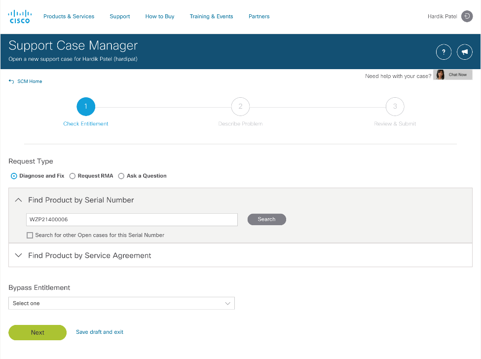
3. Clicking “Open TAC Case” launches the Cisco URL for the support case manager where associated service contracts for Server or Fabric Interconnect is displayed.
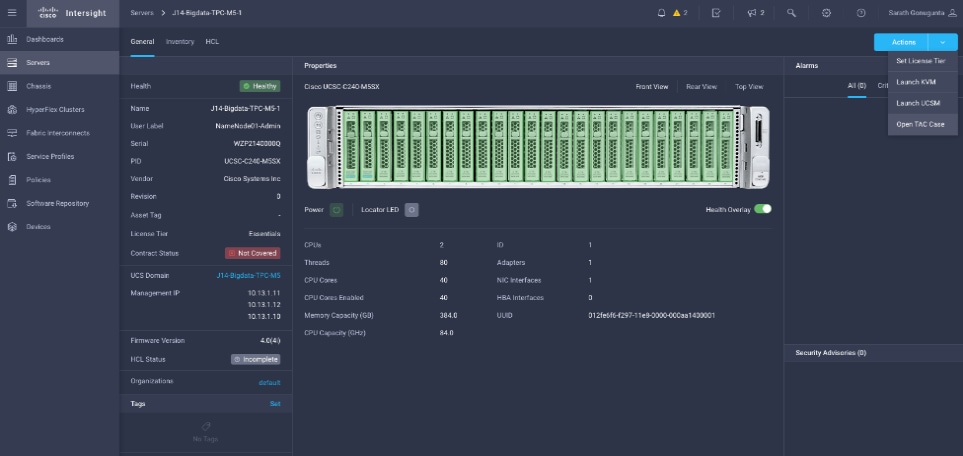
4. Click Continue.
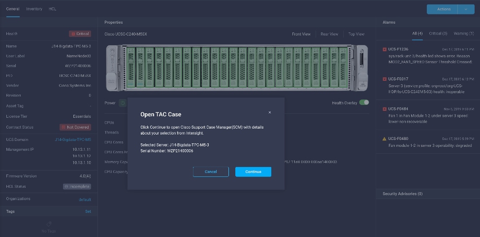
5. Follow the procedure to Open TAC Case.
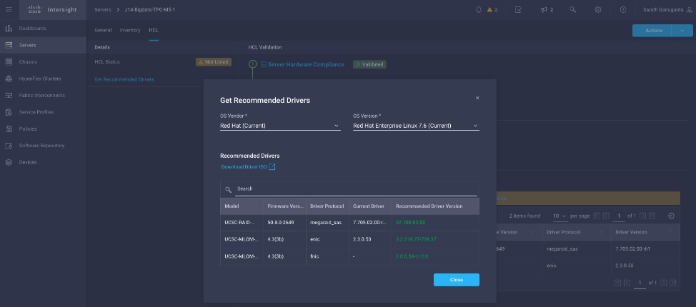
Cisco Intersight Integration for HCL
Cisco Intersight evaluates the compatibility of your Cisco UCS and Cisco HyperFlex systems to check if the hardware and software have been tested and validated by Cisco or Cisco partners. Cisco Intersight reports validation issues after checking the compatibility of the server model, processor, firmware, adapters, operating system, and drivers, and displays the compliance status with the Hardware Compatibility List (HCL).
You can use Cisco UCS Tools, a host utility vSphere Installation Bundle (VIB), or OS Discovery Tool, an open source script to collect OS and driver information to evaluate HCL compliance.
In Cisco Intersight, you can view the HCL compliance status in the dashboard (as a widget), the Servers table view, and the Server details page.
![]() For more information, go to: https://www.intersight.com/help/features#compliance_with_hardware_compatibility_list_(hcl)
For more information, go to: https://www.intersight.com/help/features#compliance_with_hardware_compatibility_list_(hcl)
Figure 21. Example of HCL Status and Driver Recommendation for RHEL 7.8
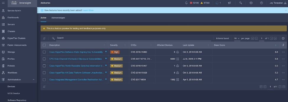
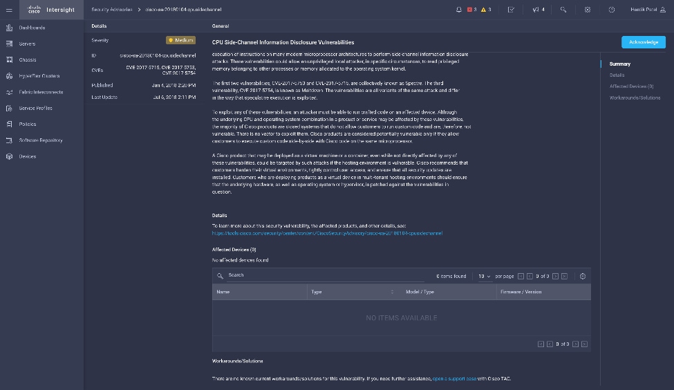
Cisco Intersight sources critical security advisories from the Cisco Security Advisory service to alert users about the endpoint devices that are impacted by the advisories and deferrals. These alerts are displayed as Advisories in Intersight. The Cisco Security Advisory service identifies and monitors and updates the status of the advisories to provide the latest information on the impacted devices, the severity of the advisory, the impacted products, and any available workarounds. If there are no known workarounds, you can open a support case with Cisco TAC for further assistance. A list of the security advisories is shown in Intersight under Advisories.
Figure 22. Intersight Dashboard
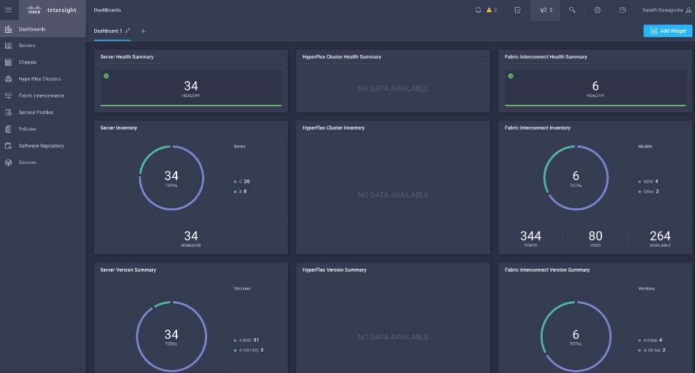
Figure 23. Example: List of PSIRTs Associated with Sample Cisco Intersight Account
CDP is an integrated data platform that is easy to deploy, manage, and use. By simplifying operations, CDP reduces the time to onboard new use cases across the organization. It uses machine learning to intelligently auto scale workloads up and down for more cost-effective use of cloud infrastructure.
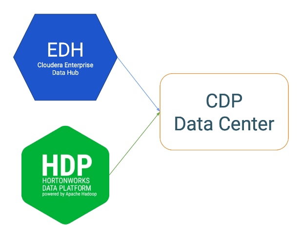
Cloudera Data Platform (CDP) Data Center is the on-premises version of Cloudera Data Platform. This new product combines the best of both worlds such as Cloudera Enterprise Data Hub and Hortonworks Data Platform Enterprise along with new features and enhancements across the stack. This unified distribution is a scalable and customizable platform where you can securely run many types of workloads.
Figure 24. Cloudera Data Platform – Unity Release
Cloudera Data Platform provides:
● Unified Distribution: Whether you are coming from CDH or HDP, CDP caters both. It offers richer feature sets and bug fixes with concentrated development and higher velocity.
● Hybrid & On-prem: Hybrid and multi-cloud experience, on-prem it offers best performance, cost, and security. It is designed for data centers with optimal infrastructure.
● Management: It provides consistent management and control points for deployments.
● Consistency: Security and governance policies can be configured once and applied across all data and workloads.
● Portability: Policies stickiness with data, even if it moves across all supported infrastructure.
Cloudera Data Platform Private Cloud Base (CDP PvC Base)
CDP Private Cloud Base is the on-premises version of Cloudera Data Platform. This new product combines the best of Cloudera Enterprise Data Hub and Hortonworks Data Platform Enterprise along with new features and enhancements across the stack. This unified distribution is a scalable and customizable platform where you can securely run many types of workloads.
CDP Private Cloud Base supports a variety of hybrid solutions where compute tasks are separated from data storage and where data can be accessed from remote clusters, including workloads created using CDP Private Cloud Experiences. This hybrid approach provides a foundation for containerized applications by managing storage, table schema, authentication, authorization, and governance.
CDP Private Cloud Base is comprised of a variety of components such as Apache HDFS, Apache Hive 3, Apache HBase, and Apache Impala, along with many other components for specialized workloads. You can select any combination of these services to create clusters that address your business requirements and workloads. Several pre-configured packages of services are also available for common workloads.
Cloudera Data Platform Private Cloud Experiences (CDP PVC)
Cloudera Data Platform (CDP) Private Cloud is the newest on-prem offering of CDP that brings many of the benefits of the public cloud deployments to the on-prem CDP deployments.
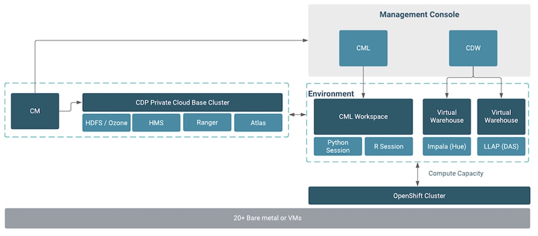
CDP Private Cloud provides a disaggregation of compute and storage and allows independent scaling of compute and storage clusters. Through the use of containerized applications deployed on Kubernetes, CDP Private Cloud brings both agility and predictable performance to analytic applications. CDP Private Cloud gets unified security, governance, and metadata management through Cloudera Shared Data Experience (SDX), which is available on a CDP Private Cloud Base cluster.
CDP Private Cloud users can rapidly provision and deploy Cloudera Data Warehousing and Cloudera Machine Learning services through the Management Console, and easily scale them up or down as required.
A CDP Private Cloud deployment requires you to have a Private Cloud Base cluster and a RedHat OpenShift Kubernetes cluster. The OpenShift cluster is set up on a Bare Metal deployment. The Private Cloud deployment process involves configuring Management Console on the OpenShift cluster, registering an environment by providing details of the Data Lake configured on the Base cluster, and then creating the workloads.
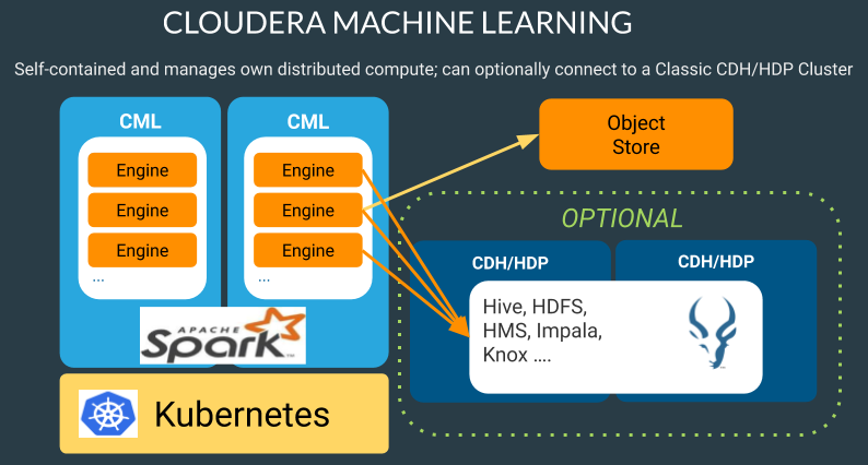
Cloudera Machine Learning
Machine learning has become one of the most critical capabilities for modern businesses to grow and stay competitive today. From automating internal processes to optimizing the design, creation, and marketing processes behind virtually every product consumed, ML models have permeated almost every aspect of our work and personal lives.
Cloudera Machine Learning (CML) is Cloudera’s new cloud-native machine learning service, built for CDP. The CML service provisions clusters, also known as ML workspaces, that run natively on Kubernetes.
Each ML workspace enable teams of data scientists to develop, test, train, and ultimately deploy machine learning models for building predictive applications all on the data under management within the enterprise data cloud. ML workspaces are ephemeral, allowing you to create and delete them on-demand. ML workspaces support fully containerized execution of Python, R, Scala, and Spark workloads through flexible and extensible engines.
Cloudera Machine Learning enables you to:
● Easily onboard a new tenant and provision an ML workspace in a shared OpenShift environment.
● Enable data scientists to access shared data on CDP Private Cloud Base and CDW.
● Leverage Spark-on-K8s to spin up and down Spark clusters on demand.
Apache Ozone is a scalable, redundant, and distributed object store for Hadoop. Apart from scaling to billions of objects of varying sizes, Ozone can function effectively in containerized environments such as Kubernetes and YARN. Applications using frameworks like Apache Spark, YARN and Hive work natively without any modifications. Apache Ozone is built on a highly available, replicated block storage layer called Hadoop Distributed Data Store (HDDS).
Ozone consists of volumes, buckets, and keys:
● Volumes are similar to user accounts. Only administrators can create or delete volumes.
● Buckets are similar to directories. A bucket can contain any number of keys, but buckets cannot contain other buckets.
● Keys are similar to files. Each key is part of a bucket, which, in turn, belongs to a volume. Ozone stores data as keys inside these buckets.
When a key is written to Apache Ozone, the associated data is stored on the DataNodes in chunks called blocks. Therefore, each key is associated with one or more blocks. Within the DataNodes, a series of unrelated blocks is stored in a container, allowing many blocks to be managed as a single entity.
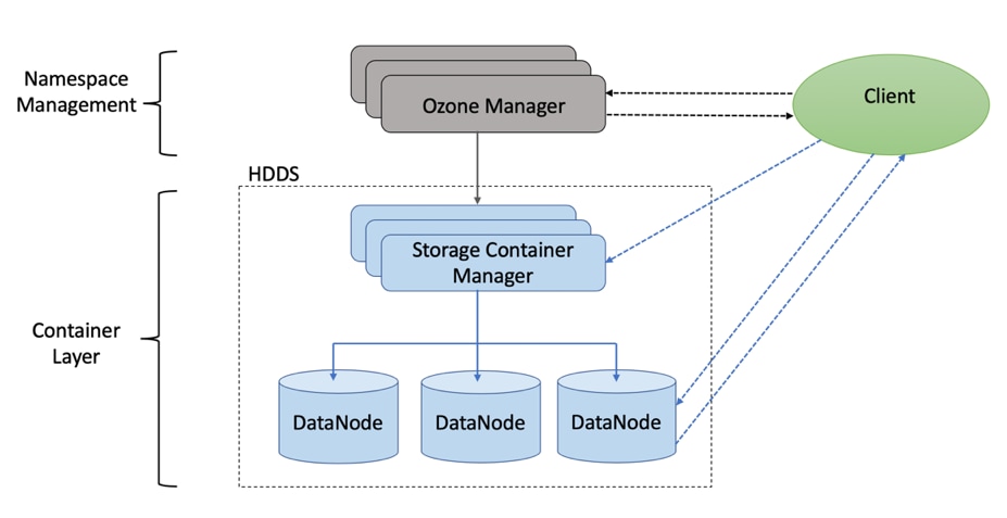
Apache Ozone separates management of namespaces and storage, helping it to scale effectively. Ozone Manager manages the namespaces while Storage Container Manager handles the containers.
Apache Ozone is a distributed key-value store that can manage both small and large files alike. While HDFS provides POSIX-like semantics, Ozone looks and behaves like an Object Store.
Figure 25. Basic Architecture for Ozone
Persistent Storage for Kubernetes
Workloads deployed in containers and orchestrated via Kubernetes(K8) are either stateless or stateful. By default, K8 workloads are stateless. Stateless application don’t persist, which means it uses temporary storage provided within K8 and destroys once the application or pod is terminated. That’s why we call containers are ephemeral in nature, data associated with containers can be lost once the container is terminated or accidentally crashed. Furthermore, data can’t be shared among other containers either.
For stateful application, persistent storage is the first “must have” requirement. Kubernetes supports various persistent storage solutions that help addressing this problem and support stateful workloads in a containerized environment. Kubernetes introduces the concept of Persistent Volumes, which exist independently of containers, survive even after containers shut down, and can be requested and consumed by containerized workloads.
There are various methods of providing persistent storage to containers. However, in this reference design, Portworx is used to provide persistent volume for Cloudera Private Cloud control plane and Cloudera Machine Learning backed by Red Hat OpenShift Container Platform.
Portworx Enterprise
Portworx Enterprise is the cloud native storage and data management platform that enterprises trust to manage data in containers and provides the following:
● Run any service offered on Cisco UCS in production with Portworx’s high-performance storage, high availability, disaster recovery, backup, and security solutions.
● Run any database or data-rich application on Kubernetes, even those that require strict performance, backup and disaster recovery, security, and data mobility.
● Improve application performance and uptime by avoiding the limitations of storage platforms built for VMs, not containers.
● Achieve Zero Recovery Point Objective (RPO) and < 1 minute Recovery Time Objective (RTO) Disaster Recovery for mission-critical data services.
● Seamlessly backup and migrate entire AI applications between clouds and on prem data centers.
● Reduce storage costs using Portworx Operator for Capacity Management.
Portworx solves the five most common problems DevOps teams encounter when running database containers and other stateful services in production:
● High availability: For all of your databases and stateful containers.
● Backup and recovery: Seamlessly backup any application running on Kubernetes to any S3-compatible object storage with the click of a button. Recover to any environment just as easily.
● Disaster recovery: No matter how essential your application is, run it with confidence on Kubernetes with Portworx. Achieve Zero RPO Disaster Recovery for data centers in a metropolitan area as well as continuous backups across the WAN for an even greater level of protection.
● Application migrations: Easily move entire applications, including their data, between clusters, clouds, and on-prem data centers.
● Data security: Highly secure, key-managed encryption and data access controls.
Infrastructure and Software Requirements
As illustrated in Figure 27, this CVD was designed with the following:
· 3 x C240 M5 RedHat OpenShift Container Platform Master nodes
· 16 x C240 M5 RedHat OpenShift Container Platform worker nodes
· Cloudera Data Platform Private Cloud Experiences running on the RedHat OpenShift Container Platform
· 1 x C240 M5 bootstrap node for RedHat OpenShift Container Platform (not shown in the figure)
· 1 x C240 running HA Proxy (not shown in the figure)
· Cloudera Data Platform Private Cloud Base (the data lake) which is not detailed in this CVD but is extensively explained in the CVDs published here: http://www.cisco.com/go/bigdata_design.
Single-rack consists of two vertical PDUs and two Cisco UCS Fabric Interconnect with 16 Cisco UCS C220 M5 Rack Servers connected to each of the vertical PDUs for redundancy. This ensure availability during power source failure. Figure 26 illustrates a 40 Gigabit Ethernet link from each server is connected to both Fabric Interconnects.
![]() Cisco UCS VIC ports connected to each Cisco Nexus switch in active-standby configuration with active links configured on switch A with pinning recovery to switch A in case of link failure in RHEL OS bond configuration to keep traffic locally on leaf switch.
Cisco UCS VIC ports connected to each Cisco Nexus switch in active-standby configuration with active links configured on switch A with pinning recovery to switch A in case of link failure in RHEL OS bond configuration to keep traffic locally on leaf switch.
![]() Virtual port-channel to Northbound/Spine switch consumes only cross domain traffic meaning server to server communication which are connected to two separate pair of leaf switch.
Virtual port-channel to Northbound/Spine switch consumes only cross domain traffic meaning server to server communication which are connected to two separate pair of leaf switch.
![]() The same architecture can be implemented with Active/Active LACP (mode 4) or balanced-alb (mode 6) based configuration. A pair of Cisco Nexus switch (A/B) are configured with vPC domain and vPC peer-link with LACP configuration as per the Cisco Nexus switch configuration best practice.
The same architecture can be implemented with Active/Active LACP (mode 4) or balanced-alb (mode 6) based configuration. A pair of Cisco Nexus switch (A/B) are configured with vPC domain and vPC peer-link with LACP configuration as per the Cisco Nexus switch configuration best practice.
Figure 26. Cisco Data Intelligence Platform with CDP
![]() Please contact your Cisco representative for country-specific information.
Please contact your Cisco representative for country-specific information.
Port Configuration on Cisco UCS Fabric Interconnect 6332
Table 4 lists the port configuration on Cisco UCS Fabric Interconnect 6332.
Table 4. Port Configuration on Cisco UCS Fabric Interconnect 6332
| Port Type |
Port Number |
| Server |
1-24 |
| Network |
25-32 |
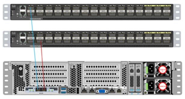
Server Configuration and Cabling for Cisco UCS C240 M5
The Cisco UCS C240 M5 Rack Server is equipped with 2 x Intel Xeon Scalable Family Processor 6230 (2 x 20 cores, 2.1 GHz), 384 GB of memory (12 x 32GB @ 2933MHz), Cisco UCS Virtual Interface Card 1387, Cisco 12-Gbps SAS Modular Raid Controller with 4-GB FBWC, 26 x 2.4 TB 10K rpm SFF SAS HDDs or 12 x 1.6 TB Enterprise Value SATA SSDs, M.2 with 2 x 240-GB SSDs for Boot.
Figure 27 illustrates the port connectivity between the Cisco UCS FI 6332 and Cisco UCS C240 M5 Rack Server. 28 Cisco UCS C240 M5 servers are installed in this configuration.
For information on physical connectivity and single-wire management, go to: https://www.cisco.com/c/en/us/td/docs/unified_computing/ucs/c-series_integration/ucsm4-0/b_C-Series-Integration_UCSM4-0/b_C-Series-Integration_UCSM4-0_chapter_01.html
Figure 27. Fabric Topology for Cisco UCS C240 M5 Rack Server
![]() With Cisco UCS VIC 1455 and 1457, by default a port-channel is turned on between port 1-2 and port-channel between port 3-4. Up to 14 additional vHBAs or vNICs can be created.
With Cisco UCS VIC 1455 and 1457, by default a port-channel is turned on between port 1-2 and port-channel between port 3-4. Up to 14 additional vHBAs or vNICs can be created.
![]() When port-channel mode is set to enabled, the ports on the Cisco Nexus switch should be configured as channel group members.
When port-channel mode is set to enabled, the ports on the Cisco Nexus switch should be configured as channel group members.
![]() The Cisco UCS 1455 and 1457 Virtual Interface Cards, in non-port channel mode, provide four vHBAs and four vNICs by default. Up to 10 additional vHBAs or vNICs can be created.
The Cisco UCS 1455 and 1457 Virtual Interface Cards, in non-port channel mode, provide four vHBAs and four vNICs by default. Up to 10 additional vHBAs or vNICs can be created.
![]() As a best practice, select port 1 and 3 to connect to a pair of Cisco Nexus switch, port 2 and 4 can be added without the need for any additional changes if desired.
As a best practice, select port 1 and 3 to connect to a pair of Cisco Nexus switch, port 2 and 4 can be added without the need for any additional changes if desired.
![]() Switching between port-channel mode on/off requires server reboot.
Switching between port-channel mode on/off requires server reboot.
![]() For detailed configuration using Cisco Intersight, see https://www.intersight.com/help/resources/creating_network_policies
For detailed configuration using Cisco Intersight, see https://www.intersight.com/help/resources/creating_network_policies
Software Distributions and Firmware Versions
The software distributions required versions are listed in Table 5.
Table 5. Software Distribution and Version
| Layer |
Component |
Version or Release |
| Compute |
Cisco UCS C240 M5 |
4.1(2b) |
| Network |
Cisco UCS Fabric Interconnect |
4.1(2b) |
| Cisco UCS VIC1497 Firmware |
5.1(2e) |
|
| Storage |
Cisco 12G Modular RAID Controller |
51.10.0-3612 |
| Storage Controller SAS |
29.00.1-0356 |
|
| LSI MegaRAID SAS Driver |
07.708.03.00 |
|
| SAS Expander |
07.710.50.00-rh1 |
|
| Software |
Red Hat Enterprise Linux Server |
7.8 |
| Red Hat CoreOS |
4.5 |
|
| Red Hat OpenShift Container Platform |
4.5 |
|
| Cloudera CDP Private Cloud Base |
7.1.4 |
|
| Cloudera Data Platform Private Cloud Experiences |
1.1 |
|
| Hadoop |
3.1.1 |
|
| Spark |
2.4.5 |
|
|
|
Portworx |
2.6 |
![]() The latest drivers can be downloaded from here: https://software.cisco.com/download/home/283862063/type/283853158/release/4.1(2c)
The latest drivers can be downloaded from here: https://software.cisco.com/download/home/283862063/type/283853158/release/4.1(2c)
There are many platform dependencies to enable Cloudera Data Platform Private Cloud Experiences running on RedHat OpenShift Container Platform. The containers need to access data stored on HDFS in Cloudera Data Platform Private Cloud Base in a fully secure manner.
The following are the prerequisites needed to enable this solution:
● Network requirements
● Security requirements
● Operating System requirements
● RedHat OpenShift Container Platform requirements
● Cloudera Private Cloud persistence storage requirements
● NFS requirements
● Cloudera requirements
Network Bandwidth Between HDFS/Ozone and Private Cloud
Cloudera Base cluster that houses HDFS storage and Cloudera Private Cloud compute-only clusters should be reachable with no more than a 4:1 oversubscription in order to be able to read from and write to the base HDFS cluster. The recommended network architecture is Spine-Leaf between the spine and leaf switches. Additional routing hops should be avoided in production and ideally both HDFS/Ozone storage and Cloudera Private Cloud are on the same network.
For more information, see: https://docs.cloudera.com/cdp-private-cloud-base/7.1.4/cdppvc-installation/topics/cdppvc-installation-networking.html
Both Cloudera Base and Cloudera Private Cloud cluster should have their time synched with the NTP Clock time from same the NTP source. Also make sure, Active Directory server where Kerberos is setup for data lake and for other services must also be synced with same NTP source.
![]() DNS is required for this solution. It is the requirement for setting up Active Directory, Kerberos, Cloudera Manager authentication, and OpenShift.
DNS is required for this solution. It is the requirement for setting up Active Directory, Kerberos, Cloudera Manager authentication, and OpenShift.
DNS must have the following:
● Each host whether Cloudera Manger or Red Hat OpenShift must be accessible via DNS.
● DNS must be configured for forward AND reverse for each host. Reverse is required for Kerberos authentication to the Base Cloudera cluster.
● Cloudera Manager host must be able to resolve hostname of Red Hat OpenShift ingress/route via DNS of wildcard entry to load balancer of OpenShift Container Platform.
● Service DNS entry must be configured for ETCD cluster. For each control plane machine, OpenShift Container Platform also requires an SRV DNS record for etcd server on that machine with priority 0, weight 10 and port 2380.
● A wildcard DNS entry is required for resolving the ingress/route for applications.
Cloudera Data Platform Requirements
The cluster must be configured with JDK 11, JDK8 is not supported. You can use Oracle, OpenJDK 11.04, or higher. JAVA 11 is a JKS requirement and must be met. In this CVD we used Oracle JDK 11.0.9.
Kerberos must be configured using an Active Directory(AD) or MIT KDC. The Kerberos Key Distribution Center (KDC) will use the domain’s Active Directory service database as its account database. An Active Directory server is recommended for default Kerberos implementations and will be used in the validation of this solution. Kerberos will be enabled for all services in the cluster.
![]() Red Hat IPA/Identity Management is currently not supported.
Red Hat IPA/Identity Management is currently not supported.
Cloudera Manager/Runtime database must be Postgresql 10. Additional databases are on roadmap.
![]() Cloudera Data Warehouse requires Postgresql 10 must be configured with SSL.
Cloudera Data Warehouse requires Postgresql 10 must be configured with SSL.
Configure Cloudera Manager with TLS
The cluster must be configured with TLS. AutoTLS is recommended which uses an internal certificate authority (CA) created and managed by Cloudera Manager. Auto-TLS automates the creation of an internal certificate authority (CA) and deployment of certificates across all cluster hosts.
Manual TLS add additional requirements and must be met according to the guidelines mentioned here: https://docs.cloudera.com/cdp-private-cloud-base/7.1.4/security-encrypting-data-in-transit/topics/cm-security-tls-comparing.html
TLS uses JKS-format (Java KeyStore)
Cloudera Manager Server, Cloudera Management Service, and many other CDP services use JKS formatted keystores and certificates. Java 11 is required for JKS.
The cluster must be setup with a license with entitlements for installing Cloudera Private Cloud. 60 days evaluation license for Cloudera Data Platform Private Cloud Base does not allow you to set up CDP Private Cloud Experiences.
The following minimum services must be configured and setup in Data Lake for private cloud registration process:
● HDFS, Hive Metastore, Ranger, and Atlas.
● There are other dependent services such as Solr for Ranger and HBase and Kafka for Atlas that must be configured.
● All services within the cluster must be in good health. Otherwise, environment registration for private cloud will fail.
Cloudera Data Platform Private Cloud Experiences Requirements
Cloudera Data Platform Private Cloud Experiences works on top of Cloudera Data Platform Private Cloud Base 7.1.3 and above, which together comprise the on-premises version of CDP. If Cloudera Data Warehouse (CDW) is deployed, since it requires ACID capabilities of HIVE, the recommended option is Cloudera Data Platform Private Cloud Base 7.1.4 and above.
Custom service account names are not allowed. Must use default service names for example, hdfs, hive, and so on.
Operating Systems Requirements
Current Support
Currently only RHEL 7.6, 7.7, 7.8 and 7.9 is supported.
![]() For more details about supported versions, go to: https://docs.cloudera.com/cdp-private-cloud-base/7.1.4/installation/topics/cdpdc-requirements-supported-versions.html
For more details about supported versions, go to: https://docs.cloudera.com/cdp-private-cloud-base/7.1.4/installation/topics/cdpdc-requirements-supported-versions.html
Dedicated Red Hat OpenShift Cluster
Currently Cloudera Private Cloud requires a Red Hat OpenShift Container Platform fully dedicated only to Cloudera Private Cloud. In the future it is expected to be supported on shared RedHat OpenShift Container Platform.
![]() For CDP Private Cloud, Red Hat OpenShift Container Platform should only contain worker nodes with CoreOS. RHOCP however supports to have worker nodes running on RHEL, but it is not supported for CDP Private cloud at this point.
For CDP Private Cloud, Red Hat OpenShift Container Platform should only contain worker nodes with CoreOS. RHOCP however supports to have worker nodes running on RHEL, but it is not supported for CDP Private cloud at this point.
RedHat OpenShift Container Platform Requirements
There are two approaches for OCP deployment:
● Installer Provisioned Infrastructure (IPI)
● User Provisioned Infrastructure (UPI)
To learn more about these installation types, please refer to the Red Hat documentation here: https://docs.openshift.com/container-platform/4.5/installing/installing_bare_metal/installing-bare-metal.html#installation-infrastructure-user-infra_installing-bare-metal
This solution uses UPI to deploy RedHat OpenShift Container Platform.
If air gapped from the internet, the K8s cluster needs an Image repository that is reachable. Registries solutions known to work include docker-distribution and Artifactory. Registries not known to work are Quay and RH internal image reg.
Load Balancer (HA-Proxy) must allow non-terminating HTTPS and in one case "websockets" via port 80 (required for CML).
HA proxy is must and must have good network connectivity. It load balances all master (control traffic), etcd traffic and wild card * app traffic. Port 80 and 443 should not be occupied by any http service running on this node.
![]() For this CVD, we used HAproxy load balancer and set it up in RHEL. It is recommended to use external load balancer for production grade setup. Load balancer exists in some form or the other in almost all enterprise networks. If planning to use HAproxy as a load balancer, implement high availability with keep-alive VIP.
For this CVD, we used HAproxy load balancer and set it up in RHEL. It is recommended to use external load balancer for production grade setup. Load balancer exists in some form or the other in almost all enterprise networks. If planning to use HAproxy as a load balancer, implement high availability with keep-alive VIP.
DHCP is optional, however, DHCP is recommended for large scale deployment to manage the machines for the cluster long-term. In this reference architecture, DHCP is not used. It is based on setting up static IP addresses for RHOCP nodes.
![]() If DHCP is used, make sure DHCP server is configured to provide persistent IP addresses and host names to the cluster machines.
If DHCP is used, make sure DHCP server is configured to provide persistent IP addresses and host names to the cluster machines.
Host OS Firewall for Required Ports
Host and HAproxy firewall must be configured for all required ports are outlined in Red Hat OpenShift 4.5 documentation found here: https://docs.openshift.com/container-platform/4.5/installing/installing_bare_metal/installing-bare-metal.html#installation-network-user-infra_installing-bare-metal
Local Registry
When using a local registry, images must be loaded from tarballs using copy script found here: https://docs.cloudera.com/cdp-private-cloud-base/7.1.4/cdppvc-installation/topics/cdppvc-installation-steps.html
Cloudera Private Cloud Storage Requirements
Persistent Volume Storage is a requirement and should be configured in Red Hat OpenShift. Cloudera Private Cloud has specific storage requirement for each of the following components:
● Private Cloud control plane
● Cloudera Machine Learning (CML)
● Cloudera Data Warehouse (CDW)
Consistent Linux Storage Device Naming and Order
Linux storage device naming should be consistent across reboot. This is the requirement for utilizing linux disk devices to be configured for persistent storage. Cisco UCS offers configuring storage profile and this can be easily achieved through storage profiles configuration. Use of storage profile to create disk group for each disk (slot number) and add those group in the profile. Verify LUN-ID in server storage tab of server profile for verification.
Hardware RAID 1 will be configured for boot disk in all OpenShift nodes. OpenShift nodes will be deploying Red Hat CoreOS, single boot device name will be present during the install and this device will be configured with two M.2 SSDs RAID-1 in server’s profile.
Block Storage is provisioned in the form of Persistent Volumes (PV's). Rook Ceph, Portworx and OCS know to work.
![]() This CVD uses Portworx for persistence volume. The "Default Class" attribute must be set to "true" on Block Storage provider's Storage Class for Private Cloud deployment.
This CVD uses Portworx for persistence volume. The "Default Class" attribute must be set to "true" on Block Storage provider's Storage Class for Private Cloud deployment.
Control Plane, CML, and CDW Storage, Memory, and Cores
The exact amount of storage classified as block or filesystem storage will depend on the specific workloads (Machine Learning or Data Warehouse) and how they are used:
● Data Warehousing will require minimum of 16 cores, 128 GB of memory, and 600 GB of locally attached storage, with 100 GB of persistent volume storage on filesystem mounts, per executor. 32+ cores (enabled with Hyper-Threading) and 384GB of RAM is recommended.
● Machine learning requirements on CPU, memory, and storage largely depend on the nature of your machine learning jobs; 4TB of persistent volume block storage is required per Machine Learning Workspace instance for storing different kinds of metadata related to workspace configuration. Additionally, Machine Learning requires access to NFS storage routable from all pods running in the OpenShift cluster.
● Monitoring uses a large Prometheus instance to scrape workloads. Disk usage depends on the scale of the workloads. Cloudera recommends 60 GB.
Table 6. CML and CDW Storage Requirements
| Local Storage (for example ext4) |
Block PV (Portworx) |
NFS |
|
| Control Plane |
N/A |
250 GB |
N/A |
| CDW |
600 GB per virtual warehouse executor by using OpenShift Local Storage Operator (SSD/NVMe Recommended) |
100 GB per virtual warehouse |
N/A |
| CML |
N/A |
4 TB per workspace |
1 TB per workspace (depending on ML user files) |
![]() When you add memory and storage, it is very important that you add it in the increments stated:
When you add memory and storage, it is very important that you add it in the increments stated:
- increments of 128 GB of memory
- increments of 600 GB of locally attached SSD/NVMe storage
- increments of 100 GB (in 5 chunks of 20 GB each) of persistent volume storage
![]() Kubernetes only utilizes the memory and storage in the above increments. If you add memory or storage that is not in the above increments, the memory and storage that exceeds these increments is not used for executor pods. Instead, the extra memory and storage can be used by other pods that require fewer resources.
Kubernetes only utilizes the memory and storage in the above increments. If you add memory or storage that is not in the above increments, the memory and storage that exceeds these increments is not used for executor pods. Instead, the extra memory and storage can be used by other pods that require fewer resources.
For example, if you add 200 GB of memory, only 128 GB is used by the executor pods. If you add 2 TB of locally attached storage, only 1.8 TB is used by the executor pods.
NFS Requirement
Cloudera Machine Learning (CML) requires NFS for storing project files and folders. An internal user-space NFS server can be deployed into the cluster which serves a block storage device (persistent volume) managed by the cluster’s software defined storage (SDS) system, such as Ceph, Portworx, and so on. This is the recommended option for CML in Private Cloud.
![]() The NFS storage should be used only for storing project files and folders, and not for any other CML data, such as PostgreSQL database, and livelog.
The NFS storage should be used only for storing project files and folders, and not for any other CML data, such as PostgreSQL database, and livelog.
![]() The CML does not support shared volumes, such as Portworx shared volumes, for storing project files
The CML does not support shared volumes, such as Portworx shared volumes, for storing project files
Persistent Storage using Local Volumes
Cloudera's Data Warehouse Experience (CDW) requires local storage for purposes of query cache, in addition to Block persistent volumes. OpenShift Container Platform can be provisioned with persistent storage by using local volumes. Local persistent volumes allow you to access local storage devices, such as a disk or partition, by using the standard PVC interface. In production, this should be SSD/NVMe device local to each worker. Non-prod could use spinning media.
Deployment Hardware and Software
This section details the Cisco UCS C240 M5 Rack Servers configuration with Cisco UCS Manager accessed via Cisco Intersight that was done as part of the infrastructure build out. The racking, power, and installation of the Cisco UCS Rack Server is described in the physical topology section earlier in this document. For detailed installation information, refer to the Cisco Integrated Management Controller Configuration Guide.
This document assumes you are using Cisco Data Intelligence Platform with Cloudera Data Platform Private Cloud Base as outlined in the previously published Cisco Validated Design. For detailed deployment information, refer to the Design Zone for Big Data and Analytics which describes the steps to deploy Cisco UCS Fabric Interconnect/Cisco UCS Manager Managed UCS servers with CDP PvC Base.
The prerequisites for Cloudera Private Cloud deployment are as follows:
● Enable TLS on the Cloudera Manager cluster for communication with components and services
● Set up Kerberos on these clusters using an Active Directory or MIT KDC
● Ensure that the CDP Private Cloud Base cluster is on the same network as the OpenShift cluster
● Configure PostgreSQL database as an external database for the CDP Private Cloud Base cluster components
● Configure the CDP Private Cloud Base cluster hostnames to be forward and reverse resolvable in DNS from the OpenShift cluster
● Allow websocket traffic and https traffic when you use a load balancer with the OpenShift external API
Enable AutoTLS
Auto-TLS is managed using the certmanager utility, which is included in the Cloudera Manager Agent software, and not the Cloudera Manager Server software. You must install the Cloudera Manager Agent software on the Cloudera Manager Server host to be able to use the utility. You can use certmanager to manage auto-TLS on a new installation. For more information, go to: Configuring TLS Encryption for Cloudera Manager Using Auto-TLS
To enable AutoTLS, follow these steps:
1. The certmanager syntax is as follows:
/opt/cloudera/cm-agent/bin/certmanager [OPTIONS] COMMAND [ARGS]...
# export JAVA_HOME=/usr/java/jdk-11.0.9; /opt/cloudera/cm-agent/bin/certmanager setup --configure-services
2. The certificates, keystores, and password files generated by auto-TLS are stored in /var/lib/cloudera-scm-agent/agent-cert on each Cloudera Manager Agent.
cd /var/lib/cloudera-scm-agent/agent-cert/
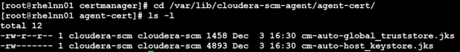
3. Restart Cloudera Manager Server.
# systemctl restart cloudera-scm-server
Enable Kerberos
Cloudera Manager provides a wizard for integrating your organization’s Kerberos with your cluster to provide authentication services. Cloudera Manager clusters can be integrated with MIT Kerberos, Red Hat Identity Management (or the upstream FreeIPA), or Microsoft Active Directory. For more information, Enable Kerberos Authentication for CDP
![]() In our lab, we configured Active-Directory based Kerberos authentication. We presume that Active Directory is pre-configured with OU, user(s) and proper authentication is setup for Kerberos Authentication. LDAP users and bind users are expected to be in the same branch/OU.
In our lab, we configured Active-Directory based Kerberos authentication. We presume that Active Directory is pre-configured with OU, user(s) and proper authentication is setup for Kerberos Authentication. LDAP users and bind users are expected to be in the same branch/OU.
![]() Before integrating Kerberos with your cluster, configure TLS encryption between Cloudera Manager Server and all Cloudera Manager Agent host systems in the cluster. During the Kerberos integration process, Cloudera Manager Server sends keytab files to the Cloudera Manager Agent hosts, and TLS encrypts the network communication, so these files are protected.
Before integrating Kerberos with your cluster, configure TLS encryption between Cloudera Manager Server and all Cloudera Manager Agent host systems in the cluster. During the Kerberos integration process, Cloudera Manager Server sends keytab files to the Cloudera Manager Agent hosts, and TLS encrypts the network communication, so these files are protected.
![]() For Active Directory setup, you must have access to AD instance for initial setup or for on-going management, or you will need help from your AD administrator.
For Active Directory setup, you must have access to AD instance for initial setup or for on-going management, or you will need help from your AD administrator.
You can verify by running the following command that Kerberos is properly setup within your AD environment prior to setup KDC in Cloudera Manager or for troubleshooting purposes.
[root@rhel1 ~]# kinit cdpbind
Password for cdpbind@HDP3.CISCO.LOCAL:
[root@rhel1 ~]#
[root@rhel1 ~]#
[root@rhel1 ~]# klist
Ticket cache: FILE:/tmp/krb5cc_0
Default principal: cdpbind@HDP3.CISCO.LOCAL
Valid starting Expires Service principal
02/22/2021 16:12:59 02/23/2021 02:12:59 krbtgt/HDP3.CISCO.LOCAL @HDP3.CISCO.LOCAL
renew until 03/01/2021 16:12:48
To enable Kerberos, follow these steps:
1. In Cloudera manager console select setup a KDC.
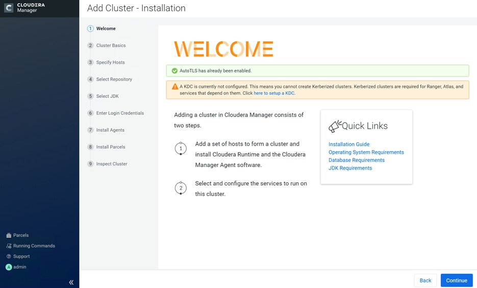
2. Select Active Directory as KDC Type.
3. Install OpenLDAP client libraries on all Cloudera Manager server hosts:
# ansible all -m command -a "yum install -y openldap-clients krb5-workstation krb5-libs"
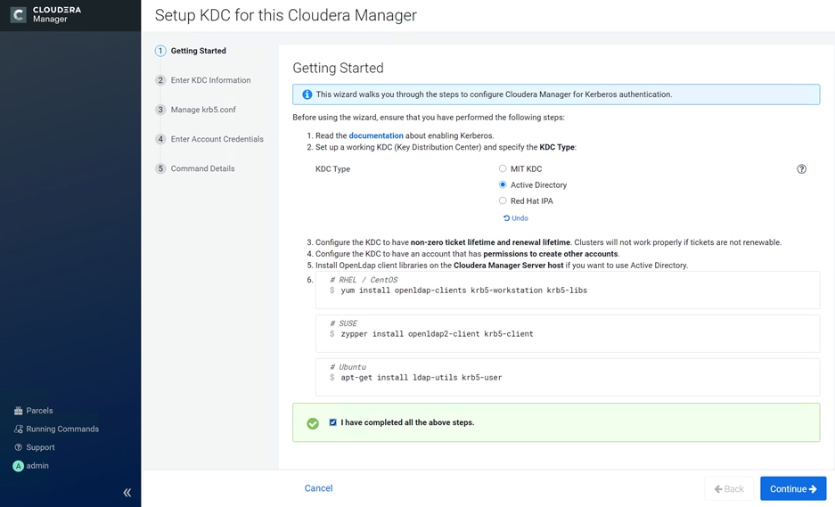
4. Check the box for Manage krb5.conf through Cloudera Manager. This will install krb5.conf file in all the hosts selected for data lake.
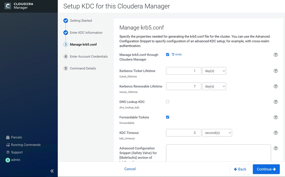
5. Enter account credentials for the bind user which you have created in AD. This credential will be used to create service accounts in AD. In our lab setup, cdpbind user is created in AD.
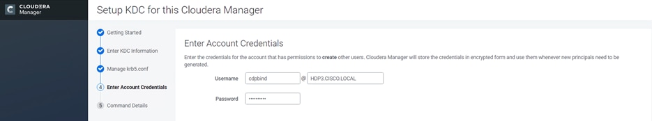
6. Click Finish to complete the KDC setup.
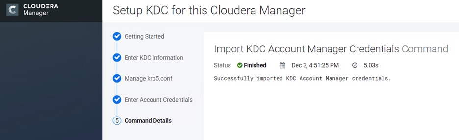
7. Verify krb5.conf file by running the command as shown below. Sample krb5.conf created as part of the Kerberos configuration enablement.
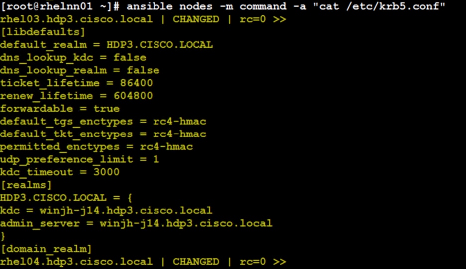
Enabling Kerberos as part of the cluster configuration is shown below:
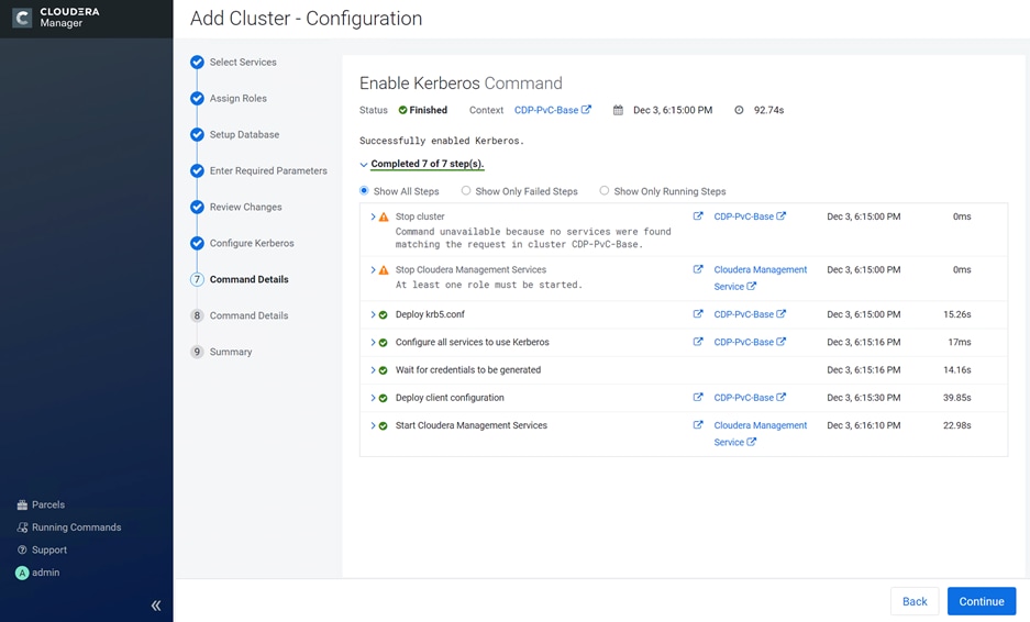
After successfully enabling Auto TLS and Kerberos Cloudera Manager Welcome wizard changes to reflect the configuration changes.
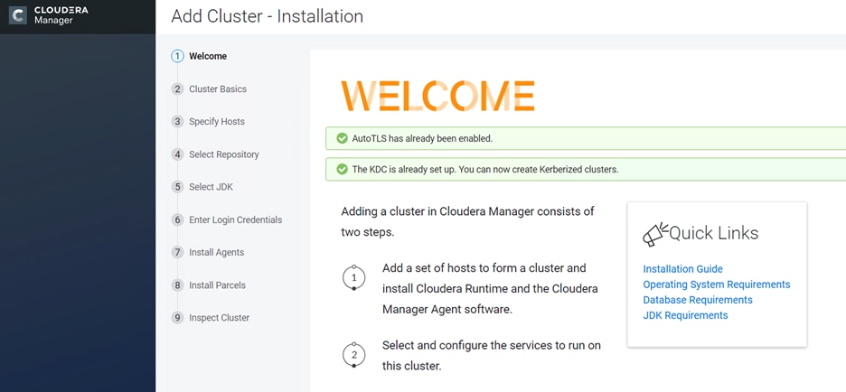
Red Hat OpenShift Container Platform (RHOCP)
Review the prerequisites outlined for RHOCP deployment on bare metal here: https://docs.openshift.com/container-platform/4.5/installing/installing_bare_metal/installing-bare-metal.html#prerequisites
Figure 28 shows the logical view of the RHOCP deployment.
Figure 28. Logical topology of the RHOCP
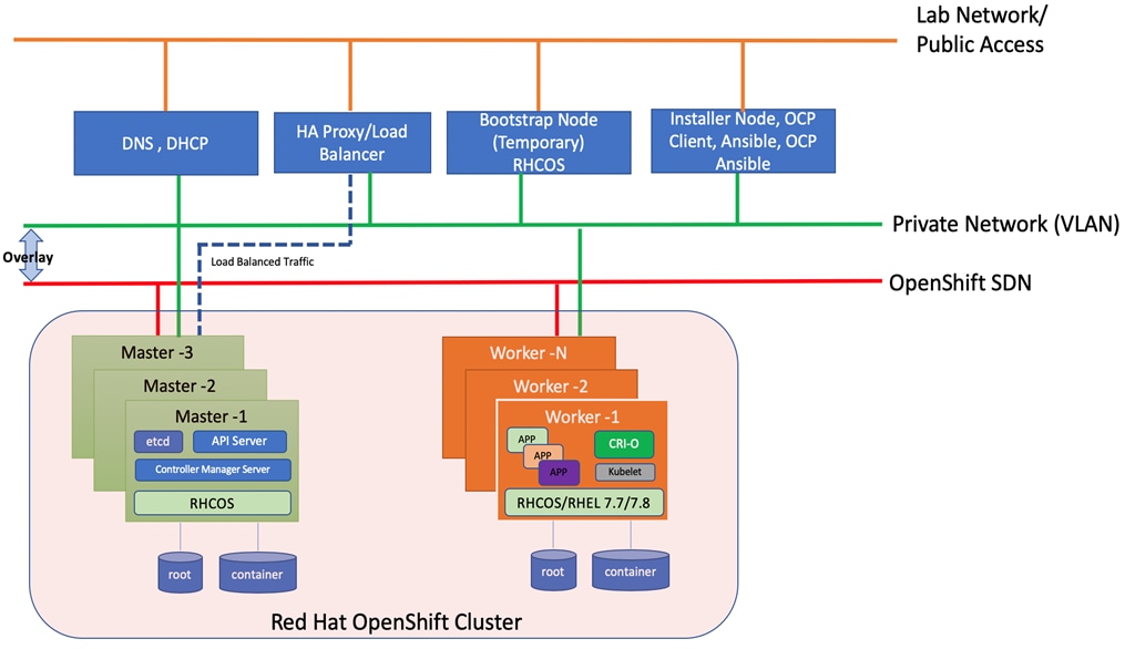
Table 7. Software versions
| Software |
Version |
| Red Hat OpenShift |
4.5.6 |
| Red Hat CoreOS |
4.5.6 |
| Red Hat Enterprise Linux |
7.8 |
| Ansible |
2.9.14 |
| OpenShift Installation Program on Linux |
4.5.6 |
| OpenShift CLI on Linux |
4.5.6 |
| Portworx |
2.6 |
Prerequisites
The following are the prerequisites for Red Hat OpenShift Container Platform:
● Configure DHCP or set static IP addresses on each node.
● Provision the required load balancers.
● DNS is absolute MUST. Without proper DNS configuration, installation will not continue.
● Ensure network connectivity among nodes, DNS, DHCP (if used), HAProxy, Installer or Bastion node.
![]() It is recommended to use the DHCP server to manage the machines for the cluster long-term. Ensure that the DHCP server is configured to provide persistent IP addresses and host names to the cluster machines.
It is recommended to use the DHCP server to manage the machines for the cluster long-term. Ensure that the DHCP server is configured to provide persistent IP addresses and host names to the cluster machines.
Minimum Required Machines
The smallest OpenShift Container Platform clusters require the following hosts:
● 1 x temporary bootstrap machine
● 3 x Control plane, or master machines
● 2+ compute machines, which are also known as worker machines
![]() Bootstrap node is only used during the install time. its main purpose is to run bootkube. bootkube technically provides a temporary single node master k8 for bootstraping. After installation, this node can be removed or repurposed.
Bootstrap node is only used during the install time. its main purpose is to run bootkube. bootkube technically provides a temporary single node master k8 for bootstraping. After installation, this node can be removed or repurposed.
![]() For control plane high availability, it is recommended to use separate physical machine.
For control plane high availability, it is recommended to use separate physical machine.
High-level Red Hat OpenShift Installation Checklist
There are two approaches for OCP deployment:
● Installer Provisioned Infrastructure (IPI)
● User Provisioned Infrastructure (UPI)
For detailed information about the installation types, please refer to Red Hat documentation. This OCP deployment is based on UPI.
UPI based install involved the following high-level steps:
1. Configure DNS.
2. Configure Load Balancer.
3. Setup non-cluster host to run a web server reachable by all nodes.
4. Setup OCP installer program.
5. Setup DHCP (Optional if using static IP).
6. Create install-config.yaml as per your environment.
7. Use the openshift-install command to generate the RHEL CoreOS ignition manifests, host these files via the web server.
8. PXE or ISO boot the cluster members to start the RHEL CoreOS and OpenShift install.
9. Monitor install progress with the openshift-install command.
10. Validate install using OpenShift client tool or launch the web console.
DNS Setup for RHOCP
DNS is used for name resolution and reverse name resolution. DNS A/AAAA or CNAME records are used for name resolution and PTR records are used for reverse name resolution. The reverse records are important because Red Hat Enterprise Linux CoreOS (RHCOS) uses the reverse records to set the host name for all the nodes. Additionally, the reverse records are used to generate the certificate signing requests (CSR) that OpenShift Container Platform needs to operate.
The following DNS records are required for an OpenShift Container Platform cluster that uses user-provisioned infrastructure. A complete DNS record takes the form: <component>.<cluster_name>.<base_domain>.
Table 8. Required DNS records
| Component |
DNS A/AAA Record |
IP Address |
Description |
| Kubernetes API |
api.ocp4.hdp3.cisco.local |
10.13.1.40 |
IP address for the Load balancer for the control plane machines. These records must be resolvable by both clients external to the cluster and from all the nodes within the cluster. The API server must be able to resolve the worker nodes by the host names that are recorded in Kubernetes. If the API server cannot resolve the node names, then proxied API calls can fail, and you cannot retrieve logs from pods. |
| api-int.ocp4.hdp3.cisco.local |
10.13.1.40 |
||
| Bootstrap |
bootstrap.ocp4.hdp3.cisco.local |
10.13.1.44 |
bootstrap machine. |
| Master hosts |
master0.ocp4.hdp3.cisco.local |
10.13.1.41 |
Master nodes |
| master1.ocp4.hdp3.cisco.local |
10.13.1.42 |
||
| master2.ocp4.hdp3.cisco.local |
10.13.1.44 |
||
| Worker hosts |
woker0.ocp4.hdp3.cisco.local |
10.13.1.51 |
Worker nodes |
| woker1.ocp4.hdp3.cisco.local |
10.13.1.52 |
||
| …… |
………. |
||
| woker14.ocp4.hdp3.cisco.local |
10.13.1.65 |
||
| woker15.ocp4.hdp3.cisco.local |
10.13.1.66 |
||
| Etcd-<index> |
etcd-0.ocp4.hdp3.cisco.local |
10.13.1.41 |
Each etcd instance to point to the control plane machines that host the instances. Etcd will be running in respective master nodes |
| etcd-1.ocp4.hdp3.cisco.local |
10.13.1.42 |
||
| etcd-2.ocp4.hdp3.cisco.local |
10.13.1.43 |
||
| _etcd-server-ssl |
_etcd-server-ssl. _tcp.ocp4.hdp3.cisco.local |
etcd-0.ocp4.hdp3.cisco.local |
For each control plane machine, OpenShift Container Platform also requires an SRV DNS record for etcd server on that machine with priority 0, weight 10 and port 2380. A cluster that uses three control plane machines re-quires the following records: |
| _etcd-server-ssl. _tcp.ocp4.hdp3.cisco.local |
etcd-1.ocp4.hdp3.cisco.local |
||
| _etcd-server-ssl. _tcp.ocp4.hdp3.cisco.local |
etcd-2.ocp4.hdp3.cisco.local |
||
| Routes |
*.apps.ocp4.hdp3.cisco.local |
10.13.1.40 |
Load balancer that targets the machines that run the Ingress router pods, which are the worker nodes by default. |
Bastion Node – Installation and Configuration
The Red Hat OpenShift Container Platform bastion node should be installed with Red Hat Enterprise Linux version 7.4 or newer. The user can choose their preferred installation method which could be CIMC mounted vMedia DVD install method. This document does not explain Bastion node OS installation steps, as it is time-tested, standard procedure. Bastion node needs standard base RHEL server operating system packages.
![]() Bastion node configuration for OS, network and storage remains same for both Production and Dev/ Test use case architectures.
Bastion node configuration for OS, network and storage remains same for both Production and Dev/ Test use case architectures.
Create an installation folder on bastion node:
[root@bastion ~]# mkdir -p ocp-install
Set Up Load Balancer
Load balancer is required for Kubernetes API server, both internal and external as well as for OpenShift router.
In this deployment, for simplicity, we used HAproxy to be installed and configured in Linux server. However, existing load balancer can also be configured as long as it can reach to all OpenShift nodes. This document does not make any official recommendation for any specific load balancer. We installed HAproxy single instance in bastion server by running the following command. As previously documented, this HAproxy server install is for reference purpose only, not for production setup.
To set up the load balancer, follow these steps:
1. Install haproxy
[root@bastion ~]# yum install -y haproxy
2. After the install, configure /etc/haproxy/haproxy.cfg file. You need to configure port 6443 and 22623 to point to bootstrap and master nodes. You also need to configure port 80 and 443 to point to the worker nodes. Below is the example of HAproxy config used in this reference design.
![]() Make sure port 80 or 443 is not occupied in the server where HAProxy is being setup
Make sure port 80 or 443 is not occupied in the server where HAProxy is being setup
3. Edit haproxy.cfg file.
[root@bastion ~]# cat /etc/haproxy/haproxy.cfg
#---------------------------------------------------------------------
# Example configuration for a possible web application. See the
# full configuration options online.
#
# http://haproxy.1wt.eu/download/1.4/doc/configuration.txt
#
#---------------------------------------------------------------------
#---------------------------------------------------------------------
# Global settings
#---------------------------------------------------------------------
global
# to have these messages end up in /var/log/haproxy.log you will
# need to:
#
# 1) configure syslog to accept network log events. This is done
# by adding the '-r' option to the SYSLOGD_OPTIONS in
# /etc/sysconfig/syslog
#
# 2) configure local2 events to go to the /var/log/haproxy.log
# file. A line like the following can be added to
# /etc/sysconfig/syslog
#
# local2.* /var/log/haproxy.log
#
log 127.0.0.1 local2
chroot /var/lib/haproxy
pidfile /var/run/haproxy.pid
maxconn 4000
user haproxy
group haproxy
daemon
# turn on stats unix socket
stats socket /var/lib/haproxy/stats
#---------------------------------------------------------------------
# common defaults that all the 'listen' and 'backend' sections will
# use if not designated in their block
#---------------------------------------------------------------------
defaults
mode http
log global
option httplog
option dontlognull
option http-server-close
# option forwardfor except 127.0.0.0/8
option redispatch
retries 3
timeout http-request 10s
timeout queue 1m
timeout connect 10s
timeout client 1m
timeout server 1m
timeout http-keep-alive 10s
timeout check 10s
maxconn 3000
#---------------------------------------------------------------------
# main frontend which proxys to the backends
#---------------------------------------------------------------------
frontend openshift-api-server
bind *:6443
default_backend openshift-api-server
mode tcp
option tcplog
frontend machine-config-server
bind *:22623
default_backend machine-config-server
mode tcp
option tcplog
frontend ingress-http
bind *:80
default_backend ingress-http
mode tcp
option tcplog
frontend ingress-https
bind *:443
default_backend ingress-https
mode tcp
option tcplog
#---------------------------------------------------------------------
# static backend for serving up images, stylesheets and such
#---------------------------------------------------------------------
backend openshift-api-server
balance source
mode tcp
# comment out or delete bootstrap entry after the successful install and restart haproxy
server bootstrap.ocp4.hdp3.cisco.local 10.13.1.44:6443 check
server master0.ocp4.hdp3.cisco.local 10.13.1.41:6443 check
server master1.ocp4.hdp3.cisco.local 10.13.1.42:6443 check
server master2.ocp4.hdp3.cisco.local 10.13.1.43:6443 check
backend machine-config-server
balance source
mode tcp
# comment out or delete bootstrap entry after the successful installation and restart haproxy
server bootstrap.ocp4.hdp3.cisco.local 10.13.1.44:22623 check
server master0.ocp4.hdp3.cisco.local 10.13.1.41:22633 check
server master1.ocp4.hdp3.cisco.local 10.13.1.42:22623 check
server master2.ocp4.hdp3.cisco.local 10.13.1.43:22623 check
backend ingress-http
balance source
mode tcp
server master0.ocp4.hdp3.cisco.local 10.13.1.41:80 check
server master1.ocp4.hdp3.cisco.local 10.13.1.42:80 check
server master2.ocp4.hdp3.cisco.local 10.13.1.43:80 check
server worker0.ocp4.hdp3.cisco.local 10.13.1.51:80 check
server worker1.ocp4.hdp3.cisco.local 10.13.1.52:80 check
server worker2.ocp4.hdp3.cisco.local 10.13.1.53:80 check
server worker3.ocp4.hdp3.cisco.local 10.13.1.54:80 check
server worker4.ocp4.hdp3.cisco.local 10.13.1.55:80 check
server worker5.ocp4.hdp3.cisco.local 10.13.1.56:80 check
server worker6.ocp4.hdp3.cisco.local 10.13.1.57:80 check
server worker7.ocp4.hdp3.cisco.local 10.13.1.58:80 check
server worker8.ocp4.hdp3.cisco.local 10.13.1.59:80 check
server worker9.ocp4.hdp3.cisco.local 10.13.1.60:80 check
server worker10.ocp4.hdp3.cisco.local 10.13.1.61:80 check
server worker11.ocp4.hdp3.cisco.local 10.13.1.62:80 check
server worker12.ocp4.hdp3.cisco.local 10.13.1.63:80 check
server worker13.ocp4.hdp3.cisco.local 10.13.1.64:80 check
server worker14.ocp4.hdp3.cisco.local 10.13.1.65:80 check
server worker15.ocp4.hdp3.cisco.local 10.13.1.66:80 check
backend ingress-https
balance source
mode tcp
server master0.ocp4.hdp3.cisco.local 10.13.1.41:443 check
server master1.ocp4.hdp3.cisco.local 10.13.1.42:443 check
server master2.ocp4.hdp3.cisco.local 10.13.1.43:443 check
server worker0.ocp4.hdp3.cisco.local 10.13.1.51:443 check
server worker1.ocp4.hdp3.cisco.local 10.13.1.52:443 check
server worker2.ocp4.hdp3.cisco.local 10.13.1.53:443 check
server worker3.ocp4.hdp3.cisco.local 10.13.1.54:443 check
server worker4.ocp4.hdp3.cisco.local 10.13.1.55:443 check
server worker5.ocp4.hdp3.cisco.local 10.13.1.56:443 check
server worker6.ocp4.hdp3.cisco.local 10.13.1.57:443 check
server worker7.ocp4.hdp3.cisco.local 10.13.1.58:443 check
server worker8.ocp4.hdp3.cisco.local 10.13.1.59:443 check
server worker9.ocp4.hdp3.cisco.local 10.13.1.60:443 check
server worker10.ocp4.hdp3.cisco.local 10.13.1.61:443 check
server worker11.ocp4.hdp3.cisco.local 10.13.1.62:443 check
server worker12.ocp4.hdp3.cisco.local 10.13.1.63:443 check
server worker13.ocp4.hdp3.cisco.local 10.13.1.64:443 check
server worker14.ocp4.hdp3.cisco.local 10.13.1.65:443 check
server worker15.ocp4.hdp3.cisco.local 10.13.1.66:443 check
4. Restart the HAProxy service and verify that it is running without any issues.
[root@rhel1 ~]# systemctl restart haproxy
[root@rhel1 ~]# systemctl status haproxy -l
![]() Explaining the details of the haproxy.cfg file is beyond the scope of this document. Please refer to the haproxy documentation: https://access.redhat.com/documentation/en-us/red_hat_enterprise_linux/7/html/load_balancer_administration/install_haproxy_example1
Explaining the details of the haproxy.cfg file is beyond the scope of this document. Please refer to the haproxy documentation: https://access.redhat.com/documentation/en-us/red_hat_enterprise_linux/7/html/load_balancer_administration/install_haproxy_example1
![]() Make sure all the ports specified in HAproxy configuration are opened in the server where it is running.
Make sure all the ports specified in HAproxy configuration are opened in the server where it is running.
Figure 29. Reference Design for Load Balancer
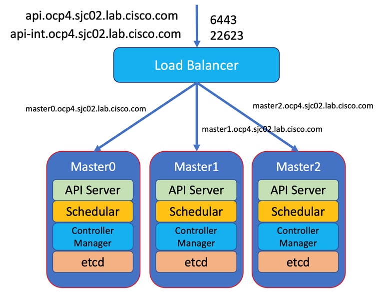
Set Up Webserver
A webserver is also required to be setup for placing ignition configurations and installation images for Red Hat CoreOS. Webserver must be reached by bootstrap, master, and worker nodes during the install. In this design, we setup Apache web server (httpd).
To set up the webserver, follow these steps:
![]() If you are setting up webserver in bastion node for serving installation files, iso, and CoreOS image, make sure it is not using default port 80 as it would conflict with HAproxy configuration
If you are setting up webserver in bastion node for serving installation files, iso, and CoreOS image, make sure it is not using default port 80 as it would conflict with HAproxy configuration
1. If webserver is not already installed. Run the following command in installer server:
[root@bastion ~]# yum install -y httpd
2. Create a folder for ignition files and CoreOS image:
[root@bastion ~]# mkdir -p /var/www/html/ignition-install
3. Download Red Hat CoreOS image to this folder:
[root@bastion ~] cd /var/www/html/ignition-install
[root@rhel1 ignition-install]# curl -J -L -O https://mirror.openshift.com/pub/openshift-v4/x86_64/dependencies/rhcos/4.5/latest/rhcos-4.5.2-x86_64-metal.x86_64.raw.gz

Set Up DHCP (Optional)
DHCP is recommended for large scale production deployment to provide persistent IP addresses and host names to all the cluster nodes. Use IP reservation, so that IP should not change during node reboots.
However, for simplicity we used static IP addresses in this deployment for all the nodes. Acquiring IP addresses from DHCP or boot using the PXE protocol is beyond the scope of this document.
Generate an SSH Private Key and Add to Agent
If you want to perform installation debugging or disaster recovery on your cluster, you must provide an SSH key to both your ssh-agent and the installation program.
You can use this key to SSH into the master, bootstrap, and worker nodes as the user core. When you deploy the cluster, the key is added to the core user’s ~/.ssh/authorized_keys list.
To generate the SSH private key and add it to the agent, follow these steps:
1. Run the following command:
[root@bastion ~]# mkdir ocp-install
[root@bastion ~]# cd ocp-install
[root@bastion ocp-install]# ssh-keygen -t rsa -b 4096 -N '' -f installer
Figure 30. ssh-keygen installer
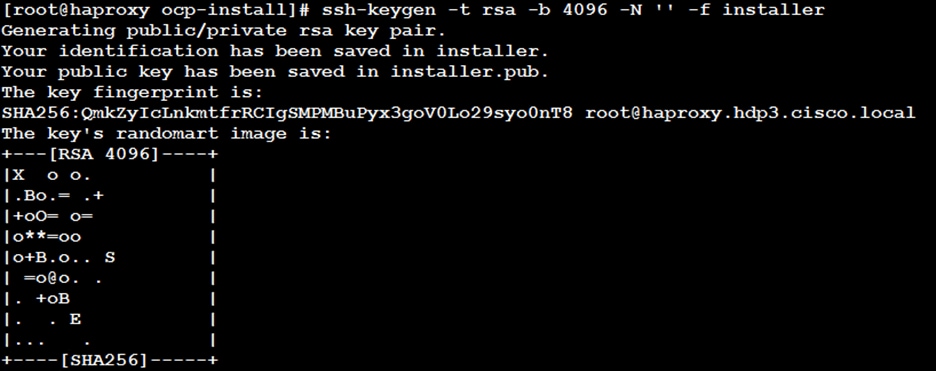
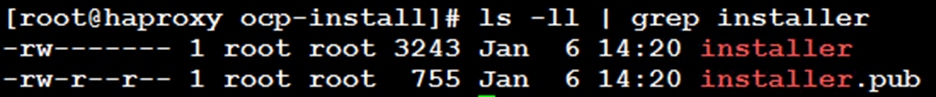
![]() In a production environment, you require disaster recovery and debugging.
In a production environment, you require disaster recovery and debugging.
![]() Specify the path and file name, such as ~/.ssh/id_rsa, of the SSH key. Do not specify an existing SSH key, as it will be overwritten.
Specify the path and file name, such as ~/.ssh/id_rsa, of the SSH key. Do not specify an existing SSH key, as it will be overwritten.
![]() Running this command generates an SSH key that does not require a password in the location that you specified.
Running this command generates an SSH key that does not require a password in the location that you specified.
![]() Specify the path and file name for your SSH private key, such as ~/.ssh/id_rsa
Specify the path and file name for your SSH private key, such as ~/.ssh/id_rsa
![]() When you install OpenShift Container Platform, provide the SSH public key to the installation program. If you install a cluster on infrastructure that you provision, you must provide this key to your cluster’s machines.
When you install OpenShift Container Platform, provide the SSH public key to the installation program. If you install a cluster on infrastructure that you provision, you must provide this key to your cluster’s machines.
2. Start the ssh-agent process as a background task:
[root@bastion ocp-install]# eval "$(ssh-agent -s)"
3. Add your SSH private key to the ssh-agent:
[root@bastion ocp-install]# ssh-add installer
Obtain the Installation Program
Before you install OpenShift Container Platform, download the OpenShift installation file and set it up in a bastion node.
To obtain the installation program, follow these steps:
1. Access the Install OpenShift on Bare Metal with user-provisioned infrastructure page on the Red Hat OpenShift Cluster Manager site.
2. Download the installation program for Linux operating system, and place the file in the ocp-install directory where you will store the installation configuration files.
[root@bastion ocp-install]# curl -J -L -O https://mirror.openshift.com/pub/openshift-v4/clients/ocp/4.5.6/openshift-install-linux-4.5.6.tar.gz
![]() The installation program creates several files on the computer that you use to install your cluster. You must keep both the installation program and the files that the installation program creates after you finish installing the cluster.
The installation program creates several files on the computer that you use to install your cluster. You must keep both the installation program and the files that the installation program creates after you finish installing the cluster.
![]() Deleting the files created by the installation program does not remove your cluster, even if the cluster failed during installation. You must complete the OpenShift Container Platform uninstallation procedures outlined for your specific cloud provider to remove your cluster entirely.
Deleting the files created by the installation program does not remove your cluster, even if the cluster failed during installation. You must complete the OpenShift Container Platform uninstallation procedures outlined for your specific cloud provider to remove your cluster entirely.
3. Extract the installation program. Run the following command:
[root@bastion ocp-install]# tar -zxvf openshift-install-linux-4.5.6.tar.gz
[root@bastion ocp-install]# chmod 777 openshift-install
Download Pull Secret
Installation program requires pull secret. This pull secret allows you to authenticate with the services that are provided by the included authorities, including Quay.io, which serves the container images for OpenShift Container Platform components.
Without pull secret, installation will not continue. It will be specified in install config file in the later section of this document.
To download pull secret, follow these steps:
1. From the OpenShift Cluster Manger site (https://cloud.redhat.com/openshift/install/metal/user-provisioned), pull secret can either be downloaded as .txt file or copied directly in the clipboard.
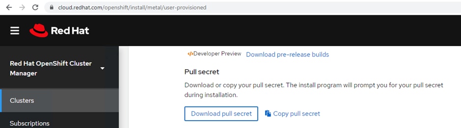
2. Get the pull secret and save it as .txt file.
Install the CLI
Install the OpenShift CLI (oc) in order to interact with OpenShift Container Platform from a command-line interface. You can install (oc) on Linux, Windows, or macOS.
![]() If you installed an earlier version of oc, you cannot use it to complete all of the commands in OpenShift Container Platform 4.5. Download and install the new version of oc.
If you installed an earlier version of oc, you cannot use it to complete all of the commands in OpenShift Container Platform 4.5. Download and install the new version of oc.
Install the CLI on Linux
To install the OpenShift CLI (oc) binary on Linux, follow these steps:
1. Access the Install OpenShift on Bare Metal with user-provisioned infrastructure page on the Red Hat OpenShift Cluster Manager site.
2. Download the CLI program for Linux operating system, and place the file in the ocp-install directory where you will store the installation configuration files:
[root@bastion ocp-install]# curl -J -L -O https://mirror.openshift.com/pub/openshift-v4/clients/ocp/4.5.6/openshift-client-linux-4.5.6.tar.gz
3. Extract the installation program. Run the following command:
[root@bastion ocp-install]# tar -zxvf openshift-client-linux-4.5.6.tar.gz
4. Place the oc binary in a directory that is on your PATH. To check your PATH, execute the following command:
[root@bastion ocp-install]# echo $PATH
/usr/local/sbin:/usr/local/bin:/usr/sbin:/usr/bin:/root/bin:/root/ocp-install/:/root/ocp-install/
[root@bastion ocp-install]# export PATH=$PATH:/root/ocp-install/
5. After you install the CLI, it is available using the oc command:
[root@bastion ocp-install]# oc <command>
Manually Create the Installation Configuration File
For installations of OpenShift Container Platform that use user-provisioned infrastructure, you manually generate your installation configuration file.
![]() Some installation assets, like bootstrap X.509 certificates have short expiration intervals, so you must not reuse an installation directory. If you want to reuse individual files from another cluster installation, you can copy them into your directory. However, the file names for the installation assets might change between releases. Use caution when copying installation files from an earlier OpenShift Container Platform version.
Some installation assets, like bootstrap X.509 certificates have short expiration intervals, so you must not reuse an installation directory. If you want to reuse individual files from another cluster installation, you can copy them into your directory. However, the file names for the installation assets might change between releases. Use caution when copying installation files from an earlier OpenShift Container Platform version.
To manually create the installation configuration file, follow these steps:
1. Customize the install-config.yaml file template and save it in the installation directory. Change the following according to your environment:
a. baseDomain – This is the domain in your environment. For example, we configure hdp3.cisco.local as the base domain.
b. metadata.name – This would be clusterId (Note: This will effectively make all FQDNS ocp4.hdp3.cisco.local)
c. sshKey – generated earlier in the Generate ssh private key section - # cat ~/.ssh/id_rsa.pub
[root@bastion ocp-install]# vi /root/ocp-install/create_install_yaml.sh
cat <<EOF > install-config.yaml
apiVersion: v1
baseDomain: hdp3.cisco.local
compute:
- hyperthreading: Enabled
name: worker
replicas: 0
controlPlane:
hyperthreading: Enabled
name: master
replicas: 3
metadata:
name: ocp4
networking:
clusterNetwork:
- cidr: 10.254.0.0/16
hostPrefix: 24
networkType: OpenShiftSDN
serviceNetwork:
- 172.30.0.0/16
platform:
none: {}
fips: false
pullSecret: '$(< /root/ocp-install/pull-secret.txt)'
sshKey: '$(< /root/ocp-install/installer.pub)'
EOF
[root@bastion ocp-install]# chmod 777 create_install_yaml.sh
[root@bastion ocp-install]# ./ create_install_yaml.sh
![]() You must name this configuration file install-config.yaml.
You must name this configuration file install-config.yaml.
2. Back up the install-config.yaml file so that you can use it to install multiple clusters:
[root@bastion ocp-install]# cp install-config.yaml install-config.yaml.bkp
![]() The install-config.yaml file is consumed during the next step of the installation process. You must back it up now.
The install-config.yaml file is consumed during the next step of the installation process. You must back it up now.
![]() You can customize the install-config.yaml file to specify more details about your OpenShift Container Platform cluster’s platform or modify the values of the required parameters. For more details, https://docs.openshift.com/container-platform/4.5/installing/installing_bare_metal/installing-bare-metal.html#installation-initializing-manual_installing-bare-metal
You can customize the install-config.yaml file to specify more details about your OpenShift Container Platform cluster’s platform or modify the values of the required parameters. For more details, https://docs.openshift.com/container-platform/4.5/installing/installing_bare_metal/installing-bare-metal.html#installation-initializing-manual_installing-bare-metal
Create Kubernetes Manifest and Ignition Configuration Files
Ignition is a tool for manipulating configuration during early boot before the operating system starts. This includes things like writing files (regular files, systemd units, networkd units, and so on) and configuring users. Think of it as a cloud-init that runs once (during first boot).
OpenShift 4 installer generates these ignition configs to prepare the node as an OpenShift either bootstrap, master, or worker node.
To create Kubernetes manifest and Ignition config files, follow these steps:
3. From within your working directory (in this example it's ~/ocp-install) generate the ignition configs:
[root@bastion ocp-install]# ./openshift-install create ignition-configs --dir=~/ocp-install
![]() Make sure install-config.yaml file should be in the working director such as ~/ocp-install directory in this case.
Make sure install-config.yaml file should be in the working director such as ~/ocp-install directory in this case.
![]() Creating ignition config will result in the removal of install-config.yaml file. Make a backup of in-stall-config.yaml before creating ignition configs. You may have to recreate the new one if you need to re-create the ignition config files
Creating ignition config will result in the removal of install-config.yaml file. Make a backup of in-stall-config.yaml before creating ignition configs. You may have to recreate the new one if you need to re-create the ignition config files
The following files are generated in the directory:
.
├── auth
│ ├── kubeadmin-password
│ └── kubeconfig
├── bootstrap.ign
├── master.ign
├── metadata.json
└── worker.ign
As an example, list of installation folders are shown below:
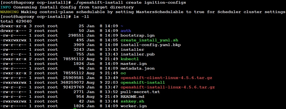
4. Copy the .ign file to your webserver:
[root@bastion ocp-install]# cp *.ign /var/www/html/ignition-install/
5. Provide the appropriate permissions (otherwise, it will not work):
[root@bastion ocp-install]# chmod o+r /var/www/html/ignition-install/*.ign
Download Red Hat Core OS (RHCOS) ISO
Download the RHCOS 4.5.6 iso from the following link:
Install Red Hat Core OS (RHCOS)
Before you begin installing RHCOS in bootstrap and master nodes, make sure you have the following files available in your webserver, as show in below:
Figure 31. Contents of Web Server - RHCOS and Ignition files
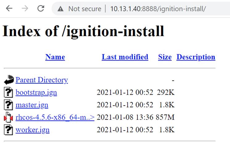
1. On Cisco UCS vKVM (Virtual KVM) console browse to RHCOS iso image and map the drive.
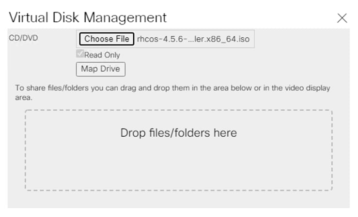
2. On the RHCOS Installer screen, press tab for full configuration options.
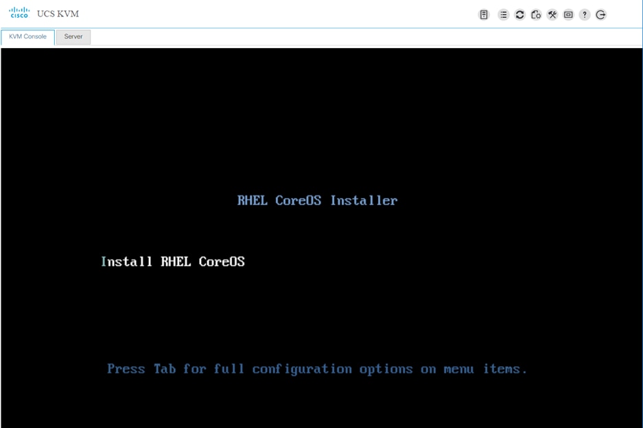
3. Add the following parameters to the kernel command line:
coreos.inst=yes coreos.inst.install_dev=sda ip=10.13.1.44::10.13.1.1:255.255.255.0:bootstrap.ocp4.hdp3.cisco.local:enp63s0:none nameserver=10.13.1.7 coreos.inst.image_url=http://10.13.1.31/ignition-install/rhcos-4.5.6-x86_64-metal.x86_64.raw.gz coreos.inst.ignition_url=http://10.13.1.31/ignition-install/bootstrap.ign
![]() Make sure above parameters should be supplied in one line (means no enter key).
Make sure above parameters should be supplied in one line (means no enter key).
![]() Pay attention to the syntax of IP address. It should be in the format of Syntax for the static ip is: ip=$IPADDR::$DEFAULTGW:$NETMASK:$HOSTNAME:$INTERFACE:none:$DNS or for DHCP it is: ip=dhcp
Pay attention to the syntax of IP address. It should be in the format of Syntax for the static ip is: ip=$IPADDR::$DEFAULTGW:$NETMASK:$HOSTNAME:$INTERFACE:none:$DNS or for DHCP it is: ip=dhcp
![]() If you are providing DNS name for image_url and ignition_url, make sure when coreos iso boots up, it is able to resolve it; this means your DHCP set the nameserver you are using or instead specify as static
If you are providing DNS name for image_url and ignition_url, make sure when coreos iso boots up, it is able to resolve it; this means your DHCP set the nameserver you are using or instead specify as static
4. The command line can be copy and paste from the clipboard:
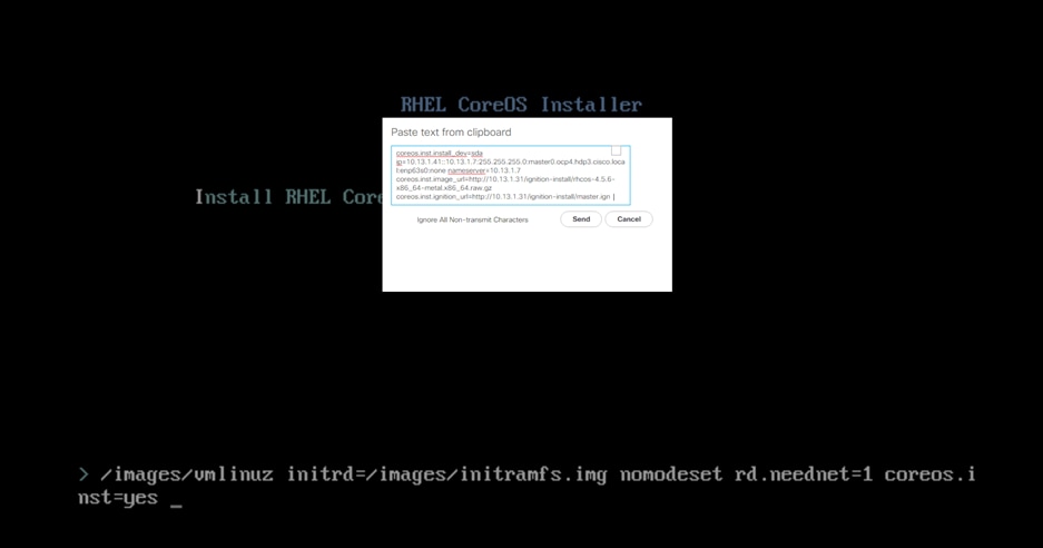
5. System will reboot automatically after successful OS installation:
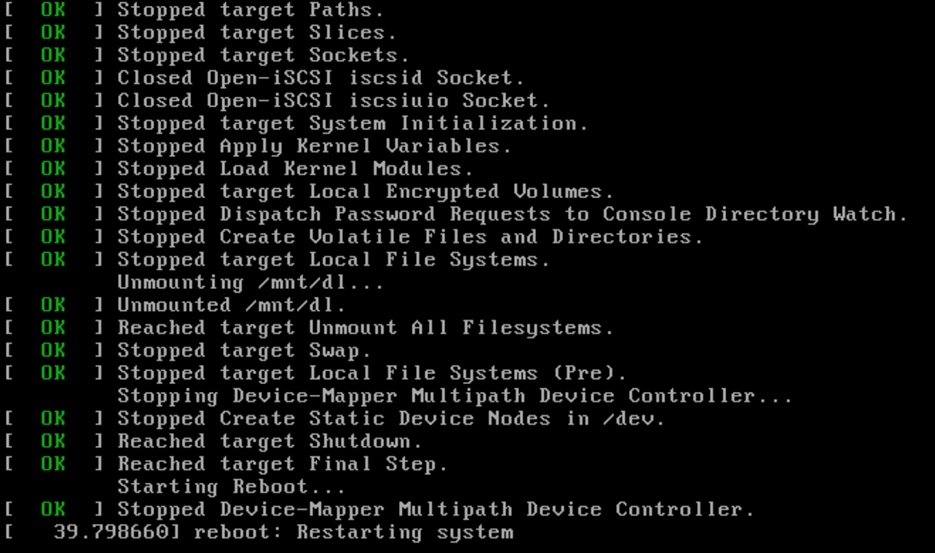
6. If the RHCOS install did not go through as a result of typo or providing incorrect values for parameters. You can perform the following as shown in figure once the system boots up with iso. This requires manual reboot after the install. Make sure to unmount the media in UCSM KVM before starting the reboot.
/usr/libexec/coreos-installer -d sde -b http://10.13.1.31/ignition-install/rhcos-4.5.6-x86_64-metal.x86_64.raw.gz -i http://10.13.1.31/ignition-install/master.ign
Figure 32. Coreos-installer Commandline Example
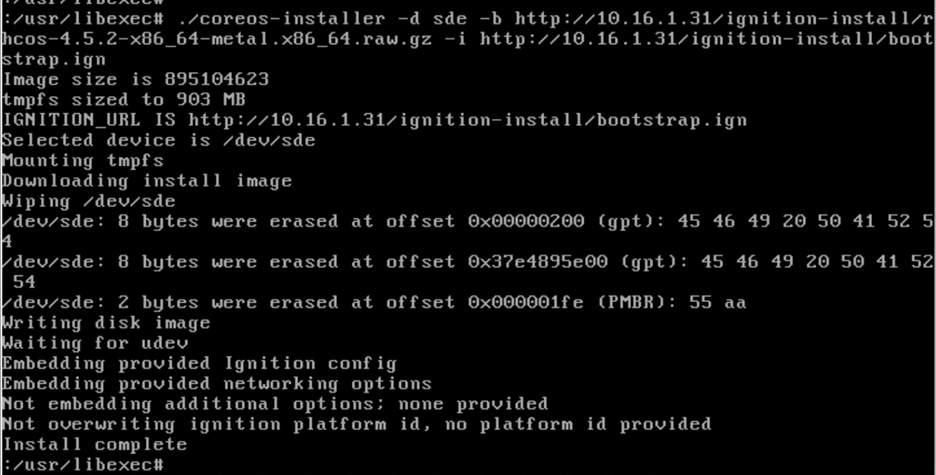
7. Repeat steps 1 – 6 for all master and worker nodes with their corresponding ignition file.
8. Login to bootstrap node after reboot:
# cd /root/ocp-install/
# eval "$(ssh-agent -s)"
# ssh-add installer
# ssh core@bootstrap.ocp4.hdp3.cisco.local
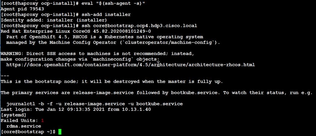
Monitor the Installation
When the bootstrap server is up and running, the installation is actually already in progress. First the masters "check in" to the bootstrap server for its configuration. After the masters are done being configured, the bootstrap server "hands off" responsibility to the masters. You can track the bootstrap process with the following command:
[root@bastion ocp-install]# ./openshift-install wait-for bootstrap-complete --log-level debug
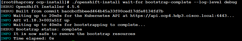
You can monitor the detailed installation progress by SSH to bootstrap node and run the following command:
[root@bastion ocp-install]# ssh core@bootstrap.ocp4.sjc02.lab.cisco.com
[root@bastion ocp-install]# journalctl -b -f -u release-image.service -u bootkube.service
![]() After bootstrap process is complete, remove the bootstrap machine from the load balancer.
After bootstrap process is complete, remove the bootstrap machine from the load balancer.
![]() For more information about commonly known issue and troubleshoot installation issues, go to: https://docs.openshift.com/container-platform/4.5/installing/installing-troubleshooting.html
For more information about commonly known issue and troubleshoot installation issues, go to: https://docs.openshift.com/container-platform/4.5/installing/installing-troubleshooting.html
Log into the Cluster
Log in to the cluster as a default system user by exporting the cluster kubeconfig file. The kubeconfig file contains information about the cluster that is used by the CLI to connect a client to the correct cluster and API server. The file is specific to a cluster and is created during OpenShift Container Platform installation.
To log into the cluster, follow these steps:
9. Export the kubeadmin credentials:
[root@bastion ocp-install]# export KUBECONFIG=auth/kubeconfig
10. Verify ability to run oc command:
[root@bastion ocp-install]# oc get nodes
[root@bastion ocp-install]# oc get pods --all-namespaces
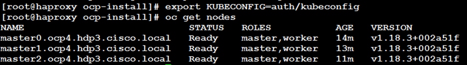
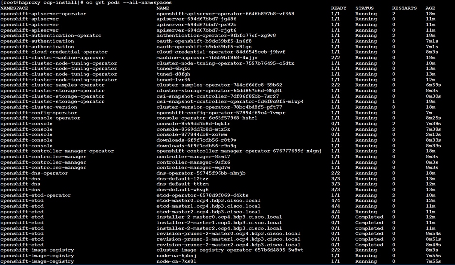
Approve Certificate Signing Requests for Machines
When you add machine(s) to a cluster, two pending certificate signing requests (CSRs) are generated for each machine that you added. You must confirm that these CSRs are approved or, if necessary, approve them yourself. The client requests must be approved first, followed by the server requests.
To approve the certificate signing requests for your machines, follow these steps:
1. Confirm that the cluster recognizes the machines. The output lists all of the machines added in the cluster:
[root@bastion ocp-install]# oc get nodes
2. Review the pending CSRs and ensure that you see the client requests with the Pending or Approved status for each machine that you added to the cluster:
[root@bastion ocp-install]# oc get csr
3. If the CSRs were not approved, after all of the pending CSRs for the machines you added are in Pending status, approve the CSRs for your cluster machines:
![]() Since the CSRs rotate automatically, approve your CSRs within an hour of adding the machines to the cluster. If you do not approve them within an hour, the certificates will rotate, and more than two certificates will be present for each node. You must approve all of these certificates. After you approve the initial CSRs, the subsequent node client CSRs are automatically approved by the cluster kube-controller-manager. You must implement a method of automatically approving the kubelet serving certificate requests.
Since the CSRs rotate automatically, approve your CSRs within an hour of adding the machines to the cluster. If you do not approve them within an hour, the certificates will rotate, and more than two certificates will be present for each node. You must approve all of these certificates. After you approve the initial CSRs, the subsequent node client CSRs are automatically approved by the cluster kube-controller-manager. You must implement a method of automatically approving the kubelet serving certificate requests.
4. To approve all pending CSRs, run the following command:
[root@bastion ocp-install]# oc get csr -o name
[root@bastion ocp-install]# oc get csr -o name | xargs oc adm certificate approve
![]() Follow steps 1-4 for every node added in the cluster and approval of the certificate signing request. For more information on CSRs, see Certificate Signing Requests.
Follow steps 1-4 for every node added in the cluster and approval of the certificate signing request. For more information on CSRs, see Certificate Signing Requests.
Access Web Console
The OpenShift Container Platform web console is a user interface accessible from a web browser. Developers can use the web console to visualize, browse, and manage the contents of projects.
The web console runs as a pod on the master. The static assets required to run the web console are served by the pod. When OpenShift Container Platform is successfully installed, find the URL for the web console and login credentials for your installed cluster in the CLI output of the installation program.
To access the web console, follow these steps:
1. To launch the web console, get the kubeadmin password. It is stored in ~/ocp-install/auth/kubeadmin-password:
[root@bastion auth]# # pwd
/root/ocp-install/auth
[root@bastion auth]# ls
kubeadmin-password kubeconfig
[root@bastion auth]# cat kubeadmin-password
2. Launch the OpenShift console by typing the following in the browser:
https://console-openshift-console.apps.ocp4.hdp3.cisco.local
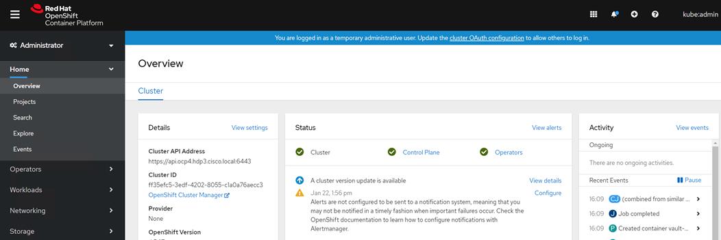
Deploy Portworx on OpenShift
Portworx is a software defined persistent storage solution designed and purpose built for applications deployed as containers, via container orchestrators such as Kubernetes, Marathon, and Swarm. It is a clustered block storage solution and provides a Cloud-Native layer from which containerized stateful applications programmatically consume block, file, and object storage services directly through the scheduler.
Below figure shows how worker nodes in OpenShift platform is configured with respect to disk allocated to be used in forming a Portworx cluster. It is also important to note that, in this setup, I’ll be using internal built-in key value database (KVDB). This requires minimum of three nodes to form key-value store (kvdb) cluster and nodes should be labelled as px-metadata-node=true. Optionally you can use label px/enabled=false if you do not want any specific node to be a part of Portworx cluster.
If you plan to use your own etcd cluster, please refer to the Portworx documentation. This document does not explain the Portworx deployment using external key-value store.
For complete list of prerequisites, go to: https://docs.portworx.com/start-here-installation/
Figure 33. Logical Architecture for Portworx
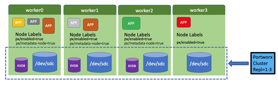
You can deploy Portworx on your internet-capable Kubernetes cluster using either the Operator or using the DaemonSet. In this CVD, we will be deploying Portworx using Portworx operator in OpenShift.
Install Portworx using Operator in OpenShift
Portworx operator is an easy way to deploy Portworx in OpenShift. It manages the overall lifecycle of Portworx cluster. With that, we can install, configure, update, and remove Portworx.
To install Portworx using Operator in OpenShift, follow these steps:
Figure 34 shows the components that makes up Portworx platform.
Figure 34. Kubernetes Cluster with Portworx Enterprise Operator
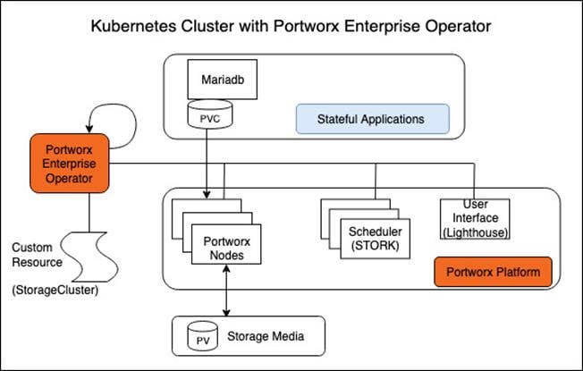
1. Login to OpenShift web console and navigate to OperatorHub. Search for Portworx as shown below:
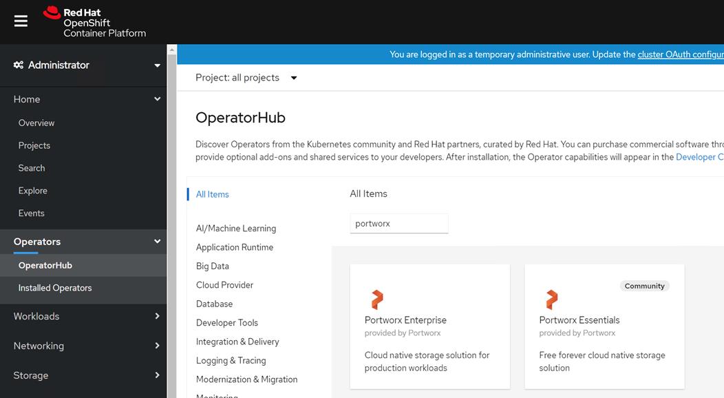
![]() We installed Portworx Enterprise. Portworx Essentials is a free version with limited capability such as up to 5 nodes, 5 TB of capacity, and 500 volumes. It is good enough for PoC purposes. However, for production grade setup, Portworx enterprise can be used. You can also give enterprise version a try with 30 days evaluation period.
We installed Portworx Enterprise. Portworx Essentials is a free version with limited capability such as up to 5 nodes, 5 TB of capacity, and 500 volumes. It is good enough for PoC purposes. However, for production grade setup, Portworx enterprise can be used. You can also give enterprise version a try with 30 days evaluation period.
2. Install Portworx Enterprise in kube-system namespace.
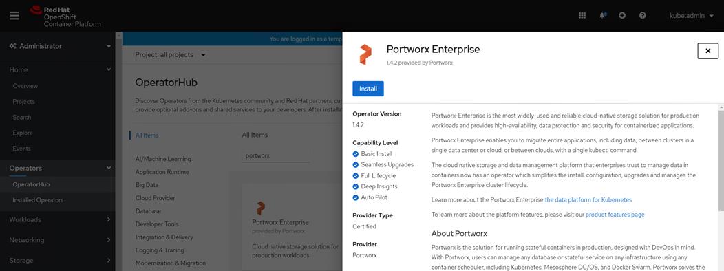
3. Wait for the operator pod to provision and change state from “running” to “Successes” as shown below:
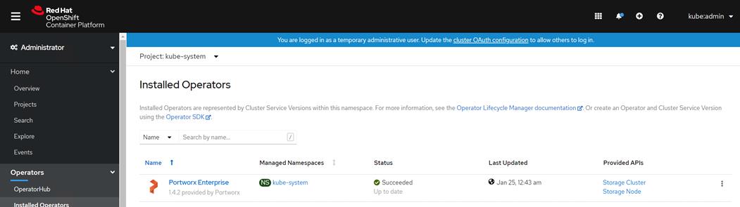
4. Navigate to Pods in kube-system project to verify the operator Pod is created and running.
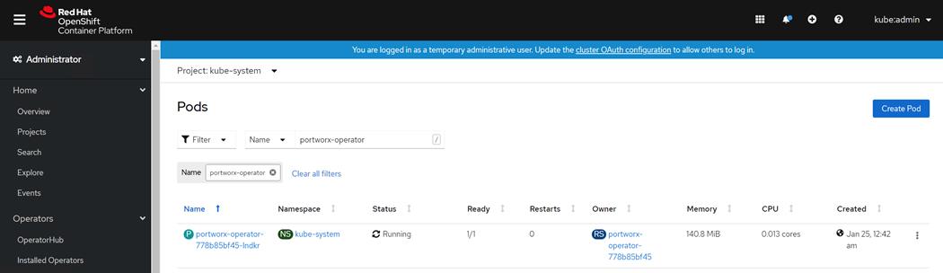
Installation Prerequisites
Storage Devices
It is recommended to use raw disk, no format and unmounted. If you encounter any issues such as KVDB is not creating, try the following:
Zero out and see if that resolves the issue. Make sure you uninstall Portworx with wipe option in yaml file for storage cluster in case if you have to uninstall:
# dd if=/dev/zero of=/dev/sdc bs=512 count=1
Open Ports
Portworx requires different open ports depending on how it’s installed:
● Spec-based installations require all Portworx nodes to have open TCP ports at 9001-9022 and an open UDP port at 9002.
● Portworx on OpenShift 4+ requires open TCP ports at 17001-17020 and an open UDP port at 17002.
Portworx also requires an open KVDB port. For example, if you’re using etcd externally, open port 2379.
If you intend to use Portworx with sharedv4 volumes, you may need to open your NFS ports.
If installing the Portworx Lighthouse management UI, open ports 32678 and 32679
Disable Swap
Disable swap on all nodes that will run the Portworx software. Ensure that the swap device is not automatically mounted on server reboot.
Label Nodes
Make sure to label nodes if you are using internal KVDB (Key Value Data Base). This requires minimum of three nodes to form key-value store (kvdb) cluster and nodes should be labelled as px/metadata-node=true. Optionally you can use label px/enabled=false if you do not want any specific node to be a part of Portworx cluster
![]() We used a built-in internal KVDB in this setup. The KVDB device provided needs to be present only on three of your nodes.
We used a built-in internal KVDB in this setup. The KVDB device provided needs to be present only on three of your nodes.
Use the following command to label OpenShift worker nodes that will be used for KVDB device:
# kubectl label nodes worker0.ocp4.hdp3.cisco.local px/metadata-node=true
# kubectl label nodes worker1.ocp4.hdp3.cisco.local px/metadata-node=true
# kubectl label nodes worker3.ocp4.hdp3.cisco.local px/metadata-node=true
#
Generate Portworx specs in PX-Central
The Portworx Enterprise Operator takes a custom Kubernetes resource called StorageCluster as input. The StorageCluster is a representation of your Portworx cluster configuration. Once the StorageCluster object is created, the Operator will deploy a Portworx cluster corresponding to the specification in the StorageCluster object. The Operator will watch for changes on the StorageCluster and update your cluster according to the latest specifications.
For more information about the StorageCluster object and how the Operator manages changes, refer to StorageCluster.
To install Portworx with OpenShift, follow these steps:
1. Generate the StorageCluster spec with the Portworx spec generator tool.
2. Select version of Portworx.
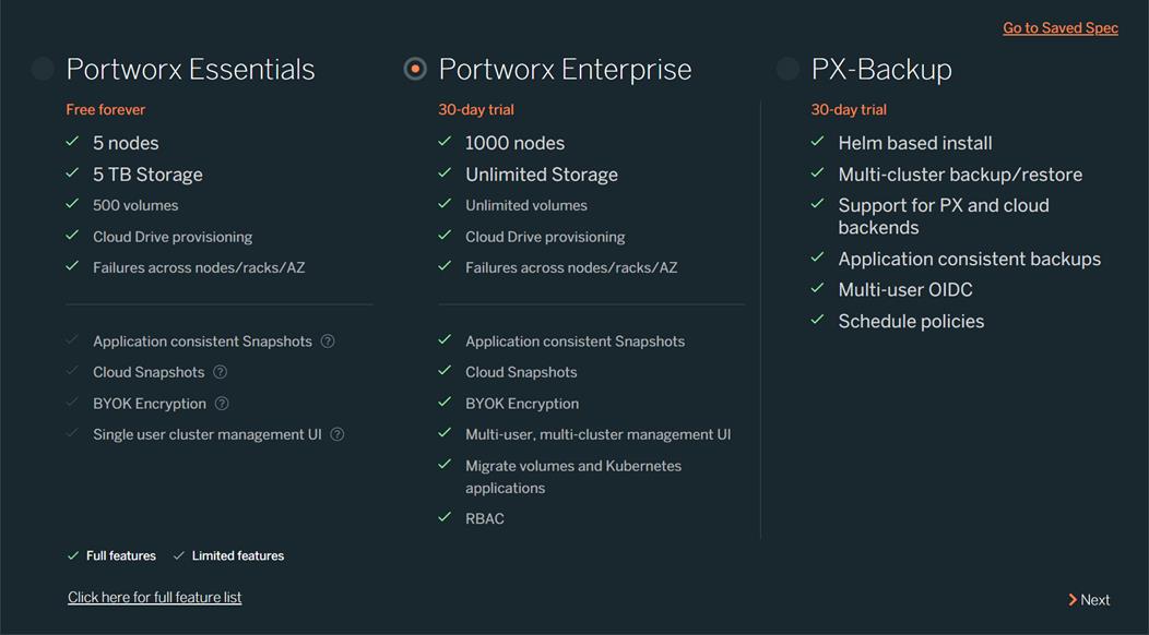
![]() In this CVD, we selected Portworx Enterprise.
In this CVD, we selected Portworx Enterprise.
3. Within the Portworx Operator page, select Create Instance to create a StorageCluster object.
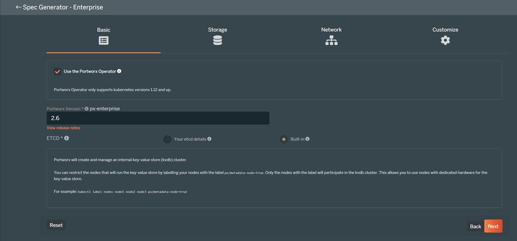
![]() Portworx requires a key-value database such as etcd for configuring storage. A highly available clustered etcd with persistent storage is preferred for production grade environment.
Portworx requires a key-value database such as etcd for configuring storage. A highly available clustered etcd with persistent storage is preferred for production grade environment.
![]() Select the Built-in option to deploy Portworx with internal KVDB
Select the Built-in option to deploy Portworx with internal KVDB
4. Click On Premises then click Manually specify disk. In this example, we will be dedicating four disks, for example /dev/sdb, /dev/sdc, /dev/sdd, /dev/sde for Portworks. You can specify more disks by clicking + sign. For simplicity, we used “Auto create journal device” and skipped “KVDB device”. You can specify a dedicated KVDB device such as /dev/sdd or so to separate KVDB I/O with storage I/O.
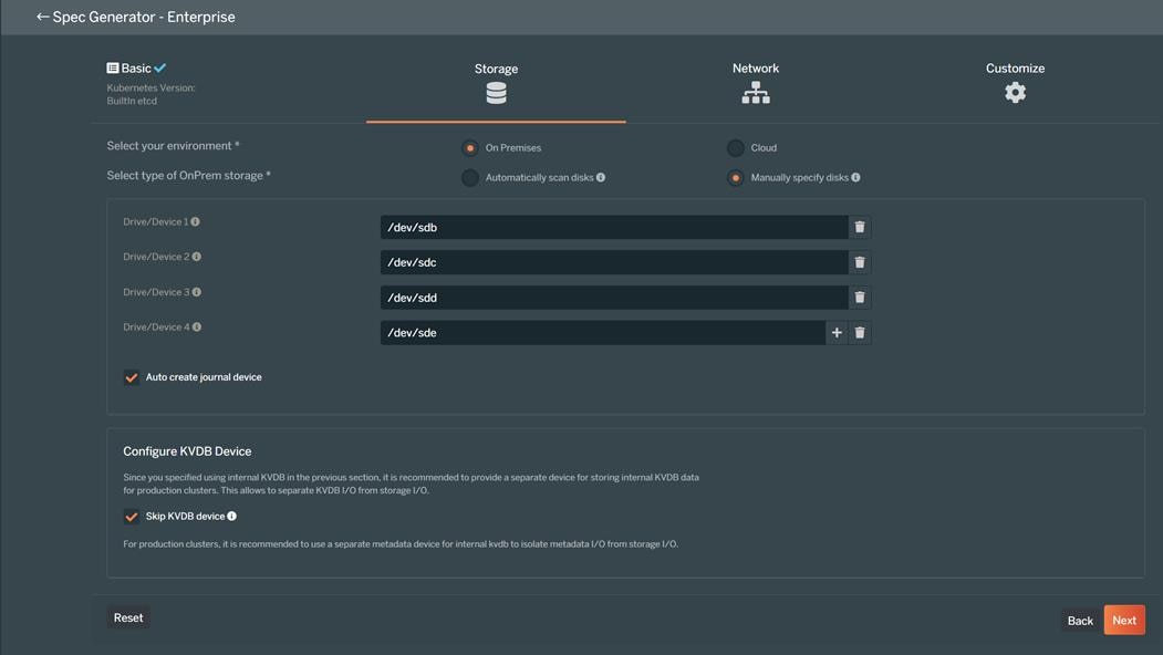
![]() In this CVD, we auto-created a journal device. However, it is recommended to use a journal device to absorb Portworx metadata writes. Journal writes are small with frequent syncs and therefore SSD/NVME should be considered as a journal device. If the journal device is slower than the actual storage drive, your overall performance will be lower and match the lower of two devices.
In this CVD, we auto-created a journal device. However, it is recommended to use a journal device to absorb Portworx metadata writes. Journal writes are small with frequent syncs and therefore SSD/NVME should be considered as a journal device. If the journal device is slower than the actual storage drive, your overall performance will be lower and match the lower of two devices.
![]() For production clusters, it is recommended to use a separate metadata device for internal KVDB to isolate metadata I/O from storage I/O.
For production clusters, it is recommended to use a separate metadata device for internal KVDB to isolate metadata I/O from storage I/O.
5. On the Network page keep all default settings.
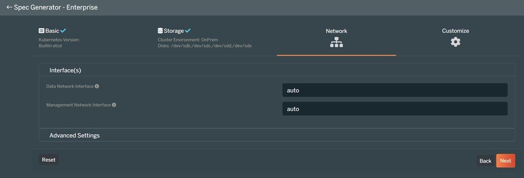
6. On customize screen, select OpenShift 4+ as shown below:

7. Click Finish. Accept Portworx the license agreement.
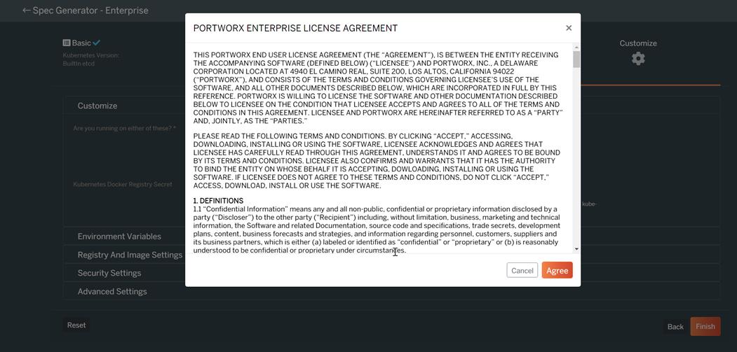
8. Download the spec file by providing a name. this will give you a .yaml file for provisioning storage cluster.
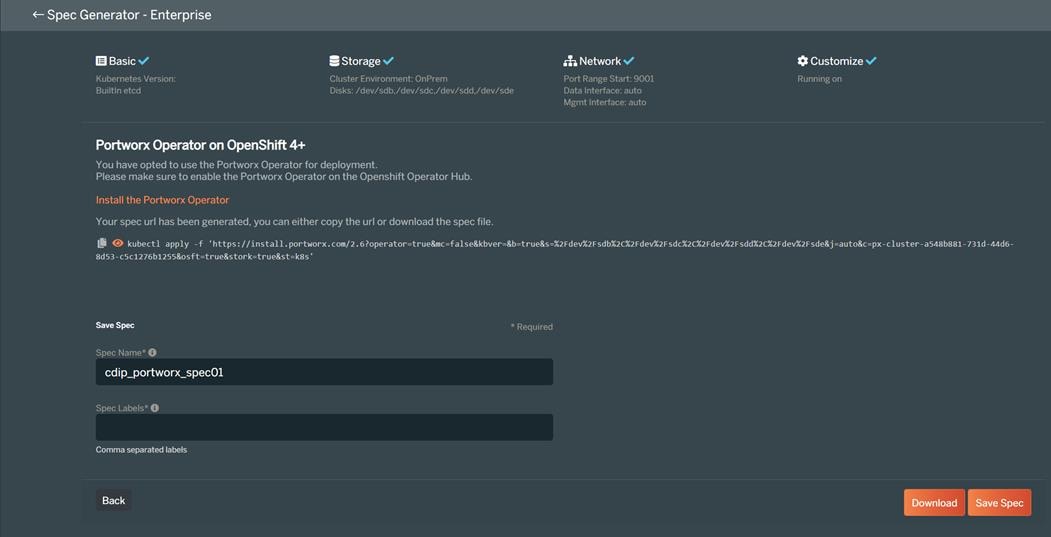
9. For Portworx Essentials cluster, create the following secret with your Essential Entitlement ID:
kubectl -n kube-system create secret generic px-essential \
--from-literal=px-essen-user-id=YOUR_ESSENTIAL_ENTITLEMENT_ID \
--from-literal=px-osb-endpoint='https://pxessentials.portworx.com/osb/billing/v1/register'
Create Storage Cluster
To create a storage cluster, follow these steps:
1. Apply the spec using the following command:
[root@bastion ocp-install]# oc apply -f cdip_portworx_spec01.yaml
2. Or it can be installed directly from portworx.com. this is generated for you at the time of creating spec for storage cluster:
Kubectl apply -f ‘https://install.portworx.com/?operator=true&mc=false&kbver=&b=true&s=%2Fdev%2Fsdb%2C%2Fdev%2Fsdc%2C%2Fdev%2Fsdd&j=auto&c=px-cluster-1cc49e97-ad8e-4a82-a2df-298a5a57ae02&osft=true&stork=true&st=k8s’
3. Pods will start to provision in kube-system namespace as shown below. Make sure all Pods eventually gets into “Running” status.
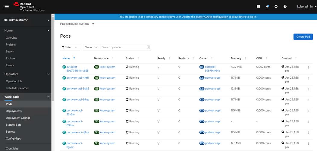
4. Verify that Portworx has deployed successfully by navigating to the Storage Cluster tab of the Installed Operators page. When Portworx has fully deployed, the status will show as Online.
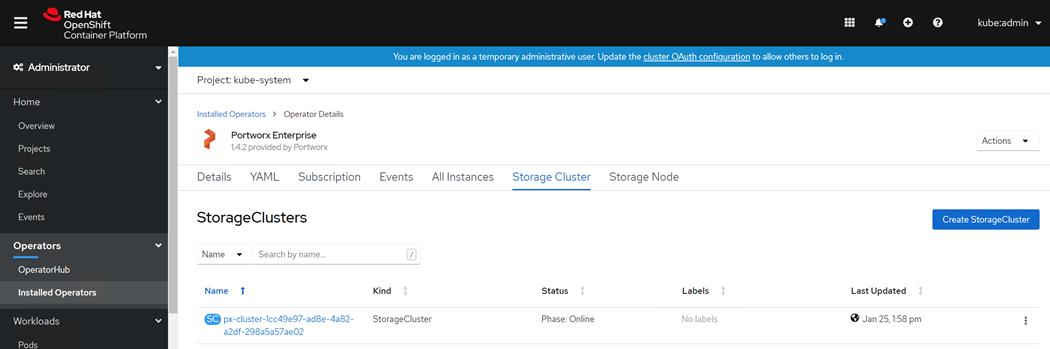
5. Validate by running the following to see if you have it installed correctly and successfully. Verify that all Pods in kube-system namespace are up and running:
[root@bastion ocp-install]# oc get pods -n kube-system
6. Check the status of the cluster Pods. Since we used sixteen worker nodes to participate in forming Portworx cluster, there are sixteen cluster Pods. You can verify each one of them by running the following command:
[root@bastion ocp-install]# oc exec <px-cluster-1cc49e97-ad8e-4a82-a2df-298a5a57ae02-pvsht> -n kube-system -- /opt/pwx/bin/pxctl status
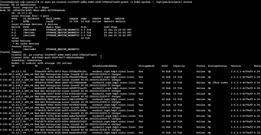
7. The same can be verified from Pod terminal in RHOCP web console.
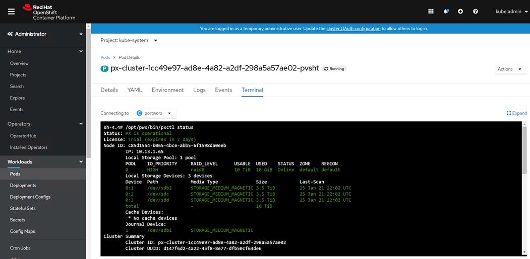
Provision Volumes
When you provision volumes, Portworx places them throughout the cluster and across configured failure domains to provide fault tolerance. For more details on various storage operations, go to: https://docs.portworx.com/portworx-install-with-kubernetes/storage-operations/
Create Storage Classes
To create storage classes, follow these steps:
1. In RHOCP web console, click Storage > Storage Classes. Click Create Storage Class.
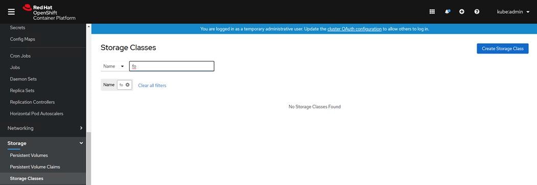
2. Enter required filled and click Edit YAML.
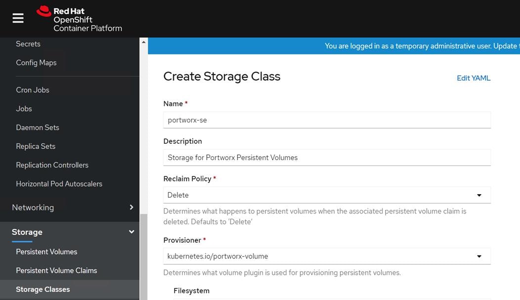
3. Enter the following:
apiVersion: storage.k8s.io/v1
kind: StorageClass
metadata:
name: example
provisioner: my-provisioner
reclaimPolicy: Delete
parameters:
repl: "1"
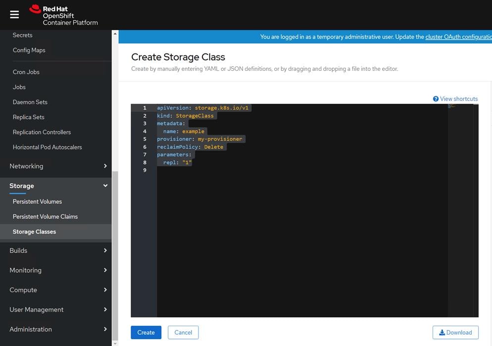
4. Click Create.
5. Storage class can also be created by saving the above yaml file and run the following:
[root@bastion ocp-install]# kubectl create -f examples/volumes/portworx/portworx-sc.yaml
[root@bastion ocp-install]# kubectl describe storageclass portworx-sc
Name: portworx-sc
IsDefaultClass: Yes
Annotations: storageclass.kubernetes.io/is-default-class=true
Provisioner: kubernetes.io/portworx-volume
Parameters: repl=3
AllowVolumeExpansion: <unset>
MountOptions: <none>
ReclaimPolicy: Delete
VolumeBindingMode: Immediate
Events: <none>
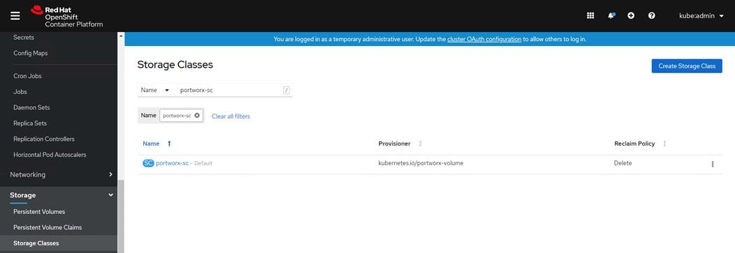
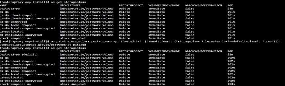
Create Persistent Volume Claim
To create a persistent volume claim, follow these steps:
6. Use the following yaml file and save it as portworx-volume-pvcsc.yaml:
kind: PersistentVolumeClaim
apiVersion: v1
metadata:
name: pvcsc001
annotations:
volume.beta.kubernetes.io/storage-class: portworx-sc
spec:
accessModes:
- ReadWriteOnce
resources:
requests:
storage: 2Gi
7. Run the following command:
[root@bastion ocp-install]# kubectl create -f portworx-volume-pvcsc.yaml
8. You can create the same in the GUI by clicking Persistent Volume Claim and copy and paste the above YAML:
[root@bastion ocp-install# kubectl describe pvc pvcsc001 -n kube-system
Name: pvcsc001
Namespace: kube-system
StorageClass: portworx-sc
Status: Bound
Volume: pvc-520ee286-309e-4086-95eb-729dce7833e4
Labels: <none>
Annotations: pv.kubernetes.io/bind-completed: yes
pv.kubernetes.io/bound-by-controller: yes
volume.beta.kubernetes.io/storage-class: portworx-sc
volume.beta.kubernetes.io/storage-provisioner: kubernetes.io/portworx-volume
Finalizers: [kubernetes.io/pvc-protection]
Capacity: 2Gi
Access Modes: RWO
VolumeMode: Filesystem
Mounted By: pvpod
Events: <none>
Create Pod using Persistent Volume Claim with Storage Class
To create a pod using a persistent volume claim with storage class, follow these steps:
1. Create a portworx-volume-pvcscpod.yaml with the following content:
apiVersion: v1
kind: Pod
metadata:
name: pvpod
spec:
containers:
- name: test-container
image: gcr.io/google_containers/test-webserver
volumeMounts:
- name: test-volume
mountPath: /test-portworx-volume
volumes:
- name: test-volume
persistentVolumeClaim:
claimName: pvcsc001 wo
2. Create POD by running the following command:
[root@bastion ocp-install# kubectl create -f portworx-volume-pvcscpod.yaml
Install CDP Private Cloud Experiences
Review the installation requirements and core tasks for installing CDP Private Cloud. CDP Private Cloud Experiences works on top of CDP Private Cloud Base and is the on-premise offering of CDP that brings many of the benefits of the public cloud deployments to the on-premise CDP deployments. CDP Private Cloud Experiences lets you deploy and use the Cloudera Data Warehouse (CDW) and Cloudera Machine Learning (CML) experiences.
You must install CDP Private Cloud Experiences on an existing deployment of CDP Private Cloud Base. To install CDP Private Cloud, you need an isolated hardware environment with dedicated infrastructure and networking. CDP Private Cloud Experiences uses containers on the Red Hat OpenShift Container Platform.
CDP Private Cloud Base provides the following components and services that are used by CDP Private Cloud Experiences:
● SDX Data Lake cluster for security, metadata, and governance
● HDFS or Ozone for storage
● Cloudera Runtime components such as Ranger, Atlas, and Hive Metastore (HMS)
● Networking infrastructure that supports network traffic between storage and compute environments
Before you get started with the CDP PC Experiences installation, please review the Hardware and Software requirements and the Pre-Installation Checklist.
To install CDP Private Cloud, follow these steps:
1. Log into Cloudera Manager WebUI <https://FQDN_or_IP>:7183/. Click the Private Cloud in the left pane. This will open the Private Cloud installation wizard. This wizard will walk you through the steps to install CDP PC.
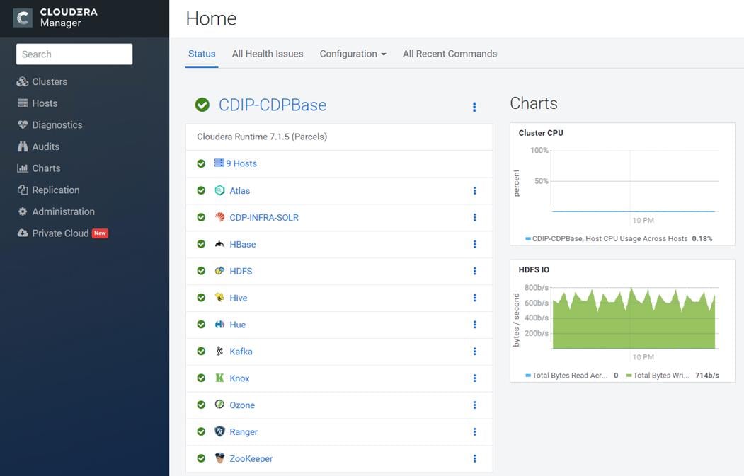
2. On the Getting Started page, select the repository that contains the installer. Select Repository field is pre-populated with Cloudera download location. If you have setup custom repository, it can also be chosen. In the deployment, we have used pre-populated location.
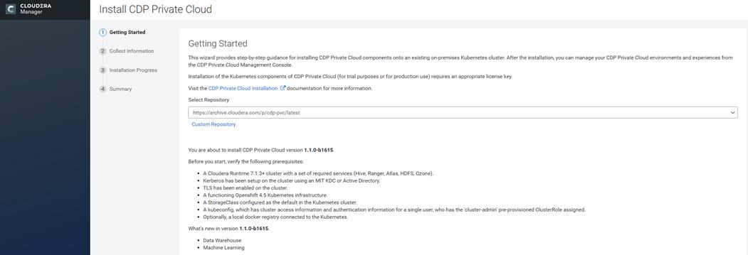
3. After selecting the repository, the installation wizard displays a list of prerequisites for the Private Cloud version that you are installing. Use the following worksheet to meet the prerequisites.
| Collect Information |
Parameters |
Notes |
| Kubernetes Configuration |
kubeconfig |
Click Choose File to upload kubeconfig file generated by OpenShift install. This kubeconfig file can be found in bastion node in auth folder |
| Kubernetes Namespace |
cdp |
Provide a name for CDP PC control plane. This would reflect as a Project in OpenShift cluster |
| Configure Docker Registry |
Use Cloudera’s default Docker Repository |
In this deployment, we are not setting up custom Docker Repository for downloading CDP private cloud images. |
| Configure Databases |
Create embedded databases |
In this deployment guide, we used embedded databases which will create PostgreSQL database container in OpenShift environment with persistent volume provided by Portworx. However existing PostgreSQL with version 10.6 or higher is recommended for production environment. |
| Embedded Database Disk Space (GiB) |
200 |
Space allocated for embedded PostgreSQL. Default value is 200 GiB. |
| Configure Vault |
Embedded vault |
Vault is a secret management tool. With embedded vault, installer will create a separate project (Namespace) in RHOCP environment for secret management. Already existing or external vault can also be utilized; however, it is beyond the scope of the guide. External vault is recommended solution for production grade environment |
| Storage Class |
portwrox-sc |
Name of storage class created in RHOCP and configured with portworx. This is required to provision persistent volumes for CDP PC control plane. |
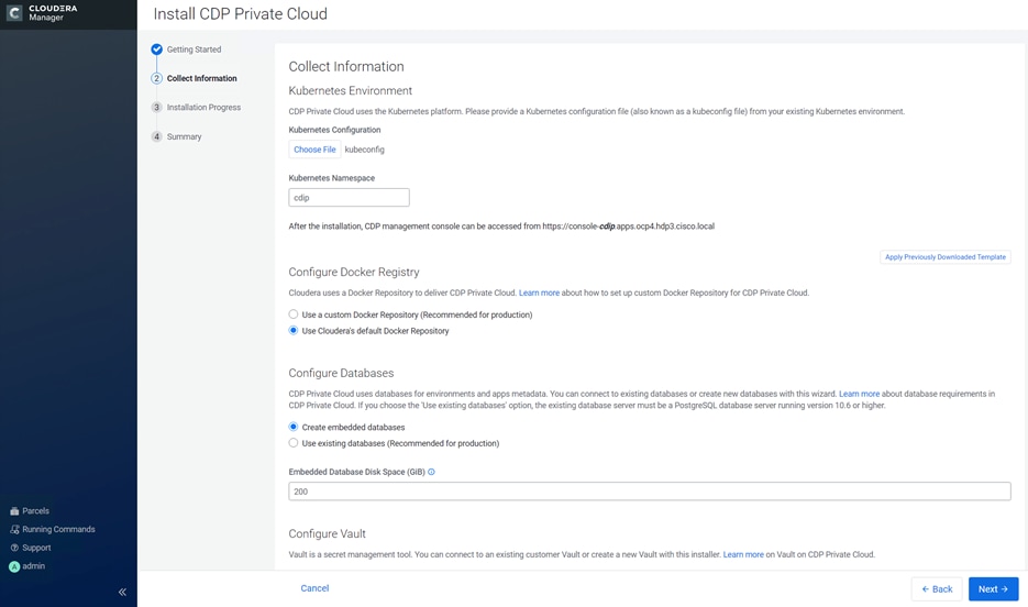
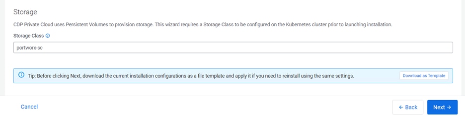
4. Click Next to install private cloud.
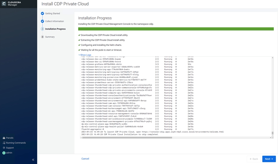
5. Click Launch CDP Private Cloud.
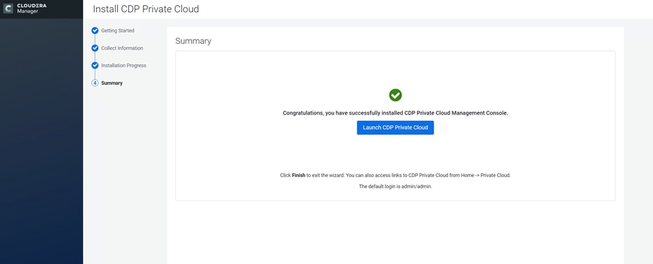
6. Login as local administrator; default username and password is admin/admin.
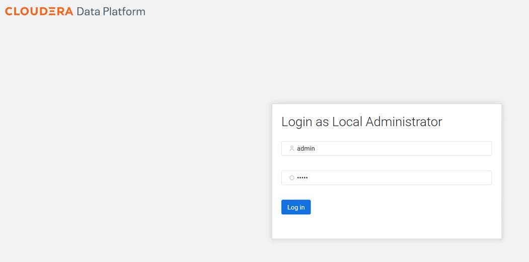
7. Select Change Password. Enter New Password.
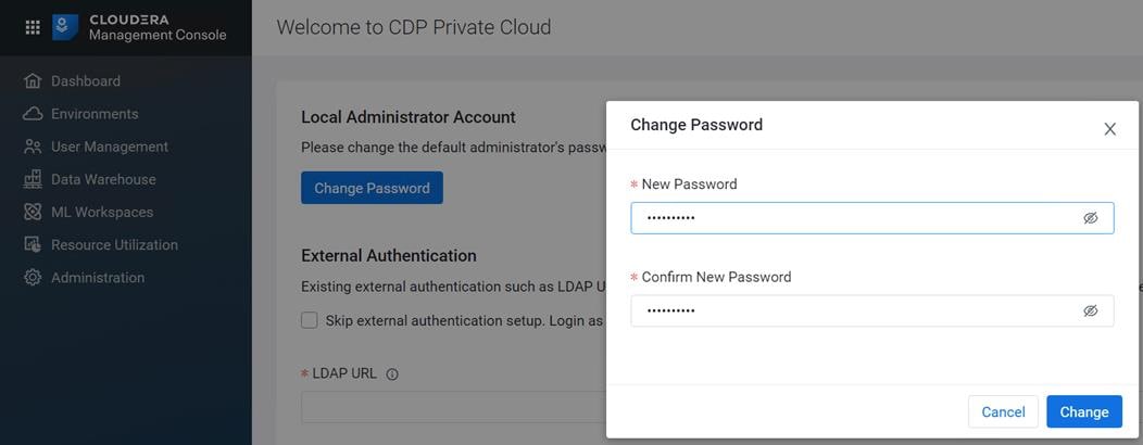
8. In this CVD, we skipped the external authentication. Click Test Connection then click Next.
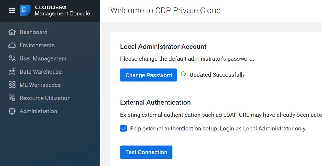
Register Environment
In CDP, a private cloud environment is an association between a data lake and multiple compute resources.
![]() You can register as many environments as you require.
You can register as many environments as you require.
An environment is a local construct that groups resources such as Machine Learning workspaces or Data Warehouse warehouses within a data center or cloud region. Each environment talks to one SDX residing in a base cluster. For private cloud environments, resources include compute clusters such as Kubernetes as well as Data Lake clusters in CDP. These resources typically reside within the same physical location to minimize network latencies between compute and storage. Compute workloads are deployed within these environments.
A workload receives access to a Kubernetes cluster for compute purposes and a Data Lake cluster for storage, metadata, and security purposes within the environment in which it is deployed. Admins can define user permissions and set resource quotes in each environment.
To register environment, follow these steps:
1. In Cloudera Management Console, click Environments.
2. Enter Environment Name, Kubernetes Configuration file, Storage Class, Domain, Cloudera Manager URL and admin user and password.
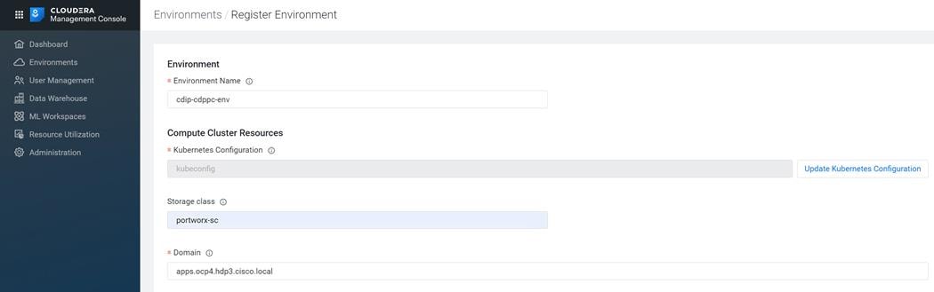
3. Click Test connection. Click on Register after successful connection.
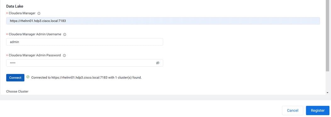
![]() If you don't have HDFS, Hive Metastore, Ranger, and Atlas services installed on data lake, environment will not register. Make sure you meet the minimum requirement for data lake.
If you don't have HDFS, Hive Metastore, Ranger, and Atlas services installed on data lake, environment will not register. Make sure you meet the minimum requirement for data lake.
4. Select the registered environment and select Data Lake tab to view details about Data Lake.
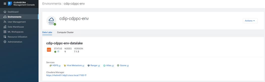
5. Click Compute Cluster tab to view OpenShift environment details.
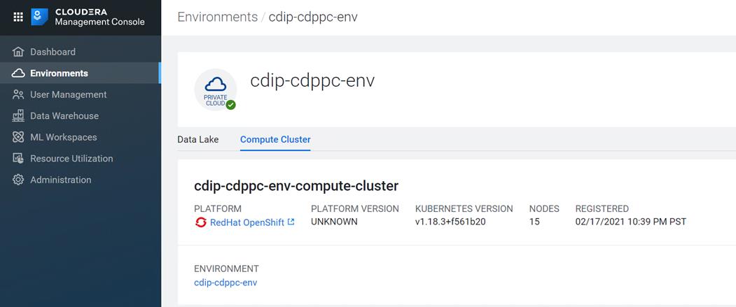
Provision Workspace for Cloudera Machine Learning (CML)
Cloudera Machine Learning (CML) is Cloudera’s new cloud-native machine learning service, built for CDP. The CML service provisions clusters, also known as ML workspaces, that run natively on Kubernetes.
To provision a workspace for CML, follow these steps:
1. In Cloudera Private Cloud Management console click Machine Learning.
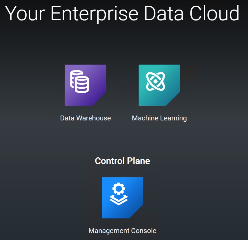
2. Click Provision Workspace.
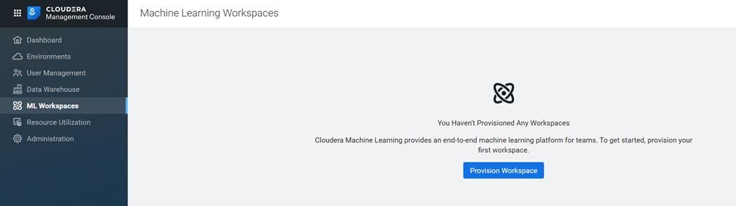
3. Enter namespace, workspace, internal or external NFS Share and select environment. Click Provision Workspace.
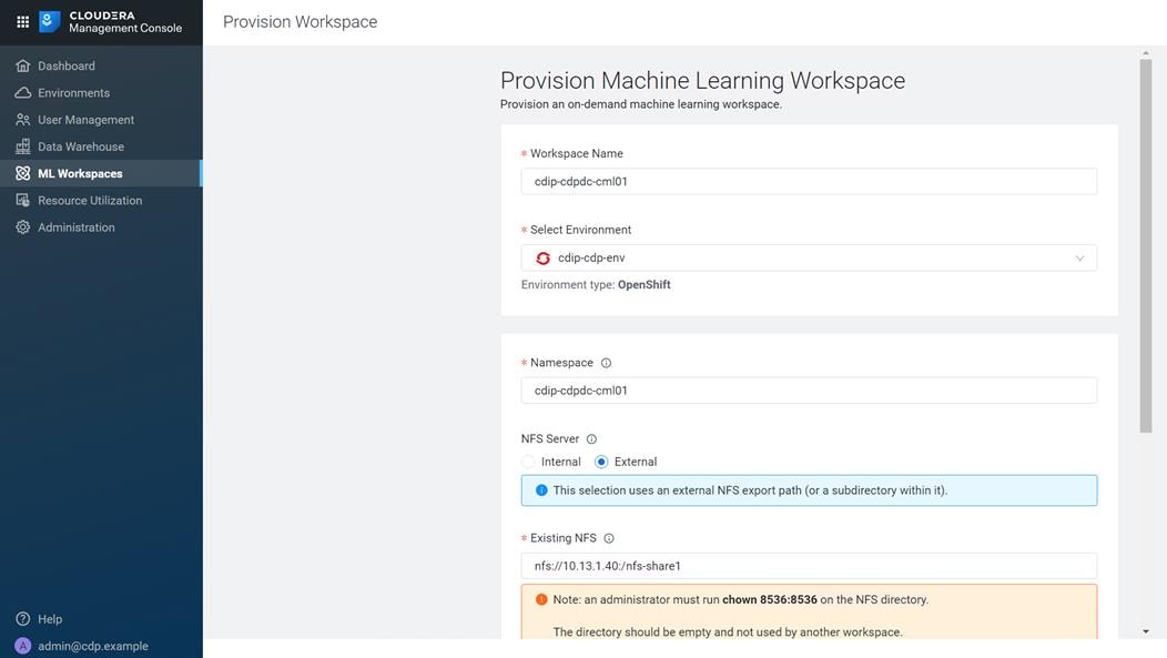
![]() NFS is a requirement for provisioning machine learning workspace. Setting up NFS is beyond the scope of this document. NFS share is used for storing project files for CML workspace. Each CML workspace requires NFS share.
NFS is a requirement for provisioning machine learning workspace. Setting up NFS is beyond the scope of this document. NFS share is used for storing project files for CML workspace. Each CML workspace requires NFS share.
![]() For lab purpose and for the sake of simplicity, we installed and setup NFS server on RHEL bare metal server and exported the file system for remote access. NFS is already setup in many enterprises in some form or the other and it can also be utilized for this purpose as long as it is accessible from private cloud and RHOCP.
For lab purpose and for the sake of simplicity, we installed and setup NFS server on RHEL bare metal server and exported the file system for remote access. NFS is already setup in many enterprises in some form or the other and it can also be utilized for this purpose as long as it is accessible from private cloud and RHOCP.
![]() It is recommended to use Kubernetes internal NFS. Internal NFS provides cloud like experience and NFS backed persistent volume lifecycle is managed by K8. This can be implemented with dynamic NFS provisioning within RHOCP environment. Persistent volume with NFS lets you setup a managed resource within the cluster which is accessed via the NFS.
It is recommended to use Kubernetes internal NFS. Internal NFS provides cloud like experience and NFS backed persistent volume lifecycle is managed by K8. This can be implemented with dynamic NFS provisioning within RHOCP environment. Persistent volume with NFS lets you setup a managed resource within the cluster which is accessed via the NFS.
![]() To learn more about persistent storage using NFS in RHOCP, go to: https://docs.openshift.com/container-platform/4.5/storage/persistent_storage/persistent-storage-nfs.html
To learn more about persistent storage using NFS in RHOCP, go to: https://docs.openshift.com/container-platform/4.5/storage/persistent_storage/persistent-storage-nfs.html
4. After successful provisioning of workspace, status reports as “Ready”.
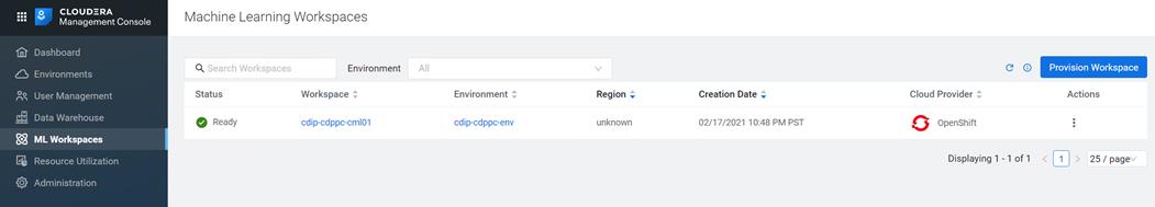
5. Click Navigate service icon next to workspace name “cdip-cdppc-cml01”
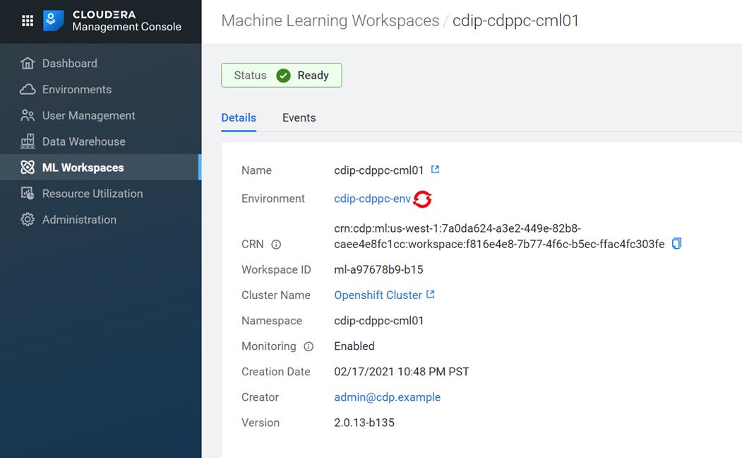
6. Create New Project.
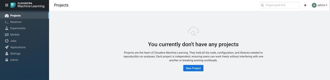
7. Enter Project Name, select visibility and initial setup.
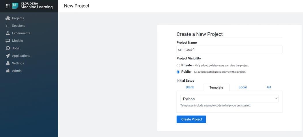
8. Click New Session.
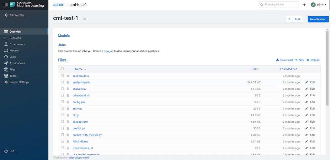
9. If asked enter details for Hadoop authentication. Click Settings > Hadoop Authentication. Without setting up Hadoop Authentication, you will not be able to access HDFS in CML.
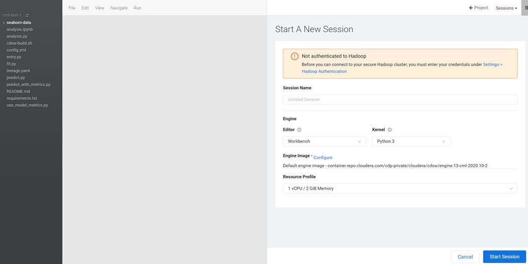
10. Provide credentials for Kerberos principal as shown below. In this example, we will be using the same bind user we used for setting up Kerberos in Cloudera Manager. However, a dedicated separate bind user can also be created in Active Directory.
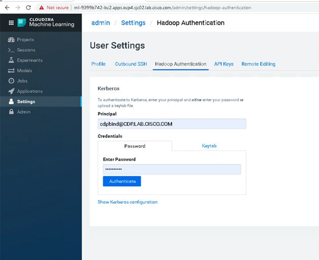
11. Click Authenticate for Kerberos authentication. If authentication is successful, following output displays.
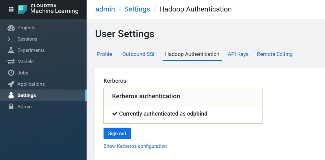
12. Click Start Session.
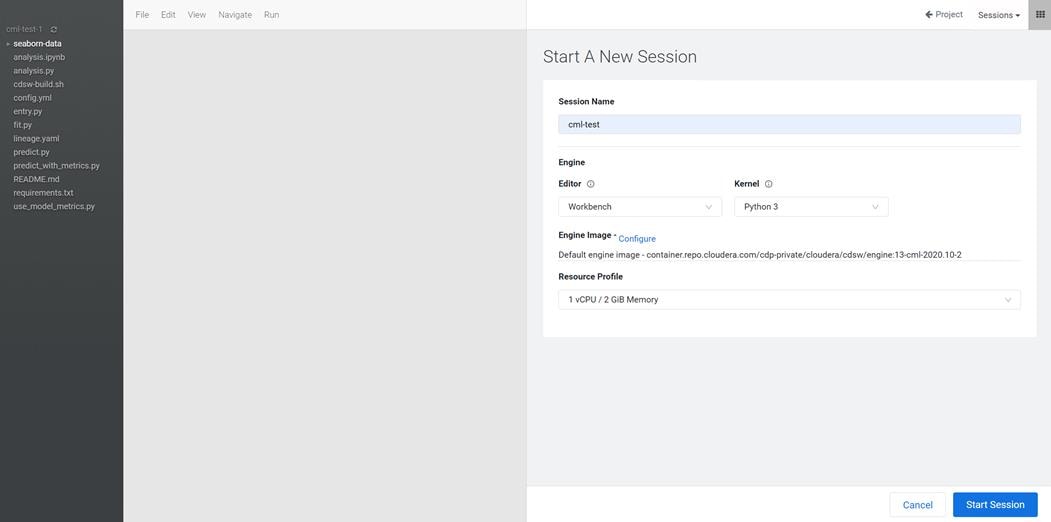
13. Create a new .py file by clicking FileàNew File. Type the following HDFS command and click Run to test the connection.
# Run sample HDFS commands
# Use any file in the project directory to be uploded in HDFS
!hdfs dfs -mkdir /tmp/testhdfs/
!hdfs dfs -copyFromLocal /home/cdsw/fit.py /tmp/testhdfs/
!hdfs dfs -cat /tmp/testhdfs/fit.py
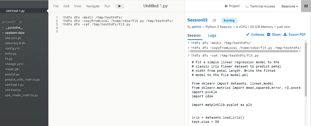
14. Select the analysis.py from the project folder and run the python script as shown below:
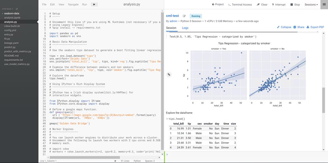
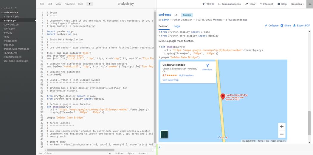
To provide a seamless operation of the application at this scale, you need the following:
● An infrastructure automation with centralized management
● Deep telemetry and simplified granular troubleshooting capabilities
● Multi-tenancy for application workloads, including containers and micro-services, with the right level of security and SLA for each workload
Cisco UCS with Cisco Intersight and Cisco ACI can enable this next-generation cloud-scale architecture, deployed and managed with ease while Cloudera Data Platform Private Cloud Experiences provides the software capabilities to tie these technologies together in a seamless and secure manner.
For additional information, see the following resources:
● To find out more about Cisco UCS Big Data solutions, visit https://www.cisco.com/go/bigdata
● To find out more about Cisco UCS Big Data validated designs, visit https://www.cisco.com/go/bigdata_design
● TO find out more about Cisco Data Intelligence Platform, see https://www.cisco.com/c/dam/en/us/products/servers-unified-computing/ucs-c-series-rack-servers/solution-overview-c22-742432.pdf
● To find out more about Cisco UCS AI/ML solutions, see http://www.cisco.com/go/ai-compute
● To find out more about Cisco ACI solutions, see http://www.cisco.com/go/aci
● To find out more about Cisco validated solutions based on Software Defined Storage, see https://www.cisco.com/c/en/us/solutions/data-center-virtualization/software-defined-storage-solutions/index.html
● Cloudera Data Platform Data Center 7.0 release note, see https://docs.cloudera.com/cdpdc/7.0/release-guide/topics/cdpdc-release-notes-links.html
● CDP Data Center Requirements and Supported Versions, see https://docs.cloudera.com/cdpdc/7.0/release-guide/topics/cdpdc-requirements-supported-versions.html
This section provides the Bill of Materials for the 28 Nodes Hadoop Base Rack.
Table 9. Bill of Material for Cisco UCS C240 M5SX CDP Base Cluster
| Part Number |
Description |
Qty |
| UCSC-C240-M5SX |
UCS C240 M5 24 SFF + 2 rear drives w/o CPU,mem,HD,PCIe,PS |
10 |
| CON-OSP-C240M5SX |
SNTC 24X7X4OS UCS C240 M5 24 SFF + 2 rear drives w/o CPU,mem |
10 |
| UCS-MR-X32G2RT-H |
32GB DDR4-2933-MHz RDIMM/2Rx4/1.2v |
120 |
| UCSC-RIS-1-240M5 |
Riser1 3PCIe slots(x8, x16, x8); slot3 req CPU2, For T4, RTX |
10 |
| UCSC-MLOM-C100-04 |
Cisco UCS VIC 1497 Dual Port 100G QSFP28 CNA mLOM |
10 |
| UCS-M2-240GB |
240GB SATA M.2 |
20 |
| UCS-M2-HWRAID |
Cisco Boot optimized M.2 Raid controller |
20 |
| UCSC-PSU1-1050W |
Cisco UCS 1050W AC Power Supply for Rack Server |
20 |
| CAB-9K12A-NA |
Power Cord, 125VAC 13A NEMA 5-15 Plug, North America |
20 |
| UCSC-RAILB-M4 |
Ball Bearing Rail Kit for C220 & C240 M4 & M5 rack servers |
10 |
| CIMC-LATEST |
IMC SW (Recommended) latest release for C-Series Servers. |
10 |
| UCS-SID-INFR-BD |
Big Data and Analytics Platform (Hadoop/IoT/ITOA/AI/ML) |
10 |
| UCS-SID-WKL-BD |
Big Data and Analytics (Hadoop/IoT/ITOA) |
10 |
| UCSC-HS-C240M5 |
Heat sink for UCS C240 M5 rack servers 150W CPUs & below |
20 |
| CBL-SC-MR12GM5P |
Super Cap cable for UCSC-RAID-M5HD |
10 |
| UCSC-PCIF-240M5 |
C240 M5 PCIe Riser Blanking Panel |
10 |
| UCSC-BBLKD-S2 |
UCS C-Series M5 SFF drive blanking panel |
220 |
| UCSC-SCAP-M5 |
Super Cap for UCSC-RAID-M5, UCSC-MRAID1GB-KIT |
16 |
| UCS-CPU-I5218R |
Intel 5218R 2.1GHz/125W 20C/27.5MB DDR4 2667MHz |
32 |
| UCSC-RAID-M5HD |
Cisco 12G Modular RAID controller with 4GB cache |
16 |
| UCS-HD24TB10K4KN |
2.4 TB 12G SAS 10K RPM SFF HDD (4K) |
240 |
| UCS-HD24TB10K4KN |
2.4 TB 12G SAS 10K RPM SFF HDD (4K) |
200 |
| UCSC-C240-M5SX |
UCS C240 M5 24 SFF + 2 rear drives w/o CPU,mem,HD,PCIe,PS |
10 |
| CON-OSP-C240M5SX |
SNTC 24X7X4OS UCS C240 M5 24 SFF + 2 rear drives w/o CPU,mem |
10 |
| RACK2-UCS2 |
Cisco R42612 standard rack, w/side panels |
1 |
| CON-SNT-RCK2UCS2 |
SNTC 8X5XNBD, Cisco R42612 standard rack, w side panels |
1 |
| UCS-SP-FI6332 |
(Not sold standalone) UCS 6332 1RU FI/12 QSFP+ |
2 |
| CON-OSP-SPFI6332 |
ONSITE 24X7X4 (Not sold standalone) UCS 6332 1RU FI/No PSU/3 |
2 |
| UCS-PSU-6332-AC |
UCS 6332 Power Supply/100-240VAC |
4 |
| UCS-FAN-6332 |
UCS 6332/ 6454 Fan Module |
4 |
| QSFP-H40G-CU3M |
Cisco 40GBASE-CR4 QSFP+ direct-attach copper cable, 3-meter, passive |
32 |
![]() For NameNode, we configured ten 1.8TB 10K RPM SAS HDD.
For NameNode, we configured ten 1.8TB 10K RPM SAS HDD.
Table 10. Bill of Material for Cisco UCS C240M5SX OCP Worker Nodes
| Part Number |
Description |
Qty |
| UCSC-C240-M5SX |
UCS C240 M5 24 SFF + 2 rear drives w/o CPU,mem,HD,PCIe,PS |
16 |
| CON-OSP-C240M5SX |
SNTC 24X7X4OS UCS C240 M5 24 SFF + 2 rear drives w/o CPU,mem |
16 |
| UCS-MR-X32G2RT-H |
32GB DDR4-2933-MHz RDIMM/2Rx4/1.2v |
192 |
| UCSC-RIS-1-240M5 |
Riser1 3PCIe slots(x8, x16, x8); slot3 req CPU2, For T4, RTX |
16 |
| UCSC-MLOM-C100-04 |
Cisco UCS VIC 1497 Dual Port 100G QSFP28 CNA mLOM |
16 |
| UCS-M2-240GB |
240GB SATA M.2 |
32 |
| UCS-M2-HWRAID |
Cisco Boot optimized M.2 Raid controller |
16 |
| UCSC-PSU1-1050W |
Cisco UCS 1050W AC Power Supply for Rack Server |
32 |
| CAB-9K12A-NA |
Power Cord, 125VAC 13A NEMA 5-15 Plug, North America |
32 |
| UCSC-RAILB-M4 |
Ball Bearing Rail Kit for C220 & C240 M4 & M5 rack servers |
16 |
| CIMC-LATEST |
IMC SW (Recommended) latest release for C-Series Servers. |
16 |
| UCS-SID-INFR-BD |
Big Data and Analytics Platform (Hadoop/IoT/ITOA/AI/ML) |
16 |
| UCS-SID-WKL-BD |
Big Data and Analytics (Hadoop/IoT/ITOA) |
16 |
| UCSC-HS-C240M5 |
Heat sink for UCS C240 M5 rack servers 150W CPUs & below |
32 |
| CBL-SC-MR12GM5P |
Super Cap cable for UCSC-RAID-M5HD |
16 |
| UCSC-PCIF-240M5 |
C240 M5 PCIe Riser Blanking Panel |
16 |
| UCSC-BBLKD-S2 |
UCS C-Series M5 SFF drive blanking panel |
352 |
| UCSC-SCAP-M5 |
Super Cap for UCSC-RAID-M5, UCSC-MRAID1GB-KIT |
16 |
| UCS-CPU-I6230R |
Intel 6230R 2.1GHz/150W 26C/35.75MB DDR4 2933MHz |
32 |
| UCSC-RAID-M5HD |
Cisco 12G Modular RAID controller with 4GB cache |
16 |
| UCS-SD38T6I1X-EV |
3.8TB 2.5 inch Enterprise Value 6G SATA SSD |
64 |
| UCSC-C240-M5SX |
UCS C240 M5 24 SFF + 2 rear drives w/o CPU,mem,HD,PCIe,PS |
16 |
| CON-OSP-C240M5SX |
SNTC 24X7X4OS UCS C240 M5 24 SFF + 2 rear drives w/o CPU,mem |
16 |
| RACK2-UCS2 |
Cisco R42612 standard rack, w/side panels |
1 |
| CON-SNT-RCK2UCS2 |
SNTC 8X5XNBD, Cisco R42612 standard rack, w side panels |
1 |
| UCS-SP-FI6332 |
(Not sold standalone) UCS 6332 1RU FI/12 QSFP+ |
2 |
| CON-OSP-SPFI6332 |
ONSITE 24X7X4 (Not sold standalone) UCS 6332 1RU FI/No PSU/3 |
2 |
| UCS-PSU-6332-AC |
UCS 6332 Power Supply/100-240VAC |
4 |
| UCS-FAN-6332 |
UCS 6332/ 6454 Fan Module |
4 |
| QSFP-H40G-CU3M |
Cisco 40GBASE-CR4 QSFP+ direct-attach copper cable, 3-meter, passive |
32 |
Table 11. Red Hat Enterprise Linux License for Name Node, Data Node and Ozone nodes.
| Description |
Qty |
|
| RHEL-2S2V-3A |
Red Hat Enterprise Linux |
16 |
| CON-ISV1-EL2S2V3A |
3-year Support for Red Hat Enterprise Linux |
16 |
![]() For Cloudera Data Platform Data Center (CDP DC) software licensing requirement, contact Cloudera Data Platform software - Sales
For Cloudera Data Platform Data Center (CDP DC) software licensing requirement, contact Cloudera Data Platform software - Sales
Muhammad Afzal, Engineering Architect, Computing Systems Product Group, Cisco Systems, Inc.
Muhammad Afzal is an Engineering Architect and Technical Marketing Engineer in Cisco UCS Product Management and Datacenter Solutions Engineering. He is currently responsible for designing, developing, and producing validated architectures for private/hybrid cloud, big data, and AI/ML analytics. Afzal holds an MBA in finance and a BS in computer engineering.
Hardik Patel, Technical Marketing Engineer, Computing Systems Product Group, Cisco Systems, Inc.
Hardik Patel is a Technical Marketing Engineer in Cisco UCS Product Management and Datacenter Solutions Engineering. He is currently responsible for design and architect Cisco Data Intelligence Platform based Big Data infrastructure solutions and performance. Hardik holds Master of Science degree in Computer Science with various career-oriented certification in virtualization, network, and Microsoft.
For their support and contribution to the design, validation, and creation of this Cisco Validated Design, the authors would like to thank:
● Karthik Krishna, Cisco Systems, Inc.
● Silesh Bijjahalli, Cisco Systems, Inc.
● Sanjeev Sharma, Cisco Systems, Inc.
● Rzwan Mohammed, Cisco Systems, Inc.
● Ali Bajwa, Cloudera
● Harsh Shah, Cloudera
Feedback
For comments and suggestions about this guide and related guides, join the discussion on Cisco Community at https://cs.co/en-cvds.