Cisco and SAS Edge-to-Enterprise IoT Analytics Platform
Available Languages

Cisco and SAS Edge-to-Enterprise IoT Analytics Platform
Meeting the Challenge of IoT for Industrial Applications
Last Updated: February 24, 2017

About the Cisco Validated Design (CVD) Program
The CVD program consists of systems and solutions designed, tested, and documented to facilitate faster, more reliable, and more predictable customer deployments. For more information visit
http://www.cisco.com/go/designzone.
ALL DESIGNS, SPECIFICATIONS, STATEMENTS, INFORMATION, AND RECOMMENDATIONS (COLLECTIVELY, "DESIGNS") IN THIS MANUAL ARE PRESENTED "AS IS," WITH ALL FAULTS. CISCO AND ITS SUPPLIERS DISCLAIM ALL WARRANTIES, INCLUDING, WITHOUT LIMITATION, THE WARRANTY OF MERCHANTABILITY, FITNESS FOR A PARTICULAR PURPOSE AND NONINFRINGEMENT OR ARISING FROM A COURSE OF DEALING, USAGE, OR TRADE PRACTICE. IN NO EVENT SHALL CISCO OR ITS SUPPLIERS BE LIABLE FOR ANY INDIRECT, SPECIAL, CONSEQUENTIAL, OR INCIDENTAL DAMAGES, INCLUDING, WITHOUT LIMITATION, LOST PROFITS OR LOSS OR DAMAGE TO DATA ARISING OUT OF THE USE OR INABILITY TO USE THE DESIGNS, EVEN IF CISCO OR ITS SUPPLIERS HAVE BEEN ADVISED OF THE POSSIBILITY OF SUCH DAMAGES.
THE DESIGNS ARE SUBJECT TO CHANGE WITHOUT NOTICE. USERS ARE SOLELY RESPONSIBLE FOR THEIR APPLICATION OF THE DESIGNS. THE DESIGNS DO NOT CONSTITUTE THE TECHNICAL OR OTHER PROFESSIONAL ADVICE OF CISCO, ITS SUPPLIERS OR PARTNERS. USERS SHOULD CONSULT THEIR OWN TECHNICAL ADVISORS BEFORE IMPLEMENTING THE DESIGNS. RESULTS MAY VARY DEPENDING ON FACTORS NOT TESTED BY CISCO.
CCDE, CCENT, Cisco Eos, Cisco Lumin, Cisco Nexus, Cisco StadiumVision, Cisco TelePresence, Cisco WebEx, the Cisco logo, DCE, and Welcome to the Human Network are trademarks; Changing the Way We Work, Live, Play, and Learn and Cisco Store are service marks; and Access Registrar, Aironet, AsyncOS, Bringing the Meeting To You, Catalyst, CCDA, CCDP, CCIE, CCIP, CCNA, CCNP, CCSP, CCVP, Cisco, the Cisco Certified Internetwork Expert logo, Cisco IOS, Cisco Press, Cisco Systems, Cisco Systems Capital, the Cisco Systems logo, Cisco Unified Computing System (Cisco UCS), Cisco UCS B-Series Blade Servers, Cisco UCS C-Series Rack Servers, Cisco UCS S-Series Storage Servers, Cisco UCS Manager, Cisco UCS Management Software, Cisco Unified Fabric, Cisco Application Centric Infrastructure, Cisco Nexus 9000 Series, Cisco Nexus 7000 Series. Cisco Prime Data Center Network Manager, Cisco NX-OS Software, Cisco MDS Series, Cisco Unity, Collaboration Without Limitation, EtherFast, EtherSwitch, Event Center, Fast Step, Follow Me Browsing, FormShare, GigaDrive, HomeLink, Internet Quotient, IOS, iPhone, iQuick Study, LightStream, Linksys, MediaTone, MeetingPlace, MeetingPlace Chime Sound, MGX, Networkers, Networking Academy, Network Registrar, PCNow, PIX, PowerPanels, ProConnect, ScriptShare, SenderBase, SMARTnet, Spectrum Expert, StackWise, The Fastest Way to Increase Your Internet Quotient, TransPath, WebEx, and the WebEx logo are registered trademarks of Cisco Systems, Inc. and/or its affiliates in the United States and certain other countries.
All other trademarks mentioned in this document or website are the property of their respective owners. The use of the word partner does not imply a partnership relationship between Cisco and any other company. (0809R)
© 2017 Cisco Systems, Inc. All rights reserved.
Table of Contents
Cisco and SAS Edge-to-Enterprise IoT Analytics Platform
Cisco and SAS Support the Entire IoT Analytics Lifecycle
Cisco Unified Computing System
Cisco IR829G Industrial Integrated Services (IR829)
Cisco 3000 Series Industrial Security Appliance (ISA)
Cisco Unified Computing System
Cisco UCS Integrated Infrastructure for Big Data and Analytics
Cisco UCS 6300 Series Fabric Interconnects
Cisco UCS C-Series Rack Mount Servers
Cisco UCS Virtual Interface Card 1387
Cisco 829 Industrial Integrated Services Router
Cisco Fog Computing Architecture
Cisco Application Centric Infrastructure (ACI) Overview
Architectural Benefits of Using Fabric Interconnect with Cisco ACI
Centralized Management for the Entire Network
Multi-Tenant and Mixed Workload Support
Deep Telemetry of Tenant and Application Network
Cisco Nexus 9000 Series Switches
ACI Spine Line Card for Cisco Nexus 9508
Application Policy Infrastructure Controller (APIC)
SAS Event Stream Processing (ESP)
SAS Event Stream Processing (ESP) Server
Software Distributions and Versions
Red Hat Enterprise Linux (RHEL)
Switch Discovery with the APIC
Switch Registration with the APIC Cluster
Validating the Fabric Topology
Network Configuration and ACI Setup
Configuring VPC Ports for Fabric Interconnect
Creating Tenants, Private Networks, and Bridge Domains
Creating an Application Profile Using the GUI
Creating the Static Bindings for the Leaves and Paths
Configure the Ports Connected to the Cisco IR829G Routers
Router Setup and Configuration
Performing Initial Setup of Cisco UCS 6332 Fabric Interconnects
Logging into Cisco UCS Manager
Adding a Block of IP Addresses for KVM Access
Creating Pools for Service Profile Templates
Creating Policies for Service Profile Templates
Creating the Local Disk Configuration Policy
Creating a Service Profile Template
Configuring the Storage Provisioning for the Template
Configuring Network Settings for the Template
Configuring the vMedia Policy for the Template
Configuring Server Boot Order for the Template
Configuring Server Assignment for the Template
Configuring Operational Policies for the Template
Installing Red Hat Enterprise Linux 7.2
Installing SAS LASR Analytic Server and Visual Analytics
Apache Kafka Installation and Configuration
Cisco Fog Director Installation
Configuring the Network for Cisco Fog Director
Configuring Cisco Fog Director to Connect to the Routers
Pre-configuration Requisites for Installing SAS ESP 4.2
Installing SAS Event Stream Processing
Start SAS Event Stream Processing Studio
Setting Up the Configuration Database
Testing the Server-Database Connection
Running Streamviewer on a Web Server
Connecting to the Configuration Server
Connecting to Event Stream Processing Servers in Streamviewer
Post-Installation Configuration
Directory Structure and Permissions
Change the Default Port (Optional)
ESP Server Configuration to Connect to LASR
ESP Server Configuration to Connect to Kafka
Configure ESP Server to Connect to Kafka Broker
SAS ESP Client and Model Installation on the Edge Router
Uploading the Edge Application
Installing the Edge Application
Verifying Application Deployment
The Internet of Things (IoT) is considered one of the most profound global market transitions in history. There is an enormous surge in the number of things being connected to the internet including devices, people and entire business processes. With the advent of the Internet of Things (IoT) petabyte scale data is being generated in real-time. Companies need the ability to capture the data and quickly turn it into business insight. Cisco and SAS have partnered together to create edge-to-enterprise analytics systems that allow businesses to quickly collect, process and analyze massive amounts of data, both at the edge and in the core data center.
According to Cisco, 50 billion devices will be connected to the Internet by 2020 and 500 billion devices are expected to be connected to the Internet by 2030. Each device includes sensors that collect data, interact with the environment and communicate over the network. The Internet of Things (IoT) is the network of these connected devices. As these connections multiply, the result is exponential change, and a digital disruption that creates new revenue streams with better customer and social experiences.
This represents a significant architectural challenge as these devices generate enormous amounts of data, currently about two exabytes per day. In addition, these new IoT-enabled devices produce many different types of data using a variety of protocols. Finally, the IoT devices generate data, often very noisy data, continuously, and frequently need rapid analysis and response.
Traditional computing models send the data to the core data center for analysis. This is impractical in many scenarios given the volume of data being produced and the requirement for real-time analysis and response times measured in milliseconds.
Simply collecting data from connected sensors, systems or products is not enough. To benefit from the promise of IoT data, businesses need to be able to shift analytics from traditional data centers toward devices on the edge – the “things.” The challenges arise from the complexity – and risks – inherent in capturing and analyzing extreme volumes and varieties of the data torrents flowing from ever-increasing numbers of things.
As a result, a new model for analyzing IoT data at the edge of the network has emerged. This model moves the analysis and response close to the devices generating the data, minimizing latency while reducing the load on the network and the core data center.
This paper describes an architecture for edge-to-enterprise analysis of IoT data including real-time analysis and response at the edge of the network, as well as historical analysis, operational control and model development in the core data center.
Cisco UCS Integrated Infrastructure for Big Data and Analytics is a highly scalable architecture for big data and analytics systems that includes computing, storage, and networking resources fully managed through Cisco UCS Manager and linearly scalable to thousands of nodes using Cisco Nexus® 9000 Series Switches and the Cisco Application Centric Infrastructure (Cisco ACI™) platform.
SAS is the market leader in advanced analytics with software that is infused with cutting-edge, innovative algorithms helping to solve even the most intractable problems in a timely manner.
Cloudera, Inc.’s Cloudera Enterprise product is a hardened distribution of Apache Hadoop and related projects designed for the demanding requirements of enterprise customers. This validated design uses Cloudera Enterprise to manage the transfer and storage of the vast amounts of data being generated at the edge.
Together, Cisco, SAS and Cloudera combine to create a dependable deployment model for edge-to-enterprise analytics offering a predictable path for businesses to turn data into information and information into insight.
Audience
The intended audience for this document includes sales engineers, field consultants, professional services, IT managers, partner engineering and customers who want to create an edge-to-enterprise analytics system by deploying SAS advanced analytics software and Cloudera Enterprise 5.7 on the Cisco Unified Computing System.
Solution Summary
In the IoT, objects or sensors with embedded computing devices connect to the Internet to send and receive data. This behavior represents a significant architectural challenge because these devices generate enormous amounts of data, currently about exabytes per day. In addition, these new IoT-enabled devices produce many different types of data; this data is often very noisy, produced continuously, and uses a variety of protocols; and it all needs real-time analysis and response.
Traditional computing models send the data to the core data center for analysis. However, this approach is impractical in many scenarios because of the volume of data being produced and the need for real-time analysis and response times measured in milliseconds.
Simply collecting data from connected sensors, systems, or products is not enough. To benefit from the promise of IoT data, businesses need to be able to expand the way that analytics processes are run, from traditional data centers to devices on the edge: the “things.” The challenges arise from the complexity—and risks—inherent in capturing and analyzing the huge volumes and varieties of data flowing from the ever-increasing numbers of things.
As a result, a new model for analyzing IoT data at the edge of the network has emerged. This model moves the analysis and response close to the devices that generate the data, reducing latency and also reducing the load on the network and the core data center.
This document describes an architecture for analysis of IoT data, including real-time analysis and response at the edge of the network as well as historical analysis, operation control, and model development in the core data center. This architecture takes into account the often-harsh environment that exists outside the computing center.
Cisco and SAS Edge-to-Enterprise IoT Analytics Platform
The use of big data analytics in the data center and the application of certain targeted analytics at the network edge together enhance the IoT analytics lifecycle. The IoT analytics lifecycle provides an opportunity to think differently about where and when analytics processes are run. It allows organizations to challenge the barriers of latency, data volume, and connectivity and the costs associated with them.
Edge to enterprise analytics architecture that supports the full IoT analytics lifecycle. It consists of three layers: the edge, the network, and the data center.
Cisco and SAS Support the Entire IoT Analytics Lifecycle
The edge includes physical devices or sensors that interact with the world and collect data. They can be very small in terms of their computing power, perhaps only able to collect their data and transmit it over an industrial protocol. They can also be very powerful, with built-in computing and the capability to route data directly over the network. They are the data producers.
The edge network provided by the Cisco 829 Industrial ISR and Cisco Fog Director acts as a bridge between the IoT devices and the data center. It acts as the collection and routing point for the data produced by large numbers of IoT devices. At a minimum, it routes data to the data center, but in an edge-to-enterprise IoT analytics architecture with SAS Event Stream Processing (ESP), it plays a larger role as a robust analytics processing engine.
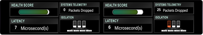
SAS ESP supports real-time analytics using streaming data. These functions of analysis, filtering, and routing by SAS ESP are the main elements that make the whole system work. By performing analysis at the edge, the system can respond very quickly, within milliseconds. By filtering out unnecessary data, the system dramatically reduces the volume of data traversing the network to the data center, reducing the network load and the data ingest and analysis in the core data center. Figure 1 shows one simple example of analytics processing that ESP can perform at the edge. Using analytics, it can detect when a particular variable exceeds its control limit boundaries.
Figure 1 ESP Processing at the edge
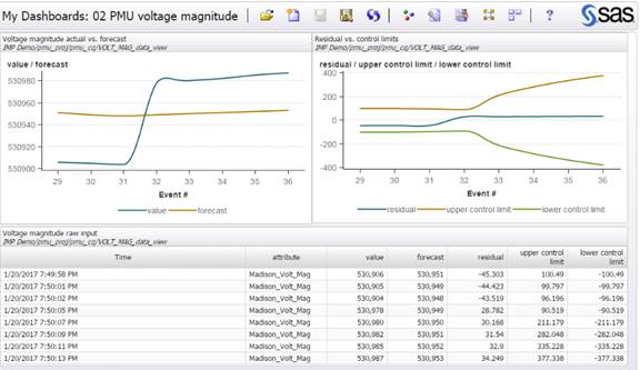
Note that the conditions at the edge of the network are harsh relative to the controlled environment of the data center. Equipment at the edge needs to be specifically designed to survive these conditions. This has an impact on the choices made regarding what services to put where. For example, the cost of using hardened industrial routers capable of running independent applications may be far less than the cost of maintaining a remote facility for less rugged equipment.
The transfer layer includes real-time data pipelines, such as Apache Kafka, that provide a reliable, fault-tolerant, linearly scalable message bus for data in transit to accommodate the flood of messages from the sensors. The data is retained until it is processed and stored in the data center.
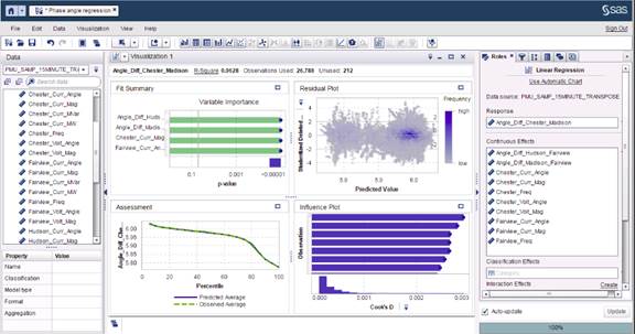
The data center fulfills its traditional role of housing the data and providing the tools to analyze and use the data. The big data analysis needs at the data center are supported by SAS Visual Analytics (VA) and SAS Visual Statistics (VS). Figure 2 is a screen shot from SAS VS illustrating a linear regression model that estimates the phase angle at a point on the power grid. You can use data from substations that have sensors to estimate values in other locations.
Figure 2 SAS Visual Statistics Linear Regression Modeling
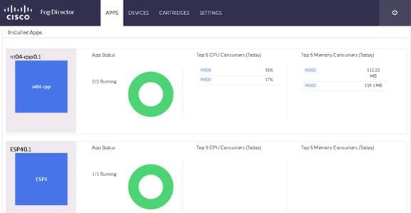
An important function in the data center is the development of models that can be used by the edge systems to analyze the data at the edge. The capability to learn from the deep analysis in the data center and then roll out improved analytical models at the edge provides a continuous feedback loop. Support for a transparent workflow between model development and model deployment is an important differentiator of edge-to-enterprise analytics. For example, Figure 3 shows a screen shot of the Cisco Fog Director application in which the application manages the SAS ESP instances at the edge.
Figure 3 Cisco Fog Director Managing SAS ESP on Edge Routers
With SAS ESP also present in the data center, organizations can develop pattern-detection capabilities across multiple streams of data. Organizations also can develop real-time control center–type dashboards based on the data streaming from various edge locations. For example, Figure 4 shows the number of signals emerging from the various substations in a utilities scenario.
Figure 4 SAS ESP Aggregate Views in the Data Center

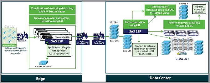
As shown in Figure 5, the Cisco and SAS Edge-to-Enterprise IoT Analytics architecture uses Cisco infrastructure and software technologies to connect to IoT devices at the edge, route data traffic, and run SAS software at both the edge and the core data center. The SAS software at the edge filters data, applies models, and issues alerts.
SAS integrates streaming data with analytics and visualization processes to get more value from the IoT. Whether the data is at the edge, in motion, or at rest, SAS technology helps organizations use it to make decisions quickly, while reducing data movement and storage costs.
Filtered (or relevant) IoT data is routed to the data center by Kafka: a secure, highly available, distributed, message broker.
In the data center, data is stored using Hadoop-based big data technologies on Cisco servers. The data is analyzed both in real time using SAS ESP and in Hadoop for historical analysis. The real-time analysis and model development uses SAS software, including SAS ESP, SAS VA, SAS VS, and SAS LASR Analytics Server.
Figure 5 Cisco and SAS Edge-to-Enterprise IoT Analytics Platform Reference Architecture
The following sections discuss the details of the edge and data center components.
Edge Components
The reference architecture includes the edge components discussed in this section.
Cisco Unified Computing System
At the edge, Cisco UCS Rack mount servers or Cisco UCS Mini is recommended.
Cisco UCS C-Series Rack Servers deliver unified computing in an industry-standard form factor to reduce TCO and increase agility. Each server addresses varying workload challenges through a balance of processing, memory, I/O, and internal storage resources.
Cisco UCS Mini is optimized for branch and remote offices, point-of-sale locations, and smaller IT environments. It is the ideal solution for customers who need fewer servers but still want the comprehensive management capabilities provided by Cisco UCS Manager. Cisco UCS Mini delivers servers, storage, and 10-Gigabit networking in an easy-to-deploy, compact form factor.
The reference architecture presented in this document uses a Cisco UCS C220 M4 Rack server, a 1-rack-unit (1RU) server, to deploy Cisco Fog Director and also serves as an edge network server to address additional reporting and analysis requirements.
Cisco IR829G Industrial Integrated Services (IR829)
The Cisco IR829G Industrial Integrated Services Routers is a ruggedized integrated services router designed for deployment in harsh industrial environments. The Cisco 829 Industrial ISR has a compact form factor, an integrated 9 to 32V DC power input, and multimode third-generation (3G) and fourth-generation (4G) Long-Term Evolution (LTE) wireless WAN and WLAN connections. It can rapidly deploy a wide variety of IoT solutions, including fleet management, mass transit, and remote asset monitoring applications.
Cisco IOx software, an open, extensible environment for hosting applications at the network edge, and SAS ESP software are installed on the Cisco 829 Industrial ISR.
Cisco Fog Director
Cisco Fog Director manages the Cisco 829 Industrial ISR. It provides the capability to manage large-scale production deployments of edge applications that support Cisco IOx, and it controls the IOx application lifecycle, from initial deployment through ongoing change management and application retirement.
Cisco Fog Director employs a visual web interface or can be integrated with existing management systems through an API. Cisco Fog Director supports both application-centric and network-centric infrastructure views to optimize productivity.
Cisco Fog Director is used to deploy and manage the application lifecycle of SAS ESP on the edge Cisco 829 Industrial ISR as a containerized application.
SAS Event Stream Processing
SAS ESP analyzes and acts on events in real time as they occur. SAS ESP is highly embeddable, making it well suited for embedding inside SFF edge devices such as IoT gateways. It is deployed both at the edge and in the core data center. It provides a real-time, low-latency, high-throughput event processing solution. It supports a variety of functions, including machine-learning algorithms (such as neutral networks, gradient boosting, and decision trees), text analysis to categorize text and extract entities, sentiment analysis, advanced pattern matching, in-stream joins, data quality, and much more.
Cisco 3000 Series Industrial Security Appliance (ISA)
Simplify compliance and protect Internet of Things (IoT) Networks from Attacks, Industrial networks have advanced threat protection needs, requiring a ruggedized solution that helps to ensure safe, reliable service delivery. Cisco offers a broad portfolio of solutions for industrial control networks. These include the Industrial Security Appliance 3000 for the most demanding Industrial Control System (ICS) environments. Cisco ruggedized 3000 appliance currently provides the industry's widest range of OT specific access control, threat detection, and application visibility for the harshest and most demanding of environments (with the ability to work in harsh environments, with a temperature range of -40° to 60°C) and is hardened for vibration, shock, surge, and electrical noise immunity. It offers four high-performance Ethernet data links in a DIN rail or rack-mount form factor. The Industrial Security Appliance 3000 extends the network as a sensor and enforcer to IoT environments.
Cisco FirePOWER
The Cisco FirePOWER next-generation firewall (NGFW) is the industry’s first fully integrated, threat-focused next-gen firewall with unified management. It uniquely provides advanced threat protection before, during and after attacks while providing better security, faster speeds and a smaller footprint. The 4100 Series’ 1-rack-unit size is ideal at the Internet edge and in high-performance environments.
Data Center Components
The reference architecture encompasses the components described in this section running on Cisco Unified Computing System™ (Cisco UCS) servers.
Cisco Unified Computing System
As stated earlier, Cisco UCS C-Series Rack Servers and S-Series Storage Servers are industry-leading 2-socket servers designed for both performance and expandability over a wide range of computing and storage-intensive infrastructure workloads. The Cisco UCS C240 Rack Server is an SFF server. It comes with 24 drives and supports a wide range of computing, I/O, and storage demands. The server uses dual Intel Xeon processor E5-2600 v4 series CPUs and supports up to 1.5 TB of main memory and a range of HDD and SSD drive options. This server can be used with the Cisco UCS VIC 1227 or 1387 to provide 10- or 40-Gbps network connectivity.
Kafka
Kafka is an open-source, distributed messaging system that provides fast, highly scalable, and durable messaging through a publish-subscribe model. SAS ESP uses Kafka to handle data pipelines for high-speed filtering and pattern matching. Kafka is co-located in the data center core and deployed on Cisco UCS C240 M4 servers.
SAS Event Stream Processing
SAS ESP provides real-time event stream processing in the data center, capturing data arriving continuously from devices and applications, analyzing it, and acting on new information as it arrives. SAS ESP analyzes millions of events per second, detecting patterns of interest as they occur. It issues alerts and notifications and streams live information to operation dashboards.
SAS ESP in the data center includes a visual model-development environment and a visualization component for building dashboards using streaming data.
SAS Visual Analytics
SAS VA enables organizations to gain insight from all the data, no matter the amount of data, with no need to sample or create subsets of the data. It is implemented as an integrated suite of web applications that offer intuitive, drag-and-drop interactions, rapid, highly visual responses, and role-based access to functions.
SAS Visual Statistics
SAS VS enables organizations to derive predicted values from the predictive models. These new variables contain the prediction information for the models and can be used in other visualizations. Deployed on Cisco UCS C240 servers, SAS VS is fully integrated into SAS VA.
SAS Analytics for IoT Bundle
The SAS ESP, VA, and VS components are encapsulated in a bundle, SAS Analytics for IoT, to provide an industry-independent foundational platform for IoT analytics.
SAS LASR Analytics Server
SAS® LASR Analytic Server is an analytic platform applying analytics to big data. The server provides speedy, secure, multi-user access to in-memory data in a distributed computing environment.
Hadoop
Apache Hadoop is an open-source initiative focused on the big data challenge and a leading solution for enterprise big data implementations. Hadoop provides the software library needed to store, process, and analyze incredibly large amounts of both structured and unstructured data. Hadoop is designed for high availability and linear scaling. In this solution we use Cloudera Enterprise, explained in detail later.
Reference Architecture
The reference architecture includes the components shown in Figure 6 and listed in Table 1.
Figure 6 Reference Architecture
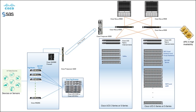
Table 1 Reference Architecture Configuration Details
|
|
Component |
Configuration |
| Edge
|
Cisco IR829G Industrial Integrated Services Routers |
2 cores (1.25 GHz dual core CPU, 2 GB DDR3, 8GB eMMC storage, 4x10/100/1000 Mbps) · 2 cores (1.25-GHz dual-core CPU, 2-GB DDR3, 8-GB embedded multimedia card [eMMC] storage, and 4 x 10/100/1000 Mbps) · IOx : 1.2.0 · Guest OS: Ubuntu 14.04.01/03 · Cisco IOS® Software Release 15M&T · SAS ESP Client: 4.2.0 |
| SAS ESP Client |
Container Application running on IR829G Guest O/S |
|
| Firewall |
In-bound (to IR829): Cisco ISA 3000 Out-bound (from IR829 and Cisco Fog Director): Cisco FirePOWER 4100 series |
|
| Cisco Fog Director |
Cisco UCS C220 M4 servers with: · 2 Intel Xeon processor E5-2680 v4 CPUs (14 cores on each CPU) · 256 GB of memory · Cisco 12-Gbps SAS Modular RAID Controller with 2-GB flash-based write cache (FBWC) · 8 x 1.2TB 10k-rpm HDD · Cisco UCS VIC 1227 (with 2 x 10 Gigabit Ethernet) · Version: 1.2.0 |
|
| Data Pipeline (Transfer) |
Kafka nodes
|
Four Cisco UCS C240 M4 servers each with: · 2 Intel Xeon processor E5-2680 v4 CPUs (14 cores on each CPU) · 256 GB of memory · Cisco 12-Gbps SAS Modular RAID Controller with 2-GB flash-based write cache (FBWC) · 24 x 1.8-TB 10k-rpm HDD · 2 x 240-GB 6-Gbps 2.5-inch enterprise value SATA SSD drives for boot · Cisco UCS VIC 1387 (with 2 x 40 Gigabit Ethernet QSFP ports) Alternate Reference Architecture with Cisco S-Series Server: · Cisco UCS S3260 M4 servers each with two nodes, each node with: · 2 Intel Xeon processor E5-2680 v4 CPUs (14 cores on each CPU) · 256 GB of memory · Cisco 12-Gbps SAS Modular RAID Controller with 2-GB flash-based write cache (FBWC) · 28 x 4TB 10k HDD · 2 x 480-GB 6-Gbps 2.5-inch enterprise value SATA SSD drives for boot · Cisco UCS SIOC (with 2 x 40 Gigabit Ethernet QSFP ports) |
|
|
Firewall |
Inbound to Kafka: Cisco FirePOWER 9300 series |
| Data Center Core |
Connectivity |
Cisco ACI spine-leaf architecture consisting of: · Two Cisco Nexus 9508 Spine switches · Two Cisco Nexus 9332 Leaf switches · One Cisco Nexus 9372 Leaf switch · Three Cisco APIC M2 appliances · Four Cisco UCS 6332 Fabric Interconnects |
| Hadoop |
Management Nodes: 3 nodes Data Nodes: 16 nodes All nodes are Cisco UCS C240 M4 servers each with: · 2 Intel Xeon processor E5-2690 v4 CPUs (14 cores on each CPU) · 512 GB of memory · Cisco 12-Gbps Modular SAS HBA · 8 x 1.6-TB SSD · 2 x 240-GB 6-Gbps 2.5-inch enterprise value SATA SSD drives for boot · Cisco UCS VIC 1387 (with 2 x 40 Gigabit Ethernet QSFP ports) Alternate Reference Architecture with Cisco S-Series Server: · Cisco UCS S3260 M4 storage servers each with two nodes, each node with: · 2 Intel Xeon processor E5-2690 v4 CPUs (14 cores on each CPU) · 512 GB of memory · Cisco 12-Gbps SAS Modular RAID Controller with 2-GB flash-based write cache (FBWC) · 8 x 1.6-TB SSD · 12 x 4TB 10k HDD · 2 x 480-GB 6-Gbps 2.5-inch enterprise value SATA SSD drives for boot · Cisco UCS SIOC (with 2 x 40 Gigabit Ethernet QSFP ports) |
|
| SAS LASR |
Collocated with all Data Nodes |
|
| SAS VA/VS (Visual Analytics and Visual Statistics) |
3 Cisco UCS C240 M4 servers each with: · 2 Intel Xeon processor E5-2690 v4 CPUs (14 cores on each CPU) · 512 GB of memory · Cisco 12-Gbps Modular SAS HBA · 8 x 1.6-TB SSD · 2 x 240-GB 6-Gbps 2.5-inch enterprise value SATA SSD drives for boot · Cisco UCS VIC 1387 (with 2 x 40 Gigabit Ethernet QSFP ports) |
|
|
|
SAS ESP Server
|
2 Cisco UCS C240 M4 servers each with: · 2 Intel Xeon processor E5-2690 v4 CPUs (14 cores on each CPU) · 512 GB of memory · Cisco 12-Gbps Modular SAS HBA · 8 x 1.6-TB SSD · 2 x 240-GB 6-Gbps 2.5-inch enterprise value SATA SSD drives for boot · Cisco UCS VIC 1387 (with 2 x 40 Gigabit Ethernet QSFP ports) |
Sizing Guidelines
Kafka
Table 2 shows the scaling and sizing guidelines for Kafka storage, for various drives, and replication factors.
Time taken for filling one server = ~((Total Storage)/Network Bandwidth)/3600)
Table 2 Scaling and Sizing Guidelines
| Network Bandwidth |
Server Type |
Total Usable Storage |
Time to Fill One server |
Total Servers |
Total Servers |
|
|
|
|
|
(1 way replicated data) (Full network utilization) |
(3 way replicated data) (Full network utilization) |
| 10 Gbps (1.25 GBps) |
C240 M4 (SFF) with 1.8 TB drives |
~40800 GB |
~9 hours |
~3 servers for storing 1 day of data |
~9 servers for storing 1 day of data |
| 40 Gbps (5 GBps) |
C240 M4 (SFF) with 1.8 TB drives |
~40800 GB |
~2.3 hours |
~10 servers for storing 1 day of data |
~30 servers for storing 1 day of data ( |
| 10 Gbps (1.25 GBps) |
C240 M4 (LFF) with 6 TB drives |
~72000 GB |
~16 hours |
~2 servers for storing 1 day of data |
~6 servers for storing 1 day of data |
| 40 Gbps |
C240 M4 (LFF) with 6 TB drives |
~72000 GB |
~4 hours |
~ 6 servers for storing 1 day of data |
~18 servers for storing 1 day of data |
Cisco UCS Integrated Infrastructure for Big Data and Analytics
The Cisco UCS Integrated Infrastructure for Big Data and Analytics solution is based on Cisco UCS Integrated Infrastructure for Big Data and Analytics, a highly scalable architecture designed to meet a variety of scale-out application demands with seamless data integration and management integration capabilities built using the following components:
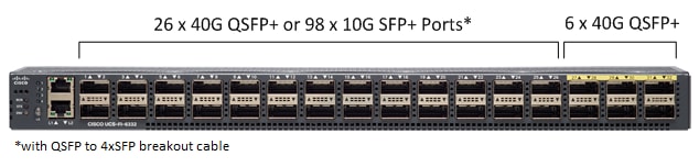
Cisco UCS 6300 Series Fabric Interconnects
Cisco UCS 6300 Series Fabric Interconnects provide high-bandwidth, low-latency, lossless 10 and 40 Gigabit Ethernet, Fiber Channel over Ethernet (FCoE), and Fiber Channel functions with management capabilities for the system. All servers attached to Fabric interconnects become part of a single, highly-available management domain.
Deployed in redundant pairs, Cisco UCS Fabric Interconnects offer the full active-active redundancy, performance and exceptional scalability needed to support the large number of nodes that are typical in clusters serving edge-to-enterprise analytic applications. See Figure 7.
Figure 7 Cisco UCS 6332 32-Port Fabric Interconnect
Cisco UCS C-Series Rack Mount Servers
Cisco UCS C-Series Rack Servers deliver unified computing in an industry-standard form factor to reduce total cost of ownership and increase agility. Each product addresses varying workload challenges through a balance of processing, memory, I/O, and internal storage resources.
Cisco UCS unifies computing, networking, management, virtualization, and storage access into a single integrated architecture that can enable edge-to-enterprise server visibility, management, and control in both bare-metal and virtualized environments. With Cisco UCS-managed deployment, UCS C-Series servers take advantage of standards-based unified computing innovations to significantly reduce customers' TCO and increase business agility.
The Cisco UCS C220 M4 and C240 M4 Rack Servers provide:
· Dual Intel Xeon E5-2600 v4 processors for improved performance
· Next-generation double-data-rate 4 (DDR4) memory, 12-Gbps SAS throughput, and NVMe PCIe SSD support
· Innovative Cisco UCS Virtual Interface Card (VIC) support in PCIe or modular LAN-on-motherboard (mLOM) form factor
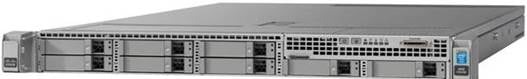
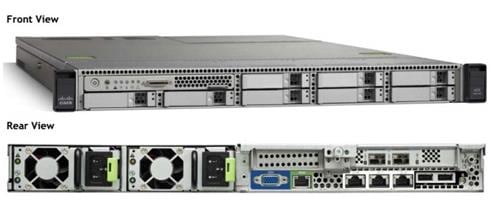
Cisco UCS C220 M4 Rack Server
The Cisco UCS C220 M4 Rack Server is a versatile, high-density, general-purpose enterprise infrastructure and application server (Figure 8). It delivers world-record performance for a wide range of enterprise workloads.
Table 3 Cisco UCS C220 M4 Rack Server Specifications At-a-Glance
| Item |
Specification |
| Chassis |
One rack-unit (1-RU) server |
| Processor |
Either one or two Intel® Xeon® processor E5-2600 v4 product family CPUs |
| Memory |
24 double-data-rate 4 (DDR4) dual in-line memory (DIMMs) of up to 2400 MHz speeds. Up to 1.5 TB of main memory |
| PCIe slots |
Six PCI Express (PCIe) Generation 3 slots (four full-height and full-length; four NCSI-capable and VIC-ready; two GPU-ready) |
| Hard drives |
8 small-form factor (SFF) drives or 4 large form-factor (LFF) drives, plus two optional internal SATA boot drives, and NVMe drive support |
Figure 8 Cisco UCS C220 M4 Rack Server
Cisco UCS C240 M4 Rack Server
Figure 9 shows the Cisco UCS C240 Rack Server
Figure 9 Cisco UCS C240 M4 Rack Server
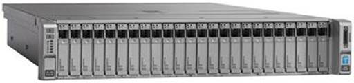
Table 4 Cisco UCS C240 M4 Rack Server Specifications At-a-Glance
| Item |
Specification |
| Chassis |
Two rack-unit (2-RU) server |
| Processor |
Either one or two Intel® Xeon® processor E5-2600 v4 product family CPUs |
| Memory |
24 double-data-rate 4 (DDR4) dual in-line memory (DIMMs) of up to 2400 MHz speeds. Up to 1.5 TB of main memory. |
| PCIe slots |
Six PCI Express (PCIe) Generation 3 slots (four full-height and full-length; four NCSI-capable and VIC-ready; two GPU-ready) |
| Hard drives |
24 small-form factor (SFF) drives or 12 large form-factor (LFF) drives, plus two optional internal SATA boot drives, and NVMe drive support |
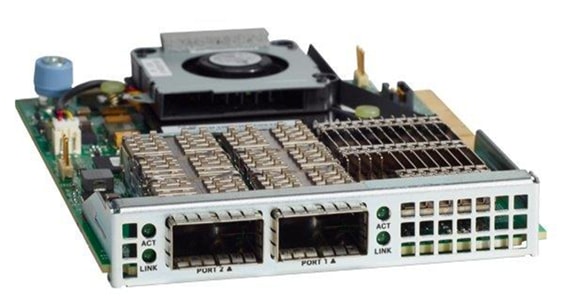
Cisco UCS Virtual Interface Card 1387
Cisco UCS Virtual Interface Cards (VICs) are unique to Cisco. Cisco UCS Virtual Interface Cards incorporate next-generation converged network adapter (CNA) technology from Cisco. Optimized for virtualized networking, these cards deliver high performance and bandwidth utilization, and support up to 256 virtual devices.
The Cisco UCS Virtual Interface Card 1387 offers dual-port, Enhanced Quad, Small Form-Factor Pluggable (QSFP) 40 Gigabit Ethernet and Fiber Channel over Ethernet (FCoE), in a modular-LAN-on-motherboard (mLOM) form factor. The mLOM slot can be used to install a Cisco VIC without consuming a PCIe slot providing greater I/O expandability. See Figure 10.
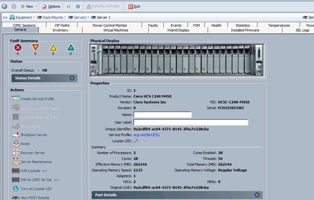
Cisco UCS Manager
Cisco UCS Manager resides within the Cisco UCS 6300-series Fabric Interconnects. It makes the system self-aware and self-integrating, managing all of the system components as a single logical entity. Cisco UCS Manager can be accessed through an intuitive graphical user interface (GUI), a command-line interface (CLI) or an XML application-programming interface (API). Cisco UCS Manager uses service profiles to define the personality, configuration and connectivity of all resources within Cisco UCS, radically simplifying provisioning of resources so that the process takes minutes instead of days.
Cisco UCS Manager enables rapid and consistent server configuration using service profiles, automating ongoing system maintenance activities such as firmware updates across the entire cluster as a single operation. Cisco UCS Manager also offers advanced monitoring with options to raise alarms and send notifications about the health of the entire cluster. The advanced features of the Cisco UCS Manager allow IT departments to shift their focus from constant maintenance to strategic business initiatives. See Figure 11.
Cisco 829 Industrial Integrated Services Router
Cisco® 829 Industrial Integrated Services Routers are ruggedized integrated services routers designed for deployment in harsh industrial environments. The Cisco IR829G Industrial Integrated Services Routers have a compact form factor, integrated 9-32 VDC power input, and multimode 3G and 4G LTE wireless WAN and IEEE 802.11a/b/g/n WLAN connections.
With the Cisco IR829G, you can rapidly deploy a wide variety of Internet of Things (IoT) solutions, including fleet management, mass transit, and remote asset monitoring. The Cisco IR829G routers are designed to withstand hostile environments including shock, vibration, dust, humidity, and water sprayed from all directions, as well as a wide temperature range (-40°C to +60°C and type-tested at +85°C for 16 hours).
The Cisco IR829G brings together enterprise-grade wireline-like services such as quality of service (QoS), Cisco advanced VPN technologies (DMVPN, Flex VPN and GETVPN) and multi-VRF for WAN, highly secure data, voice, and video communications and Cisco IOx, an open, extensible environment for hosting applications at the network edge.
Cisco Fog Director
Cisco Fog Director delivers the capability to manage large-scale production deployments of IOx-enabled fog applications including controlling the IOx application lifecycle from initial deployment through ongoing change management and application retirement. It can be operated from a visual web environment or integrated with existing management systems through APIs. Cisco Fog Director supports both application centric and network infrastructure centric views to optimize productivity.
Cisco Fog Director improves operational effectiveness with a single point of control for applications and associated network infrastructure at production scale. It increases line of business agility with systematic change management of IOx-enabled fog applications, and enhances returns on application development investment through acceleration of deployment and scalable application lifecycle management.
Cisco Fog Computing Architecture
IOx is Cisco’s implementation of Fog Computing. IOx enables hosting of applications and services developed by Cisco, its partners and third party developers in network edge devices in a seamless fashion across diverse and disparate hardware platforms.
IOx provides a seamless application enablement framework and compute platform across various devices operating at the network edge with the ability to host applications and services, connecting them securely and reliably to applications in the cloud. The term Application enablement covers all life cycle aspects of applications including development, distribution, deployment, hosting, monitoring and management.
For the following discussion please refer to Figure 12.
Figure 12 IOx High Level Architecture
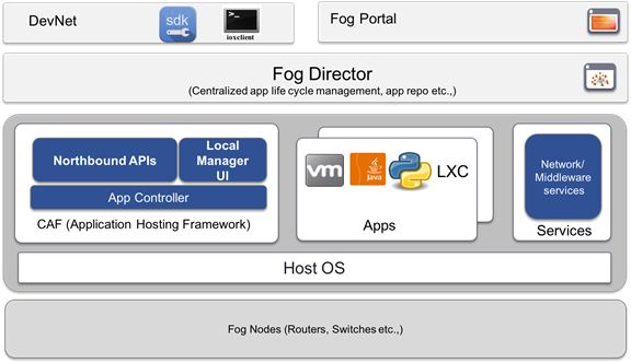
Fog Nodes
These are the devices that provides compute and runtime resources for applications.
CAF
Cisco application hosting framework (CAF) is responsible for orchestrating and managing applications on Fog nodes. At a high level, it provides:
· Application lifecycle management (Install, Start, Stop, Monitor, Uninstall, Upgrade)
· Resource provisioning and management (CPU, memory, network, storage etc.)
· Application monitoring and metrics collection
· Provides mechanisms for troubleshooting and debugging (Access to application and platform logs, access to application console etc.)
IOx Middleware Services
IOx middleware services provide high-level abstractions and APIs to accelerate the development of IOx applications.
Apps
Apps embody the logic that has to run on a Fog node. IOx supports different application types that cater to wide variety of use cases.
Local Manager
Local manager is the embedded web UI supported by CAF geared towards application lifecycle management for a single node.
Fog Director
Fog Director provides centralized management services to manage all life cycle aspects of applications and services on thousands of fog nodes enabling operations at scale.
Fog director also provides uniform north bound RESTful APIs which can be used by client programs to integrate application management into their workflows. The Fog Director RESTful API documentation are available here.
Fog director usage and reference guide is available here.
IOx SDK
The IOx SDK is a set of tools and software packages used by 3rd party developers to build applications that can be hosted by CAF on Cisco's IOx enabled platforms.
ioxclient
ioxclient is a cross platform command line utility primarily meant for assisting application development for Cisco's IOx platforms. It aims to increase developer productivity by providing easy to use CLIs for all application lifecycle tasks.
Fog Portal
Fog portal is the primary interface for developers to interact with Cisco IOx ecosystem. A single stop portal that provides all the developer resources for the developer to develop, test their application and make them available for deployment via Fog director.
Cisco Application Centric Infrastructure (ACI) Overview
Cisco ACI provides the network the ability to deploy and respond to the needs of applications, both in the data center and in the cloud. The network must be able to deliver the right levels of connectivity, security, compliance, firewalls, and load balancing, and it must be able to do this dynamically and on-demand.
This is accomplished through centrally defined policies and application profiles.
The profiles are managed by the Application Policy Infrastructure Controller [APIC] and distributed to switches, like the Cisco Nexus 9000 Series. Cisco Nexus 9000 Series Switches and the Cisco Application Policy Infrastructure Controller (APIC) are the building blocks for Cisco ACI.
Cisco ACI is software-defined networking (SDN) plus a whole lot more. Most SDN models stop at the network. Cisco ACI extends the promise of SDN-namely agility and automation-to the applications themselves. Through a policy-driven model, the network can cater to the needs of each application, with security, network segmentation, and automation at scale. And it can do so across physical and virtual environments, with a single pane of management.
The Cisco ACI fabric supports more than 64,000 dedicated tenant networks. A single fabric can support more than one million IPv4/IPv6 endpoints, more than 64,000 tenants, and more than 200,000 10G ports. The Cisco ACI fabric enables any service (physical or virtual) anywhere, with no need for additional software or hardware gateways, to connect between the physical and virtual services, and normalizes encapsulations for Virtual Extensible Local Area Network (VXLAN) / VLAN / Network Virtualization using Generic Routing Encapsulation (NVGRE).
The Cisco ACI fabric decouples the endpoint identity and associated policy from the underlying forwarding graph. It provides a distributed Layer 3 gateway that ensures optimal Layer 3 and Layer 2 forwarding. The fabric supports standard bridging and routing semantics without standard location constraints (any IP address anywhere), and removes flooding requirements for the IP control plane Address Resolution Protocol (ARP) / Generic Attribute Registration Protocol (GARP). All traffic within the fabric is encapsulated within VXLAN.
Architectural Benefits of Using Fabric Interconnect with Cisco ACI
The Cisco ACI fabric consists of discrete components that operate as routers and switches, but is provisioned and monitored as a single entity. The operation is like a single switch and router that provides advanced traffic optimization, security, and telemetry functions, stitching together virtual and physical workloads.
Cisco Application Centric Infrastructure (ACI) and Cisco Unified Computing System (Cisco UCS), working together, can cost-effectively scale capacity, and deliver exceptional performance for the growing demands of big data processing, analytics, and storage workflows. For larger clusters and mixed workloads, Cisco ACI uses intelligent, policy-based flowlet switching and packet prioritization to deliver:
· Centralized Management for the entire Network
· Dynamic load balancing
· Dynamic Packet Prioritization
· Multi-Tenant and Mixed Workload Support
· Deep Telemetry
Centralized Management for the Entire Network
Cisco ACI treats the network as a single entity rather than a collection of switches. It uses a central controller to implicitly automate common practices such as Cisco ACI fabric startup, upgrades, and individual element configuration. The Cisco Application Policy Infrastructure Controller (Cisco APIC) is the unifying point of automation and management for the Cisco Application Centric Infrastructure (ACI) fabric. This architectural approach dramatically increases the operational efficiency of networks, by reducing the time and effort needed to make modifications to the network and, also, for root cause analysis and issue resolution
Dynamic Load Balancing
Cisco's Application Centric Infrastructure is not only aware of the congestion points but is able to make dynamic decisions on how the traffic is switched/routed. This could be new flows that are about to start or existing long flows which could benefit from moving to a less congested route. Dynamic load balancing takes care of these decisions at run time automatically and helps utilize the links optimally - both the healthy and the congested links. This is useful in both congested link scenarios and scenarios where there are link failures. Even when there is no congestion this will maintain close to optimal distribution of traffic across the spines.
Dynamic Packet Prioritization (DPP) prioritizes short flows higher than long flows; a short flow is less than approximately 15 packets. Short flows are more sensitive to latency than long ones. Small and urgent data workloads, such as database queries, may suffer processing latency delays because larger data sets are being sent across the fabric ahead of them. This approach presents a challenge for instances in which database queries require near-real-time results.
Dynamic Packet Prioritization can improve overall application performance. Together these technologies enable performance enhancements to applications, including Big Data workloads.
Multi-Tenant and Mixed Workload Support
Cisco ACI is built to incorporate secure multi-tenancy capabilities. The fabric enables customers to host multiple concurrent Big Data clusters on a shared infrastructure. Cisco ACI provides the capability to enforce proper isolation and SLA's for workloads of different tenants. These benefits extend beyond multiple Big Data workloads - Cisco ACI allows the same cluster to run a variety of different application workloads, not just Big Data, with the right level of security and SLA for each workload.
Deep Telemetry of Tenant and Application Network
One of the core design principles behind Cisco ACI is to provide complete visibility into the infrastructure - physical and virtual. Cisco APIC is designed to provide application and tenant health at a system level by using real-time metrics, latency details, atomic counters, and detailed resource consumption statistics
If your application is experiencing performance issues, you can drill down easily into the lowest possible granularity - be it at a switch level, line card level, or port level.
The holistic approach to correlate virtual and physical and tie that intelligence to an application or tenant level ensures that troubleshooting becomes extremely simple across your infrastructure, through a single pane of glass.
Cisco ACI Building Blocks
Cisco ACI consists of:
· Cisco Nexus 9000 Series Switches
· Centralized policy management and Cisco Application Policy Infrastructure Controller (APIC)
Cisco Nexus 9000 Series Switches
The Cisco Nexus 9000 Series Switches offer both modular (9500 switches) and fixed (9300 switches), 1/10/40/100 Gigabit Ethernet switch configurations designed to operate in one of two modes:
Cisco NX-OS mode for traditional architectures and consistency across the Cisco Nexus portfolio.
Cisco ACI mode to take full advantage of the policy-driven services and infrastructure automation features of ACI.
The ACI-Ready Cisco Nexus 9000 Series provides:
· Accelerated migration to 40G: zero cabling upgrade cost with Cisco QSFP+ BiDi Transceiver Module innovation.
· Switching platform integration: Cisco Nexus 9000 Series enables a highly scalable architecture and is software upgradable to ACI.
· Streamlined application management: drastically reduce application deployment time and get edge-to-enterprise application visibility.
This architecture consists of Cisco Nexus 9500 series switches acting as the spine, and Nexus 9300 series switches as leaves.
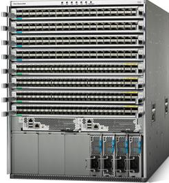
Cisco Nexus 9508 Spine Switch
The Cisco Nexus 9508 Switch offers a comprehensive feature set, high resiliency, and a broad range of 1/10/40 Gigabit Ethernet line cards to meet the most demanding requirements of enterprise, service provider, and cloud data centers. The Cisco Nexus 9508 Switch is an ACI modular spine device enabled by a non-blocking 40 Gigabit Ethernet line card, supervisors, system controllers, and power supplies. See Figure 13.
The Cisco Nexus 9500 platform internally uses a Clos fabric design that interconnects the line cards with rear-mounted fabric modules. The Cisco Nexus 9500 platform supports up to six fabric modules, each of which provides up to 10.24-Tbps line-rate packet forwarding capacity. All fabric cards are directly connected to all line cards. With load balancing across fabric cards, the architecture achieves optimal bandwidth distribution within the chassis.
Figure 13 Cisco Nexus 9508 Switch
ACI Spine Line Card for Cisco Nexus 9508
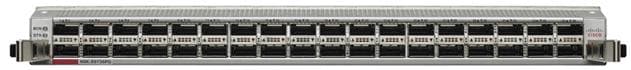
There are multiple spine line cards supported on Cisco Nexus 9508. This architecture uses the N9K-X9736PQ: 40 Gigabit Ethernet ACI Spine Line Card. See Figure 14.
· 36-port 40 Gigabit Ethernet QSFP+ line card
· Non-blocking
· Designed for use in an ACI spine switch role
· Works only in ACI mode
· Cannot mix with non-spine line cards
· Supported in 8-slot chassis
Figure 14 N9K-X973PQ Line Card
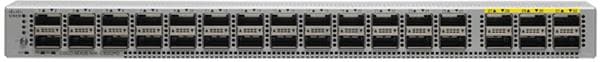
Cisco Nexus 9332 Leaf Switch
The Cisco Nexus 9332PQ switch delivers comprehensive line-rate, layer 2 and layer 3 features in a one-rack-unit (1-RU) form factor. It supports a line rate of 1/40 GE with 2.56 Tbps of bandwidth over 720 million packets / sec (mpps) across 32 fixed 40-Gbps QSFP+ ports. It is ideal for top-of-rack and middle-of-row deployments in both traditional and Cisco Application Centric Infrastructure (ACI)–enabled enterprise, service provider, and cloud environments. See Figure 15.
Figure 15 Cisco Nexus 933PQ Switch
Application Policy Infrastructure Controller (APIC)
The APIC is the unified point of automation, management, monitoring, and programmability for the Cisco Application Centric Infrastructure. The APIC supports the deployment, management, and monitoring of any application anywhere, with a unified operations model for physical and virtual components of the infrastructure. The APIC programmatically automates network provisioning and control that is based on the application requirements and policies. It is the central control engine for the broader cloud network; it simplifies management and allows flexibility in how application networks are defined and automated. It also provides northbound REST APIs. The APIC is a distributed system that is implemented as a cluster of many controller instances. See Figure 16.
Cisco ACI Topology
Cisco ACI topology is spine-leaf architecture. Each leaf is connected to each spine. It uses internal routing protocol; Intermediate System to Intermediate System (IS-IS) to establish IP connectivity throughout the fabric among all the nodes including spine and leaf. To transport tenant traffic across the IP fabric, integrated VxLAN overlay is used. The broadcast ARP traffic coming from the end point or hosts to the leaf are translated to unicast ARP in the fabric.
The forwarding is done as a host based forwarding. In the leaf layer the user information such as username, IP address, locations, policy groups etc., are decoupled from the actual forwarding path and encode them into the fabric VxLAN header and is forwarded to the desired destination.
Each spine has the complete forwarding information about the end hosts that are connected to the fabric and on every leaf have the cached forwarding information. The leaf only needs to know the hosts it needs to talk to. For example, if Server Rack-1 has to send some information to Server Rack-2, when a packet comes in the ingress leaf (LEAF_1) it will encapsulate the information into the VxLAN header and forward that information to LEAF_2. If the LEAF_1 does not have information about the LEAF_2, it uses Spine as a proxy and since Spine has all the complete information about the entire end host connected to the fabric, it will resolve the egress leaf and forward the packet to the destination.
To the outside world, routing protocols can be used to learn outside prefixes or static routing can be used instead. The outside learned routes will be populated into the fabric or to the other leafs with Multiprotocol BGP (M-BGP). In M-BGP topology the spine nodes acts as route reflectors.
The Network topology of ACI is as depicted in Figure 17.
Figure 17 Network Topology Based on Cisco ACI
The Cisco ACI infrastructure incorporates the following components:
· Two Cisco Nexus 9508 Spine Switch
· Cisco ACI Spine Line Card for Nexus 9508
· Cisco Nexus 9332 Leaf Switch for Data Traffic
· Cisco APIC-M2-Cluster with three APIC-M2 appliances
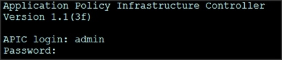
Once the configuration is completed, the APIC will Boot its APIC IOS Image and will ask for the login information. The default username is "admin" and the password is the one that was set during the initial configuration. See Figure 18.

SAS Advanced Analytics
SAS is the market leader in advanced analytics with decades of experience and a broad portfolio of innovative products that help businesses turn data into actionable insight. This design uses advanced tools from SAS Institute for data filtering, analysis and response at the edge of the network and historical analysis, real-time analysis and model development in the data center, including: SAS Event Stream Processing (ESP), SAS Visual Analytics (VA), SAS Visual Statistics (VS), SAS Event Stream Processing Server and LASR Analytics Server.
SAS Event Stream Processing (ESP)
SAS Event Stream Processing analyzes and acts on events as they happen in real-time. Its complex event processing (CEP) platform delivers real-time stream processing and analytics.
SAS Visual Analytics
SAS Visual Analytics enables you to gain insight from all of your data, no matter the size of your data, with no need to subset or sample the data. It is implemented as an integrated suite of web applications that offer intuitive, drag-and-drop interactions, rapid, highly visual responses, and role-based access to functionality.
Deployed on Cisco UCS C240 servers, data is prepared from data sources and loaded in to memory. Analysts interactively explore, analyze, and interpret the data. Report designers create reports and dashboards. Report consumers view reports via a web interface or on their mobile devices.
SAS Visual Statistics
SAS Visual Statistics enables you to derive predicted values from the predictive models. These new variables contain the prediction information for your models and can be used in other visualizations. Deployed on Cisco UCS C240 servers, SAS Visual Statistics is fully integrated into SAS Visual Analytics.
SAS Event Stream Processing (ESP) Server
SAS Event Stream Processing (ESP) Server provides real-time event stream processing in the data center capturing data arriving continuously from devices and applications, analyzing and acting on new information as it arrives. It issues alerts and notifications, and streams live information to operational dashboards.
SAS LASR Analytics Server
SAS® LASR Analytic Server is an analytic platform applying analytics to big data. The server provides speedy, secure, multi-user access to in-memory data in a distributed computing environment. It also handles smaller data sets and supports an alternate, single-machine configuration.
Cloudera Enterprise
Hadoop is a new type of data platform: one place to store unlimited data and access that data with multiple frameworks, all within the same platform. However, all too often, enterprises struggle to turn this new technology into real business value.
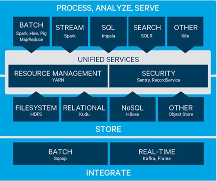
Powered by the world's most popular Hadoop distribution, Cloudera Enterprise (Figure 19) makes Hadoop fast, easy, and secure so you can focus on results, not the technology.
Fast for Business - Cloudera Enterprise enables more insights for more users, all within a single platform. With powerful open source tools and active data optimization designed for Hadoop, you can move from big data to results faster. Key features include:
· Fast Analytic SQL: The lowest latency and best concurrency for BI with Apache Impala
· Native Search: Complete user accessibility built-into the platform with Apache Solr
· Active Data Optimization: Cloudera Navigator Optimizer helps tune data and workloads for peak performance with Hadoop
Easy to Manage - Hadoop is a complex, evolving ecosystem of open source projects. Cloudera Enterprise makes it simple so you can run at scale, across a variety of environments, all while meeting SLAs. Key features include:
· Powerful Cluster Operations: Cloudera Manager is the Hadoop administration tool trusted by the professionals
· Expert Support: Dedicated help and predictive care, just a click away
· Open Source Leadership: Constant open source development and curation, with the most rigorous testing, for trusted innovation
Secure without Compromise - The potential of big data is huge, but not at the expense of security. Cloudera Enterprise achieves compliance with its comprehensive security and governance. Key features include:
· Enterprise Encryption and Key Management: Protect everything with Navigator Encrypt and Navigator Key Trustee
· Uniform Access Policy Enforcement: Uniformly manage and enforce role-based access controls across the entire platform with Apache Sentry and RecordService
· Automated Data Management: Full-stack audit, lineage, discovery, and lifecycle management for Hadoop with Cloudera Navigator
· Secure Operations: Separation of duties to protect production environments and built-in log and query redaction to protect sensitive information
Apache Kafka
Apache Kafka is a distributed publish-subscribe messaging system that is designed to be fast, scalable and durable. Kafka maintains feeds of messages in topics. Producers write data to topics and consumers read from topics. Since Kafka is a distributed system, topics are partitioned and replicated across multiple nodes. Kafka is designed to allow a single cluster to serve as the central data backbone for a large organization. It can be elastically and transparently expanded without downtime. Data streams are partitioned and spread over a cluster of machines to allow data streams larger than the capability of any single machine and to allow clusters of coordinated consumers.
Messages are simply byte arrays and developers can use them to store any object in any format, with String, JSON, and Avro the most common. It is possible to attach a key to each message, in which case the producer guarantees that all messages with the same key will arrive to the same partition.
Messages are persisted on disk and replicated within the cluster to prevent data loss. Each broker can handle terabytes of messages without performance impact. When consuming from a topic, it is possible to configure a consumer group with multiple consumers. Each consumer in a consumer group will read messages from a unique subset of partitions in each topic they subscribe to, so each message is delivered to one consumer in the group, and all messages with the same key arrive at the same consumer.
What makes Kafka unique is that Kafka treats each topic partition as a log (an ordered set of messages). Each message in a partition is assigned a unique offset. Kafka does not attempt to track, which messages were read by each consumer and only retain unread messages; rather, Kafka retains all messages for a set amount of time, and consumers are responsible to track their location in each log. Consequently, Kafka can support a large number of consumers and retain large amounts of data with very little overhead.
Kafka allows clients to choose synchronous or asynchronous replications. In the former case message is acknowledged only after it reaches multiple replicas, in the latter case a message to be published is acknowledged as soon as it reaches one replica. The purpose of adding replication in Kafka is for stronger durability and higher availability. Details on how to configure the replicas are captured later in this document.
Please refer to http://www.cloudera.com/products.html for more details.
Requirements
This CVD describes the architecture and deployment procedures to create an edge-to-enterprise analytics system using Cisco servers, switches and routers, SAS analytics software and the Cloudera distribution for big data systems.
The cluster configuration consists of the following:
· 28 Cisco UCS C240 M4 Rack Servers fulfilling a variety of roles,
- 16 x HDFS data nodes collocated with SAS LASR
- 3 x HDFS management nodes
- 3 x SAS VA/VS nodes
- 2 x SAS ESP server nodes
- 4 x Kafka nodes
· One Cisco UCS C220 M4 Rack Server for Cisco Fog Director, used to manage the fog nodes,
· Four Cisco UCS 6332 Fabric Interconnects
· Two Cisco Nexus 9508 spine switches
· Two Cisco Nexus 9332 leaf switches
· One Cisco Nexus 9372PX leaf switch
· Three Cisco APIC M2 appliances
· Four Cisco IR829G Industrial Integrated Services Routers
· Cisco R42610 standard racks
· Cisco Vertical Power distribution units (PDUs) (Country Specific)
Software Distributions and Versions
The required software distribution versions are listed below.
Cloudera Enterprise 5.7
Cloudera Enterprise version used is 5.7. For more information visit https://www.cloudera.com/documentation/enterprise/release-notes/topics/cdh_vd_cdh5_maven_repo_58x.html - concept_s1z_m5f_x5
SAS
· SAS LASR: 3.4
· SAS Event Stream Processing Client : 4.2
· SAS Event Stream Processing Server: 4.2
· SAS Visual Analytics (VA), SAS Visual Analytics (VS): 7.3
![]() Note: On 9.4 platform (Linux for x64) for Distributed processing.
Note: On 9.4 platform (Linux for x64) for Distributed processing.
For more information visit: www.sas.com
Red Hat Enterprise Linux (RHEL)
The operating system implemented is Red Hat Enterprise Linux 7.2. For more information visit http://www.redhat.com.
Software Versions
The software versions tested and validated in this document are shown in Table 5.
|
|
Component |
Version or Release |
| Compute |
Cisco UCS C240-M4 |
C240M4.2.0.13d |
| Cisco UCS C220-M4 |
C220M4.2.0.13d |
|
| Network |
Cisco UCS 6332 |
UCS 3.1(2b) |
| Cisco UCS VIC1387 Firmware |
4.1(2d) |
|
| Cisco UCS VIC1387 Driver |
2.3.0.31 |
|
| Storage |
LSI SAS 3108 |
24.12.1-0049 |
| LSI MegaRAID SAS Driver |
06.810.10.00 |
|
| Software |
Red Hat Enterprise Linux Server |
7.2 (x86_64) |
| Cisco UCS Manager |
3.1(2b) |
|
| CDH |
5.8.0 |
|
| SAS LASR |
3.4 |
|
| SAS Event Stream Processing (ESP) |
4.2 |
|
| SAS Event Stream Processing Server |
4.2 |
|
| SAS Visual Analytics / Visual Statistics (VA/VS) |
7.3 |
|
| Cisco Fog Director |
1.2.0 |
|
| Cisco IR829G router |
IOS |
15.6.3M |
| Fog node |
1.2.4.2 |
|
| IOx local manager |
1.2.0.0 |
![]() Note: The latest drivers can be downloaded from this link: https://software.cisco.com/download/release.html?mdfid=283862063&release=2.0(13)&relind=AVAILABLE&flowid=25886&softwareid=283853158&rellifecycle=&reltype=latest
Note: The latest drivers can be downloaded from this link: https://software.cisco.com/download/release.html?mdfid=283862063&release=2.0(13)&relind=AVAILABLE&flowid=25886&softwareid=283853158&rellifecycle=&reltype=latest
![]() Note: The latest supported RAID controller driver is already included with the RHEL 7.2 operating system.
Note: The latest supported RAID controller driver is already included with the RHEL 7.2 operating system.
System Architecture
The system architecture includes Cisco UCS C240 M4 servers, based on Cisco UCS Integrated Infrastructure for Big Data and Analytics with two domains. Each domain can support up to 30 servers under a pair of Fabric Interconnects depending on the number of uplink ports, interconnected through ACI Fabric. For this design, we are using eight uplink ports leaving 24 ports for the servers.
The ACI fabric consists of three major components: the Application Policy Infrastructure Controller (APIC), spine switches and leaf switches. These three components handle both the application of network policy and the delivery of packets.
The system architecture consists of two domains (two pairs of FIs) connecting to ACI having:
· Two Cisco Nexus 9508 switches acting as a spine
· Two Cisco Nexus 9332 as the leaf switches
· Three APIC-M2 as APIC appliances
· One Cisco Nexus 9372 leaf switch used to connect the Cisco IR829G routers to the network
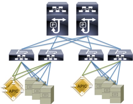
Figure 20 shows the overall system architecture of the solution.
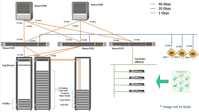
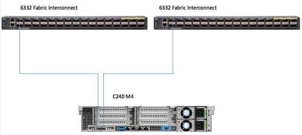
Figure 21 shows the connectivity between the leaf switches and fabric interconnects.
Figure 21 Leaf/Fabric Interconnect
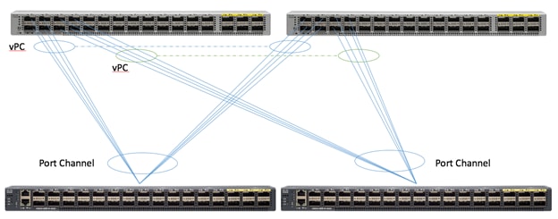
Figure 22 shows the connectivity between the Cisco UCS C240 M4 servers and the Fabric Interconnect pairs.
Figure 22 Cisco UCS C240 M4 Server Connectivity
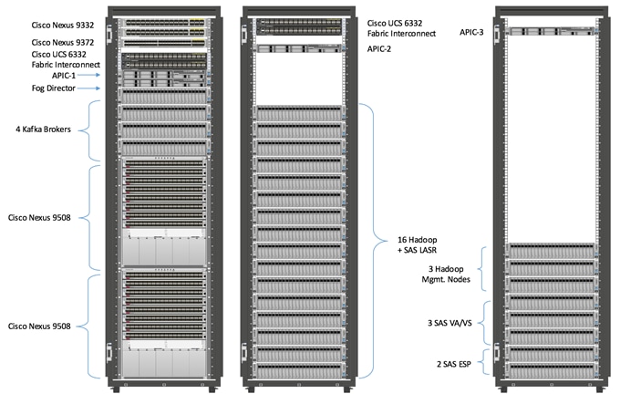
The physical layout for the solution is shown in Figure 23. Each rack consists of two vertical PDUs. The solution consists of three Cisco R42610 racks.
All switches for the ACI fabric are in rack 1, as well as one APIC appliance. Four Cisco UCS C240 M4 servers acting as Kafka nodes are also in rack one, as is one Cisco UCS C220 M4 server for fog node management. Finally, two fabric interconnects are mounted in rack one.
The second rack houses two fabric interconnects; one APIC appliance and 16 Cisco UCS C240 M4 servers used for the HDFS data and SAS LASR nodes.
The third rack houses the final APIC appliance and eight C240 M4 servers for: Hadoop management (3 nodes), SAS Visual Analytics / Visual Statistics (3 nodes), and SAS Event Stream Processing Server (2 servers).
The Cisco IR829G routers are not shown, as they are not rack mounted. Each Cisco IR829G router is connected to the 9372 leaf switch via 1 x 1GE link using 1/10 GE adapter.
In this design, the Cisco UCS C220 running the Cisco Fog Director software is connected directly to the Fabric Interconnects. In actual practice this server may be anywhere that is appropriate to managing the edge devices.
Figure 23 Reference Architecture-Physical Layout
Configuration of APIC
This section describes loading and configuring the APIC.
When the APIC appliance is booted for the first time, the APIC console presents a series of initial setup options. For many options, you can press Enter to choose the default setting that is displayed in brackets. At any point in the setup dialog, you can restart the dialog from the beginning by pressing Ctrl-C.
To configure APIC, complete the following steps:
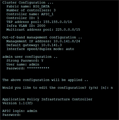
1. Enter the fabric name [ACI Fabric1]:
2. Enter the number of controllers in the fabric (1-9) [3]:3
3. Enter the controller ID (1-3) [1]:1
4. Enter the controller name [apic1]:APIC_1
5. Enter address pool for TEP addresses [10.0.0.0/16]: 155.155.0.0/16
6. Enter the VLAN ID for infra network (1-4094) [4]: 2000
7. Out-of-band management configuration.
8. Enter the IP address for out-of-band management: 10.0.141.8/24
9. Enter the IP address of the default gateway [None]: 10.0.141.1
10. Administrator user configuration.
11. Enable strong passwords? [Y]
12. Enter the password for admin.
A screenshot of the configuration is shown below.
13. Repeat steps 1 through 12 for the additional 2 APICs with unique IP addresses for each of them.
When the configuration is completed, the APIC will Boot its APIC IOS Image and will ask for the login information. The default username is "admin" and the password is the one that was set during the initial configuration.
Switch Discovery with the APIC
The APIC is a central point of automated provisioning and management for all the switches that are part of the ACI fabric. A single data center might include multiple ACI fabrics, each with their own APIC cluster and Cisco Nexus 9000 Series switches that are part of the fabric. To ensure that a switch is managed only by a single APIC cluster, each switch must be registered with that specific APIC cluster that manages the fabric. The APIC discovers new switches that are directly connected to any switch it currently manages. Each APIC instance in the cluster first discovers only the leaf switch to which it is directly connected. After the leaf switch is registered with the APIC, the APIC discovers all spine switches that are directly connected to the leaf switch. As each spine switch is registered, that APIC discovers all the leaf switches that are connected to that spine switch. This cascaded discovery allows the APIC to discover the entire fabric topology in a few simple steps.
Switch Registration with the APIC Cluster
When the switch is discovered by the APIC cluster it needs to be registered in the APIC to make it as a part of the fabric.
Prerequisite: All switches must be physically connected and booted with the correct ACI Image.
To register the switch with the APIC cluster, complete the following steps:
1. Using a web browser, connect to the out-of-band management IP address [10.0.141.8] configured in the initial configuration.
2. On the menu bar, choose FABRIC > INVENTORY. In the Navigation pane, choose the appropriate pod.
3. In the Navigation pane, expand the pod, and click Fabric Membership.
In the Work pane, in the Fabric Membership table, a single leaf switch is displayed with an ID of 0. It is the leaf switch that is connected to APIC.
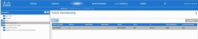
To configure the ID, double-click the leaf switch row, and complete the following steps:
1. In the ID field, add the appropriate ID (leaf1 is ID 101, leaf2 is ID 102 and leaf3 is ID103).
![]() For the purpose of this CVD, only two leaf nodes have been used. Leaf3 added here is only for demonstration.
For the purpose of this CVD, only two leaf nodes have been used. Leaf3 added here is only for demonstration.
The ID must be a number that is greater than 100 because the first 100 IDs are for APIC appliance nodes.
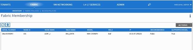
2. In the Switch Name field, add the name of the switch, and click Update.
After an ID is assigned, it cannot be updated. The switch name can be updated by double-clicking the name and updating the Switch Name field.
The Success dialog box is displayed. An IP address is assigned to the switch, and in the Navigation pane, the switch is displayed under the pod.
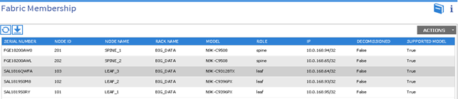
Monitor the Work pane until one or more spine switches appear.
To configure the ID, double-click the spine switch row and complete the following steps:
1. In the ID field, add the appropriate ID (spine1 is ID 201 and spine 2 is ID 202). The ID must be a number that is greater than 100.
2. In the Switch Name field, add the name of the switch, and click Update. The Success dialog box is displayed. An IP address is assigned to the switch, and in the Navigation pane, the switch is displayed under the pod. Wait until all remaining switches appear in the Node Configurations table.
For each switch listed in the Fabric Membership table, complete the following steps:
1. Double-click the switch, enter an ID and a Name, and click Update.
2. Repeat these steps for the next switch in the list.
Validating the Switches
To validate the switches, complete the following steps:
1. On the menu bar, choose Fabric > Inventory, and in the Navigation pane, under Pod 1, expand Fabric Membership.
2. The switches in the fabric are displayed with their node IDs. In the Work pane, all the registered switches are displayed with the IP addresses that are assigned to them.
Validating the Fabric Topology
To validate the fabric topology, complete the following steps:
1. On the menu bar, choose Fabric > Inventory.
2. In the Navigation pane, choose the pod that you want to view.
3. In the Work pane, click the Topology tab.
4. The displayed diagram shows all attached switches, APIC instances, and links.
5. (Optional) To view the port-level connectivity of a leaf switch or spine switch, double-click its icon in the topology diagram.
6. To return to the topology diagram, in the upper left corner of the Work pane click the Previous View icon.
7. (Optional) To refresh the topology diagram, in the upper left corner of the Work pane, click the Refresh icon.
Adding Management Access
Attach Entity Profiles (AEP)
The ACI fabric provides multiple attachment points that connect through leaf ports to various external entities such as bare metal servers, hypervisors, Layer 2 switches (for example, the Cisco UCS Fabric Interconnect), and Layer 3 routers (for example Cisco Nexus 7000 Series switches). These attachment points can be physical ports, port channels, or a virtual port channel (vPC) on the leaf switches.
An attachable entity profile (AEP) represents a group of external entities with similar infrastructure policy requirements. The infrastructure policies consist of physical interface policies, for example, Cisco Discovery Protocol (CDP), Link Layer Discovery Protocol (LLDP), maximum transmission unit (MTU), and Link Aggregation Control Protocol (LACP).
An AEP is required to deploy any VLAN pools on the leaf switches. It is possible to reuse the encapsulation pools (for example, VLAN) across different leaf switches. An AEP implicitly provides the scope of the VLAN pool (associated to the VMM domain) to the physical infrastructure.
![]() An AEP provisions the VLAN pool (and associated VLANs) on the leaf. The VLANs are not actually enabled on the port. No traffic flows unless an EPG is deployed on the port. Without VLAN pool deployment using an AEP, a VLAN is not enabled on the leaf port even if an EPG is provisioned.
An AEP provisions the VLAN pool (and associated VLANs) on the leaf. The VLANs are not actually enabled on the port. No traffic flows unless an EPG is deployed on the port. Without VLAN pool deployment using an AEP, a VLAN is not enabled on the leaf port even if an EPG is provisioned.
![]() A particular VLAN is provisioned or enabled on the leaf port based on EPG events either statically binding on a leaf port or based on VM events from external controllers such as VMware vCenter.
A particular VLAN is provisioned or enabled on the leaf port based on EPG events either statically binding on a leaf port or based on VM events from external controllers such as VMware vCenter.
![]() A leaf switch does not support overlapping VLAN pools. Different overlapping VLAN pools must not be associated with the same AEP.
A leaf switch does not support overlapping VLAN pools. Different overlapping VLAN pools must not be associated with the same AEP.
Network Configuration and ACI Setup
The network configuration includes configuring the APIC, leaf, spine switches and Fabric Interconnect and deploying various application profiles and policies. In order to achieve this we first need to register the connected Nexus 9K switches to the APIC so that these switches become the part of the ACI fabric. When the switch is registered the communication between the spine and leaf are completed.
The admin is the only account enabled by default after the APIC is configured and it is always a good practice to create other user accounts with different privilege levels to make the APIC and the network secure. For this purpose, we create a local or remote user depending on requirement.
Adding a management access is required in the ACI to let ACI know about any physical or virtual domain that is connected to it. By adding management access, APIC will control the physical interface and assign the policies to this interface. This is achieved by configuring Attachable Access Entity Profile (AEP). AEP requires having the domain and VLAN pool that the ACI fabric will be using to communicate with various devices attached to it.
![]() For more detail on AEP, see section Adding Management Access.
For more detail on AEP, see section Adding Management Access.
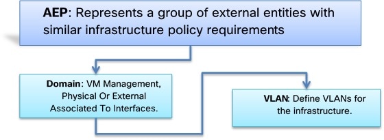
In this CVD, two pair of FIs representing two domains are connected to the pair of leaf switch. The uplink in the FIs is connected to the leaf via the port channeling (created in FI) and vPC is created at the leaf switches. The vPC allows single device to use a PortChannel across two upstream devices, eliminating Spanning Tree Protocol blocked ports which in turns provides a loop-free topology. With the use of vPC provides high availability and link-level resiliency.
Depending on the number of VLANs created in the FI, to trunk these vlans across the ACI fabric an Attachable Entity Profile (AEP) is required. An AEP provisions the VLAN pool (and associated VLANs) on the leaf, these VLAN pools are defined under the domain created within the AEP. A domain could be various external entities such as bare metal servers, hypervisors, VM management, Layer 2 or Layer 3 domains. The VLANs are not actually enabled on the port. No traffic flows unless an EPG is deployed on the port. An EPG acts as a separate entity which is analogous to VLAN. A tenant needs to be created before an EPG is defined.
A tenant contains policies that enable qualified users domain-based access control. Application profile, security policies and network are the elements of Tenants. An EPG for each VLAN is created under the application profile. Since EPG represent VLANs, a switch virtual interface (SVI) is needed to provide the Layer 3 processing for packets from all switch ports associated with the VLAN. A bridge domain needs to be created which acts as switch virtual interface (SVI) for this purpose. Now, for the inter-Vlan communication, contracts need to be created to achieve communication among each EPG. Contracts are policies that enable inter-End Point Group (inter-EPG) communication. These policies are the rules that specify communication between application tiers.
![]() For more details about Tenants, see section Creating Tenants, Private Networks, and Bridge Domains.
For more details about Tenants, see section Creating Tenants, Private Networks, and Bridge Domains.
The relationship between the AEP, Tenants and its elements is shown in Figure 24.
Figure 24 AEP, Tenants, and Elements
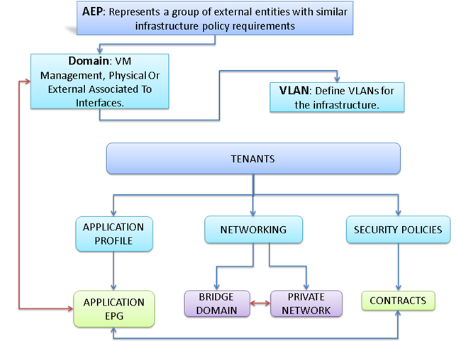
Configuring VPC Ports for Fabric Interconnect
In order to configure vPC, you need to create the CDP Policy, LLDP Policy, and LACP Policy that can be applied to the vPC ports.
· The APIC does not manage fabric interconnects and the rack servers, so these services must be configured from Cisco UCS Manager.
· Create VLAN pools that are associated on the fabric interconnect uplink to the leaf switch on the fabric interconnect.
· Cisco UCS C-series server when used along with ACI, Link Layer Discovery Protocol (LLDP) is not supported and must be disabled.
· Cisco Discovery Protocol (CDP) is disabled by default in the Cisco UCS Manager Fabric Interconnects. In the Cisco UCS Manager, you must enable CDP by creating a policy under Network Control Policies > CDP.
The above steps are explained in the following section.
Creating CDP Policy Group
To create the CDP Policy Group, complete the following steps:
1. On the menu bar, choose Fabric > Access Policies.
2. In the Navigation pane, expand the Interface Policies and expand the Policies again.
3. Right-click CDP Interface and select "Create CDP Interface Policy."
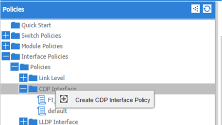
4. In the Create CDP Interface Policy dialogue box, enter Hadoop_CDP as the policy name, set Admin State to Enabled and click Submit.
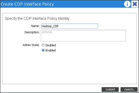
Creating LLDP Policy Group
To create the LLDP Policy Group, complete the following steps:
1. On the menu bar, choose Fabric > Access Policies.
2. In the Navigation pane, expand the Interface Policies and expand the Policies again.
3. Right-click LLDP Interface and select "Create LLDP Interface Policy."
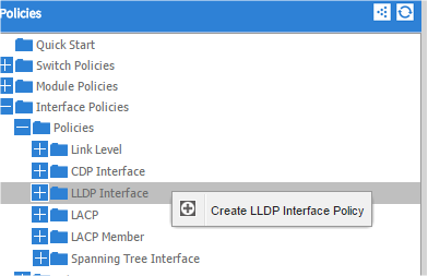
4. In the Create LLDP Interface Policy dialogue box, enter "Hadoop_LLDP" as the policy name, set both the Receive and Transmit State "Disabled" and click Submit.
This will create the LLDP policy group.
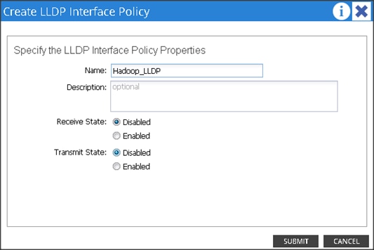
Creating LACP Policy
To create the LACP Policy, complete the following steps:
1. On the menu bar, choose Fabric > Access Policies.
2. In the Navigation pane, expand the Interface Policies and expand the Policies again.
3. Right-click Port Channel Policies and select "Create Port Channel Policy."
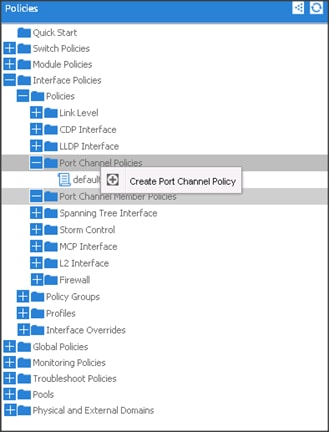
4. In the Create Port Channel Policy window, enter the name LACP_Active. In the mode select the Active radio button and click Submit.
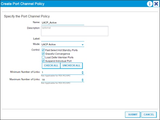
Create a Physical Domain and VLAN Pool
To create a physical domain and VLAN pool, complete the following steps:
1. On the menu bar, choose Fabric > Access Policies.
2. In the Navigation pane, expand the Physical and External Domain and expand the Physical Domain again.
3. Right-click Physical Domain and select "Create Physical Domain."
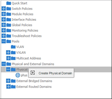
4. In the Create Physical Domain windows, in the Name field enter "Hadoop."
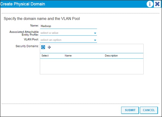
5. In the VLAN Pool drop down list choose Create VLAN Pool.
6. In the Create VLAN Pool windows, in the name field enter Hadoop.
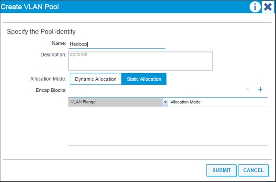
7. In the allocation mode choose Static Allocation.
8. Click "+" in the Encap Blocks area to create a Range of Vlans.
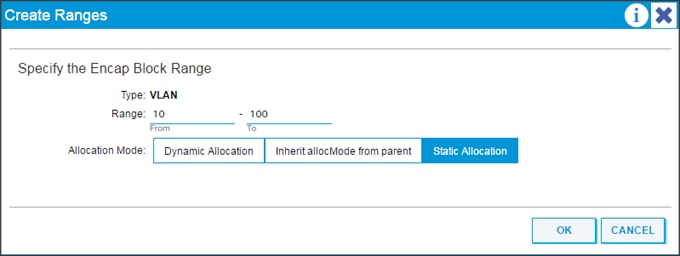
9. In the create Range window, enter vlan id 10 to 100.
10. In the Allocation mode select Static Allocation and click OK.
11. Click Submit in the Create VLAN Pool window.
12. Click Submit in Create Physical Domain window.
Creating vPC
To create vPC, complete the following steps:
1. On the menu bar, choose Fabric > Access Policies.
2. In the quick start windows, click Configure an interface, PC, and VPC to open the configuration wizard.
3. Click the Green "+" to select the switches to configure the VPCs and perform the following actions:
a. In the Switches drop-down list, select the check boxes for the switches that you want to connect to the Fabric Interconnect. (LEAF_1 & LEAF_2).
b. In the Switch Profile Name field, enter a name for the profile FI_Connected_Leaves and click Save.
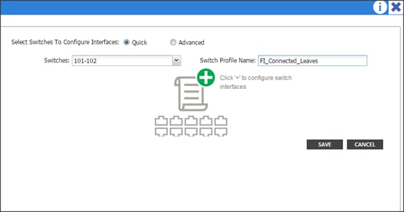
c. Click the Green "+" to configure the ports.
d. In the Interface Type area, verify the VPC radio button is selected.
e. In the Interfaces field, enter the ports where FI's are connected (in this case it is 4 ports; 1/1-4)
f. In the Interface Selector Name field, enter the name of the port profile (VPC_1).
g. In the Interface Policy Group field, choose a) Hadoop_LACP as a Port Channel Policy b) Hadoop_CDP as a CDP Policy and c) Hadoop_LLDP as a LLDP Policy.
h. In the attached Device Type drop-down list choose Bare Metal.
i. In the Domain select the Choose One radio button and in the Physical Domain drop-down list choose Hadoop and click SAVE.
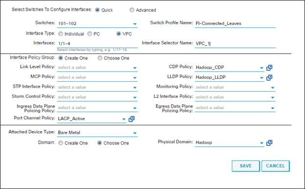
4. Repeat steps "c" to "i" to create VPC ports for all the Fabric Interconnects connected to the ACI fabric.
Configuring vPC Leaf Pairing
To configure the vPC leaf pairing, complete the following steps:
1. In the Configure Interface, PC, and VPC dialog box, click the "+" in the VPC DOMAIN ID.
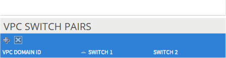
a. In the VPC Domain ID field, enter "110."
b. In the "Switch A" drop down box, select node "101."
c. In the "Switch B" drop down box, select node "102" and click Save and Submit.
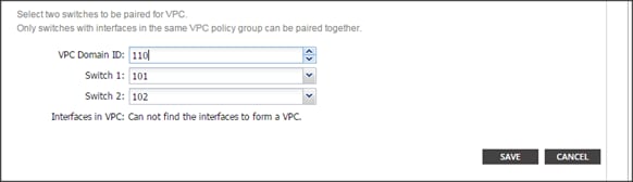
![]() The vPC created here will not come up until the port-channel in the Fabric Interconnect is created.
The vPC created here will not come up until the port-channel in the Fabric Interconnect is created.
Creating Attachable Access Entity Profiles
To create the attachable access entity profiles, complete the following steps:
1. On the Menu bar, choose Fabric > Access Policies.
2. Expand Interface Policies > Global Policies > Attachable Access Entity Profiles.
3. Right-click the Attachable Access Entity Profiles and select "Create Attachable Access Entity Profiles."
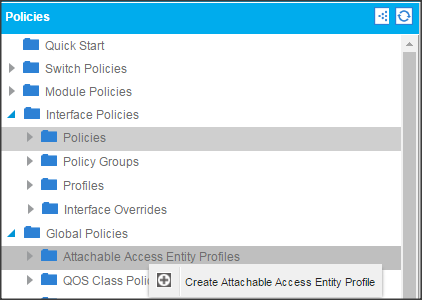
4. In the name field enter Hadoop_AEP and click next.
5. Select "All" for all the VPC ports create earlier and click Finish.
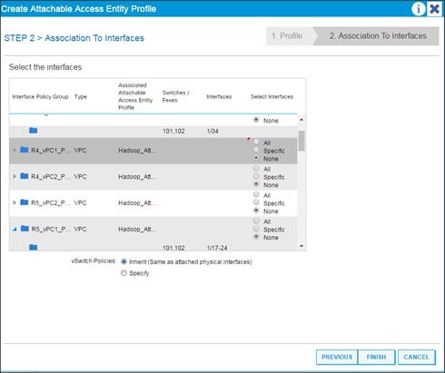
Creating Tenants, Private Networks, and Bridge Domains
Tenants Overview
· A tenant contains policies that enable qualified users domain-based access control. Qualified users can access privileges such as tenant administration and networking administration.
· A user requires read/write privileges for accessing and configuring policies in a domain. A tenant user can have specific privileges into one or more domains.
· In a multi-tenancy environment, a tenant provides group user access privileges so that resources are isolated from one another (such as for endpoint groups and networking). These privileges also enable different users to manage different tenants.
Creating a Tenant, Private Network, and Bridge Domain Using the GUI
For the purpose of this CVD, two tenants have been created named "IoT" and "Development". The tenant named "UCSDE" must be created for Cisco UCS Director Express to work in this environment. When the tenant for UCSDE is created, the other two can be created using the section below.
If the requirement is to create/remove multiple tenants several times, and is more repetitive, then this can be completely automated using Cisco UCS Director, which is described in the section Creating Tenants, Private Networks, and Bridge Domains. When the workflow is completed, no manual creation of tenants is required. The tenants can be created and removed with a few simple clicks.
Create and specify a network and a bridge domain for the tenant. The defined bridge domain element subnets reference a corresponding Layer 3 context.
To create a Tenant, Private Network, and Bridge Domain using the GUI, complete the following steps:
1. On the menu bar, choose TENANTS:
a. Click Add Tenant.
The Create Tenant dialog box opens.
b. In the Name field, add the tenant name (IoT), and click SUBMIT.
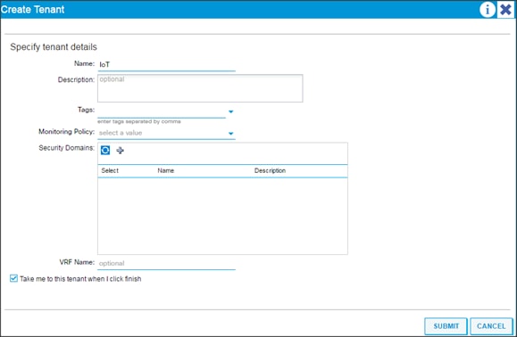
2. Go to TENANTS > IoT.
3. Expand Tenant IoT > Networking, right-click the VRFs and click Create VRFs.
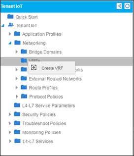
4. In the Private Network window, in the name field enter IoT and click Next.
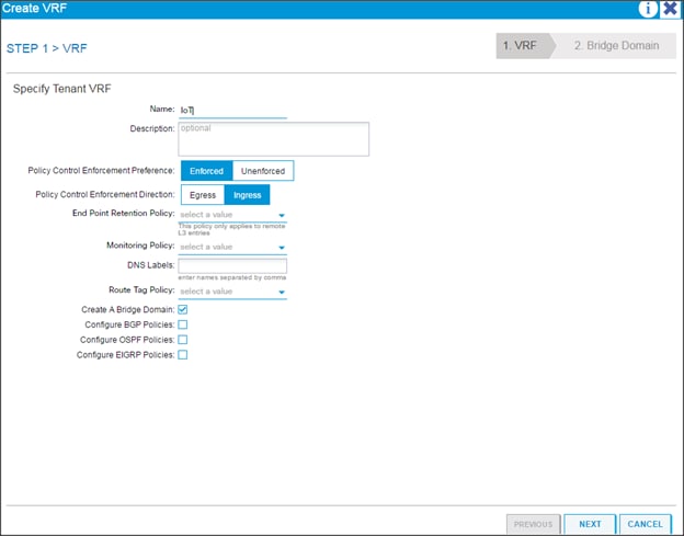
5. In the Specify Bridge Domain for the Network window, in the name field, enter IoT.
6. In the forwarding drop-down list choose Custom and click Finish.
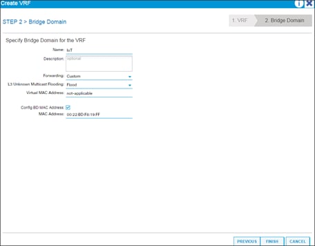
7. Go to Bridge Domains > IoT > Subnets. Click the "+" in the Subnets and enter 172.16.11.1/24 in the Gateway IP field and click Submit.
Creating an Application Profile Using the GUI
To create an application profile using the GUI, complete the following steps:
1. On the menu bar, choose Tenants > IoT. In the Navigation pane, expand the tenant, right-click Application Profiles, and click Create Application Profile.
2. In the Create Application Profile dialog box, in the Name field, add the application profile name (IoT) and click Submit.
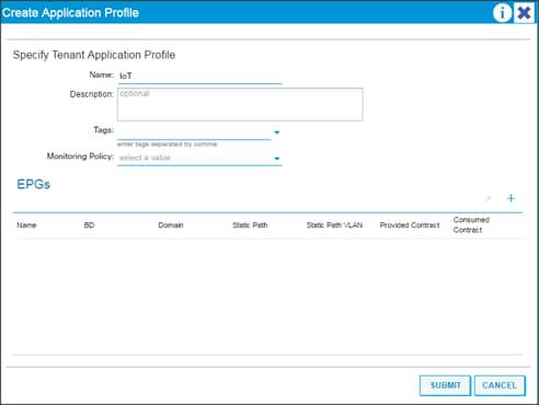
Creating EPGs Using the GUI
To create EPGs using the GUI, complete the following steps:
1. Expand Tenant IoT > Application Profiles > IoT, right-click the Application EPGs and select Create Application EPG. In the Create Application EPG dialog box, perform the following actions:
a. In the Name field, add the EPG name (IoT).
b. In the Bridge Domain field, choose the bridge domain from the drop-down list (IoT).
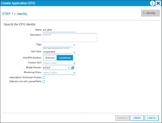
Configuring EPGs
To configure EPGs, complete the following steps:
1. Expand Tenant IoT > Application Profiles > IoT > Application EPGs > EPG IoT > Domains (VMs and Bare Metals).
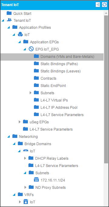
2. Click Actions and click "Add Physical Domain Association."
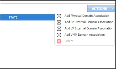
3. In the Add Physical Domain Association dialogue box, in the physical Domain profile drop-down list choose Hadoop, select the Deployment Immediacy, and Resolution Immediacy as Immediate, and click Submit.
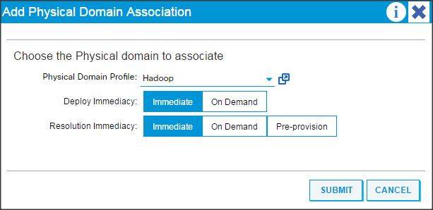
Creating the Static Bindings for the Leaves and Paths
The static bindings for the leaves are required to associate the physical interfaces with the EPGs.
No traffic flows unless an EPG is deployed on the port. Without VLAN pool deployment using an AEP, a VLAN is not enabled on the leaf port even if an EPG is provisioned. A particular VLAN is provisioned or enabled on the leaf port based on EPG events by statically binding on a leaf port.
To create the static bindings for the leaves and paths, complete the following steps:
1. On the menu bar, choose TENANTS 'IoT. In the Navigation pane, expand the tenant > Application Profiles > IoT > Application EPGs > EPG IoT and select Static Bindings (Paths).
2. Right-click Static Bindings (paths) and select Deploy Static EPG on PC, VPC, or Interface.
3. In the Path Type: select the Virtual Port Channel radio button.
4. From the Path: drop down list select the VPC_1_PolGrp. In the Encap field use vlan-41, in Deployment Immediacy select the Immediate radio button, in Mode select Tagged, and click Submit.
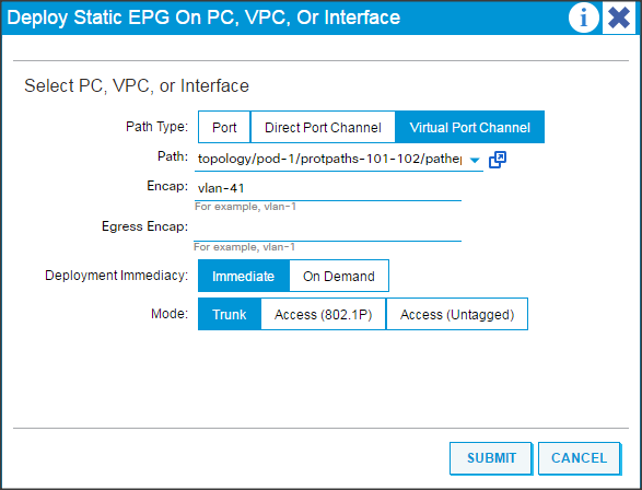
5. Repeat steps 2, 3, and 4 for all the VPC.
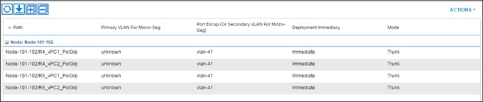
6. When the Static binding for all the EPG is configured properly, verify that the VPC ports created earlier are trunking the appropriate VLANS. This can be verified by the following steps:
a. On the menu bar, choose Fabric > Access Policies.
b. Expand Pod 1 > LEAF_1 (Node-101) > Interfaces > VPC Interfaces > 1 (this number might be different in different setups). Select any of the Interfaces to view the properties.
Configure the Ports Connected to the Cisco IR829G Routers
To configure the ports connected to the Cisco IR829G routers, complete the following steps:
1. On the menu bar, choose TENANTS > IoT. In the Navigation pane, expand the tenant > Application Profiles > IoT > Application EPGs > EPG IoT_EPG and select Static Bindings (Paths).
2. Right-click Static Bindings (paths) and select Deploy Static EPG on PC, VPC, or Interface.
3. In the Path Type: select the Port.
4. From the Path: drop-down list select the port where the Edge routers are connected. In the Encap field use vlan-41, in Deployment Immediacy select the Immediate, and in Mode select Access (802.1P) and click Submit.
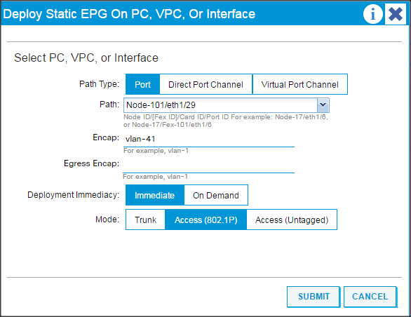
5. Repeat steps 1 through 4 to configure other ports where the routers are connected.
Router Setup and Configuration
To set up and configure the Cisco IR829G router for the deployment, complete the following steps:
1. Download the bundle package and IOX binary files from cisco.com using the links below.
a. ir800-universalk9-bundle.SPA.156-3.M0a.bin from this link:
b. ir800-ioxvm.1.2.4.2-T.bin file from this link:
2. Log in to the router copy these files to the router's flash memory:
IR800#copy tftp flash
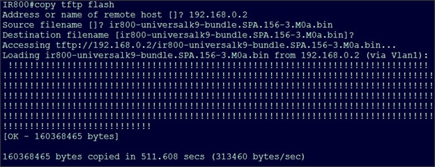
IR800#copy tftp flash
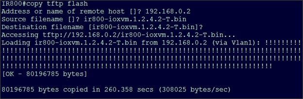
3. Install the bundle using the command below:
IR800#bundle install ir800-universalk9-bundle.SPA.156-3.M0a.bin
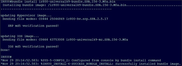
4. Save the configuration.
IR800#wr
Building configuration...
[OK]
5. Reload the router.
IR800#reload
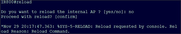
6. After the router reboots, show the hosts running on the router:
IR800#show iox host list detail
7. Stop the guest-os using the following command:
IR800#guest-os 1 stop
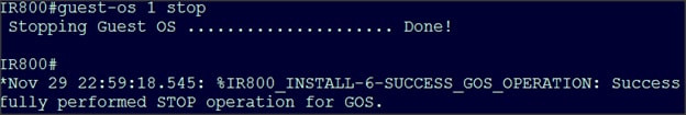
8. Uninstall the guest-os 1 image using the command
IR800#guest-os 1 image uninstall
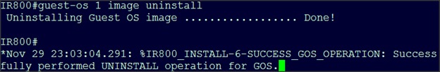
9. Install the new guest-os:
IR800#guest-os 1 image install flash:ir800-ioxvm.1.2.4.2-T.bin verify
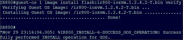
10. Start the new guest-os:
IR800#guest-os 1 start
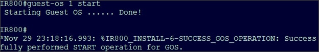
11. Check the status of the guest os by running the following command:
monit summary
12. Configure the router with the following configuration:
IR800#sh run
Building configuration...
Current configuration : 3239 bytes
!
! Last configuration change at 21:22:22 UTC Tue Nov 29 2016 by cisco
!
version 15.6
service timestamps debug datetime msec
service timestamps log datetime msec
no service password-encryption
!
hostname IR800
!
boot-start-marker
boot system flash:/ir800-universalk9-mz.SPA.156-3.M0a
boot-end-marker
!
!
!
no aaa new-model
ethernet lmi ce
service-module wlan-ap 0 bootimage autonomous
!
ignition off-timer 900
!
ignition undervoltage threshold 9
!
no ignition enable
!
!
!
!
!
!
!
!
!
!
!
!
ip dhcp excluded-address 192.168.1.1 192.168.1.5
!
ip dhcp pool gospool
network 192.168.1.0 255.255.255.0
default-router 192.168.1.1
domain-name cisco.com
dns-server 171.70.168.183 173.36.131.10
remember
!
!
!
ip domain name cisco.com
ip name-server 171.70.168.183
ip name-server 173.36.131.10
ip cef
no ipv6 cef
!
multilink bundle-name authenticated
!
!
!
chat-script lte "" "AT!CALL" TIMEOUT 20 "OK"
!
!
license udi pid IR829GW-LTE-VZ-AK9 sn FTX2040Z02U
!
!
username cisco privilege 15 password 0 cisco
!
redundancy
!
!
!
!
!
controller Cellular 0
lte sim max-retry 0
lte modem link-recovery rssi onset-threshold -110
lte modem link-recovery monitor-timer 20
lte modem link-recovery wait-timer 10
lte modem link-recovery debounce-count 6
!
!
!
!
!
!
!
!
!
!
!
interface Loopback0
ip address 10.0.0.1 255.255.255.255
!
interface GigabitEthernet0
no ip address
shutdown
!
interface GigabitEthernet1
no ip address
!
interface GigabitEthernet2
no ip address
!
interface GigabitEthernet3
no ip address
!
interface GigabitEthernet4
no ip address
!
interface Wlan-GigabitEthernet0
no ip address
!
interface GigabitEthernet5
ip address 192.168.1.1 255.255.255.0
ip nat inside
ip virtual-reassembly in
duplex auto
speed auto
ipv6 enable
!
interface Cellular0
no ip address
encapsulation slip
dialer in-band
dialer string lte
!
interface wlan-ap0
no ip address
!
interface Vlan1
ip address 192.168.0.1 255.255.255.0
ip nat outside
ip virtual-reassembly in
!
interface Async0
no ip address
encapsulation scada
!
interface Async1
no ip address
encapsulation scada
!
!
ip forward-protocol nd
!
no ip http server
no ip http secure-server
!
ip nat inside source list NAT_ACL interface Vlan1 overload
ip nat inside source static tcp 192.168.1.6 8443 interface Vlan1 8443
ip nat inside source static tcp 192.168.1.6 22 interface Vlan1 2222
!
ip access-list standard NAT_ACL
permit 192.168.0.0 0.0.255.255
!
ipv6 ioam timestamp
!
!
!
control-plane
!
!
!
!
line con 0
stopbits 1
line 1 2
stopbits 1
line 3
script dialer lte
no exec
transport preferred lat pad telnet rlogin lapb-ta mop udptn v120 ssh
transport output lat pad telnet rlogin lapb-ta mop udptn v120 ssh
line 4
no activation-character
no exec
transport preferred none
transport input all
transport output lat pad telnet rlogin lapb-ta mop udptn v120 ssh
line 1/3
transport preferred none
transport output none
stopbits 1
line 1/4
transport preferred none
transport input all
transport output none
stopbits 1
line 1/5 1/6
transport preferred none
transport output none
stopbits 1
line vty 0 4
password cisco
login local
transport input all
!
no scheduler max-task-time
ntp update-calendar
ntp server ntp.esl.cisco.com
!
!
!
!
!
!
end
13. Log in to the local manager through the browser using the IP 192.168.0.1 to verify the setup.
Fabric Configuration
This section provides details for configuring a fully redundant, highly available Cisco UCS 6332 fabric configuration. Follow this procedure twice, once for each domain: one domain with 16 Cisco UCS C240 M4 servers; the other with four Cisco UCS C240 M4 servers and one Cisco UCS C220 M4 server.
![]() Note: This document describes setting up the maximum number of nodes the FI supports. Use 16 nodes and five nodes as needed.
Note: This document describes setting up the maximum number of nodes the FI supports. Use 16 nodes and five nodes as needed.
· Initial setup of the Fabric Interconnect A and B.
· Connect to UCS Manager using virtual IP address of the web browser.
· Launch UCS Manager.
· Enable server and uplink ports.
· Start discovery process.
· Create pools and polices for service profile template.
· Create Service Profile template and Service Profiles for each node
· Associate Service Profiles to servers.
Performing Initial Setup of Cisco UCS 6332 Fabric Interconnects
This section describes the initial setup of the Cisco UCS 6332 Fabric Interconnects A and B.
Configure Fabric Interconnect A
1. Connect to the console port on the first Cisco UCS 6332 Fabric Interconnect.
2. At the prompt to enter the configuration method, enter console to continue.
3. If asked to either perform a new setup or restore from backup, enter setup to continue.
4. Enter y to continue to set up a new Fabric Interconnect.
5. Enter y to enforce strong passwords.
6. Enter the password for the admin user.
7. Enter the same password again to confirm the password for the admin user.
8. When asked if this fabric interconnect is part of a cluster, answer y to continue.
9. Enter A for the switch fabric.
10. Enter the cluster name for the system name.
11. Enter the Mgmt0 IPv4 address.
12. Enter the Mgmt0 IPv4 netmask.
13. Enter the IPv4 address of the default gateway.
14. Enter the cluster IPv4 address.
15. To configure DNS, answer y.
16. Enter the DNS IPv4 address.
17. Answer y to set up the default domain name.
18. Enter the default domain name.
19. Review the settings that were printed to the console, and if they are correct, answer yes to save the configuration.
20. Wait for the login prompt to make sure the configuration has been saved.
Configure Fabric Interconnect B
1. Connect to the console port on the second Cisco UCS 6332 Fabric Interconnect.
2. When prompted to enter the configuration method, enter console to continue.
3. The installer detects the presence of the partner Fabric Interconnect and adds this fabric interconnect to the cluster. Enter y to continue the installation.
4. Enter the admin password that was configured for the first Fabric Interconnect.
5. Enter the Mgmt0 IPv4 address.
6. Answer yes to save the configuration.
7. Wait for the login prompt to confirm that the configuration has been saved.
For more information about configuring Cisco UCS 6300 Series Fabric Interconnect, see:
Logging into Cisco UCS Manager
To login to Cisco UCS Manager, complete the following steps:
1. Open a Web browser and navigate to the Cisco UCS 6332 Fabric Interconnect cluster address.
2. Click the Launch link to download the Cisco UCS Manager software.
3. If prompted to accept security certificates, accept as necessary.
4. When prompted, enter admin for the username and enter the administrative password.
5. Click Login to log in to the Cisco UCS Manager.
Adding a Block of IP Addresses for KVM Access
To create a block of KVM IP addresses for server access in the Cisco UCS environment, complete the following steps:
1. Select the LAN tab at the top of the left window.
2. Select Pools > IP Pools > Ip Pool ext-mgmt.
3. Right-click IP Pool ext-mgmt.
4. Select Create Block of IPv4 Addresses.
5. Adding a Block of IPv4 Addresses for KVM Access Part 1.
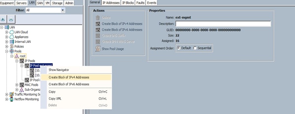
6. Enter the starting IP address of the block and number of IPs needed, as well as the subnet and gateway information.
7. Adding Block of IPv4 Addresses for KVM Access Part 2.
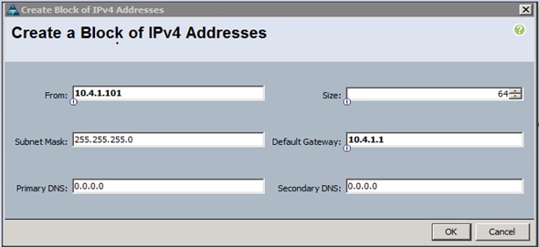
8. Click OK to create the IP block.
9. Click OK in the message box.
Configuring VLANs
Table 6 lists the VLAN configuration.
| VLAN |
NIC Port |
| VLAN19 |
eth0 |
The NIC will carry the data traffic from VLAN19. A single vNIC is used in this configuration and the Fabric Failover feature in Fabric Interconnects will take care of any physical port down issues. It will be a seamless transition from an application perspective.
To configure VLANs in the Cisco UCS Manager GUI, complete the following steps:
1. Select the LAN tab in the left pane in the Cisco UCS Manager GUI.
2. Select LAN > LAN Cloud > VLANs.
3. Right-click the VLANs under the root organization.
4. Select Create VLANs to create the VLAN.
5. Creating a VLAN.
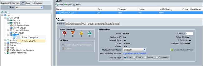
6. Enter vlan19 for the VLAN Name.
7. Keep multicast policy as <not set>.
8. Select Common/Global for vlan19.
9. Enter 19 in the VLAN IDs field for the Create VLAN IDs.
10. Click OK and then click Finish.
11. Click OK in the success message box.
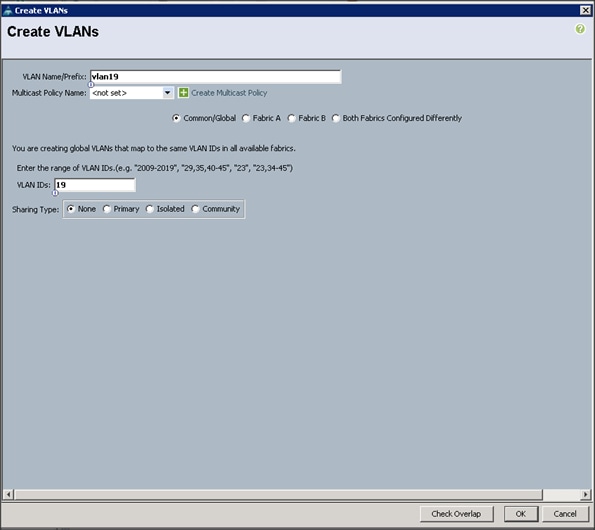
12. Click OK and then click Finish.
Enabling Server Ports
To enable server ports, complete the following steps:
1. Select the Equipment tab on the top left of the window.
2. Select Equipment > Fabric Interconnects > Fabric Interconnect A (primary) > Fixed Module.
3. Expand the Unconfigured Ethernet Ports section.
4. Select all the ports that are connected to the servers and right-click them, and select Reconfigure > Configure as a Server Port.
5. A pop-up window appears to confirm your selection. Click Yes then OK to continue.
6. Select Equipment > Fabric Interconnects > Fabric Interconnect B (subordinate) > Fixed Module > Ethernet Ports.
7. Select all the ports that are connected to the Servers, right-click them, and select Reconfigure > Configure as a Server Port.
8. A pop-up window appears to confirm your selection. Click Yes, then OK to continue.
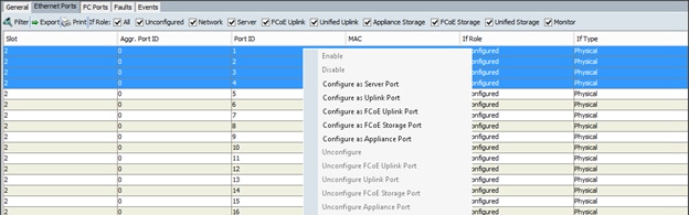
Enabling Uplink Ports
To enable uplink ports, complete the following steps:
1. Select the Equipment tab on the top left of the window.
2. Select Equipment > Fabric Interconnects > Fabric Interconnect A (primary) > Fixed Module > Ethernet Ports.
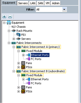
3. On the Right window select all the ports that are connected to the Nexus 9332 leaf switch (8 per FI), right-click them, and select > Configure as uplink Port.
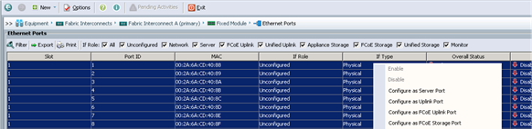
4. Select Equipment > Fabric Interconnects > Fabric Interconnect B (subordinate) > Fixed Module.
5. Expand the Unconfigured Ethernet Ports section.
6. Select all the ports that are connected to the Nexus 9332 leaf switch (8 per FI), right-click them, and select > Configure as uplink Port.
![]() Note: The ports that are configured as uplink port should appear as Network under interface role.
Note: The ports that are configured as uplink port should appear as Network under interface role.
Configuring Port Channels
To configure port channels, complete the following steps:
1. Select the LAN tab on top left window.
2. Expand the LAN Cloud > Fabric A.
3. On the right window select Create Port Channel.
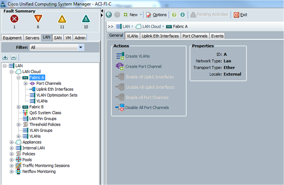
4. On Set Port Channel Name window, complete the following steps:
a. In the ID field, specify the ID "01" as the first port channel.
b. In Name field, type P01 as Port-channel01 and click Next.
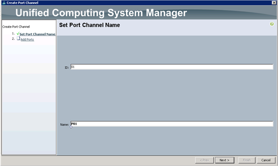
5. In the Add Ports window, select all the ports that is connected to the Nexus 9396 Leaf Switch and click >>. This will add all the ports in the port channel created earlier.

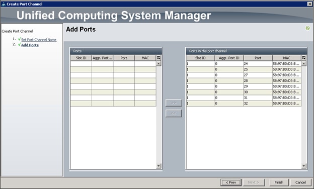
6. Similarly for Fabric Interconnect B, select the LAN tab on top left window.
7. Expand the LAN Cloud > Fabric B.
8. In the right window, select Create Port Channel.
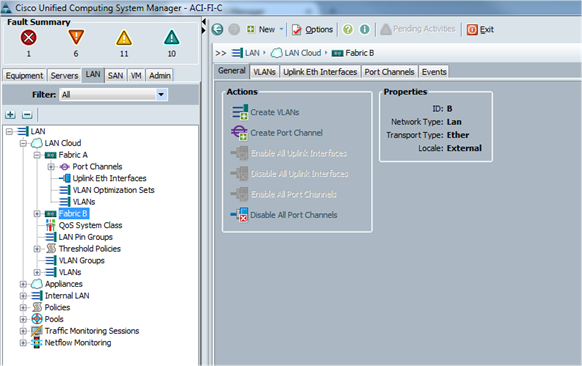
9. On Set Port Channel Name window, complete the following steps:
a. In the ID field, specify the ID "02" as the second port channel.
b. In Name field, type P02 as Port-channel01 and click Next.
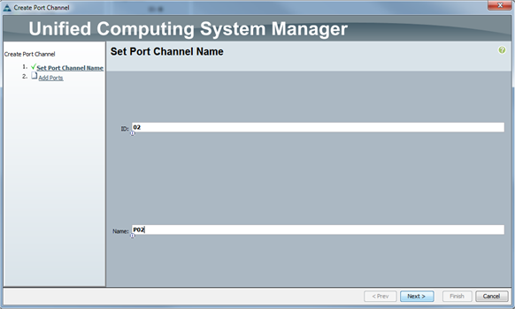
10. In the Add Ports window, select all the ports that are connected to the Nexus 9396 Leaf Switch and click >>. This will add all the ports into the port channel created earlier.
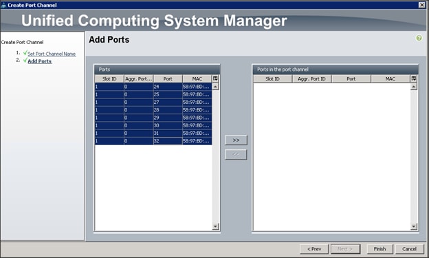
Creating Pools for Service Profile Templates
Creating an Organization
Organizations are used as a means to arrange and restrict access to various groups within the IT organization, thereby enabling multi-tenancy of the compute resources. This document does not assume the use of Organizations; however the necessary steps are provided for future reference.
To configure an organization within the Cisco UCS Manager GUI, complete the following steps:
1. Click New on the top left corner in the right pane in the Cisco UCS Manager GUI.
2. Select Create Organization from the options.
3. Enter a name for the organization.
4. (Optional) Enter a description for the organization.
5. Click OK.
6. Click OK in the success message box.
Creating MAC Address Pools
To create MAC address pools, complete the following steps:
1. Select the LAN tab on the left of the window.
2. Select Pools > root.
3. Right-click MAC Pools under the root organization.
4. Select Create MAC Pool to create the MAC address pool. Enter ucs for the name of the MAC pool.
5. (Optional) Enter a description of the MAC pool.
6. Select Assignment Order Sequential.
7. Click Next.
8. Click Add.
9. Specify a starting MAC address.
10. Specify a size of the MAC address pool, which is sufficient to support the available server resources.
11. Click OK.
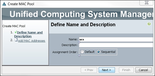
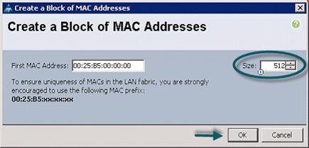
12. Click Finish.
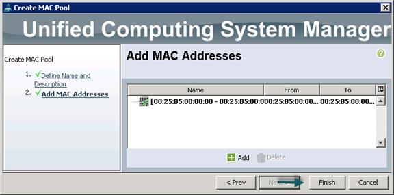
13. When the message box displays, click OK.
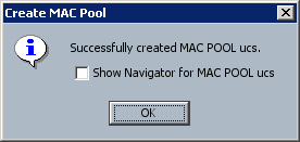
Creating a Server Pool
A server pool contains a set of servers. These servers typically share the same characteristics. Those characteristics can be their location in the chassis, or an attribute such as server type, amount of memory, local storage, type of CPU, or local drive configuration. You can manually assign a server to a server pool, or use server pool policies and server pool policy qualifications to automate the assignment
To configure the server pool within the Cisco UCS Manager GUI, complete the following steps:
1. Select the Servers tab in the left pane in the Cisco UCS Manager GUI.
2. Select Pools > root.
3. Right-click the Server Pools.
4. Select Create Server Pool.
5. Enter your required name (ucs) for the Server Pool in the name text box.
6. (Optional) enter a description for the organization.
7. Click Next > to add the servers.
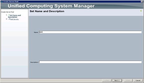
8. Select all the Cisco UCS C240M4SX servers to be added to the server pool that was previously created (ucs), then click >> to add them to the pool.
9. Click Finish.
10. Click OK and then click Finish.
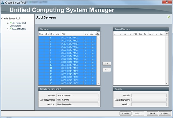
Creating Policies for Service Profile Templates
Creating Host Firmware Package Policy
Firmware management policies allow the administrator to select the corresponding packages for a given server configuration. These include adapters, BIOS, board controllers, FC adapters, HBA options, and storage controller properties as applicable.
To create a firmware management policy for a given server configuration using the Cisco UCS Manager GUI, complete the following steps:
1. Select the Servers tab in the left pane in the Cisco UCS Manager GUI.
2. Select Policies > root.
3. Right-click Host Firmware Packages.
4. Select Create Host Firmware Package.
5. Enter the required Host Firmware package name (ucs).
6. Select Simple radio button to configure the Host Firmware package.
7. Select the appropriate Rack package that has been installed.
8. Click OK to complete creating the management firmware package
9. Click OK.
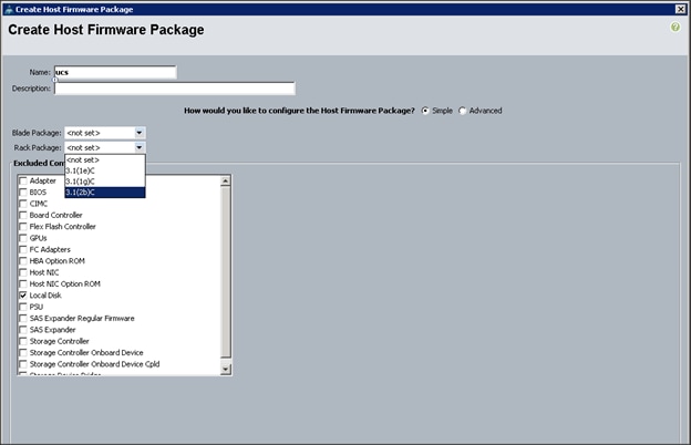
Creating QoS Policies
To create the QoS policy for a given server configuration using the Cisco UCS Manager GUI, complete the following steps:
Platinum Policy
1. Select the LAN tab in the left pane in the Cisco UCS Manager GUI.
2. Select Policies > root.
3. Right-click QoS Policies.
4. Select Create QoS Policy.
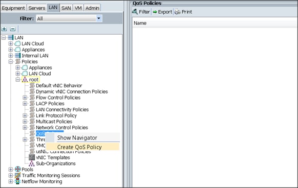
5. Enter Platinum as the name of the policy.
6. Select Platinum from the drop down menu.
7. Keep the Burst(Bytes) field set to default (10240).
8. Keep the Rate(Kbps) field set to default (line-rate).
9. Keep Host Control radio button set to default (none).
10. When the pop-up window appears, click OK to complete the creation of the Policy.
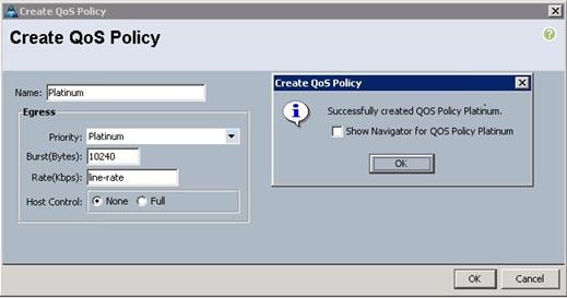
Setting Jumbo Frames
To set Jumbo frames and enable QoS, complete the following steps:
1. Select the LAN tab in the left pane in the Cisco UCS Manager GUI.
2. Select LAN Cloud > QoS System Class.
3. In the right pane, select the General tab
4. In the Platinum row, enter 9216 for MTU.
5. Check the Enabled Check box next to Platinum.
6. In the Best Effort row, select none for weight.
7. In the Fiber Channel row, select none for weight.
8. Click Save Changes.
9. Click OK.
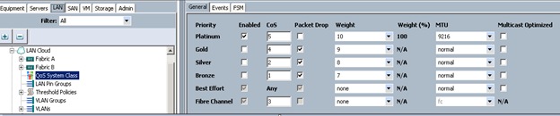
Creating the Local Disk Configuration Policy
To create local disk configuration in the Cisco UCS Manager GUI, complete the following steps:
1. Select the Servers tab on the left pane in the Cisco UCS Manager GUI.
2. Go to Policies > root.
3. Right-click Local Disk Config Policies.
4. Select Create Local Disk Configuration Policy.
5. Enter ucs as the local disk configuration policy name.
6. Change the Mode to Any Configuration. Check the Protect Configuration box.
7. Keep the FlexFlash State field as default (Disable).
8. Keep the FlexFlash RAID Reporting State field as default (Disable).
9. Click OK to complete the creation of the Local Disk Configuration Policy.
10. Click OK.
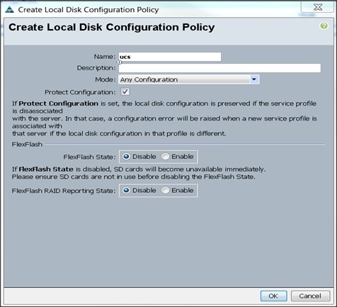
Creating Server BIOS Policy
The BIOS policy feature in Cisco UCS automates the BIOS configuration process. The traditional method of setting the BIOS is manually, and is often error-prone. By creating a BIOS policy and assigning the policy to a server or group of servers, can enable transparency within the BIOS settings configuration.
![]() Note: BIOS settings can have a significant performance impact, depending on the workload and the applications. The BIOS settings listed in this section is for configurations optimized for best performance which can be adjusted based on the application, performance, and energy efficiency requirements.
Note: BIOS settings can have a significant performance impact, depending on the workload and the applications. The BIOS settings listed in this section is for configurations optimized for best performance which can be adjusted based on the application, performance, and energy efficiency requirements.
To create a server BIOS policy using the Cisco UCS Manager GUI, complete the following steps:
1. Select the Servers tab in the left pane in the Cisco UCS Manager GUI.
2. Select Policies > root.
3. Right-click BIOS Policies.
4. Select Create BIOS Policy.
5. Enter your preferred BIOS policy name (ucs).
6. Change the BIOS settings as shown in the following figures.
7. The only changes that need to be made are in the Processor and RAS Memory settings.
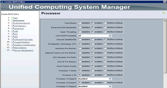
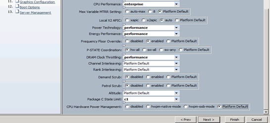
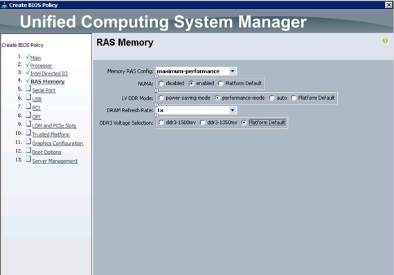
Creating the Boot Policy
To create boot policies within the Cisco UCS Manager GUI, complete the following steps:
1. Select the Servers tab in the left pane in the Cisco UCS Manager GUI.
2. Select Policies > root.
3. Right-click the Boot Policies.
4. Select Create Boot Policy.
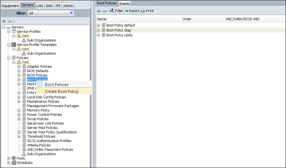
5. Enter ucs as the boot policy name.
6. (Optional) enter a description for the boot policy.
7. Keep the Reboot on Boot Order Change check box unchecked.
8. Keep Enforce vNIC/vHBA/iSCSI Name check box checked.
9. Keep Boot Mode Default (Legacy).
10. Expand Local Devices > Add CD/DVD and select Add Local CD/DVD.
11. Expand Local Devices and select Add Local Disk.
12. Expand vNICs and select Add LAN Boot and enter eth0.
13. Click OK to add the Boot Policy.
14. Click OK.
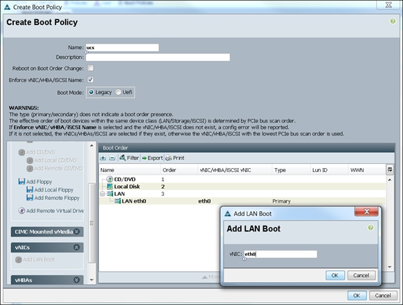
Creating Power Control Policy
To create Power Control policies within the Cisco UCS Manager GUI, complete the following steps:
1. Select the Servers tab in the left pane in the Cisco UCS Manager GUI.
2. Select Policies > root.
3. Right-click the Power Control Policies.
4. Select Create Power Control Policy.
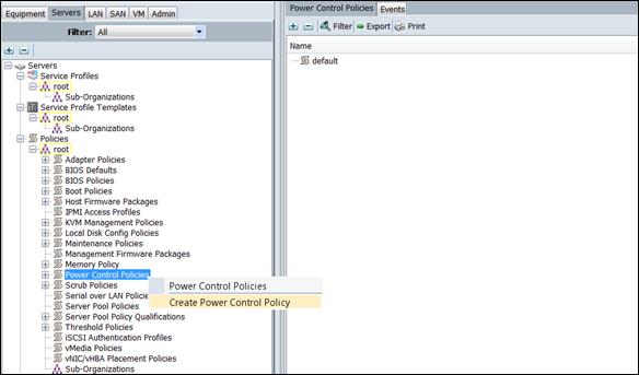
5. Enter ucs as the Power Control policy name.
6. (Optional) enter a description for the boot policy.
7. Select Performance for Fan Speed Policy.
8. Select No cap for Power Capping selection.
9. Click OK to create the Power Control Policy.
10. Click OK.
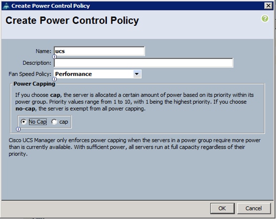
Creating a Service Profile Template
To create a Service Profile Template, complete the following steps:
1. Select the Servers tab in the left pane in the Cisco UCS Manager GUI.
2. Right-click Service Profile Templates.
3. Select Create Service Profile Template.
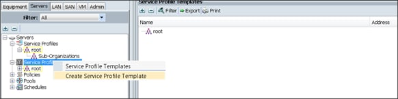
The Create Service Profile Template window appears.
To identify the service profile template, complete the following steps:
4. Name the service profile template as ucs. Select the Updating Template radio button.
5. In the UUID section, select Hardware Default as the UUID pool.
6. Click Next to continue to the next section.
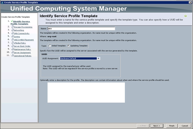
Configuring the Storage Provisioning for the Template
To configure storage policies, complete the following steps:
1. Go to the Local Disk Configuration Policy tab, and select ucs for the Local Storage.
2. Click Next to continue to the next section.
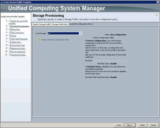
3. Click Next when the Networking window appears to proceed to the next section.
Configuring Network Settings for the Template
To configure the network setting for the template, complete the following steps:
1. Keep the Dynamic vNIC Connection Policy field at the default.
2. Select Expert radio button for the option how would you like to configure LAN connectivity?
3. Click Add to add a vNIC to the template.
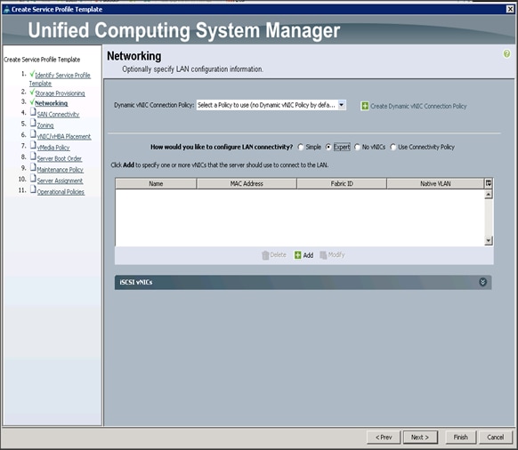
4. The Create vNIC window displays. Name the vNIC as eth0.
5. Select ucs in the Mac Address Assignment pool.
6. Select the Fabric A radio button and check the Enable failover check box for the Fabric ID.
7. Check the VLAN19 check box for VLANs and select the Native VLAN radio button.
8. Select MTU size as 9000.
9. Select adapter policy as Linux.
10. Select QoS Policy as Platinum.
11. Keep the Network Control Policy as Default.
12. Click OK.
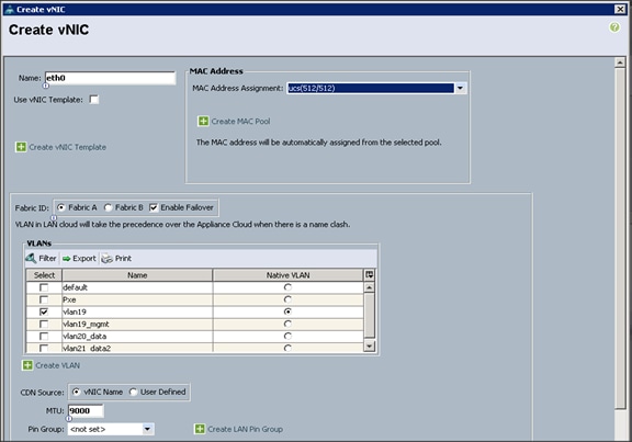
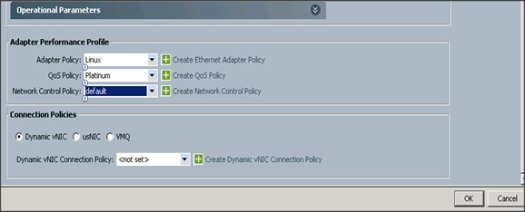
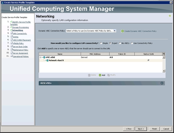
![]() Note: Optionally Network Bonding can be setup on the vNICs for each host for redundancy as well as for increased throughput.
Note: Optionally Network Bonding can be setup on the vNICs for each host for redundancy as well as for increased throughput.
13. Click Next to continue with SAN Connectivity.
14. Select no vHBAs for How would you like to configure SAN Connectivity?
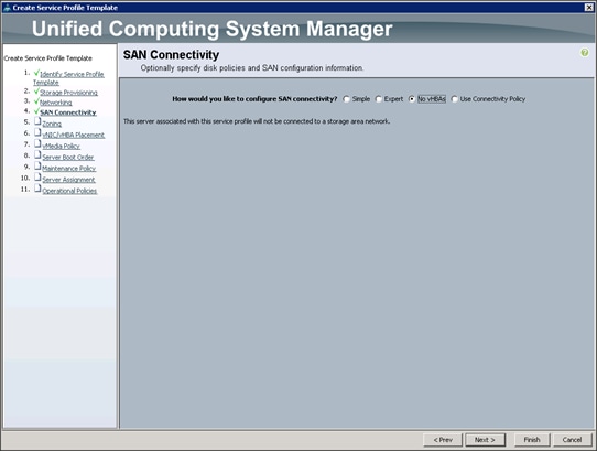
15. Click Next to continue with Zoning.
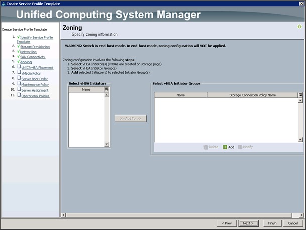
16. Click Next to continue with vNIC/vHBA placement.
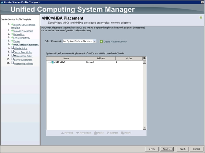
17. Click Next to configure vMedia Policy.
Configuring the vMedia Policy for the Template
To configure the vMedia policy for the template, complete the following steps:
1. Click Next when the vMedia Policy window appears to proceed to the next section.
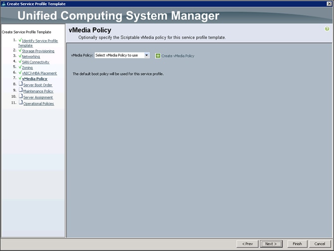
Configuring Server Boot Order for the Template
To set the boot order for the servers, complete the following steps:
1. Select ucs in the Boot Policy name field.
2. Review to make sure that all of the boot devices were created and identified.
3. Verify that the boot devices are in the correct boot sequence.
4. Click OK.
5. Click Next to continue to the next section.
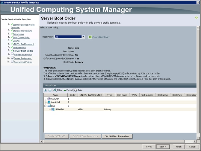
6. In the Maintenance Policy window, apply the maintenance policy.
7. Keep the Maintenance policy at no policy used by default. Click Next to continue to the next section.
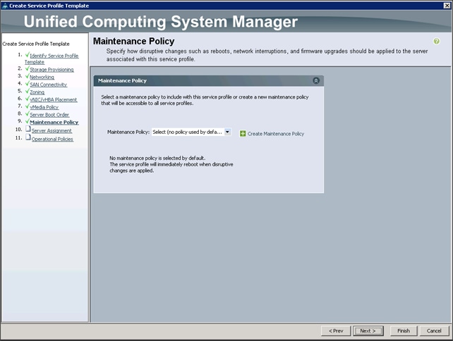
Configuring Server Assignment for the Template
To configure the server assignment for the template, complete the following steps:
1. In the Server Assignment window, to assign the servers to the pool, complete the following steps:
2. Select ucs for the Pool Assignment field.
3. Select the power state to be Up.
4. Keep the Server Pool Qualification field set to <not set>.
5. Check the Restrict Migration check box.
6. Select ucs in Host Firmware Package.
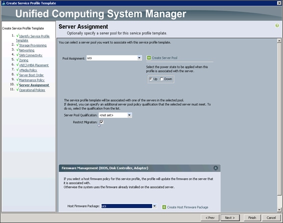
Configuring Operational Policies for the Template
In the Operational Policies Window, complete the following steps:
1. Select ucs in the BIOS Policy field.
2. Select ucs in the Power Control Policy field.
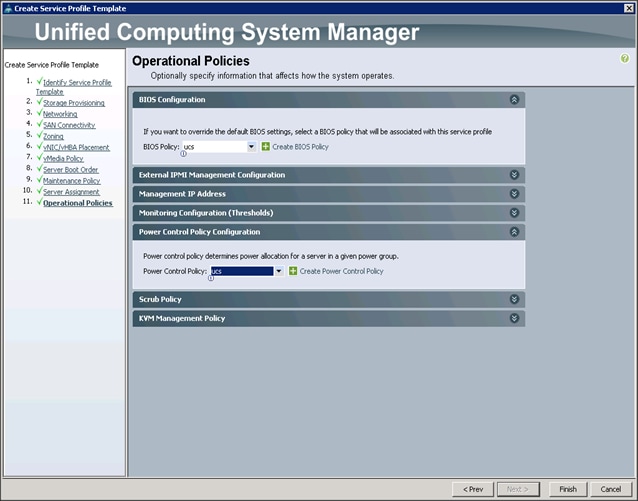
3. Click Finish to create the Service Profile template.
4. Click OK in the pop-up window to proceed.
5. Select the Servers tab in the left pane of the Cisco UCS Manager GUI.
6. Go to Service Profile Templates > root.
7. Right-click Service Profile Templates ucs.
8. Select Create Service Profiles From Template.
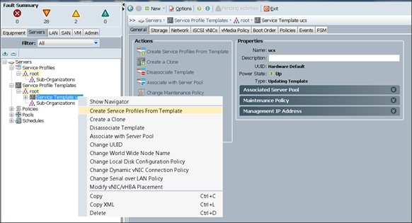
The Create Service Profiles from Template window appears.
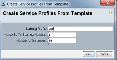
Association of the Service Profiles will take place automatically.
The final Cisco UCS Manager window is shown in below.
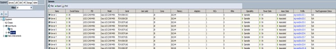
To install Red Hat Enterprise Linux 7.2, please follow the instructions in this Cisco Validated Design document:
Cisco UCS for SAS Visual Analytics
To install Cloudera Enterprise 5.7, please follow the instructions in this Cisco Validated Design document:
Cisco UCS for SAS Visual Analytics
To install SAS LASR Analytic Server, Visual Analytics, and Visual Statistics, please follow the instructions in this Cisco Validated Design document:
Cisco UCS for SAS Visual Analytics
Cloudera Manager 5.4 or higher includes the Kafka service. To install, download Kafka using Cloudera Manager, distribute Kafka to the cluster, activate the new parcel, and add the service to the cluster.
To download the Kafka Parcels, on a server that is accessible to the internet, complete the following steps:
1. Create a directory for the Kafka parcels:
#mkdir /tmp/Kafka
#cd /tmp/Kafka
#wget http://archive.cloudera.com/kafka/parcels/2.0.2/KAFKA-2.0.2-1.2.0.2.p0.5-el6.parcel
#wget http://archive.cloudera.com/kafka/parcels/2.0.2/KAFKA-2.0.2-1.2.0.2.p0.5-el6.parcel.sha1
#wget http://archive.cloudera.com/kafka/parcels/2.0.1/manifest.json
2. Change the contents of manifest.json to match the following:
{
"lastUpdated": 14680135200000,
"parcels": [
{
"parcelName": "KAFKA-2.0.2-1.2.0.2.p0.5-el6.parcel",
"components": [
{
"pkg_version": "0.9.0+kafka2.0.2",
"pkg_release": "1.2.0.2.p0.5",
"name": "kafka",
"version": "0.9.0-kafka2.0.2"
}
],
"depends": "CDH (>= 5.2), CDH (<< 6.0)",
"replaces": "CLABS_KAFKA",
"hash": "ed82fc7a20f12181e858e5e63707a65eeb4e45f9"
}
]
}
3. Copy the Kafka parcels over to rhel1 under /var/www/html:
#scp -r Kafka rhel1:/var/www/html/
4. From the browser, go to the parcels at http://172.16.21.11:7180/cmf/parcel/status.
5. Click Configure. Add a new parcel by clicking the "+" and provide the path to the new Kafka parcels that were downloaded in the previous step.
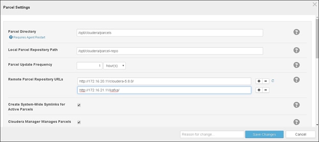
6. Click Save Changes.
7. Click Download and then click Distribute to download and distribute the parcels.
8. Click Activate to add the service to the cluster.
When Activation is complete, the Kafka service is ready to be installed on the Cluster.
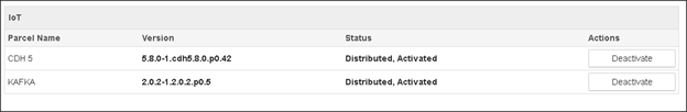
Kafka Installation
To install Kafka, complete the following steps:
1. Click the arrow next to the cluster name and select Add Service.
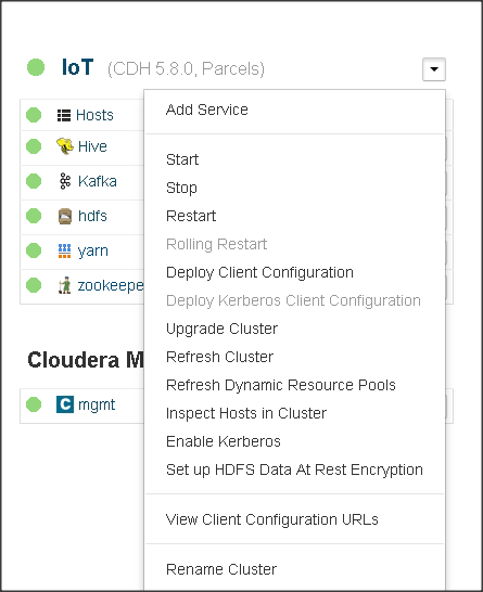
2. This screen lists all the available services. Select Kafka from the list.
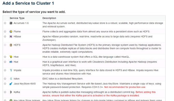
3. Click Continue to proceed with the installation.
4. Select the hosts on which the Kafka Broker(s) need to be enabled. In this CVD, Kafka is enabled only on four nodes.
5. The Default Replication Factor in Kafka is 1; change that to 3 and click Continue to enable the services.
6. Change the broker_max_heap_size to 512MB.
![]() Note: Kafka MirrorMaker is needed for when dealing with multiple Kafka clusters to replicate data across data centers.
Note: Kafka MirrorMaker is needed for when dealing with multiple Kafka clusters to replicate data across data centers.
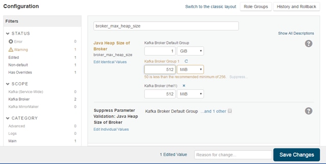
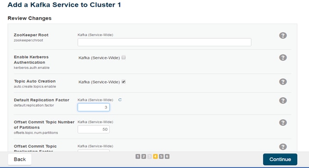
7. Click Continue to start the service.
Kafka works well for smaller messages and the best performance occurs with 1 KB messages. Refer to the link below for further performance and resource tuning configurations for Kafka: http://www.cloudera.com/documentation/kafka/latest/topics/kafka_performance.html
Cisco Fog Director is installed on the Cisco UCS C220 M4 server. First, install the VMware vSphere Hypervisor and then install the Fog Director software.
Hypervisor Installation
The following instructions assume the VMware vSphere Hypervisor has already been installed. For more information, see: http://www.cisco.com/c/en/us/td/docs/unified_computing/ucs/UCS_CVDs/HaaS_on_Bare_Metal_with_UCSDExpress_on_Cisco_UCS_Integrated_Infrastructure_for_Big_Data_and_ACI.html#_Toc449348026
After the Hypervisor is installed, configure the network with the following VLAN:
vlan ID = 41
name = IoT
Installing Cisco Fog Director
To install Cisco Fog Director in VMware vSphere Hypervisor, complete the following steps:
Before You Begin
· Review the information in section Software Requirements.
· Make sure that you have a valid Cisco.com user ID and password, which are required to obtain the VM OVA image for installation
1. From a system connected the internet, download the VM OVA image:
b. Click Download that corresponds to the OVA image file that you want.
c. Follow the onscreen instructions to download the file to your local drive.
2. From a client PC, use the VMware vSphere Hypervisor client application to log in o your VMWare host on the Cisco UCS C220 M4 server.
3. From the File menu, choose Deploy OVF Template. The Deploy OVF Template Wizard starts.
4. In the Deploy OVF Template Wizard, complete the following steps:
a. In the Deploy OVF Template window, locate to and select the Fog Director OVF template that you downloaded and then click Next.
b. In the OVF Template Details window, click Next.
c. In the Name and Location window enter "cisco-fog-director" and click Next.
d. In the Datastore window, click the datastore in which to install the OVA files and then click Next.
e. In the Host / Cluster window, click Next.
f. In the Specify a Specific Host window, click Next.
g. In the Disk Format window, click Next.
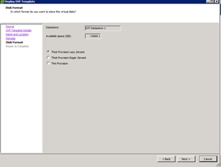
h. In the Network Mapping window, select 'IoT' and click Next.
i. In the Ready to Complete window, click Finish.
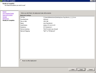
The installation begins.
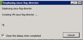
5. When the Deployment Completed Successfully window appears, click Close. The installation is complete.
Configuring the Network for Cisco Fog Director
To configure the network for Cisco Fog Director, complete the following steps:
1. Log into the VM on which you installed Cisco Fog Director using the default login credentials: username = fogdir, password=fogdir
2. Use the sudo vi command to open the /etc/network/interfaces file.
3. In the interfaces file, update the following fields as needed:
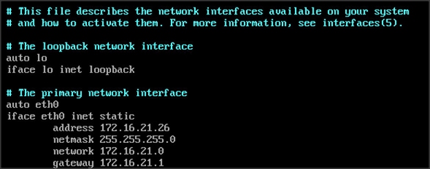
4. Save the interfaces file and reboot the VM.
5. Make sure you can connect to Fog Director by opening a browser and entering this URL: https://172.16.21.26
6. The default username and password is admin/admin. The system will ask you to change the password.
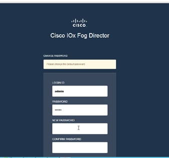
For more information about Cisco Fog Director, see: http://www.cisco.com/c/en/us/td/docs/routers/access/800/software/guides/iox/fog-director/reference-guide/1-0/fog_director_ref_guide.pdf
Configuring Cisco Fog Director to Connect to the Routers
To add the routers that Cisco Fog Director will manage, log into Cisco Fog Director and complete the following steps:
1. Click the Devices tab at the top of the window.
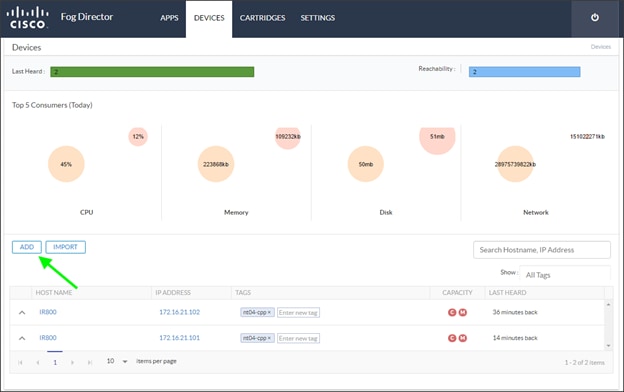
2. Click Add.
3. Enter the IP address, port, and credentials for the router.
4. Click Save & Add More to continue adding more routers. Click Save & Close when finished.
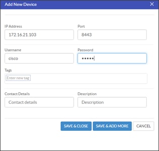
Introduction
SAS Event Stream Processing enables developers to build applications that can quickly process and analyze a large number of continuously flowing events in real time. The deployment installs the programming tools that are required to build and execute event stream processing applications.
SAS Event Stream Processing 4.1 was the first release to include compatibility with the SAS Viya platform and to use the same deployment tools and process. SAS Event Stream Processing 4.2 enhances the deployment experience and adds multiple features. When installed along with the Cloud Analytic Services (CAS) components, SAS Event Stream Processing can provide data for analytic processing in SAS Viya.
However, SAS Event Stream Processing can still be installed as a standalone product without SAS Viya. Use this guide to deploy SAS Event Stream Processing in your environment.
![]() Note: To use this guide successfully, you should have a working knowledge of the Linux operating system and basic commands.
Note: To use this guide successfully, you should have a working knowledge of the Linux operating system and basic commands.
SAS Repositories
To make sure that you deploy the latest software, SAS provides the SAS Event Stream Processing software in repository packages that are maintained by SAS. Specifically, the software is packaged in the RPM Package Manager (RPM) format, which simplifies installation, uninstallation, and upgrade tasks. Each time you deploy or update your software, you automatically receive the latest RPM packages that are available.
![]() Note: The RPM-based deployment model works with repositories that are native to your operating system. As a result, a SAS Software Depot is no longer required in your environment.
Note: The RPM-based deployment model works with repositories that are native to your operating system. As a result, a SAS Software Depot is no longer required in your environment.
Industry Standard Tools
You can now deploy SAS Event Stream Processing with tools that are designed for deploying and updating software on Linux operating systems. SAS Viya deployment takes advantage of yum, a software package manager for Linux operating systems. Yum commands are used for secure access to RPM packages and for deploying and updating software in your environment.
![]() Note: The SAS Deployment Wizard and the SAS Deployment Manager that supported SAS 9.4 are not used to install and configure SAS Event Stream Processing 4.2.
Note: The SAS Deployment Wizard and the SAS Deployment Manager that supported SAS 9.4 are not used to install and configure SAS Event Stream Processing 4.2.
Linux Prerequisites
SAS Viya deployment requires the operating system to be registered with the Red Hat Network. Registration enables you to receive periodic software updates. For a SAS software deployment, registration also enables yum to download software from SAS repositories. Verify that the machine where you perform the deployment (typically, the Ansible controller) is registered and that your subscription has been activated.
To check whether the system is registered, run the following command:
subscription-manager version
The command returns information about the subscription service to which the system is registered. To check whether the subscription has been activated, run the following command:
subscription-manager list --installed
If the subscription has been activated, the following message is displayed: "subscribed to Red Hat Enterprise Linux Server".
If you have enabled Security-Enhanced Linux (SELinux) in your environment, you must also enable permissive mode on all of the machines on which you install SAS software. SELinux is not supported by SAS Viya.
To find out whether SELinux is enabled on your system, run the following command:
sudo sestatus
If the mode that is returned is not permissive, run the following commands to enable permissive mode:
sudo setenforce 0
sudo sed -i.bak -e 's/SELINUX=enforcing/SELINUX=permissive/g' /etc/selinux/config
The typical Linux installation includes all of the packages and libraries that SAS requires. Problems can occur if default packages were removed from the base operating system (for example, X11 libraries and system utilities). The following libraries are required:
· libXp
· libXmu
· glibc 2.12
· the numactl package
· the X11/Xmotif (GUI) packages
Additional Linux Requirements
The SAS Event Stream Processing Engine libraries were built using gcc-4.4.7-16 and the Boost library 1.58. The Boost library 1.58 is automatically installed along with SAS Event Stream Processing. The libraries are compiled using the following compiler options:
-D_REENTRANT
-D_THREAD_SAFE
All of the SAS Event Stream Processing applications that you build with SAS Event Stream Processing Studio must also use the same compiler options.
The SAS Event Stream Processing 4.x libraries have been built using gcc-4.4.7-16 on Red Hat Enterprise Linux Server 6.7 using libc-2.12.so, libstdc++.so.6.0.13 and libgcc_s-4.4.7-20120601.so.1
Software Requirements
Java Requirements
The Java Runtime Environment (JRE) must be installed on each machine where you install SAS Event Stream Processing components. The following versions are supported:
· Oracle JRE SE version 8.x
· OpenJDK version 1.8.x
User Accounts
Verify the following prerequisites before you start the deployment:
· Administrator privileges for the Linux machine where you are launching the SAS software deployment are required.
· The user account that you are using for the deployment must have super user (sudo) access. To verify that the user ID is included in the sudoers file, run the following command:
sudo -v
To verify your sudoers privileges, run the following command:
sudo -l
![]() Note: The ability to start a shell (with the !SHELL entry in some sudoers files) as root is not required.
Note: The ability to start a shell (with the !SHELL entry in some sudoers files) as root is not required.
Create two users; sas and sasuser with sudoers privileges. Assign them to the group: sas.
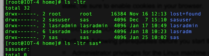
During the software deployment, one required user account (sas) and one group (also named sas) are created for you unless they already exist. Because the sas account is required for the SAS Event Stream Processing Studio component to run during normal product operation, you must not delete it or change its name. It does not run as root. If you must log on to this account, use sudo to access it.
Table 7 describes the predefined SAS user account:
Table 7 SAS User Account Descriptions
| Account Name and Group |
Parameters |
Purpose |
| sas; member of sas group |
UID: 1002 Group ID: 1001 Non-login service account without user restrictions. No password; can add password after installation if desired. Password does not expire. Default user name is required until the installation is complete. Any post-installation changes to this account do not prevent future software updates that use SAS RPM packaging. |
Required for the installation. The installation process sets user and group ownership permissions on all of the installation files. This user must exist to enable ownership. After the installation has completed, this user account enables required components to run, including the web application server for SAS Event Stream Processing Studio. |
Administrator privileges are not required after the installation to run SAS Event Stream Processing Engine. The installation directory path enables write access per user group, and it is owned by the sas user. To grant permission to edit the configuration files, the administrator must add any user requiring write access to these files to the sas group.
Pre-configuration Requisites for Installing SAS ESP 4.2
Disable iptables (host-based firewall)
[root@IOT-4 ~]# service iptables stop
iptables: Setting chains to policy ACCEPT: filter [ OK ]
iptables: Flushing firewall rules: [ OK ]
iptables: Unloading modules: [ OK ]
[root@IOT-4 ~]# chkconfig iptables off
[root@IOT-4 ~]# chkconfig --list iptables
iptables 0:off 1:off 2:off 3:off 4:off 5:off 6:off
[root@IOT-5 ~]# service iptables stop
iptables: Setting chains to policy ACCEPT: filter [ OK ]
iptables: Flushing firewall rules: [ OK ]
iptables: Unloading modules: [ OK ]
[root@IOT-5 ~]# chkconfig iptables off
[root@IOT-5 ~]# chkconfig --list iptables
iptables 0:off 1:off 2:off 3:off 4:off 5:off 6:off
Disable SELinux
[root@IOT-4 ~]# setenforce 0
[root@IOT-4 ~]# sed -i.20161208 -e 's/SELINUX=enforcing/SELINUX=disabled/g' /etc/selinux/config
[root@IOT-4 ~]# diff /etc/selinux/config /etc/selinux/config.20161208
7c7
< SELINUX=disabled
---
> SELINUX=enforcing
[root@IOT-5 ~]# setenforce 0
[root@IOT-5 ~]# sed -i.20161208 -e 's/SELINUX=enforcing/SELINUX=disabled/g' /etc/selinux/config
[root@IOT-5 ~]# diff /etc/selinux/config /etc/selinux/config.20161208
7c7
< SELINUX=disabled
---
> SELINUX=enforcing
Configure DNS Resolution on Hosts
[root@IOT-4 rhsm]# cat /etc/resolv.conf
nameserver 10.2.1.18
domain iote2e.cisco.com
[root@IOT-5 rhsm]# cat /etc/resolv.conf
nameserver 10.2.1.18
domain iote2e.cisco.com
Configure yum for HTTP Proxy
[root@IOT-4 rhsm]# pwd
/etc/rhsm
[root@IOT-4 rhsm]# cp rhsm.conf rhsm.conf.20161208
[root@IOT-4 rhsm]# vi rhsm.conf
[root@IOT-4 rhsm]# diff rhsm.conf rhsm.conf.20161208
22c22
< proxy_hostname = linux24.iote2e.cisco.com
---
> proxy_hostname =
25c25
< proxy_port = 3128
---
> proxy_port =
[root@IOT-5 rhsm]# pwd
/etc/rhsm
[root@IOT-5 rhsm]# cp rhsm.conf rhsm.conf.20161208
[root@IOT-5 rhsm]# vi rhsm.conf
[root@IOT-5 rhsm]# diff rhsm.conf rhsm.conf.20161208
22c22
< proxy_hostname = linux24.iote2e.cisco.com
---
> proxy_hostname =
25c25
< proxy_port = 3128
---
> proxy_port =
Subscribe to RedHat Network
[root@IOT-4 rhsm]# subscription-manager register --username kmayuram@cisco.com --password XXXXXX --auto-attach
The system has been registered with ID: e0e56612-c906-4208-8d0c-876e2bb7b240
Installed Product Current Status:
Product Name: Red Hat Enterprise Linux Server
Status: Subscribed
[root@IOT-5 rhsm]# subscription-manager register --username kmayuram@cisco.com --password XXXXXX --auto-attach
The system has been registered with ID: cc4ec851-e3b9-4c5c-bb96-aae3b7b0134b
Installed Product Current Status:
Product Name: Red Hat Enterprise Linux Server
Status: Subscribed
Add X11 Packages
[root@IOT-4 rhsm]# yum -y install xterm xauth
Loaded plugins: product-id, security, subscription-manager
Setting up Install Process
...
Running Transaction
Installing : libXmu-1.1.1-2.el6.x86_64 1/5
Installing : libXpm-3.5.10-2.el6.x86_64 2/5
Installing : libXaw-1.0.11-2.el6.x86_64 3/5
Installing : xterm-253-1.el6.x86_64 4/5
Installing : 1:xorg-x11-xauth-1.0.9-1.el6.x86_64 5/5
rhel-6-server-rpms/productid | 2.1 kB 00:00
rhel-scalefs-for-rhel-6-server-rpms/productid | 2.2 kB 00:00
Verifying : libXmu-1.1.1-2.el6.x86_64 1/5
Verifying : libXpm-3.5.10-2.el6.x86_64 2/5
Verifying : 1:xorg-x11-xauth-1.0.9-1.el6.x86_64 3/5
Verifying : libXaw-1.0.11-2.el6.x86_64 4/5
Verifying : xterm-253-1.el6.x86_64 5/5
Installed:
xorg-x11-xauth.x86_64 1:1.0.9-1.el6 xterm.x86_64 0:253-1.el6
Dependency Installed:
libXaw.x86_64 0:1.0.11-2.el6 libXmu.x86_64 0:1.1.1-2.el6
libXpm.x86_64 0:3.5.10-2.el6
Complete!
[root@IOT-4 rhsm]# which xterm xauth
/usr/bin/xterm
/usr/bin/xauth
[root@IOT-5 rhsm]# yum -y install xterm xauth
Loaded plugins: product-id, security, subscription-manager
Setting up Install Process
...
Running Transaction
Installing : libXmu-1.1.1-2.el6.x86_64 1/5
Installing : libXpm-3.5.10-2.el6.x86_64 2/5
Installing : libXaw-1.0.11-2.el6.x86_64 3/5
Installing : xterm-253-1.el6.x86_64 4/5
Installing : 1:xorg-x11-xauth-1.0.9-1.el6.x86_64 5/5
rhel-6-server-rpms/productid | 2.1 kB 00:00
rhel-scalefs-for-rhel-6-server-rpms/productid | 2.2 kB 00:00
Verifying : libXmu-1.1.1-2.el6.x86_64 1/5
Verifying : libXpm-3.5.10-2.el6.x86_64 2/5
Verifying : 1:xorg-x11-xauth-1.0.9-1.el6.x86_64 3/5
Verifying : libXaw-1.0.11-2.el6.x86_64 4/5
Verifying : xterm-253-1.el6.x86_64 5/5
Installed:
xorg-x11-xauth.x86_64 1:1.0.9-1.el6 xterm.x86_64 0:253-1.el6
Dependency Installed:
libXaw.x86_64 0:1.0.11-2.el6 libXmu.x86_64 0:1.1.1-2.el6
libXpm.x86_64 0:3.5.10-2.el6
Complete!
[root@IOT-5 rhsm]# which xterm xauth
/usr/bin/xterm
/usr/bin/xauth
Install Prerequisite OS Packages
[root@IOT-4 rhsm]# yum list libXp libXmu glibc numactl
Loaded plugins: product-id, security, subscription-manager
Installed Packages
glibc.x86_64 2.12-1.166.el6 @anaconda-RedHatEnterpriseLinux-201507020259.x86_64/6.7
libXmu.x86_64 1.1.1-2.el6 @rhel-6-server-rpms
numactl.x86_64 2.0.9-2.el6 @anaconda-RedHatEnterpriseLinux-201507020259.x86_64/6.7
Available Packages
glibc.i686 2.12-1.192.el6 rhel-6-server-rpms
glibc.x86_64 2.12-1.192.el6 rhel-6-server-rpms
libXmu.i686 1.1.1-2.el6 rhel-6-server-rpms
libXp.i686 1.0.2-2.1.el6 rhel-6-server-rpms
libXp.x86_64 1.0.2-2.1.el6 rhel-6-server-rpms
numactl.i686 2.0.9-2.el6 rhel-6-server-rpms
[root@IOT-4 rhsm]# yum -y install libXp
Loaded plugins: product-id, security, subscription-manager
Setting up Install Process
...
Installed:
libXp.x86_64 0:1.0.2-2.1.el6
Complete!
[root@IOT-5 rhsm]# yum list libXp libXmu glibc numactl
Loaded plugins: product-id, security, subscription-manager
Installed Packages
glibc.x86_64 2.12-1.166.el6 @anaconda-RedHatEnterpriseLinux-201507020259.x86_64/6.7
libXmu.x86_64 1.1.1-2.el6 @rhel-6-server-rpms
numactl.x86_64 2.0.9-2.el6 @anaconda-RedHatEnterpriseLinux-201507020259.x86_64/6.7
Available Packages
glibc.i686 2.12-1.192.el6 rhel-6-server-rpms
glibc.x86_64 2.12-1.192.el6 rhel-6-server-rpms
libXmu.i686 1.1.1-2.el6 rhel-6-server-rpms
libXp.i686 1.0.2-2.1.el6 rhel-6-server-rpms
libXp.x86_64 1.0.2-2.1.el6 rhel-6-server-rpms
numactl.i686 2.0.9-2.el6 rhel-6-server-rpms
[root@IOT-5 rhsm]# yum -y install libXp
Loaded plugins: product-id, security, subscription-manager
Setting up Install Process
...
Installed:
libXp.x86_64 0:1.0.2-2.1.el6
Complete!
Install Java OpenJDK 1.8.0
[root@IOT-4 rhsm]# yum -y install java-1.8.0-openjdk.x86_64
[root@IOT-4 rhsm]# java -version
openjdk version "1.8.0_111"
OpenJDK Runtime Environment (build 1.8.0_111-b15)
OpenJDK 64-Bit Server VM (build 25.111-b15, mixed mode)
[root@IOT-5 rhsm]# yum -y install java-1.8.0-openjdk.x86_64
[root@IOT-5 rhsm]# java -version
openjdk version "1.8.0_111"
OpenJDK Runtime Environment (build 1.8.0_111-b15)
OpenJDK 64-Bit Server VM (build 25.111-b15, mixed mode)
Installing SAS Event Stream Processing
Deploy with yum
Use the procedures in this section to deploy your SAS software using yum.
Run the Deployment Script
When you order SAS software, SAS sends a Software Order Email (SOE) to your business or organization. Your SOE includes information about the software order, including several file attachments. The following files are required for deployment:
· License file
· Certificates that enable access to your software
· customized_deployment_script.sh file, which contains customized commands that are required for accessing and downloading software from SAS repositories
To install all SAS Event Stream Processing components on the same machine, complete the following steps:
1. Open the customized deployment shell script.
2. Assign the directory path of the saved certificates to CERTDIR. The following is an example:
CERTDIR=/opt/sas/installfiles
3. Save and close the revised shell script.
4. (Optional) If you use FTP to move the files from the SOE to their final location, the customized_deployment_script.sh file might lose its execute bit. To make sure that the file has the required execute bit, run the following command:
sudo chmod +x customized_deploment_script.sh
5. Run the script:
sudo ./customized_deployment_script.sh
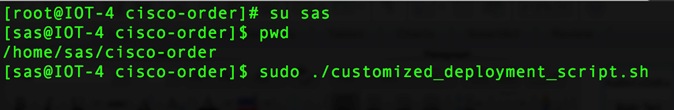
6. Run the command to install the product user interface component, SAS Event Stream Processing Studio:
sudo yum install -y sas-espvm
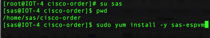
An example of the output script is shown below:
* About to connect() to ses.sas.download port 443 (#0)
* Trying 149.173.160.82... connected
* Connected to ses.sas.download (149.173.160.82) port 443 (#0)
* Initializing NSS with certpath: sql:/etc/pki/nssdb
* CAfile: /mnt/data/home/sesptest/42_release_latest_0907_0934pm/SAS_CA_Certificate.pem
CApath: none
* NSS: client certificate from file
* subject: CN=sas.download,O=SAS Institute Inc.,C=US
* start date: Sep 06 00:00:00 2016 GMT
* expire date: Sep 07 00:00:00 2026 GMT
* common name: sas.download
* issuer: E=SoftwareProductionSystems@sas.com,CN=Certificate Authority for Client Authentication,OU=Release Engineering,O="SAS Institute, Inc."
* SSL connection using TLS_RSA_WITH_AES_256_CBC_SHA
* Server certificate:
* subject: E=SoftwareProductionSystems@sas.com,CN=SES Intermediate CA,OU=Release Engineering,O=SAS Institute Inc.,L=Cary,ST=North Carolina,C=US
* start date: Mar 14 14:38:06 2016 GMT
* expire date: Mar 17 14:38:06 2026 GMT
* common name: SES Intermediate CA
* issuer: E=SoftwareProductionSystems@sas.com,CN=SES Intermediate CA,OU=Release Engineering,O=SAS Institute Inc.,ST=North Carolina,C=US
> GET /ses/repos/meta-repo//sas-meta-repo-1-1.noarch.rpm HTTP/1.1
> User-Agent: curl/7.19.7 (x86_64-redhat-linux-gnu) libcurl/7.19.7 NSS/3.18 Basic ECC zlib/1.2.3 libidn/1.18 libssh2/1.4.2
> Host: ses.sas.download
> Accept: */*
>
% Total % Received % Xferd Average Speed Time Time Time Current
Dload Upload Total Spent Left Speed
0 0 0 0 0 0 0 0 --:--:-- --:--:-- --:--:-- 0* HTTP 1.0, assume close after body
< HTTP/1.0 302 Moved
< Date: Thu, 08 Sep 2016 01:50:53 GMT
< Server: Apache/2.4.6 (Red Hat Enterprise Linux) OpenSSL/1.0.1e-fips PHP/5.4.16 mod_wsgi/3.4 Python/2.7.5
< X-Powered-By: PHP/5.4.16
< Location: https://sestest.unx.sas.com/ses/repos/meta-repo-internal//sas-meta-repo-1-1.noarch.rpm
< Content-Length: 0
< Connection: close
< Content-Type: text/html; charset=UTF-8
<
0 0 0 0 0 0 0 0 --:--:-- --:--:-- --:--:-- 0* Closing connection #0
* Issue another request to this URL: 'https://sestest.unx.sas.com/ses/repos/meta-repo-internal//sas-meta-repo-1-1.noarch.rpm'
* About to connect() to sestest.unx.sas.com port 443 (#0)
* Trying 10.15.1.107... connected
* Connected to sestest.unx.sas.com (10.15.1.107) port 443 (#0)
* CAfile: /mnt/data/home/sesptest/42_release_latest_0907_0934pm/SAS_CA_Certificate.pem
CApath: none
* NSS: client certificate from file
* subject: CN=sas.download,O=SAS Institute Inc.,C=US
* start date: Sep 06 00:00:00 2016 GMT
* expire date: Sep 07 00:00:00 2026 GMT
* common name: sas.download
* issuer: E=SoftwareProductionSystems@sas.com,CN=Certificate Authority for Client Authentication,OU=Release Engineering,O="SAS Institute, Inc."
* SSL connection using TLS_RSA_WITH_AES_256_CBC_SHA
* Server certificate:
* subject: E=SoftwareProductionSystems@sas.com,CN=SES Intermediate CA,OU=Release Engineering,O=SAS Institute Inc.,L=Cary,ST=North Carolina,C=US
* start date: Mar 14 14:38:06 2016 GMT
* expire date: Mar 17 14:38:06 2026 GMT
* common name: SES Intermediate CA
* issuer: E=SoftwareProductionSystems@sas.com,CN=SES Intermediate CA,OU=Release Engineering,O=SAS Institute Inc.,ST=North Carolina,C=US
> GET /ses/repos/meta-repo-internal//sas-meta-repo-1-1.noarch.rpm HTTP/1.0
> User-Agent: curl/7.19.7 (x86_64-redhat-linux-gnu) libcurl/7.19.7 NSS/3.18 Basic ECC zlib/1.2.3 libidn/1.18 libssh2/1.4.2
> Host: sestest.unx.sas.com
> Accept: */*
>
* HTTP 1.0, assume close after body
< HTTP/1.0 302 Moved
< Date: Thu, 08 Sep 2016 01:50:53 GMT
< Server: Apache/2.4.6 (Red Hat Enterprise Linux) OpenSSL/1.0.1e-fips PHP/5.4.16 mod_wsgi/3.4 Python/2.7.5
< X-Powered-By: PHP/5.4.16
< Location: https://sestestbw.unx.sas.com/ses/__zHA8eq7yxXc0FmyyC2yZ9bigzYznlATWsjpBgVOB5DL5yCjo/repos/meta-repo-internal//sas-meta-repo-1-1.noarch.rpm
< Content-Length: 0
< Connection: close
< Content-Type: text/html; charset=UTF-8
< Set-Cookie: BIGipServersesdev-f5.unx.sas.com=1997150218.18463.0000; path=/
<
0 0 0 0 0 0 0 0 --:--:-- --:--:-- --:--:-- 0* Closing connection #0
* Issue another request to this URL: 'https://sestestbw.unx.sas.com/ses/__zHA8eq7yxXc0FmyyC2yZ9bigzYznlATWsjpBgVOB5DL5yCjo/repos/meta-repo-internal//sas-meta-repo-1-1.noarch.rpm'
* About to connect() to sestestbw.unx.sas.com port 443 (#0)
* Trying 10.15.1.107... connected
* Connected to sestestbw.unx.sas.com (10.15.1.107) port 443 (#0)
* CAfile: /mnt/data/home/sesptest/42_release_latest_0907_0934pm/SAS_CA_Certificate.pem
CApath: none
* NSS: client certificate from file
* subject: CN=sas.download,O=SAS Institute Inc.,C=US
* start date: Sep 06 00:00:00 2016 GMT
* expire date: Sep 07 00:00:00 2026 GMT
* common name: sas.download
* issuer: E=SoftwareProductionSystems@sas.com,CN=Certificate Authority for Client Authentication,OU=Release Engineering,O="SAS Institute, Inc."
* SSL connection using TLS_RSA_WITH_AES_256_CBC_SHA
* Server certificate:
* subject: E=SoftwareProductionSystems@sas.com,CN=SES Intermediate CA,OU=Release Engineering,O=SAS Institute Inc.,L=Cary,ST=North Carolina,C=US
* start date: Mar 14 14:38:06 2016 GMT
* expire date: Mar 17 14:38:06 2026 GMT
* common name: SES Intermediate CA
* issuer: E=SoftwareProductionSystems@sas.com,CN=SES Intermediate CA,OU=Release Engineering,O=SAS Institute Inc.,ST=North Carolina,C=US
> GET /ses/__zHA8eq7yxXc0FmyyC2yZ9bigzYznlATWsjpBgVOB5DL5yCjo/repos/meta-repo-internal//sas-meta-repo-1-1.noarch.rpm HTTP/1.0
> User-Agent: curl/7.19.7 (x86_64-redhat-linux-gnu) libcurl/7.19.7 NSS/3.18 Basic ECC zlib/1.2.3 libidn/1.18 libssh2/1.4.2
> Host: sestestbw.unx.sas.com
> Accept: */*
>
< HTTP/1.1 200 OK
< Date: Thu, 08 Sep 2016 01:50:53 GMT
< Server: Apache/2.4.6 (Red Hat Enterprise Linux) OpenSSL/1.0.1e-fips PHP/5.4.16 mod_wsgi/3.4 Python/2.7.5
< X-Powered-By: PHP/5.4.16
< Accept-Ranges: bytes
< Content-Length: 9984
< Content-Disposition: attachment; filename=sas-meta-repo-1-1.noarch.rpm
< Connection: close
< Content-Type: application/octet-stream
< Set-Cookie: BIGipServersesdev-f5.unx.sas.com=1997150218.18463.0000; path=/
<
{ [data not shown]
100 9984 100 9984 0 0 66628 0 --:--:-- --:--:-- --:--:-- 66628* Closing connection #0
Loaded plugins: product-id, refresh-packagekit, rhnplugin, security,
: subscription-manager
This system is not subscribed to any channels.
RHN channel support will be disabled.
Setting up Install Process
Examining sas-meta-repo-1-1.noarch.rpm: sas-meta-repo-1-1.noarch
Marking sas-meta-repo-1-1.noarch.rpm to be installed
Resolving Dependencies
--> Running transaction check
---> Package sas-meta-repo.noarch 0:1-1 will be installed
--> Finished Dependency Resolution
Dependencies Resolved
================================================================================
Package Arch Version Repository Size
================================================================================
Installing:
sas-meta-repo noarch 1-1 /sas-meta-repo-1-1.noarch 8.8 k
Transaction Summary
================================================================================
Install 1 Package(s)
Total size: 8.8 k
Installed size: 8.8 k
Is this ok [y/N]: Downloading Packages:
Running rpm_check_debug
Running Transaction Test
Transaction Test Succeeded
Running Transaction
Installing : sas-meta-repo-1-1.noarch 1/1
Verifying : sas-meta-repo-1-1.noarch 1/1
Installed:
sas-meta-repo.noarch 0:1-1
Complete!
Loaded plugins: product-id, refresh-packagekit, rhnplugin, security,
: subscription-manager
This system is not subscribed to any channels.
RHN channel support will be disabled.
Setting up Install Process
Resolving Dependencies
--> Running transaction check
---> Package sas-esp-4.2.0-rpm-latest.noarch 0:1-1 will be installed
--> Finished Dependency Resolution
Dependencies Resolved
================================================================================
Package Arch Version Repository Size
================================================================================
Installing:
sas-esp-4.2.0-rpm-latest noarch 1-1 sas-meta-repo 3.3 k
Transaction Summary
================================================================================
Install 1 Package(s)
Total download size: 3.3 k
Installed size: 369
Is this ok [y/N]: Downloading Packages:
Running rpm_check_debug
Running Transaction Test
Transaction Test Succeeded
Running Transaction
Installing : sas-esp-4.2.0-rpm-latest-1-1.noarch 1/1
Verifying : sas-esp-4.2.0-rpm-latest-1-1.noarch 1/1
Installed:
sas-esp-4.2.0-rpm-latest.noarch 0:1-1
Complete!
Loaded plugins: product-id, refresh-packagekit, rhnplugin, security,
: subscription-manager
This system is not subscribed to any channels.
RHN channel support will be disabled.
Setting up Group Process
Resolving Dependencies
--> Running transaction check
---> Package sas-certframe.x86_64 0:3.1.11-20160826.1472229627485 will be installed
---> Package sas-crsloadstrms.x86_64 0:01.02.00-20160906.223353133220 will be installed
--> Processing Dependency: sas-tktxtan for package: sas-crsloadstrms-01.02.00-20160906.223353133220.x86_64
--> Processing Dependency: sas-tktslang for package: sas-crsloadstrms-01.02.00-20160906.223353133220.x86_64
--> Processing Dependency: sas-tktscore for package: sas-crsloadstrms-01.02.00-20160906.223353133220.x86_64
--> Processing Dependency: sas-tkcas3rdclnt for package: sas-crsloadstrms-01.02.00-20160906.223353133220.x86_64
---> Package sas-esp.x86_64 0:4.2.0-20160907.204938017564 will be installed
--> Processing Dependency: sas-tksecure for package: sas-esp-4.2.0-20160907.204938017564.x86_64
--> Processing Dependency: sas-tknls for package: sas-esp-4.2.0-20160907.204938017564.x86_64
--> Processing Dependency: sas-tkesp for package: sas-esp-4.2.0-20160907.204938017564.x86_64
--> Processing Dependency: sas-tkcore for package: sas-esp-4.2.0-20160907.204938017564.x86_64
--> Processing Dependency: sas-tk for package: sas-esp-4.2.0-20160907.204938017564.x86_64
--> Processing Dependency: sas-embscoreeng for package: sas-esp-4.2.0-20160907.204938017564.x86_64
---> Package sas-espauth.x86_64 0:4.2.0-20160907.204955116308 will be installed
--> Processing Dependency: sas-tksecuressh for package: sas-espauth-4.2.0-20160907.204955116308.x86_64
--> Processing Dependency: sas-securestrong for package: sas-espauth-4.2.0-20160907.204955116308.x86_64
--> Processing Dependency: sas-securedom for package: sas-espauth-4.2.0-20160907.204955116308.x86_64
--> Running transaction check
---> Package sas-embscoreeng.x86_64 0:02.01.00-20160725.102640062390 will be installed
--> Processing Dependency: sas-tkl4sas for package: sas-embscoreeng-02.01.00-20160725.102640062390.x86_64
--> Processing Dependency: sas-tkiog for package: sas-embscoreeng-02.01.00-20160725.102640062390.x86_64
--> Processing Dependency: sas-tkformats for package: sas-embscoreeng-02.01.00-20160725.102640062390.x86_64
--> Processing Dependency: sas-tkfnc for package: sas-embscoreeng-02.01.00-20160725.102640062390.x86_64
---> Package sas-securedom.x86_64 0:03.02.00-20160906.223232702185 will be installed
---> Package sas-securestrong.x86_64 0:03.02.00-20160906.214454054816 will be installed
---> Package sas-tk.x86_64 0:03.02.00-20160906.221932171376 will be installed
---> Package sas-tkcas3rdclnt.x86_64 0:01.02.00-20160906.221118609533 will be installed
---> Package sas-tkcore.x86_64 0:03.02.00-20160906.220532960960 will be installed
---> Package sas-tkesp.x86_64 0:01.01.00-20160906.215449068374 will be installed
---> Package sas-tknls.x86_64 0:03.02.00-20160906.221415075022 will be installed
---> Package sas-tksecure.x86_64 0:03.02.00-20160906.215353336547 will be installed
---> Package sas-tksecuressh.x86_64 0:03.02.00-20160906.215316830815 will be installed
---> Package sas-tktscore.x86_64 0:03.02.00-20160906.215330213046 will be installed
---> Package sas-tktslang.x86_64 0:03.02.00-20160906.220232904646 will be installed
---> Package sas-tktxtan.x86_64 0:03.02.00-20160906.222411476824 will be installed
--> Running transaction check
---> Package sas-tkfnc.x86_64 0:03.02.00-20160906.221948678263 will be installed
---> Package sas-tkformats.x86_64 0:03.02.00-20160906.214254159559 will be installed
---> Package sas-tkiog.x86_64 0:03.02.00-20160906.215715905415 will be installed
---> Package sas-tkl4sas.x86_64 0:03.02.00-20160906.215721652081 will be installed
--> Finished Dependency Resolution
Dependencies Resolved
================================================================================
Package Arch Version Repository Size
================================================================================
Installing:
sas-certframe
x86_64 3.1.11-20160826.1472229627485 sas-esp-4.2.0-rpm-latest 1.9 M
sas-crsloadstrms
x86_64 01.02.00-20160906.223353133220 sas-esp-4.2.0-rpm-latest 116 k
sas-esp x86_64 4.2.0-20160907.204938017564 sas-esp-4.2.0-rpm-latest 95 M
sas-espauth
x86_64 4.2.0-20160907.204955116308 sas-esp-4.2.0-rpm-latest 1.9 M
Installing for dependencies:
sas-embscoreeng
x86_64 02.01.00-20160725.102640062390 sas-esp-4.2.0-rpm-latest 1.0 M
sas-securedom
x86_64 03.02.00-20160906.223232702185 sas-esp-4.2.0-rpm-latest 425 k
sas-securestrong
x86_64 03.02.00-20160906.214454054816 sas-esp-4.2.0-rpm-latest 2.9 M
sas-tk x86_64 03.02.00-20160906.221932171376 sas-esp-4.2.0-rpm-latest 4.2 M
sas-tkcas3rdclnt
x86_64 01.02.00-20160906.221118609533 sas-esp-4.2.0-rpm-latest 700 k
sas-tkcore
x86_64 03.02.00-20160906.220532960960 sas-esp-4.2.0-rpm-latest 3.5 M
sas-tkesp x86_64 01.01.00-20160906.215449068374 sas-esp-4.2.0-rpm-latest 241 k
sas-tkfnc x86_64 03.02.00-20160906.221948678263 sas-esp-4.2.0-rpm-latest 13 M
sas-tkformats
x86_64 03.02.00-20160906.214254159559 sas-esp-4.2.0-rpm-latest 279 k
sas-tkiog x86_64 03.02.00-20160906.215715905415 sas-esp-4.2.0-rpm-latest 208 k
sas-tkl4sas
x86_64 03.02.00-20160906.215721652081 sas-esp-4.2.0-rpm-latest 436 k
sas-tknls x86_64 03.02.00-20160906.221415075022 sas-esp-4.2.0-rpm-latest 14 M
sas-tksecure
x86_64 03.02.00-20160906.215353336547 sas-esp-4.2.0-rpm-latest 397 k
sas-tksecuressh
x86_64 03.02.00-20160906.215316830815 sas-esp-4.2.0-rpm-latest 446 k
sas-tktscore
x86_64 03.02.00-20160906.215330213046 sas-esp-4.2.0-rpm-latest 978 k
sas-tktslang
x86_64 03.02.00-20160906.220232904646 sas-esp-4.2.0-rpm-latest 3.6 M
sas-tktxtan
x86_64 03.02.00-20160906.222411476824 sas-esp-4.2.0-rpm-latest 20 M
Transaction Summary
================================================================================
Install 21 Package(s)
Total download size: 165 M
Installed size: 687 M
Is this ok [y/N]: Downloading Packages:
--------------------------------------------------------------------------------
Total 24 MB/s | 165 MB 00:06
Running rpm_check_debug
Running Transaction Test
Transaction Test Succeeded
Running Transaction
Installing : sas-tktscore-03.02.00-20160906.215330213046.x86_64 1/21
Installing : sas-tkcore-03.02.00-20160906.220532960960.x86_64 2/21
Installing : sas-tktslang-03.02.00-20160906.220232904646.x86_64 3/21
Installing : sas-tk-03.02.00-20160906.221932171376.x86_64 4/21
Installing : sas-tknls-03.02.00-20160906.221415075022.x86_64 5/21
Installing : sas-tkformats-03.02.00-20160906.214254159559.x86_64 6/21
Installing : sas-tktxtan-03.02.00-20160906.222411476824.x86_64 7/21
Installing : sas-tkl4sas-03.02.00-20160906.215721652081.x86_64 8/21
Installing : sas-tkcas3rdclnt-01.02.00-20160906.221118609533.x86_64 9/21
Installing : sas-securestrong-03.02.00-20160906.214454054816.x86_64 10/21
Installing : sas-tksecure-03.02.00-20160906.215353336547.x86_64 11/21
Installing : sas-securedom-03.02.00-20160906.223232702185.x86_64 12/21
Installing : sas-tkiog-03.02.00-20160906.215715905415.x86_64 13/21
Installing : sas-tkesp-01.01.00-20160906.215449068374.x86_64 14/21
Installing : sas-tksecuressh-03.02.00-20160906.215316830815.x86_64 15/21
Installing : sas-tkfnc-03.02.00-20160906.221948678263.x86_64 16/21
Installing : sas-embscoreeng-02.01.00-20160725.102640062390.x86_64 17/21
Installing : sas-esp-4.2.0-20160907.204938017564.x86_64 18/21
Installing : sas-espauth-4.2.0-20160907.204955116308.x86_64 19/21
Installing : sas-crsloadstrms-01.02.00-20160906.223353133220.x86_64 20/21
Installing : sas-certframe-3.1.11-20160826.1472229627485.x86_64 21/21
Verifying : sas-tkfnc-03.02.00-20160906.221948678263.x86_64 1/21
Verifying : sas-tksecure-03.02.00-20160906.215353336547.x86_64 2/21
Verifying : sas-tkcore-03.02.00-20160906.220532960960.x86_64 3/21
Verifying : sas-espauth-4.2.0-20160907.204955116308.x86_64 4/21
Verifying : sas-securestrong-03.02.00-20160906.214454054816.x86_64 5/21
Verifying : sas-tksecuressh-03.02.00-20160906.215316830815.x86_64 6/21
Verifying : sas-tknls-03.02.00-20160906.221415075022.x86_64 7/21
Verifying : sas-esp-4.2.0-20160907.204938017564.x86_64 8/21
Verifying : sas-crsloadstrms-01.02.00-20160906.223353133220.x86_64 9/21
Verifying : sas-tkcas3rdclnt-01.02.00-20160906.221118609533.x86_64 10/21
Verifying : sas-certframe-3.1.11-20160826.1472229627485.x86_64 11/21
Verifying : sas-tk-03.02.00-20160906.221932171376.x86_64 12/21
Verifying : sas-tkesp-01.01.00-20160906.215449068374.x86_64 13/21
Verifying : sas-tktscore-03.02.00-20160906.215330213046.x86_64 14/21
Verifying : sas-tkl4sas-03.02.00-20160906.215721652081.x86_64 15/21
Verifying : sas-tktxtan-03.02.00-20160906.222411476824.x86_64 16/21
Verifying : sas-embscoreeng-02.01.00-20160725.102640062390.x86_64 17/21
Verifying : sas-tkiog-03.02.00-20160906.215715905415.x86_64 18/21
Verifying : sas-securedom-03.02.00-20160906.223232702185.x86_64 19/21
Verifying : sas-tktslang-03.02.00-20160906.220232904646.x86_64 20/21
Verifying : sas-tkformats-03.02.00-20160906.214254159559.x86_64 21/21
Installed:
sas-certframe.x86_64 0:3.1.11-20160826.1472229627485
sas-crsloadstrms.x86_64 0:01.02.00-20160906.223353133220
sas-esp.x86_64 0:4.2.0-20160907.204938017564
sas-espauth.x86_64 0:4.2.0-20160907.204955116308
Dependency Installed:
sas-embscoreeng.x86_64 0:02.01.00-20160725.102640062390
sas-securedom.x86_64 0:03.02.00-20160906.223232702185
sas-securestrong.x86_64 0:03.02.00-20160906.214454054816
sas-tk.x86_64 0:03.02.00-20160906.221932171376
sas-tkcas3rdclnt.x86_64 0:01.02.00-20160906.221118609533
sas-tkcore.x86_64 0:03.02.00-20160906.220532960960
sas-tkesp.x86_64 0:01.01.00-20160906.215449068374
sas-tkfnc.x86_64 0:03.02.00-20160906.221948678263
sas-tkformats.x86_64 0:03.02.00-20160906.214254159559
sas-tkiog.x86_64 0:03.02.00-20160906.215715905415
sas-tkl4sas.x86_64 0:03.02.00-20160906.215721652081
sas-tknls.x86_64 0:03.02.00-20160906.221415075022
sas-tksecure.x86_64 0:03.02.00-20160906.215353336547
sas-tksecuressh.x86_64 0:03.02.00-20160906.215316830815
sas-tktscore.x86_64 0:03.02.00-20160906.215330213046
sas-tktslang.x86_64 0:03.02.00-20160906.220232904646
sas-tktxtan.x86_64 0:03.02.00-20160906.222411476824
Complete!
Installed:
sas-espvm.x86_64 0:4.2.18-20160905.1473105272683
Dependency Installed:
sas-csq.x86_64 0:0.1.1-20160906.1473183016298
sas-envesntl.x86_64 0:1.0.22-20160906.1473182473760
sas-javaesntl.x86_64 0:1.0.10-20160901.1472748311572
sas-runjavasvc.x86_64 0:1.0.4-20160827.1472339867930
Apply the License
A valid license file is required in order to run any applications that use SAS Event Stream Processing.
Your SOE contained a license file that you were instructed to save. Now you must apply the license file to the local machine by saving it to the default license directory, which is /opt/sas/viya/home/ SASEventStreamProcessingEngine/4.2.0/etc/license.
To apply the license, complete the following steps:
1. Locate the license file that you previously saved.
2. Copy the license file to the default license directory.
![]() Note: Substitute the actual name of the license file in the command.
Note: Substitute the actual name of the license file in the command.
sudo cp license-filename /opt/sas/viya/home/SASEventStreamProcessingEngine/4.2.0/etc/license
![]()
![]() Note: If you move the license file to a non-default location, SAS Event Stream Processing cannot locate it. Be sure to specify a changed location in any engine object that you create.
Note: If you move the license file to a non-default location, SAS Event Stream Processing cannot locate it. Be sure to specify a changed location in any engine object that you create.
Set Environment Variables
You must set some environment variables before you start SAS Event Stream Processing. For a shell that will only invoke SAS Event Stream Processing, run the following commands:
export DFESP_HOME=/opt/sas/viya/home/SASEventStreamProcessingEngine/4.2.0 export LD_LIBRARY_PATH=$DFESP_HOME/lib:/opt/sas/viya/home/SASFoundation/sasexe export PATH=$PATH:$DFESP_HOME/bin
If you need to maintain your LD_LIBRARY_PATH setting for another SAS product, change the second command that is listed above to the following:
export LD_LIBRARY_PATH=$DFESP_HOME/lib:/opt/sas/viya/home/SASFoundation/sasexe:$LD_LIBRARY_PATH
SAS Event Stream Processing includes the internal component SAS Micro Analytic Service. To use the Anaconda Python support in SAS Micro Analytic Service, you need to set additional variables for your version of Python. For instructions, see SAS Micro Analytic Service: Programming and Administration Guide, that is available on the SAS Event Stream Processing Product page.
Depending on the shell environment that you use, you can also add these export commands to your .bashrc file or .profile file to update the settings automatically. Another option is to create a configuration shell script and copy it to your /etc/profile.d directory.
Start SAS Event Stream Processing Studio
SAS Event Stream Processing Studio generates XML code that is based on the visual models that you create; itis not automatically started during the installation.
To start SAS Event Stream Processing Studio, complete the following steps:
1. SAS Event Stream Processing Studio requires Java 8. If Java 8 is not the default version of Java on your system, update the following script to set the SAS_JAVA_HOME environment variable:
/opt/sas/viya/config/etc/sysconfig/sas-javaesntl/sas-java
The following is an example:
SAS_JAVA_HOME=/usr/java/jdk1.8.0_101/jre
Or supply the location of the JDK, if applicable. For example:
SAS_JAVA_HOME=/usr/java/jdk1.8.0_101
![]() Note: Do not include the /bin/java portion of the path for the definition of SAS_JAVA_HOME.
Note: Do not include the /bin/java portion of the path for the definition of SAS_JAVA_HOME.
2. To start SAS Event Stream Processing Studio, run the following command:
sudo service sas-viya-espvm-default start
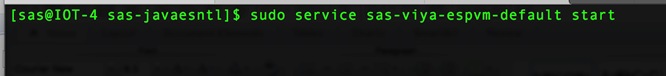
3. After you have started the service, you can access SAS Event Stream Processing Studio using a web browser that is running on Windows or Linux. Open SAS Event Stream Processing Studio from a URL with the following format:
http://172.16.21.25:18080/SASEventStreamProcessingStudio
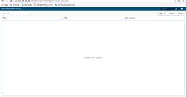
![]() Note: For esp-studio-hostname and port, specify values that are appropriate for your deployment. The default port is 8080.
Note: For esp-studio-hostname and port, specify values that are appropriate for your deployment. The default port is 8080.
4. Before you can open or create a model in SAS Event Stream Processing Studio, you must start the XML factory server. Change directories to the following location:
cd /opt/sas/viya/home/SASEventStreamProcessingEngine/4.2.0/bin
5. Run the following command:
dfesp_xml_server -pubsub n -http-admin adminport -http-pubsub pubsubport &
The -pubsub argument specifies a port for publish and subscribe actions. Replace n with the appropriate port number.
The -http-admin argument runs the XML server as a factory server that supports the creation of projects. For adminport, specify the port that you want to use for HTTP administration requests.
The ampersand (&) enables additional commands to be entered in the same window that started the server.
![]() Note: If you have a project that is predefined, use the -model argument to run the project as a stand-alone engine.
Note: If you have a project that is predefined, use the -model argument to run the project as a stand-alone engine.
The -http-pubsub argument sets up a publish/subscribe HTTP server that uses the specified port pubsubport. For more information about the XML server, see SAS® Event Stream Processing: Using the XML Layer.
6. To create the default directory for storing projects that you create or import in SAS Event Stream Processing Studio and to set the permissions, run the following commands:
sudo mkdir -p /opt/sas/viya/config/data/espvm/esp_projects sudo chown sas:sas /opt/sas/viya/config/data/espvm/esp_projects sudo chmod g+w /opt/sas/viya/config/data/espvm/esp_projects
7. (Optional) To check the status of SAS Event Stream Processing Studio, run the following command:
sudo service sas-viya-espvm-default status
View Deployment Logs
To view the logs of your yum deployment, run the following commands:
sudo yum history
sudo less /var/log/yum.log
Setting Up Streamviewer
Overview
Streamviewer provides a user interface that enables you to subscribe to window event streams from one or more event stream processing engines, and display the events that stream through it. You can display each event as a row in a table or as an element of a graph. Each table row is keyed by the schema key of the corresponding window. You can save and load a collection of tables, graphs, and their customized settings in dashboards.
Streamviewer dashboards are stored in a configuration database. For the configuration database storage mechanism, you can use one of several supported enterprise databases or the stand-alone, file-based RDBMS SQLite database that is provided with SAS Event Stream Processing. After you have configured your storage mechanism, you can run the Streamviewer user interface from either a local or from a remote SAS Event Stream Processing installation.
It is recommended that you run Streamviewer from a remote installation using SQLite as the storage mechanism. This helps you avoid browser limitations on local file access. It also makes it easier for more than one user to access Streamviewer at a time.
![]() Note: The following instructions assume that you have already set the environment variables DFESP_HOME and LD_LIBRARY_PATH.
Note: The following instructions assume that you have already set the environment variables DFESP_HOME and LD_LIBRARY_PATH.
Setting Up the Configuration Database
Streamviewer requires a relational database to persistently store configuration information. You can use SQLite, which is provided with the product. Alternatively, you can use an enterprise database management system.
Setting Up SQLite as the Storage Mechanism
SAS Event Stream Processing includes an empty SQLite database and a script named sqlite_run.sh to run a SQLite-based event stream processing configuration server.
To run the Streamviewer configuration server using SQLite as its persistent storage mechanism, complete the following steps:
1. Create a directory for your configuration server: SVCONF_DIR.
2. Change your current directory to SVCONF_DIR. Here is an example of a valid location for this directory:
cd /opt/sas/viya/config/SVCONF_DIR
3. Copy the database configuration files from the SAS Event Stream Processing installation streamviewer directory to SVCONF_DIR:
cp $DFESP_HOME/share/tools/streamviewer/db/sqlite_run.sh . chmod +x ./sqlite_run.sh
cp $DFESP_HOME/share/tools/streamviewer/db/streamviewer.db .
4. Run the SQLite script.
cd /opt/sas/viya/config/SVCONF_DIR
nohup SQLite_run.sh -p http_sql_port -d database_file &
5. Replace http_sql_port with an available port number.
The -d database_file option uses streamviewer.db as the default. You can use this option to run the configuration server using a database file other than streamviewer.db. This option enables you to keep any number of Streamviewer databases and use different database files to organize your dashboard collections. The ampersand (&) causes the script to run in the background, enabling you to return to the command prompt while the script is running. Include the nohup command to enable SQLite to continue running when the shell window is closed.
For more information about SQLite, visit https://www.sqlite.org/.
While you have used the default SQLite database, note that the following enterprise databases are supported for Streamviewer:
· MySQL
· Oracle Database
· PostgreSQL
· Microsoft SQL Server
· Sybase (SAP)
· IBM DB2
Testing the Server-Database Connection
Test your server and database connectivity:
$DFESP_HOME/bin/dfesp_xml_client -url "http://[host:port]/tables/streamviewer"
Where host is the XML server location and port is the SQL port that is specified in your server settings.
The output from running dfesp_xml_client should look like the following:
<tables>
<table name='streamviewer_chart'/>
<table name='streamviewer_dashboard'/>
<table name='streamviewer_server'/>
</tables>
Running Streamviewer on a Web Server
To run Streamviewer with SAS Event Stream Processing installed in a remote location, use a web server. If a web server is available, you can deploy Streamviewer to that server for use. We use Apache Tomcat, an open- source web server application, to configure and use Streamviewer as a web application.
Installing and Configuring Apache Tomcat for Streamviewer Use
![]() Note: If you have set up a web server, go to Installing Streamviewer in an Apache Tomcat Instance.
Note: If you have set up a web server, go to Installing Streamviewer in an Apache Tomcat Instance.
To install Apache Tomcat for Streamviewer use, download Apache Tomcat. You can find Tomcat binary distributions at http://tomcat.apache.org/. Follow the instructions provided at that website to install Apache Tomcat.
![]() Note: Obtain an updated version of Java SE Development Kit. You can find this at http://www.oracle.com/ technetwork/java/javase/downloads. The Apache Tomcat web page http://tomcat.apache.org/whichversion.html provides the requirements for each version of Tomcat.
Note: Obtain an updated version of Java SE Development Kit. You can find this at http://www.oracle.com/ technetwork/java/javase/downloads. The Apache Tomcat web page http://tomcat.apache.org/whichversion.html provides the requirements for each version of Tomcat.
Installing Streamviewer in an Apache Tomcat Instance
To install Streamviewer under an Apache Tomcat instance, copy the streamviewer directory from $DFESP_HOME/share/tools into the Apache Tomcat webapps directory. Rename the Apache Tomcat installation root to TOMCAT_HOME.
On Linux, run the following:
export TOMCAT_HOME=/path/apache-tomcat-X.x.x
cp -r $DFESP_HOME/share/tools/streamviewer $TOMCAT_HOME/webapps/
If your Apache Tomcat is running on host tomcat_host and port tomcat_port, open a web browser and navigate to http://tomcat_host:tomcat_port/streamviewer.
http://172.16.21.25:8080/streamviewer
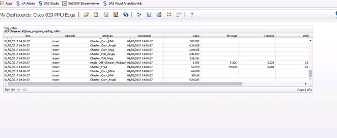
Connecting to the Configuration Server
![]() Operations from the Streamviewer dashboard.
Operations from the Streamviewer dashboard.
To connect to the configuration server, complete the following steps:
1. After Streamviewer is running, connect to the event stream processing configuration server that you have started. In the ESP Model Viewer window, enter your server information in the Configuration field. This is the information provided by your server location and the SQL port that you specified earlier.
![]()
![]() Note: Specify the URI that reflects the protocol that your configuration server is using. For example, when you have a remote UNIX server hostname with an SQL port port, enter http://hostname:port or https:// hostname:port.
Note: Specify the URI that reflects the protocol that your configuration server is using. For example, when you have a remote UNIX server hostname with an SQL port port, enter http://hostname:port or https:// hostname:port.
2. Click Load. My Dashboards appears in the Datasource field. You should see any data sources that you have defined in your odbc.ini file used by the configuration server.
Connecting to Event Stream Processing Servers in Streamviewer
Streamviewer enables you to view event streaming models from more than one event stream processing server at a time. After you have specified the configuration server information and have loaded or created a dashboard, you can select running servers to publish models and events into your dashboard.
To connect to a server in Streamviewer, complete the following steps:
1. Click the Manage Servers button to select an HTTP Publish/Subscribe server. You can click New to enter your ESP server location for Host and your HTTP Publish/Subscribe port for Port.
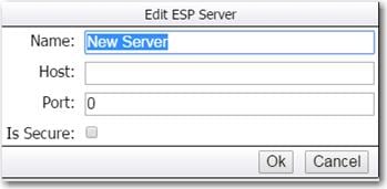
2. All the server locations that you have created appear in the ESP Servers window. Select a server from the list and click Done. You now can build and save dashboards in Streamviewer using the servers that you selected in the ESP Servers window, and the configuration server that you specified in the ESP Model Viewer window.
Post-Installation Configuration
Directory Structure and Permissions
After you install SAS Event Stream Processing, the files for the engine and the authentication package are located in the following directory:
/opt/sas/viya/home/SASEventStreamProcessingEngine/4.2.0
The project files that you create are saved in the following directory: /opt/sas/viya/config/data/espvm/ esp_projects. (For example : this created for PMU project, which will be used for all projects )
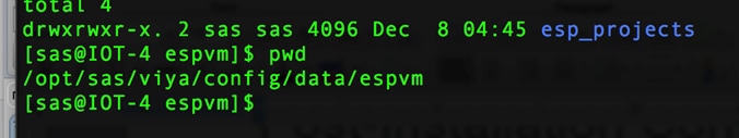
This directory must be created before you import projects from a previous version of SAS Event Stream Processing or create projects with SAS Event Stream Processing Studio. For more information, see section Start SAS Event Stream Processing Studio. Be aware that imported projects are not automatically migrated to the required format to run with SAS Event Stream Processing 4.2. For more information about upgrading from a previous version, see SAS® Event Stream Processing 4.2: What's New.
Configuration files for adapters and logs are located in the following directory:
/opt/sas/viya/home/SASEventStreamProcessingEngine/4.2.0/etc
The basic directory path enables write access per user group, and it is owned by the sas user. To grant permission to users to edit the configuration files, the administrator must add them to the sas group.
Membership in this group also enables a user to create a projects directory that is required to use SAS Event Stream Processing Studio. For more information, see section User Accounts.
Later, if you update your deployment, the configuration files are not altered.
For more information about log settings and modification of the log configuration file, see section Configure Logging.
Change the Default Port (Optional)
You can change the port settings for SAS Event Stream Processing Studio. The default port, 8080, is appropriate for most environments. To change the default port, complete the following steps:
1. Use your preferred text editor to open the following file for modification:
sudo /opt/sas/viya/home/bin/sas-espvm
2. Locate the following line in the file:
export java_option_server_port="-Dserver.port=8080"
3. Change the default port, 8080, to the appropriate port.
4. Save and close the file.
5. Restart the espvm service:
sudo service sas-viya-espvm-default stop sudo service sas-viya-espvm-default start
Configure Logging (optional)
The SAS Event Stream Processing Engine writes event information to a log file in the following location:
/opt/sas/viya/home/SASEventStreamProcessingEngine/4.2.0/etc/esp-logger.xml
By default, the logging level is INFO, and event information is sent to standard output.
You can configure the esp-logger.xml file by enabling (removing comment tags) or disabling (adding comment tags) specific log settings in the configuration section of the file.
![]() Note: In this case, you are outputting the log information to the terminal.
Note: In this case, you are outputting the log information to the terminal.
For example, to prevent logging from being displayed on the local terminal screen (standard output), comment out the following section in the esp-logger.xml file:
<!--
<appender class="ConsoleAppender" name="consoleAppender">
<param name="ImmediateFlush" value="true"/>
<layout>
<param name="ConversionPattern" value="%d; %-5p; %t; %c; (%F:%L); %m"/>
</layout>
</appender>
-->
As another example, log rollover is disabled (commented out) by default. To enable log rollover, uncomment the following lines in the esp-logger.xml file:
<appender class="RollingFileAppender" name="timeBasedRollingFileAppender">
<param name="Append" value="true"/>
<param name="ImmediateFlush" value="true"/>
<rollingPolicy class="TimeBasedRollingPolicy">
<param name="fileNamePattern" value="%S{OSENV.DFESP_HOME}/ log/esp-%S{jobid}-%d{yyyy-MM-dd}.log" />
</rollingPolicy>
<layout>
<param name="HeaderPattern"
value="Host: '%S{hostname}', Process: '%S{pid}', OS: '%S{os_bits} %S{os_family}', OS Release: '%S{os_release}'"/>
<param name="ConversionPattern" value="%d; %-5p; %t; %c; (%F:%L); %m"/>
</layout>
</appender>
The SAS Event Stream Processing Engine produces a new log file at midnight each day. The date stamp is applied to the filename in the format PID-yyyy-MM-dd, and each file is saved in the same directory as the esp-logger.xml configuration file. The PID is an auto-generated process identifier. The following is an example of a filename:
/var/log/sas/viya/esp/esp-PID-2016-08-25
Restart the server to apply the changes to the esp-logger.xml file. If you do not change any log settings, SAS Event Stream Processing behavior is the same as it has been in previous releases. For more information about logging, see SAS Event Stream Processing: Troubleshooting.
Validating the Deployment
Verify RPM Packages
Your SAS software was delivered in RPM (Red Hat Package Manager) packages. Use this basic command to verify an RPM package:
rpm -Vv package-name
For example, to verify the contents of the sas-esp package, run the following command:
rpm -Vv sas-esp
You can also create a for loop command for verifying multiple packages that share a common naming convention. For example, to verify all packages whose names begin with sas-, use the following query:
for i in $(rpm -qa | grep -e "^sas-");do rpm -Vv $i;done
A successful verification shows the list of files that make up the RPM and with no error indicators, as follows:
# rpm -Vv sas-esp
......... /opt/sas/viya/home/lib/esp/sas-init-functions
An unsuccessful verification provides error indicators that are next to the filename. Here is an example:
# rpm -Vv sas-esp
package sas-esp is not installed
The error indicators are shown in the following format:
SM5DLUGT c
In addition, if a file is missing, the error message contains the word "missing":
missing /opt/sas/viya/home/lib/esp/sas-init-functions
Error Indicators
RPM verification produces various error indicators. Some of them are innocuous. For example, if you set up a data source connection as instructed in Enable Database Connectivity on page 20, some error indicators might appear for the files that you updated.
You might see the following error indicators when you perform RPM verification:
S - file size
RPM keeps track of file sizes. A difference of even one byte triggers a verification error.
M - file mode
The permissions mode specifies access for the file's owner, group members, and others. Two additional bits determine whether a user's group or user ID should be changed if they execute the program that is contained in the file. These bits permit any user to become root for the duration of the program.
5 - MD5 checksum
The MD5 checksum of a file is a 128-bit number that is mathematically derived from the contents of the file. The MD5 checksum conveys no information about the contents of the original file, but any change to the file results in a change to the checksum. RPM creates MD5 checksums for all files that it manipulates and stores them in its database. If one of these files is changed, the checksum changes and the change is detected by RPM.
D - major and minor numbers
Device character and block files contain a major number. The major number is used to communicate information to the device driver that is associated with the special file. For example, under Linux, the special files for SCSI disk drives should have a major number of 8. The major number for an IDE disk drive's special file should be 3.
CAUTION! Any change to a file's major number could produce unwanted results. RPM tracks these changes.
A file's minor number is similar to the major number, but conveys different information to the device driver. For disk drives, this information can consist of a unit identifier.
L - symbolic link
If a file is a symbolic link, RPM checks the text string that contains the name of the symbolically linked file.
U - file owner
Most operating systems keep track of each file's creator, primarily for resource accounting. Linux and UNIX also use file ownership to help determine access rights to the file. In addition, some files, when executed by a user, can temporarily change the user's ID, normally to a more privileged ID. Therefore, any change of file ownership might have significant effects on data security and system availability.
G - file group
Similar to file ownership, a group specification is attached to each file. Primarily used for determining access rights, a file's group specification can also become a user's group ID if that user executes the file's contents. Therefore, any changes in a file's group specification are important and should be monitored.
M - modification time
Most operating systems keep track of the date and time that a file was last modified. RPM keeps modification times in its database.
c - configuration file
Useful for quickly identifying the specified configuration file.
To configure the ESP Server to connect to the LASR Analytic Server broker, log in to each server where ESP Server is installed and run the following commands:
cd /home/sas
Create a file “start_lasr_adapter.sh” with the following contents:
vi start_lasr_adapter.sh
export DFESP_HOME=/opt/sas/viya/home/SASEventStreamProcessingEngine/4.2.0
export LD_LIBRARY_PATH=${DFESP_HOME}/lib:${DFESP_HOME}/lib/tk:/opt/sas/viya/home/SASFoundation/sasexe:/home/sas/tools:/home/sas/tools/cyrus-sasl/2.1.26/lib
export PATH=$DFESP_HOME/bin:$PATH
echo $DFESP_HOME
$DFESP_HOME/bin/dfesp_lasr_adapter -k sub -h "dfESP://<ESP Server node>:13261/pmu_proj/pmu_cq/PMU_edge_data_in?snapshot=true" -H <zookeeper node>:10011 -t HPS.pmu_edge_data_in -X $DFESP_HOME/bin/tklasrkey.sh -n -A 10
Execute the script:
./home/sas/start_lasr_adapter.sh
Create the Kafka Topic
To create the Kafka topic, log into the server where the Kafka broker is installed and run the following commands (RHEL1 is used in the example below):
cd /opt/cloudera/parcels/KAFKA-2.0.2-1.2.0.2.p0.5/bin
Create a topic called PMU:
./kafka-topics --create --zookeeper localhost:2181 --replication-factor 1 --partition 1 --topic PMU
![]()
Check to see the topic was created successfully run the following command:
./kafka-topics --list --zookeeper localhost:2181
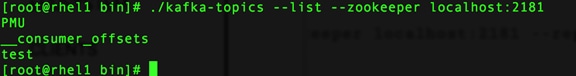
Configure ESP Server to Connect to Kafka Broker
To configure the ESP Server to connect to the Kafka broker, log in to each server where ESP Server is installed and run the following commands:
cd /home/sas
Create a file “start_kafka_adapter.sh” with the following contents:
vi start_kafka_adapter.sh
export DFESP_HOME=/opt/sas/viya/home/SASEventStreamProcessingEngine/4.2.0
export LD_LIBRARY_PATH=${DFESP_HOME}/lib:${DFESP_HOME}/lib/tk:/opt/sas/viya/home/SASFoundation/sasexe:/home/sas/tools:/home/sas/tools/cyrus-sasl/2.1.26/lib
export PATH=$DFESP_HOME/bin:$PATH
echo $DFESP_HOME
$DFESP_HOME/bin/dfesp_kafka_adapter -k sub -h "dfESP://<ESP Client Node>:61002/pmu_proj/pmu_cq/Tag_ctllim?snapshot=false" -t PMU -z csv -s <Kafka Broker>:9092 -p 0 -o solace03.unx.sas.com:33333 -d "%Y-%m-%d %H:%M:%S" -n 10
Execute the script:
./home/sas/start_kafka_adapter.sh
Two items need to be installed on the Cisco IR829G router; the SAS Event Stream Processing (ESP) client software and the model used to filter and analyze the incoming data. The ESP client software needs to be installed only once (not counting upgrades). Any number of models can be installed, and re-installed as the model is refined or changed.
The ESP Client software is installed as an IOx application. Broadly, IOx applications can be categorized as below:
· PaaS style apps: These applications are more portable, typically developed using dynamic languages such as Java, Ruby, Python etc, and are designed to run in specific PaaS frameworks.
· Container apps: These apps are comprised of application code, 3rd party dependent libraries, native binaries (and entire root file system, minus the kernel) packaged into one archive.
· Docker style apps: These applications are similar to LXC/Container style applications. The only difference is at the time of application development, where the developer can use docker tooling to generate their root file system.
· VM packaged apps: These are applications packaged as virtual machines. It contains complete OS (kernel + root file system), libraries, and application code packaged into one package.
For this project, container apps are used. The instructions below describe how to install both the ESP client software and the model required to run.
Uploading the Edge Application
Cisco Fog Director is used to manage the software on the routers. First, upload the application into Cisco Fog Director; this enables the application for use then install the application on the routers. To upload the Edge application, complete the following steps:
1. Log into Fog Director.
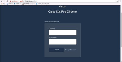
2. Click the tab APPS and click Add New App.
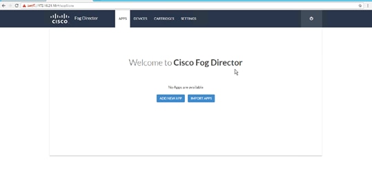
3. Choose Upload from my computer
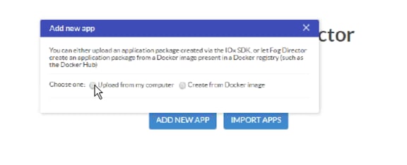
4. Navigate to the file to install and click Open. For this project, install: EAS-ESP-ir800-lec.tar. For a similar ESP client and model bundle, contact your SAS representative.
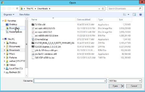
5. After the installation completes, the application is displayed as shown below.
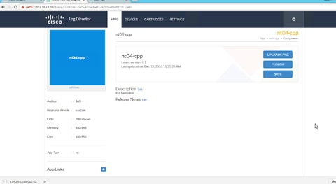
Installing the Edge Application
The next step is to install the uploaded application on the routers. To install the Edge application, complete the following steps:
1. Continuing from the steps above (or log into Cisco Fog Director and click the Apps tab), select the application to be published
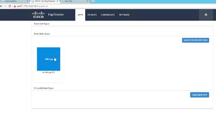
2. A window with application details displays. Click Install.
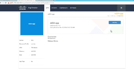
3. Select the routers you want to install the application on. In this example, we are installing onto two routers.
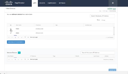
4. After choosing which routers, click Add Selected Devices. The selected devices appear in the bottom portion of the screen.
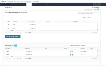
5. Click Next.
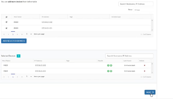
6. The screen below appears. Each device (router) to install is represented as a small blue square in the lower portion of the window.
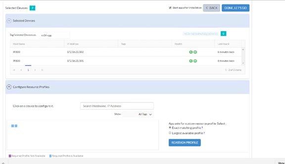
7. You need to change the network to iox-bridge0 for each device. This only needs to be once per device (for example, the next time you install a model on these devices this step will not be necessary). Click each blue square. A Preferred networks section will appear. From the network drop-down menu, choose 'iox-bridge0' and click Reassign Networks.
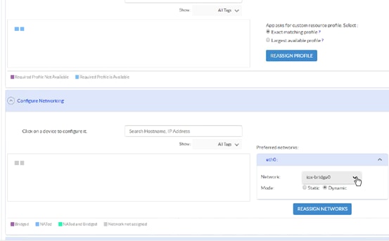
8. Cisco Fog Director connects to the devices, displaying the screen below. Click Done, Let's Go.
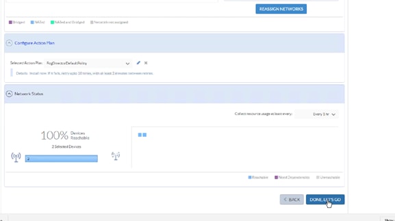
9. The application installs.
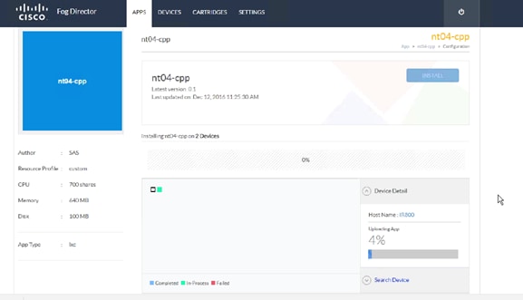
10. A status screen appears after installation is complete.
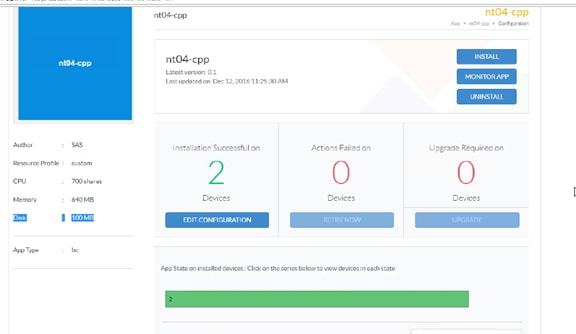
Verifying Application Deployment
To verify the application was deployed, you can log into the router and inspect the running processes. To do this you need to log into the router via secure shell. Before you can do that we have to create the ssh keys. To verify, complete the following steps:
1. To enable ssh on the router, first telnet into the Cisco IR829G using it's IP address (example shows 176.16.21.101). Use cisco/cisco as username/password.
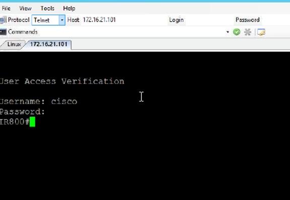
2. Generate the keys by issuing the commands shown below.
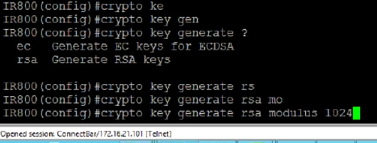
3. Exit the session and re-login via ssh.
4. When logged in via ssh, you need to navigate to the host operating system. Run the following command:
172.16.21.101 2070
5. This opens a session on the host (on port 2070). Enter the username: root. There is no password.
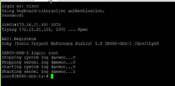
6. To see the running process, run the command: top
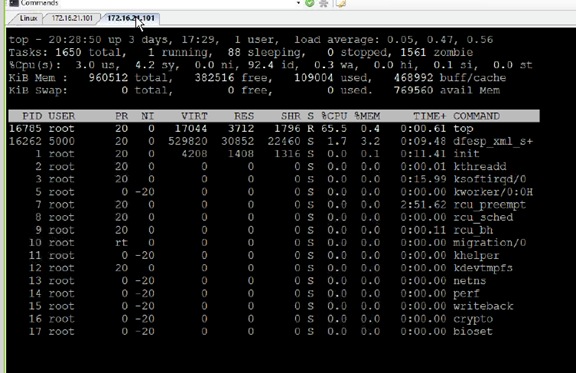
7. "dfesp_xml" is the name of the ESP client process.
This section provides the bill of materials for this solution. The tables below detail the BOM for each logical set of components, categorized as follows:
· Fabric Interconnect
· Cisco ACI
· Hadoop + LASR nodes
· SAS Visual Analytics / Visual Statistics nodes
· SAS Event Stream Processing Server nodes
· Kafka nodes
· Fog Director nodes
· Cisco IR829G routers
· Cisco Firewall Security Appliances
· Redhat Enterprise Linux software
· Cloudera software
· SAS Advanced Analytics software
Table 8 Bill of Materials for Cisco UCS Fabric Interconnect 6332 – Data Center
| Part Number |
Description |
Quantity |
| (Not sold standalone) UCS 6332 1RU FI/No PSU/32 QSFP+ |
2 |
|
| UCS-PSU-6332-AC |
UCS 6332 Power Supply/100-240VAC |
4 |
| CAB-9K12A-NA |
Power Cord, 125VAC 13A NEMA 5-15 Plug, North America |
4 |
| QSFP-H40G-CU3M |
40GBASE-CR4 Passive Copper Cable, 3m |
8 |
| QSFP-H40G-CU3M |
40GBASE-CR4 Passive Copper Cable, 3m |
48 |
| UCS-LIC-6300-40GC |
3rd Gen FI Per port License to connect C-direct only |
48 |
| QSFP-40G-SR-BD |
QSFP40G BiDi Short-reach Transceiver |
8 |
| N10-MGT014 |
UCS Manager v3.1 |
2 |
| UCS-FAN-6332 |
UCS 6332 Fan Module |
8 |
| UCS-ACC-6332 |
UCS 6332 Chassis Accessory Kit |
2 |
Table 9 Bill of Materials for Cisco ACI
| Part Number |
Description |
Quantity |
| N9K-C9508-B2 |
Nexus 9508 Chassis Bundle with 1 Sup, 3 PS, 2 SC, 6 FM, 3 FT |
2 |
| N9K-C9332PQ |
Nexus 9300 with 32p 40G QSFP+ |
2 |
| N9K-C9372PX |
Nexus 9300 with 48p 10G SFP+ and 6p 40G QSFP+ |
1 |
| N9K-X9736PQ |
Spine Line-Card |
2 |
| APIC-M1 |
APIC Appliance |
3 |
| N9K POWERCABLES |
Power Cables |
3 |
| CAB-C13-C14-AC |
Power cord, C13 to C14 (recessed receptacle), 10A |
4 |
| QSFP-H40G-CU3M |
40GBASE-CR4 Passive Copper Cable, 3m |
24 |
| Nexus 9372TX |
Nx-OS mode switch for out of band Management |
1 |
| N9K-C9500-RMK |
Nexus 9500 Rack Mount Kit |
2 |
| CAB-C19-CBN |
Cabinet Jumper Power Cord, 250 VAC 16A, C20-C19 Connectors |
6 |
| N9K-C9500-LC-CV |
Nexus 9500 Linecard slot cover |
16 |
| N9K-C9500-SUP-CV |
Nexus 9500 Supervisor slot cover |
2 |
| N9K-PAC-3000W-B |
Nexus 9500 3000W AC PS, Port-side Intake |
6 |
| N9K-SUP-A |
Supervisor for Nexus 9500 |
2 |
| N9K-SC-A |
System Controller for Nexus 9500 |
4 |
| N9K FABRIC |
Fabric Module |
2 |
| N9300 RACK |
Rack Mount Kit |
3 |
| N9K-C9300-RMK |
Nexus 9300 Rack Mount Kit |
3 |
Table 10 Bill of Materials for Hadoop and SAS LASR nodes
| Part Number |
Description |
Quantity |
| UCSC-C240-M4SX |
UCS C240 M4 SFF 24 HD w/o CPU, mem, HD, PCIe, PS, railkt w/expndr |
19 |
| CON-OSP-C240M4SX |
SNTC-24X7X4OS UCS C240 M4 SFF 24 HD w/o CPU, mem |
19 |
| UCS-CPU-E52690E |
2.60 GHz E5-2690 v4/135W 14C/35MB Cache/DDR4 2400MHz |
38 |
| UCS-ML-1X324RV-A |
32GB DDR4-2400-MHz LRDIMM/PC4-19200/quad rank/x4/1.2v |
304 |
| UCS-SD240GBKS4-EB |
240 GB 2.5 inch Enterprise Value 6G SATA SSD (boot) |
38 |
| UCSC-RAILB-M4 |
Ball Bearing Rail Kit for C220 M4 and C240 M4 rack servers |
19 |
| UCSC-MLOM-C40Q-03 |
Cisco VIC 1387 Dual Port 40Gb QSFP CNA MLOM |
19 |
| UCSC-PSU2V2-1200W |
1200W / 800W V2 AC Power Supply for 2U C-Series Servers |
38 |
| CAB-9K12A-NA |
Power Cord, 125VAC 13A NEMA 5-15 Plug, North America |
38 |
| UCSC-PCI-1C-240M4 |
Right PCI Riser Bd (Riser 1) 2onbd SATA bootdrvs+ 2PCI slts |
19 |
| UCS-SD16TBKS4-EV |
1.6TB 2.5 inch Enterprise Value 6G SATA SSD |
152 |
| UCS-M4-V4-LBL |
Cisco M4 - v4 CPU asset tab ID label (Auto-Expand) |
19 |
| N20-BBLKD |
UCS 2.5 inch HDD blanking panel |
304 |
| UCSC-HS-C240M4 |
Heat sink for UCS C240 M4 rack servers |
38 |
| UCSC-SAS12GHBA |
Cisco 12Gbps Modular (non-RAID) SAS HBA |
19 |
| C1UCS-OPT-OUT |
Cisco ONE Data Center Compute Opt Out Option |
19 |
Table 11 Bill of Materials for SAS Visual Analytics / Visual Server nodes
| Part Number |
Description |
Quantity |
| UCSC-C240-M4SX |
UCS C240 M4 SFF 24 HD w/o CPU, mem, HD, PCIe, PS, railkt w/expndr |
3 |
| CON-OSP-C240M4SX |
SNTC-24X7X4OS UCS C240 M4 SFF 24 HD w/o CPU, mem |
3 |
| UCS-CPU-E52690E |
2.60 GHz E5-2690 v4/135W 14C/35MB Cache/DDR4 2400MHz |
6 |
| UCS-ML-1X324RV-A |
32GB DDR4-2400-MHz LRDIMM/PC4-19200/quad rank/x4/1.2v |
12 |
| UCS-SD240GBKS4-EB |
240 GB 2.5 inch Enterprise Value 6G SATA SSD (boot) |
6 |
| UCSC-RAILB-M4 |
Ball Bearing Rail Kit for C220 M4 and C240 M4 rack servers |
3 |
| UCSC-MLOM-C40Q-03 |
Cisco VIC 1387 Dual Port 40Gb QSFP CNA MLOM |
3 |
| UCSC-PSU2V2-1200W |
1200W / 800W V2 AC Power Supply for 2U C-Series Servers |
6 |
| CAB-9K12A-NA |
Power Cord, 125VAC 13A NEMA 5-15 Plug, North America |
6 |
| UCSC-PCI-1C-240M4 |
Right PCI Riser Bd (Riser 1) 2onbd SATA bootdrvs+ 2PCI slts |
3 |
| UCS-SD16TBKS4-EV |
1.6TB 2.5 inch Enterprise Value 6G SATA SSD |
24 |
| UCS-M4-V4-LBL |
Cisco M4 - v4 CPU asset tab ID label (Auto-Expand) |
3 |
| N20-BBLKD |
UCS 2.5 inch HDD blanking panel |
48 |
| UCSC-HS-C240M4 |
Heat sink for UCS C240 M4 rack servers |
6 |
| UCSC-SAS12GHBA |
Cisco 12Gbps Modular (non-RAID) SAS HBA |
3 |
| C1UCS-OPT-OUT |
Cisco ONE Data Center Compute Opt Out Option |
3 |
Table 12 Bill of Materials for SAS Event Stream Processing Server nodes
| Part Number |
Description |
Quantity |
| UCSC-C240-M4SX |
UCS C240 M4 SFF 24 HD w/o CPU, mem, HD, PCIe, PS, railkt w/expndr |
2 |
| CON-OSP-C240M4SX |
SNTC-24X7X4OS UCS C240 M4 SFF 24 HD w/o CPU, mem |
2 |
| UCS-CPU-E52690E |
2.60 GHz E5-2690 v4/135W 14C/35MB Cache/DDR4 2400MHz |
4 |
| UCS-ML-1X324RV-A |
32GB DDR4-2400-MHz LRDIMM/PC4-19200/quad rank/x4/1.2v |
8 |
| UCS-SD240GBKS4-EB |
240 GB 2.5 inch Enterprise Value 6G SATA SSD (boot) |
4 |
| UCSC-RAILB-M4 |
Ball Bearing Rail Kit for C220 M4 and C240 M4 rack servers |
2 |
| UCSC-MLOM-C40Q-03 |
Cisco VIC 1387 Dual Port 40Gb QSFP CNA MLOM |
2 |
| UCSC-PSU2V2-1200W |
1200W / 800W V2 AC Power Supply for 2U C-Series Servers |
4 |
| CAB-9K12A-NA |
Power Cord, 125VAC 13A NEMA 5-15 Plug, North America |
4 |
| UCSC-PCI-1C-240M4 |
Right PCI Riser Bd (Riser 1) 2onbd SATA bootdrvs+ 2PCI slts |
2 |
| UCS-SD16TBKS4-EV |
1.6TB 2.5 inch Enterprise Value 6G SATA SSD |
16 |
| UCS-M4-V4-LBL |
Cisco M4 - v4 CPU asset tab ID label (Auto-Expand) |
2 |
| N20-BBLKD |
UCS 2.5 inch HDD blanking panel |
32 |
| UCSC-HS-C240M4 |
Heat sink for UCS C240 M4 rack servers |
4 |
| UCSC-SAS12GHBA |
Cisco 12Gbps Modular (non-RAID) SAS HBA |
2 |
| C1UCS-OPT-OUT |
Cisco ONE Data Center Compute Opt Out Option |
2 |
Table 13 Bill of Materials for Cisco UCS Fabric Interconnect 6332 – Transfer Layer
| Part Number |
Description |
Quantity |
| UCS-SP-FI6332 |
(Not sold standalone) UCS 6332 1RU FI/No PSU/32 QSFP+ |
2 |
| UCS-PSU-6332-AC |
UCS 6332 Power Supply/100-240VAC |
4 |
| CAB-9K12A-NA |
Power Cord, 125VAC 13A NEMA 5-15 Plug, North America |
4 |
| QSFP-H40G-CU3M |
40GBASE-CR4 Passive Copper Cable, 3m |
8 |
| QSFP-H40G-CU3M |
40GBASE-CR4 Passive Copper Cable, 3m |
8 |
| UCS-LIC-6300-40GC |
3rd Gen FI Per port License to connect C-direct only |
8 |
| QSFP-40G-SR-BD |
QSFP40G BiDi Short-reach Transceiver |
8 |
| N10-MGT014 |
UCS Manager v3.1 |
2 |
| UCS-FAN-6332 |
UCS 6332 Fan Module |
8 |
| UCS-ACC-6332 |
UCS 6332 Chassis Accessory Kit |
2 |
Table 14 Bill of Materials for Kafka nodes
| Part Number |
Description |
Quantity |
| UCSC-C240-M4SX |
UCS C240 M4 SFF 24 HD w/o CPU, mem, HD, PCIe, PS, railkt w/expndr |
4 |
| CON-OSP-C240M4SX |
SNTC-24X7X4OS UCS C240 M4 SFF 24 HD w/o CPU, mem |
4 |
| UCS-CPU-E52690E |
2.60 GHz E5-2690 v4/135W 14C/35MB Cache/DDR4 2400MHz |
8 |
| UCS-ML-1X324RV-A |
32GB DDR4-2400-MHz LRDIMM/PC4-19200/quad rank/x4/1.2v |
16 |
| UCS-SD240GBKS4-EB |
240 GB 2.5 inch Enterprise Value 6G SATA SSD (boot) |
8 |
| UCSC-RAILB-M4 |
Ball Bearing Rail Kit for C220 M4 and C240 M4 rack servers |
4 |
| UCSC-MLOM-C40Q-03 |
Cisco VIC 1387 Dual Port 40Gb QSFP CNA MLOM |
4 |
| UCSC-PSU2V2-1200W |
1200W / 800W V2 AC Power Supply for 2U C-Series Servers |
8 |
| CAB-9K12A-NA |
Power Cord, 125VAC 13A NEMA 5-15 Plug, North America |
8 |
| UCSC-PCI-1C-240M4 |
Right PCI Riser Bd (Riser 1) 2onbd SATA bootdrvs+ 2PCI slts |
4 |
| UCS-SD16TBKS4-EV |
1.6TB 2.5 inch Enterprise Value 6G SATA SSD |
32 |
| UCS-M4-V4-LBL |
Cisco M4 - v4 CPU asset tab ID label (Auto-Expand) |
4 |
| N20-BBLKD |
UCS 2.5 inch HDD blanking panel |
64 |
| UCSC-HS-C240M4 |
Heat sink for UCS C240 M4 rack servers |
8 |
| UCSC-SAS12GHBA |
Cisco 12Gbps Modular (non-RAID) SAS HBA |
4 |
| C1UCS-OPT-OUT |
Cisco ONE Data Center Compute Opt Out Option |
4 |
Table 15 Bill of Materials for Cisco Fog Director nodes
| Part Number |
Description |
Quantity |
| UCSC-C220-M4S |
UCS C220 M4 SFF w/o CPU, mem, HD, PCIe, PSU, rail kit |
1 |
| CON-OSP-C220M4S |
SNTC-24X7X4OS UCS C220 M4 SFF w/o CPU, mem, HD |
1 |
| UCS-CPU-E52690E |
2.60 GHz E5-2690 v4/135W 14C/35MB Cache/DDR4 2400MHz |
2 |
| UCS-ML-1X324RV-A |
32GB DDR4-2400-MHz LRDIMM/PC4-19200/quad rank/x4/1.2v |
8 |
| UCS-HD12TB10K12G |
1.2 TB 12G SAS 10K RPM SFF HDD |
8 |
| UCSC-MLOM-C40Q-03 |
Cisco VIC 1387 Dual Port 40Gb QSFP CNA MLOM |
1 |
| UCSC-RAILB-M4 |
Ball Bearing Rail Kit for C220 M4 and C240 M4 rack servers |
1 |
| UCSC-PSUV2-1050DC |
1050W V2 -48 VDC Power Supply for C220M4/S3260 |
2 |
| CAB-48DC-40A-8AWG |
C-Series -48VDC PSU Power Cord, 3.5M, 3 Wire, 8AWG, 40A |
2 |
| UCSC-HS-C220M4 |
Heat sink for UCS C220 M4 rack servers |
2 |
| UCSC-SCCBL220 |
Supercap cable 950mm |
1 |
| UCS-M4-V4-LBL |
Cisco M4 - v4 CPU asset tab ID label (Auto-Expand) |
1 |
| UCSC-MRAID12G |
Cisco 12G SAS Modular Raid Controller |
1 |
| UCSC-MRAID12G-2GB |
Cisco 12Gbps SAS 2GB FBWC Cache module (Raid 0/1/5/6) |
1 |
| C1UCS-OPT-OUT |
Cisco ONE Data Center Compute Opt Out Option |
1 |
| IOX-SOFTWARE |
OX Core SW with Fog Director |
1 |
Table 16 Bill of Materials for Cisco 829 Industrial Integrated Services Routers
| Part Number |
Description |
| IR829GW-LTE-XX-AK9* |
829 Industrial ISR, 4G/LTE multimode, 802.11n FCC |
| CON-SNT-IR82XXAK |
NTC-8X5XNBD 829 Industrial ISR, 4G/LTE multimode Ve |
| SWAP1530-81-A1-K9 |
Cisco AP1530 Series Unified WiFi 8.1 Software Release |
| SL-IR800-IPB-K9 |
P Base License for Cisco IR800 series routers IOX PIDs |
| SWAP1530-81A-A1-K9 |
Cisco AP1530 Series Autonomous WiFi 8.1 Software Release |
| SL-IR800-DATA-K9 |
Data License for Cisco IR800 series routers IOX PIDs |
| SL-IR800-SEC-K9 |
Security License for Cisco IR800 series routers IOX PIDs |
| CAB-CONSOLE-USB |
Console Cable 6 ft with USB Type A and mini-B |
| CAB-L400-20-N-N |
2.4 GHz 2 dBi/5 GHz 4 dBi Dipole Ant., Blk, RP-TNC |
| CGR-LA-NF-NF |
Lightning Arrestor for Cisco CGR1120 |
| FW-MC7350-LTE-XX |
FW Switching Load for MC7350 Verizo |
| IR829-DC-PWRCORD |
DC Power Cord for IR |
| 4G-CAB-LMR400-10 |
10-ft (3M) Ultra Low Loss LMR 400 Cable with TNC Connector |
| NT-4G-OMNI-OUT-N |
Multiband Omni-Directional Stick Outdoor 4G Antenna |
| R829-DINRAIL |
IN RAIL kit for IR829 |
| CAB-ETH-S-RJ45 |
Cisco IR800 Series UNIVERSAL |
| C1F1PIR8X9 |
Cisco ONE Foundation Perpetual IR 8X9 |
| CON-ECMU-C1F1PIR8X |
SWSS UPGRADES Cisco ONE Foundation Perpetual IR 8X9 |
| 1-IOTFND-IR800 |
Cisco ONE IoTFND device license for managing IR 800 |
| C1-PI-LFAS-ISR-K9 |
Cisco ONE PI Device License for LF, AS, & IWAN App for ISR |
| C1-CEM-50-K9 |
Cisco ONE Energy Management - 50 End Points |
| C1F1VIR8X9-02 |
Tracker PID v02 Fnd Perpetual IR8X9 - no delivery |
*Based on the country. Service provider options vary.
Table 17 Bill of Materials for Cisco Industrial Security Appliance (ISA)
| Product Number |
Description |
| ISA-3000-4C-K9 |
Industrial Security Appliance |
| ISA-ASA-9.4-K9 |
FW for Industrial Security |
| ISA-FP-5.4-K9 |
IDS/IPS for Industrial Security |
| ISA-3000-ENCR-K9 |
Industrial Security Appliance |
| ISA30004C-CTRLIC |
ISA 3000 Industrial Control |
| L-ISA3000SEC+-K9= |
ISA 3000 Security Plus |
| L-ISA3000-TA= |
ISA 3000 Industrial |
| L-ISA3000-TA-1Y |
ISA 3000 Industrial |
| PWR-IE50W-AC-IEC= |
AC Power Module w/ IEC Plug |
| CAB-AC-RA |
Power Cord, 110V, Right Angle |
Table 18 Bill of Materials for Cisco Firepower Series
| Product Number |
Description |
| FPR4110-NGFW-K9 |
Cisco Firepower 4110 NGFW Appliance, 1U, 2 x NetMod Bays |
| CON-SNT-FPR4110N |
SNTC-8X5XNBD Cisco Firepower 4110 |
| FPR4K-PWR-AC-1100 |
Firepower 4000 Series 1100W AC Power Supply |
| CAB-TA-NA |
North America AC Type A Power Cable |
| SF-FXOS4K-1.1-K9 |
Firepower Extensible Operating System (FXOS) for FPR4K |
| SF-FPR-TD6.0.1-K9 |
Cisco Firepower Threat Defense software v6.0.1 |
| FPR4K-SSD200 |
Firepower 4000 Series SSD for FPR-4110/4120 |
| FPR4K-SSD-BBLKD |
Firepower 4000 Series SSD Slot Carrier |
| FPR4K-ACC-KIT |
FPR4K Hardware Accessory Kit (Rack Mounts, Cables) |
| FPR4K-FAN |
Firepower 4000 Series Fan |
| FPR4K-PWR-AC-1100 |
Firepower 4000 Series 1100W AC Power Supply |
| FPR4K-RACK-MNT |
Firepower 4000 Series Rack Mount Kit |
| GLC-T |
1000BASE-T SFP |
| FPR4K-NM-BLANK |
Firepower 4000 Series Network Module Blank Slot Cover |
| FPR4K-NM-BLANK |
Firepower 4000 Series Network Module Blank Slot Cover |
| FPR9K-SM44-FTD-BUN |
Cisco FPR9300 SM-44 FTD Bundle |
| FPR9K-SM-44= |
Firepower 9000 Series Ultra High Performance Security Module |
| FPR-CH-9300-AC |
Firepower 9300 Chassis for AC Power Supply, 2 PSU/4 fans |
| CON-SNT-FPRC93AC |
SNTC-8X5XNBD Firepower 9300 Chass |
| SF-F9K-TD6.1-K9 |
Cisco Firepower Threat Defense software v6.1 for FPR9300 |
| FPR9K-FAN |
Firepower 9000 Series Fan |
| GLC-T |
1000BASE-T SFP |
| FPR9K-RMK |
Firepower 9000 Series Rack Mount Kit |
| FPR9K-SM-BLANK |
Firepower 9000 Series Security Module Blank Slot Cover |
| FPR9K-NM-BLANK |
Firepower 9000 Series Network Module Blank Slot Cover |
| FPR9K-SUP |
Firepower 9000 Series Supervisor |
| CON-SNT-FPR9KSUP |
SNTC-8X5XNBD Firepower 9000 Serie |
| SF-F9K-FXOS2.0-K9 |
Cisco Firepower Extensible Operating System v2.0 for FPR9300 |
| FPR9K-PS-AC |
Firepower 9000 Series AC Power Supply |
| CAB-US620P-C19-US |
NEMA 6-20 to IEC-C19 13ft US |
| L-FPR9K-44T-TM= |
Cisco FPR9K SM-44 Threat Defense Threat and Malware License |
| L-FPR9K-44T-TM-3Y |
Cisco FPR9K SM-44 Threat Defense Threat and Malware 3Y Subs |
| L-FPR9K-TD-BASE= |
License to run Firepower Threat Defense on Firepower 9300 |
| FS4000-K9 |
Cisco Firepower Management Center 4000 Chassis |
| CON-SNT-FS4000 |
SNTC-8X5XNBD Cisco FireSIGHT Management Ctr 4000 Chas |
| CAB-AC |
AC Power Cord (North America), C13, NEMA 5-15P, 2.1m |
| FS4K-PWR-AC-650W |
Cisco FireSIGHT AC Power Supply 650W |
| FSXK-5.4.1-K9 |
Cisco FireSIGHT Management Center Software v5.4.1 |
| FS4000-FSIGHT-LIC |
Cisco FireSIGHT Management Center 4000 Software License |
| FS4K-CPU-ES2660B |
Cisco FireSIGHT CPU 20M Cache, 2.20 GHz, 8.00 GT/s |
| FS4K-MEM-16GB |
Cisco FireSIGHT 16G 1600MHZ non-mirrored RAM |
| R2XX-RAID6 |
Enable RAID 6 Setting |
| FS4K-RAID-9271 |
Cisco FireSIGHT MegaRaid PCIe SAS Controller with Supercap |
| FS4K-SSD-800G |
Cisco FireSIGHT 800GB SSD Drive |
| FS4K-10G-NIC |
Cisco FMC X520-DA2 10 Gbps 2 port NIC |
| FS4K-FLASH-16GB |
Cisco FireSIGHT Flexible 16GB Flash Card |
Table 19 Bill of Materials for SAS Software IoT Bundle
| Part Number |
Description |
| IOTANALYT |
SAS Analytics for IoT Bundle Includes: SAS Event Stream Processing, 4.2 SAS Visual Analytics, 7.3 SAS Visual Statistics, 7.3 SAS/ACCESS Interface to Hadoop SAS LASR for Visual Analytics On 9.4 platform (Linux for x64) for Distributed processing |
Table 20 Red Hat Enterprise Linux License
| Product Number |
Description |
Quantity |
| RHEL-2S2V-3A |
Red Hat Enterprise Linux |
28 |
| CON-ISV1-EL2S2V3A |
3-year Support for Red Hat Enterprise Linux |
28 |
| Cloudera Software edition needed for this CVD |
||
| UCS-BD-CEDHC-BZ= |
Cloudera Enterprise Flex Edition |
19 |
| UCS-BD-CEDHC-GD= |
Cloudera Enterprise Data Hub Edition |
19 |
Table 22 Cloudera SKU’s Available at Cisco
| Cisco TOP SKU |
Cisco PID with Duration |
Product Name |
| UCS-BD-CEBN-BZ= |
UCS-BD-CEBN-BZ-3Y |
Cloudera Enterprise Basic Edition, Node License, Bronze Support - 3 Year |
| UCS-BD-CEBN-BZI= |
UCS-BD-CEBN-BZI-3Y |
Cloudera Enterprise Basic Edition + Indemnification, Node License, Bronze Support - 3 Year |
| UCS-BD-CEBN-GD= |
UCS-BD-CEBN-GD-3Y |
Cloudera Enterprise Basic Edition, Node License, Gold Support - 3 Year |
| UCS-BD-CEBN-GDI= |
UCS-BD-CEBN-GDI-3Y |
Cloudera Enterprise Basic Edition + Indemnification, Node License, Gold Support - 3 Year |
| UCS-BD-CEDEN-BZ= |
UCS-BD-CEDEN-BZ-3Y |
Cloudera Enterprise Data Engineering Edition, Node License, Bronze Support - 3 Year |
| UCS-BD-CEDEN-GD= |
UCS-BD-CEDEN-GD-3Y |
Cloudera Enterprise Data Engineering Edition, Node License, Gold Support - 3 Year |
| UCS-BD-CEODN-BZ= |
UCS-BD-CEODN-BZ-3Y |
Cloudera Enterprise Operational Database Edition, Node License, Bronze Support - 3 Year |
| UCS-BD-CEODN-GD= |
UCS-BD-CEODN-GD-2Y |
Cloudera Enterprise Operational Database Edition, Node License, Gold Support - 2 Year |
| UCS-BD-CEODN-GD= |
UCS-BD-CEODN-GD-3Y |
Cloudera Enterprise Operational Database Edition, Node License, Gold Support - 3 Year |
| UCS-BD-CEADN-BZ= |
UCS-BD-CEADN-BZ-3Y |
Cloudera Enterprise Analytical Database Edition, Node License, Bronze Support - 3 Year |
| UCS-BD-CEADN-GD= |
UCS-BD-CEADN-GD-3Y |
Cloudera Enterprise Analytical Database Edition, Node License, Gold Support - 3 Year |
| UCS-BD-CEDHN-BZ= |
UCS-BD-CEDHN-BZ-3Y |
Cloudera Enterprise Data Hub Edition, Node License, Bronze Support - 3 Year |
| UCS-BD-CEDHN-GD= |
UCS-BD-CEDHN-GD-3Y |
Cloudera Enterprise Data Hub Edition, Node License, Gold Support - 3 Year |
| UCS-BD-CEBC-BZ= |
UCS-BD-CEBC-BZ-3Y |
Cloudera Enterprise Basic Edition, Capacity License, Bronze Support - 3 Year |
| UCS-BD-CEBC-BZI= |
UCS-BD-CEBC-BZI-3Y |
Cloudera Enterprise Basic Edition + Indemnification, Capacity License, Bronze Support - 3 Year |
| UCS-BD-CEBC-GD= |
UCS-BD-CEBC-GD-3Y |
Cloudera Enterprise Basic Edition, Capacity License, Gold Support - 3 Year |
| UCS-BD-CEBC-GDI= |
UCS-BD-CEBC-GDI-3Y |
Cloudera Enterprise Basic Edition + Indemnification, Capacity License, Gold Support - 3 Year |
| UCS-BD-CEDEC-BZ= |
UCS-BD-CEDEC-BZ-3Y |
Cloudera Enterprise Data Engineering Edition, Capacity License, Bronze Support - 3 Year |
| UCS-BD-CEDEC-GD= |
UCS-BD-CEDEC-GD-3Y |
Cloudera Enterprise Data Engineering Edition, Capacity License, Gold Support - 3 Year |
| UCS-BD-CEODC-BZ= |
UCS-BD-CEODC-BZ-3Y |
Cloudera Enterprise Operational Database Edition, Capacity License, Bronze Support - 3 Year |
| UCS-BD-CEODC-GD= |
UCS-BD-CEODC-GD-3Y |
Cloudera Enterprise Operational Database Edition, Capacity License, Gold Support - 3 Year |
| UCS-BD-CEADC-BZ= |
UCS-BD-CEADC-BZ-3Y |
Cloudera Enterprise Analytical Database Edition, Capacity License, Bronze Support - 3 Year |
| UCS-BD-CEADC-GD= |
UCS-BD-CEADC-GD-3Y |
Cloudera Enterprise Analytical Database Edition, Capacity License, Gold Support - 3 Year |
| UCS-BD-CEDHC-BZ= |
UCS-BD-CEDHC-BZ-3Y |
Cloudera Enterprise Data Hub Edition, Capacity License, Bronze Support - 3 Year |
| UCS-BD-CEDHC-GD= |
UCS-BD-CEDHC-GD-3Y |
Cloudera Enterprise Data Hub Edition, Capacity License, Gold Support - 3 Year |
Krishna Mayuram, Architect (Big Data & IOT), Cisco Systems, Inc.
Krishna has been involved in developing large-scale distributed systems and innovative products in Silicon Valley for the past 20 years. This includes Business Data Lake, Cloud Foundry (PaaS), Content Grid, Database as a Service, Hadoop as a Service, and IOT Data Platform.
Acknowledgements
· Manan Trivedi, Big Data Solutions Engineer, Data Center Solutions Group, Cisco Systems Inc.
· Karthik Kulkarni, Big Data Solutions Architect, Data Center Solutions Group, Cisco Systems Inc.
· Amrit Kharel, Network Engineer, Data Center Solutions Group, Cisco Systems Inc.
· Shane Handy, Big Data Solutions Architect, Cisco Systems, Inc.
· Al Langlois, Principal IoT Integration Architect, SAS
· Brad Klenz, Principal Analytics Architect, SAS
· Yiqing Huang, Principal Development Tester, SAS
· Spenser Hyes. Principal Platform Architect, Cached Consulting, LLC
 Feedback