Cisco UCS for SAS Visual Analytics
Available Languages

Cisco UCS for SAS Visual Analytics
Last Updated: February 18, 2017

About the Cisco Validated Design (CVD) Program
The CVD program consists of systems and solutions designed, tested, and documented to facilitate faster, more reliable, and more predictable customer deployments. For more information visit
http://www.cisco.com/go/designzone.
ALL DESIGNS, SPECIFICATIONS, STATEMENTS, INFORMATION, AND RECOMMENDATIONS (COLLECTIVELY, "DESIGNS") IN THIS MANUAL ARE PRESENTED "AS IS," WITH ALL FAULTS. CISCO AND ITS SUPPLIERS DISCLAIM ALL WARRANTIES, INCLUDING, WITHOUT LIMITATION, THE WARRANTY OF MERCHANTABILITY, FITNESS FOR A PARTICULAR PURPOSE AND NONINFRINGEMENT OR ARISING FROM A COURSE OF DEALING, USAGE, OR TRADE PRACTICE. IN NO EVENT SHALL CISCO OR ITS SUPPLIERS BE LIABLE FOR ANY INDIRECT, SPECIAL, CONSEQUENTIAL, OR INCIDENTAL DAMAGES, INCLUDING, WITHOUT LIMITATION, LOST PROFITS OR LOSS OR DAMAGE TO DATA ARISING OUT OF THE USE OR INABILITY TO USE THE DESIGNS, EVEN IF CISCO OR ITS SUPPLIERS HAVE BEEN ADVISED OF THE POSSIBILITY OF SUCH DAMAGES.
THE DESIGNS ARE SUBJECT TO CHANGE WITHOUT NOTICE. USERS ARE SOLELY RESPONSIBLE FOR THEIR APPLICATION OF THE DESIGNS. THE DESIGNS DO NOT CONSTITUTE THE TECHNICAL OR OTHER PROFESSIONAL ADVICE OF CISCO, ITS SUPPLIERS OR PARTNERS. USERS SHOULD CONSULT THEIR OWN TECHNICAL ADVISORS BEFORE IMPLEMENTING THE DESIGNS. RESULTS MAY VARY DEPENDING ON FACTORS NOT TESTED BY CISCO.
CCDE, CCENT, Cisco Eos, Cisco Lumin, Cisco Nexus, Cisco StadiumVision, Cisco TelePresence, Cisco WebEx, the Cisco logo, DCE, and Welcome to the Human Network are trademarks; Changing the Way We Work, Live, Play, and Learn and Cisco Store are service marks; and Access Registrar, Aironet, AsyncOS, Bringing the Meeting To You, Catalyst, CCDA, CCDP, CCIE, CCIP, CCNA, CCNP, CCSP, CCVP, Cisco, the Cisco Certified Internetwork Expert logo, Cisco IOS, Cisco Press, Cisco Systems, Cisco Systems Capital, the Cisco Systems logo, Cisco Unified Computing System (Cisco UCS), Cisco UCS B-Series Blade Servers, Cisco UCS C-Series Rack Servers, Cisco Fog Director, Cisco UCS S-Series Storage Servers, Cisco UCS Manager, Cisco UCS Management Software, Cisco Unified Fabric, Cisco Application Centric Infrastructure, Cisco Nexus 9000 Series, Cisco Nexus 7000 Series. Cisco Prime Data Center Network Manager, Cisco NX-OS Software, Cisco MDS Series, Cisco Unity, Collaboration Without Limitation, EtherFast, EtherSwitch, Event Center, Fast Step, Follow Me Browsing, FormShare, GigaDrive, HomeLink, Internet Quotient, IOS, iPhone, iQuick Study, LightStream, Linksys, MediaTone, MeetingPlace, MeetingPlace Chime Sound, MGX, Networkers, Networking Academy, Network Registrar, PCNow, PIX, PowerPanels, ProConnect, ScriptShare, SenderBase, SMARTnet, Spectrum Expert, StackWise, The Fastest Way to Increase Your Internet Quotient, TransPath, WebEx, and the WebEx logo are registered trademarks of Cisco Systems, Inc. and/or its affiliates in the United States and certain other countries.
All other trademarks mentioned in this document or website are the property of their respective owners. The use of the word partner does not imply a partnership relationship between Cisco and any other company. (0809R)
© 2017 Cisco Systems, Inc. All rights reserved.
Table of Contents
SAS Visual Analytics Reference Architecture
Cisco UCS Integrated Infrastructure for Big Data and Analytics for SAS Visual Analytics
Cisco UCS 6300 Series Fabric Interconnect
Cisco UCS C-Series Rack Mount Servers
Cisco UCS Virtual Interface Cards (VICs)
SAS VA Server Tier Storage Requirement
Uplink Connectivity and Configuration
Server Configuration and Cabling for Cisco UCS C240 M4
Software Distributions and Versions
Red Hat Enterprise Linux (RHEL)
End-to-End Installation Flow Chart
Performing Initial Setup of Cisco UCS 6332 Fabric Interconnects
Configure Fabric Interconnect A
Configure Fabric Interconnect B
Logging Into Cisco UCS Manager
Upgrading Cisco UCS Manager Software to Version 3.1(2e)
Adding a Block of IP Addresses for KVM Access
Creating Pools for Service Profile Templates
Creating a Server Pool “ucs-va-app”
Creating Policies for Service Profile Templates
Creating Host Firmware Package Policy
Creating the Local Disk Configuration Policy
Creating a Service Profile Template for Hadoop
Configuring the Storage Provisioning for the Template
Configuring Network Settings for the Template
Configuring the vMedia Policy for the Template
Configuring Server Boot Order for the Template
Configuring Server Assignment for the Template
Configuring Operational Policies for the Template
Create Service Profiles from Service Profile Template Hadoop
Creating a Service Profile Template for SAS VA
Create Service Profiles from Service Profile Template SAS-VA
Installing Red Hat Enterprise Linux 7.2
Setting Up Password-less Login
Creating a Red Hat Enterprise Linux (RHEL) 7.2 Local Repo
Creating the Red Hat Repository Database
Set Up all Nodes to use the RHEL Repository
Upgrading the Cisco Network Driver for VIC1387
Disable Transparent Huge Pages
Prerequisites for CDH Installation
Setting up the Local Parcels for CDH 5.7.0
Setting Up the MariaDB Database for Cloudera Manager
Installing the MySQL JDBC Driver
Setting Up the Cloudera Manager Server Database
Starting the Cloudera Manager Server
Installing Cloudera Enterprise Data Hub (CDH5)
Edit the Cloudera Enterprise Parcel Settings to Use the CDH 5.7.0 Parcels.
Configuring Hive Metastore to Use HDFS HA
Configuring Hue to Work with HDFS HA
Changing the Log Directory for All Applications
SAS Visual Analytics Installation
Setting Prerequisites for SAS Visual Analytics
High Performance Analytics Infrastructure Implementation
SAS High Performance Computing Management Console Installation
SAS Metadata Tier Installation
Cloudera Hadoop Configuration with SAS VA
Configure SAS Access for Hadoop
Cisco SAS Visual Analytics Installation Validation
SAS Visual Analytics Sample Report Validation
SAS Servers Status through SAS Environment Manager
Validating Servers through SAS Management Console.
Check SAS Servers Status on Linux Servers
For years, organizations have used analytics to better understand their business, identify areas for improvement, gain insight into the market and create a competitive advantage for themselves. As the amount of data to analyze has grown, and the organization’s skill with analysis has increased, a new class of advanced analytics applications has emerged. These tools provide sophisticated analysis on large data sets presented in an easy-to-use interface with results displayed in a visual way.
In recent years, the amount of data available for analysis has exploded and new tools and techniques to collect, store and manage this data have emerged. Commonly referred to as “big data,” these applications quickly evolved from an academic curiosity to mature, production-ready systems capable of providing access to vast amounts of data.
Big data presents a new challenge for analytical systems as the sheer volume of data far exceeds their capabilities. A new breed of analytics applications is needed, one that can apply advanced analytical techniques against the vast quantities of data common to big data deployments. SAS® Visual Analytics provides a complete platform for analytics visualization and SAS® LASR Analytic Server is an analytic platform applying analytics to big data. The server provides speedy, secure, multi-user access to in-memory data in a distributed computing environment.
Cisco UCS Integrated Infrastructure for Big Data and Analytics is a highly scalable architecture for big data and analytics systems that includes computing, storage, and networking resources fully managed through Cisco UCS Manager and linearly scalable to thousands of nodes using Cisco Nexus® 9000 Series Switches and the Cisco Application Centric Infrastructure (Cisco ACI™) platform.
SAS is the market leader in advanced analytics with software designed with cutting-edge, innovative algorithms helping to solve the world’s most intractable problems.
Cisco and SAS have partnered to create a dependable deployment model for advanced analytics on big data for both historical and real-time analysis. Together, they offer a predictable path for businesses to turn data into information and information into insight.
Introduction
The design detailed in this document offers a Cisco Validated design for SAS Visual Analytics. The architecture is based on Cisco UCS Integrated Infrastructure for Big Data and Analytics.
SAS Visual Analytics provides a complete platform for analytics visualization offering intuitive, drag-and-drop interactions and rapid, highly visual responses. Layered between the analysis software and the big data deployment is Visual Analytics with Distributed LASR Server, an application specifically designed to provide fast, secure, multi-user access to distributed Hadoop deployments by moving the data into memory.
By combining big data and in-memory analytics on an infrastructure designed for extreme performance, organizations gain a competitive advantage by turning big data into information and information into business insight.
Solution
This solution brings a simple and linearly scalable architecture to provide advanced analytics using SAS Visual Analytics and SAS VA LASR Analytic server on Apache Hadoop based systems providing all the benefits of the Cisco UCS Integrated Infrastructure for Big Data and Analytics.
Some of the features of this solution include:
· Flexible big data platform, which works for both batch and real time processing.
· Simplified infrastructure management via Cisco UCS Manager.
· Architectural scalability, linear scaling based on data requirements.
· Advanced analytical capabilities using SAS Visual Analytics
· Fast, secure, multi-user access to in-memory data in a distributed computing environment using SAS LASR Analytic Server
· While the reference architecture supports all leading Hadoop distributions, this document provides step by step configuration guideline based on Cloudera Enterprise.
Based on the Cisco UCS Integrated Infrastructure for Big Data and Analytics, this solution includes computing, storage, connectivity, and unified management capabilities to help companies manage the immense amount of data common to big data deployments. It is built on the Cisco Unified Computing System (Cisco UCS) infrastructure, using Cisco UCS 6300 Series Fabric Interconnects, and Cisco UCS C-Series Rack Servers.
Audience
This document describes the architecture and deployment procedures for Visual Analytics 7.3 with Distributed LASR and Cloudera 5.7 on a 22-node Cisco UCS C240 M4 cluster based on Cisco UCS Integrated Infrastructure for Big Data and Analytics. The intended audience for this document includes sales engineers, field consultants, professional services, IT managers, partner engineering, and customers who want to deploy Visual Analytics 7.3 and Cloudera 5.7 on Cisco UCS Integrated Infrastructure for Big Data and Analytics.
Solution Summary
This CVD describes in detail the process for installing Cloudera 5.7 with Visual Analytics 7.3 with Distributed LASR on Cisco UCS Integrated Infrastructure for Big Data and Analytics. The current version of Cisco UCS Integrated Infrastructure for Big Data and Analytics offers the following configuration as shown in Table 1.
Table 1 Cisco UCS Integrated Infrastructure for Big Data and Analytics Configuration
| Configuration Detail |
| 2 Cisco UCS 6332 Fabric Interconnects. |
| 22 Cisco UCS C240 M4 Rack Servers (SFF), each with: |
| 2 Intel Xeon processors E5-2690 v4 CPUs (14 cores on each CPU) |
| 512 GB of memory |
| 1 Cisco 12Gbps Modular (non-RAID) SAS HBA Controller |
| 8 Intel S3510 1.6 TB SSD |
| 2 240-GB 6-Gbps 2.5-inch Enterprise Value SATA SSDs for Boot |
| Cisco UCS VIC 1387 (with 2 40 GE SFP+ ports) |
SAS Visual Analytics Reference Architecture
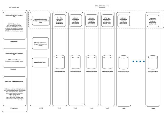
Figure 1 Reference Architecture of SAS VA/VS Distributed Design
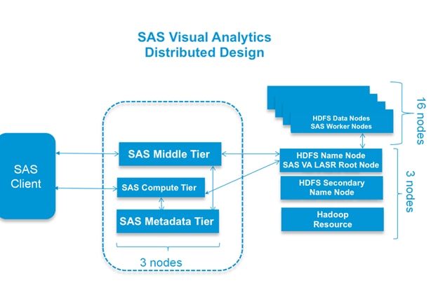
The base configuration of 19 Hadoop nodes with 16 data and 3 management servers plus 3 SAS VA servers are as follows:
· Three Cisco UCS C240 M4 Rack Servers (1 SAS Metadata, 1 SAS Middle Tier, 1 SAS VA compute)
· Nineteen Cisco UCS C240 M4 Rack Servers,
· Three Hadoop Management Nodes (1 x Name Node, 1 x Secondary Name Node and 1 x Resource Manager)
· Sixteen Hadoop Data Nodes
As illustrated in Figure 1, this design helps ensure complete isolation of SAS VA and Hadoop nodes to achieve better availability. At the HDFS level we have HA available at the name node with Primary and Secondary name nodes being configured. LASR Root node co-located with the Name node. In case Primary name node fails, one can simply restart the root node installed on the Secondary Name node and cluster becomes available very quickly. Separation of Web App tier, SAS Meta data server and SAS VA Server provides complete isolation and greater control over the available resources. However, for a typical SAS VA Distributed deployment it is common to deploy all three in a single node.
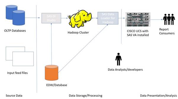
You may have data in various OLTP systems such as Oracle or SAP, EDW, and you may also have an existing Hadoop cluster to store your big data volumes. The aim is to build a new presentation and visual data exploration analysis tool. All the data from these systems can flow into the Cisco UCS Hadoop cluster using various SAS/Access engines. The data flow be set and triggered using SAS Data Loader for Hadoop that will pull the data from various source systems and load it into Hadoop and then they can be loaded into LASR. When the data is in LASR, you can explore the data through creating reports or use SAS Visual Explorer to better understand data.
Figure 2 depicts the hardware configure associated with the reference architecture and placement of the various servers on the physical infrastructure.
Figure 2 Reference Architecture for SAS Visual Analytics
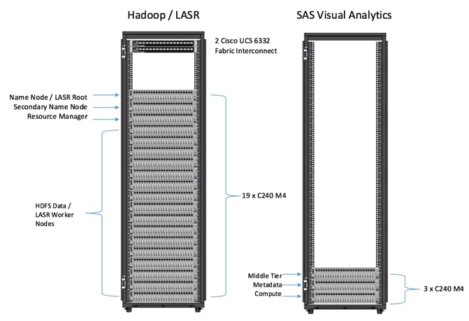
Configuration Details
Table 2 Configuration Details
| Component |
Description |
| Connectivity |
2 Cisco UCS 6332 32-Port Fabric Interconnects |
| Hadoop / LASR Cluster |
19 x Cisco UCS C240 M4 Rack Servers · 3 x Hadoop Name Node/Secondary Name Node and Resource Manager · 16 x Data Nodes. SAS LASR services are collocated on the Data Nodes. *Please refer to Service Assignment section for specific service assignment and configuration details. |
| Visual Analytics Server |
3 x Cisco UCS C240 M4 Rack Servers 1 x SAS VA App Server, 1 x SAS VA Metadata, 1 x SAS VA Compute |
Cisco UCS Integrated Infrastructure for Big Data and Analytics for SAS Visual Analytics
The Cisco UCS Integrated Infrastructure for Big Data and Analytics for SAS Visual Analytics is based on Cisco UCS Integrated Infrastructure for Big Data and Analytics, a highly scalable architecture designed to meet a variety of scale-out application demands with seamless data integration and management integration capabilities built using the following components:
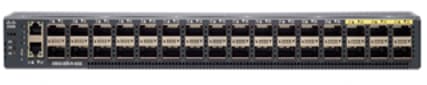
Cisco UCS 6300 Series Fabric Interconnect
The Cisco UCS 6300 Series Fabric Interconnect, as shown in Figure 3, is a core part of Cisco UCS, providing low-latency, lossless 10 and 40 Gigabit Ethernet, Fiber Channel over Ethernet (FCoE), and Fiber Channel functions with management capabilities for the system. All servers attached to the Fabric Interconnects become part of a single, highly available management domain.
Figure 3 Cisco UCS 6332 32 -Port Fabric Interconnect
Cisco UCS C-Series Rack Mount Servers
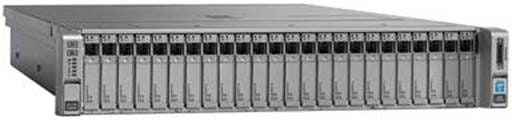
Cisco UCS C240 M4 High-Density Rack Servers (Small Form Factor Disk Drive Model), are enterprise-class systems that support a wide range of computing, I/O and storage-capacity demands in compact designs, as shown in Figure 4. Cisco UCS C-Series Rack-Mount Servers are based on the Intel Xeon E5-2600 v4 series processor family that delivers the best combination of performance, flexibility and efficiency using Cisco 12 Gbps Modular (non-RAID) SAS HBA Controller.
Cisco UCS C240 M4 servers provide 24 DIMMs supporting up to 1.5 TB of main memory. It can support a range of disk drive and SSD options. Specifically, Cisco UCS C240 M4 supports twenty-four Small Form Factor (SFF) disk drives plus two internal SATA boot drives for a total of 26 internal drives. Cisco UCS Virtual Interface cards 1387 (VICs) are designed for the M4 generation of Cisco UCS C-Series Rack Servers and are optimized for high-bandwidth and low-latency cluster connectivity, with support for up to 256 virtual devices that are configured on demand through Cisco UCS Manager.
Figure 4 Cisco UCS C240 M4 Rack Server
Cisco UCS Virtual Interface Cards (VICs)
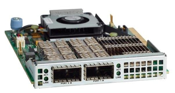
The Cisco UCS Virtual Interface Card 1387 offers dual-port Enhanced Quad Small Form-Factor Pluggable (QSFP) 40 Gigabit Ethernet and Fiber Channel over Ethernet (FCoE) in a modular-LAN-on-motherboard (mLOM) form factor. The mLOM slot can be used to install a Cisco VIC without consuming a PCIe slot providing greater I/O expandability. See Figure 5.
Cisco UCS Manager
Cisco UCS Manager resides within the Cisco UCS 6300 Series Fabric Interconnect (Figure 6). It makes the system self-aware and self-integrating, managing all of the system components as a single logical entity. Cisco UCS Manager can be accessed through an intuitive graphical user interface (GUI), a command-line interface (CLI) or an XML application-programming interface (API). Cisco UCS Manager uses service profiles to define the personality, configuration, and connectivity of all resources within Cisco UCS, radically simplifying provisioning of resources so that the process takes minutes instead of days. This simplification allows IT departments to shift their focus from constant maintenance to strategic business initiatives.
SAS Advanced Analytics
SAS is the market leader in advanced analytics with decades of experience and a broad portfolio of innovative products that help businesses turn data into actionable insight. This design uses advanced tools from SAS for historical and real-time analysis in the data center, including: SAS Visual Analytics (VA) and LASR Analytics Server.
SAS Visual Analytics
SAS Visual Analytics enables organizations to gain insight from all of their data, no matter the size of the data, with no need to subset or sample the data. It is implemented as an integrated suite of web applications that offer intuitive, drag-and-drop interactions, rapid, highly visual responses, and role-based access to functionality.
Users of all skill levels can visually explore data on their own while tapping into powerful in-memory technologies for faster analytic computations and discoveries. It’s an easy-to-use, self-service environment that can scale on an enterprise-wide level. SAS® Visual Analytics is a product to easily allow the interactive analysis of data. The product offers capabilities to analyze data with a visual approach.
SAS LASR Analytics Server
The SAS® LASR™ Analytic Server acts as a back-end, in-memory analytics engine for solutions such as SAS®Visual Analytics and SAS® Visual Statistics. It is designed to exist in a massively scalable, distributed environment, often alongside Hadoop.
SAS Visual Statistics
SAS Visual Statistics is for creating and comparing statistical models in a web-based interface. This will use the capabilities of LASR Analytics server which is the underlying mechanism for Visual Analytics. SAS Visual Statistics is visually and functionally integrated with SAS Visual Analytics web tool named as Visual Analytics Explorer. However, SAS Visual Statistics remains a separately licensed product.
Cloudera (CDH 5.7)
Built on the transformative Apache Hadoop open source software project, Cloudera Enterprise is a hardened distribution of Apache Hadoop and related projects designed for the demanding requirements of enterprise customers. Cloudera is the leading contributor to the Hadoop ecosystem, and has created a rich suite of complementary open source projects that are included in Cloudera Enterprise.
All the integration and the entire solution is thoroughly tested and fully documented. By taking the guesswork out of building out a Hadoop deployment, CDH gives a streamlined path to success in solving real business problems.
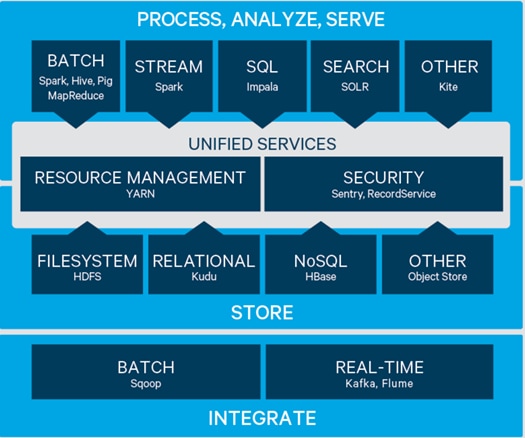
Cloudera Enterprise (Figure 7), with Apache Hadoop is, at its core:
· Unified – one integrated system, bringing diverse users and application workloads to one pool of data on a common infrastructure; no data movement required.
· Secure – perimeter security, authentication, granular authorization, and data protection.
· Governed – enterprise-grade data auditing, data lineage, and data discovery.
· Managed – native high-availability, fault-tolerance and self-healing storage, automated backup and disaster recovery, and advanced system and data management.
· Open – Apache-licensed open source, to ensure both data and applications remain copy righted, and an open platform to connect with all of the existing investments in technology and skills.
Cloudera provides a scalable, flexible, integrated platform that makes it easy to manage rapidly increasing volumes and varieties of data in any enterprise. Industry-leading Cloudera products and solutions enable enterprises to deploy and manage Apache Hadoop and related projects, manipulate and analyze data, and keep that data secure and protected.
Cloudera provides the following products and tools:
· CDH—The Cloudera distribution of Apache Hadoop and other related open-source projects, including Spark. CDH also provides security and integration with numerous hardware and software solutions.
· Cloudera Manager—A sophisticated application used to deploy, manage, monitor, and diagnose issues with CDH deployments. Cloudera Manager provides the Admin Console, a web-based user interface that makes administration of any enterprise data simple and straightforward. It also includes the Cloudera Manager API, which can be used to obtain cluster health information and metrics, as well as configure Cloudera Manager.
· Cloudera Navigator—An end-to-end data management tool for the CDH platform. Cloudera Navigator enables administrators, data managers, and analysts to explore the large amounts of data in Hadoop. The robust auditing, data management, lineage management, and life cycle management in Cloudera Navigator allow enterprises to adhere to stringent compliance and regulatory requirements.
Requirements
This CVD describes architecture and deployment procedures for Cloudera (CDH 5.7) on a Cisco UCS C240 M4 node cluster based on Cisco UCS Integrated Infrastructure for Big Data and Analytics using the Extreme Performance configuration. The solution goes into detail configuring SAS Visual Analytics with LASR and CDH 5.7 on the infrastructure.
The Extreme Performance cluster configuration consists of the following:
· 2 Cisco UCS 6332 Fabric Interconnects
· 22 Cisco UCS C240 M4 Rack-Mount servers
· 2 Cisco R42610 standard racks
· 4 Vertical Power distribution units (PDUs) (Country Specific)
Figure 8 depicts the deployment of various SAS server tiers and their components on the physical infrastructure. In the above design SAS LASR Analytics server co-locates with Hadoop Data nodes. For better isolation SAS Metadata, SAS Web-App Serer and SAS VA Compute server are deployed in 3 individual servers.
Figure 8 Component Level deployment of SAS Visual Analytics 7.3
SAS VA Server Tier Storage Requirement
Table 3 Storage Placement and Requirement
| Environment |
Hostname |
Filesystem |
Directory |
Description |
Size |
| Production |
Metadata |
/data/disk1 |
/data/disk1/sas/sashome |
SAS Metadata Installation |
300 GB |
|
/data/disk1/sas/sasconf |
SAS Metadata Configuration |
||||
| Production |
VA-Compute |
/data/disk1 |
/data/disk1/sas/sashome |
SAS Compute Installation |
400 GB |
| /data/disk1/sas/sasconf |
SAS Compute Configuration |
||||
|
/data/disk1/sas/saswork |
SAS Work Location |
||||
| Production |
VA-App-Server |
/data/disk1 |
/data/disk1/sas/sashome |
SAS Middle Tier Installation |
450 GB |
| /data/disk1/sas/sasconf |
SAS Middle Tier Configuration |
Rack and PDU Configuration
Two racks will be used with two vertical PDUs each. One rack will have two Cisco UCS 6332 Fabric Interconnects, nineteen Cisco UCS C240 M4 Servers connected to each of the vertical PDUs for redundancy; thereby, ensuring availability during power source failure. The second rack will have three Cisco UCS C240 M4 Servers connected to each of the vertical PDUs for redundancy, ensuring availability during power source failure.
![]() Note: Please contact your Cisco representative for country specific information.
Note: Please contact your Cisco representative for country specific information.
Table 4 describes the rack configurations for both racks.
| Cisco |
Rack 1 (Master) |
Cisco |
Rack 2 (Expansion) |
| 42URack |
|
42URack |
|
| 42 |
Cisco UCS FI 6332 |
42 |
Unused |
| 41 |
Cisco UCS FI 6332 |
41 |
Unused |
| 40 |
Unused
|
40 |
Unused
|
| 39 |
39 |
||
| 38 |
Cisco UCS C240 M4 |
38 |
Unused
|
| 37 |
37 |
||
| 36 |
Cisco UCS C240 M4 |
36 |
Unused
|
| 35 |
35 |
||
| 34 |
Cisco UCS C240 M4 |
34 |
Unused |
| 33 |
33 |
||
| 32 |
Cisco UCS C240 M4 |
32 |
Unused |
| 31 |
31 |
||
| 30 |
Cisco UCS C240 M4 |
30 |
Unused |
| 29 |
29 |
||
| 8 |
Cisco UCS C240 M4 |
28 |
Unused |
| 27 |
27 |
||
| 26 |
Cisco UCS C240 M4 |
26 |
Unused |
| 25 |
25 |
||
| 24 |
Cisco UCS C240 M4 |
24 |
Unused |
| 23 |
23 |
||
| 22 |
Cisco UCS C240 M4 |
22 |
Unused |
| 21 |
21 |
||
| 20 |
Cisco UCS C240 M4 |
20 |
Unused |
| 19 |
19 |
||
| 18 |
Cisco UCS C240 M4 |
18 |
Unused |
| 17 |
17 |
||
| 16 |
Cisco UCS C240 M4 |
16 |
Unused |
| 15 |
15 |
||
| 14 |
Cisco UCS C240 M4 |
14 |
Unused |
| 13 |
13 |
||
| 12 |
Cisco UCS C240 M4 |
12 |
Unused |
| 11 |
11 |
||
| 10 |
Cisco UCS C240 M4 |
10 |
Unused |
| 9 |
9 |
||
| 8 |
Cisco UCS C240 M4 |
8 |
Unused |
| 7 |
7 |
||
| 6 |
Cisco UCS C240 M4 |
6 |
Cisco UCS C240 M4 |
| 5 |
5 |
||
| 4 |
Cisco UCS C240 M4 |
4 |
Cisco UCS C240 M4 |
| 3 |
3 |
||
| 2 |
Cisco UCS C240 M4 |
2 |
Cisco UCS C240 M4 |
| 1 |
1 |
Table 5 Port Configuration on Cisco UCS Fabric Interconnects
| Port Type |
Port Number |
| Network |
1-2 |
| Server |
3 to 24 |
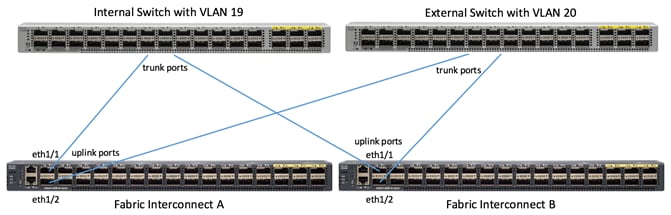
Uplink Connectivity and Configuration
Figure 9 shows the connectivity from the fabric interconnect to the uplink switches. There are two separate switches, one internal, the other external. In this configuration the internal switch includes vlan19, and the external switch includes vlan20.
Server Configuration and Cabling for Cisco UCS C240 M4
The Cisco UCS C240 M4 Rack Server is equipped with Intel Xeon E5-2690 v4 processors, 512 GB of memory, Cisco UCS Virtual Interface Card 1387, Cisco 12Gbps Modular (non-RAID) SAS HBA Controller, 8 Intel S3510 1.6 TB SSD, 2 240-GB SATA SSD for Boot.
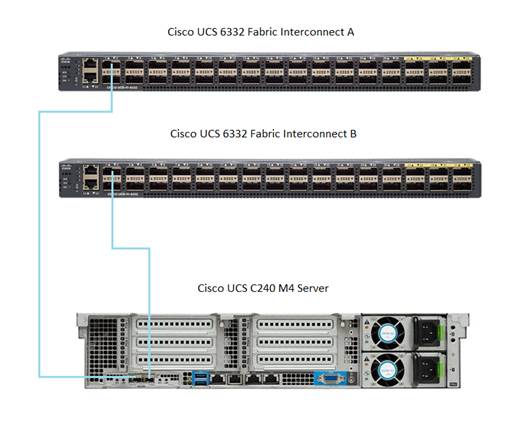
Figure 10 illustrates the port connectivity between the Fabric Interconnect, and Cisco UCS C240 M4 server. Twenty-two Cisco UCS C240 M4 servers are used in two racks.
Figure 10 Fabric Topology for Cisco UCS C240 M4
For more information about physical connectivity and single-wire management see:
For more information about physical connectivity illustrations and cluster setup, see:
Software Distributions and Versions
The required software distribution versions are listed in the following sections.
Cloudera (CDH 5.7)
The Cloudera Distribution for Apache Hadoop version used is 5.7. For more information visit www.cloudera.com.
Red Hat Enterprise Linux (RHEL)
The operating system supported is Red Hat Enterprise Linux 7.2. For more information visit http://www.redhat.com.
SAS Visual Analytics (7.3)
The SAS Visual Analytics distributed environment (MPP) version used is 7.3 . For more information visit https://www.sas.com.
Software Versions
The software versions tested and validated in this document are shown in Table 6.
| Layer |
Component |
Version or Release |
| Compute |
Cisco UCS C240-M4 |
C240M4.2.0.13g |
| Network |
Cisco UCS 6332 |
UCS 3.1(2e) A |
| Cisco UCS VIC1387 Firmware |
4.1.2(d) |
|
| Cisco UCS VIC1387 Driver |
2.3.0.20 |
|
| Storage |
SAS HBA Driver |
mpt3sas-12.00.00.00-3 |
|
|
Red Hat Enterprise Linux Server |
7.2 (x86_64) |
| Software |
Cisco UCS Manager |
3.1(2e) |
| CDH |
5.7.0 |
|
| SAS Visual Analytics |
7.3 |
![]() The latest drivers can be downloaded from the link below:
The latest drivers can be downloaded from the link below:
https://software.cisco.com/download/release.html?mdfid=283862063&flowid=25886&softwareid=283853158&release=1.5.7d&relind=AVAILABLE&rellifecycle=&reltype=latest
![]() The latest supported SAS HBA controller driver is already included with the RHEL 7.2 operating system.
The latest supported SAS HBA controller driver is already included with the RHEL 7.2 operating system.
![]() Cisco UCS C240 M4 Rack Servers with Broadwell (E5 -2600 v4) CPUs are supported by Cisco UCS firmware 3.1(1g) and newer.
Cisco UCS C240 M4 Rack Servers with Broadwell (E5 -2600 v4) CPUs are supported by Cisco UCS firmware 3.1(1g) and newer.
End-to-End Installation Flow Chart
Figure 11 Flow Chart for Cisco UCS and Hadoop Installation Process

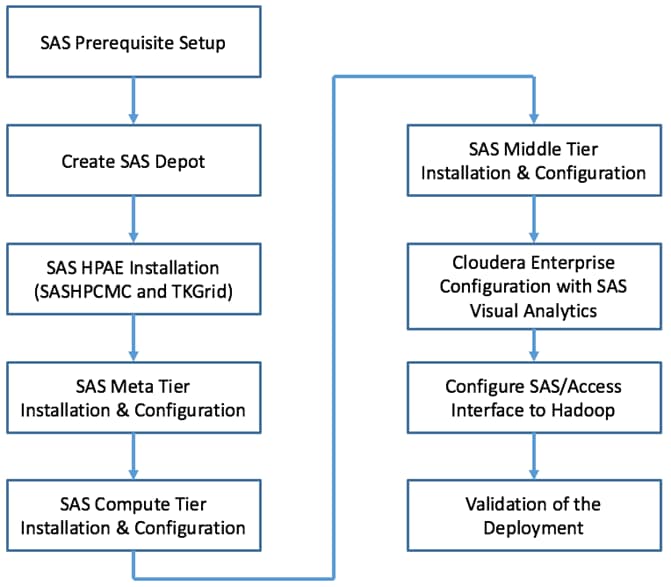
Figure 12 Flow Chart for SAS Visual Analytics Installation Process
Fabric Configuration
This section provides the details to configure a pair of fully redundant, highly available Cisco UCS 6332 Fabric Interconnects:
· Initial setup of the Fabric Interconnect A and B
· Open Cisco UCS Manager’s web interface using the cluster IP address
· Launch Cisco UCS Manager
· Enable server and uplink ports
· Start discovery process
· Create pools and polices for service profile template
· Create Service Profile template for Hadoop and another template for VA / VS
· Create Service profiles based on those templates
Performing Initial Setup of Cisco UCS 6332 Fabric Interconnects
This section describes the initial setup of the Cisco UCS 6332 Fabric Interconnects A and B.
Configure Fabric Interconnect A
To configure Fabric Interconnect A, complete the following steps:
1. Connect to the console port on the first Cisco UCS 6332 Fabric Interconnect.
2. At the prompt to enter the configuration method, enter console to continue.
3. If asked to either perform a new setup or restore from backup, enter setup to continue.
4. Enter y to continue to set up a new Fabric Interconnect.
5. Enter y to enforce strong passwords.
6. Enter the password for the admin user.
7. Enter the same password again to confirm the password for the admin user.
8. When asked if this fabric interconnect is part of a cluster, answer y to continue.
9. Enter A for the switch fabric.
10. Enter the cluster name for the system name.
11. Enter the Mgmt0 IPv4 address.
12. Enter the Mgmt0 IPv4 netmask.
13. Enter the IPv4 address of the default gateway.
14. Enter the cluster IPv4 address.
15. To configure DNS, answer y.
16. Enter the DNS IPv4 address.
17. Answer y to set up the default domain name.
18. Enter the default domain name.
19. Review the settings that were printed to the console, and if they are correct, answer yes to save the configuration.
20. Wait for the login prompt to make sure the configuration has been saved.
Configure Fabric Interconnect B
To configure Fabric Interconnect B, complete the following steps:
1. Connect to the console port on the second Cisco UCS 6332 Fabric Interconnect.
2. When prompted to enter the configuration method, enter console to continue.
3. The installer detects the presence of the partner Fabric Interconnect and adds this fabric interconnect to the cluster. Enter y to continue the installation.
4. Enter the admin password that was configured for the first Fabric Interconnect.
5. Enter the Mgmt0 IPv4 address.
6. Answer yes to save the configuration.
7. Wait for the login prompt to confirm that the configuration has been saved.
For more information on configuring Cisco UCS 6300 Series Fabric Interconnect, see: http://www.cisco.com/c/en/us/support/servers-unified-computing/ucs-manager/products-installation-and-configuration-guides-list.html
Logging Into Cisco UCS Manager
To login to Cisco UCS Manager, complete the following steps:
1. Open a Web browser and navigate to the Cisco UCS 6332 Fabric Interconnect cluster address.
2. Click the Launch link to download the Cisco UCS Manager software.
3. If prompted to accept security certificates, accept as necessary.
4. When prompted, enter admin for the username and enter the admin password.
5. Click Login to log into the Cisco UCS Manager.
Upgrading Cisco UCS Manager Software to Version 3.1(2e)
This document assumes the use of Cisco UCS 3.1(2e) Refer to Cisco UCS 3.1 Release (upgrade the Cisco UCS Manager software and Cisco UCS 6332 Fabric Interconnect software to version 3.1(2e). Also, make sure the Cisco UCS C-Series version 3.1(2e) software bundles is installed on the Fabric Interconnects.
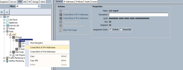
Adding a Block of IP Addresses for KVM Access
To create a block of KVM IP addresses for server access in the Cisco UCS environment, complete the following steps:
1. Select the LAN tab at the top of the left window.
2. Select Pools > IpPools > Ip Pool ext-mgmt.
3. Right-click IP Pool ext-mgmt.
4. Select Create Block of IPv4 Addresses.
Figure 13 Adding a Block of IPv4 Addresses for KVM Access Part 1
5. Enter the starting IP address of the block and number of IPs needed, as well as the subnet and gateway information. Set the size to 22.
Figure 14 Adding Block of IPv4 Addresses for KVM Access Part 2
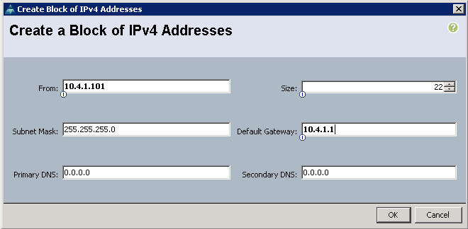
6. Click OK to create the IP block.
7. Click OK in the message box.
Configuring VLANs
VLANs are configured as in shown in Table 7.
| VLAN 19 |
Internal network for Hadoop |
| VLAN 20 |
External network for SAS VA App Server |
To configure VLANs in the Cisco UCS Manager GUI, complete the following steps:
1. Select the LAN tab in the left pane in the Cisco UCS Manager GUI.
2. Select LAN > LAN Cloud > VLANs.
3. Right-click the VLANs under the root organization.
4. Select Create VLANs to create the VLAN.
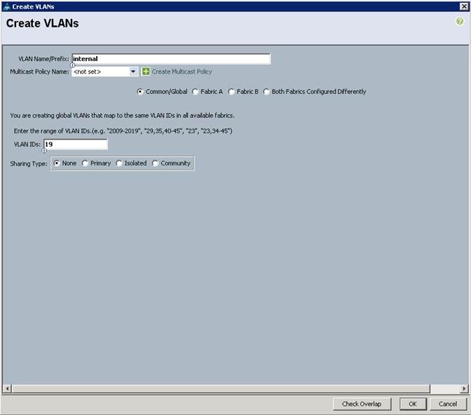
Figure 15 Creating a VLAN

5. Enter internal for the VLAN Name.
6. Keep multicast policy as <not set>.
7. Select Common/Global
8. Enter 19 in the VLAN IDs field.
9. Click OK and then, click Finish.
10. Click OK in the success message box.
Figure 16 Creating VLAN for Data
8. Click OK and then, click Finish.
Repeat above steps to create another VLAN using external for VLAN Name and 20 for VLAN ID.
Enabling Uplink Ports
To enable uplinks ports, complete the following steps:
1. Select the Equipment tab on the top left of the window.
2. Select Equipment > Fabric Interconnects > Fabric Interconnect A > Fixed Module > Ethernet Ports.
3. Select port 1 and 2 that is connected to the uplink switch, right-click, and then select Configure as Uplink Port.
4. A pop-up window appears to confirm your selection. Click yes then OK to continue.
5. Select Show Interface and select 40GB for the admin speed.
6. Select Equipment > Fabric Interconnects > Fabric Interconnect B > Fixed Module > Ethernet Ports.
7. Select port 1 and 2 that is connected to the uplink switch, right-click, and then select Configure as Uplink Port.
8. A pop-up window appears to confirm your selection. Click yes then OK to continue.
9. Select Show Interface and select 40GB for the admin speed.
Figure 17 Enabling Uplink Ports

Create LAN Pin Group
LAN Pin Groups are needed to assign one uplink port to the internal switch and one uplink port to the external switch. See Figure 9 and Figure 10. To create a LAN Pin Group, complete the following steps:
1. Select the LAN tab on the top left of the window.
2. Expand LAN Cloud.
3. Right-click LAN Pin Groups and select Create LAN Pin Group.
4. Enter internal for Name, check Fabric A and Fabric B and select uplink ports eth interface 1/1 for both. This should be going to the internal switch.
5. Click OK.
6. Repeat the above steps to create another LAN Pin Group named external, then select the uplink ports eth interface 1/2 for both Fabric A and Fabric B. These should be pointed to the external switch.

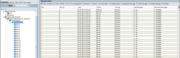
Enabling Server Ports
To enable server ports, complete the following steps:
1. Select the Equipment tab on the top left of the window.
2. Select Equipment > Fabric Interconnects > Fabric Interconnect A > Fixed Module > Ethernet Ports.
3. Select all the ports that are connected to the servers (3 to 24), right-click them, and select Configure as a Server Port.
4. A pop-up window appears to confirm your selection. Click yes then OK to continue.
5. Select Equipment > Fabric Interconnects > Fabric Interconnect B > Fixed Module > Ethernet Ports.
6. Select all the ports that are connected to the servers (3 to 24), right-click them, and select Configure as a Server Port.
7. A pop-up window appears to confirm your selection. Click yes, then OK to continue.
Figure 18 Enabling Server Ports
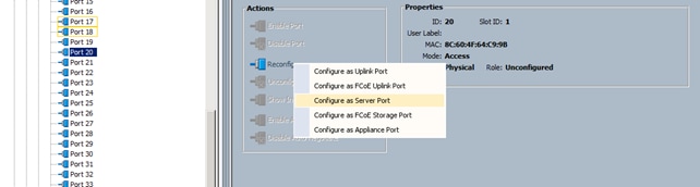
After the Server Discovery, Port 1-2 will be network ports and 3-24 will be server ports.
Creating Pools for Service Profile Templates
Creating an Organization
Organizations are used as a means to arrange and restrict access to various groups within the IT organization, thereby enabling multi-tenancy of the compute resources. This document does not assume the use of Organizations; however the necessary steps are provided for future reference.
To configure an organization within the Cisco UCS Manager GUI, complete the following steps:
1. Click New on the top left corner in the right pane in the Cisco UCS Manager GUI.
2. Select Create Organization from the options.
3. Enter a name for the organization.
4. (Optional) Enter a description for the organization.
5. Click OK.
6. Click OK in the success message box.
Creating MAC Address Pools
To create MAC address pools, complete the following steps:
1. Select the LAN tab on the left of the window.
2. Select Pools > root.
3. Right-click MAC Pools under the root organization.
4. Select Create MAC Pool to create the MAC address pool. Enter ucs for the name of the MAC pool.
5. (Optional) Enter a description of the MAC pool.
6. Select Assignment Order Sequential.
7. Click Next.
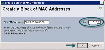
8. Click Add.
9. Specify a starting MAC address.
10. Specify a size of the MAC address pool, which is sufficient to support the available server resources.
11. Click OK.
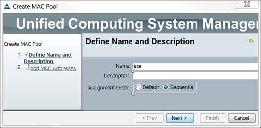
Figure 19 Specifying first MAC Address and Size
12. Click Finish.
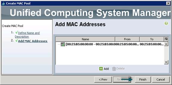
13. When the message box displays, click OK.
Creating a Server Pool “ucs”
A server pool contains a set of servers. These servers typically share the same characteristics. Those characteristics can be their location in the chassis, or an attribute such as server type, amount of memory, local storage, type of CPU, or local drive configuration. You can manually assign a server to a server pool, or use server pool policies and server pool policy qualifications to automate the assignment
To configure the server pool within the Cisco UCS Manager GUI, complete the following steps:
1. Select the Servers tab in the left pane in the Cisco UCS Manager GUI.
2. Select Pools > root.
3. Right-click the Server Pools.
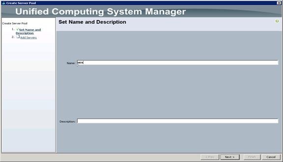
4. Select Create Server Pool.
5. Enter your required name (ucs) for the Server Pool in the name text box.
6. (Optional) enter a description for the organization.
7. Click Next > to add the servers.
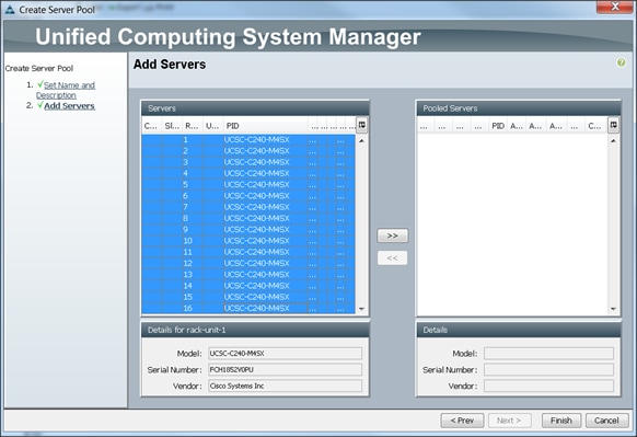
8. Select 1-19 Cisco UCS C240M4 servers to be added to the server pool that was previously created (ucs), then Click >> to add them to the pool.
9. Click Finish.
10. Click OK and then click Finish.
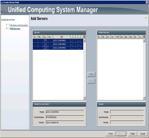
Creating a Server Pool “ucs-va-app”
To create a server "ucs-va-app", complete the following steps:
1. Select the Servers tab in the left pane in the Cisco UCS Manager GUI.
2. Select Pools > root.
3. Right-click the Server Pools.
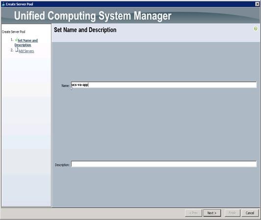
4. Select Create Server Pool.
5. Enter your required name (ucs-va-app) for the Server Pool in the name text box.
6. (Optional) enter a description for the organization.
7. Click Next > to add the servers.
8. Select 20, 21, 22 Cisco UCS C240M4 servers to be added to the server pool that was previously created (ucs-va-app), then Click >> to add them to the pool.
9. Click Finish.
10. Click OK and then click Finish.
Creating Policies for Service Profile Templates
Creating Host Firmware Package Policy
Firmware management policies allow the administrator to select the corresponding packages for a given server configuration. These include adapters, BIOS, board controllers, FC adapters, HBA options, and storage controller properties as applicable.
To create a firmware management policy for a given server configuration using the Cisco UCS Manager GUI, complete the following steps:
1. Select the Servers tab in the left pane in the UCS Manager GUI.
2. Select Policies > root.
3. Right-click Host Firmware Packages.
4. Select Create Host Firmware Package.
5. Enter the required Host Firmware package name (ucs).
6. Select Simple radio button to configure the Host Firmware package.
7. Select the appropriate Rack package that has been installed.
8. Click OK to complete creating the management firmware package
9. Click OK.

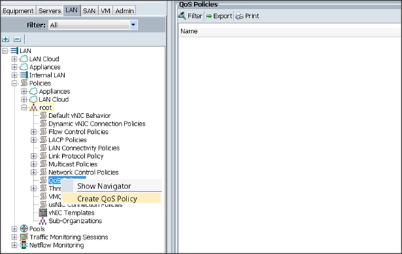
Creating QoS Policies
To create the QoS policy for a given server configuration using the Cisco UCS Manager GUI, complete the following steps:
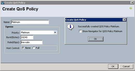
Platinum Policy
1. Select the LAN tab in the left pane in the Cisco UCS Manager GUI.
2. Select Policies > root.
3. Right-click QoS Policies.
4. Select Create QoS Policy.
5. Enter Platinum as the name of the policy.
6. Select Platinum from the drop down menu.
7. Keep the Burst(Bytes) field set to default (10240).
8. Keep the Rate(Kbps) field set to default (line-rate).
9. Keep Host Control radio button set to default (none).
10. When the pop-up window appears, click OK to complete the creation of the Policy.
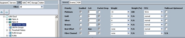
Setting Jumbo Frames
To set Jumbo frames and enable QoS, complete the following steps:
1. Select the LAN tab in the left pane in the UCSM GUI.
2. Select LAN Cloud > QoS System Class.
3. In the right pane, select the General tab
4. In the Platinum row, enter 9216 for MTU.
5. Check the Enabled check box next to Platinum.
6. In the Best Effort row, select none for weight.
7. In the Fiber Channel row, select none for weight.
8. Click Save Changes.
9. Click OK.
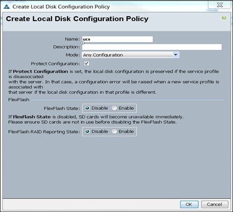
Creating the Local Disk Configuration Policy
To create local disk configuration in the Cisco UCS Manager GUI, complete the following steps:
1. Select the Servers tab on the left pane in the Cisco UCS Manager GUI.
2. Go to Policies > root.
3. Right-click Local Disk Config Policies.
4. Select Create Local Disk Configuration Policy.
5. Enter ucs as the local disk configuration policy name.
6. Change the Mode to Any Configuration. Check the Protect Configuration box.
7. Keep the FlexFlash State field as default (Disable).
8. Keep the FlexFlash RAID Reporting State field as default (Disable).
9. Click OK to complete the creation of the Local Disk Configuration Policy.
10. Click OK.
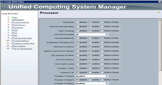
Creating Server BIOS Policy
The BIOS policy feature in Cisco UCS automates the BIOS configuration process. The traditional method of setting the BIOS is manually, and is often error-prone. By creating a BIOS policy and assigning the policy to a server or group of servers, can enable transparency within the BIOS settings configuration.
![]() Note: BIOS settings can have a significant performance impact, depending on the workload and the applications. The BIOS settings listed in this section is for configurations optimized for best performance which can be adjusted based on the application, performance, and energy efficiency requirements.
Note: BIOS settings can have a significant performance impact, depending on the workload and the applications. The BIOS settings listed in this section is for configurations optimized for best performance which can be adjusted based on the application, performance, and energy efficiency requirements.
To create a server BIOS policy using the Cisco UCS Manager GUI, complete the following steps:
1. Select the Servers tab in the left pane in the Cisco UCS Manager GUI.
2. Select Policies > root.
3. Right-click BIOS Policies.
4. Select Create BIOS Policy.
5. Enter your preferred BIOS policy name (ucs).
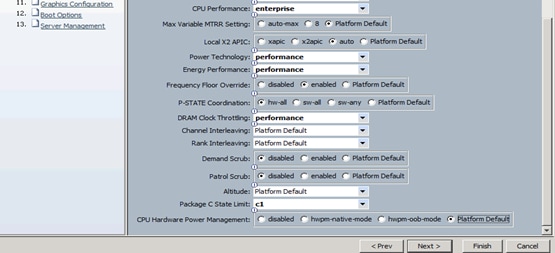
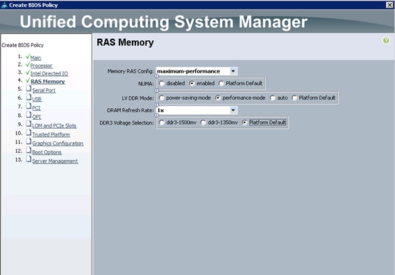
6. Change the BIOS settings as shown in the following figures.
7. Only changes that need to be made are in the Processor and RAS Memory settings.
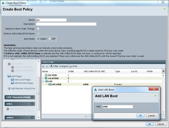
Creating the Boot Policy
To create boot policies within the Cisco UCS Manager GUI, complete the following steps:
1. Select the Servers tab in the left pane in the Cisco UCS Manager GUI.
2. Select Policies > root.
3. Right-click the Boot Policies.
4. Select Create Boot Policy.

5. Enter ucs as the boot policy name.
6. (Optional) enter a description for the boot policy.
7. Keep the Reboot on Boot Order Change check box unchecked.
8. Keep Enforce vNIC/vHBA/iSCSI Name check box checked.
9. Keep Boot Mode Default (Legacy).
10. Expand Local Devices > Add CD/DVD and select Add Local CD/DVD.
11. Expand Local Devices and select Add Local Disk.
12. Expand vNICs and select Add LAN Boot and enter eth0.
13. Click OK to add the Boot Policy.
14. Click OK.
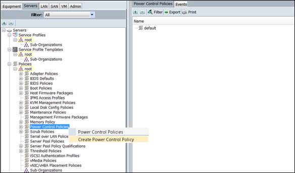
Creating Power Control Policy
To create Power Control policies within the Cisco UCS Manager GUI, complete the following steps:
1. Select the Servers tab in the left pane in the Cisco UCS Manager GUI.
2. Select Policies > root.
3. Right-click the Power Control Policies.
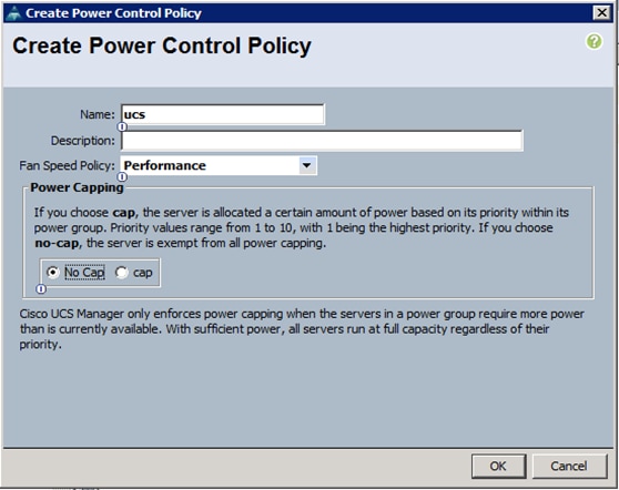
4. Select Create Power Control Policy.
5. Enter ucs as the Power Control policy name.
6. (Optional) enter a description for the boot policy.
7. Select Performance for Fan Speed Policy.
8. Select No cap for Power Capping selection.
9. Click OK to create the Power Control Policy.
10. Click OK.
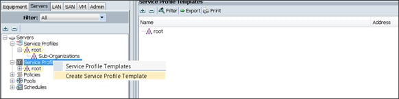
Creating a Service Profile Template for Hadoop
To create a Service Profile Template, complete the following steps:
1. Select the Servers tab in the left pane in the Cisco UCS Manager GUI.
2. Right-click Service Profile Templates.
3. Select Create Service Profile Template.
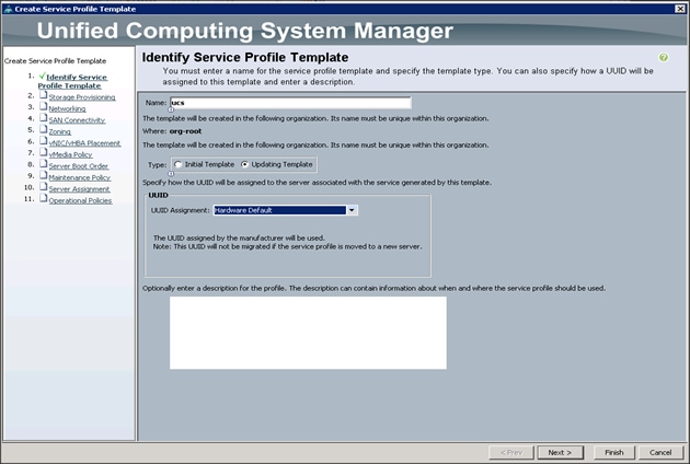
The Create Service Profile Template window appears.
To identify the service profile template, complete the following steps:
1. Name the service profile template as ucs. Select the Updating Template radio button.
2. In the UUID section, select Hardware Default as the UUID pool.
3. Click Next to continue to the next section.
Configuring the Storage Provisioning for the Template
To configure storage policies, complete the following steps:
1. Go to the Local Disk Configuration Policy tab, and select ucs for the Local Storage.
2. Click Next.
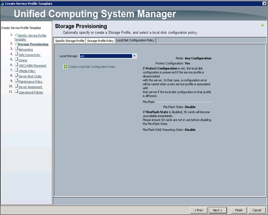
3. Click Next when the Networking window appears to go to the next section.
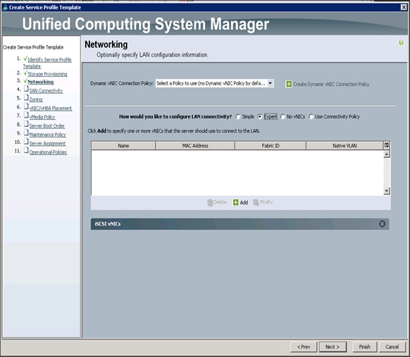
Configuring Network Settings for the Template
To configure the network settings for the template, complete the following steps:
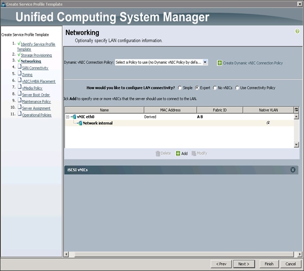
1. Keep the Dynamic vNIC Connection Policy field at the default.
2. Select Expert radio button for the option how would you like to configure LAN connectivity?
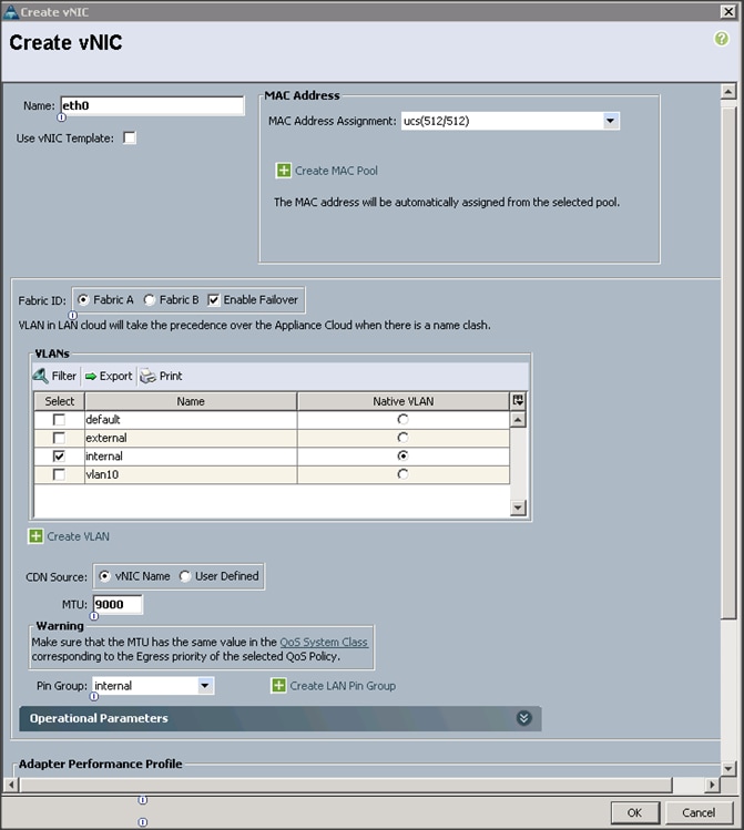
3. Click Add to add a vNIC to the template.
4. The Create vNIC window displays. Name the vNIC as eth0.
5. Select ucs in the Mac Address Assignment pool.
6. Select the Fabric A radio button and check the Enable failover check box for the Fabric ID.
7. Check the internal check box for VLANs and select the Native VLAN radio button.
8. Select MTU size as 9000.
9. Select Pin Group as internal.
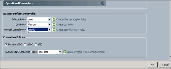
10. Select adapter policy as Linux.
11. Select QoS Policy as Platinum.
12. Keep the Network Control Policy as Default.
13. Click OK.
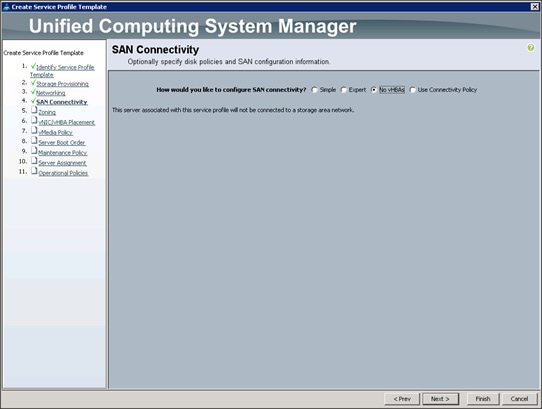
14. Click Next to continue with SAN Connectivity.
15. Select no vHBAs for How would you like to configure SAN Connectivity?
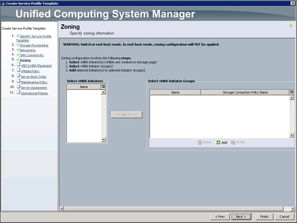
16. Click Next to continue with Zoning.
17. Click Next to continue with vNIC/vHBA placement.
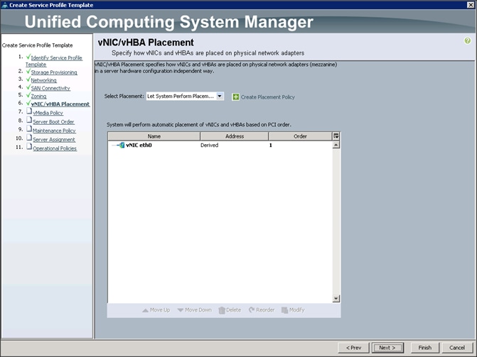
18. Click Next to configure vMedia Policy.
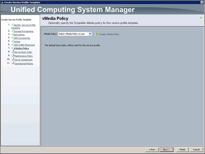
Configuring the vMedia Policy for the Template
To configure the vMedia Policy for the template, complete the following steps:
1. Click Next when the vMedia Policy window appears to go to the next section.
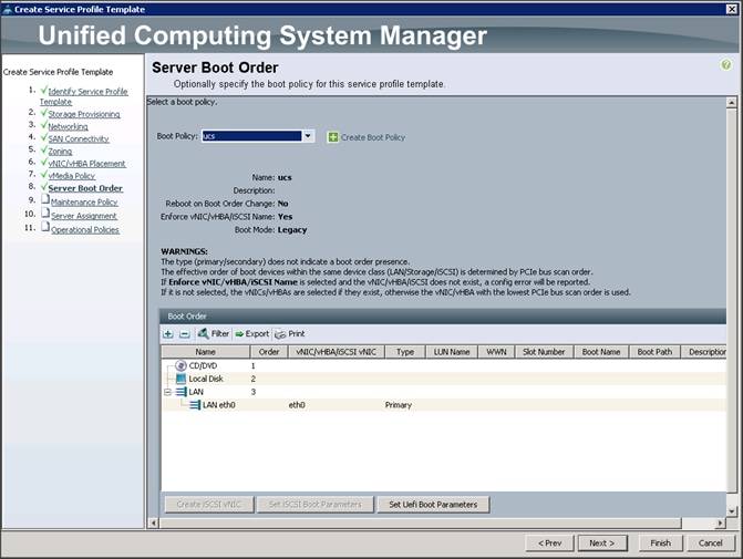
Configuring Server Boot Order for the Template
To set the boot order for the servers, complete the following steps:
1. Select ucs in the Boot Policy name field.
2. Review to make sure that all of the boot devices were created and identified.
3. Verify that the boot devices are in the correct boot sequence.
4. Click OK.
5. Click Next to continue to the next section.
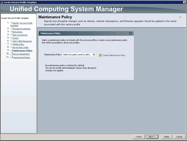
6. In the Maintenance Policy window, apply the maintenance policy.
7. Keep the Maintenance policy at no policy used by default. Click Next to continue to the next section.
Configuring Server Assignment for the Template
In the Server Assignment window, to assign the servers to the pool, complete the following steps:
1. Select ucs for the Pool Assignment field.
2. Select the power state to be Up.
3. Keep the Server Pool Qualification field set to <not set>.
4. Check the Restrict Migration check box.
5. Select ucs in Host Firmware Package.
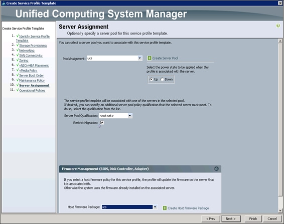
Configuring Operational Policies for the Template
In the Operational Policies Window, complete the following steps:
1. Select ucs in the BIOS Policy field.
2. Select ucs in the Power Control Policy field.

3. Click Finish to create the Service Profile template.
4. Click OK in the pop-up window to proceed.
Create Service Profiles from Service Profile Template Hadoop
To create service profiles, complete the following steps:
1. Select the Servers tab in the left pane of the Cisco UCS Manager GUI.
2. Go to Service Profile Templates > root.
3. Right-click Service Profile Templates ucs.
4. Select Create Service Profiles From Template.
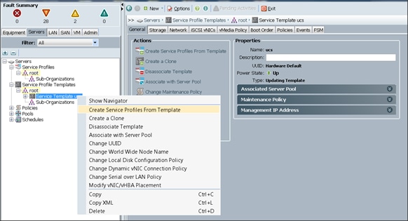
The Create Service Profiles from Template window appears.
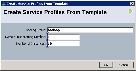
5. Enter Hadoop for Naming Prefix and change Number of Instances to 19.
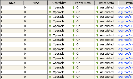
6. Click OK.
7. Association of the Service Profiles will start automatically, taking servers from the server pool created earlier. This process takes 15-20 minutes, after which the Equipment tab will show all the servers as associated.
Creating a Service Profile Template for SAS VA
To create a Service Profile Template for SAS VA, complete the following steps:
1. Click the Servers tab, go to Service Profile Template > root.
2. Right-click the existing template ucs and click Create a Clone.
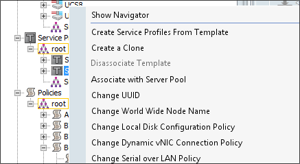
3. In the Clone Name, enter SAS-VA and click OK.
4. Select the new Service Profile Template named SAS-VA and under the General tab click Associate with Server Pool.
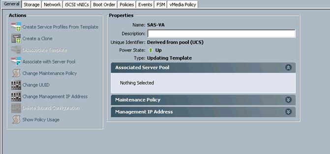
5. For Pool Assignment, select ucs-va-app and click OK.
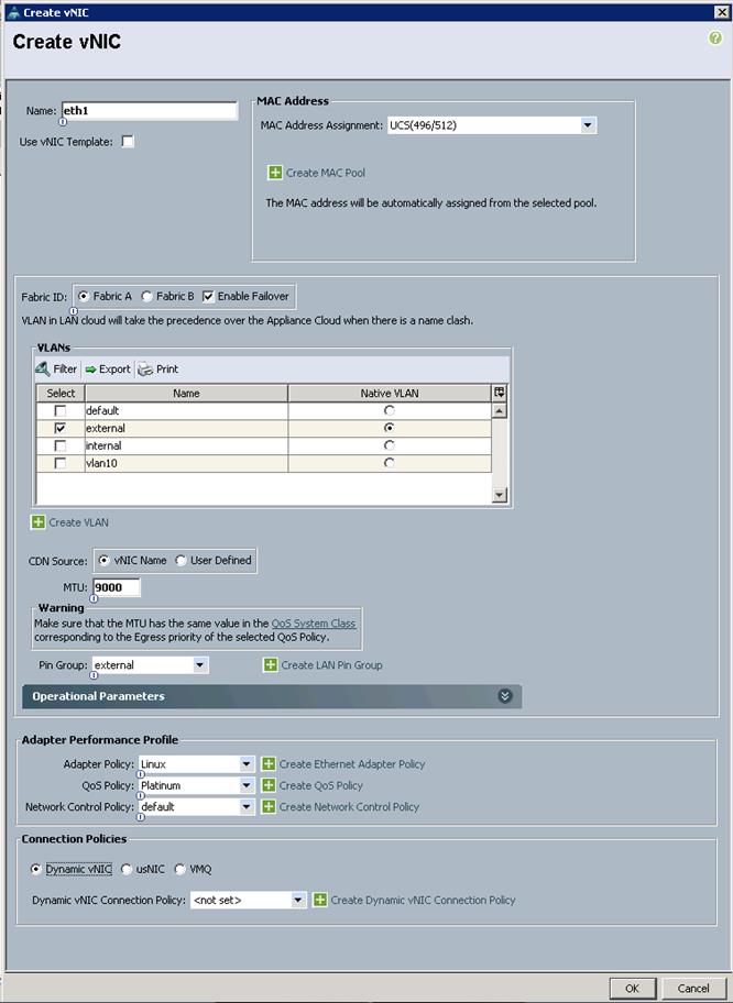
6. Still inside Service Profile Template SAS-VA, select the Network Tab, then under vNICs click add
7. Name the vNIC as eth1.
8. Select ucs in the Mac Address Assignment pool.
9. Select the Fabric A radio button and check the Enable failover check box for the Fabric ID.
10. Check the external check box for VLANs and select the Native VLAN radio button.
11. Select MTU size as 9000.
12. Select Pin Group as external.
13. Select adapter policy as Linux.
14. Select QoS Policy as Platinum.
15. Keep the Network Control Policy as Default.
16. Click OK.
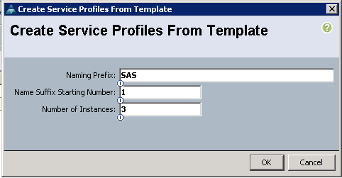
Create Service Profiles from Service Profile Template SAS-VA
To create service profiles, complete the following steps:
1. Right-click the Service Profile Template SAS-VA and select Create Service Profiles from Template.
2. Enter SAS for the Naming Prefix and change number of instances to 3.
3. Click OK.
4. Association of the Service Profiles will start automatically, taking servers from the server pool ucs-va-app. This process takes 15-20 minutes, after which the Equipment tab will show all the servers as associated.
Installing Red Hat Enterprise Linux 7.2
This section provides detailed procedures for installing Red Hat Enterprise Linux 7.2 using Software RAID (OS based Mirroring) on all servers. There are multiple ways to install the Red Hat Linux operating system. The installation procedure described in this deployment guide uses KVM console and virtual media from Cisco UCS Manager.
![]() Note: This requires RHEL 7.2 DVD/ISO for the installation.
Note: This requires RHEL 7.2 DVD/ISO for the installation.
To install the Red Hat Linux 7.2 operating system, complete the following steps:
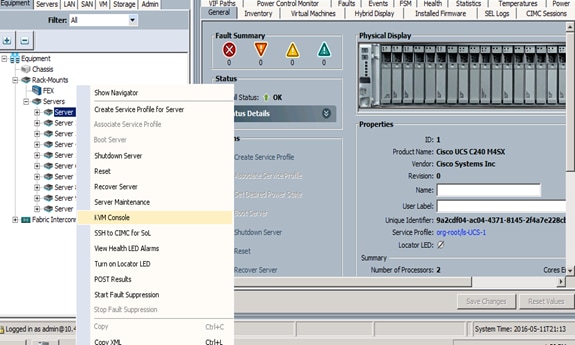
1. Log in to the Cisco UCS Manager.
2. Select the Equipment tab.
3. In the navigation pane expand Rack-Mounts and then Servers.
4. Right click on the server and select KVM Console.
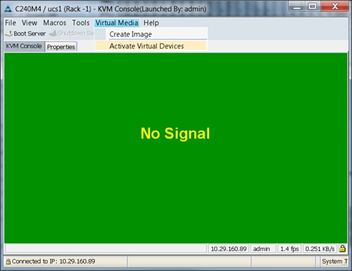
5. In the KVM window, select the Virtual Media tab.
6. Click the Activate Virtual Devices found in Virtual Media tab.
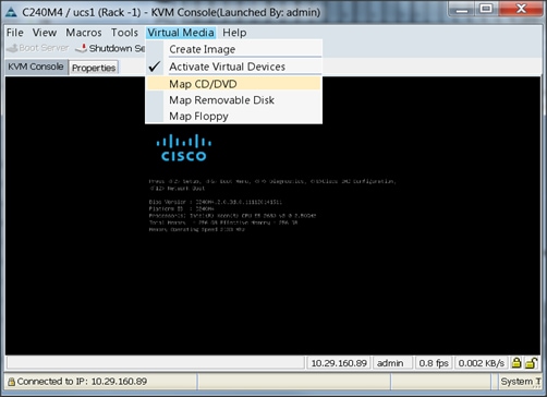
7. In the KVM window, select the Virtual Media tab and click the Map CD/DVD.
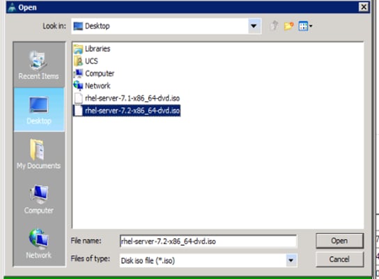
8. Browse to the Red Hat Enterprise Linux Server 7.2 installer ISO image file.
![]() Note: The Red Hat Enterprise Linux 7.2 DVD is assumed to be on the client machine.
Note: The Red Hat Enterprise Linux 7.2 DVD is assumed to be on the client machine.
9. Click Open to add the image to the list of virtual media.
10. In the KVM window, select the KVM tab to monitor during boot.
11. In the KVM window, select the Macros > Static Macros > Ctrl-Alt-Del button in the upper left corner.
12. Click OK.
13. Click OK to reboot the system.
14. On reboot, the machine detects the presence of the Red Hat Enterprise Linux Server 7.2 install media.
15. Select the Install or Upgrade an Existing System.
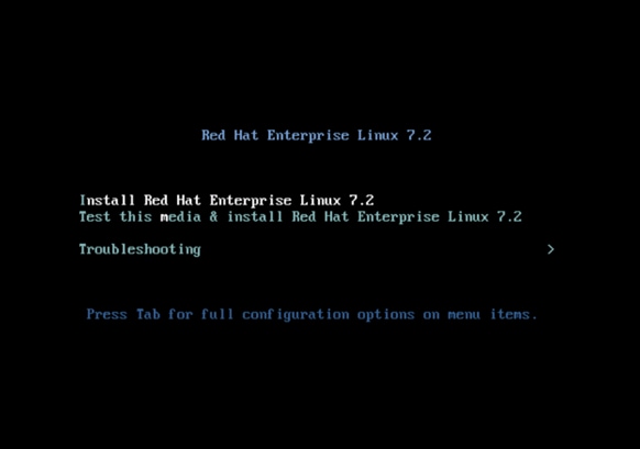
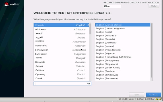
16. Skip the Media test and start the installation. Select language of installation and click Continue.
17. Select Date and time, which pops up another window as shown below:
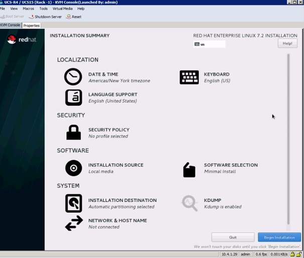
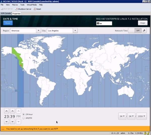
18. Select the location on the map, set the time and click Done.
19. Click Installation Destination.
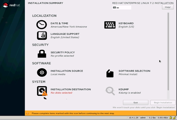
20. This opens a new window with the boot disks. Make the selection, and choose I will configure partitioning. Click Done.
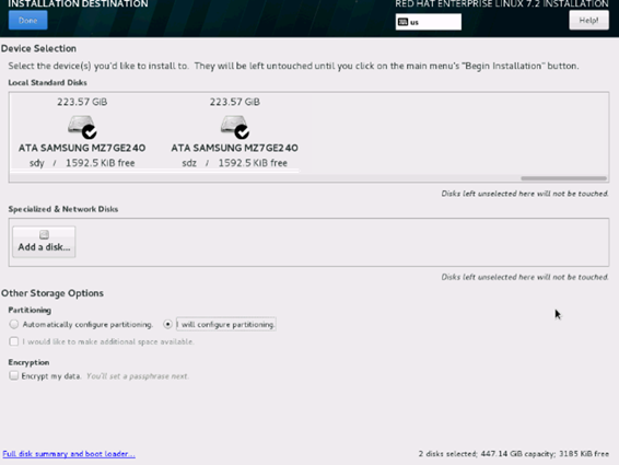
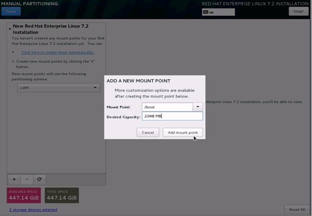
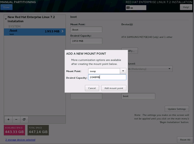
21. This opens the new window for creating the partitions. Click the + sign to add a new partition as shown below, boot partition of size 2048 MB.
22. Click Add Mount Point to add the partition.
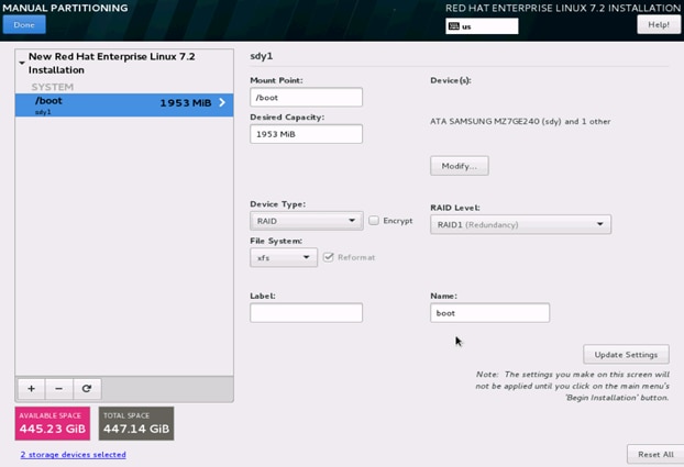
23. Change the Device type to RAID and make sure the RAID Level is RAID1 (Redundancy) and click Update Settings to save the changes.
24. Click the + sign to create the swap partition of size 2048 MB as shown below.
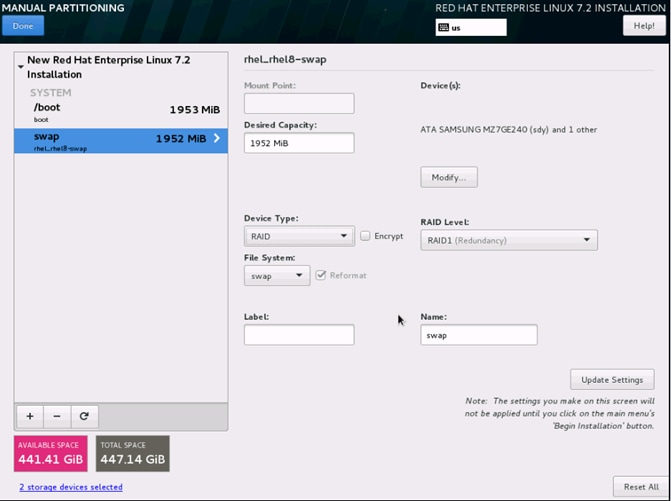
25. Change the Device type to RAID and RAID level to RAID1 (Redundancy) and click Update Settings.
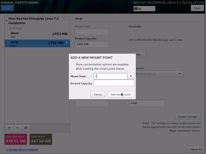
26. Click + to add the / partition. The size can be left empty so it uses the remaining capacity and click Add Mount point.
27. Change the Device type to RAID and RAID level to RAID1 (Redundancy). Click Update Settings.
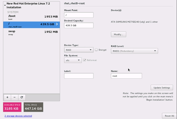
28. Click Done to go back to the main screen and continue the Installation.
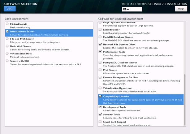
29. Click Software Selection.
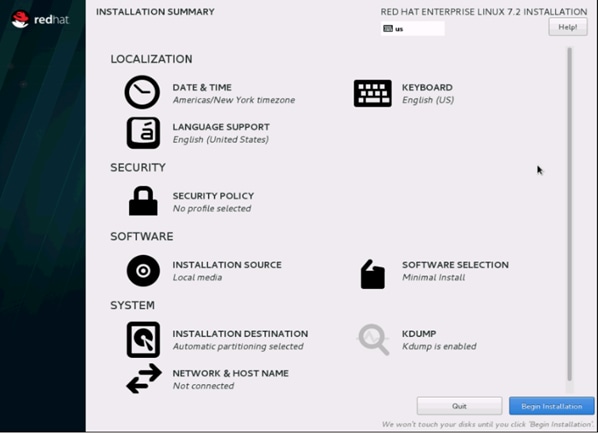
30. Select Infrastructure Server and select the Add-Ons as noted below. Click Done.
31. Click Network and Hostname and configure Hostname and Networking for the Host.

32. Type in the hostname as shown below.
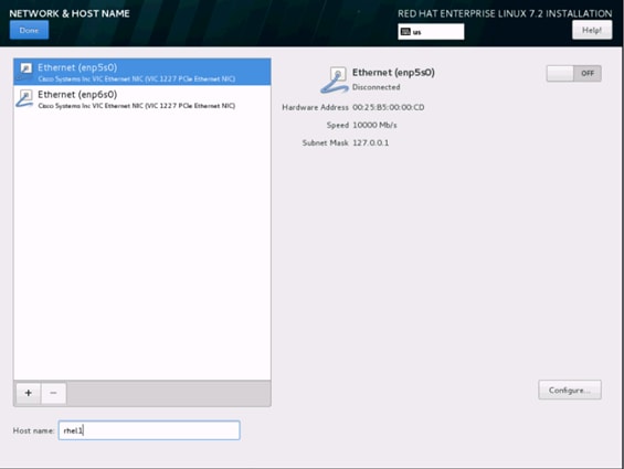
33. Click Configure to open the Network Connectivity window. Click IPV4Settings.
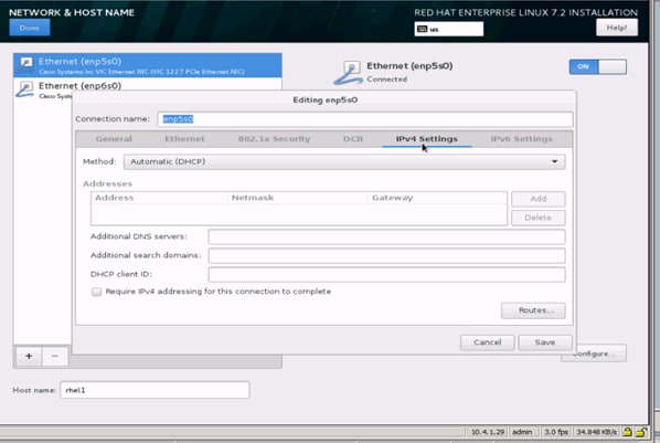
34. Change the Method to Manual and click Add to enter the IP Address, Netmask, and Gateway details.
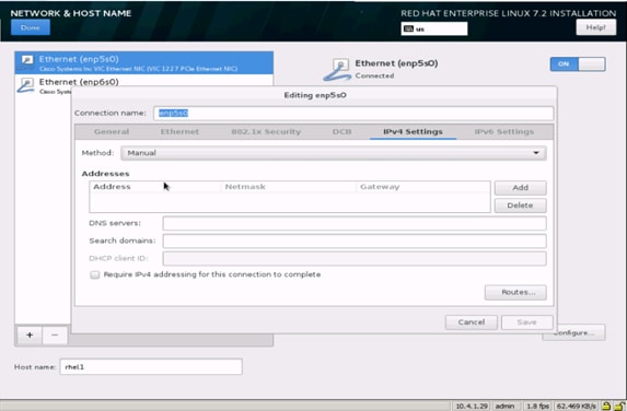
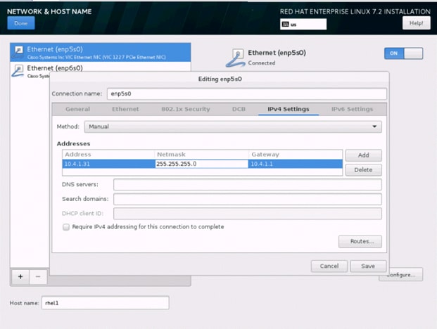
35. Click Save, update the hostname, and turn Ethernet ON. Click Done to return to the main menu.
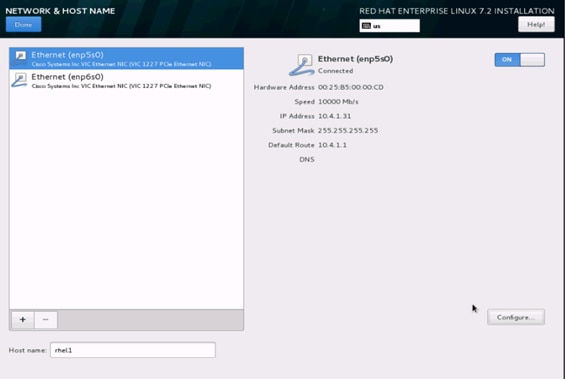
36. Click Begin Installation in the main menu.
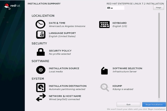
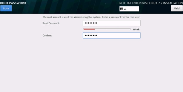
37. Select Root Password in the User Settings.
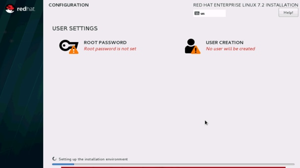
38. Enter the Root Password and click done.
39. When the installation is complete reboot the system.
40. Repeat steps 1 to 26 to install Red Hat Enterprise Linux 7.2 on Servers 2 through 22.
![]() Note: The OS installation and configuration of the nodes that is mentioned above can be automated through PXE boot or third party tools.
Note: The OS installation and configuration of the nodes that is mentioned above can be automated through PXE boot or third party tools.
The hostnames and their corresponding IP addresses are shown in Table 8.
Table 8 Hostnames and IP Addresses
| Hostname |
eth0 |
| rhel1 |
10.4.1.31 |
| rhel2 |
10.4.1.32 |
| rhel3 |
10.4.1.33 |
| rhel4 |
10.4.1.34 |
| rhel1 |
10.4.1.35 |
| rhel6 |
10.4.1.36 |
| rhel7 |
10.4.1.37 |
| rhel8 |
10.4.1.38 |
| rhel9 |
10.4.1.39 |
| rhel10 |
10.4.1.40 |
| rhel11 |
10.4.1.41 |
| rhel12 |
10.4.1.42 |
| rhel13 |
10.4.1.43 |
| rhel14 |
10.4.1.44 |
| rhel15 |
10.4.1.45 |
| rhel16 |
10.4.1.46 |
| rhel17 |
10.4.1.47 |
| rhel18 |
10.4.1.48 |
| rhel19 |
10.4.1.49 |
| metadata |
10.4.1.50 |
| va-compute |
10.4.1.51 |
| va-app-server |
10.4.1.52 |
| va-app-server |
x.x.x.x (external IP) |
![]() Note: va-app-server requires an external IP as it needs connectivity to the internet. If va-compute needs an external IP then add it here.
Note: va-app-server requires an external IP as it needs connectivity to the internet. If va-compute needs an external IP then add it here.
Post OS Install Configuration
Choose one of the nodes of the cluster or a separate node as the Admin Node for management such as CDH installation, cluster parallel shell, creating a local Red Hat repo and others. In this document, we use rhel1 for this purpose.
Setting Up Password-less Login
To manage all of the clusters nodes from the admin node, password-less login needs to be setup. It assists in automating common tasks with clustershell (clush, a cluster wide parallel shell), and shell-scripts without having to use passwords.
When Red Hat Linux is installed across all the nodes in the cluster, follow the steps below in order to enable password-less login across all the nodes.
1. Login to the Admin Node (rhel1).
#ssh 10.1.4.31
2. Run the ssh-keygen command to create both public and private keys on the admin node.

3. Download sshpass to the node connected to the internet and copy it to the admin node (rhel1) using the command:
wget ftp://195.220.108.108/linux/dag/redhat/el6/en/x86_64/dag/RPMS/sshpass-1.05-1.el6.rf.x86_64.rpm
scp sshpass-1.05-1.el6.x86_64.rpm rhel1:/root/
4. Log in to the admin node and Install the rpm using the command:
yum –y install sshpass-1.05-1.el6.x86_64.rpm
5. Create a file under /.ssh/config and enter the following lines:
vi ~/.ssh/config
ServerAliveInterval 99
StrictHostKeyChecking no
6. Run the following command from the admin node to copy the public key id_rsa.pub to all the nodes of the cluster. ssh-copy-id appends the keys to the remote-host’s .ssh/authorized_keys.
#for IP in {31..52}; do echo -n "$IP -> "; sshpass –p secret123 ssh-copy-id -i ~/.ssh/id_rsa.pub 10.4.1.$IP; done
Configuring /etc/hosts
Setup /etc/hosts on the Admin node; this is a pre-configuration to setup DNS as shown in this section.
To create the host file on the admin node, complete the following steps:
1. Populate the host file with IP addresses and corresponding hostnames on the Admin node (rhel1) and other nodes as follows:
2. On Admin Node (rhel1)
#vi /etc/hosts
127.0.0.1 localhost localhost.localdomain localhost4 \ localhost4.localdomain4
::1 localhost localhost.localdomain localhost6 \ localhost6.localdomain6
10.4.1.31 rhel1
10.4.1.32 rhel2
10.4.1.33 rhel3
10.4.1.34 rhel4
10.4.1.35 rhel5
10.4.1.36 rhel6
10.4.1.37 rhel7
10.4.1.38 rhel8
10.4.1.39 rhel9
10.4.1.40 rhel10
10.4.1.41 rhel11
10.4.1.42 rhel12
10.4.1.43 rhel13
10.4.1.44 rhel14
10.4.1.45 rhel15
10.4.1.46 rhel16
10.4.1.47 rhel17
10.4.1.48 rhel18
10.4.1.49 rhel19
10.4.1.50 metadata
10.4.1.51 va-compute
10.4.1.52 va-app-server
Creating a Red Hat Enterprise Linux (RHEL) 7.2 Local Repo
To create a repository using RHEL DVD or ISO on the admin node (in this deployment rhel1 is used for this purpose), create a directory with all the required RPMs, run the createrepo command and then publish the resulting repository.
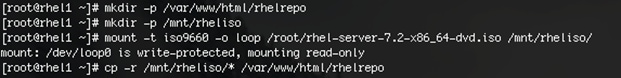
1. Log on to rhel1. Create a directory that would contain the repository.
#mkdir -p /var/www/html/rhelrepo
2. Copy the contents of the Red Hat DVD to /var/www/html/rhelrepo
3. Alternatively, if you have access to a Red Hat ISO Image, copy the ISO file to rhel1.
4. And login back to rhel1 and create the mount directory.
#scp rhel-server-7.2-x86_64-dvd.iso rhel1:/root/
#mkdir -p /mnt/rheliso
#mount -t iso9660 -o loop /root/rhel-server-7.2-x86_64-dvd.iso /mnt/rheliso/
5. Copy the contents of the ISO to the /var/www/html/rhelrepo directory.
#cp -r /mnt/rheliso/* /var/www/html/rhelrepo
6. Now on rhel1 create a .repo file to enable the use of the yum command.
#vi /var/www/html/rhelrepo/rheliso.repo
[rhel7.2]
name=Red Hat Enterprise Linux 7.2
baseurl=http://10.4.1.31/rhelrepo
gpgcheck=0
enabled=1
7. Now copy rheliso.repo file from /var/www/html/rhelrepo to /etc/yum.repos.d on rhel1.
#cp /var/www/html/rhelrepo/rheliso.repo /etc/yum.repos.d/
![]() Note: Based on this repo file yum requires httpd to be running on rhel1 for other nodes to access the repository.
Note: Based on this repo file yum requires httpd to be running on rhel1 for other nodes to access the repository.
8. To make use of repository files on rhel1 without httpd, edit the baseurl of repo file /etc/yum.repos.d/rheliso.repo to point repository location in the file system.
![]() Note: This step is needed to install software on Admin Node (rhel1) using the repo (such as httpd, create-repo, etc.)
Note: This step is needed to install software on Admin Node (rhel1) using the repo (such as httpd, create-repo, etc.)
#vi /etc/yum.repos.d/rheliso.repo
[rhel7.2]
name=Red Hat Enterprise Linux 7.2
baseurl=file:///var/www/html/rhelrepo
gpgcheck=0
enabled=1
Creating the Red Hat Repository Database
To create a Red Hat repository database, complete the following steps:
1. Install the createrepo package on admin node (rhel1). Use it to regenerate the repository database(s) for the local copy of the RHEL DVD contents.
#yum -y install createrepo

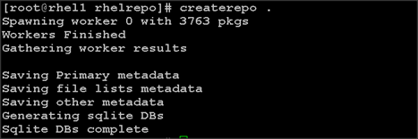
2. Run createrepo on the RHEL repository to create the repo database on admin node
#cd /var/www/html/rhelrepo
#createrepo .
Setting up ClusterShell
ClusterShell (or clush) is the cluster-wide shell that runs commands on several hosts in parallel. To setup the ClusterShell, complete the following steps:
1. From the system connected to the Internet download Cluster shell (clush) and install it on rhel1. Cluster shell is available from EPEL (Extra Packages for Enterprise Linux) repository.
#wget http://rpm.pbone.net/index.php3/stat/4/idpl/31529309/dir/redhat_el_7/com/clustershell-1.7-1.el7.noarch.rpm.html
#scp clustershell-1.7-1.el7.noarch.rpm rhel1:/root/
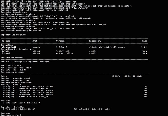
2. Login to rhel1 and install cluster shell.
3. #yum –y install clustershell-1.71.el7.noarch.rpm
4. Edit /etc/clustershell/groups.d/local.cfg file to include hostnames for all the nodes of the cluster. This set of hosts is taken when running clush with the ‘-a’ option.
5. For 64 node cluster as in our CVD, set groups file as follows,
#vi /etc/clustershell/groups.d/local.cfg
![]()
all: rhel[1-19],metadata,va-compute,va-app-server
![]() Note: For more information and documentation on ClusterShell, visit https://github.com/cea-hpc/clustershell/wiki/UserAndProgrammingGuide.
Note: For more information and documentation on ClusterShell, visit https://github.com/cea-hpc/clustershell/wiki/UserAndProgrammingGuide.
Installing httpd
Setting up RHEL repo on the admin node requires httpd. To set up RHEL repository on the admin node, complete the following steps:
1. Install httpd on the admin node to host repositories.
The Red Hat repository is hosted using HTTP on the admin node, this machine is accessible by all the hosts in the cluster.
#yum –y install httpd
2. Add ServerName and make the necessary changes to the server configuration file.
#vi /etc/httpd/conf/httpd.conf
ServerName 10.4.1.31:80

3. Start httpd
#service httpd start
#chkconfig httpd on
Set Up all Nodes to use the RHEL Repository
![]() Note: Based on this repo file yum requires httpd to be running on rhel1 for other nodes to access the repository.
Note: Based on this repo file yum requires httpd to be running on rhel1 for other nodes to access the repository.
4. Copy the rheliso.repo to all the nodes of the cluster.
#clush -a -b -x rhel1 -c /var/www/html/rhelrepo/rheliso.repo --dest=/etc/yum.repos.d/
5. Also copy the /etc/hosts file to all nodes.
#clush -a -b -c /etc/hosts
6. Purge the yum caches after this
#clush -a -B yum clean all
#clush –a –B yum repolist
Configuring DNS
This section details setting up DNS using dnsmasq as an example based on the /etc/hosts configuration setup in the earlier section.
To create the host file across all the nodes in the cluster, complete the following steps:
1. Disable Network manager on all nodes:
#clush -a -b service NetworkManager stop
#clush -a -b chkconfig NetworkManager off
2. Update /etc/resolv.conf file to point to Admin Node:
#vi /etc/resolv.conf
nameserver 10.4.1.31
![]() Note: This step is needed if setting up dnsmasq on Admin node. Otherwise this file should be updated with the correct nameserver.
Note: This step is needed if setting up dnsmasq on Admin node. Otherwise this file should be updated with the correct nameserver.
![]() Note: Alternatively #systemctl start NetworkManager.service can be used to start the service. #systemctl stop NetworkManager.service can be used to stop the service. Use #systemctl disable NetworkManager.service to stop a service from being automatically started at boot time.
Note: Alternatively #systemctl start NetworkManager.service can be used to start the service. #systemctl stop NetworkManager.service can be used to stop the service. Use #systemctl disable NetworkManager.service to stop a service from being automatically started at boot time.
3. Install and Start dnsmasq on Admin node:
#service dnsmasq start
#chkconfig dnsmasq on
4. Deploy /etc/resolv.conf from the admin node (rhel1) to all the nodes via the following clush command:
#clush -a -B -c /etc/resolv.conf
![]() Note: A clush copy without –dest copies to the same directory location as the source-file directory
Note: A clush copy without –dest copies to the same directory location as the source-file directory
5. Make sure DNS is working fine by running the following command on Admin node and any data-node
[root@rhel2 ~]# nslookup rhel1
Server: 10.4.1.31
Address: 10.4.1.31#53
Name: rhel1
Address: 10.4.1.31 ç
![]() Note: yum install –y bind-utils will need to be run for nslookup to utility to run.
Note: yum install –y bind-utils will need to be run for nslookup to utility to run.
Upgrading the Cisco Network Driver for VIC1387
To upgrade the Cisco Network Driver for VIC1387, complete the following steps:
The latest Cisco Network driver is required for performance and updates. The latest drivers can be downloaded from the link below:
1. In the ISO image, the required driver kmod-enic-2.3.0.31-rhel7u2.el7.x86_64.rpm can be located at \Linux\Network\Cisco\VIC\RHEL\RHEL7.2.
2. From a node connected to the Internet, download, extract and transfer kmod-enic-2.3.0.31-rhel7u2.el7.x86_64.rpm to rhel1 (admin node).
3. Install the rpm on all nodes of the cluster using the following clush commands. For this example the rpm is assumed to be in present working directory of rhel1.
4. [root@rhel1 ~]# clush -a -b -c kmod-enic-2.3.0.31-rhel7u2.el7.x86_64.rpm
5. [root@rhel1 ~]# clush -a -b "rpm –ivh kmod-enic-2.3.0.31-rhel7u2.el7.x86_64.rpm"
6. Make sure that the above installed version of kmod-enic driver is being used on all nodes by running the command "modinfo enic" on all nodes
[root@rhel1 ~]# clush -a -B "modinfo enic | head -5"
7. It is recommended to download the kmod-megaraid driver for higher performance, the RPM can be found in the same package at \Linux\Storage\LSI\12GSAS-HBA\RHEL\RHEL7.2
Installing xfsprogs
To install xfsprogs, complete the following steps:
1. From the admin node rhel1 run the command below to Install xfsprogs on all the nodes for xfs filesystem.
#clush -a -B yum -y install xfsprogs
![]()
NTP Configuration
The Network Time Protocol (NTP) is used to synchronize the time of all the nodes within the cluster. The Network Time Protocol daemon (ntpd) sets and maintains the system time of day in synchronism with the timeserver located in the admin node (rhel1). Configuring NTP is critical for any Hadoop Cluster. If server clocks in the cluster drift out of sync, serious problems will occur with HBase and other services.
#clush –a –b "yum –y install ntp"
![]() Note: Installing an internal NTP server keeps your cluster synchronized even when an outside NTP server is inaccessible.
Note: Installing an internal NTP server keeps your cluster synchronized even when an outside NTP server is inaccessible.
1. Configure /etc/ntp.conf on the admin node only with the following contents:
#vi /etc/ntp.conf
driftfile /var/lib/ntp/drift
restrict 127.0.0.1
restrict -6 ::1
server 127.127.1.0
fudge 127.127.1.0 stratum 10
includefile /etc/ntp/crypto/pw
keys /etc/ntp/keys
2. Create /root/ntp.conf on the admin node and copy it to all nodes:
#vi /root/ntp.conf
server 10.4.1.31
driftfile /var/lib/ntp/drift
restrict 127.0.0.1
restrict -6 ::1
includefile /etc/ntp/crypto/pw
keys /etc/ntp/keys
3. Copy ntp.conf file from the admin node to /etc of all the nodes by executing the following command: in the admin node (rhel1)
clush -a –b –c /root/ntp.conf --dest=/etc/ntp.conf
4. Run the following to synchronize the time and restart NTP daemon on all nodes:
#clush -a -b "service ntpd stop"
#clush -a -b "ntpdate rhel1"
#clush -a -b "service ntpd start"
5. Make sure restart of NTP daemon across reboots:
#clush –a –b "systemctl enable ntpd"
![]() Note: Alternatively, the new Chrony service can be installed, which is quicker to synchronize clocks in mobile and virtual systems.
Note: Alternatively, the new Chrony service can be installed, which is quicker to synchronize clocks in mobile and virtual systems.
6. Install the Chrony service:
# yum install -y chrony
7. Activate the Chrony service at boot:
# systemctl enable chronyd
8. Start the Chrony service:
# systemctl start chronyd
The Chrony configuration is in the /etc/chrony.conf file, configured similar to /etc/ntp.conf
Enabling Syslog
Syslog must be enabled on each node to preserve logs regarding killed processes or failed jobs. Modern versions such as syslog-ng and rsyslog are possible, making it more difficult to be sure that a syslog daemon is present. One of the following commands should suffice to confirm that the service is properly configured:
#clush -B -a rsyslogd –v
#clush -B -a service rsyslog status
Setting ulimit
On each node, ulimit -n specifies the number of inodes that can be opened simultaneously. With the default value of 1024, the system appears to be out of disk space and shows no inodes available. This value should be set to 64000 on every node.
To set the ulimit, complete the following steps:
![]() Note: Higher values are unlikely to result in an appreciable performance gain.
Note: Higher values are unlikely to result in an appreciable performance gain.
1. To set the ulimit on Redhat, edit /etc/security/limits.conf on admin node rhel1 and add the following lines:
root soft nofile 64000
root hard nofile 64000

2. Copy the /etc/security/limits.conf file from admin node (rhel1) to all the nodes using the following command:
#clush -a -b -c /etc/security/limits.conf --dest=/etc/security/
![]()
3. Check that the /etc/pam.d/su file contains the following settings:
#%PAM-1.0
auth sufficient pam_rootOK.so
# Uncomment the following line to implicitly trust users in the "wheel" group.
#auth sufficient pam_wheel.so trust use_uid
# Uncomment the following line to require a user to be in the "wheel" group.
#auth required pam_wheel.so use_uid
auth include system-auth
account sufficient pam_succeed_if.so uid = 0 use_uid quiet
account include system-auth
password include system-auth
session include system-auth
session optional pam_xauth.so
![]() Note: The ulimit values are applied on a new shell, running the command on a node on an earlier instance of a shell will show old values.
Note: The ulimit values are applied on a new shell, running the command on a node on an earlier instance of a shell will show old values.
Disabling SELinux
SELinux must be disabled during the install procedure and cluster setup. SELinux can be enabled after installation and while the cluster is running.
1. SELinux can be disabled by editing /etc/selinux/config and changing the SELINUX line to SELINUX=disabled. The following command will disable SELINUX on all nodes.
#clush -a -b "sed –i 's/SELINUX=enforcing/SELINUX=disabled/g' /etc/selinux/config"
![]()
#clush –a –b "setenforce 0"
![]() Note: The above command may fail if SELinux is already disabled.
Note: The above command may fail if SELinux is already disabled.
Reboot the machine, if needed for SELinux to be disabled incase it does not take effect. It can checked using
#clush –a –b sestatus
Set TCP Retries
Adjusting the tcp_retries parameter for the system network enables faster detection of failed nodes. Given the advanced networking features of UCS, this is a safe and recommended change (failures observed at the operating system layer are most likely serious rather than transitory). On each node, set the number of TCP retries to 5 can help detect unreachable nodes with less latency.
1. Edit the file /etc/sysctl.conf and on admin node rhel1 and add the following lines:
net.ipv4.tcp_retries2=5
2. Copy the /etc/sysctl.conf file from admin node (rhel1) to all the nodes using the following command:
#clush -a -b -c /etc/sysctl.conf --dest=/etc/
3. Load the settings from default sysctl file /etc/sysctl.conf by running.
#clush -B -a sysctl -p
Disabling the Linux Firewall
The default Linux firewall settings are far too restrictive for any Hadoop deployment. Since the UCS Big Data deployment will be in its own isolated network there is no need for that additional firewall.
#clush -a -b "firewall-cmd --zone=public --add-port=80/tcp --permanent"
#clush -a -b "firewall-cmd --reload"
#clush –a –b “systemctl disable firewalld”
Disable Swapping
To disable swapping, complete the following steps:
1. In order to reduce Swapping, run the following on all nodes. Variable vm.swappiness defines how often swap should be used, 60 is default.
#clush -a -b " echo 'vm.swappiness=1' >> /etc/sysctl.conf"
2. Load the settings from default sysctl file /etc/sysctl.conf.
#clush –a –b "sysctl –p"
Disable Transparent Huge Pages
To disable transparent Huge pages, complete the following steps:
1. The following commands must be run for every reboot, so copy this command to /etc/rc.local so they are executed automatically for every reboot.
Disabling Transparent Huge Pages (THP) reduces elevated CPU usage caused by THP:
#clush -a -b "echo never > /sys/kernel/mm/transparent_hugepage/enabled”
#clush -a -b "echo never > /sys/kernel/mm/transparent_hugepage/defrag"
2. On the Admin node, run the following commands:
#rm –f /root/thp_disable
#echo "echo never > /sys/kernel/mm/transparent_hugepage/enabled" >>
/root/thp_disable
#echo "echo never > /sys/kernel/mm/transparent_hugepage/defrag " >>
/root/thp_disable
3. Copy file to each node:
#clush –a –b –c /root/thp_disable
4. Append the content of file thp_disable to /etc/rc.local:
#clush -a -b “cat /root/thp_disable >> /etc/rc.local”
Disable IPv6 Defaults
1. Disable IPv6 as the addresses used are IPv4.
#clush -a -b "echo 'net.ipv6.conf.all.disable_ipv6 = 1' >> /etc/sysctl.conf"
#clush -a -b "echo 'net.ipv6.conf.default.disable_ipv6 = 1' >> /etc/sysctl.conf"
#clush -a -b "echo 'net.ipv6.conf.lo.disable_ipv6 = 1' >> /etc/sysctl.conf"
2. Load the settings from default sysctl file /etc/sysctl.conf.
#clush –a –b "sysctl –p"
Configuring the Filesystem
The following script will format and mount the available volumes on each node whether it is Namenode or Data node. OS boot partition is going to be skipped. All drives are going to be mounted based on their UUID as /data/disk1, /data/disk2, etc.
![]() Note: Verify that all nodes have the same number of drives by running this command: clush -a -b 'cat /proc/partitions | wc -l'
Note: Verify that all nodes have the same number of drives by running this command: clush -a -b 'cat /proc/partitions | wc -l'
1. On the Admin node, create a file containing the following script (below).
2. To create partition tables and file systems on the local disks supplied to each of the nodes, run the following script as the root user on each node.
![]() Note: The script assumes there are no partitions already existing on the data volumes. If there are partitions, delete them before running the script. This process is documented in the "Note" section at the end of the section.
Note: The script assumes there are no partitions already existing on the data volumes. If there are partitions, delete them before running the script. This process is documented in the "Note" section at the end of the section.
#vi /root/driveconf.sh
#!/bin/bash
#disks_count=`lsblk -id | grep sd | wc -l`
#if [ $disks_count -eq 8 ]; then
# echo "Found 8 disks"
#else
# echo "Found $disks_count disks. Expecting 8. Exiting.."
# exit 1
#fi
[[ "-x" == "${1}" ]] && set -x && set -v && shift 1
count=1
for X in /sys/class/scsi_host/host?/scan
do
echo '- - -' > ${X}
done
for X in /dev/sd?
do
echo "========"
echo $X
echo "========"
if [[ -b ${X} && `/sbin/parted -s ${X} print quit|/bin/grep -c boot` -ne 0
]]
then
echo "$X bootable - skipping."
continue
else
Y=${X##*/}1
echo "Formatting and Mounting Drive => ${X}"
/sbin/mkfs.xfs -f ${X}
(( $? )) && continue
#Identify UUID
UUID=`blkid ${X} | cut -d " " -f2 | cut -d "=" -f2 | sed 's/"//g'`
/bin/mkdir -p /data/disk${count}
(( $? )) && continue
echo "UUID of ${X} = ${UUID}, mounting ${X} using UUID on /data/disk${count}"
/bin/mount -t xfs -o inode64,noatime,nobarrier -U ${UUID} /data/disk${count}
(( $? )) && continue
echo "UUID=${UUID} /data/disk${count} xfs inode64,noatime,nobarrier 0 0" >> /etc/fstab
((count++))
fi
done
3. Run the following command to copy driveconf.sh to all the nodes:
#chmod 755 /root/driveconf.sh
#clush –a -B –c /root/driveconf.sh
4. Run the following command from the admin node to run the script across all data nodes:
#clush –a –B /root/driveconf.sh
5. Run the following from the admin node to list the partitions and mount points:
#clush –a -B df –h
#clush –a -B mount
#clush –a -B cat /etc/fstab
![]() Note: In-case there is a need to delete any partitions, it can be done so using the following.
Note: In-case there is a need to delete any partitions, it can be done so using the following.
6. Run the mount command (‘mount’) to identify which drive is mounted to which device /dev/sd<?>
7. umount the drive for which partition is to be deleted and run fdisk to delete as shown below.
![]() Note: Care should be taken not to delete the OS partition as this will wipe out the OS.
Note: Care should be taken not to delete the OS partition as this will wipe out the OS.
#mount
#umount /data/disk1 ç (disk1 shown as example)
#(echo d; echo w;) | sudo fdisk /dev/sd<?>
Cluster Verification
This section describes the steps to create the script cluster_verification.sh that helps to verify the CPU, memory, NIC, and storage adapter settings across the cluster on all nodes. This script also checks additional prerequisites such as NTP status, SELinux status, ulimit settings, JAVA_HOME settings and JDK version, IP address and hostname resolution, Linux version and firewall settings.
1. Create the script cluster_verification.sh as shown, on the Admin node (rhel1).
#vi cluster_verification.sh
#!/bin/bash
#shopt -s expand_aliases,
# Setting Color codes
green='\e[0;32m'
red='\e[0;31m'
NC='\e[0m' # No Color
echo -e "${green} === Cisco UCS Integrated Infrastructure for Big Data and Analytics \ Cluster Verification === ${NC}"
echo ""
echo ""
echo -e "${green} ==== System Information ==== ${NC}"
echo ""
echo ""
echo -e "${green}System ${NC}"
clush -a -B " `which dmidecode` |grep -A2 '^System Information'"
echo ""
echo ""
echo -e "${green}BIOS ${NC}"
clush -a -B " `which dmidecode` | grep -A3 '^BIOS I'"
echo ""
echo ""
echo -e "${green}Memory ${NC}"
clush -a -B "cat /proc/meminfo | grep -i ^memt | uniq"
echo ""
echo ""
echo -e "${green}Number of Dimms ${NC}"
clush -a -B "echo -n 'DIMM slots: '; dmidecode |grep -c \ '^[[:space:]]*Locator:'"
clush -a -B "echo -n 'DIMM count is: '; dmidecode | grep \Size| grep -c "MB""
clush -a -B " dmidecode | awk '/Memory Device$/,/^$/ {print}' |\grep -e '^Mem' -e Size: -e Speed: -e Part | sort -u | grep -v -e 'NO \ DIMM' -e 'No Module Installed' -e Unknown"
echo ""
echo ""
# probe for cpu info #
echo -e "${green}CPU ${NC}"
clush -a -B "grep '^model name' /proc/cpuinfo | sort -u"
echo ""
clush -a -B "`which lscpu` | grep -v -e op-mode -e ^Vendor -e family -e\ Model: -e Stepping: -e BogoMIPS -e Virtual -e ^Byte -e '^NUMA node(s)'"
echo ""
echo ""
# probe for nic info #
echo -e "${green}NIC ${NC}"
clush -a -B "ls /sys/class/net | grep ^enp | \xargs -l `which ethtool` | grep -e ^Settings -e Speed"
echo ""
clush -a -B "`which lspci` | grep -i ether"
echo ""
echo ""
# probe for disk info #
echo -e "${green}Storage ${NC}"
clush -a -B "echo 'Storage Controller: '; `which lspci` | grep -i -e \ raid -e storage -e lsi"
echo ""
clush -a -B "dmesg | grep -i raid | grep -i scsi"
echo ""
clush -a -B "lsblk -id | awk '{print \$1,\$4}'|sort | nl"
echo ""
echo ""
echo -e "${green} ================ Software ======================= ${NC}"
echo ""
echo ""
echo -e "${green}Linux Release ${NC}"
clush -a -B "cat /etc/*release | uniq"
echo ""
echo ""
echo -e "${green}Linux Version ${NC}"
clush -a -B "uname -srvm | fmt"
echo ""
echo ""
echo -e "${green}Date ${NC}"
clush -a -B date
echo ""
echo ""
echo -e "${green}NTP Status ${NC}"
clush -a -B "ntpstat 2>&1 | head -1"
echo ""
echo ""
echo -e "${green}SELINUX ${NC}"
clush -a -B "echo -n 'SElinux status: '; grep ^SELINUX= \/etc/selinux/config 2>&1"
echo ""
echo ""
clush -a -B "echo -n 'CPUspeed Service: '; cpupower frequency-info \ status 2>&1"
#clush -a -B "echo -n 'CPUspeed Service: '; `which chkconfig` --list \ cpuspeed 2>&1"
echo ""
echo ""
echo -e "${green}Java Version${NC}"
clush -a -B 'java -version 2>&1; echo JAVA_HOME is ${JAVA_HOME:-Not \ De-fined!}'
echo ""
echo ""
echo -e "${green}Hostname LoOKup${NC}"
clush -a -B " ip addr show"
echo ""
echo ""
echo -e "${green}Open File Limit${NC}"
clush -a -B 'echo -n "Open file limit(should be >32K): "; ulimit -n'
exit
2. Change permissions to executable.
chmod 755 cluster_verification.sh
3. Run the Cluster Verification tool from the admin node. This can be run before starting Hadoop to identify any discrepancies in Post OS Configuration between the servers or during troubleshooting of any cluster / Hadoop issues.
#./cluster_verification.sh
Installing Cloudera
Cloudera’s Distribution including Apache Hadoop (CDH) is an enterprise grade, hardened Hadoop distribution. CDH offers Apache Hadoop and several related projects into a single tested and certified product. It offers the latest innovations from the open source community with the testing and quality expected from enterprise quality software.
Prerequisites for CDH Installation
This section details the prerequisites for CDH installation such as setting up CDH Repo.
Cloudera Manager Repository
1. From a host connected to the Internet, download the Cloudera’s repositories as shown below and transfer it to the admin node.
#mkdir -p /tmp/clouderarepo/
2. Download Cloudera Manager Repository.
#cd /tmp/clouderarepo/
#wget http:/ /archive.cloudera.com/cm5/redhat/7/x86_64/cm/cloudera-manager.repo
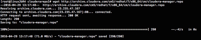
#reposync --config=./cloudera-manager.repo --repoid=cloudera-manager
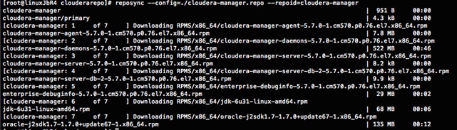
This downloads the Cloudera Manager RPMs needed for the Cloudera repository.
3. Run the following command to move the RPMs
4. Copy the repository directory to the admin node (rhel1)
#scp -r /tmp/clouderarepo/ rhel1:/var/www/html/
5. On admin node (rhel1) run create repo command.
#cd /var/www/html/clouderarepo/
#createrepo --baseurl http://10.4.1.31/clouderarepo/cloudera-manager/
/var/www/html/clouderarepo/cloudera-manager
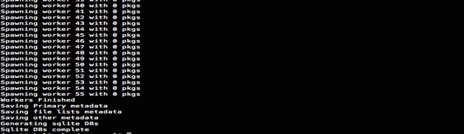
![]() Note: Visit http://10.4.1.31/clouderarepo/ to verify the files.
Note: Visit http://10.4.1.31/clouderarepo/ to verify the files.
![]() Note: that the previous step will download the latest Cloudera Manager rpm file. This CVD shows the 5.7 version of the Cloudera Manager.
Note: that the previous step will download the latest Cloudera Manager rpm file. This CVD shows the 5.7 version of the Cloudera Manager.
6. Create the Cloudera Manager repo file with following contents:
#vi /var/www/html/clouderarepo/cloudera-manager/cloudera-manager.repo
baseurl=http://10.4.1.31/clouderarepo/cloudera-manager/
enabled=1
7. Copy the file cloudera-manager.repo into /etc/yum.repos.d/ on the admin node to enable it to find the packages that are locally hosted.
#cp /var/www/html/clouderarepo/cloudera-manager/cloudera-manager.repo /etc/yum.repos.d/
8. From the admin node copy the repo files to /etc/yum.repos.d/ of all the nodes of the cluster.
9. #clush –w rhel[1-19] –B -c /etc/yum.repos.d/cloudera-manager.repo
Setting up the Local Parcels for CDH 5.7.0
1. From a host connected the internet, download the appropriate CDH 5.7.0 parcels that are meant for RHEL7.2 from the URL: http://archive.cloudera.com/cdh5/parcels/ and place them in the directory "/var/www/html/CDH5.7parcels" of the Admin node.
The following list shows the relevant files for RHEL7.2, as shown in the figure below:
· CDH-5.7.0-1.cdh5.7.0.p0.45-el7.parcel
· CDH-5.7.0-1.cdh5.7.0.p0.45-el7.parcel.sha1 and,
· manifest.json.
![]()
![]()

Downloading Parcels
1. From a host connected to the Internet, download the Cloudera’s parcels as shown below and transfer it to the admin node.
#mkdir -p /tmp/clouderarepo/CDH5.7parcel
2. Download parcels:
#cd /tmp/clouderarepo/CDH5.7parcels
#wget http://archive.cloudera.com/cdh5/parcels/5.7/CDH-5.7.0-1.cdh5.7.0.p0.45-el7.parcel
#wget http://archive.cloudera.com/cdh5/parcels/5.7/CDH-5.7.0-1.cdh5.7.0.p0.45-el7.parcel.sha1
#wget http://archive.cloudera.com/cdh5/parcels/5.7/manifest.json
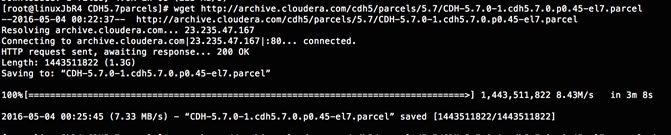

3. Now edit the /tmp/clouderarepo/CDH5.7parcels/manifest.json file and remove the scripts that are not meant for RHEL7.2. Below is that script which can be copy and pasted.
![]() Note: Please make sure the script starts and end with initial additional braces.
Note: Please make sure the script starts and end with initial additional braces.
{ {
"lastUpdated": 14594540550000,
"parcels": [
{
"parcelName": "CDH-5.7.0-1.cdh5.7.0.p0.45-el7.parcel",
"components": [
{
"pkg_version": "0.7.0+cdh5.7.0+0",
"pkg_release": "1.cdh5.7.0.p0.78",
"name": "bigtop-tomcat",
"version": "6.0.44-cdh5.7.0"
},
{
"pkg_version": "0.11.0+cdh5.7.0+93",
"pkg_release": "1.cdh5.7.0.p0.78",
"name": "crunch",
"version": "0.11.0-cdh5.7.0"
},
{
"pkg_version": "1.6.0+cdh5.7.0+37",
"pkg_release": "1.cdh5.7.0.p0.79",
"name": "flume-ng",
"version": "1.6.0-cdh5.7.0"
},
{
"pkg_version": "2.6.0+cdh5.7.0+1280",
"pkg_release": "1.cdh5.7.0.p0.92",
"name": "hadoop-0.20-mapreduce",
"version": "2.6.0-cdh5.7.0"
},
{
"pkg_version": "2.6.0+cdh5.7.0+1280",
"pkg_release": "1.cdh5.7.0.p0.92",
"name": "hadoop",
"version": "2.6.0-cdh5.7.0"
},
{
"pkg_version": "2.6.0+cdh5.7.0+1280",
"pkg_release": "1.cdh5.7.0.p0.92",
"name": "hadoop-hdfs",
"version": "2.6.0-cdh5.7.0"
},
{
"pkg_version": "2.6.0+cdh5.7.0+1280",
"pkg_release": "1.cdh5.7.0.p0.92",
"name": "hadoop-httpfs",
"version": "2.6.0-cdh5.7.0"
},
{
"pkg_version": "2.6.0+cdh5.7.0+1280",
"pkg_release": "1.cdh5.7.0.p0.92",
"name": "hadoop-kms",
"version": "2.6.0-cdh5.7.0"
},
{
"pkg_version": "2.6.0+cdh5.7.0+1280",
"pkg_release": "1.cdh5.7.0.p0.92",
"name": "hadoop-mapreduce",
"version": "2.6.0-cdh5.7.0"
},
{
"pkg_version": "2.6.0+cdh5.7.0+1280",
"pkg_release": "1.cdh5.7.0.p0.92",
"name": "hadoop-yarn",
"version": "2.6.0-cdh5.7.0"
},
{
"pkg_version": "1.2.0+cdh5.7.0+129",
"pkg_release": "1.cdh5.7.0.p0.88",
"name": "hbase",
"version": "1.2.0-cdh5.7.0"
},
{
"pkg_version": "1.5+cdh5.7.0+64",
"pkg_release": "1.cdh5.7.0.p0.78",
"name": "hbase-solr",
"version": "1.5-cdh5.7.0"
},
{
"pkg_version": "1.1.0+cdh5.7.0+522",
"pkg_release": "1.cdh5.7.0.p0.88",
"name": "hive",
"version": "1.1.0-cdh5.7.0"
},
{
"pkg_version": "1.1.0+cdh5.7.0+522",
"pkg_release": "1.cdh5.7.0.p0.88",
"name": "hive-hcatalog",
"version": "1.1.0-cdh5.7.0"
},
{
"pkg_version": "3.9.0+cdh5.7.0+1759",
"pkg_release": "1.cdh5.7.0.p0.86",
"name": "hue",
"version": "3.9.0-cdh5.7.0"
},
{
"pkg_version": "2.5.0+cdh5.7.0+0",
"pkg_release": "1.cdh5.7.0.p0.147",
"name": "impala",
"version": "2.5.0-cdh5.7.0"
},
{
"pkg_version": "1.0.0+cdh5.7.0+130",
"pkg_release": "1.cdh5.7.0.p0.77",
"name": "kite",
"version": "1.0.0-cdh5.7.0"
},
{
"pkg_version": "1.0.0+cdh5.7.0+0",
"pkg_release": "1.cdh5.7.0.p0.78",
"name": "llama",
"version": "1.0.0-cdh5.7.0"
},
{
"pkg_version": "0.9+cdh5.7.0+29",
"pkg_release": "1.cdh5.7.0.p0.79",
"name": "mahout",
"version": "0.9-cdh5.7.0"
},
{
"pkg_version": "4.1.0+cdh5.7.0+267",
"pkg_release": "1.cdh5.7.0.p0.78",
"name": "oozie",
"version": "4.1.0-cdh5.7.0"
},
{
"pkg_version": "1.5.0+cdh5.7.0+176",
"pkg_release": "1.cdh5.7.0.p0.78",
"name": "parquet",
"version": "1.5.0-cdh5.7.0"
},
{
"pkg_version": "0.12.0+cdh5.7.0+84",
"pkg_release": "1.cdh5.7.0.p0.77",
"name": "pig",
"version": "0.12.0-cdh5.7.0"
},
{
"pkg_version": "1.5.1+cdh5.7.0+184",
"pkg_release": "1.cdh5.7.0.p0.86",
"name": "sentry",
"version": "1.5.1-cdh5.7.0"
},
{
"pkg_version": "4.10.3+cdh5.7.0+389",
"pkg_release": "1.cdh5.7.0.p0.85",
"name": "solr",
"version": "4.10.3-cdh5.7.0"
},
{
"pkg_version": "1.6.0+cdh5.7.0+180",
"pkg_release": "1.cdh5.7.0.p0.84",
"name": "spark",
"version": "1.6.0-cdh5.7.0"
},
{
"pkg_version": "1.99.5+cdh5.7.0+38",
"pkg_release": "1.cdh5.7.0.p0.79",
"name": "sqoop2",
"version": "1.99.5-cdh5.7.0"
},
{
"pkg_version": "1.4.6+cdh5.7.0+56",
"pkg_release": "1.cdh5.7.0.p0.78",
"name": "sqoop",
"version": "1.4.6-cdh5.7.0"
},
{
"pkg_version": "0.9.0+cdh5.7.0+19",
"pkg_release": "1.cdh5.7.0.p0.78",
"name": "whirr",
"version": "0.9.0-cdh5.7.0"
},
{
"pkg_version": "3.4.5+cdh5.7.0+94",
"pkg_release": "1.cdh5.7.0.p0.80",
"name": "zookeeper",
"version": "3.4.5-cdh5.7.0"
}
],
"replaces": "IMPALA, SOLR, SPARK",
"hash": "6414b81d5ba5147abe67df63a55747fb47edb76e"
}
]
}
4. Copy /tmp/clouderarepo/CDH5.7parcels to the admin node (rhel1)
#scp -r /tmp/clouderarepo/CDH5.7parcels/ rhel1:/var/www/html/
5. Verify that these files are accessible by visiting the URL http://10.4.1.31/CDH5.7parcels/ in admin node.
Setting Up the MariaDB Database for Cloudera Manager
· Install the MariaDB Server
· Configure and Start the MariaDB Server
· Install the MariaDB/MySQL JDBC Driver
· Create Databases for Activity Monitor, Reports Manager, Hive Metastore Server, Sentry Server, Cloudera Navigator Audit Server, and Cloudera Navigator Metadata Server
Installing the MariaDB Server
To use a MariaDB database, complete the following steps:
1. In the admin node where Cloudera Manager will be installed, use the following command to install the mariadb/mysql server.
#yum –y install mariadb-server
2. To configure and start the MySQL Server, stop the MariaDB server if it is running.
#service mariadb stop
3. Move the old InnoDB log, if it exists.
4. Move files /var/lib/mysql/ib_logfile0 and /var/lib/mysql/ib_logfile1 out of/var/lib/mysql/ to a backup location.
#mv /var/lib/mysql/ib_logfile0 /root/ib_logfile0.bkp
#mv /var/lib/mysql/ib_logfile1 /root/ib_logfile1.bkp
5. Determine the location of the option file, my.cnf and edit/add following lines:
#vi /etc/my.cnf
[mysqld]
transaction-isolation = READ-COMMITTED
# InnoDB settings
innodb_flush_method = O_DIRECT
max_connections = 550
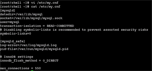
![]() Note: The max_connections need to be increased based on number of nodes and applications. Please follow the recommendations as mentioned in the Cloudera document http://www.cloudera.com/documentation/enterprise/latest/topics/install_cm_mariadb.html - install_cm_mariadb_config
Note: The max_connections need to be increased based on number of nodes and applications. Please follow the recommendations as mentioned in the Cloudera document http://www.cloudera.com/documentation/enterprise/latest/topics/install_cm_mariadb.html - install_cm_mariadb_config
6. Make sure MySQL Server starts at boot:
#systemctl enable mariadb.service
7. Start the MySQL Server:
#service mariadb start
8. Set the MySQL root password on admin node (rhel1)
#cd /usr/bin/
#mysql_secure_installation
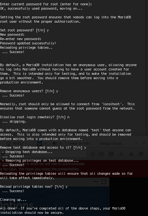
Installing the MySQL JDBC Driver
Install the JDBC driver on the Cloudera Manager Server host, as well as hosts which run the Activity Monitor, Reports Manager, Hive Metastore Server, Sentry Server, Cloudera Navigator Audit Server, and Cloudera Navigator Metadata Server roles.
1. From a host connected to the Internet, download the MySQL JDBC Driver and transfer it to the admin node. Download the MySQL JDBC driver from the URL http://www.mysql.com/downloads/connector/j/5.1.html
2. Copy mysql-connector-java-5.1.37.tar.gz to admin node(rhel1)
#scp mysql-connector-java-5.1.37.tar.gz rhel1:/root/
3. Log in to the admin node and extract the file:
#tar xzvf mysql-connector-java-5.1.37.tar.gz
4. Create the /usr/share/java/ directory on the admin node (rhel1)
#mkdir -p /usr/share/java/
5. Go to the mysql-connector-java-5.1.37 directory on the admin node (rhel1) and copy mysql-connector-java-5.1.37-bin.jar to /usr/share/java/
#cd mysql-connector-java-5.1.37
#cp mysql-connector-java-5.1.37-bin.jar /usr/share/java/mysql-connector-java.jar
Creating Databases for Activity Monitor, Reports Manager, Hive Metastore Server, Navigator Audit Server and Navigator Metadata Server
1. In the admin node Log into MySQL as the root user:
#mysql -u root –p
2. Enter the password that was supplied in step 8 above.
Enter password:
3. Create databases for the Activity Monitor, Reports Manager and Hive Metastore Server using the command below:
mysql> create database amon DEFAULT CHARACTER SET utf8;
mysql> create database rman DEFAULT CHARACTER SET utf8;
mysql> create database metastore DEFAULT CHARACTER SET utf8;
mysql> create database nav DEFAULT CHARACTER SET utf8;
mysql> create database navms DEFAULT CHARACTER SET utf8;
mysql> create database sentry DEFAULT CHARACTER SET utf8;
mysql> create database oozie DEFAULT CHARACTER SET utf8;
mysql> grant all on rman.*TO 'root'@'%' IDENTIFIED BY 'password';
mysql> grant all on metastore.*TO 'root'@'%' IDENTIFIED BY 'password';
mysql> grant all on amon.*TO 'root'@'%' IDENTIFIED BY 'password';
mysql> grant all on nav.*TO 'root'@'%' IDENTIFIED BY 'password';
mysql> grant all on navms.*TO 'root'@'%' IDENTIFIED BY 'password';
mysql> grant all on sentry.*TO 'root'@'%' IDENTIFIED BY 'password';
mysql> grant all privileges on oozie.* to root@'%' IDENTIFIED BY ‘password’;
mysql> grant all on rman.*TO 'rman'@'%' IDENTIFIED BY 'password';
mysql> grant all on metastore.*TO 'hive'@'%' IDENTIFIED BY 'password';
mysql> grant all on amon.*TO 'amon'@'%' IDENTIFIED BY 'password';
mysql> grant all on nav.*TO 'nav'@'%' IDENTIFIED BY 'password';
mysql> grant all on navms.*TO 'navms'@'%' IDENTIFIED BY 'password';
mysql> grant all on sentry.*TO 'root'@'%' IDENTIFIED BY 'password';
mysql> grant all privileges on oozie.* to oozie@'%' IDENTIFIED BY ‘password’;
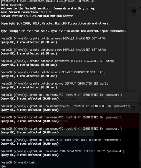
This section describes installing Cloudera Manager and using Cloudera Manager to install CDH 5.7.
Setting Up the Cloudera Manager Server Database
The Cloudera Manager Server Database stores information about service and host configurations.
Installing Cloudera Manager
Cloudera Manager, an end to end management application, is used to install and configure CDH. During CDH Installation, Cloudera Manager's Wizard will help to install Hadoop services on all nodes using the following procedure:
· Discovery of the cluster nodes
· Configure the Cloudera parcel or package repositories
· Install Hadoop, Cloudera Manager Agent (CMA) and Impala on all the cluster nodes
· Install the Oracle JDK if it is not already installed across all the cluster nodes
· Assign various services to nodes
· Start the Hadoop services.
To install Cloudera Manager, complete the following steps:
1. Update the repo files to point to local repository.
#rm -f /var/www/html/clouderarepo/*.repo
#cp /etc/yum.repos.d/c*.repo /var/www/html/clouderarepo/
2. Install the Oracle Java Development Kit on the Cloudera Manager Server host.
3. #yum install oracle-j2sdk1.7
4. Install the Cloudera Manager Server packages either on the host where the database is installed, or on a host that has access to the database.
#yum install cloudera-manager-daemons cloudera-manager-server
Preparing a Cloudera Manager Server External Database
1. Run the scm_prepare_database.sh script on the host where the Cloudera Manager Server package is installed (rhel1) admin node.
#cd /usr/share/cmf/schema
#./scm_prepare_database.sh mysql amon root <password>
#./scm_prepare_database.sh mysql rman root <password>
#./scm_prepare_database.sh mysql metastore root <password>
#./scm_prepare_database.sh mysql nav root <password>
#./scm_prepare_database.sh mysql navms root <password>
#./scm_prepare_database.sh mysql sentry root <password>
#./scm_prepare_database.sh mysql oozie root <password>
2. Verify the database connectivity using the following command.
[root@rhel1 ~]# mysql –u root –p
mysql> connect amon
mysql> connect rman
mysql> connect metastore
mysql> connect nav
mysql> connect navms
mysql> connect sentry
mysql> connect oozie
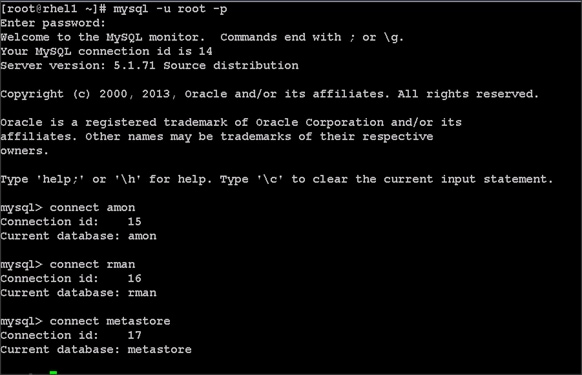
The MySQL External database setup is complete.
Starting the Cloudera Manager Server
1. Start the Coudera Manager Server:
#service cloudera-scm-server start
2. Access the Cloudera Manager using the URL, http://10.4.1.31:7180 to verify that the server is up.
3. Once the installation of Cloudera Manager is complete, install CDH5 using the Cloudera Manager Web interface.
Installing Cloudera Enterprise Data Hub (CDH5)
To install the Cloudera Enterprise Data Hub, complete the following steps:
1. Login to the Cloudera Manager. Enter "admin" for both the Username and Password fields.
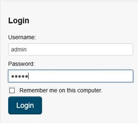
2. If you do not have a Cloudera license, select Cloudera Enterprise Data Hub Trial Edition. If you do have a Cloudera license, Click “Upload License” and select your license.
3. Based on requirement, choose appropriate Cloudera Editions for the Installation.
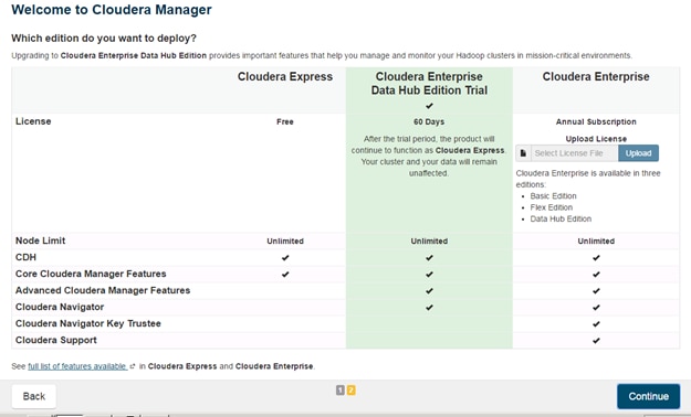
4. Click Continue on the confirmation page.
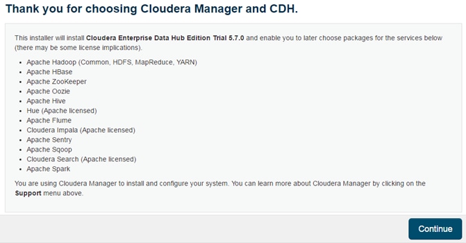
Edit the Cloudera Enterprise Parcel Settings to Use the CDH 5.7.0 Parcels
1. Open another tab in the same browser window and visit the URL: http://10.4.1.31:7180/cmf/parcel/status for modifying the parcel settings.
2. Click Configuration.
3. Click "-" to remove the entire remote repository URLs, and add the URL to the location where the the CDH 5.7.0 parcel is kept, for example http://10.4.1.31/CDH5.7parcels/.
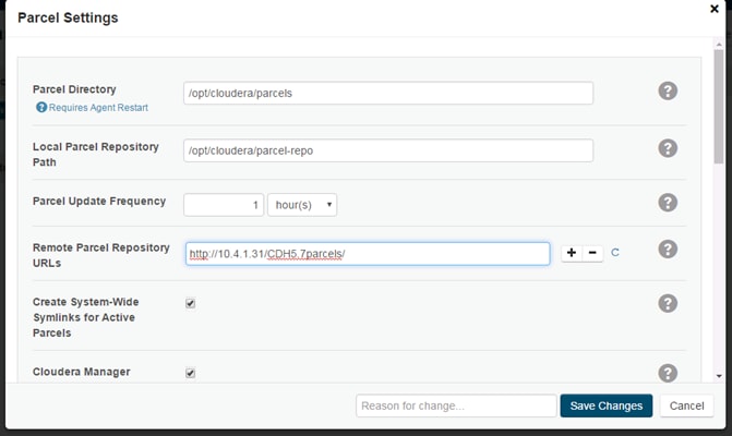
4. Click Save Changes to finish the configuration.
5. Navigate back to the Cloudera installation home page i.e. http://10.4.1.31:7180.
6. Click Continue on the confirmation page.

7. Specify the hosts that are part of the cluster using their IP addresses or hostname. The figure below shows use of a pattern to specify the IP addresses range.
10.4.1.[31-49] or rhel[1-19]
8. After the IP addresses or hostnames are entered, click Search.
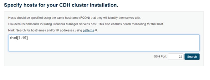
9. Cloudera Manager will "discover" the nodes in the cluster. Verify that all desired nodes have been found and selected for installation.
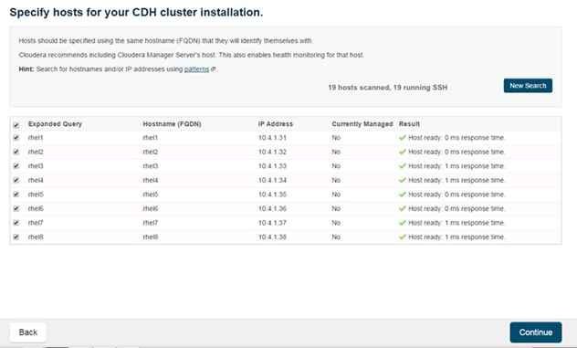
10. Click Continue.
11. For the method of installation, select the Use Parcels (Recommended) radio button.
12. For the CDH version, select the CDH5.7.0-1.cdh5.7.0.p0.45 radio button.
13. For the specific release of Cloudera Manager, select the Custom Repository radio button.
14. Enter the URL for the repository within the admin node. http://10.4.1.31/clouderarepo/cloudera-manager and click Continue.
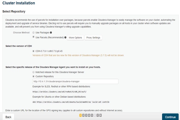
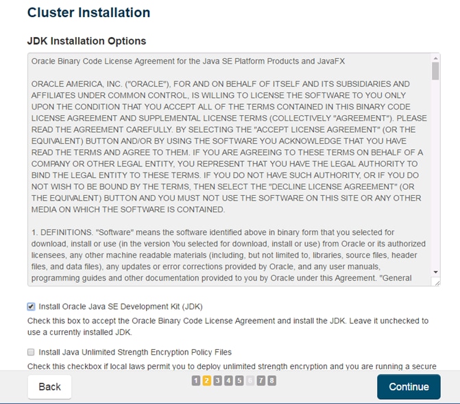
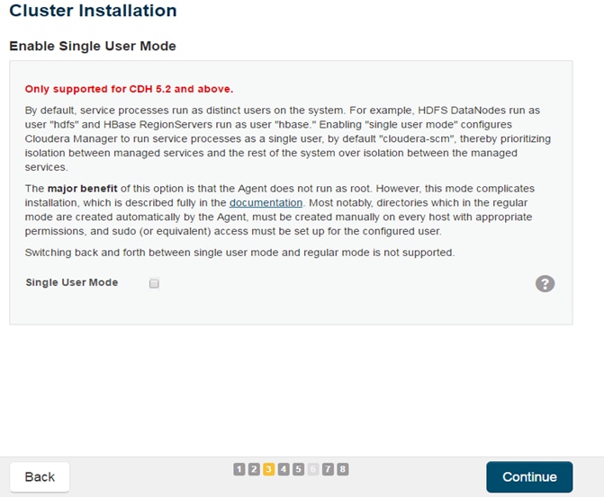
15. Provide SSH login credentials for the cluster and click Continue.
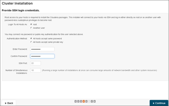
16. The installation using parcels begins.

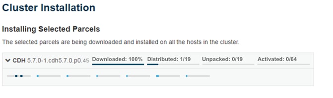
17. When the installation is completed successfully, click Continue to select the required services.
18. Wait for Cloudera Manager to inspect the hosts on which it has just performed the installation.
19. Review and verify the summary. Click Continue.
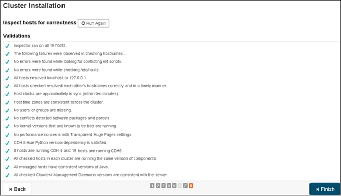
20. Select services that need to be started on the cluster.
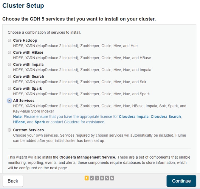
21. This is one of the critical steps in the installation. Inspect and customize the role assignments of all the nodes based on your requirements and click Continue.
22. Reconfigure the service assignment to match Table 7 below.
| Service Name |
Host |
| NameNode |
rhel1, rhel2 (HA) |
| HistoryServer |
rhel1 |
| JournalNodes |
rhel1,rhel2,rhel3 |
| ResourceManager |
rhel2, rhel3(HA) |
| Hue Server |
rhel2 |
| HiveMetastore Server |
rhel1 |
| HiveServer2 |
rhel2 |
| HBase Master |
rhel2 |
| Oozie Server |
rhel1 |
| ZooKeeper |
rhel1, rhel2, rhel3 |
| DataNode |
rhel4 to rhel19 |
| NodeManager |
rhel4 to rhel19 |
| RegionServer |
rhel4 to rhel19 |
| Sqoop Server |
rhel1 |
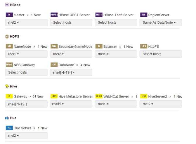
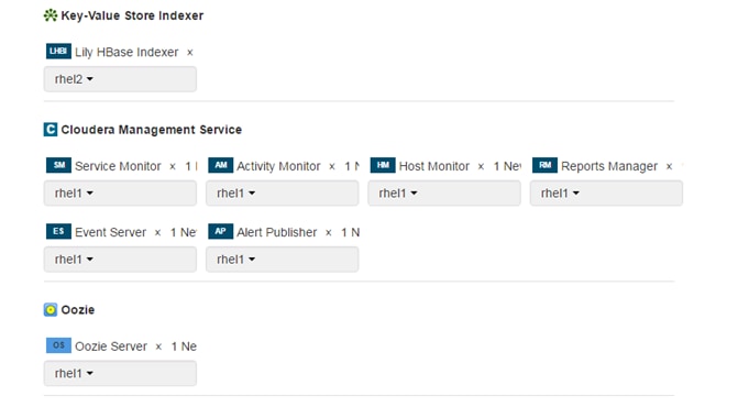
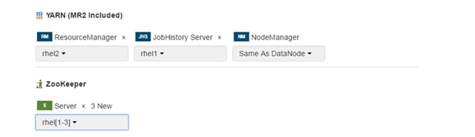
Setting up the Database
1. In the Database Host Name sections use port 3306 for TCP/IP because connection to the remote server always uses TCP/IP.
2. Enter the Database Name, username and password that were used during the database creation stage earlier in this document.
3. Click Test Connection to verify the connection and click Continue.
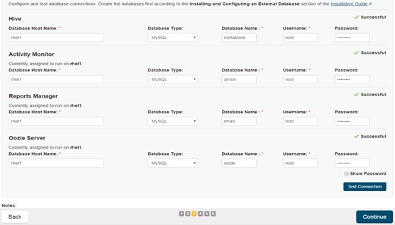
4. Review and customize the configuration changes based on your requirements.
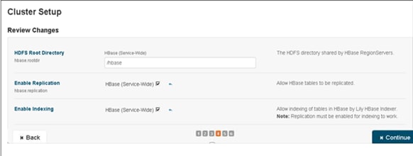
5. Click Continue to start running the cluster services.
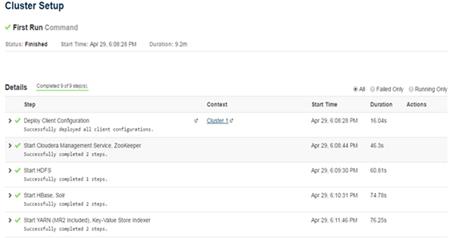
Starting the Cluster Services
1. Hadoop services are installed, configured and now running on all the nodes of the cluster. Click Finish to complete the installation.
Cloudera Manager now displays the status of all Hadoop services running on the cluster.
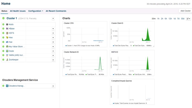
Scaling the Cluster
The role assignment recommendation above is for cluster with at least 64 servers and in High Availability (HA). For smaller cluster running without HA the recommendation is to dedicate one server for NameNode and a second server for secondary name node and YARN Resource Manager. For larger clusters larger than 64 nodes the recommendation is to dedicate one server each for name node, YARN Resource Manager and one more for running both NameNode (HA) and Resource Manager (HA) as in the table (no Secondary NameNode when in HA).
For production clusters it is recommended to set up NameNode and Resource manager in HA mode.
This implies that there will be at least 3 master nodes, running the NameNode, YARN Resource manager, the failover counter-part being designated to run on another node and a third node that would have similar capacity as the other two nodes.
All the three nodes will also need to run zookeeper and quorum journal node services. It is also recommended to have a minimum of 5 DataNodes in a cluster. Please refer to the next section for details on how to enable HA.
Enabling High Availability
![]() Note: Setting up HA is done after the Cloudera Installation is completed.
Note: Setting up HA is done after the Cloudera Installation is completed.
HDFS High Availability
The HDFS HA feature provides the option of running two NameNodes in the same cluster, in an Active/Passive configuration. These are referred to as the Active NameNode and the Standby NameNode. Unlike the Secondary NameNode, the Standby NameNode is a hot standby, allowing a fast failover to a new NameNode in the case that a machine crashes, or a graceful administrator-initiated failover for the purpose of planned maintenance. There cannot be more than two NameNodes.
For more information go to:
Setting Up HDFS HA
The Enable High Availability workflow leads through adding a second (standby) NameNode and configuring JournalNodes. During the workflow, Cloudera Manager creates a federated namespace.
1. Log in to the admin node (rhel1) and create the Edit directory for the JournalNode:
#clush -w rhel[1-3] mkdir -p /data/disk1/namenode-edits
#clush -w rhel[1-3] chmod 777 /data/disk1/namenode-edits
![]()
2. Log in to the Cloudera manager and go to the HDFS service.
3. In the top right corner Select Actions> Enable High Availability. A screen showing the hosts that are eligible to run a standby NameNode and the JournalNodes displays.
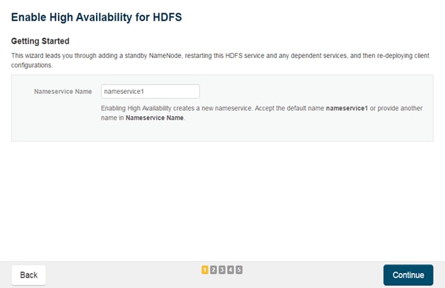
4. Specify a name for the nameservice or accept the default name nameservice1 and click Continue.
5. In the NameNode Hosts field, click Select a host. The host selection dialog displays.
6. Check the checkbox next to the hosts (rhel2) where the standby NameNode is to be set up and click OK.
![]() Note: The standby NameNode cannot be on the same host as the active NameNode, and the host that is chosen should have the same hardware configuration (RAM, disk space, number of cores, and so on) as the active NameNode.
Note: The standby NameNode cannot be on the same host as the active NameNode, and the host that is chosen should have the same hardware configuration (RAM, disk space, number of cores, and so on) as the active NameNode.
7. In the JournalNode Hosts field, click Select hosts. The host selection dialog displays.
8. Check the checkboxes next to an odd number of hosts (a minimum of three) to act as JournalNodes and click OK. Here we are using the same nodes as Zookeeper nodes.
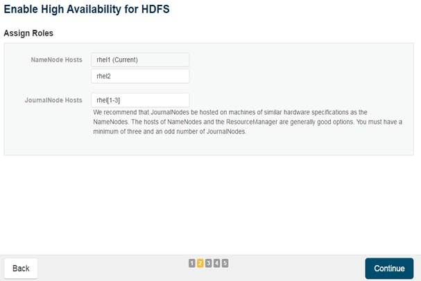
![]() Note: JournalNodes should be hosted on hosts with similar hardware specification as the NameNodes. It is recommended that each JournalNode is put on the same hosts as the active and standby NameNodes, and the third JournalNode on ResourceManager node.
Note: JournalNodes should be hosted on hosts with similar hardware specification as the NameNodes. It is recommended that each JournalNode is put on the same hosts as the active and standby NameNodes, and the third JournalNode on ResourceManager node.
9. Click Continue.
10. In the JournalNode Edits Directory property, enter a directory location created earlier in step 1 for the JournalNode edits directory into the fields for each JournalNode host.
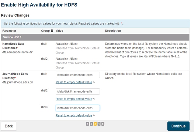
![]() Note: The directories specified should be empty, and must have the appropriate permissions.
Note: The directories specified should be empty, and must have the appropriate permissions.
Extra Options: Decide whether Cloudera Manager should clear existing data in ZooKeeper, Standby NameNode, and JournalNodes. If the directories are not empty (for example, re-enabling a previous HA configuration), Cloudera Manager will not automatically delete the contents—select to delete the contents by keeping the default checkbox selection. The recommended default is to clear the directories.
![]() Note: If chosen not to do so, the data should be in sync across the edits directories of the JournalNodes and should have the same version data as the NameNodes.
Note: If chosen not to do so, the data should be in sync across the edits directories of the JournalNodes and should have the same version data as the NameNodes.
11. Click Continue.
Cloudera Manager executes a set of commands that will stop the dependent services, delete, create, and configure roles and directories as appropriate, create a nameservice and failover controller, and restart the dependent services and deploy the new client configuration.
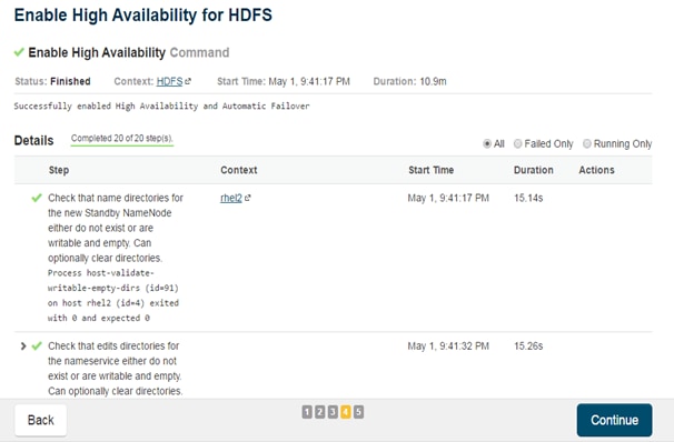
![]() Note: Formatting of name directory is expected to fail, if the directories are not empty.
Note: Formatting of name directory is expected to fail, if the directories are not empty.
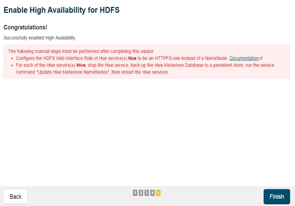
12. In the next screen additional steps are suggested by the Cloudera Manager to update the Hue and Hive metastore. Click Finish for the screen shown above.
![]() Note: The following subsections cover configuring Hue and Hive for HA as needed.
Note: The following subsections cover configuring Hue and Hive for HA as needed.
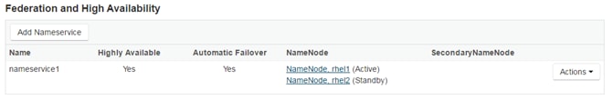
13. In the Cloudera Manager, Click on Home> HDFS> Instances to see Namenode in High Availability.
Configuring Hive Metastore to Use HDFS HA
To configure the Hive metastore to use HDFS high availability, complete the following steps:
1. Go the Hive service.
2. Select Actions> Stop.
3. Click Stop to confirm the command.
4. Back up the Hive metastore database (if any existing data is present).
5. Select Actions> Update Hive Metastore NameNodes and confirm the command.
6. Select Actions > Start.
7. Restart the Hue and Impala services if stopped prior to updating the Metastore.
Configuring Hue to Work with HDFS HA
1. Go to the HDFS service.
2. Click the Instances tab.
3. Click Add Role Instances.
4. Select the text box below the HttpFS field. The Select Hosts dialog displays.
5. Select the host on which to run the role and click OK.
6. Click Continue.
7. Check the checkbox next to the HttpFS role and select Actions for Selected> Start.
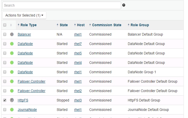
8. After the command has completed, go to the Hue service.
9. Click the Configuration tab.
10. Locate the HDFS Web Interface Role property or search for it by typing its name in the Search box.
11. Select the HttpFS role that was just created instead of the NameNode role, and save your changes.
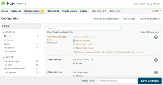
12. Restart the Hue service.
![]() Note: Refer to the Cloudera website: http://www.cloudera.com/documentation/enterprise/5-3-x/topics/cdh_hag_hdfs_ha_cdh_components_config.html - concept_rj1_hsq_bp for further details on setting up HA for other components like Impala, Oozie etc.
Note: Refer to the Cloudera website: http://www.cloudera.com/documentation/enterprise/5-3-x/topics/cdh_hag_hdfs_ha_cdh_components_config.html - concept_rj1_hsq_bp for further details on setting up HA for other components like Impala, Oozie etc.
YARN High Availability
The YARN Resource Manager (RM) is responsible for tracking the resources in a cluster and scheduling applications (for example, MapReduce jobs). Before CDH 5, the RM was a single point of failure in a YARN cluster. The RM High Availability (HA) feature adds redundancy in the form of an Active/Standby RM pair to remove this single point of failure. Furthermore, upon failover from the Standby RM to the Active, the applications can resume from their last check-pointed state; for example, completed map tasks in a MapReduce job are not re-run on a subsequent attempt. This allows events such the following to be handled without any significant performance effect on running applications.
· Unplanned events such as machine crashes.
· Planned maintenance events such as software or hardware upgrades on the machine running the Resource Manager
For more information please go to: http://www.cloudera.com/documentation/enterprise/latest/topics/cdh_hag_rm_ha_config.html - xd_583c10bfdbd326ba--43d5fd93-1410993f8c2--7f77
Setting up YARN HA
To set up YARN HA, complete the following steps:
1. Log into the Cloudera manager and go to the YARN service.
2. Select Actions > Enable High Availability.
A screenshot showing the hosts that are eligible to run a standby Resource Manager displays.
The host where the current Resource Manager is running is not available as a choice.
3. Select the host (rhel3) where the standby Resource Manager is to be installed, and click Continue.
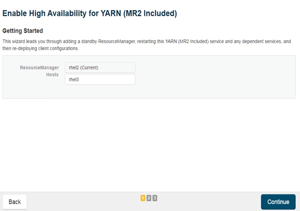
Cloudera Manager proceeds to execute a set of commands that stop the YARN service, add a standby Resource Manager, initialize the Resource Manager high availability state in ZooKeeper, restart YARN, and redeploy the relevant client configurations.
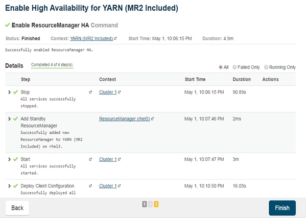
4. Click Finish when the installation is completed successfully.
Changing the Log Directory for All Applications
To change the default log from the /var prefix to /data/disk1, complete the following steps:
1. Log into the cloudera home page and click My Clusters.
2. From the configuration drop down menu select “All Log Directories.”
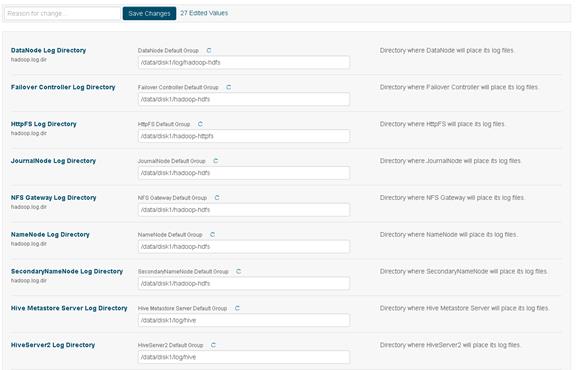
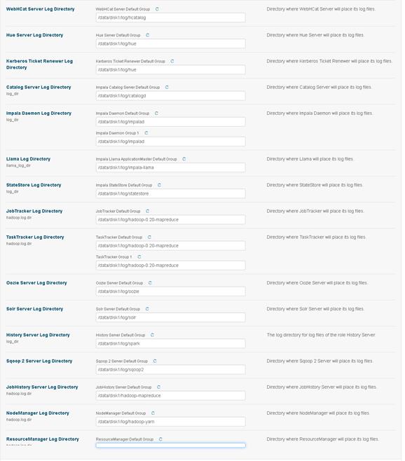
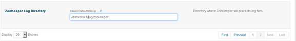
3. Click Save changes.
Create SAS Depot
SAS Depot is the SAS software package that needs to be downloaded through the SAS secured process.
Download SAS Depot
SAS License file, also called SAS Installation Data (SID) file, can be found under the folder “sid_files” in the SAS Depot. This file is in text format.
![]() Note: This process uses MobaXterm for Windows, which is pre-configured for X11 forwarding. This is the GUI shown in the steps below.
Note: This process uses MobaXterm for Windows, which is pre-configured for X11 forwarding. This is the GUI shown in the steps below.
On a separate node (Jump box / Edge node) connected to the internet, run the following commands:
1. Enable remote display parameter on Linux server “X11Forwarding yes” in /etc/ssh/sshd_config file as shown below.

2. Install X11* libraries and reconnect to session. Ignore if already installed.
3. Steps 1 and 2 above should also be performed on va-compute, va-app-server and metadata to allow X11 Forwarding.
4. Download SAS Download Manager tool from the link below and place the file on a separate node (Jump box / Edge node) connected to the internet:
https://support.sas.com/downloads/package.htm?pid=1991
5. Run the downloaded file.
6. # ./esdclient__94470__lax__xx__web__1
7. Choose the desired language.
8. Click OK.
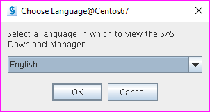
9. Provide the order number and SAS Installation Key and click Next to proceed with downloading.
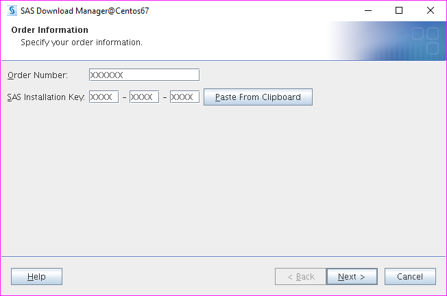
10. Verify the description and SAS Product list to confirm that you are downloading the correct depot. Click Next.
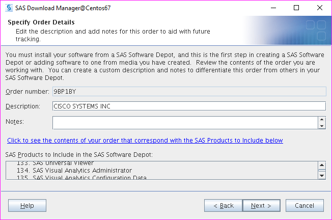
11. Select “Include complete order contents” and click Next.
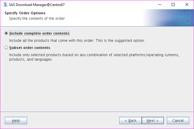
12. Select the target folder. Make sure it has enough space to hold the depot. Click Next.
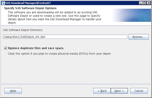
13. Verify the Depot information and click Download.
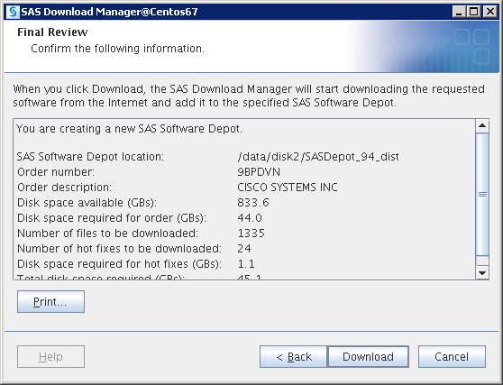
14. The Download starts and you can watch the progress.
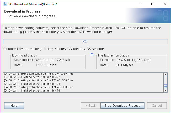
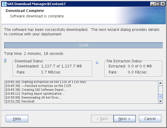
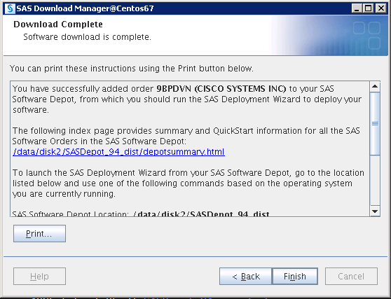
Run SAS Depot Checker
To run the SAS Depot Checker, complete the following steps:
![]() Note: SAS Depot Checker script does the validation for the downloaded depot and generates a report. This step is required to make sure the depot is valid before proceeding with the installation.
Note: SAS Depot Checker script does the validation for the downloaded depot and generates a report. This step is required to make sure the depot is valid before proceeding with the installation.
1. Copy the downloaded files (top-level directory=SASDepot_94_dist) to the /data/disk1 directory on va-app-server and also to the admin node (rhel1)
2. Go to depotchecker folder in the depot folder.
3. $ cd /data/disk1/SASDepot_94_dist/utilities/depotchecker
![]()
4. Run the depot checker script using below command.
$ ./SASDepotCheck.sh
5. Select language and click OK.
6. Navigate to folder which contains depot.

7. Check depot location and click Start.

8. Check the information that the wizard generates in the below window and make sure there are no errors. Click Finish.
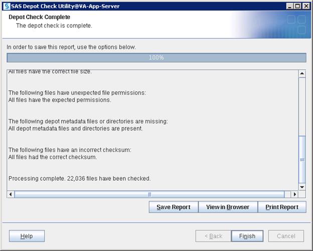
Plan.xml File
The plan.xml file is needed for the SAS Visual Analytics installation. Please contact a SAS sales support representative to get the installation plan file. The plan is delivered in the format ZQJ_plan.zip. Unzip and use the plan.xml in the extract as per instructions provided below. The plan.xml file is prepared either by SAS or by the vendor who is supposed to plan the architecture. This plan file will be changed from deployment to deployment depending on the architecture that is designed.
When you have the file copy to this location on the va-compute, va-app-server and metadata nodes: /data/disk1/sasdepot/SASDepot_94_dist/plan_files/
#cp plan.xml /data/disk1/sasdepot/SASDepot_94_dist/plan_files/
Setting Prerequisites for SAS Visual Analytics
This section details the prerequisites for the SAS VA installation.
Create Linux Group
To create the Linux group, complete the following steps:
1. Make sure clush is working fine by running below command.
# clush -a -b pwd

2. Create “sasgrp” group on all servers using clush with a unique gid(1005 in below command).
# clush -a -b "groupadd -g 1005 sasgrp"
![]()
3. Checking group on all servers.
# clush -a -b "grep sasgrp /etc/group"

Create /etc/gridhosts
To create /etc/gridhosts, complete the following steps:
1. Create a file /etc/gridhosts and list all the LASR nodes hostnames in the file.
2. Make sure the LASR Root node is at first place in the list.
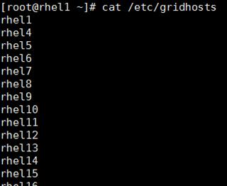
Create Linux Users
To create user SAS to install the software on all servers, complete the following steps:
1. Create a user named “sas” with unique UID on all servers (for example, 1023), and add into sasgrp group.
# clush -a -b "useradd -u 1023 -g 1005 sas"
![]()
2. Checking the user created and have same UID on all the servers in cluster.
# clush -a -b "grep 1023 /etc/passwd"
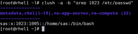
Create User sasdemo on Metadata, Compute, and Root Node Server
1. Create a user named “sasdemo” (not required on LASR nodes) and add into sasgrp group
# useradd -u 1024 -g 1005 sasdemo
![]()
2. Check the user created on root, compute and metadata nodes (root shown)
# grep sasdemo /etc/passwd
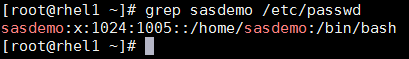
Create User sassrv on Metadata, Compute, and Root Node Server
1. Create a user named “sassrv” (not required on LASR servers) and add into sasgrp group
# useradd -u 1025 -g 1005 sassrv
![]()
2. Check the user created on root, compute and metadata nodes (root shown)
# grep sassrv /etc/passwd
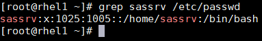
Create User "lasradm" for LASR Administration on all Servers
1. Create a user named “lasradm” with unique UID on all servers (, 1026), and add into sasgrp group
# clush -a -b "useradd -u 1026 -g 1005 lasradm"
![]()
2. Check the created user.
# clush -a -b "grep lasradm /etc/passwd"
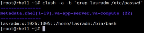
Password-less Authentication
To enable password-less authentication for a “sas” user, complete the following steps:
1. Generate public key on LASR Root server.
$ ssh-keygen
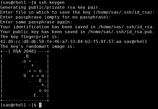
2. Run the following command from the admin node to copy the public key id_rsa.pub to all the nodes of the cluster. ssh-copy-id appends the keys to the remote-host’s .ssh/authorized_keys.
$ for IP in {31..49}; do echo -n "$IP -> "; ssh-copy-id -i ~/.ssh/id_rsa.pub 10.4.1.$IP; done
3. To check the password-less authentication, run the following command from rhel1. A successful result will list all the hosts in order in /etc/gridhosts.
$ for hst in `cat /etc/gridhosts`; do ssh $hst hostname ; done
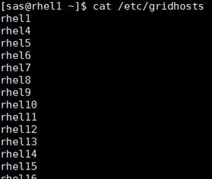
Enable Password-less Authentication for “lasradm” User
1. Logon to the Root Server and generate both public and private keys by running the command “ssh-keygen”.
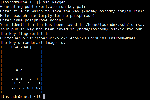
2. Then run the following command from the admin node to copy the public key id_rsa.pub to all the nodes of the cluster. ssh-copy-id appends the keys to the remote-host’s .ssh/authorized_keys.
$ for IP in {31..49}; do echo -n "$IP -> "; ssh-copy-id -i ~/.ssh/id_rsa.pub 10.4.1.$IP; done
3. To check the password-less authentication, run the below command from rhel1. Successful result should list out all the hosts as per the order in /etc/gridhosts.
$ for hst in `cat /etc/gridhosts`; do ssh $hst hostname ; done
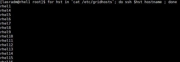
Install Libraries
To install the remaining libraries, run the following command.
1. From the admin node (rhel1) run the following command:
# clush -a -b "yum install -y x11* xauth firefox python compat-glibc libpng12 lsof at numactl glibc libpng ntp nfs-utils.x86_64 nfs-utils-lib.x86_64 compat-libstdc++-33 strace apr ksh wget mlocate libuuid libSM libXrender fontconfig libstdc++ zlib"
![]()
Set Ulimit
To set Ulimit, complete the following steps:
1. Go to LASR Root Node and backup the limits.conf file using the following command.
# cp -p /etc/security/limits.conf /etc/security/limits.conf_original
![]()
2. Add the following lines to the end of the file.
vi /etc/security/limits.conf
* hard nofile 350000
* soft nofile 350000
* hard nproc 100000
* soft nproc 100000
* hard stack 10240
* soft stack 10240
3. The value of nproc needs to be changed from the default value of 1096 to 10000 in the file “/etc/security/limits.d/20-nproc.conf”.
vi /etc/security/limits.d/20-nproc.conf
![]()
The new default value is shown below.
![]()
High Performance Analytics Infrastructure Implementation
SAS High Performance Computing Management Console Installation
The SAS High-Performance Computing Management Console is used for managing high-performance computing environments. The console assists with managing operating system user IDs and groups. The console can also be used to perform administration of SSH lockouts and assist with managing CPU and memory resources. SASHPCMC installation provides two commands named “simsh” and “simcp” which assists you to install further SAS components such as “TKGrid” and “Hadoop configuration to SAS” easily in all servers.
To install, complete the following steps:
1. Logon to rhel1, copy the sashpcmc-2.8.x86_64.rpm file from the SASDepot directory to /tmp.
# cp SASDepot_94_dist/standalone_installs/SAS_High-Performance_Computing_Management_Console/2_8/Linux_for_x64/sashpcmc-2.8.x86_64.rpm /tmp
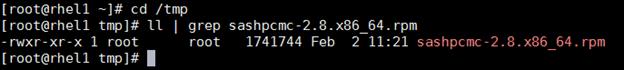
2. Create a directory for hpcmc.
#mkdir –p /opt/sas/hpcmc
3. Go to /tmp directory and run the rpm file using the following command. This will install the rpm into the /opt/sas/hpcmc directory.
# rpm -ivh --prefix=/opt/sas/hpcmc sashpcmc-2.8.x86_64.rpm
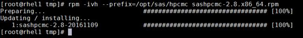
4. Go to /opt/sas/hpcmc/webmin/utilbin.
# cd /opt/sas/hpcmc/webmin/utilbin
![]()
5. Run the setup script.
a. ./setup
b. Enter username as hpcadmin
c. Enter “yes” when it prompts for local account setup.
d. Enter password
e. Enter password again for confirming the password
f. Enter “no” for Use SSL.
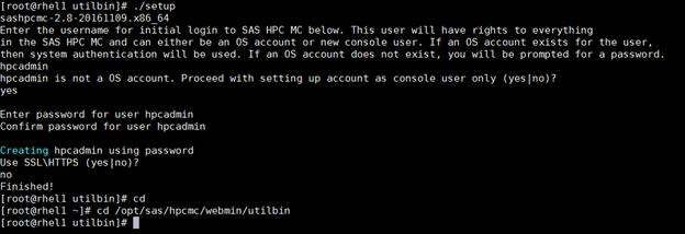
6. Change the port used by HPCMC (10020) since it is used by the Hadoop service.
a. Go to /opt/sas/hpcmc/webmin/etc
# cd /opt/sas/hpcmc/webmin/etc
![]()
b. Backup the file miniserv.conf.
# cp miniserv.conf miniserv.conf_original
![]()
c. Change “port” and “listen” values from 10020 to 10021 in miniserv.conf file.
# vi miniserv.conf
Old values:
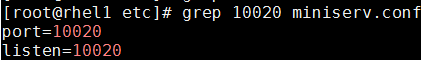
New values:
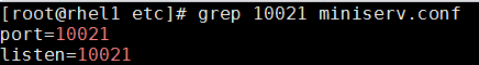
7. Start SASHPCMC service.
# service sashpcmc start
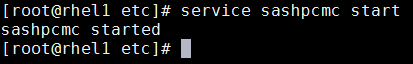
8. Check the status for confirmation.
# service sashpcmc status
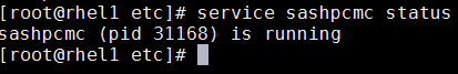
9. Open your browser and go to: http://10.4.1.31:10021 and verify the console is available. Login with the user created earlier: hpcadmin.

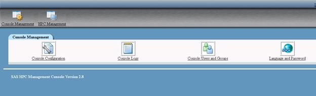
10. Validate the simsh command on the admin server. The “simsh” command is installed as part of the HPCMC installation. It can run any OS command on all LASR servers simultaneously.
# /opt/sas/hpcmc/webmin/utilbin/simsh hostname
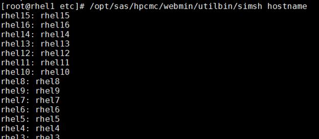
11. Verify simcp command on the admin server. “simcp” command is installed as part of the HPCMC installation. It executes a copy command on all LASR servers simultaneously.
# touch samplefile
# /opt/sas/hpcmc/webmin/utilbin/simcp /tmp/samplefile /tmp/samplefile_copy
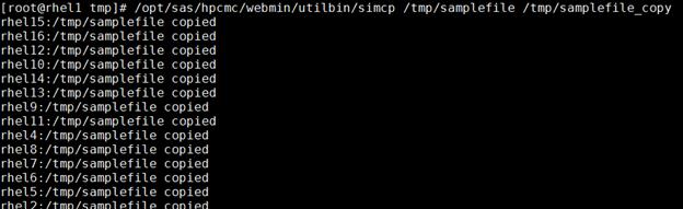
12. Update the PATH environment variable for user “sas” so simsh and simcp commands are in the path. This is required for the next steps in the installation.
a. Logon to LASR root with “sas” user.
b. Run “$ echo 'export PATH=$PATH:/opt/sas/hpcmc/webmin/utilbin' >> ~/.bash_profile”
![]()
c. Verify the updated PATH by logging out, logging back in and running simsh and simcp without a path name.
Install TKGrid and TKTGDat
The combination of TKGrid and TKTGDat is the High Performance Analytics Environment software that is required for Distributed Visual Analytics deployment which assists in distributing load across the cluster.
To install the TKGrid and TKTGDat, complete the following steps:
1. Login to the LASR Root node, rhel1, as the sas user.
2. Create directory for TKGrid on all LASR nodes using simsh command.
$ simsh mkdir /opt/sas/TKGrid_3.5
![]()
3. Check whether directories are created.
$ simsh ls -ld /opt/sas/TKGrid_3.5
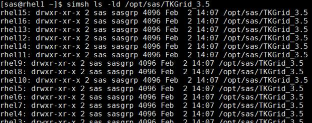
4. Copy the TKGrid_Linux_x86_64.sh file from the SAS depot directory to /tmp.
# cp SASDepot_94_dist/standalone_installs/SAS_High-Performance_Node_Installation/3_5/Linux_for_x64/TKGrid_Linux_x86_64.sh /tmp
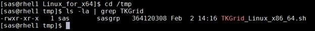
5. Go to the TKGrid installation folder.
$ cd /opt/sas/TKGrid_3.5/
![]()
6. Install TKGrid, by running the recently copied script.
$ /tmp/TKGrid_Linux_x86_64.sh
![]()
a. Script starts
b. Allow replication on each node by giving option “n”.
![]()
c. Press ENTER for the next 4 options since you do not have to enter anything.
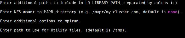
d. Enter your installed Hadoop path.
![]()
e. Enter ‘n’ for Force Root Rank to run on headnode.
![]()
f. Enter file “/etc/gridhosts” for machine list.
![]()
g. Press ENTER for maximum runtime for grid jobs and provide value 022 for UMASK value.
UMASK value is the permissions pattern that will be applied on the binaries of TKGrid and 022 is the recommended permission pattern. These permissions will be set on the binaries during installation across all HPAE nodes.
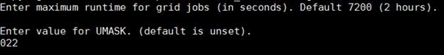
h. Enter “YES” to perform copy of installation to all LASR nodes.
![]()
The installation starts:
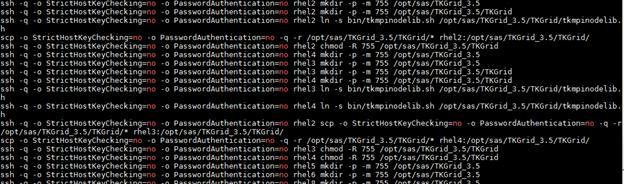
7. Copy TKTGDat.sh file from the SAS depot directory to /tmp.
$ cp SASDepot_94_dist/standalone_installs/SAS_High-Performance_Node_Installation/3_5/Linux_for_x64/TKTGDat.sh /tmp
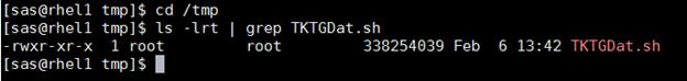
8. Go to the TKGrid installation folder.
$ cd /opt/sas/TKGrid_3.5/
![]()
9. Install TKGrid, by running the recently copied script.
$ /tmp/TKTGDat.sh
![]()
The script starts:
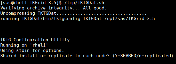
a. Allow replication on each node by entering “n”.
![]()
b. Enter the full path of machines list as “/etc/gridhosts”.
![]()
c. Copy the installation to all nodes by entering YES.
![]()
The installation starts:
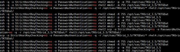
10. Create symbolic links on all LASR nodes.
$ simsh ln -s /opt/sas/TKGrid_3.5/TKGrid /opt/sas/TKGrid
$ simsh ln -s /opt/sas/TKGrid_3.5/TKTGDat /opt/sas/TKTGDat
![]()
![]()
11. Connect to rhel1 (admin / root node) and go to the /bin directory and run the following commands to set environment variables.
$ echo 'export TKPATH=/opt/sas/TKGrid/lib:/opt/sas/TKGrid/bin' >> ~/.bash_profile
$ echo 'export GRIDRSHCOMMAND=/opt/sas/TKGrid_3.5/TKGrid/bin/ssh.sh' >> ~/.bash_profile
$ echo 'export GRIDHOST=rhel1' >> ~/.bash_profile
$ echo 'export GRIDINSTALLLOC=/opt/sas/TKGrid/' >> ~/.bash_profile

12. Run the below script for validating TKGrid graphically.
$ /opt/sas/TKGrid/bin/gridmon.sh
![]()
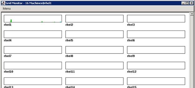
SAS Metadata Tier Installation
The Metadata Tier is basically a tier that contains Metadata Server. SAS Metadata Server is a service that maintains metadata repository which contains the data about all the configuration, users, groups and other application components.
Installation
To deploy all the binaries of the selected SAS tier, complete the following steps:
1. Login to metadata server as sas user, and run the command to start the installation.
$ cd SASDepot_94_dist
$ ./setup.sh &
![]()
2. Select “Install SAS software”. Click Next.

3. Navigate to the SAS Home directory where you want to deploy the SAS metadata binaries.
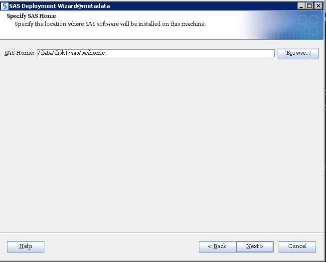
4. Select “Perform a Planned Deployment” and “Install SAS Software”.
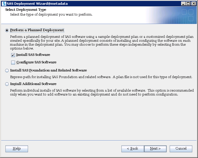
5. Place the plan.xml file in some accessible location on server and navigate to the file. Click Next.
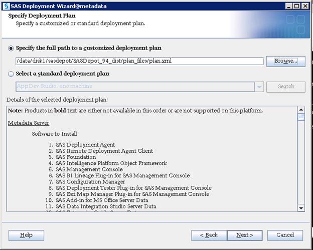
6. Select “Metadata Server” from the drop-down list.
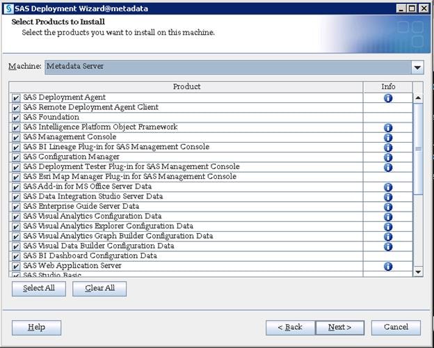
7. Navigate to the license SID file which is located in the “sid_files” folder in your depot. The license file will be in text format.
8. Check the license information before clicking Next.

9. Select the desired languages you would like to install for the products listed below.
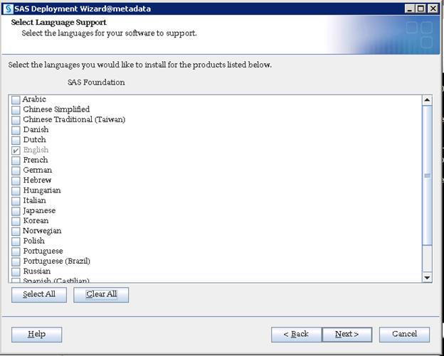
10. Select the desired language locale from the drop-down list and click Next.
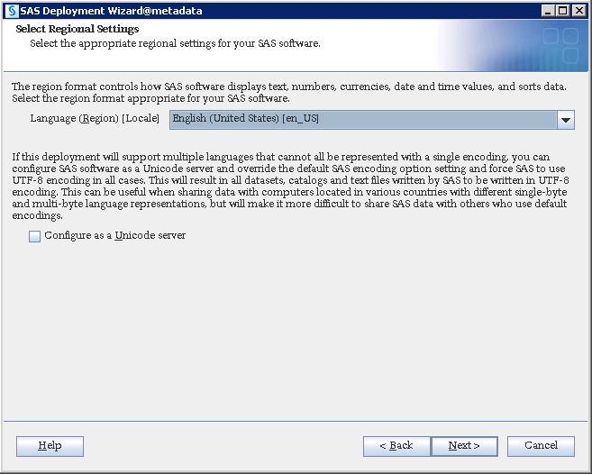
11. Select the products to configure SAS/Access interface and click Next.
![]() Note: This is required if you are going to use any of the given database types as your data sources. Else, you can leave them blank and go forward which will not give further screens related to SAS/Access configuration of these database types.
Note: This is required if you are going to use any of the given database types as your data sources. Else, you can leave them blank and go forward which will not give further screens related to SAS/Access configuration of these database types.
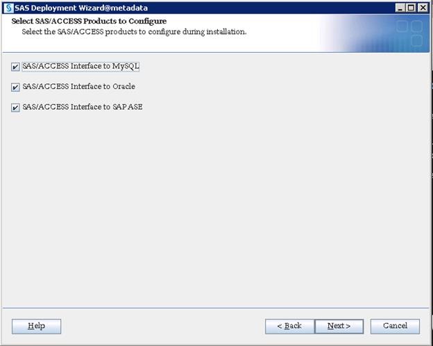
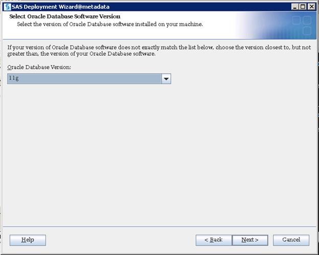

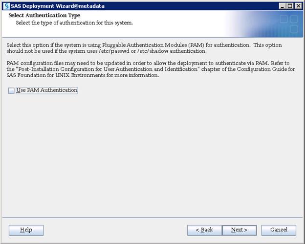
Sas-environment.xml file is created where your Web Server is deployed. Any processes will not access this URL during the installation, but this is helpful while running any web processes from the SAS clients after installation. Providing a sas-environment.xml URL helps for various SAS clients, such as SAS EM, SAS FS etc., to access SAS environment which is mandatory. However, this is not required for deploying SAS Visual Analytics, but as a best practice it is beneficial to provide the URL in the configuration, anticipating additional products in the future.
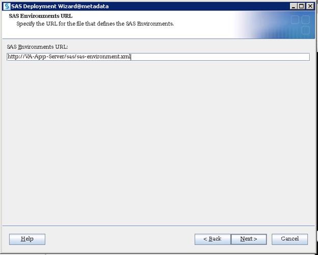
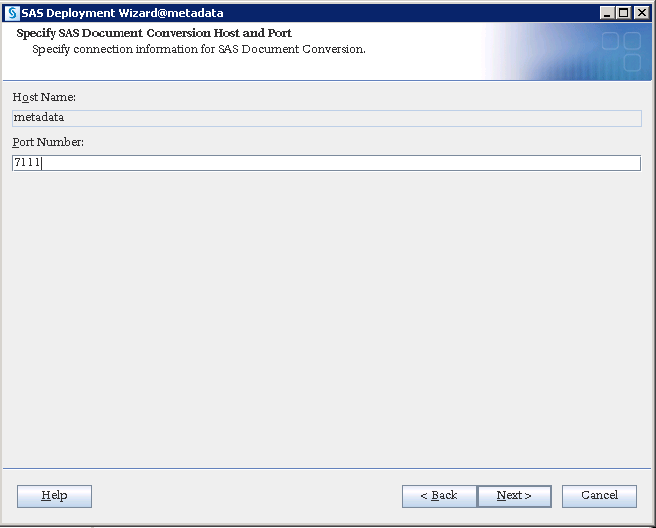
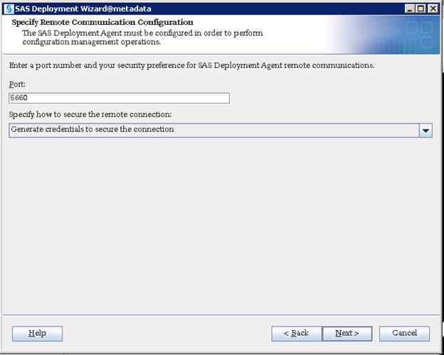
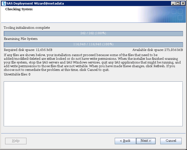
12. Click Start to being the installation.
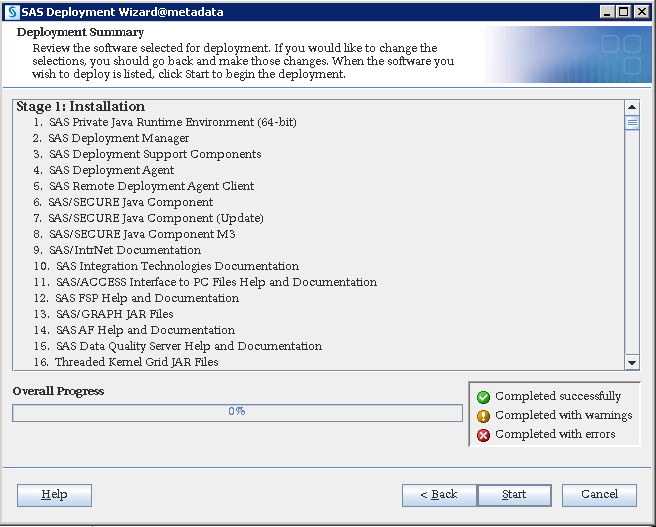
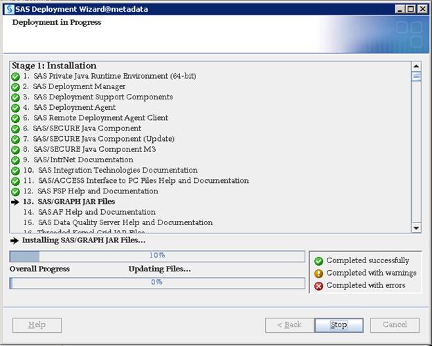
13. Click Next and the click Finish when the installation completes.
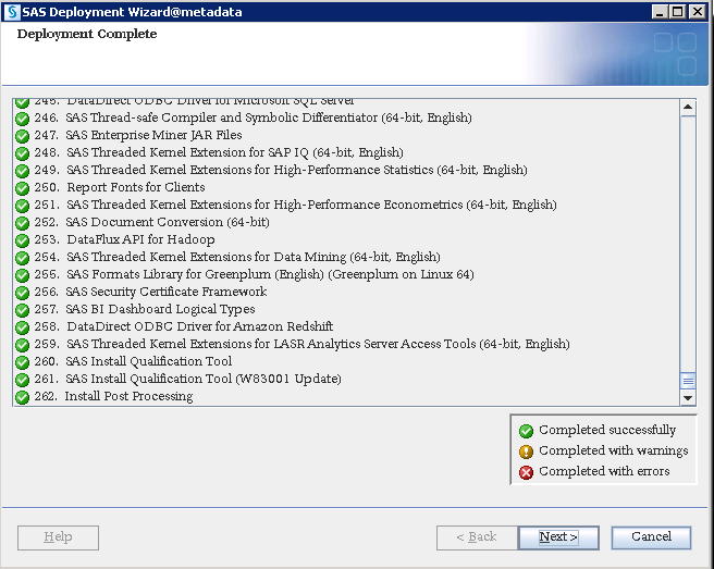

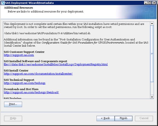
Configuration
Configuration deploys files with various scripts and parameter files that help in starting, stopping, and maintaining the required services and ports.
1. Login as root and run the setuid.sh script before starting configuration.
$ /data/disk1/sas/sashome/SASFoundation/9.4/utilities/bin/setuid.sh

As SAS uses host authentication, it requires various OS users to access configuration files. Being one of the OS users, SAS Installer ID cannot have ability to switch authentication between other OS IDs and this is possible with only Root ID. To keep the installation and configuration owned by SAS we run setuid.sh script with Root, which will set root ownership on required files used for managing authentication. There are three files that will be changed to root ownership (elssrv, sasauth and sasperm) by running the script.

2. Login as sas user and run the command to start the configuration.
$ cd SASDepot_94_dist
$ ./setup.sh &
![]()
3. Select “Install SAS software”. Click Next.

4. Select the SAS Home location where you installed metadata binaries and click Next.
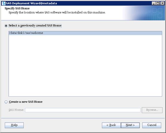
5. Select “Perform a Planned Deployment” and only select “Configure SAS Software”.
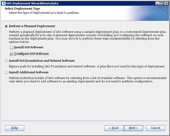
6. Navigate to plan.xml file and click Next.
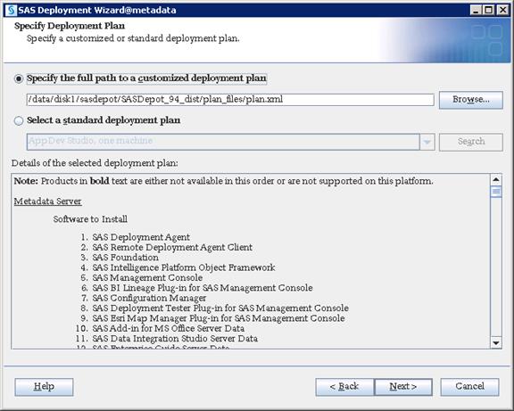
7. Select “Metadata Server” from the drop-down list.
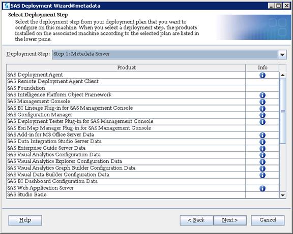
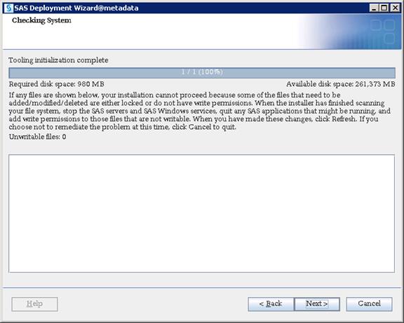
8. Select “Custom” which takes you through all of the configuration screens. Click Next.
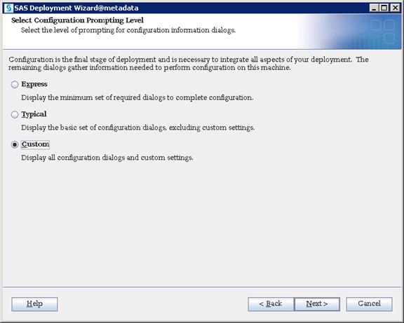
9. Navigate to SAS Configuration location where you want to deploy SAS configuration data.
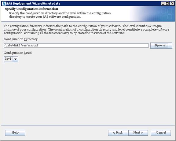
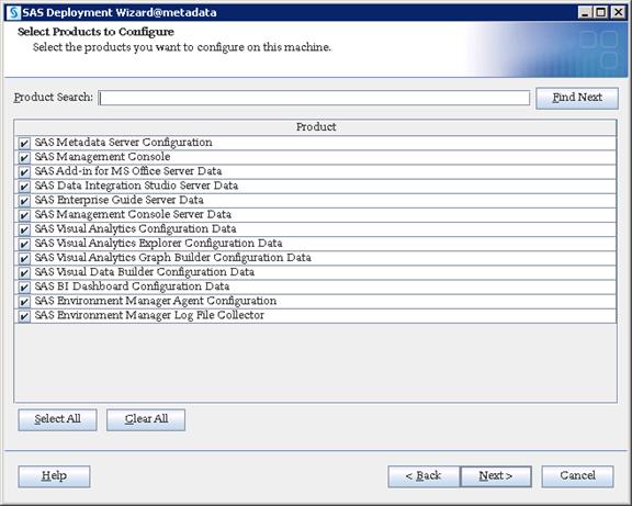
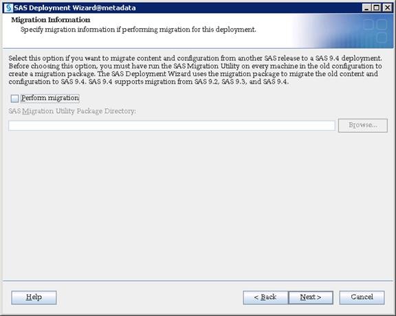
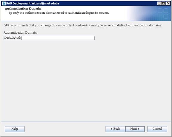
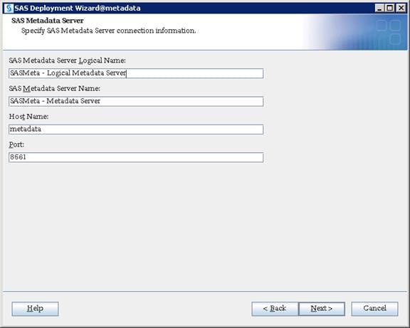

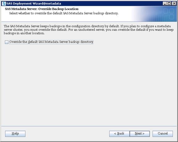
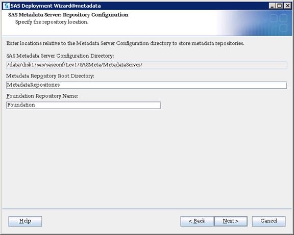
10. Select “Use SAS internal accounts when appropriate”.
This allows SAS to create its internal accounts like sasadm@saspw for the Admin account.
![]() You have to set the external IDs(OS IDs) and continue to provide the credentials in further steps if you do not choose this option.
You have to set the external IDs(OS IDs) and continue to provide the credentials in further steps if you do not choose this option.
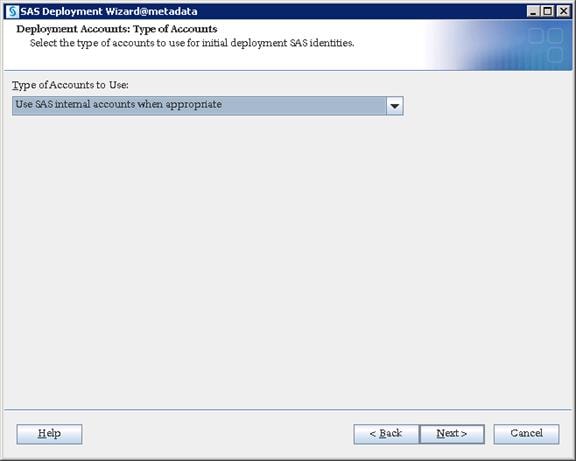
11. Give “sas” user and password as SAS installer. Click Next.
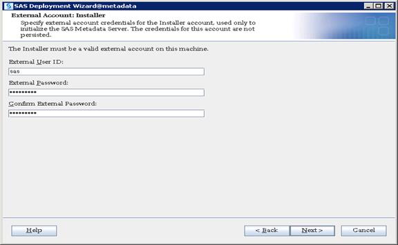
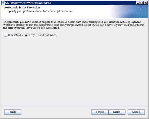
12. Provide a password for the sasadm@saspw account and enable the checkbox to set same password for other internal accounts.
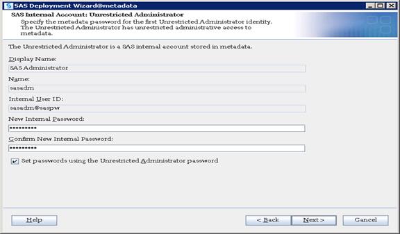
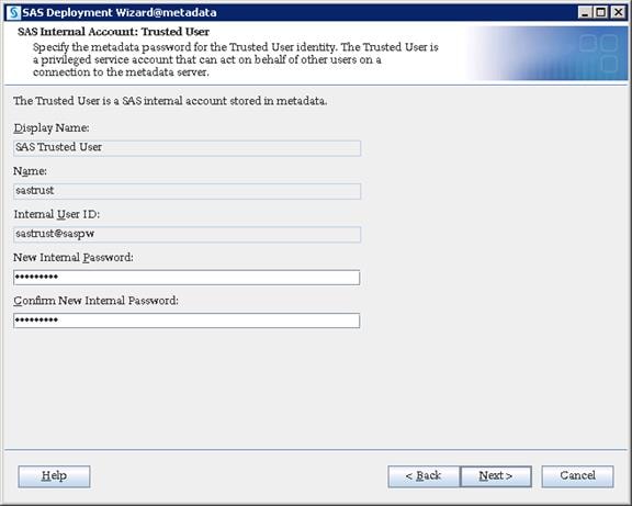
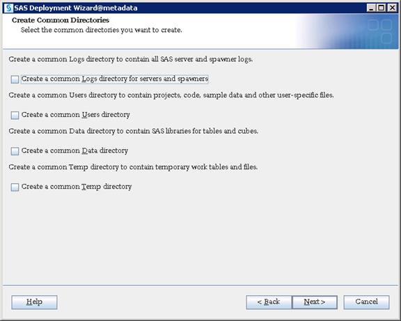
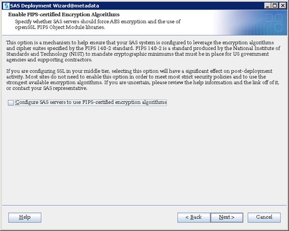
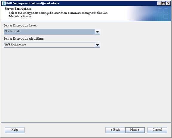
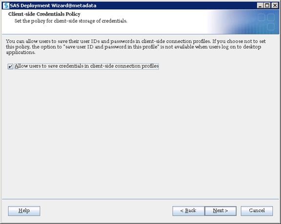

13. Provide the hostname of your SMTP e-mail server and port number. Click Next.
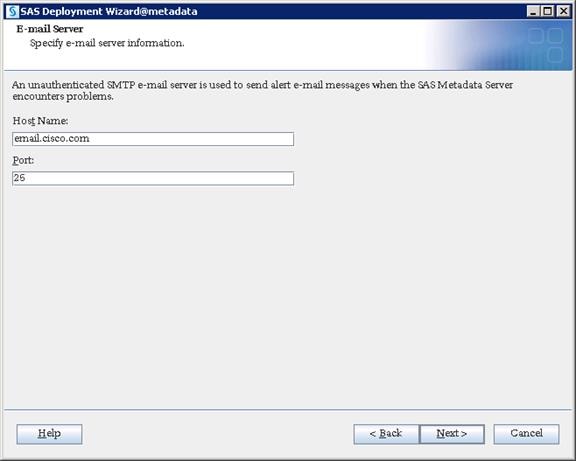
14. Provide a recipient email address which could be either an individual email ID or a Distribution list. Click Next.
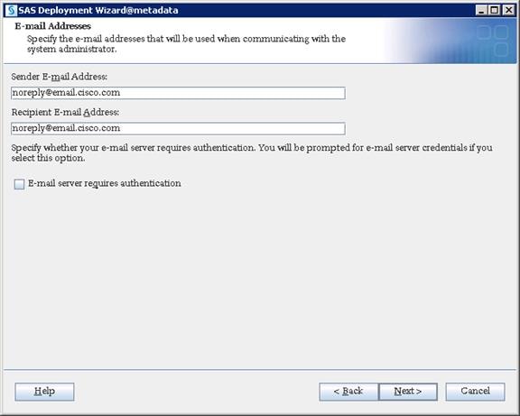
15. Provide your Middle Tier server hostname. Click Next.
![]() Note: Every SAS Tier contains a SAS Environment Manager Agent which communicates with the SAS Environment Manager Host that will be installed in SAS Middle Tier. Therefore, you pointed ports to the Middle Tier previously. There will be no communication during installation, but the SAS Environment Manager requires this communication after the installation.
Note: Every SAS Tier contains a SAS Environment Manager Agent which communicates with the SAS Environment Manager Host that will be installed in SAS Middle Tier. Therefore, you pointed ports to the Middle Tier previously. There will be no communication during installation, but the SAS Environment Manager requires this communication after the installation.
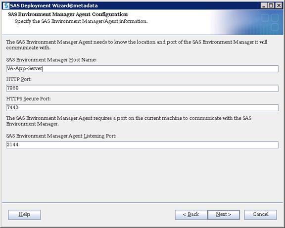
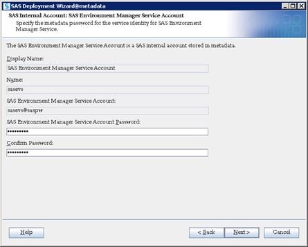
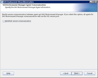
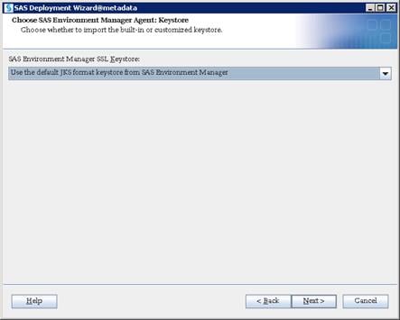
16. Click Start to begin the configuration.
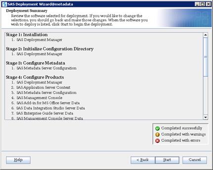
17. Click Next and then click Finish when configuration completes.
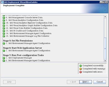
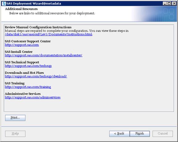
SAS Compute Tier Installation
SAS Compute Tier contains services that performs analytical and reporting processes for various SAS clients.
Installation
To deploy all the binaries of the selected SAS tier, complete the following steps:
1. Login to va-compute server as sas user and run the command to start the installation.
$ cd SASDepot_94_dist
$ ./setup.sh &
![]()
2. Select “Install SAS software”. Click Next.
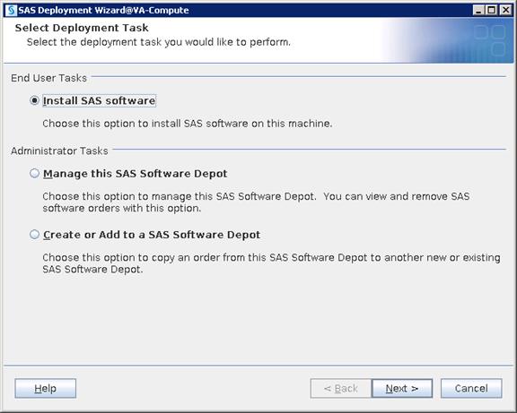
3. Navigate to SAS Home directory where you want to deploy SAS Compute binaries.
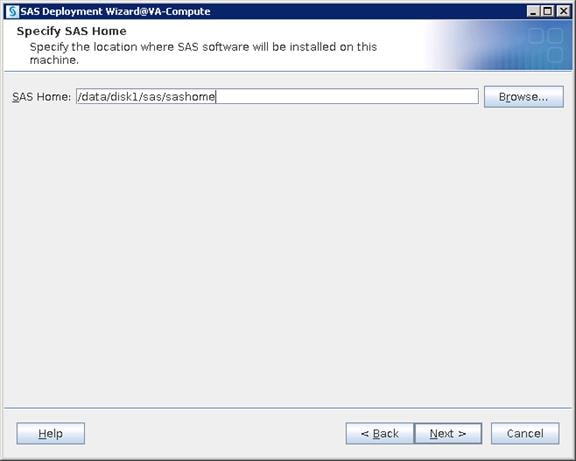
4. Select “Perform a Planned Deployment” and “Install SAS Software”.
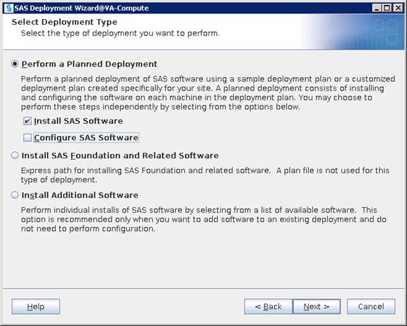
5. Place plan.xml file in some accessible location on server and navigate to the file. Click Next.
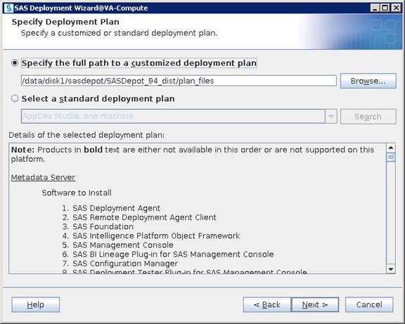
6. Select “SAS Application Server” from the drop-down list.
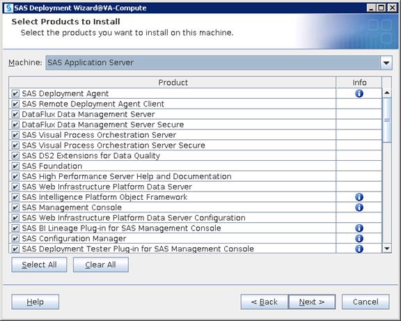
7. Navigate to the license SID file located in the “sid_files” folder in your depot.
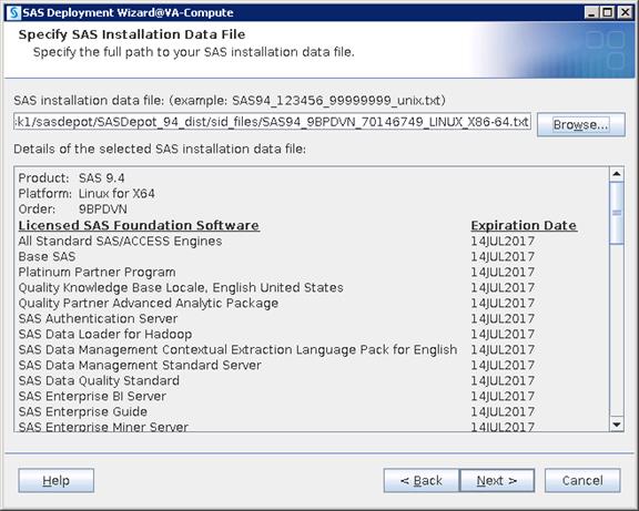
8. Select the languages you would like to install for the products listed below.
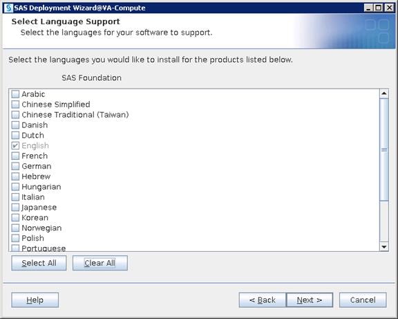
9. Select the language locale from the drop-down list and click Next.
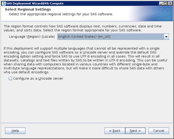

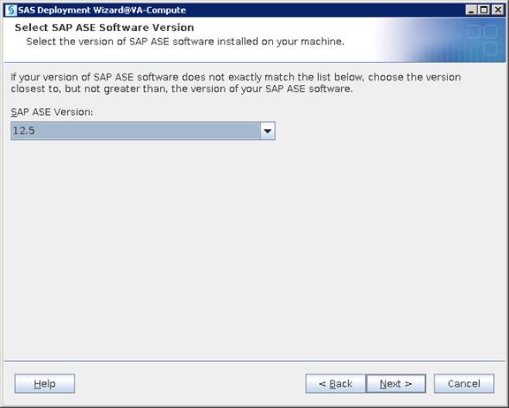
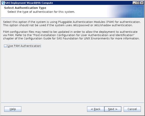
10. Provide the URL to access sas-environment.xml

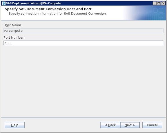
11. Navigate to the license SID file located in the “sid_files” folder in your depot.
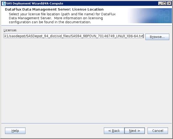
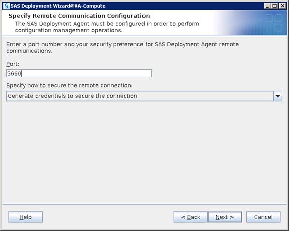
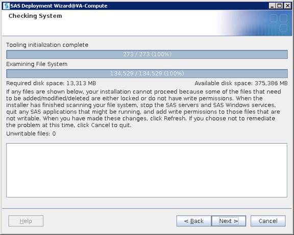

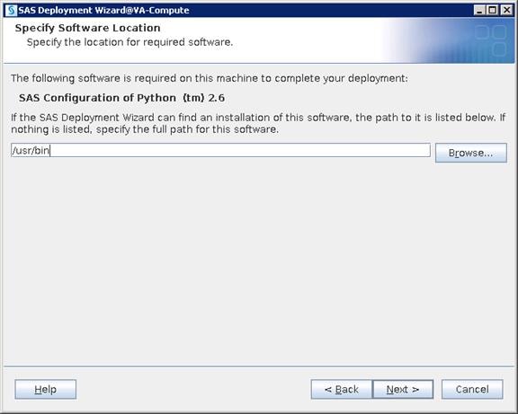
12. Click Start to begin the installation.
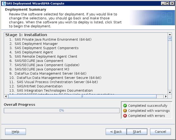
13. Click Next and then click Finish when the installation completes.
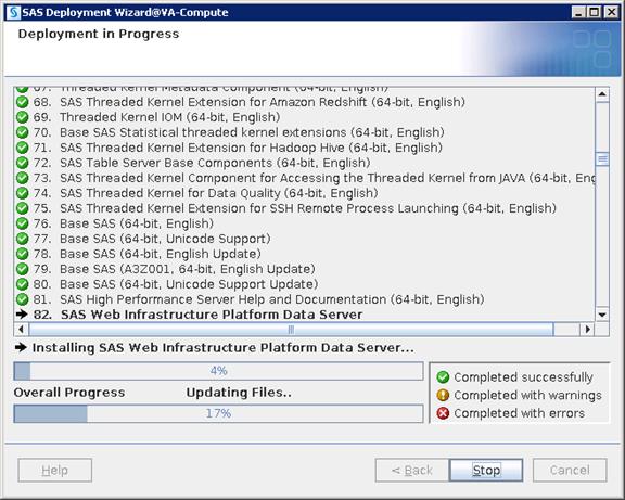
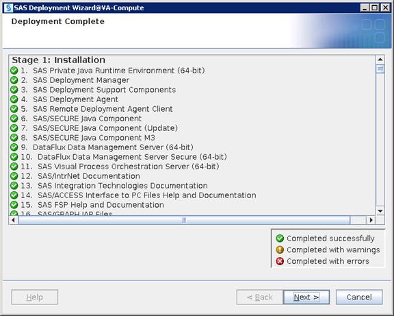
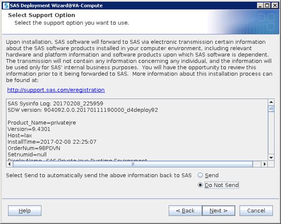
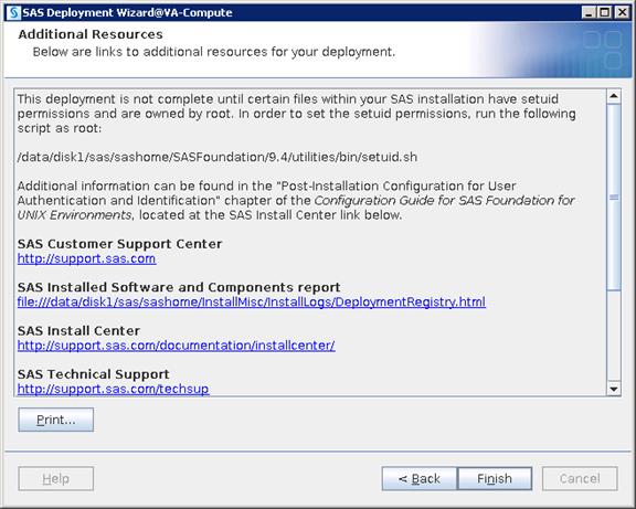
Configuration
Configuration deploys files with various scripts and parameter files which help in starting, stopping and maintaining required services and ports.
1. Login as root and run the setuid.sh script before starting configuration.
# /data/disk1/sas/sashome/SASFoundation/9.4/utilities/bin/setuid.sh

![]() Note: As SAS uses host authentication, it requires various OS users to access configuration files. Being one of OS users, SAS Installer ID cannot have ability to switch authentication between other OS IDs and this is possible with only Root ID. To keep the installation and configuration owned by SAS we run setuid.sh script with Root, which will set root ownership on required files used for managing authentication. There are three files that will be changed to root ownership (elssrv, sasauth and sasperm) by running the script.
Note: As SAS uses host authentication, it requires various OS users to access configuration files. Being one of OS users, SAS Installer ID cannot have ability to switch authentication between other OS IDs and this is possible with only Root ID. To keep the installation and configuration owned by SAS we run setuid.sh script with Root, which will set root ownership on required files used for managing authentication. There are three files that will be changed to root ownership (elssrv, sasauth and sasperm) by running the script.
2. Login as a sas user and run command to start configuration.
$ cd SASDepot_94_dist
$ ./setup.sh &
![]()
3. Select “Install SAS software”. Click Next.

4. Select “Perform a Planned Deployment” and select only “Configure SAS Software”.

5. Navigate to plan.xml file and click Next.

6. Select “SAS Application Server” from the drop-down list.
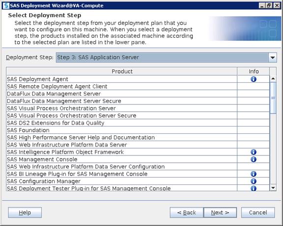
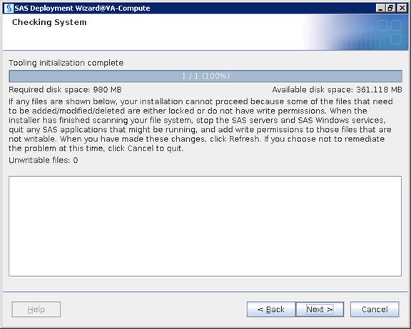
7. Select “Custom” which will take you through all the screens of configuration. Click Next.
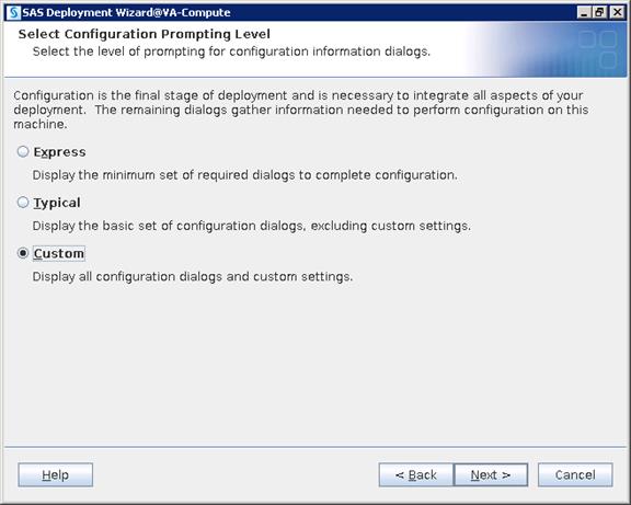
8. Navigate to the SAS Configuration location where you want to deploy SAS configuration data.
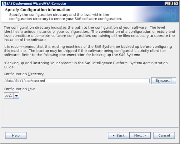

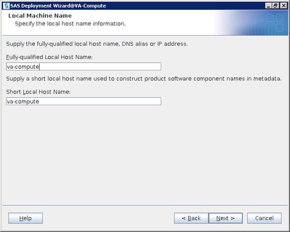
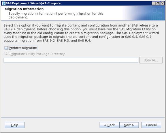
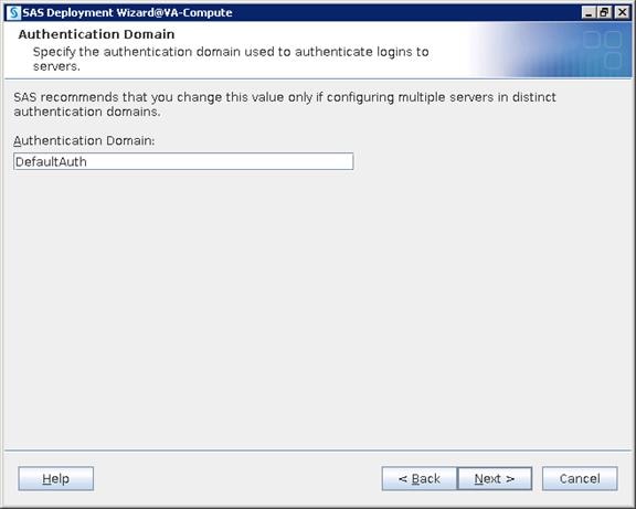
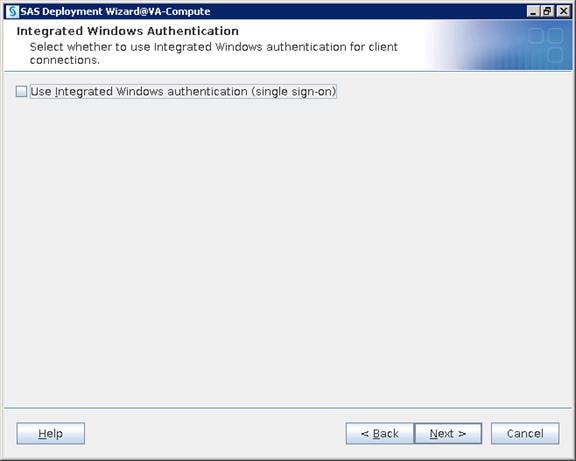
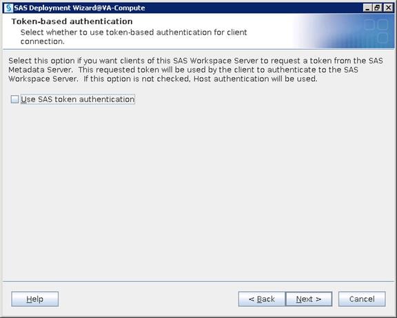
9. Provide the metadata server Hostname and Port number.
![]() Note: In this deployment hostname of metadata server is “metadata” and port in 8561.
Note: In this deployment hostname of metadata server is “metadata” and port in 8561.
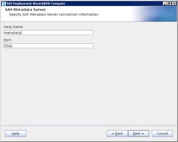
10. Select “Use SAS internal accounts when appropriate”.
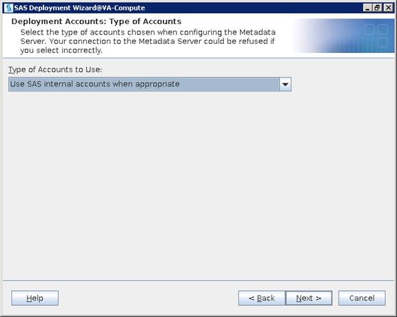
11. Provide a password for the sasadm@saspw account that was given in the metadata configuration and enable the checkbox to set the same password for the other internal accounts.
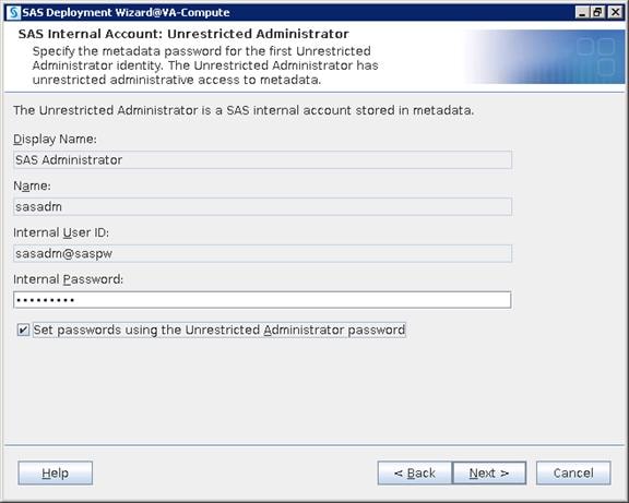
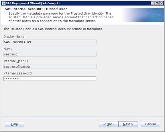
12. Provide the credentials “sassrv” OS user. Click Next.
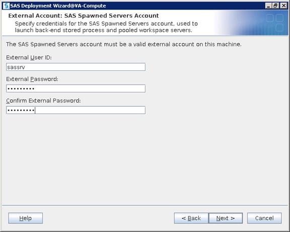
13. Check the box for setting up First User Identity for testing application from any client. You will use the “sasdemo” OS account.
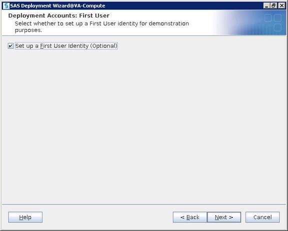
14. Provide the OS user that is created – sasdemo.
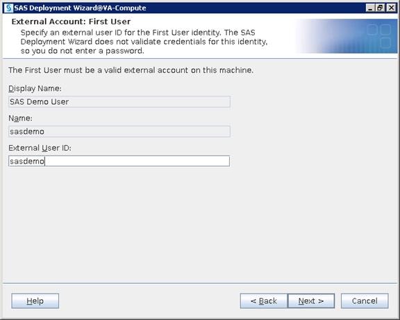
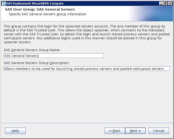

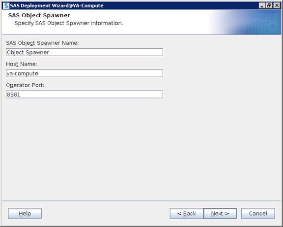
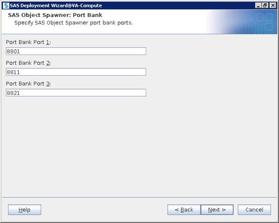
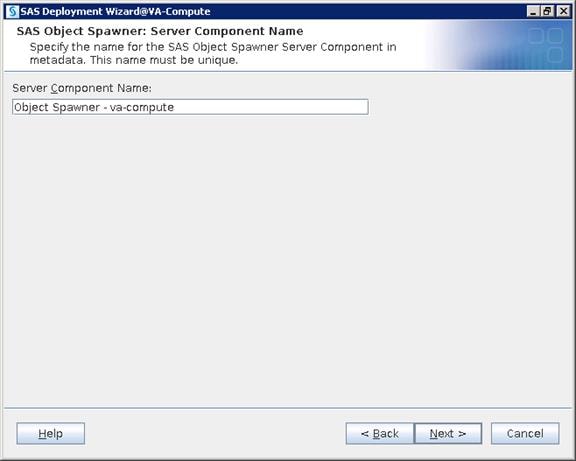
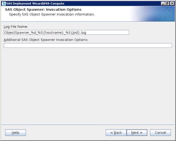
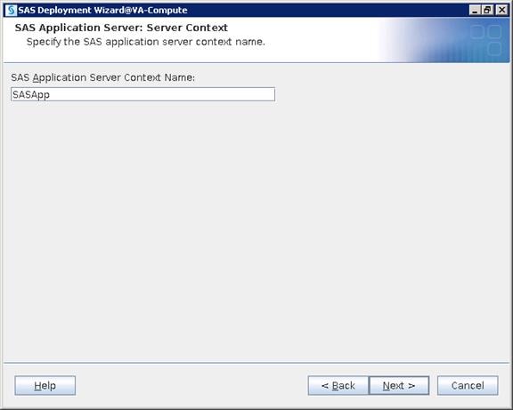
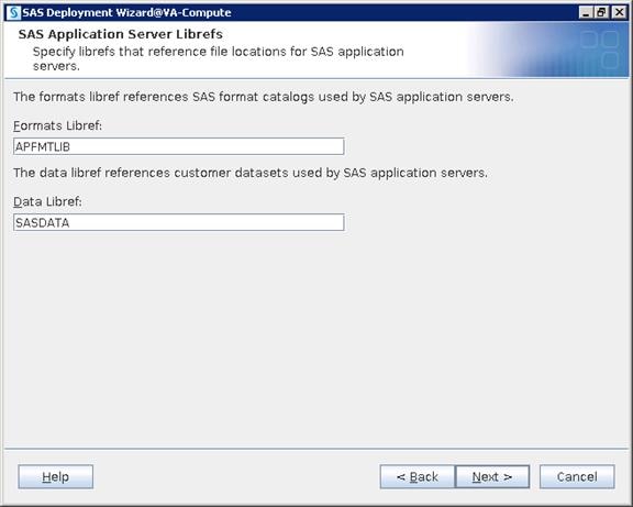
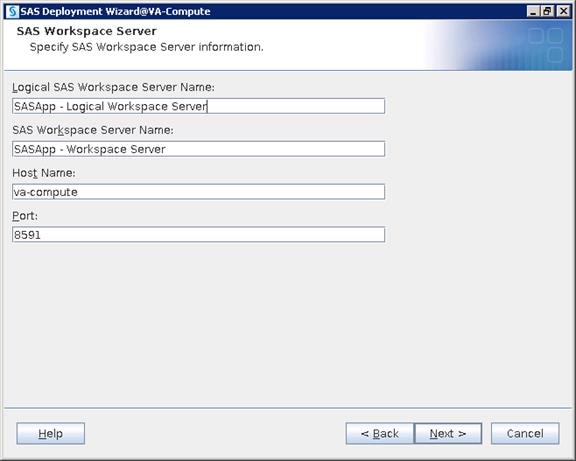
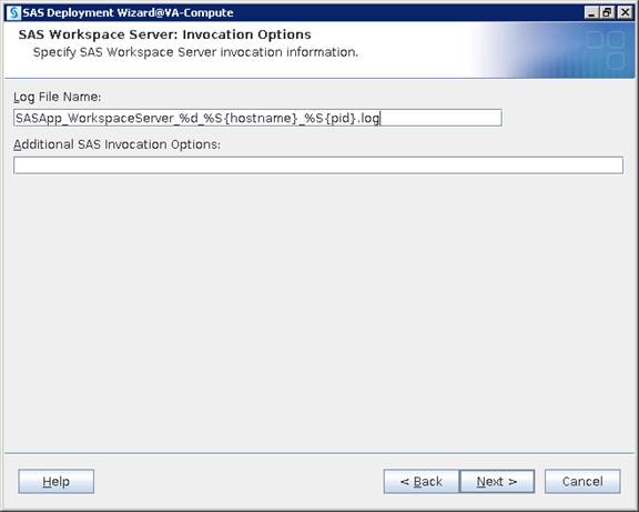
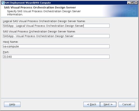
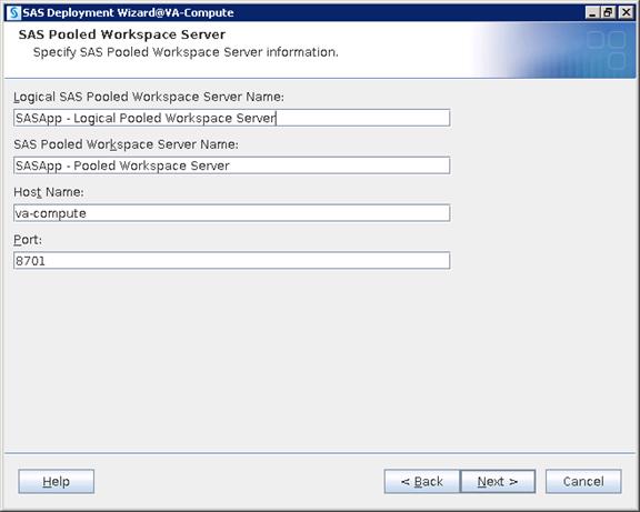
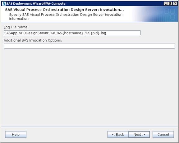
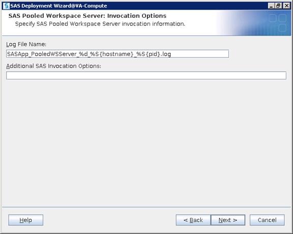
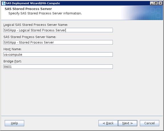


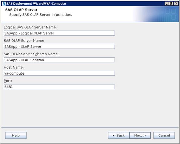
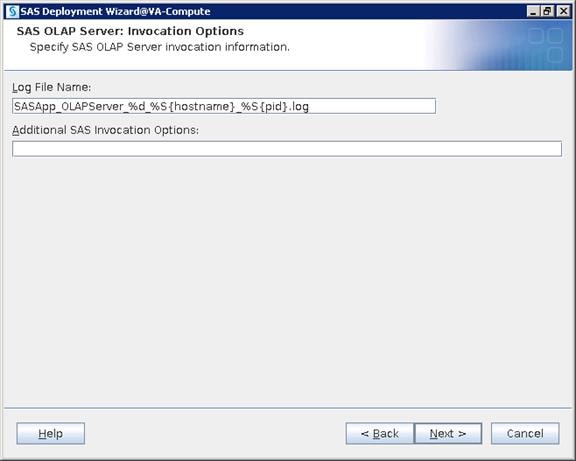
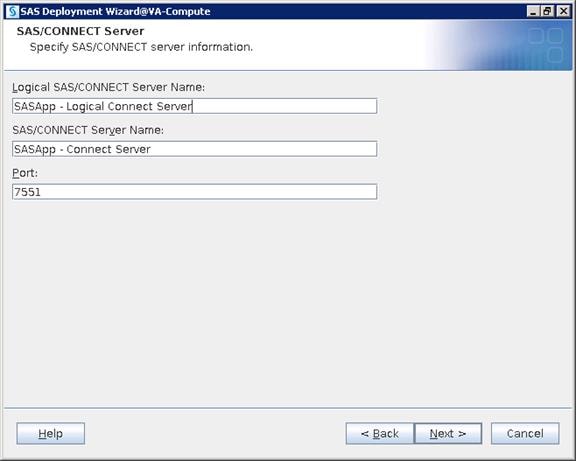
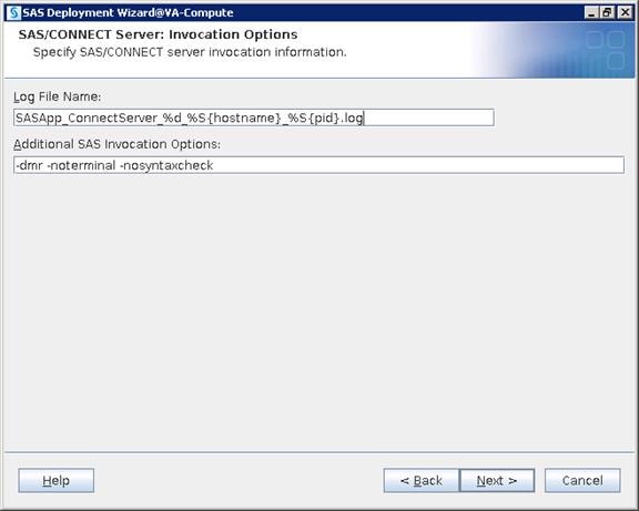
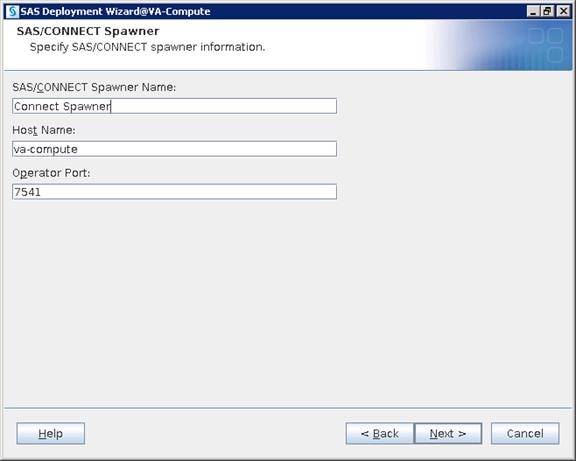

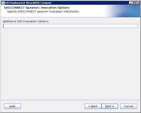
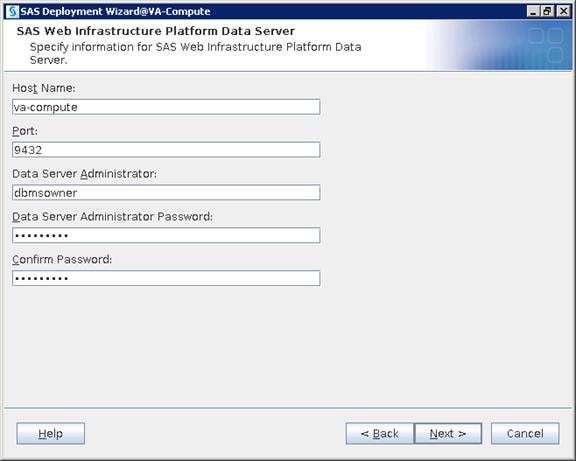
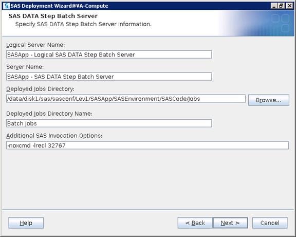
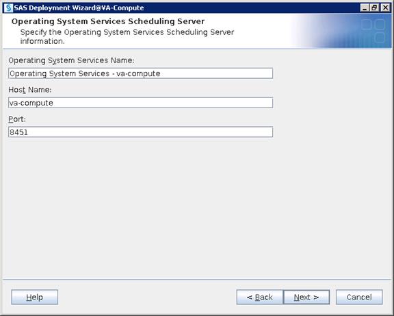
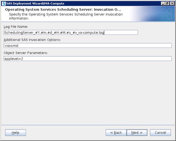
15. Unzip and place the junit-4.10.jar file in any accessible location on the server and browse to the file. Click Next.
![]() Note: You can download the junit jar file using this link http://www.java2s.com/Code/JarDownload/junit/junit-4.10.jar.zip
Note: You can download the junit jar file using this link http://www.java2s.com/Code/JarDownload/junit/junit-4.10.jar.zip
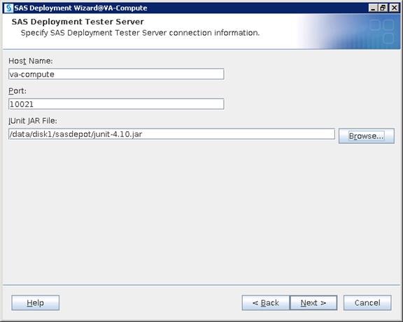
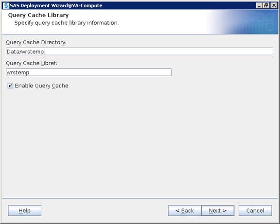
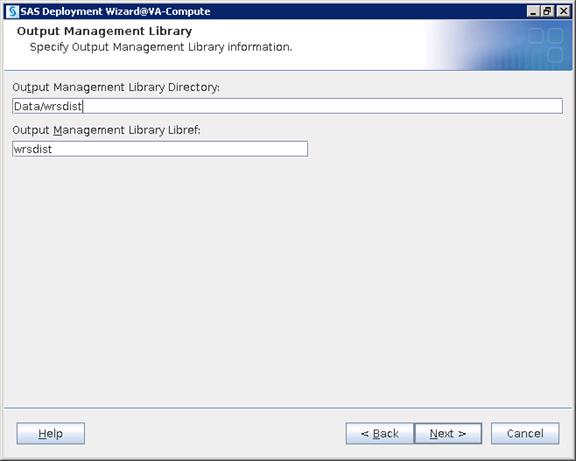
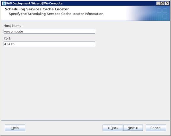


![]() Note: SAS uses multicast security by default. During installation, the SAS Deployment Wizard supplies you with a default multicast address and port number that it generates based on metadata server’s IP address. There is no manual input needed here.
Note: SAS uses multicast security by default. During installation, the SAS Deployment Wizard supplies you with a default multicast address and port number that it generates based on metadata server’s IP address. There is no manual input needed here.
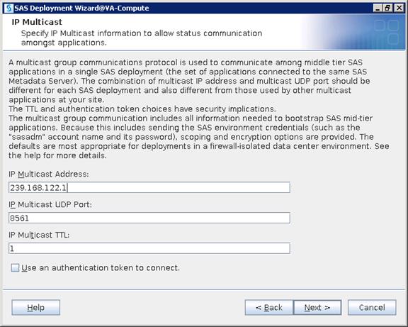
16. Provide your Middle Tier server hostname for the SAS Environment Manager Hostname. Click Next.
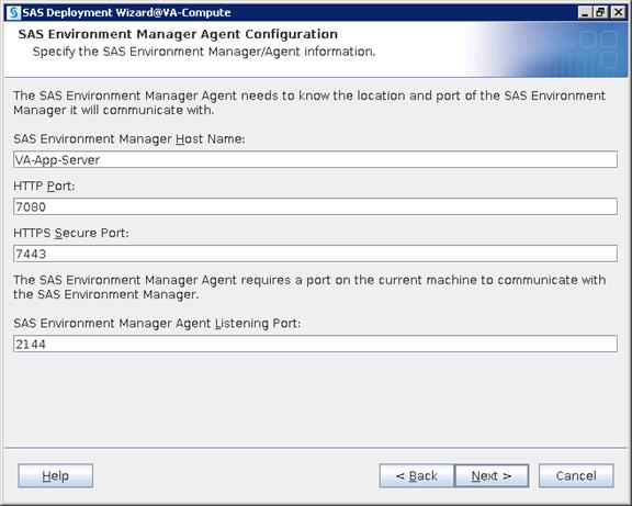
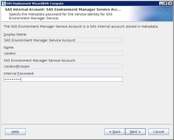

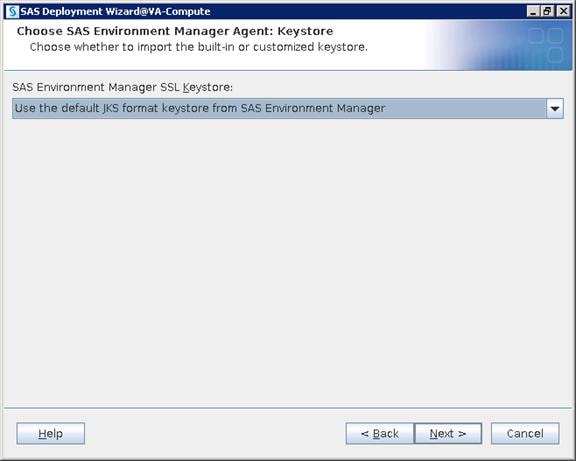
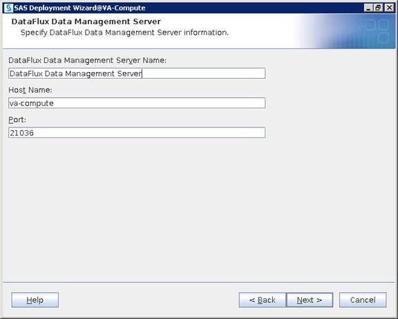
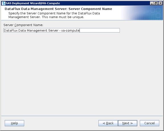
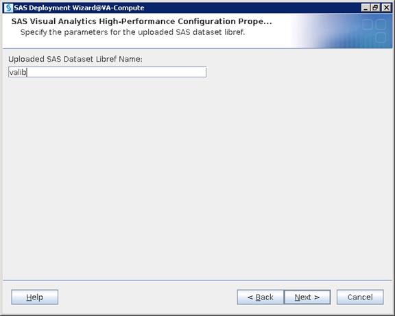
17. Select Hadoop (co-located HDFS). Click Next.
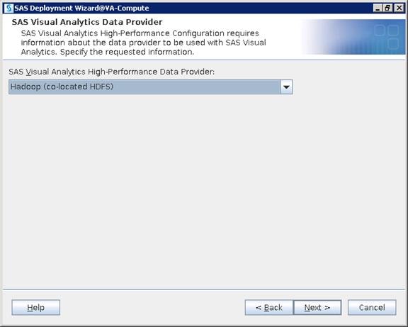
18. Provide SAS HPAE/LASR Root Node Hostname.
a. Create an accessible directory in rhel1 for Signature Files and give the location
b. Provide TKGrid path as /opt/sas/TKGrid
c. Provide SAS HPCMC URL
d. Provide TKTGDat path as /opt/sas/TKTGDat
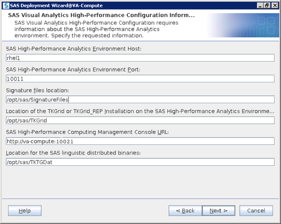
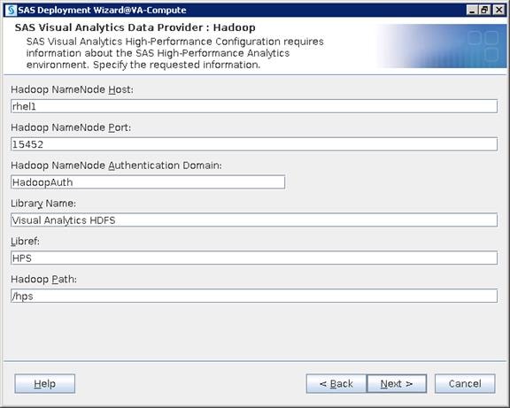

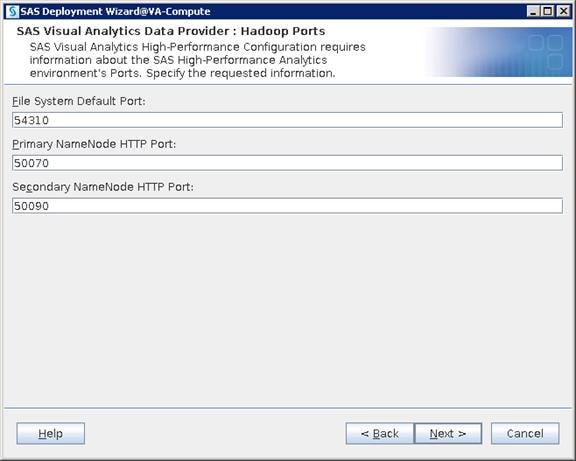
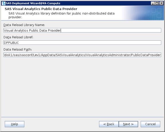
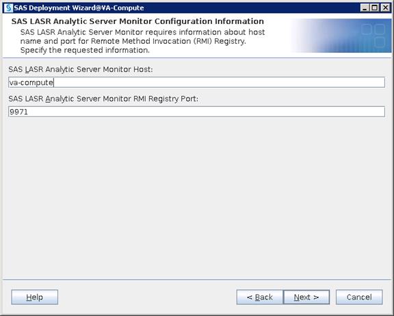

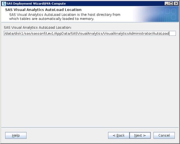
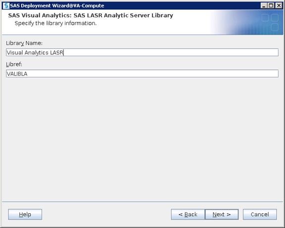


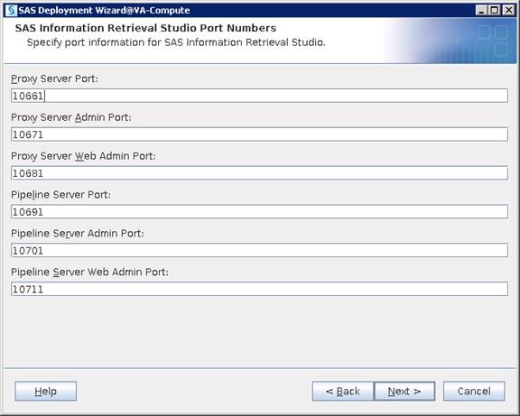

19. Select “Cloudera” for Hadoop Distribution from the drop-down list. Click Next.
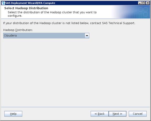
20. Select “Cloudera Manager” for cluster manager. Click Next.
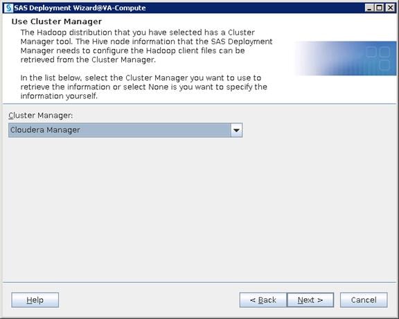

21. Provide the Cloudera Manager’s admin credentials. Click Next.
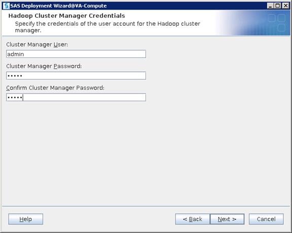
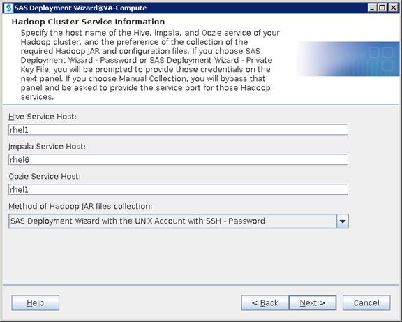
22. Provide the Root credentials. Click Next.
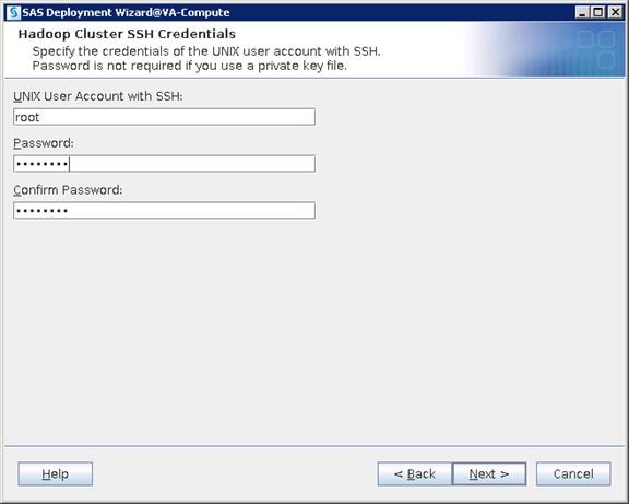
![]() Note: The server rhel1 requires you to install the ‘strace’ package.
Note: The server rhel1 requires you to install the ‘strace’ package.
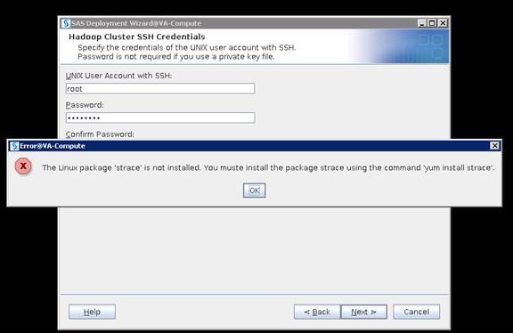
23. Logon to Name Node, install Strace package on Name Node and click OK and click Next in the above window.
24. Command to install package: yum install strace
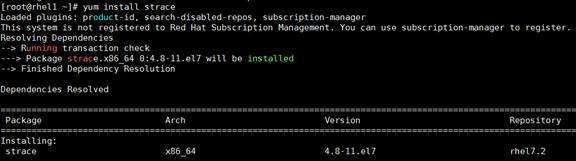
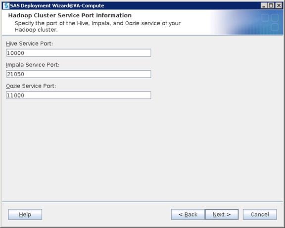
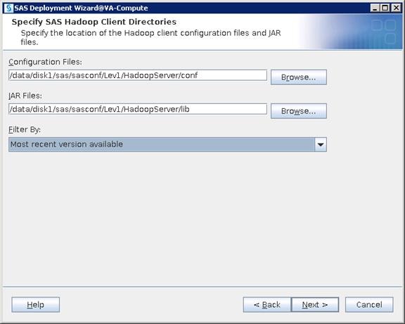
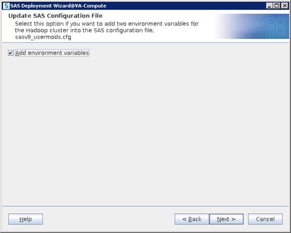
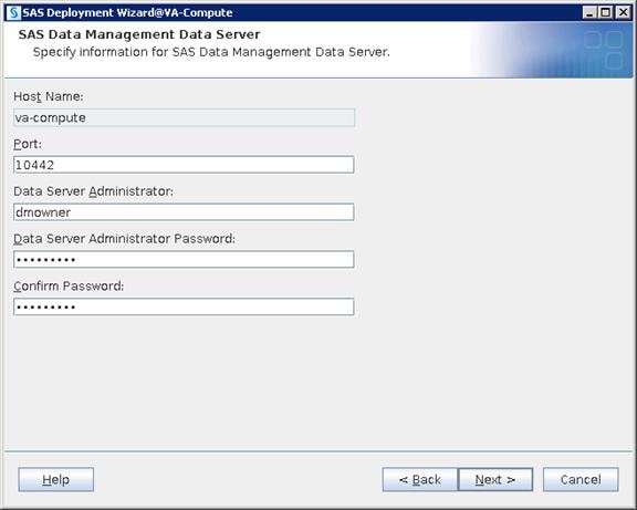
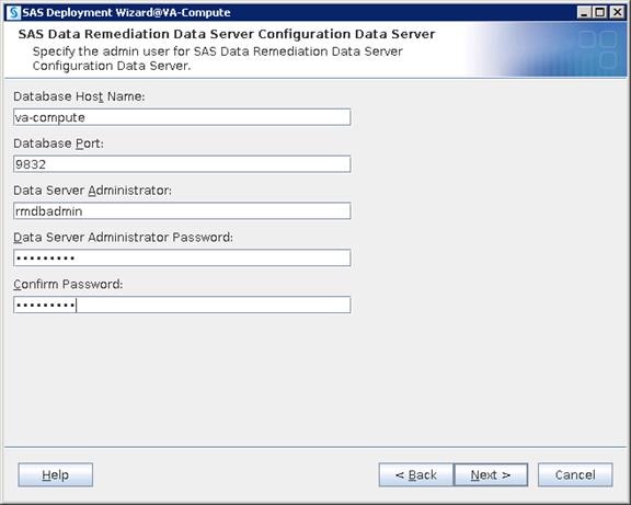
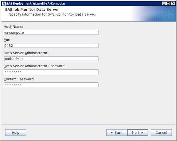
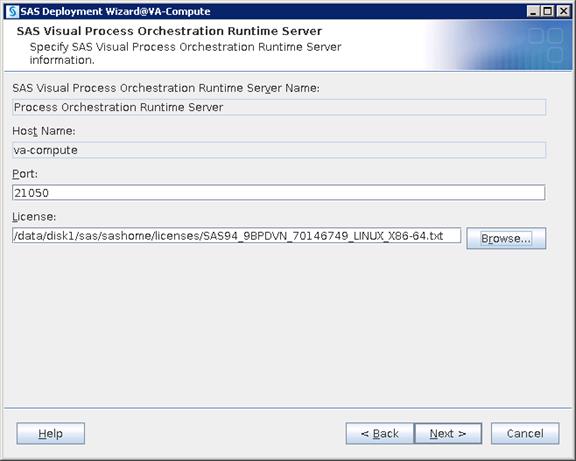
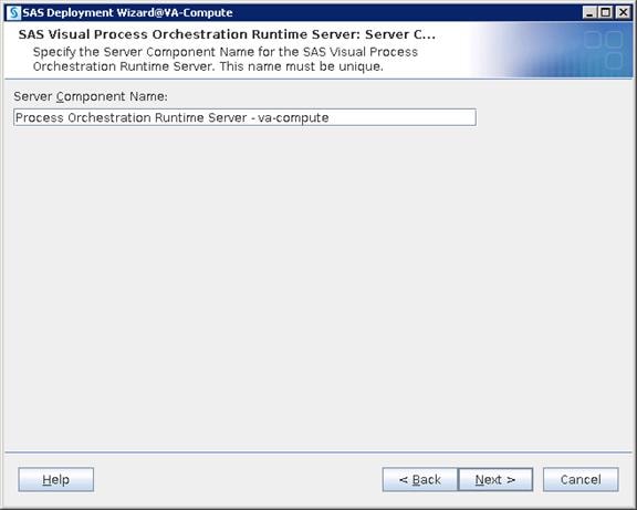
25. Click Start to begin the configuration.
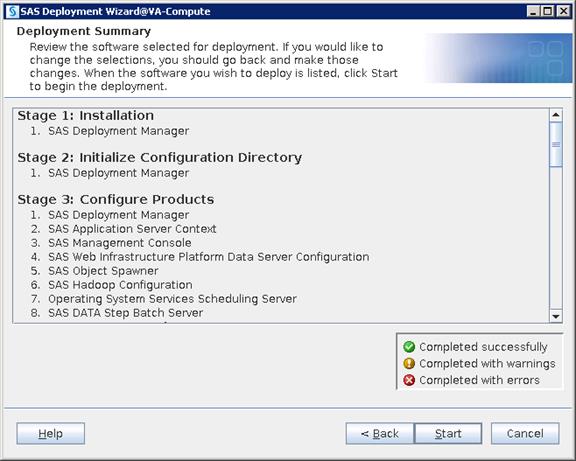
26. Click Next and then click Finish when configuration completes.
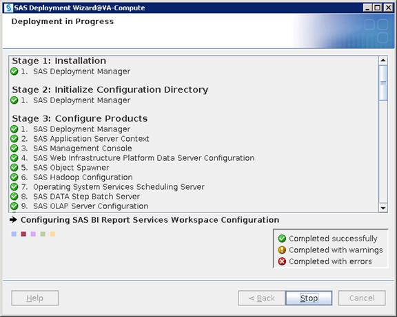
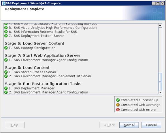
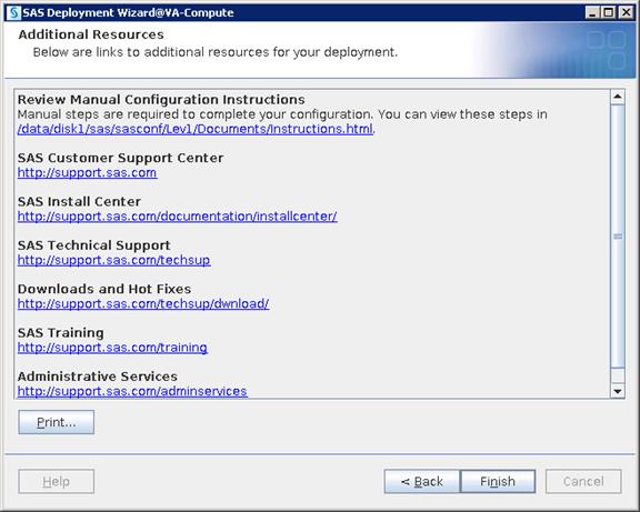
SAS Middle Tier Installation
SAS Middle Tier enables users to access data and functionality via a Web browser. This tier provides Web-based interfaces for report creation and information distribution, while passing analysis and processing requests to the SAS servers.
Installation
To deploy all the binaries of the particular SAS tier that is selected, complete the following steps:
1. Login to va-app-server as sas user and run the following command to start the installation.
$ cd SASDepot_94_dist
$ ./setup.sh &
![]()
2. Select “Install SAS software”. Click Next.
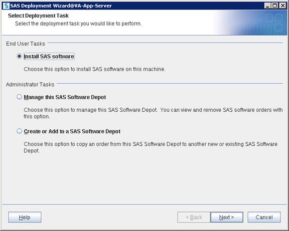
3. Navigate to SAS Home directory where you want to deploy SAS Middle Tier binaries.
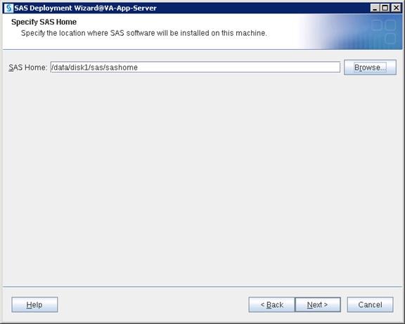
4. Select “Perform a Planned Deployment” and “Install SAS Software”. Click Next.

5. Place plan.xml file in an accessible location on server and navigate to the file. Click Next.

6. Select “Middle Tier” from the drop-down list.
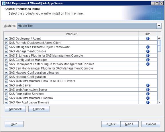
7. Navigate to the license SID file which will be in “sid_files” folder in your depot. Click Next.
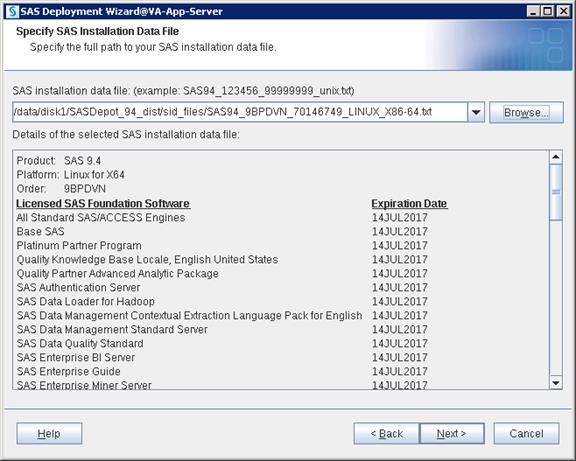
8. Select the languages you would like to install for the products listed below. Click Next.
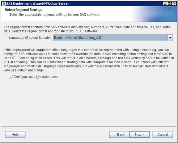
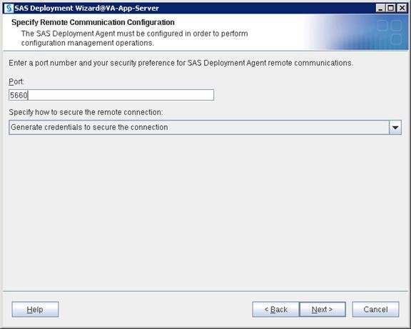
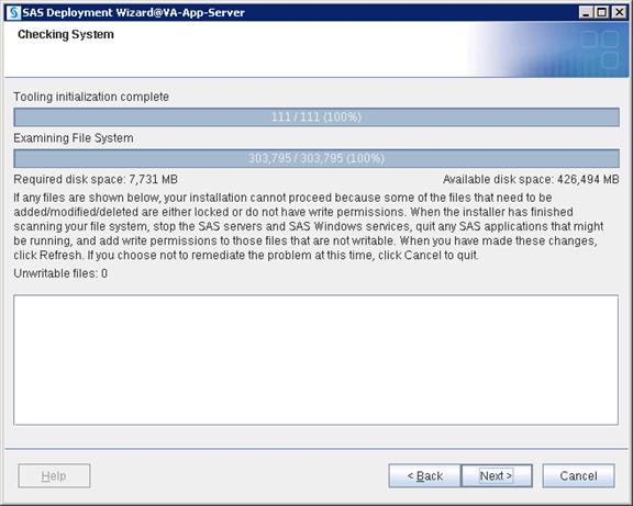
9. Click Start to begin the installation.
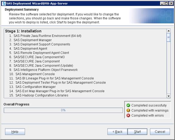
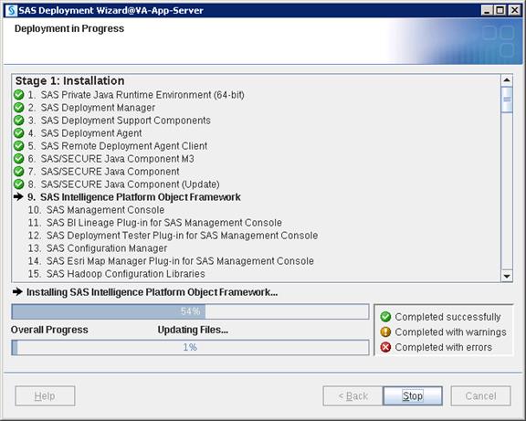
10. Click Next and then click Finish when the installation completes.
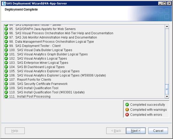
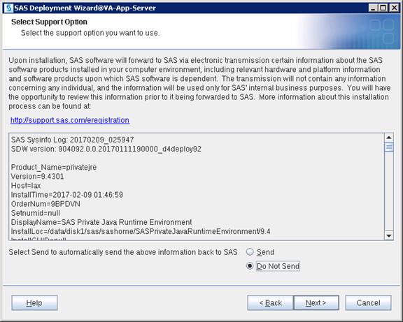
Configuration
Configuration deploys files with various scripts and parameter files which help in starting, stopping and maintaining required services and ports.
1. Login as a sas user and run command to start configuration.
$ cd SASDepot_94_dist
$ ./setup.sh &
![]()
2. Select “Install SAS software”. Click Next.

3. Select the SAS Home location where you installed metadata binaries and click Next.
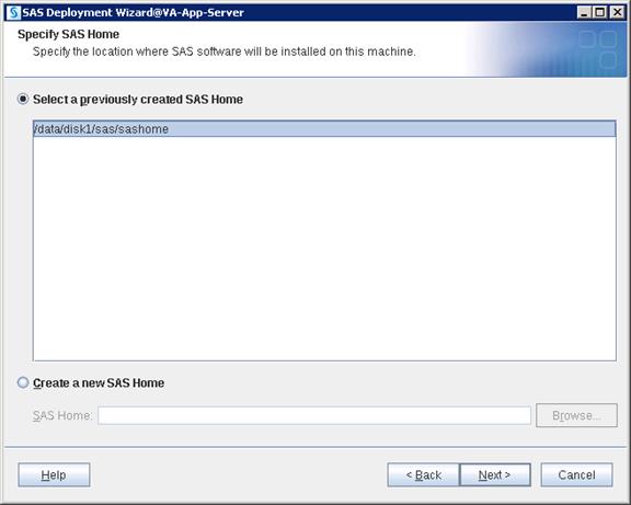
4. Select “Perform a Planned Deployment” and only select “Configure SAS Software”. Click Next.

5. Navigate to the plan.xml file and click Next.

6. Select “Middle Tier” from the drop-down list. Click Next.

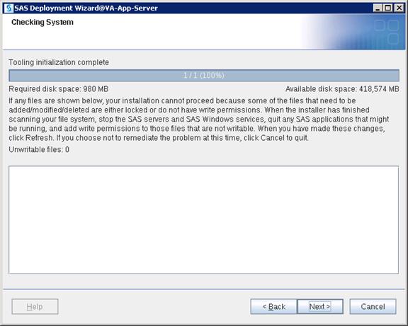
7. Select “Custom” which will take you through all the screens of configuration. Click Next.
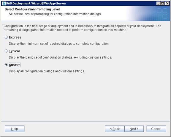
8. Navigate to the SAS Configuration location where you want to deploy SAS configuration data. Click Next
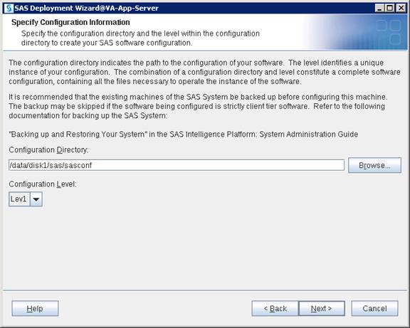
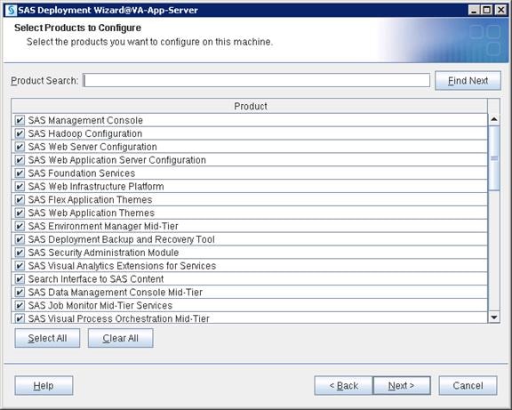
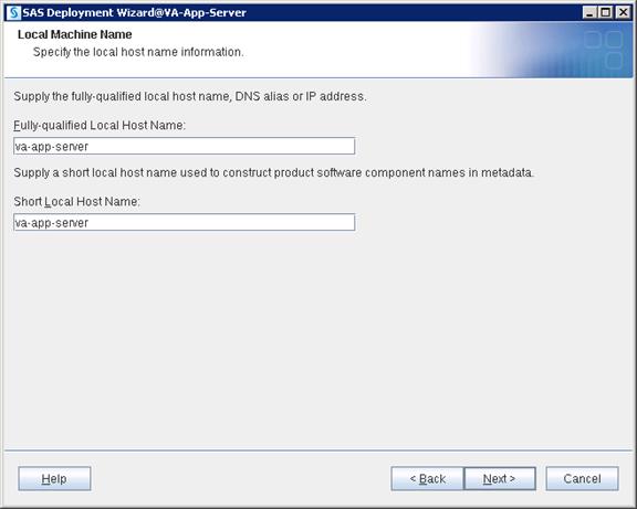
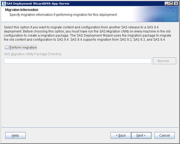

9. Provide the Metadata server hostname and port. Click Next.
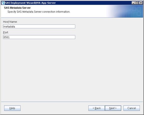
10. Select “Use SAS internal accounts when appropriate”. Click Next.
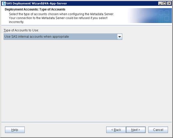
11. Provide the password for the sasadm@saspw account that was given in metadata configuration and enable the checkbox to set same password for the other internal accounts.
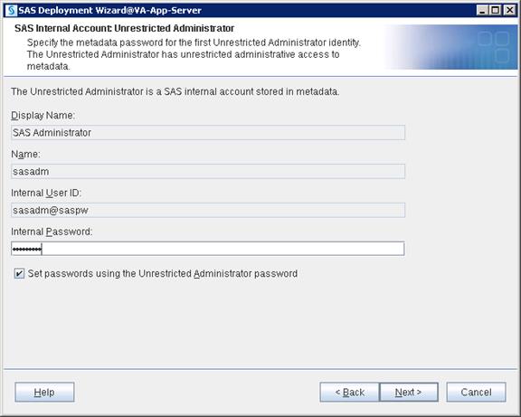
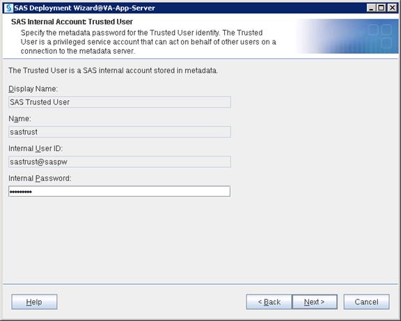

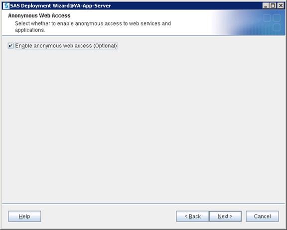
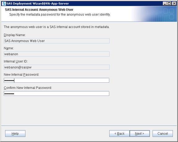
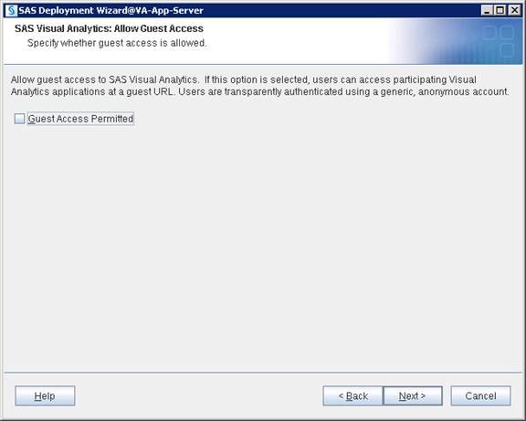
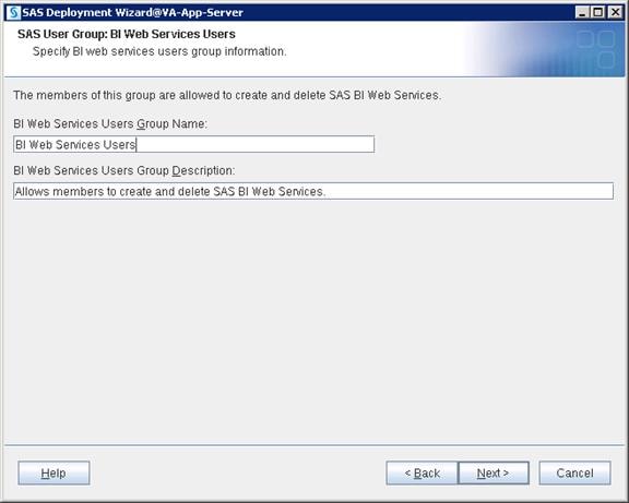


12. Provide your SMTP e-mail server hostname and port number. Click Next.

13. Provide a recipient email address that could be either an individual email ID or a Distribution list. Click Next.
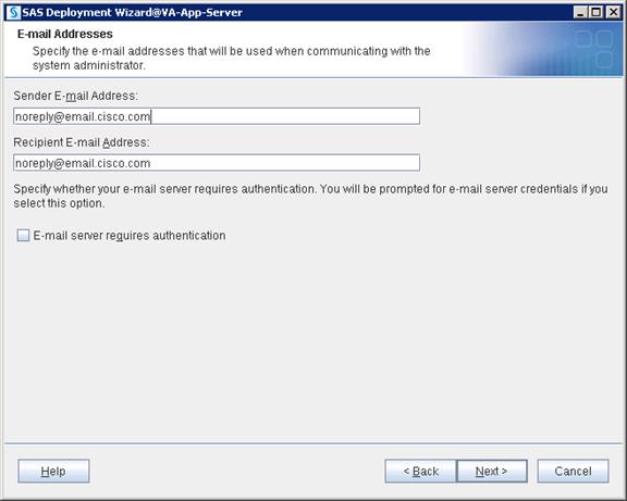
14. Unzip and place the junit-4.10.jar file in an accessible location on the server and browse to the file. Click Next.
![]() Note: You can download junit jar file using this link http://www.java2s.com/Code/JarDownload/junit/junit-4.10.jar.zip
Note: You can download junit jar file using this link http://www.java2s.com/Code/JarDownload/junit/junit-4.10.jar.zip
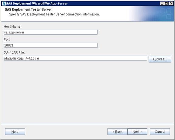
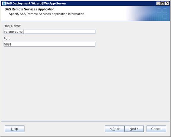
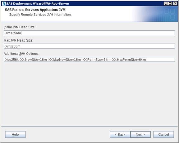
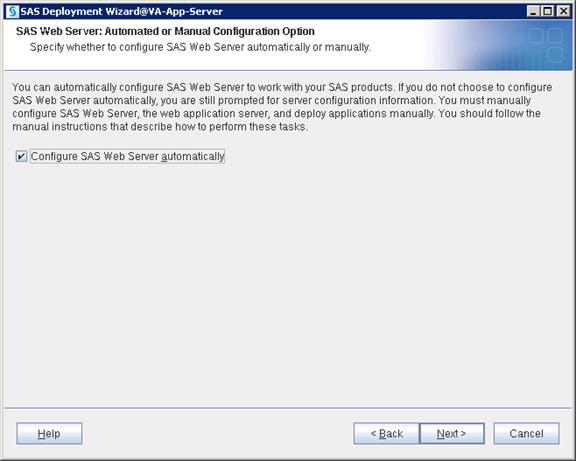
![]() Note: The default http port for the Linux server is 7980. Since 80 was selected and is below 1024, you need to start the Web Server with Root ID when required. Instead of using the Root ID, you may use 7980 as the http port.
Note: The default http port for the Linux server is 7980. Since 80 was selected and is below 1024, you need to start the Web Server with Root ID when required. Instead of using the Root ID, you may use 7980 as the http port.
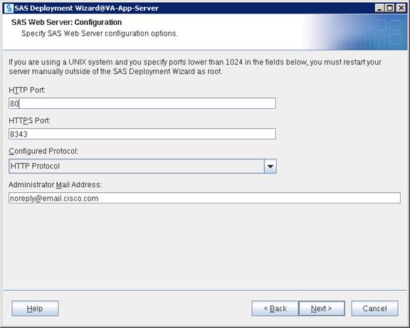
15. Assign the user “sas” and group “sasgrp”. Click Next.
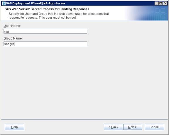
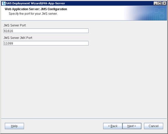


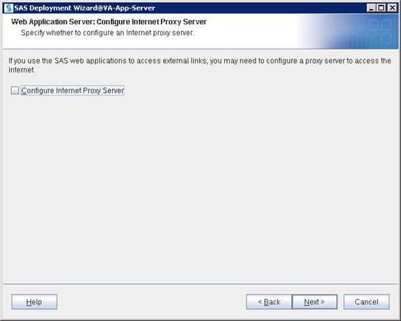
![]() Note: Configuring multiple Web Application Servers creates a dedicated Web App server for each SAS web product in the deployment. This helps with the configuration changes required for specific Web App servers without disturbing others.
Note: Configuring multiple Web Application Servers creates a dedicated Web App server for each SAS web product in the deployment. This helps with the configuration changes required for specific Web App servers without disturbing others.

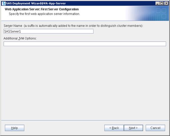
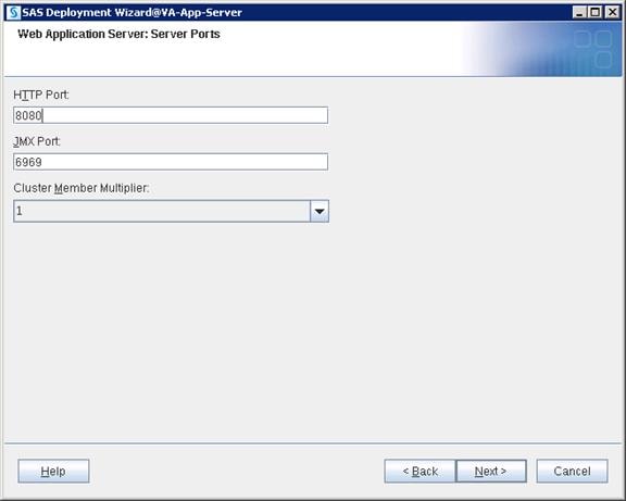


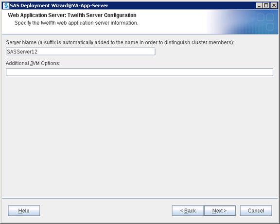

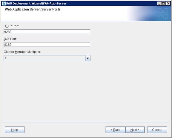


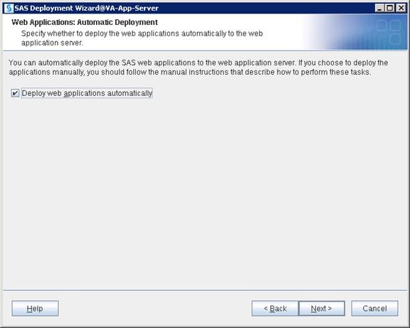
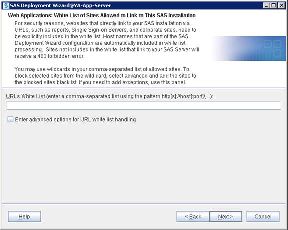
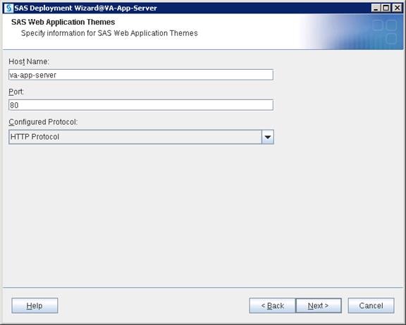
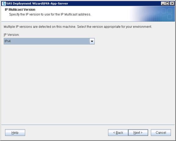

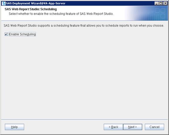
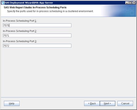


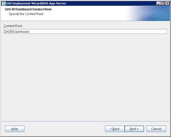
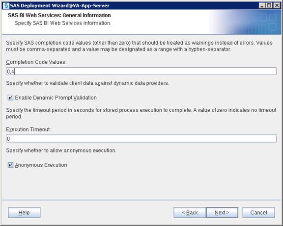
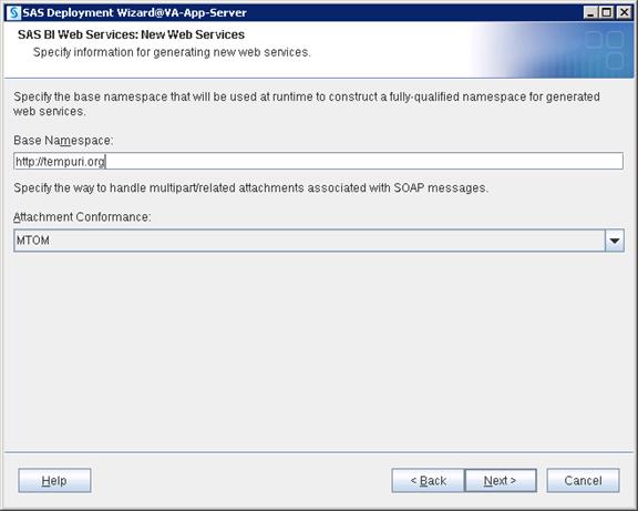

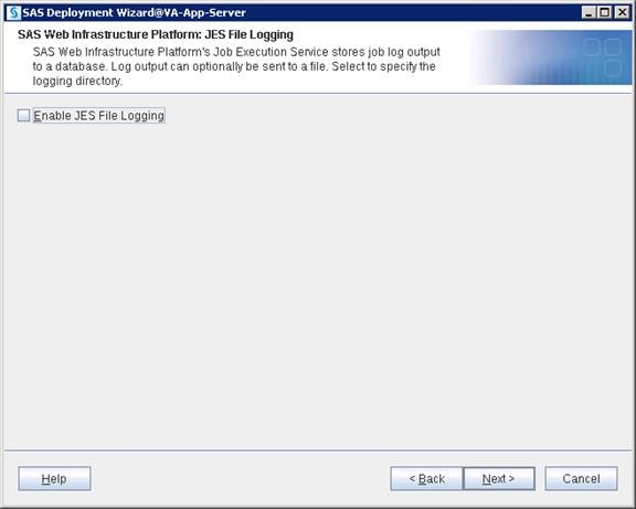
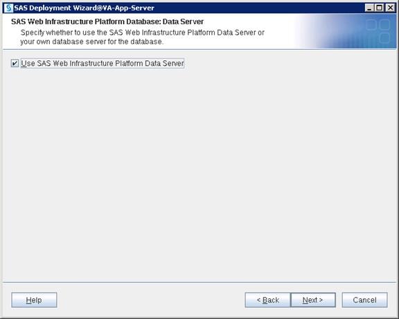
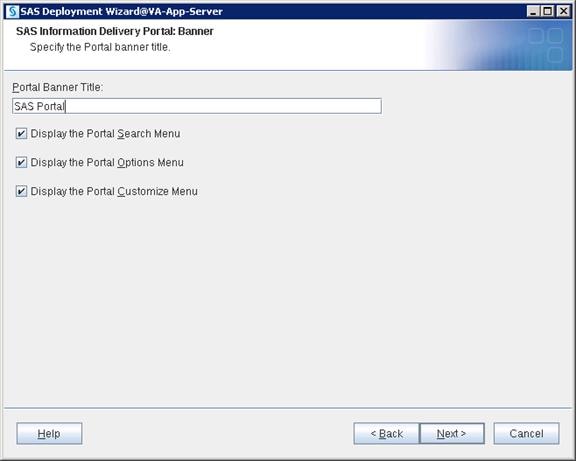
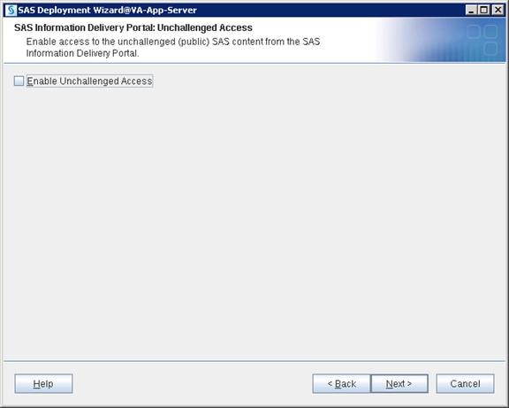


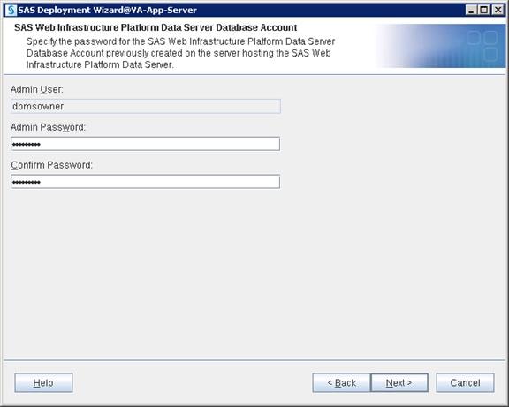
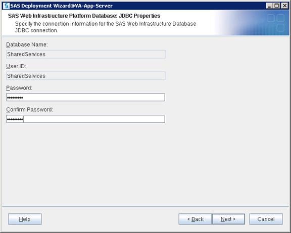
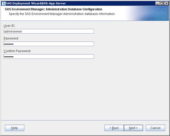
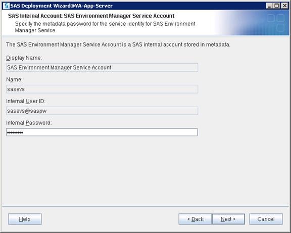
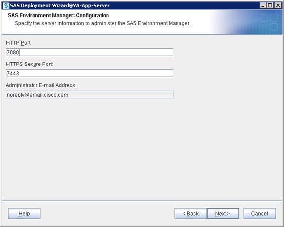

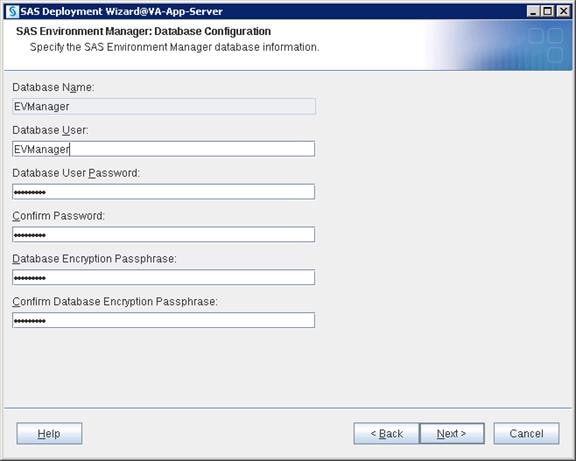
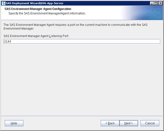


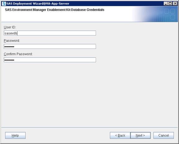
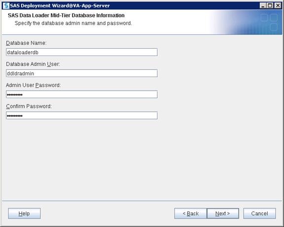
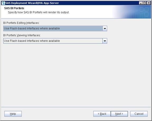
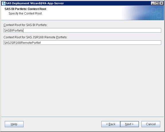
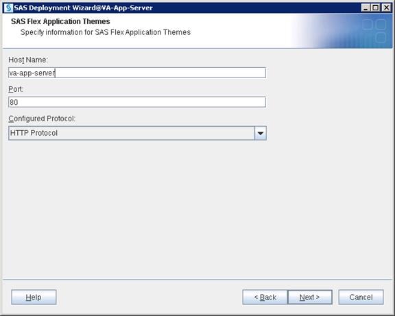
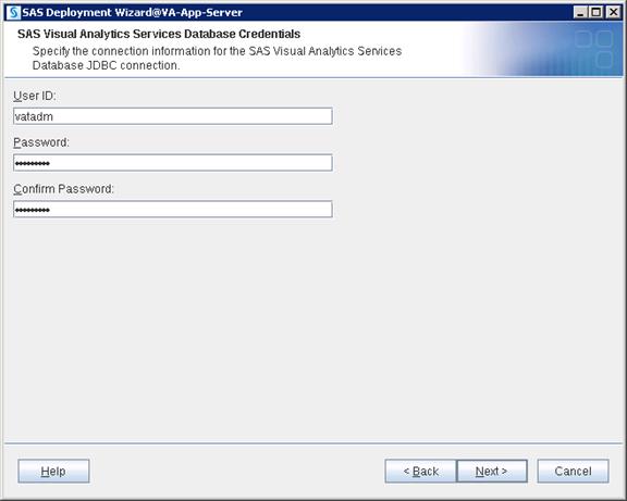
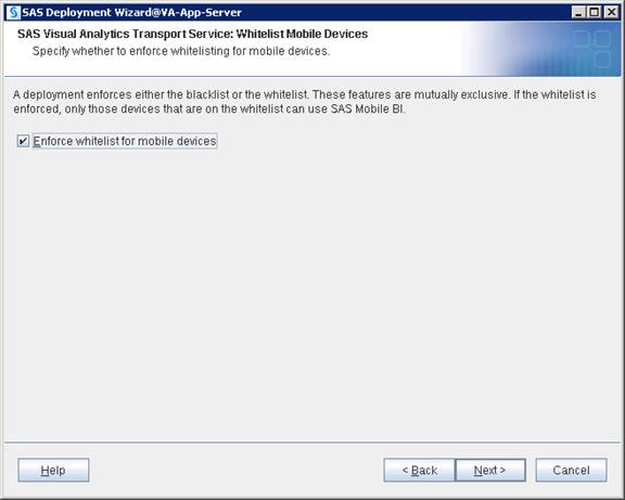
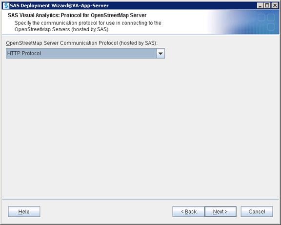
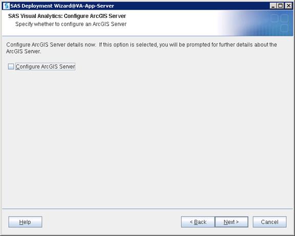


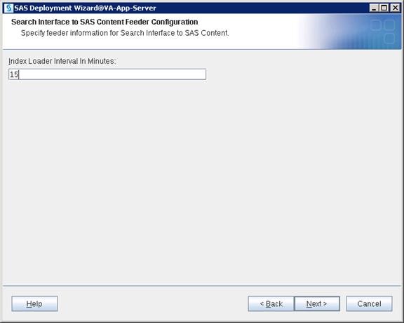

16. Select “Cloudera” for Hadoop Distribution. Click Next.

17. Select “Cloudera Manager” for cluster manager. Click Next.


18. Provide the admin credentials for Cloudera Manager. Click Next.
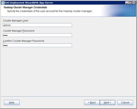
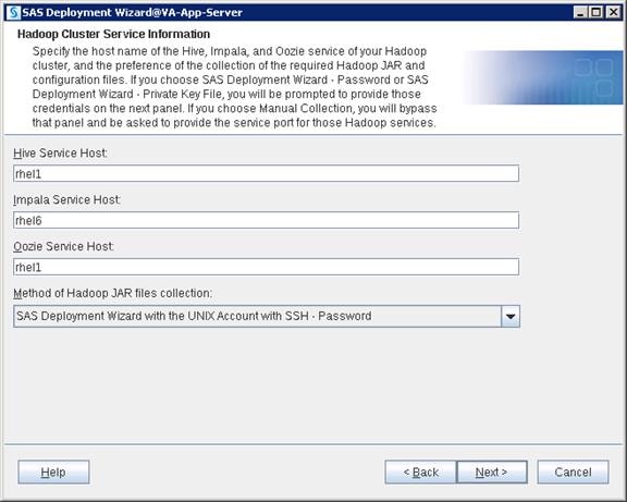
19. Provide the Root ID credentials. Click Next.
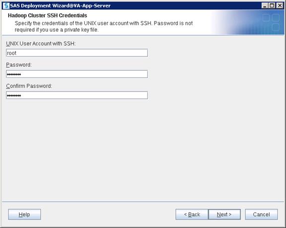
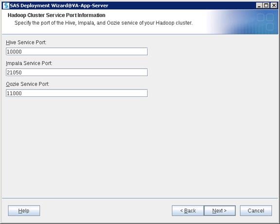
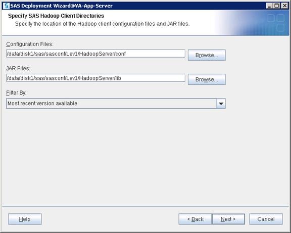
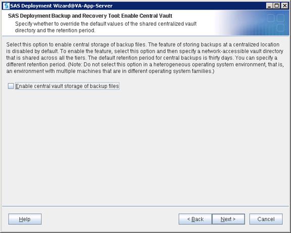
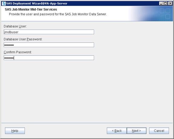
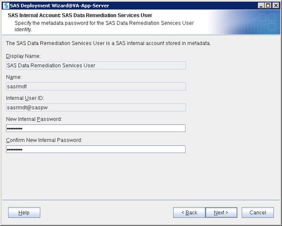
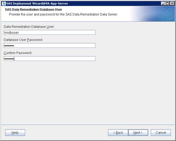
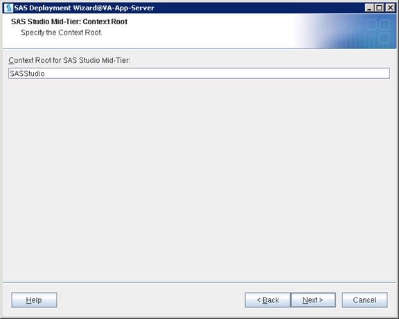
SAS Middle Tier uses Apache Tomcat which is incorporated in SAS. While installing Web Tier, /etc/opt/vmware/vfabric is the default location that Apache will try to place its license key files.
Therefore, the directory /etc/opt/vmware/vfabric must exist for the installation, with write access to the SAS installer ID.
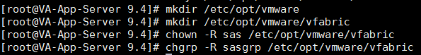
20. Click Start to begin the configuration.
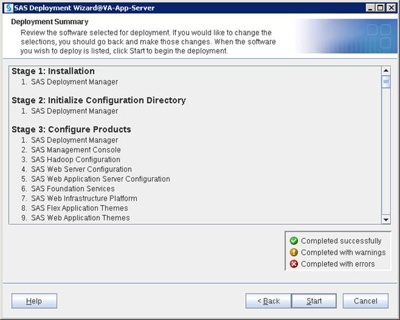
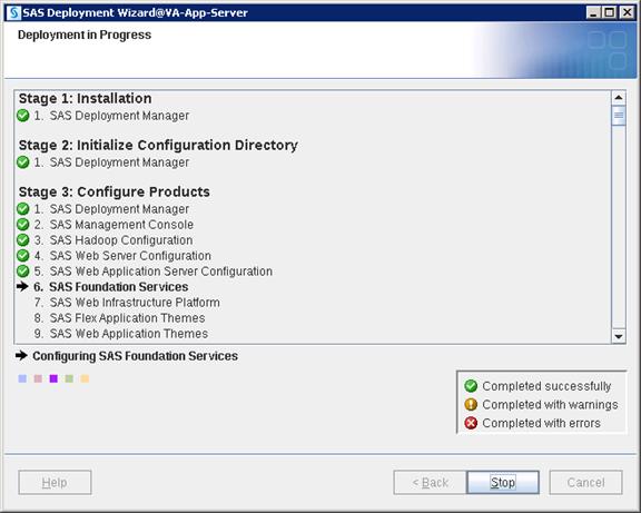
21. Click Next and then click Finish when the configuration completes.
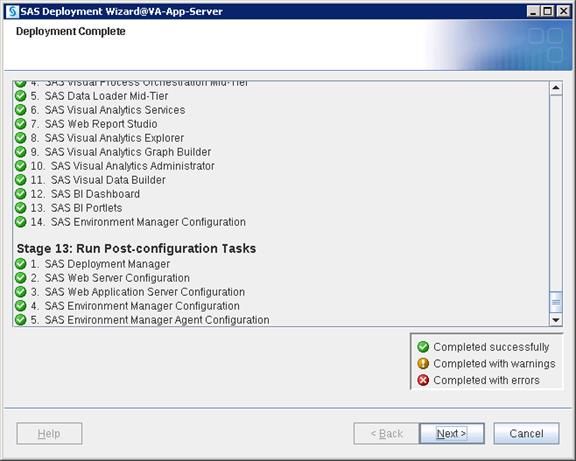
Cloudera Hadoop Configuration with SAS VA
Connect to the admin node (rhel1) using root or sas user and complete the following steps:
1. Copy hdatplugins.tar.gz file from /SASDepot_94_dist/standalone_installs/SAS_Plug-ins_for_Hadoop/1_0/Linux_for_x64 to /tmp.
2. Go to /tmp and untar the below file by running below command.
# tar xzf hdatplugins.tar.gz
![]()
3. Go to the /tmp/hdatplugins directory and run the ls command to list all the available files.
![]()
4. Copy all three .jar files to /opt/cloudera/parcels/CDH-5.7.0-1.cdh5.7.0.p0.45/lib/hadoop/lib on all LASR servers using simcp command.
Commands:
$ simcp /tmp/hdatplugins/sas.lasr.jar /opt/cloudera/parcels/CDH-5.7.0-1.cdh5.7.0.p0.45/lib/hadoop/lib
$ simcp /tmp/hdatplugins/sas.lasr.hadoop.jar /opt/cloudera/parcels/CDH-5.7.0-1.cdh5.7.0.p0.45/lib/hadoop/lib
$ simcp /tmp/hdatplugins/sas.grid.provider.yarn.jar /opt/cloudera/parcels/CDH-5.7.0-1.cdh5.7.0.p0.45/lib/hadoop/lib
5. Copy saslasrfd file to /opt/cloudera/parcels/CDH-5.7.0-1.cdh5.7.0.p0.45/lib/hadoop/bin location on all LASR servers using simcp command
$ simcp /tmp/hdatplugins/saslasrfd /opt/cloudera/parcels/CDH-5.7.0-1.cdh5.7.0.p0.45/lib/hadoop/bin
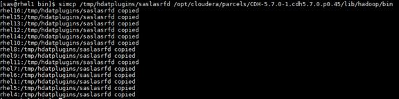
6. Log into Cloudera Manager and complete the following steps:
a. Open browser on admin node and connect to Cloudera Manager using the URL http://10.4.1.31:7180
b. Select HDFS > Configuration and search for “NameNode Plugins”. Add the following value: com.sas.lasr.hadoop.NameNodeService
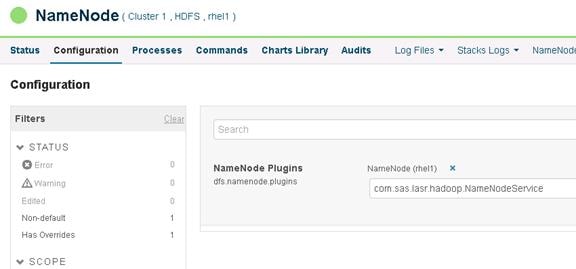
c. Select HDFS > Configuration and search for “DataNode Plugins”. Add the following value: com.sas.lasr.hadoop.DataNodeService
![]() Note: Make sure this applies to all the DataNodes.
Note: Make sure this applies to all the DataNodes.
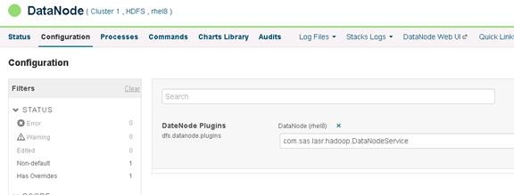
d. Select HDFS > Configuration and search for “HDFS Service Advanced Safety Valve” > select view as XML in the right pane then add the following value:
<property> <name>com.sas.lasr.service.allow.put</name> <value>true</value> </property> <property> <name>com.sas.lasr.hadoop.service.namenode.port</name> <value>15452</value> </property> <property> <name>com.sas.lasr.hadoop.service.datanode.port</name> <value>15453</value> </property> <property> <name> dfs.namenode.fs-limits.min-block-size</name> <value>0</value> </property>
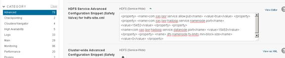
e. Restart all Cloudera services.
7. Edit the hosts file so the web browser can use the hostname for the URL. On Windows this is located here:
C:\Windows\System32\drivers\etc\hosts
8. Open a browser and connect to URL: http://va-app-server/SASVisualAnalyticsAdministrator or http://va-app-server/SASVisualAnalyticsAdministrator and log into SAS Visual Analytics Administrator with “lasradm” user.
9. Go to Tools --> Explore HDFS
This screen displays the available HDFS folders.
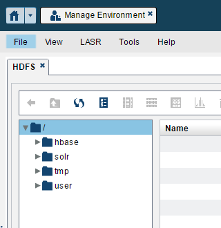
10. Create a test folder in hadoop with the user hdfs and make sure it is created.
$ hadoop fs -mkdir /test
![]()
$ hadoop fs -chmod 777 /test
![]()
$ hadoop fs -ls /
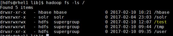
11. Go to SAS Visual Analytics Administrator > Tools > Explore HDFS.
![]() Note: Make sure you can see the “test” folder in HDFS.
Note: Make sure you can see the “test” folder in HDFS.
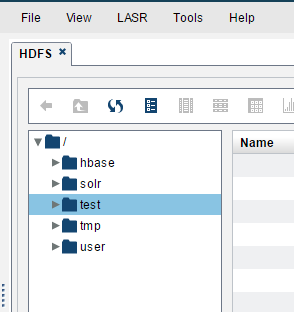
12. Select HDFS > Configuration and search for “HDFS Client Advanced Configuration Snippet (Safety Valve) for navigator.client.properties” > select hdfs-site.xml view as XML in the right pane. Add the following value:
<property> <name>com.sas.lasr.hadoop.service.namenode.port</name> <value>15452</value> </property>
<property> <name>com.sas.lasr.hadoop.service.datanode.port</name> <value>15453</value> </property>
<property> <name>dfs.datanode.data.dir</name> <value>file:///hadoop/hadoop-data</value> </property>
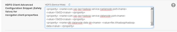
13. Select HDFS > Configuration and search for “HDFS Client Environment Advanced Configuration Snippet (Safety Valve) for hadoop-env.sh” > select View as XML in the right pane, then add the following value:
JAVA_HOME=/usr/java/jdk1.7.0_67-cloudera
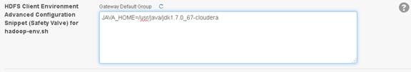
14. Restart all Cloudera services to deploy the configuration to all hosts.
Configure SAS Access for Hadoop
To configure SAS Access for Hadoop, complete the following steps:
1. Connect to va-compute server and run SAS Deployment Manager tool using following script.
$ /data/disk1/sas/sashome/SASDeploymentManager/9.4/sasdm.sh
![]()
2. Choose Language and click OK.
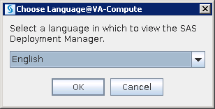
3. Select “Configure Hadoop Client Files” and click Next.
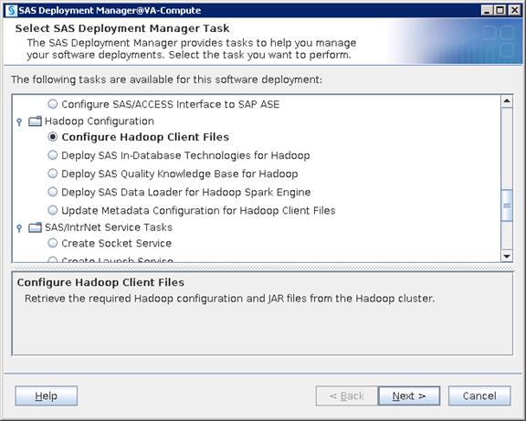
4. Select Hadoop Distribution as “Cloudera” and click Next.
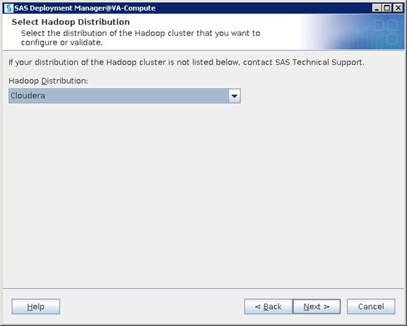
5. Select “Cloudera Manager” as Cluster Manager and click Next.

6. Provide the hostname Namenode and click Next.
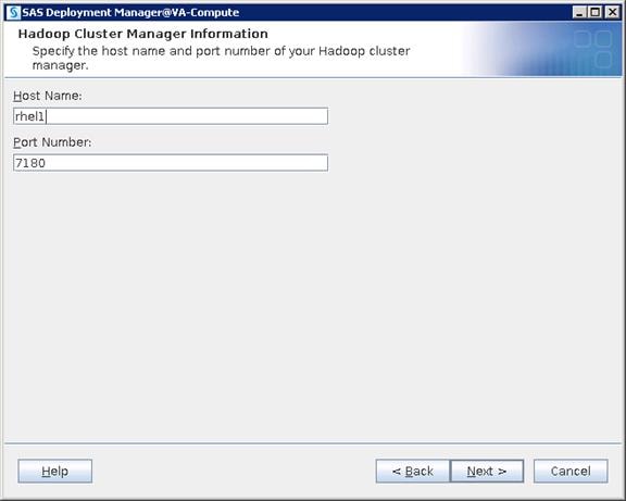
7. Provide the admin user ID and password that is the same user login to Cloudera Manager and click Next.
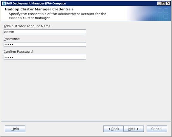
8. The Hadoop Cluster Service information automatically loads. Click Next.
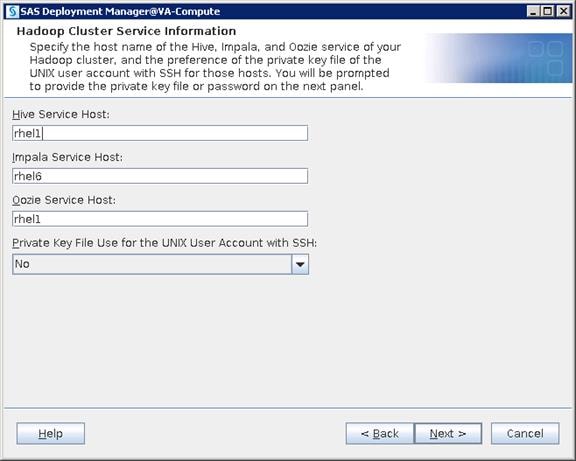
9. Provide the user ID and password that is used for deploying Cloudera Hadoop.
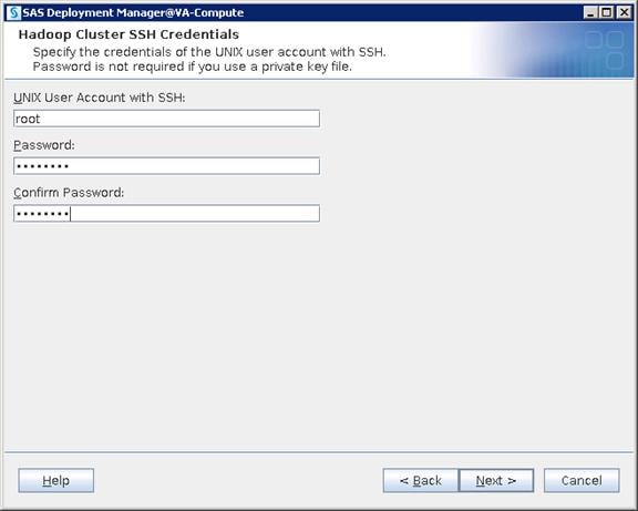
10. Provide the Cluster Service Port information.

11. Provide the configuration files and Jar files location. Click Next.
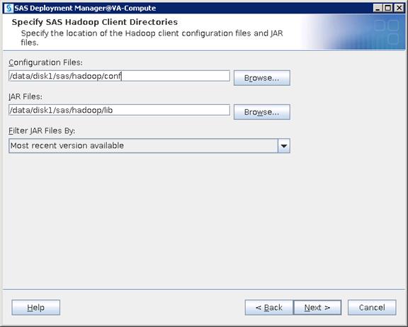
12. Check the box for Add environment variables. Click Next.

13. Check the box for validating “SAS/Access Interface to Hadoop”. Click Next.
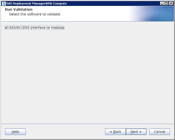
14. Enter default as the schema name for Hive and click Next.

15. Enter “hive” as the user and password. Click Next.
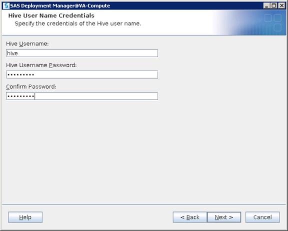
16. Click Next.

17. Click Start to configure.
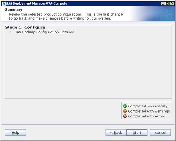

18. Click Next when the configuration is done.
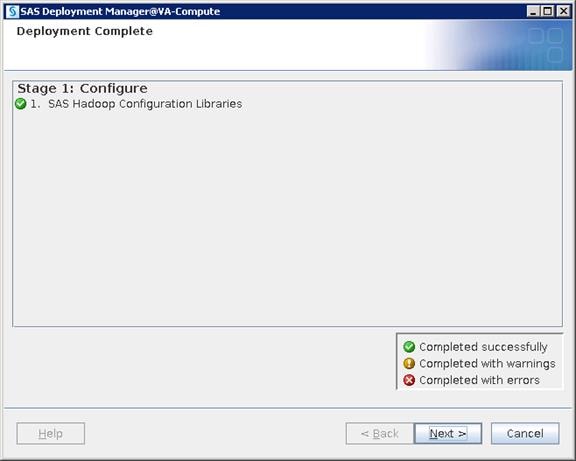
19. Click Finish.
Monitoring LASR Servers
To monitor LASR servers, complete the following steps:
1. Go to SAS Visual Analytics Administrator using the link below and login with lasradm user.
http://va-app-server/SASVisualAnalyticsAdministrator
2. Go to LASR > "Manage Servers" and check status of LASR servers.
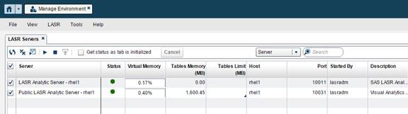
Monitoring LASR Tables
To monitor LASR tables, complete the following steps:
1. Go to LASR > "Manage Tables" and check status of LASR tables.
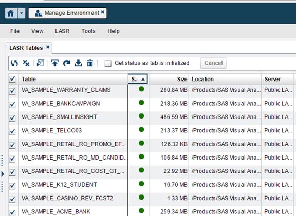
SAS Visual Analytics Sample Report Validation
1. Logon to Visual Analytics Report Viewer using below URL with lasradm user.
http://va-app-server/SASVisualAnalyticsViewer
2. Go to "Browse > Products > SASVisuall Analytics > Samples" and run any report.
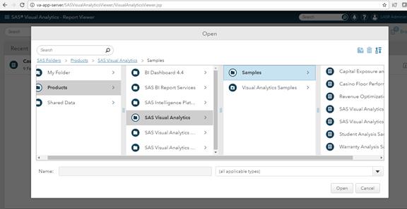
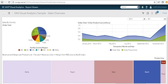
SAS Servers Status through SAS Environment Manager
1. Logon to SAS Environment Manager using the URL below with sasadm@saspw as the user.
2. Go to Resources and click Servers and see if the status of all the servers are green.
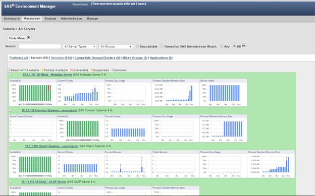
3. Check the box “Unavailable” and run by clicking the highlighted button. You should not see any servers listed under the Unavailable status.
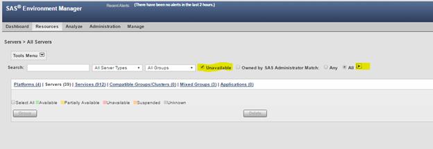
Validating Servers through SAS Management Console
1. Open SAS Management Console(SMC) using the script below from any SAS Tier installation. In this example, it is opened from Middle Tier server(VA-App-Server).
2. SMC can be opened from your client machine/desktop too, if it is installed. Go to "Start > All Programs > SAS > SAS Management Console 9.4" on a Windows machine.
![]()
3. Create a new connection profile.
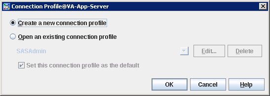
4. Click Next in the Connection Profile Wizard.
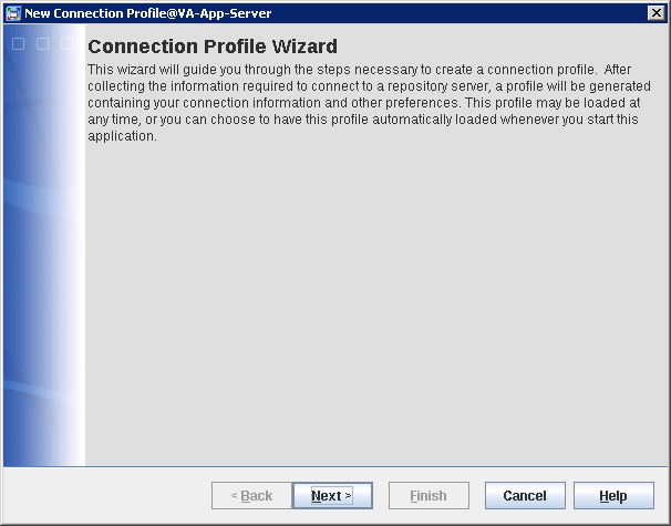
5. Provide a name for the connection profile and click Next.
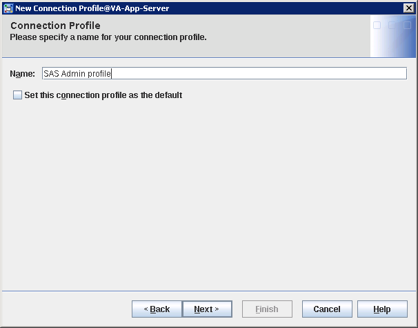
6. Provide the connection details as shown below and click Next.
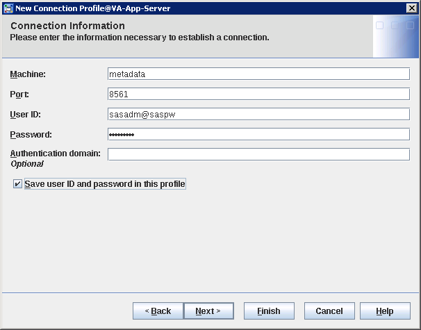
7. Check the connection details and click Finish.
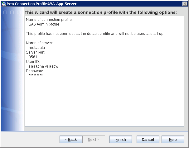
8. Expand the Server Manager Plugin > SASMeta > right-click "SASMeta - Logical Metadata Server" > Validate.
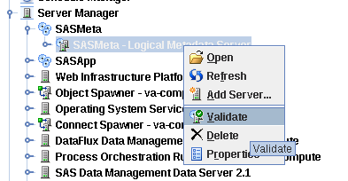
9. Enter sasdemo as the user ID and password when prompted and click OK.
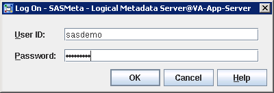
10. The Validation Successful screen appears. Click OK.

11. Expand Server Manager Plugin > SASApp > SASApp - Logical Connect Server > right-click "SASApp - Connect Server" > Validate.
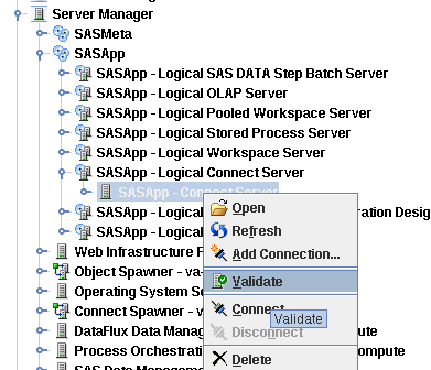
12. Expand the Server Manager Plugin > SASApp > SASApp - Logical Stored Process Server > SASApp - Stored Process Server > right-click "va-compute" > Validate.
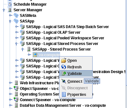
13. Expand Server Manager Plugin > SASApp > SASApp - Logical Workspace Server > SASApp - Workspace Server > right-click "va-compute" > Validate.
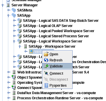
14. Expand Server Manager Plugin > SASApp > SASApp - Logical Pooled Workspace Server > SASApp - Pooled Workspace Server > right-click "va-compute" > Validate.
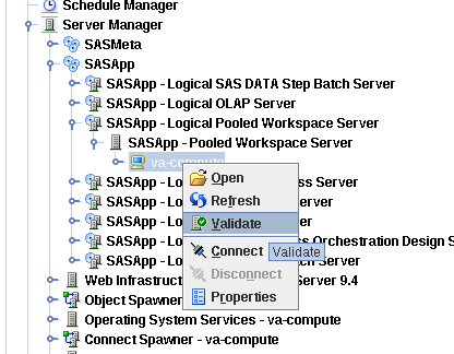
15. Go to Server Manager Plugin > right-click Operating System Services - va-compute > Validate.
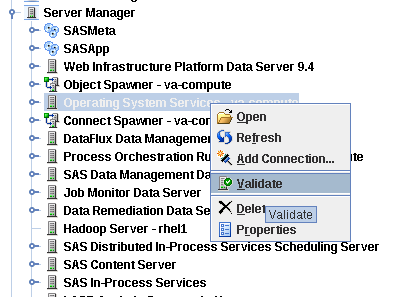
16. Go to the Server Manager Plugin > right-click SAS Content Server > Validate.
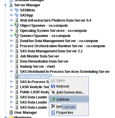
Check SAS Servers Status on Linux Servers
1. Logon to the metadata server with "sas" as the user and run the following script.
$ /data/disk1/sas/sasconf/Lev1/sas.servers status
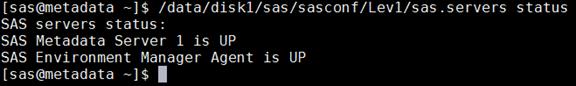
2. Logon to the va-compute server with "sas" as the user and run the following script.
$ /data/disk1/sas/sasconf/Lev1/sas.servers status
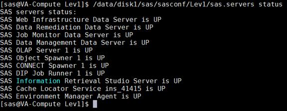
3. Logon to va-app-server with "sas" as the user and run the following script.
$ /data/disk1/sas/sasconf/Lev1/sas.servers status
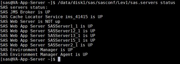
This section provides the Bill of Material for this solution.
Table 10 Bill of Materials for Hadoop / LASR Nodes
Table 11 Bill of Materials for SAS Visual Analytics Nodes
| Part Number |
Description |
Quantity |
| UCSC-C240-M4SX |
UCS C240 M4 SFF 24 HD w/o CPU, memory, HD, PCIe, PS, rail kit w/expander |
3 |
| UCSC-SAS12GHBA |
Cisco 12G SAS Modular Raid Controller |
3 |
| UCSC-MLOM-C40Q-03 |
Cisco VIC 1387 Dual Port 40Gb QSFP CNA MLOM |
3 |
| CAB-9K12A-NA |
Power Cord 125VAC 13A NEMA 5-15 Plug North America |
6 |
| UCSC-PSU2V2-1200W |
1200W/800W V2 AC Power Supply for 2U C-Series Servers |
6 |
| UCSC-RAILB-M4 |
Ball Bearing Rail Kit for C240 M4 rack servers |
3 |
| UCSC-HS-C240M4 |
Heat Sink for UCS C240 M4 Rack Server |
6 |
| N20-BBLKD |
UCS 2.5 inch HDD blanking panel |
48 |
| UCS-CPU-E52690E |
2.60 GHz E5-2690 v4/135W 14C/35MB Cache/DDR4 2400MHz |
6 |
| UCS-ML-1X324RV-A |
32GB DDR4-2400-MHz LRDIMM/PC4-19200/quad rank/x4/1.2v |
48 |
| UCS-SD16TBKS4-EV |
1.6TB 2.5 inch Enterprise Value 6G SATA SSD |
24 |
| UCS-SD240GBKS4-EB |
240 GB 2.5 inch Enterprise Value 6G SATA SSD (BOOT) |
6 |
| UCSC-PCI-1C-240M4 |
Right PCI Riser Bd (Riser 1) 2onbd SATA bootdrvs+ 2PCI slts |
3 |
| RACK-UCS2 |
Cisco R42610 standard rack w/side panels |
1 |
| RP208-30-1P-U-2= |
Cisco RP208-30-U-2 Single Phase PDU 20x C13 4x C19 (Country Specific) |
2 |
| CON-UCW3-RPDUX |
UC PLUS 24X7X4 Cisco RP208-30-U-X Single Phase PDU 2x (Country Specific) |
6 |
| CON-OSP-C240M4SX
|
SNTC-24X7X4OS UCS C240 M4 SFF 24 HD w/o CPU,mem
|
3 |
Table 12 Bill of Materials for Cisco UCS Fabric Interconnect 6332
| Part Number |
Description |
Quantity |
| UCS-SP-FI6332 |
(Not sold standalone) UCS 6332 1RU FI/No PSU/32 QSFP+ |
2 |
| UCS-PSU-6332-AC |
UCS 6332 Power Supply/100-240VAC |
4 |
| CAB-9K12A-NA |
Power Cord, 125VAC 13A NEMA 5-15 Plug, North America |
4 |
| QSFP-H40G-CU3M |
40GBASE-CR4 Passive Copper Cable, 3m |
16 |
| QSFP-H40G-CU3M |
40GBASE-CR4 Passive Copper Cable, 3m |
32 |
| UCS-LIC-6300-40GC |
3rd Gen FI Per port License to connect C-direct only |
32 |
| QSFP-40G-SR-BD |
QSFP40G BiDi Short-reach Transceiver |
8 |
| N10-MGT014 |
UCS Manager v3.1 |
2 |
| UCS-FAN-6332 |
UCS 6332 Fan Module |
8 |
| UCS-ACC-6332 |
UCS 6332 Chassis Accessory Kit |
2 |
Table 13 Red Hat Enterprise Linux License
| Red Hat Enterprise Linux |
||
| RHEL-2S2V-3A |
Red Hat Enterprise Linux |
22 |
| CON-ISV1-EL2S2V3A |
3 year Support for Red Hat Enterprise Linux |
22 |
| Cloudera Software edition needed for this CVD |
||
| Cloudera Enterprise Flex Edition |
UCS-BD-CEDHC-BZ= |
19 |
| Cloudera Enterprise Data Hub Edition |
UCS-BD-CEDHC-GD= |
19 |
Table 15 Cloudera SKU’s Available at Cisco
| Cisco TOP SKU |
Cisco PID with Duration |
Product Name |
| UCS-BD-CEBN-BZ= |
UCS-BD-CEBN-BZ-3Y |
Cloudera Enterprise Basic Edition, Node License, Bronze Support - 3 Year |
| UCS-BD-CEBN-BZI= |
UCS-BD-CEBN-BZI-3Y |
Cloudera Enterprise Basic Edition + Indemnification, Node License, Bronze Support - 3 Year |
| UCS-BD-CEBN-GD= |
UCS-BD-CEBN-GD-3Y |
Cloudera Enterprise Basic Edition, Node License, Gold Support - 3 Year |
| UCS-BD-CEBN-GDI= |
UCS-BD-CEBN-GDI-3Y |
Cloudera Enterprise Basic Edition + Indemnification, Node License, Gold Support - 3 Year |
| UCS-BD-CEDEN-BZ= |
UCS-BD-CEDEN-BZ-3Y |
Cloudera Enterprise Data Engineering Edition, Node License, Bronze Support - 3 Year |
| UCS-BD-CEDEN-GD= |
UCS-BD-CEDEN-GD-3Y |
Cloudera Enterprise Data Engineering Edition, Node License, Gold Support - 3 Year |
| UCS-BD-CEODN-BZ= |
UCS-BD-CEODN-BZ-3Y |
Cloudera Enterprise Operational Database Edition, Node License, Bronze Support - 3 Year |
| UCS-BD-CEODN-GD= |
UCS-BD-CEODN-GD-2Y |
Cloudera Enterprise Operational Database Edition, Node License, Gold Support - 2 Year |
| UCS-BD-CEODN-GD= |
UCS-BD-CEODN-GD-3Y |
Cloudera Enterprise Operational Database Edition, Node License, Gold Support - 3 Year |
| UCS-BD-CEADN-BZ= |
UCS-BD-CEADN-BZ-3Y |
Cloudera Enterprise Analytical Database Edition, Node License, Bronze Support - 3 Year |
| UCS-BD-CEADN-GD= |
UCS-BD-CEADN-GD-3Y |
Cloudera Enterprise Analytical Database Edition, Node License, Gold Support - 3 Year |
| UCS-BD-CEDHN-BZ= |
UCS-BD-CEDHN-BZ-3Y |
Cloudera Enterprise Data Hub Edition, Node License, Bronze Support - 3 Year |
| UCS-BD-CEDHN-GD= |
UCS-BD-CEDHN-GD-3Y |
Cloudera Enterprise Data Hub Edition, Node License, Gold Support - 3 Year |
| UCS-BD-CEBC-BZ= |
UCS-BD-CEBC-BZ-3Y |
Cloudera Enterprise Basic Edition, Capacity License, Bronze Support - 3 Year |
| UCS-BD-CEBC-BZI= |
UCS-BD-CEBC-BZI-3Y |
Cloudera Enterprise Basic Edition + Indemnification, Capacity License, Bronze Support - 3 Year |
| UCS-BD-CEBC-GD= |
UCS-BD-CEBC-GD-3Y |
Cloudera Enterprise Basic Edition, Capacity License, Gold Support - 3 Year |
| UCS-BD-CEBC-GDI= |
UCS-BD-CEBC-GDI-3Y |
Cloudera Enterprise Basic Edition + Indemnification, Capacity License, Gold Support - 3 Year |
| UCS-BD-CEDEC-BZ= |
UCS-BD-CEDEC-BZ-3Y |
Cloudera Enterprise Data Engineering Edition, Capacity License, Bronze Support - 3 Year |
| UCS-BD-CEDEC-GD= |
UCS-BD-CEDEC-GD-3Y |
Cloudera Enterprise Data Engineering Edition, Capacity License, Gold Support - 3 Year |
| UCS-BD-CEODC-BZ= |
UCS-BD-CEODC-BZ-3Y |
Cloudera Enterprise Operational Database Edition, Capacity License, Bronze Support - 3 Year |
| UCS-BD-CEODC-GD= |
UCS-BD-CEODC-GD-3Y |
Cloudera Enterprise Operational Database Edition, Capacity License, Gold Support - 3 Year |
| UCS-BD-CEADC-BZ= |
UCS-BD-CEADC-BZ-3Y |
Cloudera Enterprise Analytical Database Edition, Capacity License, Bronze Support - 3 Year |
| UCS-BD-CEADC-GD= |
UCS-BD-CEADC-GD-3Y |
Cloudera Enterprise Analytical Database Edition, Capacity License, Gold Support - 3 Year |
| UCS-BD-CEDHC-BZ= |
UCS-BD-CEDHC-BZ-3Y |
Cloudera Enterprise Data Hub Edition, Capacity License, Bronze Support - 3 Year |
| UCS-BD-CEDHC-GD= |
UCS-BD-CEDHC-GD-3Y |
Cloudera Enterprise Data Hub Edition, Capacity License, Gold Support - 3 Year |
Manan Trivedi, Big Data Solutions Architect, Data Center Solutions Group, Cisco Systems, Inc.
Manan's main focus areas are architecture, solutions, and emerging trends in Big Data related technologies, infrastructure, and performance.
Vadiraja Bhatt, Principal Engineer, Emerging Technology Solutions, Cisco UCS Group, Cisco Systems, Inc.
Vadi leads the Cisco UCS Analytics and Big Data solutions in India. He has more than 20 years of experience developing and architecting Enterprise solutions. Vadi’s expertise includes Enterprise Database design, Enterprise application design, and performance engineering. His team has been designing and developing best practices and various enterprise applications solutions on Cisco UCS. His team publishes industry standard benchmark numbers such as TPC and SPEC on the Cisco UCS platform. Prior to joining Cisco, Vadi was a Technical Director at SAP, focusing on database products ASE, IQ, and more, in the area of performance engineering. Vadi holds 6 US patents to his credit in the area of database design. He holds a Master’s degree from IIT, Mumbai in Computer Science and Engineering.
Acknowledgements
· Ted Wu, System Engineer, Data Center Solutions Group, Cisco Systems, Inc.
· Shane Handy, Big Data Solutions Architect, Data Center Solutions Group, Cisco Systems, Inc.
· Sathya Mantena, Technical Consultant, CoreCompete
· Nageswara Sastry Ganduri, Senior Technical Architect, CoreCompete
 Feedback