- Preface
- Using the Cisco TelePresence System Administration
- Device Information
- Configuring the Cisco TelePresence System
- Troubleshooting the CTS 500
- Troubleshooting the CTS 500-32 and CTS 500-37
- Troubleshooting the CTS 1000
- Troubleshooting the CTS 1100
- Troubleshooting the CTS 1300
- Troubleshooting the TX1300 47
- Troubleshooting the CTS 3000 and CTS 3200
- Troubleshooting the CTS 3010 and CTS 3210
- Monitoring the Cisco TelePresence System
- Satellite Licenses for the Cisco TelePresence System
- Glossary
- Index
- Contents
- Managing CTS 500 Hardware Setup
Troubleshooting the CTS 500
Contents
You may want to periodically test system components using the hardware and software tests available in the Cisco TelePresence System (CTS) Administration Troubleshooting window. This chapter contains information about troubleshooting CTS 500 hardware and software.
Before You Begin
1. ![]() Obtain your IP address in one of the following ways:
Obtain your IP address in one of the following ways:
–![]() From the CTS Cisco Unified IP phone touch the following softkeys:
From the CTS Cisco Unified IP phone touch the following softkeys:
Manual > more > Info

Tip ![]() If you have more options on your phone, touch the more softkey until you reach the end of the selections.
If you have more options on your phone, touch the more softkey until you reach the end of the selections.
–![]() From the Cisco TelePresence Touch 12 tap the following:
From the Cisco TelePresence Touch 12 tap the following:
More > Status > System Status
2. ![]() Make a note of the IP address.
Make a note of the IP address.
3. ![]() Enter the IP address in your laptop's browser window.
Enter the IP address in your laptop's browser window.
4. ![]() Click Yes to accept all security connection messages.
Click Yes to accept all security connection messages.

Note ![]() You cannot perform diagnostics during an active Cisco TelePresence system call.
You cannot perform diagnostics during an active Cisco TelePresence system call.
Proceed to the following sections to troubleshoot system components:
•![]() Managing CTS 500 Hardware Setup
Managing CTS 500 Hardware Setup
•![]() Testing the Network Connection
Testing the Network Connection
•![]() Managing Configuration Issues
Managing Configuration Issues
•![]() Troubleshooting Video Quality Settings
Troubleshooting Video Quality Settings
•![]() Troubleshooting Network Cabling
Troubleshooting Network Cabling
Managing CTS 500 Hardware Setup
You can manage and test the following Cisco TelePresence System components:
Before You Begin
Before you begin testing and troubleshooting your system, check the system displays. All of the Cisco TelePresence System Administration interface Hardware Setup features require the use of the displays in the meeting room. Therefore, we recommend the following:
1. ![]() Verify that the displays work by using the Hardware Setup > Displays tests in this section.
Verify that the displays work by using the Hardware Setup > Displays tests in this section.
2. ![]() If the displays are showing the correct images, you can proceed to testing the cameras, speakers, and microphones, as needed.
If the displays are showing the correct images, you can proceed to testing the cameras, speakers, and microphones, as needed.
Note ![]() You must test the speakers before testing the microphones because the microphone test depends on speakers that are functioning properly. See the "Testing Speakers" section.
You must test the speakers before testing the microphones because the microphone test depends on speakers that are functioning properly. See the "Testing Speakers" section.
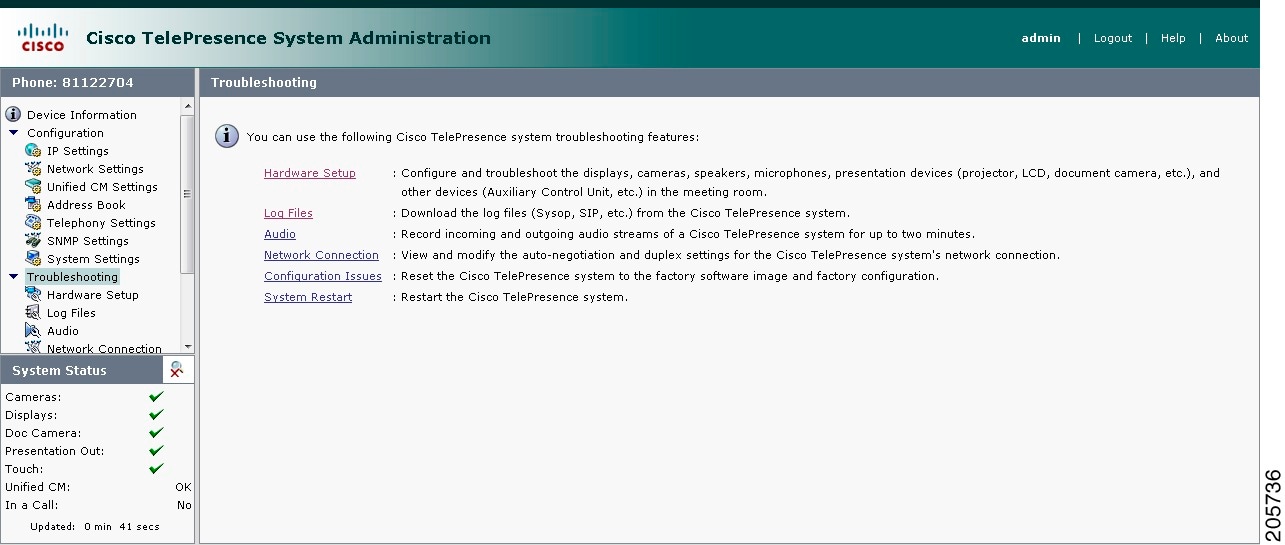
Figure 4-1 shows the Cisco TelePresence System administration tools available to assist you with troubleshooting tasks.
Figure 4-1 Troubleshooting Window
Managing Displays
A display is set up successfully when the color on the display has been adjusted for the lighting in the meeting room.
Note ![]() Each display must be adjusted individually.
Each display must be adjusted individually.
Use the information in the following sections to adjust the display for your system:
Selecting the Light Level
When adjusting the images on the CTS display screens, you must take the color temperature of the ambient light in the room into consideration.
Sources of light in most rooms are produced by fluorescent fixtures or incandescent light bulbs that use tungsten filaments. Each of these light sources, and the amount of light in terms of lumens or watts, produces a different color temperature. This color temperature is sometimes expressed using terms such cool, warm, or daylight, but can be expressed more precisely in kelvins (K) as a numeric value.
The following temperatures can be selected for adjusting the image on the Cisco TelePresence display screens:
•![]() 3500 K
3500 K
•![]() 4000/4100 K (recommended)
4000/4100 K (recommended)
•![]() 5000 K
5000 K
•![]() 6500 K
6500 K
•![]() 7500 K
7500 K
Tip ![]() In many cases, the color temperature is printed on the light bulb. If you are unable to ascertain the type and color temperature of light bulbs in the meeting room, experiment with color temperature settings until the color and images on the display screen look lifelike.
In many cases, the color temperature is printed on the light bulb. If you are unable to ascertain the type and color temperature of light bulbs in the meeting room, experiment with color temperature settings until the color and images on the display screen look lifelike.
Tip ![]() It is OK to try a few different color temperatures to see what looks best in the room. Remember, the Color Temperature setting only effects how the local participants see the display, it does not effect the way the room looks to remote participants.
It is OK to try a few different color temperatures to see what looks best in the room. Remember, the Color Temperature setting only effects how the local participants see the display, it does not effect the way the room looks to remote participants.
Adjusting Your Display
To adjust a display:
Step 1 ![]() Log in to the Cisco TelePresence System Administration interface.
Log in to the Cisco TelePresence System Administration interface.
Step 2 ![]() Choose Troubleshooting > Hardware Setup.
Choose Troubleshooting > Hardware Setup.
Step 3 ![]() Click the Displays radio button. A test image appears.
Click the Displays radio button. A test image appears.
Step 4 ![]() Click Start in the Testing box to start the adjustment process. The Current Color Temperature test screen appears, as shown in Figure 4-2.
Click Start in the Testing box to start the adjustment process. The Current Color Temperature test screen appears, as shown in Figure 4-2.
Note ![]() Each display in the meeting room should be showing a set of horizontal grey bars and that display's relative position. The current color temperature setting is displayed.
Each display in the meeting room should be showing a set of horizontal grey bars and that display's relative position. The current color temperature setting is displayed.
Figure 4-2 Color Temperature Test Screen

Step 5 ![]() Select the color temperature of the lighting in the meeting room from the drop-down menu. The Apply button is activated.
Select the color temperature of the lighting in the meeting room from the drop-down menu. The Apply button is activated.
Step 6 ![]() Click Apply.
Click Apply.
Step 7 ![]() Click Stop to stop the test.
Click Stop to stop the test.
Troubleshooting Displays
Use the information in Table 4-1 to troubleshoot images on the displays.
|
|
|
|
|---|---|---|
No image. |
• • |
Check power connections and switches on each display. |
The display has no image when you are between calls. |
No image expected. Enable a display test from the Web user interface to place the displays in test mode. |
|
Cable is not connected or is connected to the wrong HDMI port in the display |
Confirm that the HDMI cable is plugged into the Main input (white) and not the Auxiliary input (orange). Contact Cisco technical support if you are certain that the cabling is correct and power is applied to the system, but no image is seen on the display. See the Routing Power and Signal Cables section in the Cisco TelePresence System 500 Assembly, Use & Care, and Field Replacement Unit Guide. |
Related Information
•![]() For more information about setting up and testing displays, see the Cisco TelePresence System 500 Assembly, Use & Care, and Field Replacement Unit Guide.
For more information about setting up and testing displays, see the Cisco TelePresence System 500 Assembly, Use & Care, and Field Replacement Unit Guide.
•![]() For more system troubleshooting information, see the Cisco TelePresence System Troubleshooting Guide on Cisco.com.
For more system troubleshooting information, see the Cisco TelePresence System Troubleshooting Guide on Cisco.com.
Testing Cameras
The cameras are set up successfully when images are centered and in focus on the display screens and the white balance has been configured. The hardware setup software provides a camera Auto Adjust feature and a way to use targets to fine-tune the camera's focus.
Note ![]() You must use the camera Auto Adjust feature before you can auto focus the camera. See the "Auto Adjusting the Camera" section.
You must use the camera Auto Adjust feature before you can auto focus the camera. See the "Auto Adjusting the Camera" section.
Use the information in the following sections to test and troubleshoot the camera for your system:
Note ![]() The camera hood comes off. It should be removed and left off until these procedures are complete.
The camera hood comes off. It should be removed and left off until these procedures are complete.
Testing the CTS 500 Camera
The following sections describe how to set up the CTS 500 camera for testing:
•![]() Setting up the Camera Targets
Setting up the Camera Targets
•![]() Reattaching the Camera Haze and Replacing the Hood
Reattaching the Camera Haze and Replacing the Hood
Removing the Camera Hood
Removing the camera hood provides access to the zoom and focus rings for the camera. The entire camera hood and speaker cover attachment comes off in one piece. To remove the camera hood.
Step 1 ![]() Pull the top of the hood towards you until that portion of the hood snaps open.
Pull the top of the hood towards you until that portion of the hood snaps open.
Step 2 ![]() Pull the bottom of the hood until the entire unit snaps off of the camera.
Pull the bottom of the hood until the entire unit snaps off of the camera.
Setting up the Camera Targets
To set up the camera target:
Step 1 ![]() Prepare the large camera target and place it on the easel.
Prepare the large camera target and place it on the easel.
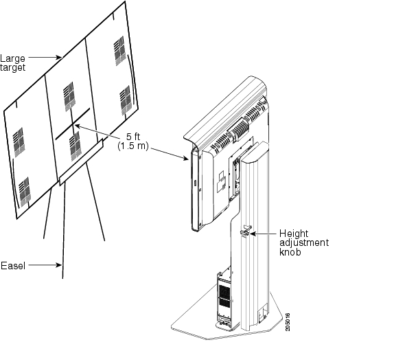
Step 2 ![]() Set the easel and large target in the position that the user will occupy. Use the distance measured from the camera to the head of the user to position the target. If the distance is unknown, use 1.5 meters (5 feet).
Set the easel and large target in the position that the user will occupy. Use the distance measured from the camera to the head of the user to position the target. If the distance is unknown, use 1.5 meters (5 feet).
Testing the Camera
To set up the camera for testing.
Step 1 ![]() Log in to the Cisco TelePresence System Administration interface.
Log in to the Cisco TelePresence System Administration interface.
Step 2 ![]() Choose Troubleshooting > Hardware Setup.
Choose Troubleshooting > Hardware Setup.
Step 3 ![]() Click the Cameras radio button.
Click the Cameras radio button.
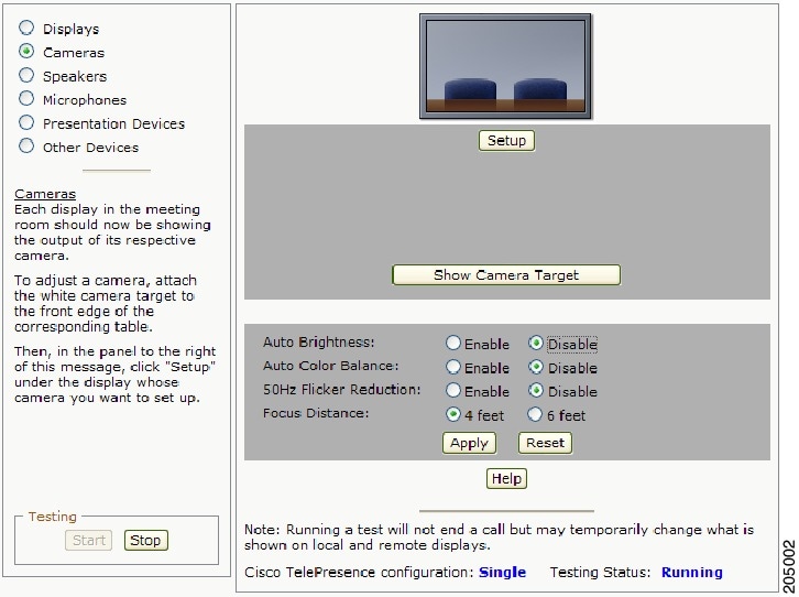
Step 4 ![]() Click Start. The display enters loopback mode. In loopback mode, the display shows images from the camera. The Camera Target testing options appear, as shown in Figure 4-3.
Click Start. The display enters loopback mode. In loopback mode, the display shows images from the camera. The Camera Target testing options appear, as shown in Figure 4-3.
Figure 4-3 Cameras Screen
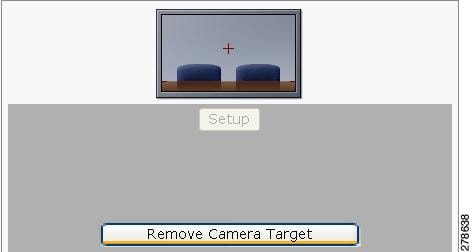
Step 5 ![]() Click Show Camera Target. A red + appears on the test screen, as shown in Figure 4-4.
Click Show Camera Target. A red + appears on the test screen, as shown in Figure 4-4.
Figure 4-4 Show Camera Target
Step 6 ![]() Prepare the large camera target and place it on the easel.
Prepare the large camera target and place it on the easel.
Step 7 ![]() Set the easel and large target in the position that the user will occupy. Use the distance measured from the camera to the head of the user to position the target. If the distance is unknown, use 1.5 meters (5 feet).
Set the easel and large target in the position that the user will occupy. Use the distance measured from the camera to the head of the user to position the target. If the distance is unknown, use 1.5 meters (5 feet).
Note ![]() The user must be at least 4 feet (1.2 meters) away from the display for all CTS 500 installations.
The user must be at least 4 feet (1.2 meters) away from the display for all CTS 500 installations.
Figure 4-5 shows a pedestal stand-mounted CTS 500. Use the same method for all types of CTS 500 installations.
Figure 4-5 Camera Target Placement
Step 8 ![]() Raise or lower the CTS 500 so that the green rectangle that displays on the screen is at the approximate eye level of the CTS 500 user.
Raise or lower the CTS 500 so that the green rectangle that displays on the screen is at the approximate eye level of the CTS 500 user.
Note ![]() If you have a wall-mounted CTS 500, skip this step.
If you have a wall-mounted CTS 500, skip this step.
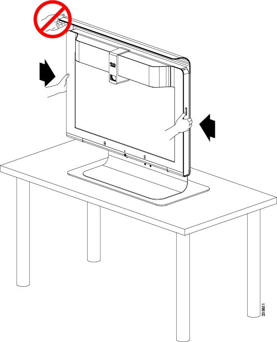
Use the following guidelines when raising and lowering the stand (see Figure 4-6 and Figure 4-7):
•![]() Do not grasp the light reflector, or any part of the CTS 500 but the monitor.
Do not grasp the light reflector, or any part of the CTS 500 but the monitor.
•![]() Use two hands.
Use two hands.
•![]() Do not lift using only one side.
Do not lift using only one side.
•![]() Apply equal pressure from each side.
Apply equal pressure from each side.
Figure 4-6 Height Adjustment Guidelines—Pedestal Stand-Mounted CTS-500
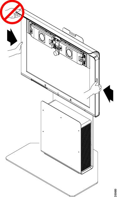
Figure 4-7 Height Adjustment Guidelines—Table Stand-Mounted CTS 500
Note ![]() If the user is available, use them to position the CTS 500. If the user is not available, or if the CTS 500 will be used by multiple people, use an average eye level height.
If the user is available, use them to position the CTS 500. If the user is not available, or if the CTS 500 will be used by multiple people, use an average eye level height.
Tip ![]() If you have a pedestal stand-mounted CTS 500 and applied the height sticker, you can use it to choose an approximate height. For more information about the height sticker, see the "Assembling a Pedestal Stand-Mounted CTS 500" chapter in the Cisco TelePresence System 500 Assembly, Use & Care, and Field Replaceable Unit Guide.
If you have a pedestal stand-mounted CTS 500 and applied the height sticker, you can use it to choose an approximate height. For more information about the height sticker, see the "Assembling a Pedestal Stand-Mounted CTS 500" chapter in the Cisco TelePresence System 500 Assembly, Use & Care, and Field Replaceable Unit Guide.
Step 9 ![]() Position the easel so the black plus sign (+) of the target is in the same position as the red plus sign
Position the easel so the black plus sign (+) of the target is in the same position as the red plus sign
(+) on the display.
Step 10 ![]() Adjust the camera so that the red + is centered on the white target and the hash marks at each side are aligned to the top of the table.
Adjust the camera so that the red + is centered on the white target and the hash marks at each side are aligned to the top of the table.
Tip ![]() You can raise and lower the large target by adjusting the legs of the easel or move the target slightly from side to side. However, do not move the easel from the position that the user will occupy. If possible, move the camera to accommodate the position of the easel.
You can raise and lower the large target by adjusting the legs of the easel or move the target slightly from side to side. However, do not move the easel from the position that the user will occupy. If possible, move the camera to accommodate the position of the easel.
Figure 4-8 shows a camera correctly adjusted.
Figure 4-8 Camera Adjustment
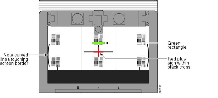
Step 11 ![]() Loosen the thumbscrew on the camera and twist the zoom ring on the lens until the curved lines on the left and right are just touching the left and right borders of the screen. Make sure the black plus sign
Loosen the thumbscrew on the camera and twist the zoom ring on the lens until the curved lines on the left and right are just touching the left and right borders of the screen. Make sure the black plus sign
(+) is still in the same position as the red plus sign (+). Tighten the thumbscrew when the adjustment is complete.
See Figure 4-8 for an example of correct zoom adjustment.
Step 12 ![]() Click Remove Camera Target to stop the test.
Click Remove Camera Target to stop the test.
Auto Adjusting the Camera
To tune the camera for brightness, color balance, and distance complete the steps in the following sections:
•![]() Understanding Camera Setup Choices for Room Lighting
Understanding Camera Setup Choices for Room Lighting
Note ![]() For more information about room lighting, see the "Testing the CTS 500 Camera" section.
For more information about room lighting, see the "Testing the CTS 500 Camera" section.
Fixed Artificial Lighting
If the room uses fixed artificial lighting:
Step 1 ![]() Click the Disable radio button for the following:
Click the Disable radio button for the following:
•![]() Camera Auto Brightness
Camera Auto Brightness
•![]() Camera Auto Color Balance
Camera Auto Color Balance
Step 2 ![]() Click Setup. A selection of options appear.
Click Setup. A selection of options appear.
Step 3 ![]() Click Auto Adjust to automatically adjust the lighting and color balance.
Click Auto Adjust to automatically adjust the lighting and color balance.
Note ![]() Make sure that the large target is still in place and that nothing is between the large target and the camera.
Make sure that the large target is still in place and that nothing is between the large target and the camera.
The camera calibrates and saves the settings. This process takes approximately 20 seconds.
Note ![]() If the test fails, you may need to add more light to the room.
If the test fails, you may need to add more light to the room.
Step 4 ![]() Click Show Focus Target. Red and green targets appear on the test screen.
Click Show Focus Target. Red and green targets appear on the test screen.
Note ![]() To remove the targets, click Hide Focus Target.
To remove the targets, click Hide Focus Target.
Step 5 ![]() With both white targets set up, adjust the camera focus so that the long red and green line are the same length.
With both white targets set up, adjust the camera focus so that the long red and green line are the same length.
Step 6 ![]() Click Done when you are finished making adjustments.
Click Done when you are finished making adjustments.
Step 7 ![]() If you require further adjustments to the room brightness, click the Enable radio button for the Camera Auto Brightness and Camera Auto Color Balance choices, then select a choice from the Luminance drop-down list until the brightness and contrast are at acceptable levels.
If you require further adjustments to the room brightness, click the Enable radio button for the Camera Auto Brightness and Camera Auto Color Balance choices, then select a choice from the Luminance drop-down list until the brightness and contrast are at acceptable levels.
Outside Lighting
If the room uses outside lighting, or has any other conditions that could cause variable room lighting:
Step 1 ![]() Click the Enable radio button for the following:
Click the Enable radio button for the following:
•![]() Camera Auto Brightness
Camera Auto Brightness
•![]() Camera Auto Color Balance
Camera Auto Color Balance
Note ![]() Auto Color Balance can produce undesirable results if the colors of the walls in your room are not white or gray.
Auto Color Balance can produce undesirable results if the colors of the walls in your room are not white or gray.
Step 2 ![]() To make additional adjustments to the camera brightness and contrast levels, select a choice from the Luminance drop-down list.
To make additional adjustments to the camera brightness and contrast levels, select a choice from the Luminance drop-down list.
Step 3 ![]() In the 50 Hz Flicker Reduction field, click the Disable radio button.
In the 50 Hz Flicker Reduction field, click the Disable radio button.
Note ![]() If you are in country that uses a 50 Hertz (Hz) power frequency (a country other than the USA, Canada or Mexico) and there is a noticeable flicker on the screen, click the Enable radio button in this field. If you enable the flicker reduction feature, the flicker is reduced or eliminated, but the image quality is reduced. To eliminate the flicker at its source, you can use an electronic ballast instead of a magnet ballast for the fluorescent lights at your installation. After you change the ballast for the fluorescent lights, you can click the Disable radio button in the 50 Hz Flicker Reduction field.
If you are in country that uses a 50 Hertz (Hz) power frequency (a country other than the USA, Canada or Mexico) and there is a noticeable flicker on the screen, click the Enable radio button in this field. If you enable the flicker reduction feature, the flicker is reduced or eliminated, but the image quality is reduced. To eliminate the flicker at its source, you can use an electronic ballast instead of a magnet ballast for the fluorescent lights at your installation. After you change the ballast for the fluorescent lights, you can click the Disable radio button in the 50 Hz Flicker Reduction field.
Understanding Camera Setup Choices for Room Lighting
If your room has windows that contribute a significant amount of natural light, you can set your CTS to automatically compensate for variable lighting conditions. This compensation is an average adjustment and will not be as accurate as the color settings you select for a room that uses fixed, artificial room lighting.
Table 4-2 contains recommendations for desirable display and camera settings when you set up the display and camera. See the "Testing the CTS 500 Camera" section for more information.
Focusing the Camera
The CTS 500 camera has vertical height, zoom, and focus adjustments. Adjust the camera using the following guidelines:
•![]() Using the camera test images that display on the screen, adjust the camera vertical height to set the eye level of the user at 70 percent of the total vertical height of the screen.
Using the camera test images that display on the screen, adjust the camera vertical height to set the eye level of the user at 70 percent of the total vertical height of the screen.
•![]() Using the large and small (far and near) targets that you set up in Setting up the Camera Targets, adjust the camera focus.
Using the large and small (far and near) targets that you set up in Setting up the Camera Targets, adjust the camera focus.
To focus the camera:
Step 1 ![]() Adjust the Focus Distance using these guidelines:
Adjust the Focus Distance using these guidelines:
•![]() If the user is 1.2 meters to 1.5 meters (4 to 5 feet) away from the display, click 4 feet.
If the user is 1.2 meters to 1.5 meters (4 to 5 feet) away from the display, click 4 feet.
•![]() If the user is farther than 1.5 meters (5 feet) away, click 6 feet.
If the user is farther than 1.5 meters (5 feet) away, click 6 feet.
Step 2 ![]() Click Apply.
Click Apply.
Step 3 ![]() Click Show Focus Targets.
Click Show Focus Targets.
Step 4 ![]() Reposition the targets by completing the following steps:
Reposition the targets by completing the following steps:
a. ![]() Lean the large target against a chair or other surface so that it is taller than it is wide.
Lean the large target against a chair or other surface so that it is taller than it is wide.
b. ![]() Move the large target 6 to 8 feet (1.8288 to 2.4384 meters) from the camera so that the red box encloses some of the patterns on the large target when you view the display, as shown in Figure 4-9.
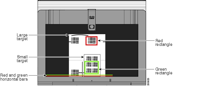
Move the large target 6 to 8 feet (1.8288 to 2.4384 meters) from the camera so that the red box encloses some of the patterns on the large target when you view the display, as shown in Figure 4-9.
c. ![]() Use the easel to support the small target, as shown in Figure 4-9.
Use the easel to support the small target, as shown in Figure 4-9.
d. ![]() Place the small target approximately 0.9 meters (3 feet) in front of the camera so that the green box encloses some of the patterns on the small target when you view the display, as shown in Figure 4-10.
Place the small target approximately 0.9 meters (3 feet) in front of the camera so that the green box encloses some of the patterns on the small target when you view the display, as shown in Figure 4-10.
Note ![]() Make that there are no objects between the targets and the camera.
Make that there are no objects between the targets and the camera.
Figure 4-9 Setting Up Focus Targets
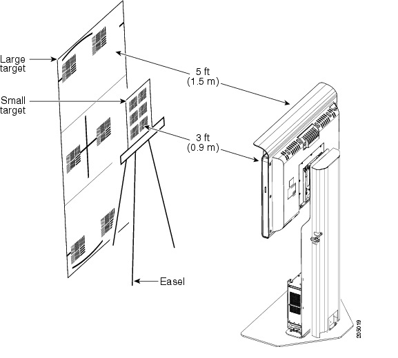
Figure 4-10 Setting Up Focus Targets and Aligning Horizontal Bars
Step 5 ![]() Loosen the thumbscrew on the lens focus ring.
Loosen the thumbscrew on the lens focus ring.
Step 6 ![]() Twist the focus ring clockwise until the red and green horizontal bars on the bottom of the screen are reduced to very short lengths on the left.
Twist the focus ring clockwise until the red and green horizontal bars on the bottom of the screen are reduced to very short lengths on the left.
Step 7 ![]() Twist the focus ring counter-clockwise until the red and green bars extend all the way to the right.
Twist the focus ring counter-clockwise until the red and green bars extend all the way to the right.
Step 8 ![]() Continue to twist the focus ring until the red and green bars are approximately the same length. See Figure 4-10 to view the approximate horizontal bar alignment. When the bars are roughly the same length, the camera is focused.
Continue to twist the focus ring until the red and green bars are approximately the same length. See Figure 4-10 to view the approximate horizontal bar alignment. When the bars are roughly the same length, the camera is focused.
Note ![]() The red and green bars do not have to be exactly the same length. Get them as close as you can.
The red and green bars do not have to be exactly the same length. Get them as close as you can.
Step 9 ![]() Without moving the focus ring, tighten its thumbscrew.
Without moving the focus ring, tighten its thumbscrew.
Step 10 ![]() Click Done.
Click Done.
Step 11 ![]() Click Stop to stop the test.
Click Stop to stop the test.
Saving Your Settings
When you have configured all your settings:
Step 1 ![]() Click Apply to register new or modified settings.
Click Apply to register new or modified settings.
Step 2 ![]() Click Reset to restore the original settings.
Click Reset to restore the original settings.
For more information about testing and troubleshooting the CTS 500 camera, see the Setting Up the Cameras section in the First-Time Setup chapter of the Cisco TelePresence System 500 Assembly, Use & Care, and Field Replaceable Unit Guide.
Reattaching the Camera Haze and Replacing the Hood
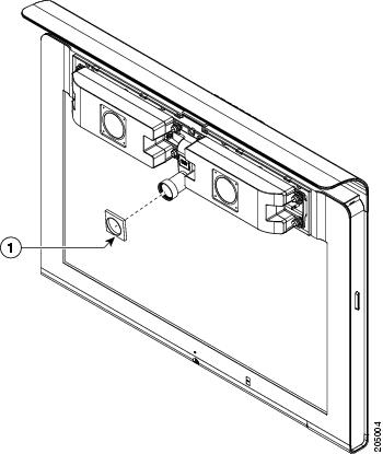
Step 1 ![]() Attach the camera haze cover to the front of the camera lens. The haze cover is the cover with the square edges that goes over the lens as shown in Figure 4-11.
Attach the camera haze cover to the front of the camera lens. The haze cover is the cover with the square edges that goes over the lens as shown in Figure 4-11.
Step 2 ![]() Snap the camera hood back into place.
Snap the camera hood back into place.
Figure 4-11 Attaching Camera Haze Cover Camera Lens
Troubleshooting Cameras
Use the information in Table 4-3 to troubleshoot cameras.
|
|
|
|
|---|---|---|
Image not positioned correctly. |
Camera is not aligned correctly. |
Adjust and focus the camera using the targets. |
Image colors are incorrect. |
• • |
• • |
No image. |
• • |
• • • |
Camera or display is broken. |
Contact Cisco technical support if you are certain that the cabling is correct, power is applied, and a display and camera test has been run, but no image is seen on the display. |
|
Camera top-to-bottom switching discontinuity. |
Image may take up to 1 second to normalize when the camera switches to the active speaker. |
This is normal DSP behavior. Can also occur during audio addin. Contact Cisco technical support. |
Related Information
For more information about setting up and testing cameras, see the Cisco TelePresence System 500 Assembly, Use & Care, and Field Replacement Unit Guide.
For more system troubleshooting information, see the Cisco TelePresence System Troubleshooting Guide on Cisco.com.
Testing Speakers
The speakers are set up successfully when sound can be heard clearly from each one. When running a test, you can choose whether to cycle through the speakers automatically or manually.
Use the information in the following sections to test the speakers for your system:
Testing the Speakers
To test the speakers:
Step 1 ![]() Log in to the Cisco TelePresence System Administration interface.
Log in to the Cisco TelePresence System Administration interface.
Step 2 ![]() Choose Troubleshooting > Hardware Setup
Choose Troubleshooting > Hardware Setup
Step 3 ![]() Click the Speakers radio button.
Click the Speakers radio button.
Step 4 ![]() Click Start to begin the speaker test. The speaker test screen appears, as shown in Figure 4-12
Click Start to begin the speaker test. The speaker test screen appears, as shown in Figure 4-12
Figure 4-12 Speaker Test Screen
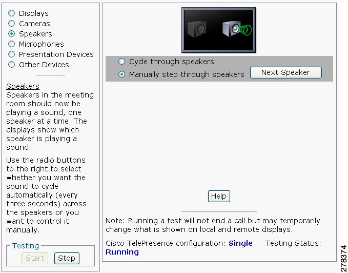
Step 5 ![]() Click Cycle Through Speakers to have sound cycled automatically for 5 seconds on each speaker.
Click Cycle Through Speakers to have sound cycled automatically for 5 seconds on each speaker.
Step 6 ![]() Click Manually Step Through Speakers to test sound on each speaker. The Next Speaker button is activated.
Click Manually Step Through Speakers to test sound on each speaker. The Next Speaker button is activated.
Step 7 ![]() Click Next Speaker to progress to the next speaker.
Click Next Speaker to progress to the next speaker.
Step 8 ![]() Click Stop to end testing.
Click Stop to end testing.
Troubleshooting Speakers
Use the information in Table 4-4 to troubleshoot speakers.
Related Information
For more information about setting up and testing speakers, see the Cisco TelePresence System 500 Assembly, Use & Care, and Field Replacement Unit Guide.
For more system troubleshooting information, see the Cisco TelePresence System Troubleshooting Guide on Cisco.com.
Testing Microphones
The microphones are set up successfully when each microphone registers sound. You must supply sound at each microphone to complete this test.
Note ![]() The number of audio meters that are shown on the test screen is determined by the number of microphones that have been configured in Unified CM and the version of Unified CM that you are running.
The number of audio meters that are shown on the test screen is determined by the number of microphones that have been configured in Unified CM and the version of Unified CM that you are running.
The Microphone Troubleshooting screen displays the number of microphones available for testing:
•![]() CTS 500—1 microphone with a single audio meter displayed on a single test screen.
CTS 500—1 microphone with a single audio meter displayed on a single test screen.
Testing Microphones
Go to the following sections to test microphones:
•![]() Testing Microphones on the CTS 500
Testing Microphones on the CTS 500
Testing Microphones on the CTS 500
To test microphones on the CTS 500:
Step 1 ![]() Log in to the Cisco TelePresence System Administration interface.
Log in to the Cisco TelePresence System Administration interface.
Step 2 ![]() Choose Troubleshooting > Hardware Setup.
Choose Troubleshooting > Hardware Setup.
Step 3 ![]() Click the Microphones radio button.
Click the Microphones radio button.
Step 4 ![]() Click Start in the Testing box to begin the test.
Click Start in the Testing box to begin the test.
Step 5 ![]() Lightly tap each microphone and watch the audio meter on the corresponding display screen to see that sound registers.
Lightly tap each microphone and watch the audio meter on the corresponding display screen to see that sound registers.
Step 6 ![]() Click Stop to end the test.
Click Stop to end the test.
Troubleshooting Microphones
Use the information in Table 4-5 to troubleshoot microphones.

Related Information
For more information about setting up and testing displays, see the Cisco TelePresence System 500 Assembly, Use & Care, and Field Replacement Unit Guide.
For more system troubleshooting information, see the Cisco TelePresence System Troubleshooting Guide on Cisco.com.
Testing Presentation Devices
The output for presentations is handled by alternate displays, projectors, alternate devices, or LCDs. Input one of these devices can be delivered through a Video Graphics Array (VGA) input device (such as a laptop computer) or through a document camera.
Note ![]() You should run this test only if you have presentation display devices installed.
You should run this test only if you have presentation display devices installed.
Table 4-6 contains supported presentation devices listed by system.
|
|
||
|---|---|---|
|
— |
• |
|
|
|
||
|
|
— |
• |
This section contains the following information:
•![]() Checking External Presentation Devices
Checking External Presentation Devices
•![]() Troubleshooting Presentation Devices
Troubleshooting Presentation Devices
Checking External Presentation Devices
The alternate display is set up successfully when the test pattern is displayed on the projection surface in the meeting room while running the test.
Tip ![]() When troubleshooting presentation devices, start with the alternate display test pattern to see if it is set up correctly and then proceed through VGA and document camera input tests as necessary.
When troubleshooting presentation devices, start with the alternate display test pattern to see if it is set up correctly and then proceed through VGA and document camera input tests as necessary.
By default, presentations are displayed as presentation-in-picture (PiP) on the main display screen. You can optionally add an external presentation display screen that displays the presentation instead of displaying it as PiP. This external display is attached to the External Presentation Display HD video connection on the codec. See the Cisco TelePresence System 500 Assembly, Use & Care, and Field-Replaceable Unit Guide for more information.
Note ![]() If the video works for a few minutes and then stops working, your presentation device might use an unsupported video protocol. To see the list of displays that the CTS 500 supports, see the release notes for your CTS software version on Cisco.com.
If the video works for a few minutes and then stops working, your presentation device might use an unsupported video protocol. To see the list of displays that the CTS 500 supports, see the release notes for your CTS software version on Cisco.com.
A PiP softkey will be displayed on the phone only if a PiP is active. Pip is not available for audio-only calls.
Procedure
To test an external presentation device:
Step 1 ![]() Log in to the Cisco TelePresence System Administration interface.
Log in to the Cisco TelePresence System Administration interface.
Step 2 ![]() Choose Troubleshooting > Hardware Setup.
Choose Troubleshooting > Hardware Setup.
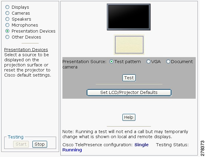
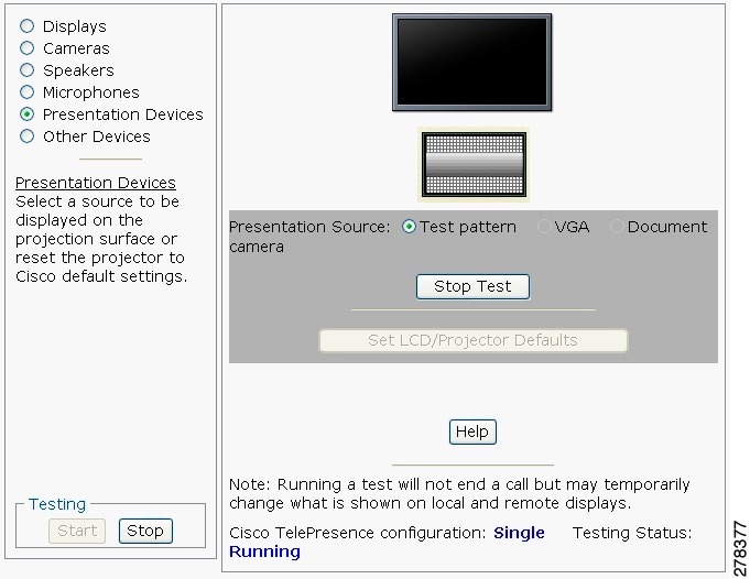
Step 3 ![]() Click Presentation Devices. The presentation devices test screen appears, as shown in Figure 4-13.
Click Presentation Devices. The presentation devices test screen appears, as shown in Figure 4-13.
Figure 4-13 Presentation Devices Test Screen
Proceed to the following sections to test presentation devices:
•![]() Checking the Document Camera.
Checking the Document Camera.
Checking the Test Pattern
To check the test pattern:
Step 1 ![]() Choose Troubleshooting > Hardware Setup.
Choose Troubleshooting > Hardware Setup.
Step 2 ![]() Click Start to begin the test. In Presentation Source window, the Test Pattern radio button is selected by default.
Click Start to begin the test. In Presentation Source window, the Test Pattern radio button is selected by default.
Step 3 ![]() Click Test. The test pattern displays, as shown in Figure 4-14.
Click Test. The test pattern displays, as shown in Figure 4-14.
Figure 4-14 Presentation Devices Test Pattern
It may take up to 15 seconds before you begin to see an image on the projection surface. The image should be fully formed after approximately 45 seconds.
If the test pattern is displaying correctly, you should see a grid projected on the projection surface. In the center of the grid, you should see a series of horizontal grey bars. You should also see a one-pixel wide green border around the outside of the grid.
If the green border is not visible, for systems with an Auxiliary Control Unit, do the following:
a. ![]() Click Set LCD/Projector Defaults. A dialog box opens alerting you that setting projector defaults may take up to 45 seconds. A menu will appear from the projector to select settings.
Click Set LCD/Projector Defaults. A dialog box opens alerting you that setting projector defaults may take up to 45 seconds. A menu will appear from the projector to select settings.
For systems without the Auxiliary Control Unit, use the projector remote control to change the following settings on the projector:
b. ![]() Picture adj: Overscan should be set to 0
Picture adj: Overscan should be set to 0
c. ![]() Screen: Normal
Screen: Normal
Step 4 ![]() Click Stop Test to end the test pattern testing.
Click Stop Test to end the test pattern testing.
Step 5 ![]() Click Set Projector Defaults to reset the projector to the default settings, if necessary.
Click Set Projector Defaults to reset the projector to the default settings, if necessary.
Step 6 ![]() Click Stop in the Testing box to end all testing.
Click Stop in the Testing box to end all testing.
Step 7 ![]() Proceed to Checking the VGA.
Proceed to Checking the VGA.
Checking the VGA
To check the VGA:
Step 1 ![]() Choose Troubleshooting > Hardware Setup.
Choose Troubleshooting > Hardware Setup.
Step 2 ![]() Click the Presentation Devices radio button.
Click the Presentation Devices radio button.
Step 3 ![]() Click Start in the Testing box. The Presentation Source buttons are activated.
Click Start in the Testing box. The Presentation Source buttons are activated.
Step 4 ![]() Select VGA and click Test. It may take up to 15 seconds before you begin to see an image on the projection surface. The image should be fully formed after approximately 45 seconds.
Select VGA and click Test. It may take up to 15 seconds before you begin to see an image on the projection surface. The image should be fully formed after approximately 45 seconds.
If the input image is displaying correctly, you should see an image projected on the projection surface. If the image is out of focus, use the projector focus ring to focus the image.
Step 5 ![]() Click Stop Test to end the test.
Click Stop Test to end the test.
Step 6 ![]() Click Set Projector Defaults to reset the projector to the default settings, if necessary.
Click Set Projector Defaults to reset the projector to the default settings, if necessary.
Step 7 ![]() Click Stop in the Testing box to end all testing.
Click Stop in the Testing box to end all testing.
Checking the Document Camera
To test input from the document camera:
Step 1 ![]() Choose Troubleshooting > Hardware Setup.
Choose Troubleshooting > Hardware Setup.
Step 2 ![]() Click the Presentation Devices radio button.
Click the Presentation Devices radio button.
Step 3 ![]() Click Start in the Testing box. The Presentation Source buttons are activated.
Click Start in the Testing box. The Presentation Source buttons are activated.
Step 4 ![]() Select Document Camera and click Test. It may take up to 15 seconds before you begin to see an image on the projection surface. The image should be fully formed after approximately 45 seconds.
Select Document Camera and click Test. It may take up to 15 seconds before you begin to see an image on the projection surface. The image should be fully formed after approximately 45 seconds.
If the input image is displaying correctly, you should see an image projected on the projection surface. If the image is out of focus, use the projector focus ring to focus the image.
Step 5 ![]() Click Stop Test to end the test.
Click Stop Test to end the test.
Step 6 ![]() Click Set Projector Defaults to reset the projector to the default settings, if necessary.
Click Set Projector Defaults to reset the projector to the default settings, if necessary.
Step 7 ![]() Click Stop in the Testing box to end all testing.
Click Stop in the Testing box to end all testing.
Resetting the Projector
To reset the projector:
Step 1 ![]() Choose Troubleshooting > Hardware Setup.
Choose Troubleshooting > Hardware Setup.
Step 2 ![]() Click the Presentation Devices radio button.
Click the Presentation Devices radio button.
Step 3 ![]() Click Start in the Testing box. The Presentation Source buttons are activated.
Click Start in the Testing box. The Presentation Source buttons are activated.
Step 4 ![]() Click Set Projector Defaults to reset the projector to the default settings.
Click Set Projector Defaults to reset the projector to the default settings.
Step 5 ![]() Click Stop in the Testing box to complete the task.
Click Stop in the Testing box to complete the task.
Troubleshooting Presentation Devices
Use the information in the following sections to troubleshoot presentation devices:
Multiple Input Devices
The Cisco TelePresence System can display information from multiple input devices during a meeting. If multiple input devices are sending information, the alternate display shows the input from the last presentation device that sent information. If an input device image is not being seen on the projector screen, try the following:
•![]() VGA devices—Unplug the device from the VGA cable, wait 5 seconds, and then plug the device back in.
VGA devices—Unplug the device from the VGA cable, wait 5 seconds, and then plug the device back in.
•![]() Document cameras—Turn the camera off, wait 5 seconds, and restart the device.
Document cameras—Turn the camera off, wait 5 seconds, and restart the device.
Presentation Devices
Use the information in Table 4-6 to troubleshoot presentation devices.
|
|
|
|
|---|---|---|
Test pattern is not displayed. |
Projector or alternate display power switch is off. |
• • |
Power cable is not connected. |
• • |
|
Video cable is not connected to the projector, alternate display, or to the CTS primary unit. |
• • |
|
Projector or alternate display is set up to receive PC input instead of input from its video cable connector. |
• • |
|
Object is blocking the path of the projector or alternate display. |
Remove any objects blocking the projector or alternate display lens. |
|
HD Video connector is not securely seated in the projector or alternate display. |
Seat the HD Video connector securely. |
|
HD Video connector is not securely seated in the CTS primary codec. |
Seat the HD Video connector securely. |
|
HD Video connector is not inserted in the correct port on the CTS primary codec. |
The HD Video cable connector should be connected to auxiliary video out. Check the cabling diagrams in the Routing Power and Signal Cables section in the Cisco TelePresence System Assembly, Use & Care, and Field Replacement Unit Guide for your system on Cisco.com: • – – – – • – – – |
|
Caution pop-up: No VGA (DVI) input received. |
• • |
Verify the following: 1. 2. Click OK to close the window. |
Caution pop-up: No input received from document camera. |
Cables are not connected properly. |
Check that all cables are connected and all connectors are plugged in completely. Click OK to close the window. |
System Status window shows unexpected Document Camera status. |
Document camera settings may need to be adjusted in Unified CM. |
Cisco recommends setting the Digital Visual Interface (DVI) resolution to XGA/60 at 1024 x 768/60 Hz. See the Optional Hardware section of the Cisco Unified Communications Manager Configuration Guide for the Cisco TelePresence System for more information. |
There is no image and a Bulb icon appears on the CTS main display.

|
The projector bulb has burned out. |
Replace the projector bulb. |
|
|
||
Related Information
For more information about setting up and testing presentation devices, see the Cisco TelePresence System 500 Assembly, Use & Care, and Field Replacement Unit Guide.
For more system troubleshooting information, see the Cisco TelePresence System Troubleshooting Guide on Cisco.com.
Testing Other Devices
Use the Other Devices Tab to check the following additional devices:
•![]() Troubleshooting Other Devices
Troubleshooting Other Devices
Auxiliary Control Unit
The auxiliary control unit (ACU) controls the individual light units surrounding the displays in CTS conference rooms, which allows the CTS to receive projector or alternate display status information and restore projector or alternate display defaults.
To test the ACU:
Step 1 ![]() Log in to the Cisco TelePresence System Administration interface.
Log in to the Cisco TelePresence System Administration interface.
Step 2 ![]() Choose Troubleshooting > Hardware Setup.
Choose Troubleshooting > Hardware Setup.
Step 3 ![]() Click the Other Devices radio button.
Click the Other Devices radio button.
Step 4 ![]() Click Start in the Testing box. The Auxiliary Control Unit (Current Status) is displayed by default. Individual light units correspond to the five port numbers of the Auxiliary Control Unit, Ports 1 through 5, as shown in Figure 4-15.
Click Start in the Testing box. The Auxiliary Control Unit (Current Status) is displayed by default. Individual light units correspond to the five port numbers of the Auxiliary Control Unit, Ports 1 through 5, as shown in Figure 4-15.
Figure 4-15 CTS 500 ACU Testing
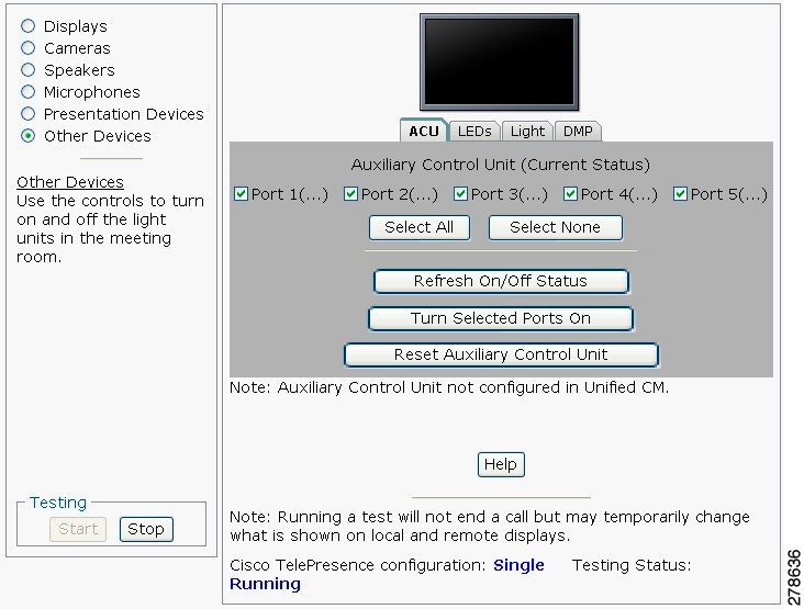
Step 5 ![]() Check a box to select a specific port number.
Check a box to select a specific port number.
Or
Step 6 ![]() Click Select All to select all ports (and all light units) or Select None.
Click Select All to select all ports (and all light units) or Select None.
Step 7 ![]() Click the Refresh On/Off Status button to update the on/off status of each port.
Click the Refresh On/Off Status button to update the on/off status of each port.
Step 8 ![]() Click the Turn Selected Ports On button.
Click the Turn Selected Ports On button.
Step 9 ![]() Click the Reset Auxiliary Control Unit to power cycle the Auxiliary Control Unit.
Click the Reset Auxiliary Control Unit to power cycle the Auxiliary Control Unit.
Step 10 ![]() Click Stop to end the test.
Click Stop to end the test.
Auxiliary LCD Displays
Each CTS 500 has five LEDs located around the outside edges of the screen. If the user can see these LEDs, the user is not sitting directly in front of the camera. This troubleshooting feature lets you view and change the current state of the LEDs.
To test the LEDs:
Step 1 ![]() Log in to the Cisco TelePresence System Administration interface.
Log in to the Cisco TelePresence System Administration interface.
Step 2 ![]() Choose Troubleshooting > Hardware Setup.
Choose Troubleshooting > Hardware Setup.
Step 3 ![]() Click the Other Devices radio button.
Click the Other Devices radio button.
Step 4 ![]() Select the LEDs tab.
Select the LEDs tab.
Step 5 ![]() Click Start in the Testing box. The LED status is displayed, as shown in Figure 4-16.
Click Start in the Testing box. The LED status is displayed, as shown in Figure 4-16.
Figure 4-16 CTS 500 LED Status
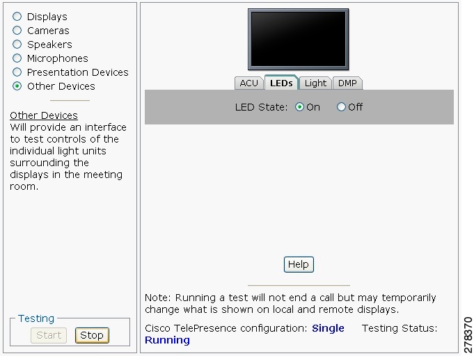
•![]() If the LED feature is enabled, the LED State On button is highlighted.
If the LED feature is enabled, the LED State On button is highlighted.
•![]() If the LED feature is disabled, the LED State Off button is highlighted.
If the LED feature is disabled, the LED State Off button is highlighted.
Step 6 ![]() Click the LED State On or Off button to change the current state of the LEDs.
Click the LED State On or Off button to change the current state of the LEDs.
Step 7 ![]() Click Stop to end the test.
Click Stop to end the test.
Shroud Light
Each CTS 500 has a separate shroud light. This troubleshooting feature lets you view or change the status of the shroud light.
To test the shroud light:
Step 1 ![]() Log in to the Cisco TelePresence System Administration interface.
Log in to the Cisco TelePresence System Administration interface.
Step 2 ![]() Choose Troubleshooting > Hardware Setup.
Choose Troubleshooting > Hardware Setup.
Step 3 ![]() Click the Other Devices radio button.
Click the Other Devices radio button.
Step 4 ![]() Select the Light tab.
Select the Light tab.
Step 5 ![]() Click Start in the Testing box. The CTS 500 light status is displayed, as shown in Figure 4-17.
Click Start in the Testing box. The CTS 500 light status is displayed, as shown in Figure 4-17.
Figure 4-17 CTS 500 Light Status
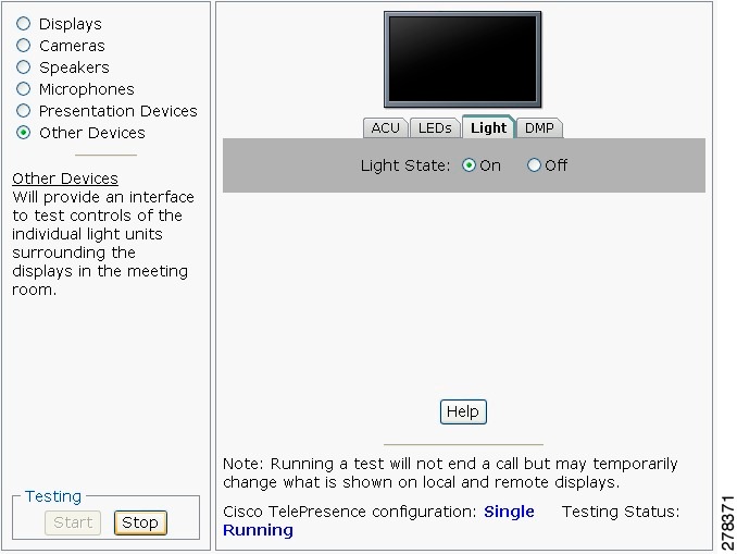
•![]() If the shroud light feature is enabled, the Light State On button will be highlighted.
If the shroud light feature is enabled, the Light State On button will be highlighted.
•![]() If the shroud light feature is disabled, the Light State Off button will be highlighted.
If the shroud light feature is disabled, the Light State Off button will be highlighted.
Step 6 ![]() Click the Light State On or Light State Off button to change the current state of the shroud light.
Click the Light State On or Light State Off button to change the current state of the shroud light.
Step 7 ![]() Click Stop to end the test. The state of the light reverts to its default setting as it was configured in the Unified CM.
Click Stop to end the test. The state of the light reverts to its default setting as it was configured in the Unified CM.
Digital Media Player
The Digital Media Player (DMP) feature lets you select a secondary audio input source when you are not in a TelePresence call.
For more information about the DMP, see the Cisco Digital Media Players home page on Cisco.com.
To test the DMP:
Step 1 ![]() Log in to the Cisco TelePresence System Administration interface.
Log in to the Cisco TelePresence System Administration interface.
Step 2 ![]() Choose Troubleshooting > Hardware Setup.
Choose Troubleshooting > Hardware Setup.
Step 3 ![]() Select the DMP tab.
Select the DMP tab.
Step 4 ![]() Click Start in the Testing box to begin testing the secondary audio input. The DMP status is displayed, as shown in Figure 4-18.
Click Start in the Testing box to begin testing the secondary audio input. The DMP status is displayed, as shown in Figure 4-18.
Figure 4-18 CTS 500 DMP Status
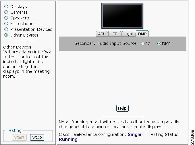
•![]() If you have a PC attached, the Secondary Audio Input Source PC button is highlighted. When Secondary Audio Input Source is set to PC, the audio input is active while the presentation source is active, both in and out of a call.
If you have a PC attached, the Secondary Audio Input Source PC button is highlighted. When Secondary Audio Input Source is set to PC, the audio input is active while the presentation source is active, both in and out of a call.
•![]() If you have a DMP attached, the Secondary Audio Input Source DMP button is highlighted. When set to DMP, audio input is only active outside of a call if DMP is active (during business hours defined by Unified CM).
If you have a DMP attached, the Secondary Audio Input Source DMP button is highlighted. When set to DMP, audio input is only active outside of a call if DMP is active (during business hours defined by Unified CM).
Note ![]() The DMP settings should match how the secondary auxiliary audio input is physically connected to the codec.
The DMP settings should match how the secondary auxiliary audio input is physically connected to the codec.
Step 5 ![]() Click Stop to end the test.
Click Stop to end the test.
Troubleshooting Other Devices
Use the information in Table 4-8 to troubleshoot Other Devices.
|
|
|
|
|---|---|---|
|
DMP audio is playing during a call. |
The Secondary Audio Input Source setting may be wrong. |
• • |
Local presentation audio is not playing during a call. |
The Secondary Audio Input Source setting may be wrong. |
• • |
Presentation fails to display in some resume scenarios. |
This is expected behavior. |
In early CTS software releases, a CTS with its presentation device plugged in would always ask to present when it did a resume. Presentation device functionality is changed. When a CTS goes on hold, the presentation device takes note whether or not it was the active presenter: • • |
Administration login can be slow when presenting during point-to-point secure calls. |
This is expected behavior. |
Administration CLI login can take as much as 60 seconds during point-to-point secure calls when a hold/resume is performed while presenting. |
CTS 500 shroud light does not function properly. |
The Auxiliary Control Unit option is not checked in the Optional Hardware Devices box of the Cisco Unified Communications Manager configuration interface. |
The Auxiliary Control Unit check-box must be selected for the lights to function. See the Optional Hardware section of the Cisco Unified Communications Manager Configuration Guide for the Cisco TelePresence System for more information. |
|
|
||
Related Information
For more information about setting up and testing other devices, see the Cisco TelePresence System 500 Assembly, Use & Care, and Field Replacement Unit Guide.
For more system troubleshooting information, see the Cisco TelePresence System Troubleshooting Guide on Cisco.com.
Managing Log Files
Tip ![]() If you are using Internet Explorer, remember to turn off Pop-up Blocker or configure Pop-up Blocker to allow the IP address before capturing system log files.
If you are using Internet Explorer, remember to turn off Pop-up Blocker or configure Pop-up Blocker to allow the IP address before capturing system log files.
Use Log Files to view system operation (sysop) log files, Session Initiation Protocol (SIP) messages and log files from the Cisco TelePresence system. Click the appropriate tab at the top of the window to view the following information:
Sysop Log
To manage System Operation (Sysop) Log messages:
Step 1 ![]() Choose Troubleshooting > Log Files.
Choose Troubleshooting > Log Files.
Step 2 ![]() Select the Sysop Files tab to view system operation messages, including call information, call statistics, and call errors for the Cisco TelePresence system. There can be up to 20 individual files saved on the CTS, and each file can contain up to 100,000 characters.
Select the Sysop Files tab to view system operation messages, including call information, call statistics, and call errors for the Cisco TelePresence system. There can be up to 20 individual files saved on the CTS, and each file can contain up to 100,000 characters.
Step 3 ![]() Click the Download Sysop Files button at the bottom of the page to download the sysop log files. CTS Administration software then prompts you to do one of the following:
Click the Download Sysop Files button at the bottom of the page to download the sysop log files. CTS Administration software then prompts you to do one of the following:
a. ![]() Open to view the sysop log files—The last 100,000 bytes of the log are shown. When you download Sysop Files, all available Sysop files will be downloaded.
Open to view the sysop log files—The last 100,000 bytes of the log are shown. When you download Sysop Files, all available Sysop files will be downloaded.
Or
b. ![]() Save the sysop log files.
Save the sysop log files.
Log Files
Use Log Files to retrieve log files from the Cisco TelePresence system. Log files can be retrieved from the CTS or from the phone.
To manage log files:
Step 1 ![]() Choose Troubleshooting > Log Files.
Choose Troubleshooting > Log Files.
Step 2 ![]() Select the Log Files tab. The following fields are displayed:
Select the Log Files tab. The following fields are displayed:
•![]() Log Status—Shows the status of the log capture, including the percentage completed.
Log Status—Shows the status of the log capture, including the percentage completed.
•![]() Time Generated—Shows the time of the most recent log file capture.
Time Generated—Shows the time of the most recent log file capture.
•![]() Problem Type—Drop-down menu contains the following:
Problem Type—Drop-down menu contains the following:
–![]() Audio (speakers, microphones)
Audio (speakers, microphones)
–![]() Video (displays, cameras)
Video (displays, cameras)
–![]() Projector (or alternate display), LCD, document camera
Projector (or alternate display), LCD, document camera
–![]() Phone
Phone
–![]() Recording
Recording
–![]() Other/Unknown
Other/Unknown
Figure 4-19 shows the problem types that you can select when downloading log files.
Figure 4-19 Select Problem Type Drop-Down Menu

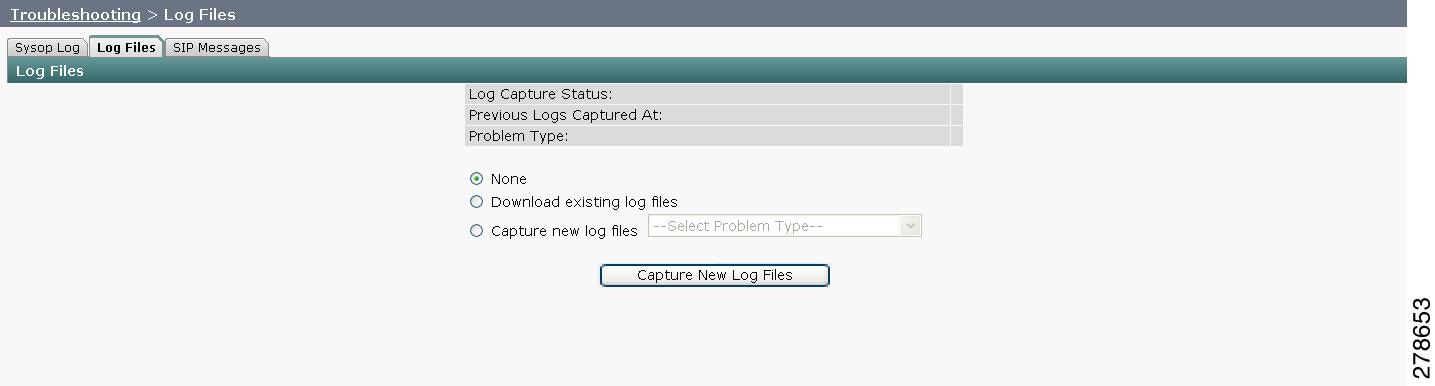
Step 3 ![]() Choose from one of the following options:
Choose from one of the following options:
•![]() None —Default. No log files will be captured unless a download option is selected. Figure 4-20 shows the log download radio button options.
None —Default. No log files will be captured unless a download option is selected. Figure 4-20 shows the log download radio button options.
•![]() Download existing log files—You must select this radio button to download logs.
Download existing log files—You must select this radio button to download logs.
•![]() Capture New Log Files—The system will capture but not download the log files.
Capture New Log Files—The system will capture but not download the log files.
Note ![]() You must disable Internet Explorer Pop-up Blocker to capture new log files with the Capture New Log Fils button.
You must disable Internet Explorer Pop-up Blocker to capture new log files with the Capture New Log Fils button.
Figure 4-20 Downloading Log Files
Step 4 ![]() Select the "Download existing log files" radio button and then select a problem from the Select Problem Type drop-down menu:
Select the "Download existing log files" radio button and then select a problem from the Select Problem Type drop-down menu:
–![]() Audio (speakers, microphones)
Audio (speakers, microphones)
–![]() Video (displays, cameras)
Video (displays, cameras)
–![]() Projector, alternate display, LCD, document camera
Projector, alternate display, LCD, document camera
–![]() Phone
Phone
–![]() Recording
Recording
–![]() Other/Unknown
Other/Unknown
Step 5 ![]() Click the Download Existing Log Files button. The following message appears:
Click the Download Existing Log Files button. The following message appears:
"A WinZip download will start within several minutes.
Please wait..."
The File Download window appears prompting you to open or save the file. Click Save to send the gzip file to Cisco technicians to help solve the problem.
Or
Step 6 ![]() Select the "Capture new log files" radio button and then click the Capture New Log Files button. The following message appears:
Select the "Capture new log files" radio button and then click the Capture New Log Files button. The following message appears:
"Collecting Cisco TelePresence system log files. This may take several minutes.
Please wait..."
The File Download window appears prompting you to open or save the file. Click Save to send the gzip file to Cisco technicians to help solve the problem.
SIP Messages
Use SIP Messages to view the current Session Initiation Protocol (SIP) messages log file. SIP request and response methods are used to establish communications between components in the network and ultimately to establish a call or session between two or more endpoints. Table 4-9 and Table 4-10 describe the SIP requests and message types.
To manage SIP messages:
Step 1 ![]() Choose Troubleshooting > Log Files.
Choose Troubleshooting > Log Files.
Step 2 ![]() Select the SIP Messages tab. The SIP Messages window appears.
Select the SIP Messages tab. The SIP Messages window appears.
Step 3 ![]() View a specific type of message in the SIP log file by doing the following:
View a specific type of message in the SIP log file by doing the following:
a. ![]() Enter the filter where the SIP Message Type is by typing the name in the field provided. The Filter button is activated.
Enter the filter where the SIP Message Type is by typing the name in the field provided. The Filter button is activated.
Or
b. ![]() Select the message type from the drop-down menu. The Filter button is activated.
Select the message type from the drop-down menu. The Filter button is activated.
c. ![]() Click the Filter button to view the SIP messages of the type you specified.
Click the Filter button to view the SIP messages of the type you specified.
Step 4 ![]() Choose the number of messages to view at one time from the Rows Per Page drop-down menu. You can use the First, Previous, Next, and Last buttons to navigate through the message list with the Navigating Long Lists option. You can also Generate Detailed Message Reports.
Choose the number of messages to view at one time from the Rows Per Page drop-down menu. You can use the First, Previous, Next, and Last buttons to navigate through the message list with the Navigating Long Lists option. You can also Generate Detailed Message Reports.
Generate Detailed Message Reports
To see additional details associated with a SIP message:
Step 1 ![]() Double-click on a SIP message from the list to open the SIP Message Details dialog box. The SIP Message Details dialog box opens containing the message details and Related SIP Messages.
Double-click on a SIP message from the list to open the SIP Message Details dialog box. The SIP Message Details dialog box opens containing the message details and Related SIP Messages.
Or
Step 2 ![]() Highlight the SIP message and click the Details button. The SIP Message Details dialog box opens containing the message details and Related SIP Messages.
Highlight the SIP message and click the Details button. The SIP Message Details dialog box opens containing the message details and Related SIP Messages.
Related SIP Messages
The bottom portion of the SIP Message Details window lists SIP messages that are related to the SIP message that was selected at the top of the window.
To view related SIP message details:
Step 1 ![]() Double-click a message in the Related SIP Messages window to see details for that message. SIP Requests and Methods and SIP Response Categories are explained below.
Double-click a message in the Related SIP Messages window to see details for that message. SIP Requests and Methods and SIP Response Categories are explained below.
Step 2 ![]() Click Close to dismiss this window.
Click Close to dismiss this window.
Use the information in the following sections to initiate SIP requests and responses:
SIP Requests and Methods
Table 4-9 summarizes the SIP requests and methods supported by the Cisco TelePresence System Administration software. The first column lists the RFC that describes the SIP request messages or method.
|
|
|
|
|---|---|---|
3261 |
ACK |
Confirms that the client has received a final response to an INVITE request. |
3261 |
BYE |
Terminates a call. Can be sent by either the caller or the called party. |
3261 |
CANCEL |
Cancels any pending searches but does not terminate any call currently in progress. |
2976 |
INFO |
Allows session-related control information generated during a session to be carried along the SIP signaling path. |
3261 |
INVITE |
Indicates that a user or service is being invited to participate in a call session. |
3265 |
NOTIFY |
Immediately upon successful accepting or refreshing of a subscription, a NOTIFY message is sent to communicate the current resource state to the subscriber. This NOTIFY message is sent in the same dialog as that created by the SUBSCRIBE message. |
3261 |
OPTIONS |
Queries the capabilities of servers. |
3262 |
PRACK |
Provides reliability for 1xx type messages; see Table 4-9. |
3515 |
REFER |
Provides a mechanism allowing the party sending the REFER message to be notified of the outcome of the referenced request. |
3261 |
REGISTER |
Registers the address listed in the To header field with a SIP server. |
3265 |
SUBSCRIBE |
Requests current state and state updates from a remote node. |
3311 |
UPDATE |
Allows a client to update parameters of a session, but has no impact on the state of a dialog. This request can be sent before the initial INVITE has been completed, thereby making it useful for updating session parameters within early dialogs. |
SIP Response Categories
SIP replies to the requests in Table 4-9 using the response categories described in Table 4-10.
Navigating Long Lists
The log file can hold up to 2 MB worth of SIP messages. To navigate long lists:
Step 1 ![]() Choose the number of rows that you wish to see on one page from the Rows Per Page drop-down menu.
Choose the number of rows that you wish to see on one page from the Rows Per Page drop-down menu.
Step 2 ![]() Double click to select and open single message details. The SIP Message Details window appears.
Double click to select and open single message details. The SIP Message Details window appears.
Step 3 ![]() If there are multiple pages listing log files, click the First, Previous, Next, or Last button to navigate to the desired page.
If there are multiple pages listing log files, click the First, Previous, Next, or Last button to navigate to the desired page.
Step 4 ![]() Click the radio button to the left of the table entry, and then click Clear to delete a single error message.
Click the radio button to the left of the table entry, and then click Clear to delete a single error message.
Step 5 ![]() Click Clear All to delete all error messages displayed.
Click Clear All to delete all error messages displayed.
Related Information
For more information, see the following documentation:
•![]() Session Initiation Protocol (SIP) home page on Cisco.com.
Session Initiation Protocol (SIP) home page on Cisco.com.
•![]() Cisco TelePresence System Message Guide
Cisco TelePresence System Message Guide
Testing Audio
You can test the system audio in your meeting room and send the results to Cisco Systems technical support for analysis.
Note ![]() Audio recordings can be made only while the CTS system is in a call.
Audio recordings can be made only while the CTS system is in a call.
To record audio:
Step 1 ![]() Choose Troubleshooting > Audio.
Choose Troubleshooting > Audio.
Step 2 ![]() Click Start Recording Audio to start recording all audio in the local meeting room including audio from remote meeting rooms. Recording will continue up to a maximum of two minutes unless you manually stop recording.
Click Start Recording Audio to start recording all audio in the local meeting room including audio from remote meeting rooms. Recording will continue up to a maximum of two minutes unless you manually stop recording.
Note ![]() Both endpoints will beep periodically during the recording process and when audio add-in participants join the call.
Both endpoints will beep periodically during the recording process and when audio add-in participants join the call.
Step 3 ![]() Click Stop Audio Recording to stop recording.
Click Stop Audio Recording to stop recording.
Step 4 ![]() After you complete the recording and download the results, send the results to Cisco Systems technical support.
After you complete the recording and download the results, send the results to Cisco Systems technical support.
Related Information
For more system troubleshooting information, see the Cisco TelePresence System Troubleshooting Guide on Cisco.com.
Testing the Network Connection
Use the Network Connection window to view and modify the duplex and automatic negotiation settings for the Cisco TelePresence system Ethernet connection. Auto negotiation is set to Off by default.
You can change the following network connection settings:
•![]() Auto Negotiation on
Auto Negotiation on
•![]() Auto Negotiation off
Auto Negotiation off
To manage Auto Negotiation:
Step 1 ![]() Choose Troubleshooting > Network Connection.
Choose Troubleshooting > Network Connection.
Step 2 ![]() Click the On or Off radio button to enable or disable auto negotiation. The Apply and Reset buttons are activated, as shown in Figure 4-21.
Click the On or Off radio button to enable or disable auto negotiation. The Apply and Reset buttons are activated, as shown in Figure 4-21.
Figure 4-21 Auto Negotiate On
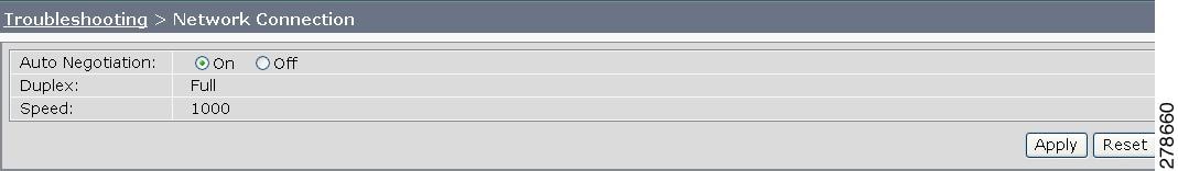
Note ![]() When Auto Negotiation is enabled, the Duplex and Speed settings are read-only.
When Auto Negotiation is enabled, the Duplex and Speed settings are read-only.
Step 3 ![]() Click Apply to save your settings or click Reset to restore the original settings.
Click Apply to save your settings or click Reset to restore the original settings.
Related Information
For more system troubleshooting information, see the Cisco TelePresence System Troubleshooting Guide on Cisco.com.
Managing Configuration Issues
Use the Configuration Issues window to view hardware and software versions and to reset the system to use the factory default software image and the default configuration.
To view hardware and software versions and active images, choose Troubleshooting > Configuration Issues. The Hardware/Software Versions page appears listing the current hardware and software versions and active images.
Resetting the System

Resetting the system can take over two hours to complete.
A system reset results in the following:
•![]() The CTS is reset to the software image as originally shipped.
The CTS is reset to the software image as originally shipped.
•![]() All configuration settings are reset to the factory defaults.
All configuration settings are reset to the factory defaults.
If you select to reset the system to use factory defaults, check the Cisco IP telephone for messages during the reset procedure:
•![]() Data in bold blue text indicates where the current system image is located for each codec in the system.
Data in bold blue text indicates where the current system image is located for each codec in the system.
•![]() Locations of the factory image are listed.
Locations of the factory image are listed.
To reset the system image to the factory default:
Step 1 ![]() Choose Troubleshooting > Configuration Issues. The Hardware/Software Versions page appears listing the current hardware and software versions and active images.
Choose Troubleshooting > Configuration Issues. The Hardware/Software Versions page appears listing the current hardware and software versions and active images.
Step 2 ![]() Click the Reset to Factory Image and Factory Configuration...and Restart Cisco TelePresence System... button. The system image location is changed and the is system restarted.
Click the Reset to Factory Image and Factory Configuration...and Restart Cisco TelePresence System... button. The system image location is changed and the is system restarted.
Note ![]() If a Cisco TelePresence call is in progress, the changes will be made after the call ends.
If a Cisco TelePresence call is in progress, the changes will be made after the call ends.
Related Information
For more system troubleshooting information, see the Cisco TelePresence System Troubleshooting Guide on Cisco.com.
Initiating System Restart
To restart the system:
Step 1 ![]() Choose Troubleshooting > System Restart. The System Restart page appears and the current call status is displayed.
Choose Troubleshooting > System Restart. The System Restart page appears and the current call status is displayed.
Step 2 ![]() Click the Restart Cisco TelePresence System button. The system immediately restarts.
Click the Restart Cisco TelePresence System button. The system immediately restarts.
Troubleshooting Video Quality Settings
Use the information in Table 4-11 to troubleshoot the video picture on the displays.
|
|
|
|
|---|---|---|
Video picture is good but experiences repeated interruptions. |
Video quality setting is set too high. |
1. 2. Note |
Note |
||
Troubleshooting Network Cabling
For all Cisco TelePresence systems, the Cisco Unified IP phone is connected to the primary codec using an Ethernet cable (RJ-45 connector). An RJ-45 connector is also required for the following additional network connections:
•![]() An Ethernet cable (RJ-45) connects the primary codec to the user network.
An Ethernet cable (RJ-45) connects the primary codec to the user network.
For detailed cabling information, see the Routing Power and Signal Cables section in the Cisco TelePresence System Assembly, Use & Care, and Field Replacement Unit Guide for your system on Cisco.com:
•![]() Product Support > TelePresence > TelePresence Immersive Endpoints
Product Support > TelePresence > TelePresence Immersive Endpoints
–![]() Cisco TelePresence System 3200 Series
Cisco TelePresence System 3200 Series
–![]() Cisco TelePresence System 3000 Series
Cisco TelePresence System 3000 Series
–![]() Cisco TelePresence System 1300 Series
Cisco TelePresence System 1300 Series
–![]() Cisco TelePresence System T Series
Cisco TelePresence System T Series
•![]() Products > TelePresence > TelePresence Personal Endpoints > TelePresence Office
Products > TelePresence > TelePresence Personal Endpoints > TelePresence Office
–![]() Cisco TelePresence System 1100
Cisco TelePresence System 1100
–![]() Cisco TelePresence System 1000
Cisco TelePresence System 1000
–![]() Cisco TelePresence System 500 Series
Cisco TelePresence System 500 Series
Table 4-12 contains problem scenarios and troubleshooting solutions for network cabling.
|
|
|
|
|---|---|---|
Cisco Unified IP Phone is off. |
• • • • |
• • • |
Cisco IP Phone does not register with the IP network. |
• • |
• |
Cisco IP Phone does not register with the IP network. |
• • |
• • • |
Cisco Telepresence phone idle screen does not appear. |
Device configuration has not been done or has been done incorrectly. |
• • |
Note |
||
CTS 500 32" Troubleshooting
Because the CTS 500 32" uses a first-time setup wizard, configuring and troubleshooting tasks are somewhat different than other CTS models. Refer to Troubleshooting the CTS 500-32 and CTS 500-37 in this guide and to the following support documentation on Cisco.com:
•![]() Cisco TelePresence System 500 32" Assembly, Use & Care, and Field-Replaceable Unit Guide
Cisco TelePresence System 500 32" Assembly, Use & Care, and Field-Replaceable Unit Guide
Where to Go Next
See the Chapter 12 "Monitoring the Cisco TelePresence System."
For information about system messages that may appear on the Cisco TelePresence system, see the Cisco TelePresence System Message Guide on the Cisco TelePresence Administration Software Error and System Messages home page on Cisco.com.
 Feedback