Get To Know Your Switch

This chapter contains the following sections:

Introduction

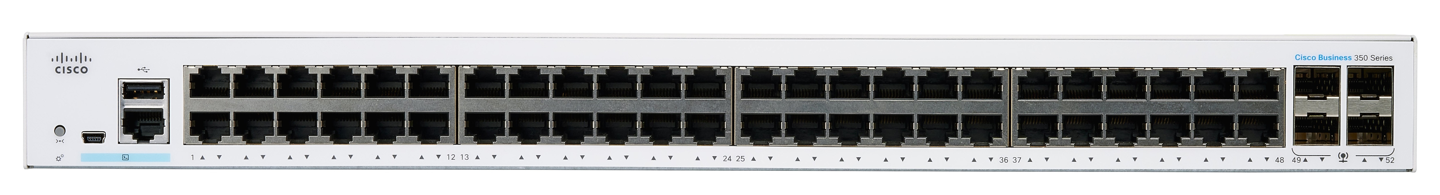
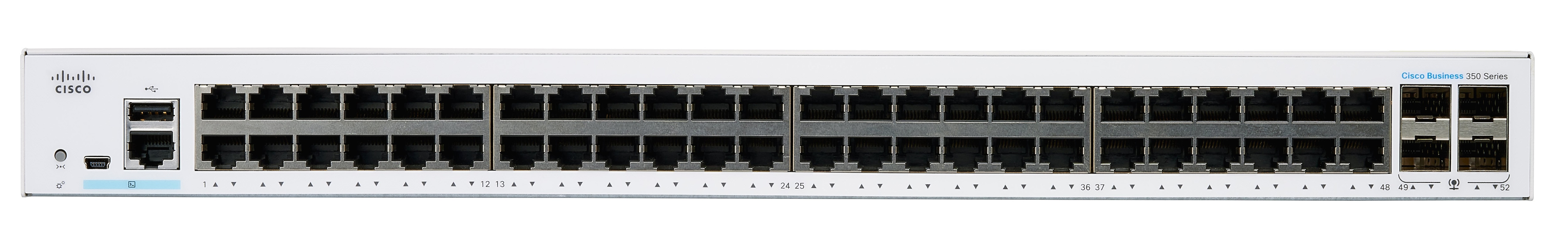
Thank you for purchasing the Cisco CBS Series Switch. The Cisco CBS Series Switches combine powerful network performance and reliability with a complete suite of network features that you need for a solid business network. These expandable Gigabit Ethernet switches, with Gigabit or 10-Gigabit uplinks, provide multiple management options, rich security capabilities, and Layer-3 static routing features far beyond those of an unmanaged or consumer-grade switch, at a lower cost than fully managed switches.

Before You Begin

Before you begin installing your device, ensure that the following items are available:

  • RJ-45 Ethernet cables for connecting network devices. A category 6a and higher cable is required for 10G ports; a category 5e and higher cable is required for all other ports.

  • Tools for installing the hardware.

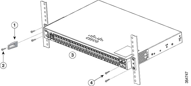
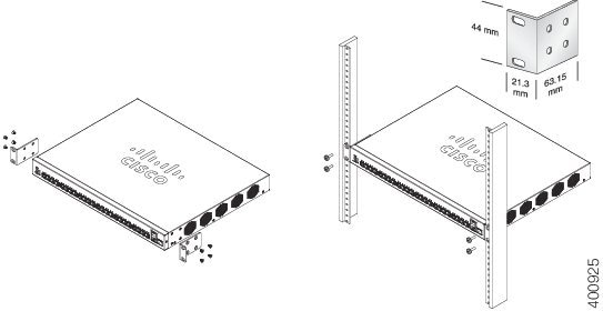
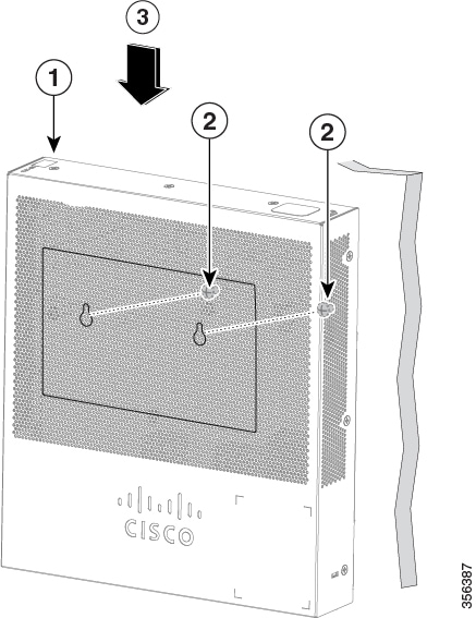
    • The rack-mount kit packed with the switch contains four rubber feet for desktop placement, and two brackets and twelve screws for rack mounting.

    • If the supplied screws are lost, use replacement screws in the following size:

      • Diameter of the screw head: 6.9 mm

      • Length of the face of the screw head to the base of screw: 5.9 mm

      • Shaft diameter: 3.94 mm


    Warning


    To prevent airflow restriction, allow clearance around the ventilation openings to be at least 3 inches (7.6 cm).


  • A computer to manage the device either via the console port or via the web-based interface. for web-based interface the computer needs to support one of the following browsers:

    • Microsoft Edge

    • Firefox (version 82 or 81 or higher)

    • Chrome (version 86 or 85 or higher)

    • Safari over MAC (version 14.0 and higher)


Warning


Suitable for installation in information Technology Rooms in accordance with Article 645 of the national Electric Code and NFPA 75.


Rack Mounting Switch

You can mount the switches on any standard size, 19-inch (about 48 cm) wide rack. The switch requires 1 rack unit (RU) of space, which is 1.75 inches (44.45 mm) high.


Caution


For stability, load the rack from the bottom to the top, with the heaviest devices on the bottom. A top-heavy rack is likely to be unstable and might tip over.


To install the switch into a 19-inch standard chassis:

Procedure


Step 1

Place one of the supplied brackets on the side of the switch so that the four holes of the brackets align to the screw holes, and then use the four supplied screws to secure it.

Step 2

Repeat the previous step to attach the other bracket to the opposite side of the switch.

Step 3

After the brackets are securely attached, the switch is now ready to be installed into a standard 19-inch rack.


Note


Use supplied brackets to rack mount the switch.


Supplied rack mounting for switch models with front mounting position. The mounting ears do not sit flush to the front panel.

Due to design differences, some of the mounting brackets will attach such that the switch will protrude about an inch from the mounting surface.

Supplied rack mounting for switch models with front mounting position. The mounting ears sit flush to the front panel.

Wall Mounting a Switch

You can mount the switches on a wall, using wall studs or to a firmly attached plywood mounting backboard.


Caution


Read these instructions carefully before beginning installation. Failure to use the correct hardware or to follow the correct procedures could result in a hazardous situation to people and damage to the system.


Caution


Do not wall-mount the switch with its front panel facing up. Following safety regulations, wall mount the switch with its front panel facing down or to the side to prevent airflow restriction and to provide easier access to the cables.


To wall-mount a 24-port switch using brackets:

Procedure


Step 1

Attach a 19-inch bracket to one side of the switch.

Step 2

Repeat the previous step to attach the other bracket to the opposite side of the switch.

Step 3

After the brackets are securely attached, mount the switch with the front panel facing down. Make sure that the switch is attached securely to wall studs or to a firmly attached plywood-mounting backboard. Wall-mounting a 24-port switch.

Wall-mounting a 24-port


Wall Mount an 8 Port Switch

To wall-mount a 8-port switch using mounting screws, follow these steps:

Procedure


Step 1

Locate the screw template. The template is used to align the mounting screw holes.

Step 2

Position the screw template so that the edge that is marked as CABLE SIDE ENTRY faces toward the floor. Make sure that the switch is attached securely to wall studs or to a firmly attached plywood mounting backboard.

Step 3

Peel the adhesive strip off the bottom of the screw template.

Step 4

Attach the screw template to the wall.

Step 5

Use a 0.144-inch (3.7 mm) or a #27 drill bit to drill a 1/2-inch (12.7 mm) hole in the two screw template slots.

Step 6

Insert two screws in the slots on the screw template and tighten them until they touch the top of the screw template. Installing the mounting screws on the wall

Figure 3 Installing the mounting screws on the wall

Step 7

Remove the screw template from the wall.

Step 8

Place the switch onto the mounting screws, and slide it down until it locks in place. Wall-mounting an 8-port switch

Figure 4 Wall-mounting an 8-port switch


Out-Of-Band Port

The CBS350 “10G network port SKUs” support an Out-of-Band (OOB) port which can be used for the management network. The out-of-band and the in-band ports share the same IP routing table. Thus, the same subnet cannot be used on both the in-band and out-of-band interfaces.

The OOB port is assigned a MAC address which differs from the base MAC address and the in-band ports addresses. This MAC address is used as the source MAC address in all frames sent by the switch on the OOB port.

By default, VLAN 1 is configured with a default IP address 192.168.1.254, and can be accessed through any in-band interfaces. This default IP address is used when no other address is assigned (dynamically or statically). There is no default IP address on OOB port.

Table 1. VLAN 1 and OOB Factory Default IP settings – Old and new behavior

Cisco Business firmware up to version 3.1

Cisco Business firmware version 3.1.1

OOB interface

VLAN 1 interface

OOB interface

VLAN 1 interface

IP settings

Default IP + DHCP

DHCP enable

Default IP + DHCP

Interface CLI configuration

None

None

"IP address DHCP"

None

Other

Bonjour enabled

None

None

Bonjour enabled

Stacking the Switches

A stack can have multiple devices in it. Any 10G port of the switch can be used for stacking.

By default, the ports on the switch function as regular Ethernet ports, except if you configure them to do stacking. You cannot mix the stack speeds between the switches or ports.

At least two ports must be chosen for stacking in a given switch" and those ports must be 10Gig speed. For two switches or more to form a stack, they must be running the same version of the firmware. This is the more reason SG series switches cannot be stacked with CBS series switches. CBS250 series switches do not have stacking capabilities.

Some switches have their stack LEDs numbered 1, 2, 3, and 4 to indicate Active, Standby, and Member while the others types use the system LED flashing behavior to describe the same thing.


Note


Stack ports must have the same speed capability on the module or cable plug in.


The switch can only be stacked without Mesh topology. The switches in the same stack are connected together through their stack ports. Depending on the type of stack ports and the desired speed, you may need Cat6a Ethernet cables or Cisco approved modules or cables for the switches.

Some network switches have the ability to be connected to other switches and operate together as a single unit. These configurations are called stacks, and they are useful for quickly increasing the capacity of your network.

Stack Management

The Cisco Business switches have a couple of different stacking modes, and you can stack different models.

Also, you need to note what feature may or may not be available in different stacking modes (native or hybrid).

  • Native Stacking- The switch is part of a stack in which all of the units are of the same type.

  • Hybrid Stacking – The switch is part of a stack that can consist of either mixed type of CBS350 devices.

Cisco Business Switch Stacking Mode Selector

This tool will guide you to selecting the correct stacking settings for your 10G Cisco Business 350 series switch. Click on the link below to access the tool.

https://www.cisco.com/c/en/us/support/docs/smb/switches/Cisco-Business-Switching/kmgmt-2799-switch-stack-selector-cbs.html


Note


You cannot stack the legacy switches with the new Cisco Business stackable switches. If you are stacking the legacy switches, consult the following link: https://www.cisco.com/c/en/us/support/docs/smb/switches/cisco-350x-series-stackable-managed-switches/smb5367-feature-support-comparison-between-the-cisco-stackable-manag.html


Feature Support on Hybrid Mode

The feature set of the CBS350 SKUs with 10G network ports and the feature CBS350 SKUs with 10G uplink ports are nearly identical. However, there are a few differences in feature support and table sizes between the 2 “sub-types”. The Cisco Business switches hybrid stack mode will support the lower denominator for these features/tables The following table lists the feature differences between the 2 sub-types and the setting applied in hybrid mode:

Hybrid mode works in any combination of stacking albeit reduced performance, MAC table size for example can be reduced; but switches of the same model number (same PID) can take advantage of native stacking mode. Some switches with different PID can stack in native mode as well, other combinations, however, can only stack in hybrid mode.

In general, except for the CBS350-48XT-4X, all CBS350 switches that support stacking and have designated uplink ports in their PID can stack natively among themselves, and those that do not have uplink ports, including the CBS350-48T-4X can stack, among themselves, in native mode as well. The hybrid mode staking comes into play only when mixing these two blocks, uplink supporting devices and non-uplink supporting devices. So. knowing the exact PID of a given switch is so crucial when it comes to stacking mode determination. The CBS350-48T-4X, although has 4X at the end of the PID that should designate this as supporting an uplink, it is not the case, this 4X designation in this switch does not indicate uplink, instead, they are network port (downlink port) as are the other ports in the switch.

Changing stacking mode from Native to Hybrid will force a switch to reboot and most of its settings in its startup configuration will reset to default; on the other hand, changing the stacking mode from Hybrid to Native will force the unit to reboot, but the settings will not reset back to default.

Feature

CBS350 “10G uplink port SKUs”

CBS350 “10G network port SKUs”

Hybrid stack

OOB port

Not Supported

Supported

Not Supported

Green Settings (Short reach and Energy Detect)

Per SKU and port type behavior

Per SKU and port type behavior

Per SKU and port type behavior

MAC table size

16K

32K or 64K

16K

Number of Multicast groups

2K

4K

2K

Number of ACEs supported

1K- reserved

2K- reserved

1K- reserved

Total number of IP entries

992

7392

992

ARP table size

1K – reserved

8K – reserved

1K – reserved

Max number of IPv6 interfaces

106

200

106

Max MAC table aging

400 seconds

630 seconds

400 seconds

IPv6 Manual Tunnel/ 6tp4 tunnel/ ISATAP routing tunnel

Not supported

Supported

Not supported

PoE support

Supported on specific SKUs

Not supported

Per SKU type

Default number of VLAN Mapping entries

0

32

0

Default IP address

On VLAN 1

On VLAN 1

On VLAN 1

Power over Ethernet Considerations

Some switches support PoE while others do not. The switch models that support PoE have a P in their model number, such as: CBSxxx-xxP-xx. If your switch is one of the Power over Ethernet (PoE) models, consider the following power requirement.

Warning


The switch is to be connected only to PoE networks without routing to the outside plant.


Table 2. Switches with Power Over Ethernet

SKU Name

Description

PoE PD Chipset Type

PoE PSE Support

CBS350-8MGP-2X

8-Port 2.5G PoE Managed Switch

1*69208M

AF/AT

CBS350-8MP-2X

8-Port 2.5G PoE Stackable Managed Switch

1*69208M

AF/AT

CBS350-24MGP-4X

24-Port 2.5G PoE Stackable Managed Switch

1*69208M + 1*69204

AF/AT/60W

CBS350-12NP-4X

12-Port 5G PoE Stackable Managed Switch

3 * TPS2388

AF/AT/60W

CBS350-24NGP-4X

24-Port 5G PoE Stackable Managed Switch

4* TPS2388

AF/AT/60W

CBS350-48NGP-4X

48-Port 5G PoE Stackable Managed Switch

7* TPS2388

AF/AT

/60W

CBS350-8P-2G

8-Port Gigabit PoE Managed Switch

TPS2388

AF/AT

CBS350-8P-E-2G

8-Port Gigabit PoE Managed Switch

TPS2388

AF/AT

CBS350-8FP-2G

8-Port Gigabit PoE Managed Switch

TPS2388

AF/AT

CBS350-8FP-E-2G

8-Port Gigabit PoE Managed Switch

TPS2388

AF/AT

CBS350-16P-2G

16-Port Gigabit PoE Managed Switch

2*TPS2388

AF/AT

CBS350-16P-E-2G

16-Port Gigabit PoE Managed Switch

2*TPS2388

AF/AT

CBS350-16FP-2G

16-Port Gigabit PoE Managed Switch

2*TPS2388

AF/AT

CBS350-24P-4G

24-Port Gigabit PoE Managed Switch

3*TPS2388

AF/AT

CBS350-24FP-4G

24-Port Gigabit PoE Managed Switch

3*TPS2388

AF/AT

CBS350-48P-4G

24-Port Gigabit PoE Managed Switch

6*TPS2388

AF/AT

CBS350-48FP-4G

48-Port Gigabit PoE Managed Switch

6*TPS2388

AF/AT

CBS350-24P-4X

24-Port Gigabit PoE Stackable Managed Switch with 10G Uplinks

3*TPS2388

AF/AT

CBS350-24P-4X

24-Port Gigabit PoE Stackable Managed Switch with 10G Uplinks

3*TPS2388

AF/AT

CBS350-24FP-4X

48-Port Gigabit PoE Stackable Managed Switch with 10G Uplinks

6*TPS2388

AF/AT

CBS350-48P-4X

48-Port Gigabit PoE Stackable Managed Switch with 10G Uplinks

6*TPS2388

AF/AT

CBS350-48FP-4X

48-Port Gigabit PoE Stackable Managed Switch with 10G Uplinks

6*TPS2388

AF/AT


Caution


Consider the following when connecting a PoE switch. 
The PoE switches are PSE (Power Sourcing Equipment) that are capable of supplying DC power to attaching powered devices (PD). These devices include VoIP phones, IP cameras, and wireless access points. The PoE switches can detect and supply power to pre-standard legacy PoE PD. Due to the PoE legacy support, it is possible that a PoE switch acting as a PSE may mistakenly detect and supply power to an attaching PSE, including other PoE switches, as a legacy PD. 
Even though PoE switches are PSE, and as such should be powered by AC, they could be powered up as a legacy PD by another PSE due to false detection. When this happens, the PoE switch may not operate properly and may not be able to properly supply power to its attaching PDs. 


To prevent false detection, you should disable PoE on the ports on the PoE switches that are used to connect to PSEs. You should also first power up a PSE device before connecting it to a PoE switch. When a device is being falsely detected as a PD, you should disconnect the device from the PoE port and power recycle the device with AC power before reconnecting its PoE ports.


Front Panel

The ports, LEDs, and Reset button are located on the front panel of the switch, as well as the following components:

Cisco Business 350 Series Model


Note


Models may differ within the CBS 350 series and this is just a representation of a model within the series.


  • There are 2 device types with different console interface:

    • Console port with RJ-45 and mini USB connector if both are connected the Mini USB has precedence over the RJ-45

    • RJ-45 connector only type of console.

    The console interface connects a serial cable to a computer serial port so that it can be configured using a terminal emulation program or mini USB cable (depending on the connector).

  • USB Port—The USB port connects the switch to a USB device so that you can save and restore the configuration files, firmware images, and SYSLOG files through the connected USB device. The USB port supports the FAT32 file system.

  • RJ-45 Ethernet Ports—The RJ-45 Ethernet ports connect network devices, such as computers, printers, and access points, to the switch.

  • SFP+ Port (if present)—The small form-factor pluggable plus (SFP+) are connection points for modules so that the switch can link to other switches. These ports are also commonly referred to as mini 10GigaBit Interface Converter ports. The term SFP+ is used in this guide.

    • The SFP+ ports (if present) are compatible with the following Cisco SFP 1G optical modules MGBSX1, MGBLX1, MGBLH1, MGBT1, as well as other brands.

    • The SFP+ ports are compatible with the following Cisco SFP 1G optical modules MGBSX1, MGBLX1, MGBLH1, MGBT1, as well as other brands.

    • The Cisco SFP+ Copper Cable modules that are supported in the Cisco switches are: SFP-H10GB-CU1M, SFP-H10GB-CU3M, and SFP-H10GB-CU5M.

    • The LEDs of the corresponding RJ-45 port flash green to respond to the SFP interface traffic.

  • Small form-factor pluggable (SFP) ports are connection points for modules, so the switch can link to other switches.

  • Some SFP interfaces are shared with one other RJ-45 and SFP+ port, called a combo port. When the SFP is active, the adjacent RJ-45 port is disabled.

  • Reset button is used to reset or reboot the switch. The table below displays the reset behavior on the switch.

    Press Type

    New Behavior (Firmware 3.2 and on)

    Old Behavior (Firmware prior to 3.2)

    1- 5 seconds

    System LED is green, releasing button does not cause reload.

    Reload

    6- 10 seconds

    System LED flash green, releasing button during this period will cause device reload, but system is not set to factory default.

    Reload

    11-15 seconds

    System LED is green, releasing button does not cause reload

    Factory default

    16-20 seconds

    System LED flashes green, releasing button during this period will cause device reload to factory default

    Factory default

    > 20 seconds

    System LED is green, releasing button does not cause reload

    Factory default


    Note


    Stack Behavior

    The reset button disable setting is applied to all units in the stack, meaning that if configured, the reset button on all units in the stack are disabled, and if not configured the reset button on all units in the stack are enabled. This applies also to units that join an existing stack.


  • OOB Port (if present)—The Out of Band (OOB) port is a CPU Ethernet port that can be used only as a management interface. Bridging between the OOB port and the in-band Layer 2 interface is not supported. This does not appear on 250 devices.

  • Multi-Gigabit Ethernet Ports (if present) —Highlighted in blue, these ports support speeds up to 2.5 Gbps or 5 Gbps on Cat5e cables. The maximum speed supported is printed on the blue shade under the port. Uplink ports on CBS350-8MGP-2X also support multi-Gigabit speed. In this case, port speed can reach 10Gbps. Most of the cabling deployed worldwide is Cat5e, and previously limited to 1 Gbps at 100 meters. Cisco multi-Gigabit Ethernet enables speeds up to 2.5 or 5 Gbps on the same infrastructure without replacing a cable.

  • 60-Watt PoE Ports (if present)- The 60-Watt PoE port doubles the maximum PoE power delivered on the port to 60W.

Front Panel LEDs

The following are the global LEDs found on the devices:

  • System—(Green) The LED lights steady when the switch is powered on, and flashes when booting, performing self-tests, or acquiring an IP address. If the LED flashes Amber, the switch has detected a hardware or firmware failure, and/or a configuration file error.

The following LEDs describe the stacking status of the unit.

  • *Stack ID LED (Green)- The LED lights steady when the switch is stacked and the corresponding number indicates its Stack ID.

  • *Active Unit ID LED- indicating this is the stack active unit.


    Note


    * These two LEDs are only available on certain models.


  • System LED- Every 20 seconds, the System LED will flash according to unit ID of the member unit.

    • Flash = LED going off and then on again.

    • According to unit ID of the unit. This means

      • Unit 1 (if not active unit)- system LED will flash 1 time

      • Unit 2 (if not active unit)- system LED will flash 2 times

      • Unit 3- system LED will flash 3 times

      • Unit 4-system LED will flash 4 times;

    • The duration of each flash (LED off time) will be as follows:

      • LED off time (in each flash) ~ 0.5 seconds.

      • “Interim” LED on (between 2 LED offs) ~ 0.5 seconds

    • If a member unit is removed from the stack, its system LED will continue to flash according to above definition.

The following are per port LEDs:

  • LINK/ACT—(Green) Located on the left of each port. The LED lights steady when a link between the corresponding port and another device is detected, and flashes when the port is passing traffic.

  • SFP+ (if present)—(Green) Located on the right of a 10G port. The LED lights steady when a connection is made through the shared port, and flashes when the port is passing traffic.

  • XG—(Green) Located on the right of a 10G port. The LED lights steady when another device is connected to the port, is powered on, and a 10 Gbps link is established between the devices. When the LED is off, the connection speed is under 10 Gbps or nothing is cabled to the port.

  • Gigabit—(Green) Located on the right of the 1G port. The LED lights steady when another device is connected to the port, is powered on, and a 1000 Mbps link is established between the devices. When the LED is off, the connection speed is under 1000 Mbps or nothing is cabled to the port. (This feature is only available on certain models).

  • PoE (if present)—(Amber) Located on the right of the port. The LED lights steady when power is being supplied to a device attached to the corresponding port. (This feature is only available on certain models).

Configuring Switches

The switch can be accessed and managed over your IP network using the web-based interface, or by using the switch’s command-line interface through the console port. Using the console port requires advanced user skills and is only supported on certain models.

The following table shows the default settings used when configuring your switch for the first time.

Parameter

Default Value

Username

cisco

Password

cisco

LAN IP

192.168.1.254

Configuring Your Switch Using the Web-based Interface

To access the switch with a web-based interface, you must know the IP address that the switch is using. The switch uses the factory default IP address of 192.168.1.254, with a subnet of /24. When the switch is using the factory default IP address, the System LED flashes continuously. When the switch is using a DHCP server-assigned IP address or an administrator has configured a static IP address, the System LED is a steady green (DHCP is enabled by default).

If you are managing the switch through a network connection and the switch IP address is changed, either by a DHCP server or manually, your access to the switch will be lost. You must enter the new IP address that the switch is using into your browser to use the web-based interface. If you are managing the switch through a console port connection, the link is retained.

To configure the switch using the web-based interface:

Procedure


Step 1

Power on the computer and your switch.

Step 2

Connect the computer to any network port.

Step 3

Set up the IP configuration on your computer.

  1. If the switch is using the default static IP address of 192.168.1.254/24, you must choose an IP address for the computer in the range of 192.168.1.2 to 192.168.1.253 that is not already in use.

  2. If the IP addresses will be assigned by DHCP, make sure that your DHCP server is running and can be reached from the switch and the computer. You may need to disconnect and reconnect the devices for them to discover their new IP addresses from the DHCP server.

    Note


    Details on how to change the IP address on your computer depend upon the type of architecture and operating system that you are using. Use your computers local Help and Support functionality and search for “IP Addressing.”

Step 4

Open a web browser window.

Step 5

Enter the switch IP address in the address bar and press Enter. For example,
http://192.168.1.254.

Step 6

When the login page appears, choose the language that you prefer to use in the web-based interface and enter the username and password.

The default username is cisco. The default password is cisco. Usernames and passwords are both case sensitive.

Step 7

Click Log In.

Step 8

If this is the first time that you have logged on with the default username and password, the Change username and Password. Enter a new username and password and confirm.

If this is the first time that you have logged on with the default username and password, the Change username and Password

page opens

Note

 
Please refer to the password complexity rule section in Login Settings before creating a password.

Step 9

Click Apply.

Caution


Make sure that any configuration changes made are saved before exiting from the web-based interface by clicking on the Save icon. Exiting before you save your configuration results in all changes being lost.

The Getting Started page opens. You are now ready to configure the switch. Refer to the Administration Guide or see the help pages for further information.


Configuring Your Switch Using the Console Port

To configure the switch using the console port, which is only supported on certain models, proceed with the following steps:

Procedure


Step 1

Connect a computer to the switch console port using a Cisco console cable (purchased separately) or a cable with mini USB connector.

Step 2

Start a console port utility such as Hyper Terminal on the computer.

Step 3

Configure the utility with the following parameters:

  • 115200 bits per second

  • 8 data bits

  • no parity

  • 1 stop bit

  • no flow control

Step 4

Enter a username and password. The default username is cisco, and the default password is cisco. Usernames and passwords are both case sensitive.

If this is the first time that you have logged on with the default username and password, the following message appears:

Please change your username AND password from the default settings. Change of credentials is required for better protection of your network.
Please note that new password must follow password complexity rules

Step 5

Set a new administrator username and password.

Caution


Make sure that any configuration changes made are saved before exiting.

You are now ready to configure the switch. See the CLI Guide for your switch.

Note


If you are not using DHCP on your network, set the IP address type on the switch to Static and change the static IP address and subnet mask to match your network topology. Failure to do so may result in multiple switches using the same factory default IP address of 192.168.1.254.

Console access also provides additional interfaces for debug access which are not available via the web interface. These debug access interfaces are intended to be used by a Cisco Support Team personnel, in cases where it is required to debug device’s behavior. These interfaces are password protected. The passwords are held by the Cisco support team. The device supports the following debug access interfaces:

  • U-BOOT access during boot sequence

  • Linux Kernel access during boot sequence

  • Run time debug modes- allows Cisco support team to view device settings and apply protocol and layer 1 debug commands and settings. The run time debug mode is accessible over telnet and SSH terminals in addition to the console.


Navigation

The navigation menu, located at the top right of each UI page, lists the device’s main features. You can access each feature’s UI pages using a series of cascading menus. To access an individual UI page, click the corresponding feature tab in the navigation menu to display a menu of subcategories. Select a subcategory and repeat this process until you see the desired page, and then select the page to display it in the main window.

Basic or Advanced Display Mode

The product supports many features, and therefore the WEB GUI includes hundreds of configuration and display pages. These pages are divided into the following display modes:

  • Basic—Basic subset of configuration options are available. If you are missing some configuration option, select the Advanced mode in the device header.

  • Advanced—Full set of configuration options are available.

When the user switches from basic to advanced, the browser reloads the page. However, after reloading, the user stays on the same page. When the user switches from advanced to basic, the browser reloads the page. If the page exists also on the basic mode, the user stays on the same page. If the page does not exist in the basic mode, the browser will load the first page of the folder which was used by the user. If the folder does not exist, the Getting Started page will be displayed.

If there is an advanced configuration, and the page is loaded in basic mode, a page-level message will be displayed to the user (e.g, there are 2 radius servers configured but in basic mode only a single server can be displayed, or there is 802.1X port authentication with time range configured but time range is not visible in basic mode). When switching from one mode to another, any configuration which was made on the page (without Apply) is deleted.