G.8032 Ethernet Ring Protection

Overview of G.8032 Ethernet Ring Protection

The G.8032 Ethernet Ring Protection feature implements protection switching mechanisms for Ethernet layer ring topologies. This feature uses the G.8032 Ethernet Ring Protection (ERP) protocol version 1, defined in ITU-T G.8032, to provide protection for Ethernet traffic in a ring topology with non-Cisco devices.

ITU-T G.8032 Ethernet Ring Protection Switching Functionality

The Ethernet ring protection functionality includes the following:

  • Loop avoidance

  • The use of learning, forwarding, and Filtering Database (FDB) mechanisms

Loop avoidance in an Ethernet ring is achieved by ensuring traffic flows continuously through all links except the Ring Protection Link (RPL).

Here is a list of RPL types (or RPL nodes) and their functions:

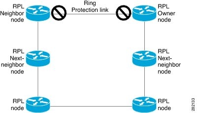
  • RPL owner—Responsible for blocking traffic over the RPL to prevent loops in the Ethernet traffic. There can be only one RPL owner in a ring.

  • RPL neighbor node—An Ethernet ring node adjacent to the RPL. It is responsible for blocking its end of the RPL under normal conditions. This node type is optional and prevents RPL usage when protected.

  • RPL next-neighbor node—Next-neighbor node is an Ethernet ring node adjacent to an RPL owner node or RPL neighbor node. It is mainly used for FDB flush optimization on the ring. This node is also optional.

The figure illustrates the G.8032 Ethernet ring topology.

Figure 1. G.8032 Ethernet Ring Topology

R-APS Control Messages

Nodes on the ring use control messages called Ring Automatic Protection Switching (R-APS) messages to coordinate switching the ring protection link (RPL) on and off. A failure along the ring triggers a R-APS Signal Failure (R-APS SF) message in both directions of the nodes adjacent to the failed link after they have blocked the port facing the failed link. Upon receipt of this message, the RPL owner unblocks the RPL port.


Note


A single link failure in the ring ensures a loop-free topology.


G.8032 ERP Timers

The G.8032 Ethernet Ring Protection (ERP) protocol specifies the use of different timers to avoid race conditions and unnecessary switching operations:

  • Delay timers—Used by the Ring Protection Link (RPL) owner to verify that the network has stabilized before blocking the RPL. Note the following points about delay timers.

    • After a signal failure (SF) condition, a Wait-to-Restore (WTR) timer is used to verify that the SF is not intermittent.

    • The WTR timer can be configured by the operator. The default time interval is 5 minutes; the time interval ranges from 1 to 12 minutes.

    • After a force switch (FS) or a manual switch (MS) command is issued, a Wait-to-Block (WTB) timer is used to verify that no background condition exists.


      Note


      The WTB timer interval may be shorter than the WTR timer interval.


  • Guard timer—Used by all nodes when changing state; the guard timer blocks latent outdated messages from causing unnecessary state changes. The guard timer can be configured. The default time interval is 500 ms; the time interval ranges from 10 to 2000 ms.

  • Hold-off timers—Used by the underlying Ethernet layer to filter out intermittent link faults. The hold-off timer can be configured. The default time interval is 0 seconds; the time interval ranges from 0 to 10 seconds. Faults are reported to the ring protection mechanism only if this timer expires.

Benefits

  • Provides sub-50 millisecond protection and recovery for Ethernet traffic.

  • Supports up to 32 nodes per ring, ensuring scalability in network design.

  • Supports up to 128 VLANs and 1024 MAC addresses.

  • Supports both copper and fiber ports for versatile deployment.

  • Enables multicast traffic support within the ring topology.

  • Ensures rapid fault detection through the CFM protocol, enhancing network reliability.

Supported Scenarios

The G.8032 Ethernet Ring Protection feature is ideal for networks that require rapid recovery and high availability, such as service provider networks, large enterprises, and data centers with Ethernet ring topologies. It is especially useful in scenarios where minimal downtime is critical.

Prerequisites

  • Each node must be configured with a single ring.

  • The CFM protocol must be operational for fault management.

Restrictions

  • This feature is supported only on Cisco IE31xx series switches and third-party switches with G.8032 compatibility.

  • The feature operates independently and cannot be combined with other ring protocols.

    It should not be enabled on ports configured with STP, DLR, REP, or MRP protocols. Furthermore, no other ring configurations should be retained, even in a dormant state.

    On ports not configured for G.8032, STP and other protocols are expected to function normally.

  • Only one ring per instance is supported. Multiple ring configurations are not supported

  • G.8032 ring ports should be configured in VLAN trunk mode.

  • G.8032 ring ports cannot be configured on port-channel interfaces.

  • Sub-50 milliseconds convergence is not supported at an interface speed of 100 Mbps. However, it is supported for 1Gigabit Ethernet interfaces.

  • The control VLAN should be exclusively used for G.8032 ERPS and CFM control packets and should not be used for any other user or control traffic.

  • G.8032 convergence is only supported with a CFM (CCM) interval of 3.3 ms. Other CCM intervals are not supported.

  • The G8032 ring node role as a next-neighbor is not supported in the current release.

Configuration Workflow

Follow these steps to configure the G.8032 ring:

  1. Create a G.8032 ring profile

  2. Keep the interfaces shut before bringing them under the G.8032 ring configuration

  3. Configure the G.8032 ring

  4. Configure the ports under the G.8032 ring configuration

  5. Configure the profile, VLAN inclusion list, and other instance-related configuration

    The instance command remains unchanged to align with other Cisco product configurations and to prevent future CLI changes when multiple ring instances are supported.

  6. Configure the CFM domain to level 1, and enable EFD notification

  7. Configure the ring ports with VLAN and CFM configurations, then run the no shutdown command

Configure the Ethernet Ring Profile

The G.8032 Ethernet Ring profile specifies the operational and configuration parameters for particular network requirements. You can use the default profile or create a custom one by following the procedure provided here.

Procedure


Step 1

Use the ethernet ring g8032 profile profile-name command to create the Ethernet ring profile and enter Ethernet ring profile configuration mode.

Example:

Device(config)# ethernet ring g8032 profile g8032-profile

Step 2

(Optional) Use the timer wtr minutes command to set the duration for the Wait-to-Restore (WTR) timer.

Example:

Device(config-erp-profile)# timer wtr 1

The valid range is from 1 to 12, with a default of 5 minutes.

Step 3

(Optional) Use the timer guard interval command to set the duration for the guard timer.

Example:

Device(config-erp-profile)# timer guard 600

The valid range is from 10 to 2000, with a default of 500 milliseconds.

Step 4

(Optional) Use the timer hold-off seconds command to set the duration for the hold-off timer.

Example:

Device(config-erp-profile)# timer hold-off 4

The valid range is from 0 to 10, with a default of 0 seconds.

Step 5

(Optional) Use the no non-revertive command to configure a nonrevertive Ethernet ring instance.

Example:

Device(config-erp-profile)# no non-revertive

By default, revertive mode is enabled.


Configure the Ethernet Protection Ring

The Ethernet Protection Ring (EPR) ensures reliable and efficient operation of Ethernet networks in ring topologies. Follow the procedure given here to configure EPR.

Procedure


Step 1

Use the ethernet ring g8032 ring-name command to specify the Ethernet ring and enter Ethernet ring port configuration mode.

Example:

Device(config)# ethernet ring g8032 g8032_ring

Step 2

Use the port0 interface type number command to connect port0 of the local node to the Ethernet ring and enter Ethernet ring protection mode.

Example:

Device(config-erp-ring)# port0 interface GigabitEthernet1/3

Step 3

Use the exit command to enter the Ethernet ring port configuration mode.

Example:

Device(config-erp-ring-port)# exit

Step 4

Use the port1 interface type number command to connect port1 of the local node of the interface to the Ethernet ring and enter the Ethernet ring protection mode.

Example:

Device(config-erp-ring)# port1 interface GigabitEthernet1/4

Step 5

Use the exit command to enter the Ethernet ring port configuration mode.

Example:

Device(config-erp-ring-port)# exit

Step 6

Use the instance instance-id command to assign the Ethernet service instance to monitor the ring port (port0) and detect ring failures.

Example:

Device(config-erp-ring)# instance 1

Step 7

(Optional) Use the profile profile-name command to specify the Ethernet ring profile.

Example:

Device(config-erp-inst)# profile g8032-profile

The default profile is automatically applied, if no profile is specified.

Step 8

Use the rpl {port0 | port1}{owner | neighbor } command to specify the Ethernet ring port on the local node as the RPL owner or neighbor.

Example:

Device(config-erp-inst)# rpl port0 owner

Specify the RPL port connected to both the owner and neighbor nodes. These nodes must be adjacent and directly connected by a single link.

RPL port configuration is required for both the owner and neighbor nodes, while it is not needed for a normal node. By default, each node is considered a normal node.

Step 9

Use the inclusion-list vlan-ids vlan-id command to specify the VLANs that are managed (traffic management) by the Ethernet ring protection mechanism.

Example:

Device(config-erp-inst)# inclusion-list vlan-ids 10, 100-200

For vlan-id , use a list or individual VLAN IDs in the format a-b or c, where a-b denotes a range and c represents a single VLAN ID.

Step 10

Use the aps-channel command to enter Ethernet ring instance aps-channel configuration mode.

Example:

Device(config-erp-inst)# aps-channel

The APS channel allows control and coordination messages to flow between nodes or devices to ensure the protection mechanism operates correctly and efficiently.

Step 11

(Optional) Use the level level-value command to specify the APS message level for the node on the Ethernet ring.

Example:

Device(config-erp-inst-aps)# level 1

The APS message level ranges from 0 (lowest) to 7 (highest).

Step 12

Use the control vlan vlan-id command to define a control VLAN dedicated to carrying APS messages within the network.

Example:

Device(config-erp-inst-aps)# control vlan 10

The control VLAN should not be used for any other purpose.

The valid vlan-id range is 1 to 4094.


Enable Ethernet Fault Detection for a Service

This procedure helps a service achieve fast convergence, which is crucial for ensuring network services are reliable, resilient, and high-performing.


Note


Ethernet Connectivity and Fault Management (CFM) includes a broad range of messages and protocols. For G.8032 sub-50ms convergence, this platform supports only 3.3ms CCM messages at Maintenance Domain Level 1.


Procedure


Step 1

Use the ethernet cfm ieee command to enable IEEE-compliant Ethernet CFM on a device.

Example:

Device(config)# ethernet cfm ieee

Step 2

Use the ethernet cfm global command to globally enable Ethernet CFM.

Example:

Device(config)# ethernet cfm global

Step 3

Use the ethernet cfm domain domain-name level level command to configure the CFM domain and enter Ethernet CFM configuration mode.

Example:

Device(config)# ethernet cfm domain g8032_domain level 1 

The domain-name is the name of the maintenance domain.

The level defines the fault management level within the maintenance domain. We support only level 1.

Step 4

Use one of the three methods listed here to configure service.

  • Use the service vlan-id vlan-id vlan vlan-id direction down command to define a VLAN-id based maintenance association and enter Ethernet CFM service instance configuration mode.
    Device(config-ecfm)# service vlan-id 10 vlan 10 direction down 
  • Use the service name vlan vlan-id direction down command to define a service name based maintenance association and enter Ethernet CFM service instance configuration mode.
    Device(config-ecfm)# service G8032_Service vlan 10 direction down 
  • Use the service number number vlan vlan-id direction down command to define a service number based maintenance association and enter Ethernet CFM service instance configuration mode.
    Device(config-ecfm)# service number 12 vlan 10 direction down 

    The valid vlan-id range is from 1 to 4094.

Step 5

Use the continuity-check command to enable the transmission of 3.3ms continuity check messages.

Example:

Device(config-ecfm-srv)# continuity-check 

Step 6

Use the efd notify g8032 command to enable CFM to notify registered protocols when a defect is detected or cleared, which matches the current fault alarm priority.

Example:

Device(config-ecfm-srv)# efd notify g8032 

This command is essential for achieving sub-50ms convergence.


Configure Interface

Interfaces are required to configure the specific ports used in the Ethernet ring. Follow the procedure given here to configure an interface.

Procedure


Step 1

Use the interface gigabitethernet type number command to specify the interface type and number.

Example:

Device(config)# interface gigabitethernet 1/3

Step 2

Use the switchport trunk allowed vlan vlan-list command to specify the VLANs that are allowed to traverse when this port is in trunking mode.

Example:

Device(config-if)# switchport trunk allowed vlan 10,100-200 

The vlan-list denotes the range of VLAN-IDs. It should include the VLANs in the inclusion list.

Note


The control VLAN and inclusion VLAN list should match this configuration.

Step 3

Use the switchport mode trunk command to specify a port on the switch to operate in trunk mode, which allows it to carry traffic from multiple VLANs..

Example:

Device(config-if)# switchport mode trunk

Step 4

Use the ethernet cfm mep domain domain-name mpid mpid service vlan-id vlan-id command to set a port as internal to a maintenance domain and define it as a Maintenance End Point (MEP).

Example:

Device(config-if)# ethernet cfm mep domain g8032_domain mpid 12 service number 10

This example in the procedure is based on service number. You can use also VLAN-id and service name.

The domain-name specifies the maintenance domain to which the MEP belongs.

Note that the MPID must be unique on peer devices. No two Maintenance Points within a single service can share the same MPID. Valid values range from 1-8191.

The vlan-id represents the specific VLAN that the MEP will be monitoring within the domain. Valid values range from 1-4094.

Ideally, the control VLAN should also be used for configuring the service VLAN.


Verify G.8032 Ethernet Ring Protection

Use the show commands given here to verify the configuration and status of G.8032 Ethernet Ring Protection.

show ethernet ring g8032 status

The show ethernet ring g8032 status [ring-name][instance [instance-id]] command displays the status information of an Ethernet Ring configured using the G.8032 standard.


Device# show ethernet ring g8032 status

Ethernet ring g8032_ring instance 1 is RPL Owner node in Idle State
 Port0: GigabitEthernet1/3
  APS-Channel: GigabitEthernet1/3
  Status: RPL, blocked
  Remote R-APS NodeId: 0000.0000.0000, BPR: 0
 Port1: GigabitEthernet1/4
  APS-Channel: GigabitEthernet1/4
  Status: Non-RPL
  Remote R-APS NodeId: 0000.0000.0000, BPR: 0
 APS Level: 7
 Profile: g8032_profile
  WTR interval: 1 minutes
  Guard interval: 10 milliseconds
  HoldOffTimer: 0 seconds
  Revertive mode

Device# show ethernet ring g8032 status g8032_ring

Ethernet ring g8032_ring instance 1 is RPL Owner node in Idle State
 Port0: GigabitEthernet1/3
  APS-Channel: GigabitEthernet1/3
  Status: RPL, blocked
  Remote R-APS NodeId: 0000.0000.0000, BPR: 0
 Port1: GigabitEthernet1/4
  APS-Channel: GigabitEthernet1/4
  Status: Non-RPL
  Remote R-APS NodeId: 0000.0000.0000, BPR: 0
 APS Level: 7
 Profile: g8032_profile
  WTR interval: 1 minutes
  Guard interval: 10 milliseconds
  HoldOffTimer: 0 seconds
  Revertive mode

Device# show ethernet ring g8032 status g8032_ring instance 1

Ethernet ring g8032_ring instance 1 is RPL Owner node in Idle State
 Port0: GigabitEthernet1/3
  APS-Channel: GigabitEthernet1/3
  Status: RPL, blocked
  Remote R-APS NodeId: 0000.0000.0000, BPR: 0
 Port1: GigabitEthernet1/4
  APS-Channel: GigabitEthernet1/4
  Status: Non-RPL
  Remote R-APS NodeId: 0000.0000.0000, BPR: 0
 APS Level: 7
 Profile: g8032_profile
  WTR interval: 1 minutes
  Guard interval: 10 milliseconds
  HoldOffTimer: 0 seconds
  Revertive mode

show ethernet ring g8032 summary

This command displays a summary of the G.8032 Ethernet Ring, providing a high-level overview of its operational state, status, and key metrics.


Device# show ethernet ring g8032 summary
 
Chassis Node Id: f839.18ab.56a0

States
-----------------------------
 Init              0
 Idle              1
 Protection        0
 Manual Switch     0
 Forced Switch     0
 Pending           0
 ----------------------------
 Total             1

show ethernet ring g8032 statistics

The show ethernet ring g8032 statistics [ring-name][instance [instance-id]] command displays detailed statistical information about the G.8032 Ethernet Ring, specifically focusing on performance metrics, packet counts, error rates, and other key data related to the operation of the Ethernet ring.


Device# show ethernet ring g8032 statistics 

Statistics for Ethernet ring g8032_ring instance 1
 Local SF detected:
  Port0: 1
  Port1: 1
 FOP PM detected:
  Port0: 0
  Port1: 0

 R-APS   Port0(Tx/Rx)                    Port1(Tx/Rx)
         Last Tx time                    Last Tx time
         Last Rx time                    Last Rx time
 --------------------------------------------------------------------------------
 NR    : 14/0                            14/0
         Tue Feb 11 14:52:13.366         Tue Feb 11 14:52:13.366
         Never                           Never
 NR,RB : 78/0                            78/0
         Tue Feb 11 14:58:33.366         Tue Feb 11 14:58:33.366
         Never                           Never
 SF    : 3/0                             3/0
         Tue Feb 11 14:51:17.814         Tue Feb 11 14:51:17.814
         Never                           Never
 MS    : 0/0                             0/0
         Never                           Never
         Never                           Never
 FS    : 0/0                             0/0
         Never                           Never
         Never                           Never
 EVENT : 0/0                             0/0
         Never                           Never
         Never                           Never

 State           Last entry into state time
 --------------------------------------------------------------------------------
 Init          : Tue Feb 11 14:51:13.322
 Idle          : Tue Feb 11 14:52:18.366
 Protection    : Tue Feb 11 14:51:13.370
 Manual Switch : Never
 Forced Switch : Never
 Pending       : Tue Feb 11 14:51:18.364

show ethernet ring g8032 brief

The show ethernet ring g8032 brief [ring-name][instance [instance-id]] command displays a brief summary of the G.8032 Ethernet Ring status. This command is typically used for a quick overview of the ring’s operational status and basic information.


Device# show ethernet ring g8032 brief

R: Interface is the RPL-link
F: Interface is faulty
B: Interface is blocked
FS: Local forced switch
MS: Local manual switch

RingName                         Inst NodeType  NodeState     Port0    Port1
--------------------------------------------------------------------------------
g8032_ring                       1    Owner     Idle          R,B               

show ethernet ring g8032 profile

The show ethernet ring g8032 profile profile command displays the profile settings for the G.8032 Ethernet Ring. This profile includes configuration details such as the ring’s operational parameters, settings for fault recovery, member devices, and other critical settings that govern how the Ethernet ring operates.


Device# show ethernet ring g8032 profile

Ethernet ring profile name: g8032_profile
  WTR interval: 1 minutes
  Guard interval: 10 milliseconds
  HoldOffTimer: 0 seconds
  Revertive mode

show ethernet ring g8032 port status

The show ethernet ring g8032 port status command displays the status of the interface ports on a G.8032 Ethernet Ring.


Device# show ethernet ring g8032 port status

Port: GigabitEthernet1/3
 Ring: my_ring
         Block vlan list: 1-110,112-4095
         Unblock vlan list: 111
         REQ/ACK: 0/0
         Instance 1 is in Blocked Data state

 Port: GigabitEthernet1/4
 Ring: my_ring
         Block vlan list: 1-110,201-4095
         Unblock vlan list: 111-200
         REQ/ACK: 0/0
         Instance 1 is in Unblocked state

show ethernet ring g8032 port status interface

The show ethernet ring g8032 port status interface type number command displays the status of the interface ports on a G.8032 Ethernet Ring, showing specific information about the operational state and performance of the ports participating in the Ethernet ring.


Device# show ethernet ring g8032 port status interface GigabitEthernet1/3

Port: GigabitEthernet1/3
 Ring: g8032_ring
	 Block vlan list: 1-9,11-4095
	 Unblock vlan list: 10
	 REQ/ACK: 0/0
	 Instance 1 is in Blocked state

Verify Connectivity Fault Management

Use the show commands given here to verify the Ethernet CFM.

show ethernet cfm domain brief

This command displays information about Ethernet CFM domains configured on a network device.

Device# show ethernet cfm domain brief

Domain Name                              Index Level Services Archive(min)
g8032_domain                                31     1        1     100

show ethernet cfm errors

This command displays information about Ethernet CFM errors on a network device.

Device# show ethernet cfm errors


show ethernet cfm maintenance-points local

This command displays information about the local maintenance points configured for Ethernet CFM.

Device# show ethernet cfm maintenance-points local

Local MEPs:
--------------------------------------------------------------------------------
MPID Domain Name                                 Lvl   MacAddress     Type  CC  
Ofld Domain Id                                   Dir   Port           Id        
     MA Name                                           SrvcInst       Source    
     EVC name                                                                   
     CCM Mode                                   
--------------------------------------------------------------------------------
11   g8032_domain                                1     f839.18ab.56a3 Vlan  Y
Yes  null                                        Down  Gi1/3          10
     number 10                                         N/A            Static
     N/A                                                                        
     Multicast                                                                  
52   g8032_domain                                1     f839.18ab.56a4 Vlan  Y
Yes  null                                        Down  Gi1/4          10
     number 10                                         N/A            Static
     N/A                                                                        
     Multicast                                                                  

Total Local MEPs: 2

Local MIPs: None

show ethernet cfm maintenance-points remote

This command displays information about remote maintenance points (RMEPs) in an Ethernet CFM setup.

Device# show ethernet cfm maintenance-points remote
 
--------------------------------------------------------------------------------
MPID  Domain Name                                 MacAddress          IfSt  PtSt
 Lvl  Domain ID                                   Ingress                       
 RDI  MA Name                                     Type Id             SrvcInst  
      EVC Name                                                        Age       
      Local MEP Info                                                            
--------------------------------------------------------------------------------
51    g8032_domain                                6879.0914.9d87      Unkn  Unkn
 1    null                                        Gi1/4                         
 -    number 10                                   Vlan 10             N/A       
      N/A                                                             20s
      MPID: 52 Domain: g8032_domain MA: number 10

Total Remote MEPs: 1

show ethernet cfm maintenance-points remote detail

This command displays detailed information about RMEPs in an Ethernet CFM configuration.

Device# show ethernet cfm maintenance-points remote detail mpid 11

Version: IEEE-CFM
MAC Address: f839.18ab.56a3
Domain Name: g8032_domain
Domain ID: null
MA Name: number 10
Level: 1
Vlan: 10
MPID: 11
Incoming Port(s): GigabitEthernet1/3
CC Lifetime(sec): 105
Age of Last CC Message(sec): 22
CC Packet Statistics: 0/0 (Received/Error)
MEP interface status: Unkn
MEP port status: Unkn
Receive RDI: FALSE

Total Remote MEPs: 1

show ethernet cfm mpdb

This command displays the Maintenance Point Database (MPDB) in an Ethernet CFM configuration.

Device# show ethernet cfm mpdb
 
* = Can Ping/Traceroute to MEP
--------------------------------------------------------------------------------
MPID  Domain Name                                 MacAddress          Version   
Lvl   Domain ID                                   Ingress                       
Expd  MA Name                                     Type Id             SrvcInst  
      EVC Name                                                        Age       
--------------------------------------------------------------------------------
51  * g8032_domain                                6879.0914.9d87      IEEE-CFM
1     null                                        Gi1/4
-     number 10                                   Vlan 10             N/A       
      N/A                                                             5s

Total Remote MEPs: 1

Feature History Table

Feature Name

Release

Feature Information

G.8032 Ethernet Ring Protection

Cisco IOS XE 17.17.1

Initial support for Cisco Catalyst IE31xx Rugged Series Switches.