Connector Specifications
10/100/1000 Ports
The 10/100/1000 Ethernet ports on the switches use RJ-45 connectors.
SFP Module Connectors
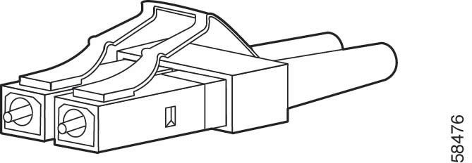
The following illustration shows a Lucent Connector (LC) style, fiber-optic cable connector.
 Warning |
Statement 1051—Laser Radiation Invisible laser radiation may be emitted from disconnected fibers or connectors. Do not stare into beams or view directly with optical instruments. |
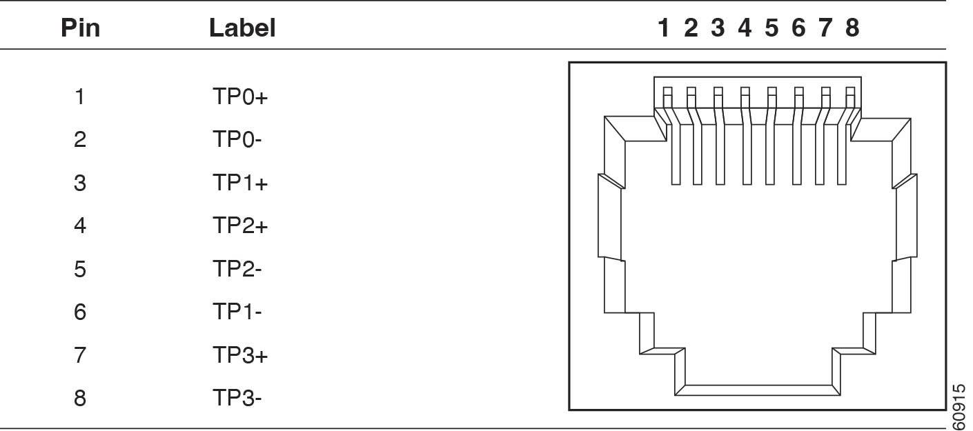
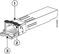
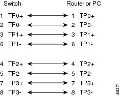
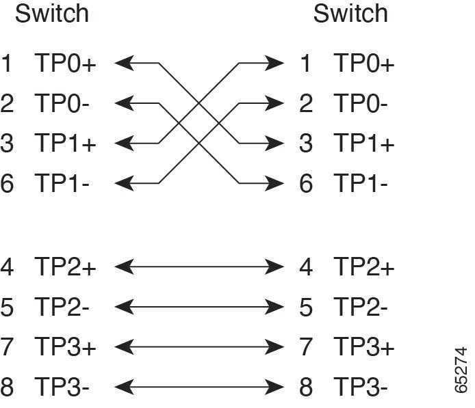
The following illustration shows the 1000BASE-T SFP module RJ-45 connector.
|
1 |
RJ-45 connector |
3 |
Bale-clasp latching mechanism in the open (unlocked) position |
|
2 |
Bale-clasp latching mechanism in the closed |
|
|
Console Port
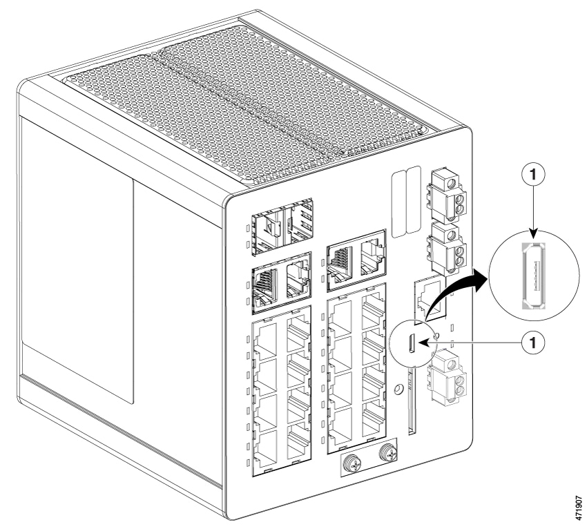
The switch has two console ports: a USB micro-Type B port and an RJ-45 console port, both on the front panel.
|
1 |
USB Micro-Type B Port |
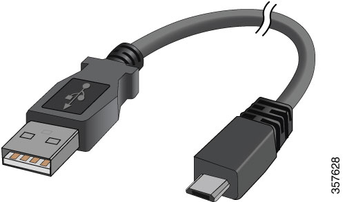
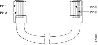
The USB console port uses a USB Type B to 5-pin micro-Type B cable, which is shown in the following illustration. The USB micro Type A-to-USB micro-Type B cable is not supplied.
 Note |
When running Linux, access the USB Console using Minicom instead of Screen . |
The RJ-45 console port uses an 8-pin RJ-45 connector. The supplied RJ-45-to-DB-9 adapter cable is used to connect the console port of the switch to a console PC. You must provide a RJ-45-to-DB-25 female DTE adapter if you want to connect the switch console port to a terminal. You can order a kit (part number ACS-DSBUASYN=) containing that adapter.
Alarm Port
The labels for the alarm connector pin-outs are on the switch panel and are displayed in the following table.
|
Label |
Connection |
|---|---|
|
NO |
Alarm Output Normally Open (NO) connection |
|
COM |
Alarm Output Common connection |
|
NC |
Alarm Output Normally Closed (NC) connection |
|
IN2 |
Alarm Input 2 |
|
REF |
Alarm Input Reference Ground connection |
|
IN1 |
Alarm Input 1 |
 Feedback