Configuring DHCP Relay in a BGP EVPN VXLAN Fabric

Information About DHCP Relay in a BGP EVPN VXLAN Fabric

Networks use DHCP relay to forward DHCP packets between host devices and a DHCP server. In a BGP EVPN VXLAN fabric, you can configure a VTEP as a relay agent to provide DCHP relay services in a multi-tenant VXLAN environment.

When a network uses DHCP relay, DHCP messages move through the same switch in both directions. DHCP relay generally uses the gateway IP address (GiAddr) for scope selection and DHCP response messages. In a BGP EVPN VXLAN fabric that has distributed IP anycast gateway enabled, DHCP messages can return to any switch that hosts the respective GiAddr.

Deploying DHCP relay in an EVPN VXLAN network requires a different method for scope selection and a unique IP address for each switch in the network. The unique Loopback interface for a switch becomes the GiAddr that a switch uses to respond to the correct switch. DHCP option 82, also referred to as DHCP option VPN, is used for scope selection based on the Layer 2 VNI.

In a multi-tenant EVPN environment, DHCP relay uses the following sub-options of option 82:

  • Sub-Option 151(0x97)—Virtual Subnet Selection:

    The virtual subnet selection sub-option is used to convey VRF-related information to the DHCP server in an MPLS VPN and a VXLAN EVPN multi-tenant environment.

    RFC 6607 provides the definition for this sub-option.

  • Sub-Option 11(0xb)—Server ID Override

    The server identifier or server ID override sub-option allows the DHCP relay agent to specify a new value for the server ID option. The DHCP server inserts this new value in the reply packet. This sub-option allows the DHCP relay agent to act as the actual DHCP server. The DHCP relay agent begins to receive all the renew requests instead of the DHCP server. The server ID override sub-option contains the incoming interface IP address. The DHCP client accesses the DHCP relay agent using the incoming interface IP address. The DHCP client uses this information to send all the renew and release request packets to the DHCP relay agent. The DHCP relay agent adds all the appropriate sub-options and then forwards the renew and release request packets to the original DHCP server.

    For this function, Cisco’s proprietary implementation is sub-option 152(0x98). To implement the suboption and manage the function, run the ip dhcp relay sub-option type cisco command in global configuration mode on the VTEP that acts as the DHCP relay agent.

    RFC 5107 provides the definition for this sub-option.

  • Sub-Option 5(0x5)—Link Selection:

    The link selection sub-option provides a mechanism to separate the subnet or link, on which the DHCP client resides, from the GiAddr. The DHCP server uses this mechanism to communicate with the DHCP relay agent. The DHCP relay agent sets the sub-option to the correct subscriber subnet. The DHCP server then uses this value to assign an IP address different from the GiAddr. The DHCP relay agent sets the GiAddr to its own IP address to ensure that it is possible to forward the DHCP messages over the network.

    For this function, Cisco’s proprietary implementation is sub-option 150(0x96). To manage the function, run the ip dhcp relay sub-option type cisco command in global configuration mode on the VTEP that acts as the DHCP relay agent.

    RFC 3527 provides the definition for this sub-option.

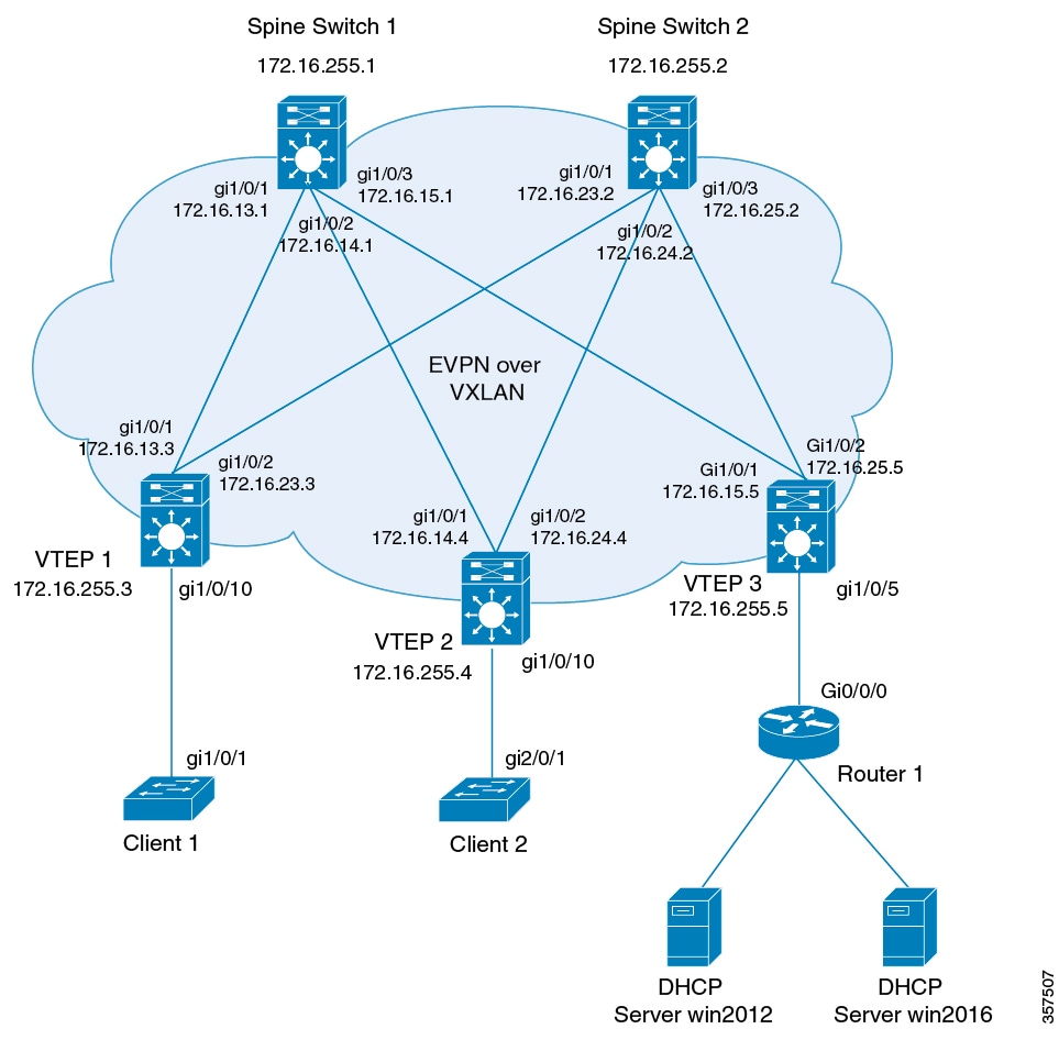
DHCP Relay on VTEPs in Distributed Anycast Gateway Deployment

DHCP relay is generally configured on the default gateway that faces the DHCP client. You can configure a VTEP as a DHCP relay agent in different ways to automate IP addressing. The configuration depends on whether the DHCP server is present in the same network, the same VRF, or a different VRF compared to the DHCP client. When the DHCP server and DHCP client are in different VRFs, traffic is forwarded across the tenant or VRF boundaries.

The following are the common DHCP relay deployment scenarios for a BGP EVPN VXLAN fabric:

  1. DHCP server is in the Layer 3 default VRF and DHCP client is in the tenant VRF.

    See Example: DHCP Server is in the Layer 3 Default VRF and the DHCP Client is in the Tenant VRF for a configuration example.

  2. DHCP server and DHCP client are in the same tenant VRF.

    See Example: DHCP Server and DHCP Client are in the Same Tenant VRF for a configuration example.

  3. DHCP server and DHCP client are in different tenant VRFs.

    See Example: DHCP Client and DHCP Server are in Different Tenant VRFs for a configuration example.

  4. DHCP server is in a non-default non-VXLAN VRF and DHCP client is in the tenant VRF.

    See Example: DHCP Server is in a non-Default, non-VXLAN VRF and DHCP Client is in the Tenant VRF for a configuration example.

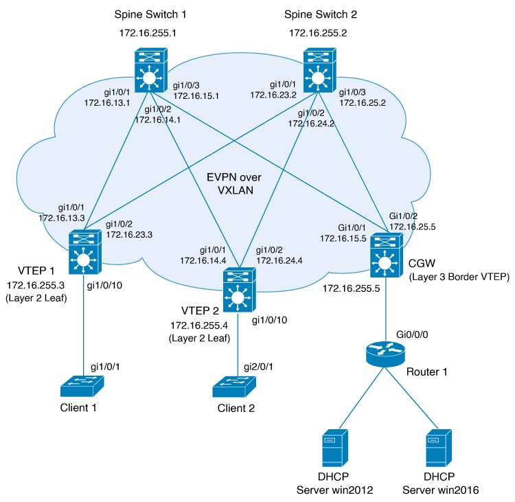
DHCP Relay on VTEPs in a Layer 2 Overlay Fabric

In an EVPN VXLAN centralized gateway (CGW) deployment, the CGW performs the Layer 3 gateway function for all the Layer 2 VNIs. All the other Leaf VTEPs in the network perform only bridging. The CGW VTEP acts as the Layer 3 gateway and performs routing for the intersubnet VXLAN traffic.

One of the VTEPs, usually a Border VTEP, is configured with an SVI to act as the Layer 3 gateway. You can also configure the Layer 3 gateway on an external router or a firewall that is connected to the Border Layer 2 VTEP, for policy enforcement and inspection of the intersubnet traffic.

DHCP follows the Discover, Offer, Request, Acknowledge (DORA) process to assign the IP addresses to the endpoints or hosts. To optimize the DORA sequence, a Layer 2 VTEP forwards the DHCP requests only to a Layer 3 VTEP. The Layer 2 VTEP uses the Gateway MAC-IP route (Route type 2 that is received with BGP gateway extended community attribute) to forward the packets to the Layer 3 gateway VTEP. The DHCP Relay on the Layer 3 gateway VTEP communicates with the DHCP server.

Starting with Cisco IOS XE 17.12.2, the following two configurations are supported.

How to Configure DHCP Relay in a BGP EVPN VXLAN Fabric

You must configure EVPN VXLAN Layer 2 and Layer 3 overlay networks before configuring BGP EVPN VXLAN interworking with DHCP relay. See Configuring EVPN VXLAN Integrated Routing and Bridging for detailed steps.

Perform the following set of procedures to configure BGP EVPN VLAN interworking with DHCP relay:

Configuring DHCP Relay on a VTEP

To configure DHCP relay on a VTEP, perform the following steps:

Procedure

  Command or Action Purpose

Step 1

enable

Example:

Device> enable

Enables privileged EXEC mode.

Enter your password, if prompted.

Step 2

configure terminal

Example:

Device# configure terminal

Enters global configuration mode.

Step 3

ip dhcp relay information option vpn

Example:

Device(config)# ip dhcp relay information option vpn

Adds option VPN suboption to DHCP option 82.

Enables the device to insert VPN suboptions into the DHCP relay agent information option in the messages forwarded to the DHCP server and sets the GiAddr on the outgoing interface towards the DHCP server.

Step 4

ip dhcp relay information option

Example:

Device(config)# ip dhcp relay information option

Enables DHCP option 82.

Enables the system to insert a DHCP relay agent information option in the messages forwarded to the DHCP server.

Step 5

ip dhcp relay override gateway-ip-address link-selection

Example:

Device(config)# ip dhcp relay override giaddr link-selection

Sets the gateway IP address as the IP address of the DHCP relay agent and configures the server to assign an IP address that is different from the GiAddr to the DHCP clients.

Step 6

ip dhcp compatibility suboption { link-selection | server-override} standard

Example:

Device(config)# ip dhcp compatibility suboption link-selection standard
Device(config)# ip dhcp compatibility suboption server-override standard

Configures the DHCP client to use the Internet Assigned Numbers Authority (IANA) standard relay agent server ID override suboption.

Use the link-selection standard keyword to switch to standard DHCP option 82[5].

Use the server-override standard keyword to switch to standard DHCP option 82[11].

Step 7

ip dhcp snooping vlan vlan-id-list

Example:

Device(config)# ip dhcp snooping vlan 201-202

Enables DHCP snooping on the specified list of VLANs.

Note


VLAN id used for core SVI (L3 VNI) should not be enabled with DHCP snooping.

Step 8

ip dhcp snooping

Example:

Device(config)# ip dhcp snooping

Enables DHCP snooping globally on the VTEP.

Step 9

end

Example:

Device(config)# end

Returns to privileged EXEC mode.

Configuring DHCP Relay on the Access SVI of a VTEP

Perform this procedure on all the VTEPs for each VLAN that is associated with the Layer 2 VNI configured in the EVPN VXLAN network.

To configure DHCP relay on the access SVI of a VTEP, perform the following steps:

Procedure

  Command or Action Purpose

Step 1

enable

Example:

Device> enable

Enables privileged EXEC mode.

Enter your password, if prompted.

Step 2

configure terminal

Example:

Device# configure terminal

Enters global configuration mode.

Step 3

interface vlan vlan-id

Example:

Device(config)# interface Vlan 201

Enters interface configuration mode for the specified VLAN interface.

This VLAN interface acts as the GiAddr.

Step 4

vrf forwarding vrf-name

Example:

Device(config-if)# vrf forwarding green

Associates the VRF with the interface.

The interface must be associated with the same VRF for which the Layer 3 VNI has been configured for the EVPN VXLAN network.

Step 5

ip dhcp relay information option vpn-id

Example:

Device(config-if)# ip dhcp relay information option vpn-id

Enables the device to insert VPN suboptions into the DHCP relay agent information option in the messages forwarded to the DHCP server and sets the GiAddr on the outgoing interface towards the DHCP server.

Step 6

ip dhcp relay source-interface Loopback loopback-interface-id

Example:

Device(config-if)# ip dhcp relay source-interface Loopback13

Configures the specified Loopback interface as the source interface for DHCP relay messages. The DHCP relay agent uses the IP address of the source interface as the source IP address to relay messages.

Note


The IP address configured on the Loopback interface must be unique per VTEP per VRF.

Step 7

ip address ip-address

Example:

Device(config-if)# ip address 192.168.1.201 255.255.255.0

Sets the IP address for the VLAN interface.

Step 8

ip helper-address [ global | vrf vrf-name] ip-address

Example:

Device(config-if)# ip helper-address global 192.168.3.100
Device(config-if)# ip helper-address vrf green 192.168.20.20

Sets the DHCP IP helper address for the VLAN interface.

Use the global keyword if the DHCP server is reachable over the global routing table (GRT).

Use the vrf vrf-name keyword if the DHCP server is reachible over the tenant VRF.

Step 9

exit

Example:

Device(config-if)# exit

Exits interface configuration mode and returns to global configuration mode.

Step 10

end

Example:

Device(config)# end

Returns to privileged EXEC mode.

Configuring the Layer 3 or Routed Interface on the Border VTEP for DHCP Server Reachability

DHCP server reachability can be achieved through a physical Layer 3 interface (or subinterface), a dot1Q interface, an SVI, or a Layer 3 Portchannel interface (or subinterface).


Note


This task is optional if you implement plain IP address forwarding in the respective VRF.


To configure the Layer 3 or routed interface on the border VTEP for external connectivity, perform the following steps:

Procedure

  Command or Action Purpose

Step 1

enable

Example:

Device> enable

Enables privileged EXEC mode.

Enter your password, if prompted.

Step 2

configure terminal

Example:

Device# configure terminal

Enters global configuration mode.

Step 3

interface vlan vlan-id

Example:

Device(config)# interface vlan 203

Enters interface configuration mode for the specified VLAN interface.

Step 4

vrf forwarding vrf-name

Example:

Device(config-if)# vrf forwarding green

Configures the SVI for the VLAN and associates the specified VRF with the interface.

Step 5

ip address ip-address

Example:

Device(config-if)# ip address 192.168.3.203 255.255.255.0

Configures the IP address for the VLAN.

Step 6

ipv6 address ipv6-address

Example:

Device(config-if)# ipv6 address 2001:203::203/64

Configures the IPv6 address for the VLAN.

Step 7

ipv6 enable

Example:

Device(config-if)# ipv6 enable

Enables IPv6 processing on the VLAN interface.

Step 8

exit

Example:

Device(config-if)# exit

Exits interface configuration mode and returns to global configuration mode.

Step 9

interface interface-id

Example:

Device(config)# interface GigabitEthernet1/0/30

Enters interface configuration mode for the specified interface.

Step 10

switchport access vlan vlan-id

Example:

Device(config-if)# switchport access vlan 203

Specifies the VLAN to be used as access VLAN when the interface is in access mode.

Step 11

switchport mode access

Example:

Device(config-if)# switchport mode access

Configures the interface as an access interface.

Step 12

exit

Example:

Device(config-if)# exit

Exits interface configuration mode and returns to global configuration mode.

Step 13

end

Example:

Device(config)# end

Returns to privileged EXEC mode.

Configuration Examples for DHCP Relay in a BGP EVPN VXLAN Fabric

This section provides configuration examples for DHCP relay in a BGP EVPN VXLAN fabric for the following scenarios using the topology in DHCP Relay Deployment in a BGP EVPN VXLAN Fabric.

Figure 1. DHCP Relay Deployment in a BGP EVPN VXLAN Fabric
Topology for DHCP relay deployment in a BGP EVPN VXLAN fabric

The preceding figure shows an EVPN VXLAN network with two spine switches (Spine Switch 1 and Spine Switch 2) and three leaf switches (VTEP1, VTEP 2, and VTEP 3). VTEP 3 is connected to two DHCP servers. VTEP 1 and VTEP 2 are connected to a single DHCP client each.

Example: DHCP Server is in the Layer 3 Default VRF and the DHCP Client is in the Tenant VRF

This example shows how to configure DHCP relay deployment in a BGP EVPN VXLAN fabric for the topology in this figure when the DHCP server and the DHCP client are in the same tenant VRF. The DHCP server is reachable over global routing table (GRT).

The following tables provide sample configurations for the DHCP server and VTEP 1:


Note


VLAN id used for core SVI (L3 VNI) should not be enabled with DHCP snooping.


Table 1. Configuring DHCP when DHCP Server is in the Layer 3 Default VRF and DHCP Client is in the Tenant VRF

DHCP Configuration Snippet

<snip: only the relevant configuration is shown>

ip dhcp-relay source-interface Loopback0
ip dhcp relay information option vpn
ip dhcp relay information option
ip dhcp compatibility suboption link-selection standard
ip dhcp compatibility suboption server-override standard
ip dhcp snooping vlan 101-102,201-202
ip dhcp snooping
!
interface Loopback0
  ip address 172.16.255.3 255.255.255.255
  ip ospf 1 area 0
!
interface Vlan101
  vrf forwarding green
  ip address 10.1.101.1 255.255.255.0
  ip helper-address global 192.168.20.20
!
interface Vlan102
  vrf forwarding green
  ip address 10.1.102.1 255.255.255.0
  ip helper-address global 192.168.20.20
!
interface Vlan201
  vrf forwarding red
  ip address 10.2.201.1 255.255.255.0
  ip helper-address global 192.168.20.20
!
<snip: only the relevant configuration is shown>
Table 2. Configuring VTEP 1 when DHCP Server is in the Layer 3 Default VRF and DHCP Client is in the Tenant VRF

VTEP 1


Leaf-01# show running-config
!
hostname Leaf-01
!
vrf definition green
rd 1:1
!
address-family ipv4
route-target export 1:1
route-target import 1:1
route-target export 1:1 stitching
route-target import 1:1 stitching
exit-address-family
!
vrf definition red
rd 2:2
!
address-family ipv4
route-target export 2:2
route-target import 2:2
route-target export 2:2 stitching
route-target import 2:2 stitching
exit-address-family
!
ip routing
!
ip multicast-routing
!
ip dhcp-relay source-interface Loopback0
ip dhcp relay information option vpn
ip dhcp relay information option
ip dhcp compatibility suboption link-selection standard
ip dhcp compatibility suboption server-override standard
!
ip dhcp snooping vlan 101-102,201-202
ip dhcp snooping
!
l2vpn evpn
replication-type static
router-id Loopback1
default-gateway advertise
!
l2vpn evpn instance 101 vlan-based
encapsulation vxlan
!
l2vpn evpn instance 102 vlan-based
encapsulation vxlan
!
l2vpn evpn instance 201 vlan-based
encapsulation vxlan
!
l2vpn evpn instance 202 vlan-based
encapsulation vxlan
!
system mtu 9198
!
vlan configuration 101
member evpn-instance 101 vni 10101
vlan configuration 102
member evpn-instance 102 vni 10102
vlan configuration 201
member evpn-instance 201 vni 10201
vlan configuration 202
member evpn-instance 202 vni 10202
vlan configuration 901
member vni 50901
vlan configuration 902
member vni 50902
!
interface Loopback0
ip address 172.16.255.3 255.255.255.255
ip ospf 1 area 0
!
interface Loopback1
ip address 172.16.254.3 255.255.255.255
ip pim sparse-mode
ip ospf 1 area 0

!
interface GigabitEthernet1/0/1
no switchport
ip address 172.16.13.3 255.255.255.0
ip pim sparse-mode
ip ospf network point-to-point
ip ospf 1 area 0
!
interface GigabitEthernet1/0/2
no switchport
ip address 172.16.23.3 255.255.255.0
ip pim sparse-mode
ip ospf network point-to-point
ip ospf 1 area 0
!
interface GigabitEthernet1/0/10
switchport mode trunk
!
interface Vlan101
vrf forwarding green
ip address 10.1.101.1 255.255.255.0
ip helper-address global 192.168.20.20
!
interface Vlan102
vrf forwarding green
ip address 10.1.102.1 255.255.255.0
ip helper-address global 192.168.20.20
!
interface Vlan201
vrf forwarding red
ip address 10.2.201.1 255.255.255.0
ip helper-address global 192.168.20.20
!
interface Vlan202
vrf forwarding red
ip address 10.2.202.1 255.255.255.0
ip helper-address global 192.168.20.20
!
interface Vlan901
vrf forwarding green
ip unnumbered Loopback0
no autostate
!
interface Vlan902
vrf forwarding red
ip unnumbered Loopback0
no autostate
!
!
interface nve1
no ip address
source-interface Loopback1
host-reachability protocol bgp
member vni 10101 mcast-group 225.0.0.101
member vni 10102 mcast-group 225.0.0.102
member vni 10201 mcast-group 225.0.0.201
member vni 10202 mcast-group 225.0.0.202
member vni 50901 vrf green
member vni 50902 vrf red
!
router ospf 1
router-id 172.16.255.3
!
router bgp 65001
bgp router-id interface Loopback0
bgp log-neighbor-changes
no bgp default ipv4-unicast
neighbor 172.16.255.1 remote-as 65001
neighbor 172.16.255.1 update-source Loopback0
neighbor 172.16.255.2 remote-as 65001
neighbor 172.16.255.2 update-source Loopback0
!
address-family ipv4
exit-address-family
!
address-family l2vpn evpn
neighbor 172.16.255.1 activate
neighbor 172.16.255.1 send-community both
neighbor 172.16.255.2 activate
neighbor 172.16.255.2 send-community both
exit-address-family
!
address-family ipv4 vrf green
advertise l2vpn evpn
redistribute connected
redistribute static
exit-address-family
!
address-family ipv4 vrf red
advertise l2vpn evpn
redistribute connected
redistribute static
exit-address-family
!
ip pim rp-address 172.16.255.255
!
end

Leaf-01# 

Return to Configuration Examples for DHCP Relay in a BGP EVPN VXLAN Fabric.

Example: DHCP Server and DHCP Client are in the Same Tenant VRF

This example shows how to configure DHCP relay deployment in a BGP EVPN VXLAN fabric for the topology in this figure when the DHCP server and the DHCP client are in the same tenant VRF. The DHCP server is reachable over this common tenant VRF.

The following tables provide sample configurations for the DHCP server and VTEP 1:


Note


VLAN id used for core SVI (L3 VNI) should not be enabled with DHCP snooping.


Table 3. Configuring DHCP when DHCP Server and DHCP Client are in the Same Tenant VRF

DHCP Configuration Snippet

<snip: only the relevant configuration is shown>

ip dhcp relay information option vpn
ip dhcp relay information option
ip dhcp compatibility suboption link-selection standard
ip dhcp compatibility suboption server-override standard
ip dhcp snooping vlan 101-102,201-202
ip dhcp snooping
!
interface Loopback101
  vrf forwarding green
  ip address 10.1.251.1 255.255.255.255
!
interface Vlan101
  vrf forwarding green
  ip dhcp relay source-interface Loopback101
  ip address 10.1.101.1 255.255.255.0
  ip helper-address 192.168.20.20
!
interface Vlan102
  vrf forwarding green
  ip dhcp relay source-interface Loopback101
  ip address 10.1.102.1 255.255.255.0
  ip helper-address 192.168.20.20

<snip: only the relevant configuration is shown>
Table 4. Configuring VTEP 1 when DHCP Server and DHCP Client are in the Same Tenant VRF

VTEP 1


Leaf-01# show running-config
!
hostname Leaf-01
!
vrf definition green
rd 1:1
!
address-family ipv4
route-target export 1:1
route-target import 1:1
route-target export 1:1 stitching
route-target import 1:1 stitching
exit-address-family
!
ip routing
!
ip multicast-routing
!
ip dhcp relay information option vpn
ip dhcp relay information option
ip dhcp compatibility suboption link-selection standard
ip dhcp compatibility suboption server-override standard
!
ip dhcp snooping vlan 101-102,201-202
ip dhcp snooping
!
l2vpn evpn
replication-type static
router-id Loopback1
default-gateway advertise
!
l2vpn evpn instance 101 vlan-based
encapsulation vxlan
!
l2vpn evpn instance 102 vlan-based
encapsulation vxlan
!
l2vpn evpn instance 201 vlan-based
encapsulation vxlan
!
l2vpn evpn instance 202 vlan-based
encapsulation vxlan
!
system mtu 9198
!
vlan configuration 101
member evpn-instance 101 vni 10101
vlan configuration 102
member evpn-instance 102 vni 10102
vlan configuration 201
member evpn-instance 201 vni 10201
vlan configuration 202
member evpn-instance 202 vni 10202
vlan configuration 901
member vni 50901
vlan configuration 902
member vni 50902
!
interface Loopback0
ip address 172.16.255.3 255.255.255.255
ip ospf 1 area 0
!
interface Loopback1
ip address 172.16.254.3 255.255.255.255
ip pim sparse-mode
ip ospf 1 area 0
!
interface Loopback101
vrf forwarding green
ip address 10.1.251.1 255.255.255.255
!
interface GigabitEthernet1/0/1
no switchport
ip address 172.16.13.3 255.255.255.0
ip pim sparse-mode
ip ospf network point-to-point
ip ospf 1 area 0
!
interface GigabitEthernet1/0/2
no switchport
ip address 172.16.23.3 255.255.255.0
ip pim sparse-mode
ip ospf network point-to-point
ip ospf 1 area 0
!
interface GigabitEthernet1/0/10
switchport mode trunk
!
interface Vlan101
vrf forwarding green
ip dhcp relay source-interface Loopback101
ip address 10.1.101.1 255.255.255.0
ip helper-address 192.168.20.20
!
interface Vlan102
vrf forwarding green
ip dhcp relay source-interface Loopback101
ip address 10.1.102.1 255.255.255.0
ip helper-address 192.168.20.20
!
interface Vlan901
vrf forwarding green
ip unnumbered Loopback0
no autostate
!

interface nve1
no ip address
source-interface Loopback1
host-reachability protocol bgp
member vni 10101 mcast-group 225.0.0.101
member vni 10102 mcast-group 225.0.0.102
member vni 50901 vrf green
!
router ospf 1
router-id 172.16.255.3
!
router bgp 65001
bgp router-id interface Loopback0
bgp log-neighbor-changes
no bgp default ipv4-unicast
neighbor 172.16.255.1 remote-as 65001
neighbor 172.16.255.1 update-source Loopback0
neighbor 172.16.255.2 remote-as 65001
neighbor 172.16.255.2 update-source Loopback0
!
address-family ipv4
exit-address-family
!
address-family l2vpn evpn
neighbor 172.16.255.1 activate
neighbor 172.16.255.1 send-community both
neighbor 172.16.255.2 activate
neighbor 172.16.255.2 send-community both
exit-address-family
!
address-family ipv4 vrf green
advertise l2vpn evpn
redistribute connected
redistribute static
exit-address-family
!
ip pim rp-address 172.16.255.255
!
end
!
Leaf-01# 

Return to Configuration Examples for DHCP Relay in a BGP EVPN VXLAN Fabric.

Example: DHCP Client and DHCP Server are in Different Tenant VRFs

This example shows how to configure DHCP relay deployment in a BGP EVPN VXLAN fabric for the topology in this figure when the DHCP server and the DHCP client are in different tenant VRFs. The DHCP server is reachable over a VRF that is different from the client's VRF.

The following tables provide sample configurations for the DHCP server and VTEP 1:


Note


VLAN id used for core SVI (L3 VNI) should not be enabled with DHCP snooping.


Table 5. Configuring DHCP when DHCP Server and DHCP Client are in Different Tenant VRFs

DHCP Configuration Snippet

<snip: only the relevant configuration is shown>

ip dhcp relay information option vpn
ip dhcp relay information option
ip dhcp compatibility suboption link-selection standard
ip dhcp compatibility suboption server-override standard
ip dhcp snooping vlan 101-102,201-202
ip dhcp snooping
!
interface Loopback101
vrf forwarding green
ip address 10.1.251.1 255.255.255.255
!
interface Vlan201
vrf forwarding red
ip dhcp relay source-interface Loopback101
ip address 10.2.201.1 255.255.255.0
ip helper-address vrf green 192.168.20.20

<snip: only the relevant configuration is shown>
Table 6. Configuring VTEP 1 when DHCP Server and DHCP Client are in Different Tenant VRFs

VTEP 1

Leaf-01# show running-config
!
hostname Leaf-01
!
vrf definition green
rd 1:1
!
address-family ipv4
route-target export 1:1
route-target import 1:1
route-target export 1:1 stitching
route-target import 1:1 stitching
exit-address-family
!
vrf definition red
rd 2:2
!
address-family ipv4
route-target export 2:2
route-target import 2:2
route-target export 2:2 stitching
route-target import 2:2 stitching
exit-address-family
!
ip routing
!
ip multicast-routing
!
ip dhcp relay information option vpn
ip dhcp relay information option
ip dhcp compatibility suboption link-selection standard
ip dhcp compatibility suboption server-override standard
!
ip dhcp snooping vlan 101-102,201-202
ip dhcp snooping
!
l2vpn evpn
replication-type static
router-id Loopback1
default-gateway advertise
!
l2vpn evpn instance 101 vlan-based
encapsulation vxlan
!
l2vpn evpn instance 102 vlan-based
encapsulation vxlan
!
l2vpn evpn instance 201 vlan-based
encapsulation vxlan
!
l2vpn evpn instance 202 vlan-based
encapsulation vxlan
!
system mtu 9198
!
vlan configuration 101
member evpn-instance 101 vni 10101
vlan configuration 102
member evpn-instance 102 vni 10102
vlan configuration 201
member evpn-instance 201 vni 10201
vlan configuration 202
member evpn-instance 202 vni 10202
vlan configuration 901
member vni 50901
vlan configuration 902
member vni 50902
!
interface Loopback0
ip address 172.16.255.3 255.255.255.255
ip ospf 1 area 0
!
interface Loopback1
ip address 172.16.254.3 255.255.255.255
ip pim sparse-mode
ip ospf 1 area 0

!
interface Loopback101
vrf forwarding green
ip address 10.1.251.1 255.255.255.255

!
interface GigabitEthernet1/0/1
no switchport
ip address 172.16.13.3 255.255.255.0
ip pim sparse-mode
ip ospf network point-to-point
ip ospf 1 area 0
!
interface GigabitEthernet1/0/2
no switchport
ip address 172.16.23.3 255.255.255.0
ip pim sparse-mode
ip ospf network point-to-point
ip ospf 1 area 0
!
interface GigabitEthernet1/0/10
switchport mode trunk
!

interface Vlan101
vrf forwarding green
ip dhcp relay source-interface Loopback101
ip address 10.1.101.1 255.255.255.0
ip helper-address 192.168.20.20
!
interface Vlan102
vrf forwarding green
ip dhcp relay source-interface Loopback101
ip address 10.1.102.1 255.255.255.0
ip helper-address 192.168.20.20

interface Vlan201
vrf forwarding red
ip dhcp relay source-interface Loopback101
ip address 10.2.201.1 255.255.255.0
ip helper-address vrf green 192.168.20.20
!
interface Vlan202
vrf forwarding red
ip dhcp relay source-interface Loopback101
ip address 10.2.202.1 255.255.255.0
ip helper-address vrf green 192.168.20.20
!
interface Vlan901
vrf forwarding green
ip unnumbered Loopback0
no autostate
!
interface Vlan902
vrf forwarding red
ip unnumbered Loopback0
no autostate
!
!
interface nve1
no ip address
source-interface Loopback1
host-reachability protocol bgp
member vni 10101 mcast-group 225.0.0.101
member vni 10102 mcast-group 225.0.0.102
member vni 10201 mcast-group 225.0.0.201
member vni 10202 mcast-group 225.0.0.202
member vni 50901 vrf green
member vni 50902 vrf red
!
router ospf 1
router-id 172.16.255.3
!
router bgp 65001
bgp router-id interface Loopback0
bgp log-neighbor-changes
no bgp default ipv4-unicast
neighbor 172.16.255.1 remote-as 65001
neighbor 172.16.255.1 update-source Loopback0
neighbor 172.16.255.2 remote-as 65001
neighbor 172.16.255.2 update-source Loopback0
!
address-family ipv4
exit-address-family
!
address-family l2vpn evpn
neighbor 172.16.255.1 activate
neighbor 172.16.255.1 send-community both
neighbor 172.16.255.2 activate
neighbor 172.16.255.2 send-community both
exit-address-family
!
address-family ipv4 vrf green
advertise l2vpn evpn
redistribute connected
redistribute static
exit-address-family
!
address-family ipv4 vrf red
advertise l2vpn evpn
redistribute connected
redistribute static
exit-address-family
!
ip pim rp-address 172.16.255.255
!
end
Leaf-01# 

Return to Configuration Examples for DHCP Relay in a BGP EVPN VXLAN Fabric.

Example: DHCP Server is in a non-Default, non-VXLAN VRF and DHCP Client is in the Tenant VRF

This example shows how to configure DHCP relay deployment in a BGP EVPN VXLAN fabric for the topology in this figure when the DHCP server is in a non-default, non-VXLAN VRF and the DHCP client is in the tenant VRF. The DHCP server is reachable over a VRF that is different from the client's VRF.

The following tables provide sample configurations for the DHCP server and VTEP 1:


Note


VLAN id used for core SVI (L3 VNI) should not be enabled with DHCP snooping.


Table 7. Configuring DHCP when DHCP Server is in a non-Default, non-VXLAN VRF and DHCP Client is in the Tenant VRF

DHCP Configuration Snippet

<snip: only the relevant configuration is shown>

ip dhcp relay information option vpn
ip dhcp relay information option
ip dhcp compatibility suboption link-selection standard
ip dhcp compatibility suboption server-override standard
ip dhcp snooping vlan 101-102,201-202
ip dhcp snooping
!
interface Loopback101
vrf forwarding green
ip address 10.1.251.1 255.255.255.255
!
interface Vlan201
vrf forwarding red
ip dhcp relay source-interface Loopback101
ip address 10.2.201.1 255.255.255.0
ip helper-address vrf green 192.168.20.20

<snip: only the relevant configuration is shown>
Table 8. Configuring VTEP 1 when the DHCP Server is in a non-Default, non-VXLAN VRF and the DHCP Client is in the Tenant VRF

VTEP 1

Leaf-01# show running-config
!
hostname Leaf-01
!
vrf definition green
rd 1:1
!
address-family ipv4
route-target export 1:1
route-target import 1:1
route-target export 1:1 stitching
route-target import 1:1 stitching
exit-address-family
!
vrf definition red
rd 2:2
!
address-family ipv4
route-target export 2:2
route-target import 2:2
route-target export 2:2 stitching
route-target import 2:2 stitching
exit-address-family
!
ip routing
!
ip multicast-routing
!
ip dhcp relay information option vpn
ip dhcp relay information option
ip dhcp compatibility suboption link-selection standard
ip dhcp compatibility suboption server-override standard
!
ip dhcp snooping vlan 101-102,201-202
ip dhcp snooping
!
l2vpn evpn
replication-type static
router-id Loopback1
default-gateway advertise
!
l2vpn evpn instance 101 vlan-based
encapsulation vxlan
!
l2vpn evpn instance 102 vlan-based
encapsulation vxlan
!
l2vpn evpn instance 201 vlan-based
encapsulation vxlan
!
l2vpn evpn instance 202 vlan-based
encapsulation vxlan
!
system mtu 9198
!
vlan configuration 101
member evpn-instance 101 vni 10101
vlan configuration 102
member evpn-instance 102 vni 10102

vlan configuration 201
member evpn-instance 201 vni 10201
vlan configuration 202
member evpn-instance 202 vni 10202
vlan configuration 901
member vni 50901
vlan configuration 902
member vni 50902
!
interface Loopback0
ip address 172.16.255.3 255.255.255.255
ip ospf 1 area 0
!
interface Loopback1
ip address 172.16.254.3 255.255.255.255
ip pim sparse-mode
ip ospf 1 area 0

!
interface Loopback101
vrf forwarding green
ip address 10.1.251.1 255.255.255.255

!
interface GigabitEthernet1/0/1
no switchport
ip address 172.16.13.3 255.255.255.0
ip pim sparse-mode
ip ospf network point-to-point
ip ospf 1 area 0
!
interface GigabitEthernet1/0/2
no switchport
ip address 172.16.23.3 255.255.255.0
ip pim sparse-mode
ip ospf network point-to-point
ip ospf 1 area 0
!
interface GigabitEthernet1/0/10
switchport mode trunk
!

interface Vlan101
vrf forwarding green
ip dhcp relay source-interface Loopback101
ip address 10.1.101.1 255.255.255.0
ip helper-address 192.168.20.20
!
interface Vlan102
vrf forwarding green
ip dhcp relay source-interface Loopback101
ip address 10.1.102.1 255.255.255.0
ip helper-address 192.168.20.20

interface Vlan201
vrf forwarding red
ip dhcp relay source-interface Loopback101
ip address 10.2.201.1 255.255.255.0
ip helper-address vrf green 192.168.20.20
!
interface Vlan202
vrf forwarding red
ip dhcp relay source-interface Loopback101
ip address 10.2.202.1 255.255.255.0
ip helper-address vrf green 192.168.20.20
!
interface Vlan901
vrf forwarding green
ip unnumbered Loopback0
no autostate
!
interface Vlan902
vrf forwarding red
ip unnumbered Loopback0
no autostate
!
!
interface nve1
no ip address
source-interface Loopback1
host-reachability protocol bgp
member vni 10101 mcast-group 225.0.0.101
member vni 10102 mcast-group 225.0.0.102
member vni 10201 mcast-group 225.0.0.201
member vni 10202 mcast-group 225.0.0.202
member vni 50901 vrf green
member vni 50902 vrf red
!
router ospf 1
router-id 172.16.255.3
!
router bgp 65001
bgp router-id interface Loopback0
bgp log-neighbor-changes
no bgp default ipv4-unicast
neighbor 172.16.255.1 remote-as 65001
neighbor 172.16.255.1 update-source Loopback0
neighbor 172.16.255.2 remote-as 65001
neighbor 172.16.255.2 update-source Loopback0
!
address-family ipv4
exit-address-family
!
address-family l2vpn evpn
neighbor 172.16.255.1 activate
neighbor 172.16.255.1 send-community both
neighbor 172.16.255.2 activate
neighbor 172.16.255.2 send-community both
exit-address-family
!

address-family ipv4 vrf green
advertise l2vpn evpn
redistribute connected
redistribute static
exit-address-family
!
address-family ipv4 vrf red
advertise l2vpn evpn
redistribute connected
redistribute static
exit-address-family
!
ip pim rp-address 172.16.255.255
!
end
Leaf-01# 

Return to Configuration Examples for DHCP Relay in a BGP EVPN VXLAN Fabric.

Example: Layer 3 Gateway Configured on Border VTEP

This section shows how to configure a DHCP Relay in a Layer 2 overlay fabric, when the CGW, which is the Layer 3 gateway, is configured on the border VTEP. In this topology, the Layer 2 VTEPs relay the DHCP packets to the Border Layer 3 VTEP.

Figure 2. Layer 3 Gateway Configured on Border VTEP
DHCP Relay when the Layer 3 Gateway (CGW) is configured on the Layer 3 Border VTEP

The following tables provide a snippet of the sample configurations for the Border VTEP (Layer 3 Gateway) and Leaf VTEP.


Note


VLAN id used for core SVI (L3 VNI) should not be enabled with DHCP snooping.


Table 9. DHCP Configuration on Leaf VTEP

Leaf Layer 2 VTEP Configuration Snippet

<snip: only the relevant configuration is shown>
ip dhcp relay information option vpn
ip dhcp relay information option
ip dhcp compatibility suboption link-selection standard
ip dhcp compatibility suboption server-override standard
ip dhcp snooping vlan 101-102
ip dhcp snooping
!
Table 10. DHCP Configuration on Layer 3 Border VTEP

Layer 3 Border VTEP (CGW) Configuration Snippet

<snip: only the relevant configuration is shown>
ip dhcp-relay source-interface Loopback0
ip dhcp relay information option vpn
ip dhcp relay information option
ip dhcp compatibility suboption link-selection standard
ip dhcp compatibility suboption server-override standard
ip dhcp snooping vlan 101-102,201-202
ip dhcp snooping
!
interface Loopback0
ip address 172.16.255.5 255.255.255.255
ip ospf 1 area 0
!
interface Vlan101
description Layer 3 gateway for vni 10101
ip address 10.1.101.1 255.255.255.0
ip helper-address global 192.168.20.20
!

Example: Layer 3 Gateway Configured on External Router or Firewall

This section shows how to configure a DHCP Relay in a Layer 2 overlay fabric, when the CGW, which is the Layer 3 gateway, is configured on an external router or a firewall. In this topology, all the VTEPs perform Layer 2 bridging. A Layer 2 Border VTEP connects to the external router that acts as a Layer 3 gateway. The Layer 2 Border node advertises a Route Type 2 (RT2) with default gateway extended community.

Figure 3. Layer 3 Gateway Configured on External Router
DHCP Relay when Layer 3 Gateway (CGW) is configured on an external router

The following tables provide a snippet of the sample configurations for the Layer 2 Border VTEP and Leaf VTEP.

Table 11. DHCP Configuration on Leaf VTEP

Leaf VTEP Configuration Snippet

<snip: only the relevant configuration is shown>
ip dhcp relay information option vpn
ip dhcp relay information option
ip dhcp compatibility suboption link-selection standard
ip dhcp compatibility suboption server-override standard
ip dhcp snooping vlan 101-102
ip dhcp snooping
VTEP-2#sh run | s dhcp
ip dhcp snooping vlan 101 #-------------- globally
ip dhcp snooping #----------------------- globally

on DHCP Gateway facing port:
VTEP-2#sh run int g1/0/43
Building configuration...

Current configuration : 139 bytes
!
interface GigabitEthernet1/0/43
 switchport access vlan 101
 switchport mode access
 spanning-tree portfast
 ip dhcp snooping trust #-----------------make trusted port GW port
end
VTEP-2#sh run | s ip access-list
ip access-list extended gatewayiplist #------------- ACL
 10 permit ip host 192.168.101.1 any
VTEP-2#
VTEP-2#sh run | s route-map     
route-map GW_MAC_IP_TRACKING permit 10 #------------Route Map
 match ip address gatewayiplist
 match evpn route-type 2-mac-ip
 set extcommunity default-gw

VTEP-2#sh run | s r b
router bgp 65001
 bgp log-neighbor-changes
 no bgp default ipv4-unicast
 neighbor 172.16.255.1 remote-as 65001
 neighbor 172.16.255.1 update-source Loopback0
 !
 address-family ipv4
 exit-address-family
 !
 address-family l2vpn evpn
  neighbor 172.16.255.1 activate
  neighbor 172.16.255.1 send-community both
  neighbor 172.16.255.1 route-map GW_MAC_IP_TRACKING out #----------Apply route Map to L2VPN neighbor 
 exit-address-family


**NOTE: If VRF configured on VTEPs then option 82 is needed, in that case you need below additional commands on VTEP-2.
If it is "flat" network not needed:
ip dhcp relay information option vpn
ip dhcp relay information option
ip dhcp compatibility suboption link-selection standard
ip dhcp compatibility suboption server-override standard

**Genral debugs used**
  debug ip dhcp server packet detail
  debug ip dhcp server packet
  debug ip dhcp server events
  debug ip dhcp snooping packet
  debug dhcp detail

**To verify check on VTEP-1**
VTEP-1#sh l2vpn evpn default-gateway
Valid Default Gateway Address                 EVI   VLAN  MAC Address    Source
----- --------------------------------------- ----- ----- -------------- -----------
  Y   192.168.101.1                           101   101   4488.16ff.d7c1 172.16.254.2 #---------"Y" is VALID  
Table 12. DHCP Configuration on Layer 2 Border VTEP

Layer 2 Border VTEP Configuration Snippet

<snip: only the relevant configuration is shown>


ip dhcp relay information option vpn
ip dhcp relay information option
ip dhcp compatibility suboption link-selection standard
ip dhcp compatibility suboption server-override standard
ip dhcp snooping vlan 101-102
ip dhcp snooping

    ! Configure an access list and route-map to match and set default-gw attribute
 
ip access-list extended gatewayiplist
 10 permit ip host 192.168.3.100 any
 
route-map GW_MAC_IP_TRACKING permit 10
 match ip address gatewayiplist
 match evpn route-type 2-mac-ip
 set extcommunity default-gw
 
    ! Attach the route-map to the neighbor

router bgp 65001
bgp router-id interface Loopback0 bgp log-neighbor-changes
no bgp default ipv4-unicast
neighbor 172.16.255.1 remote-as 65001 neighbor 172.16.255.1 update-source Loopback0 neighbor 172.16.255.2 remote-as 65001 neighbor 172.16.255.2 update-source Loopback0
!
address-family ipv4 exit-address-family
!
address-family l2vpn evpn neighbor 172.16.255.1 activate
neighbor 172.16.255.1 send-community both 
neighbor 172.16.255.1 route-map GW_MAC_IP_TRACKING out 
neighbor 172.16.255.2 activate
neighbor 172.16.255.2 send-community both 
neighbor 172.16.255.2 route-map GW_MAC_IP_TRACKING out 
exit-address-family

Additional References for DHCP Relay in a BGP EVPN VXLAN Fabric

Related Documents

Related Topic

Document Title

DHCP Server configuration in IOS XE EVPN VXLAN

Configure DHCP in IOS XE EVPN/VXLAN