Configuring Interface Characteristics

Information About Interface Characteristics

The following sections provide information about interface characteristics.

Interface Types

This section describes the different types of interfaces supported by the device. The rest of the chapter describes configuration procedures for physical interface characteristics.

Port-Based VLANs

A VLAN is a switched network that is logically segmented by function, team, or application, without regard to the physical location of the users. Packets received on a port are forwarded only to ports that belong to the same VLAN as the receiving port. Network devices in different VLANs cannot communicate with one another without a Layer 3 device to route traffic between the VLANs.

VLAN partitions provide hard firewalls for traffic in the VLAN, and each VLAN has its own MAC address table. A VLAN comes into existence when a local port is configured to be associated with the VLAN, when the VLAN Trunking Protocol (VTP) learns of its existence from a neighbor on a trunk, or when a user creates a VLAN.

To configure VLANs, use the vlan vlan-id global configuration command to enter VLAN configuration mode. The VLAN configurations for normal-range VLANs (VLAN IDs 1 to 1005) are saved in the VLAN database. If VTP is version 1 or 2, to configure extended-range VLANs (VLAN IDs 1006 to 4094), you must first set VTP mode to transparent. Extended-range VLANs created in transparent mode are not added to the VLAN database but are saved in the running configuration. With VTP version 3, you can create extended-range VLANs in client or server mode in addition to transparent mode. These VLANs are saved in the VLAN database.

Add ports to a VLAN by using the switchport command in interface configuration mode.

  • Identify the interface.

  • For a trunk port, set trunk characteristics, and, if desired, define the VLANs to which it can belong.

  • For an access port, set and define the VLAN to which it belongs.

Switch Ports

Switch ports are Layer 2-only interfaces associated with a physical port. Switch ports belong to one or more VLANs. A switch port can be an access port or a trunk port. You can configure a port as an access port or trunk port or let the Dynamic Trunking Protocol (DTP) operate on a per-port basis to set the switchport mode by negotiating with the port on the other end of the link. Switch ports are used for managing the physical interface and associated Layer 2 protocols and do not handle routing or bridging.

Configure switch ports by using the switchport interface configuration commands.

Access Ports

An access port belongs to and carries the traffic of only one VLAN (unless it is configured as a voice VLAN port). Traffic is received and sent in native formats with no VLAN tagging. Traffic arriving on an access port is assumed to belong to the VLAN assigned to the port. If an access port receives a tagged packet (Inter-Switch Link [ISL] or IEEE 802.1Q tagged), the packet is dropped, and the source address is not learned.

The types of access ports supported are:

  • Static access ports are manually assigned to a VLAN (or through a RADIUS server for use with IEEE 802.1x.

You can also configure an access port with an attached Cisco IP Phone to use one VLAN for voice traffic and another VLAN for data traffic from a device attached to the phone.

Trunk Ports

A trunk port carries the traffic of multiple VLANs and by default is a member of all VLANs in the VLAN database. The IEEE 802.1Q trunk port type is supported. An IEEE 802.1Q trunk port supports simultaneous tagged and untagged traffic. An IEEE 802.1Q trunk port is assigned a default port VLAN ID (PVID), and all untagged traffic travels on the port default PVID. All untagged traffic and tagged traffic with a NULL VLAN ID are assumed to belong to the port default PVID. A packet with a VLAN ID equal to the outgoing port default PVID is sent untagged. All other traffic is sent with a VLAN tag.

Although by default, a trunk port is a member of every VLAN known to the VTP, you can limit VLAN membership by configuring an allowed list of VLANs for each trunk port. The list of allowed VLANs does not affect any other port but the associated trunk port. By default, all possible VLANs (VLAN ID 1 to 4094) are in the allowed list. A trunk port can become a member of a VLAN only if VTP knows of the VLAN and if the VLAN is in the enabled state. If VTP learns of a new, enabled VLAN and the VLAN is in the allowed list for a trunk port, the trunk port automatically becomes a member of that VLAN and traffic is forwarded to and from the trunk port for that VLAN. If VTP learns of a new, enabled VLAN that is not in the allowed list for a trunk port, the port does not become a member of the VLAN, and no traffic for the VLAN is forwarded to or from the port.

Tunnel Ports

Tunnel ports are used in IEEE 802.1Q tunneling to segregate the traffic of customers in a service-provider network from other customers who are using the same VLAN number. You configure an asymmetric link from a tunnel port on a service-provider edge switch to an IEEE 802.1Q trunk port on the customer switch. Packets entering the tunnel port on the edge switch, already IEEE 802.1Q-tagged with the customer VLANs, are encapsulated with another layer of an IEEE 802.1Q tag (called the metro tag), containing a VLAN ID unique in the service-provider network, for each customer. The double-tagged packets go through the service-provider network keeping the original customer VLANs separate from those of other customers. At the outbound interface, also a tunnel port, the metro tag is removed, and the original VLAN numbers from the customer network are retrieved.

Tunnel ports cannot be trunk ports or access ports and must belong to a VLAN unique to each customer.

Routed Ports

A routed port is a physical port that acts like a port on a router; it does not have to be connected to a router. A routed port is not associated with a particular VLAN, as is an access port. A routed port behaves like a regular router interface, except that it does not support VLAN subinterfaces. Routed ports can be configured with a Layer 3 routing protocol. A routed port is a Layer 3 interface only and does not support Layer 2 protocols, such as DTP and STP.

Configure routed ports by putting the interface into Layer 3 mode with the no switchport interface configuration command. Then assign an IP address to the port, enable routing, and assign routing protocol characteristics by using the ip routing and router protocol global configuration commands.


Note


Entering a no switchport interface configuration command shuts down the interface and then re-enables it, which might generate messages on the device to which the interface is connected. When you put an interface that is in Layer 2 mode into Layer 3 mode, the previous configuration information related to the affected interface might be lost.


The number of routed ports that you can configure is not limited by software. However, the interrelationship between this number and the number of other features being configured might impact CPU performance because of hardware limitations.


Note


The Network Essentials license supports static routing, Open Shortest Path First (OSPF), and Routing Information Protocol (RIP). For full Layer 3 routing, you must enable the Network Advantage license on the standalone device, or the active device .


Switch Virtual Interfaces

A switch virtual interface (SVI) represents a VLAN of switch ports as one interface to the routing function in the system. You can associate only one SVI with a VLAN. You configure an SVI for a VLAN only to route between VLANs or to provide IP host connectivity to the device. By default, an SVI is created for the default VLAN (VLAN 1) to permit remote device administration. Additional SVIs must be explicitly configured.


Note


You cannot delete interface VLAN 1.


SVIs provide IP host connectivity only to the system. SVIs are created the first time that you enter the vlan interface configuration command for a VLAN interface. The VLAN corresponds to the VLAN tag associated with data frames on an ISL or IEEE 802.1Q encapsulated trunk or the VLAN ID configured for an access port. Configure a VLAN interface for each VLAN for which you want to route traffic, and assign it an IP address.

You can also use the interface range command to configure existing VLAN SVIs within the range. The commands entered under the interface range command are applied to all existing VLAN SVIs within the range. You can enter the command interface range create vlan x - y to create all VLANs in the specified range that do not already exist. When the VLAN interface is created, interface range vlan id can be used to configure the VLAN interface.

Although the device supports a total of 1005 VLANs and SVIs, the interrelationship between the number of SVIs and routed ports and the number of other features being configured might impact CPU performance because of hardware limitations.

When you create an SVI, it does not become active until it is associated with a physical port.

EtherChannel Port Groups

EtherChannel port groups treat multiple switch ports as one switch port. These port groups act as a single logical port for high-bandwidth connections between devices or between devices and servers. An EtherChannel balances the traffic load across the links in the channel. If a link within the EtherChannel fails, traffic previously carried over the failed link changes to the remaining links. You can group multiple trunk ports into one logical trunk port, group multiple access ports into one logical access port, group multiple tunnel ports into one logical tunnel port, or group multiple routed ports into one logical routed port. Most protocols operate over either single ports or aggregated switch ports and do not recognize the physical ports within the port group. Exceptions are the DTP, the Cisco Discovery Protocol (CDP), and the Port Aggregation Protocol (PAgP), which operate only on physical ports.

When you configure an EtherChannel, you create a port-channel logical interface and assign an interface to the EtherChannel. For Layer 3 interfaces, you manually create the logical interface by using the interface port-channel global configuration command. Then you manually assign an interface to the EtherChannel by using the channel-group interface configuration command. For Layer 2 interfaces, use the channel-group interface configuration command to dynamically create the port-channel logical interface. This command binds the physical and logical ports together.

Using the Switch USB Ports

USB Mini-Type B Console Port

The device has the following console ports:

  • USB mini-Type B console connection

  • RJ-45 console port

Console output appears on devices connected to both ports, but console input is active on only one port at a time. By default, the USB connector takes precedence over the RJ-45 connector.


Note


Windows PCs require a driver for the USB port. See the hardware installation guide for driver installation instructions.

Use the supplied USB Type A-to-USB mini-Type B cable to connect a PC or other device to the device. The connected device must include a terminal emulation application. When the device detects a valid USB connection to a powered-on device that supports host functionality (such as a PC), input from the RJ-45 console is immediately disabled, and input from the USB console is enabled. Removing the USB connection immediately reenables input from the RJ-45 console connection. An LED on the device shows which console connection is in use.

Console Port Change Logs

At software startup, a log shows whether the USB or the RJ-45 console is active. Every device always first displays the RJ-45 media type.

In the sample output, device 1 has a connected USB console cable. Because the bootloader did not change to the USB console, the first log from device 1 shows the RJ-45 console. A short time later, the console changes and the USB console log appears. device 2 and device 3 have connected RJ-45 console cables.

When the USB cable is removed or the PC de-activates the USB connection, the hardware automatically changes to the RJ-45 console interface:

You can configure the console type to always be RJ-45, and you can configure an inactivity timeout for the USB connector.

Interface Connections

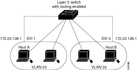
Devices within a single VLAN can communicate directly through any switch. Ports in different VLANs cannot exchange data without going through a routing device. With a standard Layer 2 device, ports in different VLANs have to exchange information through a router. By using the device with routing enabled, when you configure both VLAN 20 and VLAN 30 with an SVI to which an IP address is assigned, packets can be sent from Host A to Host B directly through the device with no need for an external router.

Figure 1. Connecting VLANs with the Switch

When the Network Advantage license is used on the device or the active device, the device uses the routing method to forward traffic between interfaces. If the Network Essentials license is used on the device or the active device, only basic routing (static routing and RIP) is supported. Whenever possible, to maintain high performance, forwarding is done by the device hardware. However, only IPv4 packets with Ethernet II encapsulation are routed in hardware.

The routing function can be enabled on all SVIs and routed ports. The device routes only IP traffic. When IP routing protocol parameters and address configuration are added to an SVI or routed port, any IP traffic received from these ports is routed.

Interface Configuration Mode

The device supports these interface types:

  • Physical ports: Device ports and routed ports

  • VLANs: Switch virtual interfaces

  • Port channels: EtherChannel interfaces

You can also configure a range of interfaces.

An interface on the device is represented by a 3-tuple notation that lists the module, subslot, and port.

To configure a physical interface (port), specify the interface type, module number, sub-slot number, and device port number, and enter interface configuration mode.

  • Type: 25-Gigabit Ethernet (TwentyFiveGigE or twe) for 25 Gbps, 40-Gigabit Ethernet (FortyGigabitEthernet or fo) for 40 Gbps, and 100-Gigabit Ethernet (HundredGigE or hu) for 100Gbps.

  • Module number: The module or slot number on the device.

  • Subslot number: The subslot number is always 0.

  • Port number: The interface number on the device. The port numbering starts with the far left port when facing the front of the device, for example, FortyGigabitEthernet1/0/1.

You can identify physical interfaces by physically checking the interface location on the device. You can also use the show privileged EXEC commands to display information about a specific interface or all the interfaces on the switch. The remainder of this chapter primarily provides physical interface configuration procedures.

    Default Ethernet Interface Configuration

    To configure Layer 2 parameters, if the interface is in Layer 3 mode, you must enter the switchport interface configuration command without any parameters to put the interface into Layer 2 mode. This shuts down the interface and then re-enables it, which might generate messages on the device to which the interface is connected. When you put an interface that is in Layer 3 mode into Layer 2 mode, the previous configuration information related to the affected interface might be lost, and the interface is returned to its default configuration.


    Note


    The interface is in Layer 3 by default.


    This table shows the Ethernet interface default configuration, including some features that apply only to Layer 2 interfaces.

    Table 1. Default Layer 2 Ethernet Interface Configuration

    Feature

    Default Setting

    Operating mode

    Layer 3 or routed port.

    Allowed VLAN range

    VLANs 1– 4094.

    Default VLAN (for access ports)

    VLAN 1 (Layer 2 interfaces only).

    Native VLAN (for IEEE 802.1Q trunks)

    VLAN 1 (Layer 2 interfaces only).

    VLAN trunking

    Switchport mode dynamic auto (supports DTP) (Layer 2 interfaces only).

    Port enable state

    All ports are enabled.

    Port description

    None defined.

    Speed

    Speed is determined by the type of transceiver module plugged in.

    Duplex mode

    Full Duplex mode supported.

    Flow control

    Flow control is set to receive: off . It is always off for sent packets.

    EtherChannel (PAgP)

    Disabled on all Ethernet ports.

    Port blocking (unknown multicast and unknown unicast traffic)

    Disabled (not blocked) (Layer 2 interfaces only).

    Broadcast, multicast, and unicast storm control

    Disabled.

    Protected port

    Disabled (Layer 2 interfaces only).

    Port security

    Disabled (Layer 2 interfaces only).

    Port Fast

    Disabled.

    Auto-MDIX

    Enabled.

    Interface Speed and Duplex Mode

    Switch modules include SFP modules that support speeds up to 1 Gbps, SFP+ modules that support speeds up to 10 Gbps, SFP28 modules that support speeds up to 25 Gbps, QSFP modules that support speeds up to 40 Gbps and 100 Gbps.

    The ethernet interfaces operate at full duplex mode. In full-duplex mode, two stations can send and receive traffic at the same time.

    Port Mapping and Oversubscription

    The Catalyst 9600 modular chassis supports up to four line cards and redundant supervisors. The supervisor has three Unified Access Data Path (UADP 3.0) ASICs connected to each other. Each UADP 3.0 ASIC provides a switching capacity of 1600Gbps full-duplex for the front panel interfaces, resulting in a total capacity of 4800 Gbps full-duplex switching capacity.

    Figure 2. Three ASIC Configuration

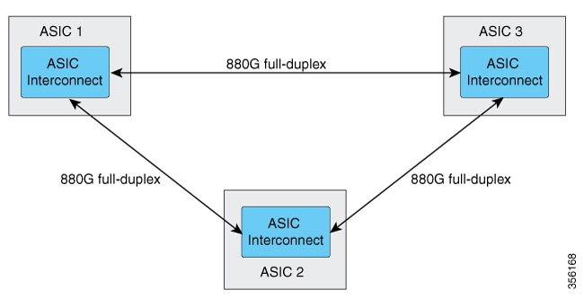
    Each ASIC also provides a total of 1760 Gbps full-duplex inter-ASIC bandwidth, with 880 Gbps full-duplex to each of the other two ASICs.

    The inter-ASIC connections use a broadcast network approach, to ensure that user data is available to all ASICs. In the worst-case scenario, where all traffic is inter-ASIC, the front panel bandwidth can be 2:1 oversubscribed compared to the interface-ASIC bandwidth. Most traffic scenarios (example north-to-south) will only require some traffic to be inter-ASIC.

    When a Line card is installed on the chassis, one-third of its ports are connected to each ASIC. Which means, one set of ports on the line card are connected to ASIC 1, the second set to ASIC 2, and the third set of ports are connected to ASIC 3. You can view the port mapping on the line cards using the show platform software fed active ifm mapping command.

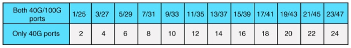
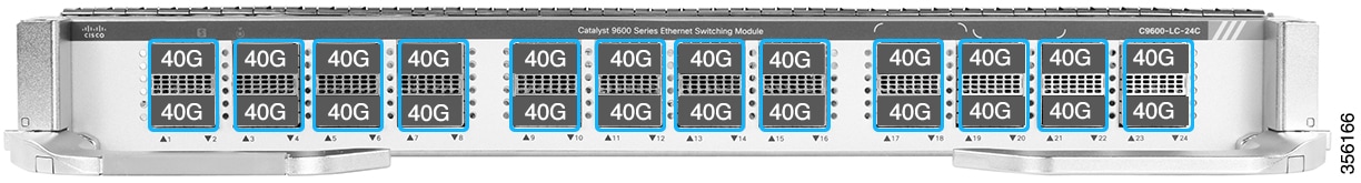
    Port Mapping on C9600-LC-24C

    By default, all the interfaces on a C9600-LC-24C line card are 40 G or 1 G enabled. You can configure the odd-numbered 40 G or 1 G interface to function as 100 G port using the enable command on the interface. In such a case, the corresponding even-numbered port in the port group is disabled. (A port group constitutes the top and bottom consecutive ports.)

    Figure 3. Port Numbering on C9600-LC-24C
    Figure 4. Default Configuration on C9600-LC-24C
    Figure 5. 100 G Configuration on C9600-LC-24C

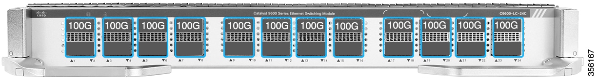
    C9600-LC-24C supports CVR-QSFP-SFP10G (QSA adapter) that provides 10 G connectivity on QSFP ports by converting a 40 G or 100 G QSFP port into an SFP/SFP+ port.

    C9600-LC-24C supports only the following port group configurations with CVR-QSFP-SFP10G:

    • Configuring odd-numbered (top) and even-numbered (bottom) ports with the QSA adapter

    • Configuring odd-numbered ports with the QSA adapter and even-numbered ports with 40 G QSFP optics


    Note


    In a port group, if you configure the odd-numbered port with 40 G QSFP optics and the even-numbered port with the QSA adapter, the QSA adapter in the even-numbered port doesn’t work.


    IEEE 802.3x Flow Control

    Flow control enables connected Ethernet ports to control traffic rates during congestion by allowing congested nodes to pause link operation at the other end. If one port experiences congestion and cannot receive any more traffic, it notifies the other port by sending a pause frame to stop sending until the condition clears. Upon receipt of a pause frame, the sending device stops sending any data packets, which prevents any loss of data packets during the congestion period.


    Note


    The switch ports can receive, but not send, pause frames.


    You use the flowcontrol interface configuration command to set the interface’s ability to receive pause frames to on, off, or desired. The default state is on.

    When set to desired, an interface can operate with an attached device that is required to send flow-control packets or with an attached device that is not required to but can send flow-control packets.

    These rules apply to flow control settings on the device:

    • receive on (or desired ): The port cannot send pause frames but can operate with an attached device that is required to or can send pause frames; the port can receive pause frames.

    • receive off : Flow control does not operate in either direction. In case of congestion, no indication is given to the link partner, and no pause frames are sent or received by either device.


    Note


    For details on the command settings and the resulting flow control resolution on local and remote ports, see the flowcontrol interface configuration command in the command reference for this release.


    Layer 3 Interfaces

    The device supports these types of Layer 3 interfaces:

    • SVIs: You should configure SVIs for any VLANs for which you want to route traffic. SVIs are created when you enter a VLAN ID following the interface vlan global configuration command. To delete an SVI, use the no interface vlan global configuration command. You cannot delete interface VLAN 1.


      Note


      When you create an SVI, it does not become active until it is associated with a physical port.


      When configuring SVIs, you can use the switchport autostate exclude command on a port to exclude that port from being included in determining SVI line-state. To disable autostate on the SVI, use the no autostate command on the SVI.

    • Routed ports: Routed ports are physical ports configured to be in Layer 3 mode by using the no switchport interface configuration command.

    • Layer 3 EtherChannel ports: EtherChannel interfaces made up of routed ports.

    A Layer 3 device can have an IP address assigned to each routed port and SVI.

    There is no defined limit to the number of SVIs and routed ports that can be configured in a device or in a device stack. However, the interrelationship between the number of SVIs and routed ports and the number of other features being configured might have an impact on CPU usage because of hardware limitations. If the device is using its maximum hardware resources, attempts to create a routed port or SVI have these results:

    • If you try to create a new routed port, the device generates a message that there are not enough resources to convert the interface to a routed port, and the interface remains as a switchport.

    • If you try to create an extended-range VLAN, an error message is generated, and the extended-range VLAN is rejected.

    • If the device is notified by VLAN Trunking Protocol (VTP) of a new VLAN, it sends a message that there are not enough hardware resources available and shuts down the VLAN. The output of the show vlan user EXEC command shows the VLAN in a suspended state.

    • If the device attempts to boot up with a configuration that has more VLANs and routed ports than hardware can support, the VLANs are created, but the routed ports are shut down, and the device sends a message that this was due to insufficient hardware resources.


    Note


    All Layer 3 interfaces require an IP address to route traffic. This procedure shows how to configure an interface as a Layer 3 interface and how to assign an IP address to an interface:

    If the physical port is in Layer 2 mode (the default), you must enter the no switchport interface configuration command to put the interface into Layer 3 mode. Entering a no switchport command disables and then re-enables the interface, which might generate messages on the device to which the interface is connected. Furthermore, when you put an interface that is in Layer 2 mode into Layer 3 mode, the previous configuration information related to the affected interface might be lost, and the interface is returned to its default configuration


    How to Configure Interface Characteristics

    Configuring Interfaces

    These general instructions apply to all interface configuration processes.

    Procedure

      Command or Action Purpose

    Step 1

    enable

    Example:

    Device> enable

    Enables privileged EXEC mode.

    Enter your password, if prompted.

    Step 2

    configure terminal

    Example:

    
    Device# configure terminal


    Enters global configuration mode.

    Step 3

    interface

    Example:

    
    Device(config)# interface fortygigabitethernet1/0/1
    Device(config-if)# 


    Identifies the interface type, and the number of the connector.

    Note


    You do not need to add a space between the interface type and the interface number. For example, in the preceding line, you can specify either fortygigabitethernet 1/0/1 , or fortygigabitethernet1/0/1 .

    Step 4

    Follow each interface command with the interface configuration commands that the interface requires.

    Defines the protocols and applications that will run on the interface. The commands are collected and applied to the interface when you enter another interface command or enter end to return to privileged EXEC mode.

    Step 5

    interface range or interface range macro

    (Optional) Configures a range of interfaces.

    Note


    Interfaces configured in a range must be the same type and must be configured with the same feature options.

    Step 6

    show interfaces

    Displays a list of all interfaces on or configured for the switch. A report is provided for each interface that the device supports or for the specified interface.

    Adding a Description for an Interface

    Procedure

      Command or Action Purpose

    Step 1

    enable

    Example:

    
    Device> enable


    Enables privileged EXEC mode.

    • Enter your password if prompted.

    Step 2

    configure terminal

    Example:

    
    Device# configure terminal


    Enters global configuration mode.

    Step 3

    interface interface-id

    Example:

    Device(config)# interface fortygigabitethernet1/0/2

    Specifies the interface for which you are adding a description, and enter interface configuration mode.

    Step 4

    description string

    Example:

    
    Device(config-if)# description Connects to Marketing


    Adds a description for an interface.

    Step 5

    end

    Example:

    
    Device(config-if)# end


    Returns to privileged EXEC mode.

    Step 6

    show interfaces interface-id description

    Verifies your entry.

    Step 7

    copy running-config startup-config

    Example:

    
    Device# copy running-config startup-config 


    (Optional) Saves your entries in the configuration file.

    Configuring a Range of Interfaces

    To configure multiple interfaces with the same configuration parameters, use the interface range global configuration command. When you enter the interface-range configuration mode, all command parameters that you enter are attributed to all interfaces within that range until you exit this mode.

    Procedure

      Command or Action Purpose

    Step 1

    enable

    Example:

    
    Device> enable


    Enables privileged EXEC mode.

    Enter your password, if prompted.

    Step 2

    configure terminal

    Example:

    
    Device# configure terminal


    Enters global configuration mode.

    Step 3

    interface range {port-range | macro macro_name}

    Example:

    
    Device(config)# interface range macro


    Specifies the range of interfaces (VLANs or physical ports) to be configured, and enter interface-range configuration mode.

    • You can use the interface range command to configure up to five port ranges or a previously defined macro.

    • The macro variable is explained in Configuring and Using Interface Range Macros.

    • In a comma-separated port-range , you must enter the interface type for each entry and enter spaces before and after the comma.

    • In a hyphen-separated port-range , you do not need to re-enter the interface type, but you must enter a space before the hyphen.

    Note


    Use the normal configuration commands to apply the configuration parameters to all interfaces in the range. Each command is executed as it is entered.

    Step 4

    end

    Example:

    
    Device(config)# end


    Returns to privileged EXEC mode.

    Step 5

    show interfaces [interface-id]

    Example:

    
    Device# show interfaces


    Verifies the configuration of the interfaces in the range.

    Step 6

    copy running-config startup-config

    Example:

    
    Device# copy running-config startup-config 


    (Optional) Saves your entries in the configuration file.

    Configuring and Using Interface Range Macros

    You can create an interface range macro to automatically select a range of interfaces for configuration. Before you can use the macro keyword in the interface range macro global configuration command string, you must use the define interface-range global configuration command to define the macro.

    Procedure

      Command or Action Purpose

    Step 1

    enable

    Example:

    
    Device> enable


    Enables privileged EXEC mode.

    Enter your password, if prompted.

    Step 2

    configure terminal

    Example:

    
    Device# configure terminal


    Enters global configuration mode.

    Step 3

    define interface-range macro_name interface-range

    Example:

    Defines the interface-range macro, and saves it in NVRAM.

    • The macro_name is a 32-character maximum character string.

    • A macro can contain up to five comma-separated interface ranges.

    • Each interface-range must consist of the same port type.

    Note


    Before you can use the macro keyword in the interface range macro global configuration command string, you must use the define interface-range global configuration command to define the macro.

    Step 4

    interface range macro macro_name

    Example:

    
    Device(config)# interface range macro enet_list


    Selects the interface range to be configured using the values saved in the interface-range macro called macro_name .

    You can now use the normal configuration commands to apply the configuration to all interfaces in the defined macro.

    Step 5

    end

    Example:

    
    (config)# end


    Returns to privileged EXEC mode.

    Step 6

    show running-config | include define

    Example:

    
    Device# show running-config | include define


    Shows the defined interface range macro configuration.

    Step 7

    copy running-config startup-config

    Example:

    
    Device# copy running-config startup-config 


    (Optional) Saves your entries in the configuration file.

    Configuring Hundred Gigabit Ethernet Interface on C9600-LC-24C

    By default, 40G is enabled on all ports of C9600-LC-24C linecard. You can enable 100 G on the odd-numbered ports (ports 25, 27, 29, 31, 33, 35, 37, 39, 41, 43, 45, and 47) of the linecard. When 100 G is enabled, 40 G is disabled on the corresponding port and the port below it.

    Follow these steps to enable 100 G on the ports:

    Procedure

      Command or Action Purpose

    Step 1

    enable

    Example:

    Device> enable

    Enables privileged EXEC mode.

    • Enter your password if prompted.

    Step 2

    configure terminal

    Example:

    Device# configure terminal

    Enters global configuration mode.

    Step 3

    interface interface-type interface-id

    Example:

    Device(config)# interface HundredGigabitEthernet1/0/27

    Specifies the interface that is to be configured.

    Step 4

    enable

    Example:

    Device(config-if)# enable

    Enables the hundred gigabit ethernet interface. Use no enable command to disable the hundred gigabit ethernet interface.

    Configuring IEEE 802.3x Flow Control

    Procedure

      Command or Action Purpose

    Step 1

    configure terminal

    Example:

    
    Device# configure terminal


    Enters global configuration mode

    Step 2

    interface interface-id

    Example:

    
    Device(config)# interface fortygigabitethernet1/0/1


    Specifies the physical interface to be configured, and enters interface configuration mode.

    Step 3

    flowcontrol {receive} {on | off | desired}

    Example:

    
    Device(config-if)# flowcontrol receive on


    Configures the flow control mode for the port.

    Step 4

    end

    Example:

    
    Device(config-if)# end


    Returns to privileged EXEC mode.

    Step 5

    show interfaces interface-id

    Example:

    
    Device# show interfaces fortygigabitethernet1/0/1


    Verifies the interface flow control settings.

    Step 6

    copy running-config startup-config

    Example:

    
    Device# copy running-config startup-config 


    (Optional) Saves your entries in the configuration file.

    Configuring Layer 3 Interfaces

    Procedure

      Command or Action Purpose

    Step 1

    enable

    Example:

    
    Device> enable


    Enables privileged EXEC mode.

    Enter your password, if prompted.

    Step 2

    configure terminal

    Example:

    
    Device# configure terminal


    Enters global configuration mode.

    Step 3

    interface {fortygigabitethernet interface-id} | {vlan vlan-id} | {port-channel port-channel-number}

    Example:

    
    Device(config)# interface fortygigabitethernet1/0/2


    Specifies the interface to be configured as a Layer 3 interface, and enters interface configuration mode.

    Step 4

    no switchport

    Example:

    
    Device(config-if)# no switchport


    (For physical ports only) Enters Layer 3 mode.

    Step 5

    ip address ip_address subnet_mask

    Example:

    
    Device(config-if)# ip address 192.20.135.21 255.255.255.0


    Configures the IP address and IP subnet.

    Step 6

    no shutdown

    Example:

    
    Device(config-if)# no shutdown


    Enables the interface.

    Step 7

    end

    Example:

    
    Device(config-if)# end


    Returns to privileged EXEC mode.

    Step 8

    show interfaces [interface-id]

    Verifies the configuration.

    Step 9

    copy running-config startup-config

    Example:

    
    Device# copy running-config startup-config 


    (Optional) Saves your entries in the configuration file.

    Configuring a Logical Layer 3 GRE Tunnel Interface

    Before you begin

    Generic Routing Encapsulation (GRE) is a tunneling protocol used to encapsulate network layer protocols inside virtual point-to-point links. A GRE tunnel only provides encapsulation and not encryption.


    Note


    • GRE tunnels are supported on the hardware on Cisco Catalyst 9000 switches. When GRE is configured without tunnel options, packets are hardware-switched. When GRE is configured with tunnel options (such as key, checksum, and so on), packets are switched in the software. A maximum of 900 GRE tunnels are supported.

    • Other features such as Access Control Lists (ACL) and Quality of Service (QoS) are not supported for the GRE tunnels.

    • The tunnel path-mtu-discovery command is not supported for GRE tunnels. To avoid fragmentation, you can set the maximum transmission unit (MTU) of both ends of the GRE tunnel to the lowest value by using the ip mtu 256 command.


    To configure a GRE tunnel, perform this task:

    Procedure

      Command or Action Purpose

    Step 1

    enable

    Example:

    
    Device> enable


    Enables privileged EXEC mode.

    Enter your password, if prompted.

    Step 2

    configure terminal

    Example:

    
    Device# configure terminal


    Enters global configuration mode.

    Step 3

    interface tunnel number

    Example:

    Device(config)#interface tunnel 2

    Enables tunneling on the interface.

    Step 4

    ip address ip_addresssubnet_mask

    Example:

    Device(config)#ip address 100.1.1.1 255.255.255.0

    Configures the IP address and IP subnet.

    Step 5

    tunnel source {ip_address | type_number}

    Example:

    Device(config)#tunnel source 10.10.10.1

    Configures the tunnel source.

    Step 6

    tunnel destination {host_name | ip_address}

    Example:

    Device(config)#tunnel destination 10.10.10.2

    Configures the tunnel destination.

    Step 7

    tunnel mode gre ip

    Example:

    Device(config)#tunnel mode gre ip

    Configures the tunnel mode.

    Step 8

    end

    Example:

    Device(config)#end

    Exits configuration mode.

    Configuring SVI Autostate Exclude

    Procedure

      Command or Action Purpose

    Step 1

    enable

    Example:

    
    Device> enable


    Enables privileged EXEC mode.

    Enter your password, if prompted.

    Step 2

    configure terminal

    Example:

    
    Device# configure terminal


    Enters global configuration mode.

    Step 3

    interface interface-id

    Example:

    
    Device(config)# interface fortygigabitethernet1/0/2


    Specifies a Layer 2 interface (physical port or port channel), and enters interface configuration mode.

    Step 4

    switchport autostate exclude

    Example:

    
    Device(config-if)# switchport autostate exclude


    Excludes the access or trunk port when defining the status of an SVI line state (up or down)

    Step 5

    end

    Example:

    
    Device(config-if)# end


    Returns to privileged EXEC mode.

    Step 6

    show running config interface interface-id

    (Optional) Shows the running configuration.

    Verifies the configuration.

    Step 7

    copy running-config startup-config

    Example:

    
    Device# copy running-config startup-config 


    (Optional) Saves your entries in the configuration file.

    Shutting Down and Restarting the Interface

    Shutting down an interface disables all functions on the specified interface and marks the interface as unavailable on all monitoring command displays. This information is communicated to other network servers through all dynamic routing protocols. The interface is not mentioned in any routing updates.

    Procedure

      Command or Action Purpose

    Step 1

    enable

    Example:

    
    Device> enable


    Enables privileged EXEC mode.

    Enter your password, if prompted.

    Step 2

    configure terminal

    Example:

    
    Device# configure terminal


    Enters global configuration mode.

    Step 3

    interface {vlan vlan-id} | { fortygigabitethernet interface-id} | {port-channel port-channel-number}

    Example:

    
    Device(config)# interface fortygigabitethernet1/0/2


    Selects the interface to be configured.

    Step 4

    shutdown

    Example:

    
    Device(config-if)# shutdown


    Shuts down an interface.

    Step 5

    no shutdown

    Example:

    
    Device(config-if)# no shutdown


    Restarts an interface.

    Step 6

    end

    Example:

    
    Device(config-if)# end


    Returns to privileged EXEC mode.

    Step 7

    show running-config

    Example:

    
    Device# show running-config 


    Verifies your entries.

    Configuring the Console Media Type

    Follow these steps to set the console media type to RJ-45. If you configure the console as RJ-45, USB console operation is disabled, and input comes only through the RJ-45 connector.

    Procedure

      Command or Action Purpose

    Step 1

    enable

    Example:

    
    Device> enable


    Enables privileged EXEC mode.

    Enter your password, if prompted.

    Step 2

    configure terminal

    Example:

    
    Device# configure terminal


    Enters global configuration mode.

    Step 3

    line console 0

    Example:

    
    Device(config)# line console 0


    Configures the console and enters line configuration mode.

    Step 4

    media-type rj45 switch switch_number

    Example:

    
    Device(config-line)# media-type rj45 switch 1


    Configures the console media type to be only RJ-45 port. If you do not enter this command and both types are connected, the USB port is used by default.

    Step 5

    end

    Example:

    
    Device(config)# end


    Returns to privileged EXEC mode.

    Step 6

    copy running-config startup-config

    Example:

    
    Device# copy running-config startup-config 


    (Optional) Saves your entries in the configuration file.

    Configuring USB Inactivity Timeout

    The configurable inactivity timeout reactivates the RJ-45 console port if the USB console port is activated but no input activity occurs on it for a specified time period. When the USB console port is deactivated due to a timeout, you can restore its operation by disconnecting and reconnecting the USB cable.

    Procedure

      Command or Action Purpose

    Step 1

    enable

    Example:

    
    Device> enable


    Enables privileged EXEC mode.

    Enter your password, if prompted.

    Step 2

    configure terminal

    Example:

    
    Device# configure terminal


    Enters global configuration mode.

    Step 3

    line console 0

    Example:

    
    Device(config)# line console 0


    Configures the console and enters line configuration mode.

    Step 4

    usb-inactivity-timeout switch switch_number timeout-minutes

    Example:

    
    Device(config-line)# usb-inactivity-timeout switch 1 30 


    Specifies an inactivity timeout for the console port. The range is 1 to 240 minutes. The default is to have no timeout configured.

    Step 5

    copy running-config startup-config

    Example:

    
    Device# copy running-config startup-config 


    (Optional) Saves your entries in the configuration file.

    Monitoring Interface Characteristics

    Monitoring Interface Status

    Commands entered at the privileged EXEC prompt display information about the interface, including the versions of the software and the hardware, the configuration, and statistics about the interfaces.

    Table 2. show Commands for Interfaces

    Command

    Purpose

    show interfaces interface-id status [err-disabled]

    Displays interface status or a list of interfaces in the error-disabled state.

    show interfaces [interface-id] switchport

    Displays administrative and operational status of switching (nonrouting) ports. You can use this command to find out if a port is in routing or in switching mode.

    show interfaces [interface-id] description

    Displays the description configured on an interface or all interfaces and the interface status.

    show ip interface [interface-id]

    Displays the usability status of all interfaces configured for IP routing or the specified interface.

    show interface [interface-id] stats

    Displays the input and output packets by the switching path for the interface.

    show interfaces interface-id

    (Optional) Displays speed and duplex on the interface.

    show interfaces transceiver dom-supported-list

    (Optional) Displays Digital Optical Monitoring (DOM) status on the connect SFP modules.

    show interfaces transceiver properties

    (Optional) Displays temperature, voltage, or amount of current on the interface.

    show interfaces [interface-id] [{transceiver properties | detail}] module number]

    Displays physical and operational status about an SFP module.

    show running-config interface [interface-id]

    Displays the running configuration in RAM for the interface.

    show version

    Displays the hardware configuration, software version, the names and sources of configuration files, and the boot images.

    show controllers ethernet-controller interface-id phy

    Displays the operational state of the auto-MDIX feature on the interface.

    Clearing and Resetting Interfaces and Counters

    Table 3. clear Commands for Interfaces

    Command

    Purpose

    clear counters [interface-id]

    Clears interface counters.

    clear interface interface-id

    Resets the hardware logic on an interface.

    clear line [number | console 0 | vty number]

    Resets the hardware logic on an asynchronous serial line.


    Note


    The clear counters privileged EXEC command does not clear counters retrieved by using Simple Network Management Protocol (SNMP), but only those seen with the show interface privileged EXEC command.


    Configuration Examples for Interface Characteristics

    The following sections provide examples of interface characteristics configurations.

    Example: Adding a Description to an Interface

    The following example shows how to add a description to an interface:

    
    Device# configure terminal
    Enter configuration commands, one per line. End with CNTRL/Z.
    Device(config)# interface fortygigabitethernet1/0/2
    Device(config-if)# description Connects to Marketing
    Device(config-if)# end
    Device# show interfaces fortygigabitethernet1/0/2 description
    Interface Status    Protocol Description
    Fo1/0/1   down      down      Connects to Marketing


    Example: Configuring a Range of Interfaces

    
    Device# configure terminal
    Device(config)# interface range fortyGigabitEthernet 1/0/1-2
     
    Device(config-if-range)# shut


    If you enter multiple configuration commands while you are in interface-range mode, each command is executed as it is entered. The commands are not batched and executed after you exit interface-range mode. If you exit interface-range configuration mode while the commands are being executed, some commands might not be executed on all interfaces in the range. Wait until the command prompt reappears before exiting interface-range configuration mode.

    Example: Configuring and Using Interface Range Macros

    The following example shows how to enter interface-range configuration mode for the interface-range macro enet_list:

    
    Device# configure terminal
    Device(config)# interface range macro enet_list
    Device(config-if-range)# 


    The following example shows how to delete the interface-range macro enet_list and to verify that it was deleted.

    
    Device# configure terminal
    Device(config)# no define interface-range enet_list 
    Device(config)# end
    Device# show run | include define
    Device# 


    Example: Configuring Layer 3 Interfaces

    The following example shows how to configure layer 3 interfaces:

    
    Device# configure terminal
    Enter configuration commands, one per line.  End with CNTL/Z.
    Device(config)# interface fortygigabitethernet1/0/2
    Device(config-if)# no switchport
    Device(config-if)# ip address 192.20.135.21 255.255.255.0
    Device(config-if)# no shutdown


    Example: Configuring the USB Inactivity Timeout

    The following example shows how to configure the inactivity timeout to 30 minutes:

    
    Device# configure terminal
    Device(config)# line console 0
    Device(config-line)# usb-inactivity-timeout switch 1 30 


    The following example shows how to disable the configuration:

    
    Device# configure terminal
    Device(config)# line console 0
    Device(config-line)# no usb-inactivity-timeout switch 1


    If there is no (input) activity on a USB console port for the configured number of minutes, the inactivity timeout setting applies to the RJ-45 port, and a log shows this occurrence:

    
    *Mar  1 00:47:25.625: %USB_CONSOLE-6-INACTIVITY_DISABLE: Console media-type USB disabled due to inactivity, media-type reverted to RJ45.
    

    At this point, the only way to reactivate the USB console port is to disconnect and reconnect the cable.

    When the USB cable on the switch has been disconnected and reconnected, a log similar to this appears:

    
    *Mar  1 00:48:28.640: %USB_CONSOLE-6-MEDIA_USB: Console media-type is USB.
    

    Additional References for Interface Characteristics

    Related Documents

    Related Topic Document Title

    For complete syntax and usage information for the commands used in this chapter.

    See the Interface and Hardware Commands section in the Command Reference (Catalyst 9600 Series Switches) .

    Feature History for Configuring Interface Characteristics

    This table provides release and related information for the features explained in this module.

    These features are available in all the releases subsequent to the one they were introduced in, unless noted otherwise.

    Release

    Feature

    Feature Information

    Cisco IOS XE Gibraltar 16.11.1

    Interface Characteristics

    Interface Characteristics includes interface types, connections, configuration modes, speed, and other aspects of configuring a physical interface on a device.

    Use the Cisco Feature Navigator to find information about platform and software image support. To access Cisco Feature Navigator, go to http://www.cisco.com/go/cfn.