Installing the Fan Tray

Guidelines for Removing and Installing a Fan Tray

Before removing or installing a fan tray ensure you read and follow the guidelines and safety warnings listed here.
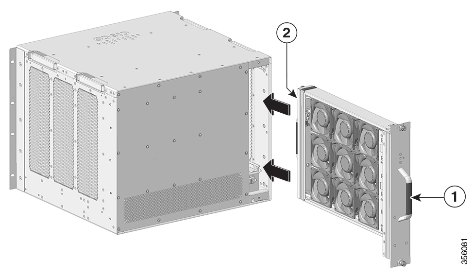

Caution


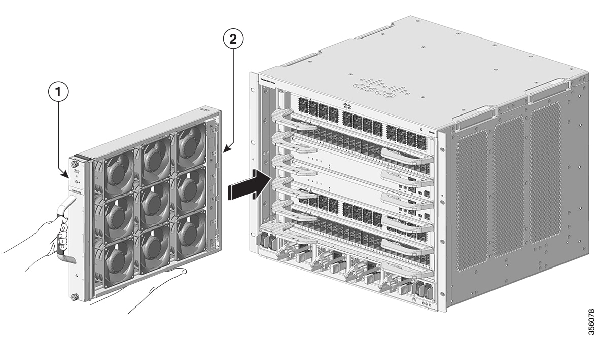
When removing the fan tray, keep your hands and fingers away from the spinning fan blades. Let the fan blades completely stop before you remove the fan tray.

Removing a Fan Tray

The following sections explain the steps to remove a fan tray in a Cisco Catalyst 9600 Series switches.

Information About Replacing a Fan Tray

Online Insertion and Removal

While the fan tray is designed to be removed and installed while the system is operating (powered on) without presenting an electrical hazard or damage to the system, there is a time constraint when you remove and replace the fan tray in a system that is powered on.


Caution


The system can safely run without a fan tray only for a few minutes, until the critical temperature threshold is exceeded. Watch for any alarms triggered in software. After the critical temperature threshold is exceeded without sufficient cooling, the system shuts down if the alarm is not cleared.


When the fan tray is removed and replaced in a non-operating system, there is no time constraint.

Following the Correct Removal and Replacement Procedure

When you order a spare, only the fan tray is shipped. The connector is not shipped with a spare and you have to use the one originally available with the fan tray assembly.

You can remove and replace the fan tray from the front or the rear. When removed from the front of the chassis, only the fan tray is removed. When removed from the rear, the entire fan tray assembly (including the connector) is removed.

Removal and replacement from the front is suited to situations where access to the rear of the system is restricted. For instance, where the installation is in a closet. Removal and replacement from the rear is suited to situations where input and output cables are routed across the front panel, limiting access to the front panel of the fan tray.

Follow the corresponding removal and replacement procedures.

Enabling the Service Mode Before Removing the Fan Tray

This task describes how to enable the service mode before removing the fan tray from a chassis. Enabling the service mode pushes the fans to operate at full speed and cool down the system sufficiently, allowing the system to sustain temperatures for the duration of servicing.

In a system that is operational, this applies to removal or replacement procedures from the front and the rear. You do not have to enable this mode if you are removing and replacing the fan tray in a system that is not powered on.

For standalone configuration, enter this command in privileged EXEC mode.


Device# test platform hardware chassis fantray service-mode on
fantray service mode on
If your system is part of a StackWise Virtual configuration, select the chassis where the service mode should be enabled.

Device# test platform hardware chassis fantray service-mode on switch {active | standby}
fantray service mode on

The system automatically turns off the service mode after 10 minutes. This cools down the chassis sufficiently for the service duration.

To turn off the service mode before this system-allotted duration for a standalone configuration, enter this command.


Device#test platform hardware chassis fantray service-mode off
fantray service mode off
To turn off the service mode before the system-allocated duration for an StackWise Virtual configuration, enter this command.
Device#test platform hardware chassis fantray service-mode off switch <active/standby>
fantray service mode off 

Removing the Fan Tray from the Front of the Chassis

Before you begin

  • Read Guidelines for Removing and Installing a Fan Tray.

  • Enable the service mode on the chassis, if you are performing this task in a system that is powered on.

  • Ensure that you have the following tools and accessories available:

    • Phillips-head screwdriver

    • Anti-static mat

Procedure


Step 1

Keep the replacement fan tray ready for installation.

Important


When you remove and replace the fan tray in a system that is powered on, there is a time constraint. The system can safely run without a fan tray only for 2 minutes. So, it is important to complete this first step and its sub-steps before you remove the fan tray from the front of the chassis.

  1. Remove the replacement fan tray from the shipping packaging.

  2. Use the Phillips-head screwdriver and loosen the two captive installation screws on the front panel of the replacement fan tray (the side with the fan STATUS LED), to detach it from the connector.

    Figure 1. Detaching the Connector from the Fan Tray


    1

    Captive installation screws on the front of the fan tray assembly

    3

    Fan tray

    2

    The connector in the rear, separated from the fan tray

    -

    -

    The connector is not used or replaced when installed from the front. The connector can be scrapped or stored for future use.

  3. Place the replacement fan tray on an anti-static mat and within arm's reach.

Step 2

Proceed with removing the fan tray from the chassis. Loosen the two captive installation screws on the front panel of the fan tray (the side with the fan STATUS LED).

Figure 2. Removing the Captive Installation Screws


1

Captive installation screws on the front of the fan tray assembly in the chassis

Step 3

Grasp the fan tray handle and slide the fan tray half-way out of the bay. Gently move it from side to side, if necessary, to unseat it from the backplane.

Step 4

Wait for the fan blades to stop spinning; place your other hand underneath to support the bottom of the fan tray and then remove the fan tray completely.

Only the fan tray is removed from the chassis (excluding the connector).


What to do next

Set the removed fan tray aside and proceed with installing the replacement or spare fan tray.

Removing the Fan Tray from the Rear of the Chassis

When you remove the fan tray from the rear, the fan tray assembly is removed. This includes the fan tray and the connector.

Before you begin

  • Read Guidelines for Removing and Installing a Fan Tray.

  • Enable the service mode on the chassis, if you are performing this task in a system that is powered on.

  • Ensure that you have the following tools and accessories available:

    • Phillips-head screwdriver

    • Anti-static mat

Procedure


Step 1

Keep the replacement fan tray ready by removing it from the shipping packaging. Place it on an anti-static mat and within arm's reach. Do not detach the connector module.

Important


When you remove and replace the fan tray in a system that is powered on, there is a time constraint. The system can safely run without a fan tray only for 2 minutes. So it is important to complete this first step before you remove the fan tray from the rear of the chassis.

Figure 3. Fan Tray with the Connector


1

Fan tray with the connector

Step 2

Proceed with removing the fan tray from the chassis. Loosen the two captive installation screws on the rear panel of the fan tray.

Figure 4. Captive Installation Screws on the Rear Panel


1

Rear fan tray handle

2

Captive installation screws on the rear panel.

Note


Loosen to uninstall the fan tray assembly from the rear.

Step 3

Grasp the fan tray handle and slide the fan tray assembly half-way out of the bay.

Step 4

Wait for the fan blades to stop spinning; place your other hand underneath to support the bottom of the fan tray and then remove the fan tray assembly completely.


What to do next

Set the removed fan tray aside and proceed with installing the replacement or spare fan tray.

Installing a Fan Tray

The following sections provide information about installing a fan tray in Cisco Catalyst 9600 Series switches.

Installing the Fan Tray from the Front Panel of the Chassis

Before you begin

  • Read Guidelines for Removing and Installing a Fan Tray.

  • Enable the service mode on the chassis, if you are performing this task in a system that is powered on.

  • Ensure that you have the following tools and accessories available:

    • Phillips-head screwdriver

    • Anti-static mat

Procedure


Step 1

Hold the fan tray assembly with the fans facing to the right.

Step 2

Place the fan tray into the fan tray slot so it rests on the chassis, and then lift the fan tray up slightly, aligning the top and bottom guides.

Figure 5. Inserting the Fan Tray from the Front of the Chassis


1

Front side of the fan tray

2

Fan tray without the connector

Step 3

Slide the fan tray into the chassis until the two captive installation screws make contact with the chassis.

Step 4

Tighten the two captive installation screws on the front, to secure the fan tray assembly in the chassis.


What to do next

Verify that you have installed the fan tray correctly. See Verifying Fan Tray Installation.

Installing the Fan Tray from the Rear of the Chassis

Before you begin

  • Read Guidelines for Removing and Installing a Fan Tray.

  • Enable the service mode on the chassis, if you are performing this task in a system that is powered on.

  • Ensure that you have the following tools and accessories available:

    • Phillips-head screwdriver

    • Anti-static mat

Procedure


Step 1

On the replacement fan tray assembly, ensure that the two screws securing the fantray to the connector (on the side with the fan STATUS LEDs) are tight. Be careful not to overtighten the screws.

Step 2

Hold the fan tray assembly such that the side with the STATUS LED is inserted first.

Figure 6. Inserting the Fan Tray from the Rear of the Chassis


1

Release handle on the front of the fan tray.

Note


Ensure that the captive installation screws on this side are tightened before sliding the fan tray in.

2

Rear panel of the fan tray.

Note


Tighten the captive installation screws on this side, after sliding the fan tray in.

Step 3

Place the fan tray into the fan tray bay so it rests on the chassis, and then lift the fan tray up slightly, aligning the top and bottom guides.

Step 4

Slide the fan tray into the chassis until the two captive installation screws make contact with the chassis.

Step 5

Tighten the two captive installation screws on the rear and secure the fan tray assembly in the chassis.


What to do next

Verify that you have installed the fan tray correctly. See Verifying Fan Tray Installation.

Verifying Fan Tray Installation

To verify that the new fan tray is installed correctly and is operating properly, follow these steps:

Before you begin

To check the operation of the fans, you should have powered up the chassis.

Procedure


Step 1

Listen for the fans; you should immediately hear them operating. If you do not hear them, ensure

  1. That the fan tray is inserted completely in the chassis

  2. That the faceplate is flush with the chassis panel.

  3. That the captive installation screws have been tightened sufficiently.

Important


If the fan tray is not installed correctly, the fans may not run at all, or they may run at full speed. When the fan tray operates at full speed, increased noise levels may be expected.

Step 2

Check if the fan tray LED is lit and is green.

Step 3

If after several attempts the fans do not operate, or if you experience trouble with the installation (for instance, if the captive installation screws do not align with the chassis holes), contact the Cisco TAC for assistance.