Information About Multi-VRF CE
Virtual Private Networks (VPNs) provide a secure way for customers to share bandwidth over an ISP backbone network. A VPN is a collection of sites sharing a common routing table. A customer site is connected to the service-provider network by one or more interfaces, and the service provider associates each interface with a VPN routing table, called a VPN routing/forwarding (VRF) table.
The switch supports multiple VPN routing/forwarding (multi-VRF) instances in customer edge (CE) devices (multi-VRF CE) when the it is running the Network Advantage license. Multi-VRF CE allows a service provider to support two or more VPNs with overlapping IP addresses.
 Note |
The switch does not use Multiprotocol Label Switching (MPLS) to support VPNs. |
Understanding Multi-VRF CE
Multi-VRF CE is a feature that allows a service provider to support two or more VPNs, where IP addresses can be overlapped among the VPNs. Multi-VRF CE uses input interfaces to distinguish routes for different VPNs and forms virtual packet-forwarding tables by associating one or more Layer 3 interfaces with each VRF. Interfaces in a VRF can be either physical, such as Ethernet ports, or logical, such as VLAN SVIs, but an interface cannot belong to more than one VRF at any time.
Note |
Multi-VRF CE interfaces must be Layer 3 interfaces. |
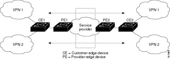
Multi-VRF CE includes these devices:
-
Customer edge (CE) devices provide customers access to the service-provider network over a data link to one or more provider edge routers. The CE device advertises the site’s local routes to the router and learns the remote VPN routes from it. A switch can be a CE.
-
Provider edge (PE) routers exchange routing information with CE devices by using static routing or a routing protocol such as BGP, RIPv2, OSPF, or EIGRP. The PE is only required to maintain VPN routes for those VPNs to which it is directly attached, eliminating the need for the PE to maintain all of the service-provider VPN routes. Each PE router maintains a VRF for each of its directly connected sites. Multiple interfaces on a PE router can be associated with a single VRF if all of these sites participate in the same VPN. Each VPN is mapped to a specified VRF. After learning local VPN routes from CEs, a PE router exchanges VPN routing information with other PE routers by using internal BGP (IBPG).
-
Provider routers or core routers are any routers in the service provider network that do not attach to CE devices.
With multi-VRF CE, multiple customers can share one CE, and only one physical link is used between the CE and the PE. The shared CE maintains separate VRF tables for each customer and switches or routes packets for each customer based on its own routing table. Multi-VRF CE extends limited PE functionality to a CE device, giving it the ability to maintain separate VRF tables to extend the privacy and security of a VPN to the branch office.
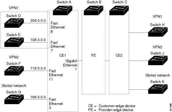
Network Topology
The figure shows a configuration using switches as multiple virtual CEs. This scenario is suited for customers who have low bandwidth requirements for their VPN service, for example, small companies. In this case, multi-VRF CE support is required in the switches. Because multi-VRF CE is a Layer 3 feature, each interface in a VRF must be a Layer 3 interface.
When the CE switch receives a command to add a Layer 3 interface to a VRF, it sets up the appropriate mapping between the VLAN ID and the policy label (PL) in multi-VRF-CE-related data structures and adds the VLAN ID and PL to the VLAN database.
When multi-VRF CE is configured, the Layer 3 forwarding table is conceptually partitioned into two sections:
-
The multi-VRF CE routing section contains the routes from different VPNs.
-
The global routing section contains routes to non-VPN networks, such as the Internet.
VLAN IDs from different VRFs are mapped into different policy labels, which are used to distinguish the VRFs during processing. For each new VPN route learned, the Layer 3 setup function retrieves the policy label by using the VLAN ID of the ingress port and inserts the policy label and new route to the multi-VRF CE routing section. If the packet is received from a routed port, the port internal VLAN ID number is used; if the packet is received from an SVI, the VLAN number is used.
Packet-Forwarding Process
This is the packet-forwarding process in a multi-VRF-CE-enabled network:
-
When the switch receives a packet from a VPN, the switch looks up the routing table based on the input policy label number. When a route is found, the switch forwards the packet to the PE.
-
When the ingress PE receives a packet from the CE, it performs a VRF lookup. When a route is found, the router adds a corresponding MPLS label to the packet and sends it to the MPLS network.
-
When an egress PE receives a packet from the network, it strips the label and uses the label to identify the correct VPN routing table. Then it performs the normal route lookup. When a route is found, it forwards the packet to the correct adjacency.
-
When a CE receives a packet from an egress PE, it uses the input policy label to look up the correct VPN routing table. If a route is found, it forwards the packet within the VPN.
Network Components
To configure VRF, you create a VRF table and specify the Layer 3 interface associated with the VRF. Then configure the routing protocols in the VPN and between the CE and the PE. BGP is the preferred routing protocol used to distribute VPN routing information across the provider’s backbone. The multi-VRF CE network has three major components:
-
VPN route target communities—lists of all other members of a VPN community. You need to configure VPN route targets for each VPN community member.
-
Multiprotocol BGP peering of VPN community PE routers—propagates VRF reachability information to all members of a VPN community. You need to configure BGP peering in all PE routers within a VPN community.
-
VPN forwarding—transports all traffic between all VPN community members across a VPN service-provider network.
VRF-Aware Services
IP services can be configured on global interfaces, and these services run within the global routing instance. IP services are enhanced to run on multiple routing instances; they are VRF-aware. Any configured VRF in the system can be specified for a VRF-aware service.
VRF-Aware services are implemented in platform-independent modules. VRF means multiple routing instances in Cisco IOS. Each platform has its own limit on the number of VRFs it supports.
VRF-aware services have the following characteristics:
-
The user can ping a host in a user-specified VRF.
-
ARP entries are learned in separate VRFs. The user can display Address Resolution Protocol (ARP) entries for specific VRFs.
Multi-VRF CE Configuration Guidelines
Note |
To use multi-VRF CE, you must have the Network Advantage license enabled on your switch. |
-
A switch with multi-VRF CE is shared by multiple customers, and each customer has its own routing table.
-
Because customers use different VRF tables, the same IP addresses can be reused. Overlapped IP addresses are allowed in different VPNs.
-
Multi-VRF CE lets multiple customers share the same physical link between the PE and the CE. Trunk ports with multiple VLANs separate packets among customers. Each customer has its own VLAN.
-
Multi-VRF CE does not support all MPLS-VRF functionality. It does not support label exchange, LDP adjacency, or labeled packets.
-
For the PE router, there is no difference between using multi-VRF CE or using multiple CEs. In Figure 41-6, multiple virtual Layer 3 interfaces are connected to the multi-VRF CE device.
-
The switch supports configuring VRF by using physical ports, VLAN SVIs, or a combination of both. The SVIs can be connected through an access port or a trunk port.
-
A customer can use multiple VLANs as long as they do not overlap with those of other customers. A customer’s VLANs are mapped to a specific routing table ID that is used to identify the appropriate routing tables stored on the switch.
-
The switch supports one global network and up to 256 VRFs.
-
Most routing protocols (BGP, OSPF, RIP, and static routing) can be used between the CE and the PE. However, we recommend using external BGP (EBGP) for these reasons:
-
BGP does not require multiple algorithms to communicate with multiple CEs.
-
BGP is designed for passing routing information between systems run by different administrations.
-
BGP makes it easy to pass attributes of the routes to the CE.
-
-
Multi-VRF CE does not affect the packet switching rate.
-
VPN multicast is not supported.
-
You can enable VRF on a private VLAN, and the reverse.
-
You cannot enable VRF when policy-based routing (PBR) is enabled on an interface, and the reverse.
-
You cannot enable VRF when Web Cache Communication Protocol (WCCP) is enabled on an interface, and the reverse.
 Feedback