Configuring Unicast and Multicast over Point-to-Multipoint GRE

Restrictions for Unicast and Multicast over Point-to-Multipoint GRE

  • This feature is not supported on the C9500-12Q, C9500-16X, C9500-24Q, C9500-40X models of the Cisco Catalyst 9500 Series Switches.

  • IPv6 multicast over mGRE tunnel is not supported.

  • mGRE tunnel maximum transmission unit (MTU) does not get auto updated upon IP MTU change in the underlying network. Tunnel MTU has to be updated manually.

  • mGRE can use only IPv4 as the transport protocol, and can tunnel both IPv4 and IPv6 packets across the underlying network infrastructure.

  • Only IPv4 Next Hop Resolution Protocol (NHRP) is supported, , and as a result, an non-broadcast multiple access network (NBMA) can only be IPv4.

  • Bidirectional Protocol Independent Multicast (PIM) is not supported.

  • Tunnel source can be a Layer 3 etherchannel, loopback, physical, or Switched Virtual Interface (SVI).

  • No feature interactions such as access control list (ACL), Cisco Discovery Protocol, Crypto support, IPSec, or quality of service (QoS) are supported on the mGRE tunnel.

  • All routing protocol that uses mutlicast requires additional configurations.
Prerequisites for Unicast and Multicast over Point-to-Multipoint GRE

  • Before configuring multicast routing over multipoint Generic Routing Encapsulation (mGRE), you should be familiar with the concepts of IP multicast routing technology and mGRE tunneling.

Information About Unicast and Multicast over Point-to-Multipoint GRE

The following sections provide information about unicast and multicast over point-to-multipoint GRE.

Information About NHRP

The Next Hop Resolution Protocol (NHRP) is like the Address Resolution Protocol (ARP) that dynamically maps a non-broadcast multiaccess (NBMA) network instead of manually configuring all the tunnel end points. With NHRP, systems attached to an NBMA network can dynamically learn the NBMA physical address of other systems that are part of that network, allowing these systems to directly communicate.

This protocol provides an ARP-like solution which allow station data-link addresses to dynamically determine NHRP as a client and server protocol, where the hub is the Next Hop Server (NHS) and the spokes are the Next Hop Clients (NHCs). The hub maintains an NHRP database of public interface addresses of each spoke. Each spoke registers its non-NBMA (real) address when it boots up and queries the NHRP database for addresses of the destination spokes to build direct tunnels.

Information About mGRE

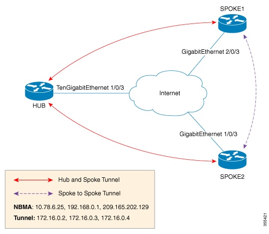
The traditional implementation of a GRE tunnel involves the configuration of a point-to-point tunnel going between two sites. This type of configuration works well when there are limited number of tunnels that need to be configured. However, if there are a large number of spoke sites, the configuration of the hub router and the number of independent IP address ranges (one per tunnel) can quickly get excessive. In such cases, you can use Multipoint GRE (mGRE) at the hub site and normal point-to-point GRE configuration at the spokes. mGRE is configured over an IPv4 core/underlying network and allows multiple destinations to be grouped into a single multipoint interface.

Figure 1. Sample mGRE Configuration at Hub and Spokes

There are two different ways to configure mGRE on the hub and leave a normal GRE configuration on spokes:

  • Static NHRP mapping statements on the hub router

  • Dynamic NHRP mapping on the hub router

In static mappings, the hub router is manually configured with the spoke IP in the NHRP configuration and spokes are configured as point-to-point GRE tunnels. But if there are several branch routers, the configuration on the hub router becomes lengthy, and dynamic NHRP is used on the hub router. When using dynamic NHRP, the hub router requires that each of the spoke routers be configured to register with a Next Hop Server (NHS), which would also typically be the hub router. This NHS keeps track of the NHRP mappings so that the hub device knows where to send traffic (sent to multiple tunnel destinations). For this configuration to work correctly the IP address of the NHS server must also be statically mapped on spoke routers.

With the above hub-spoke topology, the only available way for spokes to send traffic to other spokes is to forward traffic through the hub. This requires an extra hop that may not be required when forwarding traffic. Each of the spokes has the ability to forward traffic directly to each other on the underlying IP network. When this happens, it will be more efficient for the spoke-to-spoke traffic to be routed directly between the spokes without having to jump through the hub router.

If both the hub and spokes are configured to use mGRE then the ability to set up dynamic spoke-to-spoke tunnels is permitted. With this configuration, each spoke still use the hub as an NHS which allows the hub to keep track of each of the spoke sites. It also allows mGRE and NHRP to work together to inform the spokes what the forwarding information is for the other spokes. This information can then be used for each of the spokes to dynamically set up mGRE tunnels between each of the other spokes, as required.

How to Configure Unicast and Multicast over Point-to-Multipoint GRE

The following sections provide configurational information about unicast and multicast over point-to-multipoint GRE

Configuring Unicast mGRE for Hub

Perform this task to configure unicast mGRE for a hub:

SUMMARY STEPS

  1. enable
  2. configure terminal
  3. interface tunnel tunnel-number
  4. tunnel mode gre multipoint
  5. ip ospf network point-to-multipoint
  6. ip address address mask
  7. ipv6 address address prefix
  8. tunnel source address
  9. {ip | ipv6} nhrp network-id id
  10. {ip | ipv6} nhrp registration timeout seconds
  11. {ip | ipv6} nhrp holdtime seconds
  12. {ip | ipv6} nhrp authentication string
  13. ip pim nbma-mode
  14. end

DETAILED STEPS

  Command or Action Purpose

Step 1

enable

Example:


Device>enable

Enables privileged EXEC mode. Enter your password if prompted.

Step 2

configure terminal

Example:


Device#configure terminal

Enters global configuration mode.

Step 3

interface tunnel tunnel-number

Example:


Device(config)#interface tunnel 1

Configures an interface and enters interface configuration mode.

Step 4

tunnel mode gre multipoint

Example:

Device(config-if)#tunnel mode gre multipoint

Configures multipoint GRE as the tunnel mode.

Step 5

ip ospf network point-to-multipoint

Example:

Device(config-if)#ip ospf network point-to-multipoint

If the underlying protocol is OSPF, execute this command to set the network type to point-to-multipoint.

Step 6

ip address address mask

Example:

Device(config-if)#ip address 10.1.1.1 255.255.255.255

Configures the IP address of the tunnel.

Step 7

ipv6 address address prefix

Example:

Device(config-if)#ipv6 address 2001:DB8:1::1

Configures the IPv6 address of the tunnel.

Step 8

tunnel source address

Example:

Device(config-if)#tunnel source TenGigabitEthernet1/0/3

Configures the source IP address of the tunnel.

Step 9

{ip | ipv6} nhrp network-id id

Example:

Device(config-if)#ip nhrp network-id 1

Defines the NHRP domain which differentiates if multiple NHRP domains (GRE tunnel interfaces) are available on the same NHRP router.

Step 10

{ip | ipv6} nhrp registration timeout seconds

Example:

Device(config-if)#ip nhrp registration timeout 30 

Changes the interval that NHRP NHCs take to send NHRP registration requests to configured NHRP NHSs.

Step 11

{ip | ipv6} nhrp holdtime seconds

Example:

Device(config-if)#ip nhrp holdtime 400

Changes the number of seconds that NHRP NBMA addresses are advertised as valid in positive NHRP responses.

Step 12

{ip | ipv6} nhrp authentication string

Example:

Device(config-if)#ip nhrp authentication DMVPN

Specifies an authentication string.

Step 13

ip pim nbma-mode

Example:

Device(config-if)#ip pim nbma-mode

Configures a multiaccess WAN interface to be in non-broadcast multiaccess (NBMA) mode.

Step 14

end

Example:

Device(config-if)#end 

Exits interface configuration mode and returns to priviledged EXEC mode.

Configuring Unicast mGRE at a Spoke

Perform this task to configure unicast mGRE at spokes:

SUMMARY STEPS

  1. enable
  2. configure terminal
  3. interface tunnel tunnel-number
  4. ip nhrp map ip-address nbma-address
  5. {ip | ipv6} nhrp map multicast nbma-address
  6. ip nhrp nhs nhs-address
  7. ipv6 nhrp nhs nhs-address
  8. ipv6 nhrp map address/prefix nbma address
  9. end

DETAILED STEPS

  Command or Action Purpose

Step 1

enable

Example:


Device>enable

Enables privileged EXEC mode. Enter your password if prompted.

Step 2

configure terminal

Example:


Device#configure terminal

Enters global configuration mode.

Step 3

interface tunnel tunnel-number

Example:


Device(config)#interface tunnel 1

Configures an interface and enters interface configuration mode.

Step 4

ip nhrp map ip-address nbma-address

Example:

Device(config-if)#ip nhrp map 10.0.0.1 192.0.0.1

Configures static IP-to-NBMA address mapping of a hub router on the spoke.

Step 5

{ip | ipv6} nhrp map multicast nbma-address

Example:

Device(config-if)#ip nhrp map multicast 10.0.0.2

Enables IP multicast and broadcast packets (example: routing protocol information) to be sent from the spoke to the hub.

Step 6

ip nhrp nhs nhs-address

Example:

Device(config-if)#ip nhrp nhs 192.0.2.1

Enables the spoke to send NHRP registration request to the hub.

  • Here nhs-address is the tunnel address of the hub.

Step 7

ipv6 nhrp nhs nhs-address

Example:

Device(config-if)#ipv6 nhrp nhs 2001:DB8:1::2

Enables the spoke to send an NHRP registration request to the hub. Here nhs-address is the IPv6 address of the hub tunnel.

Step 8

ipv6 nhrp map address/prefix nbma address

Example:

Device(config-if)#ipv6 nhrp map 2001:DB8:1::3 192.0.2.2

Configures static IPv6-to-NBMA address mapping of the hub on the spoke.

Step 9

end

Example:

Device(config-if)#end 

Exits interface configuration mode and returns to privileged EXEC mode.

Configuring Unicast mGRE at the Hub

Perform this task to configure unicast mGRE at the hub:

SUMMARY STEPS

  1. enable
  2. configure terminal
  3. interface tunnel tunnel-number
  4. {ip | ipv6} nhrp map multicast dynamic
  5. {ip | ipv6} next-hop-self eigrp number
  6. {ip | ipv6} split-horizon eigrp number
  7. end

DETAILED STEPS

  Command or Action Purpose

Step 1

enable

Example:


Device>enable

Enables privileged EXEC mode.

  • Enter your password if prompted.

Step 2

configure terminal

Example:


Device#configure terminal

Enters global configuration mode.

Step 3

interface tunnel tunnel-number

Example:


Device(config)#interface tunnel 1

Configures an interface and enters interface configuration mode.

Step 4

{ip | ipv6} nhrp map multicast dynamic

Example:

Device(config-if)#ip nhrp map multicast dynamic

Enables the NHRP server (hub) to create a broadcast/multicast mapping for the spoke when spoke routers register their unicast NHRP mapping with the hub.

Step 5

{ip | ipv6} next-hop-self eigrp number

Example:

Device(config-if)#ip next-hop-self eigrp 10

Enables the hub to use the next received hop while sending routing protocol updates of one spoke to another, so that hosts behind hosts can be reached directly.

Step 6

{ip | ipv6} split-horizon eigrp number

Example:

Device(config-if)#ip split-horizon eigrp 10

Enables routing protocol updates of one spoke to be sent to another spoke.

Step 7

end

Example:

Device(config-if)#end 

Exits interface configuration mode and returns to privileged EXEC mode.

Configuring Multicast mGRE

To configure multicast mGRE, configure unicast mGRE first and then perform this task:

SUMMARY STEPS

  1. enable
  2. configure terminal
  3. interface tunnel tunnel-number
  4. ip pim nbma-mode
  5. ip pim sparse-mode
  6. end

DETAILED STEPS

  Command or Action Purpose

Step 1

enable

Example:


Device>enable

Enables privileged EXEC mode.

  • Enter your password if prompted.

Step 2

configure terminal

Example:


Device#configure terminal

Enters global configuration mode.

Step 3

interface tunnel tunnel-number

Example:


Device(config)#interface tunnel 1

Configures an interface and enters interface configuration mode.

Step 4

ip pim nbma-mode

Example:

Device(config-if)#ip pim nbma-mode

Configures a multiaccess WAN interface to be in NBMA mode.

Step 5

ip pim sparse-mode

Example:

Device(config-if)#ip pim sparse-mode

Enables IPv4 Protocol Independent Multicast (PIM) sparse mode on an interface.

Step 6

end

Example:

Device(config-if)#end 

Exits interface configuration mode and returns to priviledged EXEC mode.

Verifying the mGRE Configuration

Use the following commands to verify the mGRE configuration:

SUMMARY STEPS

  1. enable
  2. show ip nhrp
  3. show ipv6 nhrp
  4. show ip route
  5. show ipv6 route
  6. debug nhrp detail
  7. debug tunnel

DETAILED STEPS


Step 1

enable

Example:


Device>enable

Enables privileged EXEC mode.

  • Enter your password if prompted.

Step 2

show ip nhrp

Displays IPv4 Next Hop Resolution Protocol (NHRP) mapping information.

Example:

Spoke2#show ip nhrp 10.0.0.1

10.0.0.1/32 via 10.0.0.1
   Tunnel0 created 00:03:13, expire 00:06:47
   Type: dynamic, Flags: router used nhop 
   NBMA address: 192.0.0.1 

Spoke2#show ip nhrp 10.0.0.3

10.0.0.3/32 via 10.0.0.3
   Tunnel0 created 22:57:58, never expire 
   Type: static, Flags: used 
   NBMA address: 192.0.0.3

Step 3

show ipv6 nhrp

Displays IPv6 Next Hop Resolution Protocol (NHRP) mapping information.

Example:

HUB#show running-config | interface tunnel6

Building configuration...

Current configuration : 255 bytes
!
interface Tunnel6
 no ip address
 no ip redirects
 ipv6 address 2001:DB8:1::1/64
 ipv6 eigrp 10
 no ipv6 next-hop-self eigrp 10
 no ipv6 split-horizon eigrp 10
 ipv6 nhrp network-id 1
 tunnel source FortyGigabitEthernet1/0/19
 tunnel mode gre multipoint
end 

HUB#show ipv6 nhrp

2001:DB8:1::5/128 via 2001:DB8:1::5
   Tunnel6 created 02:37:30, expire 00:07:29
   Type: dynamic, Flags: registered nhop 
   NBMA address: 192.168.0.2
2001:DB8:1::2A7:42FF:FE83:CEA0/128 via 2001:DB8:1::5
   Tunnel6 created 02:37:30, expire 00:07:29
   Type: dynamic, Flags: registered 
   NBMA address: 192.168.0.2

HUB#

Spoke1#show running-config | interface tunnel6

Building configuration...

Current configuration : 292 bytes
!
interface Tunnel6
 no ip address
 no ip redirects
 ipv6 address 2001::5/64
 ipv6 eigrp 10
 ipv6 nhrp map multicast 192.168.0.3
 ipv6 nhrp map 2001:DB8:1::1/64 192.168.0.3
 ipv6 nhrp network-id 1
 ipv6 nhrp nhs 2001:DB8:1::1
 tunnel source FortyGigabitEthernet1/0/7
 tunnel mode gre multipoint
end

Spoke1#show ipv6 nhrp

2001:DB8:1::/64 via 2001:DB8:1::1
   Tunnel6 created 02:46:17, never expire 
   Type: static, Flags: 
   NBMA address: 192.168.0.3 
2001:DB8:1::2A7:42FF:FE83:CFE0/128 via 2001:DB8:1::2A7:42FF:FE83:CFE0
   Tunnel6 created 02:45:39, never expire 
   Type: static, Flags: nhs-ll 
   NBMA address: 192.168.0.3 
Spoke1#

Step 4

show ip route

Displays IPv4 content of the routing table.

Example:

Spoke2#show ip route 10.0.1.1

Routing entry for 10.0.1.1
  Known via "eigrp 10", distance 90, metric 26880256, type internal
  Redistributing via eigrp 10
  Last update from 10.0.0.3 on Tunnel0, 00:55:34 ago
  Routing Descriptor Blocks:
  * 10.0.0.3, from 10.0.0.3, 00:55:34 ago, via Tunnel0
      Route metric is 26880256, traffic share count is 1
      Total delay is 50010 microseconds, minimum bandwidth is 100 Kbit
      Reliability 255/255, minimum MTU 1472 bytes
      Loading 1/255, Hops 1

HUB#show ip route 10.0.1.2   

Routing entry for 10.0.1.2/24
  Known via "eigrp 10", distance 90, metric 26880256, type internal
  Redistributing via eigrp 10
  Last update from 10.0.0.1 on Tunnel0, 00:56:45 ago
  Routing Descriptor Blocks:
  * 10.0.0.1, from 10.0.0.1, 00:56:45 ago, via Tunnel0
      Route metric is 26880256, traffic share count is 1
      Total delay is 50010 microseconds, minimum bandwidth is 100 Kbit
      Reliability 255/255, minimum MTU 1472 bytes
      Loading 1/255, Hops 1
HUB#

Step 5

show ipv6 route

Displays IPv6 content of the routing table.

Example:

Spoke1#show ipv6 route 2001:DB8:1::/64

Routing entry for 2001:DB8:1::/64
  Known via "eigrp 10", distance 90, metric 27008000, type internal
  Route count is 1/1, share count 0
  Routing paths:
     2001:DB8:1::2A7:42FF:FE83:CFE0, Tunnel6
      From 2001:DB8:1::2A7:42FF:FE83:CFE0
      Last updated 00:03:07 ago
Spoke1#

HUB#show ipv6 route 2001:DB8:1::/64

Routing entry for 2001:DB8:1::/64
  Known via "eigrp 10", distance 90, metric 27008000, type internal
  Route count is 1/1, share count 0
  Routing paths:
    2001:DB8:1::2A7:42FF:FE83:CEA0, Tunnel6
      From 2001:DB8:1::2A7:42FF:FE83:CEA0
      Last updated 00:01:29 ago
HUB#

Step 6

debug nhrp detail

Displays NHRP registration and packet related information.

Step 7

debug tunnel

Displays tunnel state changes and packet related information.


Configuration Examples for Unicast and Multicast over Point-to-Multipoint GRE

The following sections provide configuration examples for unicast and multicast over point-to-multipoint GRE

Example: Configuring Unicast mGRE for Hub

This example shows how to configure unicast mGRE for the hub:

Device>enable
Device#configure terminal
Device(config)#interface tunnel 1
Device(config-if)#tunnel mode gre multipoint
Device(config-if)#ip ospf network point-to-multipoint
Device(config-if)#ip address 10.1.1.1 255.255.255.255
Device(config-if)#ipv6 address 2001:DB8:1::1
Device(config-if)#tunnel source TenGigabitEthernet1/0/3
Device(config-if)#ip nhrp network-id 1
Device(config-if)#ip nhrp registration timeout 30
Device(config-if)#ip nhrp holdtime 400
Device(config-if)#ip nhrp authentication DMVPN
Device(config-if)#ip pim nbma-mode
Device(config-if)#end

Example: Configuring Unicast mGRE at Spoke

This example shows how to configure unicast mGRE at a spoke.

Device>enable
Device#configure terminal
Device(config)#interface tunnel 1
Device(config-if)#ip nhrp map 10.0.0.1 192.0.0.1
Device(config-if)#ip nhrp map multicast 10.0.0.2
Device(config-if)#ip nhrp nhs 192.0.2.1
Device(config-if)#ipv6 nhrp nhs 2001:DB8:1::2
Device(config-if)#ipv6 nhrp map 2001:DB8:1::3 192.0.2.2
Device(config-if)#end

Example: Configuring Unicast mGRE at Hub

This example shows how to configure unicast mGRE at the hub:

Device>enable
Device#configure terminal
Device(config)#interface tunnel 1
Device(config-if)#ip nhrp map multicast dynamic
Device(config-if)#ip next-hop-self eigrp 10
Device(config-if)#ip split-horizon eigrp 10
Device(config-if)#end

Example: Configuring Multicast mGRE

This example shows how to configure multicast mGRE:

Device>enable
Device#configure terminal
Device(config)#interface tunnel 1
Device(config-if)#ip pim nbma-mode
Device(config-if)#ip pim sparse-mode
Device(config-if)#end

Sample mGRE Configuration at Hub and Spokes

Configuration at hub:


Device(config)#interface Tunnel0
Device(config-if)#ip address 172.16.0.2 255.255.255.0
Device(config-if)#no ip redirects
Device(config-if)#ip nhrp authentication DMVPN
Device(config-if)#ip nhrp network-id 1
Device(config-if)#ip nhrp registration timeout 30
Device(config-if)#no ip next-hop-self eigrp 10
Device(config-if)#no ip split-horizon eigrp 10
Device(config-if)#tunnel source TenGigabitEthernet1/0/3
Device(config-if)#tunnel mode gre multipoint
Device(config-if)#tunnel key 4
Device(config-if)#end
Device(config)#interface TenGigabitEthernet1/0/3
Device(config-if)#no switchport
Device(config-if)#ip address 10.78.6.25. 255.255.255.0
Device(config-if)#end

Configuration at spoke1:


Device(config)#interface Tunnel0
Device(config-if)#ip address 172.16.0.4 255.255.255.0
Device(config-if)#no ip redirects
Device(config-if)#ip nhrp authentication DMVPN
Device(config-if)#ip nhrp map 172.16.0.2 10.78.6.25
Device(config-if)#ip nhrp map multicast 10.78.6.25
Device(config-if)#ip nhrp network-id 1
Device(config-if)#ip nhrp nhs 172.16.0.2
Device(config-if)#ip nhrp registration timeout 30
Device(config-if)#tunnel source GigabitEthernet2/0/3
Device(config-if)#tunnel mode gre multipoint
Device(config-if)#tunnel key 4
Device(config-if)#end
Device(config)#interface GigabitEthernet2/0/3
Device(config-if)#no switchport
Device(config-if)#ip address 209.165.202.129 255.255.255.0
Device(config-if)#end

Configuration at spoke2:


Device(config)#interface Tunnel0
Device(config-if)#ip address 172.16.0.3 255.255.255.0
Device(config-if)#no ip redirects
Device(config-if)#ip nhrp authentication DMVPN
Device(config-if)#ip nhrp map 172.16.0.2 10.78.6.25
Device(config-if)#ip nhrp map multicast 10.78.6.25
Device(config-if)#ip nhrp network-id 1
Device(config-if)#ip nhrp nhs 172.16.0.2
Device(config-if)#ip nhrp registration timeout 30
Device(config-if)#tunnel source GigabitEthernet1/0/3
Device(config-if)#tunnel mode gre multipoint
Device(config-if)#tunnel key 4
Device(config-if)#end
Device(config)#interface GigabitEthernet1/0/3
Device(config-if)#no switchport
Device(config-if)#ip address 192.168.0.1 255.255.255.0
Device(config-if)#end

How to Configure Unicast and Multicast over Point-to-Multipoint GRE

Information About Unicast and Multicast over Point-to-Multipoint GRE

Configuration Examples for Unicast and Multicast over Point-to-Multipoint GRE

Feature History and Information for Unicast and Multicast over Point-to-Multipoint GRE

This table provides release and related information for features explained in this module.

These features are available on all releases subsequent to the one they were introduced in, unless noted otherwise.

Release

Feature

Feature Information

Cisco IOS XE Fuji 16.8.1a

Unicast and Multicast over Point-to-Multipoint GRE

The Unicast and Multicast over Point-to-Multipoint GRE feature allows to configure mGRE at the hub site and normal point-to-point GRE configuration at the spokes.

Support for this feature was introduced only on the C9500-32C, C9500-32QC, C9500-48Y4C, and C9500-24Y4C models of the Cisco Catalyst 9500 Series Switches.

Use Cisco Feature Navigator to find information about platform and software image support. To access Cisco Feature Navigator, go to https://cfnng.cisco.com.