Switch Models
|
Switch Model |
Description |
|---|---|
|
Cisco Catalyst 9500 Series Switches |
|
|
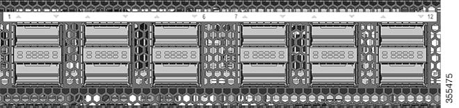
C9500-12Q |
12x40 Gigabit Ethernet QSFP+ ports and 2 power supply slots |
|
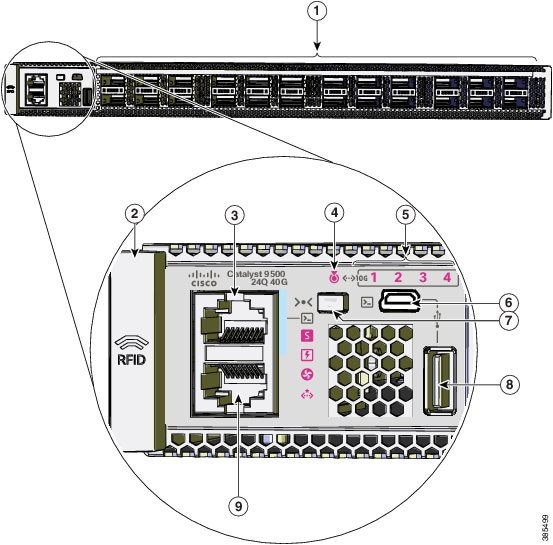
C9500-24Q |
24x40 Gigabit Ethernet QSFP+ ports and 2 power supply slots |
|
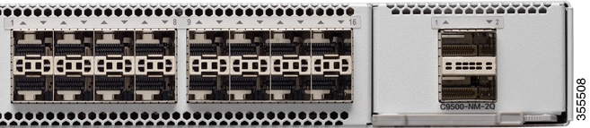
C9500-16X |
16x10 Gigabit Ethernet SFP/SFP+ ports and 2 power supply slots; supports optional network modules on uplinks ports — 8x10 Gigabit Ethernet (SFP/SFP+) and 2x40 Gigabit Ethernet (QSFP+) |
|
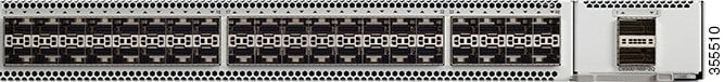
C9500-40X |
40x10 Gigabit Ethernet SFP/SFP+ ports and 2 power supply slots; supports optional network modules on uplink ports — 8x10 Gigabit Ethernet (SFP/SFP+) and 2x40 Gigabit Ethernet (QSFP+) |
|
Cisco Catalyst 9500 Series High Performance Switches |
|
|
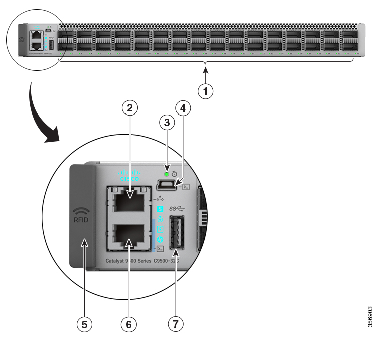
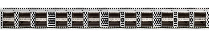
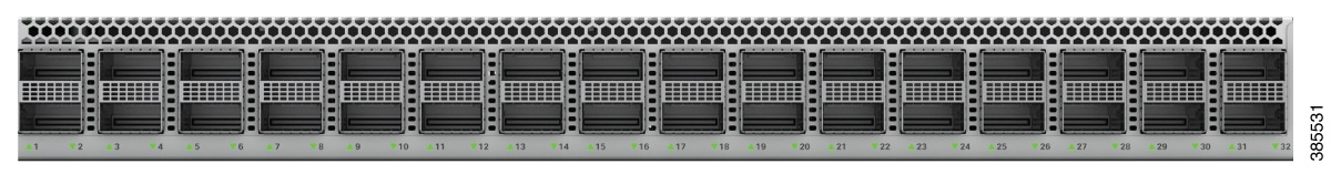
C9500-32C |
32x40G/100G QSFP28 ports and 2 power supply slots |
|
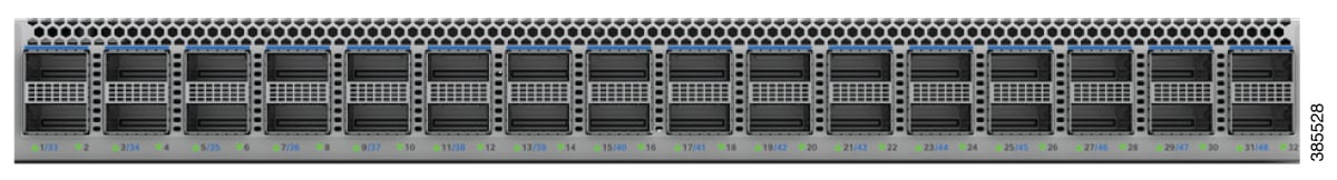
C9500-32QC |
32x40G or 16x100G QSFP28 ports and 2 power supply slots |
|
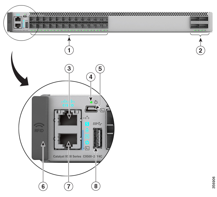
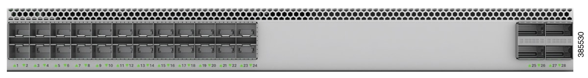
C9500-24Y4C |
24x1G/10G/25G SFP28 ports and 2 power supply slots; 4x40G/100G QSFP28 fixed uplink ports |
|
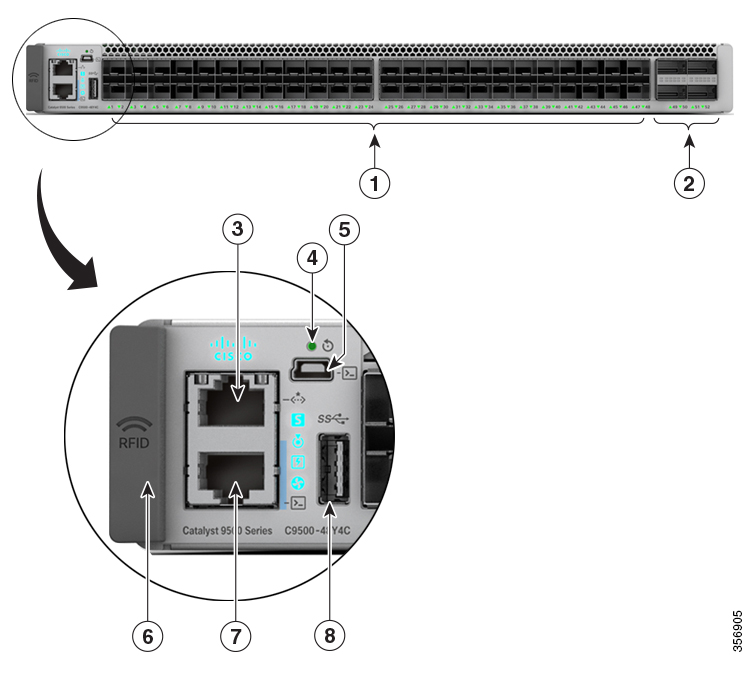
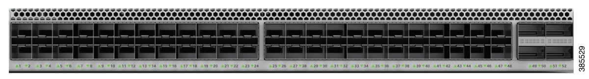
C9500-48Y4C |
48x1G/10G/25G SFP28 ports and 2 power supply slots; 4x40G/100G QSFP28 fixed uplink ports |
|
Switch Model |
Description |
|---|---|
|
C9500-16X-2Q |
16x10 Gigabit Ethernet SFP/SFP+ ports and 2x40 Gigabit Ethernet (QSFP+) network module on uplink ports; and two power supply slots |
|
C9500-40X-2Q |
40 10-Gigabit Ethernet SFP/SFP+ ports and 2x40 Gigabit Ethernet (QSFP+) network module on uplink ports; and two power supply slots |
|
C9500-24X |
16x10 Gigabit Ethernet SFP/SFP+ ports and 8x10 Gigabit Ethernet (SFP/SFP+) network module on uplink ports; and two power supply slots |
|
C9500-48X |
40x10 Gigabit Ethernet SFP/SFP+ ports and 8x10 Gigabit Ethernet (SFP/SFP+) network module on uplink ports; and two power supply slots |


 Feedback