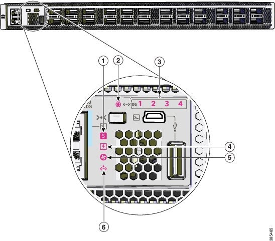
Understanding the LEDs

The switch consists of multiple LEDs to monitor switch activity and performance. You can also monitor the status of the fan tray assembly and the power supplies.

LED Indicators

Figure 1. LEDs on Cisco Catalyst 9500 Series Switches


1

System LED

4

Power Supply Unit(PSU) LED

2

Blue beacon LED

5

Fan LED

3

10G Status LEDs 1

6

Ethernet Management port LED

1 Available only on switches with 10G ports.
Figure 2. LEDs on Cisco Catalyst 9500 Series High Performance Switches


1

Ethernet Management port link activity LED

5

Blue beacon LED

2

Ethernet Management port link status LED

6

Fan LED

3

Reset switch

7

Power Supply Unit (PSU) LED

4

System LED

8

Port LEDs

System LED

The system LED indicates the status of the system.

Table 1. System LED Indicator

Color/State

Description

Off

System is not operational.

Green

System is operating normally without alarms.

Amber

System has triggered a minor environmental alarm.

Red

System has triggered a major environmental alarm.

Power Supply LEDs

Cisco Catalyst 9500 Series Switches

The following table describes the LED indicators when two power supplies modules are installed in the switch.

Table 2. Power Supply LED Indicators for Two PSUs

Color/State

Description

Green

Power supply is operating normally. Both PSUs are in the bay with active power.

Amber

One of the PSU has input loss.

Red

One of the PSU has output failure.

If only one power supply module is installed in the switch and it is operating normally, the power supply LED turns green. If the single power supply unit fails, the switch is powered off.

Cisco Catalyst 9500 Series High Performance Switches

The following table describes the LED indicators when two power supplies modules are installed in the switch.

Table 3. Power Supply LED Indicators for Two PSUs

Color/State

Description

Green

Power supply is operating normally. Both PSUs are in the bay with active power.

Amber

One of the PSU has input loss.

If only one power supply module is installed in the switch and it is operating normally, the power supply LED turns amber. If the single power supply unit fails, the switch is powered off.

Port LEDs and Modes

Cisco Catalyst 9500 Series Switches

Each Ethernet port, 1-Gigabit Ethernet module slot, and 10-Gigabit Ethernet module slot has a port LED. These port LEDs, as a group or individually, display information about the switch and about the individual ports. The port mode determines the type of information shown by the port LEDs.

To select or change a mode, press the Mode button until the desired mode is highlighted. When you change port modes, the meanings of the port LED colors also change.

When you press the Mode button on any switch in the switch stack, all the stack switches change to show the same selected mode. For example, if you press the Mode button on the active switch to show the SPEED LED, all the other switches in the stack also show the SPEED LED.

Table 4. Port Mode LEDs
Mode LED Port Mode Description

STAT

Port status

The port status. This is the default mode.

SPEED

Port speed

The port operating speed: 10, 100, or 1000 Mb/s.

DUPLX

Port duplex mode

The port duplex mode: full duplex or half duplex.

ACTV

Active

The active switch status.

STACK

Stack member status

StackWise port status

Stack member status.

The StackWise port status.

Table 5. Meaning of Switch LED Colors in Different Modes
Port Mode Port LED Color Meaning

STAT (port status)

Off

No link, or port was administratively shut down.

Green

Link present, no activity.

Blinking green

Activity. Port is sending or receiving data.

Alternating green-amber

Link fault. Error frames can affect connectivity, and errors such as excessive collisions, CRC errors, and alignment and jabber errors are monitored for a link-fault indication.

Amber

Port is blocked by Spanning Tree Protocol (STP) and is not forwarding data.

After a port is reconfigured, the port LED can be amber for up to 30 seconds as STP checks the switch for possible loops.

SPEED

10/100/1000/SFP ports

Off

Port is operating at 10 Mb/s.

Green

Port is operating at 100 Mb/s.

Single green flash (on for 100 ms, off for 1900 ms)

Port is operating at 1000 Mb/s.

Blinking twice

Port is operating at 2500, 5000 or 10000 Mb/s

Network module slots

Off

Port is not operating.

Blinking green

Port is operating at up to 10 Gb/s.

DUPLX (duplex)

Off

Port is operating in half duplex.

Green

Port is operating in full duplex.

ACTV (data active switch)

Off

The switch is not the active switch.

Note

 
For a standalone switch, this LED is off.

Green

The switch is the active switch.

Amber

Error during active switch election.

Blinking green

Switch is a standby member of a data stack and assumes active responsibilities if the current active switch fails.

STACK (stack member)

Off

No stack member corresponding to that member number.

Blinking green

Stack member number.

Green

Member numbers of other stack member switches.

Cisco Catalyst 9500 Series High Performance Switches

The port LEDs on the Cisco Catalyst 9500 Series High Performance Switches display only the port status.

Table 6. Meaning of Switch LED Colors for Port Status LED
Port LED Color Meaning

Off

Link is not up.

Green

Link present.

Alternating green-amber

Link fault. Error frames can affect connectivity, and errors such as excessive collisions, CRC errors, and alignment and jabber errors are monitored for a link-fault indication.

Amber

  • Port is blocked by Spanning Tree Protocol (STP) and is not forwarding data. After a port is reconfigured, the port LED can be amber for up to 30 seconds as STP checks the switch for possible loops.

  • Port link is disabled, that is, administratively down.

Beacon LED

The UID and the Beacon LED can be turned on by the administrator to indicate that the switch needs attention. It helps the administrator identify the switch. The beacon can be turned on by either pressing the UID button on the switch front panel, or by using the CLI. There is a blue beacon on the front and rear panel of the switch. The blue beacon on the front panel is a button labeled UID, and on the back panel it is a LED labeled BEACON.

Color/State

Description

Solid blue

The operator has indicated that the system needs attention.

Fan LED

Table 7. Fan LED Indicator

Color/State

Description

Off

The fan is not receiving power; the fans have stopped.

Green

The fan is operating normally.

Amber

The fan has encountered a fault.

Red

One or more fans' tachometer faults have exceeded the maximum limit.

Ethernet Management Port LED

The following table describes the colors and the descriptions of the LEDs for link activity and link status of the Ethernet management port.

Table 8. Ethernet Management Port Link Activity LED
Color Description

Blinking green

Link is up.

Off

Link is down.

Table 9. Ethernet Management Port Link Status LED
Color Description

Solid green

Link is up.

Off

Link is down.