The documentation set for this product strives to use bias-free language. For the purposes of this documentation set, bias-free is defined as language that does not imply discrimination based on age, disability, gender, racial identity, ethnic identity, sexual orientation, socioeconomic status, and intersectionality. Exceptions may be present in the documentation due to language that is hardcoded in the user interfaces of the product software, language used based on RFP documentation, or language that is used by a referenced third-party product. Learn more about how Cisco is using Inclusive Language.
Only Layer 3 Tenant Routed Multicast (TRM) is supported.
Layer 2 TRM is not supported.
TRM works only on the Default Multicast Distribution Tree (MDT).
In the underlay network, TRM is supported only in the PIM-SM mode.
In the underlay network, the spine switch should be configured as the Rendezvous Point (RP).
In the overlay network, TRM is supported in the PIM-SM and PIM-SSM mode.
Only Layer 3 Tenant Routed Multicast (TRM) is supported.
Layer 2 TRM is not supported.
Layer 3 TRM is not supported for IPv6 traffic in the underlay networks.
In the overlay networks, Layer 3 TRM is supported for both IPv4 and IPv6 traffic.
TRM works only on the Default Multicast Distribution Tree (MDT).
In the underlay network, TRM is supported only in the PIM-SM mode. In the overlay network, it is supported in the PIM-SM with
Distributed Anycast-RP mode, PIM-SM with External-RP mode, and PIM-SSM mode.
In the underlay network, the spine switch should be configured as the Rendezvous Point (RP).
In the overlay network, each of the VTEPs must be configured as the RP for TRM in Distributed Anycast-RP mode.
For External RP with EVPN AnycastGW, separate register-source loopback is needed in FHR
E-BGP and I-BGP are supported.
BGP router-reflector is also supported.
Information about Tenant Routed Multicast
TRM enables multicast forwarding in a VXLAN fabric that uses a BGP-based EVPN control plane. TRM provides multi-tenancy aware
multicast forwarding between senders and receivers within the same or different subnets local or across VTEPs.
This feature brings the efficiency of multicast delivery to VXLAN overlay networks. TRM enables the delivery of a customer's
IP multicast traffic in a multi-tenant fabric in an efficient and resilient manner. The delivery of TRM improves Layer-3 overlay
multicast functionality in the networks.
With TRM enabled, multicast forwarding in the underlay is leveraged to replicate VXLAN-encapsulated routed multicast traffic.
A default-MDT is built per-VRF. This is an addition to the existing multicast groups for broadcast and unknown unicast traffic
in a Layer 2 Virtual Network Instance (VNI), and for Layer 2 multicast replication group. The individual multicast group addresses
in the overlay are mapped to the respective underlay multicast address for replication and transport. The advantage of using
a BGP-based approach is that it allows the BGP EVPN VXLAN fabric with TRM to operate as fully distributed Overlay Rendezvous-Point
(RP), with the RP presence on every edge-device or VTEP.
A multicast-enabled data center fabric is typically part of an overall multicast network. Multicast sources, receivers, and
multicast rendezvous points, might reside inside the data center but might also be inside the campus or externally reachable
via the WAN. TRM allows a seamless integration with existing multicast networks.
For IPv4 and IPv6 multicast traffic, TRM uses BGP EVPN and MVPN routes to perform multicast routing.
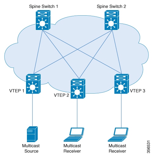
Figure 1. Tenant Routed Multicast Topology
Source detection triggers advertising of EVPN route type 2 in the EVPN fabric. This EVPN route installed in Layer 3 RIB at
a receiver VTEP is used as the RPF route towards the source. Thus, if the source is undetected, the RPF for the (S,G) entry
is not found. In this case, either RPF remains NULL or a less specific route is installed if present in the RIB.
In EVPN-VXLAN network, TRM is supported in the overlay network in PIM-SM and PIM-SSM modes.
PIM-SM with Distributed Anycast-RP Mode
In PIM-SM with Distributed Anycast-RP Mode, each of the VTEPs must be the RP in the overlay network for their respective groups.
The rendezvous points in the underlay network must be configured on the spine switches. All the VTEPs do not need to be BGP
peers. There can be BGP peering between the VTEPs and the spine switches with the spine switches acting as route reflectors.
When a VTEP discovers a source device, it sends Source A-D Routes (MVPN Route Type 5) to all the other VTEPs. Based on these
Source A-D routes, the other VTEPs send (S,G) join requests as MVPN route type 7 to the source VTEP.
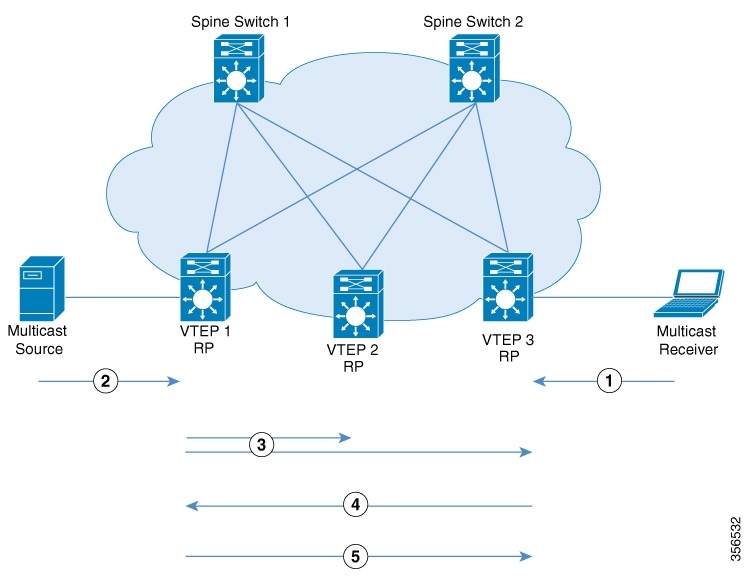
Figure 2. PIM-SM with Distributed Anycast-RP Mode
IGMP Join for (*,G) from Receiver Device to VTEP 3.
Data Traffic from Source Device to VTEP 1.
Source A-D Route for (S,G) from VTEP 1 to VTEP 2 and VTEP 3.
MVPN route type 7 from VTEP 3 to VTEP 1.
Data Traffic from VTEP 1 to VTEP 3.
In PIM-SM with Distributed Anycast-RP Mode, the following sequence of events occurs:
Receiver sends (*,G) IGMP Join to VTEP 3. Since VTEP 3 is an RP, (*,G) is created at VTEP 3.
The source device starts streaming data and (S,G) is created on VTEP 1.
Note
When PIM-SM with Distributed Anycast-RP Mode is enabled, the first packet is dropped.
VTEP 1 performs self-source-registration since it is also an RP.
The source VTEP (VTEP 1) advertises Source A-D Routes (also called MVPN route type 5) for (S,G) to all the other VTEPs which
are BGP peers in the MVPN address family.
VTEP 2 and VTEP 3 receive and install the Source A-D Routes for (S,G).
(S,G) is created at VTEP 3. VTEP 3 now has an overlay route for (S,G) and also has a unicast route to the source device from
the EVPN Control plane. It then sends an MVPN route type 7 (S,G) BGP join to VTEP 1 and starts accepting traffic.
VTEP 1 receives and installs MVPN route type 7 from VTEP 3. It uses the Layer 3 VNI’s SVI as the forwarding interface for
(S,G) and starts forwarding traffic.
PIM-SSM Mode
In PIM-SSM Mode, the Source A-D route (MVPN route type 5) is not needed for the multicast convergence to happen. The receiver
VTEP does not wait to receive the Source A-D route to send the MVPN route type 7.
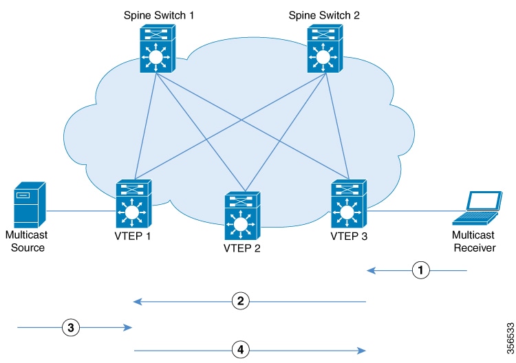
Figure 3. PIM-SSM Mode
IGMP Join for (S,G) from Receiver Device to VTEP 3.
MVPN route type 7.
Data Traffic for (S,G) from Source Device to VTEP 1.
Data Traffic from VTEP 1 to VTEP 3.
In PIM-SSM Mode, the following sequence of events occurs:
When the source device sends a unicast packet, VTEP 1 sends out EVPN routes to all the other VTEPs, letting them know that
the packet is from the source device.
The receiver sends an (S,G) IGMP join towards VTEP 3 and an (S,G) entry is created.
VTEP 3 performs an RPF lookup for the source device. If the SVI of the Layer 3 VNI is found to be the RPF interface, VTEP
3 sends MVPN route type 7 towards VTEP 1.
VTEP 1 receives and installs the MVPN route type 7. VTEP 1 creates an (S,G) entry, using the Layer 3 VNI’s SVI as the forwarding
interface for (S,G).
The source device sends (S,G) data to VTEP 1 which starts forwarding the traffic to VTEP 3.
How to Configure Tenant Routed Multicast
Prerequisites to Configuring TRM
Before configuring TRM, ensure that EVPN VXLAN Layer 2 and Layer 3 Overlay networks have been configured. See How to Configure EVPN VXLAN Integrated Routing and Bridging for detailed steps to configure Layer 2 and Layer 3 overlay networks.
Perform the following set of procedures to configure TRM in an EVPN VXLAN network:
Configuring the Default Multicast Distribution Tree in the VRF
To configure the default MDT for TRM, perform the following steps:
Procedure
Command or Action
Purpose
Step 1
enable
Example:
Device> enable
Enables privileged EXEC mode.
Enter your password, if prompted.
Step 2
configure terminal
Example:
Device# configure terminal
Enters global configuration mode.
Step 3
vrf definition vrf-name
Example:
Device(config)# vrf definition green
Names the VRF and enters VRF configuration mode.
Step 4
mdt default vxlan group-address
Example:
Device(config-vrf)# mdt default vxlan 225.2.2.2
Configures the multicast group address range for data MDT groups for a VRF in a VXLAN.
This command creates a tunnel interface.
By default, the destination address of the tunnel header is the group-address argument.
Step 5
mdt auto-discovery vxlan
Example:
Device(config-vrf)# mdt auto-discovery vxlan
Enables VXLAN with BGP auto-discovery.
Step 6
mdt overlay use-bgp spt-only
Example:
Device(config-vrf)# mdt overlay use-bgp spt-only
Specifies BGP as the overlay protocol.
Step 7
end
Example:
Device(config-vrf)# end
Returns to privileged EXEC mode.
Configuring Multicast Routing on the Overlay VRF
To enable multicast routing on the overlay VRF, perform the following steps:
Procedure
Command or Action
Purpose
Step 1
enable
Example:
Device> enable
Enables privileged EXEC mode.
Enter your password, if prompted.
Step 2
configure terminal
Example:
Device# configure terminal
Enters global configuration mode.
Step 3
ip multicast-routing vrf vrf-name
Example:
Device(config)# ip multicast-routing vrf green
Enables IP multicast forwarding on the overlay VRF.
Step 4
end
Example:
Device(config)# end
Returns to privileged EXEC mode.
Configuring Multicast on Switch Virtual Interfaces for the Core-facing and Access-facing VLANs
To configure multicast on SVIs for the core-facing and access-facing VLANs on the VTEP, perform the following steps:
Procedure
Command or Action
Purpose
Step 1
enable
Example:
Device> enable
Enables privileged EXEC mode.
Enter your password, if prompted.
Step 2
configure terminal
Example:
Device# configure terminal
Enters global configuration mode.
Step 3
interface vlan core-facing-vlan-id
Example:
Device(config)# interface vlan 200
Enters interface configuration mode for the specified VLAN.
Step 4
ip pim sparse-mode
Example:
Device(config-if) # ip pim sparse-mode
Enables multicast on the core-facing SVI.
Step 5
exit
Example:
Device(config-if)# end
Returns to privileged EXEC mode.
Step 6
interface vlan access-facing-vlan-id
Example:
Device(config)# interface vlan 202
Enters interface configuration mode for the specified VLAN.
Step 7
ip pim sparse-mode
Example:
Device(config-if) # ip pim sparse-mode
Enables multicast on the access-facing SVI where sources or receivers are connected.
Repeat this step for all the access-facing SVIs that are part of the Layer 2 VNI where sources and receivers are connected.
Step 8
end
Example:
Device(config-if)# end
Returns to privileged EXEC mode.
Configuring BGP with MVPN Address Family on VTEP
To configure BGP on a VTEP with MVPN address family, perform the following steps:
Procedure
Command or Action
Purpose
Step 1
enable
Example:
Device> enable
Enables privileged EXEC mode.
Enter your password, if prompted.
Step 2
configure terminal
Example:
Device# configure terminal
Enters global configuration mode.
Step 3
router bgp autonomous-system-number
Example:
Device(config)# router bgp 1
Enables a BGP routing process, assigns it an autonomous system number, and enters router configuration mode.
Step 4
address-family ipv4 mvpn
Example:
Device(config-router)# address-family ipv4 mvpn
Specifies the MVPN address family and enters address family configuration mode.
(Optional) Sets the minimum route advertisement interval (MRAI) between the sending of BGP routing updates.
Step 8
exit-address-family
Example:
Device(config-router-af)# exit-address-family
Exits address family configuration mode and returns to router configuration mode.
Step 9
end
Example:
Device(config-router)# end
Returns to privileged EXEC mode.
Configuring RP for Underlay Network
To configure RP for the underlay network, perform the following steps:
Procedure
Command or Action
Purpose
Step 1
enable
Example:
Device> enable
Enables privileged EXEC mode.
Enter your password, if prompted.
Step 2
configure terminal
Example:
Device# configure terminal
Enters global configuration mode.
Step 3
ip pim rp-address ip-address-of-rp
Example:
Device(config)# ip pim rp-address <rp-ip-address>
Configures the RP in the underlay network.
For information about RP redundancy, see to IP Multicast Routing Configuration Guide.
Step 4
end
Example:
Device(config)# end
Returns to privileged EXEC mode.
Configuring RP and SSM for Overlay Network
To configure RP and SSM for the overlay network, perform the following steps:
Procedure
Command or Action
Purpose
Step 1
enable
Example:
Device> enable
Enables privileged EXEC mode.
Enter your password, if prompted.
Step 2
configure terminal
Example:
Device# configure terminal
Enters global configuration mode.
Step 3
interface loopback-interface
Example:
Device(config)# interface Loopback 13
Enters interface configuration mode for the specified Loopback interface.
Step 4
vrf forwarding vrf-name
Example:
Device(config-if)# vrf forwarding green
Configures forwarding table for the Loopback interface.
Step 5
ip-address ip-address subnet-mask
Example:
Device(config-if)# ip address 10.1.13.13 255.255.255.255
Configures the IP address for the Loopback interface.
Step 6
ip pim sparse-mode
Example:
Device(config-if)# ip pim sparse-mode
Enables PIM sparse mode on the Loopback interface.
Note
Enable PIM sparse mode only if EVPN VXLAN Layer 2 overlay network is also configured on the VTEP with underlay multicast as
the mechanism for forwarding BUM traffic.
Step 7
exit
Example:
Device(config-if)# exit
Returns to global configuration mode.
Step 8
ip pim [ vrf vrf-name ] ssm { default | range access-list }
Example:
Device(config)# ip pim vrf green ssm default
Configures an SSM range for TRM.
The default keyword defines the SSM range access list as 232/8.
The range keyword specifies the standard IP access list number or name that defines the SSM range.
Step 9
ip pim vrf vrf-name rp-address loopback-address-of-vtep
Example:
Device(config)# ip pim vrf green rp-address 10.1.13.13
Configures the address of the loopback interface of the local VTEP as the PIM RP for the multicast group in PIM-SM with Distributed
Anycast RP mode.
Note
The loopback interface specified must be part of the same VRF.
Step 10
end
Example:
Device(config)# end
Returns to privileged EXEC mode.
Configuration Examples for Tenant Routed Multicast
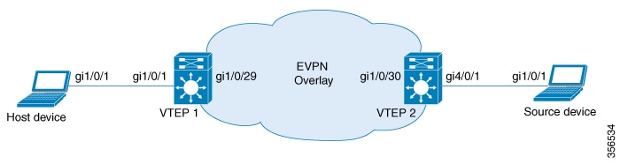
This section provides an example for TRM configuration. The following example shows a sample configuration for a VXLAN network
with a receiver device and a source device connected to VTEP 1 and VTEP 2 respectively, with TRM enabled.
Table 1. Configuration Example for a VXLAN Network with the Source Device and Host Device connected to two VTEPs with TRM Enabled
VTEP 1
VTEP 2
VTEP1# show running-config
!
hostname VTEP1
!
vrf definition green
 rd 103:2
 !
 address-family ipv4
  mdt auto-discovery vxlan
  mdt default vxlan 239.1.1.1
  mdt overlay use-bgp spt-only
  route-target export 103:2
  route-target import 104:2
  route-target export 103:2 stitching
  route-target import 104:2 stitching
 exit-address-family
 !
!
ip routing
ip multicast-routing
ip multicast-routing vrf green
!
!
l2vpn evpn
 replication-type static
 router-id Loopback0
 default-gateway advertise
!
l2vpn evpn instance 1 vlan-based
 encapsulation vxlan
 route-target export 103:1
 route-target import 104:1
!
l2vpn evpn instance 2 vlan-based
 encapsulation vxlan
!
!
system mtu 9150
!
vlan configuration 200
 member vni 5000
vlan configuration 201
 member evpn-instance 1 vni 6000
vlan configuration 202
 member evpn-instance 2 vni 7000
!
!
interface Loopback0
 ip address 10.1.1.10 255.255.255.255
 ip pim sparse-mode
!
interface Loopback13
 vrf forwarding green
 ip address 10.1.13.13 255.255.255.0
 ip pim sparse-mode
 ipv6 enable
!
!
interface GigabitEthernet1/0/1
 description access interface
 switchport mode trunk
!
interface GigabitEthernet1/0/29
 description core-underlay-interface
 no switchport
 ip address 172.16.1.29 255.255.255.0
 ip pim sparse-mode
!
interface Vlan200
 description core svi for l3vni
 vrf forwarding green
 ip unnumbered Loopback0
 ip pim sparse-mode
 ipv6 enable
 no autostate
!
interface Vlan201
 description vni 6000 default-gateway
 vrf forwarding green
 ip address 192.168.1.201 255.255.255.0
 ip pim sparse-mode
 ipv6 enable
!
interface Vlan202
 description vni 7000 default-gateway
 vrf forwarding green
 ip address 192.168.2.202 255.255.255.0
 ip pim sparse-mode
!
!
interface nve10
 no ip address
 source-interface Loopback0
 host-reachability protocol bgp
 member vni 6000 mcast-group 231.1.1.1
 member vni 7000 mcast-group 231.1.1.1
 member vni 5000 vrf green
!
router ospf 1
 router-id 10.1.1.10
 network 10.1.1.0 0.0.0.255 area 0
 network 172.16.1.0 0.0.0.255 area 0
!
router bgp 10
 bgp router-id interface Loopback0
 bgp log-neighbor-changes
 bgp update-delay 1
 no bgp default ipv4-unicast
 neighbor 10.2.2.20 remote-as 10
 neighbor 10.2.2.20 update-source Loopback0
 !
 address-family ipv4
 exit-address-family
 !
 address-family ipv4 mvpn
  neighbor 10.2.2.20 activate
  neighbor 10.2.2.20 send-community both
 exit-address-family
 !
 address-family l2vpn evpn
  neighbor 10.2.2.20 activate
  neighbor 10.2.2.20 send-community both
 exit-address-family
 !
 address-family ipv4 vrf green
  advertise l2vpn evpn
  redistribute connected
  redistribute static
 exit-address-family
 !
!
ip pim rp-address 10.1.1.10
ip pim vrf green rp-address 10.1.13.13
!
!
end
VTEP2# show running-config
!
hostname VTEP2
!
vrf definition green
 rd 104:2
 !
 address-family ipv4
  mdt auto-discovery vxlan
  mdt default vxlan 239.1.1.1
  mdt overlay use-bgp spt-only
  route-target export 104:2
  route-target import 103:2
  route-target export 104:2 stitching
  route-target import 103:2 stitching
 exit-address-family
 !
!
ip routing
ip multicast-routing
ip multicast-routing vrf green
!
!
l2vpn evpn
 replication-type static
 router-id Loopback0
 default-gateway advertise
!
l2vpn evpn instance 1 vlan-based
 encapsulation vxlan
 route-target export 104:1
 route-target import 103:1
!
l2vpn evpn instance 2 vlan-based
 encapsulation vxlan
!
!
system mtu 9150
!
vlan configuration 200
 member vni 5000
vlan configuration 201
 member evpn-instance 1 vni 6000
vlan configuration 202
 member evpn-instance 2 vni 7000
!
!
interface Loopback0
 ip address 10.2.2.20 255.255.255.255
 ip pim sparse-mode
!
interface Loopback14
 vrf forwarding green
 ip address 10.1.14.14 255.255.255.0
 ip pim sparse-mode
 ipv6 address 2001:200::14:14/128
 ipv6 enable
!
interface GigabitEthernet4/0/1
description access interface
 switchport mode trunk
!
interface GigabitEthernet1/0/30
 description core-underlay-interface
 no switchport
 ip address 172.16.1.30 255.255.255.0
 ip pim sparse-mode
!
interface Vlan200
 description core svi for l3vni
 vrf forwarding green
 ip unnumbered Loopback0
 ip pim sparse-mode
 ipv6 enable
 no autostate
!
interface Vlan201
 vrf forwarding green
 ip address 192.168.1.201 255.255.255.0
 ip pim sparse-mode
 ipv6 address 2001:DB8:201::201/64
 ipv6 enable
!
interface Vlan202
 description vni 7000 default-gateway
 vrf forwarding green
 ip address 192.168.2.202 255.255.255.0
 ip pim sparse-mode
!
!
interface nve10
 no ip address
 source-interface Loopback0
 host-reachability protocol bgp
 member vni 6000 mcast-group 231.1.1.1
 member vni 7000 mcast-group 231.1.1.1
 member vni 5000 vrf green
!
router ospf 1
 router-id 10.2.2.20
 network 10.2.2.0 0.0.0.255 area 0
 network 172.16.1.0 0.0.0.255 area 0
!
router bgp 10
 bgp router-id interface Loopback0
 bgp log-neighbor-changes
 bgp update-delay 1
 no bgp default ipv4-unicast
 neighbor 10.1.1.10 remote-as 10
 neighbor 10.1.1.10 update-source Loopback0
 !
 address-family ipv4
 exit-address-family
 !
 address-family ipv4 mvpn
  neighbor 10.1.1.10 activate
  neighbor 10.1.1.10 send-community both
 exit-address-family
 !
 address-family l2vpn evpn
  neighbor 10.1.1.10 activate
  neighbor 10.1.1.10 send-community both
 exit-address-family
 !
 address-family ipv4 vrf green
  advertise l2vpn evpn
  redistribute connected
  redistribute static
 exit-address-family
 !
!
ip pim rp-address 10.1.1.10
ip pim vrf green rp-address 10.1.14.14
!
!
end
The following examples provide outputs for show commands on VTEP 1 and VTEP 2 in the topology configured above.
The following example shows the output for the show nve peers command on VTEP 1:
VTEP1# show nve peers
Interface  VNI      Type Peer-IP          RMAC/Num_RTs   eVNI     state flags UP time
nve10      5000     L3CP 10.2.2.20        380e.4d9b.6a4a 5000       UP  A/-/4 03:22:40
nve10      6000     L2CP 10.2.2.20        14             6000       UP   N/A  03:22:19
nve10      7000     L2CP 10.2.2.20        6              7000       UP   N/A  03:22:19
VTEP 2
The following example shows the output for the show nve peers command on VTEP 2:
VTEP2# show nve peers
Interface  VNI      Type Peer-IP          RMAC/Num_RTs   eVNI     state flags UP time
nve10      5000     L3CP 10.1.1.10        a0f8.4910.bce2 5000       UP  A/M/4 03:22:27
nve10      6000     L2CP 10.1.1.10        6              6000       UP   N/A  03:22:27
nve10      7000     L2CP 10.1.1.10        4              7000       UP   N/A  03:22:27
show l2vpn evpn peers vxlan
VTEP 1
The following example shows the output for the show l2vpn evpn peers vxlan command on VTEP 1:
VTEP1# show l2vpn evpn peers vxlan
Interface VNI      Peer-IP                   Num routes eVNI     UP time
--------- -------- ------------------------  ---------- -------- --------
nve10     6000     10.2.2.20                 5          6000     01:34:50
nve10     7000     10.2.2.20                 6          7000     01:34:50
VTEP 2
The following example shows the output for the show l2vpn evpn peers vxlan command on VTEP 2:
VTEP2# show l2vpn evpn peers vxlanInterface VNI      Peer-IP                   Num routes eVNI     UP time
--------- -------- ------------------------  ---------- -------- --------
nve10     6000     10.1.1.10                 7          6000     01:35:23
nve10     7000     10.1.1.10                 6          7000     01:35:23
show ip igmp vrf green groups
VTEP 1
The following example shows the output for the show ip igmp vrf green groups command on VTEP 1:
VTEP1# show ip igmp vrf green groups
IGMP Connected Group Membership
Group Address    Interface                Uptime    Expires   Last Reporter   Group Accounted
229.1.1.1        Vlan201                  04:08:35  00:02:16  192.168.1.81
224.0.1.40       Loopback13               06:35:55  00:02:05  10.1.13.13
VTEP 2
The following example shows the output for the show ip igmp vrf green groups command on VTEP 2:
VTEP2# show ip igmp vrf green groups
IGMP Connected Group Membership
Group Address    Interface                Uptime    Expires   Last Reporter   Group Accounted
224.0.1.40       Loopback14               05:11:42  00:02:18  10.1.14.14
show bgp ipv4 mvpn all
VTEP 1
The following example shows the output for the show bgp ipv4 mvpn all command on VTEP 1:
VTEP1# show bgp ipv4 mvpn all
BGP table version is 22, local router ID is 10.1.1.10
Status codes: s suppressed, d damped, h history, * valid, > best, i - internal,
              r RIB-failure, S Stale, m multipath, b backup-path, f RT-Filter,
              x best-external, a additional-path, c RIB-compressed,
              t secondary path, L long-lived-stale,
Origin codes: i - IGP, e - EGP, ? - incomplete
RPKI validation codes: V valid, I invalid, N Not found
     Network          Next Hop            Metric LocPrf Weight Path
Route Distinguisher: 103:2 (default for vrf green)
 *>i  [5][103:2][192.168.2.88][229.1.1.1]/18
                      10.2.2.20                0    100      0 ?
Route Distinguisher: 104:2
 *>i  [5][104:2][192.168.2.88][229.1.1.1]/18
                      10.2.2.20                0    100      0 ?
Route Distinguisher: 10.2.2.20:2
 *>   [7][10.2.2.20:2][10][192.168.2.88/32][229.1.1.1/32]/22
                      0.0.0.0                            32768 ?
VTEP 2
The following example shows the output for the show bgp ipv4 mvpn all command on VTEP 2:
VTEP2# show bgp ipv4 mvpn all
BGP table version is 24, local router ID is 10.2.2.20
Status codes: s suppressed, d damped, h history, * valid, > best, i - internal,
              r RIB-failure, S Stale, m multipath, b backup-path, f RT-Filter,
              x best-external, a additional-path, c RIB-compressed,
              t secondary path, L long-lived-stale,
Origin codes: i - IGP, e - EGP, ? - incomplete
RPKI validation codes: V valid, I invalid, N Not found
     Network          Next Hop            Metric LocPrf Weight Path
Route Distinguisher: 104:2 (default for vrf green)
 *>   [5][104:2][192.168.2.88][229.1.1.1]/18
                      0.0.0.0                            32768 ?
 *>i  [7][104:2][10][192.168.2.88/32][229.1.1.1/32]/22
                      10.1.1.10                0    100      0 ?
Route Distinguisher: 10.2.2.20:2
 *>i  [7][10.2.2.20:2][10][192.168.2.88/32][229.1.1.1/32]/22
                      10.1.1.10                0    100      0 ?
show ip mroute vrf green
VTEP 1
The following example shows the output for the show ip mroute vrf green command on VTEP 1:
VTEP1# show ip mroute vrf greenIP Multicast Routing Table
Flags: D - Dense, S - Sparse, B - Bidir Group, s - SSM Group, C - Connected,
       L - Local, P - Pruned, R - RP-bit set, F - Register flag,
       T - SPT-bit set, J - Join SPT, M - MSDP created entry, E - Extranet,
       X - Proxy Join Timer Running, A - Candidate for MSDP Advertisement,
       U - URD, I - Received Source Specific Host Report,
       Z - Multicast Tunnel, z - MDT-data group sender,
       Y - Joined MDT-data group, y - Sending to MDT-data group,
       G - Received BGP C-Mroute, g - Sent BGP C-Mroute,
       N - Received BGP Shared-Tree Prune, n - BGP C-Mroute suppressed,
       Q - Received BGP S-A Route, q - Sent BGP S-A Route,
       V - RD & Vector, v - Vector, p - PIM Joins on route,
       x - VxLAN group, c - PFP-SA cache created entry,
       * - determined by Assert, # - iif-starg configured on rpf intf
Outgoing interface flags: H - Hardware switched, A - Assert winner, p - PIM Join
 Timers: Uptime/Expires
 Interface state: Interface, Next-Hop or VCD, State/Mode
(*, 229.1.1.1), 04:11:11/stopped, RP 10.1.13.13, flags: SJC
  Incoming interface: Null, RPF nbr 0.0.0.0
  Outgoing interface list:
    Vlan201, Forward/Sparse, 04:11:11/00:02:40
(192.168.2.88, 229.1.1.1), 00:02:42/00:00:17, flags: gQ
  Incoming interface: Vlan200, RPF nbr 10.2.2.20
  Outgoing interface list:
    Vlan201, Forward/Sparse, 00:02:42/00:02:40
(*, 224.0.1.40), 04:44:21/00:02:34, RP 10.1.13.13, flags: SJCL
  Incoming interface: Null, RPF nbr 0.0.0.0
  Outgoing interface list:
    Loopback13, Forward/Sparse, 04:44:21/00:02:34
VTEP 2
The following example shows the output for the show ip mroute vrf green command on VTEP 2:
VTEP2# show ip mroute vrf green
IP Multicast Routing Table
Flags: D - Dense, S - Sparse, B - Bidir Group, s - SSM Group, C - Connected,
       L - Local, P - Pruned, R - RP-bit set, F - Register flag,
       T - SPT-bit set, J - Join SPT, M - MSDP created entry, E - Extranet,
       X - Proxy Join Timer Running, A - Candidate for MSDP Advertisement,
       U - URD, I - Received Source Specific Host Report,
       Z - Multicast Tunnel, z - MDT-data group sender,
       Y - Joined MDT-data group, y - Sending to MDT-data group,
       G - Received BGP C-Mroute, g - Sent BGP C-Mroute,
       N - Received BGP Shared-Tree Prune, n - BGP C-Mroute suppressed,
       Q - Received BGP S-A Route, q - Sent BGP S-A Route,
       V - RD & Vector, v - Vector, p - PIM Joins on route,
       x - VxLAN group, c - PFP-SA cache created entry,
       * - determined by Assert, # - iif-starg configured on rpf intf
Outgoing interface flags: H - Hardware switched, A - Assert winner, p - PIM Join
 Timers: Uptime/Expires
 Interface state: Interface, Next-Hop or VCD, State/Mode
(*, 229.1.1.1), 00:53:58/stopped, RP 10.1.14.14, flags: SPF
  Incoming interface: Null, RPF nbr 0.0.0.0
  Outgoing interface list: Null
(192.168.2.88, 229.1.1.1), 00:53:58/00:01:56, flags: FTGqx
  Incoming interface: Vlan202, RPF nbr 0.0.0.0
  Outgoing interface list:
    Vlan200, Forward/Sparse, 00:03:06/stopped
(*, 224.0.1.40), 04:46:21/00:02:48, RP 10.1.14.14, flags: SJCL
  Incoming interface: Null, RPF nbr 0.0.0.0
  Outgoing interface list:
    Loopback14, Forward/Sparse, 04:46:21/00:02:48
show ip mfib vrf green
VTEP 1
The following example shows the output for the show ip mfib vrf green command on VTEP 1:
VTEP1# show ip mfib vrf green
Entry Flags:    C - Directly Connected, S - Signal, IA - Inherit A flag,
                ET - Data Rate Exceeds Threshold, K - Keepalive
                DDE - Data Driven Event, HW - Hardware Installed
                ME - MoFRR ECMP entry, MNE - MoFRR Non-ECMP entry, MP - MFIB
                MoFRR Primary, RP - MRIB MoFRR Primary, P - MoFRR Primary
                MS  - MoFRR  Entry in Sync, MC - MoFRR entry in MoFRR Client.
I/O Item Flags: IC - Internal Copy, NP - Not platform switched,
                NS - Negate Signalling, SP - Signal Present,
                A - Accept, F - Forward, RA - MRIB Accept, RF - MRIB Forward,
                MA - MFIB Accept, A2 - Accept backup,
                RA2 - MRIB Accept backup, MA2 - MFIB Accept backup
Forwarding Counts: Pkt Count/Pkts per second/Avg Pkt Size/Kbits per second
Other counts:      Total/RPF failed/Other drops
I/O Item Counts:   HW Pkt Count/FS Pkt Count/PS Pkt Count   Egress Rate in pps
VRF green
 (*,224.0.0.0/4) Flags: C HW
   SW Forwarding: 0/0/0/0, Other: 0/0/0
   HW Forwarding:   0/0/0/0, Other: 0/0/0
 (*,224.0.1.40) Flags: C HW
   SW Forwarding: 0/0/0/0, Other: 0/0/0
   HW Forwarding:   0/0/0/0, Other: 0/0/0
   Tunnel9 Flags: A
   Loopback13 Flags: F IC NS
     Pkts: 0/0/0 Rate: 0 pps
 (*,229.1.1.1) Flags: C HW
   SW Forwarding: 0/0/0/0, Other: 0/0/0
   HW Forwarding:   0/0/0/0, Other: 0/0/0
   Tunnel9 Flags: A
   Vlan201 Flags: F NS
     Pkts: 0/0/0 Rate: 0 pps
 (192.168.2.88,229.1.1.1) Flags: HW
   SW Forwarding: 0/0/0/0, Other: 0/0/0
   HW Forwarding:   117/0/126/0, Other: 0/0/0
   Tunnel9 Flags: A
   Vlan200, VXLAN Decap Flags: NS
   Vlan201 Flags: F NS
     Pkts: 0/0/0 Rate: 0 pps
VTEP 2
The following example shows the output for the show ip mfib vrf green command on VTEP 2:
VTEP2# show ip mfib vrf green
Entry Flags:    C - Directly Connected, S - Signal, IA - Inherit A flag,
                ET - Data Rate Exceeds Threshold, K - Keepalive
                DDE - Data Driven Event, HW - Hardware Installed
                ME - MoFRR ECMP entry, MNE - MoFRR Non-ECMP entry, MP - MFIB
                MoFRR Primary, RP - MRIB MoFRR Primary, P - MoFRR Primary
                MS  - MoFRR  Entry in Sync, MC - MoFRR entry in MoFRR Client.
I/O Item Flags: IC - Internal Copy, NP - Not platform switched,
                NS - Negate Signalling, SP - Signal Present,
                A - Accept, F - Forward, RA - MRIB Accept, RF - MRIB Forward,
                MA - MFIB Accept, A2 - Accept backup,
                RA2 - MRIB Accept backup, MA2 - MFIB Accept backup
Forwarding Counts: Pkt Count/Pkts per second/Avg Pkt Size/Kbits per second
Other counts:      Total/RPF failed/Other drops
I/O Item Counts:   HW Pkt Count/FS Pkt Count/PS Pkt Count   Egress Rate in pps
VRF green
 (*,224.0.0.0/4) Flags: C HW
   SW Forwarding: 0/0/0/0, Other: 0/0/0
   HW Forwarding:   0/0/0/0, Other: 0/0/0
 (*,224.0.1.40) Flags: C HW
   SW Forwarding: 0/0/0/0, Other: 0/0/0
   HW Forwarding:   0/0/0/0, Other: 0/0/0
   Tunnel5 Flags: A
   Loopback14 Flags: F IC NS
     Pkts: 0/0/0 Rate: 0 pps
 (*,229.1.1.1) Flags: C HW
   SW Forwarding: 0/0/0/0, Other: 0/0/0
   HW Forwarding:   0/0/0/0, Other: 0/0/0
   Tunnel5 Flags: A
 (192.168.2.88,229.1.1.1) Flags: HW
   SW Forwarding: 56/0/100/0, Other: 1715/1699/16
   HW Forwarding:   2306/0/122/0, Other: 0/0/0
   Vlan202 Flags: A
   Vlan200, VXLAN v4 Encap (5000, 239.1.1.1) Flags: F
     Pkts: 0/0/0 Rate: 0 pps
show ip mroute
VTEP 1
The following example shows the output for the show ip mroute command on VTEP 1:
VTEP1# show ip mroute
IP Multicast Routing Table
Flags: D - Dense, S - Sparse, B - Bidir Group, s - SSM Group, C - Connected,
       L - Local, P - Pruned, R - RP-bit set, F - Register flag,
       T - SPT-bit set, J - Join SPT, M - MSDP created entry, E - Extranet,
       X - Proxy Join Timer Running, A - Candidate for MSDP Advertisement,
       U - URD, I - Received Source Specific Host Report,
       Z - Multicast Tunnel, z - MDT-data group sender,
       Y - Joined MDT-data group, y - Sending to MDT-data group,
       G - Received BGP C-Mroute, g - Sent BGP C-Mroute,
       N - Received BGP Shared-Tree Prune, n - BGP C-Mroute suppressed,
       Q - Received BGP S-A Route, q - Sent BGP S-A Route,
       V - RD & Vector, v - Vector, p - PIM Joins on route,
       x - VxLAN group, c - PFP-SA cache created entry,
       * - determined by Assert, # - iif-starg configured on rpf intf
Outgoing interface flags: H - Hardware switched, A - Assert winner, p - PIM Join
 Timers: Uptime/Expires
 Interface state: Interface, Next-Hop or VCD, State/Mode
(*, 239.1.1.1), 00:57:25/00:03:16, RP 10.1.1.10, flags: SJCx
  Incoming interface: Null, RPF nbr 0.0.0.0
  Outgoing interface list:
    GigabitEthernet1/0/29, Forward/Sparse, 00:57:17/00:03:16
    Tunnel0, Forward/Sparse, 00:57:25/stopped
(10.2.2.20, 239.1.1.1), 00:04:25/00:02:37, flags: Tx
  Incoming interface: GigabitEthernet1/0/29, RPF nbr 172.16.1.30
  Outgoing interface list:
    Tunnel0, Forward/Sparse, 00:04:25/00:01:33
(*, 231.1.1.1), 00:57:25/00:03:02, RP 10.1.1.10, flags: SJCFx
  Incoming interface: Null, RPF nbr 0.0.0.0
  Outgoing interface list:
    GigabitEthernet1/0/29, Forward/Sparse, 00:56:28/00:03:02
    Tunnel0, Forward/Sparse, 00:57:25/stopped
(10.2.2.20, 231.1.1.1), 00:56:26/00:02:55, flags: JTx
  Incoming interface: GigabitEthernet1/0/29, RPF nbr 172.16.1.30
  Outgoing interface list:
    Tunnel0, Forward/Sparse, 00:56:26/00:00:33
(10.1.1.10, 231.1.1.1), 00:57:23/00:03:03, flags: FTx
  Incoming interface: Loopback0, RPF nbr 0.0.0.0
  Outgoing interface list:
    GigabitEthernet1/0/29, Forward/Sparse, 00:56:53/00:03:02
(*, 224.0.1.40), 00:57:25/00:02:46, RP 10.1.1.10, flags: SJCL
  Incoming interface: Null, RPF nbr 0.0.0.0
  Outgoing interface list:
    GigabitEthernet1/0/29, Forward/Sparse, 00:56:43/00:02:46
    Loopback0, Forward/Sparse, 00:57:25/00:02:44
VTEP 2
The following example shows the output for the show ip mroute command on VTEP 2:
VTEP2# show ip mroute
IP Multicast Routing Table
Flags: D - Dense, S - Sparse, B - Bidir Group, s - SSM Group, C - Connected,
       L - Local, P - Pruned, R - RP-bit set, F - Register flag,
       T - SPT-bit set, J - Join SPT, M - MSDP created entry, E - Extranet,
       X - Proxy Join Timer Running, A - Candidate for MSDP Advertisement,
       U - URD, I - Received Source Specific Host Report,
       Z - Multicast Tunnel, z - MDT-data group sender,
       Y - Joined MDT-data group, y - Sending to MDT-data group,
       G - Received BGP C-Mroute, g - Sent BGP C-Mroute,
       N - Received BGP Shared-Tree Prune, n - BGP C-Mroute suppressed,
       Q - Received BGP S-A Route, q - Sent BGP S-A Route,
       V - RD & Vector, v - Vector, p - PIM Joins on route,
       x - VxLAN group, c - PFP-SA cache created entry,
       * - determined by Assert, # - iif-starg configured on rpf intf
Outgoing interface flags: H - Hardware switched, A - Assert winner, p - PIM Join
 Timers: Uptime/Expires
 Interface state: Interface, Next-Hop or VCD, State/Mode
(*, 239.1.1.1), 04:50:56/stopped, RP 10.1.1.10, flags: SJCFx
  Incoming interface: GigabitEthernet1/0/30, RPF nbr 172.16.1.29
  Outgoing interface list:
    Tunnel0, Forward/Sparse, 04:50:56/00:02:03
(10.2.2.20, 239.1.1.1), 00:04:51/00:02:44, flags: FTx
  Incoming interface: Loopback0, RPF nbr 0.0.0.0
  Outgoing interface list:
    GigabitEthernet1/0/30, Forward/Sparse, 00:04:49/00:02:37
(*, 231.1.1.1), 00:58:51/stopped, RP 10.1.1.10, flags: SJCFx
  Incoming interface: GigabitEthernet1/0/30, RPF nbr 172.16.1.29
  Outgoing interface list:
    Tunnel0, Forward/Sparse, 00:58:51/00:01:08
(10.1.1.10, 231.1.1.1), 00:58:16/00:01:05, flags: JTx
  Incoming interface: GigabitEthernet1/0/30, RPF nbr 172.16.1.29
  Outgoing interface list:
    Tunnel0, Forward/Sparse, 00:58:16/00:01:43
(10.2.2.20, 231.1.1.1), 00:58:49/00:02:58, flags: FTx
  Incoming interface: Loopback0, RPF nbr 0.0.0.0
  Outgoing interface list:
    GigabitEthernet1/0/30, Forward/Sparse, 00:58:49/00:02:46
(*, 224.0.1.40), 05:14:59/00:02:03, RP 10.1.1.10, flags: SJCL
  Incoming interface: GigabitEthernet1/0/30, RPF nbr 172.16.1.29
  Outgoing interface list:
    Loopback0, Forward/Sparse, 05:14:58/00:02:03
show ip mfib
VTEP 1
The following example shows the output for the show ip mfib command on VTEP 1:
VTEP1# show ip mfib
Entry Flags:    C - Directly Connected, S - Signal, IA - Inherit A flag,
                ET - Data Rate Exceeds Threshold, K - Keepalive
                DDE - Data Driven Event, HW - Hardware Installed
                ME - MoFRR ECMP entry, MNE - MoFRR Non-ECMP entry, MP - MFIB
                MoFRR Primary, RP - MRIB MoFRR Primary, P - MoFRR Primary
                MS  - MoFRR  Entry in Sync, MC - MoFRR entry in MoFRR Client.
I/O Item Flags: IC - Internal Copy, NP - Not platform switched,
                NS - Negate Signalling, SP - Signal Present,
                A - Accept, F - Forward, RA - MRIB Accept, RF - MRIB Forward,
                MA - MFIB Accept, A2 - Accept backup,
                RA2 - MRIB Accept backup, MA2 - MFIB Accept backup
Forwarding Counts: Pkt Count/Pkts per second/Avg Pkt Size/Kbits per second
Other counts:      Total/RPF failed/Other drops
I/O Item Counts:   HW Pkt Count/FS Pkt Count/PS Pkt Count   Egress Rate in pps
Default
 (*,224.0.0.0/4) Flags: C HW
   SW Forwarding: 0/0/0/0, Other: 0/0/0
   HW Forwarding:   0/0/0/0, Other: 0/0/0
 (*,224.0.1.40) Flags: C HW
   SW Forwarding: 0/0/0/0, Other: 0/0/0
   HW Forwarding:   0/0/0/0, Other: 0/0/0
   Tunnel8 Flags: A
   GigabitEthernet1/0/29 Flags: F NS
     Pkts: 0/0/0 Rate: 0 pps
   Loopback0 Flags: F IC NS
     Pkts: 0/0/0 Rate: 0 pps
 (*,231.1.1.1) Flags: C HW
   SW Forwarding: 1/0/206/0, Other: 4/4/0
   HW Forwarding:   0/0/0/0, Other: 0/0/0
   Tunnel8 Flags: A
   GigabitEthernet1/0/29 Flags: F NS
     Pkts: 0/0/0 Rate: 0 pps
 (10.1.1.10,231.1.1.1) Flags: HW
   SW Forwarding: 1/0/128/0, Other: 0/0/0
   HW Forwarding:   192/0/144/0, Other: 0/0/0
   Null0 Flags: A
   GigabitEthernet1/0/29 Flags: F NS
     Pkts: 0/0/0 Rate: 0 pps
 (10.2.2.20,231.1.1.1) Flags: HW
   SW Forwarding: 0/0/0/0, Other: 0/0/0
   HW Forwarding:   386/0/186/0, Other: 0/0/0
   GigabitEthernet1/0/29 Flags: A
   Tunnel0, VXLAN Decap Flags: F NS
     Pkts: 0/0/0 Rate: 0 pps
 (*,239.1.1.1) Flags: C HW
   SW Forwarding: 26/0/150/0, Other: 0/0/0
   HW Forwarding:   0/0/0/0, Other: 0/0/0
   Tunnel8 Flags: A
   GigabitEthernet1/0/29 Flags: F NS
     Pkts: 0/0/22 Rate: 0 pps
 (10.2.2.20,239.1.1.1) Flags: HW
   SW Forwarding: 1/0/150/0, Other: 0/0/0
   HW Forwarding:   162/0/168/0, Other: 0/0/0
   GigabitEthernet1/0/29 Flags: A
   Tunnel0, VXLAN Decap Flags: F NS
     Pkts: 0/0/1 Rate: 0 pps
VTEP 2
The following example shows the output for the show ip mfib command on VTEP 2:
VTEP2# show ip mfib
Entry Flags:    C - Directly Connected, S - Signal, IA - Inherit A flag,
                ET - Data Rate Exceeds Threshold, K - Keepalive
                DDE - Data Driven Event, HW - Hardware Installed
                ME - MoFRR ECMP entry, MNE - MoFRR Non-ECMP entry, MP - MFIB
                MoFRR Primary, RP - MRIB MoFRR Primary, P - MoFRR Primary
                MS  - MoFRR  Entry in Sync, MC - MoFRR entry in MoFRR Client.
I/O Item Flags: IC - Internal Copy, NP - Not platform switched,
                NS - Negate Signalling, SP - Signal Present,
                A - Accept, F - Forward, RA - MRIB Accept, RF - MRIB Forward,
                MA - MFIB Accept, A2 - Accept backup,
                RA2 - MRIB Accept backup, MA2 - MFIB Accept backup
Forwarding Counts: Pkt Count/Pkts per second/Avg Pkt Size/Kbits per second
Other counts:      Total/RPF failed/Other drops
I/O Item Counts:   HW Pkt Count/FS Pkt Count/PS Pkt Count   Egress Rate in pps
Default
 (*,224.0.0.0/4) Flags: C HW
   SW Forwarding: 0/0/0/0, Other: 0/0/0
   HW Forwarding:   0/0/0/0, Other: 0/0/0
 (*,224.0.1.40) Flags: C HW
   SW Forwarding: 0/0/0/0, Other: 0/0/0
   HW Forwarding:   0/0/0/0, Other: 0/0/0
   GigabitEthernet1/0/30 Flags: A NS
   Loopback0 Flags: F IC NS
     Pkts: 0/0/0 Rate: 0 pps
 (*,231.1.1.1) Flags: C HW
   SW Forwarding: 0/0/0/0, Other: 0/0/0
   HW Forwarding:   1/0/146/0, Other: 0/0/0
   GigabitEthernet1/0/30 Flags: A NS
   Tunnel0, VXLAN Decap Flags: F NS
     Pkts: 0/0/0 Rate: 0 pps
 (10.1.1.10,231.1.1.1) Flags: HW
   SW Forwarding: 1/0/128/0, Other: 0/0/0
   HW Forwarding:   192/0/156/0, Other: 0/0/0
   GigabitEthernet1/0/30 Flags: A
   Tunnel0, VXLAN Decap Flags: F NS
     Pkts: 0/0/1 Rate: 0 pps
 (10.2.2.20,231.1.1.1) Flags: HW
   SW Forwarding: 3/0/194/0, Other: 1/1/0
   HW Forwarding:   397/0/174/0, Other: 0/0/0
   Null0 Flags: A
   GigabitEthernet1/0/30 Flags: F NS
     Pkts: 0/0/2 Rate: 0 pps
 (*,239.1.1.1) Flags: C HW
   SW Forwarding: 0/0/0/0, Other: 0/0/0
   HW Forwarding:   0/0/0/0, Other: 0/0/0
   GigabitEthernet1/0/30 Flags: A NS
   Tunnel0, VXLAN Decap Flags: F NS
     Pkts: 0/0/0 Rate: 0 pps
 (10.2.2.20,239.1.1.1) Flags: HW
   SW Forwarding: 3/0/150/0, Other: 1/1/0
   HW Forwarding:   160/0/156/0, Other: 0/0/0
   Null0 Flags: A
   GigabitEthernet1/0/30 Flags: F NS
     Pkts: 0/0/2 Rate: 0 pps
Verifying Tenant Routed Multicast
The following table lists the show commands that are used to verify TRM:
Command
Purpose
show nve peers
Displays NVE interface state information for peer leaf switches.
show l2vpn evpn peers vxlan
Displays Layer 2 EVPN peer route counts in the VXLAN and up time.
show ip igmp vrf green groups
Displays the multicast groups with receivers that are directly connected to the router pertaining to the specific Multicast
Virtual Routing and Forwarding (MVRF) instance and that were learned through IGMP.
show bgp ipv4 mvpn all
Displays the MVPN options for BGP MVPN C-route signaling.
show ip mroute vrf green
Displays the contents of the mroute table that pertain to a specific MVRF instance.
show ip mfib vrf green
Displays forwarding entries and interfaces in the IPv4 Multicast Forwarding Information Base (MFIB) associated with MVRF instances.
show ip mroute
Displays multicast routing table information.
show ip mfib
Displays the forwarding entries and interfaces in the IPv4 MFIB.

 Feedback