Configuring EVPN VXLAN Layer 2 Overlay Network

Information About EVPN VXLAN Layer 2 Overlay Network

An EVPN VXLAN Layer 2 overlay network allows host devices in the same subnet to send bridged or Layer 2 traffic to each other. The network forwards the bridged traffic using a Layer 2 virtual network instance (VNI).

Broadcast, Unknown Unicast, and Multicast Traffic

Multidestination Layer 2 traffic in a VXLAN network is typically referred to as broadcast, unknown unicast, and multicast (BUM) traffic. In a BGP EVPN VXLAN fabric, the underlay network forwards the BUM traffic to all the endpoints connected to a common Layer 2 broadcast domain in the VXLAN overlay.

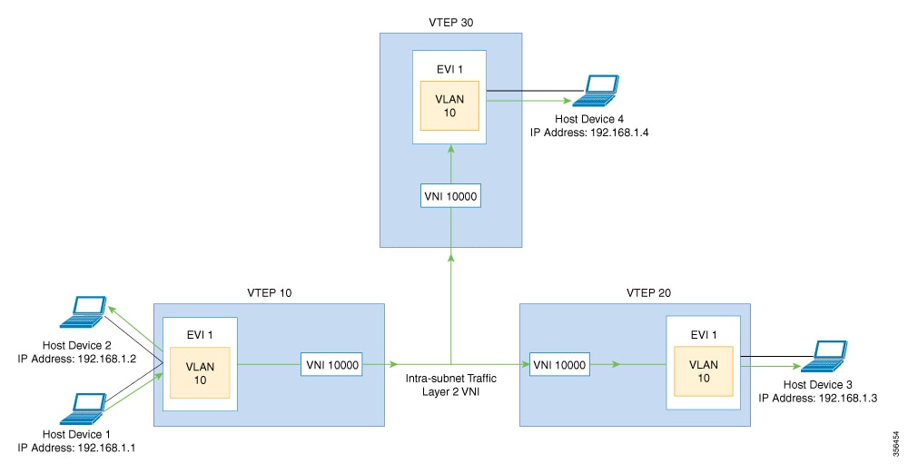
The following image shows the flow of BUM traffic through a Layer 2 VNI. The network forwards BUM traffic from host device 1 to all the VTEPs which in turn send the traffic to all the host devices in the same subnet.

The MP-BGP EVPN control plane uses two different methods to forward BUM traffic in a VXLAN network:

  • Underlay Multicast

  • Ingress Replication

Underlay Multicast

In underlay multicast, the underlay network replicates the traffic through a multicast group. Forwarding BUM traffic using underlay multicast requires the configuration of IP multicast in the underlay network. A single copy of the BUM traffic moves from the ingress or source VTEP towards the underlay transport network. The network forwards this copy along the multicast tree so that it reaches all egress or destination VTEPs participating in the given multicast group. Various branch points in the network replicate the copy as it travels along the multicast tree. The branch points replicate the copy only if the receivers are part of the multicast group associated with the VNI.

BUM traffic forwarding through underlay multicast is achieved by mapping a Layer 2 VNI to the multicast group. This mapping must be configured on all the VTEPs associated with the Layer 2 VNI. When a VTEP joins the multicast group, it receives all the traffic that is forwarded on that group. If the VTEP receives traffic in a VNI that is not associated with it, it simply drops the traffic. This approach maintains a single link within the network, thus providing an efficient way to forward BUM traffic.

Ingress Replication

Ingress replication, or headend replication, is a unicast approach to handle multidestination Layer 2 overlay BUM traffic. Ingress replication involves an ingress device replicating every incoming BUM packet and sending them as a separate unicast to the remote egress devices. Ingress replication happens through EVPN route type 3, also called as inclusive multicast ethernet tag (IMET) route. BGP EVPN ingress replication uses IMET route for auto-discovery of remote peers in order to set up the BUM tunnels over VXLAN. Using ingress replication to handle BUM traffic can result in scaling issues as an ingress device needs to replicate the BUM traffic as many times as there are VTEPs associated with the Layer 2 VNI.

Ingress Replication Operation

IMET routes carry the remote or egress VNIs advertised from the remote peers, which can be different from the local VNI. The network creates a VXLAN tunnel adjacency when an ingress device receives IMET ingress replication routes from remote NVE peers. The tunnel adjacency is a midchain adjacency which contains IP or UDP encapsulation for the VXLAN Tunnel. If there is more than one VNI along the tunnel, then multiple VNIs share the tunnel. Ingress replication on EVPN can have multiple unicast tunnel adjacencies and different egress VNIs for each remote peer.

The network builds a flooded replication list with the routes advertised by each VTEP. The dynamic replication list stores all the remote destination peers discovered on a BGP IMET route in the same Layer 2 VNI. The replication list gets updated every time you configure the Layer 2 VNI at a remote peer. The network removes the tunnel adjacency and VXLAN encapsulation from the replication list every time a remote NVE peer withdraws the IMET ingress replication route. The network deletes the tunnel adjacency when there is no NVE peer using it.

Any BUM traffic that reaches the ingress device gets replicated after the replication list is built. The ingress device forwards the replicated traffic throughout the network to all the remote peers in the same VNI.

Flooding Suppression

EVPN allows the distribution of the binding between IPv4 or IPv6 addresses and MAC addresses among the VTEPs of the network. It distributes the MAC-IP binding among all the VTEPs that participate in the EVPN instance associated with the MAC-IP routes. The MAC address associated with the IPv4 or IPv6 addresses is locally known even though it is learned from a remote VTEP. Locally connected endpoints send an Address Resolution Protocol (ARP) or an IPv6 neighbor discovery request when they look for a remote endpoint. The MAC-IP binding distribution allows a VTEP to perform a lookup in the local cache when it receives an ARP or an IPv6 neighbor discovery request. If the MAC-IP address information for the remote end point is available, the VTEP can use this information to avoid flooding the ARP request. If the MAC or IP address information for the remote end point is not available, the request floods throughout the fabric.

Flooding suppression avoids the flooding of ARP and IPv6 neighbor discovery packets over the EVPN VXLAN network. It suppresses the flooding to both the local and remote host or access devices. The network suppresses the flooding by implementing an ARP or neighbor discovery relay. This is achieved by using the known MAC address for the specified IPv4 or IPv6 address to convert broadcast and multicast requests to unicast requests. Flooding suppression is enabled by default on an EVPN-enabled VLAN. An EVPN VXLAN network suppresses the flooding for the following types of traffic:

ARP Flooding Suppression

VTEPs send ARP requests as broadcast packets. ARP requests represent a large percentage of Layer 2 broadcast traffic. Flooding suppression converts them to unicast packets and reduces the network flood.

IPv6 Neighbor Discovery Flooding Suppression

The IPv6 neighbor discovery process enables the discovery of a neighbor and helps the peers to determine each other's link-layer addresses. It also verifies the reachability of a neighbor and tracks the neighboring routers. IPv6 neighbor discovery uses Internet Control Message Protocol (ICMP) messages and solicited-node multicast addresses to achieve these functions.

Flooding suppression suppresses all multicast neighbor solicitation packets among Internet Control Message Protocol version 6 (ICMPv6) packets.

How to Configure EVPN VXLAN Layer 2 Overlay Network

The following figure shows a sample topology of an EVPN VXLAN Network. Host device 1 and host device 3 are part of the same subnet. The network forwards BUM traffic from host device 1 to host device 3 using a Layer 2 VNI through either underlay multicast or ingress replication methods.


Note

In a two-VTEP topology, a spine switch is not mandatory. For information about configuration of spine switches in an EVPN VXLAN network, see Configuring Spine Switches in a BGP EVPN VXLAN Fabric module.


Perform the following set of procedures to configure an EVPN VXLAN Layer 2 overlay network and forward the BUM traffic:

  • Configure Layer 2 VPN EVPN on the VTEPs.

  • Configure an EVPN instance in the VLAN on the VTEPs.

  • Configure the access-facing interface in the VLAN on the VTEPs.

  • Configure the loopback interface on the VTEPs.

  • Configure the network virtualization endpoint (NVE) interface on the VTEPs.

  • Configure BGP with EVPN address family on the VTEPs.

  • Configure underlay multicast, if the specified replication type is static. For more information, see IP Multicast Routing Configuration Guide.

Configuring Layer 2 VPN EVPN on a VTEP

To configure the Layer 2 VPN EVPN parameters on a VTEP, perform the following steps:

Procedure

  Command or Action Purpose
Step 1

enable

Example:

Device> enable

Enables privileged EXEC mode.

Enter your password, if prompted.

Step 2

configure terminal

Example:

Device# configure terminal

Enters global configuration mode.

Step 3

l2vpn evpn

Example:

Device(config)# l2vpn evpn

Enters EVPN configuration mode.

Step 4

replication-type { ingress | static}

Example:

Device(config-evpn)# replication-type static

Configures the Layer 2 VPN EVPN replication type.

Note 

Configure the Layer 2 VPN EVPN replication type as static, if multicast is enabled in the underlay network for EVPN BUM traffic.

When the Layer 2 VPN EVPN replication type is configured as static, the IMET route is not advertised and forwarding of BUM traffic relies on underlay multicast being configured on each VTEP.

Step 5

router-id loopback-interface-id

Example:

Device(config-evpn)# router-id loopback 0

Specifies the interface that will supply the IP addresses to be used in auto-generating route distinguishers.

Step 6

default-gateway advertise

Example:

Device(config-evpn)# default-gateway advertise

(Optional) Enables default gateway advertisement on the switch. To configure distributed anycast gateway in a VXLAN network using MAC aliasing, enable default gateway advertisement on all the leaf switches in the network.

This command is applicable in integrated routing and bridging (IRB) scenarios where Layer 2 and Layer 3 VNIs coexist in a VRF. Refer to Configuring EVPN VXLAN Integrated Routing and Bridging module for more details.

This command is mandatory only if the same MAC address is not manually configured on all the access SVIs.

Note 

Use the default-gateway advertise { enable | disable} command in EVPN instnace configuration mode to override the global default gateway advertisement settings and enable or disable it for a specific EVPN instance.

Step 7

logging peer state

Example:

Device(config-evpn)# logging peer state

(Optional) Displays syslog message when the first route is received or the last route is withdrawn from a given remote VTEP.

Step 8

mac duplication limit limit-number time time-limit

Example:

Device(config-evpn)# mac duplication limit 20 time 5

(Optional) Changes parameters for detecting duplicate MAC addresses.

Step 9

ip duplication limit limit-number time time-limit

Example:

Device(config-evpn)# ip duplication limit 20 time 5

(Optional) Changes parameters for detecting duplicate IP addresses.

Step 10

route-target auto vni

Example:

Device(config-evpn)# route-target auto vni

(Optional) Specifies to use VNI instead of EVPN instance number to auto-generate route target.

Step 11

exit

Example:

Device(config-evpn)# exit

Exits EVPN configuration mode and enters global configuration mode.

Step 12

l2vpn evpn instance evpn-instance-number vlan-based

Example:

Device(config)# l2vpn evpn instance 1 vlan-based

Configures a VLAN based EVPN instance in Layer 2 VPN configuration mode.

An EVPN instance needs to be explicitly configured only when something needs to be configured per EVPN instance such as a route target.

Step 13

encapsulation vxlan

Example:

Device(config-evpn-evi)# encapsulation vxlan

(Optional) Defines the encapsulation format as VXLAN.

The encapsulation format is VXLAN by default.

Step 14

replication-type { ingress | static}

Example:

Device(config-evpn-evi)# replication-type ingress

(Optional) Sets the replication type for the EVPN instance.

In case a global replication type has already been configured, this overrides the global setting.

Step 15

default-gateway advertise { enable | disable}

Example:

Device(config-evpn-evi)# default-gateway advertise disable

(Optional) Enables or disables the default gateway advertisement for the EVPN instance.

In case default gateway advertisement has already been globally configured, this overrides the global setting.

This command is mandatory only if the same MAC address is not manually configured on all the access SVIs.

To configure distributed anycast gateway in a VXLAN network using MAC aliasing, enable default gateway advertisement on all the leaf switches in the network.

Step 16

ip local-learning { enable | disable}

Example:

Device(config-evpn-evi)# ip local-learning disable

(Optional) Enables or disables local IP address learning for the specified EVPN instance.

In case IP address learning has already been globally configured, this overrides the global setting.

Step 17

no auto-route-target

Example:

Device(config-evpn-evi)# no auto-route-target

(Optional) Disables auto generation of route targets.

Step 18

rd rd-value

Example:

Device(config-evpn-evi)# rd 65000:100

(Optional) Configures a route distinguisher manually.

Step 19

route-target { import | export | both} rt-value

Example:

Device(config-evpn-evi)# route-target both 65000:100

(Optional) Configures route targets manually.

Note 

Configure route targets manually if the auto-generated route target values (ASN:EVI or ASN:VNI) are different between the VTEPs.

Step 20

end

Example:

Device(config-evpn-evi)# end

Returns to privileged EXEC mode.

Configuring an EVPN Instance on the VLAN on a VTEP

To configure an EVPN instance on the VLAN on a VTEP, perform the following steps:

Procedure

  Command or Action Purpose
Step 1

enable

Example:

Device> enable

Enables privileged EXEC mode.

Enter your password, if prompted.

Step 2

configure terminal

Example:

Device# configure terminal

Enters global configuration mode.

Step 3

vlan configuration vlan-id

Example:

Device(config)# vlan configuration 11

Enters VLAN feature configuration mode for the specified VLAN interface.

Step 4

member evpn-instance evpn-instance-id vni l2-vni-number

Example:

Device(config-vlan)# member evpn-instance 1 vni 10000

Adds EVPN instance as a member of the VLAN configuration.

The VNI here is used as a Layer 2 VNI.

Step 5

end

Example:

Device(config-vlan)# end

Returns to privileged EXEC mode.

Configuring the Loopback Interface on a VTEP

To configure the loopback interface on a VTEP, perform the following steps:

Procedure

  Command or Action Purpose
Step 1

enable

Example:

Device> enable

Enables privileged EXEC mode.

Enter your password, if prompted.

Step 2

configure terminal

Example:

Device# configure terminal

Enters global configuration mode.

Step 3

interface loopback-interface-id

Example:

Device(config)# interface Loopback0

Enters interface configuration mode for the specified Loopback interface.

Step 4

ip address ipv4-address

Example:

Device(config-if)# ip address 10.12.11.11

Configures the IP address for the Loopback interface.

Step 5

ip pim sparse mode

Example:

Device(config-if)# ip pim sparse mode

Enables Protocol Independent Multicast (PIM) sparse mode on the Loopback interface.

Step 6

end

Example:

Device(config-vlan)# end

Returns to privileged EXEC mode.

Configuring the Access-Facing Interface in the VLAN on a VTEP

To configure the access-facing interface in the VLAN on a VTEP, perform the following steps:

Procedure

  Command or Action Purpose
Step 1

enable

Example:

Device> enable

Enables privileged EXEC mode.

Enter your password, if prompted.

Step 2

configure terminal

Example:

Device# configure terminal

Enters global configuration mode.

Step 3

interface interface-name

Example:

Device(config)# interface GigabitEthernet1/0/1

Enters interface configuration mode for the specified interface.

Step 4

switchport access vlan vlan-id

Example:

Device(config-if)# switchport access vlan 11

Configures the interface as a static-access port of the specified VLAN.

Interface can also be configured as a trunk interface, if required.

Step 5

end

Example:

Device(config-if)# end

Returns to privileged EXEC mode.

Configuring the NVE Interface on a VTEP

To add a VNI member to the NVE interface of a VTEP, perform the following steps:

Procedure

  Command or Action Purpose
Step 1

enable

Example:

Device> enable

Enables privileged EXEC mode.

Enter your password, if prompted.

Step 2

configure terminal

Example:

Device# configure terminal

Enters global configuration mode.

Step 3

interface nve-interface-id

Example:

Device(config)# interface nve1

Defines the interface to be configured as a trunk, and enters interface configuration mode.

Step 4

no ip address

Example:

Device(config-if)# no ip address

Disables IP processing on the interface by removing its IP address.

Step 5

source-interface loopback-interface-id

Example:

Device(config-if)# source-interface loopback0

Sets the IP address of the specified loopback interface as the source IP address.

Step 6

host-reachability protocol bgp

Example:

Device(config-if)# host-reachability protocol bgp

Configures BGP as the host-reachability protocol on the interface.

Step 7

member vni layer2-vni-id { ingress-replication | mcast-group multicast-group-address

Example:

Device(config-if)# member vni 10000 mcast-group 227.0.0.1

Associates the Layer 2 VNI member with the NVE.

The specified replication type must match the replication type that is configured globally or for the specific EVPN instance. Use mcast-group keyword for static replication and ingress-replication keyword for ingress replication.

Step 8

end

Example:

Device(config-if)# end

Returns to privileged EXEC mode.

Configuring BGP on a VTEP with EVPN Address Family

To configure BGP on a VTEP with EVPN address family and with spine switch as the neighbor, perform the following steps:

Procedure

  Command or Action Purpose
Step 1

enable

Example:

Device> enable

Enables privileged EXEC mode.

Enter your password, if prompted.

Step 2

configure terminal

Example:

Device# configure terminal

Enters global configuration mode.

Step 3

router bgp autonomous-system-number

Example:

Device(config)# router bgp 1

Enables a BGP routing process, assigns it an autonomous system number, and enters router configuration mode.

Step 4

bgp log-neighbor-changes

Example:

Device(config-router)# bgp log-neighbor-changes

(Optional) Enables the generation of logging messages when the status of a BGP neighbor changes.

For more information, see Configuring BGP module of the IP Routing Configuration Guide.

Step 5

bgp update-delay time-period

Example:

Device(config-router)# bgp update-delay 1

(Optional) Sets the maximum initial delay period before sending the first update.

The range is 1 to 3600 seconds.

For more information, see Configuring BGP module of the IP Routing Configuration Guide.

Step 6

bgp graceful-restart

Example:

Device(config-router)# bgp graceful-restart

(Optional) Enables the BGP graceful restart capability for all BGP neighbors.

For more information, see Configuring BGP module of the IP Routing Configuration Guide.

Step 7

no bgp default ipv4-unicast

Example:

Device(config-router)# no bgp default ipv4-unicast

(Optional) Disables default IPv4 unicast address family for BGP peering session establishment.

For more information, see Configuring BGP module of the IP Routing Configuration Guide.

Step 8

neighbor ip-address remote-as number

Example:

Device(config-router)# neighbor 10.11.11.11 remote-as 1

Defines multiprotocol-BGP neighbors. Under each neighbor, define the Layer 2 Virtual Private Network (L2VPN) EVPN configuration.

Use the IP address of the spine switch as the neighbor IP address.

Step 9

neighbor { ip-address | group-name} update-source interface

Example:

Device(config-router)# neighbor 10.11.11.11 update-source Loopback0

Configures update source. Update source can be configured per neighbor or per peer-group.

Use the IP address of the spine switch as the neighbor IP address.

Step 10

address-family l2vpn evpn

Example:

Device(config-router)# address-family l2vpn evpn

Specifies the L2VPN address family and enters address family configuration mode.

Step 11

neighbor ip-address activate

Example:

Device(config-router-af)# neighbor 10.11.11.11 activate

Enables the exchange information from a BGP neighbor.

Use the IP address of the spine switch as the neighbor IP address.

Step 12

neighbor ip-address send-community [ both | extended | standard]

Example:

Device(config-router-af)# neighbor 10.11.11.11 send-community both

Specifies the communities attribute sent to a BGP neighbor.

Use the IP address of the spine switch as the neighbor IP address.

Step 13

exit-address-family

Example:

Device(config-router-af)# exit-address-family

Exits address family configuration mode and returns to router configuration mode.

Step 14

end

Example:

Device(config-router)# end

Returns to privileged EXEC mode.

Configuration Examples for EVPN VXLAN Layer 2 Overlay Network

This section provides an example for configuring an EVPN VXLAN Layer 2 overlay network. This example shows a sample configuration for a VXLAN network with 2 VTEPs, VTEP 1 and VTEP 2, connected to perform bridging.


Note

In a two-VTEP topology, a spine switch is not mandatory. For information about configuration of spine switches in an EVPN VXLAN network, see Configuring Spine Switches in a BGP EVPN VXLAN Fabric module.


Table 1. Configuration Example for a VXLAN Network with Two VTEPs Connected to Perform Bridging

VTEP 1

VTEP 2

VTEP1# show running-config
Building configuration...
!
hostname VTEP1
!
ip routing
ip multicast-routing
!
l2vpn evpn
 replication-type static
 router-id Loopback0
!
l2vpn evpn instance 1 vlan-based
 encapsulation vxlan
 route-target export 103:1
 route-target import 104:1
!
system mtu 9150
!
vlan configuration 201
 member evpn-instance 1 vni 6000
!
!
interface Loopback0
 ip address 10.1.1.10 255.255.255.255
 ip pim sparse-mode
!
!
interface GigabitEthernet1/0/1
description host1-interface
 switchport access vlan 201
 switchport mode access
!
!
interface GigabitEthernet1/0/29
 description core-underlay-interface
 no switchport
ip address 172.16.1.29 255.255.255.0
 ip pim sparse-mode
!
!
interface nve10
 no ip address
 source-interface Loopback0
 host-reachability protocol bgp
 member vni 6000 mcast-group 232.1.1.1
!
router ospf 1
 router-id 10.1.1.10
 network 10.1.1.0 0.0.0.255 area 0
 network 172.16.1.0 0.0.0.255 area 0
!
router bgp 10
 bgp router-id interface Loopback0
 bgp log-neighbor-changes
 bgp update-delay 1
 no bgp default ipv4-unicast
 neighbor 10.2.2.20 remote-as 10
 neighbor 10.2.2.20 update-source Loopback0
 !
 address-family ipv4
 exit-address-family
 !
 address-family l2vpn evpn
  neighbor 10.2.2.20 activate
  neighbor 10.2.2.20 send-community both
 exit-address-family
 !
ip pim rp-address 10.1.1.10
!
end

VTEP2# show running-config
Building configuration...
!
hostname VTEP2
!
ip routing
ip multicast-routing
!
l2vpn evpn
 replication-type static
 router-id Loopback0
!
l2vpn evpn instance 1 vlan-based
 encapsulation vxlan
 route-target export 104:1
 route-target import 103:1
!
system mtu 9150
!
vlan configuration 201
 member evpn-instance 1 vni 6000
!
!
interface Loopback0
 ip address 10.2.2.20 255.255.255.255
 ip pim sparse-mode
!
!
interface GigabitEthernet1/0/1
description host2-interface
 switchport access vlan 201
 switchport mode access
!
!
interface GigabitEthernet1/0/30
 description core-underlay-interface
 no switchport
 ip address 172.16.1.30 255.255.255.0
 ip pim sparse-mode
!
!
interface nve10
 no ip address
 source-interface Loopback0
 host-reachability protocol bgp
 member vni 6000 mcast-group 232.1.1.1
!
router ospf 1
 router-id 10.2.2.20
 network 10.2.2.0 0.0.0.255 area 0
 network 172.16.1.0 0.0.0.255 area 0
!
router bgp 10
 bgp router-id interface Loopback0
 bgp log-neighbor-changes
 bgp update-delay 1
 no bgp default ipv4-unicast
 neighbor 10.1.1.10 remote-as 10
 neighbor 10.1.1.10 update-source Loopback0
 !
 address-family ipv4
 exit-address-family
 !
 address-family l2vpn evpn
  neighbor 10.1.1.10 activate
  neighbor 10.1.1.10 send-community both
 exit-address-family
!
ip pim rp-address 10.1.1.10
!
end

The following examples provide outputs for show commands on VTEP 1 and VTEP 2 in the topology configured above.

show l2vpn evpn peers vxlan

VTEP 1

This example shows the output for the show l2vpn evpn peers vxlan command on VTEP 1:

VTEP1# show l2vpn evpn peers vxlan
Interface VNI      Peer-IP                   Num routes eVNI     UP time
--------- -------- ------------------------  ---------- -------- --------
nve10     6000     10.2.2.20                 3          6000     00:12:44

VTEP 2

This example shows the output for the show l2vpn evpn peers vxlan command on VTEP 2:

VTEP2# show l2vpn evpn peers vxlan
Interface VNI      Peer-IP                   Num routes eVNI     UP time
--------- -------- ------------------------  ---------- -------- --------
nve10     6000     10.1.1.10                 3          6000     00:01:41

show nve peers

VTEP 1

This example shows the output for the show nve peers command on VTEP 1:

VTEP1# show nve peers
Interface  VNI      Type Peer-IP          RMAC/Num_RTs   eVNI     state flags UP time
nve10      6000     L2CP 10.2.2.20        3              6000       UP   N/A  00:12:48

VTEP 2

This example shows the output for the show nve peers command on VTEP 2:

VTEP2# show nve peers
Interface  VNI      Type Peer-IP          RMAC/Num_RTs   eVNI     state flags UP time
nve10      6000     L2CP 10.1.1.10        3              6000       UP   N/A  00:01:46

show l2vpn evpn mac

VTEP 1

This example shows the output for the show l2vpn evpn mac command on VTEP 1:

VTEP1# show l2vpn evpn mac
MAC Address    EVI   VLAN  ESI                      Ether Tag  Next Hop(s)
-------------- ----- ----- ------------------------ ---------- ---------------
0018.736c.5681 1     201   0000.0000.0000.0000.0000 0          10.2.2.20
0018.736c.56c3 1     201   0000.0000.0000.0000.0000 0          10.2.2.20
0059.dc50.ae01 1     201   0000.0000.0000.0000.0000 0          Gi1/0/1:201
0059.dc50.ae4c 1     201   0000.0000.0000.0000.0000 0          Gi1/0/1:201

VTEP 2

This example shows the output for the show l2vpn evpn mac command on VTEP 2:

VTEP2# show l2vpn evpn mac
MAC Address    EVI   VLAN  ESI                      Ether Tag  Next Hop(s)
-------------- ----- ----- ------------------------ ---------- ---------------
0018.736c.5681 1     201   0000.0000.0000.0000.0000 0          Gi1/0/1:201
0018.736c.56c3 1     201   0000.0000.0000.0000.0000 0          Gi1/0/1:201
0059.dc50.ae01 1     201   0000.0000.0000.0000.0000 0          10.1.1.10
0059.dc50.ae4c 1     201   0000.0000.0000.0000.0000 0          10.1.1.10

show bgp l2vpn evpn all

VTEP 1

This example shows the output for the show bgp l2vpn evpn all command on VTEP 1:

VTEP1# show bgp l2vpn evpn all
BGP table version is 101, local router ID is 10.1.1.10
Status codes: s suppressed, d damped, h history, * valid, > best, i - internal,
              r RIB-failure, S Stale, m multipath, b backup-path, f RT-Filter,
              x best-external, a additional-path, c RIB-compressed,
              t secondary path, L long-lived-stale,
Origin codes: i - IGP, e - EGP, ? - incomplete
RPKI validation codes: V valid, I invalid, N Not found

     Network          Next Hop            Metric LocPrf Weight Path
Route Distinguisher: 10.1.1.10:1
 *>i  [2][10.1.1.10:1][0][48][0018736C5681][0][*]/20
                      10.2.2.20                0    100      0 ?
 *>i  [2][10.1.1.10:1][0][48][0018736C56C3][0][*]/20
                      10.2.2.20                0    100      0 ?
 *>i  [2][10.1.1.10:1][0][48][0018736C56C3][32][192.168.1.89]/24
                      10.2.2.20                0    100      0 ?
 *>   [2][10.1.1.10:1][0][48][0059DC50AE01][0][*]/20
                      ::                                 32768 ?
 *>   [2][10.1.1.10:1][0][48][0059DC50AE4C][0][*]/20
                      ::                                 32768 ?
 *>   [2][10.1.1.10:1][0][48][0059DC50AE4C][32][192.168.1.81]/24
                      ::                                 32768 ?
Route Distinguisher: 10.2.2.20:1
 *>i  [2][10.2.2.20:1][0][48][0018736C5681][0][*]/20
                      10.2.2.20                0    100      0 ?
 *>i  [2][10.2.2.20:1][0][48][0018736C56C3][0][*]/20
                      10.2.2.20                0    100      0 ?
 *>i  [2][10.2.2.20:1][0][48][0018736C56C3][32][192.168.1.89]/24
                      10.2.2.20                0    100      0 ?

VTEP 2

This example shows the output for the show bgp l2vpn evpn all command on VTEP 2:

VTEP2# show bgp l2vpn evpn all
BGP table version is 99, local router ID is 10.2.2.20
Status codes: s suppressed, d damped, h history, * valid, > best, i - internal,
              r RIB-failure, S Stale, m multipath, b backup-path, f RT-Filter,
              x best-external, a additional-path, c RIB-compressed,
              t secondary path, L long-lived-stale,
Origin codes: i - IGP, e - EGP, ? - incomplete
RPKI validation codes: V valid, I invalid, N Not found
     Network          Next Hop            Metric LocPrf Weight Path
Route Distinguisher: 10.1.1.10:1
 *>i  [2][10.1.1.10:1][0][48][0059DC50AE01][0][*]/20
                      10.1.1.10                0    100      0 ?
 *>i  [2][10.1.1.10:1][0][48][0059DC50AE4C][0][*]/20
                      10.1.1.10                0    100      0 ?
 *>i  [2][10.1.1.10:1][0][48][0059DC50AE4C][32][192.168.1.81]/24
                      10.1.1.10                0    100      0 ?
Route Distinguisher: 10.2.2.20:1
 *>   [2][10.2.2.20:1][0][48][0018736C5681][0][*]/20
                      ::                                 32768 ?
 *>   [2][10.2.2.20:1][0][48][0018736C56C3][0][*]/20
                      ::                                 32768 ?
 *>   [2][10.2.2.20:1][0][48][0018736C56C3][32][192.168.1.89]/24
     Network          Next Hop            Metric LocPrf Weight Path
                      ::                                 32768 ?
 *>i  [2][10.2.2.20:1][0][48][0059DC50AE01][0][*]/20
                      10.1.1.10                0    100      0 ?
 *>i  [2][10.2.2.20:1][0][48][0059DC50AE4C][0][*]/20
                      10.1.1.10                0    100      0 ?
 *>i  [2][10.2.2.20:1][0][48][0059DC50AE4C][32][192.168.1.81]/24
                      10.1.1.10                0    100      0 ?

show platform software fed switch active matm macTable vlan

VTEP 1

This example shows the output for the show platform software fed switch active matm mactable vlan command on VTEP 1:

VTEP1# show platform software fed switch active matm macTable vlan 201
VLAN   MAC                   Type  Seq#   EC_Bi  Flags  machandle           siHandle            riHandle            diHandle              *a_time  *e_time  ports                           
------------------------------------------------------------------------------------------------------------------------------------------------------------------------------------------
201    0018.736c.5681   0x1000001      0      0     64  0x7f5d852abaf8      0x7f5d850c1858      0x7f5d8527def8      0x0                         0        0  RLOC 10.2.2.20 adj_id 81        
201    0018.736c.56c3   0x1000001      0      0     64  0x7f5d855be2b8      0x7f5d850c1858      0x7f5d8527def8      0x0                         0        0  RLOC 10.2.2.20 adj_id 81        
201    0059.dc50.ae01         0x1     22      0      0  0x7f5d855c6388      0x7f5d85035248      0x0                 0x7f5d8517eae8            300       11  GigabitEthernet1/0/1            
201    0059.dc50.ae4c         0x1     26      0      0  0x7f5d84fba3c8      0x7f5d85035248      0x0                 0x7f5d8517eae8            300       58  GigabitEthernet1/0/1            

Total Mac number of addresses:: 4

VTEP 2

This example shows the output for the show platform software fed switch active matm mactable vlan command on VTEP 2:

VTEP2# show platform software fed switch active matm macTable vlan 201
VLAN   MAC                   Type  Seq#   EC_Bi  Flags  machandle           siHandle            riHandle            diHandle              *a_time  *e_time  ports                           
------------------------------------------------------------------------------------------------------------------------------------------------------------------------------------------
201    0018.736c.5681         0x1     38      0      0  0x7f40e196cac8      0x7f40e196cf28      0x0                 0x7f40e0f6da38            300       12  GigabitEthernet1/0/1            
201    0018.736c.56c3         0x1     39      0      0  0x7f40e19b6878      0x7f40e196cf28      0x0                 0x7f40e0f6da38            300       17  GigabitEthernet1/0/1            
201    0059.dc50.ae01   0x1000001      0      0     64  0x7f40e19b88f8      0x7f40e1937b88      0x7f40e193bd58      0x0                         0       17  RLOC 10.1.1.10 adj_id 28        
201    0059.dc50.ae4c   0x1000001      0      0     64  0x7f40e194d638      0x7f40e1937b88      0x7f40e193bd58      0x0                         0       17  RLOC 10.1.1.10 adj_id 28        

Total Mac number of addresses:: 4

Verifying EVPN VXLAN Layer 2 Overlay Network

The following table lists the show commands that are used to verify a Layer 2 VXLAN overlay network:

Table 2. Commands to Verify EVPN VXLAN Layer 2 Overlay Network

Command

Purpose

show l2vpn evpn evi [ detail]

Displays detailed information for a particular EVPN instance or all EVPN instances.

show l2vpn evpn mac [ detail]

Displays the MAC address database for Layer 2 EVPN.

show l2vpn evpn mac ip [ detail]

Displays the IP address database for Layer 2 EVPN.

show l2vpn evpn summary

Displays a summary of Layer 2 EVPN information.

show l2vpn evpn capabilities

Displays platform capability information for Layer 2 EVPN.

show l2vpn evpn peers

Displays Layer 2 EVPN peer route counts and up time.

show l2vpn evpn route-target

Displays Layer 2 EVPN import route targets.

show l2vpn evpn memory

Displays Layer 2 EVPN memory usage.

show l2route evpn summary

Displays a summary of EVPN routes.

show l2route evpn mac [ detail]

Displays MAC address information learnt by the switch in the EVPN control plane.

show l2route evpn mac ip [ detail]

Displays MAC and IP address information learnt by the switch in the EVPN control plane.

show l2route evpn imet detail

Displays the IMET route details for Layer 2 EVPN address family.

This command shows details only about traffic forwarded using ingress replication.

show bgp l2vpn evpn

Displays BGP information for Layer 2 VPN EVPN address family.

show bgp l2vpn evpn route-type 2

Displays BGP information for route type 2 of L2VPN EVPN address family.

show bgp l2vpn evpn evi context

Displays context information for Layer 2 EVPN instances.

show bgp l2vpn evpn evi evpn-instance-id route-type 3

Displays route type 3 information for the specified Layer 2 EVPN instance.

This command shows details only about traffic forwarded using ingress replication.

show l2fib bridge-domain bridge-domain-number detail

Displays detailed information for a Layer 2 forwarding information base bridge domain.

show l2fib bridge-domain bridge-domain-number address unicast

Displays unicast MAC address information for a Layer 2 forwarding information base bridge domain.

show nve vni

Displays information about VXLAN network identifier members associated with an NVE interface.

show nve vni vni-id detail

Displays detailed NVE interface state information for a VXLAN network identifier member.

show nve peers

Displays NVE interface state information for peer leaf switches.

show mac address-table vlan vlan-id

Displays MAC addresses for a VLAN.

show platform software fed switch active matm macTable vlan vlan-id

Displays MAC addresses for a VLAN from MAC address table manager database for Forwarding Engine Driver (FED).

show device-tracking database

Displays device tracking database.

show device-tracking database mac

Displays device tracking MAC address database.

show ip mroute

Displays multicast routing table information.