Stateful Firewall on Cisco Catalyst 9300 Series Switches

Stateful Firewall on Cisco Catalyst 9300 Series Switches

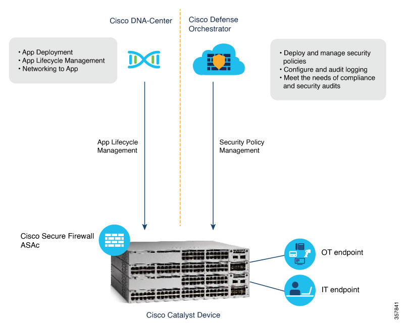
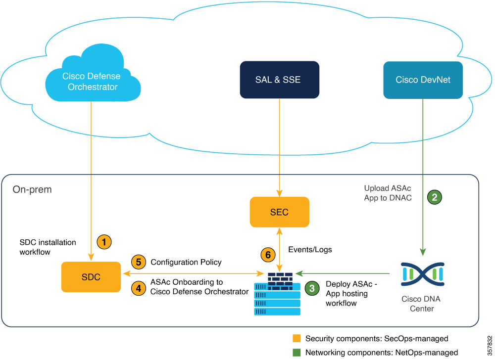
Application hosting on Cisco Catalyst 9300 Series Switches is integrated with the Cisco Adaptive Security Virtual Appliance (ASAc) for the stateful inspection of traffic in a network without changing the network architecture. The app-hosting infrastructure on these Catalyst switches can seamlessly add the ASAc instances to the existing network by using USB SSD to host ASAc on Cisco Catalyst 9300 Series Switches.

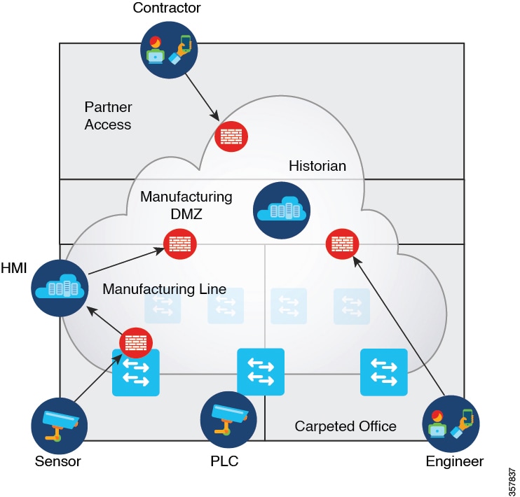
Previously, operational technology (OT) systems were isolated from external networks, making them less vulnerable to cyber threats. With Industry 4.0, digital transformation and smart manufacturing have accelerated the convergence of information technology (IT) and OT networks in the process industry. While this integration can bring significant benefits, such as, increased efficiency, improved visibility, and better decision-making, it can also increase the risk of cyberattacks.

IoT (Internet of Things) devices and sensors are proliferating into IT networks, and these devices are managed under a single IT network infrastructure to build smarter and safer work spaces. However; these IoT devices introduce several security threats to IT networks because these devices often have limited processing power and memory, making it challenging to implement robust security features, and most of these devices are not up to date on security updates. Attackers exploit these vulnerabilities to pivot from compromised IoT devices to critical systems and data.

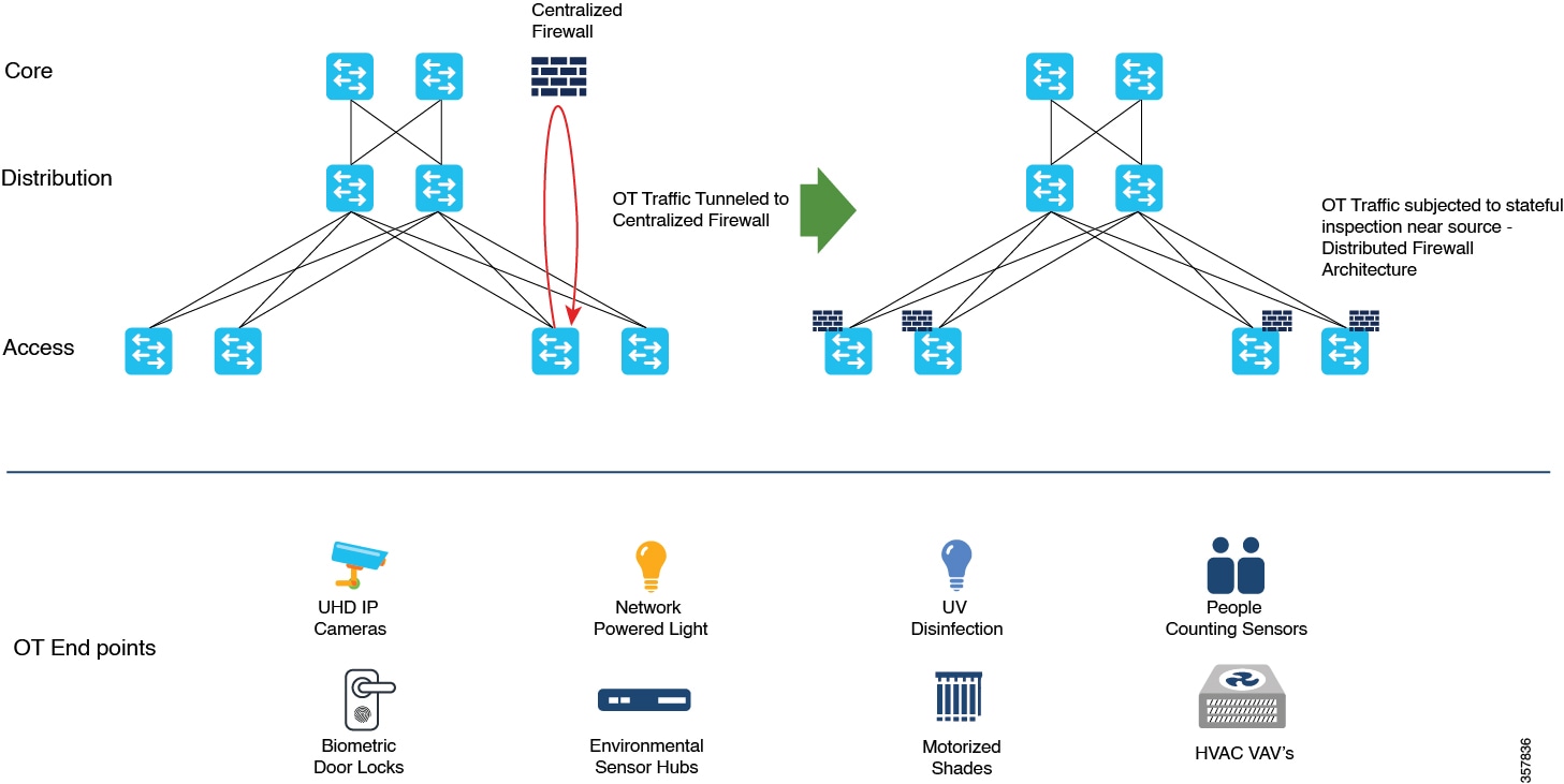
By hosting the containerized Secure Firewall ASA on Catalyst 9300 Series Switches, organizations can benefit from enhanced security and simplified network deployment. This solution not only reduces the complexity of steering the traffic to centralized firewalls using complex tunnels, but also eliminates the need for additional hardware.

Positioning the firewall services nearer to the source provides a cost-effective and highly efficient way of securing IT-OT converged networks. It also minimizes the latency for time-sensitive SOS applications, by enforcing the policies near the source, where the devices connect to the network.

The redundant links and power supplies of the Catalyst 9300 Series Switches are leveraged by the virtual firewall instances that are hosted on these switches, thereby reducing the need for additional servers and physical firewall appliances, saving on rack space, cooling requirements, and operational costs.

By leveraging these capabilities, organizations can simplify their network design, reduce costs, and improve their security posture.

Capabilities of the Stateful Firewall Solution

The Stateful Firewall solution provides the following capabilities:


Note


The ASAc firewall that is hosted on Catalyst 9300 Series Switches is a containerized form of ASAv. It has features parity with ASAv with few exceptions.


  • Powerful stateful inspection firewall.

  • Layer 3 and Layer 4 firewall policies.

  • Support for Security Group Tags (SGTs).

  • Separation of the security operations (SecOps) and network operations (NetOps) at the network level.

  • Routed mode (Layer 3) firewall

  • Transport Encryption with IPsec tunnels

  • Secure Remote Management with VPN

The Stateful Firewall solution supports up to:

  • 10 logical interfaces

  • 900Mbps of firewall throughput (450-byte packet) with C9300X (4vCPUs/8GB RAM)

  • 500Mbps of firewall throughput (450-byte packet) with C9300 (2vCPUs/2GB RAM)

  • 250 IPsec VPN tunnels

  • 8000 connections per session

The integration of ASAc on Cisco Catalyst 9300 Series Switches simplifies the network design by providing the flexibility to plug in small-form factor firewalls in the network closer to the source. This design lowers the total cost of ownership by reducing the number of physical firewall appliances in the network.

The Stateful Firewall AppHosting solution hosts a virtual firewall or ASAc on Cisco Catalyst 9300 Series Switches. All the physical firewalls next to a switch can be virtualized and deployed on the switch itself. As in a traditional network, the SecOps manage the ASAc firewalls that is deployed on the Catalyst switches, and the NetOps teams instantiate the application and perform lifecycle management using the Cisco Catalyst Center (formerly known as Digital Network Architecture [DNA] Center). The SecOps team controls policy management using the Cisco Defense Orchestrator. Both the SecOps and NetOps teams can seamlessly manage the network without any disruptions.

Prerequisites for the Stateful Firewall Solution

The following prerequisites apply to this solution:

  • Cisco Catalyst 9300, 9300L, 9300LM, or 9300X Series Switches are up and running.

  • Cisco pluggable USB 3.0 SSD-120G or SSD-240G storage is available.

  • Cisco Catalyst or DNA-Advantage subscription license is available.

  • Cisco ASAc Subscription license L-ASA-V-5S-K9= or L-ASA-V-10S-K9= is available.

    One of the following ASAc license is required:

    • ASAc5 (L-ASA-C-5S-K9=) - 1 Core-License (100M)

    • ASAc10 (L-ASA-C-10S-K9=) - 2 Core-License (1G)

    • ASAv5 (L-ASA-V-5S-K9=) - 1 Core-License (100M

    • ASAv10 (L-ASA-V-10S-K9=) - 2 Core-License (1G)

  • ASAc supports two types of licenses: ASAc Smart License and ASAc Permanent License Reservation (PLR) mode. You can use either the existing ASAv5/ASAv10 license or a new ASAc5/ASAc10 license.

  • The Cisco Catalyst Center application-hosting workflow expects that VLANs are created on the switch before these VLANs are allowed on the AppGigabitEthernet Interface.

  • The minimum resources required to host ASAc are 1vCPU, 2GB RAM, and 40GB free disk space.

  • Cisco Catalyst Center is recommended to automate the ASAc lifecycle management at scale.

  • Cisco Defense Orchestrator is recommended for ASAc security policy management and event logging at scale.

Restrictions for the Stateful Firewall Solution

The following restrictions apply to this solution:

  • Transparent mode is not supported on ASAc firewall when hosted on Catalyst 9300 Series Switches; only routed mode is supported.

  • On-premises management of ASAc instances with Cisco Security Manager is not supported.

  • Jumbo frames are not supported.

  • Stateful high availability is not supported. However, IOx synchronizes the ASAc application configuration data every 15 minutes to the standby device.

    • After a failover, ASAc on the standby device boots up with the configuration that is copied from the old active device.

    • It takes around 90 seconds for ASAc on the new active device to start sending and receiving traffic.

    ASAc supports stateless high availability on the Catalyst 9300 switch stack. It takes around 90 to 120 seconds for ASAc on the standby to start processing the traffic after a failover.

  • No other application can be hosted on Catalyst 9300, 9300L, and 9300LM Series Switches when ASAc is hosted.

    Catalyst 9300X Series Switches can host another application, like ThousandEves, along with ASAc; however, the performance of these two applications may vary when both are run simultaneously.

  • The ASAc interface IP configs and day0 configurations should be passed as files in the Cisco Catalyst Center application hosting workflow. The ASAc interface IP configurations in Cisco Catalyst Center Ul will be ignored.

  • ASAc clustering is not supported.

Components of the Solution

The following illustration displays the components of the solution:

Cisco Defense Orchestrator

Cisco Defense Orchestrator is a cloud-based management solution that allows you to centrally manage security policies and device configurations across multiple Cisco products that include Cisco Adaptive Security Appliance (ASA), both on-premises and virtual.

The Cisco Defense Orchestrator deploys and manages security policies, meets the needs of compliance and security audits, and logs configuration and audit messages. The Cisco Defense Orchestrator helps optimize your security policies by identifying inconsistencies and providing tools to fix these issues. You can share objects and policies, and create configuration templates, to promote policy consistency across devices using the Cisco Defense Orchestrator.

A per-device license is required for the Cisco Defense Orchestrator.

For more information about the Cisco Defense Orchestrator, see the following links:

Cisco Catalyst Center

Cisco Catalyst Center is a set of software solutions that manage your network devices and automate your services. The NetOps team uses the Cisco Catalyst Center to install the ASAc application, transfer the Day 0 configuration for network connectivity, manage the lifecycle of the ASAc application hosting, and upgrade the ASAc versions.

Cisco Adaptive Security Virtual Appliance

The container-version of the Cisco ASA (ASAc) provides full firewall functionality to secure IT, OT, and IoT converged networks. ASAc uses Layer 3 firewall policies and does a stateful inspection of the traffic.

In this solution, ASAc runs on a 240G external Solid State Drive (SSD) that is mounted on a Cisco Catalyst switch. Cisco Catalyst Center deploys the ASAc on these Catalyst switches, and ASAc is then onboarded to the Cisco Defense Orchestrator for security policy management.

For more information, see Managing ASA with Cisco Defense Orchestrator.

Supported Platforms

This section lists the supported platforms:

  • Cisco Catalyst 9300, 9300L, 9300LM, and 9300X Series Switches

Solution Requirements

The following table describes the supported release version for the software, and the hardware required for the stateful firewall solution:

Table 1. Supported Release Version

Component

Release

Cisco ASAc

9.20.2 or later

Cisco Catalyst 9300, 9300L, 9300LM, and 9300X Series Switches

Cisco IOS XE Dublin 17.12.2 or later release

Cisco Defense Orchestrator

Cloud Base (latest version)

Cisco Catalyst Center Appliance

44 or 56 cores

Cisco Catalyst Center Platform

2.3.7.0 or later

Cisco Identity Services Engine (ISE)

3.1

Software License

  • C9300 Catalyst or DNA Advantage license (C9300-DNA-A)

  • L-ASA-C-5S-K9=: Cisco ASAc License PID

    • L-ASA-C-5S-1Y

    • L-ASA-C-5S-3Y

    • L-ASA-C-5S-5Y

  • L-ASA-C-10S-K9=: Cisco ASAc License PID

    • L-ASA-C-10S-1Y

    • L-ASA-C-10S-3Y

    • L-ASA-C-10S-5Y

  • Licenses required on Cisco Defense Orchestrator to manage ASAc instances are:

    • Cisco Defense Orchestrator Base license (CDO-SEC-SUB)

    • Cisco Defense Orchestrator license to manage ASAc (L-ASAV-P=)

    Note


    Cisco Defense Orchestrator is optional.

External Solid State Drive (SSD)

Cisco SSD-240G: Cisco Catalyst 9300, 9300L, 9300LM and 9300X Series Switches

Note


Cisco does not ship Cisco SSD-120G; however, existing devices that have Cisco SSD-120G, can use it for ASAc apphosting.

High-Level Workflow

This section provides a high-level workflow of how the ASAc application is installed and security policies are managed at scale for large deployments using Cisco Catalyst Center and Cisco Defence Orchestrator.

High-level workflow of ASAv/ASAc Firewall Solution
  1. The user installs SDC and SEC on premises, and bootstraps both of these with the Cisco Defense Orchestrator.

  2. Cisco Catalyst Center installs the ASAc on the Cisco Catalyst Center appliance by using YANG models or app-hosting CLIs.

  3. The user uploads the ASAc application, Day 0 configuration, and the ASAc interface configuration including the interface IP addresses on to the Cisco Catalyst Center.

  4. Cisco Catalyst Center deploys the ASAc application on Catalyst 9300 Series Switches.


    Note


    Cisco Catalyst Center can scale to multiple access switches and deploy them simultaneously.


  5. After the ASAc is deployed, it is onboarded to the Cisco Defense Orchestrator manually.

  6. After all the ASAcs are onboarded, the Cisco Defense Orchestrator applies common policies and configuration to the ASAcs.

  7. Events are collected through the SEC for compliance and reporting.

In smaller deployment scenarios, for example, a deployment with only 10 Catalyst switches, you can use YANG models or Cisco IOS CLIs to deploy the ASAcs on Cisco Catalyst switches. For smaller deployments, to manage the ASAc security policy, we recommend that you use the Adaptive Security Device Manager (ASDM), which is a Web UI that is bundled in the ASAc container package.

Use Case 1

The illustration below displays a deployment scenario with distributed firewalls hosted on access switches to minimize latency and eliminate the need for complex tunnels.

For security compliance, the OT or IOT traffic is tunneled to a centralized firewall for policy enforcement. The distributed firewall architecture simplifies the network design, and increases the network performance by enforcing the firewall policy at the IT-OT convergence points.

Figure 1. Use Case 1


Use Case 2

In the following illustration, you can see a factory that has different zones, and to cross over, these zones require a firewall. This means that the factory must have the same number of physical firewalls as the number of switches deployed in the network in order to inspect traffic between different zones and groups of users. Both the firewalls and switches need physical power redundancy, and redundant link management. To allow user mobility (for example, an engineer from the carpeted space coming into the factory floor), firewalls will have to be placed at multiple locations.

The Cisco Catalyst 9300 Series Switches provide application hosting capabilities that easily combines the physical firewall with the virtual container available on the switch. By using the ASAc firewall hosted on the Cisco Catalyst 9300 Series Switches, the factory can be easily maintained and operated without compromising on security.

Figure 2. Use Case 2


Use Case 3

In an airport ecosystem, various vendors share a common network. Baggage management system is one of the critical systems in this network. The baggage management system regulates the operation of the baggage conveyor belts through Programmable Logic Controllers (PLCs) that are distributed across airport terminals, often separated by vast distances.

The complex network in between incorporates numerous network devices, making the security of the baggage management system traffic a primary concern. To address this issue, IPSec tunnels are created between the ASAc instances hosted on the Catalyst 9300 Series Switches connecting the baggage management system and PLC, to provide a secure passage for the baggage traffic, and reduce the risk of data breaches.

The ASAc allows different vendors to create their own IPSec tunnels, offering flexibility and control over their traffic in a shared network. This ensures the efficient operation of critical systems while maintaining the security and integrity of the network.

The illustration below is an IPSec usecase that shows how to securely connect the IT-OT network clusters, and encrypt the OT traffic passing through the shared IT network:

IPSec Usecase for ASAc

Use Case 4

This use case elaborates on the importance and effectiveness of using the ASAc hosted on Catalyst 9300 Series Switches for the secure remote management of operational cameras in a manufacturing environment. Within the manufacturing sector, operational cameras play a pivotal role in monitoring critical processes continuously. These cameras, directly connected to Catalyst 9300 Series Switches, can be remotely accessed by the operators. This remote access is made secure by establishing VPN tunnels to the ASAc hosted on the Catalyst 9300 Series Switches.

How to Configure the Solution

This section describes how to configure all the components of the Stateful Firewall solution.


Note


We assume that the following devices are already installed and working in the network:

  • A Cisco device (Cisco Catalyst 9300, 9300L, 9300LM, or 9300X)

  • Cisco Catalyst Center

  • Cisco Adaptive Security Device Manager (ASDM)


Installing SSD and Enabling Cisco IOx

Procedure


Step 1

Install the Solid State Drive (SSD).

  1. On stackable switches, it is recommended to have the SSD installed on both the preferred active and standby devices.

  2. For more information, see Installing a USB 3.0 SSD.

Step 2

Format the SSD.

  1. For more information, see Formatting USB 3.0 SSD.

Step 3

Use the iox command in global configuration mode, to enable Cisco IOx on the device.

  1. Save the configuration.

Step 4

Use the show iox command to verify that the Cisco IOx services are running:

Device# show iox 

IOx Infrastructure Summary:
---------------------------
IOx service (CAF)              : Running
IOx service (HA)               : Running
IOx service (IOxman)           : Running
IOx service (Sec storage)      : Running
Libvirtd 5.5.0                 : Running
Dockerd v19.03.13-ce           : Running
Sync Status                    : Disabled
 

Step 5

Use the show app-hosting infra command to verify the application hosting infrastructure mounted on the SSD:

Device# show app-hosting infra

IOX version: 2.8.0.0
App signature verification: enabled
CAF Health: Stable
Internal working directory: /vol/usb1/iox
 
Application Interface Mapping
AppGigabitEthernet Port #  Interface Name                 Port Type            Bandwidth
           1               AppGigabitEthernet1/0/1        KR Port - Internal   1G
 
 
CPU:
  Quota: 25(Percentage)
  Available: 25(Percentage)
  Quota: 7400(Units)
  Available: 7400(Units)


Enabling Application Hosting


Note


DNA-Advantage license on Cisco Catalyst 9300 Series Switch is required for application hosting.


SUMMARY STEPS

  1. enable
  2. configure terminal
  3. interface AppGigabitEthernet number
  4. switchport trunk allowed vlan vlan-ID
  5. switchport mode trunk
  6. exit
  7. app-hosting appid application-name
  8. app-vnic AppGigabitEthernet port port_number trunk
  9. app-vnic management guest-interface guest-interface-number
  10. vlan vlan-ID guest-interface guest-interface-number
  11. end

DETAILED STEPS

  Command or Action Purpose

Step 1

enable

Example:

Device> enable

Enables privileged EXEC mode.

Enter your password if prompted.

Step 2

configure terminal

Example:

Device# configure terminal

Enters global configuration mode.

Step 3

interface AppGigabitEthernet number

Example:

Device(config)# interface AppGigabitEthernet 1/0/1

Configures the AppGigabitEthernet and enters interface configuration mode.

For stackable switches, the number argument is switch-number/0/1.

Step 4

switchport trunk allowed vlan vlan-ID

Example:

Device(config-if)# switchport trunk allowed vlan 10-12,20

Configures the list of VLANs allowed on the trunk.

Step 5

switchport mode trunk

Example:

Device(config-if)# switchport mode trunk

Sets the interface into permanent trunking mode and negotiates to convert the neighboring link into a trunk link.

Step 6

exit

Example:

Device(config-if)# exit

Exits interface configuration mode and returns to global configuration mode.

Step 7

app-hosting appid application-name

Example:

Device(config)# app-hosting appid asac_app

Configures an application and enters application-hosting configuration mode.

Step 8

app-vnic AppGigabitEthernet port port_number trunk

Example:

Device(config-app-hosting)# app-vnic AppGigabitEthernet port 1 trunk 

Configures a trunk port as the front-panel port for an application, and enters application-hosting trunk-configuration mode.

The port_number can be configured as:
  • 1: On the 9300, 9300L, and 9300LM switches as only one AppGigabitEthernet interfaces is present.

  • 1 or 2: On the 9300X switches, there are two AppGigabitEthernet interfaces. You can configure 1 or 2 based on the usage of the interface.

Step 9

app-vnic management guest-interface guest-interface-number

Example:

Device(config-config-app-hosting-trunk)# app-vnic management guest-interface 0

Configures the management interface. Management interface should be always configured as guest-interface 0.

Note


Configuring the management interface on any other VLAN is not supported.

Step 10

vlan vlan-ID guest-interface guest-interface-number

Example:

Device(config-config-app-hosting-trunk)# vlan 10
guest-interface 1
Device(config-config-app-hosting-trunk)# vlan 11
guest-interface 2

Configures the VLAN-to-guest interface mappings.

The guest-interface-number must be configured as:

  • 1: For inside VLAN

  • 2: For outside VLAN

Note


Up to 10 logical interfaces can be configured including the management interface.

Step 11

end

Example:

Device(config-config-app-hosting-vlan-access-ip)# end

Exits application-hosting VLAN-access IP configuration mode and returns to privileged EXEC mode.

Files Shared with ASAc

This section describes the files that the Cisco devices (Cisco Catalyst 9300/9300L/9300LM/9300X Series Switches) share with the ASAc.

The interface-config and day0-config files are shared with the ASAc. Both these files must be created on the Cisco device in the specified folder with the specified contents, and the file names must be interface-config and day0-config.

  • On the Catalyst device, create the interface-configuration file (interface-config) in the usbflash1:iox_host_data_share folder.

    This folder is shared between the Cisco device and ASAc. In case this file is missing, ASAc will not be able to detect any Network Interface Cards (NICs) and will not boot up. This file must specify the three interfaces and the drivers that are used to operate these interfaces. Only the afpacket driver is compatible with ASAc.

    On ASAc, the interface-config file must be available in the /mnt/disk0/interface-config folder. To share the file, use the following command when configuring docker options:
    run-opts 3 "-v /usbflash1:/iox_host_data_share/:/mnt/disk0/interface-config"

    The following is a sample of an interface-config file:

    
    	[interface0]
    	iface_id = eth0;
    	uio_driver = afpacket;
    	[interface1]
    	iface_id = eth1;
    	uio_driver = afpacket;
    	[interface2]
    	iface_id = eth2;
    	uio_driver = afpacket;
    
    
  • Day-Zero configuration file (day0-config) must be created in the usbflash1:iox_host_data_share folder. This folder is shared between the Catalyst device and ASAc.

    The following is a sample of a day0-config file:

    
    	interface management 0/0
    	 nameif management
    	 ip address dhcp setroute
    	 security-level 100
    	 no shutdown
    	 username admin password password1
    	 aaa authentication ssh console LOCAL
    	 aaa authentication http console LOCAL
    	 aaa authentication telnet console LOCAL
    	 ssh 0.0.0.0 0.0.0.0 management
    	 no ssh stack ciscossh
    	 telnet 0.0.0.0 0.0.0.0 management
    	 http server enable
    	 http 0.0.0.0 0.0.0.0 management
    	 crypto key generate rsa modulus 2048


    Note


    To enable a Secure Shell (SSH) connection to the ASAc management IP, the no ssh stack ciscossh command must be available in the day0 configuration file.


    Note


    Any files that must be retained during deactivation or activation of the ASAc must be copied to the disk0:/interface-config/ folder that is mapped to usbflash1:/iox_host_data_share/ folder on the Catalyst switch. Files that reside outside of the disk0:/interface-config/ folder are cleared during the deactivation or activation of the ASAc.


ASAc Interface Mapping

The following table displays the mapping between Catalyst switch guest interfaces and corresponding ASAc interfaces:

Table 2. Mapping Between Catalyst Switch Guest Interfaces and Corresponding ASAc Interfaces

guest-interface

ASAc Interface

eth0 (guest-interface 0)

Management 0/0

eth1 (guest-interface 1)

GigabitEthernet 0/0

eth2 (guest-interface 2)

GigabitEthernet 0/1

eth3 (guest-interface 3)

GigabitEthernet 0/2

eth4 (guest-interface 4)

GigabitEthernet 0/3

eth5 (guest-interface 5)

GigabitEthernet 0/4

eth6 (guest-interface 6)

GigabitEthernet 0/5

eth7 (guest-interface 7)

GigabitEthernet 0/6

eth8 (guest-interface 8)

GigabitEthernet 0/7

eth9 (guest-interface 9)

GigabitEthernet 0/8

Configuring the App Resource Docker Profile

For app hosting resource changes to take effect, you must first stop and deactivate an app using the app-hosting stop and app-hosting deactivate commands, and then restart the app using the app-hosting activate and app-hosting start commands.

If you are using the start command in application-hosting configuration mode, configure the no start and start commands.


Note


Additional CPU and memory can be allocated on Cisco Catalyst switches. For optimal performance, we recommend that you use:

  • 2vCPU and 2GB memory on Catalyst 9300 Series Switches

  • 4vCPU and 8GB memory on Catalyst 9300X Series Switches


SUMMARY STEPS

  1. enable
  2. configure terminal
  3. app-hosting appid application-name
  4. app-resource docker
  5. run-opts options
  6. run-opts options
  7. run-opts options
  8. end

DETAILED STEPS

  Command or Action Purpose

Step 1

enable

Example:

Device> enable

Enables privileged EXEC mode.

Enter your password if prompted.

Step 2

configure terminal

Example:

Device# configure terminal

Enters global configuration mode.

Step 3

app-hosting appid application-name

Example:

Device(config)# app-hosting appid asac_app

Configures an application and enters application-hosting configuration mode.

Step 4

app-resource docker

Example:

Device(config-app-hosting)# app-resource docker

Configures the docker custom application and enters custom application resource profile configuration mode.

Step 5

run-opts options

Example:

Device(config-app-hosting-docker)# run-opts 2 
"--cap-add=NET_ADMIN --device=/dev/net/tun:/dev/net/tun"

Configures the capability to run the docker container.

In this step, the run-opts command configures the following:

  • Enables the NET_ADMIN capability as part of the docker options.

  • Creates the device files when the container boots up (/dev/net/tun).

Note


By default, to run a docker container on a Catalyst device requires non-privileged (non-root) access rights.

Step 6

run-opts options

Example:

Device(config-app-hosting-docker)# run-opts 3 "-v /usbflash1:/iox_host_data_share/:/mnt/disk0/interface-config 
-v /usbflash1:/iox_host_data_share:/asac-day0-config"

Configures the path of the interface-config and day0-config (startup configuration) files.

Step 7

run-opts options

Example:

Device(config-app-hosting-docker)# run-opts 4 "-e ASAC_MEMORY=2048M -e ASAC_CPUS=2 -e ASA_DOCKER=1 -e ASAC_CAT9K=1 -e \
ASAC_DEALER_ENDPOINT=localhost:5555" 

Sets the environment variables required to run the ASAc container, and the core-file size limit for storing crash logs.

Note


For 4vCPU and 8GB memory on Catalyst 9300X series switches, pass the below options:

  • ASAC_MEMORY=8192M

  • ASAC_CPUS=4

Step 8

end

Example:

Device(config-app-hosting-docker)# end

Exits custom application resource profile configuration mode and returns to privileged EXEC mode.

Installing and Running the ASAc Application

SUMMARY STEPS

  1. enable
  2. app-hosting install appid application-name package package-path
  3. app-hosting activate appid application-name
  4. app-hosting start appid application-name
  5. app-hosting connect appid application-name session
  6. exit

DETAILED STEPS

  Command or Action Purpose

Step 1

enable

Example:

Device> enable

Enables privileged EXEC mode.

Enter your password, if prompted.

Step 2

app-hosting install appid application-name package package-path

Example:

Device# app-hosting install appid asac_app package usbflash1:ASAc-9.18.2.150-app-SPA.tar

Installs the ASAc application from the specified location.

Step 3

app-hosting activate appid application-name

Example:

Device# app-hosting activate appid asac_app

asac_app activated successfully 
Current state is: ACTIVATED

Activates the application.

This command validates all the application resource requests, and if all the resources are available, the application is activated; if not, the activation fails.

Step 4

app-hosting start appid application-name

Example:

Device# app-hosting start appid asac_app

asac_app started successfully 
Current state is: RUNNING

Starts the application.

Application start-up scripts are activated.

Step 5

app-hosting connect appid application-name session

Example:

Device# app-hosting connect appid asac_app session

Connects to the ASAc CLI session.

Step 6

exit

Example:

Device# exit

Exits privileged EXEC mode and returns to user EXEC mode.

Connecting to the ASAc Console

To connect to the ASAc console from Catalyst 9300 Series Switches, perform this procedure:

SUMMARY STEPS

  1. enable
  2. app-hosting connect appid application-name session
  3. lina_cli

DETAILED STEPS

  Command or Action Purpose

Step 1

enable

Example:

Device> enable

Enables privileged EXEC mode.

  • Enter your password if prompted.

Step 2

app-hosting connect appid application-name session

Example:

Device# app-hosting connect appid asac_app session

Connects to the ASAc docker container shell.

Step 3

lina_cli

Example:

sh-5.1# lina_cli

Connects to the ASAc console.

Note


To detach from the ASAc console, perform these steps:

  1. Press the Ctrl key + A key.

  2. Press the D key.

  3. Exits the ASAc console and enters the Catalyst switch prompt.

Upgrading the ASAc Application

To upgrade the ASAc application, use the app-hosting upgrade appid application-name package usbflash0: package-name command.

During the upgrade, the ASAc application goes through the following states:
running > stopped > deployed > uninstall > deployed > activated > running
.

Installing ASAc through Cisco Catalyst Center

To install ASAc through Catalyst Center, perform this procedure:

Before you begin

  • The Cisco Catalyst 9300 Series switch must be on-boarded on Cisco Catalyst Center.

  • The ASAc app must be uploaded on the Cisco Catalyst Center.

  • Interface and Day 0 configuration files should be named as interface-config and day0-config respectively without any extension.

Procedure


Step 1

On the Cisco Catalyst Center, configure the ASAc interfaces using the Configure App tab.

  1. Enter the interface name in the Interface Name field.

  2. Select the Address Type as Dynamic.

Note


Adding static IP addresses in the Configure App menu is not supported.

The interface configuration of the ASAc including the IP addresses should be passed as a Day 0 configuration (day0-config) file.

Step 2

Upload the interface and Day 0 configuration files using the Upload App Data button.

Step 3

To upgrade ASAc to the latest version,

  1. Upload the new ASAc package to the Cisco Catalyst Center.

  2. Select the Upgrade App button in the ASAc Manage tab.

The app goes through the following states while upgrading:

Running > Stopped > Deployed > Uninstalled & removed > Deployed > Activated > Running

Note


The upgrade package version should be higher than the running ASAc package version. For downgrading, ASAc must be uninstalled and installed again.


Deploying a Secure Device Connector

When using device credentials to connect the Cisco Defense Orchestrator to a device, it is a best practice to download and deploy an SDC in your network to manage the communication between the Cisco Defense Orchestrator and the device. Typically, these devices are nonperimeter-based, do not have a public IP address, or have an open port to the outside interface. An ASAc can be on-boarded to the Cisco Defense Orchestrator using an SDC.

For more information on deploying a Secure Device Connector, see https://docs.defenseorchestrator.com/t_deploy-a-sdc-using-cdos-vm-image.html.

Setting the ASAc Container Management IP Address

You can configure the IP address of the management network of an ASAc by using the following methods:


Note


The ASAc management IP address should be in the same network of the Catalyst switch management network.


  • Static IP configuration:

    ASAc static IP address can be passed through the Day 0 configuration file. Alternatively, it can be configured through the ASAc console manually.

    To connect to the ASAc console, perform this procedure:

    1. Use the app-hosting connect appid application-name session command to connect to the ASAc docker container shell.
      Device# app-hosting connect appid asac_app session
    2. Use the lina_cli to connect to the ASAc console.
      sh-5.1# lina_cli
  • Dynamic IP Configuration:

    For dynamic IP, configure DHCP in the ASAc Day 0 configuration file. Include ip address dhcp setroute in the Day 0 configuration file for configuring the DHCP in the management interface.

Accessing the ASAc Core Files

If the ASAc crashes, you can access the core file, available in the usbflash1:/iox_host_data_share/ directory on the Cisco Catalyst 9300 Series Switches as displayed in the following example:

Device# dir usbflash1:iox_host_data_share

Directory of usbflash1:/iox_host_data_share/
4194311  -rw-              158  Aug 30 2023 07:03:52 +00:00  interface-config
4194323  -rw-                2  Aug 30 2023 05:43:59 +00:00  num_restarts
4194319  -rw-         88762999  Aug 30 2023 05:43:54 +00:00  7d8c57b49014_lina_440_20230123-095208-UTC.core.gz

You can export ASAc core file from the Catalyst 9300 device by using the copy command as displayed in the following example:

Device# copy usbflash1:/iox_host_data_share/<core file> scp:

You can view the ASAc core files in the disk0:interface-config folder as displayed in the following example:

ciscoasa# dir disk0:interface-config 

4194324  -rw-  95894782     12:21:39 Nov 01 2023  ee3a29cb9f63_lina_383_20231101-122117-UTC.core.gz

Collecting ASAc Log Files

You can access the ASAc driver Data Plane Development Kit (DPDK) logs from the following location:

ciscoasa# dir disk0:dpdk.log

Directory of disk0:/dpdk.log
3165668  -rw-  10521        06:54:36 Oct 16 2023  dpdk.log
1 file(s) total size: 10521 bytes
117951578112 bytes total (108889157632 bytes free/92% free

If ASAc is not accessible from the Catalyst switch, you can connect to the ASAc container shell and connect the logs as displayed in the following example:


Device# app-hosting connect appid asac_app session
sh-5.1# ls /var/log/lina_console.log  -l

-rw-r--r-- 1 root root 30836 Oct 16 06:53 /var/log/lina_console.log
sh-5.1# ls -l /mnt/disk0/dpdk.log 
-rw------- 1 root root 3628 Oct 30 10:07 /mnt/disk0/dpdk.log

Accessing the ASAc Configuration Files

The following example shows how to access the interface-config configuration file:

ciscoasa# dir disk0:interface-config/interface-config

Directory of disk0:/interface-config/interface-config
4194311  -rw-  158          07:03:52 Aug 30 2023  interface-config
1 file(s) total size: 158 bytes
117951578112 bytes total (108889169920 bytes free/92% free)

The following example shows how to access the day0-config configuration file:

ciscoasa# dir disk0:interface-config/day0-config  
   
Directory of disk0:/interface-config/day0-config
4194317  -rw-  2174         12:30:25 Aug 10 2023  day0-config
1 file(s) total size: 2174 bytes
117951578112 bytes total (108889169920 bytes free/92% free)

If ASAc is not accessible, config files can be accessed by connecting to the ASAc container shell as shown in the example below:

sh-5.1# ls -l /mnt/disk0/interface-config/
-rw-r--r-- 1 nobody nogroup     2174 Aug 10 12:30 day0-config
-rw-r--r-- 1 nobody nogroup      158 Aug 30 07:03 interface-config

Verifying the Configuration on a Cisco Catalyst 9300 Series Switch

The following sample output displays shows the apps running on a Cisco Catalyst 9300 Series Switch:

Device# show app-hosting list 

App id                                   State
---------------------------------------------------------
asac_app                                 RUNNING

The following sample output displays the IOx services:


Note


If the IOx service is not enabled, you must enable it using the iox command in global configuration mode.

Device# show iox

IOx Infrastructure Summary:
---------------------------
IOx service (CAF)              : Running
IOx service (HA)               : Running 
IOx service (IOxman)           : Running 
IOx service (Sec storage)      : Running 
Libvirtd 5.5.0                 : Running
Dockerd v19.03.13-ce           : Running
Sync Status                    : Disabled


The following sample output displays the apphosting infra details:

Device# show app-hosting infra 

IOX version: 2.11.0.0
App signature verification: disabled
CAF Health: Stable
Internal working directory: /vol/usb1/iox

Application Interface Mapping
AppGigabitEthernet Port #  Interface Name                 Port Type            Bandwidth  
           1               AppGigabitEthernet1/0/1        KR Port - Internal   10G
       
           2               AppGigabitEthernet1/0/2        KR Port - Internal   10G
       

CPU:
  Quota: 25(Percentage) 
  Available: 0(Percentage)
  Quota: 7400(Units)
  Available: 0(Units)

The following sample output displays the running-configuration on the AppGigabitEthernet interface:

Device# show running-config interface AppGigabitEthernet 1/0/1

Building configuration...

Current configuration : 156 bytes
!
interface AppGigabitEthernet1/0/1
 switchport trunk allowed vlan 1,10-20
 switchport mode trunk
 mtu 2048
end


The following example shows how to add VLANs to the AppGigabitEthernet interface:

Device> enable
Device# configure terminal
Enter configuration commands, one per line.  End with CNTL/Z.
Device(config)# interface appGigabitEthernet 1/0/1
Device(config-if)# switchport trunk allowed vlan 21,23
Device(config-if)# end

You can also use the show tech-support command to collect common data from commands such as show version, and also debugging information.


Note


However; running the show tech-support command will stop the application temporarily. By rebooting the Catalyst switch, the application will resume activity.


Verifying the Configuration on the ASAc

You can use the show tech-support command to display the information that is used for diagnosis by technical support analysts. The output of the command also displays all show commands and their output:

ciscoasa# show tech-support


Note


The show tech-support command lets you list information that technical support analysts need to help you diagnose problems. This command combines the output from the show commands that provide the most information to a technical support analyst.


The following sample output displays brief information about the interfaces:

ciscoasa# show interface ip brief 

Interface                  IP-Address      OK? Method Status                Protocol
GigabitEthernet0/0         10.1.1.1        YES CONFIG up                    up  
GigabitEthernet0/1         192.0.2.1       YES CONFIG up                    up  
Internal-Data0/0           192.168.0.4     YES unset  up                    up  
Management0/0              172.16.0.2      YES CONFIG up                    up 

The following sample output displays information regarding the traffic drops in ASAc:

ciscoasa# show asp drop 

Frame drop:
  Interface is down (interface-down)                                           3
Last clearing: Never
Flow drop:
Last clearing: Never

The following sample output displays statistics information:

ciscoasa# show controller
 
Management0/0:
   DPDK Statistics
                  rx_good_packets : 6226555
                  tx_good_packets : 49277
                    rx_good_bytes : 703290932
                    tx_good_bytes : 24249530
                 rx_missed_errors : 0
                        rx_errors : 0
                        tx_errors : 0
        rx_mbuf_allocation_errors : 0
                    rx_q0_packets : 6226555
                      rx_q0_bytes : 703290932
                     rx_q0_errors : 0
                    tx_q0_packets : 49277
                      tx_q0_bytes : 24249530
GigabitEthernet0/0:
   DPDK Statistics
.
.
.

Auto-Restarting ASAc

This section describes how to auto-restart the ASAc after a crash.

ASAc application package contains a health script that runs at regular intervals, and starts the firewall application if it is not already running. The health script performs the following operations every five seconds:

  • Check the application health.

  • If the application is having issues, check for the core files, and move these to the folder that is shared between the Cisco device and ASAc. This folder also contains the day0-configuration and interface-configuration files.

  • Record the total number of restarts in the file named num_restarts that is stored in the /asac-day0-config/ directory in ASAc.

  • Restart the ASAc firewall application.

To verify the auto-restart capability, you can force the ASAc to crash, by using the following command:
 ciscoasa# crashinfo force watchdog 

After the crash, once the core file is available in the shared directory, and the num_restarts file is updated, the ASAc firewall application is restarted; and it can be accessed by using the same management IP address that was used prior to the crash.