-
null
- Safety Warnings
- Tools and Equipment
- Installation Guidelines
- Verifying Switch Operation
- Planning and Installing a Switch Stack (Optional)
- Installing the Switch
- Connecting FlexStack-Plus modules (Optional)
- Installing the Power Cord Retainer (Optional)
- Installing SFP Modules
- Connecting to SFP and SFP+ Modules
- 10/100/1000 PoE and PoE+Port Connections
- 10/100/1000 Port Connections
- Where to Go Next
Switch Installation
Safety Warnings
This section includes the basic installation caution and warning statements. Read this section before you start the installation procedure. Translations of the warning statements appear in the RCSI guide on Cisco.com.
 Warning | Before working on equipment that is connected to power lines, remove jewelry (including rings, necklaces, and watches). Metal objects will heat up when connected to power and ground and can cause serious burns or weld the metal object to the terminals. Statement 43 |
Warning | Do not stack the chassis on any other equipment. If the chassis falls, it can cause severe bodily injury and equipment damage. Statement 48 |
Warning | This product must be connected to a power-over-ethernet (PoE) IEEE 802.3af compliant power source or an IEC60950 compliant limited power source. Statement 353 |
Warning | Read the wall-mounting instructions carefully before beginning installation. Failure to use the correct hardware or to follow the correct procedures could result in a hazardous situation to people and damage to the system. Statement 378 |
Warning | Attach only the following Cisco external power system to the switch: PWR-RPS2300 Statement 387 |
Warning | Do not work on the system or connect or disconnect cables during periods of lightning activity. Statement 1001 |
Warning | Read the installation instructions before connecting the system to the power source. Statement 1004 |
Warning |
Warning | Class 1 laser product. Statement 1008 |
Warning | This unit is intended for installation in restricted access areas. A restricted access area can be accessed only through the use of a special tool, lock and key, or other means of security. Statement 1017 |
Warning | The plug-socket combination must be accessible at all times, because it serves as the main disconnecting device. Statement 1019 |
Warning | This equipment must be grounded. Never defeat the ground conductor or operate the equipment in the absence of a suitably installed ground conductor. Contact the appropriate electrical inspection authority or an electrician if you are uncertain that suitable grounding is available. Statement 1024 |
Warning | This unit might have more than one power supply connection. All connections must be removed to de-energize the unit. Statement 1028 |
Warning | Only trained and qualified personnel should be allowed to install, replace, or service this equipment. Statement 1030 |
Warning | Ultimate disposal of this product should be handled according to all national laws and regulations. Statement 1040 |
Warning | For connections outside the building where the equipment is installed, the following ports must be connected through an approved network termination unit with integral circuit protection: 10/100/1000 Ethernet. Statement 1044 |
Warning | When installing or replacing the unit, the ground connection must always be made first and disconnected last. Statement 1046 |
Warning | To prevent the system from overheating, do not operate it in an area that exceeds the maximum recommended ambient temperature of: <113°F (45°C). Statement 1047 |
Warning | This warning symbol means danger. You are in a situation that could cause bodily injury. Before you work on any equipment, be aware of the hazards involved with electrical circuitry and be familiar with standard practices for preventing accidents. Use the statement number provided at the end of each warning to locate its translation in the translated safety warnings that accompanied this device. Statement 1071 |
Warning | Voltages that present a shock hazard may exist on Power over Ethernet (PoE) circuits if interconnections are made using uninsulated exposed metal contacts, conductors, or terminals. Avoid using such interconnection methods, unless the exposed metal parts are located within a restricted access location and users and service people who are authorized within the restricted access location are made aware of the hazard. A restricted access area can be accessed only through the use of a special tool, lock and key or other means of security. Statement 1072 |
Warning | No user-serviceable parts inside. Do not open. Statement 1073 |
Warning | Installation of the equipment must comply with local and national electrical codes. Statement 1074 |
Warning | To prevent airflow restriction, allow clearance around the ventilation openings to be at least: 3 inches (7.6 cm). Statement 1076 |
Warning | Hot surface. Statement 1079 |
Tools and Equipment
Installation Guidelines
When determining where to install the switch, verify that these guidelines are met:
-
Clearance to the switch front and rear panel meets these conditions:
-
Cabling is away from sources of electrical noise, such as radios, power lines, and fluorescent lighting fixtures. Make sure that the cabling is safely away from other devices that might damage the cables.
-
Airflow around the switch and through the vents is unrestricted.
-
Temperature around the unit does not exceed 113°F (45°C). If the switch is installed in a closed or multirack assembly, the temperature around it might be greater than normal room temperature.
-
Altitude at the installation site is not greater than 10,000 feet.
-
For 10/100/1000 fixed ports, the cable length from a switch to a connected device cannot exceed 328 feet (100 meters).
-
Cooling mechanisms, such as fans and blowers in the switch, can draw dust and other particles causing contaminant buildup inside the chassis, which can result in system malfunction. You must install this equipment in an environment as free from dust and foreign conductive material (such as metal flakes from construction activities) as is possible.
Verifying Switch Operation
Before you install the switch in a rack, on a wall, or on a table or shelf, power on the switch and verify that it passes POST.
To power on the switch, plug one end of the AC power cord into the switch AC power connector, and plug the other end into an AC power outlet.
As the switch powers on, it begins the POST, a series of tests that runs automatically to ensure that the switch functions properly. LEDs can blink during the test. POST lasts approximately 1 minute. The SYST LED blinks green, and the other LEDs remain solid green.
When the switch completes POST successfully, the SYST LED remains green. The RPS LED remains green for some time and then reflects the switch operating status. The other LEDs turn off and then reflect the switch operating status. If a switch fails POST, the SYST LED turns amber.
POST failures are usually fatal. Call Cisco technical support representative if your switch fails POST.
After a successful POST, unplug the power cord from the switch and install the switch in a rack, on a wall, on a table, or on a shelf.
If your configuration has an RPS, connect the switch and the RPS to different AC power sources. See the Cisco RPS documentation for information.
 Note | When you connect the RPS to the switch, put the RPS in standby mode. Set the RPS to active mode during normal operation. |
Warning | Attach only the following Cisco external power system to the switch: Cisco XPS 2200 Statement 387 |
Planning and Installing a Switch Stack (Optional)
Stack Guidelines
Stack Cabling
Stacking using FlexStack-Plus Modules
Stacking using FlexStack-Extended Modules
This section explains the supported stacking topologies using FlexStack-Extended Modules.
The following topology is created by stacking switches with FlexStack-Extended Fiber modules that are deployed across different floors of a building. The SFP+ module ports are connected using fiber cables.
The following topology is created by stacking switches with FlexStack-Extended Fiber modules that are deployed across multiple buildings of a campus and different floors of a building.
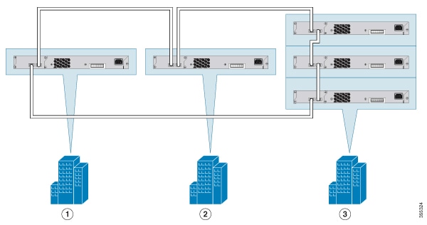
Using FlexStack-Extended Hybrid module, you can combine existing stack of switches and new switches spread across multiple wiring closets into one single stack. To achieve this, the copper port on the FlexStack-Extended Hybrid module should be connected to the FlexStack-Plus port on a switch in your existing network. The fiber port on the Cisco FlexStack-Extended Fiber module can be used to connect switches over long distances. You can stack up to eight switches.
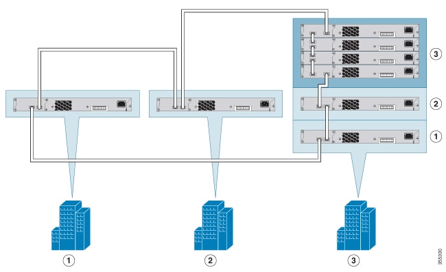
The following image shows a mixed stack network using FlexStack-Plus, FlexStack-Extended Fiber and Hybrid modules. This is one of the supported topologies using FlexStack modules. Typically, fiber modules are used to extend a network for long distance communication across buildings or floors in a building.
Stack Bandwidth and Partitioning Examples
Power-On Sequence for Switch Stacks
Consider these guidelines before you power on the switches in a stack:
The sequence in which the switches are first powered on might affect the switch that becomes the stack master.
If you want a particular switch to be the stack master, power on that switch first. This switch becomes the stack master and remains the stack master until a master reelection. After 2 minutes, power on the other stack switches.
If you have no preference as to which switch becomes the stack master, power on all the switches in the stack within a 1-minute timeframe. These switches participate in the stack master election. Switches powered on after the 1-minute timeframe do not participate in the election.
Power off a switch before you add it to or remove it from an existing switch stack.
For conditions that can cause a stack master reelection or to manually elect the stack master, see the Catalyst 2960-X Switch Stacking Configuration Guide on Cisco.com.
Installing the Switch
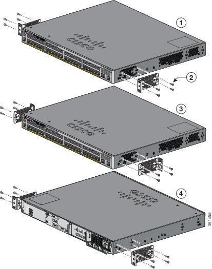
Rack-Mounting
Installation in other than 19-inch racks requires a bracket kit not included with the switch.
Warning |
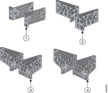
4 |
24-inch brackets |
Attaching the Rack-Mount Brackets
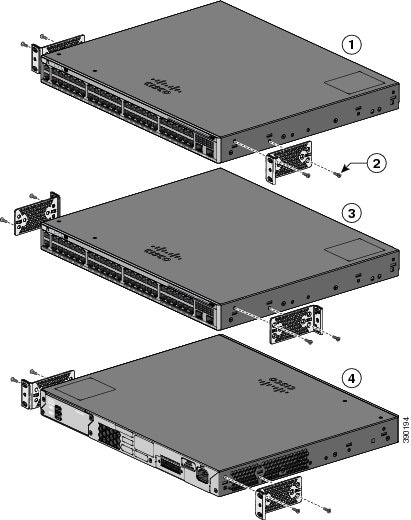
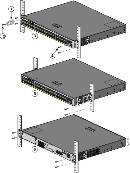
Mounting in a Rack
Wall-Mounting
Warning | Read the wall-mounting instructions carefully before beginning installation. Failure to use the correct hardware or to follow the correct procedures could result in a hazardous situation to people and damage to the system. Statement 378 |
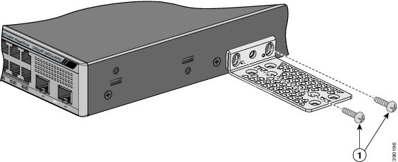
Attaching the Brackets for Wall-Mounting
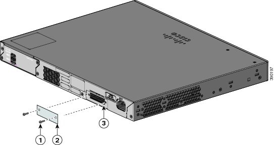
Attaching the RPS Connector Cover
Warning | If an RPS is not connected to the switch, install an RPS connector cover on the back of the switch. Statement 265 |
|
Mounting on a Wall
For the best support of the switch and cables, make sure that the switch is attached securely to wall studs or to a firmly attached plywood-mounting backboard. Mount the switch with the front panel facing down.
Warning | Read the wall-mounting instructions carefully before beginning installation. Failure to use the correct hardware or to follow the correct procedures could result in a hazardous situation to people and damage to the system. Statement 378 |
 Caution | Following safety regulations, wall-mount the switch with its front panel facing down. |
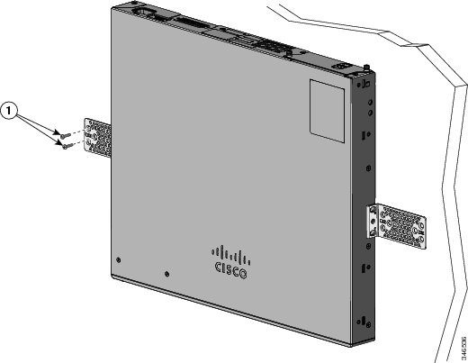
User-supplied screws (for example, you can use # 6 wood screws with a washer head 1-inch long). |
When you complete the switch installation, see After Switch Installation for information on switch configuration.
Installing the Switch on a Table or Shelf
| Step 1 | To install the switch on a table or shelf, locate the adhesive strip with the rubber feet in the mounting-kit envelope. |
| Step 2 | Attach the four rubber feet to the four circular etches on the bottom of the chassis. |
| Step 3 | Place the switch on the table or shelf near an AC power source. |
| Step 4 | When you complete the switch installation, see After Switch Installationfor information on switch configuration. |
After Switch Installation
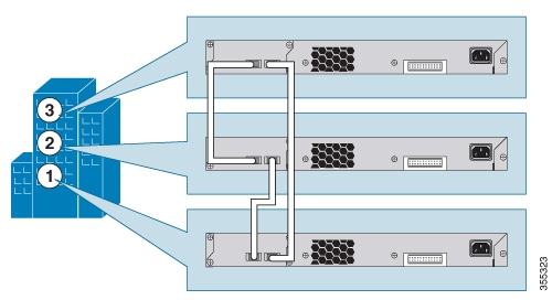
Connecting FlexStack-Plus modules (Optional)
Always use a Cisco-approved FlexStack cable to connect the switches.
Note | This is only supported on the stack-capable switches. |
Caution | Use only approved cables, and connect only to other Catalyst 6800IA switches. Equipment might be damaged if connected to other nonapproved Cisco cables or equipment. |
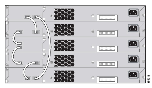
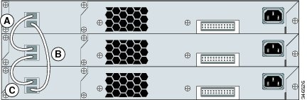
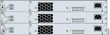
| Step 1 | Remove the dust covers from the FlexStack cables, and store them for future use. | ||
| Step 2 | Insert one end of the FlexStack cable into the stack port of the first switch. Insert the other end of the cable into the stack port on the other switch. Make sure that you insert the cables in completely until you feel them snap into place. 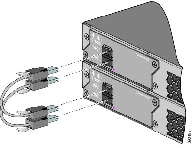
| ||
| Step 3 | Replace the dust covers when you remove the FlexStack cables from the connectors.
|
Removing a FlexStack Cable
| Step 1 | To remove a FlexStack cable, grasp the tab on the cable connector and gently pull straight out. | ||
| Step 2 | When you remove the FlexStack cables from the connectors, replace the dust covers to protect them from dust.
|
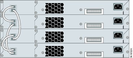
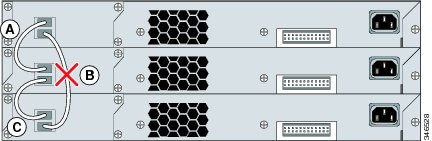
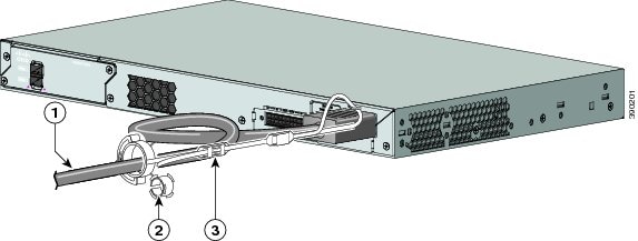
Installing the Power Cord Retainer (Optional)
Note | This section applies only to the Catalyst 6800IA-48FPD and 6800IA-48TD switches. |
The power cord retainer is optional (part number [PWR-CLP=]). You can order it when you order your switch, or you can order it later from your Cisco representative.
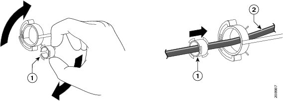
| Step 1 | Choose the sleeve size of the power cord retainer based on the thickness of the cord. The smaller sleeve can be snapped off and used for thin cords. | ||||||||
| Step 2 | Slide the retainer around the
AC power cord, and pass it around the loop on the switch.
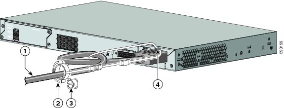 | ||||||||
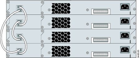
| Step 3 | Slide the retainer through
the first latch.
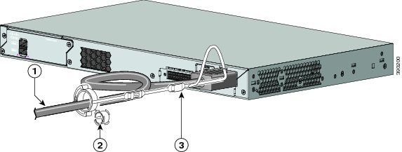 | ||||||||
| Step 4 | Slide the retainer through
the other latches to lock it.
 | ||||||||
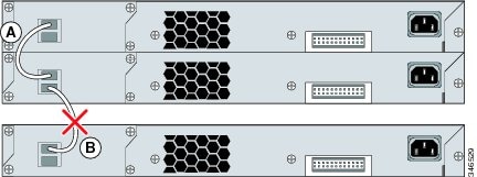
| Step 5 | (Optional) Use the small
sleeve for thin power cords. Use the small sleeve to provide greater stability
for thin cords. Detach the sleeve, and slide it over the power cord.
 | ||||||||
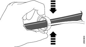
| Step 6 | Secure the AC power cord by
pressing on the retainer.
 |
Installing SFP Modules
Installing an SFP or SFP+ Module
When installing SFP or SFP+ modules, observe these guidelines:
Do not remove the dust plugs from the modules or the rubber caps from the fiber-optic cable until you are ready to connect the cable. The plugs and caps protect the module ports and cables from contamination and ambient light.
To prevent ESD damage, follow your normal board and component handling procedures when connecting cables to the switch and other devices.
CautionRemoving and installing an SFP or SFP+ module can shorten its useful life. Do not remove and insert any module more often than is absolutely necessary.
| Step 1 | Attach an ESD-preventive wrist strap to your wrist and to a bare metal surface. |
| Step 2 | Find the send (TX) and receive (RX) markings on the module top. On some SFP or SFP+ modules, the send and receive (TX and RX) markings might be replaced by arrows that show the direction of the connection. |
| Step 3 | If the module has a bale-clasp latch, move it to the open, unlocked position. |
| Step 4 | Align the module in front of the slot opening, and push until you feel the connector snap into place. |
| Step 5 | If the module has a bale-clasp latch, close it. |
| Step 6 | For fiber-optic SFP or SFP+ modules, remove the dust plugs and save. |
| Step 7 | Connect the SFP cables. 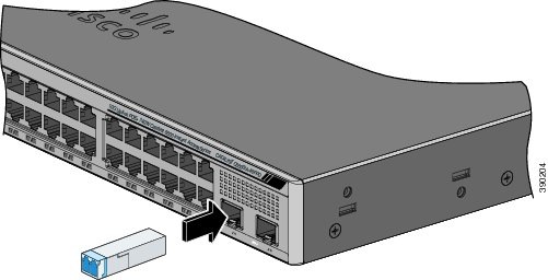 |
Removing an SFP Module
Connecting to SFP and SFP+ Modules
Connecting to Fiber-Optic SFP and SFP+ Modules
Warning | Class 1 laser product. Statement 1008 |
Caution | Do not remove the rubber plugs from the SFP or SFP+ module port or the rubber caps from the fiber-optic cable until you are ready to connect the cable. The plugs and caps protect the SFP module ports and cables from contamination and ambient light. Before connecting to the SFP module, be sure that you understand the port and cabling stipulations. |
| Step 1 | Remove the rubber plugs from the module port and fiber-optic cable, and store them for future use. |
| Step 2 | Insert one end of the fiber-optic cable into the SFP or SFP+ module port. |
| Step 3 | Insert the other cable end into a fiber-optic receptacle on a target device. 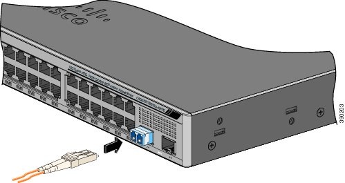 |
| Step 4 | Observe the port status LED.
The LED turns green when the switch and the target device have an established link. The LED turns amber while the STP discovers the network topology and searches for loops. This process takes about 30 seconds, and then the port LED turns green. If the LED is off, the target device might not be turned on, there might be a cable problem, or there might be problem with the adapter installed in the target device. |
Connecting to 1000BASE-T SFP
When connecting to a 1000BASE-T device, be sure to use a four twisted-pair, Category 5 or higher cable.
Note | The automatic medium-dependent interface crossover (auto-MDIX) feature is enabled by default. For configuration information for this feature, see the switch software configuration guide or the switch command reference on Cisco.com. |
Caution | To prevent ESD damage, follow your normal board and component handling procedures. |
| Step 1 | Connect one end of the cable to the SFP module port. Insert a four twisted-pair, straight-through cable when you connect to servers, workstations, and routers. Insert a four twisted-pair, crossover cable when you connect to switches or repeaters. | ||
| Step 2 | Connect the other end of the cable to an RJ-45 connector on the other device. 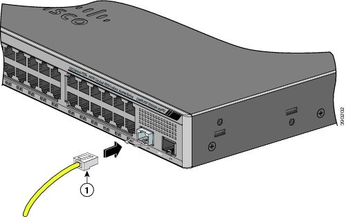
| ||
| Step 3 | Observe the port status LED.
| ||
| Step 4 | If necessary, reconfigure and restart the switch or other device. |
10/100/1000 PoE and PoE+Port Connections
The ports provide PoE support for devices compliant with IEEE 802.3af and 802.3at (PoE+), and also provide Cisco prestandard PoE support for Cisco IP Phones and Cisco Aironet Access Points.
On a per-port basis, you can control whether or not a port automatically provides power when an IP phone or an access point is connected.
To access an advanced PoE planning tool, use the Cisco Power Calculator available on Cisco.com at this URL: http://tools.cisco.com/cpc/launch.jsp
You can use this application to calculate the power supply requirements for a specific PoE configuration. The results show output current, output power, and system heat dissipation.
Warning | Voltages that present a shock hazard may exist on Power over Ethernet (PoE) circuits if interconnections are made using uninsulated exposed metal contacts, conductors, or terminals. Avoid using such interconnection methods, unless the exposed metal parts are located within a restricted access location and users and service people who are authorized within the restricted access location are made aware of the hazard. A restricted access area can be accessed only through the use of a special tool, lock and key or other means of security. Statement 1072 |
Caution | Category 5e and Category 6 cables can store high levels of static electricity. Always ground the cables to a suitable and safe earth ground before connecting them to the switch or other devices. |
Caution | Noncompliant cabling or powered devices can cause a PoE port fault. Use only standard-compliant cabling to connect Cisco prestandard IP Phones and wireless access points, IEEE 802.3af, or 802.3at (PoE+) compliant devices. You must remove any cable or device that causes a PoE fault. |
| Step 1 | Connect one end of the cable to the switch PoE port. | ||
| Step 2 | Connect the other end of the
cable to an RJ-45 connector on the other device. The port LED turns on when
both devices have established link.
The port LED is amber while STP discovers the topology and searches for loops. This process takes about 30 seconds, and then the port LED turns green. If the LED is off, the other device might not be turned on, there might be a cable problem, or there might be a problem with the adapter in the other device. | ||
| Step 3 | Reconfigure and reboot the connected device, if needed. | ||
| Step 4 | Repeat Steps 1 through 3 to
connect each device.
|
10/100/1000 Port Connections
The switch 10/100/1000 port configuration changes to operate at the speed of the attached device. If the attached ports do not support autonegotiation, you can manually set the speed and duplex parameters. Connecting devices that do not autonegotiate or that have the speed and duplex parameters manually set can reduce performance or result in no linkage.
To maximize performance, choose one of these methods for configuring the Ethernet ports:
Auto-MDIX Connections
The autonegotiation and the auto-MDIX features are enabled by default on the switch.
With autonegotiation, the switch port configurations change to operate at the speed of the attached device. If the attached device does not support autonegotiation, you can manually set the switch interface speed and duplex parameters.
With auto-MDIX, the switch detects the required cable type for copper Ethernet connections and configures the interface accordingly.
Where to Go Next
Refer to the "Instant Access" chapter in the Release 15.1SY Supervisor Engine 2T Software Configuration Guide.
 Feedback