-
null
Product
Overview
The Catalyst 6800IA switches are Ethernet switches to which you can connect devices such as Cisco IP Phones, Cisco Wireless Access Points, workstations, and other network devices such as servers, routers, and other switches.
The switches support stacking through the Cisco FlexStack technology. Unless otherwise noted, the term switch refers to a standalone switch and to a switch stack.
This chapter contains these topics:
Switch Models
|
Switch Model |
Description |
|---|---|
|
Catalyst 6800IA-48FPDR |
48 10/100/1000 Power over Ethernet Plus (PoE+) ports (PoE budget of 740 W) and 2 small form-factor pluggable (SFP)+1 module slots, 1025-W power supply. |
|
Catalyst 6800IA-48FPD |
48 10/100/1000 PoE+ ports (PoE budget of 740 W) and 2 SFP+ module slots. |
|
Catalyst 6800IA-48TD |
48 10/100/1000 ports and 2 SFP+ module slots. |
Front Panel
This section describes the front panel components:
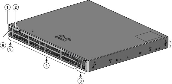
1 |
Mode button and switch LEDs |
4 |
10/100/1000 PoE+ ports |
2 |
USB mini-Type B (console) port |
5 |
RJ-45 console port |
3 |
SFP+ module slots |
6 |
Ethernet management port |
PoE and PoE+ Ports
The ports provide PoE+ support for devices compliant with IEEE 802.3af, IEEE 802.3at, and ePoE and also provide Cisco prestandard PoE support for Cisco IP Phones and Cisco Aironet Access Points.
The maximum switch power output is 740 W. Intelligent power management allows flexible power allocation across all ports.
For switches with a 740 W power budget, you can budget the PoE and PoE+:
On a per-port basis, you control whether or not a port automatically provides power when an IP phone or an access point is connected.
The PoE ports use RJ-45 connectors with Ethernet pinouts. The maximum cable length is 328 feet (100 meters). The 10BASE-T, 100BASE-TX, 1000BASE-T traffic requires Category 5, Category 5e, or Category 6 unshielded twisted pair (UTP) cable. The 10BASE-T traffic can use Category 3 or Category 4 UTP cable.
Cisco intelligent power management capabilities include enhanced power negotiation, power reservation, and per-port power policing. For information about configuring and monitoring PoE ports, see the switch software configuration guide on Cisco.com.
 Note | The output of the PoE circuit has been evaluated as a Limited Power Source (LPS) per IEC 60950-1. |
10/100/1000 Ports
The 10/100/1000 ports use RJ-45 connectors with Ethernet pinouts. The maximum cable length is 328 feet (100 meters). The 10BASE-T, 100BASE-TX, 1000BASE-T traffic requires Category 5 or Category 5e twisted pair (UTP) cable. The 10BASE-T traffic can use Category 3 or Category 4 UTP cable.
Management Ports
The management ports connect the switch to a PC running Microsoft Windows or to a terminal server.
The 10/100 Ethernet management port connection uses a standard RJ-45 crossover or straight-through cable. The RJ-45 console port connection uses the supplied RJ-45-to-DB-9 female cable. The USB console port connection uses a USB Type A to 5-pin mini-Type B cable. The USB console interface speeds are the same as the RJ-45 console interface speeds.
If you use the USB mini-Type B console port, the Cisco Windows USB device driver must be installed on any PC connected to the console port (for operation with Microsoft Windows). Mac OS X or Linux do not require special drivers.
The 4-pin mini-Type B connector resembles the 5-pin mini-Type B connectors. They are not compatible. Use only the 5-pin mini-Type B.

With the Cisco Windows USB device driver, you can connect and disconnect the USB cable from the console port without affecting Windows HyperTerminal operations.
The console output always goes to both the RJ-45 and the USB console connectors, but the console input is active on only one of the console connectors at any one time. The USB console takes precedence over the RJ-45 console. When a cable is connected into the USB console port, the RJ-45 console port becomes inactive. Conversely, when the USB cable is disconnected from the USB console port, the RJ-45 port becomes active.
You can use the command-line interface (CLI) to configure an inactivity timeout which reactivates the RJ-45 console if the USB console has been activated and no input activity has occurred on the USB console for a specified time.
After the USB console deactivates due to inactivity, you cannot use the CLI to reactivate it. Disconnect and reconnect the USB cable to reactivate the USB console. For information on using the CLI to configure the USB console interface, see the software guide.
SFP+ Module Slots
The switch has two 10-Gigabit SFP+ module slots that support both SFP and SFP+ modules.
For Cisco SFP and SFP+ modules documentation, including compatibility matrixes, refer to this URL: http://www.cisco.com/en/US/products/hw/modules/ps5455/products_device_support_tables_list.html
LEDs
You can use the switch LEDs to monitor switch activity and its performance.
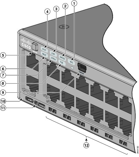
|
STACK LED |
|||
|
PoE LED4 |
|||
|
USB mini-Type B console port LED |
|||
|
11 |
CONSOLE LED |
||
|
6 |
Master LED |
12 |
Port LEDs |
- System LED
- RPS LED
- IRPS LED
- Master LED
- Port LEDs and Modes
- STACK LED
- Console LEDs
- Ethernet Management Port LED
System LED
Blinking amber |
System is sleep mode. |
RPS LED
The RPS LED is only available on switch models that have an RPS port (Catalyst 6800IA-48FPD and 6800IA-48TD switches).
IRPS LED
The IRPS LED is only available on the Catalyst 6800IA-48FPDR switch.
|
The second power supply is present, but the input is not connected. |
|
|
The second power supply is present, but the signal is faulty. |
Master LED
An error occurred when the stack was electing the stack master switch, or another type of stack error occurred. |
Port LEDs and Modes
The port and module slots each has a port LED. As a group or individually, the LEDs show information about the switch and about the ports.
To select or change a mode, press the Mode button until the desired mode is highlighted. When you change port modes, the meanings of the port LED colors also change.
Port Mode |
Port LED Color |
Meaning |
|---|---|---|
PoE |
Off |
PoE is off. If the powered device is receiving power from an AC power source, the port LED is off even if the powered device is connected to the switch port. |
Green |
PoE is on. The port LED is green only when the switch port is providing power. |
|
Alternating green and amber |
PoE is denied because providing power to the powered device will exceed the switch power capacity. |
|
Blinking amber |
PoE is off due to a fault. Noncompliant cabling or powered devices can cause a PoE port fault. Use only standard-compliant cabling to connect Cisco prestandard IP Phones and wireless access points or IEEE 802.3af-compliant devices. You must remove any cable or device that causes a PoE fault. |
|
Amber |
PoE for the port is disabled. (PoE is enabled by default.) |
|
STAT (port status) |
Off |
No link or port was administratively shut down. |
Green |
Link present. |
|
Blinking green |
Activity. Interface is sending or receiving data. |
|
Alternating green-amber |
Link fault. Error frames can affect connectivity, and errors such as excessive collisions, cyclic redundancy check (CRC) errors, and alignment and jabber errors are monitored for a link-fault indication. |
|
Amber |
Port is blocked by Spanning Tree Protocol (STP) and is not forwarding data. After a port is reconfigured, the port LED can remain amber for up to 30 seconds as STP searches the switch for possible loops. |
|
Blinking amber |
Port is blocked by STP and is sending and receiving packets. |
|
SPEED |
10/100/1000 ports |
|
Off |
Port is operating at 10 Mb/s. |
|
Green |
Port is operating at 100 Mb/s. |
|
Blinking green |
Port is operating at 1000 Mb/s. |
|
SFP+ module ports |
||
Off |
Port is not operating. |
|
Blinking green |
Port is operating at 10 Gb/s. |
|
Green |
Port is operating at 1 Gb/s. |
|
STACK (stack member) |
Off |
No stack member has that member number. |
Blinking green |
Stack member number. |
|
Green |
Member numbers of other stack member switches. |
|
If your switches are stacked and you press the Mode button on any switch, all the switches display the same selected mode. For example, if you press the Mode button on the stack master to display SPEED, all the other stack members display SPEED.
Note | If you press the Mode button for more than 3 seconds on any switch or the stack master, the switch enters the Express Setup mode which will reset and reboot the FEX or the FEX stack. Express Setup is enabled by default and you must disable it to prevent the switch from accidentally entering the Express Setup mode. To disable Express Setup, Contact Cisco TAC. |
Even if PoE mode is not selected, this LED still shows PoE problems if they are detected.
STACK LED
The STACK LED shows the sequence of member switches in a stack. Up to five switches can be members of a stack. The first five port LEDs show the switch member number. For example, if you press the Mode button and select Stack, the port LED 1 blinks green. The LEDs for port 2 and 3 are solid green, as these represent the member numbers of other stack members. The other port LEDs are off because there are no more members in the stack.
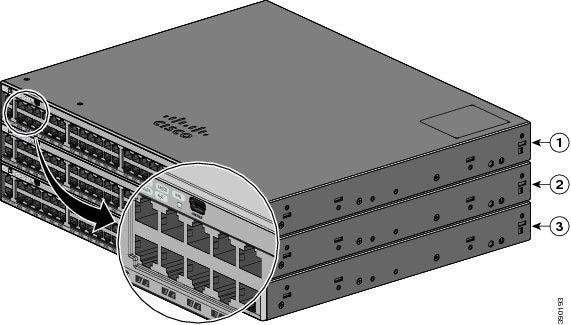
When you select the STACK LED, the respective STACK LEDs are green when the stack ports (on the switch rear panel) are up, and the respective Stack LEDs are amber when the ports are down. SFP+ module port LEDs 1 and 2 on the switch show the status for stack ports 1 and 2, respectively.
If the port LEDs are green on all the switches in the stack, the stack is operating at full bandwidth. If any port LED is not green, the stack is not operating at full bandwidth.
Console LEDs
The console LEDs show which console port is in use. If you connect a cable to a console port, the switch automatically uses that port for console communication. If you connect two console cables, the USB console port has priority.
The port is not active, and the RJ-45 console port is active. |
Ethernet Management Port LED
Rear Panel
The rear panel of the Catalyst 6800IA-48FPD and 6800IA-48TD switches have FlexStack-Plus ports, a fan exhaust, an RPS connector, and an AC power connector.
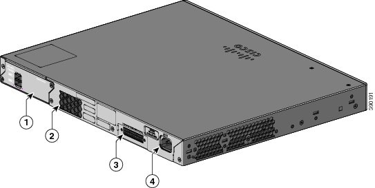
|
1 |
FlexStack-Plus ports |
3 |
RPS Connector |
|
2 |
Fan Exhaust |
4 |
AC power connector |
The rear panel of the Catalyst 6800IA-48FPDR switches have FlexStack-Plus ports and power supply module slots.
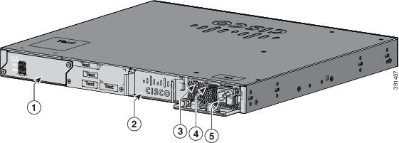
|
1 |
FlexStack-Plus ports |
4 |
PS OK LED |
|
2 |
Power supply slot (with blank module) |
5 |
AC power connector on the power supply module |
|
3 |
AC OK LED |
- FlexStack-Plus Ports and LEDs
- RPS Connector
- AC Power Connector
- Power Supply Modules (Applies to the Catalyst 6800IA-48FPDR Switches)
FlexStack-Plus Ports and LEDs
The Catalyst 6800IA switches support stacking with the FlexStack-Plus ports on the switch rear panel and a 0.5-meter FlexStack cable.
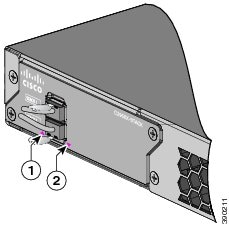
1 |
LED for Stack port 1 |
2 |
LED for Stack port 2 |
Switch |
Number of Switches in the Stack |
Bandwidth |
|---|---|---|
Stack with Catalyst 6800IA switches |
3 | 80 G |
RPS Connector
The Cisco RPS 2300 (model PWR-RPS2300) supports the Catalyst 6800IA-48FPD and 6800IA-48TD switches .
 Warning | Attach only the following Cisco RPS model to the RPS receptacle: RPS2300. Statement 370 |
Connect the switch and the redundant power system to different AC power sources.
Cisco RPS 2300
The Cisco RPS 2300 is a redundant power system that can support six external network devices and provide power to one or two failed devices at a time. It senses when the internal power supply of a connected device fails and provides power to the failed device, preventing loss of network traffic. For more information, see the Cisco Redundant Power System 2300 Hardware Installation Guide on Cisco.com at this URL: http://www.cisco.com/en/US/products/ps7148/prod_installation_guides_list.html
The Cisco RPS 2300 has two output levels: –52 V and 12 V with a total maximum output power of 2300 W.
All supported and connected switches can simultaneously communicate with the RPS 2300. You can configure these RPS 2300 features through the switch software:
AC Power Connector
Note | This applies to the Catalyst 6800IA-48FPD and Catalyst 6800IA-48TD switches. |
The switch is powered through the internal power supply. The internal power supply is an autoranging unit that supports input voltages between 100 and 240 VAC. Use the supplied AC power cord to plug it into an AC power outlet.
Power Supply Modules (Applies to the Catalyst 6800IA-48FPDR Switches)
The switch operates with either one or two active power supply modules. You can use two AC modules, or one module and a blank cover.
|
PWR-C2-1025WAC= |
1025-W AC power supply module. |
The 1025-W power supply module is an autoranging unit that supports input voltages between 115 and 240 VAC. All power supply modules have internal fans. All switches ship with a blank cover in the second power supply slot.
| Primary Power Supply | Secondary Power Supply | Available Power for PoE+ | Switch Power Redundancy | Available PoE Power when One PS Fails |
|---|---|---|---|---|
|
PWR-C2-1025WAC= |
— |
740 W |
No |
— |
|
PWR-C2-1025WAC= |
PWR-C2-1025WAC= |
740 W |
Yes |
740 W |
 Feedback