Catalyst 6800IA Switch Hardware Installation Guide
Bias-Free Language
The documentation set for this product strives to use bias-free language. For the purposes of this documentation set, bias-free is defined as language that does not imply discrimination based on age, disability, gender, racial identity, ethnic identity, sexual orientation, socioeconomic status, and intersectionality. Exceptions may be present in the documentation due to language that is hardcoded in the user interfaces of the product software, language used based on RFP documentation, or language that is used by a referenced third-party product. Learn more about how Cisco is using Inclusive Language.
- Updated:
- July 16, 2014
Chapter: Power Supply Installation
Power Supply
Installation
This chapter applies only to the Catalyst 6800IA-48FPDR switch. It contains these topics:
- Power Supply Module Overview
- Installation Guidelines
- Installing or Replacing an AC Power Supply
- Finding the Serial Number
Power Supply Module Overview
The switch operates with either one or two active power supply modules. You can use two AC modules, or one module and a blank cover.
|
PWR-C2-1025WAC= |
1025-W AC power supply module |
The 1025-W power supply module is an autoranging unit that supports input voltages between 115 and 240 VAC. All power supply modules have internal fans. All switches ship with a blank cover in the second power supply slot.
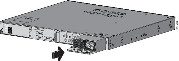
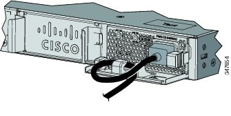
Each AC power supply module has a power cord for connection to an AC power outlet.

|
1 |
AC OK LED |
4 |
AC power cord connector |
|
2 |
PS OK LED |
5 |
Release latch |
|
3 |
AC power cord retainer |
6 |
Power supply |
If no power supply is installed in a power supply slot, install a power supply slot cover.
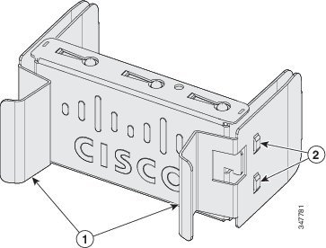
|
1 |
Release handles |
2 |
Retainer clips |
The power supply modules have two status LEDs.
|
AC OK |
Description |
PS OK |
Description |
|---|---|---|---|
|
Off (AC LED is off) |
No AC input power. |
Off |
Output is disabled, or input is outside operating range. |
|
Green |
AC input power is present. |
Green |
Power output to switch. |
|
Red |
Output has failed. |
Installation Guidelines
Observe these guidelines when removing or installing a power supply module:
-
Do not force the power supply module into the slot. This can damage the pins on the switch if they are not aligned with the module.
-
A power supply that is only partially connected to the switch can disrupt the system operation.
-
Remove power from the power-supply module before removing or installing the module.
 Caution | Do not operate the switch with one power-supply module slot empty. For proper chassis cooling, both module slots must be populated, with either a power supply or a blank module. |
 Warning | Blank faceplates and cover panels serve three important functions: they prevent exposure to hazardous voltages and currents inside the chassis; they contain electromagnetic interference (EMI) that might disrupt other equipment; and they direct the flow of cooling air through the chassis. Do not operate the system unless all cards, faceplates, front covers, and rear covers are in place. Statement 1024 |
Warning | Do not reach into a vacant slot or chassis while you install or remove a module. Exposed circuitry could constitute an energy hazard. Statement 206 |
Warning | Only trained and qualified personnel should be allowed to install, replace, or service this equipment. Statement 1030 |
Warning | If a Cisco external power system is not connected to the switch, install the provided connector cover on the back of the switch. Statement 386 |
Installing or Replacing an AC Power Supply
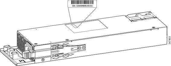
Finding the Serial Number
If you contact Cisco Technical Assistance, you need to know the switch serial number. You can also use the show version privileged EXEC command to see the switch serial number.
 Feedback