- About Programmability
- Configuring Programmability
- Prerequisites for Configuring Programmability
- Restrictions and Limitations for Configuring Programmability
- Zero-Touch Provisioning Requirements
- PXE Requirements and Process Flow
- Installing the DMI Container
- Configuring OneP
- Providing Privilege Access to Use NetCONF and RestCONF
- Enabling Cisco IOS HTTP Services for RestCONF
- Monitoring Programmability
- Troubleshooting Programmability
Configuring Programmability
Programmability is supported only on Catalyst 4500-E Series Switches with Supervisor Engine 8-E, 8L-E, and the Catalyst 4500-X Series Switches. The feature is supported on all available license levels for these switches. This chapter describes how to configure the feature and includes the following major sections:
About Programmability
Overview
Programmability is about how you can use data modeling languages and protocols to interact with the operating system (Cisco IOS XE) of a switch.
The traditional way of interacting or communicating with Cisco networking devices, has been manual configuration, through the command line interface (CLI). As deployments become more complex, programmability of devices has enabled a shift from manual network provisioning and configuration to automation.
Managing device configuration programmatically enables you to:
- Configure and control at scale—You can automate network configuration while also overcoming difficulties posed by multiple platforms, multiple operating systems, and multiple vendor devices in your network.
- Check to make sure that dependencies are satisfied before committing a change; and also easily roll-back when changes are not consistently compatible across the network.
To address configuration and monitoring issues, the Internet Engineering Task Force (IETF) has defined new standards in network management:
- Yet Another Next Generation (YANG) data modeling—RFC 6020.
- Network Configuration Protocol (NETCONF)—RFC 6241
- Representational State Transfer Configuration Protocol (RESTCONF)–uses the same data models as defined for NETCONF using YANG ( https://tools.ietf.org/html/draft-ietf-netconf-restconf-04).
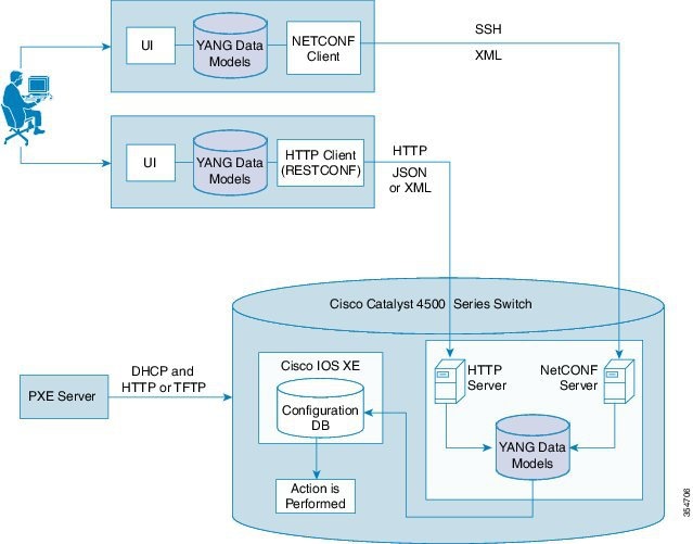
On Catalyst 4500 Series Switches, the Programmability feature introduces the use of NetCONF and RestCONF interfaces. They reside in a container on the switch and provide interfaces that enable remote management. The YANG data models available with these interfaces determine the scope of functions or actions that can be performed. See Figure 1-1.
Programmability Components
This section describes the network management tools used for programmability, in detail:
- NetCONF—an XML-based protocol that you can use to request information from and make configuration changes to the switch. NetCONF Application Programming Interfaces (APIs) use Secure Shell Version 2 (SSHv2).
- RestCONF—a JSON-based protocol that serves as an additional programming interface to implement the equivalent of NetCONF. RestCONF APIs use HTTP methods.
- YANG models—A data modeling language that defines the payload on NETCONF protocol messages. Data models determine the scope and the kind of functions that can be performed by NetCONF and RestCONF APIs. The following data model is available:
The Cisco ned.yang model—This is a configuration data model; it enables to you perform write (SET) operations. The IETF, or common models are not supported.
These components, enable you to set up what is required for Programmability:
- Virtual Services Container—Also referred to as a virtual machine (VM), virtual service, or container, is a virtual environment on a device.
You can install an application within a virtual services container. The application then runs in the virtual services container of the operating system of a device. The application is delivered as an open virtual application (OVA), which is a tar file with a.ova extension. The OVA package is installed and enabled on a device through the device CLI.
- Data Model Interface (DMI)—A container that provides the NetCONF and RestCONF programmable interfaces. You must install and activate this container on the switch. After you activate it, the YANG models and APIs are available for use.
- Pre-Boot Execution Environment (PXE)—A network boot loader that enables a device to retrieve configuration files, scripts and.ova files from the remote DHCP server during initial deployment, without end-user intervention (zero-touch provisioning). You can boot the device and use TFTP to download user configuration files, scripts, and OVA files.
Figure 1-1 shows how the different components of Programmability come together.
Figure 1-1 Programmability Components
Default Configuration
Configuring Programmability
You can configure this feature by means of zero touch provisioning (also known as Day 0 configuration) or the standard configuration method (by configuring all required tasks individually).
The following is relevant to both methods of configuration:
- Prerequisites for Configuring Programmability
- Restrictions and Limitations for Configuring Programmability
- PXE Requirements and Process Flow
For zero touch provisioning, you must ensure that you have met:
For the standard configuration method, you must complete the following:
- Installing the DMI Container
- Configuring OneP
- Providing Privilege Access to Use NetCONF and RestCONF
- Enabling Cisco IOS HTTP Services for RestCONF
Prerequisites for Configuring Programmability
Your access to the switch is configured with privilege level 15. This is required to start working with NetCONF and RestCONF interfaces. See Providing Privilege Access to Use NetCONF and RestCONF.
- To be able to download the device start-up configuration, script, and the ova files to the switch, you must use the Engineering Special image as the boot image:
With the Catalyst 4500-X Series Switches, use the following boot image and.ova file name:
–![]() cat4500e-universalk9.SPA.03.09.00.PRT.1.152-5.0.1.PRT.bin
cat4500e-universalk9.SPA.03.09.00.PRT.1.152-5.0.1.PRT.bin
With the Catalyst 4500-E Series Switches, use the following boot image and.ova file name:
–![]() cat4500es8-universalk9.SPA.03.09.00.PRT.1.152-5.0.1.PRT.bin
cat4500es8-universalk9.SPA.03.09.00.PRT.1.152-5.0.1.PRT.bin

Note![]() If you are not using the PXE to boot, you do not have to upgrade the ROMMON version.
If you are not using the PXE to boot, you do not have to upgrade the ROMMON version.
–![]() The software configuration register is set to autoboot. PXE is supported only if you have enabled autoboot.
The software configuration register is set to autoboot. PXE is supported only if you have enabled autoboot.
Note For zero touch provisioning, the configuration register is set to autoboot by default.
–![]() The required ROMMON version is installed:
The required ROMMON version is installed:
On Catalyst 4500-X Series Switches, ROMMON version 15.0(1r)SG13 applies.
On Catalyst 4500-E Series Switches, ROMMON version 15.1(1r)SG7 applies.
With the above ROMMON versions, the system prioritizes the PXE boot; if PXE is not available, it follows the usual order.
Restrictions and Limitations for Configuring Programmability
- The IETF, or common data models are not supported. Only the Cisco ned.yang model is supported for configuration.
- ISSU is not supported.
- IPv6 addresses are not supported on NETCONF and RESTCONF interfaces.
- The DMI is not supported in the VSS mode.
- Although there is no software restriction, we recommend that you have no more than 4 simultaneous NETCONF sessions.
- Do not use IP address 192.168.x.1 for communication, NETCONF is not supported if you do.
- RESTCONF is not supported with HTTPS.
- Zero touch provisioning (PXE boot) is not supported with Cisco Catalyst 4500E Supervisor Engines 8-E and 8L-E. On these devices you must install and activate the DMI.ova manually.
- NETCONF is not supported on an IP address assigned to a Switched Virtual Interface (SVI) where the port channels are members of that VLAN.
Zero-Touch Provisioning Requirements
For the zero-touch provisioning or Day 0 configuration, ensure that you have completed the following:
- Configured the DHCP server and TFTP server. For more information, see PXE Requirements —Configuring the DHCP Server
- Entered the following global configuration commands in the start-up configuration file. This file is downloaded during the PXE process
–![]() The virtual-service DMI command (The virtual service name must be DMI if one opts for day0 configuration).
The virtual-service DMI command (The virtual service name must be DMI if one opts for day0 configuration).
–![]() The ip shared host-interface interface-id command
The ip shared host-interface interface-id command
–![]() The username name privilege level password password command
The username name privilege level password password command
–![]() The ip http authentication local command
The ip http authentication local command
The following is a sample of the device start-up configuration file with the required commands:
PXE Requirements and Process Flow
PXE Requirements —Configuring the DHCP Server
To send switch startup configuration files, scripts and.ova files in addition to the bootable image, you must configure the DHCP server.
Depending on your existing DHCP server setup (whether on Microsoft Windows or Linux), ensure that you have made the corresponding, requisite settings.
See Sample Configuration and Reference Information.
DHCP Configuration Guidelines:
–![]() In the DHCP configuration file:
In the DHCP configuration file:
The following information is mandatory: gateway, subnet mask and TFTP server IP address, and the client IP address in the DHCP configuration file. For example:
The following information is optional. Depending on your requirement, you can specify one or more options: the boot image name, the start-up configuration file name and path, the script file name and path, and the ova file name and path. For example:
#ENTER A FILE NAME. MAKE SURE THAT CONFIG, SCRIPT, AND CONTAINER FILE EXTENTIONS ARE <config-file>.config,<script-file>.script,<container-file>.ova RESPECTIVELY.
option EXAMPLE.startup-config "configs/sup8le.config";
option EXAMPLE.user-script "scripts/hello.script";
option EXAMPLE.user-ova "container/cat4500e_20160801-172004_47.ova";
option dhcp-parameter-request-list 43,3;
If you are using the above optional parameters, you must use the Engineering Special image as the boot image to be able to download the device start-up configuration, script, and the ova files to the switch.
–![]() When the DHCP server responds successfully, the output displays Received DHCP_ACK.
When the DHCP server responds successfully, the output displays Received DHCP_ACK.
–![]() If you receive a TFTP timeout error, increase the DHCP timeout by using a ROMMON variable DhcpTimeout. The default DHCP timeout is 5 seconds. You can increase the DHCP timeout by a maximum of 30 seconds. For example, if DhcpTimeout=20, the DHCP timeout increases by 20 seconds.
If you receive a TFTP timeout error, increase the DHCP timeout by using a ROMMON variable DhcpTimeout. The default DHCP timeout is 5 seconds. You can increase the DHCP timeout by a maximum of 30 seconds. For example, if DhcpTimeout=20, the DHCP timeout increases by 20 seconds.
–![]() You can interrupt the autoboot process at any point, by pressing Control +C (switches to the ROMMON mode).
You can interrupt the autoboot process at any point, by pressing Control +C (switches to the ROMMON mode).
–![]() The device configuration file, scripts and ova files should be saved in the TFTP root folder. This applies to DHCP server configuration using the Microsoft Windows and Linux.
The device configuration file, scripts and ova files should be saved in the TFTP root folder. This applies to DHCP server configuration using the Microsoft Windows and Linux.
–![]() DHCP information such as IP address, gateway etc., are not permanently stored on switch. They are used only to download files and are deleted when the activity is complete.
DHCP information such as IP address, gateway etc., are not permanently stored on switch. They are used only to download files and are deleted when the activity is complete.
–![]() The DHCP boot ignores network information that you configure on the ROMMON, such as IP, gateway, subnet mask etc.
The DHCP boot ignores network information that you configure on the ROMMON, such as IP, gateway, subnet mask etc.
PXE Process Flow
If you have completed the required DHCP server configuration, the PXE follows the sequence of events given below.
1. The switch sends a DHCP discovery packet.
2. The DHCP server responds with an offer containing the TFTP server IP address, the offered IP address for the client, the gateway IP address, the boot file name, and the path and names of the OVA, script, and switch configuration files.
3. The switch sends the DHCP request for the IP address.
4. After the switch receives the DHCP acknowledgment packet from the server, the configuration file and OVA file information is cached in the flash 0 user partition.
5. The switch boots or powers up with the image specified in the filename variable in the DHCP configuration file.
6. During bootup, the switch checks for device configuration files, script files, and ova files. If there are such files, the switch sends the file information using DHCP Option 43 and downloads the required files.
The following is sample output of the autoboot process:
Note If you are not using PXE to boot, but are still using the new ROMMON versions, the following is displayed at the beginning of the boot process. You can ignore this. The boot process resumes normally.
Installing the DMI Container
This task is mandatory if you have opted for the standard configuration method.
Before you begin, ensure that you have completed the following:
- Downloaded an OVA package that is compatible with the device operating system. The OVA package is available for download in the same location as your system image (.bin) file.
- Ensured that the minimum required disk space - 512 MB, and memory - 256 MB RAM is available on the device for installation and deployment of the DMI container.
To install and activate the DMI by using the virtual services container CLI, perform the following task:
Configuring OneP
This task is mandatory if you have opted for the standard configuration method.
To enable the requisite, internal OneP infrastructure, perform the following task:
Providing Privilege Access to Use NetCONF and RestCONF
This task is mandatory for both zero touch provisioning, and the standard configuration method.
To start working with NetCONF and RestCONF APIs you must be a user with privilege level 15. To provide this, perform the following task:
With the above task completed, the NetCONF interface is available. See Examples for NETCONF RPCs
To use the RestCONF interface, you must perform one more task. See Enabling Cisco IOS HTTP Services for RestCONF.
Enabling Cisco IOS HTTP Services for RestCONF
This task is mandatory if you want to use the RestCONF interface and have opted for the standard configuration method.
With the above task completed, the RESTCONF interface is available. See Examples for RESTCONF RPCs:
Monitoring Programmability
Use these commands in the privileged EXEC mode, to display the Programmability settings you have configured:
Troubleshooting Programmability
This section shows sample output for the some of the errors you may encounter while configuring the feature. In some cases a solution is described, and in others, sample configuration output serves as a guideline for correct configuration.
If you receive a TFTP timeout error, increase the DHCP timeout by using a ROMMON variable DhcpTimeout. The default DHCP timeout is 5 seconds. You can increase the DHCP timeout by a maximum of 30 seconds. For example, if DhcpTimeout=20, the DHCP timeout increases by 20 seconds
If you receive such an error, check the path you have entered for the filename field in the DHCP configuration file and make sure that the file exists in your TFTP server. See sample output below, it shows a successful TFTP session:
If you encounter errors when you replace existing startup configuration with new configuration, the system does not replace existing startup configuration. You must to resolve the errors in the device (switch) configuration file before resuming.
To start debugging the DMI container:
Step 1![]() Set the logging level to “debug” in cisco-ia.yang model.
Set the logging level to “debug” in cisco-ia.yang model.
Step 2![]() Enter the following commands in the privilege EXEC Mode:
Enter the following commands in the privilege EXEC Mode:
Note![]() These are hidden commands and do not support tab or word help (the question mark (?) at the system prompt).
These are hidden commands and do not support tab or word help (the question mark (?) at the system prompt).
Step 3![]() To display NETCONF statistical information, such as, the number of sessions, netconf RPCs, packets and so on, use the ietf-netconf-monitoring.yang model.
To display NETCONF statistical information, such as, the number of sessions, netconf RPCs, packets and so on, use the ietf-netconf-monitoring.yang model.
 Feedback