Power Supply and Fan Module Installation
•![]() Installing an AC Power Supply
Installing an AC Power Supply
•![]() Finding the Power Supply Module Serial Number
Finding the Power Supply Module Serial Number
•![]() Finding the Fan Module Serial Number
Finding the Fan Module Serial Number
Power Supply Module Overview
The switch operates with either one or two active power supply modules or with power supplied by an expandable power supply, XPS 2200. A Catalyst 3750-X switch that is part of a StackPower stack operates with power supplied by other stack switches.
You can use two AC modules, two DC modules, one AC and one DC module, or one module and a blank cover.
All power supply modules have internal fans. All switches ship with a blank cover in the second power supply slot.
The XPS 2200 operates in two modes:
•![]() In StackPower mode, it supplies power to the switches in the power stack (only Catalyst 3750-X switches with IP Base image).
In StackPower mode, it supplies power to the switches in the power stack (only Catalyst 3750-X switches with IP Base image).
•![]() In expandable power supply mode, it supplies power to a switch when the switch power supply is removed or fails. When you install or replace a power supply module, the switch software polls the device. After polling, the power supply module provides power to the switch, and the XPS 2200 is available to power other devices.
In expandable power supply mode, it supplies power to a switch when the switch power supply is removed or fails. When you install or replace a power supply module, the switch software polls the device. After polling, the power supply module provides power to the switch, and the XPS 2200 is available to power other devices.
Table 3-1 describes the supported internal power supply modules.
|
|
|
|---|---|
C3KX-PWR-1100WAC |
1100-W AC power supply module |
C3KX-PWR-715WAC |
715-W AC power supply module |
C3KX-PWR-350WAC |
350-W AC power supply module |
C3KX-PWR-440WDC |
440-W DC power supply module |
C3KX-PS-BLANK |
Blank cover |
1 These power supplies have an extended tab at the connector end that is designed to protect the system and the power supply from damage if the power supply is installed incorrectly. Otherwise, these power supplies are functionally compatible with the C3KX-PWR power supplies. |
For information on available PoE, see these tables:
•![]() Table 1-16 (available PoE with AC power supply)
Table 1-16 (available PoE with AC power supply)
•![]() Table 1-17 (available PoE with DC power supply)
Table 1-17 (available PoE with DC power supply)
•![]() Table 1-18 (switch power supply requirements for PoE, PoE+, and UPOE)
Table 1-18 (switch power supply requirements for PoE, PoE+, and UPOE)
The 350-W and 715-W AC power supply modules are autoranging units that support input voltages between 100 and 240 VAC. The 1100-W power supply module is an autoranging unit that supports input voltages between 115 and 240 VAC. The 440-W DC power supply module has dual input feeds (A and B) and supports input voltages between -36 and -72 VDC. The output voltage range is 51 to 57 V.
Each AC power supply module has a power cord for connection to an AC power outlet. The 1100-W and 715-W modules use a 16-AWG cord (only North America). All other modules use an 18-AWG cord. The DC power supply module must be wired to a DC power source.

Note ![]() Only the DC power module is NEBS-compliant.
Only the DC power module is NEBS-compliant.
Figure 3-1 to Figure 3-4 show the power supply modules.
Figure 3-1 1100-W AC Power Supply
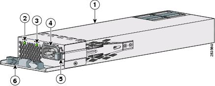
|
|
1100-W AC power supply module |
|
AC power cord connector |
|
|
AC OK LED |
|
Release latch |
|
|
PS OK LED |
|
Power cord retainer |
Figure 3-2 715-W AC Power Supply Module
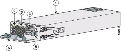
|
|
715-W AC power supply module |
|
AC power cord connector |
|
|
AC OK LED |
|
Release latch |
|
|
PS OK LED |
|
Power cord retainer |
Figure 3-3 350-W AC Power Supply Module
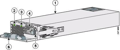
|
|
350-W AC power supply module |
|
AC power cord connector |
|
|
AC OK LED |
|
Release latch |
|
|
PS OK LED |
|
Power cord retainer |
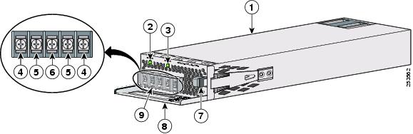
Figure 3-4 440-W DC Power Supply Module
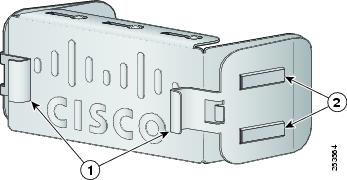
If no power supply is installed in a power supply slot, install a power supply slot cover (Figure 3-5).
Figure 3-5 Power Supply Slot Cover
|
|
Release handles |
|
Retainer clips |
The power supply modules have two status LEDs.
Installation Guidelines
Table 1-16 lists the switches and the compatible power-supply modules. Observe these guidelines when removing or installing a power supply or fan module:
•![]() Do not force the power supply or fan module into the slot. This can damage the pins on the switch if they are not aligned with the module.
Do not force the power supply or fan module into the slot. This can damage the pins on the switch if they are not aligned with the module.
•![]() A power supply or fan module that is only partially connected to the switch can disrupt the system operation.
A power supply or fan module that is only partially connected to the switch can disrupt the system operation.
•![]() Remove power from the power-supply module before removing or installing the module.
Remove power from the power-supply module before removing or installing the module.
•![]() The power supply is hot-swappable. In some configurations, such as full PoE+ or power sharing mode, removing a power supply causes powered devices to shut down until the power budget matches the input power of a single power supply. To minimize network interruption, hot swap the power supply under these circumstances:
The power supply is hot-swappable. In some configurations, such as full PoE+ or power sharing mode, removing a power supply causes powered devices to shut down until the power budget matches the input power of a single power supply. To minimize network interruption, hot swap the power supply under these circumstances:
–![]() The switch is connected to an XPS 2200 and sufficient power is available.
The switch is connected to an XPS 2200 and sufficient power is available.
–![]() The switch is in StackPower mode and sufficient power is available (Catalyst 3750-X only).
The switch is in StackPower mode and sufficient power is available (Catalyst 3750-X only).
–![]() The switch is powered by other switches in a power stack, and no active backup is in progress.
The switch is powered by other switches in a power stack, and no active backup is in progress.
For the switch commands for displaying the available power budget, see the Catalyst 3750-X and 3560-X Software Configuration Guide.

•![]() The switch supports hot swapping of a fan module. When replacing a fan, you should complete the replacement procedure within 5 minutes to avoid overheating the switch.
The switch supports hot swapping of a fan module. When replacing a fan, you should complete the replacement procedure within 5 minutes to avoid overheating the switch.
•![]() The switch continues to operate when there is one failed chassis cooling fan. If one fan fails, the switch sends an error message. If a second fan fails, the switch sends an error message, writes a failure log to flash memory, and shuts down.
The switch continues to operate when there is one failed chassis cooling fan. If one fan fails, the switch sends an error message. If a second fan fails, the switch sends an error message, writes a failure log to flash memory, and shuts down.
•![]() Make sure that all power supply and fan modules are securely seated before moving the switch.
Make sure that all power supply and fan modules are securely seated before moving the switch.
 |
Warning |
|
Warning |
|
Warning |
Statement 371—Power Cable and AC Adapter

Installing an AC Power Supply
Step 1 ![]() Turn off the power at its source.
Turn off the power at its source.
Step 2 ![]() Remove the power cord from the power cord retainer.
Remove the power cord from the power cord retainer.
Step 3 ![]() Remove the power cord from the power connector.
Remove the power cord from the power connector.
Step 4 ![]() Press the release latch at the right side of the power supply module inward and slide the power supply out. (Figure 3-6).
Press the release latch at the right side of the power supply module inward and slide the power supply out. (Figure 3-6).
Step 5 ![]() Insert the new power supply into the power-supply slot, and gently push it into the slot (Figure 3-6). When correctly inserted, the 350-W and 715-W power supplies (excluding the power cord retainer) are flush with the switch rear panel. The 1100-W power-supply module extends 1.5 inches from the switch rear panel.
Insert the new power supply into the power-supply slot, and gently push it into the slot (Figure 3-6). When correctly inserted, the 350-W and 715-W power supplies (excluding the power cord retainer) are flush with the switch rear panel. The 1100-W power-supply module extends 1.5 inches from the switch rear panel.
Figure 3-6 Inserting the AC-Power Supply in the Switch

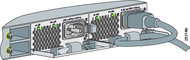
Step 6 ![]() (Optional) Make a loop in the power cord and thread it through the power cord retainer (Figure 3-7).
(Optional) Make a loop in the power cord and thread it through the power cord retainer (Figure 3-7).
Figure 3-7 AC-Power Supply with Power Cord Retainer
Step 7 ![]() Connect the power cord to the power supply and to an AC power outlet. Turn on the power at the power source.
Connect the power cord to the power supply and to an AC power outlet. Turn on the power at the power source.
Step 8 ![]() Confirm that the power supply AC OK and PS OK LEDs are green. See Table 1-19 for a description of the power supply module LEDs.
Confirm that the power supply AC OK and PS OK LEDs are green. See Table 1-19 for a description of the power supply module LEDs.
Installing a DC Power Supply
•![]() Installing the DC Power Supply in the Switch
Installing the DC Power Supply in the Switch
•![]() Wiring the DC Input Power Source
Wiring the DC Input Power Source
|
Warning |
|
Warning |
|
Warning |
Note ![]() The grounding architecture of this product is DC-isolated (DC-I)
The grounding architecture of this product is DC-isolated (DC-I)
Equipment That You Need
•![]() Ratcheting torque screwdriver with a number-2 Phillips head that exerts up to 15 pound-force inches (lbf-in.) of pressure.
Ratcheting torque screwdriver with a number-2 Phillips head that exerts up to 15 pound-force inches (lbf-in.) of pressure.
•![]() Panduit crimping tool with optional controlled-cycle mechanism (model CT-720, CT-920, CT-920CH, CT-930, or CT-940CH).
Panduit crimping tool with optional controlled-cycle mechanism (model CT-720, CT-920, CT-920CH, CT-930, or CT-940CH).
•![]() Wire-stripping tools.
Wire-stripping tools.
•![]() 12-gauge copper ground wire (insulated or not) for a single-ground connection.
12-gauge copper ground wire (insulated or not) for a single-ground connection.
•![]() 8-gauge copper ground wire (insulated or not) for a dual-ground connection.
8-gauge copper ground wire (insulated or not) for a dual-ground connection.
•![]() Ground lug screw and ring lug connector. For a dual-ground connection, use a dual-ground adaptor and dual lug connector.
Ground lug screw and ring lug connector. For a dual-ground connection, use a dual-ground adaptor and dual lug connector.
•![]() Four leads of 14-gauge copper wire.
Four leads of 14-gauge copper wire.
•![]() Four fork-type terminals from the DC power supply accessory kit. The terminals must be the proper size for M3 screws in a Dinkle DT-35-B25-style terminal block.
Four fork-type terminals from the DC power supply accessory kit. The terminals must be the proper size for M3 screws in a Dinkle DT-35-B25-style terminal block.
Grounding the Switch
Follow the grounding procedures at your site and observe these warnings:
|
Warning |
Follow these steps to install either a single-ground lug or a dual-ground lug on the switch. Make sure to follow any grounding requirements at your site.
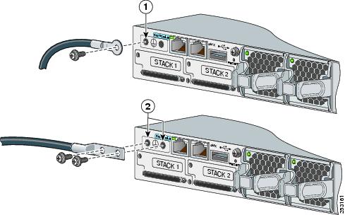
Step 1 ![]() Use the ground lug screw and the lug ring for a single-ground connection. Use the dual-ground adaptor and dual-hole lug for a dual-ground connection.
Use the ground lug screw and the lug ring for a single-ground connection. Use the dual-ground adaptor and dual-hole lug for a dual-ground connection.
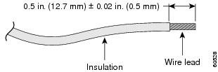
Step 2 ![]() Strip the 12-gauge or 8-gauge ground wire to 0.5 inch (12.7 mm) ± 0.02 inch (0.5 mm) (Figure 3-8). Stripping more than the recommended amount of wire can leave exposed wire from the connector. Use 12-gauge copper ground wire for the single-ground connection. Use 8-gauge copper ground wire for the dual-ground connection.
Strip the 12-gauge or 8-gauge ground wire to 0.5 inch (12.7 mm) ± 0.02 inch (0.5 mm) (Figure 3-8). Stripping more than the recommended amount of wire can leave exposed wire from the connector. Use 12-gauge copper ground wire for the single-ground connection. Use 8-gauge copper ground wire for the dual-ground connection.
Figure 3-8 Stripping the Ground Wire
Step 3 ![]() Slide the open end of the ground lug over the exposed area of the wire.
Slide the open end of the ground lug over the exposed area of the wire.
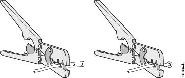
Step 4 ![]() Using a Panduit crimping tool, crimp the ground lug to the wire (Figure 3-9).
Using a Panduit crimping tool, crimp the ground lug to the wire (Figure 3-9).
Figure 3-9 Crimping the Ground Lug
Step 5 ![]() Use the ground screw to attach the single-ground lug to the switch rear panel. Use two ground screws to attach the dual-hole lug to the switch rear panel (Figure 3-10).
Use the ground screw to attach the single-ground lug to the switch rear panel. Use two ground screws to attach the dual-hole lug to the switch rear panel (Figure 3-10).
Step 6 ![]() Using a ratcheting torque screwdriver, torque the ground-lug screws to 60 lbf-in. (960 ozf-in.).
Using a ratcheting torque screwdriver, torque the ground-lug screws to 60 lbf-in. (960 ozf-in.).
Step 7 ![]() Connect the other end of the grounding wire to an appropriate grounding point at your site or to the rack.
Connect the other end of the grounding wire to an appropriate grounding point at your site or to the rack.
Figure 3-10 Attaching the Ground Lug and Wire Assembly
|
|
Single-ground screw and lug ring |
|
Dual-ground adaptor and dual-hole lug |
Installing the DC Power Supply in the Switch
See the Installation Guidelines.
Step 1 ![]() Turn off DC power. To ensure that power is off, change the circuit breakers to the OFF position, and tape the circuit-breaker switches in the OFF position.
Turn off DC power. To ensure that power is off, change the circuit breakers to the OFF position, and tape the circuit-breaker switches in the OFF position.
Step 2 ![]() Remove the plastic safety cover from the power supply terminal blocks (Figure 3-4).
Remove the plastic safety cover from the power supply terminal blocks (Figure 3-4).
If you are not replacing a DC power supply, go to Step 5.
Step 3 ![]() Use a number-2 Phillips screwdriver to remove the DC-input power wires from the power terminals.
Use a number-2 Phillips screwdriver to remove the DC-input power wires from the power terminals.
Step 4 ![]() Press the release latch at the right side of the power supply module inward, and pull the power supply out.
Press the release latch at the right side of the power supply module inward, and pull the power supply out.
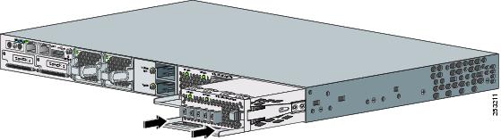
Step 5 ![]() Insert the power supply in the power-supply slot, and gently push it into the slot (Figure 3-11). When correctly installed, the DC power supply (excluding the extraction handle) is flush with the switch rear panel.
Insert the power supply in the power-supply slot, and gently push it into the slot (Figure 3-11). When correctly installed, the DC power supply (excluding the extraction handle) is flush with the switch rear panel.
Figure 3-11 Inserting the DC Power Supply in the Switch
Step 6 ![]() Connect the input power as described in the "Wiring the DC Input Power Source" section.
Connect the input power as described in the "Wiring the DC Input Power Source" section.
Wiring the DC Input Power Source
Step 1 ![]() Using a wire-stripping tool, strip each of the four wires from the DC-input power source to the appropriate length for the terminals.
Using a wire-stripping tool, strip each of the four wires from the DC-input power source to the appropriate length for the terminals.
|
Warning |
Step 2 ![]() Using a Panduit crimping tool, crimp the fork-type terminals to the copper conductor, 90C, 14-AWG DC power input wires.
Using a Panduit crimping tool, crimp the fork-type terminals to the copper conductor, 90C, 14-AWG DC power input wires.
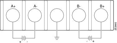
Step 3 ![]() Connect the DC-input power terminals to the terminal blocks. See Figure 3-12 or Figure 3-13. Make sure to match the polarity (negative to negative, positive to positive) when connecting the wires to the terminal blocks. Connect the ground wire to a grounded metal rack or to earth ground if the switch is not in a grounded rack.
Connect the DC-input power terminals to the terminal blocks. See Figure 3-12 or Figure 3-13. Make sure to match the polarity (negative to negative, positive to positive) when connecting the wires to the terminal blocks. Connect the ground wire to a grounded metal rack or to earth ground if the switch is not in a grounded rack.
Figure 3-12 DC Source A Isolated From Source B with No Common Ground
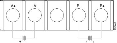
Figure 3-13 DC Source A and Source B Connections with Common Ground
Step 4 ![]() Torque all terminal block screws to 11 lbf-in.
Torque all terminal block screws to 11 lbf-in.
Step 5 ![]() Replace the terminal block safety cover.
Replace the terminal block safety cover.
Step 6 ![]() Move the DC power source circuit-breakers to the ON position.
Move the DC power source circuit-breakers to the ON position.
Step 7 ![]() Confirm that the power-supply DC OK and PS OK LEDs are green. See Table 3-2 for a description of the module LEDs.
Confirm that the power-supply DC OK and PS OK LEDs are green. See Table 3-2 for a description of the module LEDs.
Finding the Power Supply Module Serial Number
If you contact Cisco Technical Assistance regarding a power supply module, you need to know the serial number. See Figure 3-14 to Figure 3-16 to find the serial number.
Figure 3-14 1100-W AC Power Supply Serial Number

Figure 3-15 715-W and 350-W AC Power Supply Module Serial Number

Figure 3-16 440-W DC Power Supply Module Serial Number

Fan Module Overview
The switch has two fan modules. Each fan module contains two fans. Fan modules are hot-swappable.
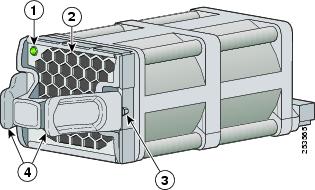
Figure 3-17 Fan Module
|
|
Fan LED |
|
Retainer clip |
|
|
Exhaust vent |
|
Extraction handles |
Installing a Fan Module
Note ![]() There must be a fan module in both fan module slots.
There must be a fan module in both fan module slots.
Step 1 ![]() Pinch the fan release handle, and slide the fan out.
Pinch the fan release handle, and slide the fan out.
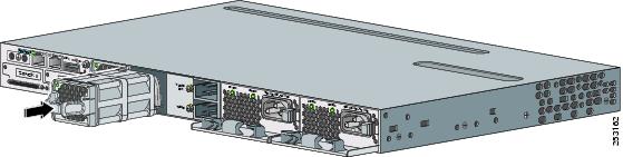
Step 2 ![]() Insert the new fan module into the fan slot, and firmly push the module) into the slot, applying pressure to the end of the module, not the extraction handles (Figure 3-18). When correctly inserted, the fan module is flush with the switch rear panel. When the fan is operating, a green LED is on in the top left corner of the fan.
Insert the new fan module into the fan slot, and firmly push the module) into the slot, applying pressure to the end of the module, not the extraction handles (Figure 3-18). When correctly inserted, the fan module is flush with the switch rear panel. When the fan is operating, a green LED is on in the top left corner of the fan.
|
Warning |
Figure 3-18 Inserting the Fan Module in the Switch
Finding the Fan Module Serial Number
If you contact Cisco Technical Assistance regarding a fan module, you need to know the fan module serial number. See Figure 3-19 for the serial number location.
Figure 3-19 Fan Module Serial Number

 Feedback