- Finding Feature Information
- Information About Configuring IP Unicast Routing
- Information About IP Routing
- How to Configure IP Routing
- How to Configure IP Addressing
- BGP Network Topology
- Nonstop Forwarding Awareness
- Information About BGP Routing
- Routing Policy Changes
- BGP Decision Attributes
- Route Maps
- BGP Filtering
- Prefix List for BGP Filtering
- BGP Community Filtering
- BGP Neighbors and Peer Groups
- Aggregate Routes
- Routing Domain Confederations
- BGP Route Reflectors
- Route Dampening
- More BGP Information
- Default BGP Configuration
- Enabling BGP Routing
- Managing Routing Policy Changes
- Configuring BGP Decision Attributes
- Configuring BGP Filtering with Route Maps
- Configuring BGP Filtering by Neighbor
- Configuring BGP Filtering by Access Lists and Neighbors
- Configuring Prefix Lists for BGP Filtering
- Configuring BGP Community Filtering
- Configuring BGP Neighbors and Peer Groups
- Configuring Aggregate Addresses in a Routing Table
- Configuring Routing Domain Confederations
- Configuring BGP Route Reflectors
- Configuring Route Dampening
- Default Multi-VRF CE Configuration
- Multi-VRF CE Configuration Guidelines
- Configuring VRFs
- Configuring VRF-Aware Services
- Configuring VRF-Aware Services for ARP
- Configuring VRF-Aware Services for Ping
- Configuring VRF-Aware Services for SNMP
- Configuring VRF-Aware Servcies for uRPF
- Configuring VRF-Aware RADIUS
- Configuring VRF-Aware Services for Syslog
- Configuring VRF-Aware Services for Traceroute
- Configuring VRF-Aware Services for FTP and TFTP
- Configuring Multicast VRFs
- Configuring a VPN Routing Session
- Configuring BGP PE to CE Routing Sessions
- Monitoring Multi-VRF CE
Configuring IP Unicast Routing
- Finding Feature Information
- Information About Configuring IP Unicast Routing
- Information About IP Routing
- How to Configure IP Routing
- How to Configure IP Addressing
- Monitoring and Maintaining IP Addressing
- How to Configure IP Unicast Routing
- Information About RIP
- How to Configure RIP
- Configuration Example for Summary Addresses and Split Horizon
- Information About OSPF
- How to Configure OSPF
- Monitoring OSPF
- Configuration Examples for OSPF
- Information About EIGRP
- How to Configure EIGRP
- Monitoring and Maintaining EIGRP
- Information About BGP
- How to Configure BGP
- Monitoring and Maintaining BGP
- Configuration Examples for BGP
- Information About ISO CLNS Routing
- How to Configure ISO CLNS Routing
- Monitoring and Maintaining ISO IGRP and IS-IS
- Configuration Examples for ISO CLNS Routing
- Information About Multi-VRF CE
- How to Configure Multi-VRF CE
- Configuration Examples for Multi-VRF CE
- Configuring Unicast Reverse Path Forwarding
- Protocol-Independent Features
- Monitoring and Maintaining the IP Network
Finding Feature Information
Your software release may not support all the features documented in this module. For the latest feature information and caveats, see the release notes for your platform and software release.
Use Cisco Feature Navigator to find information about platform support and Cisco software image support. To access Cisco Feature Navigator, go to http://www.cisco.com/go/cfn. An account on Cisco.com is not required.
Information About Configuring IP Unicast Routing
This module describes how to configure IP Version 4 (IPv4) unicast routing on the switch.
 Note |
On switches running the LAN base feature, static routing on VLANs is supported only with this release. |
A switch stack operates and appears as a single router to the rest of the routers in the network. Basic routing functions, including static routing and the Routing Information Protocol (RIP), are available with both the IP base feature set and the IP services feature set. To use advanced routing features and other routing protocols, you must have the IP services feature set enabled on the standalone switch or on the active switch.
Information About IP Routing
In some network environments, VLANs are associated with individual networks or subnetworks. In an IP network, each subnetwork is mapped to an individual VLAN. Configuring VLANs helps control the size of the broadcast domain and keeps local traffic local. However, network devices in different VLANs cannot communicate with one another without a Layer 3 device (router) to route traffic between the VLAN, referred to as inter-VLAN routing. You configure one or more routers to route traffic to the appropriate destination VLAN.
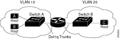
When Host A in VLAN 10 needs to communicate with Host B in VLAN 10, it sends a packet addressed to that host. Switch A forwards the packet directly to Host B, without sending it to the router.
When Host A sends a packet to Host C in VLAN 20, Switch A forwards the packet to the router, which receives the traffic on the VLAN 10 interface. The router checks the routing table, finds the correct outgoing interface, and forwards the packet on the VLAN 20 interface to Switch B. Switch B receives the packet and forwards it to Host C.
- Types of Routing
- IP Routing and Switch Stacks
- Classless Routing
- Address Resolution
- Proxy ARP
- ICMP Router Discovery Protocol
- Broadcast Packet Handling
- IP Broadcast Flooding
Types of Routing
Routers and Layer 3 switches can route packets in these ways:
- By using default routing
- By using preprogrammed static routes for the traffic
- By dynamically calculating routes by using a routing protocol
Default routing refers to sending traffic with a destination unknown to the router to a default outlet or destination.
Static unicast routing forwards packets from predetermined ports through a single path into and out of a network. Static routing is secure and uses little bandwidth, but does not automatically respond to changes in the network, such as link failures, and therefore, might result in unreachable destinations. As networks grow, static routing becomes a labor-intensive liability.
Switches running the LAN base feature set support 16 user-configured static routes, in addition to any default routes used for the management interface. The LAN base image supports static routing only on SVIs.
Dynamic routing protocols are used by routers to dynamically calculate the best route for forwarding traffic. There are two types of dynamic routing protocols:
- Routers using distance-vector protocols maintain routing tables with distance values of networked resources, and periodically pass these tables to their neighbors. Distance-vector protocols use one or a series of metrics for calculating the best routes. These protocols are easy to configure and use.
- Routers using link-state protocols maintain a complex database of network topology, based on the exchange of link-state advertisements (LSAs) between routers. LSAs are triggered by an event in the network, which speeds up the convergence time or time required to respond to these changes. Link-state protocols respond quickly to topology changes, but require greater bandwidth and more resources than distance-vector protocols.
Distance-vector protocols supported by the switch are Routing Information Protocol (RIP), which uses a single distance metric (cost) to determine the best path and Border Gateway Protocol (BGP), which adds a path vector mechanism. The switch also supports the Open Shortest Path First (OSPF) link-state protocol and Enhanced IGRP (EIGRP), which adds some link-state routing features to traditional Interior Gateway Routing Protocol (IGRP) to improve efficiency.
IP Routing and Switch Stacks
A switch stack appears to the network as a single switch, regardless of which switch in the stack is connected to a routing peer.
The active switch performs these functions:
- It initializes and configures the routing protocols.
- It sends routing protocol messages and updates to other routers.
- It processes routing protocol messages and updates received from peer routers.
- It generates, maintains, and distributes the distributed Cisco Express Forwarding (dCEF) database to all stack members. The routes are programmed on all switches in the stack bases on this database.
- The MAC address of the active switch is used as the router MAC address for the whole stack, and all outside devices use this address to send IP packets to the stack.
- All IP packets that require software forwarding or processing go through the CPU of the active switch.
Stack members perform these functions:
- They act as routing standby switches, ready to take over in case they are elected as the new active switch if the active switch fails.
- They program the routes into hardware.
If a active switch fails, the stack detects that the active switch is down and elects one of the stack members to be the new active switch. During this period, except for a momentary interruption, the hardware continues to forward packets with no active protocols.
However, even though the switch stack maintains the hardware identification after a failure, the routing protocols on the router neighbors might flap during the brief interruption before the active switch restarts. Routing protocols such as OSPF and EIGRP need to recognize neighbor transitions. The router uses two levels of nonstop forwarding (NSF) to detect a switchover, to continue forwarding network traffic, and to recover route information from peer devices:
- NSF-aware routers tolerate neighboring router failures. After the neighbor router restarts, an NSF-aware router supplies information about its state and route adjacencies on request.
- NSF-capable routers support NSF. When they detect a active switch change, they rebuild routing information from NSF-aware or NSF-capable neighbors and do not wait for a restart.
The switch stack supports NSF-capable routing for OSPF and EIGRP.
Upon election, the new active switch performs these functions:
- It starts generating, receiving, and processing routing updates.
- It builds routing tables, generates the CEF database, and distributes it to stack members.
- It uses its MAC address as the router MAC address. To notify its network peers of the new MAC address, it periodically (every few seconds for 5 minutes) sends a gratuitous ARP reply with the new router MAC address.
-
It attempts to determine the reachability of every proxy ARP entry by sending an ARP request to the proxy ARP IP address and receiving an ARP reply. For each reachable proxy ARP IP address, it generates a gratuitous ARP reply with the new router MAC address. This process is repeated for 5 minutes after a new active switch election.

Caution
Partitioning of the switch stack into two or more stacks might lead to undesirable behavior in the network.
If the switch is reloaded, then all the ports on that switch go down and there is a loss of traffic for the interfaces involved in routing, despite NSF/SSO capability
Classless Routing
By default, classless routing behavior is enabled on the switch when it is configured to route. With classless routing, if a router receives packets for a subnet of a network with no default route, the router forwards the packet to the best supernet route. A supernet consists of contiguous blocks of Class C address spaces used to simulate a single, larger address space and is designed to relieve the pressure on the rapidly depleting Class B address space.
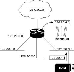
In Figure 41-2, classless routing is enabled. When the host sends a packet to 120.20.4.1, instead of discarding the packet, the router forwards it to the best supernet route. If you disable classless routing and a router receives packets destined for a subnet of a network with no network default route, the router discards the packet.
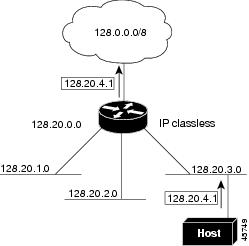
In Figure 41-3, the router in network 128.20.0.0 is connected to subnets 128.20.1.0, 128.20.2.0, and 128.20.3.0. If the host sends a packet to 120.20.4.1, because there is no network default route, the router discards the packet.
Address Resolution
You can control interface-specific handling of IP by using address resolution. A device using IP can have both a local address or MAC address, which uniquely defines the device on its local segment or LAN, and a network address, which identifies the network to which the device belongs.
Note |
In a switch stack, network communication uses a single MAC address and the IP address of the stack. |
The local address or MAC address is known as a data link address because it is contained in the data link layer (Layer 2) section of the packet header and is read by data link (Layer 2) devices. To communicate with a device on Ethernet, the software must learn the MAC address of the device. The process of learning the MAC address from an IP address is called address resolution. The process of learning the IP address from the MAC address is called reverse address resolution.
The switch can use these forms of address resolution:
- Address Resolution Protocol (ARP) is used to associate IP address with MAC addresses. Taking an IP address as input, ARP learns the associated MAC address and then stores the IP address/MAC address association in an ARP cache for rapid retrieval. Then the IP datagram is encapsulated in a link-layer frame and sent over the network. Encapsulation of IP datagrams and ARP requests or replies on IEEE 802 networks other than Ethernet is specified by the Subnetwork Access Protocol (SNAP).
- Proxy ARP helps hosts with no routing tables learn the MAC addresses of hosts on other networks or subnets. If the switch (router) receives an ARP request for a host that is not on the same interface as the ARP request sender, and if the router has all of its routes to the host through other interfaces, it generates a proxy ARP packet giving its own local data link address. The host that sent the ARP request then sends its packets to the router, which forwards them to the intended host.
The switch also uses the Reverse Address Resolution Protocol (RARP), which functions the same as ARP does, except that the RARP packets request an IP address instead of a local MAC address. Using RARP requires a RARP server on the same network segment as the router interface. Use the ip rarp-server address interface configuration command to identify the server.
For more information on RARP, see the Cisco IOS Configuration Fundamentals Configuration Guide, Release 12.4.
Proxy ARP
Proxy ARP, the most common method for learning about other routes, enables an Ethernet host with no routing information to communicate with hosts on other networks or subnets. The host assumes that all hosts are on the same local Ethernet and that they can use ARP to learn their MAC addresses. If a switch receives an ARP request for a host that is not on the same network as the sender, the switch evaluates whether it has the best route to that host. If it does, it sends an ARP reply packet with its own Ethernet MAC address, and the host that sent the request sends the packet to the switch, which forwards it to the intended host. Proxy ARP treats all networks as if they are local and performs ARP requests for every IP address.
ICMP Router Discovery Protocol
Router discovery allows the switch to dynamically learn about routes to other networks using ICMP router discovery protocol (IRDP). IRDP allows hosts to locate routers. When operating as a client, the switch generates router discovery packets. When operating as a host, the switch receives router discovery packets. The switch can also listen to Routing Information Protocol (RIP) routing updates and use this information to infer locations of routers. The switch does not actually store the routing tables sent by routing devices; it merely keeps track of which systems are sending the data. The advantage of using IRDP is that it allows each router to specify both a priority and the time after which a device is assumed to be down if no further packets are received.
Each device discovered becomes a candidate for the default router, and a new highest-priority router is selected when a higher priority router is discovered, when the current default router is declared down, or when a TCP connection is about to time out because of excessive retransmissions.
UDP Broadcast Packets and Protocols
User Datagram Protocol (UDP) is an IP host-to-host layer protocol, as is TCP. UDP provides a low-overhead, connectionless session between two end systems and does not provide for acknowledgment of received datagrams. Network hosts occasionally use UDP broadcasts to find address, configuration, and name information. If such a host is on a network segment that does not include a server, UDP broadcasts are normally not forwarded. You can remedy this situation by configuring an interface on a router to forward certain classes of broadcasts to a helper address. You can use more than one helper address per interface.
You can specify a UDP destination port to control which UDP services are forwarded. You can specify multiple UDP protocols. You can also specify the Network Disk (ND) protocol, which is used by older diskless Sun workstations and the network security protocol SDNS.
By default, both UDP and ND forwarding are enabled if a helper address has been defined for an interface. The description for the ip forward-protocol interface configuration command in the Cisco IOS IP Command Reference, Volume 1 of 3: Addressing and Services, Release 12.4 lists the ports that are forwarded by default if you do not specify any UDP ports.
Broadcast Packet Handling
After configuring an IP interface address, you can enable routing and configure one or more routing protocols, or you can configure the way the switch responds to network broadcasts. A broadcast is a data packet destined for all hosts on a physical network. The switch supports two kinds of broadcasting:
- A directed broadcast packet is sent to a specific network or series of networks. A directed broadcast address includes the network or subnet fields.
-
A flooded broadcast packet is sent to every network.
Note
You can also limit broadcast, unicast, and multicast traffic on Layer 2 interfaces by using the storm-control interface configuration command to set traffic suppression levels.
Routers provide some protection from broadcast storms by limiting their extent to the local cable. Bridges (including intelligent bridges), because they are Layer 2 devices, forward broadcasts to all network segments, thus propagating broadcast storms. The best solution to the broadcast storm problem is to use a single broadcast address scheme on a network. In most modern IP implementations, you can set the address to be used as the broadcast address. Many implementations, including the one in the switch, support several addressing schemes for forwarding broadcast messages.
IP Broadcast Flooding
You can allow IP broadcasts to be flooded throughout your internetwork in a controlled fashion by using the database created by the bridging STP. Using this feature also prevents loops. To support this capability, bridging must be configured on each interface that is to participate in the flooding. If bridging is not configured on an interface, it still can receive broadcasts. However, the interface never forwards broadcasts it receives, and the router never uses that interface to send broadcasts received on a different interface.
Packets that are forwarded to a single network address using the IP helper-address mechanism can be flooded. Only one copy of the packet is sent on each network segment.
To be considered for flooding, packets must meet these criteria. (Note that these are the same conditions used to consider packet forwarding using IP helper addresses.)
- The packet must be a MAC-level broadcast.
- The packet must be an IP-level broadcast.
- The packet must be a TFTP, DNS, Time, NetBIOS, ND, or BOOTP packet, or a UDP specified by the ip forward-protocol udp global configuration command.
- The time-to-live (TTL) value of the packet must be at least two.
A flooded UDP datagram is given the destination address specified with the ip broadcast-address interface configuration command on the output interface. The destination address can be set to any address. Thus, the destination address might change as the datagram propagates through the network. The source address is never changed. The TTL value is decremented.
When a flooded UDP datagram is sent out an interface (and the destination address possibly changed), the datagram is handed to the normal IP output routines and is, therefore, subject to access lists, if they are present on the output interface.
In the switch, the majority of packets are forwarded in hardware; most packets do not go through the switch CPU. For those packets that do go to the CPU, you can speed up spanning tree-based UDP flooding by a factor of about four to five times by using turbo-flooding. This feature is supported over Ethernet interfaces configured for ARP encapsulation.
How to Configure IP Routing
By default, IP routing is disabled on the switch, and you must enable it before routing can take place. For detailed IP routing configuration information, see the Cisco IOS IP Configuration Guide, Release 12.4
In the following procedures, the specified interface must be one of these Layer 3 interfaces:
- A routed port: a physical port configured as a Layer 3 port by using the no switchport interface configuration command.
- A switch virtual interface (SVI): a VLAN interface created by using the interface vlan vlan_id global configuration command and by default a Layer 3 interface.
-
An EtherChannel port channel in Layer 3 mode: a port-channel logical interface created by using the
interface port-channel
port-channel-number global configuration command and binding the Ethernet interface into the channel group. For more information, see the “Configuring Layer 3 EtherChannels” section on page 39-15.
Note
The switch does not support tunnel interfaces for unicast routed traffic.
All Layer 3 interfaces on which routing will occur must have IP addresses assigned to them. See the “Assigning IP Addresses to Network Interfaces” section on page 41-7.
Configuring routing consists of several main procedures:
- To support VLAN interfaces, create and configure VLANs on the switch or switch stack, and assign VLAN membership to Layer 2 interfaces. For more information, see Chapter 14, “Configuring VLANs.”
- Configure Layer 3 interfaces.
- Enable IP routing on the switch.
- Assign IP addresses to the Layer 3 interfaces.
- Enable selected routing protocols on the switch.
- Configure routing protocol parameters (optional).
How to Configure IP Addressing
A required task for configuring IP routing is to assign IP addresses to Layer 3 network interfaces to enable the interfaces and allow communication with the hosts on those interfaces that use IP. The following sections describe how to configure various IP addressing features. Assigning IP addresses to the interface is required; the other procedures are optional.
- Default IP Addressing Configuration
- Assigning IP Addresses to Network Interfaces
- Configuring Address Resolution Methods
- Routing Assistance When IP Routing is Disabled
- Configuring Broadcast Packet Handling
Default IP Addressing Configuration
Assigning IP Addresses to Network Interfaces
An IP address identifies a location to which IP packets can be sent. Some IP addresses are reserved for special uses and cannot be used for host, subnet, or network addresses. RFC 1166, “Internet Numbers,” contains the official description of IP addresses.
An interface can have one primary IP address. A mask identifies the bits that denote the network number in an IP address. When you use the mask to subnet a network, the mask is referred to as a subnet mask. To receive an assigned network number, contact your Internet service provider.
Using Subnet Zero
Subnetting with a subnet address of zero is strongly discouraged because of the problems that can arise if a network and a subnet have the same addresses. For example, if network 131.108.0.0 is subnetted as 255.255.255.0, subnet zero would be written as 131.108.0.0, which is the same as the network address.
You can use the all ones subnet (131.108.255.0) and even though it is discouraged, you can enable the use of subnet zero if you need the entire subnet space for your IP address.
Enabling Classless Routing
To prevent the switch from forwarding packets destined for unrecognized subnets to the best supernet route possible, you can disable classless routing behavior.
Configuring Address Resolution Methods
You can perform the following tasks to configure address resolution.
Defining a Static ARP Cache
ARP and other address resolution protocols provide dynamic mapping between IP addresses and MAC addresses. Because most hosts support dynamic address resolution, you usually do not need to specify static ARP cache entries. If you must define a static ARP cache entry, you can do so globally, which installs a permanent entry in the ARP cache that the switch uses to translate IP addresses into MAC addresses. Optionally, you can also specify that the switch respond to ARP requests as if it were the owner of the specified IP address. If you do not want the ARP entry to be permanent, you can specify a timeout period for the ARP entry.
Setting ARP Encapsulation
By default, Ethernet ARP encapsulation (represented by the arpa keyword) is enabled on an IP interface. You can change the encapsulation methods to SNAP if required by your network.
Enabling Proxy ARP
By default, the switch uses proxy ARP to help hosts learn MAC addresses of hosts on other networks or subnets.
Routing Assistance When IP Routing is Disabled
These mechanisms allow the switch to learn about routes to other networks when it does not have IP routing enabled:
Proxy ARP
Proxy ARP is enabled by default. To enable it after it has been disabled, see the “Enabling Proxy ARP” section. Proxy ARP works as long as other routers support it.
Default Gateway
Another method for locating routes is to define a default router or default gateway. All non-local packets are sent to this router, which either routes them appropriately or sends an IP Control Message Protocol (ICMP) redirect message back, defining which local router the host should use. The switch caches the redirect messages and forwards each packet as efficiently as possible. A limitation of this method is that there is no means of detecting when the default router has gone down or is unavailable.
ICMP Router Discovery Protocol (IRDP)
The only required task for IRDP routing on an interface is to enable IRDP processing on that interface. When enabled, the default parameters apply.
You can optionally change any of these parameters. If you change the maxadvertinterval value, the holdtime and minadvertinterval values also change, so it is important to first change the maxadvertinterval value, before manually changing either the holdtime or minadvertinterval values.
Configuring Broadcast Packet Handling
Perform the tasks in these sections to enable these schemes:
- Enabling Directed Broadcast-to-Physical Broadcast Translation
- Forwarding UDP Broadcast Packets and Protocols
- Establishing an IP Broadcast Address
- Flooding IP Broadcasts
Enabling Directed Broadcast-to-Physical Broadcast Translation
By default, IP directed broadcasts are dropped; they are not forwarded. Dropping IP-directed broadcasts makes routers less susceptible to denial-of-service attacks.
You can enable forwarding of IP-directed broadcasts on an interface where the broadcast becomes a physical (MAC-layer) broadcast. Only those protocols configured by using the ip forward-protocol global configuration command are forwarded.
You can specify an access list to control which broadcasts are forwarded. When an access list is specified, only those IP packets permitted by the access list are eligible to be translated from directed broadcasts to physical broadcasts. For more information on access lists, see Chapter 36, “Configuring Network Security with ACLs.”
| Command or Action | Purpose | |||
|---|---|---|---|---|
| Step 1 |
configure terminal Example: # configure terminal |
|||
| Step 2 |
interface
interface-id Example: (config)# interface gigabitethernet 1/0/2 |
Enters interface configuration mode, and specifies the interface to configure. |
||
| Step 3 |
ip directed-broadcast [
access-list-number] Example: (config-if)# ip directed-broadcast 103 |
Enables directed broadcast-to-physical broadcast translation on the interface. You can include an access list to control which broadcasts are forwarded. When an access list, only IP packets permitted by the access list can be translated.
|
||
| Step 4 |
exit Example: (config-if)# exit |
|||
| Step 5 |
ip forward-protocol {
udp [
port] |
nd |
sdns} Example: (config)# ip forward-protocol nd |
Specifies which protocols and ports the router forwards when forwarding broadcast packets. |
||
| Step 6 |
end Example: (config)# end |
|||
| Step 7 |
show ip interface [
interface-id] Example: # show ip interface |
Verifies the configuration on the interface or all interfaces |
||
| Step 8 |
show running-config Example: # show running-config |
Verifies the configuration on the interface or all interfaces |
||
| Step 9 |
copy running-config startup-config Example: # copy running-config startup-config |
Forwarding UDP Broadcast Packets and Protocols
If you do not specify any UDP ports when you configure the forwarding of UDP broadcasts, you are configuring the router to act as a BOOTP forwarding agent. BOOTP packets carry DHCP information.
| Command or Action | Purpose | |
|---|---|---|
| Step 1 |
configure terminal Example: # configure terminal |
|
| Step 2 |
interface
interface-id Example: (config)# interface gigabitethernet 1/0/1 |
Enters interface configuration mode, and specifies the Layer 3 interface to configure. |
| Step 3 |
ip helper-address
address Example: (config-if)# ip helper address 10.1.10.1 |
Enables forwarding and specifies the destination address for forwarding UDP broadcast packets, including BOOTP. |
| Step 4 |
exit Example: (config-if)# exit |
|
| Step 5 |
ip forward-protocol {
udp [
port] |
nd |
sdns} Example: (config)# ip forward-protocol sdns |
Specifies which protocols the router forwards when forwarding broadcast packets. |
| Step 6 |
end Example: (config)# end |
|
| Step 7 |
show ip interface [
interface-id] Example: # show ip interface gigabitethernet 1/0/1 |
Verifies the configuration on the interface or all interfaces. |
| Step 8 |
show running-config Example: # show running-config |
Verifies the configuration on the interface or all interfaces. |
| Step 9 |
copy running-config startup-config Example: # copy running-config startup-config |
Establishing an IP Broadcast Address
The most popular IP broadcast address (and the default) is an address consisting of all ones (255.255.255.255). However, the switch can be configured to generate any form of IP broadcast address.
| Command or Action | Purpose | |
|---|---|---|
| Step 1 |
configure terminal Example: # configure terminal |
|
| Step 2 |
interface
interface-id Example: (config)# interface gigabitethernet 1/0/1 |
Enters interface configuration mode, and specifies the interface to configure. |
| Step 3 |
ip broadcast-address
ip-address Example: (config-if)# ip broadcast-address 128.1.255.255 |
Enters a broadcast address different from the default, for example 128.1.255.255. |
| Step 4 |
end Example: (config-if)# end |
|
| Step 5 |
show ip interface [
interface-id] Example: # show ip interface |
Verifies the broadcast address on the interface or all interfaces. |
| Step 6 |
copy running-config startup-config Example: # copy running-config startup-config |
Flooding IP Broadcasts
| Command or Action | Purpose | |
|---|---|---|
| Step 1 |
configure terminal Example: # configure terminal |
|
| Step 2 |
ip forward-protocol spanning-tree Example: (config)# ip forward-protocol spanning-tree |
Uses the bridging spanning-tree database to flood UDP datagrams. |
| Step 3 |
end Example: (config)# end |
|
| Step 4 |
show running-config Example: # show running-config |
|
| Step 5 |
copy running-config startup-config Example: # copy running-config startup-config |
|
| Step 6 |
configure terminal Example: # configure terminal |
|
| Step 7 |
ip forward-protocol turbo-flood Example: (config)# ip forward-protocol turbo-flood |
Uses the spanning-tree database to speed up flooding of UDP datagrams. |
| Step 8 |
end Example: (config)# end |
|
| Step 9 |
show running-config Example: # show running-config |
|
| Step 10 |
copy running-config startup-config Example: # copy running-config startup-config |
Monitoring and Maintaining IP Addressing
When the contents of a particular cache, table, or database have become or are suspected to be invalid, you can remove all its contents by using the clear privileged EXEC commands. Table 41-2 lists the commands for clearing contents.
Removes one or all entries from the hostname and the address cache. |
|
You can display specific statistics, such as the contents of IP routing tables, caches, and databases; the reachability of nodes; and the routing path that packets are taking through the network. Table 41-3 lists the privileged EXEC commands for displaying IP statistics.
Displays the default domain name, style of lookup service, name server hosts, and the cached list of hostnames and addresses. |
|
Displays the masks used for network addresses and the number of subnets using each mask. |
|
Displays the current state of the routing table in summary form. |
How to Configure IP Unicast Routing
Enabling IP Unicast Routing
By default, the switch is in Layer 2 switching mode and IP routing is disabled. To use the Layer 3 capabilities of the switch, you must enable IP routing.
| Command or Action | Purpose | |||
|---|---|---|---|---|
| Step 1 |
configure terminal Example: # configure terminal |
|||
| Step 2 |
ip routing Example: (config)# ip routing |
|||
| Step 3 |
router
ip_routing_protocol Example: (config)# router rip |
Specifies an IP routing protocol. This step might include other commands, such as specifying the networks to route with the network (RIP) router configuration command. For information on specific protocols, see sections later in this chapter and to the Cisco IOS IP Configuration Guide, Release 12.4.
|
||
| Step 4 |
end Example: (config)# end |
|||
| Step 5 |
show running-config Example: # show running-config |
|||
| Step 6 |
copy running-config startup-config Example: # copy running-config startup-config |
Example of Enabling IP Routing
This example shows how to enable IP routingusing RIP as the routing protocol :
# configure terminal
Enter configuration commands, one per line.  End with CNTL/Z.
(config)# ip routing
(config)# router rip
(config-router)# network 10.0.0.0
(config-router)# end
What to Do Next
You can now set up parameters for the selected routing protocols as described in these sections:
Information About RIP
The Routing Information Protocol (RIP) is an interior gateway protocol (IGP) created for use in small, homogeneous networks. It is a distance-vector routing protocol that uses broadcast User Datagram Protocol (UDP) data packets to exchange routing information. The protocol is documented in RFC 1058. You can find detailed information about RIP in IP Routing Fundamentals, published by Cisco Press.
Note |
RIP is supported in the IP Base. |
Using RIP, the switch sends routing information updates (advertisements) every 30 seconds. If a router does not receive an update from another router for 180 seconds or more, it marks the routes served by that router as unusable. If there is still no update after 240 seconds, the router removes all routing table entries for the non-updating router.
RIP uses hop counts to rate the value of different routes. The hop count is the number of routers that can be traversed in a route. A directly connected network has a hop count of zero; a network with a hop count of 16 is unreachable. This small range (0 to 15) makes RIP unsuitable for large networks.
If the router has a default network path, RIP advertises a route that links the router to the pseudonetwork 0.0.0.0. The 0.0.0.0 network does not exist; it is treated by RIP as a network to implement the default routing feature. The switch advertises the default network if a default was learned by RIP or if the router has a gateway of last resort and RIP is configured with a default metric. RIP sends updates to the interfaces in specified networks. If an interface’s network is not specified, it is not advertised in any RIP update.
Summary Addresses and Split Horizon
Routers connected to broadcast-type IP networks and using distance-vector routing protocols normally use the split-horizon mechanism to reduce the possibility of routing loops. Split horizon blocks information about routes from being advertised by a router on any interface from which that information originated. This feature usually optimizes communication among multiple routers, especially when links are broken.
How to Configure RIP
Default RIP Configuration
| Disabled |
|
| Receives RIP Version 1 and 2 packets; sends Version 1 packets. |
Configuring Basic RIP Parameters
To configure RIP, you enable RIP routing for a network and optionally configure other parameters. On the switches, RIP configuration commands are ignored until you configure the network number.
| Command or Action | Purpose | |||
|---|---|---|---|---|
| Step 1 |
configure terminal Example: # configure terminal |
|||
| Step 2 |
ip routing Example: (config)# ip routing |
Enables IP routing. (Required only if IP routing is disabled.) |
||
| Step 3 |
router rip Example: (config)# router rip |
Enables a RIP routing process, and enter router configuration mode. |
||
| Step 4 |
network
network number Example: (config)# network 12 |
Associates a network with a RIP routing process. You can specify multiple network commands. RIP routing updates are sent and received through interfaces only on these networks.
|
||
| Step 5 |
neighbor
ip-address Example: (config)# neighbor 10.2.5.1 |
(Optional) Defines a neighboring router with which to exchange routing information. This step allows routing updates from RIP (normally a broadcast protocol) to reach nonbroadcast networks. |
||
| Step 6 |
offset-list [
access-list number |
name] {
in |
out}
offset [
type number] Example: (config)# offset-list 103 in 10 |
(Optional) Applies an offset list to routing metrics to increase incoming and outgoing metrics to routes learned through RIP. You can limit the offset list with an access list or an interface. |
||
| Step 7 |
timers basic
update invalid holddown flush Example: (config)# timers basic 45 360 400 300 |
(Optional) Adjusts routing protocol timers. Valid ranges for all timers are 0 to 4294967295 seconds.
|
||
| Step 8 |
version {
1 |
2} Example: (config)# version 2 |
(Optional) Configures the switch to receive and send only RIP Version 1 or RIP Version 2 packets. By default, the switch receives Version 1 and 2 but sends only Version 1. You can also use the interface commands ip rip { send | receive} version 1 | 2 | 1 2} to control what versions are used for sending and receiving on interfaces. |
||
| Step 9 |
no auto summary Example: (config)# no auto summary |
(Optional) Disables automatic summarization. By default, the switch summarizes subprefixes when crossing classful network boundaries. Disable summarization (RIP Version 2 only) to advertise subnet and host routing information to classful network boundaries. |
||
| Step 10 |
no validate-update-source Example: (config)# no validdate-update-source |
(Optional) Disables validation of the source IP address of incoming RIP routing updates. By default, the switch validates the source IP address of incoming RIP routing updates and discards the update if the source address is not valid. Under normal circumstances, disabling this feature is not recommended. However, if you have a router that is off-network and you want to receive its updates, you can use this command. |
||
| Step 11 |
output-delay
delay Example: (config)# output-delay 8 |
(Optional) Adds interpacket delay for RIP updates sent. By default, packets in a multiple-packet RIP update have no delay added between packets. If you are sending packets to a lower-speed device, you can add an interpacket delay in the range of 8 to 50 milliseconds. |
||
| Step 12 |
end Example: (config)# end |
|||
| Step 13 |
show ip protocols Example: # show ip protocols |
|||
| Step 14 |
copy running-config startup-config Example: # copy running-config startup-config |
Configuring RIP Authentication
RIP Version 1 does not support authentication. If you are sending and receiving RIP Version 2 packets, you can enable RIP authentication on an interface. The key chain specifies the set of keys that can be used on the interface. If a key chain is not configured, no authentication is performed.
The switch supports two modes of authentication on interfaces for which RIP authentication is enabled: plain text and MD5. The default is plain text.
| Command or Action | Purpose | |
|---|---|---|
| Step 1 |
configure terminal Example: # configure terminal |
|
| Step 2 |
interface
interface-id Example: (config)# interface gigabitethernet 1/0/1 |
Enters interface configuration mode, and specifies the interface to configure. |
| Step 3 |
ip rip authentication key-chain
name-of-chain Example: (config-if)# ip rip authentication key-chain trees |
|
| Step 4 |
ip rip authentication mode {
text |
md5} Example: (config-if)# ip rip authentication mode md5 |
Configures the interface to use plain text authentication (the default) or MD5 digest authentication. |
| Step 5 |
end Example: (config-if)# end |
|
| Step 6 |
show running-config interface [
interface-id] Example: # show running-config |
|
| Step 7 |
copy running-config startup-config Example: # copy running-config startup-config |
Configuring Summary Addresses and Split Horizon
Note |
In general, disabling split horizon is not recommended unless you are certain that your application requires it to properly advertise routes. |
If you want to configure an interface running RIP to advertise a summarized local IP address pool on a network access server for dial-up clients, use the ip summary-address rip interface configuration command.
Note |
If split horizon is enabled, neither autosummary nor interface IP summary addresses are advertised. |
| Command or Action | Purpose | |
|---|---|---|
| Step 1 |
configure terminal Example: # configure terminal |
|
| Step 2 |
interface
interface-id Example: (config)# interface gigabitethernet 1/0/1 |
Enters interface configuration mode, and specifies the Layer 3 interface to configure. |
| Step 3 |
ip address
ip-address subnet-mask Example: (config-if)# ip address 10.1.1.10 255.255.255.0 |
|
| Step 4 |
ip summary-address rip ip address
ip-network mask Example: (config-if)# ip summary-address rip ip address 10.1.1.30 255.255.255.0 |
Configures the IP address to be summarized and the IP network mask. |
| Step 5 |
no ip split horizon Example: (config-if)# no ip split horizon |
|
| Step 6 |
end Example: (config-if)# end |
|
| Step 7 |
show ip interface
interface-id Example: # show ip interface gigabitethernet 1/0/1 |
|
| Step 8 |
copy running-config startup-config Example: # copy running-config startup-config |
Configuring Split Horizon
Routers connected to broadcast-type IP networks and using distance-vector routing protocols normally use the split-horizon mechanism to reduce the possibility of routing loops. Split horizon blocks information about routes from being advertised by a router on any interface from which that information originated. This feature can optimize communication among multiple routers, especially when links are broken.
Note |
In general, we do not recommend disabling split horizon unless you are certain that your application requires it to properly advertise routes. |
| Command or Action | Purpose | |
|---|---|---|
| Step 1 |
configure terminal Example: # configure terminal |
|
| Step 2 |
interface
interface-id Example: (config)# interface gigabitethernet 1/0/1 |
Enters interface configuration mode, and specifies the interface to configure. |
| Step 3 |
ip address
ip-address subnet-mask Example: (config-if)# ip address 10.1.1.10 255.255.255.0 |
|
| Step 4 |
no ip split-horizon Example: (config-if)# no ip split-horizon |
|
| Step 5 |
end Example: (config-if)# end |
|
| Step 6 |
show ip interface
interface-id Example: # show ip interface gigabitethernet 1/0/1 |
|
| Step 7 |
copy running-config startup-config Example: # copy running-config startup-config |
Configuration Example for Summary Addresses and Split Horizon
In this example, the major net is 10.0.0.0. The summary address 10.2.0.0 overrides the autosummary address of 10.0.0.0 so that 10.2.0.0 is advertised out interface Gigabit Ethernet port 2, and 10.0.0.0 is not advertised. In the example, if the interface is still in Layer 2 mode (the default), you must enter a no switchport interface configuration command before entering the ip address interface configuration command.
Note |
If split horizon is enabled, neither autosummary nor interface summary addresses (those configured with the ip summary-address rip router configuration command) are advertised. (config)# router rip (config-router)# interface gigabitethernet1/0/2 (config-if)# ip address 10.1.5.1 255.255.255.0 (config-if)# ip summary-address rip 10.2.0.0 255.255.0.0 (config-if)# no ip split-horizon (config-if)# exit (config)# router rip (config-router)# network 10.0.0.0 (config-router)# neighbor 2.2.2.2 peer-group mygroup (config-router)# end |
Information About OSPF
OSPF is an Interior Gateway Protocol (IGP) designed expressly for IP networks, supporting IP subnetting and tagging of externally derived routing information. OSPF also allows packet authentication and uses IP multicast when sending and receiving packets. The Cisco implementation supports RFC 1253, OSPF management information base (MIB).
Note |
OSPF is supported in IP Base. |
The Cisco implementation conforms to the OSPF Version 2 specifications with these key features:
- Definition of stub areas is supported.
- Routes learned through any IP routing protocol can be redistributed into another IP routing protocol. At the intradomain level, this means that OSPF can import routes learned through EIGRP and RIP. OSPF routes can also be exported into RIP.
- Plain text and MD5 authentication among neighboring routers within an area is supported.
- Configurable routing interface parameters include interface output cost, retransmission interval, interface transmit delay, router priority, router dead and hello intervals, and authentication key.
- Virtual links are supported.
- Not-so-stubby-areas (NSSAs) per RFC 1587are supported.
OSPF typically requires coordination among many internal routers, area border routers (ABRs) connected to multiple areas, and autonomous system boundary routers (ASBRs). The minimum configuration would use all default parameter values, no authentication, and interfaces assigned to areas. If you customize your environment, you must ensure coordinated configuration of all routers.
- OSPF Nonstop Forwarding
- OSPF Area Parameters
- Other OSPF Parameters
- LSA Group Pacing
- Loopback Interfaces
OSPF Nonstop Forwarding
The switch or switch stack supports two levels of nonstop forwarding (NSF):
OSPF NSF Awareness
The IP-services feature set supports OSPF NSF Awareness supported for IPv4. When the neighboring router is NSF-capable, the Layer 3 switch continues to forward packets from the neighboring router during the interval between the primary Route Processor (RP) in a router crashing and the backup RP taking over, or while the primary RP is manually reloaded for a non-disruptive software upgrade.
OSPF NSF Capability
The IP services feature set supports the OSPFv2 NSF IETF format in addition to the OSPFv2 NSF Cisco format that is supported in earlier releases. For information about this feature, see NSF—OSPF (RFC 3623 OSPF Graceful Restart): http://www.cisco.com/en/US/docs/ios/ha/configuration/guide/ha-ospf_grrs.html#wp1055692.
The IP-services feature set also supports OSPF NSF-capable routing for IPv4 for better convergence and lower traffic loss following a stack master change. When a stack master change occurs in an OSPF NSF-capable stack, the new stack master must do two things to resynchronize its link-state database with its OSFP neighbors:
- Release the available OSPF neighbors on the network without resetting the neighbor relationship.
- Reacquire the contents of the link-state database for the network.
After a stack master change, the new master sends an OSPF NSF signal to neighboring NSF-aware devices. A device recognizes this signal to mean that it should not reset the neighbor relationship with the stack. As the NSF-capable stack master receives signals from other routes on the network, it begins to rebuild its neighbor list.
When the neighbor relationships are reestablished, the NSF-capable stack master resynchronizes its database with its NSF-aware neighbors, and routing information is exchanged between the OSPF neighbors. The new stack master uses this routing information to remove stale routes, to update the routing information database (RIB), and to update the forwarding information base (FIB) with the new information. The OSPF protocols then fully converge.
Note |
OSPF NSF requires that all neighbor networking devices be NSF-aware. If an NSF-capable router discovers non-NSF aware neighbors on a network segment, it disables NSF capabilities for that segment. Other network segments where all devices are NSF-aware or NSF-capable continue to provide NSF capabilities. |
Use the nsf OSPF routing configuration command to enable OSPF NSF routing. Use the show ip ospf privileged EXEC command to verify that it is enabled.
For more information, see Cisco Nonstop Forwarding: http://www.cisco.com/en/US/docs/ios/ha/configuration/guide/ha-nonstp_fwdg.html
OSPF Area Parameters
You can optionally configure several OSPF area parameters. These parameters include authentication for password-based protection against unauthorized access to an area, stub areas, and not-so-stubby-areas (NSSAs). Stub areas are areas into which information on external routes is not sent. Instead, the area border router (ABR) generates a default external route into the stub area for destinations outside the autonomous system (AS). An NSSA does not flood all LSAs from the core into the area, but can import AS external routes within the area by redistribution.
Route summarization is the consolidation of advertised addresses into a single summary route to be advertised by other areas. If network numbers are contiguous, you can use the area range router configuration command to configure the ABR to advertise a summary route that covers all networks in the range.
Other OSPF Parameters
You can optionally configure other OSPF parameters in router configuration mode.
- Route summarization: When redistributing routes from other protocols as described in the “Using Route Maps to Redistribute Routing Information” section on page 41-124, each route is advertised individually in an external LSA. To help decrease the size of the OSPF link state database, you can use the summary-address router configuration command to advertise a single router for all the redistributed routes included in a specified network address and mask.
- Virtual links: In OSPF, all areas must be connected to a backbone area. You can establish a virtual link in case of a backbone-continuity break by configuring two Area Border Routers as endpoints of a virtual link. Configuration information includes the identity of the other virtual endpoint (the other ABR) and the nonbackbone link that the two routers have in common (the transit area). Virtual links cannot be configured through a stub area.
- Default route: When you specifically configure redistribution of routes into an OSPF routing domain, the route automatically becomes an autonomous system boundary router (ASBR). You can force the ASBR to generate a default route into the OSPF routing domain.
- Domain Name Server (DNS) names for use in all OSPF show privileged EXEC command displays makes it easier to identify a router than displaying it by router ID or neighbor ID.
- Default Metrics: OSPF calculates the OSPF metric for an interface according to the bandwidth of the interface. The metric is calculated as ref-bw divided by bandwidth, where ref is 10 by default, and bandwidth ( bw) is specified by the bandwidth interface configuration command. For multiple links with high bandwidth, you can specify a larger number to differentiate the cost on those links.
- Administrative distance is a rating of the trustworthiness of a routing information source, an integer between 0 and 255, with a higher value meaning a lower trust rating. An administrative distance of 255 means the routing information source cannot be trusted at all and should be ignored. OSPF uses three different administrative distances: routes within an area (interarea), routes to another area (interarea), and routes from another routing domain learned through redistribution (external). You can change any of the distance values.
- Passive interfaces: Because interfaces between two devices on an Ethernet represent only one network segment, to prevent OSPF from sending hello packets for the sending interface, you must configure the sending device to be a passive interface. Both devices can identify each other through the hello packet for the receiving interface.
- Route calculation timers: You can configure the delay time between when OSPF receives a topology change and when it starts the shortest path first (SPF) calculation and the hold time between two SPF calculations.
- Log neighbor changes: You can configure the router to send a syslog message when an OSPF neighbor state changes, providing a high-level view of changes in the router.
LSA Group Pacing
The OSPF LSA group pacing feature allows the router to group OSPF LSAs and pace the refreshing, check-summing, and aging functions for more efficient router use. This feature is enabled by default with a 4-minute default pacing interval, and you will not usually need to modify this parameter. The optimum group pacing interval is inversely proportional to the number of LSAs the router is refreshing, check-summing, and aging. For example, if you have approximately 10,000 LSAs in the database, decreasing the pacing interval would benefit you. If you have a very small database (40 to 100 LSAs), increasing the pacing interval to 10 to 20 minutes might benefit you slightly.
Loopback Interfaces
OSPF uses the highest IP address configured on the interfaces as its router ID. If this interface is down or removed, the OSPF process must recalculate a new router ID and resend all its routing information out its interfaces. If a loopback interface is configured with an IP address, OSPF uses this IP address as its router ID, even if other interfaces have higher IP addresses. Because loopback interfaces never fail, this provides greater stability. OSPF automatically prefers a loopback interface over other interfaces, and it chooses the highest IP address among all loopback interfaces.
How to Configure OSPF
Default OSPF Configuration
| Retransmit interval: 5 seconds. |
|||
| Disabled. When enabled, the default metric setting is 10, and the external route type default is Type 2. |
|||
| Built-in, automatic metric translation, as appropriate for each routing protocol. |
|||
| dist1 (all routes within an area): 110. dist2 (all routes from one area to another): 110. and dist3 (routes from other routing domains): 110. |
|||
| Disabled. All outgoing link-state advertisements (LSAs) are flooded to the interface. |
|||
| Enabled. Allows Layer 3 switches to continue forwarding packets from a neighboring NSF-capable router during hardware or software changes. |
|||
|
|||
| No area ID or router ID defined. Retransmit interval: 5 seconds. |
Configuring Basic OSPF Parameters
To enable OSPF, create an OSPF routing process, specify the range of IP addresses to associate with the routing process, and assign area IDs to be associated with that range. For switches running the IP services image, you can configure either the Cisco OSPFv2 NSF format or the IETF OSPFv2 NSF format.
| Command or Action | Purpose | |||
|---|---|---|---|---|
| Step 1 |
configure terminal Example: # configure terminal |
|||
| Step 2 |
router ospf process-id Example: (config)# router ospf 15 |
Enables OSPF routing, and enter router configuration mode. The process ID is an internally used identification parameter that is locally assigned and can be any positive integer. Each OSPF routing process has a unique value.
|
||
| Step 3 |
nsf cisco [
enforce global] Example: (config)# nsf cisco enforce global |
(Optional) Enables Cisco NSF operations for OSPF. The enforce global keyword cancels NSF restart when non-NSF-aware neighboring networking devices are detected.
|
||
| Step 4 |
nsf ietf [
restart-interval
seconds] Example: (config)# nsf ietf restart-interval 60 |
(Optional) Enables IETF NSF operations for OSPF. The restart-interval keyword specifies the length of the graceful restart interval, in seconds. The range is from 1 to 1800. The default is 120.
|
||
| Step 5 |
network address wildcard-mask
area area-id Example: (config)# network 10.1.1.1 255.240.0.0 area 20 |
Define an interface on which OSPF runs and the area ID for that interface. You can use the wildcard-mask to use a single command to define one or more multiple interfaces to be associated with a specific OSPF area. The area ID can be a decimal value or an IP address. |
||
| Step 6 |
end Example: (config)# end |
|||
| Step 7 |
show ip protocols Example: # show ip protocols |
|||
| Step 8 |
copy running-config startup-config Example: # copy running-config startup-config |
Configuring OSPF Interfaces
You can use the ip ospf interface configuration commands to modify interface-specific OSPF parameters. You are not required to modify any of these parameters, but some interface parameters (hello interval, dead interval, and authentication key) must be consistent across all routers in an attached network. If you modify these parameters, be sure all routers in the network have compatible values.
Note |
The ip ospf interface configuration commands are all optional. |
| Command or Action | Purpose | |
|---|---|---|
| Step 1 |
configure terminal Example: # configure terminal |
|
| Step 2 |
interface interface-id Example: (config)# interface gigabitethernet 1/0/1 |
Enters interface configuration mode, and specifies the Layer 3 interface to configure. |
| Step 3 |
ip ospf cost Example: (config-if)# ip ospf 8 |
(Optional) Explicitly specifies the cost of sending a packet on the interface. |
| Step 4 |
ip ospf retransmit-interval seconds Example: (config-if)# ip ospf transmit-interval 10 |
(Optional) Specifies the number of seconds between link state advertisement transmissions. The range is 1 to 65535 seconds. The default is 5 seconds. |
| Step 5 |
ip ospf transmit-delay seconds Example: (config-if)# ip ospf transmit-delay 2 |
(Optional) Sets the estimated number of seconds to wait before sending a link state update packet. The range is 1 to 65535 seconds. The default is 1 second. |
| Step 6 |
ip ospf priority number Example: (config-if)# ip ospf priority 5 |
(Optional) Sets priority to help find the OSPF designated router for a network. The range is from 0 to 255. The default is 1. |
| Step 7 |
ip ospf hello-interval seconds Example: (config-if)# ip ospf hello-interval 12 |
(Optional) Sets the number of seconds between hello packets sent on an OSPF interface. The value must be the same for all nodes on a network. The range is 1 to 65535 seconds. The default is 10 seconds. |
| Step 8 |
ip ospf dead-interval seconds Example: (config-if)# ip ospf dead-interval 8 |
(Optional) Sets the number of seconds after the last device hello packet was seen before its neighbors declare the OSPF router to be down. The value must be the same for all nodes on a network. The range is 1 to 65535 seconds. The default is 4 times the hello interval. |
| Step 9 |
ip ospf authentication-key key Example: (config-if)# ip ospf authentication-key password |
(Optional) Assign a password to be used by neighboring OSPF routers. The password can be any string of keyboard-entered characters up to 8 bytes in length. All neighboring routers on the same network must have the same password to exchange OSPF information. |
| Step 10 |
ip ospf message digest-key keyid
md5 key Example: (config-if)# ip ospf message digest-key 16 md5 your1pass |
|
| Step 11 |
ip ospf database-filter all out Example: (config-if)# ip ospf database-filter all out |
(Optional) Block flooding of OSPF LSA packets to the interface. By default, OSPF floods new LSAs over all interfaces in the same area, except the interface on which the LSA arrives. |
| Step 12 |
end Example: (config-if)# end |
|
| Step 13 |
show ip ospf interface [
interface-name] Example: # show ip ospf interface |
|
| Step 14 |
show ip ospf neighbor detail Example: # show ip ospf neighbor detail |
Displays NSF awareness status of neighbor switch. The output matches one of these examples: |
| Step 15 |
copy running-config startup-config Example: # copy running-config startup-config |
Configuring OSPF Area Parameters
Note |
The OSPF area router configuration commands are all optional. |
| Command or Action | Purpose | |
|---|---|---|
| Step 1 |
configure terminal Example: # configure terminal |
|
| Step 2 |
router ospf process-id Example: (config)# router ospf 109 |
|
| Step 3 |
area
area-id
authentication Example: (config-router)# area 1 authentication |
(Optional) Allow password-based protection against unauthorized access to the identified area. The identifier can be either a decimal value or an IP address. |
| Step 4 |
area
area-id
authentication message-digest Example: (config-router)# area 1 authentication message-digest |
|
| Step 5 |
area
area-id
stub [
no-summary] Example: (config-router)# area 1 stub |
(Optional) Define an area as a stub area. The no-summary keyword prevents an ABR from sending summary link advertisements into the stub area. |
| Step 6 |
area
area-id
nssa [
no-redistribution] [
default-information-originate] [
no-summary] Example: (config-router)# area 1 nssa default-information-originate |
(Optional) Defines an area as a not-so-stubby-area. Every router within the same area must agree that the area is NSSA. Select one of these keywords:
|
| Step 7 |
area
area-id
range
address mask Example: (config-router)# area 1 range 255.240.0.0 |
(Optional) Specifies an address range for which a single route is advertised. Use this command only with area border routers. |
| Step 8 |
end Example: (config-router)# end |
|
| Step 9 |
show ip ospf [
process-id] Example: # show ip ospf |
Displays information about the OSPF routing process in general or for a specific process ID to verify configuration. |
| Step 10 |
show ip ospf [
process-id [
area-id]]
database Example: # show ip osfp database |
Displays lists of information related to the OSPF database for a specific router. |
| Step 11 |
copy running-config startup-config Example: # copy running-config startup-config |
Configuring Other OSPF Parameters
| Command or Action | Purpose | |
|---|---|---|
| Step 1 |
configure terminal Example: # configure terminal |
|
| Step 2 |
router ospf
process-id Example: (config)# router ospf 10 |
|
| Step 3 |
summary-address
address mask Example: (config)# summary-address 10.1.1.1 255.255.255.0 |
(Optional) Specifies an address and IP subnet mask for redistributed routes so that only one summary route is advertised. |
| Step 4 |
area
area-id
virtual-link
router-id [
hello-interval
seconds] [
retransmit-interval
seconds] [
trans] [[
authentication-key
key] |
message-digest-key
keyid
md5
key]] Example: (config)# area 2 virtual-link 192.168.255.1 hello-interval 5 |
(Optional) Establishes a virtual link and set its parameters. See the “Configuring OSPF Interfaces” section on page 41-39 for parameter definitions and Table 41-5 on page 41-35 for virtual link defaults. |
| Step 5 |
default-information originate [
always] [
metric
metric-value] [
metric-type
type-value] [
route-map
map-name] Example: (config)# default-information originate metric 100 metric-type 1 |
(Optional) Forces the ASBR to generate a default route into the OSPF routing domain. Parameters are all optional. |
| Step 6 |
ip ospf name-lookup Example: (config)# ip ospf name-lookup |
(Optional) Configures DNS name lookup. The default is disabled. |
| Step 7 |
ip auto-cost reference-bandwidth
ref-bw Example: (config)# ip auto-cost reference-bandwidth 5 |
(Optional) Specifies an address range for which a single route will be advertised. Use this command only with area border routers. |
| Step 8 |
distance ospf {[
inter-area
dist1] [
inter-area
dist2] [
external
dist3]} Example: (config)# distance ospf inter-area 150 |
(Optional) Changes the OSPF distance values. The default distance for each type of route is 110. The range is 1 to 255. |
| Step 9 |
passive-interface
type number Example: (config)# passive-interface gigabitethernet 1/0/6 |
(Optional) Suppresses the sending of hello packets through the specified interface. |
| Step 10 |
timers throttle spf
spf-delay spf-holdtime spf-wait Example: (config)# timers throttle spf 200 100 100 |
(Optional) Configures route calculation timers.
|
| Step 11 |
ospf log-adj-changes Example: (config)# ospf log-adj-changes |
(Optional) Sends syslog message when a neighbor state changes. |
| Step 12 |
end Example: (config)# end |
|
| Step 13 |
show ip ospf [
process-id [
area-id]]
database Example: # show ip ospf database |
Displays lists of information related to the OSPF database for a specific router. For some of the keyword options, see the “Monitoring OSPF” section on page 41-47. |
| Step 14 |
copy running-config startup-config Example: # copy running-config startup-config |
Changing LSA Group Pacing
| Command or Action | Purpose | |
|---|---|---|
| Step 1 |
configure terminal Example: # configure terminal |
|
| Step 2 |
router ospf
process-id Example: (config)# router ospf 25 |
|
| Step 3 |
timers lsa-group-pacing
seconds Example: (config-router)# timers lsa-group-pacing 15 |
|
| Step 4 |
end Example: (config)# end |
|
| Step 5 |
show running-config Example: # show running-config |
|
| Step 6 |
copy running-config startup-config Example: # copy running-config startup-config |
Configuring a Loopback Interface
| Command or Action | Purpose | |
|---|---|---|
| Step 1 |
configure terminal Example: # configure terminal |
|
| Step 2 |
interface loopback 0 Example: (config)# interface loopback 0 |
Creates a loopback interface, and enter interface configuration mode. |
| Step 3 |
ip address address mask Example: (config-if)# ip address 10.1.1.5 255.255.240.0 |
|
| Step 4 |
end Example: (config-if)# end |
|
| Step 5 |
show ip interface Example: # show ip interface |
|
| Step 6 |
copy running-config startup-config Example: # copy running-config startup-config |
Monitoring OSPF
You can display specific statistics such as the contents of IP routing tables, caches, and databases.
show ip ospf [ process-id] database [ router] [ link-state-id] show ip ospf [ process-id] database [ router] [ self-originate] show ip ospf [ process-id] database [ router] [ adv-router [ ip-address]] show ip ospf [ process-id] database [ network] [ link-state-id] show ip ospf [ process-id] database [ summary] [ link-state-id] show ip ospf [ process-id] database [ asbr-summary] [ link-state-id] show ip ospf [ process-id] database [ external] [ link-state-id] show ip ospf [ process-id area-id] database [ database-summary] |
|
Displays the internal OSPF routing ABR and ASBR table entries. |
|
show ip ospf neighbor [ interface-name] [ neighbor-id] detail |
|
Configuration Examples for OSPF
Example: Configuring Basic OSPF Parameters
This example shows how to configure an OSPF routing process and assign it a process number of 109:
(config)# router ospf 109
(config-router)# network 131.108.0.0 255.255.255.0 area 24
Information About EIGRP
Enhanced IGRP (EIGRP) is a Cisco proprietary enhanced version of the IGRP. EIGRP uses the same distance vector algorithm and distance information as IGRP; however, the convergence properties and the operating efficiency of EIGRP are significantly improved.
The convergence technology employs an algorithm referred to as the Diffusing Update Algorithm (DUAL), which guarantees loop-free operation at every instant throughout a route computation and allows all devices involved in a topology change to synchronize at the same time. Routers that are not affected by topology changes are not involved in recomputations.
IP EIGRP provides increased network width. With RIP, the largest possible width of your network is 15 hops. Because the EIGRP metric is large enough to support thousands of hops, the only barrier to expanding the network is the transport-layer hop counter. EIGRP increments the transport control field only when an IP packet has traversed 15 routers and the next hop to the destination was learned through EIGRP. When a RIP route is used as the next hop to the destination, the transport control field is incremented as usual.
EIGRP Features
- Fast convergence.
- Incremental updates when the state of a destination changes, instead of sending the entire contents of the routing table, minimizing the bandwidth required for EIGRP packets.
- Less CPU usage because full update packets need not be processed each time they are received.
- Protocol-independent neighbor discovery mechanism to learn about neighboring routers.
- Variable-length subnet masks (VLSMs).
- Arbitrary route summarization.
- EIGRP scales to large networks.
EIGRP Components
EIGRP has these four basic components:
- Neighbor discovery and recovery is the process that routers use to dynamically learn of other routers on their directly attached networks. Routers must also discover when their neighbors become unreachable or inoperative. Neighbor discovery and recovery is achieved with low overhead by periodically sending small hello packets. As long as hello packets are received, the Cisco IOS software can learn that a neighbor is alive and functioning. When this status is determined, the neighboring routers can exchange routing information.
- The reliable transport protocol is responsible for guaranteed, ordered delivery of EIGRP packets to all neighbors. It supports intermixed transmission of multicast and unicast packets. Some EIGRP packets must be sent reliably, and others need not be. For efficiency, reliability is provided only when necessary. For example, on a multiaccess network that has multicast capabilities (such as Ethernet), it is not necessary to send hellos reliably to all neighbors individually. Therefore, EIGRP sends a single multicast hello with an indication in the packet informing the receivers that the packet need not be acknowledged. Other types of packets (such as updates) require acknowledgment, which is shown in the packet. The reliable transport has a provision to send multicast packets quickly when there are unacknowledged packets pending. Doing so helps ensure that convergence time remains low in the presence of varying speed links.
- The DUAL finite state machine embodies the decision process for all route computations. It tracks all routes advertised by all neighbors. DUAL uses the distance information (known as a metric) to select efficient, loop-free paths. DUAL selects routes to be inserted into a routing table based on feasible successors. A successor is a neighboring router used for packet forwarding that has a least-cost path to a destination that is guaranteed not to be part of a routing loop. When there are no feasible successors, but there are neighbors advertising the destination, a recomputation must occur. This is the process whereby a new successor is determined. The amount of time it takes to recompute the route affects the convergence time. Recomputation is processor-intensive; it is advantageous to avoid recomputation if it is not necessary. When a topology change occurs, DUAL tests for feasible successors. If there are feasible successors, it uses any it finds to avoid unnecessary recomputation.
-
The protocol-dependent modules are responsible for network layer protocol-specific tasks. An example is the IP EIGRP module, which is responsible for sending and receiving EIGRP packets that are encapsulated in IP. It is also responsible for parsing EIGRP packets and informing DUAL of the new information received. EIGRP asks DUAL to make routing decisions, but the results are stored in the IP routing table. EIGRP is also responsible for redistributing routes learned by other IP routing protocols.
Note
To enable EIGRP, the switch or stack master must be running the IP services feature set.
EIGRP Nonstop Forwarding
The switch stack supports two levels of EIGRP nonstop forwarding:
EIGRP NSF Awareness
The IP-services feature set supports EIGRP NSF Awareness for IPv4. When the neighboring router is NSF-capable, the Layer 3 switch continues to forward packets from the neighboring router during the interval between the primary Route Processor (RP) in a router failing and the backup RP taking over, or while the primary RP is manually reloaded for a nondisruptive software upgrade.
This feature cannot be disabled. For more information on this feature, see the “EIGRP Nonstop Forwarding (NSF) Awareness” section of the Cisco IOS IP Routing Protocols Configuration Guide, Release 12.4.
EIGRP NSF Capability
The IP services feature set supports EIGRP Cisco NSF routing to speed up convergence and to eliminate traffic loss after a stack master change. For details about this NSF capability, see the “Configuring Nonstop Forwarding” chapter in the High Availability Configuration Guide, Cisco IOS XE Release 3S: http://www.cisco.com/en/US/docs/ios/ios_xe/ha/configuration/guide/ha-nonstp_fwdg_xe.html.
The IP-services feature set also supports EIGRP NSF-capable routing for IPv4 for better convergence and lower traffic loss following a stack master change. When an EIGRP NSF-capable stack master restarts or a new stack master starts up and NSF restarts, the switch has no neighbors, and the topology table is empty. The switch must bring up the interfaces, reacquire neighbors, and rebuild the topology and routing tables without interrupting the traffic directed toward the switch stack. EIGRP peer routers maintain the routes learned from the new stack master and continue forwarding traffic through the NSF restart process.
To prevent an adjacency reset by the neighbors, the new stack master uses a new Restart (RS) bit in the EIGRP packet header to show the restart. When the neighbor receives this, it synchronizes the stack in its peer list and maintains the adjacency with the stack. The neighbor then sends its topology table to the stack master with the RS bit set to show that it is NSF-aware and is aiding the new stack master.
If at least one of the stack peer neighbors is NSF-aware, the stack master receives updates and rebuilds its database. Each NSF-aware neighbor sends an end of table (EOT) marker in the last update packet to mark the end of the table content. The stack master recognizes the convergence when it receives the EOT marker, and it then begins sending updates. When the stack master has received all EOT markers from its neighbors or when the NSF converge timer expires, EIGRP notifies the routing information database (RIB) of convergence and floods its topology table to all NSF-aware peers.
EIGRP Stub Routing
The EIGRP stub routing feature, available in all feature sets, reduces resource utilization by moving routed traffic closer to the end user.
Note |
The IP base feature set contains EIGRP stub routing capability, which only advertises connected or summary routes from the routing tables to other switches in the network. The switch uses EIGRP stub routing at the access layer to eliminate the need for other types of routing advertisements. For enhanced capability and complete EIGRP routing, the switch must be running the IP services feature set. On a switch running the IP base feature set, if you try to configure multi-VRF-CE and EIGRP stub routing at the same time, the configuration is not allowed. IPv6 EIGRP stub routing is not supported with the IP base feature set. |
In a network using EIGRP stub routing, the only allowable route for IP traffic to the user is through a switch that is configured with EIGRP stub routing. The switch sends the routed traffic to interfaces that are configured as user interfaces or are connected to other devices.
When using EIGRP stub routing, you need to configure the distribution and remote routers to use EIGRP and to configure only the switch as a stub. Only specified routes are propagated from the switch. The switch responds to all queries for summaries, connected routes, and routing updates.
Any neighbor that receives a packet informing it of the stub status does not query the stub router for any routes, and a router that has a stub peer does not query that peer. The stub router depends on the distribution router to send the proper updates to all peers.
In Figure 41-4, switch B is configured as an EIGRP stub router. Switches A and C are connected to the rest of the WAN. Switch B advertises connected, static, redistribution, and summary routes to switch A and C. Switch B does not advertise any routes learned from switch A (and the reverse).
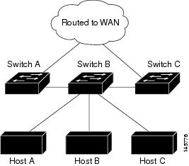
For more information about EIGRP stub routing, see “Configuring EIGRP Stub Routing” section of the Cisco IOS IP Configuration Guide, Volume 2 of 3: Routing Protocols, Release 12.4.
How to Configure EIGRP
To create an EIGRP routing process, you must enable EIGRP and associate networks. EIGRP sends updates to the interfaces in the specified networks. If you do not specify an interface network, it is not advertised in any EIGRP update.
Note |
If you have routers on your network that are configured for IGRP, and you want to change to EIGRP, you must designate transition routers that have both IGRP and EIGRP configured. In these cases, perform Steps 1 through 3 in the next section and also see the “Configuring Split Horizon” section. You must use the same AS number for routes to be automatically redistributed. |
- Default EIGRP Configuration
- Configuring Basic EIGRP Parameters
- Configuring EIGRP Interfaces
- Configuring EIGRP Route Authentication
Default EIGRP Configuration
| Exterior routes are accepted and default information is passed between EIGRP processes when doing redistribution. |
|||
| Only connected routes and interface static routes can be redistributed without a default metric. The metric includes:
|
|||
| For low-speed nonbroadcast multiaccess (NBMA) networks: 60 seconds; all other networks: 5 seconds. |
|||
| For low-speed NBMA networks: 180 seconds; all other networks: 15 seconds. |
|||
| Enabled for IPv4 on switches running the IP services feature set. Allows Layer 3 switches to continue forwarding packets from a neighboring NSF-capable router during hardware or software changes. |
|||
|
|||
Configuring Basic EIGRP Parameters
| Command or Action | Purpose | |
|---|---|---|
| Step 1 |
configure terminal Example: # configure terminal |
|
| Step 2 |
router eigrp autonomous-system Example: (config)# router eigrp 10 |
Enables an EIGRP routing process, and enter router configuration mode. The AS number identifies the routes to other EIGRP routers and is used to tag routing information. |
| Step 3 |
nsf Example: (config)# nsf |
(Optional) Enables EIGRP NSF. Enter this command on the stack master and on all of its peers. |
| Step 4 |
network network-number Example: (config)# network 192.168.0.0 |
Associate networks with an EIGRP routing process. EIGRP sends updates to the interfaces in the specified networks. |
| Step 5 |
eigrp log-neighbor-changes Example: (config)# eigrp log-neighbor-changes |
(Optional) Enables logging of EIGRP neighbor changes to monitor routing system stability. |
| Step 6 |
metric weights
tos k1 k2 k3 k4 k5 Example: (config)# metric weights 0 2 0 2 0 0 |
(Optional) Adjust the EIGRP metric. Although the defaults have been carefully set to provide excellent operation in most networks, you can adjust them. Setting metrics is complex and is not recommended without guidance from an experienced network designer. |
| Step 7 |
offset-list [
access-list number |
name] {
in |
out}
offset [
type number] Example: (config)# offset-list 21 out 10 |
(Optional) Applies an offset list to routing metrics to increase incoming and outgoing metrics to routes learned through EIGRP. You can limit the offset list with an access list or an interface. |
| Step 8 |
auto-summary Example: (config)# auto-summary |
(Optional) Enables automatic summarization of subnet routes into network-level routes. |
| Step 9 |
ip summary-address eigrp
autonomous-system-number address mask Example: (config)# ip summary-address eigrp 1 192.168.0.0 255.255.0.0 |
|
| Step 10 |
end Example: (config)# end |
|
| Step 11 |
show ip protocols Example: # show ip protocols |
|
| Step 12 |
copy running-config startup-config Example: # copy running-config startup-config |
Configuring EIGRP Interfaces
Other optional EIGRP parameters can be configured on an interface basis.
| Command or Action | Purpose | |
|---|---|---|
| Step 1 |
configure terminal Example: # configure terminal |
|
| Step 2 |
interface
interface-id Example: (config)# interface gigabitethernet 1/0/1 |
Enters interface configuration mode, and specifies the Layer 3 interface to configure. |
| Step 3 |
ip bandwidth-percent eigrp
percent Example: (config-if)# ip bandwidth-percent eigrp 60 |
(Optional) Configures the percentage of bandwidth that can be used by EIGRP on an interface. The default is 50 percent. |
| Step 4 |
ip summary-address eigrp
autonomous-system-number address mask Example: (config-if)# ip summary-address eigrp 109 192.161.0.0 255.255.0.0 |
(Optional) Configures a summary aggregate address for a specified interface (not usually necessary if auto-summary is enabled). |
| Step 5 |
ip hello-interval eigrp
autonomous-system-number seconds Example: (config-if)# ip hello-interval eigrp 109 10 |
(Optional) Change the hello time interval for an EIGRP routing process. The range is 1 to 65535 seconds. The default is 60 seconds for low-speed NBMA networks and 5 seconds for all other networks. |
| Step 6 |
ip hold-time eigrp
autonomous-system-number seconds Example: (config-if)# ip hold-time eigrp 109 40 |
(Optional) Change the hold time interval for an EIGRP routing process. The range is 1 to 65535 seconds. The default is 180 seconds for low-speed NBMA networks and 15 seconds for all other networks. Do not adjust the hold time without consulting Cisco technical support. |
| Step 7 |
no ip split-horizon eigrp
autonomous-system-number Example: (config-if)# no ip split-horizon eigrp 109 |
(Optional) Disables split horizon to allow route information to be advertised by a router out any interface from which that information originated. |
| Step 8 |
end Example: (config-if)# end |
|
| Step 9 |
show ip eigrp interface Example: # show ip eigrp interface |
Displays which interfaces EIGRP is active on and information about EIGRP relating to those interfaces. |
| Step 10 |
copy running-config startup-config Example: # copy running-config startup-config |
Configuring EIGRP Route Authentication
EIGRP route authentication provides MD5 authentication of routing updates from the EIGRP routing protocol to prevent the introduction of unauthorized or false routing messages from unapproved sources.
| Command or Action | Purpose | |
|---|---|---|
| Step 1 |
configure terminal Example: # configure terminal |
|
| Step 2 |
interface interface-id Example: (config)# interface gigabitethernet 1/0/1 |
Enters interface configuration mode, and specifies the Layer 3 interface to configure. |
| Step 3 |
ip authentication mode eigrp
autonomous-system
md5 Example: (config-if)# ip authentication mode eigrp 104 md5 |
|
| Step 4 |
ip authentication key-chain eigrp
autonomous-system key-chain Example: (config-if)# ip authentication key-chain eigrp 105 chain1 |
|
| Step 5 |
exit Example: (config-if)# exit |
|
| Step 6 |
key chain
name-of-chain Example: (config)# key chain chain1 |
Identify a key chain and enter key-chain configuration mode. Match the name configured in Step 4. |
| Step 7 |
key
number Example: (config-keychain)# key 1 |
|
| Step 8 |
key-string
text Example: (config-keychain-key)# key-string key1 |
In key-chain key configuration mode, identify the key string. |
| Step 9 |
accept-lifetime
start-time {
infinite |
end-time |
duration
seconds} Example: (config-keychain-key)# accept-lifetime 13:30:00 Jan 25 2011 duration 7200 |
(Optional) Specifies the time period during which the key can be received. The start-time and end-time syntax can be either hh:mm:ss Month date year or hh:mm:ss date Month year. The default is forever with the default start-time and the earliest acceptable date as January 1, 1993. The default end-time and duration is infinite. |
| Step 10 |
send-lifetime
start-time {
infinite |
end-time |
duration
seconds} Example: (config-keychain-key)# send-lifetime 14:00:00 Jan 25 2011 duration 3600 |
(Optional) Specifies the time period during which the key can be sent. The start-time and end-time syntax can be either hh:mm:ss Month date year or hh:mm:ss date Month year. The default is forever with the default start-time and the earliest acceptable date as January 1, 1993. The default end-time and duration is infinite. |
| Step 11 |
end Example: (config-keychain-key)# exit |
|
| Step 12 |
show key chain Example: # show key chain |
|
| Step 13 |
copy running-config startup-config Example: # copy running-config startup-config |
Monitoring and Maintaining EIGRP
You can delete neighbors from the neighbor table. You can also display various EIGRP routing statistics. Table 41-8 lists the privileged EXEC commands for deleting neighbors and displaying statistics. For explanations of fields in the resulting display, see the Cisco IOS IP Command Reference, Volume 2 of 3: Routing Protocols, Release 12.4.
show ip eigrp topology [ autonomous-system-number] | [[ ip-address] mask]] |
|
Displays the number of packets sent and received for all or a specified EIGRP process. |
Information About BGP
The Border Gateway Protocol (BGP) is an exterior gateway protocol used to set up an interdomain routing system that guarantees the loop-free exchange of routing information between autonomous systems. Autonomous systems are made up of routers that operate under the same administration and that run Interior Gateway Protocols (IGPs), such as RIP or OSPF, within their boundaries and that interconnect by using an Exterior Gateway Protocol (EGP). BGP Version 4 is the standard EGP for interdomain routing in the Internet. The protocol is defined in RFCs 1163, 1267, and 1771. You can find detailed information about BGP in Internet Routing Architectures, published by Cisco Press, and in the “Configuring BGP” chapter in the Cisco IP and IP Routing Configuration Guide.
For details about BGP commands and keywords, see the “IP Routing Protocols” part of the Cisco IOS IP Command Reference, Volume 2 of 3: Routing Protocols .
- BGP Network Topology
- Nonstop Forwarding Awareness
- Information About BGP Routing
- Routing Policy Changes
- BGP Decision Attributes
- Route Maps
- BGP Filtering
- Prefix List for BGP Filtering
- BGP Community Filtering
- BGP Neighbors and Peer Groups
- Aggregate Routes
- Routing Domain Confederations
- BGP Route Reflectors
- Route Dampening
- More BGP Information
BGP Network Topology
Routers that belong to the same autonomous system (AS) and that exchange BGP updates run internal BGP (IBGP), and routers that belong to different autonomous systems and that exchange BGP updates run external BGP (EBGP). Most configuration commands are the same for configuring EBGP and IBGP. The difference is that the routing updates are exchanged either between autonomous systems (EBGP) or within an AS (IBGP). Figure 41-5 shows a network that is running both EBGP and IBGP.
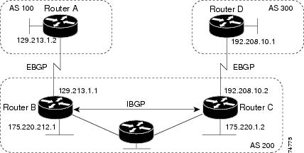
Before exchanging information with an external AS, BGP ensures that networks within the AS can be reached by defining internal BGP peering among routers within the AS and by redistributing BGP routing information to IGPs that run within the AS, such as IGRP and OSPF.
Routers that run a BGP routing process are often referred to as BGP speakers. BGP uses the Transmission Control Protocol (TCP) as its transport protocol (specifically port 179). Two BGP speakers that have a TCP connection to each other for exchanging routing information are known as peers or neighbors. In Figure 41-5, Routers A and B are BGP peers, as are Routers B and C and Routers C and D. The routing information is a series of AS numbers that describe the full path to the destination network. BGP uses this information to construct a loop-free map of autonomous systems.
The network has these characteristics:
- Routers A and B are running EBGP, and Routers B and C are running IBGP. Note that the EBGP peers are directly connected and that the IBGP peers are not. As long as there is an IGP running that allows the two neighbors to reach one another, IBGP peers do not have to be directly connected.
- All BGP speakers within an AS must establish a peer relationship with each other. That is, the BGP speakers within an AS must be fully meshed logically. BGP4 provides two techniques that reduce the requirement for a logical full mesh: confederations and route reflectors.
- AS 200 is a transit AS for AS 100 and AS 300—that is, AS 200 is used to transfer packets between AS 100 and AS 300.
BGP peers initially exchange their full BGP routing tables and then send only incremental updates. BGP peers also exchange keepalive messages (to ensure that the connection is up) and notification messages (in response to errors or special conditions).
In BGP, each route consists of a network number, a list of autonomous systems that information has passed through (the autonomous system path), and a list of other path attributes. The primary function of a BGP system is to exchange network reachability information, including information about the list of AS paths, with other BGP systems. This information can be used to determine AS connectivity, to prune routing loops, and to enforce AS-level policy decisions.
A router or switch running Cisco IOS does not select or use an IBGP route unless it has a route available to the next-hop router and it has received synchronization from an IGP (unless IGP synchronization is disabled). When multiple routes are available, BGP bases its path selection on attribute values. See the “Configuring BGP Decision Attributes” section for information about BGP attributes.
BGP Version 4 supports classless interdomain routing (CIDR) so you can reduce the size of your routing tables by creating aggregate routes, resulting in supernets. CIDR eliminates the concept of network classes within BGP and supports the advertising of IP prefixes.
Nonstop Forwarding Awareness
The BGP NSF Awareness feature is supported for IPv4 in the IP services feature set. To enable this feature with BGP routing, you need to enable Graceful Restart. When the neighboring router is NSF-capable, and this feature is enabled, the Layer 3 switch continues to forward packets from the neighboring router during the interval between the primary Route Processor (RP) in a router failing and the backup RP taking over, or while the primary RP is manually reloaded for a nondisruptive software upgrade.
For more information, see the “BGP Nonstop Forwarding (NSF) Awareness” section of the Cisco IOS IP Routing Protocols Configuration Guide, Release 12.4.
Information About BGP Routing
To enable BGP routing, you establish a BGP routing process and define the local network. Because BGP must completely recognize the relationships with its neighbors, you must also specify a BGP neighbor.
BGP supports two kinds of neighbors: internal and external. Internal neighbors are in the same AS; external neighbors are in different autonomous systems. External neighbors are usually adjacent to each other and share a subnet, but internal neighbors can be anywhere in the same AS.
The switch supports the use of private AS numbers, usually assigned by service providers and given to systems whose routes are not advertised to external neighbors. The private AS numbers are from 64512 to 65535. You can configure external neighbors to remove private AS numbers from the AS path by using the neighbor remove-private-as router configuration command. Then when an update is passed to an external neighbor, if the AS path includes private AS numbers, these numbers are dropped.
If your AS will be passing traffic through it from another AS to a third AS, it is important to be consistent about the routes it advertises. If BGP advertised a route before all routers in the network had learned about the route through the IGP, the AS might receive traffic that some routers could not yet route. To prevent this from happening, BGP must wait until the IGP has propagated information across the AS so that BGP is synchronized with the IGP. Synchronization is enabled by default. If your AS does not pass traffic from one AS to another AS, or if all routers in your autonomous systems are running BGP, you can disable synchronization, which allows your network to carry fewer routes in the IGP and allows BGP to converge more quickly.
Routing Policy Changes
Routing policies for a peer include all the configurations that might affect inbound or outbound routing table updates. When you have defined two routers as BGP neighbors, they form a BGP connection and exchange routing information. If you later change a BGP filter, weight, distance, version, or timer, or make a similar configuration change, you must reset the BGP sessions so that the configuration changes take effect.
There are two types of reset, hard reset and soft reset. Cisco IOS Releases 12.1 and later support a soft reset without any prior configuration. To use a soft reset without preconfiguration, both BGP peers must support the soft route refresh capability, which is advertised in the OPEN message sent when the peers establish a TCP session. A soft reset allows the dynamic exchange of route refresh requests and routing information between BGP routers and the subsequent re-advertisement of the respective outbound routing table.
- When soft reset generates inbound updates from a neighbor, it is called dynamic inbound soft reset.
- When soft reset sends a set of updates to a neighbor, it is called outbound soft reset.
A soft inbound reset causes the new inbound policy to take effect. A soft outbound reset causes the new local outbound policy to take effect without resetting the BGP session. As a new set of updates is sent during outbound policy reset, a new inbound policy can also take effect.
Table 41-10 lists the advantages and disadvantages hard reset and soft reset.
The prefixes in the BGP, IP, and FIB tables provided by the neighbor are lost. Not recommended. |
||
Does not clear the BGP session and cache Does not require storing of routing table updates and has no memory overhead |
Both BGP routers must support the route refresh capability (in Cisco IOS Release 12.1 and later). |
BGP Decision Attributes
When a BGP speaker receives updates from multiple autonomous systems that describe different paths to the same destination, it must choose the single best path for reaching that destination. When chosen, the selected path is entered into the BGP routing table and propagated to its neighbors. The decision is based on the value of attributes that the update contains and other BGP-configurable factors.
When a BGP peer learns two EBGP paths for a prefix from a neighboring AS, it chooses the best path and inserts that path in the IP routing table. If BGP multipath support is enabled and the EBGP paths are learned from the same neighboring autonomous systems, instead of a single best path, multiple paths are installed in the IP routing table. Then, during packet switching, per-packet or per-destination load-balancing is performed among the multiple paths. The maximum-paths router configuration command controls the number of paths allowed.
These factors summarize the order in which BGP evaluates the attributes for choosing the best path:
If the path specifies a next hop that is inaccessible, drop the update. The BGP next-hop attribute, automatically determined by the software, is the IP address of the next hop that is going to be used to reach a destination. For EBGP, this is usually the IP address of the neighbor specified by the neighbor remote-as router configuration command. You can disable next-hop processing by using route maps or the neighbor next-hop-self router configuration command.
- Prefer the path with the largest weight (a Cisco proprietary parameter). The weight attribute is local to the router and not propagated in routing updates. By default, the weight attribute is 32768 for paths that the router originates and zero for other paths. Routes with the largest weight are preferred. You can use access lists, route maps, or the neighbor weight router configuration command to set weights.
- Prefer the route with the highest local preference. Local preference is part of the routing update and exchanged among routers in the same AS. The default value of the local preference attribute is 100. You can set local preference by using the bgp default local-preference router configuration command or by using a route map.
- Prefer the route that was originated by BGP running on the local router.
- Prefer the route with the shortest AS path.
- Prefer the route with the lowest origin type. An interior route or IGP is lower than a route learned by EGP, and an EGP-learned route is lower than one of unknown origin or learned in another way.
- Prefer the route with the lowest multi -exit discriminator (MED) metric attribute if the neighboring AS is the same for all routes considered. You can configure the MED by using route maps or by using the default-metric router configuration command. When an update is sent to an IBGP peer, the MED is included.
- Prefer the external (EBGP) path over the internal (IBGP) path.
- Prefer the route that can be reached through the closest IGP neighbor (the lowest IGP metric). This means that the router will prefer the shortest internal path within the AS to reach the destination (the shortest path to the BGP next-hop).
- If the following conditions are all true, insert the route for this path into the IP routing table: Both the best route and this route are external. Both the best route and this route are from the same neighboring autonomous system. maximum-paths is enabled.
- If multipath is not enabled, prefer the route with the lowest IP address value for the BGP router ID. The router ID is usually the highest IP address on the router or the loopback (virtual) address, but might be implementation-specific.
Route Maps
Within BGP, route maps can be used to control and to modify routing information and to define the conditions by which routes are redistributed between routing domains. See the “Using Route Maps to Redistribute Routing Information” section on page 41-124 for more information about route maps. Each route map has a name that identifies the route map ( map tag) and an optional sequence number.
BGP Filtering
You can filter BGP advertisements by using AS-path filters, such as the as-path access-list global configuration command and the neighbor filter-list router configuration command. You can also use access lists with the neighbor distribute-list router configuration command. Distribute-list filters are applied to network numbers. See the “Controlling Advertising and Processing in Routing Updates” section on page 41-135 for information about the distribute-list command.
You can use route maps on a per-neighbor basis to filter updates and to modify various attributes. A route map can be applied to either inbound or outbound updates. Only the routes that pass the route map are sent or accepted in updates. On both inbound and outbound updates, matching is supported based on AS path, community, and network numbers. Autonomous system path matching requires the match as-path access-list route-map command, community based matching requires the match community-list route-map command, and network-based matching requires the ip access-list global configuration command.
Prefix List for BGP Filtering
You can use prefix lists as an alternative to access lists in many BGP route filtering commands, including the neighbor distribute-list router configuration command. The advantages of using prefix lists include performance improvements in loading and lookup of large lists, incremental update support, easier CLI configuration, and greater flexibility.
Filtering by a prefix list involves matching the prefixes of routes with those listed in the prefix list, as when matching access lists. When there is a match, the route is used. Whether a prefix is permitted or denied is based upon these rules:
- An empty prefix list permits all prefixes.
- An implicit deny is assumed if a given prefix does not match any entries in a prefix list.
- When multiple entries of a prefix list match a given prefix, the sequence number of a prefix list entry identifies the entry with the lowest sequence number.
By default, sequence numbers are generated automatically and incremented in units of five. If you disable the automatic generation of sequence numbers, you must specify the sequence number for each entry. You can specify sequence values in any increment. If you specify increments of one, you cannot insert additional entries into the list; if you choose very large increments, you might run out of values.
BGP Community Filtering
One way that BGP controls the distribution of routing information based on the value of the COMMUNITIES attribute. The attribute is a way to groups destinations into communities and to apply routing decisions based on the communities. This method simplifies configuration of a BGP speaker to control distribution of routing information.
A community is a group of destinations that share some common attribute. Each destination can belong to multiple communities. AS administrators can define to which communities a destination belongs. By default, all destinations belong to the general Internet community. The community is identified by the COMMUNITIES attribute, an optional, transitive, global attribute in the numerical range from 1 to 4294967200. These are some predefined, well-known communities:
- internet—Advertise this route to the Internet community. All routers belong to it.
- no-export—Do not advertise this route to EBGP peers.
- no-advertise—Do not advertise this route to any peer (internal or external).
- local-as—Do not advertise this route to peers outside the local autonomous system.
Based on the community, you can control which routing information to accept, prefer, or distribute to other neighbors. A BGP speaker can set, append, or modify the community of a route when learning, advertising, or redistributing routes. When routes are aggregated, the resulting aggregate has a COMMUNITIES attribute that contains all communities from all the initial routes.
You can use community lists to create groups of communities to use in a match clause of a route map. As with an access list, a series of community lists can be created. Statements are checked until a match is found. As soon as one statement is satisfied, the test is concluded.
To set the COMMUNITIES attribute and match clauses based on communities, see the match community-list and set community route-map configuration commands in the “Using Route Maps to Redistribute Routing Information” section.
BGP Neighbors and Peer Groups
Often many BGP neighbors are configured with the same update policies (that is, the same outbound route maps, distribute lists, filter lists, update source, and so on). Neighbors with the same update policies can be grouped into peer groups to simplify configuration and to make updating more efficient. When you have configured many peers, we recommend this approach.
To configure a BGP peer group, you create the peer group, assign options to the peer group, and add neighbors as peer group members. You configure the peer group by using the neighbor router configuration commands. By default, peer group members inherit all the configuration options of the peer group, including the remote-as (if configured), version, update-source, out-route-map, out-filter-list, out-dist-list, minimum-advertisement-interval, and next-hop-self. All peer group members also inherit changes made to the peer group. Members can also be configured to override the options that do not affect outbound updates.
Aggregate Routes
Classless interdomain routing (CIDR) enables you to create aggregate routes (or supernets) to minimize the size of routing tables. You can configure aggregate routes in BGP either by redistributing an aggregate route into BGP or by creating an aggregate entry in the BGP routing table. An aggregate address is added to the BGP table when there is at least one more specific entry in the BGP table.
Routing Domain Confederations
One way to reduce the IBGP mesh is to divide an autonomous system into multiple subautonomous systems and to group them into a single confederation that appears as a single autonomous system. Each autonomous system is fully meshed within itself and has a few connections to other autonomous systems in the same confederation. Even though the peers in different autonomous systems have EBGP sessions, they exchange routing information as if they were IBGP peers. Specifically, the next hop, MED, and local preference information is preserved. You can then use a single IGP for all of the autonomous systems.
BGP Route Reflectors
BGP requires that all of the IBGP speakers be fully meshed. When a router receives a route from an external neighbor, it must advertise it to all internal neighbors. To prevent a routing information loop, all IBPG speakers must be connected. The internal neighbors do not send routes learned from internal neighbors to other internal neighbors.
With route reflectors, all IBGP speakers need not be fully meshed because another method is used to pass learned routes to neighbors. When you configure an internal BGP peer to be a route reflector, it is responsible for passing IBGP learned routes to a set of IBGP neighbors. The internal peers of the route reflector are divided into two groups: client peers and nonclient peers (all the other routers in the autonomous system). A route reflector reflects routes between these two groups. The route reflector and its client peers form a cluster. The nonclient peers must be fully meshed with each other, but the client peers need not be fully meshed. The clients in the cluster do not communicate with IBGP speakers outside their cluster.
When the route reflector receives an advertised route, it takes one of these actions, depending on the neighbor:
- A route from an external BGP speaker is advertised to all clients and nonclient peers.
- A route from a nonclient peer is advertised to all clients.
- A route from a client is advertised to all clients and nonclient peers. Hence, the clients need not be fully meshed.
Usually a cluster of clients have a single route reflector, and the cluster is identified by the route reflector router ID. To increase redundancy and to avoid a single point of failure, a cluster might have more than one route reflector. In this case, all route reflectors in the cluster must be configured with the same 4-byte cluster ID so that a route reflector can recognize updates from route reflectors in the same cluster. All the route reflectors serving a cluster should be fully meshed and should have identical sets of client and nonclient peers.
Route Dampening
Route flap dampening is a BGP feature designed to minimize the propagation of flapping routes across an internetwork. A route is considered to be flapping when it is repeatedly available, then unavailable, then available, then unavailable, and so on. When route dampening is enabled, a numeric penalty value is assigned to a route when it flaps. When a route’s accumulated penalties reach a configurable limit, BGP suppresses advertisements of the route, even if the route is running. The reuse limit is a configurable value that is compared with the penalty. If the penalty is less than the reuse limit, a suppressed route that is up is advertised again.
Dampening is not applied to routes that are learned by IBGP. This policy prevents the IBGP peers from having a higher penalty for routes external to the AS.
More BGP Information
For detailed descriptions of BGP configuration, see the “Configuring BGP” chapter in the “IP Routing Protocols” part of the Cisco IOS IP Configuration Guide, Release 12.4. For details about specific commands, see the Cisco IOS IP Command Reference, Volume 2 of 3: Routing Protocols, Release 12.4.
How to Configure BGP
Default BGP Configuration
Table 41-9 shows the basic default BGP configuration. For the defaults for all characteristics, see the specific commands in the Cisco IOS IP Command Reference, Volume 2 of 3: Routing Protocols, Release 12.4.
| 100. The range is 0 to 4294967295 with the higher value preferred. |
|
| The IP address of a loopback interface if one is configured or the highest IP address configured for a physical interface on the router. |
|
| Default information originate (protocol or network redistribution) |
|
|
|
| NSF1 Awareness |
Disabled2. If enabled, allows Layer 3 switches to continue forwarding packets from a neighboring NSF-capable router during hardware or software changes. |
Enabling BGP Routing
Note |
To enable BGP, the switch or stack master must be running the IP services feature set. |
| Command or Action | Purpose | |
|---|---|---|
| Step 1 |
configure terminal Example: # configure terminal |
|
| Step 2 |
ip routing Example: (config)# ip routing |
|
| Step 3 |
router bgp
autonomous-system Example: (config)# router bgp 45000 |
Enables a BGP routing process, assign it an AS number, and enter router configuration mode. The AS number can be from 1 to 65535, with 64512 to 65535 designated as private autonomous numbers. |
| Step 4 |
network
network-number [
mask
network-mask] [
route-map
route-map-name] Example: (config)# network 10.108.0.0 |
Configures a network as local to this AS, and enter it in the BGP table. |
| Step 5 |
neighbor {
ip-address |
peer-group-name}
remote-as
number Example: (config)# neighbor 10.108.1.2 remote-as 65200 |
Adds an entry to the BGP neighbor table specifying that the neighbor identified by the IP address belongs to the specified AS. For EBGP, neighbors are usually directly connected, and the IP address is the address of the interface at the other end of the connection. For IBGP, the IP address can be the address of any of the router interfaces. |
| Step 6 |
neighbor {
ip-address |
peer-group-name}
remove-private-as Example: (config)# neighbor 172.16.2.33 remove-private-as |
(Optional) Removes private AS numbers from the AS-path in outbound routing updates. |
| Step 7 |
synchronization Example: (config)# synchronization |
|
| Step 8 |
auto-summary Example: (config)# auto-summary |
(Optional) Enables automatic network summarization. When a subnet is redistributed from an IGP into BGP, only the network route is inserted into the BGP table. |
| Step 9 |
bgp graceful-restart Example: (config)# bgp graceful-start |
(Optional) Enables NSF awareness on switch. By default, NSF awareness is disabled. |
| Step 10 |
end Example: (config)# end |
|
| Step 11 |
show ip bgp network
network-number Example: # show ip bgp network 10.108.0.0 |
|
| Step 12 |
show ip bgp neighbor Example: # show ip bgp neighbor |
Verifies that NSF awareness (Graceful Restart) is enabled on the neighbor. If NSF awareness is enabled on the switch and the neighbor, this message appears: Graceful Restart Capability: advertised and received If NSF awareness is enabled on the switch, but not on the neighbor, this message appears: |
| Step 13 |
copy running-config startup-config Example: # copy running-config startup-config |
Managing Routing Policy Changes
To learn if a BGP peer supports the route refresh capability and to reset the BGP session:
| Command or Action | Purpose | |
|---|---|---|
| Step 1 |
show ip bgp neighbors Example: # show ip bgp neighbors |
Displays whether a neighbor supports the route refresh capability. When supported, this message appears for the router: |
| Step 2 |
clear ip bgp {
* |
address |
peer-group-name} Example: # clear ip bgp * |
|
| Step 3 |
clear ip bgp {
* |
address |
peer-group-name}
soft out Example: # clear ip bgp * soft out |
(Optional) Performs an outbound soft reset to reset the inbound routing table on the specified connection. Use this command if route refresh is supported. |
| Step 4 |
show ip bgp Example: # show ip bgp |
Verifies the reset by checking information about the routing table and about BGP neighbors. |
| Step 5 |
show ip bgp neighbors Example: # show ip bgp neighbors |
Verifies the reset by checking information about the routing table and about BGP neighbors. |
Configuring BGP Decision Attributes
| Command or Action | Purpose | |
|---|---|---|
| Step 1 |
configure terminal Example: # configure terminal |
|
| Step 2 |
router bgp
autonomous-system Example: (config)# router bgp 4500 |
Enables a BGP routing process, assign it an AS number, and enter router configuration mode. |
| Step 3 |
bgp best-path as-path ignore Example: (config-router)# bgp bestpath as-path ignore |
(Optional) Configures the router to ignore AS path length in selecting a route. |
| Step 4 |
neighbor {
ip-address |
peer-group-name}
next-hop-self Example: (config-router)# neighbor 10.108.1.1 next-hop-self |
(Optional) Disables next-hop processing on BGP updates to a neighbor by entering a specific IP address to be used instead of the next-hop address. |
| Step 5 |
neighbor {
ip-address |
peer-group-name}
weight
weight Example: (config-router)# neighbor 172.16.12.1 weight 50 |
(Optional) Assign a weight to a neighbor connection. Acceptable values are from 0 to 65535; the largest weight is the preferred route. Routes learned through another BGP peer have a default weight of 0; routes sourced by the local router have a default weight of 32768. |
| Step 6 |
default-metric
number Example: (config-router)# default-metric 300 |
(Optional) Sets a MED metric to set preferred paths to external neighbors. All routes without a MED will also be set to this value. The range is 1 to 4294967295. The lowest value is the most desirable. |
| Step 7 |
bgp bestpath med missing-as-worst Example: (config-router)# bgp bestpath med missing-as-worst |
(Optional) Configures the switch to consider a missing MED as having a value of infinity, making the path without a MED value the least desirable path. |
| Step 8 |
bgp always-compare med Example: (config-router)# bgp always-compare-med |
(Optional) Configures the switch to compare MEDs for paths from neighbors in different autonomous systems. By default, MED comparison is only done among paths in the same AS. |
| Step 9 |
bgp bestpath med confed Example: (config-router)# bgp bestpath med confed |
(Optional) Configures the switch to consider the MED in choosing a path from among those advertised by different subautonomous systems within a confederation. |
| Step 10 |
bgp deterministic med Example: (config-router)# bgp deterministic med |
(Optional) Configures the switch to consider the MED variable when choosing among routes advertised by different peers in the same AS. |
| Step 11 |
bgp default local-preference
value Example: (config-router)# bgp default local-preference 200 |
(Optional) Change the default local preference value. The range is 0 to 4294967295; the default value is 100. The highest local preference value is preferred. |
| Step 12 |
maximum-paths
number Example: (config-router)# maximum-paths 8 |
(Optional) Configures the number of paths to be added to the IP routing table. The default is to only enter the best path in the routing table. The range is from 1 to 16. Having multiple paths allows load-balancing among the paths. (Although the switch software allows a maximum of 32 equal-cost routes, the switch hardware will never use more than 16 paths per route.) |
| Step 13 |
end Example: (config-router)# end |
|
| Step 14 |
show ip bgp Example: # show ip bgp |
Verifies the reset by checking information about the routing table and about BGP neighbors. |
| Step 15 |
show ip bgp neighbors Example: # show ip bgp neighbors |
Verifies the reset by checking information about the routing table and about BGP neighbors. |
| Step 16 |
copy running-config startup-config Example: # copy running-config startup-config |
Configuring BGP Filtering with Route Maps
| Command or Action | Purpose | |
|---|---|---|
| Step 1 |
configure terminal Example: # configure terminal |
|
| Step 2 |
route-map
map-tag [
permit |
deny] [
sequence-number] Example: (config)# route-map set-peer-address permit 10 |
Creates a route map, and enter route-map configuration mode. |
| Step 3 |
set ip next-hop
ip-address [
...ip-address] [
peer-address] Example: (config)# set ip next-hop 10.1.1.3 |
|
| Step 4 |
end Example: (config)# end |
|
| Step 5 |
show route-map [
map-name] Example: # show route-map |
Displays all route maps configured or only the one specified to verify configuration. |
| Step 6 |
copy running-config startup-config Example: # copy running-config startup-config |
Configuring BGP Filtering by Neighbor
| Command or Action | Purpose | |||
|---|---|---|---|---|
| Step 1 |
configure terminal Example: # configure terminal |
|||
| Step 2 |
router bgp
autonomous-system Example: (config)# router bgp 109 |
Enables a BGP routing process, assign it an AS number, and enter router configuration mode. |
||
| Step 3 |
neighbor {
ip-address |
peer-group name}
distribute-list {
access-list-number |
name} {
in |
out} Example: (config-router)# neighbor 172.16.4.1 distribute-list 39 in |
(Optional) Filters BGP routing updates to or from neighbors as specified in an access list.
|
||
| Step 4 |
neighbor {
ip-address |
peer-group name}
route-map
map-tag {
in |
out} Example: (config-router)# neighbor 172.16.70.24 route-map internal-map in |
(Optional) Applies a route map to filter an incoming or outgoing route. |
||
| Step 5 |
end Example: (config-router)# end |
|||
| Step 6 |
show ip bgp neighbors Example: # show ip bgp neighbors |
|||
| Step 7 |
copy running-config startup-config Example: # copy running-config startup-config |
Configuring BGP Filtering by Access Lists and Neighbors
Another method of filtering is to specify an access list filter on both incoming and outbound updates, based on the BGP autonomous system paths. Each filter is an access list based on regular expressions. (See the “Regular Expressions” appendix in the Cisco IOS Dial Technologies Command Reference, Release 12.4 for more information on forming regular expressions.) To use this method, define an autonomous system path access list, and apply it to updates to and from particular neighbors.
| Command or Action | Purpose | |
|---|---|---|
| Step 1 |
configure terminal Example: # configure terminal |
|
| Step 2 |
ip as-path access-list
access-list-number {
permit |
deny}
as-regular-expressions Example: (config)# ip as-path access-list 1 deny _65535_ |
|
| Step 3 |
router bgp
autonomous-system Example: (config)# router bgp 110 |
|
| Step 4 |
neighbor {
ip-address |
peer-group name}
filter-list {
access-list-number |
name} {
in |
out |
weight
weight} Example: (config-router)# neighbor 172.16.1.1 filter-list 1 out |
|
| Step 5 |
end Example: (config-router)# end |
|
| Step 6 |
show ip bgp neighbors [
paths
regular-expression] Example: # show ip bgp neighbors |
|
| Step 7 |
copy running-config startup-config Example: # copy running-config startup-config |
Configuring Prefix Lists for BGP Filtering
You do not need to specify a sequence number when removing a configuration entry. Show commands include the sequence numbers in their output.
Before using a prefix list in a command, you must set up the prefix list.
| Command or Action | Purpose | |
|---|---|---|
| Step 1 |
configure terminal Example: # configure terminal |
|
| Step 2 |
ip prefix-list
list-name [
seq
seq-value]
deny |
permit
network/len [
ge
ge-value] [
le
le-value] Example: (config)# ip prefix-list BLUE permit 172.16.1.0/24 |
Creates a prefix list with an optional sequence number to deny or permit access for matching conditions. You must enter at least one permit or deny clause. |
| Step 3 |
ip prefix-list
list-name
seq
seq-value
deny |
permit
network/len [
ge
ge-value] [
le
le-value] Example: (config)# ip prefix-list BLUE seq 10 permit 172.24.1.0/24 |
(Optional) Adds an entry to a prefix list, and assign a sequence number to the entry. |
| Step 4 |
end Example: (config)# end |
|
| Step 5 |
show ip prefix list [
detail |
summary]
name [
network/len] [
seq
seq-num] [
longer] [
first-match] Example: # show ip prefix list summary test |
Verifies the configuration by displaying information about a prefix list or prefix list entries. |
| Step 6 |
copy running-config startup-config Example: # copy running-config startup-config |
Configuring BGP Community Filtering
By default, no COMMUNITIES attribute is sent to a neighbor. You can specify that the COMMUNITIES attribute be sent to the neighbor at an IP address by using the neighbor send-community router configuration command.
2.
ip community-list
community-list-number {
permit |
deny}
community-number
3.
router bgp
autonomous-system
4.
neighbor {
ip-address |
peer-group name}
send-community
5.
set comm-list
list-num
delete
DETAILED STEPS
| Command or Action | Purpose | |
|---|---|---|
| Step 1 |
configure terminal Example: # configure terminal |
|
| Step 2 |
ip community-list
community-list-number {
permit |
deny}
community-number Example: (config)# ip community-list 1 permit 50000:10 |
|
| Step 3 |
router bgp
autonomous-system Example: (config)# router bgp 108 |
|
| Step 4 |
neighbor {
ip-address |
peer-group name}
send-community Example: (config-router)# neighbor 172.16.70.23 send-community |
Specifies that the COMMUNITIES attribute be sent to the neighbor at this IP address. |
| Step 5 |
set comm-list
list-num
delete Example: (config-router)# set comm-list 500 delete |
(Optional) Removes communities from the community attribute of an inbound or outbound update that match a standard or extended community list specified by a route map. |
| Step 6 |
exit Example: (config-router)# end |
|
| Step 7 |
ip bgp-community new-format Example: (config)# ip bgp-community new format |
(Optional) Displays and parses BGP communities in the format AA:NN. A BGP community is displayed in a two-part format 2 bytes long. The Cisco default community format is in the format NNAA. In the most recent RFC for BGP, a community takes the form AA:NN, where the first part is the AS number and the second part is a 2-byte number. |
| Step 8 |
end Example: (config)# end |
|
| Step 9 |
show ip bgp community Example: # show ip bgp community |
|
| Step 10 |
copy running-config startup-config Example: # copy running-config startup-config |
Configuring BGP Neighbors and Peer Groups
To assign configuration options to an individual neighbor, specify any of these router configuration commands by using the neighbor IP address. To assign the options to a peer group, specify any of the commands by using the peer group name. You can disable a BGP peer or peer group without removing all the configuration information by using the neighbor shutdown router configuration command.
| Command or Action | Purpose | |
|---|---|---|
| Step 1 |
configure terminal |
|
| Step 2 |
router bgp
autonomous-system |
|
| Step 3 |
neighbor
peer-group-name
peer-group |
|
| Step 4 |
neighbor
ip-address
peer-group
peer-group-name |
|
| Step 5 |
neighbor {
ip-address |
peer-group-name}
remote-as
number |
Specifies a BGP neighbor. If a peer group is not configured with a remote-as number, use this command to create peer groups containing EBGP neighbors. The range is 1 to 65535. |
| Step 6 |
neighbor {
ip-address |
peer-group-name}
description
text |
|
| Step 7 |
neighbor {
ip-address |
peer-group-name}
default-originate [
route-map
map-name] |
(Optional) Allows a BGP speaker (the local router) to send the default route 0.0.0.0 to a neighbor for use as a default route. |
| Step 8 |
neighbor {
ip-address |
peer-group-name}
send-community |
(Optional) Specifies that the COMMUNITIES attribute be sent to the neighbor at this IP address. |
| Step 9 |
neighbor {
ip-address |
peer-group-name}
update-source
interface |
(Optional) Allows internal BGP sessions to use any operational interface for TCP connections. |
| Step 10 |
neighbor {
ip-address |
peer-group-name}
ebgp-multihop |
(Optional) Allows BGP sessions, even when the neighbor is not on a directly connected segment. The multihop session is not established if the only route to the multihop peer’s address is the default route (0.0.0.0). |
| Step 11 |
neighbor {
ip-address |
peer-group-name}
local-as
number |
(Optional) Specifies an AS number to use as the local AS. The range is 1 to 65535. |
| Step 12 |
neighbor {
ip-address |
peer-group-name}
advertisement-interval
seconds |
(Optional) Sets the minimum interval between sending BGP routing updates. |
| Step 13 |
neighbor {
ip-address |
peer-group-name}
maximum-prefix
maximum [
threshold] |
(Optional) Controls how many prefixes can be received from a neighbor. The range is 1 to 4294967295. The threshold (optional) is the percentage of maximum at which a warning message is generated. The default is 75 percent. |
| Step 14 |
neighbor {
ip-address |
peer-group-name}
next-hop-self |
(Optional) Disables next-hop processing on the BGP updates to a neighbor. |
| Step 15 | neighbor { ip-address | peer-group-name} password string | (Optional) Sets MD5 authentication on a TCP connection to a BGP peer. The same password must be configured on both BGP peers, or the connection between them is not made. |
| Step 16 |
neighbor {
ip-address |
peer-group-name}
route-map
map-name {
in |
out} |
(Optional) Applies a route map to incoming or outgoing routes. |
| Step 17 |
neighbor {
ip-address |
peer-group-name}
send-community |
(Optional) Specifies that the COMMUNITIES attribute be sent to the neighbor at this IP address. |
| Step 18 |
neighbor {
ip-address |
peer-group-name}
timers
keepalive holdtime |
(Optional) Sets timers for the neighbor or peer group.
|
| Step 19 |
neighbor {
ip-address |
peer-group-name}
weight
weight |
(Optional) Specifies a weight for all routes from a neighbor. |
| Step 20 |
neighbor {
ip-address |
peer-group-name}
distribute-list {
access-list-number |
name} {
in |
out} |
(Optional) Filter BGP routing updates to or from neighbors, as specified in an access list. |
| Step 21 |
neighbor {
ip-address |
peer-group-name}
filter-list
access-list-number {
in |
out |
weight
weight} |
|
| Step 22 |
neighbor {
ip-address |
peer-group-name}
version
value |
(Optional) Specifies the BGP version to use when communicating with a neighbor. |
| Step 23 |
neighbor {
ip-address |
peer-group-name}
soft-reconfiguration inbound |
(Optional) Configures the software to start storing received updates. |
| Step 24 |
end |
|
| Step 25 |
show ip bgp neighbors |
|
| Step 26 |
copy running-config startup-config |
Configuring Aggregate Addresses in a Routing Table
| Command or Action | Purpose | |
|---|---|---|
| Step 1 |
configure terminal Example: # configure terminal |
|
| Step 2 |
router bgp
autonomous-system Example: (config)# router bgp 106 |
|
| Step 3 |
aggregate-address
address mask Example: (config-router)# aggregate-address 10.0.0.0 255.0.0.0 |
Creates an aggregate entry in the BGP routing table. The aggregate route is advertised as coming from the AS, and the atomic aggregate attribute is set to indicate that information might be missing. |
| Step 4 |
aggregate-address
address mask
as-set Example: (config-router)# aggregate-address 10.0.0.0 255.0.0.0 as-set |
(Optional) Generates AS set path information. This command creates an aggregate entry following the same rules as the previous command, but the advertised path will be an AS_SET consisting of all elements contained in all paths. Do not use this keyword when aggregating many paths because this route must be continually withdrawn and updated. |
| Step 5 |
aggregate-address
address-mask
summary-only Example: (config-router)# aggregate-address 10.0.0.0 255.0.0.0 summary-only |
|
| Step 6 |
aggregate-address
address mask
suppress-map
map-name Example: (config-router)# aggregate-address 10.0.0.0 255.0.0.0 suppress-map map1 |
|
| Step 7 |
aggregate-address
address mask
advertise-map
map-name Example: (config-router)# aggregate-address 10.0.0.0 255.0.0.0 advertise-map map2 |
(Optional) Generates an aggregate based on conditions specified by the route map. |
| Step 8 |
aggregate-address
address mask
attribute-map
map-name Example: (config-router)# aggregate-address 10.0.0.0 255.0.0.0 attribute-map map3 |
(Optional) Generates an aggregate with attributes specified in the route map. |
| Step 9 |
end Example: (config-router)# end |
|
| Step 10 |
show ip bgp neighbors [
advertised-routes] Example: # show ip bgp neighbors |
|
| Step 11 |
copy running-config startup-config Example: # copy running-config startup-config |
Configuring Routing Domain Confederations
You must specify a confederation identifier that acts as the autonomous system number for the group of autonomous systems.
| Command or Action | Purpose | |
|---|---|---|
| Step 1 |
configure terminal Example: # configure terminal |
|
| Step 2 |
router bgp
autonomous-system Example: (config)# router bgp 100 |
|
| Step 3 |
bgp confederation identifier
autonomous-system Example: (config)# bgp confederation identifier 50007 |
|
| Step 4 |
bgp confederation peers
autonomous-system [
autonomous-system ...] Example: (config)# bgp confederation peers 51000 51001 51002 |
Specifies the autonomous systems that belong to the confederation and that will be treated as special EBGP peers. |
| Step 5 |
end Example: (config)# end |
|
| Step 6 |
show ip bgp neighbor Example: # show ip bgp neighbor |
|
| Step 7 |
show ip bgp network Example: # show ip bgp network |
|
| Step 8 |
copy running-config startup-config Example: # copy running-config startup-config |
Configuring BGP Route Reflectors
| Command or Action | Purpose | |
|---|---|---|
| Step 1 |
configure terminal Example: # configure terminal |
|
| Step 2 |
router bgp
autonomous-system Example: (config)# router bgp 101 |
|
| Step 3 |
neighbor {
ip-address |
peer-group-name}
route-reflector-client Example: (config-router)# neighbor 172.16.70.24 route-reflector-client |
Configures the local router as a BGP route reflector and the specified neighbor as a client. |
| Step 4 |
bgp cluster-id
cluster-id Example: (config-router)# bgp cluster-id 10.0.1.2 |
(Optional) Configures the cluster ID if the cluster has more than one route reflector. |
| Step 5 |
no bgp client-to-client reflection Example: (config-router)# no bgp client-to-client reflection |
(Optional) Disables client-to-client route reflection. By default, the routes from a route reflector client are reflected to other clients. However, if the clients are fully meshed, the route reflector does not need to reflect routes to clients. |
| Step 6 |
end Example: (config-router)# end |
|
| Step 7 |
show ip bgp Example: # show ip bgp |
Verifies the configuration. Displays the originator ID and the cluster-list attributes. |
| Step 8 |
copy running-config startup-config Example: # copy running-config startup-config |
Configuring Route Dampening
| Command or Action | Purpose | |
|---|---|---|
| Step 1 |
configure terminal Example: # configure terminal |
|
| Step 2 |
router bgp
autonomous-system Example: (config)# router bgp 100 |
|
| Step 3 |
bgp dampening Example: (config-router)# bgp dampening |
|
| Step 4 |
bgp dampening
half-life reuse suppress max-suppress [
route-map
map] Example: (config-router)# bgp dampening 30 1500 10000 120 |
(Optional) Changes the default values of route dampening factors. |
| Step 5 |
end Example: (config-router)# end |
|
| Step 6 |
show ip bgp flap-statistics [{
regexp
regexp} | {
filter-list
list} | {
address mask [
longer-prefix]}] Example: # show ip bgp flap-statistics |
(Optional) Monitors the flaps of all paths that are flapping. The statistics are deleted when the route is not suppressed and is stable. |
| Step 7 |
show ip bgp dampened-paths Example: # show pi bgp dampened-paths |
(Optional) Displays the dampened routes, including the time remaining before they are suppressed. |
| Step 8 |
clear ip bgp flap-statistics [{
regexp
regexp} | {
filter-list
list} | {
address mask [
longer-prefix]} Example: # clear ip bgp flap-statistics |
(Optional) Clears BGP flap statistics to make it less likely that a route will be dampened. |
| Step 9 |
clear ip bgp dampening Example: # clear ip bgp dampening |
(Optional) Clears route dampening information, and unsuppress the suppressed routes. |
| Step 10 |
copy running-config startup-config Example: # copy running-config startup-config |
Monitoring and Maintaining BGP
You can remove all contents of a particular cache, table, or database. This might be necessary when the contents of the particular structure have become or are suspected to be invalid.
You can display specific statistics, such as the contents of BGP routing tables, caches, and databases. You can use the information to get resource utilization and solve network problems. You can also display information about node reachability and discover the routing path your device’s packets are taking through the network.
Table 41-8 lists the privileged EXEC commands for clearing and displaying BGP. For explanations of the display fields, see the Cisco IOS IP Command Reference, Volume 2 of 3: Routing Protocols, Release 12.4.
| Displays peer groups and peers not in peer groups to which the prefix has been advertised. Also display prefix attributes such as the next hop and the local prefix. |
|
| Displays all BGP routes that contain subnet and supernet network masks. |
|
| show ip bgp community-list community-list-number [ exact-match] |
|
| Displays routes that are matched by the specified AS path access list. |
|
| Displays the routes with inconsistent originating autonomous systems. |
|
| Displays the routes that have an AS path that matches the specified regular expression entered on the command line. |
|
| Displays detailed information on the BGP and TCP connections to individual neighbors. |
|
| show ip bgp neighbors [ address] [ advertised-routes | dampened-routes | flap-statistics | paths regular-expression | received-routes | routes] |
|
The bgp log-neighbor changes command is enabled by default. It allows to log messages that are generated when a BGP neighbor resets, comes up, or goes down.
Configuration Examples for BGP
Example: Configuring BGP on Routers
(config)# router bgp 100
(config-router)# neighbor 129.213.1.1 remote-as 200
(config)# router bgp 200
(config-router)# neighbor 129.213.1.2 remote-as 100
(config-router)# neighbor 175.220.1.2 remote-as 200
(config)# router bgp 200
(config-router)# neighbor 175.220.212.1 remote-as 200
(config-router)# neighbor 192.208.10.1 remote-as 300
(config)# router bgp 300
(config-router)# neighbor 192.208.10.2 remote-as 200
To verify that BGP peers are running, use the show ip bgp neighbors privileged EXEC command. This is the output of this command on Router A:
# show ip bgp neighbors

BGP neighbor is 129.213.1.1, remote AS 200, external link
 BGP version 4, remote router ID 175.220.212.1
 BGP state = established, table version = 3, up for 0:10:59
 Last read 0:00:29, hold time is 180, keepalive interval is 60 seconds
 Minimum time between advertisement runs is 30 seconds
 Received 2828 messages, 0 notifications, 0 in queue
 Sent 2826 messages, 0 notifications, 0 in queue
 Connections established 11; dropped 10
Anything other than state = established means that the peers are not running. The remote router ID is the highest IP address on that router (or the highest loopback interface). Each time the table is updated with new information, the table version number increments. A table version number that continually increments means that a route is flapping, causing continual routing updates.
For exterior protocols, a reference to an IP network from the network router configuration command controls only which networks are advertised. This is in contrast to Interior Gateway Protocols (IGPs), such as EIGRP, which also use the network command to specify where to send updates.
For detailed descriptions of BGP configuration, see the “IP Routing Protocols” part of the Cisco IOS IP Configuration Guide, Release 12.4. For details about specific commands, see the Cisco IOS IP Command Reference, Volume 2 of 3: Routing Protocols, Release 12.4.
Information About ISO CLNS Routing
Connectionless Routing
The International Organization for Standardization (ISO) Connectionless Network Service (CLNS) protocol is a standard for the network layer of the Open System Interconnection (OSI) model. Addresses in the ISO network architecture are referred to as network service access point (NSAP) addresses and network entity titles (NETs). Each node in an OSI network has one or more NETs. In addition, each node has many NSAP addresses.
When you enable connectionless routing on the switch by using the clns routing global configuration command, the switch makes only forwarding decisions, with no routing-related functionality. For dynamic routing, you must also enable a routing protocol. The switch supports the Intermediate System-to-Intermediate System (IS-IS) dynamic routing protocol that is based on the OSI routing protocol for ISO CLNS networks.
When dynamically routing, you use IS-IS. This routing protocol supports the concept of areas. Within an area, all routers know how to reach all the system IDs. Between areas, routers know how to reach the proper area. IS-IS supports two levels of routing: station routing (within an area) and area routing (between areas).
The key difference between the ISO IGRP and IS-IS NSAP addressing schemes is in the definition of area addresses. Both use the system ID for Level 1 routing (routing within an area). However, they differ in the way addresses are specified for area routing. An ISO IGRP NSAP address includes three separate fields for routing: the domain, area, and system ID. An IS-IS address includes two fields: a single continuous area field (comprising the domain and area fields) and the system ID.
Note |
For more detailed information about ISO CLNS, see the Cisco IOS Apollo Domain, Banyan VINES, DECnet, ISO CLNS and XNS Configuration Guide, Release 12.4. For complete syntax and usage information for the commands used in this chapter, see the Cisco IOS Apollo Domain, Banyan VINES, DECnet, ISO CLNS and XNS Command Reference, Release 12.4, use the IOS command reference master index, or search online. |
IS-IS Dynamic Routing
IS-IS is an ISO dynamic routing protocol (described in ISO 105890). Unlike other routing protocols, enabling IS-IS requires that you create an IS-IS routing process and assign it to a specific interface, rather than to a network. You can specify more than one IS-IS routing process per Layer 3 switch or router by using the multiarea IS-IS configuration syntax. You then configure the parameters for each instance of the IS-IS routing process.
Small IS-IS networks are built as a single area that includes all the routers in the network. As the network grows larger, it is usually reorganized into a backbone area made up of the connected set of all Level 2 routers from all areas, which is in turn connected to local areas. Within a local area, routers know how to reach all system IDs. Between areas, routers know how to reach the backbone, and the backbone routers know how to reach other areas.
Routers establish Level 1 adjacencies to perform routing within a local area (station routing). Routers establish Level 2 adjacencies to perform routing between Level 1 areas (area routing).
A single Cisco router can participate in routing in up to 29 areas and can perform Level 2 routing in the backbone. In general, each routing process corresponds to an area. By default, the first instance of the routing process configured performs both Level 1and Level 2 routing. You can configure additional router instances, which are automatically treated as Level 1 areas. You must configure the parameters for each instance of the IS-IS routing process individually.
For IS-IS multiarea routing, you can configure only one process to perform Level 2 routing, although you can define up to 29 Level 1 areas for each Cisco unit. If Level 2 routing is configured on any process, all additional processes are automatically configured as Level 1. You can configure this process to perform Level 1 routing at the same time. If Level 2 routing is not desired for a router instance, remove the Level 2 capability using the is-type global configuration command. Use the is-type command also to configure a different router instance as a Level 2 router.
Note |
For more detailed information about IS-IS, see the “IP Routing Protocols” chapter of the Cisco IOS IP Configuration Guide, Release 12.4. For complete syntax and usage information for the commands used in this section, see the Cisco IOS IP Command Reference, Release 12.4. |
Nonstop Forwarding Awareness
The integrated IS-IS NSF Awareness feature is supported for IPv4G. The feature allows customer premises equipment (CPE) routers that are NSF-aware to help NSF-capable routers perform nonstop forwarding of packets. The local router is not necessarily performing NSF, but its awareness of NSF allows the integrity and accuracy of the routing database and link-state database on the neighboring NSF-capable router to be maintained during the switchover process.
This feature is automatically enabled and requires no configuration. For more information on this feature, see the Integrated IS-IS Nonstop Forwarding (NSF) Awareness Feature Guide.
IS-IS Global Parameters
These are some optional IS-IS global parameters that you can configure:
- You can force a default route into an IS-IS routing domain by configuring a default route controlled by a route map. You can also specify other filtering options configurable under a route map.
- You can configure the router to ignore IS-IS LSPs that are received with internal checksum errors or to purge corrupted LSPs, which causes the initiator of the LSP to regenerate it.
- You can assign passwords to areas and domains.
- You can create aggregate addresses that are represented in the routing table by a summary address (route-summarization). Routes learned from other routing protocols can also be summarized. The metric used to advertise the summary is the smallest metric of all the specific routes.
- You can set an overload bit.
- You can configure the LSP refresh interval and the maximum time that an LSP can remain in the router database without a refresh
- You can set the throttling timers for LSP generation, shortest path first computation, and partial route computation.
- You can configure the switch to generate a log message when an IS-IS adjacency changes state (up or down).
- If a link in the network has a maximum transmission unit (MTU) size of less than 1500 bytes, you can lower the LSP MTU so that routing will still occur.
- The partition avoidance router configuration command prevents an area from becoming partitioned when full connectivity is lost among a Level1-2 border router, adjacent Level 1 routers, and end hosts.
IS-IS Interface Parameters
You can optionally configure certain interface-specific IS-IS parameters, independently from other attached routers. However, if you change some values from the defaults, such as multipliers and time intervals, it makes sense to also change them on multiple routers and interfaces. Most of the interface parameters can be configured for level 1, level 2, or both.
These are some interface level parameters you can configure:
- The default metric on the interface, which is used as a value for the IS-IS metric and assigned when there is no quality of service (QoS) routing performed.
- The hello interval (length of time between hello packets sent on the interface) or the default hello packet multiplier used on the interface to determine the hold time sent in IS-IS hello packets. The hold time determines how long a neighbor waits for another hello packet before declaring the neighbor down. This determines how quickly a failed link or neighbor is detected so that routes can be recalculated. Change the hello-multiplier in circumstances where hello packets are lost frequently and IS-IS adjacencies are failing unnecessarily. You can raise the hello multiplier and lower the hello interval correspondingly to make the hello protocol more reliable without increasing the time required to detect a link failure.
-
Other time intervals:
- Complete sequence number PDU (CSNP) interval. CSNPs are sent by the designated router to maintain database synchronization
- Retransmission interval. This is the time between retransmission of IS-IS LSPs for point-to-point links.
- IS-IS LSP retransmission throttle interval. This is the maximum rate (number of milliseconds between packets) at which IS-IS LSPs are re-sent on point-to-point links This interval is different from the retransmission interval, which is the time between successive retransmissions of the same LSP
- Designated router election priority, which allows you to reduce the number of adjacencies required on a multiaccess network, which in turn reduces the amount of routing protocol traffic and the size of the topology database.
- The interface circuit type, which is the type of adjacency desired for neighbors on the specified interface
- Password authentication for the interface
How to Configure ISO CLNS Routing
Default IS-IS Configuration
| Conventional IS-IS: the router acts as both a Level 1 (station) and a Level 2 (area) router. Multiarea IS-IS: the first instance of the IS-IS routing process is a Level 1-2 router. Remaining instances are Level 1 routers. |
|
| Maximum interval between two consecutive occurrences: 5 seconds. Initial LSP generation delay: 50 ms. Hold time between the first and second LSP generation: 5000 ms. |
|
| 1200 seconds (20 minutes) before t.he LSP packet is deleted. |
|
| Enabled. Allows Layer 3 switches to continue forwarding packets from a neighboring NSF-capable router during hardware or software changes. |
|
| Maximum PRC wait interval: 5 seconds. Initial PRC calculation delay after a topology change: 2000 ms. Hold time between the first and second PRC calculation: 5000 ms. |
|
| No area or domain password is defined, and authentication is disabled. |
|
| Disabled. When enabled, if no arguments are entered, the overload bit is set immediately and remains set until you enter the no set-overload-bit command. |
|
| Maximum interval between consecutive SFPs: 10 seconds. Initial SFP calculation after a topology change: 5500 ms. Holdtime between the first and second SFP calculation: 5500 ms. |
|
Enabling IS-IS Routing
To enable IS-IS, you specify a name and NET for each routing process. You then enable IS-IS routing on the interface and specify the area for each instance of the routing process.
| Command or Action | Purpose | |
|---|---|---|
| Step 1 |
configure terminal Example: # configure terminal |
|
| Step 2 |
clns routing Example: (config)# clns routing |
|
| Step 3 |
router isis [
area tag] Example: (config)# router isis tag1 |
Enables the IS-IS routing for the specified routing process and enter IS-IS routing configuration mode. (Optional) Use the area tag argument to identify the area to which the IS-IS router is assigned. You must enter a value if you are configuring multiple IS-IS areas. The first IS-IS instance configured is Level 1-2 by default. Later instances are automatically Level 1. You can change the level of routing by using the is-type global configuration command. |
| Step 4 |
net network-entity-title Example: (config-router)# net 47.0004.004d.0001.0001.0c11.1111.00 |
Configures the NETs for the routing process. If you are configuring multiarea IS-IS, specify a NET for each routing process. You can specify a name for a NET and for an address. |
| Step 5 |
is-type {
level-1 |
level-1-2 |
level-2-only} Example: (config-router)# is-type level-2-only |
(Optional) Configures the router to act as a Level 1 (station) router, a Level 2 (area) router for multi-area routing, or both (the default): |
| Step 6 |
exit Example: (config-router)# end |
|
| Step 7 |
interface
interface-id Example: (config)# interface gigabitethernet 1/0/1 |
Specifies an interface to route IS-IS, and enter interface configuration mode. If the interface is not already configured as a Layer 3 interface, enter the no switchport command to put it into Layer 3 mode. |
| Step 8 |
ip router isis [
area tag] Example: (config-if)# ip router isis tag1 |
Configures an IS-IS routing process for ISO CLNS on the interface and attach an area designator to the routing process. |
| Step 9 |
clns router isis [
area tag] Example: (config-if)# clns router isis tag1 |
|
| Step 10 |
ip address
ip-address-mask Example: (config-if)# ip address 10.0.0.5 255.255.255.0 |
Define the IP address for the interface. An IP address is required on all interfaces in an area enabled for IS-IS if any one interface is configured for IS-IS routing. |
| Step 11 |
end Example: (config-if)# end |
|
| Step 12 |
show isis [
area tag]
database detail Example: # show isis database detail |
|
| Step 13 |
copy running-config startup-config Example: # copy running-config startup-config |
Configuring IS-IS Global Parameters
| Command or Action | Purpose | |||
|---|---|---|---|---|
| Step 1 |
configure terminal Example: # configure terminal |
|||
| Step 2 |
clns routing Example: (config)# clns routing |
|||
| Step 3 |
router isis Example: (config)# router isis |
Specifies the IS-IS routing protocol and enter router configuration mode. |
||
| Step 4 |
default-information originate [
route-map
map-name] Example: (config-router)# default-information originate route-map map1 |
(Optional) Forces a default route into the IS-IS routing domain.If you enter route-map map-name, the routing process generates the default route if the route map is satisfied. |
||
| Step 5 |
ignore-lsp-errors Example: (config-router)# ignore-lsp-errors |
(Optional) Configures the router to ignore LSPs with internal checksum errors, instead of purging the LSPs. This command is enabled by default (corrupted LSPs are dropped). To purge the corrupted LSPs, enter the no ignore-lsp-errors router configuration command. |
||
| Step 6 |
area-password
password Example: (config-router)# area-password 1password |
(Optional Configures the area authentication password, which is inserted in Level 1 (station router level) LSPs. |
||
| Step 7 |
domain-password
password Example: (config-router)# domain-password 2password |
(Optional) Configures the routing domain authentication password, which is inserted in Level 2 (area router level) LSPs. |
||
| Step 8 |
summary-address
address mask [
level-1 |
level-1-2 |
level-2] Example: (config-router)# summary-address 10.1.0.0 255.255.0.0 level-2 |
(Optional) Creates a summary of addresses for a given level. |
||
| Step 9 |
set-overload-bit [
on-startup {
seconds |
wait-for-bgp}] Example: (config-router)# set-overload-bit on-startup wait-for-bgp |
(Optional) Sets an overload bit (a hippity bit) to allow other routers to ignore the router in their shortest path first (SPF) calculations if the router is having problems.
|
||
| Step 10 |
lsp-refresh-interval
seconds Example: (config-router)# lsp-refresh-interval 1080 |
(Optional) Sets an LSP refresh interval in seconds. The range is from 1 to 65535 seconds. The default is to send LSP refreshes every 900 seconds (15 minutes). |
||
| Step 11 |
max-lsp-lifetime
seconds Example: (config-router)# max-lsp-lifetime 1000 |
(Optional) Sets the maximum time that LSP packets remain in the router database without being refreshed. The range is from 1 to 65535 seconds. The default is 1200 seconds (20 minutes). After the specified time interval, the LSP packet is deleted. |
||
| Step 12 |
lsp-gen-interval [
level-1 |
level-2]
lsp-max-wait [
lsp-initial-wait lsp-second-wait] Example: (config-router)# lsp-gen-interval level-2 2 50 100 |
(Optional) Sets the IS-IS LSP generation throttling timers:
|
||
| Step 13 |
spf-interval [
level-1 |
level-2]
spf-max-wait [
spf-initial-wait spf-second-wait] Example: (config-router)# spf-interval level-2 5 10 20 |
(Optional) Sets IS-IS shortest path first (SPF) throttling timers.
|
||
| Step 14 |
prc-interval
prc-max-wait [
prc-initial-wait prc-second-wait] Example: (config-router)# prc-interval 5 10 20 |
(Optional) Sets IS-IS partial route computation (PRC) throttling timers.
|
||
| Step 15 |
log-adjacency-changes [
all] Example: (config-router)# log-adjacency-changes all |
(Optional) Sets the router to log IS-IS adjacency state changes. Enter all to include all changes generated by events that are not related to the Intermediate System-to-Intermediate System Hellos, including End System-to-Intermediate System PDUs and link state packets (LSPs). |
||
| Step 16 |
lsp-mtu
size Example: (config-router)# lsp mtu 1560 |
(Optional) Specifies the maximum LSP packet size in bytes. The range is 128 to 4352; the default is 1497 bytes.
|
||
| Step 17 |
partition avoidance Example: (config-router)# partition avoidance |
(Optional) Causes an IS-IS Level 1-2 border router to stop advertising the Level 1 area prefix into the Level 2 backbone when full connectivity is lost among the border router, all adjacent level 1 routers, and end hosts. |
||
| Step 18 |
end Example: (config-router)# end |
|||
| Step 19 |
show clns Example: # show clns |
|||
| Step 20 |
copy running-config startup-config Example: # copy running-config startup-config |
Configuring IS-IS Interface Parameters
| Command or Action | Purpose | |
|---|---|---|
| Step 1 |
configure terminal Example: # configure terminal |
|
| Step 2 |
interface
interface-id Example: (config)# interface gigabitethernet 1/0/1 |
Specifies the interface to be configured and enter interface configuration mode. If the interface is not already configured as a Layer 3 interface, enter the no switchport command to put it into Layer 3 mode. |
| Step 3 |
isis metric
default-metric [
level-1 |
level-2] Example: (config-if)# isis metric 15 |
(Optional) Configures the metric (or cost) for the specified interface. The range is from 0 to 63. The default is 10. If no level is entered, the default is to apply to both Level 1 and Level 2 routers. |
| Step 4 |
isis hello-interval {
seconds |
minimal} [
level-1 |
level-2] Example: (config-if)# isis hello-interval minimal |
(Optional) Specifies the length of time between hello packets sent by the switch. By default, a value three times the hello interval seconds is advertised as the holdtime in the hello packets sent. With smaller hello intervals, topological changes are detected faster, but there is more routing traffic. |
| Step 5 |
isis hello-multiplier
multiplier [
level-1 |
level-2] Example: (config-if)# isis hello-multiplier 5 |
(Optional) Specifies the number of IS-IS hello packets a neighbor must miss before the router should declare the adjacency as down. The range is from 3 to 1000. The default is 3. Using a smaller hello-multiplier causes fast convergence, but can result in more routing instability. |
| Step 6 |
isis csnp-interval
seconds [
level-1 |
level-2] Example: (config-if)# isis csnp-interval 15 |
(Optional) Configures the IS-IS complete sequence number PDU (CSNP) interval for the interface. The range is from 0 to 65535. The default is 10 seconds. |
| Step 7 |
isis retransmit-interval
seconds Example: (config-if)# isis retransmit-interval 7 |
(Optional) Configures the number of seconds between retransmission of IS-IS LSPs for point-to-point links. The value you specify should be an integer greater than the expected round-trip delay between any two routers on the network. The range is from 0 to 65535. The default is 5 seconds. |
| Step 8 |
isis retransmit-throttle-interval
milliseconds Example: (config-if)# isis retransmit-throttle-interval 4000 |
(Optional) Configures the IS-IS LSP retransmission throttle interval, which is the maximum rate (number of milliseconds between packets) at which IS-IS LSPs will be re-sent on point-to-point links. The range is from 0 to 65535. The default is determined by the isis lsp-interval command. |
| Step 9 |
isis priority
value [
level-1 |
level-2] Example: (config-if)# isis priority 50 |
(Optional) Configures the priority to use for designated router election. The range is from 0 to 127. The default is 64. |
| Step 10 |
isis circuit-type {
level-1 |
level-1-2 |
level-2-only} Example: (config-if)# isis circuit-type level-1-2 |
(Optional) Configures the type of adjacency desired for neighbors on the specified interface (specify the interface circuit type).
|
| Step 11 |
isis password
password [
level-1 |
level-2] Example: (config-if)# isis password secret |
(Optional) Configures the authentication password for an interface. By default, authentication is disabled. Specifying Level 1 or Level 2 enables the password only for Level 1 or Level 2 routing, respectively. If you do not specify a level, the default is Level 1 and Level 2. |
| Step 12 |
end Example: (config-if)# end |
|
| Step 13 |
show clns interface
interface-id Example: # show clns interface gigabitethernet 1/0/1 |
|
| Step 14 |
copy running-config startup-config Example: # copy running-config startup-config |
Monitoring and Maintaining ISO IGRP and IS-IS
You can remove all contents of a CLNS cache or remove information for a particular neighbor or route. You can display specific CLNS or IS-IS statistics, such as the contents of routing tables, caches, and databases. You can also display information about specific interfaces, filters, or neighbors.
Table 41-13 lists the privileged EXEC commands for clearing and displaying ISO CLNS and IS-IS routing. For explanations of the display fields, see the Cisco IOS Apollo Domain, Banyan VINES, DECnet, ISO CLNS and XNS Command Reference, Release 12.4, use the Cisco IOS command reference master index, or search online.
Removes end system (ES) neighbor information from the adjacency database. |
|
Removes intermediate system (IS) neighbor information from the adjacency database. |
|
Removes CLNS neighbor information from the adjacency database. |
|
Displays ES neighbor entries, including the associated areas. |
|
Displays the CLNS-specific or ES-IS information about each interface. |
|
List the protocol-specific information for each IS-IS or ISO IGRP routing process in this router. |
|
Displays all the destinations to which this router knows how to route CLNS packets. |
|
Displays information about the CLNS packets this router has seen. |
|
Displays a history of the shortest path first (SPF) calculations for IS-IS. |
|
Displays all route maps configured or only the one specified. |
|
Discover the paths taken to a specified destination by packets in the network. |
|
Displays the routing table in which the specified CLNS destination is found. |
Configuration Examples for ISO CLNS Routing
Example: Configuring IS-IS Routing
This example shows how to configure three routers to run conventional IS-IS as an IP routing protocol. In conventional IS-IS, all routers act as Level 1 and Level 2 routers (by default).
(config)# clns routing
(config)# router isis
(config-router)# net 49.0001.0000.0000.000a.00
(config-router)# exit
(config)# interface gigabitethernet1/0/1
(config-if)# ip router isis
(config-if)# clns router isis
(config)# interface gigabitethernet1/0/2
(config-if)# ip router isis
(config-if)# clns router isis
(config-router)# exit
(config)# clns routing
(config)# router isis
(config-router)# net 49.0001.0000.0000.000b.00
(config-router)# exit
(config)# interface gigabitethernet1/0/1
(config-if)# ip router isis
(config-if)# clns router isis
(config)# interface gigabitethernet1/0/2
(config-if)# ip router isis
(config-if)# clns router isis
(config-router)# exit
(config)# clns routing
(config)# router isis
(config-router)# net 49.0001.0000.0000.000c.00
(config-router)# exit
(config)# interface gigabitethernet1/0/1
(config-if)# ip router isis
(config-if)# clns router isis
(config)# interface gigabitethernet1/0/2
(config-if)# ip router isis
(config-if)# clns router isis
(config-router)# exit
Information About Multi-VRF CE
Virtual Private Networks (VPNs) provide a secure way for customers to share bandwidth over an ISP backbone network. A VPN is a collection of sites sharing a common routing table. A customer site is connected to the service-provider network by one or more interfaces, and the service provider associates each interface with a VPN routing table, called a VPN routing/forwarding (VRF) table.
The switch supports multiple VPN routing/forwarding (multi-VRF) instances in customer edge (CE) devices (multi-VRF CE) when the it is running the IP services or advanced IP services feature set. Multi-VRF CE allows a service provider to support two or more VPNs with overlapping IP addresses.
Note |
The switch does not use Multiprotocol Label Switching (MPLS) to support VPNs. For information about MPLS VRF, see the Cisco IOS Switching Services Configuration Guide, Release 12.4. |
Understanding Multi-VRF CE
Multi-VRF CE is a feature that allows a service provider to support two or more VPNs, where IP addresses can be overlapped among the VPNs. Multi-VRF CE uses input interfaces to distinguish routes for different VPNs and forms virtual packet-forwarding tables by associating one or more Layer 3 interfaces with each VRF. Interfaces in a VRF can be either physical, such as Ethernet ports, or logical, such as VLAN SVIs, but an interface cannot belong to more than one VRF at any time.
Note |
Multi-VRF CE interfaces must be Layer 3 interfaces. |
Multi-VRF CE includes these devices:
- Customer edge (CE) devices provide customers access to the service-provider network over a data link to one or more provider edge routers. The CE device advertises the site’s local routes to the router and learns the remote VPN routes from it. A switch can be a CE.
- Provider edge (PE) routers exchange routing information with CE devices by using static routing or a routing protocol such as BGP, RIPv2, OSPF, or EIGRP. The PE is only required to maintain VPN routes for those VPNs to which it is directly attached, eliminating the need for the PE to maintain all of the service-provider VPN routes. Each PE router maintains a VRF for each of its directly connected sites. Multiple interfaces on a PE router can be associated with a single VRF if all of these sites participate in the same VPN. Each VPN is mapped to a specified VRF. After learning local VPN routes from CEs, a PE router exchanges VPN routing information with other PE routers by using internal BGP (IBPG).
- Provider routers or core routers are any routers in the service provider network that do not attach to CE devices.
With multi-VRF CE, multiple customers can share one CE, and only one physical link is used between the CE and the PE. The shared CE maintains separate VRF tables for each customer and switches or routes packets for each customer based on its own routing table. Multi-VRF CE extends limited PE functionality to a CE device, giving it the ability to maintain separate VRF tables to extend the privacy and security of a VPN to the branch office.
Network Topology
Figure 41-6 shows a configuration using switches as multiple virtual CEs. This scenario is suited for customers who have low bandwidth requirements for their VPN service, for example, small companies. In this case, multi-VRF CE support is required in the switches. Because multi-VRF CE is a Layer 3 feature, each interface in a VRF must be a Layer 3 interface.
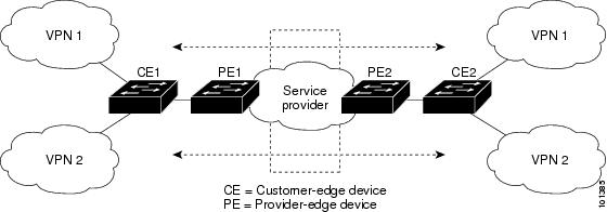
When the CE switch receives a command to add a Layer 3 interface to a VRF, it sets up the appropriate mapping between the VLAN ID and the policy label (PL) in multi-VRF-CE-related data structures and adds the VLAN ID and PL to the VLAN database.
When multi-VRF CE is configured, the Layer 3 forwarding table is conceptually partitioned into two sections:
- The multi-VRF CE routing section contains the routes from different VPNs.
- The global routing section contains routes to non-VPN networks, such as the Internet.
VLAN IDs from different VRFs are mapped into different policy labels, which are used to distinguish the VRFs during processing. For each new VPN route learned, the Layer 3 setup function retrieves the policy label by using the VLAN ID of the ingress port and inserts the policy label and new route to the multi-VRF CE routing section. If the packet is received from a routed port, the port internal VLAN ID number is used; if the packet is received from an SVI, the VLAN number is used.
Packet-Forwarding Process
This is the packet-forwarding process in a multi-VRF-CE-enabled network:
- When the switch receives a packet from a VPN, the switch looks up the routing table based on the input policy label number. When a route is found, the switch forwards the packet to the PE.
- When the ingress PE receives a packet from the CE, it performs a VRF lookup. When a route is found, the router adds a corresponding MPLS label to the packet and sends it to the MPLS network.
- When an egress PE receives a packet from the network, it strips the label and uses the label to identify the correct VPN routing table. Then it performs the normal route lookup. When a route is found, it forwards the packet to the correct adjacency.
- When a CE receives a packet from an egress PE, it uses the input policy label to look up the correct VPN routing table. If a route is found, it forwards the packet within the VPN.
Network Components
To configure VRF, you create a VRF table and specify the Layer 3 interface associated with the VRF. Then configure the routing protocols in the VPN and between the CE and the PE. BGP is the preferred routing protocol used to distribute VPN routing information across the provider’s backbone. The multi-VRF CE network has three major components:
- VPN route target communities—lists of all other members of a VPN community. You need to configure VPN route targets for each VPN community member.
- Multiprotocol BGP peering of VPN community PE routers—propagates VRF reachability information to all members of a VPN community. You need to configure BGP peering in all PE routers within a VPN community.
- VPN forwarding—transports all traffic between all VPN community members across a VPN service-provider network.
VRF-Aware Services
IP services can be configured on global interfaces, and these services run within the global routing instance. IP services are enhanced to run on multiple routing instances; they are VRF-aware. Any configured VRF in the system can be specified for a VRF-aware service.
VRF-Aware services are implemented in platform-independent modules. VRF means multiple routing instances in Cisco IOS. Each platform has its own limit on the number of VRFs it supports.
How to Configure Multi-VRF CE
Default Multi-VRF CE Configuration
Fast Ethernet switches: 8000 Gigabit Ethernet switches: 12000. |
|
Multi-VRF CE Configuration Guidelines
Note |
To use multi-VRF CE, you must have the IP services or advanced IP services feature set enabled on your switch.
|
Configuring VRFs
For complete syntax and usage information for the commands, see the switch command reference for this release and the Cisco IOS Switching Services Command Reference, Release 12.4.
| Command or Action | Purpose | |
|---|---|---|
| Step 1 |
configure terminal Example: # configure terminal |
|
| Step 2 |
ip routing Example: (config)# ip routing |
|
| Step 3 |
ip vrf
vrf-name Example: (config)# ip vrf vpn1 |
|
| Step 4 |
rd
route-distinguisher Example: (config-vrf)# rd 100:2 |
Creates a VRF table by specifying a route distinguisher. Enter either an AS number and an arbitrary number (xxx:y) or an IP address and arbitrary number (A.B.C.D:y) |
| Step 5 |
route-target {
export |
import |
both}
route-target-ext-community Example: (config-vrf)# route-target both 100:2 |
Creates a list of import, export, or import and export route target communities for the specified VRF. Enter either an AS system number and an arbitrary number (xxx:y) or an IP address and an arbitrary number (A.B.C.D:y). The route-target-ext-community should be the same as the route-distinguisher entered in Step 4. |
| Step 6 |
import map
route-map Example: (config-vrf)# import map importmap1 |
|
| Step 7 |
interface
interface-id Example: (config-vrf)# interface gigabitethernet 1/0/1 |
Specifies the Layer 3 interface to be associated with the VRF, and enter interface configuration mode. The interface can be a routed port or SVI. |
| Step 8 |
ip vrf forwarding
vrf-name Example: (config-if)# ip vrf forwarding vpn1 |
|
| Step 9 |
end Example: (config-if)# end |
|
| Step 10 |
show ip vrf [
brief |
detail |
interfaces] [
vrf-name] Example: # show ip vrf interfaces vpn1 |
Verifies the configuration. Displays information about the configured VRFs. |
| Step 11 |
copy running-config startup-config Example: # copy running-config startup-config |
Configuring VRF-Aware Services
- Configuring VRF-Aware Services for ARP
- Configuring VRF-Aware Services for Ping
- Configuring VRF-Aware Services for SNMP
- Configuring VRF-Aware Servcies for uRPF
- Configuring VRF-Aware RADIUS
- Configuring VRF-Aware Services for Syslog
- Configuring VRF-Aware Services for Traceroute
- Configuring VRF-Aware Services for FTP and TFTP
Configuring VRF-Aware Services for ARP
For complete syntax and usage information for the commands, see the switch command reference for this release and the Cisco IOS Switching Services Command Reference, Release 12.4.
| Command or Action | Purpose | |
|---|---|---|
| Step 1 | Example: # show ip arp vrf vpn1 |
Configuring VRF-Aware Services for Ping
For complete syntax and usage information for the commands, see the switch command reference for this release and the Cisco IOS Switching Services Command Reference, Release 12.4.
| Command or Action | Purpose | |
|---|---|---|
| Step 1 |
ping vrf vrf-name ip-host Example: # ping vrf vpn1 ip-host |
Configuring VRF-Aware Services for SNMP
For complete syntax and usage information for the commands, refer to the switch command reference for this release and the Cisco IOS Switching Services Command Reference, Release 12.4.
| Command or Action | Purpose | |
|---|---|---|
| Step 1 |
configure terminal Example: # configure terminal |
|
| Step 2 |
snmp-server trap authentication vrf Example: (config)# snmp-server trap authentication vrf |
|
| Step 3 |
snmp-server engineID remote
host
vrf
vpn-instance engine-id string Example: (config)# snmp-server engineID remote 172.16.20.3 vrf vpn1 80000009030000B064EFE100 |
|
| Step 4 |
snmp-server host
host
vrf
vpn-instance
traps
community Example: (config)# snmp-server host 172.16.20.3 vrf vpn1 traps comaccess |
Specifies the recipient of an SNMP trap operation and specifies the VRF table to be used for sending SNMP traps. |
| Step 5 |
snmp-server host
host
vrf
vpn-instance
informs
community Example: (config)# snmp-server host 172.16.20.3 vrf vpn1 informs comaccess |
Specifies the recipient of an SNMP inform operation and specifies the VRF table to be used for sending SNMP informs. |
| Step 6 |
snmp-server user
user group
remote
host
vrf
vpn-instance security model Example: (config)# snmp-server user abcd remote 172.16.20.3 vrf vpn1 priv v2c 3des secure3des |
Adds a user to an SNMP group for a remote host on a VRF for SNMP access. |
| Step 7 |
end Example: (config)# end |
Configuring VRF-Aware Servcies for uRPF
uRPF can be configured on an interface assigned to a VRF, and source lookup is done in the VRF table.
For complete syntax and usage information for the commands, refer to the switch command reference for this release and the Cisco IOS Switching Services Command Reference, Release 12.4.
| Command or Action | Purpose | |
|---|---|---|
| Step 1 |
configure terminal Example: # configure terminal |
|
| Step 2 | interface interface-id (config)# interface gigabitethernet 1/0/1 | Enters interface configuration mode, and specifies the Layer 3 interface to configure. |
| Step 3 |
no switchport Example: (config-if)# no switchport |
Removes the interface from Layer 2 configuration mode if it is a physical interface. |
| Step 4 |
ip vrf forwarding
vrf-name Example: (config-if)# ip vrf forwarding vpn2 |
|
| Step 5 |
ip address
ip-address Example: (config-if)# ip address 10.1.5.1 |
|
| Step 6 |
ip verify unicast reverse-path Example: (config-if)# ip verify unicast reverse-path |
|
| Step 7 |
end Example: (config-if)# end |
Configuring VRF-Aware RADIUS
To configure VRF-Aware RADIUS, you must first enable AAA on a RADIUS server. The switch supports the ip vrf forwarding vrf-name server-group configuration and the ip radius source-interface global configuration commands, as described in the Per VRF AAA Feature Guide.
Configuring VRF-Aware Services for Syslog
For complete syntax and usage information for the commands, refer to the switch command reference for this release and the Cisco IOS Switching Services Command Reference, Release 12.4.
| Command or Action | Purpose | |
|---|---|---|
| Step 1 |
configure terminal Example: # configure terminal |
|
| Step 2 |
logging on Example: (config)# logging on |
Enables or temporarily disables logging of storage router event message. |
| Step 3 |
logging host
ip-address
vrf
vrf-name Example: (config)# logging host 10.10.1.0 vrf vpn1 |
Specifies the host address of the syslog server where logging messages are to be sent. |
| Step 4 |
logging buffered
logging buffered size
debugging Example: (config)# logging buffered critical 6000 debugging |
|
| Step 5 |
logging trap debugging Example: (config)# logging trap debugging |
|
| Step 6 |
logging facility
facility Example: (config)# logging facility user |
|
| Step 7 |
end Example: (config)# end |
Configuring VRF-Aware Services for Traceroute
For complete syntax and usage information for the commands, refer to the switch command reference for this release and the Cisco IOS Switching Services Command Reference, Release 12.4.
| Command or Action | Purpose | |
|---|---|---|
| Step 1 |
traceroute vrf
vrf-name ipaddress Example: (config)# traceroute vrf vpn2 10.10.1.1 |
Specifies the name of a VPN VRF in which to find the destination address. |
Configuring VRF-Aware Services for FTP and TFTP
So that FTP and TFTP are VRF-aware, you must configure some FTP/TFTP CLIs. For example, if you want to use a VRF table that is attached to an interface, say E1/0, you need to configure the ip tftp source-interface E1/0 or the ip ftp source-interface E1/0 command to inform TFTP or FTP server to use a specific routing table. In this example, the VRF table is used to look up the destination IP address. These changes are backward-compatible and do not affect existing behavior. That is, you can use the source-interface CLI to send packets out a particular interface even if no VRF is configured on that interface.
| Command or Action | Purpose | |
|---|---|---|
| Step 1 |
configure terminal Example: # configure terminal |
|
| Step 2 |
ip ftp source-interface
interface-type interface-number Example: (config)# ip ftp source-interface gigabitethernet 1/0/2 |
|
| Step 3 |
end Example: (config)#end |
|
| Step 4 |
configure terminal Example: # configure terminal |
|
| Step 5 |
ip tftp source-interface
interface-type interface-number Example: (config)# ip tftp source-interface gigabitethernet 1/0/2 |
|
| Step 6 |
end Example: (config)#end |
Configuring Multicast VRFs
For complete syntax and usage information for the commands, see the switch command reference for this release and the Cisco IOS Switching Services Command Reference, Release 12.4.
For more information about configuring a multicast within a Multi-VRF CE, see the Cisco IOS IP Multicast Configuration Guide, Release 12.4.
| Command or Action | Purpose | |
|---|---|---|
| Step 1 |
configure terminal Example: # configure terminal |
|
| Step 2 |
ip routing Example: (config)# ip routing |
|
| Step 3 |
ip vrf
vrf-name Example: (config)# ip vrf vpn1 |
|
| Step 4 |
rd
route-distinguisher Example: (config-vrf)# rd 100:2 |
Creates a VRF table by specifying a route distinguisher. Enter either an AS number and an arbitrary number (xxx:y) or an IP address and an arbitrary number (A.B.C.D:y) |
| Step 5 |
route-target {
export |
import |
both}
route-target-ext-community Example: (config-vrf)# route-target import 100:2 |
Creates a list of import, export, or import and export route target communities for the specified VRF. Enter either an AS system number and an arbitrary number (xxx:y) or an IP address and an arbitrary number (A.B.C.D:y). The route-target-ext-community should be the same as the route-distinguisher entered in Step 4. |
| Step 6 |
import map
route-map Example: (config-vrf)# import map importmap1 |
|
| Step 7 |
ip multicast-routing vrf
vrf-name
distributed Example: (config-vrf)# ip multicast-routing vrf vpn1 distributed |
|
| Step 8 |
interface
interface-id Example: (config-vrf)# interface gigabitethernet 1/0/2 |
Specifies the Layer 3 interface to be associated with the VRF, and enter interface configuration mode. The interface can be a routed port or an SVI. |
| Step 9 |
ip vrf forwarding
vrf-name Example: (config-if)# ip vrf forwarding vpn1 |
|
| Step 10 |
ip address
ip-address
mask Example: (config-if)# ip address 10.1.5.1 255.255.255.0 |
|
| Step 11 |
ip pim sparse-dense mode Example: (config-if)# ip pim sparse-dense mode |
|
| Step 12 |
end Example: (config-if)# end |
|
| Step 13 |
show ip vrf [
brief |
detail |
interfaces] [
vrf-name] Example: # show ip vrf detail vpn1 |
Verifies the configuration. Displays information about the configured VRFs. |
| Step 14 |
copy running-config startup-config Example: # copy running-config startup-config |
Configuring a VPN Routing Session
Routing within the VPN can be configured with any supported routing protocol (RIP, OSPF, EIGRP, or BGP) or with static routing. The configuration shown here is for OSPF, but the process is the same for other protocols.
Note |
To configure an EIGRP routing process to run within a VRF instance, you must configure an autonomous-system number by entering the autonomous-system autonomous-system-number address-family configuration mode command. |
| Command or Action | Purpose | |
|---|---|---|
| Step 1 |
configure terminal Example: # configure terminal |
|
| Step 2 |
router ospf
process-id
vrf
vrf-name Example: (config)# router ospf 1 vrf vpn1 |
Enables OSPF routing, specifies a VPN forwarding table, and enter router configuration mode. |
| Step 3 |
log-adjacency-changes Example: (config-router)# log-adjacency-changes |
(Optional) Logs changes in the adjacency state. This is the default state. |
| Step 4 |
redistribute bgp
autonomous-system-number
subnets Example: (config-router)# redistribute bgp 10 subnets |
Sets the switch to redistribute information from the BGP network to the OSPF network. |
| Step 5 |
network
network-number
area
area-id Example: (config-router)# network 1 area 2 |
Defines a network address and mask on which OSPF runs and the area ID for that network address. |
| Step 6 |
end Example: (config-router)# end |
|
| Step 7 |
show ip ospf
process-id Example: # show ip ospf 1 |
|
| Step 8 |
copy running-config startup-config Example: # copy running-config startup-config |
Configuring BGP PE to CE Routing Sessions
| Command or Action | Purpose | |
|---|---|---|
| Step 1 |
configure terminal Example: # configure terminal |
|
| Step 2 |
router bgp
autonomous-system-number Example: (config)# router bgp 2 |
Configures the BGP routing process with the AS number passed to other BGP routers, and enter router configuration mode. |
| Step 3 |
network
network-number
mask
network-mask Example: (config-router)# network 5 mask 255.255.255.0 |
|
| Step 4 |
redistribute ospf
process-id
match internal Example: (config-router)# redistribute ospf 1 match internal |
|
| Step 5 |
network
network-number
area
area-id Example: (config-router)# network 5 area 2 |
Defines a network address and mask on which OSPF runs and the area ID for that network address. |
| Step 6 |
address-family ipv4 vrf
vrf-name Example: (config-router)# address-family ipv4 vrf vpn1 |
Defines BGP parameters for PE to CE routing sessions, and enter VRF address-family mode. |
| Step 7 |
neighbor
address
remote-as
as-number Example: (config-router)# neighbor 10.1.1.2 remote-as 2 |
|
| Step 8 |
neighbor
address
activate Example: (config-router)# neighbor 10.2.1.1 activate |
|
| Step 9 |
end Example: (config-router)# end |
|
| Step 10 |
show ip bgp [
ipv4] [
neighbors] Example: # show ip bgp ipv4 neighbors |
|
| Step 11 |
copy running-config startup-config Example: # copy running-config startup-config |
Monitoring Multi-VRF CE
Displays routing protocol information associated with a VRF. |
|
show ip route vrf vrf-name [ connected] [ protocol [ as-number]] [ list] [ mobile] [ odr] [ profile] [ static] [ summary] [ supernets-only] |
Displays IP routing table information associated with a VRF. |
For more information about the information in the displays, see the Cisco IOS Switching Services Command Reference, Release 12.4.
Configuration Examples for Multi-VRF CE
Multi-VRF CE Configuration Example
Figure 41-7 is a simplified example of the physical connections in a network similar to that in Figure 41-6. OSPF is the protocol used in VPN1, VPN2, and the global network. BGP is used in the CE to PE connections. The examples following the illustration show how to configure a switch as CE Switch A, and the VRF configuration for customer switches D and F. Commands for configuring CE Switch C and the other customer switches are not included but would be similar. The example also includes commands for configuring traffic to Switch A for a Catalyst 6000 or Catalyst 6500 switch acting as a PE router.
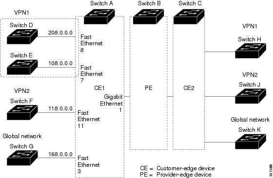
On Switch A, enable routing and configure VRF.
# configure terminal
Enter configuration commands, one per line.  End with CNTL/Z.
(config)# ip routing
(config)# ip vrf v11
(config-vrf)# rd 800:1
(config-vrf)# route-target export 800:1
(config-vrf)# route-target import 800:1
(config-vrf)# exit
(config)# ip vrf v12
(config-vrf)# rd 800:2
(config-vrf)# route-target export 800:2
(config-vrf)# route-target import 800:2
(config-vrf)# exit
Configure the loopback and physical interfaces on Switch A. Gigabit Ethernet port 1 is a trunk connection to the PE. Gigabit Ethernet ports 8 and 11 connect to VPNs:
(config)# interface loopback1
(config-if)# ip vrf forwarding v11
(config-if)# ip address 8.8.1.8 255.255.255.0
(config-if)# exit

(config)# interface loopback2
(config-if)# ip vrf forwarding v12
(config-if)# ip address 8.8.2.8 255.255.255.0
(config-if)# exit

(config)# interface gigabitethernet1/0/5
(config-if)# switchport trunk encapsulation dot1q
(config-if)# switchport mode trunk
(config-if)# no ip address
(config-if)# exit
(config)# interface gigabitethernet1/0/8
(config-if)# switchport access vlan 208
(config-if)# no ip address
(config-if)# exit
(config)# interface gigabitethernet1/0/11
(config-if)# switchport trunk encapsulation dot1q
(config-if)# switchport mode trunk
(config-if)# no ip address
(config-if)# exit
Configure the VLANs used on Switch A. VLAN 10 is used by VRF 11 between the CE and the PE. VLAN 20 is used by VRF 12 between the CE and the PE. VLANs 118 and 208 are used for the VPNs that include Switch F and Switch D, respectively:
(config)# interface vlan10
(config-if)# ip vrf forwarding v11
(config-if)# ip address 38.0.0.8 255.255.255.0
(config-if)# exit
(config)# interface vlan20
(config-if)# ip vrf forwarding v12
(config-if)# ip address 83.0.0.8 255.255.255.0
(config-if)# exit
(config)# interface vlan118
(config-if)# ip vrf forwarding v12
(config-if)# ip address 118.0.0.8 255.255.255.0
(config-if)# exit
(config)# interface vlan208
(config-if)# ip vrf forwarding v11
(config-if)# ip address 208.0.0.8 255.255.255.0
(config-if)# exit
Configure OSPF routing in VPN1 and VPN2.
(config)# router ospf 1 vrf vl1
(config-router)# redistribute bgp 800 subnets
(config-router)# network 208.0.0.0 0.0.0.255 area 0
(config-router)# exit
(config)# router ospf 2 vrf vl2
(config-router)# redistribute bgp 800 subnets
(config-router)# network 118.0.0.0 0.0.0.255 area 0
(config-router)# exit
Configure BGP for CE to PE routing.
(config)# router bgp 800
(config-router)# address-family ipv4 vrf vl2
(config-router-af)# redistribute ospf 2 match internal
(config-router-af)# neighbor 83.0.0.3 remote-as 100
(config-router-af)# neighbor 83.0.0.3 activate
(config-router-af)# network 8.8.2.0 mask 255.255.255.0
(config-router-af)# exit
(config-router)# address-family ipv4 vrf vl1
(config-router-af)# redistribute ospf 1 match internal
(config-router-af)# neighbor 38.0.0.3 remote-as 100
(config-router-af)# neighbor 38.0.0.3 activate
(config-router-af)# network 8.8.1.0 mask 255.255.255.0
(config-router-af)# end
Switch D belongs to VPN 1. Configure the connection to Switch A by using these commands.
# configure terminal
Enter configuration commands, one per line.  End with CNTL/Z.
(config)# ip routing
(config)# interface gigabitethernet1/0/2
(config-if)# no switchport
(config-if)# ip address 208.0.0.20 255.255.255.0
(config-if)# exit

(config)# router ospf 101
(config-router)# network 208.0.0.0 0.0.0.255 area 0
(config-router)# end
Switch F belongs to VPN 2. Configure the connection to Switch A by using these commands.
# configure terminal
Enter configuration commands, one per line.  End with CNTL/Z.
(config)# ip routing
(config)# interface gigabitethernet1/0/1
(config-if)# switchport trunk encapsulation dot1q
(config-if)# switchport mode trunk
(config-if)# no ip address
(config-if)# exit

(config)# interface vlan118
(config-if)# ip address 118.0.0.11 255.255.255.0
(config-if)# exit

(config)# router ospf 101
(config-router)# network 118.0.0.0 0.0.0.255 area 0
(config-router)# end
When used on switch B (the PE router), these commands configure only the connections to the CE device, Switch A.
Router# configure terminal
Enter configuration commands, one per line.  End with CNTL/Z.
Router(config)# ip vrf v1
Router(config-vrf)# rd 100:1
Router(config-vrf)# route-target export 100:1
Router(config-vrf)# route-target import 100:1
Router(config-vrf)# exit

Router(config)# ip vrf v2
Router(config-vrf)# rd 100:2
Router(config-vrf)# route-target export 100:2
Router(config-vrf)# route-target import 100:2
Router(config-vrf)# exit
Router(config)# ip cef
Router(config)# interface Loopback1
Router(config-if)# ip vrf forwarding v1
Router(config-if)# ip address 3.3.1.3 255.255.255.0
Router(config-if)# exit

Router(config)# interface Loopback2
Router(config-if)# ip vrf forwarding v2
Router(config-if)# ip address 3.3.2.3 255.255.255.0
Router(config-if)# exit

Router(config)# interface gigabitethernet1/1/0.10
Router(config-if)# encapsulation dot1q 10
Router(config-if)# ip vrf forwarding v1
Router(config-if)# ip address 38.0.0.3 255.255.255.0
Router(config-if)# exit

Router(config)# interface gigabitethernet1/1/0.20
Router(config-if)# encapsulation dot1q 20
Router(config-if)# ip vrf forwarding v2
Router(config-if)# ip address 83.0.0.3 255.255.255.0
Router(config-if)# exit

Router(config)# router bgp 100
Router(config-router)# address-family ipv4 vrf v2
Router(config-router-af)# neighbor 83.0.0.8 remote-as 800
Router(config-router-af)# neighbor 83.0.0.8 activate
Router(config-router-af)# network 3.3.2.0 mask 255.255.255.0
Router(config-router-af)# exit
Router(config-router)# address-family ipv4 vrf vl
Router(config-router-af)# neighbor 38.0.0.8 remote-as 800
Router(config-router-af)# neighbor 38.0.0.8 activate
Router(config-router-af)# network 3.3.1.0 mask 255.255.255.0
Router(config-router-af)# end
Configuring Unicast Reverse Path Forwarding
The unicast reverse path forwarding (unicast RPF) feature helps to mitigate problems that are caused by the introduction of malformed or forged (spoofed) IP source addresses into a network by discarding IP packets that lack a verifiable IP source address. For example, a number of common types of denial-of-service (DoS) attacks, including Smurf and Tribal Flood Network (TFN), can take advantage of forged or rapidly changing source IP addresses to allow attackers to thwart efforts to locate or filter the attacks. For Internet service providers (ISPs) that provide public access, Unicast RPF deflects such attacks by forwarding only packets that have source addresses that are valid and consistent with the IP routing table. This action protects the network of the ISP, its customer, and the rest of the Internet.
Note |
|
For detailed IP unicast RPF configuration information, see the Other Security Features chapter in the Cisco IOS Security Configuration Guide, Release 12.4.
Protocol-Independent Features
This section describes IP routing protocol-independent features that are available on switches running the IP base or the IP services feature set; except that with the IP base feature set, protocol-related features are available only for RIP. For a complete description of the IP routing protocol-independent commands in this chapter, see the “IP Routing Protocol-Independent Commands” chapter of the Cisco IOS IP Command Reference, Volume 2 of 3: Routing Protocols, Release 12.4.
- Configuring Distributed Cisco Express Forwarding, page 41-118
- Configuring the Number of Equal-Cost Routing Paths, page 41-120
- Configuring Static Unicast Routes, page 41-121
- Specifying Default Routes and Networks, page 41-123
- Using Route Maps to Redistribute Routing Information, page 41-124
- Configuring Policy-Based Routing, page 41-130
- Filtering Routing Information, page 41-134
- Managing Authentication Keys, page 41-137
- Distributed Cisco Express Forwarding
- Number of Equal-Cost Routing Paths
- Static Unicast Routes
- Default Routes and Networks
- Route Maps to Redistribute Routing Information
- Policy-Based Routing
- Filtering Routing Information
- Managing Authentication Keys
Distributed Cisco Express Forwarding
Information About Cisco Express Forwarding
Cisco Express Forwarding (CEF) is a Layer 3 IP switching technology used to optimize network performance. CEF implements an advanced IP look-up and forwarding algorithm to deliver maximum Layer 3 switching performance. CEF is less CPU-intensive than fast switching route caching, allowing more CPU processing power to be dedicated to packet forwarding. In a switch stack, the hardware uses distributed CEF (dCEF) in the stack. In dynamic networks, fast switching cache entries are frequently invalidated because of routing changes, which can cause traffic to be process switched using the routing table, instead of fast switched using the route cache. CEF and dCEF use the Forwarding Information Base (FIB) lookup table to perform destination-based switching of IP packets.
The two main components in CEF and dCEF are the distributed FIB and the distributed adjacency tables.
- The FIB is similar to a routing table or information base and maintains a mirror image of the forwarding information in the IP routing table. When routing or topology changes occur in the network, the IP routing table is updated, and those changes are reflected in the FIB. The FIB maintains next-hop address information based on the information in the IP routing table. Because the FIB contains all known routes that exist in the routing table, CEF eliminates route cache maintenance, is more efficient for switching traffic, and is not affected by traffic patterns.
- Nodes in the network are said to be adjacent if they can reach each other with a single hop across a link layer. CEF uses adjacency tables to prepend Layer 2 addressing information. The adjacency table maintains Layer 2 next-hop addresses for all FIB entries.
Because the switch or switch stack uses Application Specific Integrated Circuits (ASICs) to achieve Gigabit-speed line rate IP traffic, CEF or dCEF forwarding applies only to the software-forwarding path, that is, traffic that is forwarded by the CPU.
How to Configure Cisco Express Forwarding
CEF or distributed CEF is enabled globally by default. If for some reason it is disabled, you can re-enable it by using the ip cef or ip cef distributed global configuration command.
The default configuration is CEF or dCEF enabled on all Layer 3 interfaces. Entering the no ip route-cache cef interface configuration command disables CEF for traffic that is being forwarded by software. This command does not affect the hardware forwarding path. Disabling CEF and using the debug ip packet detail privileged EXEC command can be useful to debug software-forwarded traffic. To enable CEF on an interface for the software-forwarding path, use the ip route-cache cef interface configuration command.
Caution |
Although the no ip route-cache cef interface configuration command to disable CEF on an interface is visible in the CLI, we strongly recommend that you do not disable CEF or dCEF on interfaces except for debugging purposes. |
To enable CEF or dCEF globally and on an interface for software-forwarded traffic if it has been disabled:
-
configure terminal
# configure terminal
Enters global configuration mode. -
ip cef
(config)# ip cef
Enables CEF operation on a non-stacking switch. Go to Step 4. -
ip cef distributed
(config)# ip cef distributed
Enables CEF operation on a active switch. -
interface
interface-id
(config)# interface gigabitethernet 1/0/1
Enters interface configuration mode, and specifies the Layer 3 interface to configure. -
ip route-cache cef
(config-if)# ip route-cache cef
Enables CEF on the interface for software-forwarded traffic. -
end
(config-if)# end
Returns to privileged EXEC mode. -
show ip cef
# show ip cef
Displays the CEF status on all interfaces. -
show cef linecard [
detail]
# show cef linecard detail
(Optional) Displays CEF-related interface information on a non-stacking switch. -
show cef linecard [
slot-number] [
detail]
# show cef linecard 5 detail
(Optional) Displays CEF-related interface information on a switch by stack member for all switches in the stack or for the specified switch. (Optional) For slot-number, enter the stack member switch number. -
show cef interface [
interface-id]
# show cef interface gigabitethernet 1/0/1
Displays detailed CEF information for all interfaces or the specified interface. -
show adjacency
# show adjacency
Displays CEF adjacency table information. -
copy running-config startup-config
# copy running-config startup-config
(Optional) Saves your entries in the configuration file.
Number of Equal-Cost Routing Paths
Information About Equal-Cost Routing Paths
When a router has two or more routes to the same network with the same metrics, these routes can be thought of as having an equal cost. The term parallel path is another way to see occurrences of equal-cost routes in a routing table. If a router has two or more equal-cost paths to a network, it can use them concurrently. Parallel paths provide redundancy in case of a circuit failure and also enable a router to load balance packets over the available paths for more efficient use of available bandwidth. Equal-cost routes are supported across switches in a stack.
Even though the router automatically learns about and configures equal-cost routes, you can control the maximum number of parallel paths supported by an IP routing protocol in its routing table. Although the switch software allows a maximum of 32 equal-cost routes, the switch hardware will never use more than 16 paths per route.
How to Configure Equal-Cost Routing Paths
| Command or Action | Purpose | |
|---|---|---|
| Step 1 |
configure terminal Example: # configure terminal |
|
| Step 2 |
router {
bgp |
rip |
ospf |
eigrp} Example: (config)# router eigrp |
|
| Step 3 |
maximum-paths
maximum Example: (config-router)# maximum-paths 2 |
Sets the maximum number of parallel paths for the protocol routing table. The range is from 1 to 16; the default is 4 for most IP routing protocols, but only 1 for BGP. |
| Step 4 |
end Example: (config-router)# end |
|
| Step 5 |
show ip protocols Example: # show ip protocols |
|
| Step 6 |
copy running-config startup-config Example: # copy running-config startup-config |
Static Unicast Routes
Information About Static Unicast Routes
Static unicast routes are user-defined routes that cause packets moving between a source and a destination to take a specified path. Static routes can be important if the router cannot build a route to a particular destination and are useful for specifying a gateway of last resort to which all unroutable packets are sent.
The switch retains static routes until you remove them. However, you can override static routes with dynamic routing information by assigning administrative distance values. Each dynamic routing protocol has a default administrative distance, as listed in Table 41-16. If you want a static route to be overridden by information from a dynamic routing protocol, set the administrative distance of the static route higher than that of the dynamic protocol.
Static routes that point to an interface are advertised through RIP, IGRP, and other dynamic routing protocols, whether or not static redistribute router configuration commands were specified for those routing protocols. These static routes are advertised because static routes that point to an interface are considered in the routing table to be connected and hence lose their static nature. However, if you define a static route to an interface that is not one of the networks defined in a network command, no dynamic routing protocols advertise the route unless a redistribute static command is specified for these protocols.
When an interface goes down, all static routes through that interface are removed from the IP routing table. When the software can no longer find a valid next hop for the address specified as the forwarding router's address in a static route, the static route is also removed from the IP routing table.
Configuring Static Unicast Routes
Static unicast routes are user-defined routes that cause packets moving between a source and a destination to take a specified path. Static routes can be important if the router cannot build a route to a particular destination and are useful for specifying a gateway of last resort to which all unroutable packets are sent.
Beginning in privileged EXEC mode, follow these steps to configure a static route:
| Command or Action | Purpose | |
|---|---|---|
| Step 1 |
configure terminal Example: # configure terminal |
|
| Step 2 |
ip route
prefix mask {
address |
interface} [
distance] Example: (config)# ip route prefix mask gigabitethernet 1/0/4 |
|
| Step 3 |
end Example: (config)# end |
|
| Step 4 |
show ip route Example: # show ip route |
Displays the current state of the routing table to verify the configuration. |
| Step 5 |
copy running-config startup-config Example: # copy running-config startup-config |
Default Routes and Networks
Information About Default Routes and Networks
A router might not be able to learn the routes to all other networks. To provide complete routing capability, you can use some routers as smart routers and give the remaining routers default routes to the smart router. (Smart routers have routing table information for the entire internetwork.) These default routes can be dynamically learned or can be configured in the individual routers. Most dynamic interior routing protocols include a mechanism for causing a smart router to generate dynamic default information that is then forwarded to other routers.
If a router has a directly connected interface to the specified default network, the dynamic routing protocols running on that device generate a default route. In RIP, it advertises the pseudonetwork 0.0.0.0.
A router that is generating the default for a network also might need a default of its own. One way a router can generate its own default is to specify a static route to the network 0.0.0.0 through the appropriate device.
When default information is passed through a dynamic routing protocol, no further configuration is required. The system periodically scans its routing table to choose the optimal default network as its default route. In IGRP networks, there might be several candidate networks for the system default. Cisco routers use administrative distance and metric information to set the default route or the gateway of last resort.
If dynamic default information is not being passed to the system, candidates for the default route are specified with the ip default-network global configuration command. If this network appears in the routing table from any source, it is flagged as a possible choice for the default route. If the router has no interface on the default network, but does have a path to it, the network is considered as a possible candidate, and the gateway to the best default path becomes the gateway of last resort.
How to Configure Default Routes and Networks
| Command or Action | Purpose | |
|---|---|---|
| Step 1 |
configure terminal Example: # configure terminal |
|
| Step 2 |
ip default-network
network number Example: (config)# ip default-network 1 |
|
| Step 3 |
end Example: (config)# end |
|
| Step 4 |
show ip route Example: # show ip route |
Displays the selected default route in the gateway of last resort display. |
| Step 5 |
copy running-config startup-config Example: # copy running-config startup-config |
Route Maps to Redistribute Routing Information
Information About Route Maps
The switch can run multiple routing protocols simultaneously, and it can redistribute information from one routing protocol to another. Redistributing information from one routing protocol to another applies to all supported IP-based routing protocols.
You can also conditionally control the redistribution of routes between routing domains by defining enhanced packet filters or route maps between the two domains. The match and set route-map configuration commands define the condition portion of a route map. The match command specifies that a criterion must be matched. The set command specifies an action to be taken if the routing update meets the conditions defined by the match command. Although redistribution is a protocol-independent feature, some of the match and set route-map configuration commands are specific to a particular protocol.
One or more match commands and one or more set commands follow a route-map command. If there are no match commands, everything matches. If there are no set commands, nothing is done, other than the match. Therefore, you need at least one match or set command.
Note |
A route map with no set route-map configuration commands is sent to the CPU, which causes high CPU utilization. |
You can also identify route-map statements as permit or deny. If the statement is marked as a deny, the packets meeting the match criteria are sent back through the normal forwarding channels (destination-based routing). If the statement is marked as permit, set clauses are applied to packets meeting the match criteria. Packets that do not meet the match criteria are forwarded through the normal routing channel.
You can use the BGP route map continue clause to execute additional entries in a route map after an entry is executed with successful match and set clauses. You can use the continue clause to configure and organize more modular policy definitions so that specific policy configurations need not be repeated within the same route map. The switch supports the continue clause for outbound policies. For more information about using the route map continue clause, see the BGP Route-Map Continue Support for an Outbound Policy feature guide for Cisco IOS Release 12.4(4)T.
How to Configure a Route Map
Although each of Steps 3 through 14 in the following section is optional, you must enter at least one match route-map configuration command and one set route-map configuration command.
Note |
The keywords are the same as defined in the procedure to control the route distribution. |
| Command or Action | Purpose | |
|---|---|---|
| Step 1 |
configure terminal Example: # configure terminal |
|
| Step 2 |
route-map map-tag [
permit |
deny] [sequence number] Example: (config)# route-map rip-to-ospf permit 4 |
Defines any route maps used to control redistribution and enter route-map configuration mode. map-tag—A meaningful name for the route map. The redistribute router configuration command uses this name to reference this route map. Multiple route maps might share the same map tag name. (Optional) If permit is specified and the match criteria are met for this route map, the route is redistributed as controlled by the set actions. If deny is specified, the route is not redistributed. sequence number (Optional)— Number that indicates the position a new route map is to have in the list of route maps already configured with the same name. |
| Step 3 |
match as-path
path-list-number Example: (config-route-map)#match as-path 10 |
|
| Step 4 |
match community-list
community-list-number [
exact] Example: (config-route-map)# match community-list 150 |
|
| Step 5 |
match ip address {
access-list-number |
access-list-name} [...
access-list-number | ...
access-list-name] Example: (config-route-map)# match ip address 5 80 |
Matches a standard access list by specifying the name or number. It can be an integer from 1 to 199. |
| Step 6 |
match metric metric-value Example: (config-route-map)# match metric 2000 |
Matches the specified route metric. The metric-value can be an EIGRP metric with a specified value from 0 to 4294967295. |
| Step 7 |
match ip next-hop {
access-list-number |
access-list-name} [...
access-list-number | ...
access-list-name] Example: (config-route-map)# match ip next-hop 8 45 |
Matches a next-hop router address passed by one of the access lists specified (numbered from 1 to 199). |
| Step 8 |
match tag tag value [...tag-value] Example: (config-route-map)# match tag 3500 |
Matches the specified tag value in a list of one or more route tag values. Each can be an integer from 0 to 4294967295. |
| Step 9 |
match interface type number [...type number] Example: (config-route-map)# match interface gigabitethernet 1/0/1 |
Matches the specified next hop route out one of the specified interfaces. |
| Step 10 |
match ip route-source {
access-list-number |
access-list-name} [...
access-list-number | ...
access-list-name] Example: (config-route-map)# match ip route-source 10 30 |
Matches the address specified by the specified advertised access lists. |
| Step 11 |
match route-type {
local |
internal |
external [
type-1 |
type-2]} Example: (config-route-map)# match route-type local |
|
| Step 12 |
set dampening
halflife reuse suppress max-suppress-time Example: (config-route-map)# set dampening 30 1500 10000 120 |
|
| Step 13 |
set local-preference
value Example: (config-route-map)# set local-preference 100 |
|
| Step 14 |
set origin {
igp |
egp
as |
incomplete} Example: (config-route-map)#set origin igp |
|
| Step 15 |
set as-path {
tag |
prepend
as-path-string} Example: (config-route-map)# set as-path tag |
|
| Step 16 |
set level {
level-1 |
level-2 |
level-1-2 |
stub-area |
backbone} Example: (config-route-map)# set level level-1-2 |
Sets the level for routes that are advertised into the specified area of the routing domain. The stub-area and backbone are OSPF NSSA and backbone areas. |
| Step 17 |
set metric metric value Example: (config-route-map)# set metric 100 |
Sets the metric value to give the redistributed routes (for EIGRP only). The metric value is an integer from -294967295 to 294967295. |
| Step 18 |
set metric bandwidth delay reliability loading mtu Example: (config-route-map)# set metric 10000 10 255 1 1500 |
Sets the metric value to give the redistributed routes (for EIGRP only):
|
| Step 19 |
set metric-type {
type-1 |
type-2} Example: (config-route-map)# set metric-type type-2 |
Sets the OSPF external metric type for redistributed routes. |
| Step 20 |
set metric-type internal Example: (config-route-map)# set metric-type internal |
Sets the multi-exit discriminator (MED) value on prefixes advertised to external BGP neighbor to match the IGP metric of the next hop. |
| Step 21 |
set weight
number Example: (config-route-map)# set weight 100 |
Sets the BGP weight for the routing table. The value can be from 1 to 65535. |
| Step 22 |
end Example: (config-route-map)# end |
|
| Step 23 |
show route-map Example: # show route-map |
Displays all route maps configured or only the one specified to verify configuration. |
| Step 24 |
copy running-config startup-config Example: # copy running-config startup-config |
How to Control Route Distribution
Although each of Steps 3 through 14 in the following section is optional, you must enter at least one match route-map configuration command and one set route-map configuration command.
Note |
The keywords are the same as defined in the procedure to configure the route map for redistritbution. |
The metrics of one routing protocol do not necessarily translate into the metrics of another. For example, the RIP metric is a hop count, and the IGRP metric is a combination of five qualities. In these situations, an artificial metric is assigned to the redistributed route. Uncontrolled exchanging of routing information between different routing protocols can create routing loops and seriously degrade network operation.
If you have not defined a default redistribution metric that replaces metric conversion, some automatic metric translations occur between routing protocols:
| Command or Action | Purpose | |
|---|---|---|
| Step 1 |
configure terminal Example: # configure terminal |
|
| Step 2 |
router {
bgp |
rip |
ospf |
eigrp} Example: (config)# router bgp |
|
| Step 3 |
redistribute
protocol [
process-id] {
level-1 |
level-1-2 |
level-2} [
metric
metric-value] [
metric-type
type-value] [
match internal |
external
type-value] [
tag
tag-value] [
route-map
map-tag] [
weight
weight] [
subnets] Example: (config-router)# redistribute bgp 300 level-1-2 route-map bgp-to-ospf |
Redistributes routes from one routing protocol to another routing protocol. If no route-maps are specified, all routes are redistributed. If the keyword route-map is specified with no map-tag, no routes are distributed. |
| Step 4 |
default-metric
number Example: (config-router)# default-metric 1024 |
Cause the current routing protocol to use the same metric value for all redistributed routes (BGP, RIP and OSPF). |
| Step 5 |
default-metric bandwidth delay reliability loading mtu Example: (config-router)# default-metric 1000 100 250 100 1500 |
Cause the EIGRP routing protocol to use the same metric value for all non-EIGRP redistributed routes. |
| Step 6 |
end Example: (config-router)# end |
|
| Step 7 |
show route-map Example: # show route-map |
Displays all route maps configured or only the one specified to verify configuration. |
| Step 8 |
copy running-config startup-config Example: # copy running-config startup-config |
Policy-Based Routing
Information About Policy-Based Routing
You can use policy-based routing (PBR) to configure a defined policy for traffic flows. By using PBR, you can have more control over routing by reducing the reliance on routes derived from routing protocols. PBR can specify and implement routing policies that allow or deny paths based on:
You can use PBR to provide equal-access and source-sensitive routing, routing based on interactive versus batch traffic, or routing based on dedicated links. For example, you could transfer stock records to a corporate office on a high-bandwidth, high-cost link for a short time while transmitting routine application data such as e-mail over a low-bandwidth, low-cost link.
With PBR, you classify traffic using access control lists (ACLs) and then make traffic go through a different path. PBR is applied to incoming packets. All packets received on an interface with PBR enabled are passed through route maps. Based on the criteria defined in the route maps, packets are forwarded (routed) to the appropriate next hop.
-
Route map statement marked as permit is processed as follows:
- A match command can match on length or multiple ACLs. A route map statement can contain multiple match commands. Logical or algorithm function is performed across all the match commands to reach a permit or deny decision. For example: match length A B match ip address acl1 acl2 match ip address acl3
- If the decision reached is permit, then the action specified by the set command is applied on the packet .
- If the decision reached is deny, then the PBR action (specified in the set command) is not applied. Instead the processing logic moves forward to look at the next route-map statement in the sequence (the statement with the next higher sequence number). If no next statement exists, PBR processing terminates, and the packet is routed using the default IP routing table.
- For PBR, route-map statements marked as deny are not supported.
For more information about configuring route maps, see the “Using Route Maps to Redistribute Routing Information” section.
You can use standard IP ACLs to specify match criteria for a source address or extended IP ACLs to specify match criteria based on an application, a protocol type, or an end station. The process proceeds through the route map until a match is found. If no match is found, normal destination-based routing occurs. There is an implicit deny at the end of the list of match statements.
If match clauses are satisfied, you can use a set clause to specify the IP addresses identifying the next hop router in the path.
For details about PBR commands and keywords, see the Cisco IOS IP Command Reference, Volume 2 of 3: Routing Protocols .
How to Configure PBR
- To use PBR, you must have the IP Base feature set enabled on the switch or stack master.
- Multicast traffic is not policy-routed. PBR applies to only to unicast traffic.
- You can enable PBR on a routed port or an SVI.
- The switch supports PBR based on match length.
- You can apply a policy route map to an EtherChannel port channel in Layer 3 mode, but you cannot apply a policy route map to a physical interface that is a member of the EtherChannel. If you try to do so, the command is rejected. When a policy route map is applied to a physical interface, that interface cannot become a member of an EtherChannel.
- You can define a maximum of 128 IP policy route maps on the switch or switch stack.
- You can define a maximum of 512 access control entries (ACEs) for PBR on the switch or switch stack.
- When configuring match criteria in a route map, follow these guidelines:
- VRF and PBR are mutually exclusive on a switch interface. You cannot enable VRF when PBR is enabled on an interface. The reverse is also true, you cannot enable PBR when VRF is enabled on an interface.
- Web Cache Communication Protocol (WCCP) and PBR are mutually exclusive on a switch interface. You cannot enable WCCP when PBR is enabled on an interface. The reverse is also true, you cannot enable PBR when WCCP is enabled on an interface.
- The number of hardware entries used by PBR depends on the route map itself, the ACLs used, and the order of the ACLs and route-map entries.
- PBR based on TOS, DSCP & IP Precedence are not supported.
- Set interface, set default next-hop and set default interface are not supported.
- Policy-maps with no set actions are supported. Matching packets are routed normally.
- Policy-maps with no match clauses are supported. Set actions are applied to all packets.
By default, PBR is disabled on the switch. To enable PBR, you must create a route map that specifies the match criteria and the resulting action. Then, you must enable PBR for that route map on an interface. All packets arriving on the specified interface matching the match clauses are subject to PBR.
Packets that are generated by the switch, or local packets, are not normally policy-routed. When you globally enable local PBR on the switch, all packets that originate on the switch are subject to local PBR. Local PBR is disabled by default.
| Command or Action | Purpose | |
|---|---|---|
| Step 1 |
configure terminal Example: # configure terminal |
Enters global configuration mode. |
| Step 2 |
route-map map-tag [
permit] [sequence number] Example: (config)# route-map pbr-map permit |
Define any route maps used to control where packets are output, and enter route-map configuration mode.
|
| Step 3 |
match ip address {
access-list-number |
access-list-name} [
access-list-number |...
access-list-name] Example: (config-route-map)# match ip address 110 140 |
Match the source and destination IP address that is permitted by one or more standard or extended access lists. ACLs can match on more than source and destination IP addresses. If you do not specify a match command, the route map applies to all packets. |
| Step 4 | match length min max Example: (config-route-map)# match length 64 1500 |
Matches against the length of the packet. |
| Step 5 |
set ip next-hop
ip-address [...
ip-address] Example: (config-route-map)# set ip next-hop 10.1.6.2 |
Specifies the action to take on the packets that match the criteria. Sets next hop to which to route the packet (the next hop must be adjacent). |
| Step 6 |
exit Example: (config-route-map)# exit |
Returns to global configuration mode. |
| Step 7 |
interface
interface-id Example: (config)# interface gigabitethernet 1/0/1 |
Enters interface configuration mode, and specifies the interface to configure. |
| Step 8 |
ip policy route-map
map-tag Example: (config-if)# ip policy route-map pbr-map |
Enables PBR on a Layer 3 interface, and identify the route map to use. You can configure only one route map on an interface. However, you can have multiple route map entries with different sequence numbers. These entries are evaluated in sequence number order until the first match. If there is no match, packets are routed as usual. |
| Step 9 | ip route-cache policy Example: (config-if)# ip route-cache policy |
(Optional) Enables fast-switching PBR. You must first enable PBR before enabling fast-switching PBR. |
| Step 10 |
exit Example: (config-if)# exit |
Returns to global configuration mode. |
| Step 11 |
ip local policy route-map
map-tag Example: (config)# ip local policy route-map local-pbr |
(Optional) Enables local PBR to perform policy-based routing on packets originating at the switch. This applies to packets generated by the switch and not to incoming packets. |
| Step 12 |
end Example: (config)# end |
Returns to privileged EXEC mode. |
| Step 13 |
show route-map [
map-name] Example: # show route-map |
(Optional) Displays all route maps configured or only the one specified to verify configuration. |
| Step 14 |
show ip policy Example: # show ip policy |
(Optional) Displays policy route maps attached to interface |
| Step 15 |
show ip local policy Example: # show ip local policy |
(Optional) Displays whether or not local policy routing is enabled and, if so, the route map being used. |
Filtering Routing Information
You can filter routing protocol information by performing the tasks described in this section.
Note |
When routes are redistributed between OSPF processes, no OSPF metrics are preserved. |
- Setting Passive Interfaces
- Controlling Advertising and Processing in Routing Updates
- Filtering Sources of Routing Information
Setting Passive Interfaces
To prevent other routers on a local network from dynamically learning about routes, you can use the passive-interface router configuration command to keep routing update messages from being sent through a router interface. When you use this command in the OSPF protocol, the interface address you specify as passive appears as a stub network in the OSPF domain. OSPF routing information is neither sent nor received through the specified router interface.
In networks with many interfaces, to avoid having to manually set them as passive, you can set all interfaces to be passive by default by using the passive-interface default router configuration command and manually setting interfaces where adjacencies are desired.
Use a network monitoring privileged EXEC command such as show ip ospf interface to verify the interfaces that you enabled as passive, or use the show ip interface privileged EXEC command to verify the interfaces that you enabled as active.
| Command or Action | Purpose | |
|---|---|---|
| Step 1 |
configure terminal Example: # configure terminal |
|
| Step 2 |
router {
bgp |
rip |
ospf |
eigrp} Example: (config)# router ospf |
|
| Step 3 |
passive-interface
interface-id Example: (config-router)# passive-interface gigabitethernet 1/0/1 |
Suppresses sending routing updates through the specified Layer 3 interface. |
| Step 4 |
passive-interface default Example: (config-router)# passive-interface default |
|
| Step 5 |
no passive-interface
interface type Example: (config-router)# no passive-interface gigabitethernet1/0/3 gigabitethernet 1/0/5 |
(Optional) Activates only those interfaces that need to have adjacencies sent. |
| Step 6 |
network
network-address Example: (config-router)# network 10.1.1.1 |
(Optional) Specifies the list of networks for the routing process. The network-address is an IP address. |
| Step 7 |
end Example: (config-router)# end |
|
| Step 8 |
copy running-config startup-config Example: # copy running-config startup-config |
Controlling Advertising and Processing in Routing Updates
You can use the distribute-list router configuration command with access control lists to suppress routes from being advertised in routing updates and to prevent other routers from learning one or more routes. When used in OSPF, this feature applies to only external routes, and you cannot specify an interface name.
You can also use a distribute-list router configuration command to avoid processing certain routes listed in incoming updates. (This feature does not apply to OSPF.)
| Command or Action | Purpose | |
|---|---|---|
| Step 1 |
configure terminal Example: # configure terminal |
|
| Step 2 |
router {
bgp |
rip |
eigrp} Example: (config)# router eigrp |
|
| Step 3 |
distribute-list {
access-list-number |
access-list-name}
out [
interface-name |
routing process |
autonomous-system-number] Example: (config-router)# distribute 120 out gigabitethernet 1/0/7 |
Permits or denies routes from being advertised in routing updates, depending upon the action listed in the access list. |
| Step 4 |
distribute-list {
access-list-number |
access-list-name}
in [
type-number] Example: (config-router)# distribute-list 125 in |
|
| Step 5 |
end Example: (config-router)# end |
|
| Step 6 |
copy running-config startup-config Example: # copy running-config startup-config |
Filtering Sources of Routing Information
Because some routing information might be more accurate than others, you can use filtering to prioritize information coming from different sources. An administrative distance is a rating of the trustworthiness of a routing information source, such as a router or group of routers. In a large network, some routing protocols can be more reliable than others. By specifying administrative distance values, you enable the router to intelligently discriminate between sources of routing information. The router always picks the route whose routing protocol has the lowest administrative distance. Table 41-16 on page 41-122 shows the default administrative distances for various routing information sources.
Because each network has its own requirements, there are no general guidelines for assigning administrative distances.
| Command or Action | Purpose | |
|---|---|---|
| Step 1 |
configure terminal Example: # configure terminal |
|
| Step 2 |
router {
bgp |
rip |
ospf |
eigrp} Example: (config)# router bgp |
|
| Step 3 |
distance
weight {
ip-address {
ip-address mask}}
[
ip access list] Example: (config-router)# distance 50 10.1.5.1 |
Defines an administrative distance. weight—The administrative distance as an integer from 10 to 255. Used alone, weight specifies a default administrative distance that is used when no other specification exists for a routing information source. Routes with a distance of 255 are not installed in the routing table. (Optional) ip access list—An IP standard or extended access list to be applied to incoming routing updates. |
| Step 4 |
end Example: (config-router)# end |
|
| Step 5 |
show ip protocols Example: # show ip protocols |
Displays the default administrative distance for a specified routing process. |
| Step 6 |
copy running-config startup-config Example: # copy running-config startup-config |
Managing Authentication Keys
Key management is a method of controlling authentication keys used by routing protocols. Not all protocols can use key management. Authentication keys are available for EIGRP and RIP Version 2.
Prerequisites
Before you manage authentication keys, you must enable authentication. See the appropriate protocol section to see how to enable authentication for that protocol. To manage authentication keys, define a key chain, identify the keys that belong to the key chain, and specify how long each key is valid. Each key has its own key identifier (specified with the key number key chain configuration command), which is stored locally. The combination of the key identifier and the interface associated with the message uniquely identifies the authentication algorithm and Message Digest 5 (MD5) authentication key in use.
How to Configure Authentication Keys
You can configure multiple keys with life times. Only one authentication packet is sent, regardless of how many valid keys exist. The software examines the key numbers in order from lowest to highest, and uses the first valid key it encounters. The lifetimes allow for overlap during key changes. Note that the router must know these lifetimes.
| Command or Action | Purpose | |
|---|---|---|
| Step 1 |
configure terminal Example: # configure terminal |
|
| Step 2 |
key chain
name-of-chain Example: (config)# key chain key10 |
Identifies a key chain, and enter key chain configuration mode. |
| Step 3 |
key
number Example: (config-keychain)# key 2000 |
|
| Step 4 |
key-string
text Example: (config-keychain)# Room 20, 10th floor |
Identifies the key string. The string can contain from 1 to 80 uppercase and lowercase alphanumeric characters, but the first character cannot be a number. |
| Step 5 |
accept-lifetime
start-time {
infinite |
end-time |
duration
seconds} Example: (config-keychain)# accept-lifetime 12:30:00 Jan 25 1009 infinite |
(Optional) Specifies the time period during which the key can be received. The start-time and end-time syntax can be either hh:mm:ss Month date year or hh:mm:ss date Month year. The default is forever with the default start-time and the earliest acceptable date as January 1, 1993. The default end-time and duration is infinite. |
| Step 6 |
send-lifetime
start-time {
infinite |
end-time |
duration
seconds} Example: (config-keychain)# accept-lifetime 23:30:00 Jan 25 1019 infinite |
(Optional) Specifies the time period during which the key can be sent. The start-time and end-time syntax can be either hh:mm:ss Month date year or hh:mm:ss date Month year. The default is forever with the default start-time and the earliest acceptable date as January 1, 1993. The default end-time and duration is infinite. |
| Step 7 |
end Example: (config-keychain)# end |
|
| Step 8 |
show key chain Example: # show key chain |
|
| Step 9 |
copy running-config startup-config Example: # copy running-config startup-config |
Monitoring and Maintaining the IP Network
You can remove all contents of a particular cache, table, or database. You can also display specific statistics.
Displays the parameters and state of the active routing protocol process. |
|
show ip route [ address [ mask] [ longer-prefixes]] | [ protocol [ process-id]] |
|
Displays the current state of the routing table in summary form. |
|
Displays all route maps configured or only the one specified. |
 Feedback