Multi-VRF CE

Feature History for Multi-VRF CE

This table provides release and platform support information for the features explained in this module.

These features are available in all the releases subsequent to the one they were introduced in, unless noted otherwise.

Release

Feature Name and Description

Supported Platform

Cisco IOS XE 17.18.1

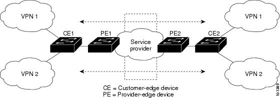
Multi-VRF CE: Multi-VRF CE is a network optimization feature that allows a single Customer Edge (CE) device to support multiple VPNs.

Cisco C9350 Series Switches

Cisco C9610 Series Switches

Multi-VRF CE

Multi-VRF CE is a network optimization feature that allows a single Customer Edge (CE) device to support multiple Virtual Private Networks (VPNs). Because the CE device can support multiple VPNs, each VPN can use overlapping IP addresses. This capability is particularly useful in environments where multiple distinct network segments or customers need to share a common physical infrastructure while maintaining complete isolation.

How Multi-VRF CE works

Summary

In Multi-VRF CE, a CE device can be configured to support multiple VPNs by maintaining separate VRF tables for each VPN. Each VRF functions as an independent virtual router, providing logical separation of customer traffic even when IP address spaces overlaps. These VRFs are associated with one or more Layer 3 interfaces on the CE device, and when packets arrive on these interfaces, the router uses the input interface to determine the corresponding VRF. This mechanism allows the input interface to act as a key for distinguishing and segregating traffic belonging to different VPNs, ensuring proper routing and isolation between them.

Figure shows a Multi-VRF network with multiple VLANs, CE devices, PE devices, and the service provider.

Workflow

Figure 1. Multi-VRF CE topology

CE1 and CE2 are layer 3 switches while PE1 and PE2 are routers connected to the service provider. Each PE is connected to one CE while each CE has more than one VPN connected to it.

VLAN ID and policy label

In Multi-VRF CE, when the Layer 3 interface, on a CE switch, is associated to a VRF, it establishes a mapping between the VLAN ID of that interface and a policy label (PL). Each VRF has its VLAN IDs mapped to distinct policy labels, which help differentiate VRFs during packet processing.

This VLAN ID-PL mapping is stored in Multi-VRF CE data structures that manage the relationships between VLANs and VRFs, while the VLAN ID and policy label information are recorded in the VLAN database.

According to the VRF policies, the switch identifies and routes traffic correctly, ensuring proper separation and forwarding of VPN traffic.

When a new VPN route is learned, the Layer 3 setup function retrieves the policy label using the VLAN ID of the ingress port and adds the policy label along with the new route to the multi-VRF CE routing section. If the packet arrives from a routed port, the port’s internal VLAN ID is used; if it arrives from a Switched Virtual Interface (SVI), the VLAN number itself is used. This process ensures accurate VRF identification and routing for incoming packets, maintaining logical separation of customer traffic even when IP address spaces overlap.

After multi-VRF CE is configured, the Layer 3 forwarding table is conceptually partitioned into two sections:

  • The multi-VRF CE routing section contains the routes from different VPNs.

  • The global routing section contains routes to non-VPN networks, such as the Internet.

How packet-forwarding works in Multi-VRF CE

Summary

The key components involved in packet-forwarding are:

Workflow

In a multi-VRF-CE-enabled network, packet forwarding involves these steps:

  1. When the CE switch receives a packet from a VPN, it uses the input policy label to look up the corresponding VPN routing table. If a matching route is found, the packet is forwarded to the connected PE device.
  2. When the ingress PE receives a packet from the CE, it performs a VRF lookup based on the incoming interface or label. Upon finding a route, the PE adds the appropriate MPLS label(s) to the packet and forwards it into the MPLS network.
  3. When the egress PE receives a packet from the MPLS network, it removes the outer MPLS label(s) and uses the label to identify the correct VPN routing table. It then performs a route lookup and forwards the packet to the appropriate adjacency or interface.
  4. When the CE receives a packet from the egress PE, it uses the input policy label to perform a VPN routing table lookup. If a route is found, the CE forwards the packet within the VPN accordingly.

BGP and Multi-VRF CE

A Multi-VRF CE network with BGP configured as the routing protocol has the following components:

  • VPN route target communities: Lists of all other members of a VPN community. You need to configure VPN route targets for each VPN community member.

  • Multiprotocol BGP peering of VPN community PE routers: Propagates VRF reachability information to all members of a VPN community. You need to configure BGP peering in all PE routers within a VPN community.

  • VPN forwarding: Transports all traffic between all VPN community members across a VPN service-provider network.

Guidelines for Multi-VRF CE configuration

This section provides configuration guidelines for Multi-VRF CE:

  • Overlapping IP addresses are allowed in different VPNs.

  • The switch supports configuring VRF by using physical ports, VLAN SVIs, or a combination of both.

  • SVIs can connect through an access port or a trunk port.

  • A customer can use multiple VLANs as long as they do not overlap with those of other customers. A customer’s VLANs are mapped to a specific routing table ID . Table IDs are used to identify the appropriate routing tables stored on the switch.

  • The switch supports one global network and up to 256 VRFs.

  • Most routing protocols such as BGP, OSPF, RIP, and static routing) can be used between the CE and the PE.

  • We recommend using external BGP (EBGP) for these reasons:

    • BGP does not require multiple algorithms to communicate with multiple CEs.

    • BGP is designed to pass routing information between systems run by different administrations.

    • BGP makes it easy to pass route attributes to the CE.

  • Multi-VRF CE does not affect the packet switching rate.

  • You can enable VRF on a private VLAN and route a private VLAN's traffic through a specific VRF.

  • Multi-VRF CE does not support all MPLS-VRF functionality. It does not support label exchange, LDP adjacency, or labeled packets.

  • VPN multicast is not supported.

  • You cannot enable VRF when policy-based routing (PBR) is enabled on an interface, and the reverse or enable PBR on an interface configured with VRF.

  • You cannot enable VRF when Web Cache Communication Protocol (WCCP) is enabled on an interface or enable WCCP on an interface configured with VRF.

How to configure Multi-VRF CE

The following sections provide configuration information about Multi-VRF CE.

Default Multi-VRF CE configuration

This section talks about the default VRF configurations.
Table 1. Default VRF Configuration

Feature

Default setting

VRF

Disabled. No VRFs are defined.

Maps

No import maps, export maps, or route maps are defined.

VRF maximum routes

Fast Ethernet switches: 8000

Gigabit Ethernet switches: 12000

Forwarding table

The default for an interface is the global routing table.

Configure VRFs

Perform this task to configure VRFs.

Procedure


Step 1

enable

Example:

Device> enable

Enables privileged EXEC mode.

Enter your password, if prompted.

Step 2

configure terminal

Example:

Device# configure terminal

Enters global configuration mode.

Step 3

ip routing

Example:

Device(config)# ip routing

Enables IP routing.

Step 4

ip vrf vrf-name

Example:

Device(config)# ip vrf vpn1

Defines the VRF and enters VRF configuration mode.

Step 5

rd route-distinguisher

Example:

Device(config-vrf)# rd 100:2

Creates a VRF table by specifying a route distinguisher. Enter either an AS number and an arbitrary number (xxx:y) or an IP address and arbitrary number (A.B.C.D:y)

Step 6

route-target{export | import | both} route-target-ext-community

Example:

Device(config-vrf)# route-target import 100:2

Creates a list of import, export, or import and export route target communities for the specified VRF.

Enter either an AS system number and an arbitrary number (xxx:y) or an IP address and an arbitrary number (A.B.C.D:y). The route-target-ext-community should be the same as the route-distinguisher entered in Step 4.

Step 7

import map route-map

Example:

Device(config-vrf)# import map importmap1

(Optional) Associates a route map with the VRF.

Step 8

interface interface-id

Example:

Device(config-vrf)# interface gigabitethernet 1/0/2

Specifies the Layer 3 interface to be associated with the VRF, and enter interface configuration mode. The interface can be a routed port or an SVI.

Step 9

ip vrf forwarding vrf-name

Example:

Device(config-if)# ip vrf forwarding vpn1

Associates the VRF with the Layer 3 interface.

Step 10

end

Example:

Device(config-if)# end

Returns to privileged EXEC mode.


Configure a VPN routing session

Perform this task to configure a routing protocol between the PE and CE device.


Note


This task shows how to configure an OSPF routing protocol but the same process can be used for other routing protocol such as RIP, EIGRP, or BGP.


Procedure


Step 1

enable

Example:

Device> enable

Enables privileged EXEC mode.

Enter your password, if prompted.

Step 2

configure terminal

Example:

Device# configure terminal

Enters global configuration mode.

Step 3

router ospf process-id vrf vrf-name

Example:

Device(config)# router ospf 1 vrf vpn1

Enables OSPF routing, specifies a VPN forwarding table, and enter router configuration mode.

Note


If you are configuring an EIGRP routing process to run within a VRF instance, you must configure an autonomous-system number by entering the autonomous-system autonomous-system-number command in address-family configuration.

Step 4

log-adjacency-changes

Example:

Device(config-router)# log-adjacency-changes

(Optional) Logs changes in the adjacency state. This is the default state.

Step 5

redistribute bgp autonomous-system-number subnets

Example:

Device(config-router)# redistribute bgp 10 subnets

Sets the switch to redistribute information from the BGP network to the OSPF network.

Step 6

network network-number area area-id

Example:

Device(config-router)# network 1 area 2

Defines a network address and mask on which OSPF runs and the area ID for that network address.

Step 7

end

Example:

Device(config-router)# end

Returns to privileged EXEC mode.

Step 8

show ip ospf process-id

Example:

Device# show ip ospf 1

Verifies the configuration of the OSPF network.

Step 9

copy running-config startup-config

Example:

Device# copy running-config startup-config

(Optional) Saves your entries in the configuration file.


Configure BGP PE to CE routing sessions

Perform this task to configure BGP PE to CE routing sessions.

Procedure


Step 1

enable

Example:

Device> enable

Enables privileged EXEC mode.

Enter your password, if prompted.

Step 2

configure terminal

Example:

Device# configure terminal

Enters global configuration mode.

Step 3

router bgp autonomous-system-number

Example:

Device(config)# router bgp 2

Configures the BGP routing process with the AS number passed to other BGP routers, and enter router configuration mode.

Step 4

network network-number mask network-mask

Example:

Device(config-router)# network 5 mask 255.255.255.0

Specifies a network and mask to announce using BGP.

Step 5

redistribute ospf process-id match internal

Example:

Device(config-router)# redistribute ospf 1 match internal

Sets the switch to redistribute OSPF internal routes.

Step 6

network network-number area area-id

Example:

Device(config-router)# network 5 area 2

Defines a network address and mask on which OSPF runs and the area ID for that network address.

Step 7

address-family ipv4 vrf vrf-name

Example:

Device(config-router)# address-family ipv4 vrf vpn1

Defines BGP parameters for PE to CE routing sessions, and enter VRF address-family mode.

Step 8

neighbor address remote-as as-number

Example:


Device(config-router)# neighbor 10.1.1.2 remote-as 2

Defines a BGP session between PE and CE routers.

Step 9

neighbor address activate

Example:

Device(config-router)# neighbor 10.2.1.1 activate

Activates the advertisement of the IPv4 address family.

Step 10

end

Example:

Device(config-router)# end

Returns to privileged EXEC mode.

Step 11

show ip bgp [ipv4] [neighbors]

Example:

Device# show ip bgp ipv4 neighbors

Verifies BGP configuration.

Step 12

copy running-config startup-config

Example:

Device# copy running-config startup-config

(Optional) Saves your entries in the configuration file.


Monitor Multi-VRF CE

You can use any of these command to monitor Multi-VRF CE.
Table 2. Command to monitor Multi-VRF CE

Command

Purpose

show ip protocols vrf vrf-name

Displays routing protocol information associated a VRF.

show ip route vrf vrf-name [connected] [protocol [as-number]] [list] [mobile] [odr] [profile] [static] [summary] [supernets-only]

Displays IP routing table information associated a VRF.

show ip vrf [brief | detail | interfaces] [vrf-name]

Displays information about the defined VRF.

show ip arp vrf vrf-name

Displays the ARP table in the specified VRF.

ping vrf vrf-name ip-host

Displays the ARP table in the specified VRF.