Feature history for NAT
This table provides release and platform support information for the features explained in this module.
These features are available in all the releases subsequent to the one they were introduced in, unless noted otherwise.
|
Release |
Feature Name and Description |
Supported Platform |
|---|---|---|
|
Cisco IOS XE 26.2.1ea |
NAT: Network Address Translation (NAT) feature support has been introduced. |
Cisco C9550 Series Smart Switches |
|
Cisco IOS XE 26.1.1 |
NAT: Network Address Translation (NAT) feature support has been introduced. |
Cisco C9610 Series Smart Switches |
|
Cisco IOS XE 17.18.1 |
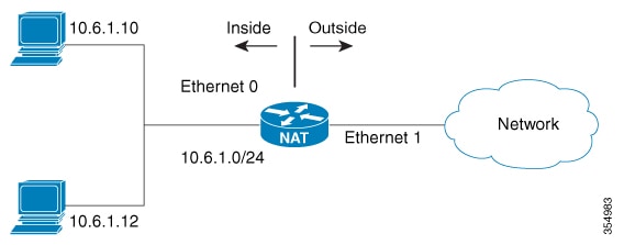
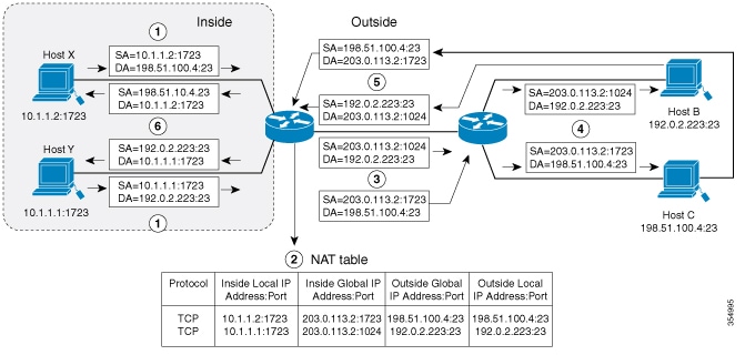
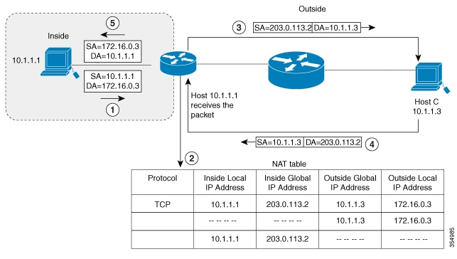
NAT: Network Address Translation enables private IP networks using unregistered addresses to communicate with external networks by translating internal private addresses into globally routable addresses. This provides IP address conservation and security by hiding internal network addresses behind a single public address, facilitating Internet connectivity for internal users. |
Cisco C9350 Series Smart Switches |

 Feedback