- Information About VXLAN
- Configuring VXLAN
- Enabling VXLANs
- Configuring VNI Service Instances
- Mapping VLAN to VNI
- Creating an VTEP and NVE Interface
- Configuring vPC Peer-link
- Configuring L3 Interface on VXLAN Tunnel/Hypervisor VLAN
- Configuring L3 Interface for IP Cloud Connectivity
- Configuring L3 Interface on Tenant Bridge-Domains/VNIs in L3 Gateway
- Disabling VXLANs
- Verifying the VXLAN Configuration
- Configuration Examples
- Feature History for VXLAN Flood and Learn
Configuring VXLAN
Flood and Learn
This chapter contains the following sections:
- Information About VXLAN
- Configuring VXLAN
- Verifying the VXLAN Configuration
- Configuration Examples
- Feature History for VXLAN Flood and Learn
Information About VXLAN
VXLAN with vPC Overview
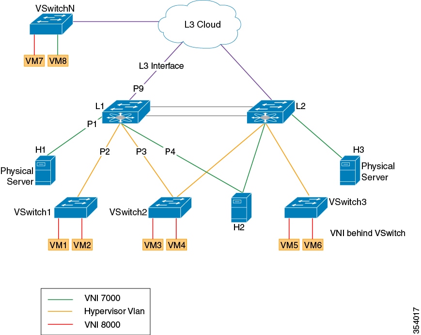
The vSwitch can be dually connected to the vPC via a hypervisor VLAN. The VTEP on L1 and L2 is identified by the same IP address. vPC is active/active for East-West traffic (from the physical server to the VMs behind vSwitch). It is active/standby with the elected forwarder for packets from North-South traffic.
Active/Active scheme:
-
Both switches perform encapsulation and decapsulation between the VXLAN tunnel (on the access side) and the physical servers. To prevent duplicate copies, we rely on the VSL bit.
-
If a packet comes in on hypervisor VLAN on a switch it is bridged to other peers via the peerlink. The decapsulated copy is prevented from going over the peer link (using reserved ftag CBL scheme). Both switches bridge locally on the hypervisor VLAN and decapsulate and bridge in the tenant VNI (the VSL bit prevents a duplicate copy from being sent to the vPC legs).
-
If a packet comes into the tenant VNI from the physical server, it is bridged to the vPC peer. The VXLAN tunnel encapsulated copy is blocked from going over the peerlink using LTL+1 logic.
Active/Standby scheme:
VXLAN Layer 2 Gateway
The VXLAN Layer 2 gateway bridges traffic between physical servers and VM’s behind vSwitches that are in the same VNI.
-
Connectivity of vSwitches to Cisco Nexus 7000 is via a Layer 2 port through a VLAN which is called a hypervisor VLAN. One of the requirements for a VXLAN gateway is that the hypervisor VLAN should be Layer 3 enabled (SVI configured) and be a member of the core VRF.
-
Traffic from the physical server is mapped to segment (VNI) using VSI configuration.
-
Traffic from VMs behind vSwitches are encapsulated in VXLAN format with VNI information from the server to which it belongs. The VNI identifies the bridge-domain that both the physical server and the virtual servers are a part.
-
For packets coming from vSwitches, the Layer 2 VXLAN gateway strips the VXLAN header and identifies the bridge-domain before bridging the packet to the physical server. Similarly, when physical servers talk to VM’s behind vSwitches, the VXLAN header is appended with appropriate VNI information before sending it to the vSwitches.
-
VXLAN uses the control multicast group for broadcast, unknown unicast and multicast (BUM) traffic. When the control multicast group is configured on the vSwitch, it sends IGMP reports to the Cisco Nexus 7000 switch on the hypervisor VLAN . This results in Layer 2 multicast state creation for the control multicast group on the hypervisor VLAN. Since the hypervisor VLAN is Layer 3 enabled on the core VRF, it triggers a PIM join and Layer 3 multicast state creation. Thus, BUM traffic is bridged to locally connected vSwitches via Layer 2 multicast bridging and to remote vSwitches behind Layer 3 cloud via Layer 3 multicast routing.
VXLAN Layer 3 Gateway
Layer 3 VXLAN gateway enables routing between different VNIs. The Cisco Nexus 7000 can be placed as a pure Layer 3 routing box, which does inter VNI routing or it can be placed along with Layer 2 VXLAN gateway functionality. To enable Layer 3 VXLAN functionality, BDI has to be configured on the tenant VNI and the tenant VRF has to be different from the core VRF.
All VMs and physical servers and VNIs belonging to the same tenants can communicate. Any packet that needs to be routed across VNIs needs to be sent to the Layer 3 gateway switch, by setting the outer IP to the Layer 3 gateway IP, and the inner DMAC to be the Layer 3 gateway MAC.
The implications of the limited Layer 3 gateway functionality are the following:
-
Since the Layer 3 gateway is centralized, there is no need to run control protocols (to advertise the host reachability information). When the Layer 3 gateway receives the packet, it looks at the Layer 3 header information to route the packet (to the destination subnet/VNI), but the actual remote switch to which the packet needs to be forwarded is resolved at the Layer 2 level, which is done via data plane learning.
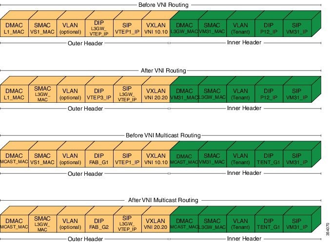
For example, in the above diagram the packets from VM31 (1.1.1.x) to P12 (2.2.2.x) are resolved at the Layer 3 level to go to SVI_VNI_20.20. After the routing, the destination VTEP, that is responsible for the destination host, is identified at the Layer 2 level. There are two cases to consider here:
-
If the switch that runs the Layer 3 gateway functionality does not run Layer 2 gateway functionality, that is, participates in the data plane learning, it has to flood the post-routed packet to all Layer 2 gateways through the multicast tree.
-
If the switch runs Layer 3 gateway and Layer 2 gateway functionality, the switch can resolve the destination VTEP at the Layer 2 level, and can forward the packet to the correct VTEP by itself.
Since Layer 2 gateway and Layer 3 gateway functionalities are tightly integrated from the configuration perspective (Layer 3 gateway is achieved by configuring the BDIs for bridge-domains corresponding to the VNIs), case (1) will not be applicable in the Cisco Nexus 7000, and only case (2) is supported.
Since there is a centralized Layer 3 gateway, any multicast packet that needs to be routed across multiple VNIs, will be have to be replicated multiple times (one for each VNI).
In the above example, if P12 is interested in traffic initiated by VM31, the Layer 3 gateway will have to send two copies of the packet (one for VNI 20.20, and, one for VNI 30.30).
Also, note that routing between VNI and Layer 3 interfaces can be supported only for those interfaces that are local to the Layer 3 gateway, assuming those local Layer 3 interfaces are configured in the same tenant VRF as the VNI. One possible solution would be to have a separate Layer 3 connection between those leaf switches and spine (Layer 3 gateway) switch, configure them all in tenant VRF, run OSPF (or IS-IS) for that tenant VRF, and run PIM to draw multicast traffic along the tree.
VXLAN Licensing Information
The following table lists the license package for VXLAN Flood and Learn:
|
Feature License |
Product ID |
|
Enterprise Services Package LAN_ENTERPRISE_SERVICES_PKG |
N7K-LAN1K9 N77-LAN1K9 |
Guidelines and Limitations for VXLAN
VXLAN has the following guidelines and limitations:
-
VxLAN and Fabric Path features cannot be enabled on the same VDC.
-
4 VTEP interfaces per VDC are supported. The total number of remote VTEPs is 1K per VDC.
-
1K VNIs are allowed per VDC.
-
1k BDIs are allowed per system.
-
Bidir in underlay is not supported on vPC VXLAN Gateways.
-
In vPC Flood and Learn deployments with F3 modules, the vPC peer-link must be on an isolated ASIC instance from the L3 core ports. This restriction does not apply to BGP EVPN deployments.
-
The number of IPv4 unicast routes supported is 64K shared with multicast routes.
-
Number of IPv4 Multicast Groups is 32K due to software limitation.
-
Maximum number of MAC addresses learned (local MACs and remote MACs) is 64K per F3 ASIC. (F3 MAC table size is 64K).
-
VXLAN with IGMP snooping on VTEP tunnel interface is supported. You can configure ip igmp snooping disable-nve-static-router-port globally or per vlan to learn snooping states dynamically.
-
VXLAN with Ingress replication using control plane is not supported.
-
You can send Layer 3 end-to-end traffic with a maximum packet size of 9192 between VSI ports in different VNI segments.
-
Layer 3 traffic will be dropped if the MTU packet size is greater than 9192.
-
Inner VLAN class of service (CoS) needs to be propagated from ingress to egress in VXLAN. At the encap side, CoS value will be copied to outer differentiated services code point (DSCP) and on the decap side DSCP QOS will be copied back to egress VLAN COS.
-
vPC peer-link can carry both global VLAN and bridge-domains that are having VXLAN enabled.
-
MLD snooping on bridge-domain with VXLAN is not supported.
-
ACL and QoS on a VTEP tunnel are not supported.
-
Layer 3 VXLAN gateways are supported.
-
PVLAN with VXLAN is not supported.
-
Extending VLAN/VNI with OTV, VPLS, NV-GRE, and Layer 2 LISP when VXLAN is enabled is not supported due to hardware restrictions in the F3 ASIC.
-
Extending Layer 2 MPLS network directly with VXLAN is not supported. Layer 2 MPLS has to be terminated and connected as a CE port for VXLAN extension due to forwarding restrictions.
-
Interop with IPGRE is not supported.
-
Interop with Layer 3 LISP is not supported.
-
F3 SPAN feature does not support spanning L3 egress multicast packets.
-
Netflow is not supported on VTEP interface.
-
Netflow on VXLAN-enabled bridge domains is not supported.
-
FEX ports are not supported as edge ports for VXLAN enabled bridge-domains.
-
Extending global VLANs using VXLAN is not supported.
-
BPDUs are not sent over the VTEP tunnel.
-
Layer 3 Multicast - SSM in the core is not supported.
-
MIB/XML support for VXLAN related changes is not supported.
-
VXLAN encapsulation of an outer header with an IPv6 header is not supported.
-
In VXLAN vPC Setup, RP should be configured on L3 core network. Direct connectivity between L2 gateway and vPC L3 gateway without L3 core in between is not supported.
-
Any Source Multicast (ASM) is supported. Bidirectional PIM is supported on a single, non-vPC leaf switch.
-
Physical port vPC for Vn-segment Service Instance (VSI) is not supported.
-
The following Interface NVE counters are supported.
-
SPAN is not supported for NVE tunnel interfaces.
-
Equal cost multipath (ECMP) on the core is based on inner packet (DMAC, SMAC) combination.
-
Maximum 64 MST instances are supported.
-
MST scale limit is 300K logical ports on unidimensional setup.
-
When vPC peer-link flap, Mac addresses will be flushed for orphan and vPC ports. End point needs to re-ARP.
-
32 VSI encapsulation profiles are supported per interface.
-
SSM is not supported
-
Bi-Dir multicast mode is not supported for vPC
-
IGMP Snooping Layer2 Multicast Mac lookup mode is not supported.
-
IPv6 for Multicast is not supported.
-
Hypervisor VLANs can be configured using regular VLAN and trunk or access port configurations.
-
vPC peer-link can carry both global VLANs and bridge-domains that are VXLAN enabled.
- Considerations for VXLAN Deployment
- vPC Considerations for VXLAN Deployment
- Network Considerations for VXLAN Deployments
- Considerations for the core VRF
Considerations for VXLAN Deployment
-
A loopback address is required when using the source-interface config command. The loopback address represents the local VTEP IP.
-
For the Network Virtualization Endpoint (NVE) source loop back address, secondary address should be same on both the vPC peers and the primary address should be different.
-
To establish IP multicast routing in the core, IP multicast configuration, PIM configuration, and RP configuration is required.
-
VTEP to VTEP unicast reachability can be configured through any IGP protocol.
vPC Considerations for VXLAN Deployment
-
Bind NVE to a loopback address that is separate from other loopback addresses that are required by Layer 3 protocols. A best practice is to use a dedicated loopback address for VXLAN.
-
The loopback address used by NVE needs to be configured to have a primary IP address and a secondary IP address.
-
The secondary IP address is used for all VXLAN traffic that includes multicast and unicast encapsulated traffic.
-
VPC peers must have identical configurations as listed below:
-
For multicast, the VPC node that receives the (S, G) join from the RP (rendezvous point) becomes the DF (designated forwarder). On the DF node, encap routes are installed for multicast.
Decap routes are installed based on the election of a decapper from between the VPC primary node and the VPC secondary node. The winner of the decap election is the node with the least cost to the RP or the source. However, if the cost to the RP is the same for both nodes, the VPC primary node is elected.
The winner of the decap election has the decap mroute installed. The other node does not have a decap route installed.
-
On a VPC device, BUM traffic (broadcast, unknown-unicast, and multicast traffic) from hosts is replicated on the vPC peer-link. A copy is made of every native packet and each native packet is sent across the vPC peer-link to service orphan-ports connected to the peer VPC switch.
To prevent traffic loops in VXLAN networks, native packets ingressing the vPC peer-link cannot be sent to an uplink. However, if the peer switch is the encapper, the copied packet traverses the vPC peer-link and is sent to the uplink.
-
When vPC peer-link is shut, the loopback primary address is used as the source IP address for encapsulation by both vPC switches.

Note
Orphans connected to the VPC secondary will experience loss of traffic for the period that the vPC peer-link is shut. This is similar to Layer 2 orphans in a VPC secondary of a traditional VPC setup.
-
When vPC peer-link is no-shut, the NVE loopback secondary address is used.
-
For VPC, the loopback interface has 2 IP addresses: the primary IP address and the secondary IP address.
The primary IP address is unique and is used by Layer 3 protocols.
The secondary IP address on loopback is necessary because the interface NVE uses it for the VTEP IP address. The secondary IP address must be same on both vPC peers.
-
The VPC peer-gateway feature must be enabled on both peers.
As a best practice, use peer-switch, peer gateway, ip arp sync, ipv6 nd sync configurations for improved convergence in VPC topologies.
The following is an example (best practice) of a VPC configuration:
switch# sh ru vpc

version 6.1(2)I3(1)
feature vpc
vpc domain 2
  peer-switch
  peer-keepalive destination 172.29.206.65 source 172.29.206.64
  peer-gateway
  ipv6 nd synchronize
  ip arp synchronize
-
On a VPC pair, shutting down NVE or NVE loopback on one of the VPC nodes is not a supported configuration. This means that traffic fail over on one-side NVE shut or one-side loopback shut is not supported.
- Redundant anycast RPs configured in the network for multicast load-balancing and RP redundancy are supported on VPC VTEP topologies.
-
The following are the examples of SVI with PIM enabled:
switch# show run interface BDI3

interface BDI3
  description special_svi_over_mct
  no shutdown
  ip address 30.2.1.1/30
  ip pim sparse-mode


switch# show run interface BDI3

interface BDI3
 description special_svi_over_vPC peer-link no shutdown
 ipv6 address FE80::290:27FF:FE8C:B709
 ip pim sparse-mode
Note
The SVI must be configured on both VPC peers and requires PIM to be enabled.
-
As a best practice when changing the secondary IP address of an anycast VPC VTEP, the NVE interfaces on both the VPC primary and the VPC secondary should be shut before the IP changes are made.
Network Considerations for VXLAN Deployments
-
MTU Size in the Transport Network
Due to the MAC-to-UDP encapsulation, VXLAN introduces 50-byte overhead to the original frames. Therefore, the maximum transmission unit (MTU) in the transport network needs to be increased by 50 bytes. If the overlays use a 1500-byte MTU, the transport network needs to be configured to accommodate 1550-byte packets at a minimum. Jumbo-frame support in the transport network is required if the overlay applications tend to use larger frame sizes than 1500 bytes.
-
ECMP and LACP Hashing Algorithms in the Transport Network
As described in a previous section, Cisco Nexus 7000 Series Switches introduce a level of entropy in the source UDP port for ECMP and LACP hashing in the transport network. As a way to augment this implementation, the transport network uses an ECMP or LACP hashing algorithm that takes the UDP source port as an input for hashing, which achieves the best load-sharing results for VXLAN encapsulated traffic.
-
Multicast Group Scaling
The VXLAN implementation on Cisco Nexus 7000 Series Switches uses multicast tunnels for broadcast, unknown unicast, and multicast traffic forwarding. Ideally, one VXLAN segment mapping to one IP multicast group is the way to provide the optimal multicast forwarding. It is possible, however, to have multiple VXLAN segments share a single IP multicast group in the core network. VXLAN can support up to 16 million logical Layer 2 segments, using the 24-bit VNID field in the header. With one-to-one mapping between VXLAN segments and IP multicast groups, an increase in the number of VXLAN segments causes a parallel increase in the required multicast address space and the amount of forwarding states on the core network devices. At some point, multicast scalability in the transport network can become a concern. In this case, mapping multiple VXLAN segments to a single multicast group can help conserve multicast control plane resources on the core devices and achieve the desired VXLAN scalability. However, this mapping comes at the cost of suboptimal multicast forwarding. Packets forwarded to the multicast group for one tenant are now sent to the VTEPs of other tenants that are sharing the same multicast group. This causes inefficient utilization of multicast data plane resources. Therefore, this solution is a trade-off between control plane scalability and data plane efficiency.
Despite the suboptimal multicast replication and forwarding, having multiple-tenant VXLAN networks to share a multicast group does not bring any implications to the Layer 2 isolation between the tenant networks. After receiving an encapsulated packet from the multicast group, a VTEP checks and validates the VNID in the VXLAN header of the packet. The VTEP discards the packet if the VNID is unknown to it. Only when the VNID matches one of the VTEP’s local VXLAN VNIDs, does it forward the packet to that VXLAN segment. Other tenant networks will not receive the packet. Thus, the segregation between VXLAN segments is not compromised.
Considerations for the core VRF
The following are considerations for the configuration of the core VRF:
-
On the VTEP device:
-
Enable and configure IP multicast.
-
Create and configure a loopback interface with a /32 IP address.
-
Enable IP multicast on the loopback interface.
-
Advertise the loopback interface/32 addresses through the routing protocol that runs in the transport network.
-
Enable IP multicast on the uplink outgoing physical interface.
-
-
Throughout the transport network:
ISSU Support
The following are the ISSU support details for VXLAN flood and learn deployment:
-
Cisco Nexus 7000 Series switches running Cisco NX-OS Release 6.2.10 or 6.2.12.
-
F2E, M2, and F3 modules.
-
Virtual Device Context (VDC) Types:
Supported ISSU Steps:
Configuring VXLAN
Enabling VXLANs
switch# configure terminal
switch(config)# feature nv overlay
switch(config)# feature vni
switch(config)# vni 7000
switch(config)# copy running-config startup-config
Configuring VNI Service Instances
The following example shows how to configure VNI service instances:
config t
       encapsulation profile vni vsi_100_to_7000
            dot1q 100 vni 7000
  interface e1/1
      service instance 1 vni
						no shut down
      encapsulation profile vsi_100_to_7000
Mapping VLAN to VNI
The following example shows how to map an encapsulation profile to a VNI:
switch# configure terminal
switch(config)# system bridge-domain 10-50
switch(config)# bridge-domain 100
switch(config)# member vni 7000
Creating an VTEP and NVE Interface
An NVE interface is the overlay interface that terminates VXLAN tunnels.
There is a one-on-one mapping between NVE interface configuration and the source interface. Source interface used under a NVE cannot be reused.
You can create and configure an NVE (overlay) interface with the following:
The following example shows how to create a VTEP / NVE interface:
switch# configure terminal
switch(config)# interface nve 1
switch(config-if)# source-interface loopback 10
switch(config-if)# member vni 7000 mcast-group 225.1.1.1
switch(config-if)# member vni 8000 mcast-group 226.1.1.1
switch# configure terminal
switch(config)# interface loopback 10
switch(config-if)# ip address 10.1.1.1/32
switch(config-if)# vrf member core
Configuring vPC Peer-link
| Command or Action | Purpose |
|---|
The following example shows how to configure vPC peer-link:
switch# configure terminal
switch(config)# interface e1/10
switch(config-if)# switchport mode trunk
switch(config-if)# vpc peer-link
Configuring L3 Interface on VXLAN Tunnel/Hypervisor VLAN
| Command or Action | Purpose |
|---|
The following example shows how to configure L3 interface on VXLAN tunnel/hypervisor VLAN:
switch# configure terminal
switch(config)# interface vlan 300
switch(config-if)# ip address 11.1.1.1/24
switch(config-if)# vrf member core
Configuring L3 Interface for IP Cloud Connectivity
| Command or Action | Purpose |
|---|
The following example shows how to configure L3 interface for IP cloud connectivity:
switch# configure terminal
switch(config)# interface e7/1
switch(config-if)# no switchport
switch(config-if)# ip address 11.1.1.1/24
switch(config-if)# vrf member core
Configuring L3 Interface on Tenant Bridge-Domains/VNIs in L3 Gateway
| Command or Action | Purpose | |
|---|---|---|
| Step 1 |
configure
terminal
|
Enters global configuration mode. |
| Step 2 |
feature interface-vlan
|
Enables the creation of BDI interfaces. |
| Step 3 | interface
bridge-domain
number
|
Enters interface configuration mode. |
| Step 4 | ip address
address
|
Configures the IP address on the interface. |
| Step 5 | vrf member
tenant
|
Configures the VRF member. |
| Step 6 | hsrp
var
|
Creates an HSRP group and enters HSRP configuration mode. |
| Step 7 | ip address
address
|
Configures the virtual IP address for the HSRP group and enables the group. Repeat steps 1-5 to configure another bridge-domain interface and HSRP. |
The following example shows how to configure L3 interface on tenant bridge-domains/VNIs in L3 gateway:
feature interface-vlan
interface bridge-domain 100
     ip address 50.1.1.2/24
     vrf member tenant
     hsrp 50
         ip address 50.1.1.1
feature interface-vlan
interface bridge-domain 200
    ip address 60.1.1.2/24
    vrf member tenant
     hsrp 60
     ip address 60.1.1.1
Disabling VXLANs
| Command or Action | Purpose | |
|---|---|---|
| Step 1 |
configure
terminal
|
Enters configuration mode. |
| Step 2 |
no
feature
vni
|
Disables the global mode for all VXLAN bridge domains |
| Step 3 | no
feature nv
overlay
|
Disables the VXLAN feature. |
| Step 4 | no
bridge-domain
|
Disables bridging to map VLAN. |
| Step 5 | no
member
vni
|
Dissociates VXLAN VNIs from the NVE interface. |
| Step 6 | no
vni
|
Removes the VXLAN segment ID to which the VLAN is mapped. |
| Step 7 |
copy running-config
startup-config
| (Optional)
Saves the change persistently through reboots and restarts by copying the running configuration to the startup configuration. |
Verifying the VXLAN Configuration
To display the VXLAN configuration information, enter one of the following commands:
|
Command |
Purpose |
|---|---|
|
show tech-support vxlan |
Displays related VXLAN tech-support information. |
|
show logging level nve |
Displays logging level. |
|
show tech-support nve |
Displays related NVE tech-support information. |
|
show run interface nve x |
Displays NVE overlay interface configuration. |
|
show nve interface nve x |
Displays NVE overlay interface status. |
|
show interface nve x |
Displays all the counters of an NVE interface. |
|
show nve peers |
Displays NVE peer status. |
|
show bridge-domain |
Displays the bridge domain information. |
|
show run vni |
Displays the VXLAN VNI configuration. |
|
show interface nve counters |
Displays the NVE counters in an interface. |
|
show interface bdi |
Displays the configuration summary of the corresponding BDI. |
|
show vni x |
Displays the list of all VNIs |
|
show ip mroute |
Displays information about mroute entries in the mroute table. |
|
show nve VXLAN-params |
Displays VXLAN parameters, such as VXLAN destination or UDP port. |
|
show nve internal platform interface nve 1 detail |
Displays NVE overlay internal detailed information. |
|
show nve vxlan-params |
Displays VXLAN parameters, such as VXLAN destination or UDP port. |
Configuration Examples
- Example of VXLAN Flood and Learn Configuration
- Example of Verifying VXLAN Flood and Learn Configuration
Example of VXLAN Flood and Learn Configuration
The following example shows the VXLAN Flood and Learn configuration.
VTEP-1:
feature pim
system bridge-domain 50,75
feature nv overlay
feature interface-vlan

feature vni
vni 30000
vni 50000

ip route 10.10.10.2/32 Ethernet10/1 10.1.1.2
ip pim rp-address 10.1.1.1 group-list 209.165.0.0/4

bridge-domain 50
bridge-domain 75

encapsulation profile vni VSI_50_TO_5000
  dot1q 50  vni 5000
encapsulation profile vni VSI_75_TO_7500
    dot1q 75  vni 7500
bridge-domain 50
  member vni 5000
bridge-domain 75
  member vni 7500

interface nve1
  no shutdown
  source-interface loopback10
  member vni 5000 mcast-group 209.165.1.1
  member vni 7500 mcast-group 209.165.1.1

interface Bdi50
   no shutdown
   ip address 10.50.50.50/24

interface Bdi75
   no shutdown
   ip address 10.75.75.75/24

interface Ethernet7/17
  no switchport
  no shutdown
  service instance 1 vni
    no shutdown
    encapsulation profile VSI_50_TO_5000  default
  service instance 2 vni
    no shutdown
    encapsulation profile VSI_75_TO_7500 default

interface Ethernet10/1
  no switchport
  ip address 10.1.1.1/30
  ip pim sparse-mode
  no shutdown

interface loopback10
  ip address 10.10.10.1/32
  ip pim sparse-mode
Note | The internal interface on the VTEP is configured as a layer-3 port. However, there is no IP assigned to it. It is also important to note that the BD value defined on the VTEP does not have to match the VLAN ID on the device from which you are sending the traffic. However, the dot1q to VNI mapping defined in the encapsulation profile, which is called under the service instance on the internal interface, must match the VLAN ID on the device from which you are sending the traffic. |
VTEP-2:
feature pim
system bridge-domain 50,75
feature nv overlay
feature interface-vlan

feature vni
vni 32000
vni 52000

ip route 10.10.10.1/32 Ethernet10/7 10.1.1.1
ip pim rp-address 10.1.1.1 group-list 209.165.0.0/4

bridge-domain 50
bridge-domain 75

encapsulation profile vni VSI_50_TO_5000
  dot1q 50  vni 5000
encapsulation profile vni VSI_75_TO_7500
    dot1q 75  vni 7500
bridge-domain 50
  member vni 5000
bridge-domain 75
  member vni 7500

interface nve1
  no shutdown
  source-interface loopback10
  member vni 5000 mcast-group 209.165.1.1
  member vni 7500 mcast-group 209.165.1.1

interface Bdi50
 no shutdown
 ip address 10.50.50.51/24

interface Bdi75
 no shutdown
 ip address 10.75.75.76/24

interface Ethernet7/30
  no switchport
  no shutdown
  service instance 1 vni
    no shutdown
    encapsulation profile VSI_50_TO_5000  default
  service instance 2 vni
    no shutdown
    encapsulation profile VSI_75_TO_7500 default

interface Ethernet10/7
  no switchport
  ip address 10.1.1.2/30
  ip pim sparse-mode
  no shutdown

interface loopback10
  ip address 10.10.10.2/32
  ip pim sparse-mode
Example of Verifying VXLAN Flood and Learn Configuration
The following example shows the VXLAN Flood and Learn configuration verification.
VTEP-1:
VTEP-1# show nve vni
Codes: CP - Control Plane        DP - Data Plane
       UC - Unconfigured         SA - Suppress ARP

Interface VNI      Multicast-group   State Mode Type [BD/VRF]      Flags
--------- -------- ----------------- ----- ---- ------------------ -----
nve1      5000     209.165.1.1         Up    DP   L2 [50]
nve1      7500     192.168.1.1         Up    DP   L2 [75]

VTEP-1# show running-config interface nve 1

interface nve1
  no shutdown
  source-interface loopback10
  member vni 5000 mcast-group 209.165.1.1
  member vni 7500 mcast-group 192.168.1.1

VTEP-1# show service instance vni detail

VSI: VSI-Ethernet7/17.1
If-index: 0x35310001
Admin Status: Up
Oper Status: Up
Auto-configuration Mode: No
encapsulation profile vni VSI_50_TO_5000
  dot1q 50 vni 5000
Dot1q   VNI     BD
------------------
50      5000    50

VSI: VSI-Ethernet7/17.2
If-index: 0x35310002
Admin Status: Up
Oper Status: Up
Auto-configuration Mode: No
encapsulation profile vni TEST
  dot1q 100 vni 7500
Dot1q   VNI     BD
------------------
100     7500    75

VTEP-1# show bridge-domain

Bridge-domain 50  (2 ports in all)
Name:: Bridge-Domain50
 Administrative State: UP               Operational State: UP
        VSI-Eth7/17.1
        vni5000
        nve1

Bridge-domain 75  (2 ports in all)
Name:: Bridge-Domain75
 Administrative State: UP               Operational State: UP
        VSI-Eth7/17.2
        vni7500
        nve1

VTEP-1# show mac address-table dynamic
 Note: MAC table entries displayed are getting read from software.
 Use the 'hardware-age' keyword to get information related to 'Age'

 Legend:
        * - primary entry, G - Gateway MAC, (R) - Routed MAC, O - Overlay MAC
        age - seconds since last seen,+ - primary entry using vPC Peer-Link, E -
 EVPN entry
        (T) - True, (F) - False ,  ~~~ - use 'hardware-age' keyword to retrieve
age info
  VLAN/BD   MAC Address      Type      age     Secure NTFY Ports/SWID.SSID.LID
---------+-----------------+--------+---------+------+----+------------------
* 50       547f.eeec.af43    dynamic     ~~~      F    F  nve1/10.10.10.2
* 50       547f.eeec.af44    dynamic     ~~~      F    F  VSI-Eth7/17.1
* 50       547f.eeec.af45    dynamic     ~~~      F    F  nve1/10.10.10.2
* 75       547f.eeec.af44    dynamic     ~~~      F    F  VSI-Eth7/17.2
* 75       547f.eeec.af45    dynamic     ~~~      F    F  nve1/10.10.10.2

VTEP-1# show ip mroute detail
IP Multicast Routing Table for VRF "default"

Total number of routes: 7
Total number of (*,G) routes: 2
Total number of (S,G) routes: 4
Total number of (*,G-prefix) routes: 1

(*, 209.165.1.1/32), uptime: 19:51:28, nve(1) ip(0) pim(1)
  Data Created: No
  VXLAN Flags
    VXLAN Encap
  Stats: 0/0 [Packets/Bytes], 0.000   bps
  Incoming interface: Ethernet10/1, RPF nbr: 1.1.1.1
  Outgoing interface list: (count: 2)
    Ethernet10/1, uptime: 19:51:09, pim, (RPF)
    nve1, uptime: 19:51:28, nve

(10.10.10.1/32, 209.165.1.1/32), uptime: 19:51:28, nve(0) mrib(0) ip(0) pim(1)
  Data Created: No
  Received Register stop
  VXLAN Flags
    VXLAN Encap
  Stats: 19/2274 [Packets/Bytes], 0.000   bps
  Incoming interface: loopback10, RPF nbr: 10.10.10.1, internal
  Outgoing interface list: (count: 1)
    Ethernet10/1, uptime: 19:51:09, pim

(10.10.10.2/32, 209.165.1.1/32), uptime: 18:10:06, pim(1) mrib(1) ip(0)
  Data Created: Yes
  VXLAN Flags
    VXLAN Decap
  Stats: 9/846 [Packets/Bytes], 0.000   bps
  Incoming interface: Ethernet10/1, RPF nbr: 1.1.1.2, internal
  Outgoing interface list: (count: 2)
    Ethernet10/1, uptime: 01:00:32, pim, (RPF)
    nve1, uptime: 18:10:06, mrib

(*, 209.165.1.1/32), uptime: 12:52:13, nve(1) ip(0) pim(1)
  Data Created: No
  VXLAN Flags
    VXLAN Encap
  Stats: 0/0 [Packets/Bytes], 0.000   bps
  Incoming interface: Ethernet10/1, RPF nbr: 1.1.1.1
  Outgoing interface list: (count: 2)
    Ethernet10/1, uptime: 12:51:52, pim, (RPF)
    nve1, uptime: 12:52:13, nve

(10.10.10.1/32, 209.165.1.1/32), uptime: 12:52:13, nve(0) mrib(0) ip(0) pim(1)
  Data Created: No
  Received Register stop
  VXLAN Flags
    VXLAN Encap
  Stats: 300/39850 [Packets/Bytes], 0.000   bps
  Incoming interface: loopback10, RPF nbr: 10.10.10.1, internal
  Outgoing interface list: (count: 1)
    Ethernet10/1, uptime: 12:51:52, pim

(10.10.10.2/32, 209.165.1.1/32), uptime: 12:51:34, pim(1) mrib(1) ip(0)
  Data Created: Yes
  VXLAN Flags
    VXLAN Decap
  Stats: 22/1928 [Packets/Bytes], 0.000   bps
  Incoming interface: Ethernet10/1, RPF nbr: 1.1.1.2, internal
  Outgoing interface list: (count: 2)
    Ethernet10/1, uptime: 00:52:14, pim, (RPF)
    nve1, uptime: 12:51:34, mrib

(*, 209.166.0.0/8), uptime: 20:56:33, pim(0) ip(0)
  Data Created: No
  Stats: 0/0 [Packets/Bytes], 0.000   bps
  Incoming interface: Null, RPF nbr: 0.0.0.0
  Outgoing interface list: (count: 0)

VTEP-1# show ip arp

Flags: * - Adjacencies learnt on non-active FHRP router
       + - Adjacencies synced via CFSoE
       # - Adjacencies Throttled for Glean
       D - Static Adjacencies attached to down interface

IP ARP Table for context default
Total number of entries: 4
Address         Age       MAC Address     Interface
10.50.50.1      00:11:32  547f.eeec.af44  Bdi50
10.50.50.2      00:11:14  547f.eeec.af44  Bdi50
10.75.75.1      00:10:45  547f.eeec.af44  Bdi75
10.75.75.2      00:15:04  547f.eeec.af45  Bdi75
10.1.1.2        00:05:39  547f.eeec.af43  Ethernet10/1

VTEP-1# show ip route
IP Route Table for VRF "default"
'*' denotes best ucast next-hop
'**' denotes best mcast next-hop
'[x/y]' denotes [preference/metric]
'%<string>' in via output denotes VRF <string>

10.1.1.0/30, ubest/mbest: 1/0, attached
    *via 10.1.1.1, Eth10/1, [0/0], 20:25:13, direct
1.1.1.1/32, ubest/mbest: 1/0, attached
    *via 10.1.1.1, Eth10/1, [0/0], 20:25:13, local
10.10.10.1/32, ubest/mbest: 2/0, attached
    *via 10.10.10.1, Lo10, [0/0], 20:25:45, local
    *via 10.10.10.1, Lo10, [0/0], 20:25:45, direct
10.10.10.2/32, ubest/mbest: 1/0
    *via 10.1.1.2, Eth10/1, [1/0], 20:23:42, static
10.50.50.0/24, ubest/mbest: 1/0, attached
    *via 10.50.50.50, Bdi50, [0/0], 01:18:47, direct
10.50.50.50/32, ubest/mbest: 1/0, attached
    *via 10.50.50.50, Bdi50, [0/0], 01:18:47, local
10.75.75.0/24, ubest/mbest: 1/0, attached
    *via 10.75.75.75, Bdi75, [0/0], 01:10:05, direct
10.75.75.75/32, ubest/mbest: 1/0, attached
    *via 10.75.75.75, Bdi75, [0/0], 01:10:05, local
VTEP-2:
VTEP-2# show nve vni
Codes: CP - Control Plane        DP - Data Plane
       UC - Unconfigured         SA - Suppress ARP

Interface VNI      Multicast-group   State Mode Type [BD/VRF]      Flags
--------- -------- ----------------- ----- ---- ------------------ -----
nve1      5000     209.166.1.1         Up    DP   L2 [50]
nve1      7500     192.168.1.1         Up    DP   L2 [75]

VTEP-2# show running-config interface nve 1

interface nve1
  no shutdown
  source-interface loopback10
  member vni 5000 mcast-group 209.166.1.1
  member vni 7500 mcast-group 192.168.1.1

VTEP-2# show service instance vni detail

VSI: VSI-Ethernet7/30.1
If-index: 0x3531d001
Admin Status: Up
Oper Status: Up
Auto-configuration Mode: No
encapsulation profile vni VSI_50_TO_5000
  dot1q 50 vni 5000
Dot1q   VNI     BD
------------------
50      5000    50

VSI: VSI-Ethernet7/30.2
If-index: 0x3531d002
Admin Status: Up
Oper Status: Up
Auto-configuration Mode: No
encapsulation profile vni TEST
  dot1q 100 vni 7500
Dot1q   VNI     BD
------------------
100     7500    75

VTEP-2# show bridge-domain

Bridge-domain 50  (2 ports in all)
Name:: Bridge-Domain50
 Administrative State: UP               Operational State: UP
        vni5000
        VSI-Eth7/30.1
        nve1

Bridge-domain 75  (2 ports in all)
Name:: Bridge-Domain75
 Administrative State: UP               Operational State: UP
        vni7500
        VSI-Eth7/30.2
        nve1

VTEP-2# show mac address-table dynamic
 Note: MAC table entries displayed are getting read from software.
 Use the 'hardware-age' keyword to get information related to 'Age'

 Legend:
        * - primary entry, G - Gateway MAC, (R) - Routed MAC, O - Overlay MAC
        age - seconds since last seen,+ - primary entry using vPC Peer-Link, E -
 EVPN entry
        (T) - True, (F) - False ,  ~~~ - use 'hardware-age' keyword to retrieve
age info
  VLAN/BD   MAC Address      Type      age     Secure NTFY Ports/SWID.SSID.LID
---------+-----------------+--------+---------+------+----+------------------
* 50       547f.eeec.af44    dynamic     ~~~      F    F  nve1/10.10.10.1
* 50       547f.eeec.af45    dynamic     ~~~      F    F  VSI-Eth7/30.1
* 75       547f.eeec.af45    dynamic     ~~~      F    F  VSI-Eth7/30.2
* 75       547f.eeec.af48    dynamic     ~~~      F    F  nve1/10.10.10.1

VTEP-2# show ip mroute detail
IP Multicast Routing Table for VRF "default"

Total number of routes: 5
Total number of (*,G) routes: 2
Total number of (S,G) routes: 2
Total number of (*,G-prefix) routes: 1

(*, 209.165.1.1/32), uptime: 19:56:19, nve(1) ip(0) pim(0)
  Data Created: No
  VXLAN Flags
    VXLAN Encap
  Stats: 8/748 [Packets/Bytes], 0.000   bps
  Incoming interface: Ethernet10/7, RPF nbr: 1.1.1.1
  Outgoing interface list: (count: 1)
    nve1, uptime: 19:56:19, nve

(10.10.10.2/32, 209.165.1.1/32), uptime: 19:56:19, nve(0) mrib(0) pim(1) ip(0)
  Data Created: No
  Received Register stop
  VXLAN Flags
    VXLAN Encap
  Stats: 9/834 [Packets/Bytes], 0.000   bps
  Incoming interface: loopback10, RPF nbr: 10.10.10.2
  Outgoing interface list: (count: 1)
    Ethernet10/7, uptime: 18:15:17, pim

(*, 209.165.1.1/32), uptime: 12:57:03, nve(1) ip(0) pim(0)
  Data Created: No
  VXLAN Flags
    VXLAN Encap
  Stats: 10/864 [Packets/Bytes], 0.000   bps
  Incoming interface: Ethernet10/7, RPF nbr: 1.1.1.1
  Outgoing interface list: (count: 1)
    nve1, uptime: 12:57:03, nve

(10.10.10.2/32, 209.165.1.1/32), uptime: 12:57:03, nve(0) mrib(0) ip(0) pim(1)
  Data Created: No
  Received Register stop
  VXLAN Flags
    VXLAN Encap
  Stats: 30/2648 [Packets/Bytes], 0.000   bps
  Incoming interface: loopback10, RPF nbr: 10.10.10.2
  Outgoing interface list: (count: 1)
    Ethernet10/7, uptime: 12:56:45, pim

(*, 209.167.0.0/8), uptime: 18:20:36, pim(0) ip(0)
  Data Created: No
  Stats: 0/0 [Packets/Bytes], 0.000   bps
  Incoming interface: Null, RPF nbr: 0.0.0.0
  Outgoing interface list: (count: 0)

VTEP-2# show ip arp

Flags: * - Adjacencies learnt on non-active FHRP router
       + - Adjacencies synced via CFSoE
       # - Adjacencies Throttled for Glean
       D - Static Adjacencies attached to down interface

IP ARP Table for context default
Total number of entries: 4
Address         Age       MAC Address     Interface
10.50.50.1      00:11:30  547f.eeec.af44  Bdi50
10.50.50.2      00:17:07  547f.eeec.af45  Bdi50
10.75.75.1      00:04:14  547f.eeec.af45  Bdi75
10.75.75.2      00:03:24  547f.eeec.af45  Bdi75
10.1.1.1        00:10:52  547f.eeec.af48  Ethernet10/7

VTEP-2# show ip route
IP Route Table for VRF "default"
'*' denotes best ucast next-hop
'**' denotes best mcast next-hop
'[x/y]' denotes [preference/metric]
'%<string>' in via output denotes VRF <string>

10.1.1.0/30, ubest/mbest: 1/0, attached
    *via 10.1.1.2, Eth10/7, [0/0], 20:30:24, direct
10.1.1.2/32, ubest/mbest: 1/0, attached
    *via 10.1.1.2, Eth10/7, [0/0], 20:30:24, local
10.10.10.1/32, ubest/mbest: 1/0
    *via 10.1.1.1, Eth10/7, [1/0], 20:29:48, static
10.10.10.2/32, ubest/mbest: 2/0, attached
    *via 10.10.10.2, Lo10, [0/0], 20:29:39, local
    *via 10.10.10.2, Lo10, [0/0], 20:29:39, direct
10.50.50.0/24, ubest/mbest: 1/0, attached
    *via 10.50.50.51, Bdi50, [0/0], 01:22:50, direct
10.50.50.51/32, ubest/mbest: 1/0, attached
    *via 10.50.50.51, Bdi50, [0/0], 01:22:50, local
10.75.75.0/24, ubest/mbest: 1/0, attached
    *via 10.75.75.76, Bdi75, [0/0], 01:14:50, direct
10.75.75.76/32, ubest/mbest: 1/0, attached
    *via 10.75.75.76, Bdi75, [0/0], 01:14:50, local
Feature History for VXLAN Flood and Learn
|
Feature Name |
Releases |
Feature Information |
|---|---|---|
|
VXLAN Flood and Learn |
7.2(0)D1(1) |
This feature was introduced. |
 Feedback