Configuring MPLS Layer 3 VPNs

This chapter describes how to configure Multiprotocol Label Switching (MPLS) Layer 3 virtual private networks (VPNs) on Cisco NX-OS devices.

This chapter includes the following sections:

Finding Feature Information

Your software release might not support all the features documented in this module. For the latest caveats and feature information, see the Bug Search Tool at https://tools.cisco.com/bugsearch/ and the release notes for your software release. To find information about the features documented in this module, and to see a list of the releases in which each feature is supported, see the “New and Changed Information” chapter or the Feature History table below.

Information About MPLS Layer 3 VPNs

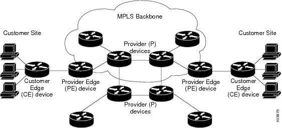
An MPLS Layer 3 VPN consists of a set of sites that are interconnected by an MPLS provider core network. At each customer site, one or more customer edge (CE) routers or Layer 2 switches attach to one or more provider edge (PE) routers.

This section includes the following topics:

MPLS Layer 3 VPN Definition

MPLS-based Layer 3 VPNs are based on a peer model that enables the provider and the customer to exchange Layer 3 routing information. The provider relays the data between the customer sites without direct customer involvement.

When you add a new site to an MPLS Layer 3 VPN, you must update the provider edge router that provides services to the customer site.

MPLS Layer 3 VPNs include the following components:

  • Provider (P) router—A router in the core of the provider network. P routers run MPLS switching and do not attach VPN labels (an MPLS label in each route assigned by the PE router) to routed packets. P routers forward packets based on the Label Distribution Protocol (LDP).
  • Resource Reservation Protocol (RSVP) traffic engineering (TE)— A protocol that assigns a label to the egress PE router.
  • Provider edge (PE) router—A router that attaches the VPN label to incoming packets that are based on the interface or subinterface on which they are received. A PE router attaches directly to a CE router.
  • Customer edge (CE) router—An edge router on the network of the provider that connects to the PE router on the network. A CE router must interface with a PE router.

Figure 22-1 shows a basic MPLS Layer 3 VPN.

Figure 22-1 Basic MPLS Layer 3 VPN Terminology


How an MPLS Layer 3 VPN Works

MPLS Layer 3 VPN functionality is enabled at the edge of an MPLS network. The PE router performs the following tasks:

  • Exchanges routing updates with the CE router
  • Translates the CE routing information into VPN routes
  • Exchanges Layer 3 VPN routes with other PE routers through the Multiprotocol Border Gateway Protocol (MP-BGP)

How VRF Tables Work in an MPLS Layer 3 VPN

Each Layer 3 VPN is associated with one or more virtual routing and forwarding (VRF) instance. A VRF defines the VPN membership of a customer site that is attached to a PE router. A VRF consists of the following components:

  • An IP routing table
  • A set of interfaces that use the forwarding table
  • A set of rules and routing protocol parameters that control the information that is included in the routing table

A one-to-one relationship does not necessarily exist between customer sites and VPNs. A site can be a member of multiple VPNs. Typically, a CE router at a site can associate with only one VRF. The VRF of the CE router contains all the routes that are available to the site from the VPNs of which the VRF is a member.

Packet forwarding information is stored in the IP routing table for each VRF. A separate set of routing tables is maintained for each VRF. These tables prevent information from being forwarded outside a VPN and also prevent packets that are outside a VPN from being forwarded to a router within the VPN.

VPN Route Distribution and Route Targets

The distribution of VPN routing information is controlled through VPN route targets that are implemented by BGP extended communities. VPN routing information is distributed as follows:

  • When a VPN route that is learned from a CE router is injected into BGP, a list of VPN route target extended community attributes is associated with the VPN route. Typically, the list of route target community extended values is set from an export list of route targets associated with the VRF from which the route was learned.
  • An import list of route target extended communities is associated with each VRF. The import list defines route target extended community attributes that a route must have in order for the route to be imported into the VRF. For example, if the import list for a particular VRF includes route target extended communities A, B, and C, then any VPN route that carries any of those route target extended communities—A, B, or C—is imported into the VRF.

Route Leaking and Importing Routes from the Default VRF

You can import IP prefixes from the global routing table (the default VRF) into any other VRF by using an import policy. The VRF import policy uses a route map to specify the prefixes to be imported into a VRF. The policy can import IPv4 and IPv6 unicast prefixes.


Note Routes in the BGP default VRF can be imported directly. Any other routes in the global routing table should be redistributed into BGP first.


IP prefixes are defined as match criteria for the import route map through standard route policy filtering mechanisms. For example, you can create an IP prefix list or an as-path filter to define an IP prefix or IP prefix range and use that prefix list or as-path filter in a match clause for the route map. Prefixes that pass through the route map are imported into the specified VRF using the import policy. IP prefixes that are imported into a VRF through this import policy cannot be reimported into another VPN VRF.

The maximum number of prefixes that can be imported from the default VRF is controlled by a limit that you configure.

VRF Route Table Limits

You can configure a limit to the number of routes that are accepted and installed into a VRF routing table to prevent overloading the PE router. This limit applies only to dynamic routing protocols and not to static or connected routes. Alternately, when you use eBGP as the PE-CE protocol, you can configure a per-neighbor maximum prefix limit.

VPN ID and Route Distinguisher

You use an MPLS VPN ID to identify a VPN but not to control route distribution or routing updates. You assign the same VPN ID to all routers in the provider network that service the VPN. The VPN ID format is specified in RFC 2685.

The route distinguisher (RD) is an eight-byte value that is combined with the IPv4 or IPv6 prefix learned by the PE router to create a globally unique address.

6VPE

The IPv6 PE router over MPLS Virtual Private Network (6VPE) feature is an extension of Layer 3 VPNs that support VPN connectivity for IPv6 sites over an MPLS/IPv4 provider core network. The VPN-IPv6 address is formed by adding an 8-byte RD to a 16-byte IPv6 address, which results in a 24-byte VPN-IPv6 address. 6VPE uses VRF tables to assign the forwarding information at the PE and uses the IPv6 address family. BGP supports the VPN-IPv6 address family. This address family supports both per-prefix and per-VRF label allocation modes.

6VPE prepends the IPv4 next-hop address with ::FFFF: to create the IPv4-mapped IPv6 address for the next hop that is advertised.


Note MPLS Layer 3 load balancing is supported for 6VPE but is not supported with per-VRF label allocation.


VPN IPv4 sites often use private addressing for their addressing plan. These addresses do not need to be registered, and they are not routable on the public network. Whenever a host within a private site needs to access a public domain, it goes through a device that finds a public address on its behalf, such as a network address translator or an application proxy.

Due to the larger address space available with IPv6, the easiest approach to IPv6 addressing is to use IPv6 global addresses for the private addressing plan. Another approach is to use unique local addresses (ULAs). ULAs are easy to filter at site boundaries based on their local scope. ULAs are Internet service provider (ISP)-independent and can be used for communications inside a site without any permanent or intermittent Internet connectivity.

In 6VPE, ULAs are treated as regular global addresses. The router configuration filters ULA prefixes to prevent them from appearing in the public domain. Link-local addresses on the peer are not announced by BGP (IPv6 or IPv6 VPN) speakers.

A host within a private site that needs to access a public domain can do so through an IPv6 application proxy (such as a web proxy for accessing web pages), which accesses the public resource, on behalf of the host, with a global routable address, or the host can use a public address of its own. In the latter case, if you have deployed ULAs, the IPv6 host also is configured with a routable global address. A source address selection algorithm is used to select one or the other, based on the destination address.

BGP PIC

BGP Prefix Independent Convergence (PIC) achieves subsecond convergence in the forwarding plane for BGP IP and Layer 3 VPN routes in various cases of BGP next-hop network reachability failures. BGP PIC has two categories: PIC Core and PIC Edge. PIC Core ensures fast convergence for BGP routes when there is a link or node failure in the core that causes a change in the IGP reachability to a remote BGP next-hop address. PIC Edge ensures fast convergence to a precomputed BGP backup path when an external (eBGP) edge link or an external neighbor node fails.

IPv4, VPNv4, 6PE, and VPNv6 (6VPE) support PIC Core with the following constraints:

  • For both IP and MPLS core, convergence for Internet routes is prefix-independent on the order of BGP next hops.
  • With per-VRF label allocation, VPN route convergence is also prefix-independent on the order of BGP next hops. That is, when a path to a remote PE changes, convergence is determined by the number of VRFs on that PE.
  • With per-prefix label allocation, route convergence is not prefix-independent. Convergence moves to the order of VPN routes that are advertised by a remote PE if a failure or change occurs in the reachability to that PE.

Note PIC edge is not supported.


BGP Distribution of VPN Routing Information

A PE router can learn an IP prefix from the following sources:

  • A CE router by static configuration
  • A directly connected network
  • A BGP session with the CE router
  • A routing protocol exchange with the CE router

After the PE router learns the IP prefix, the PE can conditionally export the prefix into a VPN prefix by combining it with an 8-byte route distinguisher. The generated prefix is a member of the VPN-IPv4 or the VPN-IPv6 address family. It uniquely identifies the customer address, even if the customer site is using globally nonunique (unregistered private) IP addresses. You configure the route distinguisher that generates the VPN-IPv4 or VPN-IPv6 prefix on the VRF on the PE router.

BGP distributes reachability information for VPN prefixes for each VPN. BGP communication takes place at two levels:

  • Within an autonomous system using interior BGP (iBGP)
  • Between autonomous systems using external BGP (eBGP)

PE-PE or PE-RR (route reflector) sessions are iBGP sessions, and PE-CE sessions are eBGP sessions. BGP propagates reachability information for VPN-IPv4 and VPN-IPv6 prefixes among PE routers by using BGP multiprotocol extensions (see RFC 2283, Multiprotocol Extensions for BGP-4 ). The BGP multiprotocol extensions define support for address families other than IPv4. When you use the extensions, you ensure that the routes for a given VPN are learned only by other members of that VPN. This process enables members of the VPN to communicate with each other.

In an Enhanced Interior Gateway Routing Protocol (EIGRP) PE-CE environment, when an EIGRP internal route is redistributed into BGP by one PE, then back into EIGRP by another PE, the originating router ID for the route is set to the router ID of the second PE. This process replaces the original internal router ID.


Note The BGP minimum route advertisement interval (MRAI) value for all iBGP and eBGP sessions is zero and is not configurable.


BGP Next-Hop Address Tracking

See the “Configuring Advanced BGP” chapter of the Cisco Nexus 7000 Series NX-OS Unicast Routing Configuration Guide for information.

MPLS Forwarding

Based on routing information in the VRF IP routing table, the router forwards packets to their destination using MPLS.

A PE router binds a label to each customer prefix that is learned from a CE router and includes the label in the network reachability information for the prefix that it advertises to other PE routers. When a PE router forwards a packet that it received from a CE router across the provider network, it labels the packet with the label learned from the destination PE router. When the destination PE router receives the labeled packet, it removes the label and uses it to direct the packet to the correct CE router. Label forwarding across the provider backbone is based on either dynamic label switching or traffic engineered paths. A customer data packet carries two levels of labels when it traverses the backbone:
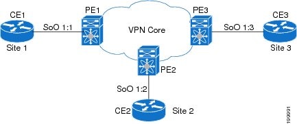
  • The top label directs the packet to the correct PE router.
  • The second label indicates how that PE router should forward the packet to the CE router.

Site of Origin

The site of origin prevents routing loops when you have a multihomed VPN site. Routes learned from the same site are tagged with the same site-of-origin value that is configured at the PE on all the PE-CE links to the same site. Routes with a particular site-of-origin value are never readvertised back to a CE with the same site-of-origin value configured at the PE-CE link. This process prevents a CE router from relearning routes that originated from the same site. BGP and EIGRP use site of origin to prevent loops.

You can override the autonomous system number (ASN) of a site with the ASN of the provider. This feature is often used with the site of origin to identify the site where a route originated and prevent routing loops between routers within a VPN.

Site of Origin and EIGRP

When EIGRP is used as the PE-CE routing protocol, EIGRP uses BGP extended communities to carry the EIGRP vector metric, AS number, and other information to recreate the EIGRP internal routes with the original attributes across the VPN cloud. EIGRP external routes or routes from a different autonomous system are recreated as external routes.

EIGRP uses site of origin to prevent routing loops when you have a multihomed VPN site. You must configure the site of origin for EIGRP-based PE routes that are learned from the CE. We recommend you use the site of origin for CE routers for better performance.

You might want to disable the BGP best path cost community option in a multihomed VPN site and use the internal routes to fully utilize all PE-CE links. The default behavior is that only one PE-CE link is used and the other PE-CE links serve as backup links.

OSPF Sham Link

Although Open Shortest Path First (OSPF) PE-CE connections assume that the only path between two client sites is across the MPLS Layer 3 VPN backbone, backdoor paths between VPN sites might exist. If these sites belong to the same OSPF area, the router always chooses the path over a backdoor link because OSPF prefers intra-area paths to interarea paths. (PE routers advertise OSPF routes that they learned over the VPN backbone as interarea paths.)

To reestablish the desired path selection over the MPLS Layer 3 VPN backbone, you must create an additional OSPF intra-area (logical) link between ingress and egress VRFs on the relevant PE routers. This link is called a sham link. A sham link is required between any two VPN sites that belong to the same OSPF area and share an OSPF backdoor link. If no backdoor link exists between the sites, no sham link is required. When a sham link is configured between PE routers, the PEs can populate the VRF routing table with the OSPF routes learned over the sham link. Because OSPF sees the sham link as an intra-area link between PE routers, an OSPF creates an adjacency and triggers a database exchange (for the particular OSPF process) across the link. The PE router can then flood LSAs between sites from across the MPLS VPN backbone and create intra-area connectivity.

OSPF LSA Throttling

OSPF LSA throttling is enabled by default and allows faster OSPF convergence (in milliseconds). You can control the generation (sending) of LSAs, control the receiving interval, and provide a dynamic mechanism to slow down the frequency of LSA updates in OSPF during times of network instability.

The first LSA is always generated immediately upon an OSPF topology change, and the next LSA generated is controlled by a configured minimum start interval. The subsequent LSAs generated for the same LSA are rate limited until the configured maximum interval is reached. The same LSA is defined as an LSA instance that contains the same LSA ID number, LSA type, and advertising router ID.

If an instance of the same LSA arrives sooner than the configured receive interval, the LSA is dropped.


Note We recommend that you use an arrival interval that is less than or equal to the hold-time interval.


Components of MPLS Layer 3 VPNs

An MPLS-based Layer 3 VPN network has three components:

1. VPN route target communities—A VPN route target community is a list of all members of a Layer 3 VPN community. You must configure the VPN route targets for each Layer 3 VPN community member.

2. Multiprotocol BGP peering of VPN community PE routers—Multiprotocol BGP propagates VRF reachability information to all members of a VPN community. You must configure Multiprotocol BGP peering in all PE routers within a VPN community.

3. MPLS forwarding—MPLS transports all traffic between all VPN community members across a VPN enterprise or service provider network.

A one-to-one relationship does not necessarily exist between customer sites and VPNs. A site can be a member of multiple VPNs. However, a site can associate with only one VRF. A customer-site VRF contains all the routes that are available to the site from the VPNs of which it is a member.

High Availability and ISSU for MPLS Layer 3 VPNs

The Cisco NX-OS architecture and high availability (HA) infrastructure enables feature components to restart and resume operations transparently to other services on the device and on neighboring devices. This process allows for continuous operation and minimal data loss during planned software changes and unplanned software failures.

MPLS 6PE/6VPE supports these Cisco NX-OS HA features:

  • Nonstop forwarding (NSF)
  • Stateful HA

MPLS 6PE/6VPE supports these Cisco NX-OS HA technologies to allow NSF and stateful HA:

  • Stateful process restart
  • Stateful switchover (SSO)
  • In-Service Software Upgrade (ISSU)

MPLS Layer 3 VPN supports these Cisco NX-OS HA technologies:

  • NSF of Layer 2 traffic
  • Graceful (stateless) restart of Layer 3 processes
  • SSO
  • ISSU

Note NSF requires that graceful restart is enabled in BGP and LDP.


BGP has graceful restart extensions for labels that are received from peers and recovers the local labels that are allocated for VPN routes across a BGP restart or for a supervisor switchover. BGP does not support stateful restart but on a supervisor switchover, BGP does a stateless recovery through graceful restart procedures. Cisco NX-OS forces a supervisor switchover if the BGP process fails to restart after two attempts.

The PE-CE protocols are either stateful or use graceful restart for routes that are learned from locally connected CEs. The forwarding plane continues to switch packets both for IPv4 and IPv6 routes as well as MPLS labels during any component restart or supervisor switchover.

Hub-and-Spoke Topology

A hub-and-spoke topology prevents local connectivity between subscribers at the spoke provider edge (PE) routers and ensures that a hub site provides subscriber connectivity. Any sites that connect to the same PE router must forward intersite traffic using the hub site. This topology ensures that the routing at the spoke sites moves from the access-side interface to the network-side interface or from the network-side interface to the access-side interface but never from the access-side interface to the access-side interface. A hub-and-spoke topology allows you to maintain access restrictions between sites.

A hub-and-spoke topology prevents situations where the PE router locally switches the spokes without passing the traffic through the hub site. This topology prevents subscribers from directly connecting to each other.

A hub-and-spoke topology does not require one VRF for each spoke.

Figure 22-2 shows a sample hub-and-spoke topology.

Figure 22-2 Hub-and-Spoke Topology


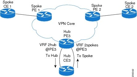
As shown in the figure, a hub-and-spoke topology is typically set up with a hub PE that is configured with two VRFs:

  • VRF 2hub with a dedicated link connected to the hub customer edge (CE).
  • VRF 2spokes with another dedicated link connected to the hub CE.

Interior Gateway Protocol (IGP) or external BGP (eBGP) sessions are usually set up through the hub PE-CE links. The VRF 2hub imports all the exported route targets from all the spoke PEs. The hub CE learns all routes from the spoke sites and readvertises them back to the VRF 2spoke of the hub PE. The VRF 2spoke exports all these routes to the spoke PEs.

If you use eBGP between the hub PE and hub CE, you must allow duplicate autonomous system (AS) numbers in the path which is normally prohibited. You can configure the router to allow this duplicate AS number at the neighbor of VRF 2spokes of the hub PE and also for VPN address family neighbors at all the spoke PEs. In addition, you must disable the peer AS number check at the hub CE when distributing routes to the neighbor at VRF 2spokes of the hub PE.

Reverse Path Forwarding Check

The unicast Reverse Path Forwarding (uRPF) check ensures that an IP packet that enters a router uses the correct inbound interface. A hub-and-spoke configuration supports uRPF checks on the spoke-side interfaces. Because different virtual routing and forwarding instances (VRFs) are used for downstream and upstream forwarding, the uRPF mechanism ensures that source address checks occur in the downstream VRF.

OSPF Sham-Link Support for MPLS VPN

In a Multiprotocol Label Switching (MPLS) VPN configuration, you can use the Open Shortest Path First (OSPF) protocol to connect customer edge (CE) devices to service provider edge (PE) devices in the VPN backbone. Many customers run OSPF as their intrasite routing protocol, subscribe to a VPN service, and want to exchange routing information between their sites using OSPF (during migration or on a permanent basis) over an MPLS VPN backbone.

The benefits of the OSPF sham-link support for MPLS VPN are as follows:

  • Client site connection across the MPLS VPN Backbone—A sham link ensures that OSPF client sites that share a backdoor link can communicate over the MPLS VPN backbone and participate in VPN services.
  • Flexible routing in an MPLS VPN configuration—In an MPLS VPN configuration, the OSPF cost tha is configured with a sham link allows you to decide if OSPF client site traffic is routed over a backdoor link or through the VPN backbone.

The figure below shows an example of how VPN client sites that run OSPF can connect over an MPLS VPN backbone.


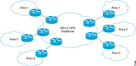
When you use OSPF to connect PE and CE devices, all routing information learned from a VPN site is placed in the VPN routing and forwarding (VRF) instance that is associated with the incoming interface. The PE devices that attach to the VPN use the Border Gateway Protocol (BGP) to distribute VPN routes to each other. A CE device can learn the routes to other sites in the VPN by peering with its attached PE device. The MPLS VPN super backbone provides an additional level of routing hierarchy to interconnect the VPN sites that are running OSPF.

When OSPF routes are propagated over the MPLS VPN backbone, additional information about the prefix in the form of BGP extended communities (route type, domain ID extended communities) is appended to the BGP update. This community information is used by the receiving PE device to decide the type of link-state advertisement (LSA) to be generated when the BGP route is redistributed to the OSPF PE-CE process. In this way, internal OSPF routes that belong to the same VPN and are advertised over the VPN backbone are seen as interarea routes on the remote sites.

Correcting OSPF Backdoor Routing

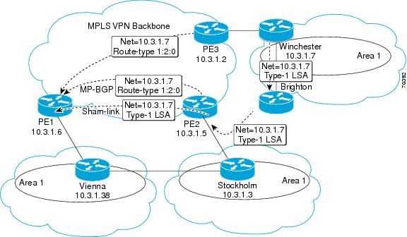
Although the Open Shortest Path First (OSPF) provider edge-to-customer edge (PE-CE) connections assume that the only path between two client sites is across the Multiprotocol Layer Switching (MPLS) VPN backbone, backdoor paths between VPN sites (shown in gray in the figure below) might exist. If these sites belong to the same OSPF area, the device chooses a path over a backdoor link because OSPF prefers intra-area paths to interarea paths. (PE devices advertise OSPF routes learned over the VPN backbone as interarea paths.) Therefore, routing is performed based on policy.


For example, the figure above shows three client sites, each with backdoor links. Because each site runs OSPF within the same Area 1 configuration, all routing between the three sites follows the intra-area path across the backdoor links, rather than over the MPLS VPN backbone.

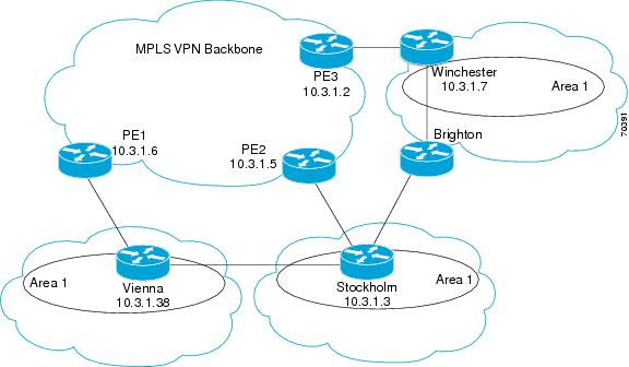
The following example shows Border Gateway Protocol (BGP) routing table entries for the prefix 10.3.1.7/32 in the PE-1 device in the figure above. This prefix is the loopback interface of the Winchester CE device. As shown in bold in this example, the loopback interface is learned through BGP from PE-2 and PE-3. It is also generated through redistribution into BGP on PE-1.

PE-1# show ip bgp vpnv4 all 10.3.1.7
BGP routing table entry for 100:251:10.3.1.7/32, version 58
Paths: (3 available, best #2)
Advertised to non peer-group peers:
10.3.1.2 10.3.1.5
Local
10.3.1.5 (metric 30) from 10.3.1.5 (10.3.1.5)
Origin incomplete, metric 22, localpref 100, valid, internal
Extended Community: RT:1:793 OSPF DOMAIN ID:0.0.0.100 OSPF
RT:1:2:0 OSPF 2
Local
10.2.1.38 from 0.0.0.0 (10.3.1.6)
Origin incomplete, metric 86, localpref 100, weight 32768,
valid, sourced, best
Extended Community: RT:1:793 OSPF DOMAIN ID:0.0.0.100 OSPF
RT:1:2:0 OSPF 2
Local
10.3.1.2 (metric 30) from 10.3.1.2 (10.3.1.2)
Origin incomplete, metric 11, localpref 100, valid, internal
Extended Community: RT:1:793 OSPF DOMAIN ID:0.0.0.100 OSPF
RT:1:2:0 OSPF 2
 

Within BGP, the locally generated route (10.2.1.38) is considered to be the best route. However, as shown in bold in the next example, the VRF routing table shows that the selected path is learned through OSPF with a next hop of 10.2.1.38, shown in the figure as the Vienna CE device.

PE-1# show ip route vrf ospf 10.3.1.7
Routing entry for 10.3.1.7/32
Known via "ospf 100", distance 110, metric 86, type intra area
Redistributing via bgp 215
Advertised by bgp 215
Last update from 10.2.1.38 on Serial0/0/0, 00:00:17 ago
Routing Descriptor Blocks:
* 10.2.1.38
, from 10.3.1.7, 00:00:17 ago, via Serial0/0/0
Route metric is 86, traffic share count is 1
 

This path is selected for the following reasons:

  • The OSPF intra-area path is preferred over the interarea path (over the MPLS VPN backbone) that is generated by the PE-1 device.
  • OSPF has a lower administrative distance (AD) than internal BGP (BGP running between devices in the same autonomous system).

If the backdoor links between sites are used only for backup and do not participate in the VPN service, the default route selection shown in the preceding example is not acceptable. To reestablish the desired path selection over the MPLS VPN backbone, you must create an additional OSPF intra-area (logical) link between ingress and egress VRFs on the relevant PE devices. This link is called a sham link.

A sham link is required between any two VPN sites that belong to the same OSPF area and share an OSPF backdoor link. If no backdoor link exists between the sites, no sham link is required.

The figure below shows a sample sham link between PE-1 and PE-2. A cost is configured with each sham link and is used to decide whether traffic is sent over the backdoor path or the sham-link path. When a sham link is configured between PE devices, the PEs can populate the VRF routing table with the OSPF routes learned over the sham link.


Because the sham link is seen as an intra-area link between PE devices, an OSPF adjacency is created and database exchange (for the particular OSPF process) occurs across the link. The PE device can then flood LSAs between sites from across the MPLS VPN backbone. As a result, intra-area connectivity is created.

Licensing Requirements for MPLS Layer 3 VPNs


Product
License Requirement

Cisco NX-OS

MPLS Layer 3 VPNs require an MPLS license. For a complete explanation of the Cisco NX-OS licensing scheme and how to obtain and apply licenses, see the Cisco NX-OS Licensing Guide.

Note VRF lite does not require an MPLS license for route leaking.

Prerequisites for MPLS Layer 3 VPNs

MPLS Layer 3 VPNs has the following prerequisites:

  • Ensure that you have configured MPLS and Label Distribution Protocol (LDP) or Resource Reservation Protocol (RSVP) Traffic Engineering (TE) in your network. All routers in the core, including the PE routers, must be able to support MPLS forwarding.
  • Ensure that you have installed the correct license for MPLS and any other features you will be using with MPLS.

Guidelines and Limitations for MPLS Layer 3 VPNs

MPLS Layer 3 VPNs have the following configuration guidelines and limitations:

  • MPLS Layer 3 VPNs support the following CE-PE routing protocols:

– BGP (IPv4 and IPv6)

– Enhanced Interior Gateway Protocol (EIGRP) (IPv4)

– Open Shortest Path First (OSPFv2)

– Routing Information Protocol (RIPv2)


Note Cisco NX-OS supports static routes (IPv4 and IPv6) for PE-CE routing.


  • Set statements in an import route map are ignored.
  • The BGP minimum route advertisement interval (MRAI) value for all iBGP and eBGP sessions is zero and is not configurable.
  • In a high scale setup with many BGP routes getting redistributed into EIGRP, modify the EIGRP signal timer to ensure that the EIGRP convergence time is higher than the BGP convergence time. This process allows all the BGP routes to be redistributed into EIGRP, before EIGRP signals convergence.
  • For Cisco NX-OS releases before Cisco NX-OS Release 5.2(5), the EIGRP site of origin requires an MPLS license and he MPLS Layer 3 VPN feature is enabled. Beginning with Cisco NX-OS Release 5.2(5), the EIGRP site of origin feature does not require an MPLS license.

OSPF sham-link support for MPLS VPN has the following guideline and limitation:

  • When OSPF is used as a protocol between PE and CE devices, the OSPF metric is preserved when routes are advertised over the VPN backbone. The metric is used on the remote PE devices to select the correct route. Do not modify the metric value when OSPF is redistributed to BGP and when BGP is redistributed to OSPF. If you modify the metric value, routing loops might occur.

Default Settings for MPLS Layer 3 VPNs

Table 22-1 lists the default settings for MPLS Layer 3 VPN parameters.


Table 22-1 Default MPLS Layer 3 VPN Parameters

Parameters
Default

L3VPN feature

Disabled

L3VPN SNMP notifications

Disabled

allowas-in (for a hub-and-spoke topology)

0

disable-peer-as-check (for a hub-and-spoke topology)

Disabled

Configuring MPLS Layer 3 VPNs

This section includes the following topics:

Assessing the Needs of MPLS Layer 3 VPN Customers

You can identify the core network topology so that it can best serve MPLS Layer 3 VPN customers.


Step 1 Identify the size of the network:

– Identify the following to determine the number of routers and ports you need:

– How many customers do you need to support?

– How many VPNs are needed per customer?

– How many virtual routing and forwarding instances are there for each VPN?

Step 2 Determine which routing protocols you need in the core network.

Step 3 Determine if you need MPLS VPN high availability support.


Note MPLS VPN nonstop forwarding and graceful restart are supported on select routers and Cisco NX-OS releases. You need to make sure that graceful restart for BGP and LDP is enabled.


Step 4 Configure the routing protocols in the core network.


Note See the Cisco Nexus 7000 Series NX-OS Unicast Routing Configuration Guide for configuration steps.


Step 5 Determine if you need BGP load sharing and redundant paths in the MPLS Layer 3 VPN core.


Note See the “Configuring MPLS Layer 3 VPN Load Balancing” section for more information.


Configuring MPLS in the Core

To enable MPLS on all routers in the core, you must configure a label distribution protocol. You can use either of the following as a label distribution protocol:

  • MPLS Label Distribution Protocol (LDP).
  • MPLS Traffic Engineering Resource Reservation Protocol (RSVP).

Configuring Multiprotocol BGP on the PE Routers and Route Reflectors

You can configure multiprotocol BGP connectivity on the PE routers and route reflectors.

Prerequisites

  • Ensure that you are in the correct virtual device context (VDC) (or use the switchto vdc command).
  • Ensure that graceful restart is enabled on all routers for BGP and LDP.

DETAILED STEPS


Command
Purpose

Step 1

configure terminal


Example:

switch# configure terminal

switch(config)#

Enters global configuration mode.

Step 2

feature bgp


Example:

switch(config)# feature bgp

Enables the BGP feature.

Step 3

feature-set mpls


Example:

switch(config)# feature-set mpls

Enables the MPLS feature-set.

Step 4

feature mpls l3vpn


Example:

switch(config)# feature mpls l3vpn

Enables the MPLS Layer 3 VPN feature.

Step 5

router bgp as - number


Example:

switch(config)# router bgp 1.1

switch(config-router)#

Configures a BGP routing process and enters router configuration mode.

The as-number argument indicates the number of an autonomous system that identifies the router to other BGP routers and tags the routing information passed along. The AS number can be a 16-bit integer or a 32-bit integer in the form of a higher 16-bit decimal number and a lower 16-bit decimal number in xx.xx format.

Step 6

router-id ip-address


Example:

switch(config-router)# router-id 192.0.2.255


(Optional) Configures the BGP router ID. This IP address identifies this BGP speaker. This command triggers an automatic notification and session reset for the BGP neighbor sessions.

Step 7

neighbor ip-address remote-as as-number


Example:

switch(config-router)# neighbor 209.165.201.1 remote-as 1.1

switch(config-router-neighbor)#

Adds an entry to the iBGP neighbor table. The ip-address argument specifies the IP address of the neighbor in dotted decimal notation.

Step 8

address-family { vpnv4 | vpnv6 } unicast


Example:

switch(config-router-neighbor)# address-family vpnv4 unicast

switch(config-router-neighbor-af)#

Enters address family configuration mode for configuring routing sessions, such as BGP, that use standard VPNv4 or VPNv6 address prefixes.

Step 9

send-community extended


Example:

switch(config-router-neighbor-af)# send-community extended

Specifies that a communities attribute should be sent to a BGP neighbor.

Step 10

show bgp { vpnv4 | vpnv6 } unicast neighbors


Example:

switch(config-router-neighbor-af)# show bgp vpnv4 unicast neighbors

(Optional) Displays information about BGP neighbors.

Step 11

copy running-config startup-config


Example:

switch(config-router-neighbor-af)# copy running-config startup-config

(Optional) Copies the running configuration to the startup configuration.

Defining VRFs on the PE Routers to Enable Customer Connectivity

You must create VRFs on the PE routers to enable customer connectivity. You configure route targets to control which IP prefixes are imported into the customer VPN site and which IP prefixes are exported to the BGP network. You can optionally use an import or export route map to provide more fine-grained control over the IP prefixes that are imported into the customer VPN site or exported out of the VPN site. You can use a route map to filter routes that are eligible for import or export in a VRF, based on the route target extended community attributes of the route. The route map might, for example, deny access to selected routes from a community that is on the import route target list.


Note If you are using import maps, you must configure an import statement in order for the import map to take effect. Similarly, you must configure an export statement in order for the export map to take effect. Beginning with Cisco NX-OS Release 5.2(5), however, an export statement is not required in order for the export map to take effect.


Note Beginning with Cisco NX-OS Releases 5.2(7) and 6.1(2), import maps support matching and setting on standard and extended communities. In earlier releases, import maps do not support matching and setting on standard and extended communities. Beginning with Cisco NX-OS Release 5.2(1), export maps support matching and setting on standard and extended communities.


Prerequisites

Ensure that you are in the correct VDC (or use the switchto vdc command).

SUMMARY STEPS

1. configure terminal

2. feature- s et mpls

3. feature mpls l3vpn

4. vrf context vrf-name

5. rd route-distinguisher

6. address-family { ipv4 | ipv6 } unicast

7. route-target { import | export } route-target-ext-community

8. (Optional) maximum routes max-prefix [ threshold value] [ reinstall]

9. (Optional) import [ vrf default max-prefix ] map route-map

10. (Optional) show vrf vrf-name

11. (Optional) copy running-config startup-config

DETAILED STEPS


Command
Purpose

Step 1

configure terminal


Example:

switch# configure terminal

switch(config)#

Enters global configuration mode.

Step 2

feature-set mpls


Example:

switch(config)# feature-set mpls

Enables the MPLS feature-set.

Step 3

feature mpls l3vpn


Example:

switch(config)# feature mpls l3vpn

Enables the MPLS Layer 3 VPN feature.

Step 4

vrf context vrf-name


Example:

switch(config)# vrf context vpn1

switch(config-vrf)#

Defines the VPN routing instance by assigning a VRF name and enters VRF configuration mode. The vrf-name argument is any case-sensitive, alphanumeric string up to 32 characters.

Step 5

rd route-distinguisher


Example:

switch(config-vrf)# rd 1.2:1

Configures the route distinguisher. The route-distinguisher argument adds an 8-byte value to an IPv4 prefix to create a VPN IPv4 prefix. You can enter an RD in either of these formats:

  • 16-bit or 32-bit AS number: your 32-bit number, for example, 1.2:3
  • 32-bit IP address: your 16-bit number, for example, 192.0.2.1:1

Step 6

address-family { ipv4 | ipv6 } unicast


Example:

switch(config-vrf)# address-family ipv4 unicast

switch(config-vrf-af-ipv4)#

Specifies the IPv4 address family type and enters address family configuration mode.

Step 7

route-target { import | export } route-target-ext-community


Example:

switch(config-vrf-af-ipv4)# route-target import 1.0:1

Specifies a route-target extended community for a VRF as follows:

  • The import keyword imports routing information from the target VPN extended community.
  • The export keyword exports routing information to the target VPN extended community.
  • The route-target-ext-community argument adds the route-target extended community attributes to the VRF's list of import or export route-target extended communities. You can enter the route-target-ext-community argument in either of these formats:

– 16-bit or 32-bit AS number: your 32-bit number, for example, 1.2:3

– 32-bit IP address: your 16-bit number, for example, 192.0.2.1:1

Step 8

maximum routes max-routes [ threshold value] [ reinstall ]


Example:

switch(config-vrf-af-ipv4)# maximum routes 10000

(Optional) Configures the maximum number of routes that can be stored in the VRF route table. The max-routes range is from 1 to 4294967295. The threshold value range is from 1 to 100.

Step 9

import [ vrf default max-prefix ] map route-map


Example:

switch(config-vrf-af-ipv4)# import vrf default map vpn1-route-map

(Optional) Configures an import policy for a VRF to import prefixes from the default VRF as follows:

  • The max-prefix range is from 1 to 2147483647. The default is 1000 prefixes.
  • The route-map argument specifies the route map to be used as an import route map for the VRF and can be any case-sensitive, alphanumeric string up to 63 characters.

Step 10

show vrf vrf-name


Example:

switch(config-vrf-af-ipv4)# show vrf vpn1

(Optional) Displays information about a VRF. The vrf-name argument is any case-sensitive, alphanumeric string up to 32 characters.

Step 11

copy running-config startup-config


Example:

switch(config-vrf-af)# copy running-config startup-config

(Optional) Copies the running configuration to the startup configuration.

Configuring VRF Interfaces on PE Routers for Each VPN Customer

You can associate a virtual routing and forwarding instance (VRF) with an interface or subinterface on the PE routers.

Prerequisites

Ensure that you are in the correct VDC (or use the switchto vdc command).

SUMMARY STEPS

1. configure terminal

2. interface type number

3. vrf member vrf-name

4. (Optional) show vrf vrf-name interface

5. (Optional) copy running-config startup-config

DETAILED STEPS

 
Command
Purpose

Step 1

configure terminal


Example:

switch# configure terminal

switch(config)#

Enters global configuration mode.

Step 2

interface type number


Example:

switch(config)# interface Ethernet 5/0

switch(config-if)#

Specifies the interface to configure and enters interface configuration mode as follows:

  • The type argument specifies the type of interface to be configured.
  • The number argument specifies the port, connector, or interface card number.

Step 3

vrf member vrf-name


Example:

switch(config-if)# vrf member vpn1

Associates a VRF with the specified interface or subinterface. The vrf-name argument is the name assigned to a VRF.

Step 4

show vrf vrf-name interface


Example:

switch(config-if)# show vrf vpn1 interface

(Optional) Displays information about interfaces associated with a VRF. The vrf-name argument is any case-sensitive alphanumeric string up to 32 characters.

Step 5

copy running-config startup-config


Example:

switch(config-if)# copy running-config startup-config

(Optional) Copies the running configuration to the startup configuration.

Configuring Static or Directly Connected Routes Between the PE and CE Routers

You can configure the PE router for PE-to-CE routing sessions that use static routes.

Prerequisites

Ensure that you are in the correct VDC (or use the switchto vdc command).

SUMMARY STEPS

1. configure terminal

2. vrf context vrf-name

3. { ip | ipv6 } route prefix/mask nexthop

4. address-family { ipv4 | ipv6 } unicast

5. feature bgp

6. router bgp as - number

7. vrf vrf-name

8. address-family { ipv4 | ipv6 } unicast

9. redistribute static route-map map-tag

10. redistribute direct route-map map-tag

11. (Optional) show { ipv4 | ipv6 } route static vrf vrf-name

12. (Optional) copy running-config startup-config

DETAILED STEPS


Command
Purpose

Step 1

configure terminal


Example:

switch# configure terminal

switch(config)#

Enters global configuration mode.

Step 2

vrf context vrf-name


Example:

switch(config)# vrf context vpn1

switch(config-vrf)#

Defines the VPN routing instance by assigning a VRF name and enters VRF configuration mode. The vrf-name argument is any case-sensitive, alphanumeric string up to 32 characters.

Step 3

{ ip | ipv6 } route prefix nexthop


Example:

switch(config-vrf)# ip route 192.0.2.1/28 ethernet 2/1

Defines static route parameters for every PE-to-CE session. The prefix and nexthop are as follows:

  • IPv4—in dotted decimal notation
  • IPv6—in hex format.

Step 4

address-family { ipv4 | ipv6 } unicast


Example:

switch(config-vrf)# address-family ipv4 unicast

switch(config-vrf-af)#

Specifies the IPv4 address family type and enters address family configuration mode.

Step 5

feature bgp


Example:

switch(config-vrf-af)# feature bgp

switch(config)#

Enables the BGP feature.

Step 6

router bgp as - number


Example:

switch(config)# router bgp 1.1

switch(config-router)#

Configures a BGP routing process and enters router configuration mode.

The as-number argument indicates the number of an autonomous system that identifies the router to other BGP routers and tags the routing information passed along. The AS number can be a 16-bit integer or a 32-bit integer in the form of a higher 16-bit decimal number and a lower 16-bit decimal number in xx.xx format.

Step 7

vrf vrf-name


Example:

switch(config-router)# vrf vpn1

switch(config--router-vrf)#

Associates the BGP process with a VRF.

The vrf-name argument is any case-sensitive, alphanumeric string up to 32 characters.

Step 8

address-family { ipv4 | ipv6 } unicast


Example:

switch(config-router-vrf)# address-family ipv4 unicast

switch(config-router-vrf-af)#

Specifies the address family type and enters address family configuration mode.

Step 9

redistribute static route-map map-name


Example:

switch(config-router-vrf-af)# redistribute static route-map StaticMap

Redistributes static routes into BGP.

The map-name can be any case-sensitive, alphanumeric string up to 63 characters.

Step 10

redistribute direct route-map map-name


Example:

switch(config-router-vrf-af)# redistribute direct route-map DirectMap

Redistributes directly connected routes into BGP.

The map-name can be any case-sensitive, alphanumeric string up to 63 characters.

Step 11

show { ipv4 | ipv6 } route vrf vrf-name


Example:

switch(config-router-vrf-af)# show ip ipv4 route vrf vpn1

(Optional) Displays information about routes.

The vrf-name argument is any case-sensitive, alphanumeric string up to 32 characters.

Step 12

copy running-config startup-config


Example:

switch(config-router-vrf-af)# copy running-config startup-config

(Optional) Copies the running configuration to the startup configuration.

Configuring BGP as the Routing Protocol Between the PE and CE Routers

You can use eBGP to configure the PE router for PE-to-CE routing sessions.

Prerequisites

Ensure that you are in the correct VDC (or use the switchto vdc command).

SUMMARY STEPS

1. configure terminal

2. feature bgp

3. router bgp as-number

4. vrf vrf-name

5. neighbor ip-address remote-as as-number

6. address-family { ipv4 | ipv6 } unicast

7. show bgp { ipv4 | ipv6 } unicast neighbors vrf vrf-name

8. copy running-config startup-config

DETAILED STEPS


Command
Purpose

Step 1

configure terminal


Example:

switch# configure terminal

switch(config)#

Enters global configuration mode.

Step 2

feature bgp


Example:

switch(config)# feature bgp

switch(config)#

Enables the BGP feature.

Step 3

router bgp as - number


Example:

switch(config)# router bgp 1.1

switch(config-router)#

Configures a BGP routing process and enters router configuration mode.

  • The as-number argument indicates the number of an autonomous system that identifies the router to other BGP routers and tags the routing information passed along. The AS number can be a 16-bit integer or a 32-bit integer in the form of a higher 16-bit decimal number and a lower 16-bit decimal number in xx.xx format.

Step 4

vrf vrf-name


Example:

switch(config-router)# vrf vpn1

switch(config--router-vrf)#

Associates the BGP process with a VRF.

The vrf-name argument is any case-sensitive, alphanumeric string up to 32 characters.

Step 5

neighbor ip-address remote-as as-number


Example:

switch(config-router-vrf)# neighbor 209.165.201.1 remote-as 1.2

switch(config-router-vrf-neighbor)#


Adds an entry to the eBGP neighbor table.

  • The ip-address argument specifies the IP address of the neighbor in dotted decimal notation.
  • The as-number argument specifies the autonomous system to which the neighbor belongs.

Step 6

address-family { ipv4 | ipv6 } unicast


Example:

switch(config-router-vrf-neighbor)# address-family ipv4 unicast

switch(config-router-vrf-neighbor-af)#

Enters address family configuration mode for configuring routing sessions, such as BGP, that use standard IPv4 or IPv6 address prefixes.

Step 7

show bgp { ipv4 | ipv6 } unicast neighbors vrf vrf-name


Example:

switch(config-router--vrf-neighbor-af)# show bgp ipv4 unicast neighbors vrf vpn1

(Optional) Displays information about BGP neighbors.

The vrf-name argument is any case-sensitive alphanumeric string up to 32 characters.

Step 8

copy running-config startup-config


Example:

switch(config-router-vrf-neighbor-af)# copy running-config startup-config

(Optional) Copies the running configuration to the startup configuration.

Configuring RIPv2 Between the PE and CE Routers

You can use RIP to configure the PE router for PE-to-CE routing sessions.

Prerequisites

Ensure that you are in the correct VDC (or use the switchto vdc command).

SUMMARY STEPS

1. configure terminal

2. feature rip

3. router rip instance-tag

4. vrf vrf-name

5. address-family ipv4 unicast

6. redistribute { bgp as | direct | { eigrp | ospf | rip } instance-tag | static } route-map map-name

7. (Optional) show ip rip vrf vrf-name

8. (Optional) copy running-config startup-config

DETAILED STEPS


Command
Purpose

Step 1

configure terminal


Example:

switch# configure terminal

switch(config)#

Enters global configuration mode.

Step 2

feature rip


Example:

switch(config)# feature rip

Enables the RIP feature.

Step 3

router rip instance-tag


Example:

switch(config)# router rip Test1

switch(config-router)#

Enables RIP and enters router configuration mode.

The instance-tag can be any case-sensitive, alphanumeric string up to 20 characters.

Step 4

vrf vrf-name


Example:

switch(config-router)# vrf vpn1

switch(config--router-vrf)#

Associates the RIP process with a VRF.

The vrf-name argument is any case-sensitive, alphanumeric string up to 32 characters.

Step 5

address-family ipv4 unicast


Example:

switch(config-router-vrf)# address-family ipv4 unicast

switch(config-router-vrf-af)#

Specifies the address family type and enters address family configuration mode.

Step 6

redistribute { bgp as | direct | { eigrp | ospf | rip } instance-tag | static } route-map map-name


Example:

switch(config-router-vrf-af)# redistribute bgp 1.0 route-map bagpipe

Redistributes routes from one routing domain into another routing domain.

The as number can be a 16-bit integer or a 32-bit integer in the form of a higher 16-bit decimal number and a lower 16-bit decimal number in xx.xx format. The instance-tag can be any case-sensitive alphanumeric string up to 20 characters.

Step 7

show ip rip vrf vrf-name


Example:

switch(config-router-vrf-af)# show ip rip vrf vpn1

(Optional) Displays information about RIP.

The vrf-name argument is any case-sensitive, alphanumeric string up to 32 characters.

Step 8

copy running-config startup-config


Example:

switch(config-router-af)# copy running-config startup-config

(Optional) Copies the running configuration to the startup configuration.

Configuring OSPF Between the PE and CE Routers

You can use OSPFv2 to configure the PE router for PE-to-CE routing sessions. You can optionally create an OSPF sham link if you have OSPF back door links that are not part of the MPLS network.

Prerequisites

Ensure that you are in the correct VDC (or use the switchto vdc command).

SUMMARY STEPS

1. configure terminal

2. feature ospf

3. router ospf instance-tag

4. vrf vrf-name

5. (Optional) area area-id sham-link source-address destination-address

6. address-family { ipv4 | ipv6 } unicast

7. redistribute { bgp as | direct | { eigrp | ospf | rip } instance-tag | static } route-map map-name

8. (Optional) show ip ospf instance-tag vrf vrf-name

9. (Optional) copy running-config startup-config

DETAILED STEPS


Command
Purpose

Step 1

configure terminal


Example:

switch# configure terminal

switch(config)#

Enters global configuration mode.

Step 2

feature ospf


Example:

switch(config)# feature ospf

Enables the OSPF feature.

Step 3

router ospf instance-tag


Example:

switch(config)# router ospf Test1

switch(config-router)#

Enables OSPF and enters router configuration mode.

The instance-tag can be any case-sensitive, alphanumeric string up to 20 characters.

Step 4

vrf vrf-name


Example:

switch(config-router)# vrf vpn1

switch(config-router-vrf)#

Enters router VRF configuration mode.

The vrf-name can be any case-sensitive, alphanumeric string up to 32 characters.

Step 5

area area-id sham-link source-address destination-address


Example:

switch(config-router-vrf)# area 1 sham-link 10.2.1.1 10.2.1.2

(Optional) Configures the sham link on the PE interface within a specified OSPF area and with the loopback interfaces specified by the IP addresses as endpoints.

You must configure the sham link at both PE endpoints.

Step 6

address-family { ipv4 | ipv6 } unicast


Example:

switch(config-router)# address-family ipv4 unicast

switch(config-router-vrf-af)#

Specifies the address family type and enters address family configuration mode.

Step 7

redistribute { bgp as | direct | { eigrp | ospf | rip } instance-tag | static } route-map map-name


Example:

switch(config-router-vrf-af)# redistribute bgp 1.0 route-map bgpMap

Redistributes routes from one routing domain into another routing domain.

  • The as number can be a 16-bit integer or a 32-bit integer in the form of a higher 16-bit decimal number and a lower 16-bit decimal number in xx.xx format.
  • The instance-tag can be any case-sensitive alphanumeric string up to 20 characters.

Step 8

show ip ospf instance-tag vrf vrf-name


Example:

switch(config-router-vrf-af)# show ip ospf Test1 vrf vpn1

(Optional) Displays information about OSPF.

Step 9

copy running-config startup-config


Example:

switch(config-router-vrf-af)# copy running-config startup-config

(Optional) Copies the running configuration to the startup configuration.

Configuring EIGRP Between the PE and CE Routers

You can configure the PE router to use Enhanced Interior Gateway Routing Protocol (EIGRP) between the PE and CE routers to transparently connect EIGRP customer networks through an MPLS-enabled BGP core network so that EIGRP routes are redistributed through the VPN across the BGP network as internal BGP (iBGP) routes.

Prerequisites

You must configure BGP in the network core.

Ensure that you are in the correct VDC (or use the switchto vdc command).

SUMMARY STEPS

1. configure terminal

2. feature eigrp

3. router eigrp instance-tag

4. vrf vrf-name

5. (Optional) address-family ipv4 unicast

6. redistribute bgp as-number route-map map-name

7. (Optional) autonomous-system as-number

8. (Optional) show ipv4 eigrp vrf vrf-name

9. (Optional) copy running-config startup-config

DETAILED STEPS


Command
Purpose

Step 1

configure terminal


Example:

switch# configure terminal

switch(config)#

Enters global configuration mode.

Step 2

feature eigrp


Example:

switch(config)# feature eigrp

Enables the BGP feature.

Step 3

router eigrp instance-tag


Example:

switch(config)# router eigrp Test1

switch(config-router)#

Configures an EIGRP instance and enters router configuration mode.

The instance-tag can be any case-sensitive, alphanumeric string up to 20 characters.

Step 4

vrf vrf-name


Example:

switch(config-router)# vrf vpn1

switch(config-router-vrf)#

Enters router VRF configuration mode.

The vrf-name can be any case-sensitive, alphanumeric string up to 32 characters.

Step 5

address-family ipv4 unicast


Example:

switch(config-router-vrf)# address-family ipv4 unicast

switch(config-router-vrf-af)#

(Optional) Enters address family configuration mode for configuring routing sessions that use standard IPv4 address prefixes.

Step 6

redistribute bgp as-number route-map map-name


Example:

switch(config-router-vrf-af)# redistribute bgp 1.0 route-map BGPMap

Redistributes BGP into the EIGRP.

  • The autonomous system number of the BGP network is configured in this step. BGP must be redistributed into EIGRP for the CE site to accept the BGP routes that carry the EIGRP information. A metric must also be specified for the BGP network.
  • The map-name can be any case-sensitive, alphanumeric string up to 63 characters.

Step 7

autonomous-system as-number


Example:

switch(config-router-vrf-af)#

autonomous-system 1.3

(Optional) Specifies the autonomous system number for this address family for the customer site.

The as-number argument indicates the number of an autonomous system that identifies the router to other BGP routers and tags the routing information passed along. The AS number can be a 16-bit integer or a 32-bit integer in the form of a higher 16-bit decimal number and a lower 16-bit decimal number in xx.xx format.

Step 8

show ip eigrp vrf vrf-name


Example:

switch(config-router-vrf-af)# show ipv4 eigrp vrf vpn1

(Optional) Displays information about EIGRP in this VRF.

The vrf-name can be any case-sensitive, alphanumeric string up to 32 characters.

Step 9

copy running-config startup-config


Example:

switch(config-router-vrf-af)# copy running-config startup-config

(Optional) Copies the running configuration to the startup configuration.

Configuring PE-CE Redistribution in BGP for the MPLS VPN

You must configure BGP to distribute the PE-CE routing protocol on every PE router that provides MPLS Layer 3 VPN services if the PE-CE protocol is not BGP.

Prerequisites

Ensure that you are in the correct VDC (or use the switchto vdc command).

Restrictions

Redistribution between native EIGRP VRFs is not supported.

SUMMARY STEPS

1. configure terminal

2. feature bgp

3. router bgp as-number

4. (Optional) router-id ip-address

5. neighbor ip-address remote-as as-number

6. update-source loopback [ 0 | 1 ]

7. address-family { vpnv4 | vpnv6 }

8. send-community extended

9. vrf vrf-name

10. address-family { ipv4 | ipv6 } unicast

11. redistribute { direct | { eigrp | ospf | rip } instance-tag | static } route-map map-name

12. (Optional) show bgp { ipv4 | ipv6 } unicast vrf vrf-name

13. (Optional) copy running-config startup-config

DETAILED STEPS


Command
Purpose

Step 1

configure terminal


Example

switch# configure terminal

switch(config)#

Enters global configuration mode.

Step 2

feature bgp


Example:

switch(config)# feature bgp

Enables the BGP feature.

Step 3

router bgp as - number


Example:

switch(config)# router bgp 1.1

switch(config-router)#

Configures a BGP routing process and enters router configuration mode. The as-number argument indicates the number of an autonomous system that identifies the router to other BGP routers and tags the routing information passed along. The AS number can be a 16-bit integer or a 32-bit integer in the form of a higher 16-bit decimal number and a lower 16-bit decimal number in xx.xx format.

Step 4

router-id ip-address


Example:

switch(config-router)# router-id 192.0.2.255

(Optional) Configures the BGP router ID. This IP address identifies this BGP speaker. This command triggers an automatic notification and session reset for the BGP neighbor sessions.

Step 5

neighbor ip-address remote-as as-number


Example:

switch(config-router)# neighbor 209.165.201.1 remote-as 1.2

switch(config-router-neighbor)#


Adds an entry to the BGP or multiprotocol BGP neighbor table.The ip-address argument specifies the IP address of the neighbor in dotted decimal notation.The as-number argument specifies the autonomous system to which the neighbor belongs.

Step 6

update-source loopback [ 0 | 1 ]


Example:

switch(config-router-neighbor)# update-source loopback 0#

Specifies the source address of the BGP session.

Step 7

address-family { vpnv4 | vpnv6 }[ unicast ]


Example:

switch(config-router-neighbor)# address-family vpnv4

switch(config-router-neighbor-af)#

Enters address family configuration mode for configuring routing sessions, such as BGP, that use standard VPNv4 or VPNv6 address prefixes. The optional unicast keyword specifies VPNv4 or VPNv6 unicast address prefixes.

Step 8

send-community extended


Example:

switch(config-router-neighbor-af)# send-community extended

Specifies that a communities attribute should be sent to a BGP neighbor.

Step 9

vrf vrf-name


Example:

switch(config-router-neighbor-af)# vrf vpn1

switch(config-router-vrf)#

Enters router VRF configuration mode. The vrf-name can be any case-sensitive, alphanumeric string up to 32 characters.

Step 10

address-family { ipv4 | ipv6 } unicast


Example:

switch(config-router-vrf)# address-family ipv4 unicast

switch(config-router-vrf-af)#

Enters address family configuration mode for configuring routing sessions that use standard IPv4 or IPv6 address prefixes.

Step 11

redistribute { direct | { eigrp | ospf | ospfv3 | rip } instance-tag | static } route-map map-name


Example:

switch(config-router-af-vrf)# redistribute eigrp Test2 route-map EigrpMap


Redistributes routes from one routing domain into another routing domain. The as number can be a 16-bit integer or a 32-bit integer in the form of a higher 16-bit decimal number and a lower 16-bit decimal number in xx.xx format. The instance-tag can be any case-sensitive, alphanumeric string up to 20 characters. The map-name can be any case-sensitive alphanumeric string up to 63 characters.

Step 12

show bgp { ipv4 | ipv6 } unicast vrf vrf-name


Example:

switch(config-router--vrf-af)# show bgp ipv4 unicast vrf vpn1

(Optional) Displays information about BGP. The vrf-name argument is any case-sensitive, alphanumeric string up to 32 characters.

Step 13

copy running-config startup-config


Example:

switch(config-router-vrf-af)# copy running-config startup-config

(Optional) Copies the running configuration to the startup configuration.

Configuring VRFs on the Hub PE Router

You can configure hub and spoke VRFs on the hub PE router.

Prerequisites

Ensure that you are in the correct VDC (or use the switchto vdc command).

DETAILED STEPS


Command
Purpose

Step 1

configure terminal


Example:

switch# configure terminal

switch(config)#

Enters global configuration mode.

Step 2

feature-set mpls


Example:

switch(config)# feature-set mpls

Enables the MPLS feature-set.

Step 3

feature mpls l3vpn


Example:

switch(config)# feature mpls l3vpn

Enables the MPLS Layer 3 VPN feature.

Step 4

vrf context vrf-hub


Example:

switch(config)# vrf context 2hub

switch(config-vrf)#

Defines the VPN routing instance for the PE hub by assigning a VRF name and enters VRF configuration mode. The vrf-hub argument is any case-sensitive alphanumeric string up to 32 characters.

Step 5

rd route-distinguisher


Example:

switch(config-vrf)# rd 1:103

Creates routing and forwarding tables. The route-distinguisher argument adds an 8-byte value to an IPv4 prefix to create a VPN IPv4 prefix. You can enter a route distinguisher in either of these formats:

– 16-bit or 32-bit AS number: your 32-bit number, for example, 1.2:3

– 32-bit IP address: your 16-bit number, for example, 192.0.2.1:1

Step 6

address-family { ipv4 | ipv6 } unicast


Example:

switch(config-vrf)# address-family ipv4 unicast

switch(config-vrf-af-ipv4)#

Specifies the IPv4 address family type and enters address family configuration mode.

Step 7

route-target { import | export } route-target-ext-community


Example:

switch(config-vrf-af-ipv4)# route-target import 1:101

Creates a route-target extended community for a VRF.

  • The import keyword imports routing information from the target VPN extended community.
  • The export keyword exports routing information to the target VPN extended community.
  • The route-target-ext-community argument adds the route-target extended community attributes to the VRF's list of import or export route-target extended communities. You can enter the route-target-ext-community argument as follows:

– 16-bit or 32-bit AS number, such as your 32-bit number, 1.2:3

– 32-bit IP address, such as your 16-bit number, 192.0.2.1:1

Step 8

vrf context vrf-spoke


Example:

switch(config-vrf-af-ipv4)# vrf context 2spokes

switch(config-vrf)#

Defines the VPN routing instance for the PE spoke by assigning a VRF name and enters VRF configuration mode. The vrf-spoke argument is any case-sensitive, alphanumeric string up to 32 characters.

Step 9

address-family { ipv4 | ipv6 } unicast


Example:

switch(config-vrf)# address-family ipv4 unicast

switch(config-vrf-af-ipv4)#

Specifies the IPv4 address family type and enters address family configuration mode.

Step 10

route-target { import | export } route-target-ext-community


Example:

switch(config-vrf-af-ipv4)# route-target export 1:100

Creates a route-target extended community for a VRF. The import keyword imports routing information from the target VPN extended community. The export keyword exports routing information to the target VPN extended community. The route-target-ext-community argument adds the route-target extended community attributes to the VRF's list of import or export route-target extended communities. You can enter the route-target-ext-community argument in either of these formats:

  • 16-bit or 32-bit AS number: your 32-bit number, for example, 1.2:3
  • 32-bit IP address: your 16-bit number, for example, 192.0.2.1:1

Step 11

show running-config vrf vrf-name


Example:

switch(config-vrf-af-ipv4)# show running-config vrf 2spokes

(Optional) Displays the running configuration for the VRF.

The vrf-name argument is any case-sensitive, alphanumeric string up to 32 characters.

Step 12

copy running-config startup-config


Example:

switch(config-vrf-af-ipv4)# copy running-config startup-config

(Optional) Copies the running configuration to the startup configuration.

Configuring eBGP on the Hub PE Router

You can use eBGP to configure PE-to-CE hub routing sessions.


Note If all CE sites are using the same BGP AS number, you must perform the following tasks:

  • Configure either the BGP as-override command at the PE (hub) or the allowas-in command at the receiving CE router.
  • To advertise BGP routes learned from one ASN back to the same ASN, configure the disable-peer-as-check command at the PE router to prevent loopback.

Prerequisites

Ensure that you are in the correct VDC (or use the switchto vdc command).

DETAILED STEPS


Command
Purpose

Step 1

configure terminal


Example:

switch# configure terminal

switch(config)#

Enters global configuration mode.

Step 2

feature-set mpls


Example:

switch(config)# feature-set mpls

Enables the MPLS feature-set.

Step 3

feature mpls l3vpn


Example:

switch(config)# feature mpls l3vpn

Enables the MPLS Layer 3 VPN feature.

Step 4

feature bgp


Example:

switch(config)# feature bgp

Enables the BGP feature.

Step 5

router bgp as - number


Example:

switch(config)# router bgp 1.1

switch(config-router)#

Configures a BGP routing process and enters router configuration mode.

The as-number argument indicates the number of an autonomous system that identifies the router to other BGP routers and tags the routing information passed along. The AS number can be a 16-bit integer or a 32-bit integer in the form of a higher 16-bit decimal number and a lower 16-bit decimal number in xx.xx format.

Step 6

neighbor ip-address remote-as as-number


Example:

switch(config-router)# neighbor 209.165.201.1 remote-as 1.2

switch(config-router-neighbor)#


Adds an entry to the BGP or multiprotocol BGP neighbor table.

  • The ip-address argument specifies the IP address of the neighbor in dotted decimal notation.
  • The as-number argument specifies the autonomous system to which the neighbor belongs.

Step 7

address-family { ipv4 | ipv6 } unicast


Example:

switch(config-router-vrf-neighbor)# address-family ipv4 unicast

switch(config-router-neighbor-af)#

Specifies the IP address family type and enters address family configuration mode.

Step 8

send-community extended


Example:

switch(config-router-neighbor-af)# send-community extended

(Optional) Configures BGP to advertise extended community lists.

Step 9

vrf vrf-hub


Example:

switch(config-router-neighbor-af)# vrf 2hub

switch(config-router-vrf)#

Enters VRF configuration mode.

The vrf-hub argument is any case-sensitive, alphanumeric string up to 32 characters.

Step 10

neighbor ip-address remote-as as-number


Example:

switch(config-router-vrf)# neighbor 33.0.0.33 1 remote-as 150

switch(config-router-vrf-neighbor)#


Adds an entry to the BGP or multiprotocol BGP neighbor table for this VRF.

  • The ip-address argument specifies the IP address of the neighbor in dotted decimal notation.
  • The as-number argument specifies the autonomous system to which the neighbor belongs.

Step 11

address-family { ipv4 | ipv6 } unicast


Example:

switch(config-router-vrf-neighbor)# address-family ipv4 unicast

switch(config-router--vrf-neighbor-af)#

Specifies the IP address family type and enters address family configuration mode.

Step 12

as-override


Example:

switch(config-router-vrf-neighbor-af)# as-override

(Optional) Overrides the AS-number when sending an update.

If all BGP sites are using the same AS number, coof the cfollowing commands:

  • Configure the BGP as-override command at the PE (hub)

or

  • Configure the allowas-in command at the receiving CE router.

Step 13

vrf vrf-spoke


Example:

switch(config-router-vrf-neighbor-af)# vrf 2spokes

switch(config-router-vrf)#

Enters VRF configuration mode.

The vrf-spoke argument is any case-sensitive, alphanumeric string up to 32 characters.

Step 14

neighbor ip-address remote-as as-number


Example:

switch(config-router-vrf)# neighbor 33.0.1.33 1 remote-as 150

switch(config-router-vrf-neighbor)#


Adds an entry to the BGP or multiprotocol BGP neighbor table for this VRF.

  • The ip-address argument specifies the IP address of the neighbor in dotted decimal notation.
  • The as-number argument specifies the autonomous system to which the neighbor belongs.

Step 15

address-family { ipv4 | ipv6 } unicast


Example:

switch(config-router--vrf-neighbor)# address-family ipv4 unicast

switch(config-router-vrf-neighbor-af)#

Specifies the IPv4 address family type and enters address family configuration mode.

Step 16

allowas-in [ number]


Example:

switch(config-router-vrf-neighbor-af)# allowas-in 3

(Optional) Allows duplicate AS numbers in the AS path.

Configure this parameter in the VPN address family configuration mode at the PE spokes and at the neighbor mode at the PE hub.

Step 17

show running-config bgp


Example:

switch(config-router-vrf-neighbor-af)# show running-config bgp

(Optional) Displays the running configuration for BGP.

Step 18

copy running-config startup-config


Example:

switch(config-router-vrf-neighbor-af)# copy running-config startup-config

(Optional) Copies the running configuration to the startup configuration.

Configuring eBGP on the Hub CE Router

You can use eBGP to configure PE-to-CE hub routing sessions.


Note If all CE sites are using the same BGP AS number, you must perform the following tasks:

  • Configure either the as-override command at the PE (hub) or the allowas-in command at the receiving CE router.
  • Configure the disable-peer-as-check command at the CE router.
  • To advertise BGP routes learned from one ASN back to the same ASN, configure the disable-peer-as-check command at the PE router to prevent loopback.

Prerequisites

Ensure that you are in the correct VDC (or use the switchto vdc command).

DETAILED STEPS


Command
Purpose

Step 1

configure terminal


Example:

switch# configure terminal

switch(config)#

Enters global configuration mode.

Step 2

feature-set mpls


Example:

switch(config)# feature-set mpls

Enables the MPLS feature-set.

Step 3

feature mpls l3vpn


Example:

switch(config)# feature mpls l3vpn

Enables the MPLS Layer 3 VPN feature.

Step 4

feature bgp


Example:

switch(config)# feature bgp

Enables the BGP feature.

Step 5

router bgp as - number


Example:

switch(config)# router bgp 1.1

switch(config-router)#

Configures a BGP routing process and enters router configuration mode.

The as-number argument indicates the number of an autonomous system that identifies the router to other BGP routers and tags the routing information passed along. The AS number can be a 16-bit integer or a 32-bit integer in the form of a higher 16-bit decimal number and a lower 16-bit decimal number in xx.xx format.

Step 6

neighbor hub - ip-address remote-as as-number


Example:

switch(config-router)# neighbor 33.0.0.63 remote-as 100

switch(config-router-neighbor)#


Adds an entry to the BGP or multiprotocol BGP neighbor table.

  • The hub-ip-address argument specifies the IPv4 or IPv6 address of the neighbor hub.
  • The as-number argument specifies the autonomous system to which the neighbor belongs.

Step 7

address-family { ipv4 | ipv6 } unicast


Example:

switch(config-router-neighbor)# address-family ipv4 unicast

switch(config-router-neighbor-af)#

Specifies the IPv4 or IPv6 address family type and enters address family configuration mode.

Step 8

allowas-in number


Example:

switch(config-router-vrf-neighbor-af)# allowas-in 3

(Optional) Allows an AS path with the PE ASN for a specified number of times.

  • The range is from 1 to 10.
  • If all BGP sites are using the same AS number, coof the cfollowing commands:

– Configure the BGP as-override command at the PE (hub)

or

Configure the allowas-in command at the receiving CE router.

Step 9

neighbor spoke - ip-address remote-as as-number


Example:

switch(config-router-neighbor-af)# neighbor 33.0.1.63 remote-as 100

switch(config-router-neighbor)#


Adds an entry to the BGP or multiprotocol BGP neighbor table.

  • The spoke-ip-address argument specifies the IPv4 or IPv6 address of the neighbor spoke.
  • The as-number argument specifies the autonomous system to which the neighbor belongs.

Step 10

address-family { ipv4 | ipv6 } unicast


Example:

switch(config-router-neighbor)# address-family ipv4 unicast

switch(config-router-neighbor-af)#

Specifies the IPv4 or IPv6 address family type and enters address family configuration mode.

Step 11

disable-peer-as-check


Example:

switch(config-router-neighbor-af)# disable-peer-as-check

Disables checking the peer AS number during route advertisement.

Step 12

show running-config bgp


Example:

switch(config-router-neighbor-af)# show running-config bgp

(Optional) Displays the running configuration for BGP.

Step 13

copy running-config startup-config


Example:

switch(config-router-neighbor-af)# copy running-config startup-config

(Optional) Copies the running configuration to the startup configuration.

Configuring VRFs on the Spoke PE Router

You can configure hub and spoke VRFs on the spoke PE router.

Prerequisites

Ensure that you are in the correct VDC (or use the switchto vdc command).

DETAILED STEPS


Command
Purpose

Step 1

configure terminal


Example:

switch# configure terminal

switch(config)#

Enters global configuration mode.

Step 2

feature-set mpls


Example:

switch(config)# feature-set mpls

Enables the MPLS feature-set.

Step 3

feature mpls l3vpn


Example:

switch(config)# feature mpls l3vpn

Enables the MPLS Layer 3 VPN feature.

Step 4

vrf context vrf-spoke


Example:

switch(config)# vrf context spoke

switch(config-vrf)#

Defines the VPN routing instance for the PE spoke by assigning a VRF name and enters VRF configuration mode.

The vrf-spoke argument is any case-sensitive, alphanumeric string up to 32 characters.

Step 5

rd route-distinguisher


Example:

switch(config-vrf)# rd 1:101

Creates routing and forwarding tables.

The route-distinguisher argument adds an 8-byte value to an IPv4 prefix to create a VPN IPv4 prefix. You can enter an route distinguisher in either of the following formats:

– 16-bit or 32-bit AS number, such as your 32-bit number, 1.2:3

– 32-bit IP address, such as your 16-bit number, 192.0.2.1:1

Step 6

address-family { ipv4 | ipv6 } unicast


Example:

switch(config-vrf)# address-family ipv4 unicast

switch(config-vrf-af-ipv4)#

Specifies the IPv4 or IPv6 address family type and enters address family configuration mode.

Step 7

route-target { import | export } route-target-ext-community


Example:

switch(config-vrf-af-ipv4)# route-target export 1:101

Creates a route-target extended community for a VRF.

  • The import keyword imports routing information from the target VPN extended community.
  • The export keyword exports routing information to the target VPN extended community.
  • The route-target-ext-community argument adds the route-target extended community attributes to the VRF's list of import or export route-target extended communities. You can enter the route-target-ext-community argument in either of the following formats:

– 16-bit or 32-bit AS number, such as your 32-bit number, 1.2:3

– 32-bit IP address, such as your 16-bit number, 192.0.2.1:1

Step 8

show running-config vrf vrf-name


Example:

switch(config-vrf-af-ipv4)# show running-config vrf 2spokes

(Optional) Displays the running configuration for the VRF.

The vrf-name argument is any case-sensitive, alphanumeric string up to 32 characters.

Step 9

copy running-config startup-config


Example:

switch(config-vrf-af)# copy running-config startup-config

(Optional) Copies the running configuration to the startup configuration.

Configuring eBGP on the Spoke PE Router

You can use eBGP to configure PE spoke routing sessions.


Note If all CE sites are using the same BGP AS number, you must perform the following tasks:

  • Configure the the allowas-in command at the preceiving spoke router.

Prerequisites

Ensure that you are in the correct VDC (or use the switchto vdc command).

DETAILED STEPS


Command
Purpose

Step 1

configure terminal


Example:

switch# configure terminal

switch(config)#

Enters global configuration mode.

Step 2

feature-set mpls


Example:

switch(config)# feature-set mpls

Enables the MPLS feature-set.

Step 3

feature mpls l3vpn


Example:

switch(config)# feature mpls l3vpn

Enables the MPLS L3 VPN feature.

Step 4

feature bgp


Example:

switch(config)# feature bgp

Enables the BGP feature.

Step 5

router bgp as - number


Example:

switch(config)# router bgp 100

switch(config-router)#

Configures a BGP routing process and enters router configuration mode.

The as-number argument indicates the number of an autonomous system that identifies the router to other BGP routers and tags the routing information passed along. The AS number can be a 16-bit integer or a 32-bit integer in the form of a higher 16-bit decimal number and a lower 16-bit decimal number in xx.xx format.

Step 6

neighbor ip-address remote-as as-number


Example:

switch(config-router)# neighbor 63.63.0.63 remote-as 100

switch(config-router-neighbor)#


Adds an entry to the BGP or multiprotocol BGP neighbor table.

  • The ip-address argument specifies the IP address of the neighbor in dotted decimal notation.
  • The as-number argument specifies the autonomous system to which the neighbor belongs.

Step 7

address-family { ipv4 | ipv6 } unicast


Example:

switch(config-router-neighbor)# address-family ipv4 unicast

switch(config-router-neighbor-af)#

Specifies the IPv4 or IPv6 address family type and enters address family configuration mode.

Step 8

allowas-in number


Example:

switch(config-router-vrf-neighbor-af)# allowas-in 3

(Optional) Allows an AS path with the PE ASN for a specified number of times.

  • The range is from 1 to 10.
  • If all BGP sites are using the same AS number, coof the cfollowing commands:

– Configure the BGP as-override command at the PE (hub)

or

Configure the allowas-in command at the receiving CE router.

Step 9

send-community extended


Example:

switch(config-router-neighbor)# send-community extended

(Optional) Configures BGP to advertise extended community lists.

Step 10

show running-config bgp


Example:

switch(config-router-vrf-neighbor-af)# show running-config bgp

(Optional) Displays the running configuration for BGP.

Step 11

copy running-config startup-config


Example:

switch(config-router-vrf-neighbor-af)# copy running-config startup-config

(Optional) Copies the running configuration to the startup configuration.

Preventing Loops

You can configure the site of origin and ASN controls to prevent routing loops within a VPN.

Because CEs usually share the same ASN, to advertise BGP routes learned from one ASN back to the same ASN, the neighbor onfiguration disable-peer-as-check command is required. In addition, to allow BGP routes with the same ASN to be received at a CE, configure either the neighbor configuration as-override command or the a llowas-in command at the PE.

Prerequisites

Ensure that you are in the correct VDC (or use the switchto vdc command).

DETAILED STEPS


Command
Purpose

Step 1

configure terminal


Example

switch# configure terminal

switch(config)#

Enters global configuration mode.

Step 2

feature bgp


Example

switch# feature bgp

switch(config)

Enables the BGP feature set.

Step 3

router bgp as - number


Example:

switch(config)# router bgp 1.1

switch(config-router)#

Configures a BGP routing process and enters router configuration mode.

The as-number argument indicates the number of an autonomous system that identifies the router to other BGP routers and tags the routing information passed along. The AS number can be a 16-bit integer or a 32-bit integer in the form of a higher 16-bit decimal number and a lower 16-bit decimal number in xx.xx format.

Step 4

vrf vrf-name


Example:

switch(config-router)# vrf vpn1

switch(config--router-vrf)#

Associates the BGP process with a VRF.

The vrf-name argument is any case-sensitive, alphanumeric string up to 32 characters.

Step 5

neighbor ip-address remote-as as-number


Example:

switch(config-router-vrf)# neighbor 209.165.201.1 remote-as 1.2

switch(config-router-vrf-neighbor)#


Adds an entry to the eBGP neighbor table.

  • The ip-address argument specifies the IP address of the neighbor in dotted decimal notation.
  • The as-number argument specifies the autonomous system to which the neighbor belongs.

Step 6

address-family { ipv4 | ipv6 } unicast


Example:

switch(config-router-vrf-neighbor)# address-family ipv4 unicast

switch(config-router-vrf-neighbor-af)#

Enters address family configuration mode for configuring routing sessions, such as BGP, that use standard IPv4 or IPv6 address prefixes.

Step 7

allowas-in number


Example:

switch(config-router-vrf-neighbor-af)# allowas-in 3

(Optional) Allows an AS path with the PE ASN for a specified number of times.

The range is from 1 to 10.

Step 8

soo value


Example:

switch(config-router--vrf-neighbor-af)# soo 1:1

(Optional) Configures the site of origin BGP extended community value.

  • The value is in one of the following formats:

– asn:number

– IP address:number

  • The number range is from 0 to 65535 for a 2-byte ASN or from 0 to 4294967295 for a 4-byte ASN.

Step 9

as-override


Example:

switch(config-router--vrf-neighbor-af)# as-override

(Optional) Configures a PE router to override the ASN of a site with the ASN of a provider.

Step 10

show bgp { ipv4 | ipv6 } unicast neighbors vrf vrf-name


Example:

switch(config-router--vrf-neighbor-af)# show bgp ipv4 unicast neighbors vrf vpn1

(Optional) Displays information about BGP neighbors.

The vrf-name argument is any case-sensitive, alphanumeric string up to 32 characters.

Step 11

copy running-config startup-config


Example:

switch(config-router-vrf-neighbor-af)# copy running-config startup-config

(Optional) Copies the running configuration to the startup configuration.

Configuring Sham-Link for OSPF Support of an MPLS VPN

Before You Begin

  • Before you can configure a sham link in an MPLS VPN, you must enable OSPF as follows:

– Create an OSPF routing process.

– Specify the range of IP addresses to be associated with the routing process.

– Assign area IDs to be associated with the range of IP addresses.

  • Before you create a sham link between PE devices in an MPLS VPN, you must configure a separate /32 address on the remote PE so that OSPF packets can be sent over the VPN backbone to the remote end of the sham link. The /32 address must meet the following criteria:

– Belong to a VRF.

– Not be advertised by OSPF.

– Be advertised by BGP.


Note You can use the /32 address for other sham links.


SUMMARY STEPS

1. configure terminal

2. feature-set mpls

3. feature mpls l3vpn

4. feature ospf

5. device ospf instance-tag

6. vrf vrf-name

7. area area-id sham-link source-address destination-address

8. (Optional) demand circuit

9. address-family { ipv4 | ipv6 } unicast

10. redistribute { bgp as | direct | { eigrp | ospf | rip } instance-tag | static } route-map map-name

11. (Optional) copy running-config startup-config

DETAILED STEPS


Command
Purpose

Step 1

configure terminal


switch# configure terminal

switch(config)#

Enters global configuration mode.

Step 2

feature-set mpls


switch(config)# feature-set mpls

Enables the MPLS feature-set.

Step 3

feature mpls l3vpn


switch(config)# feature mpls l3vpn

Enables the MPLS Layer 3 VPN feature.

Step 4

feature ospf


switch(config)# feature ospf

Enables the OSPF feature set.

Step 5

device ospf instance-tag


switch(config)# device ospf test1

switch(config-device)#

Enables OSPF and enters device configuration mode.

The instance-tag argument is any case-sensitive, alphanumeric string up to 20 characters.

Step 6

vrf vrf-name


switch(config-device)# vrf vpn1

switch(config-device-vrf)#

Enters device VRF configuration mode.

The vrf-name argument is any case-sensitive, alphanumeric string up to 32 characters.

Step 7

area area-id sham-link source-address destination-address


switch(config-device-vrf)# area 1 sham-link

10.2.1.1 10.2.1.2

switch(config-device-vrf-slink)#

Configures the sham link on the PE interface within a specified OSPF area and with the loopback interfaces specified by the IP addresses (source and destination) as endpoints.

Note You must configure the sham link at both PE endpoints.

Step 8

demand circuit


switch(config-device-vrf-slink)# demand circuit

(Optional) Specifies the sham link as a demand circuit (DC) by the OSPF in order to reduce the traffic flow over the sham link.

Step 9

address-family { ipv4 | ipv6 } unicast


switch(config-device-vrf-slink)# address-family ipv4 unicast

switch(config-device-vrf-af)#

Enters address family configuration mode for configuring routing sessions, such as OSPF, that use standard IPv4 or IPv6 address prefixes.

Step 10

redistribute { bgp as | direct | { eigrp | ospf | rip } instance-tag | static } route-map map-name


switch(config-device-vrf-af)# redistribute

bgp 1.0 route-map bgpMap

Redistributes routes from one routing domain into another routing domain.

  • The as number is a 16-bit integer or a 32-bit integer in the form of a higher 16-bit decimal number and a lower 16-bit decimal number in the xx.xx format.
  • The instance-tag is any case-sensitive, alphanumeric string up to 20 characters.

Step 11

copy running-config startup-config


switch(config-device-vrf-af)# copy running-config startup-config

(Optional) Copies the running configuration to the startup configuration.

Verifying the MPLS Layer 3 VPN Configuration

To display the MPLS Layer 3 VPN configuration, perform one of the following tasks:


Command
Purpose

ping { host -name | system-address } [ vrf vrf-name ]

Verifies the connectivity from one CE router to another.

show bgp { vpnv4 | vpnv6 } unicast [ ip-prefix/length [ community community ] [ community-list community-list ] [ dampening ] [ extcommunity extcommunity ] [ extcommunity-lis t extcommunity-list ] [ filter-list filter-list ] [ flap-statistics ] [ neighbors neighbor ] [ nexthop [ nexthop ]] [ regexp regexp ] [ imported ] [ exported ] [ summary ] [ labels ]] { vrf { vrf-name | all } | rd route-distinguisher }

Displays VPN routes from the BGP table.

show bgp ipv6 unicast [ vrf vrf-name ]

Displays information about BGP on a VRF for 6VPE.

show forwarding { ip | ipv6 } route vrf vrf-name

Displays the IP forwarding table that is associated with a VRF. Check that the loopback addresses of the local and remote CE routers are in the routing table of the PE routers.

show { ip | ipv6 } bgp [ vrf vrf-name ]

Displays information about BGP on a VRF.

show ip ospf instance-tag vrf vrf-name

Displays information about the Routing Information Protocol (RIP).

show ip ospf sham-links vrf vrf-name

Displays the operational status of all sham links that are configured for the device.

show ip route [ ip-address [ mask ]] [ protocol ] vrf vrf-name

Displays the current state of the routing table. Use the ip-address argument to verify that CE1 has a route to CE2. Verify the routes learned by CE1. Make sure that the route for CE2 is listed.

show { ip | ipv6 } route vrf vrf-name

Displays the IP routing table that is associated with a VRF. Check that the loopback addresses of the local and remote CE routers are in the routing table of the PE routers.

show running-config bgp

Displays the running configuration for BGP.

show running-config vrf vrf-name

Displays the running configuration for VRFs.

show vrf vrf-name interface if-type

Verifies the route distinguisher (RD) and interface that are configured for the VRF.

trace destination [ vrf vrf-name ]

Discovers the routes that packets take when traveling to their destination. The trace command can help isolate a trouble spot if two routers cannot communicate.

For detailed information about the fields in the output from these commands, see the Cisco NX-OS MPLS Command Reference .

Configuration Examples for MPLS Layer 3 VPNs

This section uses the following sample MPLS network shown in Figure 22-3.

Figure 22-3 Sample MPLS Layer3 Network


Note All examples show the basic configuration required for the PE router and the CE router.


Example: MPLS Layer 3 VPN Using BGP

The following example shows how to configure an MPLS Layer 3 VPN using BGP:


PE Configuration
CE Configuration
vrf context vpn1
rd 100:1
address-family ipv4 unicast
route-target export 100:1
route-target import 100:1
!
interface Loopback0
ip address 61.61.0.61/32
!
interface Ethernet 2/1
vrf member vpn1
ip address 31.0.0.61/24
!
feature bgp
feature-set mpls
feature mpls l3vpn
router bgp 100 ]
router-id 61.61.0.61
log-neighbor-changes
neighbor 62.62.0.62
remote-as 100
update-source Loopback0
address-family vpnv4 unicast
send-community extended
neighbor 63.63.0.63
remote-as 100
update-source Loopback0
address-family vpnv4 unicast
send-community extended
!
vrf vpn1
neighbor 31.0.0.31
remote-as 150
address-family ipv4 unicast
as-override
soo 1:1
!
! Note: as-override at PE or allowas-in at CE is required if all CEs use the same remote AS number.
!
!if all CE sites are using the same BGP AS number, one of the following scheme must be used:
!- configure BGP as-override at the PE
!- configure disable-peer-as-check at the PE and allowas-in at the CE
!
interface Ethernet2/1
ip address 31.0.0.31/24
!
feature bgp
router bgp 150
log-neighbor-changes
neighbor 31.0.0.61
remote-as 100
address-family ipv4 unicast
!

Example: MPLS Layer 3 VPN Using RIP

The following example shows how to configure an MPLS Layer 3 VPN using RIP:


PE Configuration
CE Configuration
vrf context vpn1
rd 100:1
address-family ipv4 unicast
route-target export 100:1
route-target import 100:1
!
interface Loopback0
ip address 61.61.0.61/32
!
feature rip
router rip Test1
vrf vpn1
address-family ipv4 unicast
redistribute bgp 100 route-map rmap1
!
interface Ethernet2/1
vrf member vpn1
site-of-origin 1:1
ip address 31.0.0.61/24
ip router rip Test1
!
feature bgp
feature-set mpls
feature mpls l3vpn
router bgp 100
router-id 61.61.0.61
log-neighbor-changes
neighbor 62.62.0.62
remote-as 100
update-source Loopback0
address-family vpnv4 unicast
send-community extended
neighbor 63.63.0.63
remote-as 100
update-source Loopback0
address-family vpnv4 unicast
send-community extended
!
vrf vpn1
address-family ipv4 unicast
redistribute rip Test1 route-map rmap1
!
route-map rmap1 permit 10
!
!
feature rip
router rip Test1
!
interface Ethernet 2/1
ip address 31.0.0.31/24
ip router rip Test1
!
 

Example: MPLS Layer 3 VPN Using Static or Direct Routes

The following example shows how to configure an MPLS Layer 3 VPN using static or direct routes:

PE Configuration
CE Configuration
PE1
route-map allow permit 10
vrf context vpn1
rd 100:1
address-family ipv4 unicast
route-target import 100:1
route-target export 100:1
router bgp 100
neighbor 100.1.1.2 remote-as 100
address-family vpnv4 unicast
send-community extended
update-source loopback0
vrf vpn1
address-family ipv4 unicast
redistribute direct route-map allow
redistribute static route-map allow
! static route to CE
vrf context vpn1
ip route 11.10.10.0/24 11.0.0.2
!
! PE-CE link
interface Ethernet2/1
vrf member vpn1
ip address 11.0.0.1/24
no shutdown
!
! Loopback for iBGP vpnv4 neighborship
interface loopback0
ip address 100.1.1.1/32
ip router ospf 1 area 0.0.0.0
 
!PE2
route-map allow permit 10
vrf context vpn1
rd 100:1
address-family ipv4 unicast
route-target import 100:1
route-target export 100:1
router bgp 100
neighbor 100.1.1.1 remote-as 100
address-family vpnv4 unicast
send-community extended
update-source loopback0
vrf vpn1
address-family ipv4 unicast
redistribute direct route-map allow
redistribute static route-map allow
!
! static route to CE
vrf context vpn1
ip route 12.10.10.0/24 12.0.0.2
!
! PE-CE link
interface Ethernet2/1
vrf member vpn1
ip address 12.0.0.1/24
no shutdown
!
! Loopback for iBGP vpnv4 neighborship
interface loopback0
ip address 100.1.1.2/32
ip router ospf 1 area 0.0.0.0
CE1
!
! Static default route to PE
!
ip route 0.0.0.0/0 11.0.0.1
!
! PE-CE link
!
interface Ethernet2/1
ip address 11.0.0.2/24
no shutdown
!
! Loopback on CE to test static link between PE-CE
!
interface loopback11
ip address 11.10.10.1/24
 
CE2
!
! Static default route to PE
!
ip route 0.0.0.0/0 12.0.0.1
!
! PE-CE link
!
interface Ethernet2/1
ip address 12.0.0.2/24
no shutdown
!
! Loopback on CE to test static link between PE-CE
!
interface loopback12
ip address 12.10.10.1/24
 

Example: MPLS Layer 3 VPN Using OSPF

The following example shows how to configure a MPLS Layer 3 VPN using OSPF:


PE Configuration
CE Configuration
vrf context vpn1
rd 100:1
address-family ipv4 unicast
route-target export 100:1
route-target import 100:1
!
feature ospf
router ospf o1
vrf vpn1
address-family ipv4 unicast
redistribute bgp 100 route-map rmap1
!
interface Loopback0
ip address 61.61.0.61/32
!
interface Ethernet 2/1
vrf member vpn1
ip address 31.0.0.61/24
ip router ospf o1 area 0.0.0.0
!
feature bgp
feature-set mpls
feature mpls l3vpn
router bgp 100
router-id 61.61.0.61
log-neighbor-changes
neighbor 62.62.0.62
remote-as 100
update-source Loopback0
address-family vpnv4 unicast
send-community extended
neighbor 63.63.0.63
remote-as 100
update-source Loopback0
address-family vpnv4 unicast
send-community extended
!
vrf vpn1
address-family ipv4 unicast
redistribute ospf o1 route-map rmap1
!
route-map rmap1 permit 10
!
!
feature ospf
router ospf o1
!
interface Ethernet 2/1
ip address 31.0.0.31/24
ip router ospf o1 area 0.0.0.0
!
 

Example: MPLS Layer 3 VPN Using EIGRP

The following example shows how to configure a MPLS Layer3 VPN using OSPF:


PE Configuration
CE Configuration
vrf context vpn1
rd 100:1
address-family ipv4 unicast
route-target export 100:1
route-target import 100:1
!
feature eigrp
router eigrp 200
vrf vpn1
address-family ipv4 unicast
redistribute bgp 100 route-map rmap1
!
interface Loopback0
ip address 61.61.0.61/32
!
interface Ethernet 2/1
vrf member vpn1
site-of-origin 1:1
ip address 31.0.0.61/24
ip router eigrp 200
!
feature bgp
feature-set mpls
feature mpls l3vpn
router bgp 100
router-id 61.61.0.61
log-neighbor-changes
neighbor 62.62.0.62
remote-as 100
update-source Loopback0
address-family vpnv4 unicast
send-community extended
neighbor 63.63.0.63
remote-as 100
update-source Loopback0
address-family vpnv4 unicast
send-community extended
!
vrf vpn1
address-family ipv4 unicast
redistribute eigrp 200 route-map rmap1
!
route-map rmap1 permit 10
!
!
feature eigrp
router eigrp 200
!
interface Ethernet 2/1
ip address 31.0.0.31/24
ip router eigrp 200
!
 

Example: MPLS 6VPE Using BGP

The following example shows how to configure MPLS 6VPE using BGP:


PE Configuration
CE Configuration
vrf context vpn1
rd 100:1
address-family ipv6 unicast
route-target export 100:1
route-target import 100:1
!
interface Loopback0
ip address 61.61.0.61/32
!
interface Ethernet 2/1
vrf member vpn1
ip address 68:9::61/64
!
feature bgp
feature-set mpls
feature mpls l3vpn
router bgp 100
router-id 61.61.0.61
log-neighbor-changes
neighbor 62.62.0.62
remote-as 100
update-source Loopback0
address-family vpnv6 unicast
send-community extended
neighbor 63.63.0.63
remote-as 100
update-source Loopback0
address-family vpnv6 unicast
send-community extended
!
vrf vpn1
neighbor 68:9::31
remote-as 150
address-family ipv6 unicast
as-override
soo 1:1
!
route-map map1 permit10
 
! Note: as-override at PE or allowas-in at CE is required if all CEs use the same remote AS number.
!
!if all CE sites are using the same BGP AS number, one of the following scheme must be used:
!- configure BGP as-override at the PE
!- configure disable-connected-check at the PE and allowas-in at the CE
!
interface Ethernet 2/1
ipv6 address 68:9::31/64
!
feature bgp
router bgp 150
log-neighbor-changes
neighbor 68:9::61
remote-as 100
address-family ipv6 unicast
!

Example: Hub-and-Spoke Topology

The following example shows how to configure a hub-and-spoke configuration for an IPv4 MPLS network with eBGP configured between the hub PE3 and hub CE3 routers. It uses the sample hub-and-spoke topology shown in Figure 22-2.

configuration at hub PE3:

!Import/export
vrf context 2hub
rd 1:103
address-family ipv4 unicast
route-target export 1:103
route-target import 1:103
route-target import 1:101
route-target import 1:102
!
vrf context 2spokes
address-family ipv4 unicast
route-target export 1:100
!BGP
feature bgp
feature mpls l3vpn
router bgp 100
log-neighbor-changes
neighbor 62.62.0.62 remote-as 100
update-source Loopback0
address-family vpnv4 unicast
send-community extended
neighbor 61.61.0.61 remote-as 100
update-source Loopback0
address-family vpnv4 unicast
send-community extended
!
vrf 2hub
neighbor 33.0.0.33 remote-as 150
address-family ipv4 unicast
!
vrf 2spokes
neighbor 33.0.1.33 remote-as 150
address-family ipv4 unicast
allowas-in 3
 

configuration at hub CE3:

feature bgp
router bgp 150
log-neighbor-changes
!2hub
neighbor 33.0.0.63 remote-as 100
address-family ipv4 unicast
 
!2spokes
neighbor 33.0.1.63 remote-as 100
address-family ipv4 unicast
disable-peer-as-check
 

configuration at spoke PE1:

!Import/export
vrf context spoke
rd 1:101
address-family ipv4 unicast
route-target export 1:101
route-target import 1:101
route-target import 1:100
 

configuration at spoke PE2:

!Import/export
 
vrf context spoke
rd 1:102
address-family ipv4 unicast
route-target export 1:102
route-target import 1:102
route-target import 1:100
!
router bgp 100
log-neighbor-changes
neighbor 63.63.0.63 remote-as 100
update-source Loopback0
address-family vpnv4 unicast
send-community extended
!if all CE sites are using the same BGP AS number,
! you must perform the following tasks:
!- configure BGP as-override and allowas-in at the PE

!- configure disable-peer-as-check at the CE

Example: OSPF Sham-Link Support for an MPLS VPN

The example in this section shows how to use a sham link to affect only the OSPF intra-area path selection of the PE and CE devices. The PE device also uses the information received from the multiprotocol Border Gateway Protocol (MP-BGP) to set the outgoing label stack of incoming packets and to decide the egress PE device to which the packets must be label switched.

The figure below shows a sample MPLS VPN topology in which a sham-link configuration is necessary. A VPN client has three sites, each with a backdoor link. Two sham links have been configured, one between PE-1 and PE-2, and another between PE-2 and PE-3. A sham link between PE-1 and PE-3 is not necessary in this configuration because the Vienna and Winchester sites do not share a backdoor link.


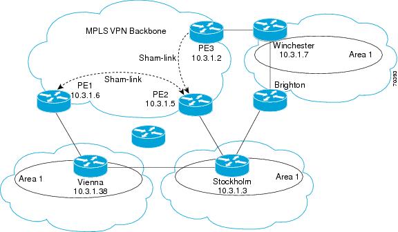
The following example shows how to configure sham links and a demand circuit:

switch(config)# feature-set mpls
switch(config)# feature mpls l3vpn
switch(config)# feature ospf
switch(config)# device ospf class
switch(config-device)# vrf class1
switch(config-device-vrf)# redistribute bgp 100 route-map allow
switch(config-device-vrf)# area 11 sham-link 10.0.0.1 10.0.0.2
switch(config-device-vrf-slink)# demand-circuit
switch(config-device-vrf-slink) # end
 

The following example show how to display the configuration values for demand circuit in sham links for VRF value class1:

switch# sh ip ospf sham-links vrf class1
SL1-0.0.0.0-10.0.0.1-10.0.0.2 line protocol is up
IP address 10.0.0.1, Process ID 100 VRF class1, area 0.0.0.0
State P2P, Network type P2P, cost 1
Run as demand circuit
Index 3, Transmit delay 1 sec
0 Neighbors, flooding to 0, adjacent with 0
Timer intervals: Hello 10, Dead 40, Wait 40, Retransmit 5
No authentication
Number of opaque link LSAs: 0, checksum sum 0
Adjacency Information :
Destination IP address: 10.0.0.2
 

The following example show how to display the configuration values for a demand circuit in sham links for all VRFs:

switch# show ip ospf sham-links vrf all
SL1-0.0.0.0-10.0.0.1-10.0.0.2 line protocol is up
IP address 10.0.0.1, Process ID class VRF class1, area 0.0.0.11
State P2P, Network type P2P, cost 1
Run as demand circuit
Index 1, Transmit delay 1 sec
0 Neighbors, flooding to 0, adjacent with 0
Timer intervals: Hello 10, Dead 40, Wait 40, Retransmit 5
No authentication
Number of opaque link LSAs: 0, checksum sum 0
Adjacency Information :
Destination IP address: 10.0.0.2
SL2-0.0.0.0-10.0.0.1-10.0.0.2 line protocol is up
IP address 10.0.0.1, Process ID class VRF blue, area 0.0.0.11
State P2P, Network type P2P, cost 1
Run as demand circuit
Index 2, Transmit delay 1 sec
0 Neighbors, flooding to 0, adjacent with 0
Timer intervals: Hello 10, Dead 40, Wait 40, Retransmit 5
No authentication
Number of opaque link LSAs: 0, checksum sum 0
Adjacency Information :
Destination IP address: 10.0.0.

Additional References for MPLS Layer 3 VPNs

For additional information related to implementing MPLS Layer 3 VPNs, see the following sections:

Related Documents

Related Topic
Document Title

CLI commands

Cisco Nexus 7000 Series NX-OS MPLS Command Reference

VRF-aware services

Cisco Nexus 7000 Series NX-OS Unicast Routing Configuration Guide

MIBs

MIBs
MIBs Link

MPLS-L3VPN-STD-MIB

To locate and download Cisco MIBs, go to the following URL:

http://www.cisco.com/public/sw-center/netmgmt/cmtk/mibs.shtml

Feature History for MPLS Layer 3 VPNs

Table 22-2 lists the release history for this feature.


Table 22-2 Feature History for MPLS Layer 3 VPNs

Feature Name
Releases
Feature Information

OSPF Sham-Link Support for MPLS VPN

6.2(2)

This feature allows you to use a sham link to connect VPN client sites that run Open Shortest Path First (OSPF) and share back door OSPF links in a Multiprotocol Label Switching (MPLS) VPN configuration.

The following commands were introduced or modified: demand-circuit .

MPLS Layer 3 VPNs

5.2(7)

Added matching and setting support for import maps on standard and extended communities for Cisco NX-OS Release 5.2(7) and later 5.2 releases.

MPLS Layer 3 VPNs

5.2(5)

Removed the MPLS license requirement for the EIGRP site of origin feature.

MPLS Layer 3 VPNs

5.2(1)

This feature was introduced.

6VPE

5.2(1)

This feature was introduced.