Configuring IP Tunnels
This chapter describes how to configure IP tunnels using Generic Route Encapsulation (GRE) on the device.
This chapter includes the following sections:
•![]() Licensing Requirements for IP Tunnels
Licensing Requirements for IP Tunnels
•![]() Displaying Tunnel Interface Statistics
Displaying Tunnel Interface Statistics
•![]() Field Descriptions for Tunnel Interfaces
Field Descriptions for Tunnel Interfaces
Information About IP Tunnels
IP tunnels can encapsulate a same-layer or higher layer protocol and transport the result over IP through a tunnel created between two devices.
This section includes the following topics:
Overview of IP Tunnels
IP tunnels consists of the following three main components:
•![]() Passenger protocol—The protocol that needs to be encapsulated. IPv4 is an example of a passenger protocol.
Passenger protocol—The protocol that needs to be encapsulated. IPv4 is an example of a passenger protocol.
•![]() Carrier protocol—The protocol that is used to encapsulate passenger protocol. Cisco NX-OS supports GRE as a carrier protocol.
Carrier protocol—The protocol that is used to encapsulate passenger protocol. Cisco NX-OS supports GRE as a carrier protocol.
•![]() Transport protocol—The protocol that is used to carry the encapsulated protocol. IPv4 is an example of a transport protocol.
Transport protocol—The protocol that is used to carry the encapsulated protocol. IPv4 is an example of a transport protocol.
An IP tunnel takes a passenger protocol, such as IPv4, and encapsulates that protocol within a carrier protocol, such as GRE. The device then transmits this carrier protocol over a transport protocol, such as IPv4.
You configure a tunnel interface with matching characteristics on each end of the tunnel. For more information, see the "Configuring IP Tunnels" section.
GRE Tunnels
You can use GRE as the carrier protocol for a variety of passenger protocols.
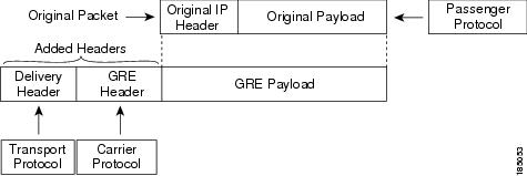
Figure 6-1 shows the IP tunnel components for a GRE tunnel. The original passenger protocol packet becomes the GRE payload and the device adds a GRE header to the packet. The device then adds the transport protocol header to the packet and transmits it.
Figure 6-1 GRE PDU
Path MTU Discovery
Path maximum transmission unit (MTU) discovery (PMTUD) prevents fragmentation in the path between two endpoints by dynamically determining the lowest MTU along the path from the packet's source to its destination. PMTUD reduces the send MTU value for the connection if the interface receives information that the packet would require fragmentation.
When you enable PMTUD, the interface sets the Don't Fragment (DF) bit on all packets that traverse the tunnel. If a packet that enters the tunnel encounters a link with a smaller MTU than the MTU value for the packet, the remote link drops the packet and sends an ICMP message back to the sender of the packet. This message indicates that fragmentation was required (but not permitted) and provides the MTU of the link that dropped the packet.

Note ![]() PMTUD on a tunnel interface requires that the tunnel endpoint can receive ICMP messages generated by devices in the path of the tunnel. Check that ICMP messages can be received before using PMTUD over firewall connections.
PMTUD on a tunnel interface requires that the tunnel endpoint can receive ICMP messages generated by devices in the path of the tunnel. Check that ICMP messages can be received before using PMTUD over firewall connections.
Virtualization Support
You can configure IP tunnels only in the default virtual device context (VDC).
You can configure a tunnel interface as a member of a Virtual Routing and Forwarding (VRF) instance. By default, Cisco NX-OS places you in the default VDC and default VRF unless you specifically configure another VDC and VRF.
See the Cisco DCNM Virtual Device Context Configuration Guide, Release 4.0 for information about VDCs and see the Cisco DCNM Unicast Routing Configuration Guide, Release 4.0 for information about configuring an interface as a member of a VRF.
Note ![]() You must assign a tunnel interface to a VRF before you configure the IP address for that tunnel interface.
You must assign a tunnel interface to a VRF before you configure the IP address for that tunnel interface.
High Availability
IP tunnels support stateful restarts. A stateful restart occurs on a supervisor switchover. After the switchover, Cisco NX-OS applies the runtime configuration after the switchover.
Licensing Requirements for IP Tunnels
The following table shows the licensing requirements for this feature:
Prerequisites for IP Tunnels
IP tunnels have the following prerequisites:
•![]() You must be familiar with TCP/IP fundamentals to configure IP tunnels.
You must be familiar with TCP/IP fundamentals to configure IP tunnels.
•![]() You are logged on to the switch.
You are logged on to the switch.
•![]() You have installed the Enterprise Services license for Cisco NX-OS.
You have installed the Enterprise Services license for Cisco NX-OS.
•![]() You have installed the LAN Enterprise license for DCNM.
You have installed the LAN Enterprise license for DCNM.
•![]() You must enable the tunneling feature in a device before you can configure and enable any IP tunnels.
You must enable the tunneling feature in a device before you can configure and enable any IP tunnels.
Guidelines and Limitations
IP tunnels have the following guidelines and limitations:
•![]() Cisco NX-OS supports the GRE Header defined in IETF RFC 2784. Cisco NX-OS does not support tunnel keys and other options from IETF RFC 1701.
Cisco NX-OS supports the GRE Header defined in IETF RFC 2784. Cisco NX-OS does not support tunnel keys and other options from IETF RFC 1701.
Configuring IP Tunnels
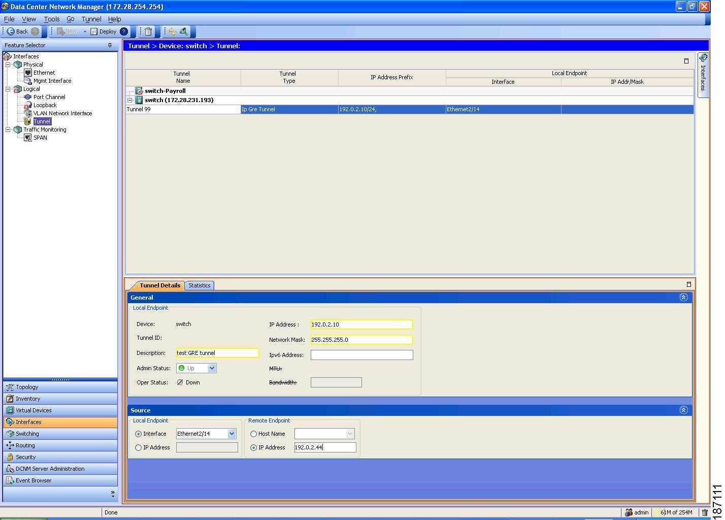
You can access IP tunnels from the Interfaces feature selection. Figure 6-2 shows how to configure IP tunnels.
Figure 6-2 Configuring Tunnel Interfaces
For more information about the Data Center Network Manager (DCNM) features, see the Cisco DCNM Fundamentals Configuration Guide, Release 4.0
This section includes the following topics:
•![]() Displaying Tunnel Interface Statistics
Displaying Tunnel Interface Statistics
Enabling Tunneling
You must enable the tunneling feature before you can configure any IP tunnels.
DETAILED STEPS
To enable the tunneling feature, follow these steps:
Step 1 ![]() From the Feature Selector pane, choose Interfaces > Logical > Tunnel.
From the Feature Selector pane, choose Interfaces > Logical > Tunnel.
The available devices appear in the Summary pane.
Step 2 ![]() From the Summary pane, double-click the device that you want to enable IP tunneling on.
From the Summary pane, double-click the device that you want to enable IP tunneling on.
Step 3 ![]() From the menu bar, choose Tunnel > Enable Tunnel Service.
From the menu bar, choose Tunnel > Enable Tunnel Service.
Step 4 ![]() From the menu bar, choose File > Deploy to apply your changes to the device.
From the menu bar, choose File > Deploy to apply your changes to the device.
Creating a Tunnel Interface
You can create a tunnel interface and then configure this logical interface for your IP tunnel.
BEFORE YOU BEGIN
Ensure that you have enabled the tunneling feature.
DETAILED STEPS
To create a tunnel interface, follow these steps:
Step 1 ![]() From the Feature Selector pane, choose Interfaces > Logical > Tunnel.
From the Feature Selector pane, choose Interfaces > Logical > Tunnel.
The available devices appear in the Summary pane.
Step 2 ![]() From the Summary pane, double-click the device to display a list of existing tunnels.
From the Summary pane, double-click the device to display a list of existing tunnels.
Step 3 ![]() From the menu bar, choose Tunnel > New Tunnel.
From the menu bar, choose Tunnel > New Tunnel.
The system highlights the new tunnel in the Summary pane, and tabs update in the Details pane.
Step 4 ![]() From the highlighted tunnel field, enter the tunnel number.
From the highlighted tunnel field, enter the tunnel number.
The number range is from 0 to 32767.
Step 5 ![]() From the Details pane, click the Tunnel Details tab.
From the Details pane, click the Tunnel Details tab.
The Tunnel Details tab appears.
Step 6 ![]() From the Tunnel Details tab, expand the General section.
From the Tunnel Details tab, expand the General section.
The general tunnel information appears in the Details pane.
Step 7 ![]() (Optional) From the General section, set the IP Address field to the IPv4 address for this tunnel interface.
(Optional) From the General section, set the IP Address field to the IPv4 address for this tunnel interface.
Step 8 ![]() (Optional) In the Network Mask field, set the network mask for this IPv4 address in dotted decimal notation.
(Optional) In the Network Mask field, set the network mask for this IPv4 address in dotted decimal notation.
Step 9 ![]() (Optional) In the IPv6 Address field, set the Primary/prefix length field to the IPv6 address and prefix length for this tunnel interface.
(Optional) In the IPv6 Address field, set the Primary/prefix length field to the IPv6 address and prefix length for this tunnel interface.
The length range is from 1 to 128.
Step 10 ![]() (Optional) From the Description field, enter a string to describe this tunnel.
(Optional) From the Description field, enter a string to describe this tunnel.
The string should be from 1 to 97 alphanumeric characters.
Step 11 ![]() From the Details tab, expand the Source section.
From the Details tab, expand the Source section.
The tunnel source and destination appears in the Details pane.
Step 12 ![]() From the local endpoint area, select either an interface or an IP address to act as the tunnel source.
From the local endpoint area, select either an interface or an IP address to act as the tunnel source.
Step 13 ![]() From the Remote endpoint area, select either an host or an IP address to act as the tunnel destination.
From the Remote endpoint area, select either an host or an IP address to act as the tunnel destination.
Step 14 ![]() From the menu bar, choose File > Deploy to apply your changes to the device.
From the menu bar, choose File > Deploy to apply your changes to the device.
Deleting a Tunnel Interface
You can delete tunnel interfaces.
DETAILED STEPS
To delete a tunnel interface, follow these steps:
Step 1 ![]() From the Feature Selector pane, choose Interfaces > Logical > Tunnel.
From the Feature Selector pane, choose Interfaces > Logical > Tunnel.
The available devices appear in the Summary pane.
Step 2 ![]() From the Summary pane, double-click the device to display a list of existing tunnels.
From the Summary pane, double-click the device to display a list of existing tunnels.
Step 3 ![]() Click on the tunnel that you want to delete.
Click on the tunnel that you want to delete.
Step 4 ![]() From the menu bar, choose Tunnel > Delete Tunnel.
From the menu bar, choose Tunnel > Delete Tunnel.
Step 5 ![]() Click Yes in the confirmation popup window to apply your changes to the device.
Click Yes in the confirmation popup window to apply your changes to the device.
Displaying Tunnel Interface Statistics
You can configure DCNM to collect tunnel interface statistics. Choose Interfaces > Logical > Tunnel from the Feature Selector and navigate to the interface that you want to collect statistics on.
You see the Port Traffic Statistics window. You can collect statistics on input and output (packet and byte) counters, broadcast, multicast, and unicast traffic.
See the Cisco DCNM Fundamentals Configuration Guide, Release 4.0 for more information on collecting statistics for layer 3 interfaces.
Field Descriptions for Tunnel Interfaces
This section includes the following field descriptions for tunnel interfaces:
•![]() Tunnel: Details Tab: Tunnel Details Section
Tunnel: Details Tab: Tunnel Details Section
•![]() Tunnels: Details Tab: Source Section
Tunnels: Details Tab: Source Section
Tunnel: Details Tab: Tunnel Details Section
Tunnels: Details Tab: Source Section
Tunnel: Statistics Tab
Additional References
For additional information related to implementing IP tunnels, see the following sections:
Related Documents
Standards
|
|
|
|---|---|
No new or modified standards are supported by this feature, and support for existing standards has not been modified by this feature. |
— |
 Feedback