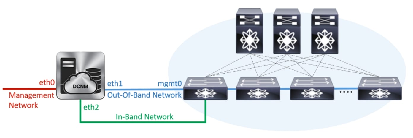
Installing Cisco DCNM on Windows
Perform the following tasks to install Cisco DCNM on Windows.
Uninstalling the Cisco DCNM on Windows
 Note |
We recommend that you follow these steps in the same order. |
Before you begin
Procedure
| Step 1 |
Stop Cisco DCNM Services. |
| Step 2 |
Uninstall the Postgres database. |
| Step 3 |
Uninstall the Cisco DCNM. |
| Step 4 |
Navigate to C:\Users\Administrator location, and delete .cisco_mds9000 folder. |
| Step 5 |
Navigate to C:\Program Files\Zero G Registry location, and delete the Zero G Registry folder. |
| Step 6 |
Navigate to C:\Users\Administrator location, and delete InstallAnywhere folder. |
| Step 7 |
Ensure that all the ports required for Cisco DCNM installation are free and available. |
| Step 8 |
Delete the Cisco DCNM directory. |
| Step 9 |
Restart the Windows VM. |
Downloading the Cisco DCNM Windows Installer and Properties File
The first step to installing the DCNM on Windows is to download the dcnm.exe file.
Note |
If you plan to use Federation application functions, you must deploy the dcnm.exe file twice. |
Procedure
| Step 1 |
Go to the following site: http://software.cisco.com/download/ . |
| Step 2 |
In the Select a Product search box, enter Cisco Data Center Network Manager. Click on Search icon. |
| Step 3 |
Click on Data Center Network Manager from the search results. A list of the latest release software for Cisco DCNM available for download is displayed. |
| Step 4 |
In the Latest Releases list, choose . |
| Step 5 |
Locate the DCNM Windows Installer and click the Download icon. The installer file is of the format . |
| Step 6 |
Locate the DCNM Silent Installer Property Files and click the Download icon. This file will be used during Silent Installation. |
| Step 7 |
Save both the files to your directory that will be easy to find when you begin the installation. |
Installing Cisco DCNM on Windows Using the GUI
Perform the following steps to install DCNM Windows using the GUI:
Procedure
| Step 1 |
Locate the dcnm.exe file that you have downloaded. Double click on the dcnm.exe file. InstallAnywhere progress bar appears showing the progress. |
||||
| Step 2 |
On the Introduction screen, read the instructions. Choose a vendor from the OEM Vendor drop-down list.
Click Next. |
||||
| Step 3 |
Check Add server to existing federation checkbox if DCNM is installed as a secondary appliance in a Federation setup. |
||||
| Step 4 |
Check Secure Ciphers checkbox to allow only switches with strong ciphers to be discovered by DCNM. |
||||
| Step 5 |
To install DCNM-SAN and SMI-S for the first time, choose the location for installation. In the Install Location field, click Choose, and provide the appropriate folder path. Click Restore Default Folder if DCNM is installed as a part of the Federation setup. Click Next. |
||||
| Step 6 |
Choose the appropriate RDBMS for the DCNM server. Select the database that is based on your requirement.
If the Cisco DCNM installer detected an existing RDBMS installation, the DB URL field shows the hostname. Cisco DCNM installation with existing PostgresSQL requires an existing schema with the same name as the DCNM username, which is owned by the same username. When there are no schemas existing with the DCNM username, or if you do not have the ownership of the schema with the same dcnmuser name, the tables are created in the default schema, which is known as “public”.
In the DCNM DB User field, enter the username that the Cisco DCNM uses to access the database. In the DCNM DB Password field, enter the password for the database user account that you specified. If you select Add Server to an existing federation, modify the database URL by selecting the corresponding RDBMS option. Because all the servers in federation refer to the same database, you must provide the dcnmuser name and password of the primary server. Click Next. Review the limitations with Oracle Database and click OK. Click Next. |
||||
| Step 7 |
In the Port Configuration Options screen, choose the interface and web ports for Cisco DCNM.
Click Next. |
||||
| Step 8 |
In the Choose archive Folder for DCNM screen, provide a folder path to store device configuration files, user preferences and so on. Perform one of the following:
Click Next. |
||||
| Step 9 |
In the Local User Credentials screen, provide a valid username and password to access both DCNM SAN and DCNM LAN appliances.
Click Next. |
||||
| Step 10 |
In the Authentication Settings screen, choose the authentication method that the Cisco DCNM server should use to authenticate users who log on to the Cisco DCNM client. You can choose one of the following:
You can configure LDAP authentication after installing DCNM.
|
||||
| Step 11 |
If you chose RADIUS or TACACS+, do the following:
Click Next. |
||||
| Step 12 |
In the Choose Shortcut Folder screen, specify path where you want to create the DCNM icons. If you want the installer to create the shortcuts for all users who can log into the server system, check the Create icons for All Users check box. Click Next. |
||||
| Step 13 |
In the Pre-Installation Summary screen, review the installation configuration. Click Previous to go to the previous tabs and modify the configuration. Click Next. |
||||
| Step 14 |
On the confirmation window, click Yes to begin the DCNM installation. The progress bar description shows the process during the installation. |
||||
| Step 15 |
On the Install Complete screen, the installed components are listed. Click Done to start the DCNM server. Wait until the DCNM is deployed on the system. The prompt will return after the silent install is complete. |
||||
| Step 16 |
Open a browser and enter https://<<DCNM_server_IP_Address>>. Press Return key to launch the Web Interface of Cisco DCNM on Windows for LAN and SAN Management. |
Installing Cisco DCNM Windows in a Server Federation Environment using GUI
To install DCNM in a server federation environment:
Before you begin
Procedure
| Step 1 |
While installing DCNM on the Secondary server, check Add server to existing federation checkbox. This makes the DCNM installed as a secondary appliance in a Federation setup. The Pre-installation Summary screen displays the Federation status and nodes in the Federation Settings area. |
||
| Step 2 |
Check Secure Ciphers checkbox to allow only switches with strong ciphers to be discovered by DCNM, only if the Secure Ciphers was enabled on the Primary. Cisco DCNM uses both strong and weak ciphers when connecting to switches. If user you wants to use only strong ciphers for network, select the checkbox. Ensure that the switches in your network support strong ciphers before you select checkbox, as DCNM will not be able to connect to switches which do not support strong ciphers. |
||
| Step 3 |
Modify the database URL by selecting the corresponding RDBMS option.
The user name and password of the database are same for all the server installation forming the federation. Similarly, the user name and password of DCNM are same for all the server installation forming the federation. |
Installing Cisco DCNM Windows through Silent Installation
Perform the following steps to install DCNM Windows through silent installation.
Procedure
| Step 1 |
Unzip, extract and open the installer.properties file and update the following properties. |
| Step 2 |
Configure the database parameters. If you are using PostgreSQL database, edit this block: If you are using the Oracle database, edit this block: |
| Step 3 |
Configure the user credentials for DCNM. |
| Step 4 |
Enable the Secure Ciphers. |
| Step 5 |
Configure IBM Raven to install IBM Data Center Network Manager. |
| Step 6 |
Navigate to the directory where you downloaded the Cisco DCNM Windows software and run the appropriate installer by using the following command: You can check the status of installation in the Task Manager process. |
| Step 7 |
Open a browser and enter https://<<DCNM_server_IP_Address>>. Press Return key to launch the Web Interface of Cisco DCNM for SAN Management. |

 Feedback