- New and Changed Information
- Preface
- Overview
- Cisco DCNM SMI-S Server Support
- Configuring and Using Cisco DCNM SMI-S Server
- SMI-S Notifications
- Sample SMI-S Java Client
- Managed Object Format Files for Cisco DCNM SMI-S Server
- Introduction to Cisco DCNM for SAN Web Services
- DCNM for SAN Web Services API
- Discovery Automation Tool
- Sample Client Program
- Perl Client
- Command Line Storage Dumps Tool
Cisco DCNM SMI-S Server Support
This chapter describes the standard profiles supported by Cisco DCNM SMI-S. The Cisco DCNM SMI-S Server also supports extensions to these profiles to support features in Cisco MDS NX-OS that are not available from the standard profiles.
Managing SANs Through SMI-S
SANs are created in a multivendor environment. Hosts, fabric elements (switches, directors), and data storage devices are integrated from different vendors to create an interoperable storage network. Managing these elements from different vendors is problematic to the network administrator. Each element has its own management interface that may be proprietary. A network administrator must work with these disparate management APIs to build a cohesive management application that controls and monitors the SAN.
The SMI-S addresses this management problem by creating a suite of flexible, open management API standards based on the vendor- and technology-independent CIM. Using the SMI-S APIs, collected in profiles of common management classes, a network administrator can create a simplified management application CIM client to control and monitor the disparate SAN elements that support SMI-S and CIM. With Cisco DCNM SMI-S Servers either embedded on the SAN elements or supported by a proxy Cisco DCNM SMI-S Server, these elements are accessible to the network administrator’s CIM client application.
SMI-S uses the Service Location Protocol version 2 (SLPv2) to discover Cisco DCNM SMI-S Servers. Once the Cisco DCNM SMI-S Servers are identified, the CIM client determines which profiles are supported on Cisco DCNM SMI-S Servers through the Server profile. This profile is mandatory on all Cisco DCNM SMI-S Servers.
Besides the control and monitoring support provided by profiles, the Cisco DCNM SMI-S Server also supports asynchronous delivery of events through CIM indications. Indications provide immediate notification of important occurrences such as when an interface goes down.
Service Location Protocol
The first step in managing a network of SAN elements with Cisco DCNM SMI-S Server is discovering the location and support available on Cisco DCNM SMI-S Servers. The SLPv2 provides this discovery mechanism. A CIM client uses SLPv2 to discover Cisco DCNM SMI-S Servers, gathering generic information about what services Cisco DCNM SMI-S Servers provides and the URL where these services are located.
Cisco DCNM SMI-S Server supports SLPv2 as defined in RFC 2608.
Server Profile
Once the CIM client discovers the Cisco DCNM SMI-S Servers within the SAN, the CIM client must determine the level of support each Cisco DCNM SMI-S Server provides. The Server profile defines the capabilities of the Cisco DCNM SMI-S Server. This includes providing the namespace and all profiles and subprofiles supported by Cisco DCNM SMI-S Server.
For each supported profile, the Server profile instantiates the RegisteredProfile class. Each instance of this class gives the CIM client the profile name and unique ID that is supported by Cisco DCNM SMI-S Server. Similarly, Cisco DCNM SMI-S Server lists all supported optional subprofiles, using the RegisteredSubProfile class and the SubprofileRequiresProfile association class to associate the subprofile with the profile.
Switch Profile
The Switch profile models the logical and physical aspects of switches. The Computer System class constitutes the center of the switch model. The switch includes discovery components including ports, port statistics, product information, software, and chassis information. It also includes configuration of the switch including switch and port state change, port speed, switch name, symbolic names, and DomainID. Figure 2-1 shows the switch profile from a communication perspective.
The Switch profile also supports the optional Blade subprofile (see the “Blade Subprofile” section) and the optional Access Point Subprofile (see the “Access Point Subprofile” section). Figure 2-2 shows the switch profile from a communication perspective and switch access point subprofile.
Figure 2-1 Switch Profile in Communication Perspective

Figure 2-2 Switch Profile in Configuration Perspective and Switch Access Point Subprofile

Table 2-1 shows how to use the classes and association classes of Switch profile.
Table 2-2 shows the services supported by the switch profile.
Blade Subprofile
This subprofile describes how blades in a director class switch can be discovered and managed.
The CIM client uses the optional Blade subprofile to model the physical and logical aspects of a supervisor module, switching module, or services module in a switch. Combining the Blade subprofile with the Switch profile, the CIM client gains a chassis-level view into the switch, associating ports to modules and modules to a switch. Figure 2-3 shows the switch blade subprofile.
Figure 2-3 Switch Blade Subprofile

Table 2-3 shows how to use the classes and association classes of Blade subprofile.
Access Point Subprofile
The CIM client uses the Access Point subprofile to return the URL to access the switch and install or launch Cisco DCNM-SAN or Device Manager. If Cisco DCNM-SAN or Device Manager have not been installed, then the URL gives the option to install them. If Cisco DCNM-SAN or Device Manager have been installed, then the URL gives the option to launch either of them.
For Access Point subprofile, see Figure 2-2.
Table 2-4 shows how to use the classes and association classes of Access Point subprofile.
Switch Partitioning Subprofile
The Switch Partitioning subprofile is used when a switch is implemented for multiple instances of a profile. The instances of the profile can be a mix of Switch profile and a different profile or a Switch Profile and a Extender Profile. The switch representing the entire set of systems is called the Partitioning System and the system that it is hosting is called the Partitioned System. For virtual fabrics, ANSI T11 calls the partitioning system the Core Switch and the partitioned system the Virtual Switch. Figure 2-4 shows the switch partitioning subprofile.
Figure 2-4 Switch Partitioning Subprofile

Table 2-5 shows how to use the classes and association classes of Switch Partitioning subprofile.
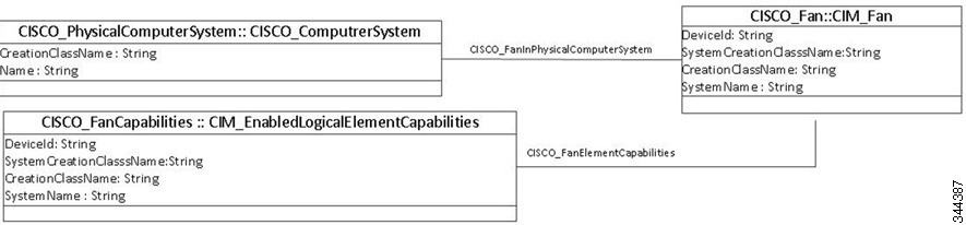
Fan Profile
The fan profile describes the fan management in the switch.This profile includes classes which model for fan capabilities, fan relationship with switches, and its status. Figure 2-5 displays the fan profile.
Power Supply Profile
The power profile describes the power supply management in the switch.This profile includes classes which model for power supply capabilities, power supply relationship with switches, and its status. Figure 2-6 displays the power supply profile.
Figure 2-6 Power Supply Profile
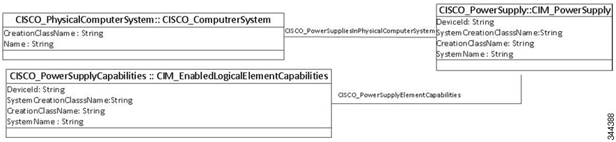
Table 2-6 shows how to use the classes and association classes of the Fan and Power Supply profile.
Fabric Profile
A fabric is composed of one or more switches and network elements interconnected in a SAN. The Fabric profile models the physical and logical aspects of the fabric containing the SAN switches listed by the Switch profile.
The SAN and fabrics are represented in CIM by the AdminDomain. SAN contains one or more fabrics, which are modeled as AdminDomains. For Fibre Channel fabrics, the identifier (AdminDomain.Name) is the fabric WWN which is the switch name of the principal switch. The AdminDomain for the Fibre Channel fabric has a NameFormat of WWN. Fabrics can contain one or more virtual SANs (VSANs). Figure 2-7 shows the fabric profile for zone sets. Figure 2-8 shows the fabric profile for the host computer system. Figure 2-9 shows the fabric profile for storage computer system. Figure 2-10 shows the fabric profile for port.
Figure 2-7 Fabric Profile for Zonest

Figure 2-8 Fabric Profile for Host Computer System

Figure 2-9 Fabric Profile for Storage Computer System
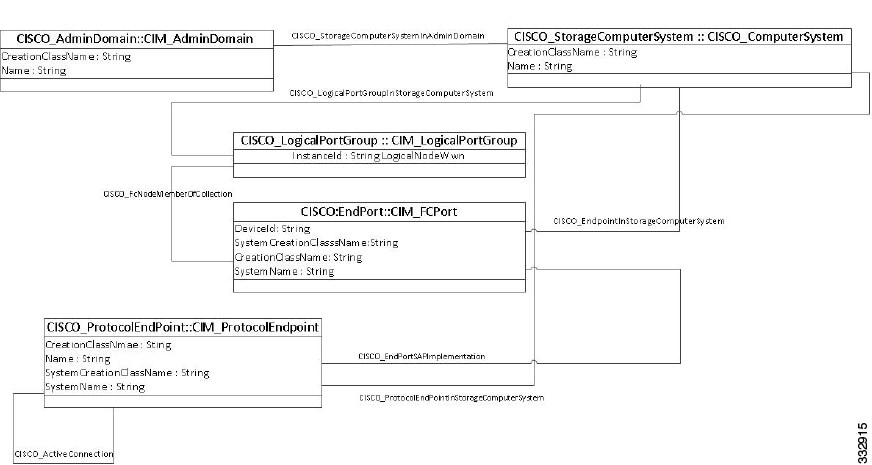
Figure 2-10 Fabric Profile for Port

Table 2-7 shows how to use the classes and association classes of the Fabric profile.
N Port Virtualizer Profile
N port virtualization (NPV) reduces the number of Fibre Channel domain IDs in DCNM-SAN. Switches operating in NPV mode are not part of the fabric and pass traffic between NPV core switch links and end devices and eliminates the domain IDs for these edge switches.
NPV integrates all locally connected N ports into one or more external NP links, which shares the domain ID of the NPV core switch among multiple NPV switches. NPV also allows multiple devices to add to the same port on the NPV core switch, which reduces the need for more ports on the core.
Figure 2-11 N Port Virtualizer Profile
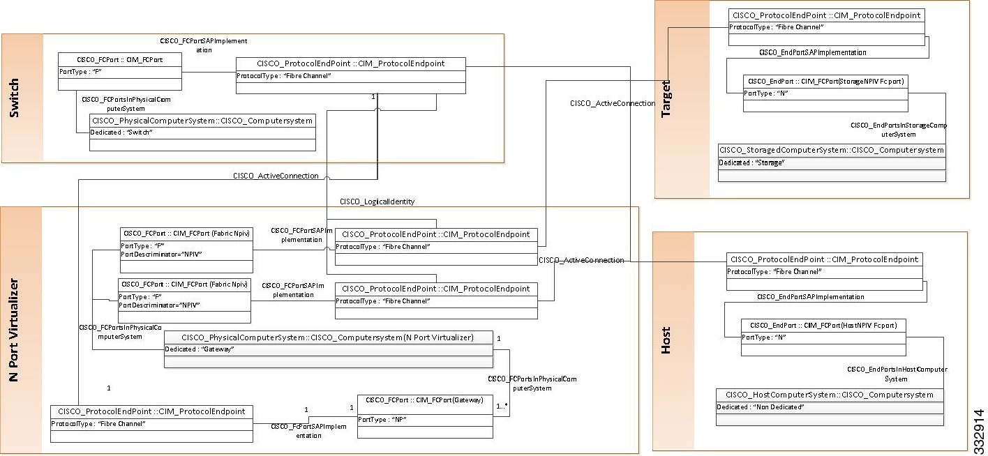
Table 2-8 shows how to use the classes and association classes of the N Port Virtualizer profile.
FDMI Profile
The Fabric Device Management Interface (FDMI) manages host bus adapters (HBA) through the fabric and complements data in the Fabric Profile. It allows any entity in the fabric to expose the HBA information through the SMI without having an agent resident on the host containing the HBA. The Fabric Profile only addresses HBA type devices. The HBA Management Interface defined by FDMI is a subset of the interface defined by the Fibre Channel HBA API specification.
Figure 2-12 shows the FDMI subprofile instance diagram. The classes are defined in CISCO_HBA.mof. If the FDMI- enabled HBA supports the Host name, then CISCO_PortController associates to a platform through CISCO_PortControllerInPlatform. If the FDMI-enabled HBA does not support the host name, then CISCO_PortController associates to a fabric through CISCO_PortControllerInFabric.

Table 2-9 shows how to use the classes and association classes of the FDMI subprofile.
Virtual Fabrics Subprofile
Fibre Channel SANs can logically separate the hardware into multiple fabrics and keep them physically interconnected. The term for this technology is defined by ANSI T11 as virtual fabrics. ANSI T11 identifies the hardware as core switches.
To be consistent with more DMTF schematics, the Virtual Fabrics subprofile names the partitioning systems. ANSI T11 identifies the switching construct that resides in the partitioning system as the virtual switch. The Fabric profile provides the option to discover virtual fabrics and virtual switches. The Virtual Fabrics subprofile provides the option to discover the underlying partitioning system. The Switch Partitioning subprofile provides the method to configure the partitioning system. Figure 2-13 shows the virtual fabrics subprofile.
Figure 2-13 Virtual Fabrics Subprofile
Table 2-10 shows how to use the classes and association classes of theVirtual Fabrics subprofile.
|
|
|
|---|---|
Represents the association between ManagedElements and their capabilities. |
|
Enhanced Zoning and Enhanced Zoning Control Subprofile
This profile describes the additional zoning functions for enhanced zoning. Sessions are normally part of enhanced zoning, but are included in the base fabric profile to address the various types of zoning operations into a single object model. Figure 2-14 shows a enhanced zoning and enhanced zoning control.
Table 2-11 shows how to use the classes and association classes of Enhanced Zoning and Enhanced Zoning Control subprofile.
|
|
|
|---|---|
Extrinsic methods for this subprofile are as follows:
- CreateZoneAlias—Creates a ZoneAlias in the principal switch of the selected VSAN.
- AddZoneAlias—Adds the ZoneAlias to the zone.
Intrinsic methods for this subprofile are as follows:
Figure 2-14 Enhanced Zoning and Enhanced Zoning Control

Zone Control Subprofile
This profile includes extrinsic methods for creating zone sets, zones, and zone members (see Table 2-12) and adding zones to zone sets and zone members to zones. SMI-S also defines intrinsic methods for the removing of zone members from zones and zone aliases, zones from zone sets, and deleting zone members, zones, and zone sets.
Table 2-12 shows how to use the classes and association classes of the Zone Control subprofile.
|
|
|
|---|---|
Associates the ZoneService to the AdminDomain representing the fabric. |
|
Extrinsic methods for this subprofile are as follows:
- CreateZoneSet—The method creates a zone set in the principal switch of the selected VSAN.
- CreateZone—The method creates a zone in the principal switch of the selected VSAN.
- CreateZoneMembershipSettingData—The method creates a zone member and adds it to the specified zone or zone alias depending on the value of the input parameter systemSpecificCollection.
- AddZone—This method adds a zone to a zone set on the principal switch of the selected VSAN.
- AddZoneMembershipSettingData—The method adds the zone member to the specified zone or zone alias depending on the value of the input parameter systemSpecificCollection.
- ActivateZoneSet—This method enables the activation of a zone set.
 Feedback