Contents
Overview
Overview
The Cisco Nexus 9504 switch chassis (N9K-C9504) holds the following components:
-
Supervisor modules (one or two supervisor modules of the same type)
-
System controllers (up to two system controller modules) (N9K-SC-A)
-
I/O modules (up to four I/O modules)
-
48-port 1-/10-Gigabit SFP+ plus 4-port 40-Gigabit QSFP+ I/O module (N9K-X9464PX)
-
48-port 1-/10-GBASE-T plus 4-port 40-Gigabit QSFP+ I/O module (N9K-X9464TX)
-
48-port 1-/10-GBASE-T plus 4-port QSFP+ I/O module (N9K-X9564TX)
-
48-port 1-/10-Gigabit SFP+ plus 4-port QSFP+ I/O module (N9K-X9564PX)
-
36-port 40-Gigabit QSFP+ aggregation (non-blocking) I/O module (N9K-X9636PQ)
-
36-port 40-Gigabit QSFP+ I/O module (N9K-X9536PQ)
-
32-port 40-Gigabit QSFP+ I/O module (N9K-X9432PQ)
-
-
Fabric modules (up to six fabric modules behind the fan trays) (N9K-C9504-FM)
-
Fan trays (three) (N9K-C9504-FAN)
-
AC power supplies (up to four 3-kW AC power supplies) (N9K-PAC-3000W-B)
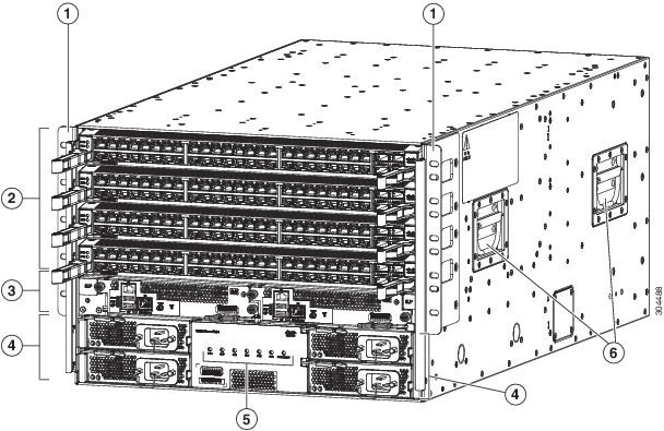
The following figure shows the hardware features seen from the front of the chassis.
|
1 |
Two vertical mounting brackets used to mount the chassis onto a rack |
4 |
3-kW AC power supplies (up to two without power redundancy or up to four with power redundancy) in slots PS 1 to PS 4 |
|
2 |
I/O modules (up to four) in slots LC 1 to LC 4 |
5 |
Chassis LEDs |
|
3 |
Supervisor modules (one or two) in slots SUP 1 and SUP 2 (identified in CLI output as Modules 27 and 28) |
6 |
Chassis handles (used only for positioning the chassis on the bottom support rails—do not use these handles for lifting the chassis) |
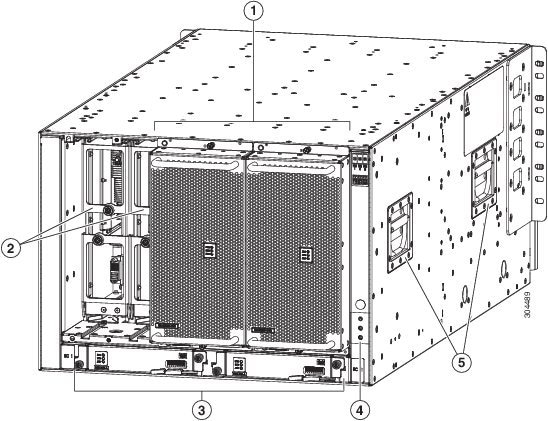
The following figure shows the hardware features seen from the rear of the chassis (one fan tray has been removed to show the fabric modules behind the fan trays).
|
1 |
Fan trays (three—one not shown in order to display the fabric modules located behind the fan trays) in slots slots FAN 1 to FAN 3 (identified in CLI output as Modules 41 to 43) |
4 |
Grounding pad |
|
2 |
Fabric modules (up to six—up to two behind each fan tray) in slots FM 1 to FM 6 (identified in CLI output as Modules 21 to 26) |
5 |
Chassis handles (used only for positioning the chassis on the bottom support rails—do not use these handles for lifting the filled chassis) |
|
3 |
System controllers (two) in slots SC 1 and SC 2 (identified in CLI output as Modules 29 and 30) |