Connecting the Switch to the ACI Fabric
- ACI Fabric Topology
- Preparing to Connect to Other Devices
- Connecting a Leaf Switch to an APIC
- Connecting a Leaf Switch to a Spine Switch
- Setting Up an Optional Console or Optional Out-Of-Band Management Interface
- Maintaining Transceivers and Optical Cables
ACI Fabric Topology
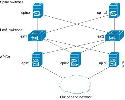
The ACI fabric topology includes the following major components:
-
Application Centric Infrastructure Controllers (APICs) (Cisco UCS C220-M3S servers)
-
Leaf switches (Cisco Nexus 93128TX, 9332PQ, 9372PX, 9372TX, 9396PX, and 9396TX switches)
-
Spine switches (Cisco Nexus 9336PQ, 9504, and 9508 switches)
As shown in the following figure, each of the leaf switches is connected to one or more APICs and connected to all of the spine switches in the same ACI fabric.
Preparing to Connect to Other Devices
When preparing to connect the switch to spine switches and one or more APICs, consider the following for each type of interface, and gather all of the required equipment before making the connections:
-
Cabling type required for each interface type
-
Distance limitations for each signal type
-
Additional interface equipment required
 Note | When running power and data cables in overhead or subfloor cable trays, we strongly recommend that you locate power cables and other potential noise sources as far away as practical from network cabling that terminates on Cisco equipment. In situations where long parallel cable runs cannot be separated by at least 3.3 feet (1 meter), we recommend that you shield any potential noise sources by housing them in a grounded metallic conduit. |
The optical transceivers that are not already assembled to their cables come separate from their cables. To prevent these transceivers and their cables from being damaged, we recommend that you keep the transceivers disconnected from their cables when installing them in ports and then insert the optical cable into the transceiver. When removing transceivers from ports, remove their cables before removing the transceivers.
To maximize the effectiveness and life of your transceivers and optical cables, do the following:
-
Wear an ESD-preventative wrist strap that is connected to an earth ground whenever handling transceivers. The switch is typically grounded when you install transceivers and provides an ESD port to which you can connect your wrist strap. If you cannot find an ESD port, connect the wrist strap to an earth ground (such as the grounding connection for the chassis).
-
Do not remove or insert a transceiver more often than necessary. Repeated removals and insertions can shorten its useful life.
-
Keep the transceivers and fiber-optic cables clean and dust free to maintain high signal accuracy and to prevent damage to the connectors. Attenuation (loss of light) increases with contamination and should be kept below 0.35 dB.
-
Clean these parts before installing them to prevent dust from scratching the fiber-optic cable ends.
-
Clean the connectors regularly; the required frequency of cleaning depends upon the environment. In addition, clean connectors if they are exposed to dust or accidentally touched. Both wet and dry cleaning techniques can be effective; refer to your site's fiber-optic connection cleaning procedures.
-
Do not touch the ends of connectors. Touching the ends can leave fingerprints and cause other contamination.
-
-
Inspect routinely for dust and damage. If you suspect damage, clean and then inspect fiber ends under a microscope to determine if damage has occurred.
Connecting a Leaf Switch to an APIC
You must downlink one or two (recommended for redundancy) Cisco Nexus 93128TX, 9332PQ, 9372PX, 9372TX, 9396PX, or 9396TX leaf switches running in ACI mode) to each Application Policy Infrastructure Controller (APIC) in your ACI fabric (each leaf switch can be connected to multiple APICs). The type of interface cables and leaf switches that you connect to are determined by the type of virtual interface card (VIC) installed on the APIC as follows:
| Step 1 | Connect an
interface cable to one of the two ports on the virtual interface card (VIC)
installed on the APIC. If the cable is not already assembled to its
transceivers, insert the transceiver into the VIC port and then connect the
optical interface cable to the transceiver.
|
| Step 2 | Connect the
other end of the interface cable to a downlink port on a leaf switch.
|
Connecting a Leaf Switch to a Spine Switch
You must connect each Cisco Nexus 93128TX, 9332PQ, 9372PX, 9372TX, 9396PX, or 9396TX leaf switch to every Cisco Nexus 9336PQ, 9504, or 9508 spine switch in the same ACI fabric. The Cisco Nexus 93128TX allows for eight connections (uplink ports 1 through 8) to spine switches, the Cisco Nexus 9396PX and 9396TX switches allow up to 12 connections to spine switches, and the Cisco Nexus 9332PQ, 9372PX and 9372TX switches allow up to six connections to spine switches. To determine which transceivers and cables are supported by this switch, see http://www.cisco.com/c/en/us/support/interfaces-modules/transceiver-modules/products-device-support-tables-list.html. To see the transceiver specifications and installation information, see http://www.cisco.com/c/en/us/support/interfaces-modules/transceiver-modules/products-installation-guides-list.html.
-
The leaf and spine switches must be fully installed in their racks.
-
The leaf and spine switches must be grounded and powered up.
-
If you are using a Cisco Nexus 9504 or 9508 spine switch in the ACI fabric, it must have only the 36-port 40-Gigabit ACI-spine I/O modules (N9K-X9736PQ). You cannot mix other I/O modules in the same chassis when running in ACI mode.
What to Do Next
If the APICs are also connected to the leaf switches, then the ACI fabric is ready to be automatically initiated.
Setting Up an Optional Console or Optional Out-Of-Band Management Interface
You can optionally set up a console or out-of-band management interface for monitoring and troubleshooting purposes. For information on how to set up a console or out-of-band management interface, see the Cisco ACI Getting Started Guide.
Maintaining Transceivers and Optical Cables
Transceivers and fiber-optic cables must be kept clean and dust free to maintain high signal accuracy and prevent damage to the connectors. Attenuation (loss of light) is increased by contamination and should be below 0.35 dB.
Consider the following maintenance guidelines:
Transceivers are static sensitive. To prevent ESD damage, wear an ESD-preventative wrist strap that is connected to the grounded chassis.
Do not remove and insert a transceiver more often than is necessary. Repeated removals and insertions can shorten its useful life.
Keep all optical connections covered when not in use. Clean them before using to prevent dust from scratching the fiber-optic cable ends.
Do not touch the ends of connectors. Touching the ends can leave fingerprints and cause other contamination.
Clean the connectors regularly; the required frequency of cleaning depends upon the environment. In addition, clean connectors if they are exposed to dust or accidentally touched. Both wet and dry cleaning techniques can be effective; refer to your site's fiber-optic connection cleaning procedures.
Inspect routinely for dust and damage. If you suspect damage, clean and then inspect fiber ends under a microscope to determine if damage has occurred.
 Feedback