Overview
The Cisco Nexus 9316D-GX switch (N9K-C9316D-GX) is a 1-RU, fixed-port spine switch designed for spine-leaf-ACI deployment in data centers. This switch has 16 x 400/100-Gbps QSFP-DD ports.
To determine which transceivers, adapters, and cables this switch supports, see the Cisco Transceiver Modules Compatibility Information document.
For breakout information, see the Cisco APIC Layer 3 Networking Configuration Guide.
Leaf/Spine role considerations:
-
This switch's default role is as a spine switch.
-
The default fabric links must be used for initial switch discovery via another switch.
-
To change the switch from the default role, you must proceed as follows: the node appears as a discovered device in the fabric inventory view, you must set the role of the switch (spine or leaf) and the switch automatically goes for reboot to come up in the configured role.
-
If you connect a default spine (i.e. a dual role switch that by default is a spine, such as Nexus 9364-GX) directly to an APIC, the change of the role to leaf is performed automatically by APIC as well as the reboot. After that, the node appears in “Nodes pending registration” and you need to register the node.
Discovery considerations:
-
Discovery via APIC – use the first several ports that will become downlinks after the conversion. All ports are default fabric links and the switch is automatically converted to a leaf switch (reboot is required).
-
Spine discovery – use any port. All ports are default fabric links.
-
Leaf discovery via spine – use the last several ports that will become the fabric links after the conversion. All ports are default fabric links and the switch is automatically converted to a leaf switch (reboot is required).
-
Sub leaf discovery via leaf – use the last several ports that will become the fabric links after the conversion. All ports are default fabric links and the switch is automatically converted to a leaf switch (reboot is required).
This switch includes the following user-replaceable components:
-
Fan modules (six) with the following airflow choices:
-
Port-side exhaust airflow with blue coloring (NXA-FAN-35CFM-PE)
-
Port-side intake airflow with burgundy coloring (NXA-FAN-35CFM-PI)

Note
Table 1. Fan Speeds for This Switch Port-Side Intake
Fan Speed %
Port-Side Exhaust
Fan Speed %
Typical/Minimum
60%
80%
Maximum
100%
100%
Note
Each fan module has two rotors. The switch can function normally if one rotor inside the any one fan module fails. In case of more than one rotor failure, the switch will issue a warning and power down in 2 minute.
-
-
Power supply modules (two—One for operations and one for redundancy [1+1]) with the following choices:
-
1100-W AC power supply with port-side exhaust (blue coloring) (NXA-PAC-1100W-PE3)
-
1100-W AC power supply with port-side intake (burgundy coloring) (NXA-PAC-1100W-PI3)
-
1100-W AC power supply with port-side exhaust airflow (blue coloring) (NXA-PAC-1100W-PE2)
-
1100-W AC power supply with port-side intake airflow (burgundy coloring) (NXA-PAC-1100W-PI2)
-
1100-W HVAC/HVDC power supply with port-side exhaust airflow (blue coloring) (NXA-PHV-1100W-PE)
-
1100-W HVAC/HVDC power supply with port-side intake airflow (burgundy coloring) (NXA-PHV-1100W-PI)
-
1100-W DC power supply with port-side exhaust airflow (blue coloring) (NXA-PDC-1100W-PE)
-
1100-W DC power supply with port-side intake airflow (burgundy coloring) (NXA-PDC-1100W-PI)
Note
Both power supplies use the same type of power source. Do not mix AC and DC power sources.
Note
All fan modules and power supplies must use the same airflow direction during operations.
Note
In the event that only one power supply is operating in an active system and a second power supply is inserted, the system fan will slow down to 50% of Max speed for 12 seconds. It can take up to 10 seconds for the second power supply to become active. Please do not remove the first power supply during this time-frame, in order to avoid system shutdown.
-
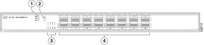
The following figure shows the hardware features seen from the port side of the chassis.
|
1 |
Chassis LEDs (Beacon [BCN], Status [STS], and Environment [ENV]) |
3 |
Lane selector LEDs |
||
|
2 |
Lane selection button
|
4 |
100/400 QSFP-DD ports (16) |
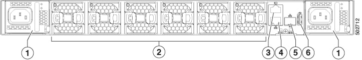
The following figure shows the hardware features seen from the power supply side of the chassis.
|
1 |
Two power supplies (one for operations and one for redundancy) (AC power supplies shown). Power supply slot 1 is on the left and slot 2 is on the right. |
4 |
Out-of-band management port (RJ-45 port) |
|
2 |
Fans (6) |
5 |
Out-of-band management port (SFP port) |
|
3 |
Console port (RS232 port) |
6 |
USB port that is used for saving or copying functions. |
Note |
USB support is limited to USB 2.0 devices that use less than 2.5 W (less than 0.5 A inclusive of surge current). There is no support for devices, such as external hard drives, that instantaneously draw more than 0.5 A. |
Depending on whether you plan to position the ports in a hot or cold aisle, you can order the fan and power supply modules with port-side intake (red colored) or port-side exhaust (blue colored) airflow. All the power supply and fan modules must have the same coloring.
The fan and power supply modules are field replaceable. You can replace one fan module or one power supply module during operations, so long as the other modules are operating. If you have only one power supply that operational, you can install the replacement power supply in the open slot before removing the original power supply.
Note |
All the fan and power supply modules must have the same direction of airflow. Otherwise, the switch can overheat and shut down. |
 Caution |
If the switch has port-side intake airflow (burgundy coloring for fan modules), you must orient the ports in the cold aisle. If the switch has port-side exhaust airflow (blue coloring for fan modules), you must orient the ports in the hot aisle. If you orient the air intake in a hot aisle, the switch can overheat and shut down. |
 Feedback