Contents
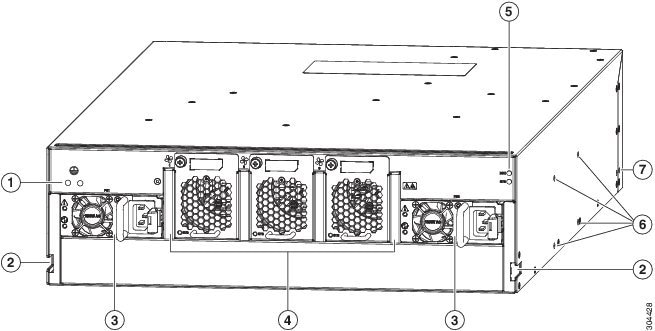
Overview
Overview
The Cisco Nexus 93128TX switch (N9K-C93128TX) is a 3-RU, fixed-port switch designed for spine-leaf-APIC deployment in data centers. This switch has 96 fixed 1/10GBASE-T (copper) ports for APIC connections and 12 fixed 40-Gigabit QSFP+ (optical) ports (of which you can use 8 ports) provided through an uplink module for connections to spine switches. The chassis for this switch includes the following user-replaceable components:
- Uplink modules (one of either of the following for uplink ports)
-
Fan trays (three—two for operations and one for redundancy [2+1]) with the following airflow choices:
-
1200-W AC Power supplies (two—one for operations and one for redundancy [1+1]) with the following airflow choices:
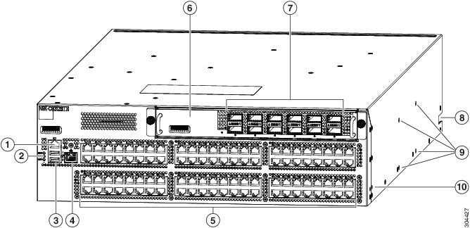
The following figure shows the hardware features seen from the port side of the chassis.
|
1 |
Console port (RS232 port) |
6 |
M6PQ or M12PQ uplink module (M12PQ uplink module shown). |
||
|
2 |
Chassis LEDs |
7 |
6 or 12 40-Gigabit Ethernet Quad Small Form-Factor Plugable (QSFP+) optical ports for uplink connections to spine switches (12-port uplink module shown)
|
||
|
3 |
Two USB ports used for saving or copying functions
|
8 |
Notch in both sides of the chassis for locking the power supply and fan tray end of the chassis to the bottom-support rails |
||
|
4 |
Out-of-band management port (RJ-45 port) |
9 |
Screw holes (4) for attaching a center-mount rack bracket for two-post racks (one bracket for each of two sides) |
||
|
5 |
96 10GBASE-T copper ports (supporting speeds of 100 Megabits, 1 Gigabit, and 10 Gigabits) to Application Policy Infrastructure Controllers (APICs) |
10 |
Screw holes (2) for attaching a front-mount bracket for four-post racks (one bracket on each of two sides) |
The following figure shows the hardware features seen from the fan tray and power supply side of the chassis.