Overview
The Cisco Nexus 9272Q switch (N9K-C9272Q) is a 2-RU with the following ports:.
-
72 fixed 40-Gigabit QSFP+ (optical) interface ports supporting 1-, 10-, and 40-Gigabit speeds
You can breakout up to 35 of these ports to 140 ports supporting 1- and 10-Gigabit speeds.
-
1 console port
-
2 management ports (RJ-45 and SFP)
-
1 USB port
The chassis for this switch includes the following user-replaceable components:
-
Fan modules (two) with the following airflow choices:
-
Port-side intake airflow with burgundy coloring (N9K-C9300-FAN3)
-
Port-side exhaust airflow with blue coloring (N9K-C9300-FAN3-B)

Note
Table 1. Fan Speeds for this Switch Port-Side Intake
Fan Speed %
Port-Side Exhaust
Fan Speed %
Typical/Minimum
50%
70%
Maximum
100%
100%
-
-
Power supply modules (two—one for operations and one for redundancy [1+1]) with the following choices:
-
1200-W port-side intake AC power supply with NEBS compliance with red coloring (NXA-PAC-1200W-PI)
-
1200-W port-side exhaust AC power supply with NEBS compliance with blue coloring (NXA-PAC-1200W-PE)
-
1200-W HVAC/HVDC dual-direction airflow power supply with white coloring (N9K-PUV-1200W)
-
930-W port-side intake DC power supply with green coloring (UCSC-PSU-930WDC)
-
930-W port-side exhaust DC power supply with gray coloring (UCS-PSU-6332-DC)
-
930-W port-side intake DC power supply with burgundy coloring (NXA-PDC-930W-PI)
-
930-W port-side exhaust DC power supply with blue coloring (NXA-PDC-930W-PE)
-
Note |
Both power supplies should be the same type. Do not mix AC, DC, or HVAC/HVDC power supplies. |
Note |
All fan modules and power supplies must use the same airflow direction during operations. If you are using the 1200-W HVAC/HVDC power supplies, those power supplies automatically use the same airflow direction as used by the other modules in the switch. |
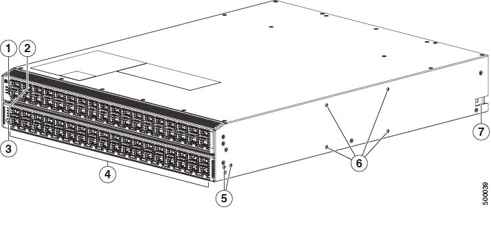
The following figure shows the hardware features seen from the port side of the chassis.
|
1 |
Chassis LEDs
|
5 |
Screw holes (2) for attaching a front-mount bracket for 4-post racks (1 bracket on each of 2 sides) |
|
2 |
Port lane switch button (used for the bottom 36 ports) |
6 |
Screw holes (4) for attaching a center-mount rack bracket for 2-post racks (1 bracket for each of 2 sides) |
|
3 |
Port lane LEDs |
7 |
Notch in both sides of the chassis for locking the power supply end of the chassis to the bottom-support rails |
|
4 |
72 40-Gigabit QSFP+ (optical) ports supporting 1-, 10-, and 40-Gigabit speeds to other devices (ports 37 to 71 support 40-Gigabit-to-4X10-Gigabit breakout cables). |
To determine which transceivers, adapters, and cables are supported by this switch, see the Cisco Transceiver Modules Compatibility Information document.
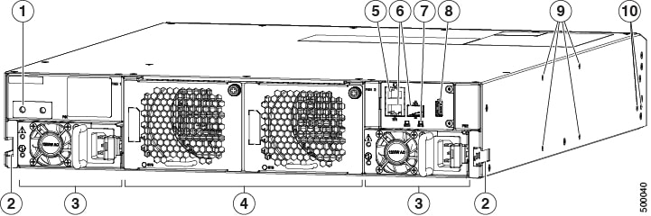
The following figure shows the hardware features seen from the power supply side of the chassis.
|
1 |
Screw holes (2) for attaching the grounding lug to both sides of the chassis. |
6 |
Management ports (2 —RJ-45 and SFP) |
|
2 |
Notch in both sides of the chassis for locking the fan side of the chassis to the bottom-support rails. |
7 |
Chassis LEDs include the following:
|
|
3 |
2 power supplies (one used for operations and one used for redundancy) with power supply slot 1 on the left and slot 2 on the right (AC power supplies shown). |
8 |
USB port (1) |
|
4 |
2 fan modules with fan slot 1 on the left and fan slot 2 on the right. |
9 |
Screw holes (4) for attaching a center-mount rack bracket for 2-post racks (1 bracket for each of 2 sides). |
|
5 |
Console port (1) |
10 |
Screw holes (2) for attaching a front-mount bracket for 4-post racks (1 bracket on each of 2 sides). |
Depending on whether you plan to position the ports in a hot or cold aisle, you can order the fan and power supply modules with port-side intake or port-side exhaust airflow. For port-side intake airflow, the fan and AC power supply modules have burgundy coloring (DC power supply modules have green coloring). For port-side exhaust airflow, the fan and AC power supplies have blue coloring (DC power supply modules have gray coloring). You can also order the 1200-W HVAC/HVDC power supply which has dual-direction airflow with white coloring. Dual-direction airflow modules automatically use the airflow direction of the other modules installed in the switch.
The fan and power supply modules are field replaceable and you can replace one fan module or one power supply module during operations so long as the other modules are installed and operating. If you have only one power supply installed, you can install the replacement power supply in the open slot before removing the original power supply.
Note |
All of the fan and power supply modules must have the same direction of airflow. Otherwise, the switch can overheat and shut down. If you are installing a dual-direction power supply, that module will automatically use the same airflow direction as the other modules in the switch. |
 Caution |
If the switch has port-side intake airflow (burgundy coloring for fan modules), you must locate the ports in the cold aisle. If the switch has port-side exhaust airflow (blue coloring for fan modules), you must locate the ports in the hot aisle. If you locate the air intake in a hot aisle, the switch can overheat and shut down. |
 Feedback