Overview
The Cisco Nexus 93180YC-FX switch (N9K-C93180YC-FX) is a 1-RU, fixed-port switch designed for spine-leaf-APIC deployment in data centers. This switch has 48 10/25-Gigabit SFP+ Application Policy Infrastructure Controllers (APICs) facing ports that support 1-, 10-, and 25-Gigabit Ethernet connections and 8-, 16-, and 32-Gigabit Fibre Channel connections, and it has six fixed 40/100-Gigabit QSFP28 spine-facing ports. The chassis for this switch includes the following user-replaceable components:
 Note |
You can order this switch in a 24-port configuration (N9K-C93180YC-FX-24) |
-
Fan modules (four) with the following airflow choices:
-
Port-side intake airflow with burgundy coloring (NXA-FAN-30CFM-B)
-
Port-side exhaust airflow with blue coloring (NXA-FAN-30CFM-F)
Note
The port-side intake airflow fan module with burgundy coloring can go from 0 to 55 degrees Celsius.
Note
Table 1. Fan Speeds for This Switch Port-Side Intake
Fan Speed %
Port-Side Exhaust
Fan Speed %
Typical/Minimum
50%
70%
Maximum
100%
100%
Note
Each fan module has two rotors. The switch can function normally if one rotor inside the any one fan module fails. In case of more than one rotor failure, the switch will issue a warning and power down in 2 minute.
-
-
Power supply modules (two—one for operations and one for redundancy [1+1]) with the following choices:
-
500-W AC power supply with port-side exhaust airflow (blue coloring) (NXA-PAC-500W-PE)
-
500-W AC power supply with port-side intake airflow (burgundy coloring) (NXA-PAC-500W-PI)
-
1200-W HVAC/HVDC power supply with dual-direction airflow (white coloring) (N9K-PUV-1200W)
-
930-W DC power supply with port-side exhaust airflow (blue coloring) (NXA-PDC-930W-PE)
-
930-W DC power supply with port-side intake airflow (burgundy coloring) (NXA-PDC-930W-PI)
Note
Both power supplies must be the same type of power source. Do not mix AC and DC power sources.
Note
All fan modules and power supplies must use the same airflow direction during operations. If you are using the 1200-W HVAC/HVDC power supply, the power supply automatically uses the same airflow direction as used by the other modules in the switch.
-
Deployment Scheme for SFP-10G-T-X Transceivers
The following figure shows the maximum configuration density of SFP-10G-T-X SFP+ transceivers for this switch.

 |
Active Port deploying the SFP+ 10GBASE-T transceiver, with max power consumption up to 2.5W. Once configured with “media-type 10g-tx” in NX-OS or “Link Level Policy -> Physical Media Type -> SFP 10G TX” in ACI, these ports can deploy SFP-10G-T-X. Without such configuration, they behave like normal ports. |
 |
Port Shutdown or Active with Passive Copper Cables only (Max. power consumption up to 0.1W). Once 10g-tx is configured on yellow ports, ports to the left, right, top and bottom of the yellow port are referenced as blue ports. These adjacent ports will then support only low power Passive Copper DAC cable, or these can be left empty to conserve power. If 10g-tx configuration is removed from adjacent yellow ports, the blue ports will revert to behaving like normal ports. |
 |
Active Port deploying any Cisco 1/10/25G optics (SFP, SFP+, SFP28) EXCLUDING SFP+ 10GBASE-T, with max power consumption up to 1.5W. These ports are not part of any scheme and can deploy all regular Cisco optics and behave like normal ports. |
The following figure shows the hardware features seen from the port side of the chassis.
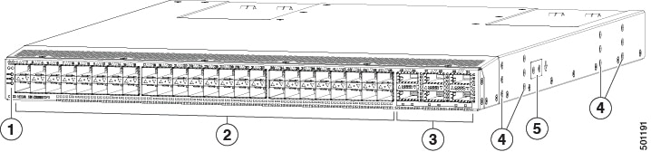
|
1 |
Chassis LEDs (Beacon [BCN], Status [STS], and Environment [ENV]) |
4 |
Screw holes (6) for attaching rack mounting brackets. |
|
2 |
48 10/25-Gigabit SFP28 ports to APICs |
5 |
Screw holes (2) for attaching grounding lug. |
|
3 |
6 40/100-Gigabit QSFP28 optical ports for uplink connections to spine switches |
To determine which transceivers, adapters, and cables this switch supports, see the Cisco Transceiver Modules Compatibility Information document.
The following figure shows the hardware features seen from the power supply side of the chassis.
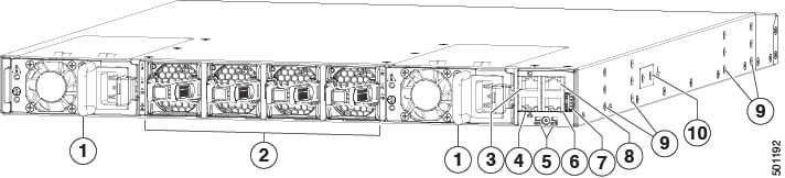
|
1 |
Two power supplies (one used for operations and one used for redundancy) (AC power supplies shown) with power supply slot 1 on the left and slot 2 on the right. |
6 |
Console port (RS232 port) |
|
2 |
Four fan modules with fan slot 1 on the left and fan slot 4 on the right |
7 |
USB port used for saving or copying functions |
|
3 |
L1 (software defined port) |
8 |
Out-of-band management port (RJ-45 port) |
|
4 |
L2 (software defined port) |
9 |
Screw holes (6) for attaching rack mounting brackets |
|
5 |
Chassis LEDs (Beacon [BCN] and Status [STS]) |
10 |
Screw holes (2) for attaching grounding lug. |
Note |
There is a limit to USB 2.0 devices that use less than 2.5 W (less than 0.5 A inclusive of surge current). There is no support for devices, such as external hard drives, that instantaneously draw more than 0.5 A. |
Depending on whether you plan to position the ports in a hot or cold aisle, you can order the fan and power supply modules with port-side intake or port-side exhaust airflow. To determine the airflow direction of the modules installed in your switch, see the following table.
|
Replaceable Modules |
Port-Side Intake Airflow Coloring |
Port-Side Exhaust Airflow Coloring |
|---|---|---|
|
Fans |
Burgundy |
Blue |
|
AC power supplies |
Burgundy |
Blue |
|
HVAC/HVDC power supplies |
White |
|
|
DC power supplies |
Burgundy |
Blue |
The fan and power supply modules are field replaceable and you can replace one fan module or one power supply module during operations so long as the other modules are operating. If you have only one power supply that is installed, you can install the replacement power supply in the open slot before removing the original power supply.
Note |
Fans and power supply modules must have the same direction of airflow. Otherwise, the switch can overheat and shut down. If you are installing a dual-direction power supply, that module will automatically use the same airflow direction as the other modules in the switch. |
 Caution |
If the switch has port-side intake airflow (burgundy coloring for fan modules), you must locate the ports in the cold aisle. If the switch has port-side exhaust airflow (blue coloring for fan modules), you must locate the ports in the hot aisle. If you locate the air intake in a hot aisle, the switch can overheat and shut down. |
The switch supports the Fabric Extenders (FEXs) listed at https://www.cisco.com/c/en/us/td/docs/switches/datacenter/nexus9000/hw/interoperability/fexmatrix/fextables.html.
 Feedback