Overview
The Cisco Nexus 93180LC-EX switch (N9K-C93180LC-EX) is a 1-RU, fixed-port ACI leaf switch with 24 40/50/100-Gigabit Ethernet QSFP+ downlink (server-facing) ports and 6 40/100-Gigabit Ethernet QSFP+/QSFP28 uplink (leaf-switch facing) ports. You can use or configure these ports like this:
-
Downlink ports (ports 1 to 24) are individually configured like this:
Odd-Numbered Port (1 to 23)
Even-Numbered Port (2 to 24) below the Odd-Numbered Port
40-Gigabit QSFP+ downlink port (default)
40-Gigabit QSFP+ downlink port (default)
40-Gigabit downlink port with 4x10-Gigabit breakout feature
Hardware disabled
100-Gigabit QSFP28 downlink port
Hardware disabled
100-Gigabit downlink port with 4x25-Gigabit breakout feature
Hardware disabled
1/10-Gigabit port using a QSFP-to-SFP/SFP+ adapter in the port
1/10-Gigabit port using a QSFP-to-SFP/SFP+ adapter in the port
Note
Even-numbered port must use the same speed as the odd-numbered port in the same vertical pair of ports. Connect the odd-numbered port first to set the speed for the vertical pair of ports.
Profiled as 40/100-Gigabit QSFP+ uplink port
Hardware disabled

Note
-
The breakout feature is available only for release 3.1(1) or later.
-
The top and bottom ports must run at the same speed. If a speed difference occurs, the bottom port disables.
-
The breakout feature is available only for downlink ports 1 to 23, unless those ports are profiled as uplink ports.
-
Autonegotiation is supported on 40G/100G copper DAC cables.
-
-
Uplink ports (25, 27, and 29 to 32) are individually used like this:
-
40/100-Gigabit QSFP+/QSFP28 uplink port (default)
-
-
Hardware disabled ports (ports 26 and 28)
Note |
This switch is not supported in the ACI-mode switch release 6.1(1) and later. |
Note |
The 40/50-Gigabit ports are 50-Gigabit capable, but that speed is not currently supported. |
-
Fan modules (four) with these airflow choices:
-
Port-side intake airflow with burgundy coloring (NXA-FAN-30CFM-B)
-
Port-side exhaust airflow with blue coloring (NXA-FAN-30CFM-F)
Table 1. Fan Speeds for this Switch Port-Side Intake
Fan Speed %
Port-Side Exhaust
Fan Speed %
Typical/Minimum
50%
70%
Maximum
100%
100%
Note
Each fan module has two rotors. The switch can function normally if one rotor inside any one fan module fails. If more than one rotor fails, the switch issues a warning and powers down in 2 minutes.
-
-
Do not mix AC and DC power sources and do not mix airflow directions. Power supply modules (two—one for operations and one for redundancy [1+1]) with these choices:
-
500-W AC power supply with port-side intake airflow (burgundy coloring) (NXA-PAC-500W-PI)
-
500-W AC power supply with port-side exhaust airflow (blue coloring) (NXA-PAC-500W-PE)
-
930-W DC power supply with port-side exhaust airflow (blue coloring) (NXA-PDC-930W-PE)
-
930-W DC power supply with port-side intake airflow (burgundy coloring) (NXA-PDC-930W-PI)
-
1200-W HVAC/HVDC power supply with dual-direction airflow (white coloring) (N9K-PUV-1200W)
Note
If you use the 1200-W HVAC/HVDC power supply, the power supply automatically uses the same airflow direction as used by the fan modules installed in the same switch.
-
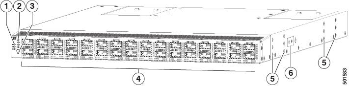
This figure shows the hardware features seen from the port side of the chassis.
|
1 |
Chassis LEDs (Beacon [BCN], Status [STS], and Environment [ENV]) |
4 |
Interface ports (32)
|
|
2 |
Port lane LEDs |
5 |
Screw holes (6) for attaching rack mounting brackets |
|
3 |
Port lane switch button |
6 |
Grounding pad |
To determine which transceivers, adapters, and cables this switch supports, see the Cisco Transceiver Modules Compatibility Information document.
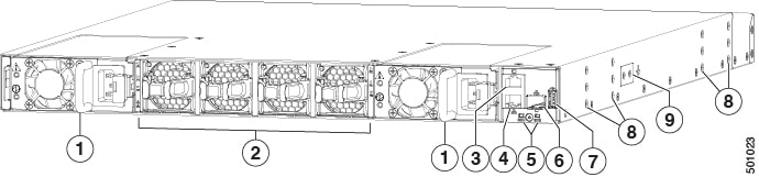
This figure shows the hardware features seen from the power supply side of the chassis.
|
1 |
Two power supplies (one used for operations and one used for redundancy, AC power supplies shown) with power supply slot 1 on the left and slot 2 on the right |
6 |
Management port (SFP+ port) |
|
2 |
Four fan modules with fan slot 1 on the left and fan slot 4 on the right |
7 |
USB port |
|
3 |
Console port (RS-232 port) |
8 |
Screw holes (6) for attaching rack mounting brackets |
|
4 |
Management port (RJ-45 port) |
9 |
Grounding pad |
|
5 |
Chassis LEDs (Beacon [BCN] and Status [STS]) |
Note |
USB support is limited to USB 2.0 devices that use less than 2.5 W (less than 0.5 A inclusive of surge current). Devices, such as external hard drives, that instantaneously draw more than 0.5 A are not supported. |
Depending on whether you plan to position the ports in a hot or cold aisle, order the fan and power supply modules with port-side intake or port-side exhaust airflow. To determine the airflow direction of the modules installed in your switch, see this table.
|
Replaceable Modules |
Port-Side Intake Airflow Coloring |
Port-Side Exhaust Airflow Coloring |
|---|---|---|
|
Fans |
Burgundy |
Blue |
|
AC power supplies |
Burgundy |
Blue |
|
HVAC/HVDC power supplies |
White |
|
|
DC power supplies |
Burgundy |
Blue |
The fan and power supply modules are field replaceable. Replace one fan module or one power supply module during operations, as long as the other modules are installed and operating. If you have only one power supply that is installed, you can install the replacement power supply in the open slot before removing the original power supply.
Note |
All the fan and power supply modules must have the same direction of airflow, or the switch can overheat and shut down. If you are installing a dual-direction power supply, that module automatically uses the same airflow direction as the other modules in the switch. |
 Caution |
If the switch has port-side intake airflow (burgundy coloring for fan modules), locate the ports in the cold aisle. If the switch has port-side exhaust airflow (blue coloring for fan modules), locate the ports in the hot aisle. If you locate the air intake in a hot aisle, the switch can overheat and shut down. |
The switch supports the Fabric Extenders (FEXs) listed at https://www.cisco.com/c/en/us/td/docs/switches/datacenter/nexus9000/hw/interoperability/fexmatrix/fextables.html.
 Feedback